4.0 MEASURED DRAWINGS
76
4.0 MEASURED DRAWINGS 4.1 INTRODUCTION The role of the architect, architecture technician, industrial designer or illustrator on a HAER project is multi-faceted. References to “architects” in the following pages should be treated as referring to anyone delineating HAER drawings. HAER documentation is an interdisciplinary effort which requires teamwork. The architects need the expertise of the historians and photographers just as much as these team members need the architects’ talents; architects cannot work in isolation. Working with historic engineering or industrial sites may present architects with unfamiliar technologies, building structures, materials, and processes. Be sure you get team historians to properly identify site features and help you understand their significance and function. Similarly, if you discover features and dimensions in your field work which do not fit with the historic information you have been given, bring them to the historians’ attention immediately. The data will fill in gaps, challenge certain conclusions, or confirm tentative hunches about the historic record. All team members should develop an open give-and-take among themselves and share data, discuss ideas, interpret data, and determine the best medium for recording various aspects of the site to the Secretary’s Standards. To meet those standards, you must concentrate on documenting what is specifically significant and valuable about your site (including context), prepare your preliminary drawings from accurately recorded field work (or other verified sources), and ink your final drawings on archival HAER Mylar sheets so that the significant features of your site come across “clearly and concisely”. (See the Appendix, Section 5.1 for the text of the Secretary’s Standards.) 4.2 PLANNING DRAWINGS Documentation is necessarily a selective and interpretive process, so you cannot plan a drawing set without having some idea what is significant about your site, and what combination of media will do the best recording job. The entire documentation package must be developed as an integrated whole. Your site’s significance will have been outlined by the HAER office sufficiently to direct your general field work at the very beginning of the project. Consult all materials sent the team by WASO staff, and prepare to spend a few days examining pre-existing documents and exploring the site in earnest. Drawing Sets Below is a checklist of drawings--there are no “standardized” sets of drawings, since every site has its own combination of significant features to record, and its own peculiar collection of surviving records. l Title Sheet. This sheet always contains the name of the structure in bold lettering, a short synopsis of the site’s history, site location maps, a site plan, and project credits. Sometimes a significant elevation, detail, or perspective view is presented. A drawing index is essential for large sets. More details are given in Section 4.7. l Site Plans. These should show existing site conditions. (Historic conditions may also be required.) Site plans should feature plat boundaries, transportation systems, influential geography (rivers, valleys), and significant site structures and services. Topography may need to be included, and if botanical materials (trees, shrubs, plants) are significant, they should be shown and identified by their Latin and common names. 43
-
Upload
vuongthien -
Category
Documents
-
view
228 -
download
0
Transcript of 4.0 MEASURED DRAWINGS

4.0 MEASURED DRAWINGS
4.1 INTRODUCTION
The role of the architect, architecturetechnician, industrial designer or illustrator ona HAER project is multi-faceted. Referencesto “architects” in the following pages shouldbe treated as referring to anyone delineatingHAER drawings. HAER documentation is aninterdisciplinary effort which requiresteamwork. The architects need the expertise ofthe historians and photographers just as muchas these team members need the architects’talents; architects cannot work in isolation.Working with historic engineering orindustrial sites may present architects withunfamiliar technologies, building structures,materials, and processes. Be sure you get teamhistorians to properly identify site features andhelp you understand their significance andfunction. Similarly, if you discover featuresand dimensions in your field work which donot fit with the historic information you havebeen given, bring them to the historians’attention immediately. The data will fill ingaps, challenge certain conclusions, orconfirm tentative hunches about the historicrecord. All team members should develop anopen give-and-take among themselves andshare data, discuss ideas, interpret data, anddetermine the best medium for recordingvarious aspects of the site to the Secretary’sStandards.
To meet those standards, you must concentrateon documenting what is specificallysignificant and valuable about your site(including context), prepare your preliminarydrawings from accurately recorded field work(or other verified sources), and ink your finaldrawings on archival HAER Mylar sheets sothat the significant features of your site comeacross “clearly and concisely”. (See theAppendix, Section 5.1 for the text of theSecretary’s Standards.)
4.2 PLANNING DRAWINGS
Documentation is necessarily a selective andinterpretive process, so you cannot plan adrawing set without having some idea what issignificant about your site, and whatcombination of media will do the bestrecording job. The entire documentationpackage must be developed as an integratedwhole. Your site’s significance will have beenoutlined by the HAER office sufficiently todirect your general field work at the verybeginning of the project. Consult all materialssent the team by WASO staff, and prepare tospend a few days examining pre-existingdocuments and exploring the site in earnest.
Drawing Sets
Below is a checklist of drawings--there are no“standardized” sets of drawings, since everysite has its own combination of significantfeatures to record, and its own peculiarcollection of surviving records.
l Title Sheet. This sheet always contains thename of the structure in bold lettering, a shortsynopsis of the site’s history, site locationmaps, a site plan, and project credits.Sometimes a significant elevation, detail, orperspective view is presented. A drawingindex is essential for large sets. More detailsare given in Section 4.7.
l Site Plans. These should show existing siteconditions. (Historic conditions may also berequired.) Site plans should feature platboundaries, transportation systems, influentialgeography (rivers, valleys), and significantsite structures and services. Topography mayneed to be included, and if botanical materials(trees, shrubs, plants) are significant, theyshould be shown and identified by their Latinand common names.
43

l Historic Site Plans. A series of dated siteplans may be needed to show the developmentof a building, industrial complex or large civilengineering system.
. Site Sections. These are needed to show theway an industrial site or bridge was built toadapt to special topographic conditions.Relationships between buildings or functionsat different levels can be displayed this way.
l Floor Plans. These must show wallmaterials and openings, floor configurationsand finishes, and significant structuralmembers. Machinery, transportation routes,piping, line shafting, and the like should beincluded. Plans may also trace the flow of aprocess or product through a building or site.Cutaway plans may be used in some cases(such as bridges or other modular structures)in order to show typical internal or underlyingstructure.
l Reflected Ceiling Plans. These showsignificant overhead architectural andmechanical details, such as line shafting,ducts, tramways, etc. They may also showstructural systems.
l Elevations. These show the principalfacades of a structure (but not necessarily allsides).
l Sections. Sections show significantinterrelationships among spaces andequipment on different floors or in relation toother features on site. Sections may belongitudinal, transverse, or even one-pointperspectives. Sections are often jogged, thatis, a single section plane is woven through astructure in order to avoid structural membersor objects that would obscure more significantthings in the view.
l Details. Detail views show significantarchitectural and engineering features whoserelationships cannot be clearly displayed atsmall scales. Details can include orthographicviews and sections of machinery, structuraljoints, and special site conditions; they also
44
may include significant architectural details,such as molding profiles, cornices, columns,door and window cases.
l Interpretive Drawings. Interpretivedrawings go beyond orthographic views toclarify, explain and emphasize distinctiverelationships between physical features of thesite and its functions. Such drawings mayrange from reconstructed historicalperspective views of a site (when no historicgraphic views survive); explodedaxonometrics, cutaway views, flow charts ofindustrial processes, or step-by-stepschematics illustrating how a crucial machineor process functions.
Choice of these views, or combinations, willbe governed by the nature of your site and thespecific features which you are recording. Inplanning a series of drawings, you must decidein conjunction with your team where drawingsdo the best documentary job, and wherephotographs and histories would be moreappropriate. Expect many details of a drawingset to change depending on the evolution ofhistorical research and field work at the siteitself.
Unless the WASO office has already developed acomplementary drawing list and sheet layouts inadvance, team architects are expected to developthem within the first week.
Thumbnail Sketches
The team should make thumbnail sketches ofprospective drawings as thinking and talkingpoints (see Fig. 4.1). As you discusssignificant features of the resource, thinkabout several ways to constructively presentthem and use the thumbnail sketches to testtheir effectiveness.
TIP: For very complex structures, building ascale schematic model with cardboard, balsawood, or scrap materials may be a considerablehelp to visualizing how processes operate, andto making decisions about documentation. Itcan also contribute considerably to teamcommunications.

As ideas occur to the team for research,scheduling, and field work, jot them down onthe sketches. Consider what you will baseyour drawings on in order to meet Standard II.Rigorous hand measurements andphotography? Pre-existing drawings, historicphotos, and published materials? Written data?Rectified photography? Photogrammetry?Electronic surveying? Disassembly ofcomponents? In all likelihood, you willdepend on some combination of these sourcesand methods Annotate your thumbnailsketches with the collage of information you
assemble, and begin to sort it out, and pulluseful records. You will need to plan yourwork so that its accuracy and verifiability areappropriate to the significant features you aredocumenting. The whole team will need tocheck each kind of source against the othersand with the site itself in order to ferret outcontradictions and agreements. (Report theseprocedures and their results in your finalproducts.) You should also read the followingsections on field measurement andphotographic techniques to help you select anduse the appropriate media at your site.
Fig. 4.1Preliminary set of thumbnail sketches for a small drawing set
45


Outline for Drawings
Eventually you will arrive at a sequence ofsketches, each covered with notes on what togo after on the site and in the records (seeFigs. 4.2 and 4.3). Refine these images andverbal notes to produce a written outline foreach sheet containing a statement ofobjectives, list of views to be drawn, and apreliminary concept of annotation (Fig. 4.4).
Index to References
List potential secondary sources for eachdrawing and set a written schedule for eacharchitect (Fig. 4.5).
NOTE: Don’t assume the preliminary drawinglist is ironclad--research progress may point toa need for further drawings, or for revisingsome of the previously scheduled ones in orderto meet Standard I.
Half-size Layout Sheets
Within the first two weeks of your project,you should develop a scale mock-up of eachsheet. Fig. 4.6 shows a reduced example. (Thefinal inked sheet is shown in Fig. 4.7 forcomparison.)
Production Phases
Production of measured drawings by handoccurs in four overlapping phases:preparation, field work, preliminary drawings,and finished ink-on-Mylar drawings. HAERprojects usually run for 12 weeks during thesummer. Team size is determined by howmany people are needed to get the job donewithin that time.
Experience indicates you should budget one-third of your time for field work (includingpreparation), one-third for preliminarydrawings, and one-third for inking Mylarsheets. The following sections are organizedby these phases and explain how to meet theSecretary’s Standards.
4.3 FIELD WORK
Field work encompasses any activity whichcollects data about a site. The objective offield work is accurate gathering of significantdimensional and representative data(Standards I and II). It includes shooting fieldphotographs and checking various recordsagainst the site, but it rarely involves anydestructive investigation or archeologicalexcavation. The means for clearly recordingthis data to meet Standards II- IV.
Field work should be conducted according tothe level of accuracy required, schedule,project budget, and the nature of the resourcebeing recorded. HAER sites presentchallenges to recorders, who are often armedwith nothing more than paper, pencils,cameras and hand measuring tools.
Safety
Few sites present openly dangerousconditions, however, even the safest will notprevent injuries stemming from plaincarelessness. It is always your responsibilityto look around, think ahead, and use commonsense. A few reminders are listed below:
. Apparel. Work clothes such as jeans,sweatshirts and sturdy shoes or boots areprotection against dirt and abrasion. Metallicmaterials exposed to sunlight get hot; workgloves should be kept nearby. Hard hatsshould be worn when in operational facilitiesor in deteriorating structures where overheadmaterials have been falling.
l Deteriorated Structures. Don’t go out ontostructures that are obviously deteriorated andunsound. Check the underlying structure inunused or abandoned buildings before goingout onto (or under) floors, beams, roofs, walls.If necessary use ladders, scaffolding andsafety lines. Photography (rectified photos oreven photogrammetry) may be the safest wayto “measure” unsound portions of a structure.
51

Never enter dilapidated buildings alone, andalways use lights in darkened areas. Don’tassume old wiring is “dead”.
l Ladders. Always plant ladders on a firmfooting and tie them down (top and bottom) orhave team members hold them. Ladders arebest for heights under 20 feet. For heightsgreater than 20 feet, scaffolding or cherrypickers are recommended when there is noother means to measure a facade.
l Poison Ivy and Critters. On overgrown orneglected sites, keep an eye out for irritatingplants such as poison ivy and poison oak.Wash any affected skin immediately with soapand water. Be careful in high weeds andunderbrush, since they can conceal thorns orsnakes. Bees and wasps sometimes build hivesin abandoned structures. Mice and rats shouldbe expected, especially around foodstuffs(grain elevators, grist mills).
l Exposure. Use a sunscreen and wear a hat ifyou are outdoors a lot. Drink plenty of waterin the summer to avoid dehydration.
l Animal Droppings. If you encounteraccumulations of bird or animal droppings,avoid stirring up dust from them or contactingthem directly. Illness from them is unusual,but can be serious. If you are going to workfor extended periods of time in fouled areas,wear a mask and protective clothing.
l Asbestos. Asbestos is a white, fibrous,noncombustible and potentially carcinogenicmineral. Historic industrial sites are verylikely to contain pipes, boilers and otherheated equipment insulated with asbestos orconstructed with asbestos-bearing materials(such as floor tiles, shingles, cements, gaskets,etc.). Normally these materials present nodanger to you if the site is well-maintainedand insulation coverings are intact. Looseasbestos is not a serious hazard to workaround briefly if you do not stir it into an
airborne dust cloud. If you should encounterloose asbestos, do not touch it or attempt toremove it.
Locating Existing Records
Before you blanch at the prospect ofmeasuring large or complicated things, see ifyou can find any existing maps, site plans,architectural and engineering drawings,erection plans, textbooks, repair manuals, orother graphics having to do with your site’slayout, buildings and equipment. These maysave you a lot of time and effort. Drawingsusually survive for large utilities(hydroelectric stations, municipal pumping orelectrical stations), major civil engineeringworks (dams, aqueducts, bridges, tunnels,canals) and large industrial sites with alengthy period of operation. They are leastlikely to survive (if they ever existed at all)for small industrial and rural operations, suchas grist mills, blacksmith shops, and the like.Information for and drawings of mass-produced structural members, machinery, andequipment can often be found in periodadvertisements, catalogs, trade journals,technical manuals or patent data. In somecases, documentary information may be theonly way you can conveniently andeconomically get at the historically significantinner structures of buildings or machinerywithout dismantling or destroying the featuresyou are recording. Placement of concretereinforcement and the internal arrangement ofa steam engine are some examples of thissituation. Even if drawings do not show all thelatest changes or cover more than a fewbuildings or machines, they may save youconsiderable measuring time.
52
IMPORTANT CAUTIONS:
1) Older drawings should always be checkedagainst the objects documented by or builtfrom them, since construction errors orchanges may have occurred.
2) Be very careful to check older drawingsand reproductions for scale distortion. Mostreproductions (blueprints, electrostatic prints,etc.) introduce distortions in the direction oftravel of the original document through thecopying apparatus; multiple copy generationsonly magnify the problem. Paper also expandsand contracts across its grain with age,temperature and humidity changes.
3) Most engineering drawings are governedby their written dimensions, not the scale ofthe image; where the two conflict, the writtendimensions rule. So be very careful to checkthe image scale against written dimensionsbefore using old drawings for underlays.Distorted or not-to-scale images may requireyou to rework or redraw reproductions ratherthan trace from them.
TIP: Electrostatic (Xerox@ or equivalent)copies of existing drawings can serve as fieldsketches on which to put check measurementsand any additional field notes (buildingadditions, changes) that you may need torecord. You can use them to make additionalnotes about existing materials and conditions,jotting down any questions or references thatarise.
Explore your site for telltale signs of historicuse, adaptation, repair and demolition. Smellsand sounds can help as much as sight andtouch. Inconsistencies in materials, alignmentof features, or changes in surface finishes andcolors can be valuable clues (see Appendix5.5 for clues identifying metals). Bricked-inwindows and doors, changes or splices inmoldings, partially buried foundations, evenstray bricks and stones of unusual color or size
should be examined as clues to possibleadditions or changes. Wear patterns in floorscan be clues to age, to human and mechanicaltraffic patterns and to the organization of workareas. Some irregularities can be subtle,revealing themselves best in a light held at agrazing angle to a wall or floor. Unexplainedholes, straight or parallel cracks, patches of oilor soot, rust stains, indentations in floors formachinery bases, anchor bolt holes, nail holes,abrasion, rows of empty brackets, “shadows”or holidays in paint finishes--all these shouldbe examined and noted. Look for patterns ofclues, and see if a geometric form appears, orif clues follow an axis, or lead to otherpatterns. Sight down the edges of walls, linesof columns, holes in walls, rows of trusses, tosee if anything unexpectedly regular orirregular shows up. Look at graffiti--some of itmay reveal dates, employee names, workprocedures, employee attitudes, or even workspace organization. Examine the topographyof a site--unusual hollows or hills, even weedsand brush, can be the “X that marks the spot”.Does a room smell particularly of paintsolvents or ammonia, diesel fuel or smoke?You might also listen for sounds as you walkthrough a site or structure--does the floor orground suddenly change from hollow- tosolid-sounding? from masonry- to metallic-sounding? What could be the reasons?
These are only a few of the kinds of cluesabandoned and operating sites contain. Youwill find dozens more.
As you go about your field work, keep yourdrawing list and layout sheets in mind so thatyou gather dimensions relevant to them anddon’t waste time on unnecessary features. It isnecessary to rank the significance of variousfeatures and details, so that a reasonable trade-off between significance, recording methods,schedule, and budget can be made whennecessary.
53

Hand Measuring Tools
Below is a list of basic hand-measuringequipment recommended for field work, someof which is used to establish reference planes.Tapes and rules should be graduated in theEnglish system, not the metric (routinely usedin classical archeology), since most Americanindustrial sites were built using the Englishsystem of feet and inches. (Site plans and platsmay have been laid out in 66-foot surveyor’schains or in decimal feet, depending on theirera--be careful here when comparing modernmeasurements with historic records.)
TIP: However, if you encounter equipmentbuilt to metric dimensions, use metric instru-ments to measure it. Objects should berecorded in the dimensional systems in whichthey were designed in order to best understanddesign ideas and interrelationships.
Storage containers:Toolboxes
Reference Devices:Transit (with tripod)“Torpedo” level (8-inch length)String levelPlumb bobsBraided mason’s or surveyor’s twine
Measuring Devices:300-foot tapes, l/8” graduationsIOO-foot tapes, l/8” graduations50-foot tapes, l/8” graduations6-, 12-, 16-, 25-foot retractabletapes, l/ 16” graduations6-, 8-foot folding carpenter’s rulesl/ 16” graduations
WARNING! Most tapes (especially retract-able ones) are metallic. Fiberglass tapesshould be used around energized electricalequipment to prevent electrocution or fire.
Marking Devices:Lumber crayons (red, black, yellow)Chalk sticks (white, blue, red, yellow)Chalk line reels (with bottles of powderedchalk for refills)Felt markersBallpoint pensPencils
Holding Devices:Masking tapeNails and hammer
Gauges:Contour gauge (“molding comb”)
Hand Tools:HammerPliersScrewdriversUtility (or mat) knife and bladesFlashlights and batteries
Apparel:GlovesFirst aid kitsDust Masks
Data Storage:Clipboards 9"x 12” and 18”x24”)17”x22” field paper, 8 x 8 griddedField notebooksPencils (No. 2 black)ErasersPens (red, blue)
Other:Drawing compass
Other tools that might be utilized by a fieldteam include a carpenter’s square, strongmagnets (for temporarily securing tapes,plumb lines, etc. to steel structures), 2- or 4-foot mason’s levels, protractor level, digitallevel (e.g. “SmartLevel”TM), calculators,spring and jaw calipers, vernier calipers, amagnetic compass, and binoculars.
54

Reference Planes (Datum Lines)
Before measuring any site or structure, it isimperative that independent horizontal andvertical reference planes (often loosely called“datum lines”) be established and marked onthe structures.
WARNING! You should never assume that astructure is level, plumb, or square and then tryto use the structure’s walls and floors as youroverall reference frame.
Reference planes are necessary to help yourwork meet the Secretary’s Standards. Theyare essential to accurately establishing wherethe heights of different features within astructure lie for recording plans, sections andelevations. They are also vital to establishingwhat the inclination of sloped areas is (theyare sloped for a reason). Vertical referenceplanes are less critical, but will be necessaryto establish vertical orientations of walls, andwhether interior features lie over each otherfloor-to-floor or not.
1) Datum planes should be set at heights asconvenient as possible for access throughout abuilding or site.
2) Once a beginning point is selected, try totransfer the level of that point to as manyother places within your site as possible. Thiswill aid you considerably in the drawingphases.
3) Mark the datum plane on structures. Makemarks no more than 15 feet apart, using somerecoverable method. (On some highly finishedstructures you may have to make these marksunobtrusive or put them on removable tape inorder not to damage important finishes.)
WARNING! Failing to leave marks behind willmake it difficult to recover the datum plane tocheck conflicts, errors, and omissions later.
4) When it is time to measure somethingrelative to the datum plane, team members canstretch a string between marks, and use thestring as the datum plane indicator.
Horizontal Reference Planes
There are four major devices for settinghorizontal reference planes:
1) Water Level: This device is extremelysimple, cheap, effective, and nearly foolprooffor setting level reference planes at a site orstructure. It probably antedates the Egyptians,and operates on the elementary principle thatwater seeks its own level (see Fig. 4.8). If itwere practical, you could set a horizontaldatum plane at your site by filling the site withwater, and marking where the water surfaceintersected the structures on a calm day. Thewater surface would be dead level due towater’s response to gravity. A water levelperforms the same function without the flood.If you put water in a tube of any practicallength with open ends, and hold the ends inthe air, will be level with each other regardlessof intervening terrain. (You will need to allowsome time for water to settle from inertia andfriction in the tube). Add some means ofclosing the tube ends so the water won’t spillwhen the level is stored, and perhaps acoloring agent for easier visibility, and youhave a very versatile tool.
Once a beginning point for a datum plane isselected, you can transfer the level of thatpoint as far as the hose will reach.
There are two ways to use a water level (seeFig. 4.9):
(a) The first is to raise/lower the hose endat the initial mark until the water column (A)is aligned with the mark, while another personholds the other end (B) absolutely still. Whenwater column A is aligned, signal the otheroperator to make a mark at the top of thewater column at B. The person at A can speedthe process tremendously by waiting for thewater column to settle (no matter where thatmay be relative to the initial mark), notinghow far above (or below) the water columntop is from the initial mark, then moving thehose twice that distance in the opposite
5.5

I-
Fig. 4.8Using a Water Level
direction. The water column should “split thedifference” and settle very closely to the mark.Repeat this until the mark and water columnare aligned.
(b) Here both hose operators wait until thewater columns settle. Then the person at theinitial mark A measures how far above orbelow the water column is from the initialmark, and tells the second person what thismeasurement is, and where it is relative to thewater column. The second person then makesa mark at the proper measurement. The twomarks should be level with each other sincethey are both the same distance in the samedirection from the level ends of the watercolumn. While this procedure eliminatesadjusting the hose, the second person maymeasure the wrong direction for the secondmark and introduce considerable error,especially when you can’t visually double-check their relative levels because of anintervening obstacle.
For a one-person operation, both procedurestake similar times. Both ends of the hoseshould be taped to the structure, and then thewater column either adjusted or measured atthe initial mark before setting the second.
Fig. 4.9Transferring Datum Plane with Water Level
56

CAUTION: Set as many marks as possiblefrom your initial mark. “Chaining” level marks(using the second mark as the initial mark forthe third, etc.) can result in significant cumula-tivc errors. This problem is analogous to thatwith additive (or cumulative) measurementsdiscussed later.
2. String Levels. A string level consists of abubble level with hooks on each end hung ona strong string. The bubble level should beequidistant between suspension points so thelevel and the string ends are parallel despitethe sag induced by the level’s weight. Set oneend of the string to an initial mark, and raise/lower the other end until the bubble in thelevel is centered. Remove the level from thestring, and mark the string ends and pointsbetween along the string. This procedureworks best with three people, though it can bedone by one person with a way to secure bothends of the string while checking level andmaking marks.
This device depends on its hooks for accuracy.If they are bent or damaged, check the bubblelevel against itself by reversing its position onthe string. If the bubble settles at the samerelative position towards a marked end of thevial, then the string is level, even though thebubble may no longer lie between thecentering marks (see Fig. 4. 1O).
The string level works best over distances lessthan 20 feet. Other reference plane devices aremore consistently accurate and faster to usefor longer distances.
3. Laser Levels. Once properly leveled, thesedevices project a visible red or infrared(invisible) laser beam horizontally, rotating itto describe a datum plane with a beam oflight. You can then mark a structure using thebeam as a guide or measure from features tothe light plane, recording the dimension wherethe beam crosses your scale. The chief
advantages of a laser level are speed of setupand ease of use; one person can makemeasurements to the reference plane with it.(All other instruments are most efficientlyoperated with at least two people.) In brightsunlight, both types, visible red and infraredneed a detector to find the beam, but in shadyor dark places indoors, the visible beam iseasily seen. Laser units are sold as self-leveling or non-self-leveling units. The self-leveling variety typically have an averagelevel accuracy of ‘/2” in 100 feet. The non-self-leveling kind can be adjusted with betterprecision; in addition, many can be set up toproject vertical planes, or stationary lines.New laser units cost about as much as aCategory 1 transit. Many are battery powered,which limits their time at a given set-up; somehave 120v adapters.
If bubble stays in same position(left or right) when level endsare reversed, string is level.
Fig. 4.10Using a string Level
57

CAUTION: Visible light lasers operate at avery low power (about 3 milliwatts, or 3/1000this the power of a flashlight bulb), so theability of a fast-rotating beam to “zap” thingsor damage your eyes is minimal. (The samelasers power bar code scanners in grocerystores and are used by workers to align andhang dropped ceilings). However, danger doeslie in staring for a prolonged time into astationary laser beam. Your eye will focus theenergy onto a very small spot, and time onlymultiplies the energy delivered. So be careful!In the absence of a detector, a visible laserbeam can be seen in bright sunlight by lookingback toward the laser unit from the point atwhich you wish to mark the reference plane.With the laser rotating at I50 RPM at adistance of 50 feet, you will see flashes of two-millionths of a second 150 times a second. Ifyou are still concerned about damage to youreyes, use a small piece of clean window glassfor a reflector/detector. Glass reflects about 5%of the light striking it within 20” of a linenormal to its surface.
4. Transits and Theodolites. Regardless oftheir technology, these instruments measureangles (horizontal and vertical) and distances(range from the instrument station). However,in order to operate properly, they must beleveled (see the Appendix if you are notfamiliar with leveling procedures). Onceleveled, they can be used to set a datum planeon structures through the telescope reticle(cross hairs). Simple mechanical transits(Category 1 instruments) require no powersupply and can set a plane level to within ‘/x”or better for each 100 feet of distance. (Aslong as the instrument is set up, you can alsorecord the heights of features above or belowthe datum plane described with the telescope.)Optical or electronic theodolites can be setlevel more precisely, but they are tooexpensive to use if all you are planning to dois set a level datum plane with them.
TIP: If all you plan to USC a transit for issetting level planes, a builder’s level (com-monly called a “dumpy” level) may be all youneed. These instruments are easier to set up,but they have no vertical circle, and thehorizontal circle cannot measure turns asprecisely as a Category I instrument.
Electronic theodolites with EDM (ElectronicDistance Measurement) capabilities are onlypractical if you need to record dozens orhundreds of control points and plot them inaddition to a datum plane with a CAD systemin a very limited time. Short battery life limitsthese units to between 2 and 6 hourscontinuous operation without access to a 120voutlet, and if you shut them off, you lose allyour settings. Nearly all these instrumentsrequire at least two people to operate themeffectively--a transit operator and someone tomark a point, or hold a measuring tool orprism rod in alignment with the telescope.
Setting Reference Planes with a Transit. Atransit can set planes two ways:
(a) The transit operator can signal a secondperson at the structure to move a marker up ordown until he/she can make a mark in linewith the cross hair in the telescope reticle.This can produce a lot of hand-waving.
(b) The second person at the structure canfirmly hold a tape or folding rule against thestructure where the transit operator can read itthrough the telescope (Fig. 4.11). The operatorthen reads the rule where the horizontal crosshair intersects it and calls out the reading tothe person at the structure who makes a markby that reading on the rule. This is much fasterthan hand-waving.
Once you begin to set reference marks, makesure you set all you will need or can see fromthe instrument station. Unlike the water levelor most laser levels, once you move a transitand tripod, it is impossible to set the
58

instrument up at exactly the same datum planeagain. Try to set a station at a building cornerwhere you can spot at least two elevationsfrom one point, or even see into or throughbuildings to others beyond. Inside structures,try to shoot as far as you can down hallwaysor into adjacent spaces; don’t set up a stationon easily deflected floors--anyone walkingaround the instrument will upset theinstrument’s level plane.
TIP: In some cases you may find it useful toerect a pole or two at a site on which to setdatum marks in order to pick up the plane fromanother instrument station.
On most sites, you will need at least twotransit stations (and perhaps many more) to seta horizontal reference plane. Since youcannot set the instrument up twice in the sameplane, there are two ways to continue a datumplane:
(c) After the instrument is leveled, set yournext series of marks at the second horizontalreference plane, but be sure you measure andrecord the distance between the two planes inyour field notes. This method is faster than thesecond one below, but it can cause confusionin field notes and drawings if the variousdatum planes are not clearly labeled anddistinguished from each other.
(d) After leveling the instrument, measureand record the distance between the newinstrument height and the original referenceplane. Each subsequent sighting indicateswhere the new plane lies, but you measure therecorded distance back to the original planeand mark it on the structure. This takes moretime, but continues the original planeuninterrupted.
Vertical Reference Planes
There are three major devices for settingvertical reference planes:
1. Plumb Bobs. The plumb bob is the simplestand most foolproof vertical reference lineinstrument. Its truth is with two plumb linesby sighting across the visually superimposedstrings and aligning them equidistantly from avertical surface (or other reference points).The line-of-plane can then be used to readswing ties to features (see Fig. 4.12). Theplumb lines could be set up over a grid line orreference line pulled along the ground in orderto take horizontal dimensions with referenceto the plane.
TIP: Wind effects can be greatly reduced byimmersing suspended plumb bobs in contain-ers of water.
Fig. 4.11Using a rule to mark a Datum plane
2. Laser Levels. As mentioned above, somelaser levels can be mounted to project verticalplanes. They can be set or double-checked byhanging plumb lines in the laser plane (thestring will brightly reflect laser light). Toalign the laser plane with a wall, adjust thelaser plane until it crosses two rules set at the
59

I
Fig. 4.12Vertical planes set with plumb lines
ends of the wall at an equal dimension (similarto setting a plane with plumb lines, see Fig.4.12). Use swing ties to measure from featureson the wall to the laser plane.
3. Transits. Transits and theodolites containprecise circles whose aligned by theinstrument frame and the leveling process.Just as the horizontal circle is used to sethorizontal reference planes, the vertical circlecan be used to set vertical reference planes.Move the telescope until equal measurementsare sighted through the reticle on two rules setat the base of a wall (or whatever feature is tobe measured), similar to Figure 4.12. Lock thehorizontal circle and take swing ties fromfeatures to the plane of the vertical circle; readdimensions with the telescope.
Hand Measuring Methods
There are two approaches to systematicmeasurement: additive (or cumulative) andrunning (or consecutive) methods.
l Additive measurements. Additivemeasurements are “chained’‘--each succeedingmeasurement begins where the last one ended(see Fig. 4.13). Grouped and overallmeasurements are obtained by addingindividual measurements. While this methodreduces a lot of measurements to a size that anunassisted person can make with a tape,tolerances/errors accumulate. If you add sixmeasurements, each with a f’/,” tolerance, thesum has a tolerance of 6 x +I/,” or +3/4”.Adding dimensions with different tolerancesgives a total with a final tolerance that is thesum of all the individual tolerances, regardlessof their size. In the end, reasonably carefulmeasuring leaves you with an unreasonableamount of error. (For example, individuallymeasuring the widths of fifty successivefloorboards in a mill to *I/,,” will leave a finaltolerance of f3’/,“!) You may also makeerrors summing fractions, and a recordingerror in one measurement affects the total.
Error is k1/a” for each dimension,5x *1/s” or k’/#” for the sum
Fig. 4.13Additive measurements
l Running measurements. Runningdimensions reduce these problems by usingthe same starting point for all measurementsmade in a common direction (see Fig. 4.14),so they help your work meet Standard II. Forexample, to measure the window openings in abuilding facade, you would hook the tape atone corner, and continue (or "run") down the
60

Error is &I/#” for any dimension
Fig. 4.14Running Measurements
facade, taking the measurement of eachopening edge as it is read from the tape. Eachsuccessive dimension is larger than the onepreceding it, but if you hold a tolerance off’/
” for each dimension, that tolerance is theiame for any individual measurement,independent of all others. Tolerances/errors donot accumulate. Note, however, if you subtractone running dimension from another, thetolerances add, you cannot subtract your wayinto a zero or negative tolerance.
In practice, additive measurement errorsaverage out in many cases, but the totaltolerance cannot be reduced mathematically.Use running dimensions whenever possible.
Be aware of the following in reading tapes, orrecording and plotting dimensions:
Write dimensions in standard U.S. feet-and-inches with a single tic (‘) for feet and adouble tic for inches (“). Insert “0” when afoot or inch dimension is less than one. Oftencommon sense or “fit” to a drawing is notenough to interpret a dimension like 6’- “. Is it“6 feet and one-half inch”, “6 and one-halfinches” or “6 and one-half feet”? Did youforget an inch figure? Avoid ambiguities andensure clarity (Standard IV) by writing this as6’-0 “.
Take care in reading upside down scales; don’tconfuse 6 for 9 or mix up other numerals.
If you read scales opposite to their numericalprogression, don’t associate a fraction with aninteger an inch too high or too low--i.e.,misread 7’/,” as 8’/2”, or 1 07/,” as 1 1 ‘/g”.
Don’t associate a fraction incorrectly with thenearest integer inch--i.e., misread 43/4” as 53/,“.
Take care not to associate a readingincorrectly with the nearest integer foot--don’tmisread 21 “-83/ ” as 22’-8”/ ”
4 4 *
Record dimensions as they appear on the tapeyou are using so you don’t make mathematicalconversion errors. (Some tapes are in inchesonly, some feet and inches-- others featureboth systems.)
TIP: Plotting errors will be less frequent if allyour dimensions are taken in feet and inches,since architectural scales are graduated thatway. Converting inches to feet/inches canresult in plotting errors.
Lastly, be sure you know where the “zero” ison the tape you are using. The “zero” forcarpenter’s tapes is at the tip end with thehook closed. (Some surveyor’s tapes end fourto six inches beyond the tape “zero”; the endis used as a handle.)
l Swing Ties to Lines. The correct distancefrom a point to a line lies along a second linerunning from the point square to the first line(see Fig. 4.15). You do not need to establishthis connecting line with a square in order tomeasure it. All you need to do is put the zeroend of your tape or rule on the point (featurewhose location you are measuring), and swingthe tape by the reference line. The minimummeasurement on the tape is the true
61

dimension. This type of measurement is calleda swing tie. If it were worth your time tocheck it, you would find that the point ofminimum measurement on the reference stringwould lie at the intersection of the squaredconnecting line going to the point on thefeature. (Ordinarily the face of rule shown inFig. 4.15 would be turned 90” so thatswinging the rule will not introduce error from“rocking” the wider end on its corners.)
Fig. 4.15Swing-tie from point to reference line
l Swing Tie Measurements to ReferencePlanes. A similar swing tie is used whenmeasuring heights or depths to a horizontalreference plane over a broad area (deflectedfloors, foundations, remains, etc.). To measurethe depth of a feature beneath a datum planeset by a transit, place the zero end of a rule onthe feature, then sight the scale through thetelescope. The rule should be swung towardsand away from the transit, then left to right. Aminimum measurement should be sought inboth directions, and the procedure repeateduntil a minimum is found (see Fig. 4.16). Aswith the previous example, this minimum isthe true distance between the feature and thereference plane. Sighting the rule through atransit telescope takes more time thanmeasuring to a visible laser level plane. The
laser beam indicates the location of the planedirectly, and you find a minimummeasurement quickly. This kind of swing tiewill work as well with and vertical referenceplanes (see Fig. 4.12), but it does not workeasily at all with a water level or string level.
Fig. 4.16Swing-tie from point to reference plane
. Trilateration. Hand trilateration is simple,powerful, and relatively foolproof for locatingpoints and determining the shape of just aboutanything, so long as measurements arecarefully taken, recorded, and plotted. Notrigonometry is required. Trilaterated pointsare easy to reconstruct at the drawing boardwith a scale and compass.
Use trilateration to measure small site plans,building plans, layouts of columns ormachinery, and the shapes of curves andirregular features. It can also be used tomeasure elevations and bridge arches (see Fig.4.17 through 4.19)
62

l Reference Strings. In complex site or roomplans, trilateration should be supplementedwith a reference string and swing ties,especially where the measured area is slender(see Fig. 4.20). Be sure to measure andannotate the locations of the string ends onyour notes. In cases of conflicts between thereference string and trilaterations, thereference string data is probably more reliable.
Reference strings can also be used as bases fortrilateration. Points can be set along the line atmeasured locations (integer feet areconvenient), and trilaterations made fromthese points to features (see Fig. 4.2 1).
l Poles. For conveniently reaching features upto 20 feet from you with a tape or plumb line,poles are excellent “extenders” for your arms.Poles should be made from one or more 8-footpieces of clear (knotless, crackless) 1 “x2”lumber. (Knots or cracks can lead tofractures.) A series of measurements fromvertical features to horizontal datum lines canbe made very quickly by hooking the zero endof a tape on a pole and holding the end to thefeature you wish to measure. This procedure isfaster than repeatedly moving a heavy ladder.
SAFETY NOTE: Poles made up from a seriesof l”x2”s should have joints that overlap atleast 12” , glued and nailed together.
l Measuring Diameters. The diameters ofsmall piping and round decorative features canbe measured with jaw or spring calipers.Measure the diameters of tanks, penstocks,etc. by taping their circumferences anddividing by n (3.1416). An architecturalcolumn must have circumferences taken atnumerous measured locations along the shaftin order to determine the column entasis.
Fig. 4.17Triangles and trilateration at work
Fig. 4.18Triangles capture room shape
(measure all sides and diagonals)
Fig. 4.19Triangles map arches
(and other various curves)
63

IiiiI
i_,______-_-1
+ymL______- - -
IFig. 4.20
Swing ties to reference string
Fig. 4.21Trilateration from points
on reference string
1
i
ii
ii I
! fi i
-_&_L_bL
I
tL,,llli --I
Fig. 4.22Reference string for
bowed and irregular features
NOTE: This procedure assumes the object istruly circular in section. Tanks, piping, andother “round” shapes in engineering structurestypically have to resist internal or externalpressure--a circular section does this best,aside from being easier to manufacture thannon-circular shapes. You are fairly safeassuming round objects are circular, unlessvisual inspection or drawing board conctssuggests otherwise
Measuring Site Plans
Site plans can be measured using severaldifferent systems: 1. trilateration with tapes 2.bearing and distances with transit and stadiarod 3. rectangular grid system 4. topographicsurveys 5. GPS (Global Positioning Systems).Since most site plans are drawn by HAER atscales of 1”=20’ (1:240) or smaller, theprecision of field measurements is looser thanfor hand-measurement of structures.
1. Trilateration. Before measuring a siteplan, a horizontal reference plane should bestruck on all structures, especially if the sitehas notable topography. Trilaterations shouldbe done in level planes in order to plot themcorrectly in plan.
TIP: Over a distance of 50 feet, a difference inendpoint elevation of 3” or 4” (1 in 200 slope)for a horizontal measurement will have anegligible effect on the measured length. Atape could be leveled with a string level forthis precision.
To begin measuring a site plan, two points“A” and “B” are established as starting points--conveniently the ends of a building wall orthe corners of two buildings. The distancebetween A and B is measured and recorded.The locations of other points (such as thecorners of other buildings or site features) aremeasured from A and B and recorded as pairsof dimensions in tabular form to keep notesneat (see Fig. 4.23). There must be twomeasurements for each new point in order to
64

locate it. At the drawing board, A and B arelocated to scale. To draw each point, adjust acompass to the scale lengths of the legs A andB, and strike arcs. The result will be a plotwith arc crosses, all representing locations ofpoints from A and B.
Fig. 4.23Site plan trilaterations
Eventually you will want to measure two ormore triangles per point in a site plan, both aschecks against errors and as reinforcement forthe accuracy of the job.
TIP: For large sites, begin with large overalltriangles and work smaller ones within them tohold error under control. If you try to constructa site plan from a web of small triangles,cumulative errors will introduce distortions,just as additive measurements accumulateerror.
2. Transit and Stadia Rod. All this entailsis reading precisely the horizontal circle of thetransit, and reading precisely the numbers onstadia rod through the telescope. Every pointrecorded will have a unique pair of numbersconsisting of an angle (bearing) and range(distance) from the transit station.
a
a. Mark the Station Location. When setting upthe transit, be sure to mark the instrumentstation by suspending a plumb bob beneath theinstrument and setting some kind ofreasonably permanent mark on/in the groundor other surface beneath the plumb bob tip.This way, you can recover the station ifcertain measurements prove to be in error.
TIP: Trilaterate the station mark to nearbybuilding or permanent features and record thisdata in case the mark is disturbed.
b. Align the Horizontal Circle. Before you canbegin to record bearings, you need to decidewhere the zero (north) of the horizontal circlewill point. In some cases, aligning it withmagnetic north will be useful, at other times,aligning it with the corner of a building, or anaxial orientation (centered on railroad track orsmokestack) will be more helpful.
c. Reading Stadia Rods and Computing Range.As you look through most transit telescopes,you will notice two small cross hairs on thevertical line of the reticle--one above and onebelow the horizontal line (see Fig. 4.24).These hairs are used to read figures on stadiarods for computation of range. Stadia rodscome graduated in decimal feet (tenths andhundredths of a foot) or feet and inches (12inches to the foot). Before you proceed,examine your stadia rod to see which kind youhave, or your results will be erroneous.
When a stadia rod is held against a buildingcorner or set vertically over a point whosedistance is to be measured, the stadia crosshairs in the telescope will permit you to readan upper and a lower figure on the rod. (Toplumb the rod, try to balance it verticallybetween your fingers, or use a rod level.)Record these two figures, subtract the lowerfrom the upper, and multiply the result by 100.The product is the distance in feet from thetransit to the stadia rod. This calculation ismuch easier with decimal feet than feet andinches.
6.5

Fig. 4.24Range reading with stadia rod
TIP: If for some reason you have to incline thetelescope from horizontal to read the stadiarod, a correction factor must be introduced intoyour calculations, or you will arrive at artifi-cially longer range figures. To obtain thecorrection factor, record the inclination angleon the telescope’s vertical circle, and multiplythe range by the cosine of this angle.
In distance measurement, the accuracy of atransit used with a stadia rod depends on thedistance measured; as long as you can read +0.0 1 foot through the telescope, your toleranceis * I foot.
Total Stations. Total stations are completeelectronic instruments for taking bearing andrange data and converting it to plottablecoordinates with automatic corrections fortelescope inclination. They can also calculateand plot elevations for use in topographicsurveys. The time savings and reduction inerrors from hand calculations can beconsiderable for complex sites. Instrumentmemory can be downloaded to a computer fordata printout (for hand plotting), or creating aCAD plot.
Advanced total stations have accuracies up to+ 1 second of arc (a Category 4 instrument, ortheodolite). Total stations use EDM(Electronic Distance Measurement) devicescapable of accuracies of 2 or 3 parts permillion; at a range of 1,000 feet, you canmeasure range theoretically to within about ‘9,OOO’h\ of an inch (0.036”), greatly exceedingany accuracy requirements in the Secretary’s
Standards. In most cases, a Category 1 transitis sufficient for HAER site work; it requires alittle training to level the instrument properly,set it over a station point, and read the vernierscales correctly. In addition the instrumentrequires no electric power, and is relativelyinexpensive. All data must be read and takendown by hand from a transit, and then youmust reduce the data by hand (with acalculator) to coordinates or range-and-bearing measurements in order to plot points.If run on batteries, total stations may onlyoperate for a short time before batteryrecharging is necessary; check your model tosee if field data will still be saved if thebattery should run down before you finish aday’s work.
3. Rectangular Grid. Many people arefamiliar with photographs of archeologicalexcavations which show strings pulled overthe ground in a rectilinear pattern. This systemaids archaeologists in cataloging and mappinglocations of artifacts. A similar but larger gridsystem may be an advantage in recordingsome site plans where the ground is relativelylevel. The grid could be squared with a transit(or 3-4-5 taped triangle) and marked off withtapes at intervals of 20 or 50 feet. Use the gridintersections as trilateration points for sitefeatures, or take swing ties from features togrid lines.
NOTE: It is wise to make a hard-copy printoutof coordinates in case something damages datastorage media.
66

4. Topographic Surveys. HAER normallyrelies on pre-existing topographic surveys ofsites, or the topography in USGS 7.5 minutetopographic maps for site topography. Atopographic survey would only be requiredwhere these records do not exist or areinadequate to adapt for the display ofsignificant topographic data. If time or budgetdo not allow for a topographic survey, someolder graphic conventions for maps should beemployed to at least indicate the subjectiverelative differences in level observed at thesite (see Field Notes, Section 4.4).
5. GPS or Global Positioning Systems. Theadvent of satellite-based navigational systemshas led to the development of very preciseland surveying instruments that rely onsatellite signals to determine location. Manyof these instruments can resolve landcoordinates in three dimensions to within aninch, but it takes the instrument about 5minutes per station to determine the figures.These systems also operate well only in openareas. Significant tree cover attenuates thesatellite signals too much for accurate work.
Measuring Building Plans
In general, measure plans from the outside in.Angles at corners and between wings can bedetermined by trilateration. Never assumebuildings are square. When an exterior cornerexceeds 180°, one wall can be extended byline of sight to a stake, and the stake positiontrilaterated to the second wall (a similarapproach works on interior corners of thiskind). Plotting these dimensions will establishthe corner angle (see Fig. 4.25). Use ofreference strings and swing ties may be calledfor where there are significant irregularities.After the building perimeter is established,move on to wall thicknesses (obtained fromdoors and windows, or accessible holes), thento interior spaces.
Fig. 4.25Trilaterating exterior comer
Interior plans may require a variety ofapproaches depending on the geometry ofspaces, access to walls and comers, and thepresence of columns, large machinery or otherlarge objects (such as tanks, bins, furnaces,boilers). Don’t forget to set reference planesfirst. In subdivided spaces, every wall shouldbe measured room by room, with at least onediagonal taken in each space. If obstructionsprevent your taking diagonals in one space,you may have to rely on swing offsets andtrilaterations from a reference string or use thegeometries of surrounding rooms to establishthe shape of the less accessible space.Reference strings may be needed to tie a seriesof adjacent irregular spaces togetheraccurately.
NOTE: While measuring for plans, keep inmind measurements that will serve double usein sections.
Features located high above floors may beapproached in several ways; these featuresmay be pipes, ducts, beams, trusses, catwalks,conveyors, decorative features, etc. Look foraccess by catwalks, mezzanines, windows, fireescapes, traveling cranes and the like. Plumb
67

lines can be lowered from these features andtheir locations marked on floors fordimensioning, or for trilateration and swingties to room walls, corners, or referencestrings. The plumb line creates a preciseprojection of overhead features onto the floorbelow.
Measuring Facades
Before you resort to ladders and scaffolding toscale elevations for measurements, considerusing a building’s floors, windows, and fireescapes as de facto scaffolding. Tapes can bedropped from the roof parapets or fromwindows to datum lines for verticalmeasurements; tapes can also be riggedhorizontally from window to window.Binoculars are useful for reading tapessuspended in this manner.
Ladders are best for heights under 20 feet.Above this, scaffolding or cherry pickers arerecommended for safety when there is noother means to lay tapes on a facade.
Poles can be used to hold tapes to featureshigh above datum lines. A series of highvertical measurements can be made muchmore quickly with poles than ladders.
Make sure you set and mark reference planeson the structure(s) first. These will be yourbest (often only) means to sew together acomplex structure accurately. (Remove thesemarks at your project’s end, especially infinished public spaces.)
Always obtain overall measurements first, andwork down to smaller levels of detail. That isthe way you will draw it, so it makes sense tomeasure and record it that way. Repetitivefeatures (columns, windows, details) can bedrawn once and any variable measurementsrecorded in a table. Ask yourself if thevariations are significant enough to spend time
measuring them compared to other priorities.Note down your decisions and tolerances forverifiablity (Standard II).
Some buildings and structures are too large ortoo dangerous to measure by hand. Interiorspaces may be very high and offer little or noaccess to exteriors high above the ground. Ifpre-existing drawings are not available inthese cases, a transit may be the solution. Aplumb bob should be hung beneath theinstrument, and its location in plan carefullytriangulated from the building facade. Itsvertical location relative to the datum planeshould be determined after the instrument isleveled. Facades can then be measured byreading a combination of angles from thehorizontal and vertical circles and reducingthe data trigonometrically to coordinates forplotting at the drawing board or computer.
The above method works best with planarsurfaces. Projections and recessions from thefacade plane will yield errors unless theprojections and recessions are measured.Tilted walls will also yield errors, unless youdetermine compensation factors. In somecases projections can be plumbed for locationrelative to the transit or building facade.However, if space permits you to set yourtransit up at two different points, the methodin Fig 4.26 will address all problems ofprojection, recession and/or tilting. Thismethod requires some basic trigonometry. Thebaseline dimension between the twoinstrument stations is critical to success(whether it is inclined or level). See Section 5for relevant mathematical formulas.
Total stations hold out the prospect ofmeasuring elevations without the tedium ofreducing hand-recorded data. However, theEDM in a total station requires the placementof a prism or reflector at points whosecoordinates are sought. If you cannot gainaccess to place the prism, the total station
68

cannot record the point. As with Category 1transits, anything that interferes with line-of-sight from the instrument will make itimpossible to gather data from the hiddenareas.
Photogrammetry is a photographic techniquefor measuring elevations. While acceptable forHAER documentation, it is not used bysummer teams due to expense of equipmentand need for highly trained operators.Photogrammetry must be supplemented byhand measurement in areas that cannot becovered by cameras.
Fig. 4.26Measuring any height with
two transit stations
Measuring Internal Elevationsand Cross Sections
Measuring plans gives you half thedimensions for cross sections and internalelevations--you have horizontal but notvertical coordinates. Horizontal dimensionstrings taken for constructing a section formultiple floors must be coordinated verticallyby relating each string to a common verticaldatum line (such as might be established by aplumb line). Vertical coordinates can be
established from one or more horizontal datumplanes. The shape of odd or deformedgeometries in section or elevation can bedetermined by trilateration.
Elevations of repetitive features like rooftrusses usually require that you measure oneand assume the others are the same when noobvious differences appear to the eye or arerequired by function. (Take advantage ofsymmetry to reduce measuring time.) Lowerchord joints in trusses can be located byraising a pole with a plumb line to the jointcenterline, or tossing a ball of string over thejoint. A plumb line or measuring tape can thenbe tied to the string and raised to measurevertical heights or establish plan dimensions.A transit, plumb lines and tapes can be used toadvantage also, although for every point yousight you must derive three coordinates for thedata to be useful. These measurements mustbe observed directly or calculatedtrigonometrically. Tapes may also be stretchedover high features and dimensions read fromthe ground with the aid of binoculars.
Floor-over-Floor Position. To accuratelyposition floors over ones beneath, try lookingfor holes in floors through which to dropplumb lines, or hang them in stairwells or pipechases. Measure the locations of thesuspension point on the upper floor and of theplumb bob tip on the floor beneath and plotthese points in the plans of the two floorsbeing checked. Two such plumb lines areneeded to “lock” the two floors together. Thisrelationship will also help in plotting andchecking sections.
Measuring Trussed Structures
Metal and wooden truss structures aredistinctive features of American engineeringhistory, and they are frequently recorded forHAER. The following procedures will applyequally well to truss bridges, roof trusses,towers, and other trussed structures.
69

Try to locate engineering drawings beforeresorting to complete measurement, especiallyif the trusses are large, or consist of multiplespans. Drawings will often be your only clueto rivet sizes and internal joint construction.(Rivet are sized by their shank diameter, nothead diameter.) A chart of common truss typesand bridge part terminology is provided inFigure 5.15.
Truss Components. If field measurement isrequired, the measurements needed to record atruss break down into several easily definedgroups, regardless of the truss type (see Fig.4.27). On bridges, the span between the centerline of the truss bearing points must bemeasured first (a), followed by the distancebetween the center line of the truss planes (b),then the distance between the center line ofthe top and bottom chords (c) (if the truss hasparallel chords). If a bridge is skewed in plan,the relative position of the trusses can beobtained by trilateration in plan. You shouldalso sight along upper and lower chords tocheck for vertical camber; if any exists youmay need a transit or water level to measure it.
Symmetry. Considerable time can be savedmeasuring a metal bridge by taking advantageof its numerous symmetries. First, the twotrusses of a simple bridge span are usually thesame, even if the bridge is skewed in plan.Second, an individual truss is usuallysymmetrical about its centerline between ends.Third, these same observations apply to decksand upper chord bracing. In effect, you mightmeasure only l/4 of the bridge after overalldimensions are obtained.
WARNING: These observations may not
apply to “vernacular” bridges.
Panels. After obtaining overall dimensions,the dimensions of truss panel points must betaken and recorded (see Fig. 4.28). In mostbridges, the panel points are evenly spacedalong the top and bottom chords, but this isnot always the case.
L
Fig. 4.27Basic truss measurements
Fig. 4.28Panels of pin-connected truss
Measuring between panel points of a metaltruss bridge is easy if the bridge is old enoughto be pin-connected--dimensions are simplytaken between the centerline of each pin alongthe chords and for all diagonals and verticals.(The pin centerline is frequently marked in theends by dimples or countersunk holes used toturn the pin in a lathe.) If your bridge iswooden or has riveted joints, you are better
70
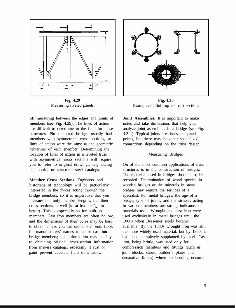
Fig. 4.29Measuring riveted panels
off measuring between the edges and joints ofmembers (see Fig. 4.29). The lines of actionare difficult to determine in the field for thesestructures. Pin-connected bridges usually hadmembers with symmetrical cross sections, solines of action were the same as the geometriccenterline of each member. Determining thelocation of lines of action in a riveted trusswith asymmetrical cross sections will requireyou to refer to original drawings, engineeringhandbooks, or structural steel catalogs.
Member Cross Sections. Engineers andhistorians of technology will be particularlyinterested in the forces acting through thebridge members, so it is imperative that youmeasure not only member lengths, but theircross sections as well (to at least f’/,,” orbetter). This is especially so for built-upmembers. Cast iron members are often hollow,and the dimensions of their cores may be hardto obtain unless you can see into an end. Lookfor manufacturers’ names rolled or cast intobridge members; this information may be keyto obtaining original cross-section informationfrom makers catalogs, especially if rust orpaint prevent accurate field dimensions.
Fig. 4.30Examples of Built-up and cast sections
Joint Assemblies. It is important to makenotes and take dimensions that help youanalyze joint assemblies in a bridge (see Fig.4.3 1). Typical joints are shoes and panelpoints, but there may be other specializedconnections depending on the truss design.
Measuring Bridges
On of the most common applications of trussstructures is in the construction of bridges.The materials used in bridges should also berecorded. Determination of wood species inwooden bridges or the minerals in stonebridges may require the services of aspecialist. For metal bridges, the age of abridge, type of joints, and the stresses actingin various members are strong indicators ofmaterials used. Wrought and cast iron wereused exclusively in metal bridges until the1860s when Bessemer steels becameavailable. By the 1880s wrought iron was stillthe more widely used material, but by 1900, ithad been completely supplanted by steel. Castiron, being brittle, was used only forcompression members and fittings (such asjoint blocks, shoes, builder’s plates anddecorative finials) where no bending occurred.
71

Fig. 4.31Example of joint assemblies
Built-up wrought iron and steel shapes oftenserved for compression members as trussbridge engineering matured; they were alwaysused for tension members and memberssubject to bending loads (such as floor beamsand stringers). HAER has recorded a handfulof bridges with cast iron floor beams, butthese are very rare survivors.
Anomalies. Deformations, deterioration,asymmetries, (and even missing members)should be recorded since they may beimportant clues to the success or weakness ofthe bridge’s original design, detailing, andconstruction.
Decorative Features. Builders’ plates,dedication plates, and decorative featuresshould be recorded.
Masonry Bridges. The exterior shapes ofmasonry bridges can be recorded by methodsused for buildings. Internal construction isvery difficult to infer without originaldrawings, photographs, or some convenientdamage that allows you to look into a crosssection of arches or piers. Arch shape can berecorded by trilateration from spring points orbridge piers. Very large spans can be recordedwith a transit.
Concrete Bridges. Discovery of originalconstruction drawings is vital to properlydocument reinforcing bar type, sizes, andplacement. Without this information, all youcan measure are the architectural appearanceand outer dimensions of these structures.
Suspension Bridges. This distinctive bridgetype will involve you in the documentation oftrusses (roadway stiffening trusses, perhapstowers), as well as cables, anchorages,saddles, and specialized joints. An importantthing to remember in recording and drawingthe main cables is that their shape follows acatenary curve, not an elliptical or circular arc.
TIP: A catenary curve can be duplicated in adrawing by putting the drawing on a wall,suspending a fine beaded chain between thetower tops and the plotted bottom of the cablespan, and marking the centerline of the chainevery inch or two. These marks can then beconnected by flexible curves. The beadedchain hangs in a catenary curve.
Cable construction should be carefullydetermined. The use of engineering handbooksand manufacturers’ catalogs is encouraged.
Measuring Machinery
Machinery is a much broader category ofresource to measure than bridges.
Nonetheless, there are some basic rules formeasuring mechanical devices. You will needto use your ingenuity in special cases.
72
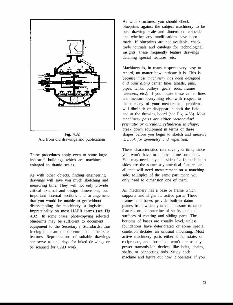
Fig. 4.32Aid from old drawings and publications
These procedures apply even to some largeindustrial buildings which are machinesenlarged to titanic scales.
As with other objects, finding engineeringdrawings will save you much sketching andmeasuring time. They will not only providecritical external and design dimensions, butimportant internal sections and arrangementsthat you would be unable to get withoutdisassembling the machinery, a logisticalimpracticality on most HAER teams (see Fig.4.32). In some cases, photocopying selectedblueprints may be sufficient to documentequipment to the Secretary’s Standards, thusfreeing the team to concentrate on other sitefeatures. Reproductions of suitable drawingscan serve as underlays for inked drawings orbe scanned for CAD work.
As with structures, you should checkblueprints against the subject machinery to besure drawing scale and dimensions coincideand whether any modifications have beenmade. If blueprints are not available, checktrade journals and catalogs for technologicalinsights; these frequently feature drawingsdetailing special features, etc.
Machinery is, in many respects very easy torecord, no matter how intricate it is. This isbecause most machinery has been designedand built along center lines (shafts, pins,pipes, tanks, pulleys, gears, rods, frames,fasteners, etc.). If you locate these center linesand measure everything else with respect tothem, many of your measurement problemswill diminish or disappear in both the fieldand at the drawing board (see Fig. 4.33). Mostmachinery parts are either rectangularlprismatic or circular1 cylindrical in shape;break down equipment in terms of theseshapes before you begin to sketch and measureit. Look for symmetry and repetition.
These characteristics can save you time, sinceyou won’t have to duplicate measurements.You may need only one side of a frame if bothsides are the same; asymmetrical features areall that will need measurement on a matchingside. Multiples of the same part mean youonly need to dimension one of them.
All machinery has a base or frame whichsupports and aligns its active parts. Theseframes and bases provide built-in datumplanes from which you can measure to otherfeatures or to centerline of shafts, and thesurfaces of rotating and sliding parts. Thebottoms of bases are usually level, unlessfoundations have deteriorated or some specialcondition dictates an unusual mounting. Mostactive machinery parts either slide, rotate, orreciprocate, and those that won’t are usuallypower transmission devices like belts, chains,shafts, or connecting rods. Study eachmachine and figure out how it operates, if you
73

cannot observe it in motion. An understandingof its operation will help you simplify yournotes and avoid taking misleading orunnecessary measurements. It is moreimportant to measure the configuration ofparts whose relationship does not change as amachine operates rather than dimensionchanging relationships. For example, on areciprocating steam engine, it is moreimportant to have the length of the connectingrod from the wrist pin to the crank pin and thethrow of the crankpin, than it is to measure thedistance of the wrist pin from the cylinderhead. The connecting rod and crankpindimensions never change; the position of thewrist pin is always changing as the engineruns, although the possible positions arelimited by the geometry of the rod length andcrank throw.
Always record center lines before details.Locate major center lines of bases, shafts,cylinders, motors, gears, etc. from each otherand from primary reference surfaces such asbases or datum planes. Your first sketches anddimensions should address only these centerlines in elevation, plan, and section (see Fig.4.33). Look for physical features which definethe centers of shafts, cylinders, and bases(such as center holes in shaft ends, bolts atframe center lines, joints in casings, bearings,castings). Where no physical indications areapparent, you will have to mark center linesby halving the widths of round and rectangularelements. Datum surfaces like bases can beartificially extended by placing a straight 2” x4” or long mason’s level under the edge andleveling the level to it (check that the machinebase is level first). Having done this, you canthen measure up from the level to variouscenter lines, swinging the level as needed toget in position. Plumb lines will “drop” centerlines to a datum plane for horizontal positionmeasurements (you can also use the verticalvials in a mason’s level). Magnets can be usedto hold tapes in place on iron or steelmachinery. Once the defining center lines are
documented, you can proceed to measureprincipal parts like pulley and gear diameters,and bearing sizes. Leave small (but important)details such as nuts and bolts, pulley spokes,and piping for last. See sections on field notesand field photography for further instructions.
Fig. 4.33Machinery designed around center lines
Pay particular attention to the angular or radialalignment of keys, spokes, part lines, moldinglines, pins, bolts and other features of differentparts around a common shaft (see Fig. 4.34).These can be measured using a level andprotractor, or a combined protractor-level.
TIP: Many parts such as fasteners, pipes,valves, structural steel sections, rails, chains,and cables come in standardized sizes dimen-sioned in engineer’s handbooks or otherreferences. These will save you time indimensioning and labeling. Avoid measuringworn areas for principal cross sectionaldimensions.
74

Almost all machinery comes with basicinformation cast into frames or embossed onmanufacturer’s plates mounted in a prominentplace. All the information on these platesshould be copied into your field notes. Thisdata records the manufacturer’s name,address, dates, serial numbers, modelnumbers, and often patent numbers. Furtherinformation pertinent to the machine may alsobe given, such as cylinder sizes, horsepower,voltage and amperage, pumping capacities,pressures, temperatures, lubrication andoperation instructions, and safety procedures.Beyond this, recording of numbers and verbalinformation depends on its significance to themachine and the site. Numbers and letters castinto frames or embossed into parts may be partof a system of part numbers, mold numbers, oreven serial numbers. Some may be matchnumbers used to show which parts should bejoined after they have been disassembled forrepair.
Interureting Industrial Processes
Frequently the significance of a site lies asmuch in the industrial process going on insidethe buildings as it does in the buildingsthemselves or their machinery. You shouldcarefully note the steps in manufacture of aproduct, or the way equipment is oriented andoperated. You may need to trace pipes, belts,conveyors, tracks, shafts, canals, tunnels andwires in order to understand where, how andwhy materials and energy moved throughoutthe site. Specialized machinery and materialsshould be noted. Chemical reactions,quantities, temperatures, sequences, andbyproducts should be determined where theyare significant to a site’s function. Electrical,mechanical, and hydraulic data should berecorded for systems where voltages,amperages, horsepower, pressures, andvolumes are significant to operations.
Fig. 4.34Radial location of parts
Points of wear on floors, equipment, orstructures can offer meaningful clues to workpatterns and flows of material and products.The age of equipment, manufacturing methodsused, and working conditions will be of greatinterest to historians. The team historians’research and insights will be critical when thebusiness has closed down, or the site has beenpartially dismantled. You will have to call onyour imagination to piece operations togetherfrom holes in walls, “ghosts” on floors wheremachines once stood, structural alterations,and other silent features.
7.5

4.4 FIELD NOTES
Field Note Material
HAER uses 17”x22” gridded bond paper(sometimes called “layout paper” or “cross-section paper”). This size folds convenientlyto 8 " x 11" for storage in field notebooks andlater filing at the Library of Congress(Standard III). These sheets may be gluedtogether with a white glue (1ike”Elmer’s Glue-all” or similar polyvinyl acetate (PVA) glues)for larger sheets, just so the notes foldconveniently to 8 ". x 1 1” format. Tape isunacceptable because its adhesives failquickly. Scraps of paper snatched fromnotepads, “post-ems”, backs of envelopes andthe like are unacceptable because they areeasily lost. Torn or abraded field notes shouldbe repaired with glued on strips of field notepaper for permanence.
There is an important exception to Standard III asapplied to field notes: they need not be onarchivally stable paper, because field notes areinevitably contaminated with dirt, perspiration, oilsand other substances at industrial sites. If archivalstability is an absolute must, notes should becopied over by hand onto clean archivally stablegridded paper, or reproduced electrostatically.Original notes must always be submitted to theLibrary of Congress.
Sketches should be made in No. 2 pencil.Changes are easy to make, and graphite doesnot fade with time nor run if accidentallyexposed to water (rain, etc.). Dimensions,dimension strings, and witness lines shouldalways be recorded in red in order to clearlydistinguish them from black pencil lines thatdenote structure (Standard IV). Use a redpencil or a pen with a good non-dye basedball-point ink. (Imagine how even Fig. 4.38would be improved with dimensional data inred!) Large mistakes should be crossed outrather than erased. Paper is cheap compared toyour time. If erasures thin a spot in yourpaper, or there is too much pencil or ink toerase without tearing the paper, glue a patchof gridded paper over the spot.
76
In order to meet the Secretary’s Standards,every sheet of field notes should be clearlylabeled with the following:
1) Site name and location2) HAER Number (if known)3) Specific view in the note4) Names of note makers5) Date
The field notes and photographs you make arethe primary sources for your drawings(Standard II), hence they must be clear andlegible (Standard IV). Field notes aretransmitted to the Library of Congress alongwith your measured drawings; without thenotes, your drawings have no back-up, andwill be stamped with a disclaimer stating thatyour drawings cannot be verified. This chapterwill give you time- and field-testedapproaches which conserve time in the fieldand at the drawing board.
First, think of your field notes andphotographs purely as data storage systems.Their primary function is to record significantdimensional and relational data about yoursite (Standard I). All other purposes andexpressions are secondary. The sketches youproduce for field notes are merely aframework for presenting dimensional (notartistic) data, and showing the spatialrelationships among various dimensions yourecord there. Rendering and shading shouldonly be used where they are necessary forclarity (distinguishing various materials insection, making clear which side of a sectionline is solid, etc.).
The following approach to field notes not onlypromotes clear and concise presentation ofsignificant dimensions, but also is very easy to useat the drawing board or CAD station. Theproduction of field notes should parallel theproduction of drawings. When you begin apreliminary drawing of an elevation, the first linesyou draw should be the horizontal and verticalreference planes; all other dimensions should relateto them. Following this, the normal procedure is toblock out the structure by drawing outlines ofwalls, foundations, column centers, or similar

determining structural features. Detailed items likewindows, columns, machinery, etc. aren’tplaceable without these steps. From this point, youusually work in progressive stages from larger“blocks” or determinant features of the drawingsdown to the details. The details are not placeableuntil the larger context for them is drawn.
The production of field notes and measurementsshould follow a similar progression. The firstnotes should show nothing but instrument set-ups and reference plane locations (see Fig. 4.35).The sketch of the structure or site plan need onlyhave an outline--no windows or internal detailsare necessary unless they provide some non-verbal orientation that is faster or clearer tointerpret than written notes. Writtendocumentation of instruments used (even handtools) and procedures are necessary to meetStandard II. Be sure you include a north arrow inplans.
Field sketches may be thought of as borderingon the schematic (see Fig. 4.36). This is notmeant to encourage sloppy work. Crudenessdoes not promote clarity (Standard IV). Norshould you treat field notes as cryptic shorthandreminders for your use only--notes must beintelligible to other users (including your teammembers) to meet the Secretary’s Standards andenable the work of the team to proceedsmoothly! Very often your notes will be used byanother team member to produce a drawing.
Field Note Organization
Sketches should be made on only one side of afield note sheet, and sketches on a single sheetshould be related. For example, if you begin anote on the elevation of a building, don’tinclude plans of machinery in the building onthe same sheet when details of the elevationwould make more organizational sense. Floorplans should cover just floor plans, not otherobjects that don’t appear in plans. This saves agreat deal of time shuffling notes in search ofscraps of information to produce a drawing.
Types of Field Notes
Each note should be devoted to a “layer” ofdetail or to the dimensions and locations of asimilar class of features (such as windows,valves, pulley wheels, trestle bents, etc.).Repetitive details can be drawn once in fieldnotes, and if necessary, a table of dimensionskeyed to the sketch can record variations (seeFig. 4.42).
The tendency among beginers is to try to covereverything for a final drawing in a single fieldsketch. Much time is spent drawing a view thatlooks similar to what is envisioned for the finalink drawing, right down to rivets, gear teeth,bricks and doorknobs. Architects love to drawand sketch, and field notes seem to be awonderful outlet for their skill and training.However, artistic or architectural effect is not thepoint of field notes; complete, detailed sketchviews are a waste of time. They are useless fordimensioning, because they are too crowdedwith line work to add many dimensions withoutturning the notes into a confusing mass of lines.Overworking sketches not only takes valuabletime, it will slow you down during the drawingphase as you filter dimensions from complexline work (see Fig. 4.38). You will be far betteroff breaking a machine, such as appears in Fig.4.38, into layers of distinct information, as Fig.4.39 begins to demonstrate. Overworkedsketches also have a tendency to give the falseimpression of completeness in the field. Onlywhen you reach the drawing board do youdiscover that they are riddled with numerousomissions, errors, and confused markings.
You will also find that you run out of room incomplex sketches for all the dimensions youwill need in order to make use of everythingyou drew, and then you will have to startanother note in any case. Don’t fall for theseduction that you are saving time bycrowding notes; what time you save will belost several times over recheckingmeasurements and puzzling over scribbles atyour desk. If you think you need an overallpicture to capture details, take a photograph!
77


Use the grid on the field notes to draw thingssquare, and use a cheap drugstore compass forcircles. Take advantage of the symmetrytypical of machine parts when you makesketches and record dimensions (see Fig.4.40). On occasion, deliberate exaggerationsmay be made in notes in order to recorddimensions efficiently (see Fig. 4.41). Somelong features may be foreshortened, forexample, when ail that is important is length--the dimension will take care of that significantfactor. In field notes, dimensions rule, not theproportions of sketches. Sketches drawn toscale are not recommended in mostcircumstances except for full-size profiles ofmoldings and certain sorts of rubbings.
There are times when multiple sections,exploded sketch views, and perspectives willgo far to clarifying the significant aspects of asite feature. Don’t hesitate to dimension thesesorts of sketches when appropriate.
For highly complex planar detail (castings,gear teeth, lettering, architectural carvings,curvilinear features, etc.) consider makingfull-size rubbings of them. Rubbings captureshape and dimension simultaneously and editout distracting details. The final note can be
Fig. 4.40Using symmetry efficiently
scanned or electrostatically reproduced to thescale of your preliminary drawings, thussaving drawing time. Rubbings should alwaysbe accompanied by overall measurementsmade directly from the object (not the
Fig. 4.41Foreshortening sketch to record
long dimensions.
rubbing) as a check against the rubbing beingdistorted by slippage. The field note grid helpswith distortion correction or hand digitizationfor CAD drawings. This rubbing (see Fig.4.43) was made from one of four flat legs of avalve spindle guide in the valve chest of asteam engine. In five minutes it captured thecomplex shape of the leg on a griddedreference while eliminating the overwhelmingtedium of trying to accurately capture thecurves with measurements. Photography wasimpossible due to the confines of the valvechamber. Once made, the rubbing wasimmediately traced onto a field note sheet, andsupplementary details added to complete thefield note (see Fig. 4.44).
The accuracy of rubbings is greatly improvedby carefully creasing the field note paperalong the edges of the object with yourfingernail or firm tool. The crease remains inthe paper, and it can be traced with a pencil,thus avoiding the blurry mess caused byapplying a crayon or graphite stick directly tothe sheet over the object. (If one side of therubbing becomes unusually dirty in theprocess, perhaps tracing the edges in pencilcan be cleanly done on the reverse side of thefield note.) Be careful not to depress the paperwhen you make creases, or the rubbing will beartificially stretched. Most rubbings can beheld to tolerances of ?I/,,” or *I/,“.
81

L
a2
Fig. 4.42Tabulated dimensions
Annotations. Efficient field notes are amixture of line sketches, dimensions andverbal annotations. Always label parts, rooms,materials, and special measurement conditionsin order to meet Standards II and IV.
Note: Remember that field notes are notprivate reminders but public records whichmust be intelligible to anyone.
Make references to other sketches (e.g. “seesection A-A”), include dates and historicalfacts, or call attention to special conditions inyour notes (“shape exaggerated for clarity”,etc.). Record significant color attributes withthe Munsell Book of Color.
Fig. 4.43Original rubbmg of spindle leg
Color
The Secretary’s Standards make no provisionfor the documentation of color, but it isoccasionally a very significant factor in anindustrial/architectural environment andshould be documented under Standard I.Because archival color photography is notperfected, and accurate reproduction of colorimages is technically difficult, the problemcan be solved by using the MunsellB Book ofColor, an internationally accepted scientificcolor reference system. Color is recorded bycomparing numbered color chips to a subjectand recording the color numberwhen theproper chip is found. Color numbers can be

Final field note on griddtig&$z for valve spindle spider
balance between dimensioned sketches andthoughtfully taken field photographs. The
designated in field notes and final drawings.The problem of recordation and reproductionis at once simplified, but not entirely solved.The Munsell Book of Color and informationon its use can be ordered from Macbeth,Division of Kollmorgen Instruments Corp.,P.O. Box 230, Newburgh, NY 12551-0230;phone (9 14) 565-7660.
relative significance of each object and featureyou document should guide how much yourely on either tool. The applications for fieldphotographs are numerous. Aside fromgeneral survey photography at the site,photographs capture data about materials,textures, form, massing, condition, cracks,deformations, relative placement, quantities ofobjects (rivets, windows, spokes, and so on)far more quickly and concisely than couldever be done by sketching and measuring. Atthe drawing board or computer, they can beused to double-check and straighten outconfusion in field notes without going back tothe site.
Clarity is achieved by recording what you didnot do as well as what you accomplished. Thisapplies particularly to situations where datamight be expected; note what areas areinaccessible and why. Also annotatedimensions with an atypical error tolerance.
4.5 FIELD PHOTOGRAPHY
Like field notes, field photographs are datastorage media. In addition to verifyingdimensional data, they capture in minute detailthe actual on-site appearance of an object.Most efficient field work will require a
Your time is at a premium, so photographingsecondary contextual details needed fordocumentation can save you much time overhand-recording them. You can reservedimensioned sketches for more significant
83

things, and fill in minor details from photos.Field photographs should never be taken assubstitutes for measured field notes onfeatures of primary significance.
Aside from verifying measurements (StandardII), photos can be used to document and countthings like clapboards, steps, line shaftbearings, insulators, brick courses, wall infill,bridge member webbing pieces, gear teeth,and the like. Photography is obviously farfaster than sketching and measuring objects,but keep in mind that using photographseffectively to check field notes or derivedimensions will take time in your office. Dueto the inevitable kinds of distortions inimages, any derivation of measurements mustbe done carefully, and the process begins withappropriate set-ups in the field (seeTypes of Field Photography”)
NOTE: Often two or more photographs mustbe compared to narrow down tolerances.
Any corrections or additions made to yourfield notes based on your field photographsshould be so noted in your field notes(Standard II). If you derive a substantialnumber of dimensions of a feature from fieldphotographs, you should make a dimensionedfield sketch, and annotate it with references tofield photographs you used (by roll numberand image frame number).
Eauinment
Camera equipment must be supplied by HAERteam members. HAER supplies film andprocessing for HAER administered teams.Basic equipment is listed below:
35mm cameraassorted lenses (35 150mm zoom lens,or 35mm, 55mm normal, and 135mmtelephoto lenses are suggested)flash unitcable releasetripod
A flash or photo flood lamp will help fill inshadows on bright days or light up diminteriors. Tripods and cable releases areneeded for time exposures or photos takenwith telephoto lenses.
Lenses shorter than 35mm are discouragedbecause of the distortion they introduce intoimages, despite their greater covering power.(Exceptions would be made in the case ofextremely cramped, spaces where restrictionswon’t allow longer lenses to “pull in” a view.)A 35mm lens tends to cover most of what theeye sees looking at a scene, but the edges ofthe camera image are distorted and are not assuitable for measurement as longer lenses. A55mm (or normal) lens introduces the leastdistortion across an image and it can be usedfor many measurement checking purposes.Longer lenses produce progressively flatterimages, and if your camera is properly set up,they yield more useful pictures for scalingpurposes. However, long lenses magnifycamera shake and require higher shutterspeeds or faster film to avoid blurred images.
All field photography is done with black-and-white film. HAER teams are supplied with 36-exposure rolls of Kodak Tri-X (IS0 400) orequivalent. This film can record detail in dimareas without a flash, but with some sacrificeof detail in enlargements. Slower films aresometimes useful because of their finer grainand resolving power, but they are better usedin bright light.
Color Films. On some projects, a limitedsupply of color slide film will be provided forpublicity or lecture purposes. This should notbe used for field photographs.
WARNING! Store all firm and cameras in acool place. Don’t leave photo equipment invehicles or tool boxes standing in directsunlight. Excess heat alters film shelf life andexposure characteristics. Batteries and elec-tronic camera mechanisms can also be badlydamaged.
84

Digital cameras and image formats are notaccepted by HAER because of archivalpermanence and long-term data accessibilityproblems. Black-and-white film should beprocessed locally as soon as is practical.
Team members are discouraged fromattempting their own processing because ofthe time consumption.
Contact sheets are required for field notebookfiling. An 8-power eye loupe makes viewingeasy. Enlargements should be orderedselectively.
Types of Field Photography
Oblique Photographs. Oblique photos aretwo- or three-point perspectives intendedprimarily for contextual coverage and onlysecondarily for any dimensioning purposes. Inaddition to general survey images, obliquephotos are taken of specific features fromseveral angles in order to record therelationships of significant details. Suchphotos enhance the use of field notes at thedrawing board.
Rectified Photographs. Sometimes amechanical or architectural detail is so complexthat hand-measurement is both time consumingand unsatisfactory in the number of plottablemeasurements obtained. If a rubbing isimpractical because of the object’s size,condition, or extent of projections and recessionsfrom a flat plane, a rectified photograph cancapture dimensional data quickly and withreasonable error tolerance--in fact, thephotograph would probably be more reliablethan a rubbing for dimensional purposes. Theimage scale on a rectified photo’s horizontal andvertical axes is equal and uniform. For features ila plane parallel to the film plane there is littleoptical distortion, and measurements or tracingscan be made from the image. For the mostreliable and verifiable results, vertical andhorizontal scale sticks should be placed on thesubject (Standard II). You should also make ageneral overall field note with some keymeasurements to double-check againstphotographic distortion.
Rectified photos can save a lot of handsketching and dimensioning of extremelycomplex or detailed features. For example,smooth-faced or slightly rough rubblestonework in a mill building or canal lock wallcould be recorded this way and transferred toa measured drawing. (Successive overlappingphotos are needed for long horizontal objects.)Complex iron castings, gears, door hardware,and the like are fair game!
Rectified photos are best limited to things thatlie in fairly flat planes, since parallax errorsunavoidably introduced by perspective effectscan cause scaling problems and unacceptabledistortions in objects that project or recedefrom the subject. The longer the lens you use,however, the more compressed a photo’sforeground and background will appear.Projections and recessions graduallyapproximate the same scale as focal lengthincreases (see Fig. 4.45).
WARNING: Avoid scaling round objects liketanks from any photographs--parallax effectsalmost inevitably lead to errors except withsmall piping.
A fast and accurate way to set up a rectifiedphotograph only requires a mirror fixed in theplane of the subject whose image you wish torecord. Your camera must be an SLR (singlelens reflex) mounted on a tripod. As you lookthrough the viewfinder, center the reflectedimage of the camera lens in the mirror in thecenter of the split-image (or microprism)focussing zone in your camera’s viewfinder(see Fig. 4.47 for a schematic view). This willposition the lens axis normal to the mirrorplane and to the surface to which it isattached. The larger the mirror, the better itsparallelism to the subject’s surface can beassured. This method results in an undistortedimage for the plane in which the mirror lies.(The mirror can be removed before trippingthe shutter once the camera set-up iscomplete.)
85

Close camera station and shortlens increase parallax errors
Distant camera station and telephotolens reduces parallax errors _-
______-----______-------______------
______----- - -_______-------- ______-------
_~~~~~~~~~~~~~~~~~_______-______-------- - - ------________ ----________
i_
------____----------____________
---------___________
Fig. 4.45Camera position and parallax errors
Fi .4.46Sea e sticksP
object you wish to record is highlyrecommended for verifiability.
Scaling and Plotting Dimensionsfrom Field Photographs
Scale sticks in each image enhanceverifiability (Standard II), even though youhave recorded the dimensions of photographedsubjects in your field notes.
The best scale stick is one painted inalternating black and white stripes (each a footlong) on lattice wood strips (about 3/8” x 1 114” in section) available from a hardwarestore. For small details, a stick painted ininches or fractions of an inch will be useful(see Fig. 4.46). The numerals and graduationsof folding rules and tapes are useable in close-ups, but they are impossible to read when thecamera is more than 10 feet away. Two ormore legible scale sticks in the plane(s) of the
86
TIP: If a horizontal or vertical datum planepasses through the photo field, you would dowell to mark it (tight string or chalk line) andlay a scale stick near it for photos.
Photos can solve a lot of dimensionalconfusions or conflicts in field notes withoutrevisiting a site. Field photos are eitherrectified (“squared” or one-point perspective)photographs, or oblique views which havetwo- or three-point perspectives. Rectified orone-point perspectives are best for scaling, butoblique views can provide relativemeasurements or check measurements (ofmore or less accuracy) depending whatinformation you want, and how you go aboutobtaining it.

TIP: In some cases you may find moreinformation in negatives than prints. If youhave problems seeing important details in anunexpected shadow of your contact print orenlargement, examine the negative under an 8xeye loupe. Be sure to protect the negative stripfrom fingerprints and scratches by enclosing itin a temporary transparent plastic negativesleeve.
Microprism/split-imagefocussing circle
/
‘SLR viewfinder frame
Fig. 4.47Schematic “Camera’s Eye” view ofrectified photo set-up with mirror
A qualitative way to derive measurementsfrom photographs is to count standardized orregularly spaced objects (bricks, clapboards,ceiling joists, structure bays,etc.). Dimensions of nearby features can beestimated by using these items as “measuringsticks”. A brick facade virtually includes it'sown scales on all axes no matter whether aphoto of it is rectified or oblique, since thebrick grid is based on repeated unit lengths.Remember that your error tolerance is higherthan for direct field measurements. andannotate your final drawings accordingly. Thistechnique is especially useful for inaccessibleheights or features whose significance doesnot justify the time and effort to physicallymeasure them.
There are two ways to scale a rectified image:
1) From a bar scale included in the image:measure the bar scale in the image with anarchitect’s or engineer’s scale, and calculate theimage scale. The image scale in Fig. 4.48 is0.9 1 S’=l ‘-0” (or 1” in the image equals 1 ‘I- 1 7/6j”on the original object). From here, you obtainother dimensions by simple proportions. Youalso may use a pair of dividers to pick thedimension desired from the image and compareit to the scale included in the image (see Fig.4.48). This works with confidence only if youobtain measurements within the same plane asthe one in which the scale appears.
2) For photos that do not include a bar scale, usea known dimension from field measurements tocalculate the scale of the image, then deriveother dimensions by simple proportions. If youhave field measurements of several featuresfrom different planes within a photo, you may beable to scale other things.
Fig. 4.48Rectified photo with scale: set up
with mirror, shot with 200mm lens
A planar feature in a truly rectified photo (likeFig. 4.49) can be traced, and the line drawingreduced to your preliminary drawing scale (seeFig. 4.50). Do not go to the trouble of trying toorder an enlargement of the field photograph to aspecific scale (something most photo labs willnot do, or won’t do accurately or cheaply!). Thiscan help particularly with complex curves,scrollwork, ironwork, windows, signage,stonework, and so forth
87

1Fig. 4.49
Compound curves in flan e of this watervalve can be tracecf-to scale
-_ .-_
Outline of fla:i?v%?ends of 2-footscale marked, ready for reduction.
Oblique views are more difficult to scalebecause perspective convergence is alwayschanging the image scale. If an image is a two-point perspective (all verticals are parallel), thenthe easiest dimensions to scale are vertical ones.If you trace the converging lines of the image tothe vanishing points, you can use the points totransfer vertical scales from a known plane“forward” or “backward” into other planes alongthe vanishing lines. Heights of other features canbe calculated by simple proportions (see Fig4.5 1). Scale approaching the vanishing points,however,is progressively more difficult todetermine since convergence of parallel linesshortens image scale dramatically (increasingerror). Grazing views are useless. Scale (or
relative proportions) can be stepped off along avanishing line using various laws of perspective(e.g. proportions of similar triangles, Fig. 4.52).Under some circumstances plans or elevationscan be derived from oblique views if vanishingpoints can be determined accurately (reverseperspective analysis), and there are one or moreknown dimensions for features in the photo. Forbest results, the camera lens focal length shouldbe known.
Some measurements from photos should beadded to your field notes. If drawing aparticular feature is based significantly ondimensions from field photos, a special fieldnote should be drawn in which thosedimensions are recorded.
The techniques mentioned above applyequally well to historic photographs.Dimensional analysis of historic photos mayyield significant information about a structureor site. You may be able to date thephotograph or the structure, depending onwhat you know of the site’s constructionhistory, for example. You may be able to fillin gaps in the written record from dataobtained from a photo.
4.6 SUBMITTING FIELD NOTES andFIELD PHOTOGRAPHS
All field notes must be filed in printed HAERfield note folders (see Fig. 4.53). Field notesshould be organized in a manner appropriateto the site you are recording (e.g. by building,floor, machine, elevation, etc.). Fill in everyblank on every folder.
In order to meet the Secretary’s Standards,every sheet of field notes should be clearlyblock lettered in pencil as follows:
1) Site name2) Site location3) HAER Number (if known)4) Specific view(s) in the note5) Names of note makers6) Date notes were made
88


A Field Photo Identification Sheet must befilled out by the recording team for each rollof film in order to meet theSecretary’s Standards (see Fig. 4.54).Unidentified photographs fail to meetStandards II and IV. The blanks on each sheetmust be completely filled out with site name,project number, photographers’ names anddates, etc. Each image should be numberedaccording to the frame numbers on thenegative strips. If certain exposures did notturn out, caption them as “blank”,“underexposed”, etc. Be sure to giveparticulars such as building names, compassdirections, names of objects and specificreasons why the image was taken.
After processing, every contact sheet and itscorresponding film strips must beidentified by a HAER number and filmroll number (see Fig. 4.55). Film strips shouldbe labeled on the shiny side with drafting inkand a #0 [.35mm] pen, each letter or numeralbetween a sprocket hole (never in the imagearea). Individual film strips should be storedin separate acid-free archival envelopeslabeled in No.11 pencil with the HAER numberand roll number. Contact sheets and filmenvelopes shall be filed in labeled HAER fieldnote folders.
Consult HABSIHAER Transmittal Guidelinesfor further transmittal details.
You know your site and field proceduresbetter than anyone else; HAER staff inWashington or regional offices cannot do thistask for you.
90


4.7 PRELIMINARY DRAWINGS
In hand-drawn measured drawings,preliminary drawings are the underlays fromwhich final ink drawings are traced. In thisphase, the final details of sheet content andcomposition are worked out for each sheet in aproject. It is assumed by this point that youhave already finalized the drawing schedulefor your project.
Preliminary drawings are more than just adevelopment tool for final drawings, however.They are the proving ground for your fieldwork. If your notes, measurements andphotographs were properly and thoroughlytaken, your preliminary drawings shouldproceed smoothly. Errors and omissions willbecome evident when points refuse to plot,dimensions conflict or don’t add up, andspaces refuse to close. Because preliminarydrawings test the validity of your field work,it is imperative to begin them as soon aspossible. Don’t wait for one-third of yourproject schedule to pass before you beginthem just because field work is estimated totake one-third of the total hours available!
NOTE: Preliminary drawings provide invalu-able feed-back for directing and correctingyour field methods and note taking procedures,thus leading to good field notes and finaldrawings. Begin them as soon as you havenotes complete enough to plot.
vary can be electrostatically copied and tapedto their locations instead of laboriouslyredrafted. Electrostatic and photographicimages of other kinds (e.g. reductions ofrubbings or traced rectified photographs) canbe spliced into preliminary drawings to speedproduction. This is where preliminarydrawings function like form work for“molding” each final drawing. Lettering fortext composed by team historians can be laidout in draft form by hand (or word processor)and moved about each drawing to find the bestsize, weight, and layout for meeting StandardIV and the stipulations set out in Section 4.7.Reference lines and grids can be drawn on theback of the sheet to avoid damage when linework on the front needs erasure.
Always check the accuracy of your drawingset by occasionally overlaying preliminaryelevations, plans and sections and looking formismatched datum lines, windows, walls,columns, machinery, and other features.
While you are drawing, allow yourself time towrite down notes and labels on the sheets asyou think of them for possible inclusion infinal drawings. Copy principal dimensionsfrom field notes onto your preliminary sheetsso you don’t have to search for them againlater. Keep a separate list of conflicts andquestions to resolve back at the site.
Strategy. Preliminary drawings are somewhatanalogous to the form work and scaffoldingfor concrete construction. They don’t have tobe pretty, but they do have to be accurate(Standard II), since final drawings are tracedfrom them. There are several materials andtechniques which can be used to preserveaccuracy and save you time in this phase; youmay think of others. Be sure to read Sections4.8-4.9 since they contain many drawingguidelines which apply also at thepreliminary drawing phase.
Preliminary drawings may be spliced orlayered at will to arrive at accurate results.Repeated features whose dimensions do not
Preliminary drawings are transmitted alongwith field notes to the Library of Congress.Two media are recommended for preliminarydrawings: drafting vellums and polyester films(commonly called Mylar@). The surfaces ofdrafting vellums are designed for cleandrawing in pencil and ink, unlike bond papers.However, vellums (like most papers) expandand contract with humidity changes,sometimes as much as 5%. While moreexpensive, polyester films are immune tohumidity fluctuations, and change dimensiononly very slightly on exposure to heat (as froma hot drafting lamp bulb). Preliminarydrawings should never be done on HAERMylar sheets.
94

Drafting Equipment
Teams administered by HAER are usually sentthe drafting tools listed below (this does notmean team members may not bring or use theirown). Most of this equipment is widely availableand would be needed by anyone producingmeasured drawings by hand.
Parallel bar12” architect’s and engineer’s scalesWangles, ranging from 3” to 12” sizes, in both
30°/600 and 4.W45”Adjustable triangles, in 8” and 12” sizesProtractorsAmes lettering guidesTemplates with graduated sizes of circles,
ellipses, or specialized shapesFrench curvesBow compassesBeam compassesUniversal compass adapter (for using pencils
and pens with various compasses)Drafting lead holders and graphite leads (2H to
9H hardness) for preliminary drawings onlyLead pointersTechnical pens (for ink) in the following sizes
(These pen sizes vary slightly amongmanufacturers):
6x04x03x02x0012
2-11234
(0.l3mm, 0.005 in)*(0.l8mm, 0.007 in)(0.25mm, 0.010 in)(0.30mm, 0.012 in)(0.35mm, 0.014 in)(0.50mm, 0.020 in)(0.60mm, 0.024 in)(0.70mm, 0.028 in)(0.80mm, 0.03 1 in)(1.20mm, 0.047 in)
*rarely used
Acetate ink (black, e.g. Pelikan-FTB)Erasers (vinyl or plastic for both vellum and
mylar)Erasing shieldsDrafting tapeTable brushes“X-Acto” knife and blades (or equivalent)Mechanical lettering set (K&E “Leroy” or
equivalent)
Roll of polyester film or drafting vellumHAER mylar sheets
A calculator (with trigonometric functions) isrecommended but not supplied by HAER.
It is good practice to check architect’s (andengineer’s) scales against one another-itoccasionally happens that one or two scalesare inaccurate and do not match the others.Failure to find these nonconformists can leadto problems when an inaccurate scale is usedwith accurate ones on the same drawing.Parallel bars should be checked forstraightness and triangles for squareness.
TIP: To check a parallel bar, draw a line thelength of the bar using one edge; then turn thebar end-for-end (same side up) and drawanother line close to the first using the sameedge employed earlier. Any bowing betweenthe lines is an indication that the bar is bent. Tocheck a triangle for squareness, set it on astraight parallel bar and draw a line at rightangles to the bar; then flip the triangle to theother side of the line and draw a second lineclose to the first. If the lines diverge, thetriangle isn’t square and should be discarded.
Adhesive-backed lettering and renderingmaterials such as LetratoneTM and KroyB areprohibited on final ink drawings submitted toHAER because their adhesives are notarchivally stable. However, if their use inpreliminary drawings will save time, enhanceaccuracy and solve problems, by all means usethem. You may find it faster or cheaper toelectrostatically copy some forms of renderingyou find effective and attach it to yourdrawings as needed.
HAER Mylar
HAER MylarTM is produced in three differentsheet sizes with a standard HAER preprintedborder. The sheet size and actual drawing areaare given below:
19”x24” (15-3/4” x 20-l/8”)24”x36” (21-3/4” x 3 l-3/4”)33”x44” (3 l-3/4” x 39-7/V)IMPORTANT NOTE: All sheets in a drawingset must be of the same size.
95

HAER sheets are only for final ink drawings.All preliminary pencil work should be done onseparate materials.
Only two orientations of the HAER drawingsheet are permissible:
1) HORIZONTAL with title block to the RIGHT
2) VERTICAL with title block at the BOTTOM
Borders may be broken when the orientation,scale, or presentation of a subject requires it,but this is not an excuse for contrived effects orcramming views onto single sheets which wouldfit better at a smaller scale. or onto two sheets.
Do not trim the HAER sheets at the “TrimLine” marks. The Trim Line is a guide fortrimming reproductions for presentation, notthe standard size original sheets.
CAUTION: Do not “start” pens on the edgesof the mylar beyond the Trim Line. Since theedges will remain, these stray marks will haveto be removed before a drawing will beaccepted for transmittal.
HAER sheets have a drawing surface on eachside (double-matted).
NOTE: Reserve the front side for all line workand labeling, and use the back for center lines,grids, poches, and rendering (e.g. clapboards,brick, etc.). This way, rendering mistakes canbe erased without disturbing line work, andvice versa.
Oily fingerprints, perspiration, and smudgescause ink lines to “bead” and fail to adhere.These can be quickly removed with naphtha(lighter fluid) or a chamois cloth withoutremoving previously inked lines.
WARNING! Never use acetone or aromaticsolvents like toluene--these destroy thedrawing surface.
HAER sheets should be stored flat, or in aroll, never folded (creases are structurallyweak, collect dirt, and spoil the image). Avoidkinking or crinkling sheets.
Sheet Organization
Generally a drawing set should be organizedas follows:
Title Sheet (with location maps)Site PlansSite SectionsBuilding or Structure PlansElevationsSectionsDetails (plans and elevations, sections,exploded views, isometrics)Process Diagrams (isometrics, flow charts,schematics, etc.)Other interpretive views
Not all sites will receive coverage as complete asthe list above, nor is it necessary to devote aminimum of a single sheet to each view or subjectlisted. The extent of documentation should dependfirst on the site’s significance and the importanceand number of specific features there, althoughother planning factors in your project’s goals mayaffect the content of the drawing set.
Title Page Layout.
Each set of drawings must have anintroductory title sheet, containing a briefhistorical summary, project credit statement,a graphic (historical view of the site) or majormap or site plan, and location maps showingregional and local orientation.
Heacling. The record name of the site shouldgo at the top of the sheet in letters at least 314”to I-1/2” high. This name should match therecord name listed on the Data Entry Sheet.
TIP: Consider adapting the heading from anold company letterhead, signage, advertising,or other associated source if the style issufficiently distinctive or attractive.
Remember to note your source of the letteringstyle in such cases. If you have created agraphic which might be mistaken forsomething historical, be sure to state that it isnot drawn from anything associated with thesite. Examples appear in Section 4.8.
96

Site Location. (City and state, no county)Letters 5/8” to 1” high, all capitals or upperand lower case, underneath title lettering.
Constrlrction Year(s). Numerals 3/4” to 1 l/4”high, usually smaller than the title.
Statement of Significance. A historical abstracthighlighting the site’s historic and/orengineering significance and important aspectsof its history is hand-lettered on the title sheet.This statement is written by the projecthistorians and its length should be coordinatedwith the architects. It should agree with thefindings reported in the historians’ final draftand should contain the essence of the report innot more than 200 to 400 words.
Project Credit Statement. A project creditstatement will be worded identically on alltitle sheets produced by a single recordingteam. Follow the model below:
THIS RECORDING PROJECT IS PART OFTHE HISTORIC AMERICAN ENGINEERINGRECORD (HAER), A LONG-RANGEPROGRAM TO DOCUMENTHISTORICALLY SIGNIFICANTENGINEERING, INDUSTRIAL, ANDMARITIME WORKS IN THE UNITEDSTATES. THE HAER PROGRAM ISADMINISTERED BY THE NATIONAL PARKSERVICE, U.S. DEPARTMENT OF THEINTERIOR. THE Iname of uroiect]RECORDING PROJECT WASCOSPONSORED DURING [THE SUMMER(S)OF (years) J BY HAER UNDER THEGENERAL DIRECTION OF [...I AND BY &of all cosnonsorsl .
THE FIELD WORK, MEASUREDDRAWINGS, HISTORICAL REPORTS ANDPHOTOGRAPHS WERE PREPARED UNDERTHE GENERAL DIRECTION OF [...I, CHIEF,HAER, AND BY lnamel , HAERPROJECT LEADER; FnamelHISTORIAN FIELD TEAM SUPERVISOR;AND [name1 , ARCHITECT FIELD TEAMSUPERVISOR. THE Inroiect name]TEAM CONSISTED OF Iname. team
title. school. for each team member1 . LARGEFORMAT PHOTOGRAPHY WAS DONE BYIname. school1 .
The affiliations and professional status of thehistorians and delineators should be included asappropriate (e.g., name of university, or otherorganization from which the person came).
Location Maps. Inclusion of location maps forthe site is a requirement. The purpose is toclearly indicate where the site lies. Extraneousinformation should be avoided. It takes time toink and confuses users.
Typically, the site is pointed out within a state orregion in a schematic map at a scale of 1 “=lOOmiles or more. Major cities are labeled, with thesite name itself in the largest, boldest lettering.Major geographic features (such as mountains orrivers) or the interstate highway system are notshown unless they have some crucial bearing onsiting. Some sites are systems that cross statelines or connect numerous cities, in which case,the first location map is drawn at a larger scaleto show more detail.
The second location map is more detailed and isusually based on a USGS 7.5 minute quadrangletopographic map (scale 1”=2,000’). Theinformation in the USGS map must be carefully“edited” so that the site location is readilyapparent without a glut of detail or radical lossof context. Do not trace topographic lines unlesstopography is critical historically to siting.Rivers, lakes, and other major geographicfeatures must be shown. Trace and name onlymajor streets in a town. Do not copy all the dotsfor individual buildings; such detail should bereserved for the site only, assuming it containsmultiple structures in an area large enough toshow at 1”=2,000’.
In addition to location maps some sites merit alarge overall site plan on the title page toorient the user to a building complex,localized industrial system, or the surroundingcommunity context. Scales should rangebetween 1”=400’ to 1 “=lOO’ depending on thesite and its complexity.
97

UTM Numbers. The UTM (UniversalTransverse Mercator) coordinates for the sitemust be determined, and lettered on the sitelocation map. Add a prominent cross hair, abold arrow and the site name to further clarifylocation in the map. See Section 5(Appendicies) for directions deriving UTMcoordinates.
Pictorial Graphic. Where a useful site planwould be too extensive to include on a titlesheet, move it to the second sheet andsubstitute a principal elevation or an aerialview of the site. Pictorial views can be derivedfrom photos (historic or current) andcombined with well-designed graphics.
Index to Drawing Set. This is only necessaryfor sets of 10 or more sheets. An index on thetitle sheet helps a user quickly locateparticular views. If for some reason an indexcannot be included on the title sheet indicateon the title sheet where it can be found (e.g.,“Index: see Sheet 2”).
4.8 ANNOTATING DRAWINGS.
The following section has been developed toassist delineators in incorporating titles, notes,descriptions and other written data into theirsheet layouts. The following examples are to beused as a guide for the size, quality, clarity andreadability of drawings (Standard II).
A hierarchical system of lettering sizes andweights will distinguish various types of verbalinformation and their relative significance. Ingeneral, large lettering with heavy line weightsshould be reserved for sheet titles and drawingtitles, small lettering should be reserved for shortlabels and notes appearing on or near thedrawings. Creativity with font styles isacceptable, especially with the project title onthe title sheet where historic logos and typefacescan provide additional information. However,the font styles must not violate the principles ofquality and clarity that the Secretary’s Standardsset forth and must be approved by a projectleader in the Washington office before beingused.
NOTE. Mechanical block lettering, such asLeroyTM lettering templates or similar must beused in HAER sheet title blocks. SeeFigs.4.72-4.73 for further instructions.
Computer Underlays
With the wide variety of font styles and sizesthat can be generated from the personalcomputers and printers today, it isrecommended that “mock-ups” and underlaysof text be generated and incorporated into thepreliminary sheet layouts as soon as possible.These computer generated fonts can also serveas underlays for the final ink-on-Mylardrawings.
Computer generated text, used as an underlay,will also assist the delineators in keeping fontstyles and sizes consistent and uniformthroughout a set of drawings. This consistencycontributes to the visual effectiveness andsense of unity in a drawing set. Other itemsthat must remain graphically consistentthroughout a project include graphic scales,diagrams and north arrows. Items such asthese should not only be consistent but also bepractical and sensible. They should contributeto the overall composition of a sheet and notbe visually distracting.
The following pages give examples of HAERdrawings which remain clear and readableafter reduction to 8 “ x 1 1”. The pagespreceding the examples give the font sizesused to achieve this clarity. The font stylescan change to suit the project, butminimum sizes must be strictly followed toensure legibility at any size.
In order to meet Standards II and IV, all keysand labels should use arrows pointing directlyto denotedfeatures. Putting a label in thevicinity of a feature does not guaranteeunambiguous association in the minds of userswho don’t know your site.
98

Lettering Standards
Lettering can make or break a drawingvisually. Poor lettering is distracting and mayunfairly reflect on the quality of yourdocumentation. If you cannot letter well byhand, improve your technique or use amechanical lettering system in order to meetStandard IV.
Sheet Titles. (Not to be confused with TitleBlocks or Title Sheets.) Every view must havea clear, thorough, unambiguous title: “SitePlan- 1882, ” “North Elevation,” “Section A-A,” etc. It should be in large lettering,prominently placed for recognition by users.Follow the lettering sizes and weights in Figs.4. 56 . If necessary, underline titles to add visualemphasis.
Blurbs, Notes, Labels, and Keys. Blurbs,notes, labels, and keys should be composed byteam historians. Important information shouldbe conveyed and proper terminology used.Architects are responsible for graphicallyintegrating these elements into the sheets.
Blurbs should be limited in length and containonly the most important facts andobservations. They should help the drawingdocument and interpret the resource.
Notes. These are phrases or brief statementsused to supplement graphic information. Theymay make a historical statement, describe amaterial or function, or give pertinentinformation on a piece of mechanicalequipment (builders, patent numbers anddates, model numbers, serial numbers;mechanical specifications such as sizes,pressures, horsepowers, capacities, etc.) Notesalso call attention to important documentaryqualifications or field conditions, recordbibliographical data, give Munsell colornumbers, make observations, point outimportant speculations, or account for theaccuracy of questionable-looking features in adrawing.
Labels and Keys. These two methods cite ordescribe different parts or features of adrawing. They may be used separately ortogether as the graphic layout of your sheetdemands. Labels are best, since they directlyname a part and point it out with an arrow. Akey associates a numbered or lettered label ina list with a number-tagged (or letter-tagged)feature in a drawing. Keys are usually usedwhere space is too cramped to permit labels.Use Arabic, not Roman numerals for numbertags.
Labels vs. Line work. Do not label ordimension over line work--it impairs clarity.Keep lettering outside of line work. If youhave to letter across poches or other detailedareas of a drawing, erase enough line work toaccommodate your label (Standard IV).
Map Lettering. Maps are required for everyHAER project. They range from smallschematic maps of a state or region to detailedplans of a site and its context at scales as largeas 20 feet to the inch. Different lettering sizesand styles should be used to distinguishvarious layers of information in a map. KeepStandard I firmly in mind when generating amap, concentrate on the significant factors anddelete most other detail. Always label suchthings as state, county and city lines, rivers,and major highways to provide overallorientation. Stippling, solids, and water linescan be used to good effect, especially sinceHAER maps are black and white. Examples ofproven mapping graphics can be found inSection 4.9. Examine maps from the U.S.Geological Survey, National GeographicSociety, or major publishers like Rand-McNally for further lettering and line workideas.
99


4.9 INKING FINAL DRAWINGS
Inking Techniques
General Remarks. High-quality drafting isessential. To meet Standards II and IVdrawings should be free of defects such asoverrun or incomplete corners, mismatchedmeetings of curves and tangents, unfaircurves, blobby, sloppy or streaked lines,irregularly spaced poche hatching,inconsistencies in repeated or concentricfeatures, and poorly executed lettering.
Only permanent, waterproof, carbon-basedblack inks formulated for drafting films(“acetate inks”) are permitted. Latex-basedinks, while darker, deteriorate. (Acceptableinks include Pelikan-FTTM, Koh-I-NoorTM“Universal Drawing Ink” or Pentel@ “Ceran-0-Matic”.)
Never use the following: Diluted ink, colorinks or washes, markers, pencil, or adhesive-backed products (e.g. dry transfer lettering ortoning materials).
Pen Tit,
6 x 0 -
4 x 0 _
3 x 0 -
2 x 0 -
O-
l-
2 - (0.60mm, 0.024 in.)
2 -
3 -
4 -
CHART of RECOMMENDED LINE WEIGHTS
Line Width Amlication
(0.l3mm, 0.005 in.)
(0.l8mm, 0.007 in.)
(0.25mm, 0.0 10 in.)
(0.30mm, 0.0 12 in.)
(0.35mm, 0.014 in.)
(0.50mm, 0.020 in.)
(0.70mm, 0.028 in.)
(0.80mm, 0.031 in.) Section and ground lines; large lettering (3/8” to 3/4”)
(1.20mm, 0.047 in.) Ground lines; very large lettering ( ” and larger)
Extreme detail (paired lines for window mullions, I-beamflange edges, other details in ” scale drawings)
Small details (joints, brickwork and corrugations, patterneddecking, floorboards, handrails, small bridge members,window sash, door panels, etc.)
PochC patterns, stippling; dimension strings, witness lines,center lines, arrow lines
Small details (small piping and shafting, wires, small bridgemembers and machinery parts)
Outlines and edges of small areas and objects (window anddoor openings, small motors and machines, bridge trussdiagonals, sections of steel structural members, dimensionline arrow heads)
Outlines of medium-sized machinery, small wings of struc-tures at ‘/4” scale, projecting architectural details (roofoverhangs, beltcourses), edges at Y4” scale and larger
Edges of walls in plan at ‘Id” scale, edges of moderately sizedstructures and objects in section; small lettering (‘/8” to 3/,6”high), dimensions
Edges of walls in plan at ‘id” or larger scales, outlines ofsubstantial building wings or entire structures; smalllettering (3/,6” to 5/l6” high), dimensions
Outlines and section lines; medium sized lettering (5/,6” to ”high)
Fig. 4.61
108

Most erasures can be made very easily with aslightly moistened vinyl drafting film eraser. Userubbing alcohol to remove large inking errors andto clean pens.
Line Weights. Use a variety of line weights toreflect the significance of various features(Standard I). Fig 4.61 gives baseline recommen-dations. Standards I and IV call on you to createa hierarchy of information with line weights sothat users can clearly distinguish overall structureand form from substructures and details. Fore-ground and background can be conveyed byappropriate graduations of line weights. Draw-ings with a single line weight look dull and havevery little visual organization; figure-groundeffects create confusion.
TIP: Make your own templates for specialized
invested.
but frequently repeated features--the improve-ment in consistent appearance and rapidexecution will pay you back for the time
Ink Line “Joints”. If a line stroke is interrupted,don’t back up and restart it over the old line.Avoid blobs and put the pen tip down justbeyond the end of the last stroke and continueinking.
Views without outtlining tend to look “flat” and
consistent and readable in its graphic logic.
may introduce confusing figure/ground effects.Outllining is commonly misused to emphasizeonly the extreme edges and open spaces of astructure or object; this misuse often makes anelement or feature appear to be in several differ-ent planes simultaneously. It is better to outlineindividually separate components of a structureor object which lie in different planes. As a rule,the must emphasis should be given to the largest,most important or most defining parts, or to thosewhich lie in the foreground. Less dominant partsrecieve less emphasis, while some recieve noneat all. The overall drawing will be much more
TIP: test your delineation techniques byreducing a portion of your drawing to 25% sizeon an office copier.
Similar rules apply to isometric and perspectivedrawings.
Fig. 4.62Line Shadowing is a drafting convention that lends a third dimension to a drawing and helps clarifyrrelationships between solids and open areas. It an also distinguish recessions and projections in plans,elevations and isometrics.
109


4.10 STANDARD SYMBOLS
Pochks and Rendering. PochCs and rendering arenecessary to distinguish materials in plan andsection (Standards I, II and IV); see Fig. 4.65.CONVENTIONAL BREAKS in structure andmaterials are shown in Fig. 4.66. Rotated sectionsshow sectional information without drawing aseparate view. STIPPLING can highlight featuresor create a sense of depth or roundness, but it ischiefly reserved for rendering masonry orconcrete. Airbrush techniques are acceptable,though not often used by HAER.
Linear and Axonometric Graphic Scale Bars.Direct scale references for reproductions,important to verification (Standard II). See Figs.4.68 and 4.69 for standard HAER formats.
North Arrows. All site and structure plans musthave unambiguous north arrows to indicatecompass direction.(see Fig. 4.70).
Locator Diagrams. In multiple sheets, clarity andconvenience are promoted by including on eachsheet a small schematic diagram where a plan,elevation or section is highlighted (see Fig. 4.71).
111


4.11 HAER SHEET TITLE BLOCKS
Standard Sheet Title Blocks
Preprinted title blocks on HAER sheets mustbe filled in using a Leroy lettering system (orequivalent) no hand lettering in accordancewith directions below. Data Entry Sheetsprovide all necessary data. Lettering sizes areshown in Fig. 4.73.
LEFT CORNER BLOCK
The official name of the recording project,such as AVERY ISLAND SALT WORKSRECORDING PROJECT, is to be letteredhere in capital letters.
CENTER BLOCK
Name of Site (Record Name): The recordname is centered here (including date). Therecord name should be completely consistentwith the one on the historical report and theDES form. For complexes and unusualcircumstances, contact your HAER projectleader. See also the HABSIHAER TransmittalGuidelines. NO drawing view titles (e.g. “WestElevation”) go here.
Date: The year of the site’s constructionshould follow the record name on the sameline, set off by two spaces. Years ofsignificant modification may be required inaddition, set off by commas.
Address: For urban areas, enter the numberand street on which the site is located; if thesite is extremely large, use boundary streets,but do not use “corner of’. For rural areas, useonly a road, route, river or other significantlandmark. Do not use mileage or UTMcoordinates. Use “Vicinity of’ if the site isbest located near a town or other recognizablelandmark. For bridges, use "Spanning[river, street, etc.] at [street, highway,railroad, etc.] ", If there is no address, leavethis area blank. Do not abbreviate “Road”,“Route”, “Street” etc.
Location: Letter the name of the city (orvicinity) at the lower left of the block. Centerthe name of the county (or “independentcity”), and letter the state at the lower right.All words are to be spelled out--noabbreviations for “county”, or state.
RIGHT CORNER BLOCK
Record Number: This number is assigned bythe HAER office. If you do not receive it,leave this space blank. It will be filled in later.
Sheet Numbers: Indicate which sheet out oftotal number of sheets for the set.
Library of Congress Number: Leave thisspace blank. It will be filled in by the Libraryof Congress.
TITLE BLOCKS MUST BE THE SAME ON ALL SHEETS HAVING THE SAME HAER NUMBER
Fig. 4.72
117