40 CFR 191 Compliance Certification Application for the ...
131
Title 40 CFR Part 191 Compliance Certification Application for the Waste Isolation Pilot Plant Appendix PIC United States Department of Energy Waste Isolation Pilot Plant Carlsbad Area Office Carlsbad, New Mexico
Transcript of 40 CFR 191 Compliance Certification Application for the ...
Title 40 CFR Part 191 Compliance Certification
Application for the
Waste Isolation Pilot Plant
Appendix PIC
United States Department of Energy Waste Isolation Pilot Plant
Carlsbad Area Office Carlsbad, New Mexico
Passive Institutional Controls Conceptual Design Report

PASSIVE INSTITUTIONAL CONTROLS
CONCEPTUAL DESIGN REPORT
REVISION 0
MAY 14, 1996
1C PASSIVE INSTITUTIONAL CONTROLS DESIGN REPORT REVISION 0
PASSIVE INSTITUTIONAL CONTROLS CONCEPTUAL DESIGN REPORT
MAY 14. 1996
TABLE OF CONTENTS
INTRODUCTION . . . . . . . . . . . . . . . . . . . . 1 A . Purpose . . . . . . . . . . . . . . . . . . . 1 B . Scope . . . . . . . . . . . . . . . . . . . . . 3 C . Background . . . . . . . . . . . . . . . . . . . 7
I1 . SITE DESCRIPTION . . . . . . . . . . . . . . . . . 11 I11 . DESIGN REQUIREMENTS/CRITERIA . . . . . . . . . . 17 IV . MESSAGES . . . . . . . . . . . . . . . . . . . . . 24 V . MONUMENTS MARKERS 41
? . . . ... 8 VI . STORAGEROOM . . . . . . . . . . . . . . . . . . . . . 52
_- VII . VIII .
XIV .
XVI . XVII .
. . . . INFORMATION CENTER
. . . . BERM CONFIGURATION
. . . . . . . . . . TESTING
. . . . CONCEPTUAL DESIGN A
. . . . CONCEPTUAL DESIGN B
CONCEPTUAL DESIGN C . . . . . . . . . CONCEPT SELECTION
OFFSITE ARCHIVAL STORAGE . . . . . . . RECORD CENTERS
OTHER PASSIVE INSTITUTIONAL
. . . . . QUALITY ASSURANCE
. . . . .
. . . . . CONTROLS
. . . . .
REFERENCES . . . . . . . . . . . . . . . . . . . . . . . 103
PASSIVE INSTITUTIONAL CONTROLS DESIGN REPORT REVISION 0
APPENDICES
APPENDIX 1 Marker System Component Comparison for Team A and Team B of Sandials Expert Panel
APPENDIX 2 Messages
APPENDIX 3 Controlled Area Boundary Monument Message
APPENDIX 4 Nations Possessing Nuclear Weapons and/or Nuclear Power Generating Stations
APPENDIX 5 World Nations Which Possess Natural Gas and/or Petroleum Resources and Not Included in Appendix 5 Nations Listing
iii
PASSIVE INSTITUTIONAL CONTROLS DESIGN REPORT REVISION 0
PASSIVE IIYBTITUTIOHBL COlSTaOLS COHCEPTUAL DESIG1P REPORT
INTRODUCTION
A. Purpose
The Environmental Protection Agency (EPA) has established requirements in 40 CFR 191.14(c) regarding Passive Institutional Controls (PIC) for a disposal facility. Specifically, 40 CFR 191.14(c) requires that:
Disposal sites shall be designated by the most permanent markers, records, and other passive institutional controls practicable to indicate the dangers of the wastes and their location.
This report describes the Department of Energy's (DOE) plan for addressing the PIC requirements of 40 CFR 191.14(c) in the operation of the Waste Isolation Pilot Plant (WIPP). It presents the conceptual design for permanently marking the Waste Isolation Pilot Plant (WIPP), establishing records, and identifying other practicable controls to indicate the dangers of the wastes and their location.
Subsequent to the promulgation of 40 CFR 191, Environmental Standards for the Management and D ~ S D O S ~ ~ of S~ent Nuclear Fuel. High-Level and Transuranic Radioactive Wastes. Final Rule in December 1993, the Environmental Protection Agency (EPA) published 40 CFR 194, Criteria for the Certification and Re-Certification of the Waste Isolation Pilot Plant's Com~liance with the 40 CFR Part 191 D ~ S D O S ~ ~ Regulations, February 1996. 40 CFR 5194.43 states the criteria for PIC as:
(a) Any compliance application shall include detailed descriptions of the measures that will be employed to preserve knowledge about the location, design, and contents of the disposal system. Such
PASSIVE INSTITUTIONAL CONTROLS DESIGN REPORT REVISION 0
measures shall include:
(1) Identification of the controlled area by inarkers that have been designed, and will be fabricated and emplaced to be as permanent as practicable;
(2) Placement of records in the archives and land record systems of local, State, and Federal governments, and international archives, that would likely be consulted by individuals in search of unexploited resources. Such records shall identify:
(i) The location of the controlled area and the disposal system;
(ii) The design of the disposal system;
(iii) The nature and hazard of the waste;
(iv) Geologic, geochemical, hydrologic, and other site data pertinent to the containment of waste in the disposal system, or the location of such - information; and
(v) The results of tests, experiments, and other analyses relating to backfill of excavated areas, shaft sealing, waste interaction with the disposal system, and other tests, experiments, or analyses pertinent to the containment of waste in the disposal system, or the location of such information.
( 3 ) Other passive institutional controls practicable to indicate the dangers of the waste and its location.
(b) Any compliance application shall include the period of time passive institutional controls are expected to endure and be understood.
(c) the Administrator may allow the Department to assume passive institutional control credit, in the form of reduced likelihood of human intrusion, if the Department demonstrates in the compliance application that such credit is justified because the passive institutional controls are expected to endure and be understood by potential intruders for
- PASSIVE INSTITUTIONAL CONTROLS DESIGN REPORT REVISI~N 0
the time period approved by the Administrator. Such credit, or a smaller credit as determined by the Administrator, cannot be used for more than several hundred years and may decrease over time. In no case, however, shall passive institutional controls be assumed to eliminate the likelihood of human intrusion entirely.
In the Federal Register Notice, 55 FR 47700, November 14, 1990, Conditional No-Migration Determination for the Department of Energy Waste Isolation Pilot Plant (WIPP) the EPA stated that "...permanent markers will be necessary (in fact, they are required under 40 CFR 191 subpart B) and that information on the markers should be published. These issues will be addressed in any no- migration decision allowing permanent disposal."
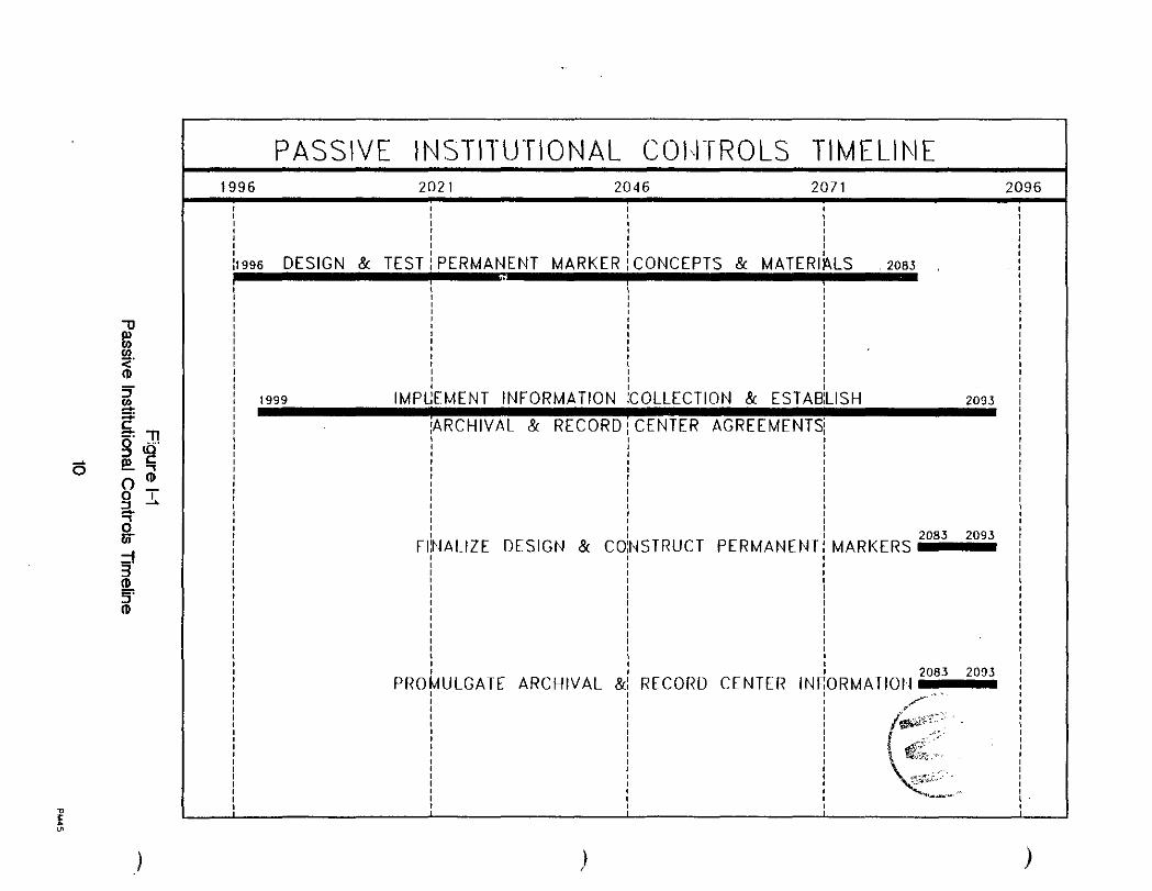
Although erection of the permanent marker system and establishment of archival and record center storage of information will not be initiated until after closure of the WIPP, see Figure 1-1 for the time line, design information and identification of archived/stored information is necessary to evaluate the efficacy of the Passive Institutional Controls (PIC), which in turn can be used in the demonstration of compliance. This conceptual design will be used as part of the 40 CFR 191 Compliance Certification Application and the No-Migration Variance Petition (NMVP) for disposal submitted to the Environmental Protection Agency (EPA).
The distribution of documents to archives, record centers, and other organizations for the preservation of knowledge of the WIPP, its location, the design of the disposal system, and the nature and hazard of the waste associated with intrusion can begin during the decontamination and decommissioning phases. At that stage of disposal operations, the total inventory of the waste stored at the site will be known and documented. The distribution of the volume of information intended for archives and record centers and the translation into the several official languages of the United Nations of a summary of the WIPP design, location, waste identification, and hazards associated with any intrusion activity will take several years.
B. Scope
This report describes the concept the DOE intends to
PASSIVE INSTITUTION?& CONTROLS DESIGN REPORT REVISION 0
implement in developing the detailed components of the PIC system. The DOE has a reasonable expectation that a sufficient number of components of the PIC described in this report will endure and be understood to provide future generations with a warning regarding the location, design, and contents of the disposal system during the entire regulatory time frame of 10,000 years. For details discussing the basis of this expectation and the quantitative credit used in the performance assessment see WIPP/CAO-96-3168, Effectiveness of Passive Institutional Controls in Reducing Inadvertent Human Intrusion into the Waste Isolation Pilot Plant for Use in Performance Assessments, May 1996. PIC will include a permanent marker system comprised of a large earthen structure marking the WIPP repository footprint on the surface, various messages, surface monument markers, small sub-surface warningmarkers, on-site rooms for long term storage of messages, archival storage of WIPP information off-site, and distribution of information to record centers and other entities for the preservation of knowledge of the WIPP. It should be noted that the illustrations used to support this conceptual design report are not intended to represent the final configurations. Rather they are for the purpose of - representing the type of configurations which are intended to be used in the final design. Much of the detailed permanent marker configuration is derived from concepts described in SAND92-1382, m e r t Judcnnent on Markers to Deter Inadvertent Ruman Intrusion into the Waste Isolation Pilot Plant, November 1993 (Trauth, et. al. 1993). Significant deviations from these described concepts are the result of practicability, constructability, and cost considerations. The participants in Trauth et. al., 1993 were under no constrictions regarding the scope of their considerations.
A single configuration for marking the controlled area described in the Land Withdrawal Act is discussed. Since the earthen structure is the most imposing feature of the permanent marker system, three separate concepts of the configuration of the earthen structures, arrangement of the monument markers, and placement of the storage rooms within the perimeter of the repository footprint are described. The first concept consists of a large earthworks configured in the shape of a trefoil centered above the repository surface footprint center. An Information Center is also placed at the center with large monuments arranged along the footprint's perimeter -',

PASSIVE INSTITUTIONAL CONTROLS DESIGN REPORT REV1810 kt&
and outside the trefoil. Two Storage Rooms are located east and west of the trefoil center. Each of these rooms are buried approximately 6M (20 feet) below the footprint surf ace.
A second configuration consists of a large earthworks configured as an earthen berm enclosing the footprint's perimeter. The large monuments are arranged just inside the berm along the footprint perimeter. In this configuration, an Information Center is located in the geographical center of the repository footprint. One Storage Room is buried at grade level under the center of the southern section of the berm and a second Storage Room is buried 6M (20 feet) below the surface 160M (525 feet) north of the center of the northern section of the berm. Small warning markers are buried throughout the footprint surface area.
The third concept is a 'menacing earthworks" (Trauth et. al., 1993) that includes several large earthen berm structures shaped individual like 'lightning" and arranged in a pattern. The structures I1radiate" out from the footprint perimeter as outlined by the monuments. The four corner sections are significantly larger than the other sections. Within each corner section is buried a Storage Room. The Information Center is located at the footprint center. Again, the small warning markers are buried throughout the footprint surface area.
The first and third earthen structure configurations are described since they represent ideas for earthen structures discussed by Team B and Team A in Trauth, et. al., 1993. The second configuration described previously is the concept intended for implementation and development of a preliminary design effort. The second configuration requires less material than either of the other two configuration and as described later provides some protective advantages over the other two configurations. When initiated, the preliminary design will include detailed planning for the testing of various materials and configurations over a period of several decades of WIPP operation and active control after closure.
All three earthwork configurations would be constructed in a similar manner as described later in this report. The testing effort is for the purpose of better understanding the long term chemical stability and
*... " P'-
~., ,
P ., . 'La
5 . ., , ( ", ,",, . .
'$! 'y;
PASSIVE INSTITUTIONAL CONTROLS DESIGN REPORT REVISION 0 ': ' - " I
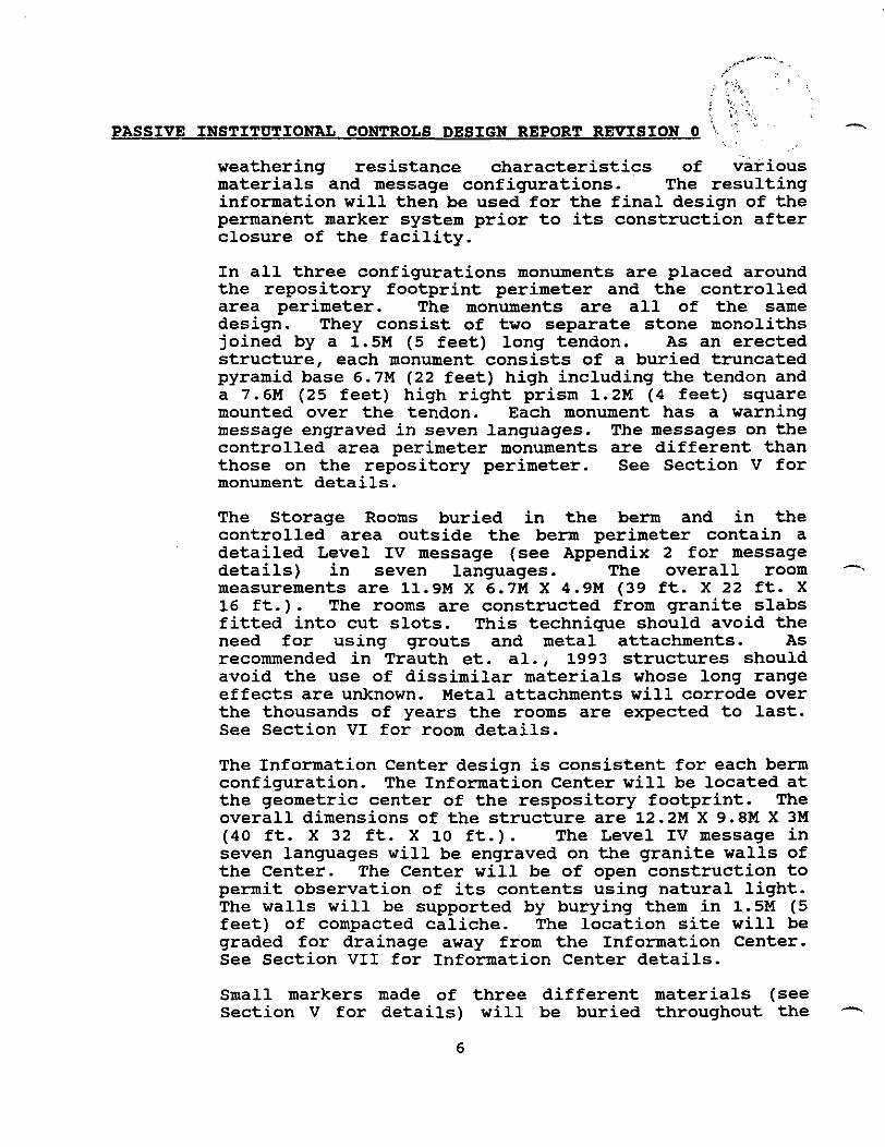
weathering resistance characteristics of various materials and message configurations. The resulting information will then be used for the final design of the permanent marker system prior to its construction after closure of the facility.
In all three configurations monuments are placed around the repository footprint perimeter and the controlled area perimeter. The monuments are all of the same design. They consist of two separate stone monoliths joined by a 1.5M (5 feet) long tendon. As an erected structure, each monument consists of a buried truncated pyramid base 6.7M (22 feet) high including the tendon and a 7.6M (25 feet) high right prism 1.2M (4 feet) square mounted over the tendon. Each monument has a warning message engraved in seven languages. The messages on the controlled area perimeter monuments are different than those on the repository perimeter. See Section V for monument details.
The Storage Rooms buried in the berm and in the controlled area outside the berm perimeter contain a detailed Level IV message (see Appendix 2 for message details) in seven languages. The overall room measurements are 11.9M X 6.7M X 4.9M (39 ft. X 22 ft. X 16 ft.). The rooms are constructed from granite slabs fitted into cut slots. This technique should avoid the need for using grouts and metal attachments. As recommended in Trauth et. al., 1993 structures should avoid the use of dissimilar materials whose long range effects are unknown. Metal attachments will corrode over the thousands of years the rooms are expected to last. See Section VI for room details.
The Information Center design is consistent for each berm configuration. The Information Center will be located at the geometric center of the respository footprint. The overall dimensions of the structure are 12.2M X 9.8M X 3M (40 ft. X 32 ft. X 10 ft.). The Level IV message in seven languages will be engraved on the granite walls of the Center. The Center will be of open construction to permit observation of its contents using natural light. The walls will be supported by burying them in 1.5M (5 feet) of compacted caliche. The location site will be graded for drainage away from the Information Center. See Section VII for Information Center details.
Small markers made of three different materials (see Section V for details) will be buried throughout the -,

PASSIVE INSTITUTIONAL CONTROLS DESIGN REPORT REVISION 0
repository footprint. Each marker will have a warni-ng message in one of the seven languages used on the monuments, Storage Rooms, and Information Center. The markers will be buried at randoms intervals over a range of 0.6M-1.8M (2-6 ft.) below the surface. Spacing will also be random. It is intended that some of the buried markers would be unearthed and serve as a warning to any individuals attempting to exploit resources via drilling and/or mining activities prior to their actually intruding into the repository.
This report also discusses the type of documentation to be provided to archives world wide; identifies record centers which will be provided design, location, and waste content information; and describes other passive institutional controls which will minimize the likelihood of inadvertent intrusion into the repository.
C . Background
Title 40 of the Code of Federal Regulations (CFR), Part 191 prescribes that disposal systems be designed and built such that they provide a reasonable expectation that for 10,000 years: 1) the undisturbed performance of the system will not result in an annual committed effective dose to any member of the public in excess of 15 millirem; 2) the levels of radioactivity in groundwater will not exceed limits specified by the standard in 40 CFR S191.24; and 3) the probability of releases from all significant processes and events acting on the disposal system will not exceed the specifications in 40 CFR §191.13(a). Appendix C to Title 40 CFR Part 191 states that inadvertent and intermittent intrusion by exploratory drilling for resources can be the most severe intrusion scenario assumed by the DOE. Subsequent to 40 CFR 191 promulgation, 40 CFR S194.32 also requires that performance assessment include mining as well as drilling. These human initiated intrusion events represents the greatest potential risk to release of the stored Transuranic (TRU) mixed waste into the environment. The primary goal of the PIC is to minimize the likelihood of inadvertent human intrusion.
Sandia National Laboratories (SNL) in its capacity as the scientific advisor to the DOE for the WIPP Project established two groups of experts to examine the issues involved with selecting, designing, and implementing an effective system of permanent markers. The result of their work was published as Trauth et. al., 1993. SNL

PASSIVE INSTITUTIONAL CONTROLS DESIGN REPORT REVISION 0 - charged these groups with the task of designing a 10,000- year marking system for the WIPP (Trauth et. al, 1993). 40 CFR S191.13 also specifies 10,000 years as the period of applicability of the containment requirements. Hora et al., Emert Judwent on Inadvertent Human Intrusion into the Waste Isolation Pilot Plant, SAND90-3063, December 1991 is the report by the Futures Panel (FP) discussing the "underlying physical and societal factors that would influence society and the likely modes of human-intrusion at the WIPP."
The FP members also developed probabilities of various alternative futures, of inadvertent human intrusion, and in some cases, of particular modes of intrusion. The report was an important reference and source of information for the follow-on group of experts when developing Trauth et. al., Emert Judwent on Markers to Deter Inadvertent Human Intrusion into the Waste Isolation Pilot Plant, SAND92-1382, November 1993. Trauth et. al. , 1993 reports the results of the two teams of experts, the Markers Panel (MP), who considered various concepts of marking the site and conveying to future generations information regarding the presence of dangerous waste material and the potential consequence of - intrusion into the waste repository. The conceptual design described in this report has used many of the concepts from Trauth et. al., 1993 and modified them to meet the practicality of construction and cost and the goal of being 'the most permanent markers, records, and other passive institutional controls practicable to indicate the dangers of the wastes and their location." as required in 40 CFR §191.14(c).
The testing described in Section IX will include the development of data regarding the long term durability of construction materials intended to be used in the Permanent Marker System. It is anticipated that this testing program will initiate during the disposal phase and continue on beyond decommissioning into the Active Controls phase. During the Active Controls phase periodic evaluation of test structures will be conducted. Actual construction of the Permanent Marker System will be delayed for some decades after decommissioning to provide sufficient time to effectively evaluate the long term durability of the various construction materials and the effects of weathering on monument markers and a section of berm.
,- PASSIVE INSTITUTIONAL CONTROLS DESIGN REPORT REVISION 0
Duringthe decontamination and decommissioning phase, the DOE will assemble descriptive material to be archived, assemble descriptive material to be provided to record centers, develop the WIPP descriptive summary document, and develop the indexing system to be used by archive locations in their storing of the WIPP material. In addition during this period, the DOE will establish agreements with the proposed archival and record center locations identified in Sections XIV and XV to ensure that the planned locations are willing to accept the information to be promulgated. Distribution of these materials will be accomplished duringthe Active Controls phase of the WIPP project. Action to implement other passive institutional controls as described in Section XVI will also be taken upon completion of decommissioning. The time lines for implementation of the PIC are shown in Figure 1-1.
PASSIVE INSTITUTIONAL COI\lTROLS TIMELINE
RECORD CENTER IN
ISH 7097
2083 2093 MARKERS -

!'
- PASSIVE INSTITUTIONAL CONTROLS DESIGN REPORT REVISION 0
11. SITE DESCRIPTION
The WIPP facility has been constructed 42 kilometers (26 miles) east of Carlsbad, New Mexico in southeastern New Mexico's Eddy County. The site, occupying 4144 hectares (10,240 acres or 16 sections), was withdrawn from the public domain in October 1992 by the Waste Isolation Pilot Plant Land Withdrawal Act (LWA) (Public Law 102- 579). This law places jurisdiction of the land in the hands of the Secretary of Energy. The area surrounding the site is sparsely populated with about 27 people living within 16 kilometers (10 miles). The activities in the general area are primarily devoted to livestock grazing, potash mining, and oil and gas development. Figure 11-1 shows the general location of the WIPP site.
The surface physiography of the land in the immediate WIPP vicinity is that of sand dunes from which the area gets its name, Los Mendaiios. The area within the waste disposal area footprint is punctuated with dunes up to approximately 3M (10 feet) high. The dunes have been stabilized primarily by Harvard Shin Oak which has an extensive root structure to limit the wind effects on the sand dunes. The Kermit-Berino soils, which include the active dunes areas, have been uraniup-trend aged at 330,000+75,000 years. The sand is underlain by the Mescalero caliche layer. According to Bachman 1985, where the Mescalero is flat-lying and not breached by erosion, the caliche is an indicator of stability or integrity of the land surface over the last 500,000 years. The caliche is dense and impervious, WP 02-9, 1990.
The surface facilities provide security and safeguards, accommodate routine operations, provide administrative and management facilities, and support on-going scientific studies. These facilities are designed to service full-scale operations and have undergone extensive testing and operational review. The waste handling building is the principal surface structure dedicated to supporting the handling of TRU waste containers and their transport to the underground. The building shelters the facilities for receiving Contact Handled (CH) TRU waste containers within the Nuclear Regulatory Commission certified Transuranic Package Transporter-I1 (TRUPACT-11), unloading the TRUPACT-11, inspecting the waste containers, and preparing the containers for transfer to the underground repository. The building also shelters facilities for receiving

PASSIVE INSTITUTIONAL CONTROLS DESIGN REPORT REVISION 0
Remote Handled (RH) TRU waste in canisters and shielded casks. The building is divided into two (2) major areas. One area is for receipt and inspection of CH TRU waste and the other area is dedicated to the receipt and inspection of RH TRU waste. A single waste shaft is designed integral with the waste handling building to transport either CH or RH TRU waste containers to the underground repository. Within the RH TRU waste area is the Hot Cell. The Hot Cell provides a radiation shielded facility for unloading and manipulating containers of radioactive waste with surface radiation dose rates of up to 1000 Rem/hr. The Hot Cell is constructed of concrete walls 4.5 feet thick and extending 60 feet above grade. The Hot Cell basement extends approximately 20 feet below the grade level. It is planned as part of this conceptual design that the concrete Hot Cell will remain as an archeological monument after decommissioning the WIPP site.
External to the waste handling building and the waste shaft are additional buildings and three (3) shafts. The major buildings are the support building, the safety and emergency services facility, the engineering building, the training building, the warehouse/shops building, and - the core storage building. A number of temporary buildings and trailers are also used to support various operational, maintenance, technical, and administrative functions.
The salt handling shaft, located north of the support building, is used for transport of personnel to and from the underground, for transporting mined salt from the underground, and as a secondary source of air to the underground. An air intake shaft provides the primary source of air into the underground ventilation system. An exhaust shaft with two normal ventilating fans and three emergency fans provides for the forced ventilation of the entire underground area. The three emergency fans exhaust through a bag house containing particulate filters to mitigate the release of radioactive particulate in the unlikely event that such material is released in the underground storage area.
In the underground, to the north of the shafts, is the Experimental Area. This 4.8 hectares (12 acres) area was dedicated to conducting scientific investigations and experiments. This area is being deactivated in 1996 with completion of the planned investigations and experiments within the underground repository. To the south of the -'

- PASSIVE INSTITUTIONAL CONTROLS DESIGN REPORT REVISION 0
shafts is the Waste Disposal Area. The eight (8) panels and associated entries to be used for waste disposal have an area of approximately 48.5 hectares (120 acres). The main entries- provide access and ventilation. Certain entries near the shafts are used for operational and maintenance activities. Connecting the Experimental and Waste Disposal Areas are four (4) major interconnecting drifts (tunnels) used for ventilation and traffic.
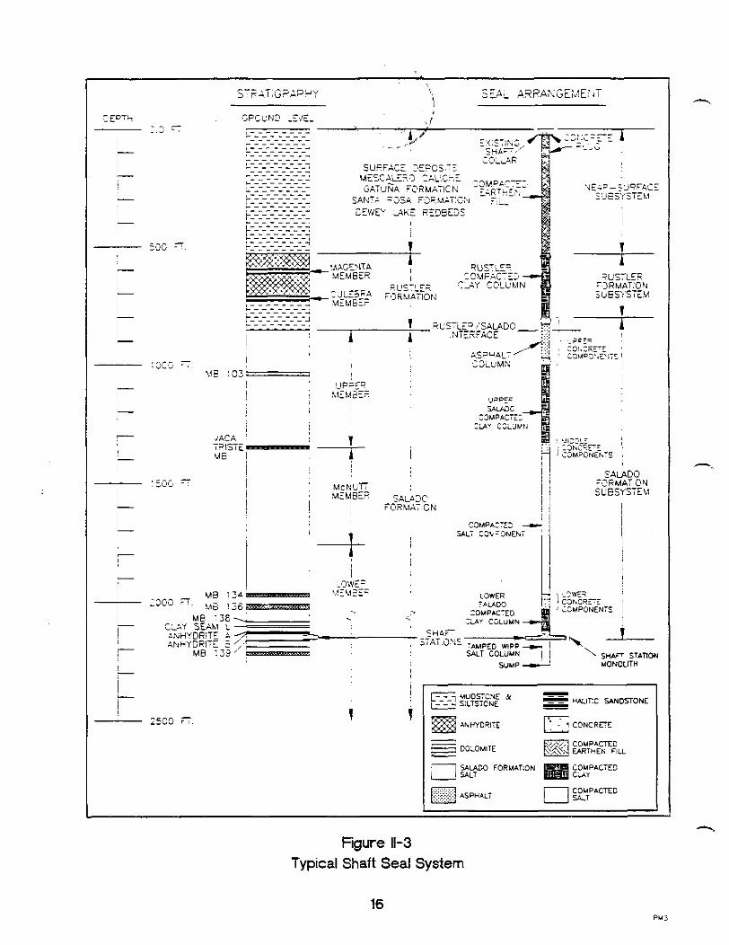
Each of the eight (8) panels (only Panel 1 is currently mined) is planned to be comprised of 7 rooms. The nominal excavated dimensions of the individual rooms are 300' X 33' X 13'. Panels 9 and 10 consist of the main entries between Panels 1-4 and 5-8. The designed storage capacity of the repository is 6,200,000 ft" CH TRU waste will be contained in individual Standard Waste Boxes (SWB) or 55 gallon drums arranged in 7-packs. The SWBs and 7-packs will be stacked in the waste disposal rooms. Containers will also be emplaced within the panel entries of each panel. Individual panels will be closed as they are filled and upon final closure of the repository, the shafts will be plugged and sealed over their entire lengths. Figure 11-3 illustrates a shaft plugging and sealing configuration, Nowak 1990. The figure is also Diagram 1 of the of the Level IV message text described later.

To Jal --L a;-
Pecos Rlver i 14
New Mexico
Texas w
Figure 11-1 General Location of the WlPP Facility

' ~ 1 l A l 1 1'11 I A R AREA ~ ~ G!,') MI I 1 I<., Ill 11'
- UUDSTCNE JL 5 - SLisTCNE m HMlTlC YNDSTONE
AHHYDRITE CONCREE
DOLOMllE
% W O FORMA?ION SALT
COMPACTED CAY
Figure 11-3 Typical Shaft Seal System
16
PASSIVE INSTITUTIONAL CONTROLS DESIGN REPORT REVISION 0
111. DESIGN REOUIREMENTSICRITERIA
Trauth et. al., 1993 discusses at length the processes used to form. the expert panel which developed SAND92-. 1382. The panel was divided into two teams, Team A and Team B. Each team then developed its philosophy for passing messages on to future generations. Appendix 1 is the table from Trauth et. al., 1993 comparing the Marker System Components developed by each team. As can be seen from a review of the table, some differences existed between the teams. Drawing on information found in the table and a review of the individual team reports documented in Trauth et. al., 1993, the following principles were applied to guiding the conceptual permanent marker design:
a The site is marked a Message(s) are truthful and informative a Multiple components exist within a marker system a Multiple means of communication (e-g., language,
pictographs, scientific diagrams) are provided a Multiple messages with differing levels of
complexity between messages are inscribed on individual marker system elements
a Materials with little recycle value are used Compliance with international standards of marking locations and contents of nuclear waste repositories
All but the last of these principles have been followed to the extent practicable in this concept design document. The last principle, while laudatory is not achievable at this point in time. No international standards exist. If, in the future, standards are developed and adopted by the United States, they will be evaluated for incorporation as appropriate in preparing the final permanent marker design.
The following design requirements were developed by Westinghouse in support of the Carlsbad Area Office (CAO) of the DOE from a review of Trauth et. al., 1993 and the applicable regulations. Each of the requirements has been addressed in the development of the design criteria.
a The marking system should provide a reasonable expectation that the site will be uniquely marked and such marking will be the most permanent practicable. The system must also provide for marking the controlled (withdrawn) area. It is
PASSIVE INSTITUTIONAL CONTROLS DESIGN REPORT REVISION 0 .1
recognized that experience gained during the first 100 years may result in marker system modifications to improve the endurance capability of the system BASIS: Title 40 CFR Part 191, 40 CFR 194, and Trauth et. al., 1993. The period of regulatory interest is 10,000 years.
a The site must be marked in such a manner as to provide reasonable assurance that the marker's purpose cannot be mistaken or its intended message misinterpreted. The system should include a combination of surface and subsurface markers BASIS: Trauth et. al., 1993. Expert panel . judgement to account for possible removal of surface markers and effects of erosion for uncovering subsurface markers
The marking system must include the concept of "defense in depthw which implies redundancy by way of its physical design and message delivery concepts BASIS: Trauth et. al., 1993. Expert panel judgment and a common design philosophy of the nuclear electric generating station industry.
a Materials comprising the marking system should have as little intrinsic value as is reasonable to minimize the likelihood of future generations salvaging the material for recycling purposes BASIS: Trauth et. al., 1993. Expert panel judgment.
The marking system on the surface should encompass the grade level equivalent of the entire waste storage footprint (waste filled panels and drifts) but not exceed the footprint by more than 10% in area BASIS: Trauth et. al., 1993 and engineering judgment. Expert panel judgment that the marker system extent should be limited to the repository footprint so as not to give false sense of the hazard if deep drilling is conducted outside the footprint with no hazardous material encountered. Engineering judgment to provide a 10% margin to allow for construction of the berm encompassing the repository footprint perimeter which is marked by the granite monuments.
a The message delivery components should provide a

PASSIVE INSTITUTIONAL CONTROLS DESIGN REPORT REVISION 0
means of communicating with reasonable expectation the what, when, who, why, and how essentials of the WIPP program to future generations and should include an assortment of symbolic, pictographic, linguistic, narrative, diagrammatic, scientific, and astronomic messages BASIS: Trauth et. al., 1993. Expert judgment.
The marker system should be constructible with available technology and its construction should be cost effective BASIS: Engineering judgment in response to the Title 40 CFR 191 requirement to provide the most permanent markers practicable (emphasis added).
Information regarding the location, design, contents, and hazards associated with the WIPP should be archived domestically and internationally so as to be accessible by individuals or organizations having an interest in exploiting potential resources at the WIPP site. BASIS: Title 40 CFR 194 and Trauth et. al., 1993. Expert judgment.
Development of the design criteria applicable to the permanent marker system included adherence to the guidelines and design requirements addressed above. Design criteria were established to:
1. Provide a system for marking the disposal area footprint on the surface through use of berms and monuments:
Berm dimensions should be a minimum of 30M (100 feet) at the base and a minimum 10M (33 feet) high. BASIS: Trauth et. al., 1993. Expert judgment (Team B) . Berms should be massive to withstand human and natural forces. Slope needs to accommodate a roadway on the surface to facilitate construction.
Berm slope should be at least 1.3 horizontal to 1.0 vertical. BASIS: Trauth et. al., 1993. Expert judgment (Team A) . Slope of a natural talus is 1.3 to 1.0. Any steeper slope may significantly impact effects of erosion.
PASSIVE INSTITUTIONAL CONTROLS DESIGN REPORT REVISION 0
Berm should be mechanically packed. BASIS: Provides for a more stable and reduces slumping with time.
structure
Berm should provide a dielectric or magnetic anomaly when compared to the local surface characteristics. BASIS: Trauth et. al., 1993. Expert judgment. Provide a capability for marker detection by electronic means as part of the defense in depth concept.
a Configuration of the berm marker should provide for observation of the entire marked area from any point on top of the berm adjacent to the marked area. BASIS: Trauth et. al., 1993. Expert judgment.
a To the extent practicable local material should be used for the majority of the berm structure BASIS : Trauth et. al., 1993. Expert judgment. I
a Monuments should be at least 7.5M (25 feet) high BASIS : Trauth et. al., 1993. Expert judgment. Monuments should be high enough not to be covered by migrating dunes.
a Monuments should include a minimum 20 tons continuous mass (no bonding materials between components for individual monuments) BASIS: Trauth et. al., 1993. Expert judgment. Monuments should be sufficiently massive to minimize the effects of vandalism or removal. Bonding materials of different chemical composition than the monuments material may have long term detrimental effects on the monument material.
a The total number of perimeter marking monuments should be a power of 2. BASIS : Trauth et. al., 1993. Expert judgment. Provide a sufficient number of monuments to permit future societies to reconstruct original monument configuration.
-\

. .. !.? J . , <
: .:;,tr :% ,? .-. PASSIVE INSTITUTIONAL CONTROLS DESIGN REPORT REVISION 0 '...: *" ',J
The spacing between monuments should be such that an average individual standing adjacent to one monument will be able to see the monuments on either side. BASIS: Trauth et. al., 1993. Expert judgment.
To the degree practicable, monument material should be relatively unaffected by anticipated environmental and climatic conditions. BASIS: Trauth et. al., 1993. Expert judgment . Minimize the risk of adverse environmental affects.
The monument messages shall be engraved to a depth of at least lcm. BASIS: Engineering judgment for longevity of engraved messages in granite. Birkeland, 1984 reports weathering rinds of granitic rocks in the Central Sierra Nevada, CA at 1.7 mm at a 10,000-20,000 year estimated age.
Place subsurface warning markers throughout the disposal area footprint:
Warning markers shall be less than 0.6M (2 feet) in the longest dimension. BASIS: Engineering judgment. Sufficient size to carry a warning message but not represent individually a major emplacement effort.
Marker material should be inert with respect to the local environmental conditions at the depth at which they are buried. BASIS: Trauth et. al., 1993. Minimize the potential of marker degradation from chemical attack.
Burial depth should be greater than deep plowing/tilling or that expected to be dug by amateur archaeologists BASIS: Trauth et. al., 1993. Minimize loss due to inadvertent uncovering or vandalism.
The warning message shall be written in Spanish, English, Russian, Chinese, French, Arabic, and Navajo. Distribution of the seven languages should be evenly spread among all the buried warning markers.
PASSIVE INSTITUTIONAL CONTROLS DESIGN REPORT REVISION 0 c.l.
BASIS: Trauth et. al., 1993. Expert and engineering judgment.
0- Marker spacing should be such that their discovery has a high probability under conditions currently anticipated to be created by drilling crews and professional archaeologists. However, spacing should be random to minimize excessive loss through vandalism and/or souvenir collection efforts. BASIS: Trauth et. al., 1993 and engineering judgment .
Provide for detailed, complex information storage:
Structures for the permanent storage of detailed and complex information relating to the repository location, contents, and associated hazards shall be constructed. BASIS: Trauth et. al., 1993. Expert judgment.
0 Buried and surface structures shall be provided. -. BASIS: Trauth et. al., 1993. Expert judgment. Provide a reasonable expectation that complex information is available through redundancy and varying locations.
The structural material shall be inert and sufficiently durable to provide a high degree of protection for the stored information. BASIS: Trauth et. al., 1993 and engineering judgment.
Stored written records, tables, figures, graphs, maps, and diagrams shall be engraved in stone or man-made materials having the durability to retain the engraved information over extended periods of time. BASIS: Trauth et. al., 1993 and engineering judgment based upon ancient analogues of stone structures (e-g. Stonehenge, the Pyramids, the Acropolis) . Entry to buried structures shall be designed to preclude removal of the stored information by curious individuals. Removal should require a concerted effort by a well financed -.

1 PASSIVE INSTITUTIONAL CONTROLS DESIGN REPORT REVISION 0
and technically competent organization. BASIS: Trauth et. al., 1993 and engineering judgment.
Concrete for encasement of radar reflectors and berm stairway shall be in accordance with the Building Code requirements for Reinforced Concrete (ACI-3 18, latest edition) with special emphasis on durability, (ACI-201.2, Guide to Durable Concrete). BASIS: Engineering judgment.
PASSIVE INSTITUTIONAL CONTROLS DESIGN REPORT REVISION d -
IV. MESSAGES
Five levels of messages will be used in the Permanent Marker System as recommended in Trauth et. al., 1993.
Message level I conveys the information that the site is manmade. The message itself is in the physical form of the marker system and the effort expended in constructing it.
0 Message level I1 conveys the cautionary information that something manmade is here and it is dangerous. That the dangerous material is buried is conveyed in the cautionary prohibition against digging or drilling. This message is carried in seven languages uniformly distributed among the subsurface warning markers. Each marker has the message in a single language. The level I1 message is also engraved on each footprint perimeter monument in seven languages. The controlled area boundary markers caution against drilling or mining within the controlled area.
Message level I11 conveys basic information that - tells what, why, when, where, who, and how. This message is engraved on the footprint perimeter monument markers.
Message level IV conveys complex information in seven languages. The message is a highly detailed written record of the WIPP repository and includes tables, figures, maps, and diagrams. This message is contained in the Information Center, in the room buried within the berm, and in the room buried within the controlled area outside the repository footprint.
0 Message level V is archival and stores a complete rulemaking record. It is more detailed and voluminous than the messages provided at the WIPP site. This record is not stored at the site but shall be located in various archives at the state, federal, and international levels. A less detailed version of this record addressing location, design, hazards, testlexperiment results, and pertinent site data will be located in record centers at the local, state, and federal level.
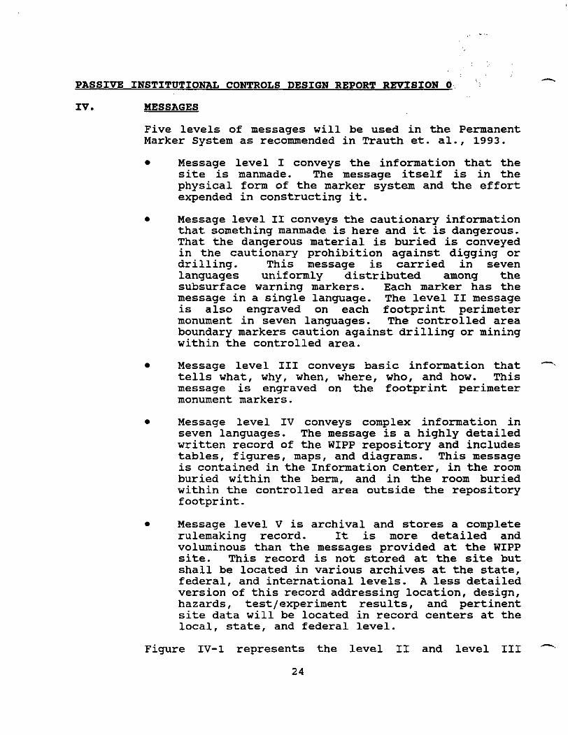
Figure IV-1 represents the level I1 and level I11

-. PASSIVE INSTITUTIONAL CONTROLS DESIGN REPORT REVISION 0
messages. Appendix 2 contains the level 11, 111,- and IV message text in English. During the final design phase, the messages will be translated into the other six languages. Testing of the messages1 ability to convey their intent to inform the public about the danger of intruding into the repository will be tested among populations indigenous to the language's locale.
The Level I message consists of the berm and surface structures delineating the controlled area boundary and the repository footprint boundary. The monuments, Information Center, and buried Storage Rooms provide the surfaces upon which upon which to engrave the Level 11, 111, and IV messages. The Level I message includes the earthen berm, the granite monuments, and the information center. The physical size of these structures should clearly convey the notion that the marker system is a manmade facility which required a significant amount of effort to construct, Trauth et. al., 1993. This should provide the inspiration for any organization with sufficient resources to dismantle the surface structures to investigate and attempt to understand the purpose of the site prior to initiating activities which are counter to maintaining the site's integrity. Individuals intent on vandalism or artifact collection may cause some superficial damage. However, due to the size of the structures and the physical attributes of granite, it is very doubtful that they could significantly reduce the structures sufficiently to destroy the implication that something manmade occupies the site.
The Level I1 and I11 (Figure IV-1) messages are engraved on the granite monuments outlining the repository footprint perimeter. The Level I1 message is a warning of danger. The graphic symbols from Trauth 1993 accompanying the "DANGER" warning are meant to convey:
- Horror and terror
@ - Something nauseating or poisonous
The danger is defined by the description that waste is both poisonous and radioactive. The Trefoil symbol (9) is used throughout the messages in association with the
PASSIVE INSTITUTIONAL CONTROLS DESIGN REPORT REVISION 0
terms "radioactivet@ and @tradioactivity@l. Its use in association with these terms should provide the interpretive definition of the symbol's significance. This would seem to be more appropriate than attempting to define the symbol narratively. The Biohazard symbol is shown along with the Trefoil on the monuments and the small subsurface warning markers as indicated in Figures V-1, V-2, and V-3. Finally the Level I1 message admonishes the reader not to dig or drill. Figure IV-1 illustrates the three part Level I1 message. Part 1 is the large 'DANGER" caution. Part 2 is the message cautioning not to dig or drill because of the radioactive waste. Part 3 is comprised of the facial expressions described above.
The Level I11 message, also illustrated in Figure IV-1, provides more definition with respect to what is buried, the size of the area in which digging or drilling should be prohibited, and the depth at which the radioactive waste is located. Readers of this message will also be made aware of when the WIPP was closed and the fact that there was an intent to preserve the warning information for 10,000 years. Included in this message is a request that the reader take action to update the message or the -.
marker system to add long lasting materials and/or messages written in languages more current to the times. The design of the monuments provide sufficient blank surface areas for the addition of messages in other languages. It is anticipated that over time the languages will change such that they may become incomprehensible to the general public and only scholars will be able to interpret their meaning.
The Level I1 and I11 messages closely follow the recommendations from Trauth et. al., 1993. In addition, two diagrams are included on the perimeter monuments. These diagrams should mitigate the effects of language changes in conveying the cautionary message. As described below one diagram is meant to pictorially convey the danger of digging or drilling into the repository. The second diagram (from Trauth et. al., 1993) is meant to provide an ability to determine how long it has been since the WIPP was closed and convey the decreasing nature of the danger over a period of thousands of years.
Jensen 1993 provides an example of how quickly (relative to 10,000 years) the English language has changed by
1
providing the following quote from Sir Gawain and the Greene Knight (unknown author written about 1375 AD-less than 650 years ago) :
The stele of a stif staf the sturne hit bi gripte That was wounden with iron to the wandes ende, And a1 bigraven with grene in gravios werkes.
In the modern English this quote is written as:
The grim man gripped it by its great strong handle, which was wound with iron all the way to the end, and graven in green with graceful designs.
With the advent of printing and more recently the advancement of worldwide communication the rate of change of language has probably slowed considerably. With increased use of the English language for business, its rate of change will most likely be even further reduced. Notwithstanding these circumstances, the messages are being presented in a variety of languages to improve the likelihood that their meaning will be understood by future generations. A monument with its messages in 7 different languages is a modern Rosetta stone. However, unlike the Rosetta stone, the size of each monument is such that it is not likely a monument will be moved to some remote location in order to be studied and interpreted. Rather the interpreters will need to record the messages for study and even if the study activity does occur elsewhere, the fact that the original messages are not moved from the site should enhance the probability that the interpreted results will be made known at the site.
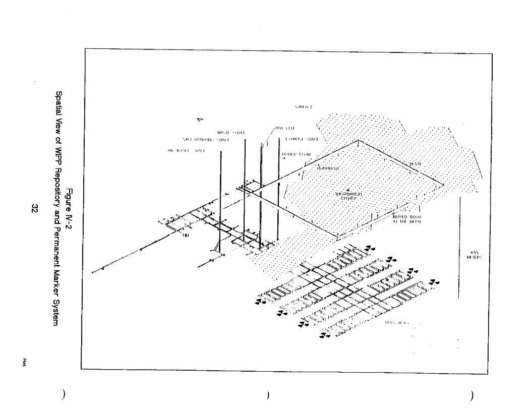
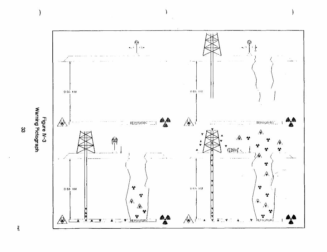
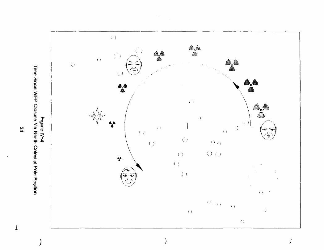
Figure IV-2 shows the spatial perspective of the marking system to the repository and the underground shafts which supported the repository during its construction, operation, and closure. Figures IV-3 and IV-4 are a part of the Level I11 message. Figure IV-3 is a cartoon showing the spatial perspective of the marking system to the underground repository. It depicts as a warning a sequence of activities which lead to releasing the waste from the repository and causing death to the individual digging or drilling down to the repository level. Figure IV-4 (Diagram 6 of the message text in Appendix 2) provides the skilled and technically knowledgeable reader a method to determine independently when the repository was closed after waste emplacement. The constellation formations for Ursa Minor, Draco, Cygnus, Ursa Major, and
PASSIVE INSTITUTIONAL CONTROLS DESIGN REPORT REVISION 0'. " - the brightest star, Vega are shown with respect to the precession of the north celestial pole of thousands of years. The reader can estimate when the repository was closed by comparing the pole position at closure to its position at the reader's time. The decreasing size of the (Trefoil) is shown to convey the idea that the amount of radioactivity is decreasing with time. The faces (from Trauth 1993) show disgust at the time of closure to neutral at 10,000 years and contentment well beyond 10,000 years.
The Level IV message is the most comprehensive and complex message located at the WIPP site. Appendix 2 provides the text of the Level IV message (derived from Trauth et. al., 1993) which will be translated into the seven languages in which it is to be presented. The text portion of the Level IV message expands upon the brief Level I11 message. In particular the Level IV message provides the following details:
It describes the potential leakage path for radioactive material through ground water should deep drilling occur
1
It specifies the disease cancer as the potential human impact from radiation poisoning and explains that cancer is a long term result
It specifies the particular radioactive isotopes, their individual quantities, and the hazardous chemicals which were originally buried
It identifies that the U.S. Government was responsible for this long term solution of isolating waste derived from its nuclear weapons making activities
It describes why the Salado formation was chosen as the repository site
0 It describes the general layout of the repository and the original configuration of the emplaced waste
It provides an explanation of the Trefoil and Toxic symbols -.
fi PASSIVE INSTITUTIONAL CONTROLS DESIGN REPORT REVISION 0
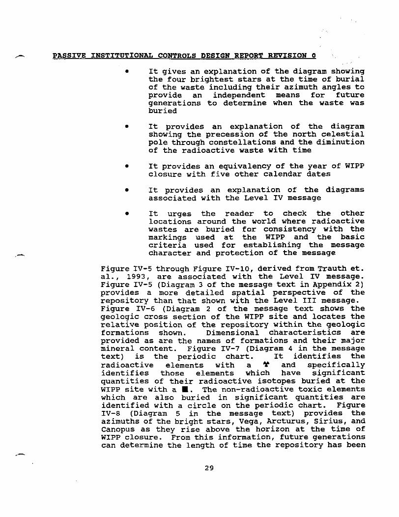
0 It gives an explanation of the diagram showing the four brightest stars at the time of burial of the waste including their azimuth angles to provide an independent means for future generations to determine when the waste was buried
0 It provides an explanation of the diagram showing the precession of the north celestial pole through constellations and the diminution of the radioactive waste with time
0 It provides an equivalency of the year of WIPP closure with five other calendar dates
It provides an explanation of the diagrams associated with the Level IV message
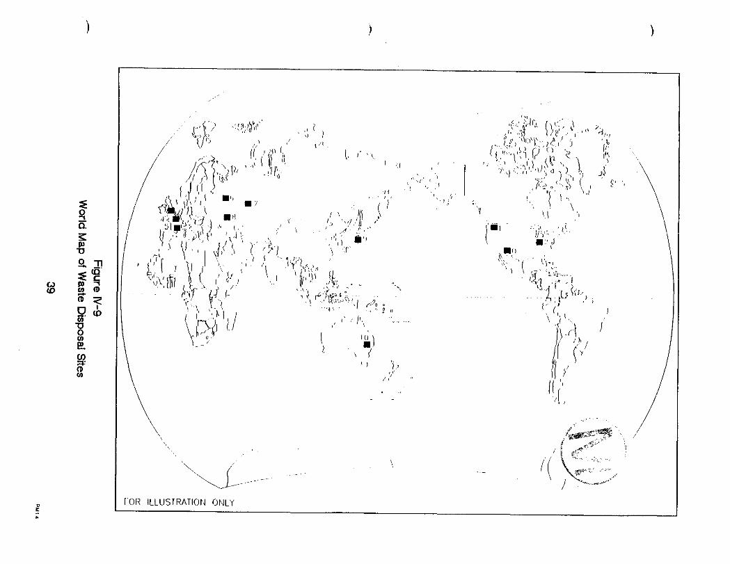
It urges the reader to check the other locations around the world where radioactive wastes are buried for consistency with the markings used at the WIPP and the basic criteria used for establishing the message character and protection of the message
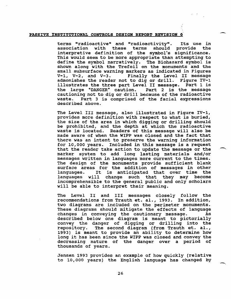
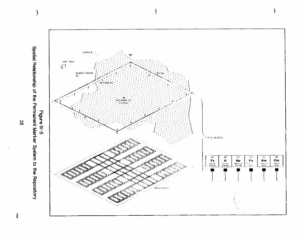
Figure IV-5 through Figure IV-10, derived from Trauth et. al., 1993, are associated with the Level IV message. Figure IV-5 (Diagram 3 of the message text in Appendix 2) provides a more detailed spatial perspective of the repository than that shown with the Level I11 message. Figure IV-6 (Diagram 2 of the message text shows the geologic cross section of the WIPP site and locates the relative position of the repository within the geologic formations shown. Dimensional characteristics are provided as are the names of formations and their major mineral content. Figure IV-7 (Diagram 4 in the message text) is the periodic chart. It identifies the radioactive elements with a * and specifically identifies those elements which have significant quantities of their radioactive isotopes buried at the WIPP site with a .. The non-radioactive toxic elements which are also buried in significant quantities are identified with a circle on the periodic chart. Figure IV-8 (Diagram 5 in the message text) provides the azimuths of the bright stars, Vega, Arcturus, Sirius, and Canopus as they rise above the horizon at the time of WIPP closure. From this information, future generations can determine the length of time the repository has been

PASSIVE INSTITUTION= CONTROLS DESIGN REPORT REVISION 0 ?,
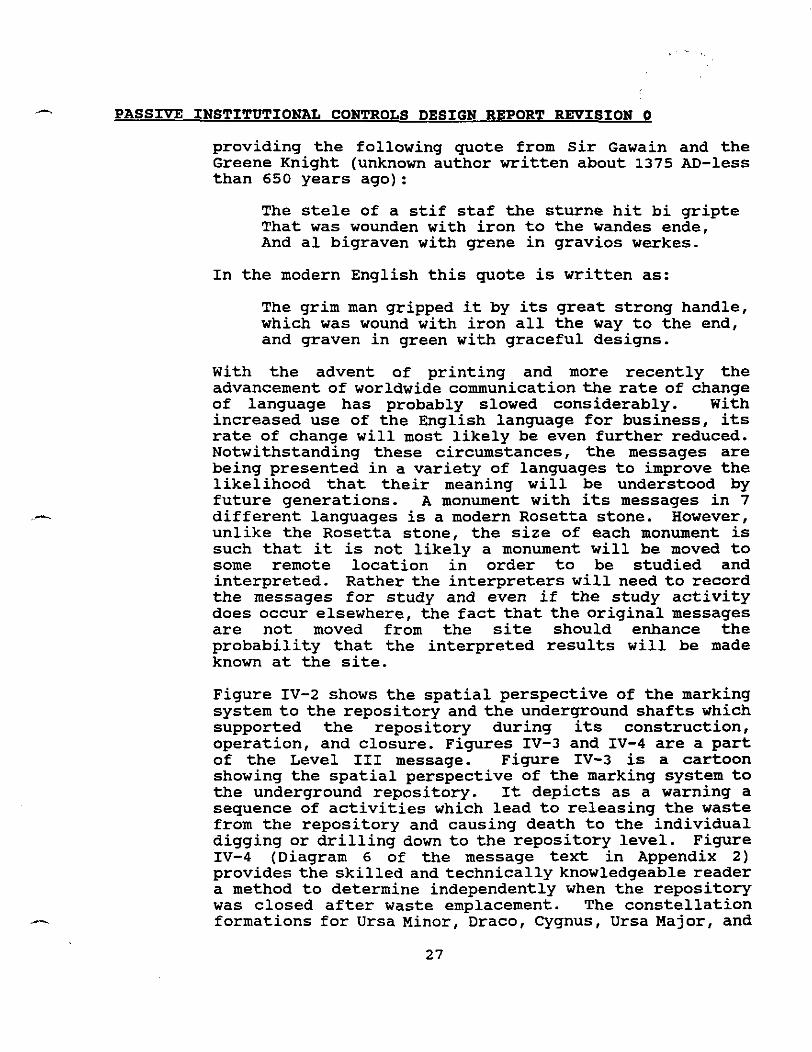
closed. Figure IV-9 (Diagram 7 in the message text) is a world map showing the locations throughout the world where radioactive wastes are buried (the locations shown are examples and not necessarily where the wastes will be buried at the time that the WIPP is closed). The W symbol is used to identify that "Radioactive Waste Is Buried Here." Figure IV-10 (Diagram 8 in the message text) is comprised of two circles as described in Trauth et. al. , 1993. The numbers corresponding to the dots refer to the buried waste storage locations shown on the world map. The outer circle provides the longitudinal position of the storage locations relative to the WIPP. The inner circle provides the latitude of the storage locations relative to the WIPP. According to Trauth et. al., 1993, if circles approximately 3 M in diameter are used and the positions are placed with an accuracy of lmm, the locations of the storage sites can be located to within 4 km. The Figure IV-8 circles are 3.OM (9.84 feet) and 2.9M (9.1 feet) in diameter to permit the latitude circle to fit inside the longitude circle. The design of the Information Center and the buried Storage Rooms containing the Level IV message accommodate both the map and the latitude/longitude circles.
I

POISONOUS RADIOACTIVE .C WASTE HERE ! ."-El
DO NOT DIG OR DRILL r. y"4J
AND HAZARDOUS MATERIALS. THE AREA IS 660 BY 810 METERS AND THE WASTE IS BURIED 655 METERS DOWN. THlS PLACE WAS CHOSEN TOPUT THESE DANGEROUS MATERIALS FAR AWAY FROM PEOPLE AND OTHER LIVING THINGS. THE ROCK AND WATER IN THlS AREA MAY NOT LOOK. FEEL, OR SMELL UNUSUAL, BUT MAY BE POISONED BY RADIOACTIVEYWASTES AND HAZARDOUS MATERIALS. WHEN RADIOACTIVE.I.MATTER DECAYS, IT GIVES OFF INVISIBLE ENERGY THAT CAN DESTROY OR DAMAGE PEOPLE, ANIMALS, AND PLANTS.
DO NOT DRILL HERE. DO NOT DIG HERE. DO NOT DO ANYTHING WITH ROCKS OR WATER IN THE AREA.
DO NOT DESTROY THlS MARKER. THlS MARKING SYSTEM HAS BEEN DESIGNED TO LAST 10,000 YEARS. IF THE MARKER IS DIFFICULT TO READ. ADD NEW MARKERS COMPOSED OF LONGER-LASTING MATERIALS AND COPY THlS MESSAGE IN YOUR LANGUAGE ONTO THEM.
THE SlTE WAS KNOWN AS THE WlPP (WASTE ISOLATION PILOT PLANT) SlTE WHEN IT WAS CLOSED IN 2030. A.D. FOR MORE INFORMATION, GO TO THE BUILDING AT THE CENTER OF THlS MARKED AREA. IF THE MESSAGES WITHIN THE INFORMATION CENTER ARE UNUSABLE. THEY HAVE BEEN DUPLICATED IN A ROOM BURIED 6 METERS DEEP 160 METERS NORTH OF THE BERM ON A LINE PASSING THROUGH THE INFORMATION CENTER. THE CENTER OF THE NORTH AND SOUTH SECTIONS OF THE BERM, AND THE HOT CELL CONCRETE ARTIFACT STANDING APPROXIMATELY 320 METERS NORTH OF THE BERM CENTER LINE. THE ROOM LOCATION IS ALSO MARKED BY A MAGNETIC SIGNATURE. DO NOT EXPOSE THlS ROOM UNLESS THE INFORMATION CENTER - - - - - .~.. ~
MESSAGES ARE LOST. LEAVE THE ROOM BURIED FOR FUTURE GENERATIONS. IF THE ROOM BECOMES EXPOSED, PROTECT I T BY ADDITIONAL COVERING.
Figure N-1 Level II and Level Ill Messages

GENERALIZED GEOLOGIC CROSS-SECTION
SW NE
GROUND SURFACE
G A T U ~ A FORMATION SURFICIAL DEPOSITS
2 w
SEA LEVEL
b.4 - REPOSITORY LEVEL FORMATION
BELL CANYON FORMATION
I . I , SAND AND SANDSTONE 'B ANHYDRATE - b - - SILT STONE AND SANDST ONE -1 HALITE
-.---. , - - .-.- MUDSTONE AND SILTSTONE , , ; LIMESTONE
Figure N-6 Generalized Geologic Cross-Section

FIT- Od Tb
I." ..,," *".d..i. 1 .... "rn 11 ,.,.... 111.. 1,81> 111.1 I,,,,,

-OR ILLUSTRATlOlJ ONLY

NOT TC SCALE
Figure IV-10 Longitude and Latitude of Disposal Sies Relative to WlPP at "O'

C PASSIVE INSTITUTIONAL CONTROLS DESIGN REPORT REVISION 0
V. MONUMENT MARKERS
Monument markers are those elements of the marker system consisting of large monoliths (Kaplan, 1982) on the surface and small warning markers buried throughout the repository footprint. The material of choice for the monuments is granite. Trauth et. al., 1993 suggests basalt or granite. In a discussion with a number of commercial rock quarries (e.g. Rock of Ages, Bear VT: Harmony Blue Granite, Elberton, GA; and Cool Springs Granite Co., Marble Falls, TX) no source of large basalt monoliths were identified. To facilitate fabrication and shipping of the monuments, each monument will consist of two separate stones connected by a tendon joint. The large monuments erected around the perimeter of the repository footprint will be engraved with level I1 and I11 messages;. The large monuments erected around the perimeter of the controlled area (area defined by the LWA) will be engraved with the message in Appendix 3.
Figures V-1 and V-2 provide the dimensional characteristics of the large monuments. The conceptual configuration represent a simple design for ease of fabrication. Quarries contacted regarding the feasibility of producing large monoliths stated that fabrication of stone with flat surfaces were significantly simpler to quarry than those with curved surfaces. The wastage of material (and thus cost) is also significantly less for flat surface stones. Thus the choice was made to produce a foundation monolith in the shape of a truncated pyramid and a surface monolith as a regular four sided prism. Trauth et. al., 1993 suggests protecting the message carrying monuments from the effects of wind and sand with another structure. In that the monuments are inscribed on all surfaces and are in close proximity to the berm which will provide some protection, the additional protective structures were not included in the conceptual design.
Each of the repository footprint monuments will be inscribed with the level I1 and I11 messages in seven languages, the six official United Nations languages (English, French, Spanish, Chinese, Russian, and Arabic) and Navajo. Trauth et. al., 1993 discusses in some detail the selection of these languages by the MP. In addition, each footprint monument will be inscribed with a diagram (Figures IV-3 and IV-4) depicting two concepts. The first concept is comprised of four frames
PASSIVE INSTITUTIONAL CONTROLS DESIGN REPORT REVISION 0
illustrating the danger of digging or drilling into the repository and releasing the radioactive and toxic waste. The second concept illustrates the decay of the radioactive material (decreasing size of the trefoil and improving disposition of the icon) over many thousands of years by depicting the precession of the earth's north pole through the major constellations (Ursa Minor, Ursa Major, Draco, and Cygnus) and the bright star, Vega.
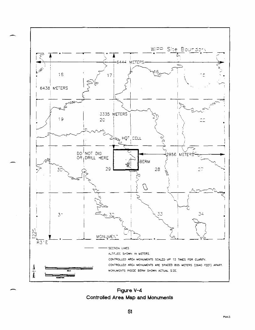
The controlled area monuments will be engraved with the Appendix 3 message also in seven languages. In addition the controlled area monuments will have inscribed the Figures IV-8 and V-4. Figure IV-8 will assist in establishing the date of the site as described above. Figure V-4 will provide an overall perspective of the location of the repository footprint to the controlled area perimeter defined by the controlled area monuments.
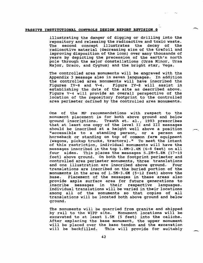
One of the MP recommendations with respect to the monument placement is for both above ground and below ground inscriptions. Trauth et. al., 1993 prescribes that at least one copy of the level I1 and I11 messages should be inscribed at a height well above a position -. "accessible to a standing person, or a person on horseback or standing on top of common farm equipment (wagons, pickup trucks, tractors)." To meet the intent of this restriction, individual monuments will have the messages inscribed in the top 1.8M-2.4M (6-8 feet) on all four sides. This places the messages 5.2M-5.8M (17-19 feet) above ground. On both the footprint perimeter and controlled area perimeter monuments, three translations and one illustration are inscribed above ground. Four translations are inscribed on the buried portion of the monuments in the area of 1.5M-3.6M (5-12 feet) above the base. Placement of the messages in these areas also provide ample surface area for future generations to inscribe messages in their respective languages. Individual translations will be varied in their locations among all of the monuments so that copies of all translations will be located both above ground and below ground.
The monuments will be quarried from granite and shipped by rail to the WIPP site. Monument locations will be excavated to at least 1.5M (5 feet) into the caliche. After emplacing the base monument, the upper monument will be placed over the base tendon and the excavation will be backfilled. This will provide for suitably -
PASSIVE INSTITUTIONAL CONTROLS DESIGN REPORT REVISION 0 . L
supporting the base monument within the caliche aepgsit or the Gatuna formation even under conditions in which the overlaying layer of sand is removed through erosion or other weathering phenomena. The calculated center of gravity of the two monolithic stones is 4.7M (15.5 feet) above the bottom of the base. The monolithic structure would require sufficient erosion to tip approximately 14.5 degrees from the vertical before the structure would become unstable.
In discussions with a number of quarry operators nation wide and a memorial distributor in the local area it is apparent that granite will come in a variety of grades. Granite is commonly referred to as blue, grey, black, or red. The color is a result of the granite composition and the hardness will vary. As a result of this condition, the testing addressed in Section IX below provides for subjecting a number of different types of granite to long term testing prior to actual purchase of the final monuments. A local memorial distributor with over 40 years of actual experience in the Carlsbad area stated that his experience with one of the harder grades, blue granite from Vermont, has not been as good with respect to durability of the engraved surface as with grey granite from quarries in Georgia. Although this is only a single reference point, it does support the proposed testing of various grades of granite over a period of decades prior to the final monument material decision.
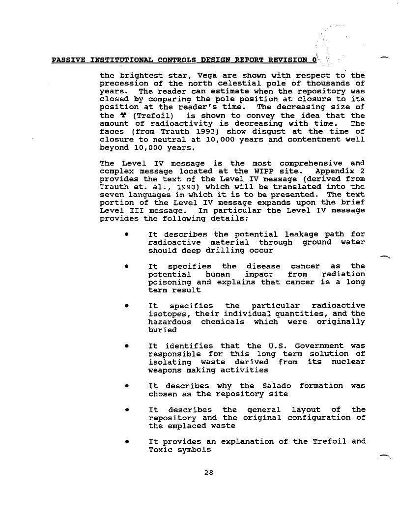
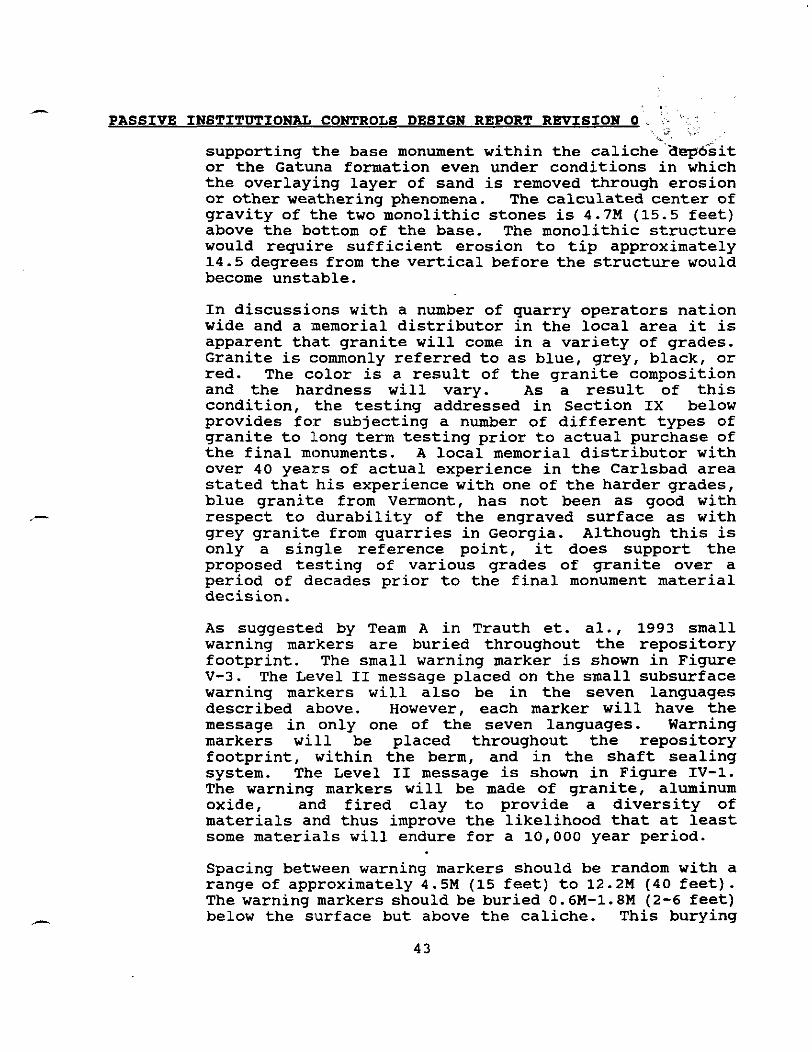
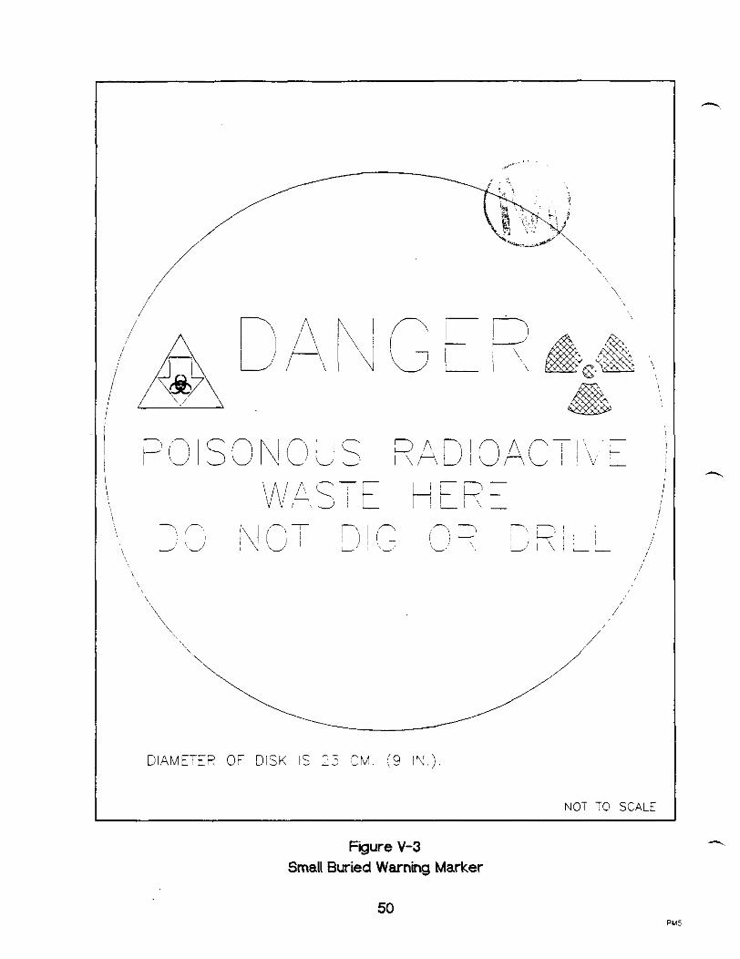
As suggested by Team A in Trauth et. al., 1993 small warning markers are buried throughout the repository footprint. The small warning marker is shown in Figure V-3. The Level I1 message placed on the small subsurface warning markers will also be in the seven languages described above. However, each marker will have the message in only one of the seven languages. Warning markers will be placed throughout the repository footprint, within the berm, and in the shaft sealing system. The Level I1 message is shown in Figure IV-1. The warning markers will be made of granite, aluminum oxide, and fired clay to provide a diversity of materials and thus improve the likelihood that at least some materials will endure for a 10,000 year period.
Spacing between warning markers should be random with a range of approximately 4.5M (15 feet) to 12.2M (40 feet) . The warning markers should be buried 0.6M-1.8M (2-6 feet) below the surface but above the caliche. This burying

. .. , i , . : .:: I.,
PASSIVE INSTITUTIONAL CONTROLS DESIGN REPORT REVISION 0 ,z ..* ? , $+, 'tc ;; ':',, -.
- 2
criterion is based upon two conditions. The'%& condition is that the soil covering the caliche in the local WIPP area ranges to a depth of 3M (10 feet). The second condition is based upon Ahlen, 1995. Ahlen, 1995 discusses local drilling operators' standard practice for drilling preparation. Typically a local well drilling service company will prepare an area 79M by 91.5M (260 feet by 300 feet) in preparation for drilling and an additional 46M by 46M (150 feet by 150 feet) area for a reserve pit (mud pit). The reserve pit will be excavated to a depth of 1.2M to 1.8M (4-6 feet) . A cellar excavated to 1.8M (6 feet) will be prepared to accommodate the drilling rig. Thus by placing the small warning markers in the range of 0.6M-1.8M (2-6 feet) below the surface at random intervals a large number of warning markers are available for discovery during the drill site preparation and excavation process. This provides a reasonable likelihood that at least some of the warning markers will be discovered by the drilling crew. Random spacing precludes souvenir hunters from identifying a burial pattern making excavation and retrieval of a large number of the small markers a less labor intensive effort. - Trauth et. al., 1993 discusses the use of deep markers. Discussions were held with local drilling company representatives regarding possible techniques for alerting drilling crews. A practicable scheme of marking the repository in such a manner as to call the attention of drill crews to the potential that radioactive waste is about to be entered by the drill bit was not identified. Ahlen, 1995 confirms the inability of alerting and stopping a drilling crew short of the supervisor directing them to stop. In discussing drilling routines and the degree to which the drilling fluid is monitored once the routine drilling operation has commenced, the oil field drilling company representatives stated that close observation of the fluid does not occur until the bit is below the local salt formations. Unless an extremely hard material (steel or titanium) was emplaced to encounter the drill bit and dull it quickly, the drilling operation would not likely be stopped based even upon encountering rock that is harder to drill than salt. According to at least one local drilling contractor, most drilling plans identify the depth to which the drilling operation is targeted and after some initial checks of the operation, continuous drilling proceeds to that depth with little or no significant monitoring of the drilling
h
PASSIVE INSTITUTIONAL CONTROLS DESIGN REPORT REVISION 0
fluid. One drilling company manager stated that if 2-3 inches of steel or titanium were encountered, it would probably impact the drilling operation sufficiently to cause additional investigation. Anything short of this would only be seen as an inconvenience. Again Ahlen, 1995 confirnts this information.
A second drilling operations supervisor stated that drilling fox oil and gas in the local area required depths of 8,000 and 16,000-feet respectively. Knowledge of the area was such that no examination of the drilling fluid is normally conducted until after the drill has passed through the salt layers. The same supervisor also stated that the drill cuttings ranged in size from about 3 micron grains to small slivers up to 3.8 cm (1 1/2 inches) in length. Under these conditions, there is no practical way to provide a message. In addition, current drill materials can typically penetrate even granitic rock at 1.8-2.4M (6-8 feet) per hour. It was the opinion of at least one drilling supervisor that for a 1.3 cm (1/2 inch) steel plate to dull a bit sufficiently to prevent penetration, the steel would require placement at a shallow depth otherwise the weight of the drill string would sufficiently improve the penetration capability of the drill bit to cause penetration of the steel plate without alerting the drill crew to any unusual condition. Placing steel plate near the surface would be counter to the requirement to not use material of intrinsic value. In addition, the corrosion resistance of steel reduces the likelihood of its remaining an effective barrier over the period of 10,000 years.
. Emplacement of markers in the panels immediately above the waste would be ineffective since there would be insufficient lead time to alert the crew even if the drilling crew was closely monitoring the drilling fluid content. The use of a dye was also discussed as a possible marking option. Discussions with a number of dye manufacturers and suppliers failed to locate a dye material which would affect the drilling fluid at concentrations that might be developed from dying materials einplaced with the waste. In addition, some means would be needed to provide a message cautioning the drilling crew as to why the dye was present. Finally, the use of pyrotechnics as deep marker components is not practical since significant quantities of drilling fluid under high pressure are used to flush out the drill cuttings. The fluid would extinguish any flammable materials long before the material could be brought to
PASSIVE INSTITUTIONAL CONTROLS DESIGN REPORT REVISION 0
the surface. to alert the drilling crew. If thermite were used in such a configuration and quantity as to melt the drill bit, it might stop the operation but without any message to convey to the drillers what they were about to enter, the drillers have one of three choices:
They could change out the drill bit and commence drilling again. In this case they would successfully pass through the waste unless the design included multiple layers of thermite separated sufficiently to prevent sympathetic detonation
They could abandon the drill site and setup elsewhere. In this case they might strike another thermite condition and abandon the attempt or simply move a third time
They could abandon the area altogether
Whatever material was used to "meltw the drill would have to be designed in a protective cover to remain stable for 10,000 years. In addition, a prodigious quantity of the material would be required and in itself would represent -. a significant hazard during fabrication and field emplacement.
Tolan, 1993 reports that experience with environmental remediation work on old landfills indicate that old tires or steel fencing/baling wire can make effective barriers to at least truck-mounted rotary drilling. He states that in two cases where the material was layered greater than 10 meters, the problems presented to the drillers resulted in their abandoning the boreholes.
The installation of a 10M (30 feet) thick barrier of old tires or steel wire represents a significant construction effort when considering a repository footprint excluding the area of the pillars between repository rooms and panels of 0.13 km2. Placing the barrier near the surface requires excavating the entire area to provide a reasonable expectation that the repository is protected. Emplacing the barrier only over the room footprints and not the pillars would ignore the risks associated with drilling near the pillar/room boundaries and the inaccuracies that might be associated with the vertical trueness of the drilling process. Emplacing the barrier nearer the location of the repository over the room
1

PASSIVE INSTITWl'IONAL CONTROLS DESIGN REPORT REVISION 0
footprints plus some small percentage overlap may require significant additional studying to determine what if any effects this additional mining above the repository may have on the performance of the repository. This additional study time could significantly affect obtainingthe required permits to begin waste emplacement and yet result in a barrier that will not be effective against slant or possible future horizontal drilling techniques.
When discussing what action a drilling crew might take upon encountering a barrier made of old rubber tires, the experienced drillingpersonnel interviewed respondedthat they would investigate the problem. Under current operating practices, this would entail a review of the maps provided by state and federal agencies to determine what might be the cause. However, unless some means not yet identified provided a message regarding the presence of the repository, drilling would probably recommence. In that a typical 8,000 feet deep oil well in the WIPP locale costs $300,000, abandoning a well after drilling over one thousand feet represents a significant financial loss.
As stated at the beginning of this Section, a practical means of warning the drilling crew that they are about to enter the waste repository has not been identified. Therefore this conceptual design report does not provide a recommendation for emplacing a deep marker system in the strata above the repository.


DIAGRAM INSCRIPTION NOlL 6
NOlE 3
"DIE 4
NOlE 5
NOT TO SCALE
Figure V-3 Small Buried Warning Marker
PUS
jf;i35 S j ~ e E3yrC;;r\ -- .- .- 7 T - ,
1 8 . - , - \ .
-. 'S 1
I --
-- i !
!
I C
BERM !
I
2 9 28
! I
I i !
34
i
231 E - .- SECTION LINES
ALTITUDE SUOWN IN METERS.
CONTROLLED AREA MONUMENTS SCALED UP 72 TIMES FOR CLARITI.
CONTROLLED A R M MONUMENTS ARE SPACED 8 0 5 METERS ( 2 6 4 0 FEET) APART.
.- mu% MONUMENTS INSIDE BERM SHOWN ACTUAL SIZE
Ftgure V-4 Controlled Area Map and Monuments

A
PASSIVE INSTITUTIONAL CONTROLS DESIGN REPORT REVISION 0
VI . STORAGE ROOM
The planned buried Storage Rooms differ from those recommended by Trauth et. al., 1993 in that they will be constructed of granite. Granite is the chosen material for the same reasons provided earlier. In addition, the complexity and length of the Level IV message and its supporting diagrams significantly impact the ability to "engraven the messages in concrete. What would be required is that the concrete forms themselves contain the detail. This would probably require some significant development effort. Conversations with granite quarries which do provide engraving (e.g. Rock of Ages, Bear VT) indicate that the small aggregate in concrete precludes engraving, especially small letters. No quarry operators contacted were aware of organizations experienced in providing lengthy complex messages in concrete. Use of Chinese characters would further complicate the development of forms to conduct such an operation.
The storage room for containing the Level IV message and associated diagrams is designed to endure for the 10,000 year period of the regulatory concern. The design characteristics contributing to this longevity are the -. material and environmental conditions associated with its construction and location. The room is made of granite with a minimum number of joints. In addition no mortar is required. This consideration is a result of Trauth et. al., 1993 suggestion that dissimilar materials be avoided since the chemical interaction over centuries may be adverse to the structures integrity. As designed, individual walls, the floor, and the roof are comprised of single granite slabs joined only at the perimeter locations. The internal walls are each made of three sections to provide redundancy of the information as suggested in Trauth et. al., 1993. Figure VI-1 is an isometric view of the planned buried storage room containing the Level IV message. The magnets shown in the figure are to provide a magnetic signature to permit locating the room buried within the controlled area outside the repository footprint. Figures VI-2 through VI-4 show views of the building from the top, the side, and the end. They include overall dimensional characteristics. The configuration minimizes the risk of failure due to chemical interactions between the construction material, the joining materials, and the environment.
i i... ., ' ~ : ,. . r. .,.",' - PASSIVE INSTITUTIONAL CONTROLS DESIGN REPORT REVISION
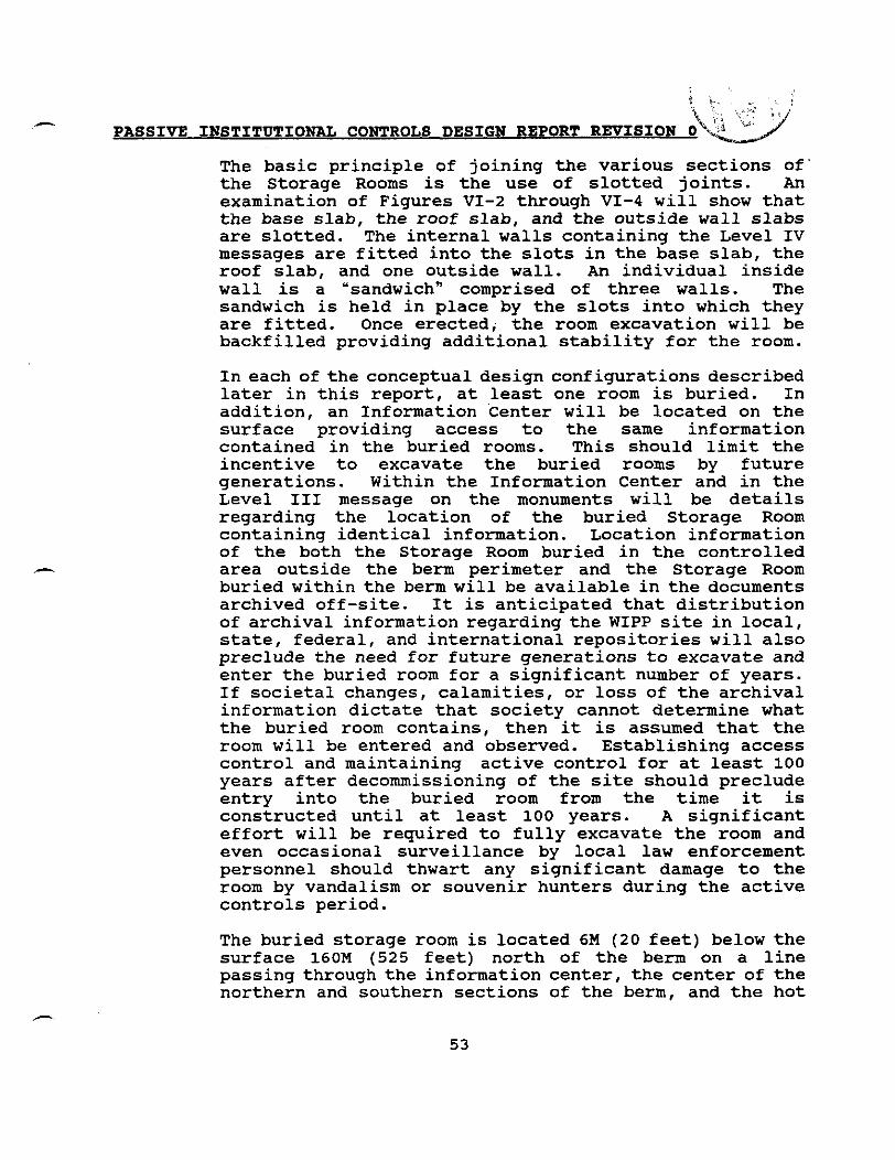
The basic principle of joining the various sections of' the Storage Rooms is the use of slotted joints. An examination of Figures VI-2 through VI-4 will show that the base slab, the roof slab, and the outside wall slabs are slotted. The internal walls containing the Level IV messages are fitted into the slots in the base slab, the roof slab, and one outside wall. An individual inside wall is a 'sandwichn comprised of three walls. The sandwich is held in place by the slots into which they are fitted. Once erected, the room excavation will be backfilled providing additional stability for the room.
In each of the conceptual design configurations described later in this report, at least one room is buried. In addition, an Information center will be located on the surface providing access to the same information contained in the buried rooms. This should limit the incentive to excavate the buried rooms by future generations. Within the Information Center and in the Level I11 message on the monuments will be details regarding the location of the buried Storage Room containing identical information. Location information of the both the Storage Room buried in the controlled area outside the berm perimeter and the Storage Room buried within the berm will be available in the documents archived off-site. It is anticipated that distribution of archival information regarding the WIPP site in local, state, federal, and international repositories will also preclude the need for future generations to excavate and enter the buried room for a significant number of years. If societal changes, calamities, or loss of the archival information dictate that society cannot determine what the buried room contains, then it is assumed that the room will be entered and observed. Establishing access control and maintaining active control for at least 100 years after decommissioning of the site should preclude entry into the buried room from the time it is constructed until at least 100 years. A significant effort will be required to fully excavate the room and even occasional surveillance by local law enforcement personnel should thwart any significant damage to the room by vandalism or souvenir hunters during the active controls period.
The buried storage room is located 6M (20 feet) below the surface 160M (525 feet) north of the berm on a line passing through the information center, the center of the northern and southern sections of the berm, and the hot

PASSIVE INSTITUTIONAL CONTROLS DESIGN REPORT REVISION 0 -
P .
cell concrete artifact standing approximately 320Ef1&%050 w
feet) north of the berm centerline. The overall room dimensions are approximately 11.9M long by 6.7M wide by 4.9M high (39 feet by 22 feet by 16 feet). The message texts in Appendix 2 are engraved on the walls in the arrangement similar to that for the Information Center shown in Figure VII-1. In addition the diagrams are arranged on the walls of the rooms similar to that shown in Figure VII-1 for the Information Center and as depicted in Figure VI-4 for the buried rooms. To provide redundancy, additional granite slabs engraved with the message text and the diagrams are held in place against the interior walls. The room entrance is a single plug in one wall measuring 0.6M (2 feet) at the inner minimum diameter. The tapered plug weighs approximately 1600 pounds. Its removal will require more than a single individual in all likelihood. The opening is small so that the room contents cannot be removed easily by an unorganized group or individuals intent on vandalism. Although some damage could be inflicted by vandals, the granite composition of the message carrying materials provides the greatest opportunity for preventing complete destruction of the information contained within the - buried room.
A second storage room will be buried within the berm. It will be located at the center of the southern berm section. The room will be erected at grade level and the berm will be built over it. The presence of this room will not be identified in any of the messages available at the site. However, its presence will be described in the archived information. The purpose of this room is to provide a source of information that would become available in the unlikely event that circumstances cause erosion or dismantling of the berm far into the future.
The physical size of the Storage Rooms is dictated by the minimum size lettering which can be engraved in granite. Discussions with a number of quarry operators and local memorial vendors indicate that the minimum lettering size is 5/811. This is limited by the sandblasting technique typically used. Engraving smaller size letters causes "blowout" of small enclosed character such as "A", "P", "R" , etc. No laser engraving capability exists within the granite quarrying industry. Additional discussions with laser manufacturers verified the lack of laser engraving capability on large pieces of granite. One
h
-. PASSIVE INSTITUTIONAL CONTROLS DESIGN REPORT REVISION 0
manufacturer stated that he gets called at least once a week by memorial dealers inquiring about laser engraving technology. Two reasons are given for the lack of the technology today. First, high laser power (6-8 kilowatts) would most likely be required. Second, the granite quarry and memorial industry is not willing to spend the research money required to develop the technology. This particular manufacturer suggested perhaps that a national lab attempting to convert defense related technology to commercial use might take on such a development effort. In any event, the technology does not exist today to engrave granite with characters smaller than 5/8".

Figure VI-1 Storage Room
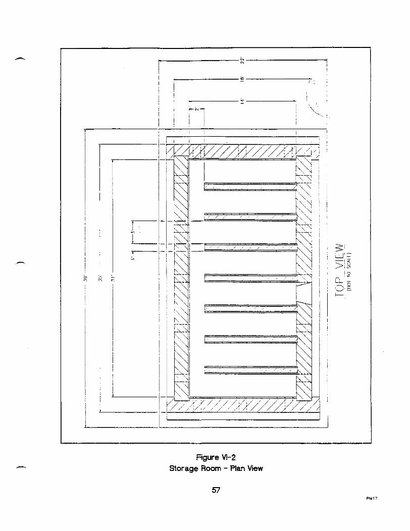
f i - e I
Figure Vl-2 Storage Room - Plan View
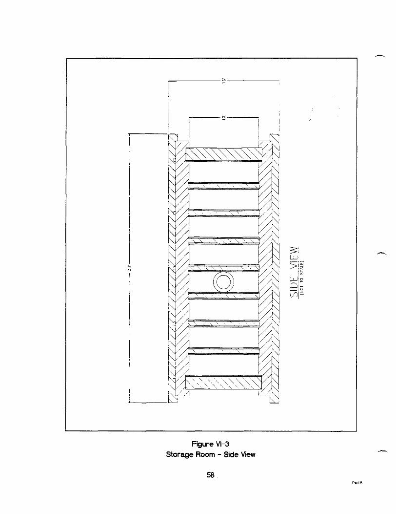
Figure VI-3 Storage Room - Side V I W

Figure VI-4 Storage Room - End View

i
PASSIVE INSTITDTIONAL CONTROLS DESIGN REPORT REVISION 0 l. - -,
VII. INFORMATION CENTER 4,
An isometric drawing of the Information Center shown in Figure VII-1 illustrates an above ground structure which contains the same information provided in the buried storage rooms. Contrary to the recommendation for a closed room found in Trauth et. al. , 1993 the Information Center is an open structure. Allowing the structure to be open permits natural light to illuminate the Level IV message and supporting - diagrams and tables for observation without the need for powered artificial light.
Construction of the Information Center is comprised of solid granite walls embedded 1.5M (5 feet) into compacted caliche for support. Engraved on the walls is the Level IV message in seven languages and the graphics information provided in the storage rooms buried underground. Figure VII-2 provides the dimensional characteristics of the Information Center exterior and interior walls. Placement of the walls and the relatively narrow spacing between the walls will minimize the erosion due to wind driven sand and rain. Upon completion of construction, the area surrounding the - Information Center will be graded to provide for runoff of rainwater from the structure itself.
In addition to the Level IV message and its associated diagrams, the Information Center will also contain a message regarding the location of the controlled area buried Storage Room. The message provides information for locating the room both in relation to the Information Centerlberm and by magnetic signature. The magnetic signature is developed by permanent magnets similar to those described in Section VIII below. The message cautions not to excavate the Storage Room arbitrarily but to leave it alone for future generations as a backup in the event that the information presented on the Information Center walls has been lost. It also requests that the room be re-buried if conditions have caused it to become exposed.
It is anticipated that this structure and its information will endure as long as the monuments. However, should history find this not to be the case, the information will also be available in the controlled area buried Storage Room and the Storage Room in the berm .

C PASSIVE INSTITUTIONAL CONTROLS DESIGN REPORT REVISION 0
Figure VII-3 provides a plan view of the repository footprint showing the relative locations of the permanent marker components associated with the footprint.

Figure VII-1 Information Center

Figure Vll-2 Information Center Fabrication Details

S INFORMATION CENTER
. MONUMENT
STAIRS I
!."#LJ. , 1. THE GRANITE MONUMENTS ARE PLACED APPROXIMATELY 1 5 0 METERS ( 5 0 0 FEET!
APART ON THE NORTHERN AND SOUTHERN SIDES OF THE REPOSITORY FOOTPRINT : AND APPROXIMATEL" 2 1 0 METERS ( 7 0 0 FEET) APART ON THE EASTERN AND "7 rn WESTERN SIDES OF THE REPOSITORY FOOTPRINT. _I
a,
2 EACH MONUMENT IS FOUR F E T SOUARE ANC STANDS TWENn-FIVE FEET ABOVE THE SURFACL
3 THE INFORMATION CENTER WHICH COVERS AN AREA OF F O R M FEET BY THIRTY lWO FEET. IS LOCATED IN THE CENTER OF THE REPOSITORY
4 . A BURIED ROOM IS LOCATED 160 METERS NORTH OF THE NORTHERN BERM ON A LlNE PASSING THROUGH THE INFORMATION CENTER AND THE HOT CELL CONCRETE ARTIFACT STANDING APPROXIMATELY 320 METERS NORTH OF THE BERM CENTER LINE.
--
Fgure Vll-3 Repository Footprint Permanent Marker Plan View

h PASSIVE INSTITUTIONAL CONTROLS DESIGN REPORT REVISION 0:
Z VIII. BERM CONFIGURATION
The premise to base a permanent marker design on the construction of a berm or berm like structure is based upon the following arguments:
The structure should identify the extent of the surface footprint of the repository but need not follow the footprint outline
0 The structure should be sufficiently massive to provide a reasonable expectation that it will endure for 10,000 years
The structure's profile should minimize the likelihood that it can become buried by shifting sands or that characteristics of the profile may lead to fabrication stresses affecting the ability of the structure to retain its configuration
1 t should be constructible without the need for high tech equipment or processes
Its construction materials should be reasonably available to the WIPP site and have as little intrinsic value as is reasonable
0 To the extent practicable the nature of the structure should lend itself to valid testing over a period of 2-5 decades
Trauth et. al., 1993 explores a number of different techniques and structures for defining the repository's surface footprint. Characteristics unique to the individual structures identified and the resulting recommendation from each of the two teams is to use a berm like configuration. A berm also meets the arguments listed above to a greater extent than any of the other configurations proposed. Team A's recommended berm configuration is one of a "menacing earthworksn. Team B described an earthworks in the form of a trefoil. In that the berm represents the largest structure of the permanent marker conceptual design, both team's configurations are discussed in following sections of this report in conjunction with the selected berm configuration. The selected berm configuration represents a number of advantages over those suggested in Trauth et. al., 1993. First, the selected berm
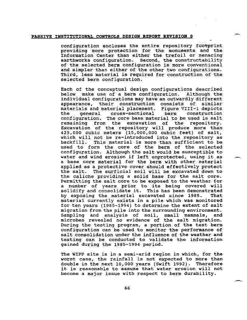
PASSIVE INSTITUTIONAL CONTROLS DESIGN REPORT REVISION 0 , .
configuration encloses the entire repository fo-0-rint providing more protection for the monuments and the Information Center than either the trefoil or menacing earthworks configuration. Second, the constructability of the selected berm configuration is more conventional and simpler than either of the other two configurations. Third, less material is required for construction of the selected berm configuration.
Each of the conceptual design configurations described below make use of a berm configuration. Although the individual configurations may have an outwardly different appearance, their construction consists of similar materials and material placement. Figure VIII-1 depicts the general cross-sectional berm construction configuration. The core base material to be used is salt remaining from the excavation of the repository. Excavation of the repository will produce more than 425,000 cubic meters (15,000,000 cubic feet) of salt, which will not be re-introduced into the repository as backfill. This material is more than sufficient to be used to form the core of the berm of the selected configuration. Althoughthe salt would be susceptible to water and wind erosion if left unprotected, using it as -. a base core material for the berm with other material applied as a protective cover should effectively protect the salt. The surficial soil will be excavated down to the caliche providing a solid base for the salt core. Permitting the salt core to be exposed to the weather for a number of years prior to its being covered will solidify and consolidate it. This has been demonstrated by exposing the material excavated since 1985. That material currently exists in a pile which was monitored for ten years (1985-1994) to determine the extent of salt migration from the pile into the surrounding environment. Sampling and analysis of soil, small mammals, and microbes revealed no evidence of the salt migration. During the testing program, a portion of the test berm configuration can be used to monitor the performance of salt consolidation under the influence of the weather and testing can be conducted to validate the information gained during the 1985-1994 period.
The WIPP site is in a semi-arid region in which, for the worst case, the rainfall is not expected to more than double in the next 10,000 years (Swift 1992). Therefore it is reasonable to assume that water erosion will not become a major issue with respect to berm durability.

+ r
? .
PASSIVE INSTITUTION?& CONTROLS DESIGN REPORT REV1SIOk@ . -- 11
A practical and locally available protective covering for the salt core is the caliche soil found locally up to 15 feet below the surface. Large quantities are available. The caliche is reasonably impervious to water penetration in the semi-arid environment of the WIPP. Studies of the locale report that even at the height of an ice age, the annual rainfall is not expected to more than double its Current 13 inches per year average. Therefore 2-3 meters of caliche compacted over the salt core should provide significant protection of the salt from water. This was confirmed with Mr. Edward Rector of the New Mexico Highway Department's Materials and Research Laboratory. Mr. Rector stated that the caliche should be graded so that 30%-40% of a sample would pass through a number 200 sieve to achieve a relatively impermeable barrier. As with the consolidation of the salt, the validity of the assumption of compacted caliche's ability to protect the salt from water intrusion can be tested during the testing program.
A third layer of berm material will be comprised of riprap quarried near Carlsbad, NM. This will provide protection for the caliche from wind erosion. It will also provide for runoff of rainwater to the surrounding desert with minimum water erosion of the caliche layer. The final layer of berm material will consist of a mixture of riprap and native soil. This should support local vegetation and add another erosion resistant characteristic to the overall berm configuration. During the disposal phase of the WIPP, testing will be conducted to determine what combination of rock sizes, soil, and vegetation provide the best likelihood of success, at least in the near term (100 years).
In that the berm configuration totally encloses the repository footprint, see Figure VIII-2, some means needs to be provided to mitigate the possibility of significant ponding occurring during heavy rainfall. To provide for drainage to outside the berm enclosed area, drainage paths through the berm will be provided at approximately lOOM (328 feet) intervals. These drainage paths will consist of riprap filled trenches 3M (10 feet) deep and 2M (6.5 feet) wide through the berm base below the surf ace.
To provide a unique magnetic signature for the berm with respect to the local geology as recommended by Team A in Trauth et. al., 1993, an investigation into the use of

%.
PASSIVE INSTITUTIONAL CONTROLS DESIGN REPORT REVISION b
magnetite as a layered material over thekvsalt was conducted. Although magnetite in its natural state often demonstrates a detectable magnetic anomaly, large quantities removed by mining and transported to another locale for the purpose of providing a local detectable magnetic anomaly may not provide the same level of magnetic anomaly as the material in its natural state. In its natural state, the mineral magnetite (Fe,O,) develops its magnetic signal through induced magnetism from the earth's own magnetic field over eons of time. When mined, the magnetite material becomes mixed up and the individual dipoles will not all be aligned to reinforce each other as is found in the natural state (Mallick, 1994). Large quantities of the mineral after being emplaced could be magnetized with a large electromagnet. However, the practicality of successfully completing such a task would require considerable effort to demonstrate and evaluate. Even if successful, the retention of the artificially induced magnetic field over thousands of years is unknown and could not be determined with a high degree of certainty (Mallick, 1994). In view of the shortcomings of magnetite, a unique magnetic signature will be provided by large permanent magnets. -~ To provide a distinctive magnetic signature for the berm, large permanent magnets buried in the berm can be used, Mallick 1994 and Krefta 1994. Large strontium ferrite permanent magnets buried within the berm at intervals of 75-100 meters would give a signal detectable with current state of the art airborne equipment 100 meters above the magnets. The individual magnets would be approximately 1 meter in length and 1/2 meter by 1/2 meter in cross- section. Should future climatic conditions cause sand shifts so extensive that the berm and monuments become covered (not expected), future generations conducting magnetic surveys of the area should still be able to detect a magnetic anomaly resulting from the permanent magnets. The magnetic signal's geometric form will provide strong indication that it could only have been man made. This should inspire any organization capable of magnetic surveying to investigate this anomaly further prior to initiating any planned drilling activities in the local area enclosed by the magnetic signature.
Team B (Trauth et. al., 1993) suggested the use of high dielectric materials be used to provide a unique radar signature for the site. Bellus 1994 provides a description of the use of trihedrals fabricated from
A
metal as a means of providing a radar reflective signature unique from the surrounding terrain. Figure VIII-3 illustrates the basic trihedral configuration. Current ground penetrating radars operate below 100MHz. Much of the communication allocations occupy frequencies below lOOMHz, therefore, radars operating below this range must use filters to avoid problems with communications bands. Bellus reports that recent experience in the middle east with SeaSat operating at 1.2GHz produced excellent images of roads and structures buried under the desert.
The dimensional characteristics of a trihedral facet that will give a peak Radar Cross Section (RCS) is 3X the wave length of the incident radar signal. Assuming a radar operating at 1 GHz, a trihedral with facets measuring 0.9 meters on a side will be optimal. This will provide a peak RCS of 17dBsm/sm (decibels square meter per square meter), Bellus 1994. The typical peak terrain RCS is - 15dBsm/sm. The difference in RCS strength operating at 1 GHz is 32 dBsm/sm. This will give a highly visible signal. Thetrihedrals will be fabricated from stainless steel or inconel and placed within the berm at the surface of the salt core. To provide a unique radar signature, the trihedrals will be grouped in sets of four spaced approximately every 91M (300 feet) around in the berm as shown in Figure VIII-2. In addition, four trihedrals will be placed around controlled area buried room to provide a unique radar signature at the room location. One trihedral will be placed adjacent to each room exterior wall approximately midway along the wall. During the testing period conducted throughout the disposal phase and for some period after decommissioning, buried bare stainless steel trihedrals, trihedrals encased in concrete, and inconel trihedrals should be evaluated for performance of their respective RCS and corrosion resistance. Encasing the trihedral in concrete reduces the likelihood of its being efficiently salvaged and also may add to the effective lifetime of the trihedral by the protective concrete covering.
A final feature of the berm structure is the burying of a Storage Room within the berm. Section VI above describes the Storage Room design and content. The berm Storage Room will be buried midway in the southern portion of the berm opposite the Information Center. Location is arbitrary since there is no obvious natural phenomenon which would erode any one portion of the berm more rapidly than another. Unlike the room buried in the
PASSIVE I N S T I T U T I O N U CONTROLS DESIGN REPORT REVISION 0
controlled area north of the berm, it is DOE'S intent to not describe the berm room's location within the messages at the site. The location will be described in the archived material. The intent of this action is to minimize the likelihood of the room being excavated by local individuals. The primary reason for burying the room within the berm is to provide a source of information in the unlikely event that all the other monuments associated with the site are removed. Under these conditions, dismantling of the berm by future generations would uncover an information source that might again establish why the WIPP site exists and why intrusion of its repository should be avoided.

B E X M CROSS SECTION BERM CONSTRUCTION PROFILE
NOT TO SCALE
Figure WII-1 Berm Configuration

-.. SET 3F 4 TRIHE3RALS
Figure Vlll-2 General Trihedral Arrangement

Fgure Wll-3 Trihedral Configuration

PASSIVE INSTITUTIONAL CONTROLS DESIGN REPORT REVISION 0 -.
IX. TESTING i . \* - 1"
Upon closure of the WIPP, at the conclusio>dthe Disposal Phase, active controls will be implemented to control the access to the site and long term monitoring systems will be managed to detect significant deviations in repository performance. With active control provided over the site, the schedule for construction of the permanent marker system is dependent upon the results of the testing described below. However, It is DOE intent to complete implementation of PIC including the construction of the permanent marker system by the end of 100 years after closure of the site. In that the design of the permanent marker system has a long lifetime goal, it is prudent that the DOE conduct some long range testing of the construction materials planned for use as permanent marker material.
One aspect of the long term testing is the construction of a section of the berm. The overall size (height and width) of the test section of the berm will match the design of the permanent marker berm. However, the test berm length will be shorter than the full size berm. A section approximately 50 to 100 meters will provide a -. length sufficient to test a number of different configurations. Included within the test section will be varying thicknesses of the salt core, the caliche layer, and the top layer of riprap and soil material. The DOE will construct a section of the berm for the purpose of evaluating materials and constructiontechniques. Actual construction and testing will initiate during the Disposal Phase to provide a maximal time for testing. During the disposal phase, the DOE may also emplace salt from the construction of the repository panels directly into the berm base and thereby permit the material to consolidate under the influence of the weather. This action would also reduce the amount of material that needs to be moved once the construction of the entire berm is started. The salt thus emplaced would remain uncovered for a significant number of years to consolidate prior to final construction of the berm.
The major subjects which may be evaluated during this testing program are:
Salt consolidation under the influence of the weather and/or implementation of artificial consolidation activity
-%
7 4
e PASSIVE INSTITUTIONAL CONTROLS DESIGN REPORT REVIBION 0 I
d i _ *
0 The system for unloading and moving large quantities of material from the railroad spur to the permanent marker site
a Performance of the railroad spur and maintenance required. This may impact a decision of whether to conduct periodic maintenance of the spur or refurbish it at the time of initiating construction of the permanent marker system
a Survey representative monuments within a 150 mile radius of the WIPP to more extensively evaluate the climatic environmental affects on granite
0 Identification of a suitable local source of caliche and establishing the required contractual and regulatory agreements to obtain and move the caliche in the quantities required
a Identification of a suitable local source of riprap and establishing the required contractual and regulatory agreements to obtain and move the riprap in the quantities required
Construction techniques applicable to a large berm. Determine what, if any, configuration changes may have significant impacts on the cost of construction
a Evaluate various berm surface materials (e.g., size of rocks, types of soil, types of vegetation) for durability and success in supporting vegetation overgrowth
a Procure, ship, and erect various type granites for the monument rock and evaluate long term environmental effects (e.g., wind, rain, and blowing sand). This will provide experience to be applied for contractual specifications developed for procurement and erection of multiple monuments. In addition concrete should be emplaced underground and tested for durability as a substitute for the granite in construction of some parts of the Storage Rooms proposed above (e.g., the floor and roofing slabs which will not be engraved)
Evaluate the magnetic signature, durability, and stability of sample permanent magnets (e.g., strontium ferrite, samarium cobalt, and alnico)
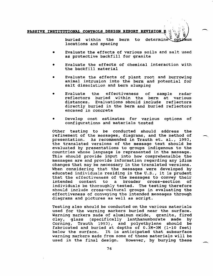
%I.
PASSIVE INSTITUTIONAL CONTROLS DESIGN REPORT -,
buried within the berm to um locations and spacing
Evaluate the effects of various soils and salt used as protective backfill for granite
a Evaluate the effects of chemical interaction with the backfill material
a Evaluate the effects of plant root and burrowing animal intrusion into the berm and potential for salt dissolution and berm slumping
a Evaluate the effectiveness of sample radar reflectors buried within the berm at various distances. Evaluations should include reflectors directly buried in the berm and buried reflectors encased in concrete
a Develop cost estimates for various options of configurations and materials tested
Other testing to be conducted should address the refinement of the messages, diagrams, and the method of -<
presentation. As recommended in Trauth et. al., 1993, the translated versions of the message text should be evaluated by presentations to groups indigenous to the countries whose language is represented in the message. This should provide input into how comprehensible the messages are and provide information regarding any idiom changes that may be necessary in the translated versions. When considering that the messages were developed by educated individuals residing in the U.S., it is prudent that the effectiveness of the messages to convey their intended content to a broader cross-section of individuals be thoroughly tested. The testing therefore should include cross-cultural groups in evaluating the effectiveness of conveying the intended messages through diagrams and pictures as well as script.
Testing also should be conducted on the various materials used for the warning markers buried near the surface. Warning markers made of aluminum oxide, granite, fired clay, glass (specifically lanthanumborate made by Corning, Trauth 1993), and polyethylene should be fabricated and buried at depths of 0.3M-3M (1-10 feet) below the surface. It is anticipated that subsurface warning markers made from some of these materials will be used in the final design. However, by burying these
6.
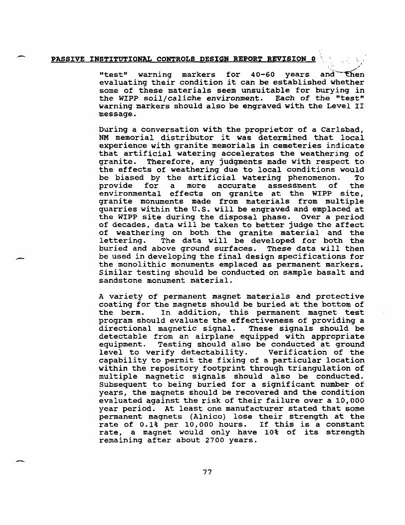
- PASSIVE INSTITUTIONAL CONTROLS DESIGN REPORT REVISION 0 '
"testw warning markers for 40-60 years andk-dn evaluating their condition it can be established whether some of these materials seem unsuitable for burying in the WIPP soil/caliche environment. Each of the "test" warning markers should also be engraved with the Level I1 message.
During a conversation with the proprietor of a Carlsbad, NM memorial distributor it was determined that local experience with granite memorials in cemeteries indicate that artificial watering accelerates the weathering of granite. Therefore, any judgments made with respect to the effects of weathering due to local conditions would be biased by the artificial watering phenomenon. To provide for a more accurate assessment of the environmental effects on granite at the WIPP site, granite monuments made from materials from multiple quarries within the U.S. will be engraved and emplaced at the WIPP site during the disposal phase. Over a period of decades, data will be taken to better judge the affect of weathering on both the granite material and the lettering. The data will be developed for both the buried and above ground surfaces. These data will then be used in developing the final design specifications for the monolithic monuments emplaced as permanent markers. Similar testing should be conducted on sample basalt and sandstone monument material.
A variety of permanent magnet materials and protective coating for the magnets should be buried at the bottom of the berm. In addition, this permanent magnet test program should evaluate the effectiveness of providing a directional magnetic signal. These signals should be detectable from an airplane equipped with appropriate equipment. Testing should also be conducted at ground level to verify detectability. Verification of the capability to permit the fixing of a particular location within the repository footprint through triangulation of multiple magnetic signals should also be conducted. Subsequent to being buried for a significant number of years, the magnets should be recovered and the condition evaluated against the risk of their failure over a 10,000 year period. At least one manufacturer stated that some permanent magnets (Alnico) lose their strength at the rate of 0.1% per lo, 000 hours. If this is a constant rate, a magnet would only have 10% of its strength remaining after about 2700 years.
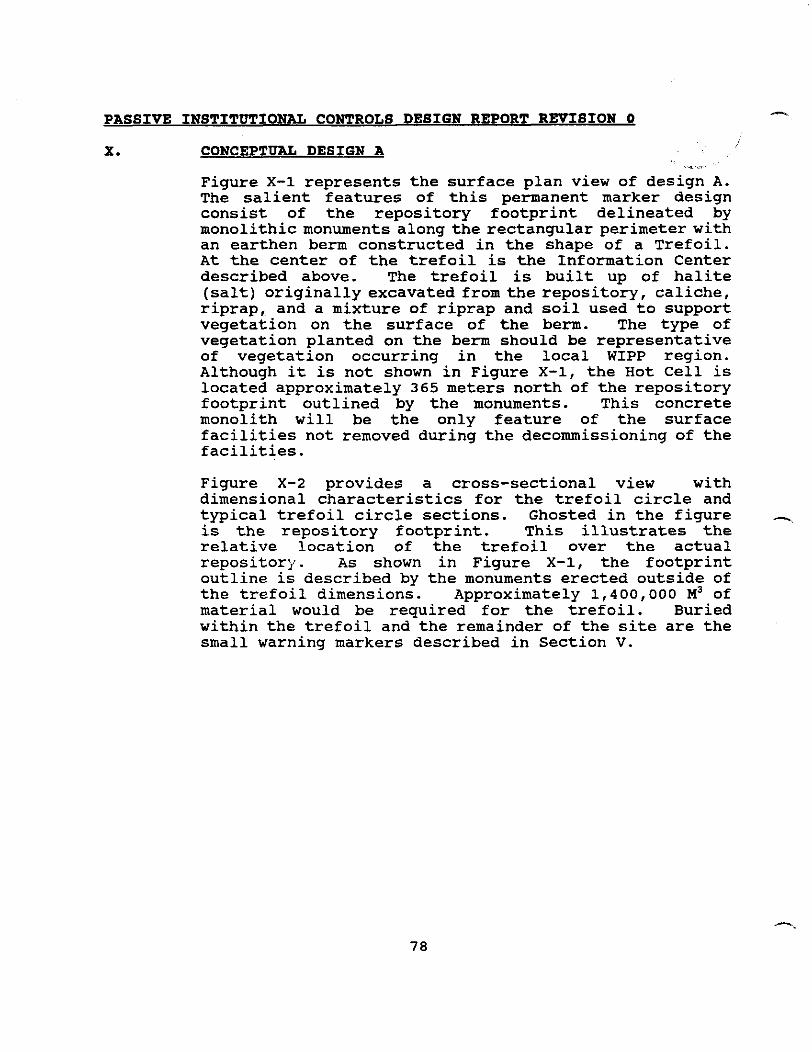
PASSIVE INSTITUTIONAL CONTROLS DESIGN REPORT REPISION 0 -
X. CONCEPTUAL DESIGN A
Figure X-1 represents the surface plan view of design A. The salient features of this permanent marker design consist of the repository footprint delineated by monolithic monuments along the rectangular perimeter with an earthen berm constructed in the shape of a Trefoil. At the center of the trefoil is the Information Center described above. The trefoil is built up of halite (salt) originally excavated from the repository, caliche, riprap, and a mixture of riprap and soil used to support vegetation on the surface of the berm. The type of vegetation planted on the berm should be representative of vegetation occurring in the local WIPP region. Although it is not shown in Figure X-1, the Hot Cell is located approximately 365 meters north of the repository footprint outlined by the monuments. This concrete monolith will be the only feature of the surface facilities not removed during the decommissioning of the facilities.
Figure X-2 provides a cross-sectional view with dimensional characteristics for the trefoil circle and typical trefoil circle sections. Ghosted in the figure - is the repository footprint. This illustrates the relative location of the trefoil over the actual repository. As shown in Figure X-1, the footprint outline is described by the monuments erected outside of the trefoil dimensions. Approximately 1,400,000 M~ of material would be required for the trefoil. Buried within the trefoil and the remainder of the site are the small warning markers described in Section V.
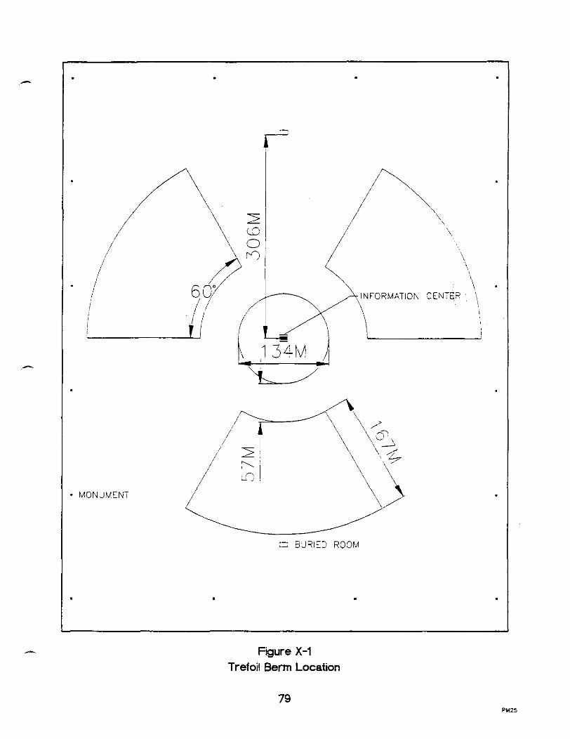
Fgure X-1 Trefoil Berm Location
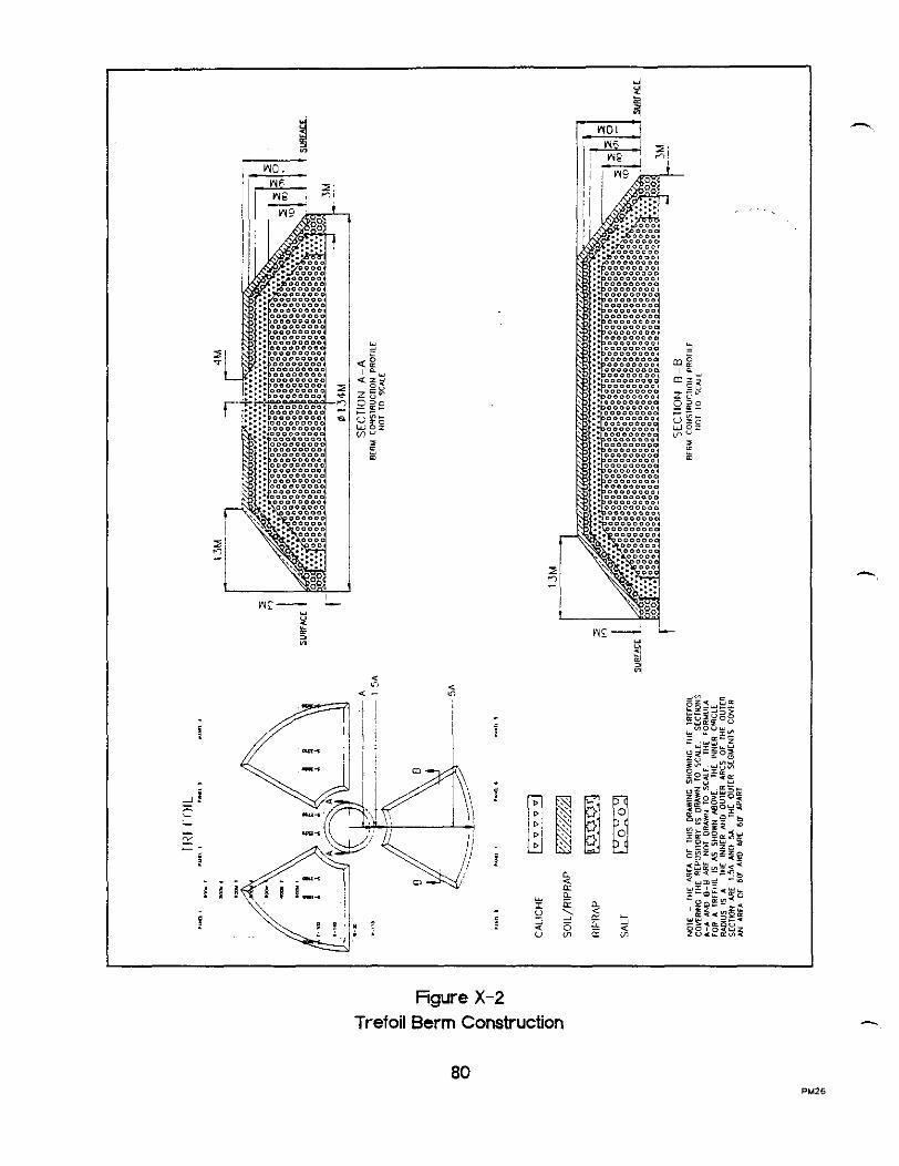
0 < (L-
u a I a n g 2 s 5 4 - o m a s
figure X-2 Trefoil Berm Construction
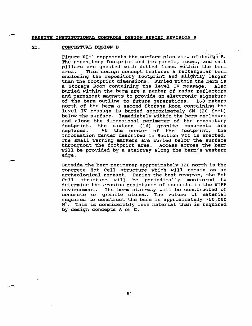
- PASSIVE INSTITUTIONAL CONTROLS DESIGN REPORT REVISION 0
XI. CONCEPTUAL DESIGN B
Figure XI-1 represents the surface plan view of desi* B. The repository footprint and its panels, rooms, and salt pillars are ghosted with dotted lines within the berm area. This design concept features a rectangular berm enclosing the repository footprint and slightly larger than the footprint dimensions. Buried within the berm is a Storage Room containing the level IV message. Also buried within the berm are a number of radar reflectors and permanent magnets to provide an electronic signature of the berm outline to future generations. 160 meters north of the berm a second Storage Room contaming the level IV message is buried approximately 6M (20 feet) below the surface. Immediately within the berm enclosure and along the dimensional perimeter of the repository footprint, the sixteen (16) granite monuments are emplaced. At the center of the footprint, the Information Center described in Section VII is erected. The small warning markers are buried below the surface throughout the footprint area. Access across the berm will be provided by a stairway along the berm's western edge.
Outside the berm perimeter approximately 320 north is the concrete Hot Cell structure which will remain as an archeological remnant. During the test program, the Hot Cell structure will be periodically monitored to determine the erosion resistance of concrete in the WIPP environment. The berm stairway will be constructed of concrete or granite stones. The volume of material required to construct the berm is approximately 750,000 M ~ . This is considerably less material than is required by design concepts A or C.
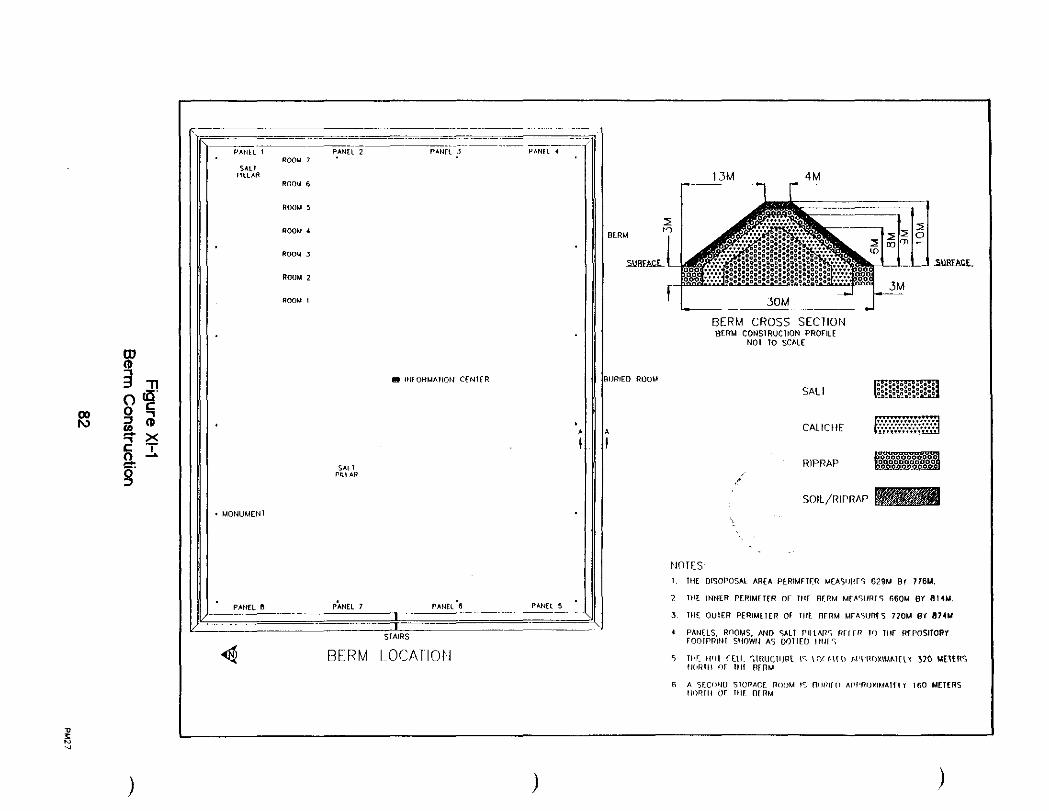
BERM CROSS SECTION BERM CONSIRUCIION P R o r l l t
NO1 TO SCALE
SALT
NOTES: I. I l i E DISOPOSAL AREA PERlMrlER MEASllRrC 679M 81 776M.
7 THE INNER PFRlMErER O r l l l E BERM MrA5l lRrS 660M BY 8 I4M.
3 l l l E OUIER PERIUI I IR Or 1111 OFRM UrhFIJRfS 72OM 61 874M
I PANELS. R ~ O M S . IWD y ~ r PIILNIC, w r r n I,) IN R~POSI~ORI r o n r P m t i l SIIOWII AS OOIIEU IIII~Y
5 mr. IIW CCIK :IRUCIIJBI IK ~ o ' n l t n WI'ROXIUAIIII 370 YETIRS I I~I I I or 1111 B ~ B M

h
PASSIVE INSTITUTIONAL CONTROLS DESIGN REPORT REVISION 0 \ i '~. .. ' 9, .:i :
XII. CONCEPTUAL DESIGN C ,,. ~ + '
Figure XII-1 represents the surface plan view of design C. This design concept incorporates the "Menacing Earthworks" concept recommended in Trauth 1993. Sections of earthen berms radiate outward from the perimeter of the repository footprint. The repository footprint outline is described by the emplacement of sixteen (16) granite monuments as utilized in designs A and B above. At each corner of the earthworks, a large earthwork structure is located. A Storage Room is buried within each of the four corner earthworks. Each Storage Room configuration is as described in Section VI. The Information Center is located at the center of the footprint and the small warning markers are buried within the footprint. Although it is not shown of Figure XII-1, the Hot Cell is located approximately 365 meters north of the repository footprint outlined by the monuments. This concrete monolith will be the only feature of the surface facilities not removed during the decommissioning of the facilities.
Figures XII-2 through XII-5 provide the profile structural details of the various earthwork configurations used to make up the "Menacing EarthworksN including the approximate total volume of material for each configuration. The various configurations and their mirror images are used in making up the total earthworks structure. The cross sectional material composition of the structure is similar to that shown in Figure XI-1. The total volume of material required to construct the berms is approximately 1,460,000 cubic meters. Discussions with at least one construction contractor raised some significant issues with respect to erecting earthworks configured as depicted in Concept C or any similar earthwork. Providing a steep slope (a ratio of 1.3:l.O horizontal to vertical) combined with a zig-zag configuration results in a safety issue with respect to turning large construction equipment to create the zig- zag. This is especially true during the final stages when the top of the berm is narrowed. Increasing the width of the berm top, or increasing the slope adds additional material in both a higher profile and a broader base. This increases the expense of the construction effort. In addition, those portions of individual earth work configurations which have a narrow or almost non-existent upper roadway offer an additional construction difficulty. Conventional berm or earth dam construction activities will not lend themselves to the

PASSIVE INSTITUTIONAL CONTROLS DESIGN REPORT REVISION 0
final stages of construction for those berm portions which have no upper roadway.

PANEL 4 R W U 7
C INFORUATlON CENTER
. MONUMENT
Figure XII-1 Menacing Earthworks
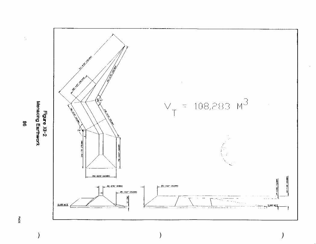
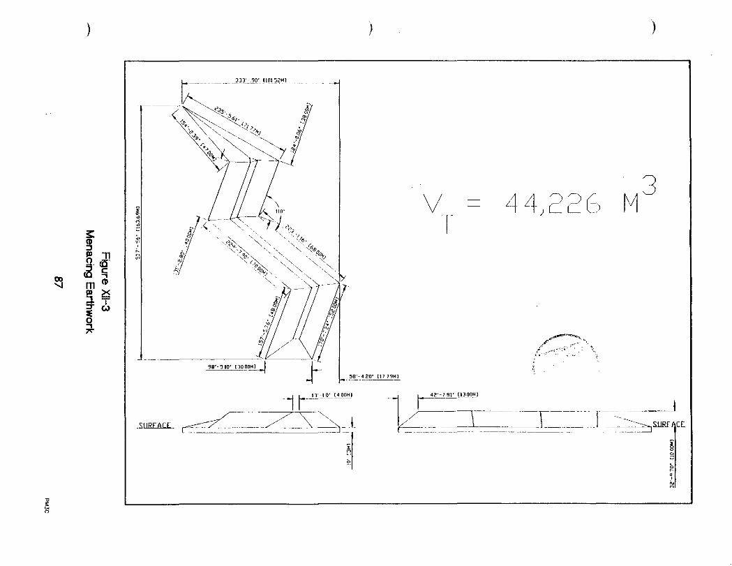


PASSIVE INSTITUTIONAL CONTROLS DESIGN REPORT REVISION 0
XIII. CONCEPT SELECTION
The following discussion addresses the I @qgtion of conceptual design B as the recomendedf\ae igg for permanently marking the site. *.
7L -r '
The distinguishing features of the individual designs considered are the berm configurations. This arises from the various configurations addressed in Trauth et. al., 1993. The quantity of material and general configuration of the berms give rise to a significant construction effort in their erection. For total quantity of material required, designs A and C each represent on the order of 1,400,000 cubic meters. Design B is approximately 750,000 cubic meters. In addition, the shape of the various berm sections for design C add an additional degree of construction complexity over that of designs A and B. Although design C is more *'menacing**, the actual warning of danger is conveyed effectively by the inscribed information on the monuments. The primary purpose of the berm is to convey the Level I message that something manmade is here. All of the berm configurations will perform this function. - Design A does not provide the degree of "protection" (i. e. , enclose the repository footprint) that is conveyed by either design B or C. It is acknowledged that access to much of the footprint is inhibited by an additional 10 meters of material when design A is considered. However, other than causing some additional effort to set up a drilling platform on the design A berm, it adds little when considering that the repository is 655 meters below the surface. The volume of material required to construct the Trefoil shaped berm is considerably more than that required to construct design B. In addition, design A would not provide the same degree of protection from wind drive erosion of the monuments as does design B. The proximity of the monuments to the berm in design B will provide more protection to at least one face of a monument than would be available to the more exposed monuments in design A. Although barriers can be erected to improve protection of the inscribed material there is no apparent advantage of the Trefoil over that of the perimeter berm. The elevated location of the Information Center at the center of the design A berm will also be subjected to greater wind driven erosion effects than the more protected location provided by design B berm.

6
PASSIVE INSTITUTIONAL CONTROLS DESIGN REPORT REVISION 0
The berm aspect of the three permanent marking concepts considered is the major design variable. The Monuments, the Information Center, the Storage Rooms, and the Subsurface Warning markers will not significantly vary in cost for any of the three configurations. When all the salient features including total materials required, ease o f construction, meeting design requirementslcriteria (Section 111), and establishing permanence are compared, the conceptual configuration using a rectangular berm to enclose the entire repository footprint is the most practicable. For this reason, Concept B is the configuration of choice for the Permanent Marker System.
PASSIVE INSTITUTIONAL CONTROLS DESIGN REPORT REVISION 6 -.
XIV. OFFSITE ARCHIVAL STORAGE *
Webster's Collegiate Dictionary defines archive-as 'a place in which public records or historical documents are preserved". This definition implies control of the environment, control of access to the records and documents, and control/selection of the storage medium. A significant part of the overall plan to provide PIC is the distribution of important information remote from the repository for preservation. The archived material should include information that is important to defining the location, design, content, and hazards associated with the WIPP. The documentation addressing the details of the WIPP site is extensive and quite voluminous. In that the space needs at the repository site would be extensive, it is not practicable to attempt to provide this information in a format suitable for inclusion within the marker system design itself. This information will be broader in scope and more extensive in volume than that available within the permanent marker system at the repository footprint location or record centers and should be widely distributed in a number of locations including some locations worldwide. To ensure that access to the most pertinent location, potential hazards I of intrusion, and land use restrictions information is readily available, the DOE will develop a WIPP summary document. This document will be distinctively bound. The receiving archive will be requested to locate and
' catalog this summary volume such that it is readily available to the general public with particular emphasis on availability to potential natural resource investigators, historians, and archaeologists. These summary documents will be prepared and translated into the six recognized United Nations languages. The receiving archive will determine which language version shall be archived. The initial form of the information should be on archival quality paper. Paper will be specified to meet or exceed the requirements of National Archives and Records Administration (NARA) Bulletin Number 95-7 (Bechtold, 1996) orANSI/NISO 239.48-1992 (or latest version), Permanence of Paper for Documents and Libraries to ensure that the stored records will have a maximum opportunity of surviving for thousands of years. In addition, offset printing using an oxidizing, carbon black ink with a buffered fountain solution (pH >5.5) or equivalent will be specified. Careful consideration should be given to the implications of permitting electronic storage technologies as archival storage
a . . ,,. .. ;*.'>'> i'
y - , . 4: : i 2.~ i> . h . 2, . , ',:: i"
PASSIVE INSTITUTIONAL CONTROLS DESIGN REPORT REVISION b,& %f 9'
k.--e"".*' mediums. No experience with the long term storage capabilities of the electronic technologies exist today. In addition, the equipment to read back these technologies could be lost in the future as new products become available.
Specific documents which should be included in the archived information portfolio to address the requirements of the regulations include:
1. The Final Safety Analysis Report (FSAR) and the addenda which describes the disposal phase of the WIPP.
2. The Final Environmental Impact Statement for WIPP and the Supplement(s) to the Environmental Impact Statement
3. The No-Migration Variance Petition and the No- Migration Determination for Disposal
4. The Resource Conservation and Recovery Act (RCRA) Permit
5 . The Certification of Demonstration of Compliance with Title 40 CFR 191
6. Environmental and ecological background data collected during the pre-operational phase of WIPP and summaries of data collected during the disposal and decommissioning phases of WIPP
7. Records of the waste containers contents and disposal locations within the WIPP repository
8. Drawings defining the construction and configuration of the repository and shafts
9. Drawings, procedures, and the design report (s) describing how the waste was emplaced; how the rooms, drifts, and panels were closed; and how the shafts were backfilled and sealed.
10. Detailed maps describing the exact location of the repository
11. Design, drawings, specifications, (etc.) for Permanent Markers.
PASSIVE INSTITUTIONAL CONTROLS DESIGN REPORT REVISION 0
Locations for this information should include public funded organizations which may be more likely to expend the resources necessary to preserve the documents in well controlled environments. However, the most likely strategy for long term protection of the information is through widespread distribution. The DOE will strive.$o reach agreements for accepting and archivingth documents with the following facilitieslorgani
National Archives and Records Services .... The State Archives of New Mexico and Texas ....-.He
The national archives of the nations worldwide which possess nuclear weapons and/or operate nuclear power generating plants (see Appendix 4) The archives of the United Nations The national archives of the world nations which possess natural gas and/or petroleum resources and are not included in the list of nations have nuclear weapons/nuclear power plants above (see Appendix 5)
To ensure the proper storage and retrievability of archived material, the DOE archivist will develop a -*
filing code system specifically for the WIPP material. This system will be a part of the overall document submittal DOE will provide to the various archival locations. As described above, the paper used to print the submitted documents will be archival quality.
To reduce the possibility that future archivists may destroy the provided documents, each volume containing documents will be labeled with a warning that the intent of providing the archived material is to ensure its preservation for the 10,000 year regulatory time frame stipulated in the United States Government's regulations controlling the disposal of Transuranic Waste. It is recognized that the Federal Government may incur some long term financial obligations to the archival locations to ensure retention. Within two years following the distribution of archival material and at least every 15 years thereafter duringthe Active Institutional Controls period, the DOE will conduct audits of selected archival locations to verify retention and retrievability of the historical documents.

;:. . . ;. 2 ... ,,. I : : ' i
C. 7 . V& 't' $.a > PASSIVE INSTITUTIONAL CONTROLS DESIGN REPORT REVISION ,$ %~!;+? !; r . . I
3\ t:; A:; , , ,
XV. RECORDS CENTERS \.-.
Record centers, for the purpose of making a distinction from archives, are locations which would generally permit freer access by members of the public and not normally exercise the degree of environmental control and information medium selection to be found in modern archives. Many of the centers would also not receive the same quantity of information allocated to archives. In that the record centers normally serve a more functional nature than do archives for individuals explicitly interested in resource exploitation rather than historical or archeological information, a smaller volume of documentation will be provided. Information provided to these record centers should be focused on location, design, and hazards information. The record centers should include various Federal and State librarieslagencies and commercial mapping agencies to ensure that the WIPP location and drilling or mining restrictions are identified on widely distributed maps used by almost all public and private organizations. These Federal and State Librarieslagencies include:
The New Mexico and Texas State Libraries The City Libraries of population centers exceeding 15,000 within 150 miles of the WIPP site The U.S. Nuclear Regulatory Commission The 53 Federal Regional Depository Libraries The state libraries of the remaining 48 states Bureau of Land Management U.S. Geological Survey Library of Congress Defense Mapping Agency International Boundary Commission Federal Highway Administration New Mexico State Highway Department Planning and Research Division, Cartography Section One-Call System of notification of underground utilities
The local office of the Bureau of Land Management The local office of the Bureau of Mines The local office of the Bureau of Reclamation The Federal records center serving New Mexico The Hobbs and Artesia offices of the New Mexico Oil Conservation Division (OCD) Supporting University Libraries ( e n New Mexico Tech, New Mexico State University, University of New Mexico, and Texas A&M)
PASSIVE INSTITUTIONAL CONTROLS DESIGN REPORT REVISION 0
It is intended that the quantity of documents provided to record centers be significantly reduced from that providedto archives. However, the information regarding design, location, hazards, and land use restrictions (see Section XVI) will still require a significant amount of storage shelf space. As with archival documentation, information provided to record centers will contain the admonition to preserve these records for the regulatory time frame. To ensure that access to the most pertinent location, potential hazards of intrusion, and land use restrictions information is readily available, the DOE will develop a WIPP summary document. This document will be distinctively bound. The receiving record centers will be requested to locate and catalog this summary volume such that it is readily available to the general public with particular emphasis on availability to potential natural resource investigators, historians, and archaeologists.

C PASSIVE INSTITUTIONAL CONTROLS DESIGN REPORT REVISION 0
XVI. OTHER PASSIVE INSTITUTIONAL CONTROLS
LOCATION MAPPING
To ensure wide spread location information of the WIPP site and the hazards associated with the emplaced waste, detailed maps and descriptions of the hazardous material will be sent to national and international professional societies of cartographers and geographers. Weitzburg 1982 suggests the following organizations and societies receive this location and hazards information:
The American Congress on Surveying and Mapping The American Society of Cartographers The Commission for the Geological Map of the World The International Cartographic Association The American Geographical Society The Association of American Geographers The International Geographical Union The Society of Women Geographers The American Geological Institute The American Geophysical Union The American Society of Professional Geographers The National Geographic Society The Federal Aviation Administration Mining, Oil, and Gas Professional Organizations
The actual distribution of the information will depend on agreements worked out between the DOE and these organizations and societies.
Many of the members of these various organizations are employed in secondary and college education providing an opportunity for this information to become more widely disseminated among students during their formal education. In addition, companies providing energy and resource related data to commercial ventures active in the Delaware Basin should receive location and hazardous record information. Examples of such companies include:
Midland Map Company of Midland, Texas Petroleum Information Corporation of Midland, Texas Tobin Data Graphics of Austin, Texas Dwight's Energy Data of Denver, Colorado
Location and hazards information should be submitted to various Federal and State of New Mexico mapping agencies to ensure that the WIPP location and drilling or mining

PASSIVE INSTITUTIONAL CONTROLS DESIGN REPORT REVISION 0
restrictions are identified on widely distributed maps used by almost all public and private organizations. These agencies include:
Bureau of Land Management 0 U.S. Geological Survey
Defense Mapping Agency International Boundary Commission k.
\ - * ' Federal Highway Administration .. " . -A/
New Mexico State Highway Department Planning and Research Division, Cartography Section One-Call System of notification of underground utilities
GOVERNMENT CONTROL
The United States Government controls the sixteen sections 15 through 22 and sections 27 through 34 of Township 22 South, Range 31 East in Eddy County, New Mexico which are included in the WIPP controlled area (see Figure V-4). Government control is a passive control providing for the transfer of information from record centers to any potential resource exploration or exploitation organization. It is expected that A
government control of the land withdrawal area will be retained for as long as a U.S. Government exists and this control will act as an awareness trigger for anyone contemplating resource exploitation within the controlled area. With government ownership of the resource leases pertainingtothe withdrawn sections, commercial resource exploration and development entities are essentially precluded from obtaining permission to drill or mine in and immediately around the repository. Any organization contemplating resource exploration within the controlled area would learn of the government control immediately upon initiating search of lease availability within the appropriate record center(s) pertaining to Eddy County New Mexico. This government control and the state permitting regulations governing drilling and mining preclude any activities within the withdrawn area that might intrude into the repository.
A recent review of the oil and gas well drilling records back to 1914 at the Hobbs and Artesia offices of the OCD failed to uncover a single incident wherein a driller set-up to drill in a location different from the location identified in the drilling permit. Staff members from each office, when queried, could not recall a single instance wherein a drilling operation occurred in a non- -,

C PASSIVE INSTITUTIONAL CONTROLS DESIGN REPORT REVISION 0
permitted location. Exploring this possibility further, four additional individuals (two consulting geologists, a petroleum engineer, and a surveying supervisor) with 14 to 44 years of individual experience in the Delaware Basin were also asked the question of drilling in the wrong location. Three instances, one about 30 years ago and two about 15 years ago, were recalled. None of these occurrences were in the Delaware Basin.
LAND USE RESTRICTION8
Within the controlled area all land use leases are retained by the Federal Government with the exception of two, 320 acre, oil and gas leases in section 31. Section 31 is the southwestern most section of the 16 sections withdrawn under the Land Withdrawal Act (LWA) of 1992. The two leases permit oil and gas development below 1829M (6000 feet) from the surface. Section 31 does not include the area planned for repository use.
The DOE has jurisdiction regarding land use. In accordance with the Land Withdrawal Act, the WIPP controlled area is " . . .withdrawn from all forms of entry, appropriation, and disposal under the public land laws, the material sale laws ... and mining laws". The objective of the DOE with respect to mining and oil and gas production is to ensure that the development of mineral leases does not affect the integrity of the disposal system. Accordingly, no surface or subsurface mining unrelated to the WIPP Project, or oil or gas production, including slant drilling from outside the boundaries of the LWA are permitted at any time, including post- decommissioning, with the exception of the two oil and gas leases in section 31 identified above. These leases prohibit drilling within the first 182911 (6,000 feet) of the surface(D0E 1993). However, the LWA does permit the Secretary of Energy to permit grazing, hunting, and trapping within the LWA.
ADDITIONAL CONTROLS
Other passive institutional controls that will be incorporated to contribute to maintaining society's knowledge of the WIPP location and cautions regarding the maintenance of its integrity include:
Incorporation of WIPP's location on various maps and

PASSIVE INSTITUTIONAL CONTROLS DESIGN REPORT REVISIOE~ - road atlases Description of WIPP's location and co the subject matter of encyclopedias
a Identification of WIPP as a geographical name in dictionaries Descriptions of WIPP incorporated within the text of high school and college level history books
a Development of a home page for the WIPP on the Internet (the current home page address for WIPP information is http//:wuw.wipp.carlsbad.nm.us)
An example of map identification of specific areas is the Rand McNally Safety Atlas, 1993. This atlas outlines areas designated as "Nevada Test Site" and 'Nellis Air Force Range" in Nevada and "Chocolate Mountain Gunnery Range" in Southern California. "White Sands Missile Rangen is also designated on the New Mexico map in the Atlas. Areas in western Nevada are designated by the generic warning "Danger Areaw.
+
,-- I. PASSIVE INSTITUTIONAL CONTROLS DESIGN REPORT REVISION 0 i \ - .
1 &. Quality Assurance and Quality Control disciplines should be applied to a number of aspects of the permanent marker procurement and construction efforts.
The basic permanent marker building material will be granite (radar reflectors will be encased in concrete) and can be subjected to QC inspection and testing to ensure that the final specifications for the material and its properties are met. In the case of the granite monuments and the granite slabs for fabrication of the storage rooms, the final products lend themselves to measurements and evaluation of cutting tolerances and alignment. The Storage Room design's use of granite without mortar or some other bonding material makes it prudent to have QC inspection at the quarry for verification of configuration alignment and tolerances prior to shipping the massive granite slabs and monuments. Similarly, the engraving of such a large quantity of letters and characters to provide the messages in different languages will offer a unique challenge to both the supplier and the DOE'S QA program.
It is anticipated that concrete will be used to construct the stairway over the berm as well as for encasing the radar reflectors. The testing techniques of individual pour characteristics is well established and can be applied where applicable to support that portion of the permanent marker construction effort.
Construction of the berms consisting of layers of materials and their compaction also lends itself to QC inspection techniques developed for the construction of earthen dams. Although permeability is not a concern for the permanent marker berms, other testing and measuring techniques can be applied for quantities of specified materials applied, required slopes, degree of compaction, and overall dimensional requirements.
QA/QC will also be applied to the fabrication of the small warning markers. These warning markers will be made of different materials to provide a higher level of confidence that no single adverse material characteristic will render all of the small warning markers ineffective over the prescribed 10,000 year design life required of the permanent marker system. Ceramic, granite, and fired

PASSIVE INSTITUTIONAL CONTROLS DESIGN REPORT REVISION 0
clay warning markers will be utilized in the small marker system.
QA/QC will be applied to the production of material submitted to record centers, libraries, and archives.
PASSIVE INSTITUTIONAL CONTROLS DESIGN REPORT REVISION 0 2
\: REFERENCES --%-d
Ahlen, J.; Ferguson F.; Jackson, D.; McVay, T.; Scott, L.; Sexton, J.; Wilson D.; Lewis P.; Brian, J.; Fowler, B.; 1995. Analytical Study of an Inadvertent Intrusion of the WIPP Site, WIPP Inadvertent Instrusion Advisory Panel and New Mexico Junior College, September 5, 1995
Bachman, G.O. 1985. Assessment of Near-Surface Dissolution at and near the Waste Isolation Pilot Plant (WIPP), southeastern New Mexico. SAND84-7178. Sandia National Laboratories, Albuquerque, NM . Bechtold, S.L. 1996 correspondence. National Archives and Records Administration (NARA) Bulletin No. 9 5 - 7 , September 8, 1995
Bellus, Peter A. : Jerome Eckerman. August 1994. Airborne or Spaceborne Surveillance radar detection of WIPP Site
Birkeland, Peter W. 1984: Soils and Geomorpholouy
Hora, Stephan C. 1991. Exuert Judcnnent on Inailvertent Human Intrusion into the Waste Isolation Pilot Plant. SAND90-3063oUC-721. - December 1991
Jensen, Mikael. 1993. Conservation and Retrieval of Information - Elements of a Stratem to Inform Future Societies about Nuclear Waste Re~ositories. Final Report of the Nordic Nuclear Safety Research Project KAN - 1.3. August 1993
Kaplan, Maureen F. 1982. Archaeoloaical Data as a Basis for Re~oSitory Marker Desian. ONWI-354oUC-70. October 1982.
Krefta, M. August 1994. Personal memorandum to T. Mallick titled Magnetic field calculations for WIPP maanetic markers
Mallick, Ted. August 1994. Personal memorandum to J. Iacovino titled WIPP Maanetic Markers
Nowak, E. J.; Tillerson, J. R.; Torres, T. M. 1990. Initial Reference seal System Desian: Waste Isolation Pilot Plant. SANDSO- 03550UC -721. May 1990
Swift, P.N. 1992. Lona-Term Climate Variabilitv at the Waste Isolation Pilot Plant. Southeastern New Mexico. USA. Environmental Management. SAND91-70550UC-721. November 1992.
Tolan, Terry L. 1993. The Use of Protective Barriers to Deter ,-
Inadvertent Human Intrusion Into a Mined Geoloaic facility for the
103
PASSIVE INSTITUTIONAL CONTROLB DEBIGN REPORT REVISION 0
DiSDoSal of Radioactive Waste: A Review of Previous Investiaations and Potential ConceDts. SAND91-7097mUC-721. June 1993
Trauth, Kathleen M.; Hora, Stephen C.; Guzowski, Robert V.; 1993. m e r t Judament on Markers to Deter Inadvertent Human Intrusion into the Waste Isolation Pilot Plant. SAND92-1382mUC-721. November 1993
Weitzberg, Abraham. Buildina on Existinq Institutions to Per~etuate Waste Repositories. ONWI-379mUC-70 I WP 02-9,Revision 0, WIPP Final Saf v Analysis Re~ort, May 1990
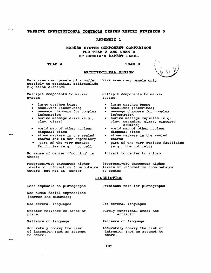
- PASSIVE INSTITUTIONAL CONTROLS DESIGN REPORT REVISION 0
APPENDIX 1
MARKER 8YSTEM COMPONENT COMPARISON FOR TEAM A AND TEAM B
OF SANDIA'S EXPERT PANEL
ARCHITECTURAL DESIGN
Mark area over panels plus buffer Hark area over panels & possibly to potential radionuclide migration distance
Multiple components to marker system . large earthen berms . monoliths (inscribed)
message chambers for complex information buried message disks (e-g., clay, glass)
world map of other nuclear disposal sites
.- . stone markers in the sealed shafts and in the repository part of the WIPP surface facilities (e-g., hot cell)
No sense of center ("nothing" is there)
Multiple components to marker system
large earthen berms monoliths (inscribed) . message chambers for complex information buried message capsules (e.g. clay, ceramics, glass, sintered
alumina) world map of other nuclear disposal sites stone markers in the sealed shafts . part of the WIPP surface facilities (e.g., the hot cell)
Attract to center to inform
Progressively encounter higher Progressively encounter higher levels of information from outside levels of information from outside toward (but not at) center to center
LINGUISTICS
Less emphasis on pictographs Prominent role for pictographs
use human facial expressions (horror and sickness)
Use several languages Use several languages
Greater reliance on sense of Purely functional area; not place artistic
Reliance on language Reliance on language
Accurately convey the risk Accurately convey the risk of of intrusion (not an attempt intrusion (not an attempt to to scare) scare)
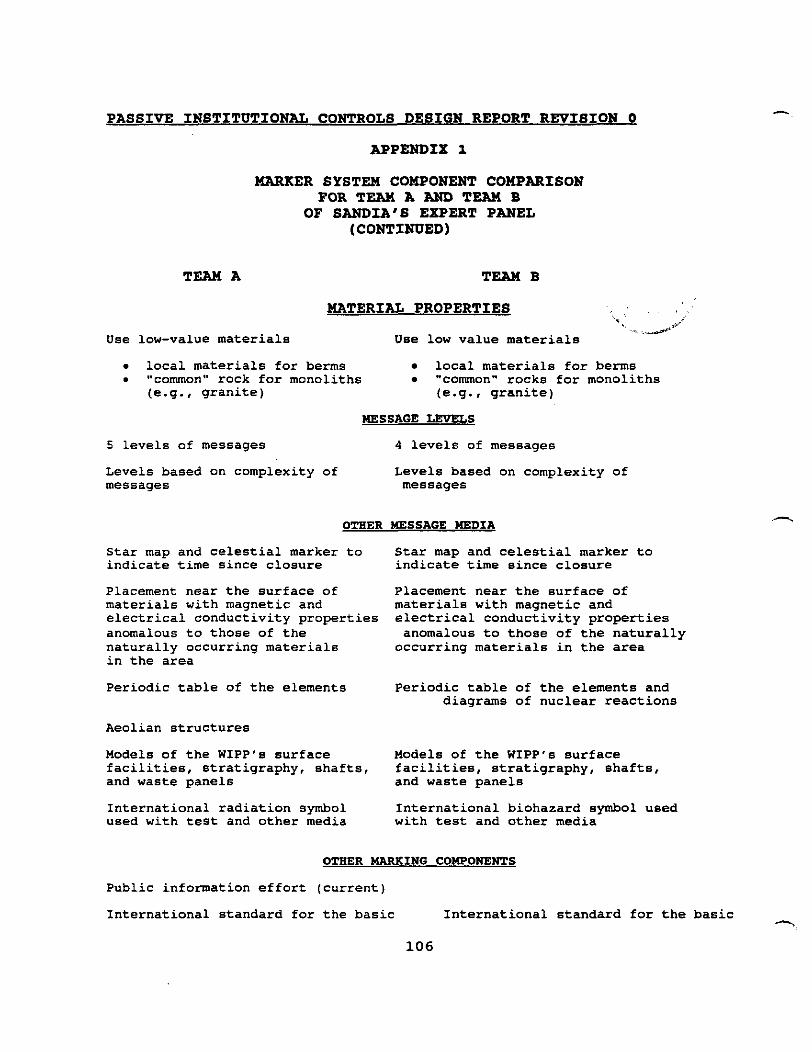
PASSIVE INSTITUTIONAL CONTROLS DESIGN REPORT REVISION 0
APPENDIX 1
m K E R SYSTEM COMPONENT COMPARISON FOR TEAM A AND TEAM B
OF SANDIA'S EXPERT PANEL (CONTINUED)
TEAM A TEAM B
MATERIAL PROPERTIES -. - r^ar" #'
Use low-value materials Use low value materials
local materials for berms local materials for berms "common" rock for monoliths "common" rocks for monoliths (e.g., granite) (e.g., granite)
MESSAGE LEVELS
5 levels of messages 4 levels of messages
Levels based on complexity of Levels based on complexity of messages messages
OTHER MESSAGE MEDIA
Star map and celestial marker to indicate time since closure
Placement near the surface of materials with magnetic and electrical conductivity properties anomalous to those of the naturally occurring materials in the area
Periodic table of the elements
Aeolian structures
Models of the WIPP's surface facilities, stratigraphy, shafts, and waste panels
International radiation symbol used with test and other media
Star map and celestial marker to indicate time since closure
Placement near the surface of materials with magnetic and electrical conductivity properties anomalous to those of the naturally
occurring materials in the area
Periodic table of the elements and diagrams of nuclear reactions
Models of the WIPP's surface facilities, stratigraphy, shafts, and waste panels
International biohazard symbol used with test and other media
OTHER MRRKING COMPONENTS
Public information effort (current)
International standard for the basic International standard for the basic

- PASSIVE INSTITUTIONAL CONTROLS DESIGN REPORT REVISION 0
design features for long-term marking design features for long-term
APPENDIX 1
MARKER SYSTM COMPONENT COMPARISON FORTEAWAANDTEAWB
OF SANDIA'S EXPERT PANEL (CONTINUED)
TEAM A TEAMB marking
Testing for the longevity of markers Testing for the longevity of markers and the interpretability of messages and the intepretability of messages across cultures across cultures
Off-site archives Off-site archives

PASSIVE INSTITUTIONAL CONTROLS DESIGN REPORT REVISION 0
APPENDIX 2
LEVEL 11, 111, AND IV MESSAGES FOR MONUMENTS AND STORAGE ROOMS
LEVEL I1 MESSAGES:
2. POISONOUS RADIOACTIVE 9 WASTE HERE
3. DO NOT DIG OR DRILL.
LEVEL I11 MESSAGE:
THESE STRUCTURES MARK AN AREA USED TO BURY HAZARDOUS MATERIALS AND RADIOACTIVE 9 WASTES. THE AREA IS 660 METERS BY 810 METERS AND THE WASTE IS BURIED 655 METERS DOWN. THIS PLACE WAS CHOSEN TO PUT THESE DANGEROUS MATERIALS FAR AWAY FROM PEOPLE AND OTHER LIVING THINGS. THE ROCK AND WATER IN THIS AREA MAY NOT LOOK, FEEL, OR SMELL UNUSUAL, BUT MAY BE POISONED BY HAZARDOUS MATERIALS AND RADIOACTIVE 9 WASTES. WHEN RADIOACTIVE 9 MATTER DECAYS, IT GIVES OFF INVISIBLE ENERGY THAT CAN DESTROY OR DAMAGE PEOPLE, ANIMALS, AND PLANTS.
DO NOT DRILL HERE. DO NOT DIG HERE. DO NOT DO ANYTHING WITH THE ROCKS OR WATER IN THE AREA.
DO NOT DESTROY THIS MARKER. THIS MARKING SYSTEM HAS BEEN DESIGNED TO LAST 10,000 YEARS. IF THE MARKER IS DIFFICULT TO READ, ADD NEW MARKERS IN LONGER-LASTING MATERIALS AND COPY THIS MESSAGE IN YOUR LANGUAGE ONTO THEM.
THE SITE WAS KNOWN AS THE WIPP (WASTE ISOLATION PILOT PLANT) SITE WHEN IT WAS CLOSED IN 2030 A.D. FOR MORE INFORMATION, GO TO THE BUILDING AT THE CENTER OF THIS MARKED AREA. IF THE MESSAGES WITHIN THE INFORMATION CENTER ARE UNUSABLE, THEY HAVE BEEN DUPLICATED IN A ROOM BURIED 6 METERS DEEP 160 METERS NORTH OF THE BERM ON A LINE PASSING THROUGH THE INFORMATION CENTER, THE CENTER OF THE NORTH AND SOUTH SECTIONS OF THE BERM, AND THE HOT CELL CONCRETE ARTIFACT STANDING APPROXIMATELY 320 METERS NORTH OF THE BERM CENTER LINE. THE ROOM LOCATION IS ALSO MARKED BY A MAGNETIC SIGNATURE. DO NOT EXPOSE THIS ROOM UNLESS THE INFORMATION CENTER MESSAGES ARE LOST. LEAVE THE ROOM BURIED FOR FUTURE GENERATIONS. IF THE ROOM BECOMES EXPOSED, PROTECT IT BY ADDITIONAL COVERING.
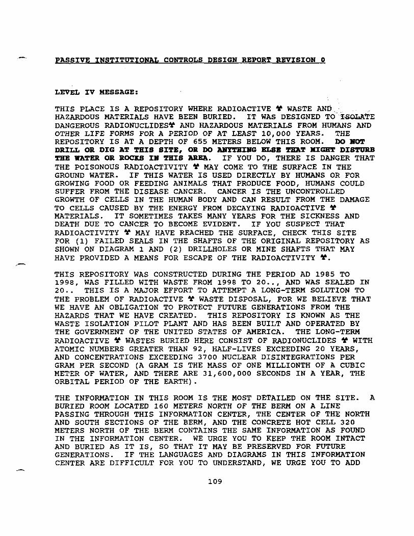
- PASSIVE INSTITUTIONAL CONTROLS DESIGN REPORT REVISION 0
LEVEL IV MESSAGE:
THIS PLACE IS A REPOSITORY WHERE RADIOACTIVE Y WASTE AND HAZARDOUS MATERIALS HAVE BEEN BURIED. IT WAS DESIGNED TO I-SOWLVE DANGEROUS RADIONUCLIDESY AND HAZARDOUS MATERIALS FROM HUMANS AND OTHER LIFE FORMS FOR A PERIOD OF AT LEAST 10,000 YEARS. THE REPOSITORY IS AT A DEPTH OF 655 METERS BELOW THIS ROOM. DO HOT DRILL OR DIG AT THIS SITE, OR DO m G ELSE TEAT MIGHT DISTURB THE WATXR OR ROCKS IH THIS AREA. IF YOU DO, THERE IS DANGER THAT THE POISONOUS RADIOACTIVITY 9 MAY COME TO THE SURFACE IN THE GROUND WATER. IF THIS WATER IS USED DIRECTLY BY HUMANS OR FOR GROWING FOOD OR FEEDING ANIMALS THAT PRODUCE FOOD, HUMANS COULD SUFFER FROM THE DISEASE CANCER. CANCER IS THE UNCONTROLLED GROWTH OF CELLS IN THE HUMAN BODY AND CAN RESULT FROM THE DAMAGE TO CELLS CAUSED BY THE ENERGY FROM DECAYING RADIOACTIVE 9 MATERIALS. IT SOMETIMES TAKES MANY YEARS FOR THE SICKNESS AND DEATH DUE TO CANCER TO BECOME EVIDENT. IF YOU SUSPECT THAT RADIOACTIVITY 9 MAY HAVE REACHED THE SURFACE, CHECK THIS SITE FOR (1) FAILED SEALS IN THE SHAFTS OF THE ORIGINAL REPOSITORY AS SHOWN ON DIAGRAM 1 AND (2) DRILLHOLES OR MINE SHAFTS THAT MAY HAVE PROVIDED A MEANS FOR ESCAPE OF THE RADIOACTIVITY 9.
,-
THIS REPOSITORY WAS CONSTRUCTED DURING THE PERIOD AD 1985 TO 1998, WAS FILLED WITH WASTE FROM 1998 TO 20.., AND WAS SEALED IN 20.. THIS IS A MAJOR EFFORT TO ATTEMPT A LONG-TERM SOLUTION TO THE PROBLEM OF RADIOACTIVE * WASTE DISPOSAL, FOR WE BELIEVE THAT WE HAVE AN OBLIGATION TO PROTECT FUTURE GENERATIONS FROM THE HAZARDS THAT WE HAVE CREATED. THIS REPOSITORY IS KNOWN AS THE WASTE ISOLATION PILOT PLANT AND HAS BEEN BUILT AND OPERATED BY THE GOVERNMENT OF THE UNITED STATES OF AMERICA. THE LONG-TERM RADIOACTIVE 9 WASTES BURIED HERE CONSIST OF RADIONUCLIDES Y WITH - - - - - - - - - - ~~ - - - - - -
ATOMIC NUMBERS GREATER THAN 92, HALF-LIVES EXCEEDING 20 YEARS, AND CONCENTRATIONS EXCEEDING 3700 NUCLEAR DISINTEGRATIONS PER GRAM PER SECOND (A GRAM IS THE MASS OF ONE MILLIONTH OF A CUBIC METER OF WATER, AND THERE ARE 31,600,000 SECONDS IN A YEAR, THE ORBITAL PERIOD OF THE EARTH).
THE INFORMATION IN THIS ROOM IS THE MOST DETAILED ON THE SITE. A BURIED ROOM LOCATED 160 METERS NORTH OF THE BERM ON A LINE PASSING THROUGH THIS INFORMATION CENTER, THE CENTER OF THE NORTH AND SOUTH SECTIONS OF THE BERM, AND THE CONCRETE HOT CELL 320 METERS NORTH OF THE BERM CONTAINS THE SAME INFORMATION AS FOUND IN THE INFORMATION CENTER. WE URGE YOU TO KEEP THE ROOM INTACT AND BURIED AS IT IS, SO THAT IT MAY BE PRESERVED FOR FUTURE GENERATIONS. IF THE LANGUAGES AND DIAGRAMS IN THIS INFORMATION CENTER ARE DIFFICULT FOR YOU TO UNDERSTAND, WE URGE YOU TO ADD

PASSIVE INSTITUTIONAL CONTROLS DESIGN REPORT REVISION 0 -
NEW TRANSLATIONS OF OUR TEXTS FOR THE BENEFIT OF FUTURE GENERATIONS. THIS SHOULD BE DONE FOR TEXTS IN THIS ROOM AND THROUGHOUT THE SITE; ALSO ADD NEW MARKERS AND OTHER STRUCTURES IF NECESSARY TO MAINTAIN THE MARKING SYSTEM IN GOOD, EFFECTIVE CONDITION. HOWEVER, DO NOT DEFACE OR REMOVE THE ORIGINAL TEXTS, DIAGRAMS, OR MARKERS, FOR THEY WILL REMAIN VALUABLE TO FUTURE PERSONS TRYING TO UNDERSTAND YOUR OWN TRANSLATIONS AND ADDITIONS. IF YOU WANT MORE INFORMATION THAN IS AVAILABLE IN THIS ROOM, SEARCH IN HISTORICAL AND ARCHAEOLOGICAL LIBRARIES, MUSEUMS, AND ARCHIVES APPROPRIATE TO OUR TIME.
THE SALT BED AT THIS SITE AT A DEPTH OF 655 METERS IS ABOUT 220 MILLION YEARS OLD AND IS CONSIDERED VERY STABLE ON A TIME-SCALE OF 10,000 YEARS AGAINST GEOLOGICAL EVENTS SUCH AS EARTHQUAKES AND VOLCANISM. DIAGRAM 1 AND 2 SHOW THE GEOLOGICAL STRATA AT THIS SITE AND THE LOCATION OF THE REPOSITORY. SALT IS CONSIDERED A GOOD MEDIUM FOR THE PERMANENT STORAGE OF THESE WASTES BECAUSE ITS PRESENCE INDICATES A LACK OF CIRCULATING GROUNDWATER, IT IS EASY TO MINE, AND IT IS MOBILE IN THE SENSE THAT IT RELATIVELY QUICKLY SEALS ANY FRACTURES OR VOIDS, SUCH AS THOSE OF A WASTE REPOSITORY. THE SITE IS ALSO CONSIDERED ACCEPTABLE IN THAT FEW RESOURCES ATTRACTIVE FOR EXTRACTION ARE KNOWN IN THE VICINITY. THE MAIN SUCH RESOURCES KNOWN IN THIS REGION ARE OIL, NATURAL GAS, AND POTASH. THE SITE ALSO IS NOT ASSOCIATED WITH ANY -j
POTABLE AQUIFER AND HAS A VERY DRY CLIMATE (0.3 M OF RAIN PER YEAR); MOREOVER, WE EXPECT THE CLIMATE TO REMAIN DRY OVER THE NEXT 10,000 YEARS.
THE REPOSITORY AS CONSTRUCTED CONSISTED OF A SERIES OF ROOMS CARVED OUT OF THE SALT, EACH ABOUT 10-M WIDE BY 4-M HIGH BY 100-M LONG. THE ROOMS COVERED A TOTAL AREA OF APPROXIMATELY 625 M BY 800 M (DIAGRAM 3) AND WERE ACCESSED BY A WASTE SHAFT APPROXIMATELY 7 M IN DIAMETER. THE WASTE SHAFT WAS TO THE IMMEDIATE WEST OF THE CONCRETE HOT CELL SHOWN IN DIAGRAM 3. FROM THE BOTTOM OF THE WASTE SHAFT, ACCESS TO THE ROOMS WAS ALONG TUNNELS OR DRIFTS WITH CROSS SECTIONS OF APPROXIMATELY 8-M BY 4- M. OTHER SHAFTS WERE PROVIDED FOR REMOVAL OF SALT, AND FOR AIR INTAKE AND EXHAUST. ALTOGETHER OVER 800,000 BARRELS, EACH OF VOLUME OF 0.2 CUBIC METERS, WERE BROUGHT TO THIS SITE IN ABOUT 20,000 TRUCK SHIPMENTS. THE AVERAGE MASS OF A BARREL IS .... GRAMS. THE BARRELS CONTAIN MOSTLY ORDINARY ITEMS THAT BECAME RADIOACTIVE 9 AND CONTAMINATED WITH HAZARDOUS MATERIALS AT SOME STAGE IN THE DEVELOPING, TESTING, CONSTRUCTING, AND RENEWING OF NUCLEAR WEAPONS. BURIED ITEMS INCLUDE RAGS, CLOTHING, BAGS, AND CONTAINERS; THESE ARE MADE OF FABRICS, PLASTIC, GLASS, AND METAL. THERE ARE ALSO COMPLEX MACHINES SUCH AS MOTORS, HAND TOOLS, AND MACHINE TOOLS. ABOUT 60 PERCENT OF THE RADIOACTIVE 9 WASTE ALSO CONTAINS HAZARDOUS CHEMICAL WASTES SUCH AS LEAD,

- PASSIVE INSTITUTIONAL CONTROLS DESIGN REPORT REVISION 0
CADMIUM, CHROMIUM, BARIUM, METHYLENE CHLORIDE (CH2C12), AND TOLUENE (C6H5CH3). MOST OF THE RADIOACTIVE * WASTE HAS MINIMAL EMISSIONS OF GAMMA RAYS, BUT ABOUT 3 PERCENT HAS ENOUGH GAMMA-RAY EMISSION THAT IT HAD TO BE REMOTELY HANDLED AT ALL STAGES, WITH HUMANS WELL REMOVED FROM THE CONTAINERS. THE ESTIMATED AMOUNT AT ,
THE TIME OF BURIAL OF THE MAJOR RADIONUCLIDES 9 BURIED HERE IS: NEPTUNIUM-237 (... GRAMS, EACH WITH ... NUCLEAR DISINTEGRATIONS PER SECOND, HALF-LIFE OF 2,100,000 YEARS); PLUTONIUM-238 (... GRAMS, EACH WITH ... NUCLEAR DISINTEGRATIONS PER SECOND, HALF- LIFE OF 88 YEARS); PLUTONIUM-239 (... GRAMS, EACH WITH ... NUCLEAR DISINTEGRATIONS PER SECOND, HALF-LIFE OF 24,000 YEARS) ; PLUTONIUM-240 (... GRAMS, EACH WITH ... NUCLEAR DISINTEGRATIONS PER SECOND, HALF-LIFE OF 6,500 YEARS); AMERICIUM-241 ( . .. GRAMS, EACH WITH ... NUCLEAR DISINTEGRATIONS PER SECOND, HALF-LIFE OF 432 YEARS) ; AMERICIUM-243 ( . . . GRAMS, EACH WITH . . . NUCLEAR DISINTEGRATIONS PER SECOND, HALF-LIFE OF 7,380 YEARS); CURIUM-244 (... GRAMS, EACH WITH ... NUCLEAR DISINTEGRATIONS PER SECOND, HALF-LIFE OF 18 YEARS); AND URANIUM-233 (... GRAMS, EACH WITH ... NUCLEAR DISINTEGRATIONS PER SECOND, HALF-LIFE OF 158,000 YEARS). WE ESTIMATE THAT AFTER 10,000 YEARS THE TOTAL NUMBER OF DISINTEGRATIONS IN THE BURIED WASTE HERE WILL BE REDUCED TO ... PER SECOND, WHICH MEANS THAT SOMEONE STANDING NEXT TO THIS WASTE WOULD ENCOUNTER A LEVEL OF RADIOACTIVITY 9 CORRESPONDING TO ..
C PERCENT OF THE NATURAL BACKGROUND AT THE SURFACE, OR ABOUT THE AMOUNT CORRESPONDING TO TYPICAL URANIUM ORE. DIAGRAM 4 IS A PERIODIC TABLE OF THE ELEMENTS, WITH THE RADIOACTIVE ? ELEMENTS INDICATED BY THE INTERNATIONAL "RADIOACTIVITY HAZARD" SYMBOL "9" THAT HAS BEEN USED IN OUR TIME SINCE 1950. ELEMENTS WITH A LARGE AMOUNT OF RADIONUCLIDES 9 BURIED HERE ARE ALSO MARKED WITH A "ml' THAT MEANS "RADIOACTIVE 9 WASTE BURIED HERE"; THESE SYMBOLS ARE THEN CONNECTED BY LINES TO THE REPOSITORY, SEE DIAGRAM 3. THESE TWO SYMBOLS HAVE ALSO BEEN USED WIDELY ELSEWHERE IN OUR MARKING SYSTEM. NON-RADIOACTIVE, CHEMICALLY TOXIC ELEMENTS BURIED HERE ARE INDICATED WITH A CIRCLE ON DIAGRAM 4. A DOWNWARD-POINTING
IN A TRIANGLE IS USED IN THE MARKING SYSTEM TO INDICATE THAT "BIOHAZARD MATERIAL IS BURIED HERE".
EACH ROOM WAS FILLED WITH BARRELS OF WASTE AND BACKFILLED WITH..... . GROUPS OF SEVEN ROOMS WERE EACH CLOSED SEALED WITH CEMENT PLUGS AND RECONSOLIDATED SALT. UPON COMPLETE FILLING OF THE REPOSITORY IN AD 2030 EACH OF THE FOUR SHAFTS TO THE SURFACE WAS SEALED WITH A SERIES OF MATERIALS, DIAGRAM 1, TOPPED BY A CONCRETE CAP ..M THICK. THE WASTE ROOMS ARE EXPECTED TO COLLAPSE FROM THE WEIGHT OF ROCK ABOVE THEM WITHIN 100 YEARS AND THE STEEL BARRELS WILL BREAK. THE SALT IS EXPECTED TO PREVENT THE

PASSIVE INSTITUTIONAL CONTROLS DESIGN REPORT REVISION 0
RADIONUCLIDES 9 FROM ESCAPING TO THE SURFACE; THE EXPECTED OUTWARD DIFFUSION INTO THE SALT IS ONLY .. METERS PER YEAR. WE BELIEVE THAT THE GREATEST POSSIBILITY FOR RADIONUCLIDES 9 TO MAKE THEIR WAY TO THE SURFACE IS THROUGH HUMAN INTRUSION, AND HENCE WE HAVE DESIGNED AND BUILT AN EXTENSIVE MARKING SYSTEM TO WARN YOU OF THE DANGERS. DO HOT DRILL OR DIG AT THIS SITE, W NOT DO ANYTHING ELBE TEAT HI- DISTURB THE WATER OR ROCKS I B l THIS AREA. WE BELIEVE THAT THE MOST LIKELY TYPE OF ACCIDENTAL INTRUSION IS DRILLING A HOLE THAT PENETRATES BOTH THE REPOSITORY AND THE SALTY WATER THAT MAY EXIST AT SOME LEVELS ABOVE AND BELOW THE REPOSITORY. THIS WATER MAY THEN BECOME CONTAMINATED AND REACH THE SURFACE THROUGH THE DRILLHOLE.
A MAP OF THE MARKER SYSTEM IS GIVEN IN DIAGRAM 5. THE ALIGNMENTS SHOWN ON THE MAP TOWARD THE AZIMUTH ANGLES OF 110 DEGREES, 160 DEGREES, 66 DEGREES, AND 42 DEGREES CORRESPOND TO THE LOCATIONS WHERE THE FOUR BRIGHTEST STARS NOW VISIBLE FROM THIS SITE RISE: SIRIUS, CANOPUS, ARCTURUS, AND VEGA. BECAUSE OF PRECESSION OF THE POLES, THESE STAR-RISE LOCATIONS CONSTANTLY CHANGE AND THUS A MEASUREMENT OF THESE ALIGNMENTS ALLOWS AN ACCURATE DATING OF THIS SITE.
IN ORDER TO INCREASE THE CHANCES OF SUCCESSFUL TRANSMISSION, THE DETAILS OF THE MESSAGE HAVE BEEN GIVEN MANY DIFFERENT, REDUNDANT FORMS, IN MATERIALS, LOCATIONS, LANGUAGES, GRAPHICS, AND AMOUNT OF DETAIL. MOST COMMON IS THE APPROXIMATELY 10-WORD BASIC MESSAGE FLANKED BY TWO HUMAN FACES, WHICH WE BELIEVE WILL CARRY FOR DISTANT FUTURE GENERATIONS THE SAME EFFECT AS FOR US. THE -
u THE RIGHT CONVEYS THE PRESENCE OF SOMETHING NAUSEOUS OR POISONOUS
ONE ON THE LEFT CONVEYS HORROR AND TERROR
1 . IN THIS MESSAGE THE INTERNATIONAL l%ADIOACTIVITY
HAZARD" SYMBOL 9 IS INTRODUCED BY PLACING IT NEXT TO THE WORD "RADIOACTIVE" 9. THIS MESSAGE ALSO INTRODUCES THE SYMBOL FOR TOXIC MATERIAL WITHIN AN ARROW POINTING DOWN. THE ARROW INDICATES THAT THE RADIOACTIVE 9 AND HAZARDOUS MATERIAL IS BELOW THE GROUND, NOT ON THE SURFACE. THIS AND ALL OTHER MESSAGES ARE GIVEN IN THE FOLLOWING SIX LANGUAGES, WHICH ARE THE OFFICIAL LANGUAGES OF THE UNITED NATIONS ORGANIZATION: CHINESE, RUSSIAN, ENGLISH, SPANISH, ARABIC, AND FRENCH. WE ALSO PROVIDE
G,$.
@ AND THE ONE ON
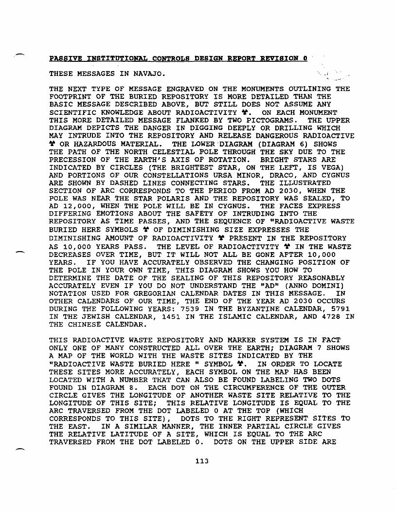
A
PASSIVE INSTITUTIONAL CONTROLS DESIGN REPORT REVISION 0
THESE MESSAGES IN NAVAJO.
THE NEXT TYPE OF MESSAGE ENGRAVED ON THE MONUMENTS OUTLINING THE FOOTPRINT OF THE BURIED REPOSITORY IS MORE DETAILED THAN THE BASIC MESSAGE DESCRIBED ABOVE, BUT STILL DOES NOT ASSUME ANY SCIENTIFIC KNOWLEDGE ABOUT RADIOACTIVITY *. ON EACH MONUMENT THIS MORE DETAILED MESSAGE FLANKED BY TWO PICTOGRAMS. THE UPPER DIAGRAM DEPICTS THE DANGER IN DIGGING DEEPLY OR DRILLING WHICH MAY INTRUDE INTO THE REPOSITORY AND RELEASE DANGEROUS RADIOACTIVE 9 OR HAZARDOUS MATERIAL. THE LOWER DIAGRAM (DIAGRAM 6) SHOWS THE PATH OF THE NORTH CELESTIAL POLE THROUGH THE SKY DUE TO THE PRECESSION OF THE EARTH'S AXIS OF ROTATION. BRIGHT STARS ARE INDICATED BY CIRCLES (THE BRIGHTEST STAR, ON THE LEFT, IS VEGA) AND PORTIONS OF OUR CONSTELLATIONS URSA MINOR, DRACO, AND CYGNUS ARE SHOWN BY DASHED LINES CONNECTING STARS. THE ILLUSTRATED SECTION OF ARC CORRESPONDS TO THE PERIOD FROM AD 2030, WHEN THE POLE WAS NEAR THE STAR POLARIS AND THE REPOSITORY WAS SEALED, TO AD 12,000, WHEN THE POLE WILL BE IN CYGNUS. THE FACES EXPRESS DIFFERING EMOTIONS ABOUT THE SAFETY OF INTRUDING INTO THE REPOSITORY AS TIME PASSES, AND THE SEQUENCE OF "RADIOACTIVE WASTE BURIED HERE SYMBOLS 9 OF DIMINISHING SIZE EXPRESSES THE DIMINISHING AMOUNT OF RADIOACTIVITY 9 PRESENT IN THE REPOSITORY - AS 10,000 YEARS PASS. THE LEVEL OF RADIOACTIVITY 9 IN THE WASTE DECREASES OVER TIME, BUT IT WILL NOT ALL BE GONE AFTER 10,000 YEARS. IF YOU HAVE ACCURATELY OBSERVED THE CHANGING POSITION OF THE POLE IN YOUR OWN TIME, THIS DIAGRAM SHOWS YOU HOW TO DETERMINE THE DATE OF THE SEALING OF THIS REPOSITORY REASONABLY ACCURATELY EVEN IF YOU DO NOT UNDERSTAND THE "AD" (ANN0 DOMINI) NOTATION USED FOR GREGORIAN CALENDAR DATES IN THIS MESSAGE. IN OTHER CALENDARS OF OUR TIME, THE END OF THE YEAR AD 2030 OCCURS DURING THE FOLLOWING YEARS: 7539 IN THE BYZANTINE CALENDAR, 5791 IN THE JEWISH CALENDAR, 1451 IN THE ISLAMIC CALENDAR, AND 4728 IN THE CHINESE CALENDAR.
THIS RADIOACTIVE WASTE REPOSITORY AND MARKER SYSTEM IS IN FACT ONLY ONE OF MANY CONSTRUCTED ALL OVER THE EARTH; DIAGRAM 7 SHOWS A MAP OF THE WORLD WITH THE WASTE SITES INDICATED BY THE "RADIOACTIVE WASTE BURIED HERE " SYMBOL 9. IN ORDER TO LOCATE THESE SITES MORE ACCURATELY, EACH SYMBOL ON THE MAP HAS BEEN LOCATED WITH A NUMBER TEAT CAN ALSO BE FOUND LABELING TWO DOTS FOUND IN DIAGRAM 8. EACH DOT ON THE CIRCUMFERENCE OF THE OUTER CIRCLE GIVES THE LONGITUDE OF ANOTHER WASTE SITE RELATIVE TO THE LONGITUDE OF THIS SITE; THIS RELATIVE LONGITUDE IS EQUAL TO THE ARC TRAVERSED FROM THE DOT LABELED 0 AT THE TOP (WHICH CORRESPONDS TO THIS SITE), DOTS TO THE RIGHT REPRESENT SITES TO THE EAST. IN A SIMILAR MANNER, THE INNER PARTIAL CIRCLE GIVES THE RELATIVE LATITUDE OF A SITE, WHICH IS EQUAL TO THE ARC TRAVERSED FROM THE DOT LABELED 0. DOTS ON THE UPPER SIDE ARE

PASSIVE INSTITUTIONAL CONTROLS DESIGN REPORT REVISION 0
SITES TO THE NORTH. THE FABRICATION OF THESE PANELS (ACCURACY OF 1 MM) HAS BEEN SUCH THAT WE BELIEVE THAT YOU CAN DETERMINE THE LOCATION OF ALL OTHER RADIOACTIVE * WASTE SITES FROM OUR TIME TO AN ACCURACY OF ABOUT 4 KM. WE URGE YOU TO CHECK THESE LOCATIONS AROUND THE WORLD AND MAKE CERTAIN THAT THE MARKINGS SYSTEMS FOR THESE OTHER SITES ARE IDENTICAL TO THOSE HERE. THE INTERNATIONAL STANDARD FOR THESE MARKING SYSTEMS CAN BE SUMMARIZED THUS:
"EACH SITE MUST (I) DISPLAY ITS BASIC WARNING MESSAGES IN AT LEAST TEE FOLLOWING LANGUAGES: CHINESE, RUSSIAN, ENGLISH, SPANISH, FRENCH AND ARABIC; (2) PROMINENTLY DISPLAY THE SYMBOL FOR INTERNATIONAL RADIOACTIVE WASTE BURIAL 9: (3) DISPLAY IN A PROTECTED CHAMBER A WORLD MAP OF ALL DISPOSAL SITES, TOGETHER WITH A STANDARD DIAGRAM THAT GEOMETRICALLY ALLOWS THEIR LOCATION TO AN ACCURACY OF AT LEAST 4 EX; AND (4) INCLUDE EARTHEN BERMS TO DELINEATE THE DISPOSAL AREA WITH HEIGHTS OF AT LEAST 10 M."
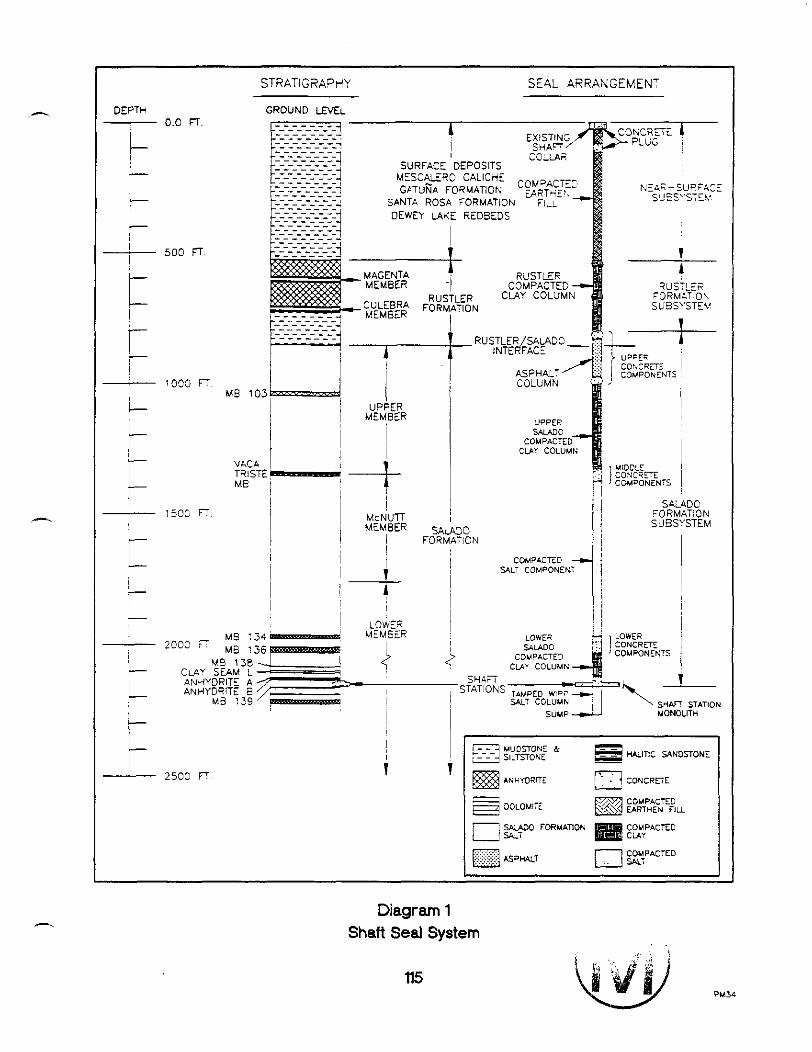
DEPTH
7 0.0 FT.
S A L A D 0 FORMATiON
j S U B S Y S T E M
! I ! COMPACEC
i i
! LOWS MS :34- MEMSER
! C,AV SEAM L --C==i
CLAY COLUMN - I ANHYDRITE A 7 - L ANHYDRITE B I
M B ? 3C '7 I 1 SHAV STATION i MONOLITH
EARTHEN FIW
Diagram 1 Shaft Seal System
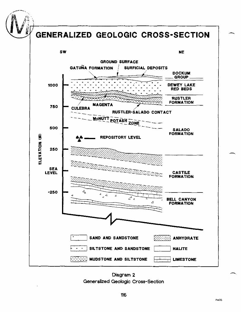
GROUND SURFACE
G A T U ~ A FORMATION / SURFICIAL DEPOSITS , I / - DOCKUM - -GROUP -
DEWEY LAKE
--- I ---
SALAD0 FORMATION
A . - REPOSITORY LEVEL A
CASTILE FORMATION
BELL CANYON FORMATION
7 SAND AND SANDSTONE p-2 ANHYDRATE
SILTSTONE AND SANDSTONE / HALITE
~I-T-I-I--I-! MUDSTONE AND SILTSTONE -1 LIMESTONE
Diagram 2 Generalized Geologic Cross-Section

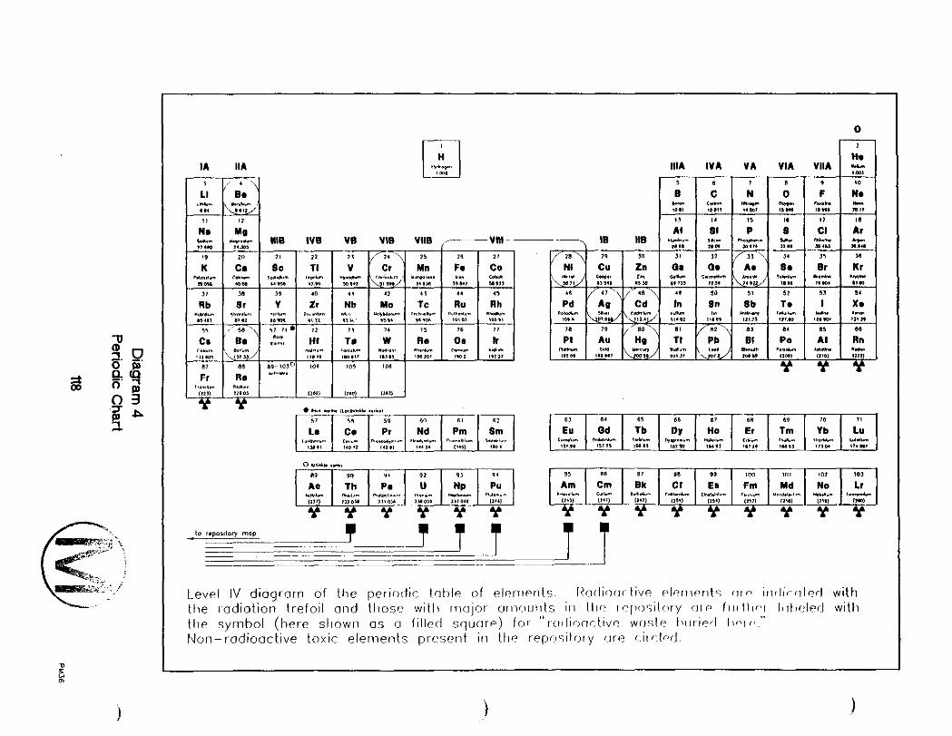
I A IIA
m
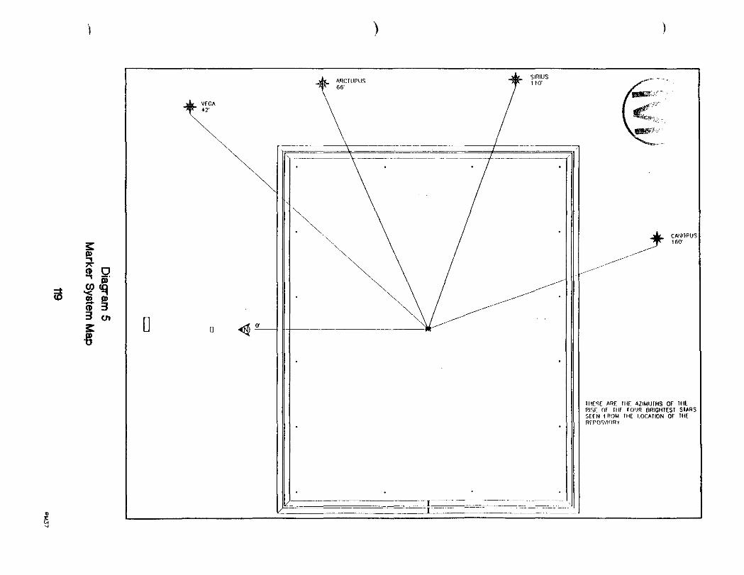


FOR ILLUSTRATION ONLY

,' '02.90 METERS (9.51 FT.) /'
m3.c METEPS (9.84 F.) // NC- TO SCALE
Diagram 8 Longitude and Latitude of Disposal Shes Relative to WiPP at '0'
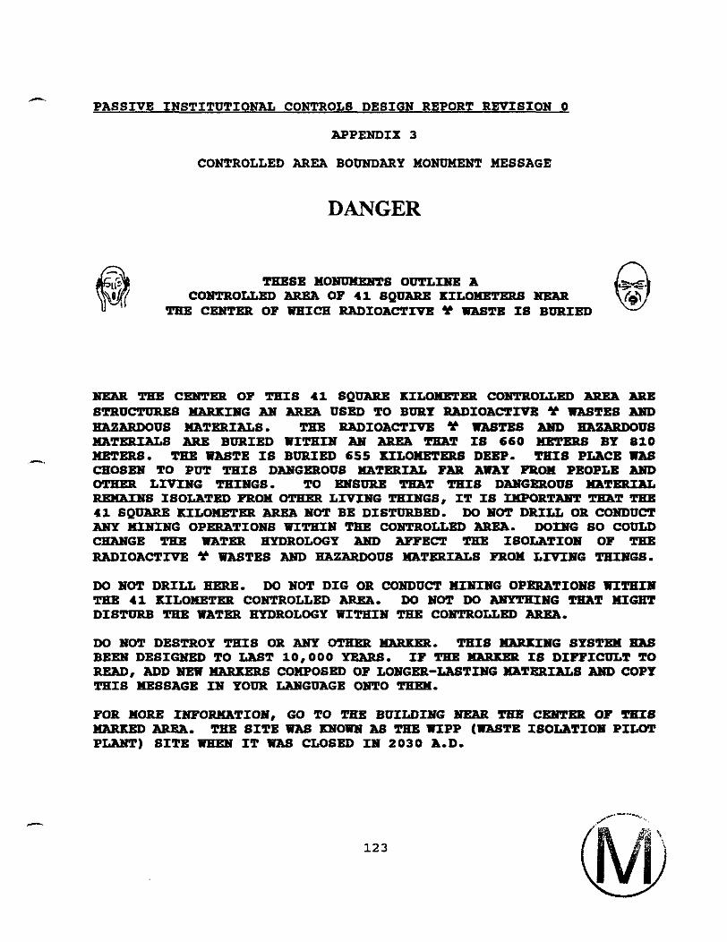
A
PASSIVE INSTITUTIONAL CONTROLS DESIGN REPORT REVISION 0
APPENDIX 3
CONTROLLED AREA BOUNDARY MONTJMENT MESSAGE
DANGER
THESE 110-8 OVTLIlYE A COXTROUgD llREA OP 41 SQUARE KILOMETERS
THE CEHTER OF WHICH RADIOACTIVE Y WASTE IS BURIED
HEAR THE CEHTKR OP THIS 41 SQUARE KILOMETEB CONEROLLED AREA ARB STRUCTURES MARKING AH AREA USED TO BURY RADIOACTIVB 9 WASTES AND -US HXTXUIALS. THE RADIOACTIVE Y WASTES AND EWBaDOUS MATERIALS ARB BURIED WITHIN AH AREA TEAT IS 660 =EBB BY 810
-, METERS. THE WASTE IS BURIED 655 KILOMETERS DEEP. THIS PLACE WAS CHOSEW TO PUT THIS DAHGEROUS MATERIAL PAR AWAY FROM PEOPLE AND OTHEa LIVING THINGS. TO KUSURE TEAT THIS DAMGEROUS MATERIAL REHAINS ISOLATED FROM OTHER LIVING THINGS, IT IS IKPORT- m T TEE 41 SQUARE KILOlIETXU AREA NOT BE DISTURBED. DO lYOT DRILL OR CONDUCT ANY HIMHG OPERATIONS WITHIN TEE CONEROLLED AREA. DOmG 80 COULD CHANGE THE WATER HYDROLOGY AHD APPECT THE ISOLATION OF THE RADIOACTIVE 9 WASTES AND HAZARDOUS HATERIALS FROM LIVIlVG THIHGS.
DO NOT DRILL HERE. DO NOT DIG OR CONDUCT M I m G OPERATIONS UXTEIlP THE 41 KILOMETXU COHTROLLED AREA. DO NOT DO AU'YTXIISG TEAT MIGlIT DISTURB TEE WATER HYDROLOGY WITHIN THE COXTROLLED AREA.
DO NOT DESTROY THIS OR ANY oTHEa MARKXR. THIS MARKING SYSTEM HBS BEKU DESIGNED TO LAST 10,000 YEARS. IP THE MARKER IS DIFFICULT TO READ, ADD HEW MARKERS COMPOSED OF LONGER-LASTIISG HATERIALS AND COPY THIS MESSAGE IN YOUR LAUGUAGE ONTO TEEM.
FOR MORE IIUPORKATIOH, GO TO TEE BUILDING HEAR TEE CCKlPTKP OP TgIS HARKED AREA. TEE SITE WAS QSOWH AS THE UIPP (WASTE ISOLATION PILOT P-) SITE IT U?S CLOSED IN 2030 A.D.
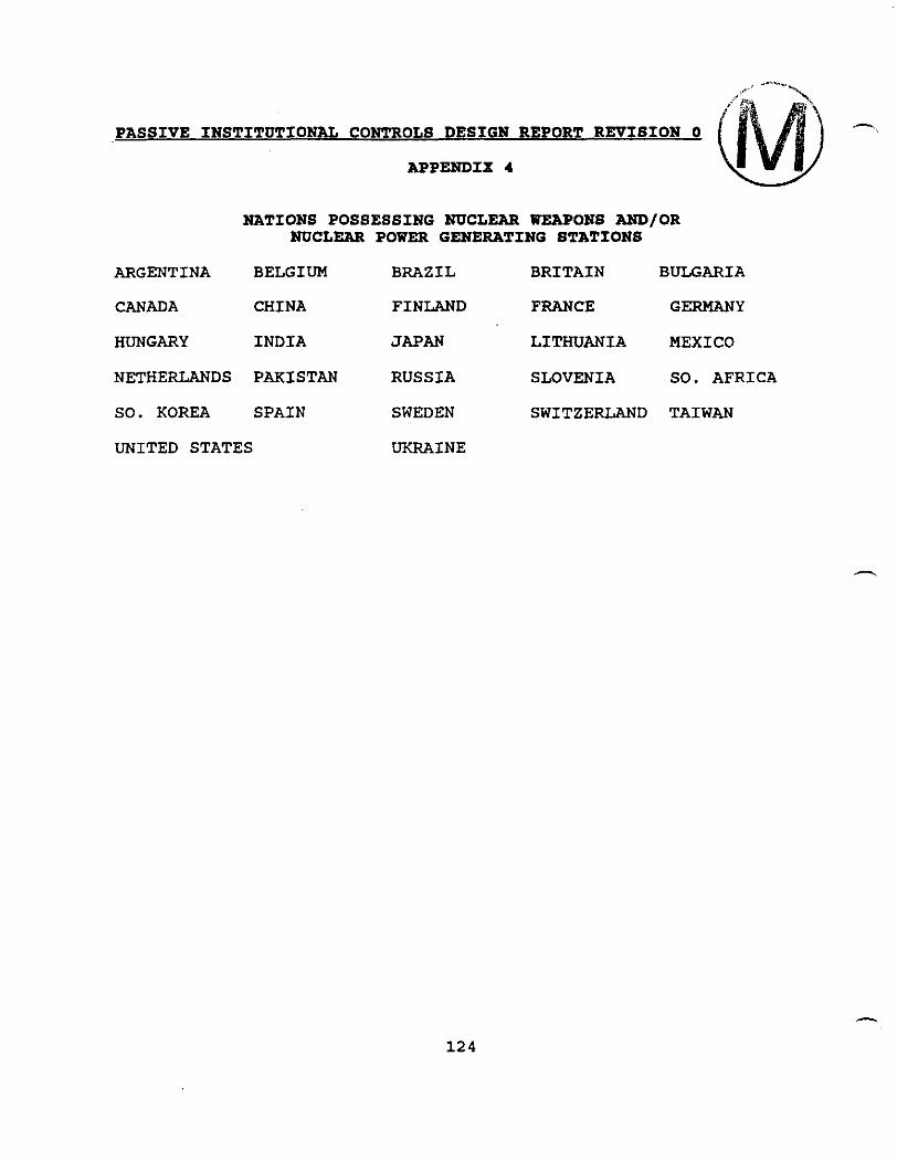
PASSIVE INSTITUTIONAL CONTROLS DESIGN REPORT REVISION 0 h
APPENDIX 4
NATIONS POSSESSING NUCLEAR WEAPONS AND/OR NUCLEAR POWER GENERATING STATIONS
ARGENTINA BELGIUM BRAZIL BRITAIN BULGARIA
CANADA CHINA FINLAND FRANCE GERMANY
HUNGARY INDIA JAPAN LITHUANIA MEXICO
NETHERLANDS PAKISTAN RUSSIA SLOVENIA SO. AFRICA
SO. KOREA SPAIN SWEDEN SWITZERLAND TAIWAN
UNITED STATES UKRAINE

- PASSIVE INSTITUTIONAL CONTROLS DESIGN REPORT REVISION 0
APPENDIX 5
WORLD NATIONS WHICH POSSESS NATURAL GAS AND/OR PETROLELW RESODRCES AND
NOT INCLUDED IN APPENDIX 5 NATIONS LISTING
AFGHANISTAN ALBANIA ALGERIA AUSTRALIA AUSTRIA BAHRAIN BARBADOS BELARUS BENIN BURNEI BURMA CAMBODIA CHAD CHILE COLOMBIA COTE D'IVOIRE CZECH REPUBLIC DENMARK EQUATORIAL GUINEA EGYPT ETHIOPIA GHANA GREECE GUATEMALA IRAN IRAQ IRELAND ITALY JORDAN KAZAKHSTAN KYRGYZSTAN LIBYA MADAGASCAR MONGOLIA MOROCCO MOZAMBIQUE NEW ZEALAND NIGER NIGERIA OMAN PAPUA NEW GUINEA PHILIPPINES POLAND QATAR
A RWANDA SAUDIA ARABIA SENEGAL SOMALIA SUDAN SURINAME TAJIKISTAN TANZANIA THAILAND TRINIDAD AND TOBAGO TURKEY TURKMENISTAN UNITED ARAB EMIRATES YEMEN VENEZUELA YUGOSLAVIA ZAIRE
ANGOLA BANGLADESH BOLIVIA CAMEROON CONGO ECUADOR GABON INDONESIA ISRAEL KUWAIT MALAYSIA NAMIBIA NORWAY PERU ROMANIA SLOVAKIA SYRIA TUNISIA UKRAINE VIETNAM
PASSIVE INSTITUTIONAL CONTROLS DESIGN REPORT REPISION 0
TRANSLATION OF THE ENGLISH VERSION OF THE LEVEL 11, 111, AND IV MESSAGES INTO ARABIC, CHINESE, FRENCH, SPANISH, RUSSIAN, AND NAVAJO WILL BE COMPLETED DURING THE FINAL DESIGN PEASE AND SUBJECTED TO TESTING AMONG INDIGENOUS PEOPLE PRIOR TO FINALIZATION.