
4 Project-wide design principles Landscape Principles · 30 Project-wide design principles ......
16
30 Project-wide design principles // Transmission Gully Project // Urban and Landscape Design Framework // August 2011 4 Project-wide design principles 4.1 Urban and landscape design concept The overall concept underpinning the urban and landscape design of the Transmission Gully Project is to: Create an ‘open sky’ highway with expansive views of the surrounding landscape unobstructed by structures - a result of the main alignment sitting above all interchanges and local roads; Emphasise the linear character of the highway as a landscape ‘fault line’ – a reflection of underlying geomorphology and reinforcement of the road as a continuous landscape element and experience in its own right; Emphasise the existing landscape patterns perpendicular to the highway – a reflection of existing natural landscape patterns and sense of place, and reinforcement of the road as providing connection with the broader landscape; Emphasise the interchange with SH58 with a landscape treatment incorporating new wetlands and tree planting; and Celebrate the threshold between the hill country and the urban area at the southern end of the route through sculptured earth form and a gateway underpass design. The concept is supported by a number of design principles which are presented in the following sections. Landscape Principles Restore vegetation in a bold manner using limited species palettes and broad spatial patterns in order to fit the scale of the landscape; Design re-vegetation to be contiguous with vegetation patterns beyond the corridor; Emphasise the underlying topography, for instance by establishing riparian vegetation along streams and retaining intervening spurs in pasture; and Reinforce the experience of the landscape traversed by road users: - Emphasise the contrasting character areas through vegetation selection and response to the topography and adjacent land uses; - Create a pattern of enclosure or openness that reflects the adjacent landscape character; - Highlight local materials such as greywacke rock and native vegetation; - Ensure that the opportunities to provide key landscape views for road users are not lost by poor detailing; and - Maintain where practicable adjacent landscape patterns across the highway. 4.2 Landscape design principles Highway Principles Design the highway and associated elements to emphasise the highway’s linear character, horizontal lines and sharp edges; Minimise the overall construction and final footprint of the road; Select a coherent suite of highway furniture, using a common language and consistent scale, form, materials, colours and spatial arrangements; and Minimise visual clutter of highway furniture elements: - Limit the variety for each type of element (for instance by limiting types of safety barrier); - Limit the materials and colours for the range of elements; - Use recessive colours; - Avoid ornamentation; - Configure elements to a consistent spatial pattern (for instance the location of sign posts relative to the carriageway); and - Use earth contouring and clear zones where practicable in order to reduce the extent of barriers. Connection between Highway and Landscape Limit the ‘in-between’ space between the highway and adjacent landscape, and strengthen the extent to which the highway sits within the landscape; Create a hard / sharp edge between the shoulder and adjacent vegetation, bringing the existing and re-instated vegetation right up to the road where practicable (i.e. avoiding an in-between strip of ground) and reducing the need for herbicide maintenance; Extend adjacent land use and vegetation patterns as close to the highway shoulder as possible consistent with safety requirements; and Continue underlying landscape patterns on both sides of the highway so that the highway is not a boundary between different landscape patterns. -
-
Upload
hoanghuong -
Category
Documents
-
view
215 -
download
0
Transcript of 4 Project-wide design principles Landscape Principles · 30 Project-wide design principles ......
30 Project-wide design principles // Transmission Gully Project // Urban and Landscape Design Framework // August 2011
4 Project-wide design principles
4.1 Urban and landscape design concept
The overall concept underpinning the urban and
landscape design of the Transmission Gully Project
is to:
� Create an ‘open sky’ highway with expansive views of the surrounding landscape unobstructed by structures - a result of the main alignment sitting above all interchanges and local roads;
� Emphasise the linear character of the highway as a landscape ‘fault line’ – a reflection of underlying geomorphology and reinforcement of the road as a continuous landscape element and experience in its own right;
� Emphasise the existing landscape patterns perpendicular to the highway – a reflection of existing natural landscape patterns and sense of place, and reinforcement of the road as providing connection with the broader landscape;
� Emphasise the interchange with SH58 with a landscape treatment incorporating new wetlands and tree planting; and
� Celebrate the threshold between the hill country and the urban area at the southern end of the route through sculptured earth form and a gateway underpass design.
The concept is supported by a number of design
principles which are presented in the following
sections.
Landscape Principles
� Restore vegetation in a bold manner using limited
species palettes and broad spatial patterns in order to
fit the scale of the landscape;
� Design re-vegetation to be contiguous with
vegetation patterns beyond the corridor;
� Emphasise the underlying topography, for instance
by establishing riparian vegetation along streams and
retaining intervening spurs in pasture; and
� Reinforce the experience of the landscape traversed
by road users:
- Emphasise the contrasting character areas
through vegetation selection and response to the
topography and adjacent land uses;
- Create a pattern of enclosure or openness that
reflects the adjacent landscape character;
- Highlight local materials such as greywacke rock
and native vegetation;
- Ensure that the opportunities to provide key
landscape views for road users are not lost by poor
detailing; and
- Maintain where practicable adjacent landscape
patterns across the highway.
4.2 Landscape design principles
Highway Principles
� Design the highway and associated elements to
emphasise the highway’s linear character, horizontal
lines and sharp edges;
� Minimise the overall construction and final footprint
of the road;
� Select a coherent suite of highway furniture, using
a common language and consistent scale, form,
materials, colours and spatial arrangements; and
� Minimise visual clutter of highway furniture elements:
- Limit the variety for each type of element (for
instance by limiting types of safety barrier);
- Limit the materials and colours for the range of
elements;
- Use recessive colours;
- Avoid ornamentation;
- Configure elements to a consistent spatial pattern
(for instance the location of sign posts relative to
the carriageway); and
- Use earth contouring and clear zones where
practicable in order to reduce the extent of
barriers.
Connection between Highway and Landscape
� Limit the ‘in-between’ space between the highway
and adjacent landscape, and strengthen the extent to
which the highway sits within the landscape;
� Create a hard / sharp edge between the shoulder
and adjacent vegetation, bringing the existing
and re-instated vegetation right up to the road
where practicable (i.e. avoiding an in-between strip
of ground) and reducing the need for herbicide
maintenance;
� Extend adjacent land use and vegetation patterns as
close to the highway shoulder as possible consistent
with safety requirements; and
� Continue underlying landscape patterns on both
sides of the highway so that the highway is not a
boundary between different landscape patterns.
-
31Transmission Gully Project // Urban and Landscape Design Framework // August 2011 // Project-wide design principles
4.3 Earthworks design principles
General principles
The design of earthworks should:
� Minimise the overall footprint of the road;
� Minimise the visual effects of earthworks;
� Avoid or minimise encroachment into water courses
and bodies and areas of indigenous vegetation; and
� Seek to respond to, and reinforce the adjacent natural
landscape and landform taking into consideration soil
and rock types, fault lines, route security and existing
services.
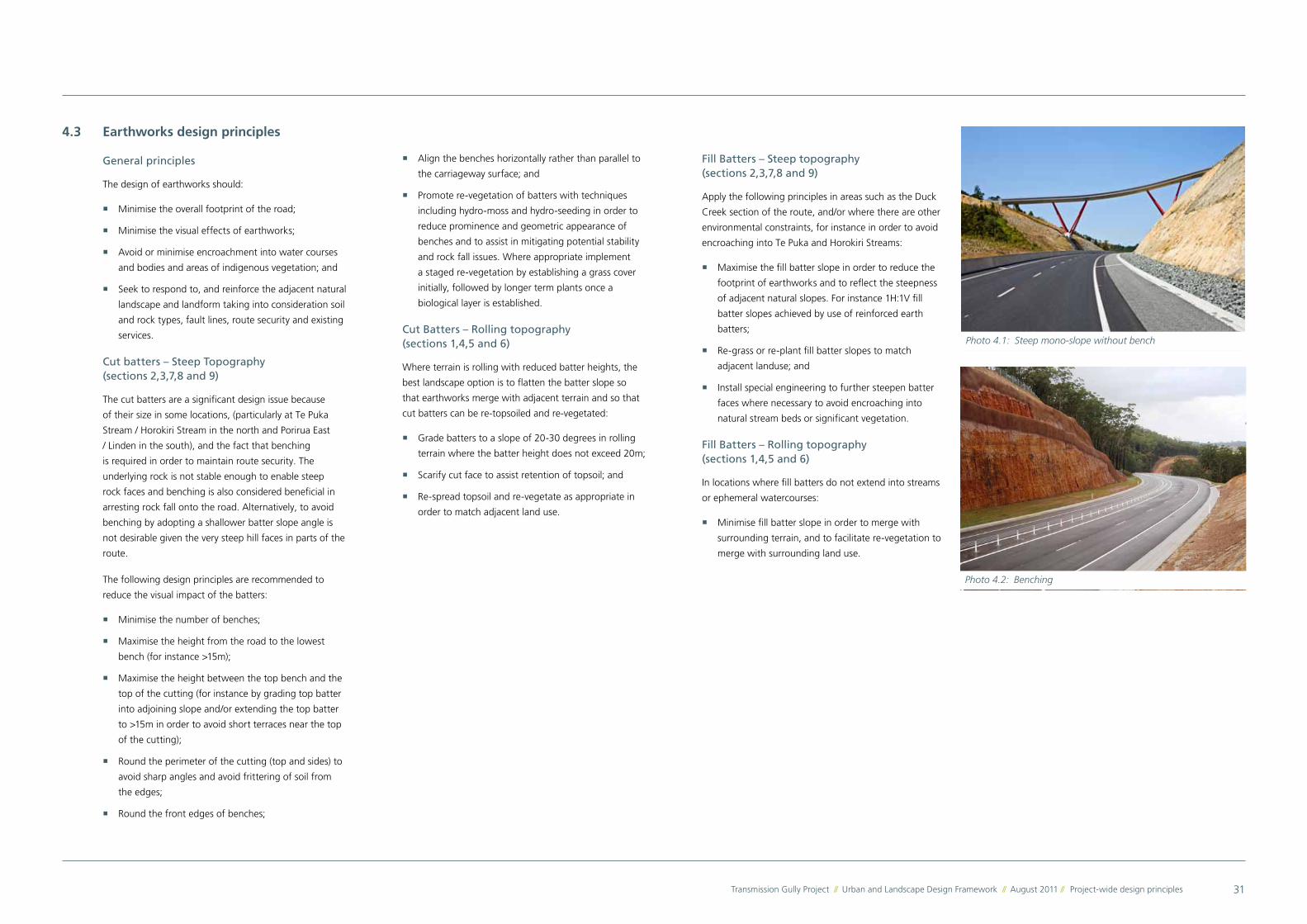
Cut batters – Steep Topography (sections 2,3,7,8 and 9)
The cut batters are a significant design issue because
of their size in some locations, (particularly at Te Puka
Stream / Horokiri Stream in the north and Porirua East
/ Linden in the south), and the fact that benching
is required in order to maintain route security. The
underlying rock is not stable enough to enable steep
rock faces and benching is also considered beneficial in
arresting rock fall onto the road. Alternatively, to avoid
benching by adopting a shallower batter slope angle is
not desirable given the very steep hill faces in parts of the
route.
The following design principles are recommended to
reduce the visual impact of the batters:
� Minimise the number of benches;
� Maximise the height from the road to the lowest
bench (for instance >15m);
� Maximise the height between the top bench and the
top of the cutting (for instance by grading top batter
into adjoining slope and/or extending the top batter
to >15m in order to avoid short terraces near the top
of the cutting);
� Round the perimeter of the cutting (top and sides) to
avoid sharp angles and avoid frittering of soil from
the edges;
� Round the front edges of benches;
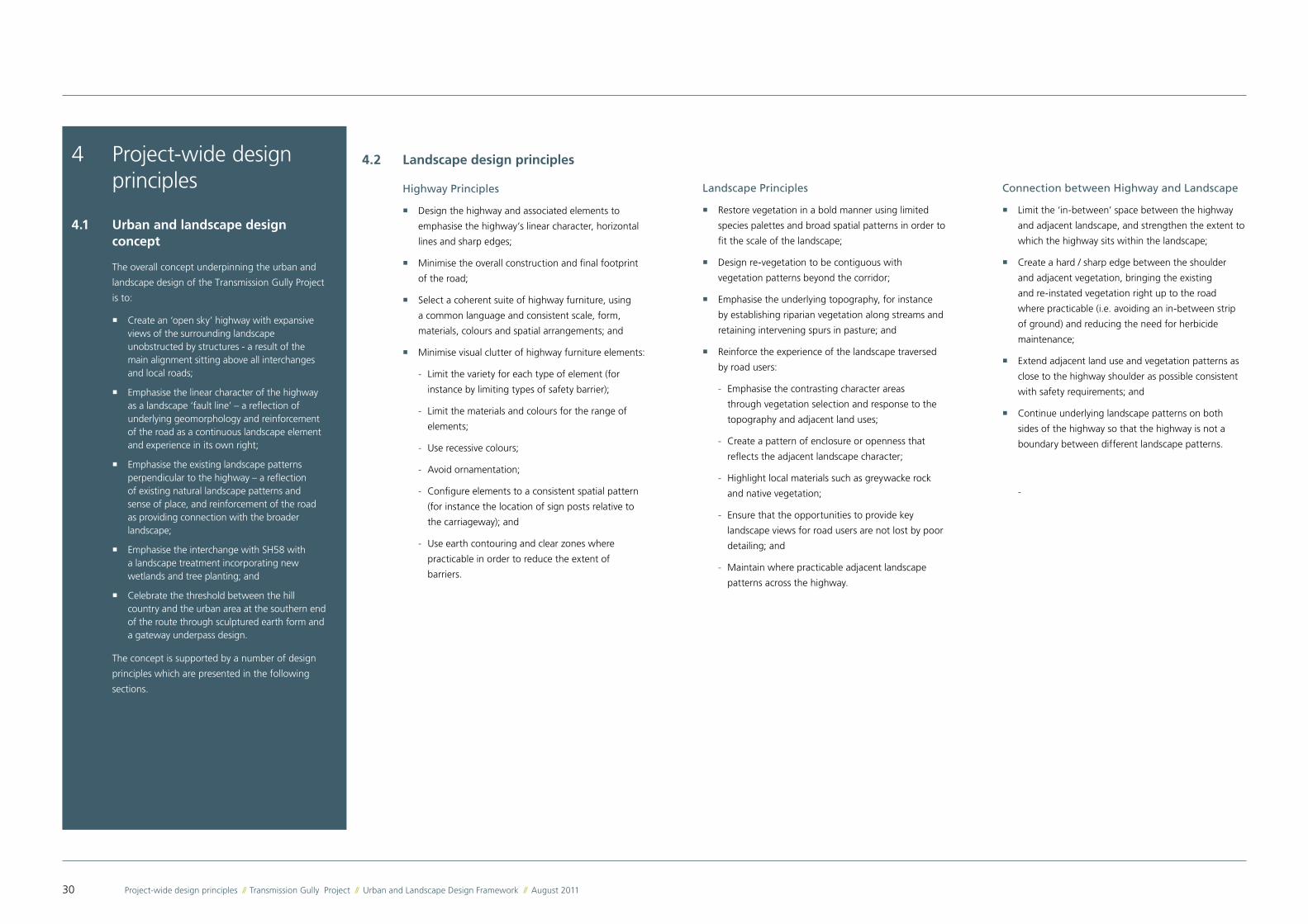
Fill Batters – Steep topography (sections 2,3,7,8 and 9)
Apply the following principles in areas such as the Duck
Creek section of the route, and/or where there are other
environmental constraints, for instance in order to avoid
encroaching into Te Puka and Horokiri Streams:
� Maximise the fill batter slope in order to reduce the
footprint of earthworks and to reflect the steepness
of adjacent natural slopes. For instance 1H:1V fill
batter slopes achieved by use of reinforced earth
batters;
� Re-grass or re-plant fill batter slopes to match
adjacent landuse; and
� Install special engineering to further steepen batter
faces where necessary to avoid encroaching into
natural stream beds or significant vegetation.
Fill Batters – Rolling topography (sections 1,4,5 and 6)
In locations where fill batters do not extend into streams
or ephemeral watercourses:
� Minimise fill batter slope in order to merge with
surrounding terrain, and to facilitate re-vegetation to
merge with surrounding land use.
Photo 4.1: Steep mono-slope without bench
� Align the benches horizontally rather than parallel to
the carriageway surface; and
� Promote re-vegetation of batters with techniques
including hydro-moss and hydro-seeding in order to
reduce prominence and geometric appearance of
benches and to assist in mitigating potential stability
and rock fall issues. Where appropriate implement
a staged re-vegetation by establishing a grass cover
initially, followed by longer term plants once a
biological layer is established.
Cut Batters – Rolling topography (sections 1,4,5 and 6)
Where terrain is rolling with reduced batter heights, the
best landscape option is to flatten the batter slope so
that earthworks merge with adjacent terrain and so that
cut batters can be re-topsoiled and re-vegetated:
� Grade batters to a slope of 20-30 degrees in rolling
terrain where the batter height does not exceed 20m;
� Scarify cut face to assist retention of topsoil; and
� Re-spread topsoil and re-vegetate as appropriate in
order to match adjacent land use.
Photo 4.2: Benching
32 Project-wide design principles // Transmission Gully Project // Urban and Landscape Design Framework // August 2011
4.4 Structures design principles
4.4.1 Bridges
Bridge designs conform with the Structure Design
Philosophy which is influenced by a number of key
factors including:
• Cost efficiency with consideration for whole of
life cost: Wherever possible bridges have been
avoided in preference to embankments due to the
disproportionate cost of structures when compared to
earthworks;
• Regional network security in the event of a large
earthquake: Highly redundant bridge forms and
seismically proven MSE retaining walls and 45 degree
reinforced soil slopes have been selected for the
Project;
• Environmental and social considerations: In some
locations bridges have been selected instead of
culverts to minimise the structure’s footprint,
sediment movement and flow velocity and to
maintain fish passage. Aesthetics considerations have
informed bridge designs. The number of construction
tracks has been minimised through careful choice of
structural form;
• Durability and maintenance: High durability, long
lasting coating systems (up to 40 years to first
maintenance) have been assumed in the costing
of steel bridges. Concrete elements in bridges and
retaining walls will be designed for a 100 year design
life and will require little if any maintenance; and
• Aesthetics and visual effects: Clear structural lines
and unadorned, neat concrete finishes have been
selected. Bridges with fewer larger piers have been
selected over solutions with many smaller elements to
minimise the visual and physical effect of the bridges
on the landscape. Superstructures which provide
elegant uncluttered solutions have been selected
in highly visible or landscape sensitive locations. A
consistent treatment of abutment wrapped with MSE
walls is the preferred approach to provide continuity
of design through the Project.
Spoil Disposal Sites
� Locate spoil disposal on areas near watersheds such
as broad spur summits, plateaux and natural benches,
and shallow basins at the heads of catchments. Avoid
locating spoil disposal sites in stream or ephemeral
watercourse valleys;
� Locate spoil disposal preferably on areas of pasture
so as to avoid areas of native bush or other significant
vegetation as much as possible;
� Maintain low profile by restricting spoil disposal
to a maximum 3m depth with rounded edges. It
is preferable to occupy a larger footprint with low
profile landforms on less sensitive sites than to create
deep disposal sites in sensitive areas; and
� Strip, stockpile and re-spread topsoil over completed
spoil disposal sites and re-plant with species that
reflect original vegetation patterns and merge with
adjacent land-use.
Rock Fall Protection
The primary focus is to achieve passive rock fall
protection through cut face configuration and vegetation
in the longer term. There will be instances along the
Project route where localised rock fall structures will be
required to ensure safety and route security issues are
addressed.
� In the first instance draped netting should be used
to address rock fall, allowing the surface profile
of the cut face to be retained and becoming
visually recessive over time through the inclusion of
vegetation;
� Where rock fall fences are required at road level they
should be:
- incorporated into any safety barrier;
- located on the same alignment as other furniture
such as light poles or signs;
- constructed of similar materials to adjacent road
elements; and
� Where rock fall fences are required on benches they
should be constructed out of ‘light’ materials and
set back from the front edge of the bench to reduce
visual prominence. The focus should be on visual
continuity and rock fall fences being part of a suite
of road side furniture that promote visual continuity
along the route.
Slope Stabilisation
Given variations in geology along the length of the
Project route there may be instances where localised
slope stabilisation measures are required. Such measures
may include (but not be limited to) reinforced soil
embankments, rock bolts and anchors; soil nails;
shotcrete; dental concrete and mesh.
� Limit the use of these measures and ensure they are
as visually recessive as possible;
� Avoid a high number of interventions creating visual
anomalies along the route. Large sections of visually
prominent stabilisation structure should also be
avoided if alternatives that satisfy both structural and
visual parameters are practicable;
� The use of shotcrete should be avoided if other
practicable alternatives exist. Where shotcrete is
required then methods such as pigmentation and
surface treatment should seek to mimic adjacent
natural material;
� Where mesh, wire baskets, hydroseed and other
materials can be used to provide medium for plant
growth on stabilised slopes, they should be preferred
over concrete finishes.
33Transmission Gully Project // Urban and Landscape Design Framework // August 2011 // Project-wide design principles
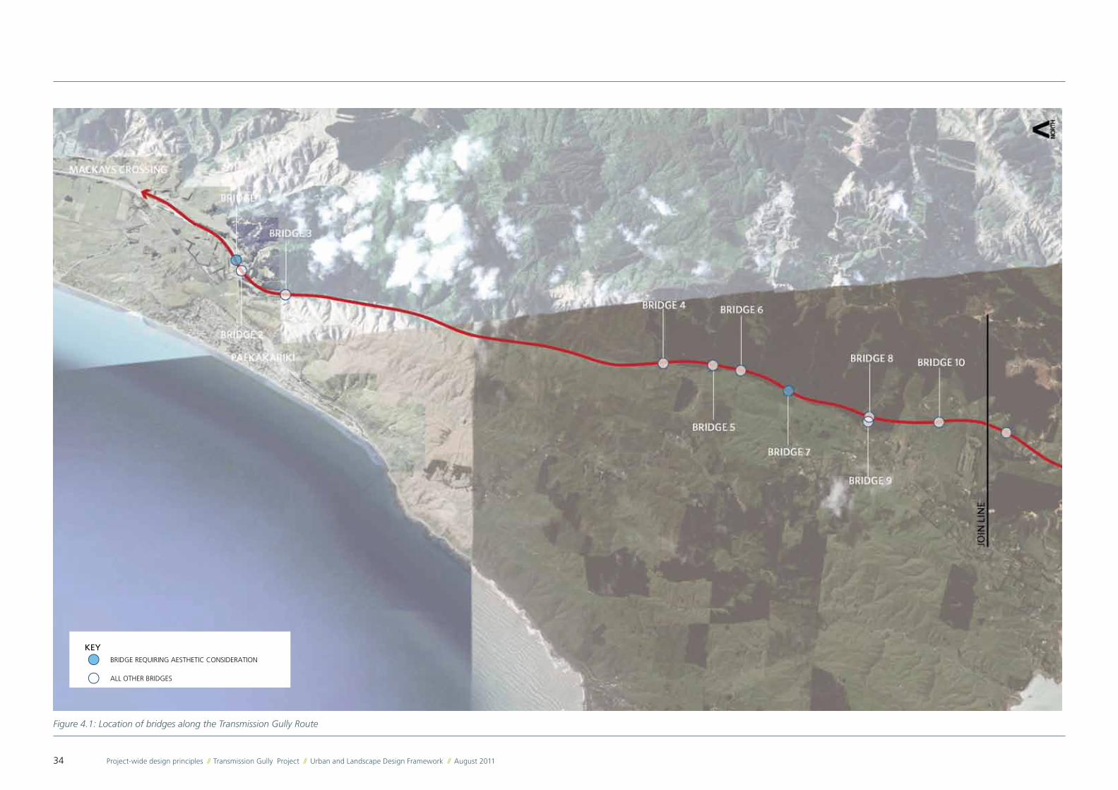
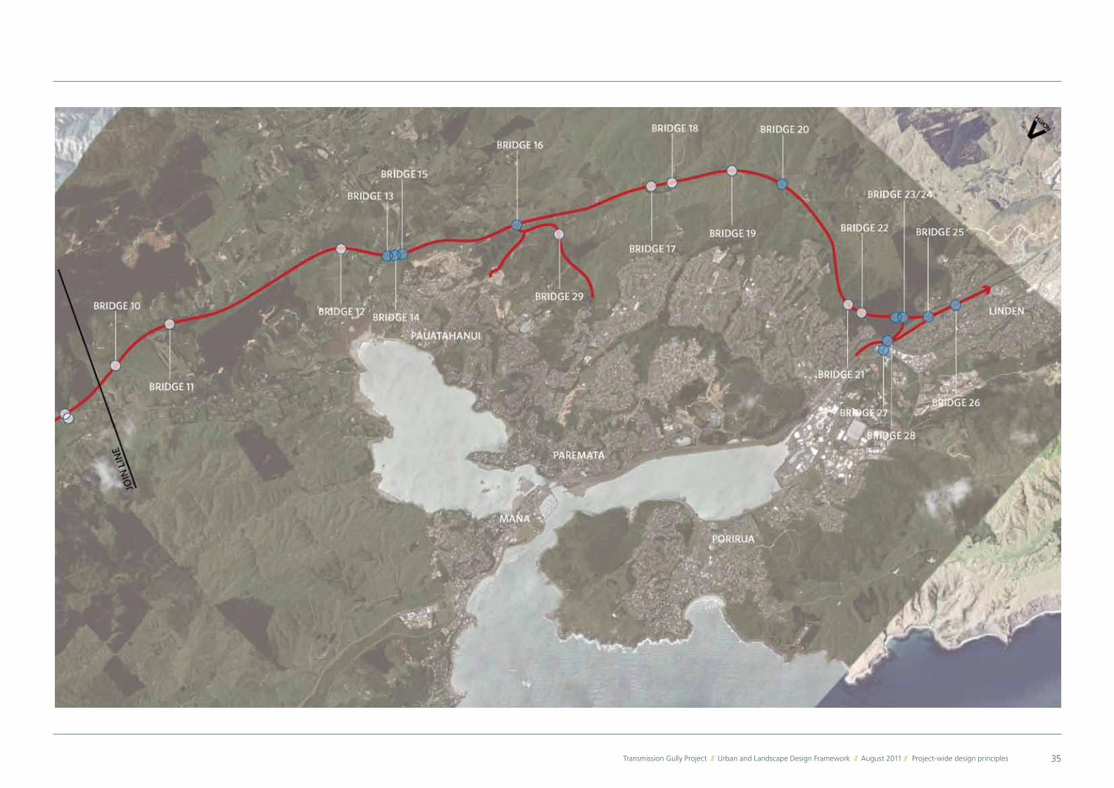
All the bridges within this Project were assessed early on
to determine the appropriate level of aesthetic treatment
required, if any. The bridges were classified based on
their visibility for road users and the local community.
Those bridges which will be visible from the surrounding
communities, Regional Park tracks or the highway itself
are subject to aesthetic considerations as outlined in this
Framework. The considerations are of two types:
� The bridges which will be visible from a long distance
are subject to design principles relating to their
overall form.
� The bridges which will be visible at close range by
pedestrians, cyclists, residents and road users are
subject to design principles relating to their detailed
design and finishes.
The bridges which are subject to aesthetic considerations
are highlighed on Figure 4.2.
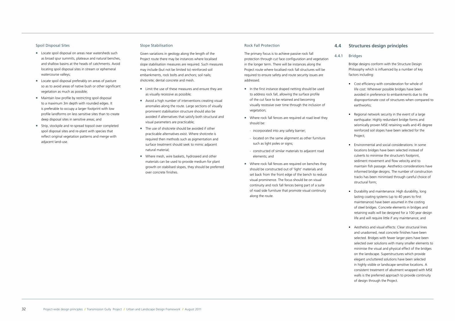
Photo 4.3: Feature lighting for gateway location
Photo 4.4: Elegant profile: Twin haunched girder bridges
Photo 4.5: Bridge barrier extends down to conceal girder
� Design bridge barriers with a skirt to conceal the
full depth of the deck (girder and rc slab deck) and
drainage pipes;
� Where the road corridor is constrained, closed
(vertical) abutments should be carefully designed
and detailed to present a high quality finished
appearance. Along Collins Avenue, where the
abutments will be seen at close range by pedestrians,
cyclists and motorists, their design should incorporate
finer grain details, textures, artwork or colour
scheme;
� Structures that eliminate the need for cap beams
(headstocks) and enable simple, elegant girder to
pier connection are preferred. Where cap beams are
required, minimise length of cap beam beyond last
girder;
� Where practicable, the preference is to drop the pile
to column connection to be fully below ground;
� Where a bridge crosses over a local road or
pedestrian / cycle path, to provide a light well in the
median if practicable;
� Any bridge lighting and drainage should be
integrated with the structure, leaving the external
surfaces of the bridge free of drainage pipes or
services. Lighting design and selection should
incorporate protection against vandalism;
� Locate highway lighting columns to respect the
visual rhythm of the bridge. This can be achieved by
aligning the columns with bridge piers or laying them
out symmetrically on either side of the piers;
� Select durable materials and finishes that do not
significantly degrade in appearance over time; and
� If required, a clear, matte anti-graffiti coating should
be applied to the full extent of piers, MSE walls and
barriers at the bridge construction phase to prevent
patchy application and appearance at later stages.
More detailed bridge design principles are listed below.
Where bridges are visible from surrounding communities,
regional parks or the highway itself, the following design
principles apply:
� Bridges should complement their context. This means
considering factors such as, but not limited to, the
topography, location of watercourses, the rural
or urban setting, the bridge visibility, presence of
valuable vegetation or ecology features, proximity
to houses or open spaces and the presence of
pedestrian or cycle paths across or in the vicinity of
the bridge;
� Design bridges to be recognisable as part of the
Transmission Gully Project ‘family’, with individual
variations reflecting the requirements of their specific
setting;
� The relative proportion of structural elements should
be carefully considered to minimise the bridge profile,
achieve balance, and create a simple, elegant whole.
Seek to equalise or balance spans;
� A play of light and shadow on a bridge can reduce
the apparent mass and bulk of the structure and
balance its vertical and horizontal proportions.
Sloping all or part of the outer face of the side barrier
inwards to catch the sunlight, extending the barrier
down past the deck and recessing beams to create a
shadow line, will reinforce the horizontal lines of the
bridge;
� Barriers depth should be carefully proportioned in
relation to the deck and superstructure. Barriers
should be extended well past abutments to anchor
the bridge in the landscape. Sloping the top of the
barrier inwards towards the deck will minimise water
staining on the outer face of the barrier. Barriers
should have minimum embellishments, with any
surface treatment used only to reinforce the clean
lines of the bridge;
34 Project-wide design principles // Transmission Gully Project // Urban and Landscape Design Framework // August 2011
Figure 4.1: Location of bridges along the Transmission Gully Route
KEYBRIDGE REQUIRING AESTHETIC CONSIDERATION
ALL OTHER BRIDGES
35Transmission Gully Project // Urban and Landscape Design Framework // August 2011 // Project-wide design principles
36 Project-wide design principles // Transmission Gully Project // Urban and Landscape Design Framework // August 2011
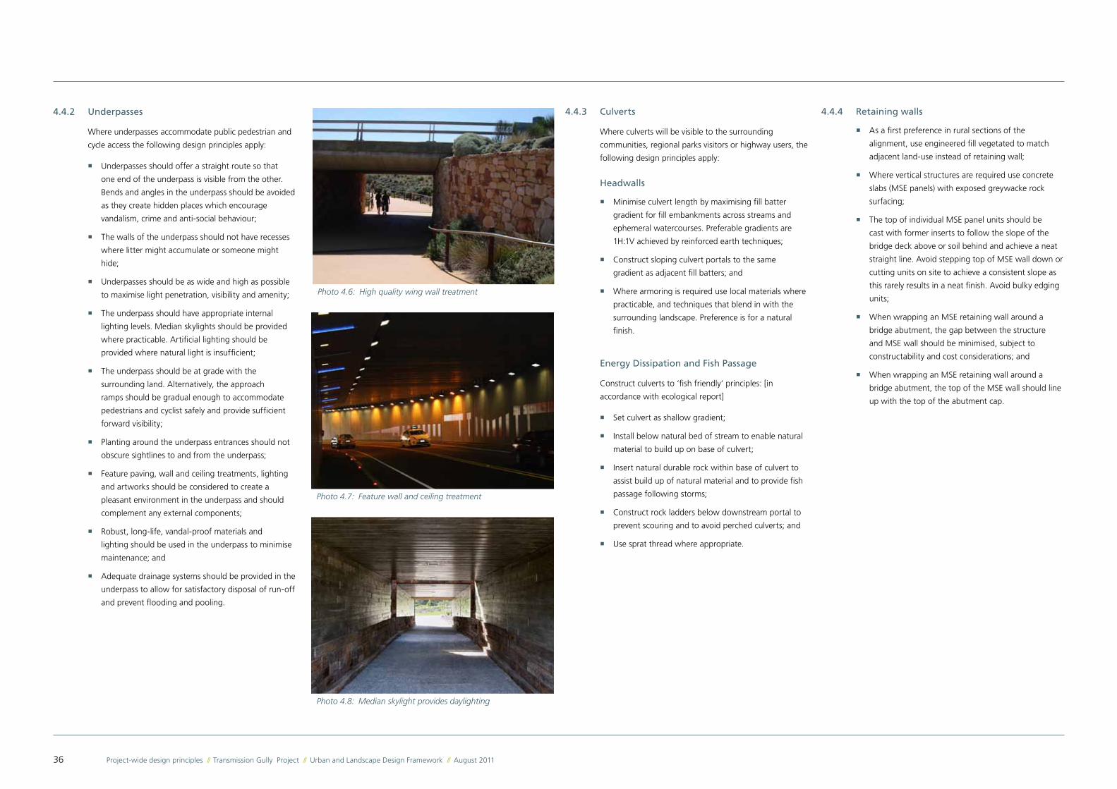
4.4.2 Underpasses
Where underpasses accommodate public pedestrian and
cycle access the following design principles apply:
� Underpasses should offer a straight route so that
one end of the underpass is visible from the other.
Bends and angles in the underpass should be avoided
as they create hidden places which encourage
vandalism, crime and anti-social behaviour;
� The walls of the underpass should not have recesses
where litter might accumulate or someone might
hide;
� Underpasses should be as wide and high as possible
to maximise light penetration, visibility and amenity;
� The underpass should have appropriate internal
lighting levels. Median skylights should be provided
where practicable. Artificial lighting should be
provided where natural light is insufficient;
� The underpass should be at grade with the
surrounding land. Alternatively, the approach
ramps should be gradual enough to accommodate
pedestrians and cyclist safely and provide sufficient
forward visibility;
� Planting around the underpass entrances should not
obscure sightlines to and from the underpass;
� Feature paving, wall and ceiling treatments, lighting
and artworks should be considered to create a
pleasant environment in the underpass and should
complement any external components;
� Robust, long-life, vandal-proof materials and
lighting should be used in the underpass to minimise
maintenance; and
� Adequate drainage systems should be provided in the
underpass to allow for satisfactory disposal of run-off
and prevent flooding and pooling.
4.4.4 Retaining walls
� As a first preference in rural sections of the
alignment, use engineered fill vegetated to match
adjacent land-use instead of retaining wall;
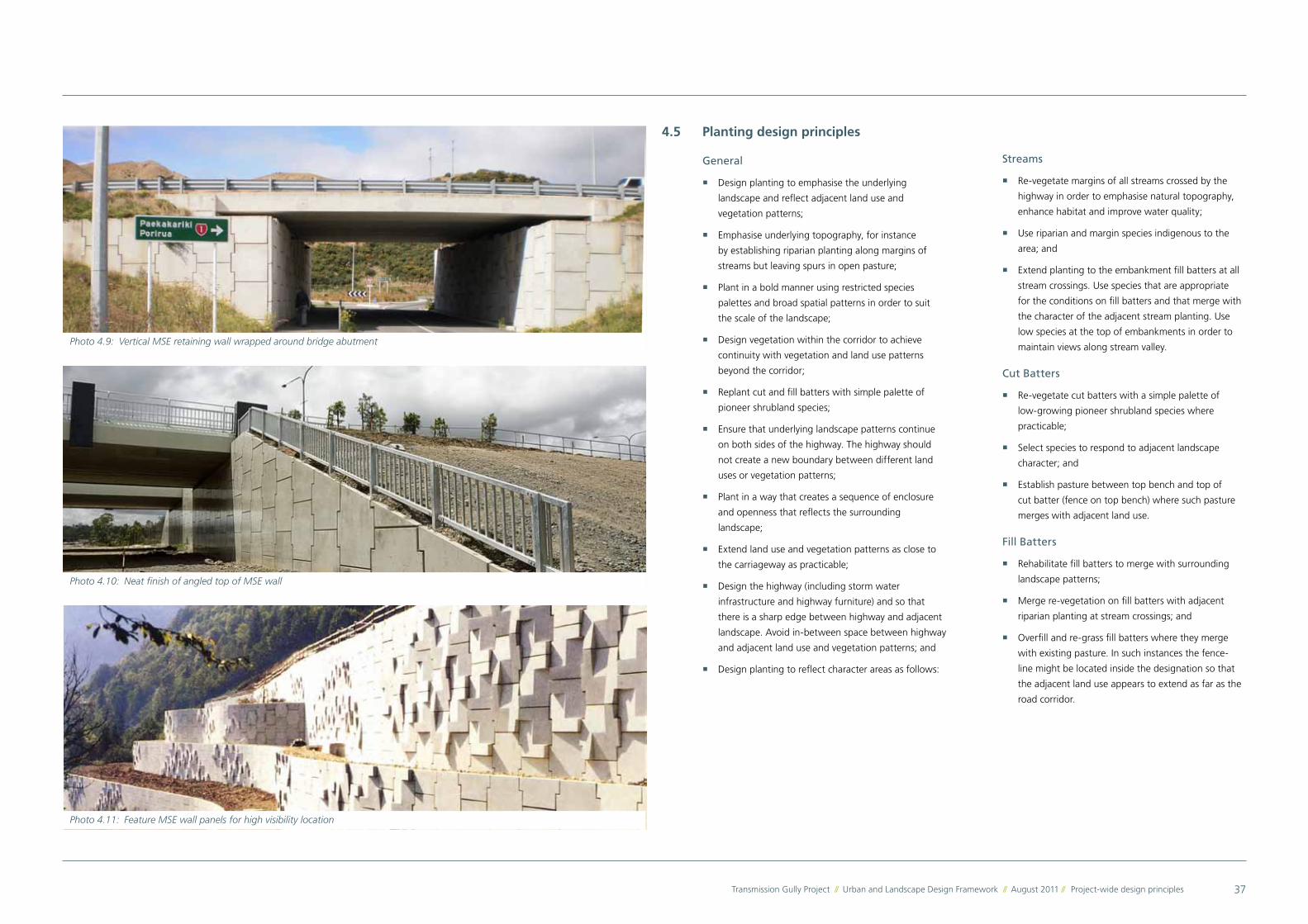
� Where vertical structures are required use concrete
slabs (MSE panels) with exposed greywacke rock
surfacing;
� The top of individual MSE panel units should be
cast with former inserts to follow the slope of the
bridge deck above or soil behind and achieve a neat
straight line. Avoid stepping top of MSE wall down or
cutting units on site to achieve a consistent slope as
this rarely results in a neat finish. Avoid bulky edging
units;
� When wrapping an MSE retaining wall around a
bridge abutment, the gap between the structure
and MSE wall should be minimised, subject to
constructability and cost considerations; and
� When wrapping an MSE retaining wall around a
bridge abutment, the top of the MSE wall should line
up with the top of the abutment cap.
Photo 4.6: High quality wing wall treatment
Photo 4.7: Feature wall and ceiling treatment
Photo 4.8: Median skylight provides daylighting
4.4.3 Culverts
Where culverts will be visible to the surrounding
communities, regional parks visitors or highway users, the
following design principles apply:
Headwalls
� Minimise culvert length by maximising fill batter
gradient for fill embankments across streams and
ephemeral watercourses. Preferable gradients are
1H:1V achieved by reinforced earth techniques;
� Construct sloping culvert portals to the same
gradient as adjacent fill batters; and
� Where armoring is required use local materials where
practicable, and techniques that blend in with the
surrounding landscape. Preference is for a natural
finish.
Energy Dissipation and Fish Passage
Construct culverts to ‘fish friendly’ principles: [in
accordance with ecological report]
� Set culvert as shallow gradient;
� Install below natural bed of stream to enable natural
material to build up on base of culvert;
� Insert natural durable rock within base of culvert to
assist build up of natural material and to provide fish
passage following storms;
� Construct rock ladders below downstream portal to
prevent scouring and to avoid perched culverts; and
� Use sprat thread where appropriate.
37Transmission Gully Project // Urban and Landscape Design Framework // August 2011 // Project-wide design principles
4.5 Planting design principles
General
� Design planting to emphasise the underlying
landscape and reflect adjacent land use and
vegetation patterns;
� Emphasise underlying topography, for instance
by establishing riparian planting along margins of
streams but leaving spurs in open pasture;
� Plant in a bold manner using restricted species
palettes and broad spatial patterns in order to suit
the scale of the landscape;
� Design vegetation within the corridor to achieve
continuity with vegetation and land use patterns
beyond the corridor;
� Replant cut and fill batters with simple palette of
pioneer shrubland species;
� Ensure that underlying landscape patterns continue
on both sides of the highway. The highway should
not create a new boundary between different land
uses or vegetation patterns;
� Plant in a way that creates a sequence of enclosure
and openness that reflects the surrounding
landscape;
� Extend land use and vegetation patterns as close to
the carriageway as practicable;
� Design the highway (including storm water
infrastructure and highway furniture) and so that
there is a sharp edge between highway and adjacent
landscape. Avoid in-between space between highway
and adjacent land use and vegetation patterns; and
� Design planting to reflect character areas as follows:
Photo 4.9: Vertical MSE retaining wall wrapped around bridge abutment
Photo 4.10: Neat finish of angled top of MSE wall
Photo 4.11: Feature MSE wall panels for high visibility location
Streams
� Re-vegetate margins of all streams crossed by the
highway in order to emphasise natural topography,
enhance habitat and improve water quality;
� Use riparian and margin species indigenous to the
area; and
� Extend planting to the embankment fill batters at all
stream crossings. Use species that are appropriate
for the conditions on fill batters and that merge with
the character of the adjacent stream planting. Use
low species at the top of embankments in order to
maintain views along stream valley.
Cut Batters
� Re-vegetate cut batters with a simple palette of
low-growing pioneer shrubland species where
practicable;
� Select species to respond to adjacent landscape
character; and
� Establish pasture between top bench and top of
cut batter (fence on top bench) where such pasture
merges with adjacent land use.
Fill Batters
� Rehabilitate fill batters to merge with surrounding
landscape patterns;
� Merge re-vegetation on fill batters with adjacent
riparian planting at stream crossings; and
� Overfill and re-grass fill batters where they merge
with existing pasture. In such instances the fence-
line might be located inside the designation so that
the adjacent land use appears to extend as far as the
road corridor.
38 Project-wide design principles // Transmission Gully Project // Urban and Landscape Design Framework // August 2011
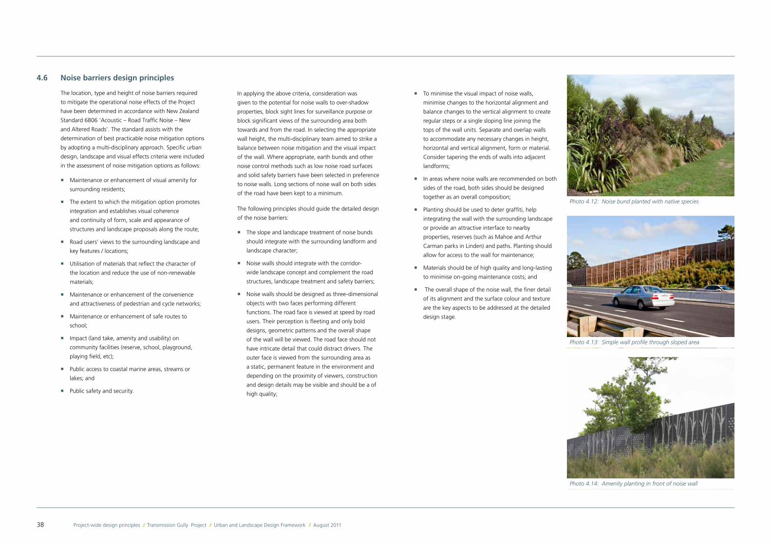
Photo 4.12: Noise bund planted with native species
Photo 4.13: Simple wall profile through sloped area
Photo 4.14: Amenity planting in front of noise wall
4.6 Noise barriers design principles
The location, type and height of noise barriers required
to mitigate the operational noise effects of the Project
have been determined in accordance with New Zealand
Standard 6806 ‘Acoustic – Road Traffic Noise – New
and Altered Roads’. The standard assists with the
determination of best practicable noise mitigation options
by adopting a multi-disciplinary approach. Specific urban
design, landscape and visual effects criteria were included
in the assessment of noise mitigation options as follows:
� Maintenance or enhancement of visual amenity for
surrounding residents;
� The extent to which the mitigation option promotes
integration and establishes visual coherence
and continuity of form, scale and appearance of
structures and landscape proposals along the route;
� Road users’ views to the surrounding landscape and
key features / locations;
� Utilisation of materials that reflect the character of
the location and reduce the use of non-renewable
materials;
� Maintenance or enhancement of the convenience
and attractiveness of pedestrian and cycle networks;
� Maintenance or enhancement of safe routes to
school;
� Impact (land take, amenity and usability) on
community facilities (reserve, school, playground,
playing field, etc);
� Public access to coastal marine areas, streams or
lakes; and
� Public safety and security.
In applying the above criteria, consideration was
given to the potential for noise walls to over-shadow
properties, block sight lines for surveillance purpose or
block significant views of the surrounding area both
towards and from the road. In selecting the appropriate
wall height, the multi-disciplinary team aimed to strike a
balance between noise mitigation and the visual impact
of the wall. Where appropriate, earth bunds and other
noise control methods such as low noise road surfaces
and solid safety barriers have been selected in preference
to noise walls. Long sections of noise wall on both sides
of the road have been kept to a minimum.
The following principles should guide the detailed design
of the noise barriers:
� The slope and landscape treatment of noise bunds
should integrate with the surrounding landform and
landscape character;
� Noise walls should integrate with the corridor-
wide landscape concept and complement the road
structures, landscape treatment and safety barriers;
� Noise walls should be designed as three-dimensional
objects with two faces performing different
functions. The road face is viewed at speed by road
users. Their perception is fleeting and only bold
designs, geometric patterns and the overall shape
of the wall will be viewed. The road face should not
have intricate detail that could distract drivers. The
outer face is viewed from the surrounding area as
a static, permanent feature in the environment and
depending on the proximity of viewers, construction
and design details may be visible and should be a of
high quality;
� To minimise the visual impact of noise walls,
minimise changes to the horizontal alignment and
balance changes to the vertical alignment to create
regular steps or a single sloping line joining the
tops of the wall units. Separate and overlap walls
to accommodate any necessary changes in height,
horizontal and vertical alignment, form or material.
Consider tapering the ends of walls into adjacent
landforms;
� In areas where noise walls are recommended on both
sides of the road, both sides should be designed
together as an overall composition;
� Planting should be used to deter graffiti, help
integrating the wall with the surrounding landscape
or provide an attractive interface to nearby
properties, reserves (such as Mahoe and Arthur
Carman parks in Linden) and paths. Planting should
allow for access to the wall for maintenance;
� Materials should be of high quality and long-lasting
to minimise on-going maintenance costs; and
� The overall shape of the noise wall, the finer detail
of its alignment and the surface colour and texture
are the key aspects to be addressed at the detailed
design stage.
39Transmission Gully Project // Urban and Landscape Design Framework // August 2011 // Project-wide design principles
4.7 Pedestrian and cycle links design principles
The Transmission Gully Project Main Alignment will be a
motorway under section 71 of the Government Roading
Powers Act 1989 (GRPA). Consequently, no pedestrian
or cycle path will be provided alongside the Main
Alignment. Some pedestrian and cycle links will however
be provided in areas where the Project crosses or joins
the local road network, as may be appropriate.
Shared and cycle paths
� Shared paths are for use by pedestrians and low
speed recreational cyclists. Path gradients will be
consistent with NZ accessibility standards where
possible;
� Cycle path gradients should be 10% or less where
possible;
� Shared and cycle paths should be continuous and link
with existing and planned open space and pedestrian
/ cycle networks;
� Shared and cycle paths should be direct and
convenient to use, with vertical and horizontal
alignment variations ‘smoothed out’;
� Shared and cycle paths should provide good amenity
with adequate path width and separation from
carriageways. The berm should be wide enough to
accommodate landscape treatment;
� Locate and design paths and adjacent landscape
treatment to allow informal surveillance between the
path and adjacent road or land use activity;
� Design paths to maximise forward visibility and
minimise the potential for pedestrian-cyclist conflicts;
and
� Any drainage grates should be designed and located
to minimise hazard risk to cyclists and pedestrians.
Cycle lanes
Any cycle lane proposed as part of the Transmission Gully
Project should follow NZTA’s guidelines for cycle lanes. As
a minimum they should comply with the following:
� The width of the cycle lane will vary with the
speed limit of the adjoining road. GTEP Part 14 NZ
Supplement states minimum widths of 1.5m, 1.9m
and 2.5m for speed limits of 50kph, 70kph and
100kph respectively;
� Cycle lanes should have an even and continuous
sealed surface;
� Cycle lanes should be identified by cycle pavement
marking symbols. Other distinguishing features such
as coloured surface may also be used; and
� Audio-tactile pavement marking should be used
to make the edge of the carriageway unless this is
precluded because of proximity to adjacent residential
properties.
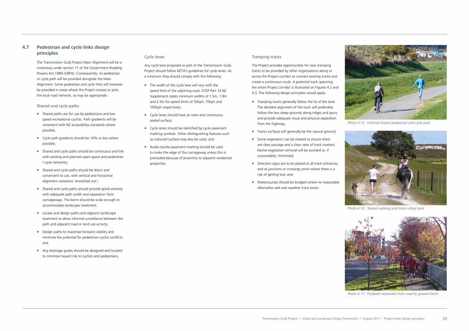
Photo 4.15: Informal shared pedestrian and cycle path
Photo 4.16: Shared walking and horse riding track
Photo 4.17: Footpath separated from road by grassed berm
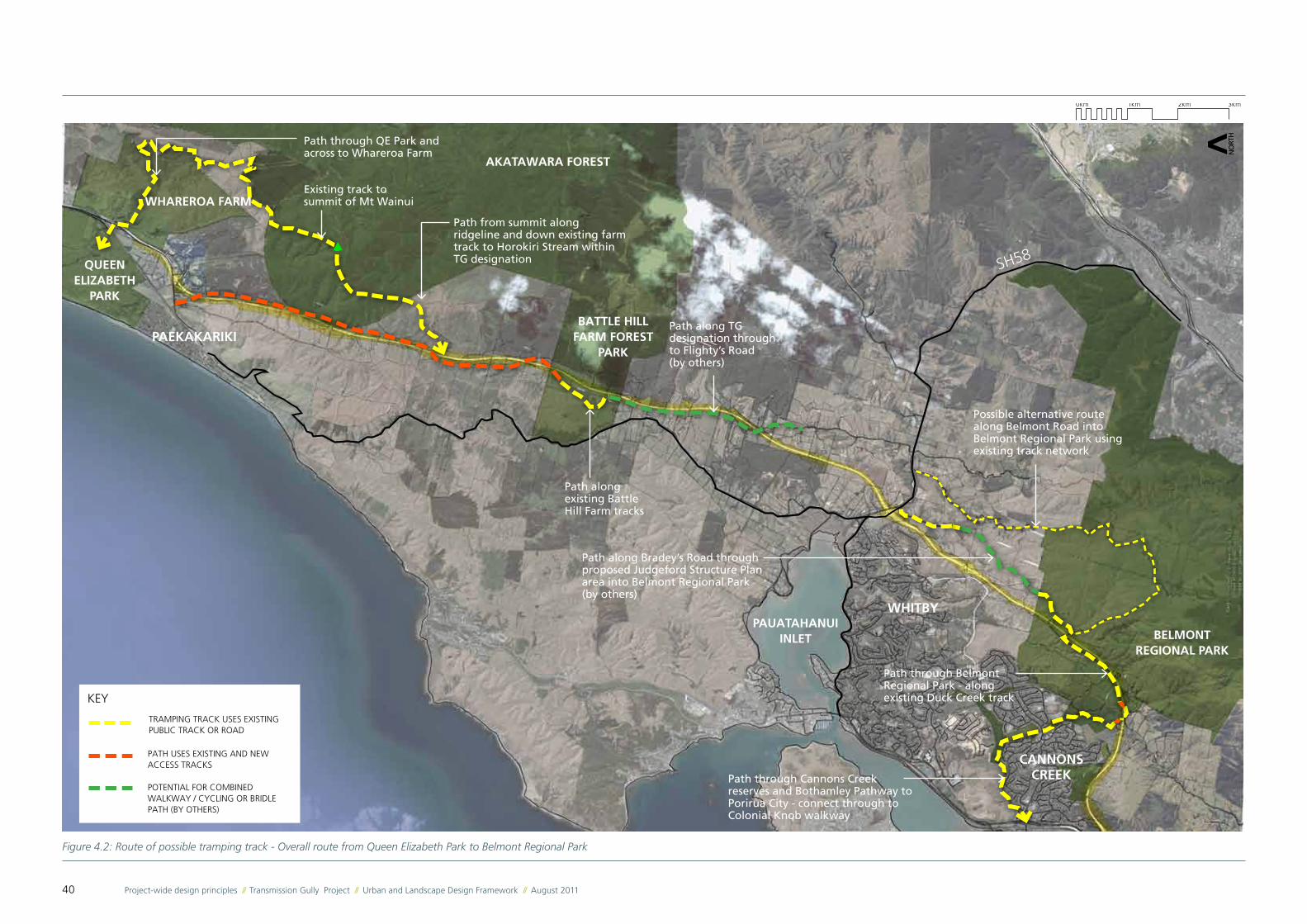
Tramping tracks
The Project provides opportunities for new tramping
tracks to be provided by other organisations along or
across the Project corridor to connect existing tracks and
create a continuous route. A potential track spanning
the entire Project corridor is illustrated on Figures 4.2 and
4.3. The following design principles would apply:
� Tramping tracks generally follow the lie of the land.
The detailed alignment of the track will preferably
follow the less steep grounds along ridges and spurs
and provide adequate visual and physical separation
from the highway;
� Tracks surfaces will generally be the natural ground;
� Some vegetation can be cleared to ensure there
are clear passage and a clear view of track markers.
Native vegetation removal will be avoided or, if
unavoidable, minimised;
� Direction signs are to be placed at all track entrances,
and at junctions or crossings point where there is a
risk of getting lost; and
� Watercourses should be bridged where no reasonable
alternative safe wet weather track exists.
40 Project-wide design principles // Transmission Gully Project // Urban and Landscape Design Framework // August 2011
Figure 4.2: Route of possible tramping track - Overall route from Queen Elizabeth Park to Belmont Regional Park
AKATAWARA FOREST
BATTLE HILL FARM FOREST
PARK
WHAREROA FARM
QUEEN ELIZABETH
PARK
BELMONT REGIONAL PARK
Path along Bradey’s Road through proposed Judgeford Structure Plan area into Belmont Regional Park (by others)
Path through Belmont Regional Park - along existing Duck Creek track
Path through Cannons Creek reserves and Bothamley Pathway to Porirua City - connect through to Colonial Knob walkway
Path through QE Park and across to Whareroa Farm
Existing track to summit of Mt Wainui
Path from summit along ridgeline and down existing farm track to Horokiri Stream within TG designation
Path along existing Battle Hill Farm tracks
Path along TG designation through to Flighty’s Road (by others)
SH58
WHITBY
CANNONS CREEK
PAEKAKARIKI
KEY
TRAMPING TRACK USES EXISTING PUBLIC TRACK OR ROAD
PATH USES EXISTING AND NEW ACCESS TRACKS
POTENTIAL FOR COMBINED WALKWAY / CYCLING OR BRIDLE PATH (BY OTHERS)
Possible alternative route along Belmont Road into Belmont Regional Park using existing track network
PAUATAHANUIINLET
41Transmission Gully Project // Urban and Landscape Design Framework // August 2011 // Project-wide design principles
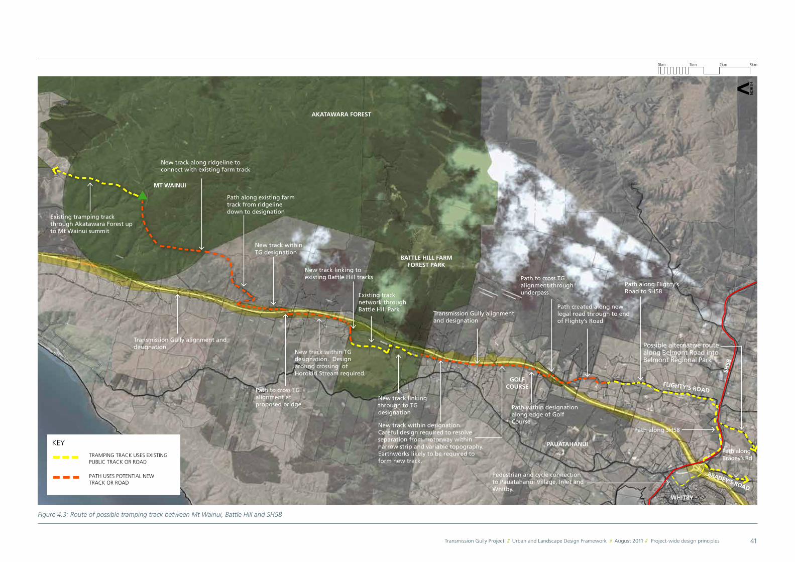
Figure 4.3: Route of possible tramping track between Mt Wainui, Battle Hill and SH58
BATTLE HILL FARM FOREST PARK
Path along Flighty’s Road to SH58
Path along SH58
Path along Bradey’s Rd
Pedestrian and cycle connection to Pauatahanui Village, Inlet and Whitby.
WHITBY
PAUATAHANUI
GOLF COURSE
Path created along new legal road through to end of Flighty’s Road
Path to cross TG alignment through underpass
Path within designation along edge of Golf Course
New track linking through to TG designation
Existing track network through Battle Hill Park
New track within designation. Careful design required to resolve separation from motorway within narrow strip and variable topography. Earthworks likely to be required to form new track.
SH58
Transmission Gully alignment and designation
FLIGHTY’S ROAD
BRADEY’S ROAD
AKATAWARA FOREST
Existing tramping track through Akatawara Forest up to Mt Wainui summit
New track along ridgeline to connect with existing farm track
Path along existing farm track from ridgeline down to designation
New track within TG designation
Path to cross TG alignment at proposed bridge
New track within TG designation. Design around crossing of Horokiri Stream required.
New track linking to existing Battle Hill tracks
MT WAINUI
Transmission Gully alignment and designation Possible alternative route
along Belmont Road into Belmont Regional Park
KEY
TRAMPING TRACK USES EXISTING PUBLIC TRACK OR ROAD
PATH USES POTENTIAL NEW TRACK OR ROAD
42 Project-wide design principles // Transmission Gully Project // Urban and Landscape Design Framework // August 2011
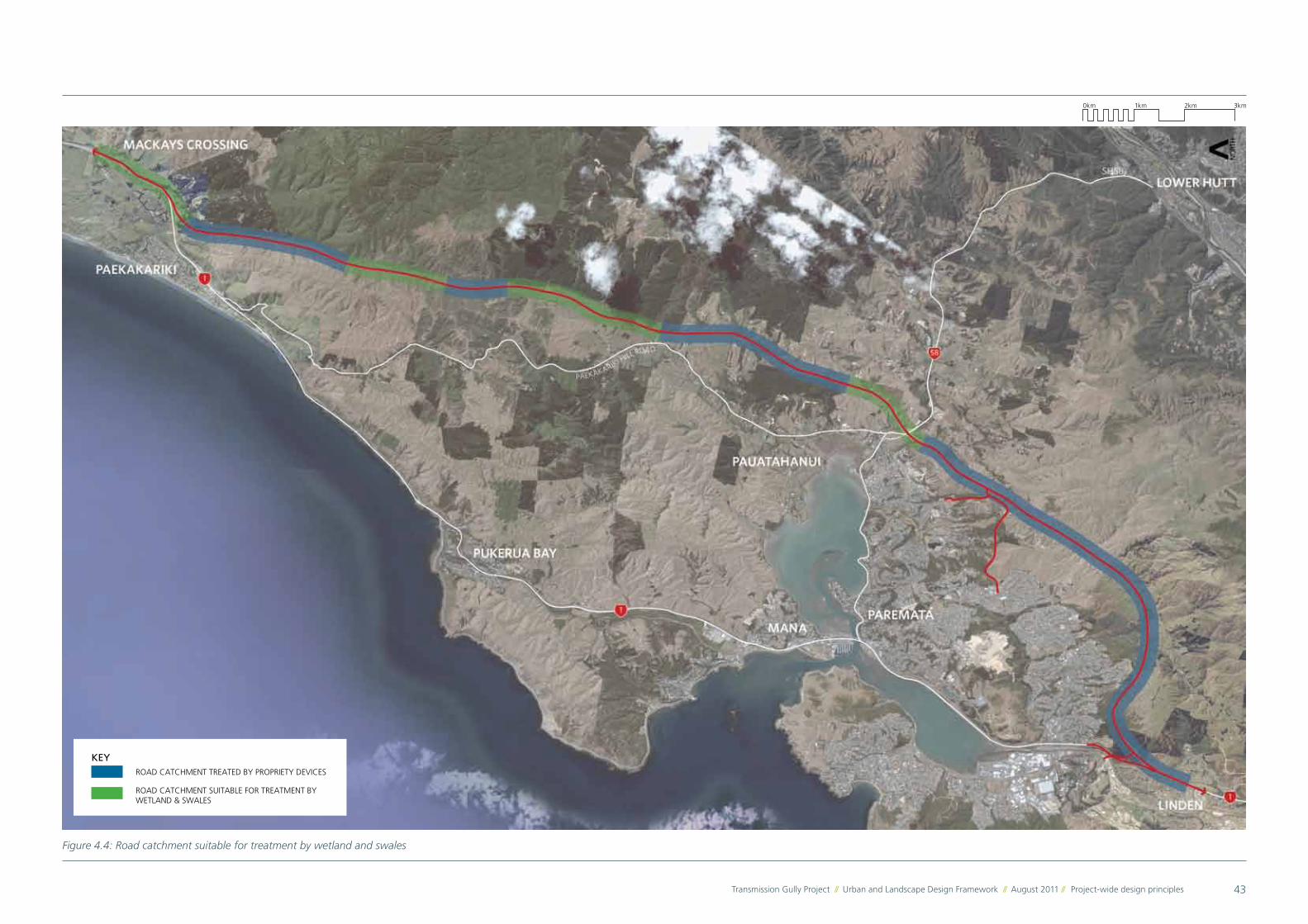
4.8 Stormwater devices design principles
Stormwater ‘treatment trains’ combine the functions of
two or more different stormwater treatment methods
to provide improved treatment capabilities, to reduce
the risk of environmental impacts if one part of the
system fails or is being maintained and to achieve other
objectives such as flood mitigation and aquatic ecosystem
protection. A common treatment train combines
sumps (to trap gross pollutants) swales and wetlands.
Treatment trains including swales and wetlands have
been recommended along this alignment wherever the
site conditions (primarily topography and soil type) are
suitable. The location of wetlands and swales is shown
on Figure 4.4.
Wetlands
� Wetlands are preferred over deeper ponds as they
minimise drowning hazards and have better overall
water quality treatment;
� Wetlands should be designed with the multiple roles
of stormwater treatment, landscape amenity feature
and ecological habitat;
� Optimise the natural character of wetlands through
their shape, edge profile and landscape treatment;
� Integrate recommended wetlands with the
surrounding pedestrian and cycle networks;
� Design the edge of wetlands to be shallow and
vegetated so as to prevent accidental access whilst
reducing the need for fencing; and
� Integrate recommended wetlands with natural
stream environments to connect them visually and
ecologically, if not hydrologically.
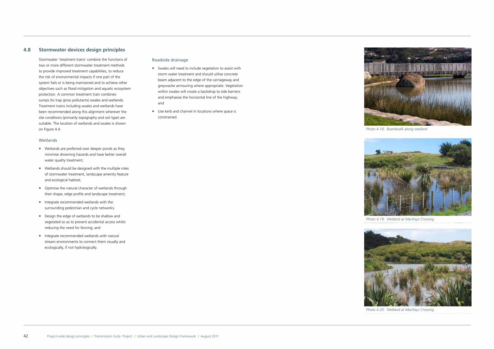
Photo 4.18: Boardwalk along wetland
Photo 4.19: Wetland at MacKays Crossing
Photo 4.20: Wetland at MacKays Crossing
Roadside drainage
� Swales will need to include vegetation to assist with
storm water treatment and should utilise concrete
beam adjacent to the edge of the carriageway and
greywacke armouring where appropriate. Vegetation
within swales will create a backdrop to side barriers
and emphasise the horizontal line of the highway;
and
� Use kerb and channel in locations where space is
constrained.
43Transmission Gully Project // Urban and Landscape Design Framework // August 2011 // Project-wide design principles
KEYROAD CATCHMENT TREATED BY PROPRIETY DEVICES
ROAD CATCHMENT SUITABLE FOR TREATMENT BY WETLAND & SWALES
Figure 4.4: Road catchment suitable for treatment by wetland and swales
44 Project-wide design principles // Transmission Gully Project // Urban and Landscape Design Framework // August 2011
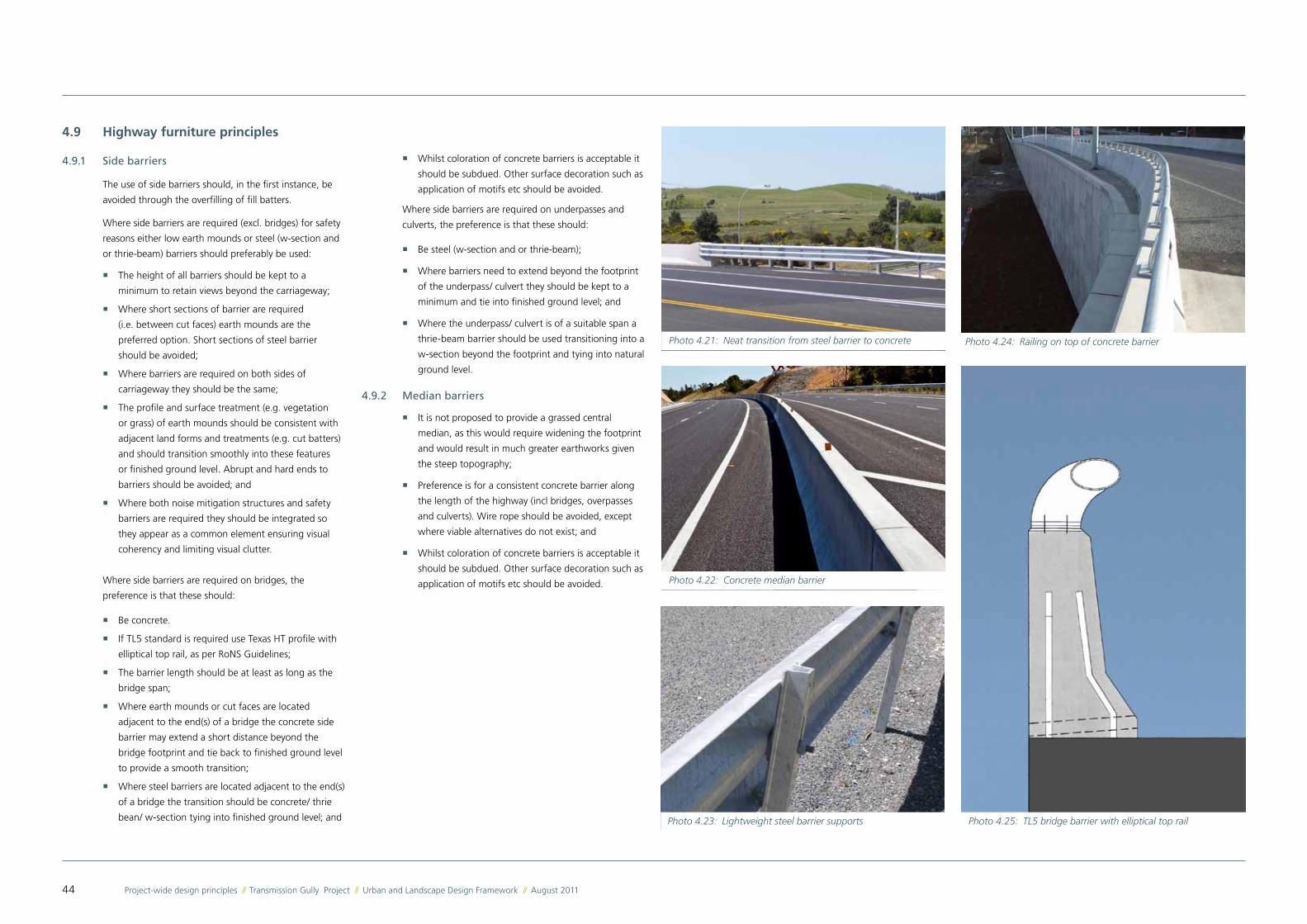
Photo 4.21: Neat transition from steel barrier to concrete
Photo 4.22: Concrete median barrier
4.9 Highway furniture principles
4.9.1 Side barriers
The use of side barriers should, in the first instance, be
avoided through the overfilling of fill batters.
Where side barriers are required (excl. bridges) for safety
reasons either low earth mounds or steel (w-section and
or thrie-beam) barriers should preferably be used:
� The height of all barriers should be kept to a
minimum to retain views beyond the carriageway;
� Where short sections of barrier are required
(i.e. between cut faces) earth mounds are the
preferred option. Short sections of steel barrier
should be avoided;
� Where barriers are required on both sides of
carriageway they should be the same;
� The profile and surface treatment (e.g. vegetation
or grass) of earth mounds should be consistent with
adjacent land forms and treatments (e.g. cut batters)
and should transition smoothly into these features
or finished ground level. Abrupt and hard ends to
barriers should be avoided; and
� Where both noise mitigation structures and safety
barriers are required they should be integrated so
they appear as a common element ensuring visual
coherency and limiting visual clutter.
Where side barriers are required on bridges, the
preference is that these should:
� Be concrete.
� If TL5 standard is required use Texas HT profile with
elliptical top rail, as per RoNS Guidelines;
� The barrier length should be at least as long as the
bridge span;
� Where earth mounds or cut faces are located
adjacent to the end(s) of a bridge the concrete side
barrier may extend a short distance beyond the
bridge footprint and tie back to finished ground level
to provide a smooth transition;
� Where steel barriers are located adjacent to the end(s)
of a bridge the transition should be concrete/ thrie
bean/ w-section tying into finished ground level; and
� Whilst coloration of concrete barriers is acceptable it
should be subdued. Other surface decoration such as
application of motifs etc should be avoided.
Where side barriers are required on underpasses and
culverts, the preference is that these should:
� Be steel (w-section and or thrie-beam);
� Where barriers need to extend beyond the footprint
of the underpass/ culvert they should be kept to a
minimum and tie into finished ground level; and
� Where the underpass/ culvert is of a suitable span a
thrie-beam barrier should be used transitioning into a
w-section beyond the footprint and tying into natural
ground level.
4.9.2 Median barriers
� It is not proposed to provide a grassed central
median, as this would require widening the footprint
and would result in much greater earthworks given
the steep topography;
� Preference is for a consistent concrete barrier along
the length of the highway (incl bridges, overpasses
and culverts). Wire rope should be avoided, except
where viable alternatives do not exist; and
� Whilst coloration of concrete barriers is acceptable it
should be subdued. Other surface decoration such as
application of motifs etc should be avoided.
Photo 4.24: Railing on top of concrete barrier
Photo 4.23: Lightweight steel barrier supports Photo 4.25: TL5 bridge barrier with elliptical top rail
45Transmission Gully Project // Urban and Landscape Design Framework // August 2011 // Project-wide design principles
4.9.3 Lighting Columns
Lights are not required for the majority of the Main
Alignment, which will reduce the potential visual clutter
and night-time light effects. Lights are only recommended
in the vicinity of the interchanges and the short section of
the Main Alignment between the SH58 and James Cook
Interchanges. In these areas:
� Design light standards as part of a coherent suite of
highway furniture, and to be visually recessive;
� Adopt steel light standards with a plain galvanised
finish;
� Preference is for light standards with either a sharp
angle between pole and arm, or fix fittings directly to
the pole;
� Use consistent heights within each group of light
standards (for instance within each interchange) in
order to reduce visual clutter; and
� Adopt consistent column design for CCTV cameras.
4.9.4 Protection of Roadside Furniture
� Configure edge barriers in such a way to avoid the
need for additional protection of structures or utilities
adjacent to the highway; and
� Use frangible elements in any locations where there
are no edge barriers to provide protection.
4.9.5 CCTV
� Adopt design for CCTV camera standards that is
either combined or consistent with light standards.
4.9.6 Sign Gantries and Signage Posts
� Construct gantries so that beams and pillars join at
right angles. Preference is for square box section, I
beams and flat steel components.
� Construct pillars to prevent unauthorised access
without the need for such secondary fittings as
barbed wire;
� Use simple steel posts for smaller signs installed
adjacent to highway;
� Paint gantries a metallic colour that complements
weathered galvanised steel;
� Where possible, signage should be visually contained
within the depth of the spanning girder, through
integrated design of girders and signage panels.
� Signage for road users is not permitted to be
mounted on pedestrian overbridges (if present).
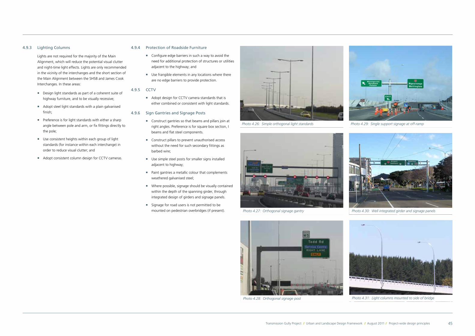
Photo 4.26: Simple orthogonal light standards
Photo 4.27: Orthogonal signage gantry
Photo 4.28: Orthogonal signage post
Photo 4.29: Single support signage at off-ramp
Photo 4.30: Well integrated girder and signage panels
Photo 4.31: Light columns mounted to side of bridge