4. EMU17 & MEU17 Programming Instructions 3. To … · Programming sequence Note: Button pauses...
7
Timer Modules Without Housing MEU11 (24 Hour) MEU17 (7 Day) With Housing (Giving Panel Mount Capability) EMU11 (24 Hour) EMU17 (7 Day) INSTALLATION & OPERATING INSTRUCTIONS Panel MASTER ON
Transcript of 4. EMU17 & MEU17 Programming Instructions 3. To … · Programming sequence Note: Button pauses...

Timer ModulesWithout Housing
MEU11 (24 Hour) MEU17 (7 Day)With Housing
(Giving Panel Mount Capability)EMU11 (24 Hour) EMU17 (7 Day)
INS
TA
LL
AT
ION
& O
PE
RA
TIN
GIN
ST
RU
CT
ION
S
PanelMASTER
ON
7
Programming sequence
Note: Button pauses greater than 1 minute during programming will result inautomatic return to the operating mode.
2 Setting Clock (after reset)i Hour Setting - Press the <Change> button to advance
the hour setting.Note: For rapid hour selections press and hold down <Change> button.
ii Minute Setting - Press the <Program> button once to select the minutes - display shows clock symbol and minute digits flashing. Press the <Change> button to advance the minutes setting. Note: For rapid minute selection press and hold down <Change> button. (Note: 16 hrs shown as example of hrs set)
iii Press <Program> button once - clock is now set and display shows ready for the first ON programme timewith ON and hours digits flashing.
3. To Set Programme ON/OFF Times (after clock setting)Programme 1 ON time
i Press <Change> button to advance the hour setting.
ii Press <Program> button once to select minute time - display shows minute digits and ON flashing. Press <Change> button to advance minute setting. (Note: 16 hrs shown as example of hours set).
Setting clockProgramme 1 ONProgramme 1 OFFProgramme 2 ONProgramme 2 OFF
Programme 3 ONProgramme 3 OFFProgramme 4 ONProgramme 4 OFFOperating Mode
::::::. . . . . .
. . . . ➔
1 2 3 4
1 2 3 4
1 2 3 4
1 2 3 4
8
iii Press <Program> button once - the first ON time is now set and display shows ready for the first OFF programme time.
iv Now set the hrs and minutes as before.
v Repeat steps i to iv to set the remainder of the 3 ON/OFF times as required.Note: Any unused ON/OFF programme should be skipped until the displayshows normal operating mode. Do not programme ‘0’s into unusedprogrammes.
IMPORTANT After setting a clock time which falls within a programmed ONperiod, the unit will not switch ON. Use the Change button to switch unit ON.After this the unit will operate normally to the programmes set.
4. Programme ReviewTo fast review the set programmes or for quick exit to normal operating mode -press and hold the <Program> button.
5. Initiating Programme ModeThis can be initiated any time during the normal operating mode. Press<Program> button and the Clock symbol, hrs and minutes symbols on thedisplay will flash - this is review mode. If any change to programmes isrequired press <Change> button to initiate programme mode and then followsteps 2 and 3.
6. Cancelling ProgrammesAny ON/OFF programme can be cancelled by clearing its ON and OFF time.Follow step 5 and when into the ON or OFF programme to be cancelled pressthe <Change> button until the hour digits show -- :then press the <Program> button to clear the programme. The display will show the hour and minute digits and ON or OFF flashing.
Self Cancelling OverrideTo change the output status from ON to OFF or vice versa during normal operationpress the <Change> button. The output status will change and indicate override is inoperation by flashing.
1 2 3 4
ON
1 2 3 4
1 To Reset DisplayTo clear programmes from memory and reset the time controller press and holddown both buttons until the display goes blank. Release buttons and display willfill with its complete range of characters and then clear to show clock and day 1 symbol flashing.You are now in the clock setting mode at the beginning of the programme sequence
1211109
Easy view 24hour digitalclock/timerdisplay
Change Buttonsets Day(s), Hoursand Minute timesand self cancellingoverride
Programme Buttonused to select the
clock time and the 6ON/OFF programme
times and to reviewthem once set
Output Statusshowing unit
either ON or OFF
BatteryThis product has a factory fitted rechargeable battery. If the time controller is left withits mains power switched off for more than 1 month the display may go blank. Inthis case switch mains on, wait 30 mins, and apply reset - see 1 before programming.
ProgrammingThis is a seven day (weekly) timeswitch which has six programmes, each of whichcan be block programmed to work on all of the five weekdays, both weekend days,or all 7seven days (24 hour operation). Programmes can also be designated tooperate on individual days.Only two setting buttons are required, Change and Program. In normal use theChange button is used to switch ON or OFF, overriding the timeswitch until thenext programmed OFF or ON time. During programming the Change button isused to set the hours, minutes and days. The Program button is only used whensetting or adjusting the clock time and day or the 6 programmed ON/OFF timesand days, although it can also be used to review the ON/OFF times and days oncethey have been set. Each time the Program button is pressed the display will flasheither the days, hours or minutes in turn, starting with the clock then the first ONtime and day(s), first OFF time, second ON time and day(s) etc. Wherever thedays, hours or minutes are flashing they may be set using the Change button. Onceset the Program button is pressed again to proceed to the next stage.
Normal Operating ModeIn normal operation the PanelMaster will display the correct day and its time with the colon flashing. The output status will be shown by either ON or OFF on the display.
2 Setting Clock (after reset)i Day Setting - Press <Change> button to advance to the day required.
Day 1 = Monday and Day 7 = Sunday.ii Hour Setting - Press the <Program> button once to
select the hour - display shows clock symbol and the hrsdigit flashing. Press the <Change> button to advance the hour setting.Note: For rapid hour selections press and hold down <Change> button.
iii Minute Setting - Press the <Program> button once to select the minutes - display shows with clock symbol and minute digits flashing. Press the <Change> button to advance the minutes setting. Note: For rapid minute selection press and hold down <Change> button. (Note: 16 hrs shown as example of hrs set)
iv Press <Program> button once - clock is now set and display shows ready for the first ON programme time.
ii Once day option selected press <Program> button once to select hour time - display shows hour digits and ON flashing. Press <Change> button to advance hour setting.(Note: Monday shown as an example of days set).
iii Press <Program> button once to select minute time - display shows minute digits and ON flashing. Press <Change> button to advance minute setting. (Note: 16 hrs shown as example of hours set).
iv Press <Program> button once - the first ON time is now set and display shows ready for the first OFF programme time.
v Now set the hrs and minutes as before. The day(s) selected remains the same.
vi Repeat steps i to v to set the remainder of the 5 ON/OFF times as required. Note:Any unused ON/OFF programme should be skipped until the display showsnormal operating mode. Do not programme ‘0’s into unused programmes.
IMPORTANT After setting a clock time which falls within a programmed ONperiod, the unit will not switch ON. Use the Change button to switch unit ON.After this the unit will operate normally to the programmes set.
4. EMU17 & MEU17 Programming Instructions
Day indicator 1 = Monday 7 = Sunday
Setting clockProgramme 1 ONProgramme 1 OFFProgramme 2 ONProgramme 2 OFFProgramme 3 ONProgramme 3 OFF
Programme 4 ONProgramme 4 OFFProgramme 5 ONProgramme 5 OFFProgramme 6 ONProgramme 6 OFFOperating Mode
::::::::. . . . . .
. . . . ➔
4. Programme ReviewTo fast review the set programmes or for quick exit to normal operating mode -press and hold the <Program> button.
5. Initiating Programme ModeThis can be initiated any time during the normal operating mode. Press<Program> button and the Clock symbol, day flag, hrs and minutes symbolson the display will flash - this is review mode. If any change to programmes isrequired press <Change> button to initiate programme mode and then followsteps 2 and 3.
6. Cancelling ProgrammesAny ON/OFF programme can be cancelled by clearing its ON and OFF time.Follow step 5 and when into the ON or OFF programme to be cancelled pressthe <Change> button until the hour digits show -- :then press the <Program> button to clear the programme. The display will show the hour andminute digits and ON or OFF flashing.(Note: Monday shown as an example of days set).
Self Cancelling OverrideTo change the output status from ON to OFF or vice versa during normal operationpress the <Change> button. The output status will change and indicate override is inoperation by flashing.
OFF
1 2 3 4 5 6 7
1 2 3 4 5 6 7
1 2 3 4 5 6 7
1 2 3 4 5 6 7
ON
1 2 3 4 5 6 7
ON
1 2 3 4 5 6 7
ON
1 2 3 4 5 6 7
OFF
1 2 3 4 5 6 7
ON
1 2 3 4 5 6 7
●
Programming sequence
Note: Button pauses greater than 1 minute during programming will result inautomatic return to the operating mode.
1 2 3 4 5 6 7● ● ● ● ● = 5 days (Weekdays) Mo Tu We Th Fr
● ● = 2 days (Weekend) Sa Su● ● ● ● ● ● ● = 7 days (Everyday) Mo Tu We Th Fr Sa Su● = Individual days Starting with Monday through to Sunday
3. To Set Programme ON/OFF Times (after clock setting)Programme 1 ON time
i Press <Change> button to advance the day flag to the required day(s) settingswhich are:

HELPLINE020-8450-8944
Designed and manufactured in the U.K. 67-057-97 (2)
For a product brochure please contact:Timeguard Ltd.
Victory Park, 400 Edgware Road,London NW2 6NDTel: 020 8452 1112
or email [email protected]
4 5 6321
Tamper proofcover
Single Resistor PSU (MEU11 & MEU17 only) Two Resistor PSU - gives Optimum EMC Performance(MEU11 & MEU17 only)
Bezel for panelmounting
MetalHydrideBattery
Pin HeaderChangebutton
Programmebutton
Panel mountbolts
Slide switch allowingcontinuous ON or
OFF or programmedoperation
Surfacemount fixing
Figure 1
Fig 2
Fig 3
Fig 4
Fig 5
Contents1 EMU11 (24 hour) or EMU17 (7 day)1 Panel mount bezel1 Tamper proof cover4 Surface mount stand offs (length 10mm)2 Panel mount bolts2 Self-tapping screws (No. 4 x 5/8 in) for panel mount bolts2 Self-tapping screws (No.6 x 3/8 in) for attaching bezel to EMU11/17
Installation - Panel MountingFor panel mounting (in panels up to 7.0mm thickwith the cut-out as shown in figure 2) theEMU11/17 should be snapped into the bezelsupplied and secured in place by the use of the 2No. 6 x 3/8in self-tapping screws provided asshown in figure 3.When selecting a position for the unit it should beborn in mind that a clearance behind the frontpanel surface of 26.0mm is required over the fullarea of the panel cut-out.The unit is designed to be mounted from the frontof the panel by the following procedure:a. Insert the 2 bolts provided in the locations
shown in figure 4.b. Then insert the 2 No. 4 x 5/8 in self-tapping
screws into the bolts and engage thread.c. Make connections to the unit by wires
terminated in a Molex 4 way 7720 or similarconnector from behind the panel.
d. Insert the EMU11/17 complete with bezel intothe panel and tighten up the 2 No. 4 self-tapping screws. The ears on the bolts willrotate under the tightening action to clamp theunit to the panel.
Surface MountingThe EMU11/17 without bezel can be surfacemounted using the 4 securing holes as shownin figure 5. The unit can be stood off from themounting surface by 10mm using the 4 spacersif required. Screws are not provided and itmust be remembered that if used in this waythe EMU11/17 must be installed within ahousing or cubicle to prevent access to themains terminations.
Easy view 24hour digitalclock/timerdisplay
Change Buttonsets Hours andMinute times andself cancellingoverride
Programme Buttonused to select the
clock time and the 4ON/OFF
programme timesand to review them
once set
Output Statusshowing unit
either ON or OFFBatteryThis product has a factory fitted rechargeable battery. If the time controller is left withits mains power switched off for more than 1 month the display may go blank. In thiscase switch mains on, wait 30 minutes, and apply reset - see 1 before programming.ProgrammingOnly two setting buttons are required, Change and Program. In normal use the Changebutton is used to switch ON or OFF, overriding the timeswitch until the nextprogrammed OFF or ON time. During programming the Change button is used to setthe hours and minutes. The Program button is only used when setting or adjusting theclock time or the 4 programmed ON/OFF times, although it can also be used to reviewthe ON/OFF times once they have been set. Each time the Program button is pressed thedisplay will flash either the hours or minutes in turn, starting with the clock then the firstON time, first OFF time, second ON time etc. Wherever the hours or minutes areflashing they may be set using the Change button. Once set the Program button ispressed again to proceed to the next stage.Normal Operating ModeIn normal operation the PanelMaster will display the correct time with the colon flashing. The output status will be shown by either ON or OFF on the display. 1 To Reset DisplayTo clear programmes from memory and reset the time controller press and holddown both buttons until the display goes blank. Release buttons and display will fill with its completerange of characters and then clear to show clock and hour digit flashing.You are now in the clock setting mode at the beginning of the programme sequence
3. EMU11 & MEU11 Programming Instructions1. Physical Arrangements & Installation Instructions
1 2 3 4
1 2 3 4
67mm
R 3.5mm67m
m
Use No. 6 x 3/8in self-tapping screws to fullysecure bezel to EMU11/17(fixed from rear)
Bezel
No. 4 x 5/8in self-tapping screw
4 fixingholes forsurfacemounting
Bolt
EMU 11 & EMU 17
MEU 11 & MEU 17
Engineering drawing can be supplied on request
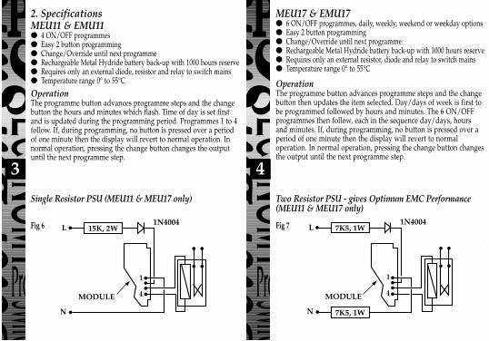
All TypesConnectionsPin 1: Common.Pin 2: Positive battery charge plus relay current. Min 0.50 mA (No relay).Pin 3: Relay connection.Pin 4: Output & relay connection. NPN open connector. Max 10 mA, 47 VA Molex 7720 4 way connector or similar is recommended.MEU11 and MEU17 - Typical UsageThe examples in figs 6, 7 and 8 show the module driving a Shrack 48Vrelay with power derived from the mains. Type RP330048 or RP331048(Changeover contracts). In these configurations the relay pulls in at 47Vand is held at above 24V with mains voltages down to 200V.EMU11 and EMU17 - Typical UsageIn this case the circuit in fig 6 can be used with a 10K, 3W resistor in place of the15K, 2W resistor shown and a 1.3W zener must be connected between pins 1and 2 of the module. The circuit in fig 7 can be used with two 5K1, 1.5Wresistors in place of the 7K5, 1W resistors shown and a 1.3W zener must beconnected between pins 1 and 2 of the module. The circuit in fig 8 can be usedwith a 330nF, X 250V ac capacitor instead of the 220nf capacitor shown and a1.3W zener must be connected between pins 1 and 2 of the module.In all cases the zener is 47V and its cathode is connected to module pin 2.
Fig 7Fig 6
Fig 8
2. SpecificationsMEU11 & EMU11● 4 ON/OFF programmes● Easy 2 button programming● Change/Override until next programme● Rechargeable Metal Hydride battery back-up with 1000 hours reserve● Requires only an external diode, resistor and relay to switch mains● Temperature range 0° to 55°C
OperationThe programme button advances programme steps and the changebutton the hours and minutes which flash. Time of day is set firstand is updated during the programming period. Programmes 1 to 4follow. If, during programming, no button is pressed over a periodof one minute then the display will revert to normal operation. Innormal operation, pressing the change button changes the outputuntil the next programme step.
MEU17 & EMU17● 6 ON/OFF programmes, daily, weekly, weekend or weekday options● Easy 2 button programming● Change/Override until next programme● Rechargeable Metal Hydride battery back-up with 1000 hours reserve● Requires only an external resistor, diode and relay to switch mains● Temperature range 0° to 55°C
OperationThe programme button advances programme steps and the changebutton then updates the item selected. Day/days of week is first tobe programmed followed by hours and minutes. The 6 ON/OFFprogrammes then follow, each in the sequence day/days, hoursand minutes. If, during programming, no button is pressed over aperiod of one minute then the display will revert to normaloperation. In normal operation, pressing the change button changesthe output until the next programme step.
It is possible to operate these modules from other voltages.Please contact Technical Service on 020 8450 0515 for advice.
Capacitor PSU (MEU11 & MEU17 only)
HELPLINE020-8450-8944
Designed and manufactured in the U.K. 67-057-97 (2)
For a product brochure please contact:Timeguard Ltd.
Victory Park, 400 Edgware Road,London NW2 6NDTel: 020 8452 1112
or email [email protected]
4 5 6321
Tamper proofcover
Single Resistor PSU (MEU11 & MEU17 only) Two Resistor PSU - gives Optimum EMC Performance(MEU11 & MEU17 only)
Bezel for panelmounting
MetalHydrideBattery
Pin HeaderChangebutton
Programmebutton
Panel mountbolts
Slide switch allowingcontinuous ON or
OFF or programmedoperation
Surfacemount fixing
Figure 1
Fig 2
Fig 3
Fig 4
Fig 5
Contents1 EMU11 (24 hour) or EMU17 (7 day)1 Panel mount bezel1 Tamper proof cover4 Surface mount stand offs (length 10mm)2 Panel mount bolts2 Self-tapping screws (No. 4 x 5/8 in) for panel mount bolts2 Self-tapping screws (No.6 x 3/8 in) for attaching bezel to EMU11/17
Installation - Panel MountingFor panel mounting (in panels up to 7.0mm thickwith the cut-out as shown in figure 2) theEMU11/17 should be snapped into the bezelsupplied and secured in place by the use of the 2No. 6 x 3/8in self-tapping screws provided asshown in figure 3.When selecting a position for the unit it should beborn in mind that a clearance behind the frontpanel surface of 26.0mm is required over the fullarea of the panel cut-out.The unit is designed to be mounted from the frontof the panel by the following procedure:a. Insert the 2 bolts provided in the locations
shown in figure 4.b. Then insert the 2 No. 4 x 5/8 in self-tapping
screws into the bolts and engage thread.c. Make connections to the unit by wires
terminated in a Molex 4 way 7720 or similarconnector from behind the panel.
d. Insert the EMU11/17 complete with bezel intothe panel and tighten up the 2 No. 4 self-tapping screws. The ears on the bolts willrotate under the tightening action to clamp theunit to the panel.
Surface MountingThe EMU11/17 without bezel can be surfacemounted using the 4 securing holes as shownin figure 5. The unit can be stood off from themounting surface by 10mm using the 4 spacersif required. Screws are not provided and itmust be remembered that if used in this waythe EMU11/17 must be installed within ahousing or cubicle to prevent access to themains terminations.
Easy view 24hour digitalclock/timerdisplay
Change Buttonsets Hours andMinute times andself cancellingoverride
Programme Buttonused to select the
clock time and the 4ON/OFF
programme timesand to review them
once set
Output Statusshowing unit
either ON or OFFBatteryThis product has a factory fitted rechargeable battery. If the time controller is left withits mains power switched off for more than 1 month the display may go blank. In thiscase switch mains on, wait 30 minutes, and apply reset - see 1 before programming.ProgrammingOnly two setting buttons are required, Change and Program. In normal use the Changebutton is used to switch ON or OFF, overriding the timeswitch until the nextprogrammed OFF or ON time. During programming the Change button is used to setthe hours and minutes. The Program button is only used when setting or adjusting theclock time or the 4 programmed ON/OFF times, although it can also be used to reviewthe ON/OFF times once they have been set. Each time the Program button is pressed thedisplay will flash either the hours or minutes in turn, starting with the clock then the firstON time, first OFF time, second ON time etc. Wherever the hours or minutes areflashing they may be set using the Change button. Once set the Program button ispressed again to proceed to the next stage.Normal Operating ModeIn normal operation the PanelMaster will display the correct time with the colon flashing. The output status will be shown by either ON or OFF on the display. 1 To Reset DisplayTo clear programmes from memory and reset the time controller press and holddown both buttons until the display goes blank. Release buttons and display will fill with its completerange of characters and then clear to show clock and hour digit flashing.You are now in the clock setting mode at the beginning of the programme sequence
3. EMU11 & MEU11 Programming Instructions1. Physical Arrangements & Installation Instructions
1 2 3 4
1 2 3 4
67mm
R 3.5mm67m
m
Use No. 6 x 3/8in self-tapping screws to fullysecure bezel to EMU11/17(fixed from rear)
Bezel
No. 4 x 5/8in self-tapping screw
4 fixingholes forsurfacemounting
Bolt
EMU 11 & EMU 17
MEU 11 & MEU 17
Engineering drawing can be supplied on request
All TypesConnectionsPin 1: Common.Pin 2: Positive battery charge plus relay current. Min 0.50 mA (No relay).Pin 3: Relay connection.Pin 4: Output & relay connection. NPN open connector. Max 10 mA, 47 VA Molex 7720 4 way connector or similar is recommended.MEU11 and MEU17 - Typical UsageThe examples in figs 6, 7 and 8 show the module driving a Shrack 48Vrelay with power derived from the mains. Type RP330048 or RP331048(Changeover contracts). In these configurations the relay pulls in at 47Vand is held at above 24V with mains voltages down to 200V.EMU11 and EMU17 - Typical UsageIn this case the circuit in fig 6 can be used with a 10K, 3W resistor in place of the15K, 2W resistor shown and a 1.3W zener must be connected between pins 1and 2 of the module. The circuit in fig 7 can be used with two 5K1, 1.5Wresistors in place of the 7K5, 1W resistors shown and a 1.3W zener must beconnected between pins 1 and 2 of the module. The circuit in fig 8 can be usedwith a 330nF, X 250V ac capacitor instead of the 220nf capacitor shown and a1.3W zener must be connected between pins 1 and 2 of the module.In all cases the zener is 47V and its cathode is connected to module pin 2.
Fig 7Fig 6
Fig 8
2. SpecificationsMEU11 & EMU11● 4 ON/OFF programmes● Easy 2 button programming● Change/Override until next programme● Rechargeable Metal Hydride battery back-up with 1000 hours reserve● Requires only an external diode, resistor and relay to switch mains● Temperature range 0° to 55°C
OperationThe programme button advances programme steps and the changebutton the hours and minutes which flash. Time of day is set firstand is updated during the programming period. Programmes 1 to 4follow. If, during programming, no button is pressed over a periodof one minute then the display will revert to normal operation. Innormal operation, pressing the change button changes the outputuntil the next programme step.
MEU17 & EMU17● 6 ON/OFF programmes, daily, weekly, weekend or weekday options● Easy 2 button programming● Change/Override until next programme● Rechargeable Metal Hydride battery back-up with 1000 hours reserve● Requires only an external resistor, diode and relay to switch mains● Temperature range 0° to 55°C
OperationThe programme button advances programme steps and the changebutton then updates the item selected. Day/days of week is first tobe programmed followed by hours and minutes. The 6 ON/OFFprogrammes then follow, each in the sequence day/days, hoursand minutes. If, during programming, no button is pressed over aperiod of one minute then the display will revert to normaloperation. In normal operation, pressing the change button changesthe output until the next programme step.
It is possible to operate these modules from other voltages.Please contact Technical Service on 020 8450 0515 for advice.
Capacitor PSU (MEU11 & MEU17 only)

Timer ModulesWithout Housing
MEU11 (24 Hour) MEU17 (7 Day)With Housing
(Giving Panel Mount Capability)EMU11 (24 Hour) EMU17 (7 Day)
INS
TA
LL
AT
ION
& O
PE
RA
TIN
GIN
ST
RU
CT
ION
S
PanelMASTER
ON
7
Programming sequence
Note: Button pauses greater than 1 minute during programming will result inautomatic return to the operating mode.
2 Setting Clock (after reset)i Hour Setting - Press the <Change> button to advance
the hour setting.Note: For rapid hour selections press and hold down <Change> button.
ii Minute Setting - Press the <Program> button once to select the minutes - display shows clock symbol and minute digits flashing. Press the <Change> button to advance the minutes setting. Note: For rapid minute selection press and hold down <Change> button. (Note: 16 hrs shown as example of hrs set)
iii Press <Program> button once - clock is now set and display shows ready for the first ON programme timewith ON and hours digits flashing.
3. To Set Programme ON/OFF Times (after clock setting)Programme 1 ON time
i Press <Change> button to advance the hour setting.
ii Press <Program> button once to select minute time - display shows minute digits and ON flashing. Press <Change> button to advance minute setting. (Note: 16 hrs shown as example of hours set).
Setting clockProgramme 1 ONProgramme 1 OFFProgramme 2 ONProgramme 2 OFF
Programme 3 ONProgramme 3 OFFProgramme 4 ONProgramme 4 OFFOperating Mode
::::::. . . . . .
. . . . ➔
1 2 3 4
1 2 3 4
1 2 3 4
1 2 3 4
8
iii Press <Program> button once - the first ON time is now set and display shows ready for the first OFF programme time.
iv Now set the hrs and minutes as before.
v Repeat steps i to iv to set the remainder of the 3 ON/OFF times as required.Note: Any unused ON/OFF programme should be skipped until the displayshows normal operating mode. Do not programme ‘0’s into unusedprogrammes.
IMPORTANT After setting a clock time which falls within a programmed ONperiod, the unit will not switch ON. Use the Change button to switch unit ON.After this the unit will operate normally to the programmes set.
4. Programme ReviewTo fast review the set programmes or for quick exit to normal operating mode -press and hold the <Program> button.
5. Initiating Programme ModeThis can be initiated any time during the normal operating mode. Press<Program> button and the Clock symbol, hrs and minutes symbols on thedisplay will flash - this is review mode. If any change to programmes isrequired press <Change> button to initiate programme mode and then followsteps 2 and 3.
6. Cancelling ProgrammesAny ON/OFF programme can be cancelled by clearing its ON and OFF time.Follow step 5 and when into the ON or OFF programme to be cancelled pressthe <Change> button until the hour digits show -- :then press the <Program> button to clear the programme. The display will show the hour and minute digits and ON or OFF flashing.
Self Cancelling OverrideTo change the output status from ON to OFF or vice versa during normal operationpress the <Change> button. The output status will change and indicate override is inoperation by flashing.
1 2 3 4
ON
1 2 3 4
1 To Reset DisplayTo clear programmes from memory and reset the time controller press and holddown both buttons until the display goes blank. Release buttons and display willfill with its complete range of characters and then clear to show clock and day 1 symbol flashing.You are now in the clock setting mode at the beginning of the programme sequence
1211109
Easy view 24hour digitalclock/timerdisplay
Change Buttonsets Day(s), Hoursand Minute timesand self cancellingoverride
Programme Buttonused to select the
clock time and the 6ON/OFF programme
times and to reviewthem once set
Output Statusshowing unit
either ON or OFF
BatteryThis product has a factory fitted rechargeable battery. If the time controller is left withits mains power switched off for more than 1 month the display may go blank. Inthis case switch mains on, wait 30 mins, and apply reset - see 1 before programming.
ProgrammingThis is a seven day (weekly) timeswitch which has six programmes, each of whichcan be block programmed to work on all of the five weekdays, both weekend days,or all 7seven days (24 hour operation). Programmes can also be designated tooperate on individual days.Only two setting buttons are required, Change and Program. In normal use theChange button is used to switch ON or OFF, overriding the timeswitch until thenext programmed OFF or ON time. During programming the Change button isused to set the hours, minutes and days. The Program button is only used whensetting or adjusting the clock time and day or the 6 programmed ON/OFF timesand days, although it can also be used to review the ON/OFF times and days oncethey have been set. Each time the Program button is pressed the display will flasheither the days, hours or minutes in turn, starting with the clock then the first ONtime and day(s), first OFF time, second ON time and day(s) etc. Wherever thedays, hours or minutes are flashing they may be set using the Change button. Onceset the Program button is pressed again to proceed to the next stage.
Normal Operating ModeIn normal operation the PanelMaster will display the correct day and its time with the colon flashing. The output status will be shown by either ON or OFF on the display.
2 Setting Clock (after reset)i Day Setting - Press <Change> button to advance to the day required.
Day 1 = Monday and Day 7 = Sunday.ii Hour Setting - Press the <Program> button once to
select the hour - display shows clock symbol and the hrsdigit flashing. Press the <Change> button to advance the hour setting.Note: For rapid hour selections press and hold down <Change> button.
iii Minute Setting - Press the <Program> button once to select the minutes - display shows with clock symbol and minute digits flashing. Press the <Change> button to advance the minutes setting. Note: For rapid minute selection press and hold down <Change> button. (Note: 16 hrs shown as example of hrs set)
iv Press <Program> button once - clock is now set and display shows ready for the first ON programme time.
ii Once day option selected press <Program> button once to select hour time - display shows hour digits and ON flashing. Press <Change> button to advance hour setting.(Note: Monday shown as an example of days set).
iii Press <Program> button once to select minute time - display shows minute digits and ON flashing. Press <Change> button to advance minute setting. (Note: 16 hrs shown as example of hours set).
iv Press <Program> button once - the first ON time is now set and display shows ready for the first OFF programme time.
v Now set the hrs and minutes as before. The day(s) selected remains the same.
vi Repeat steps i to v to set the remainder of the 5 ON/OFF times as required. Note:Any unused ON/OFF programme should be skipped until the display showsnormal operating mode. Do not programme ‘0’s into unused programmes.
IMPORTANT After setting a clock time which falls within a programmed ONperiod, the unit will not switch ON. Use the Change button to switch unit ON.After this the unit will operate normally to the programmes set.
4. EMU17 & MEU17 Programming Instructions
Day indicator 1 = Monday 7 = Sunday
Setting clockProgramme 1 ONProgramme 1 OFFProgramme 2 ONProgramme 2 OFFProgramme 3 ONProgramme 3 OFF
Programme 4 ONProgramme 4 OFFProgramme 5 ONProgramme 5 OFFProgramme 6 ONProgramme 6 OFFOperating Mode
::::::::. . . . . .
. . . . ➔
4. Programme ReviewTo fast review the set programmes or for quick exit to normal operating mode -press and hold the <Program> button.
5. Initiating Programme ModeThis can be initiated any time during the normal operating mode. Press<Program> button and the Clock symbol, day flag, hrs and minutes symbolson the display will flash - this is review mode. If any change to programmes isrequired press <Change> button to initiate programme mode and then followsteps 2 and 3.
6. Cancelling ProgrammesAny ON/OFF programme can be cancelled by clearing its ON and OFF time.Follow step 5 and when into the ON or OFF programme to be cancelled pressthe <Change> button until the hour digits show -- :then press the <Program> button to clear the programme. The display will show the hour andminute digits and ON or OFF flashing.(Note: Monday shown as an example of days set).
Self Cancelling OverrideTo change the output status from ON to OFF or vice versa during normal operationpress the <Change> button. The output status will change and indicate override is inoperation by flashing.
OFF
1 2 3 4 5 6 7
1 2 3 4 5 6 7
1 2 3 4 5 6 7
1 2 3 4 5 6 7
ON
1 2 3 4 5 6 7
ON
1 2 3 4 5 6 7
ON
1 2 3 4 5 6 7
OFF
1 2 3 4 5 6 7
ON
1 2 3 4 5 6 7
●
Programming sequence
Note: Button pauses greater than 1 minute during programming will result inautomatic return to the operating mode.
1 2 3 4 5 6 7● ● ● ● ● = 5 days (Weekdays) Mo Tu We Th Fr
● ● = 2 days (Weekend) Sa Su● ● ● ● ● ● ● = 7 days (Everyday) Mo Tu We Th Fr Sa Su● = Individual days Starting with Monday through to Sunday
3. To Set Programme ON/OFF Times (after clock setting)Programme 1 ON time
i Press <Change> button to advance the day flag to the required day(s) settingswhich are:

HELPLINE020-8450-8944
Designed and manufactured in the U.K. 67-057-97 (2)
For a product brochure please contact:Timeguard Ltd.
Victory Park, 400 Edgware Road,London NW2 6NDTel: 020 8452 1112
or email [email protected]
4 5 6321
Tamper proofcover
Single Resistor PSU (MEU11 & MEU17 only) Two Resistor PSU - gives Optimum EMC Performance(MEU11 & MEU17 only)
Bezel for panelmounting
MetalHydrideBattery
Pin HeaderChangebutton
Programmebutton
Panel mountbolts
Slide switch allowingcontinuous ON or
OFF or programmedoperation
Surfacemount fixing
Figure 1
Fig 2
Fig 3
Fig 4
Fig 5
Contents1 EMU11 (24 hour) or EMU17 (7 day)1 Panel mount bezel1 Tamper proof cover4 Surface mount stand offs (length 10mm)2 Panel mount bolts2 Self-tapping screws (No. 4 x 5/8 in) for panel mount bolts2 Self-tapping screws (No.6 x 3/8 in) for attaching bezel to EMU11/17
Installation - Panel MountingFor panel mounting (in panels up to 7.0mm thickwith the cut-out as shown in figure 2) theEMU11/17 should be snapped into the bezelsupplied and secured in place by the use of the 2No. 6 x 3/8in self-tapping screws provided asshown in figure 3.When selecting a position for the unit it should beborn in mind that a clearance behind the frontpanel surface of 26.0mm is required over the fullarea of the panel cut-out.The unit is designed to be mounted from the frontof the panel by the following procedure:a. Insert the 2 bolts provided in the locations
shown in figure 4.b. Then insert the 2 No. 4 x 5/8 in self-tapping
screws into the bolts and engage thread.c. Make connections to the unit by wires
terminated in a Molex 4 way 7720 or similarconnector from behind the panel.
d. Insert the EMU11/17 complete with bezel intothe panel and tighten up the 2 No. 4 self-tapping screws. The ears on the bolts willrotate under the tightening action to clamp theunit to the panel.
Surface MountingThe EMU11/17 without bezel can be surfacemounted using the 4 securing holes as shownin figure 5. The unit can be stood off from themounting surface by 10mm using the 4 spacersif required. Screws are not provided and itmust be remembered that if used in this waythe EMU11/17 must be installed within ahousing or cubicle to prevent access to themains terminations.
Easy view 24hour digitalclock/timerdisplay
Change Buttonsets Hours andMinute times andself cancellingoverride
Programme Buttonused to select the
clock time and the 4ON/OFF
programme timesand to review them
once set
Output Statusshowing unit
either ON or OFFBatteryThis product has a factory fitted rechargeable battery. If the time controller is left withits mains power switched off for more than 1 month the display may go blank. In thiscase switch mains on, wait 30 minutes, and apply reset - see 1 before programming.ProgrammingOnly two setting buttons are required, Change and Program. In normal use the Changebutton is used to switch ON or OFF, overriding the timeswitch until the nextprogrammed OFF or ON time. During programming the Change button is used to setthe hours and minutes. The Program button is only used when setting or adjusting theclock time or the 4 programmed ON/OFF times, although it can also be used to reviewthe ON/OFF times once they have been set. Each time the Program button is pressed thedisplay will flash either the hours or minutes in turn, starting with the clock then the firstON time, first OFF time, second ON time etc. Wherever the hours or minutes areflashing they may be set using the Change button. Once set the Program button ispressed again to proceed to the next stage.Normal Operating ModeIn normal operation the PanelMaster will display the correct time with the colon flashing. The output status will be shown by either ON or OFF on the display. 1 To Reset DisplayTo clear programmes from memory and reset the time controller press and holddown both buttons until the display goes blank. Release buttons and display will fill with its completerange of characters and then clear to show clock and hour digit flashing.You are now in the clock setting mode at the beginning of the programme sequence
3. EMU11 & MEU11 Programming Instructions1. Physical Arrangements & Installation Instructions
1 2 3 4
1 2 3 4
67mm
R 3.5mm67m
m
Use No. 6 x 3/8in self-tapping screws to fullysecure bezel to EMU11/17(fixed from rear)
Bezel
No. 4 x 5/8in self-tapping screw
4 fixingholes forsurfacemounting
Bolt
EMU 11 & EMU 17
MEU 11 & MEU 17
Engineering drawing can be supplied on request
All TypesConnectionsPin 1: Common.Pin 2: Positive battery charge plus relay current. Min 0.50 mA (No relay).Pin 3: Relay connection.Pin 4: Output & relay connection. NPN open connector. Max 10 mA, 47 VA Molex 7720 4 way connector or similar is recommended.MEU11 and MEU17 - Typical UsageThe examples in figs 6, 7 and 8 show the module driving a Shrack 48Vrelay with power derived from the mains. Type RP330048 or RP331048(Changeover contracts). In these configurations the relay pulls in at 47Vand is held at above 24V with mains voltages down to 200V.EMU11 and EMU17 - Typical UsageIn this case the circuit in fig 6 can be used with a 10K, 3W resistor in place of the15K, 2W resistor shown and a 1.3W zener must be connected between pins 1and 2 of the module. The circuit in fig 7 can be used with two 5K1, 1.5Wresistors in place of the 7K5, 1W resistors shown and a 1.3W zener must beconnected between pins 1 and 2 of the module. The circuit in fig 8 can be usedwith a 330nF, X 250V ac capacitor instead of the 220nf capacitor shown and a1.3W zener must be connected between pins 1 and 2 of the module.In all cases the zener is 47V and its cathode is connected to module pin 2.
Fig 7Fig 6
Fig 8
2. SpecificationsMEU11 & EMU11● 4 ON/OFF programmes● Easy 2 button programming● Change/Override until next programme● Rechargeable Metal Hydride battery back-up with 1000 hours reserve● Requires only an external diode, resistor and relay to switch mains● Temperature range 0° to 55°C
OperationThe programme button advances programme steps and the changebutton the hours and minutes which flash. Time of day is set firstand is updated during the programming period. Programmes 1 to 4follow. If, during programming, no button is pressed over a periodof one minute then the display will revert to normal operation. Innormal operation, pressing the change button changes the outputuntil the next programme step.
MEU17 & EMU17● 6 ON/OFF programmes, daily, weekly, weekend or weekday options● Easy 2 button programming● Change/Override until next programme● Rechargeable Metal Hydride battery back-up with 1000 hours reserve● Requires only an external resistor, diode and relay to switch mains● Temperature range 0° to 55°C
OperationThe programme button advances programme steps and the changebutton then updates the item selected. Day/days of week is first tobe programmed followed by hours and minutes. The 6 ON/OFFprogrammes then follow, each in the sequence day/days, hoursand minutes. If, during programming, no button is pressed over aperiod of one minute then the display will revert to normaloperation. In normal operation, pressing the change button changesthe output until the next programme step.
It is possible to operate these modules from other voltages.Please contact Technical Service on 020 8450 0515 for advice.
Capacitor PSU (MEU11 & MEU17 only)