4 ELECTRICAL ENGINEERING - ALECOP€¦ · 4 Electrical engineering ... An upright structure used to...
20
electrical engineering
Transcript of 4 ELECTRICAL ENGINEERING - ALECOP€¦ · 4 Electrical engineering ... An upright structure used to...

electrical
engineering

Integral equipment for
the classroom-workshopOur in-depth knowledge of the educational world allows us to design classroom-
workshops confi gured down to the last detail and ready to use straight away.
automotion renewable
energies
electricity electronics

telecom mechanics building
For the last 45 years Alecop has offered
technological material with maximum benefi ts
which has led to the most important educational
organisations opening their doors to us.
HUMANITY AT WORK
We belong to the educational department of
MONDRAGON Corporación: A cooperative project
of world renown which contributes a human
component to the business world. A different work
method which seeks the integral development of
people and respect for the environment.
www.mondragon-corporation.com
The fl ame of knowledge

There follows a presentation of
the teaching aids for the study of
electrical engineering from both
an experimental and an analytical
perspective, with the focal point
or mainstay of the work being the
“Analysis of Electrical Circuits”,
addressing other blocks of content
(Electromagnetism, Transformation,
etc.) as and when they become
important and relevant to the student’s
teaching-learning process.
electrical engineering
4

index
INTRODUCTION - Laboratory approach 6
CIRCUIT ANALYSIS - 8
ELECTROSTATICS AND
ELECTROMAGNETISM- 10
THREE-PHASE SYSTEMS- 12
TRANSFORMATION
OF ELECTRIC CURRENT- 14
INTRODUCTION TO
ELECTRIC MACHINERY- KMQ-120 16
- KMQ-100 18
page

4
Nuestra oferta para fabricación mecánica destaca por posibilitar
el diseño de entornos de aprendizaje software/hardware
adaptables a todas las necesidades.
the electrical engineering laboratory approach
These activities permit the instructor to organise different types of
activities (demonstrations, explanations, etc.) for small or large groups.
This means removing the traditional gap between classroom theory
and workshop practice, integrating the entire process within a single
physical setting.
Electrostatics
Magnetic
fi elds
Electric
fi elds
Current
transformation
A full array of documents, which in addition to the
required user manuals for the equipment includes:
- The Teaching Guide: a description of the syllabus
with the defi nition of goals, activities, scheduling,
etc.
- The Handbook of Practical Activities, catering for
the comprehensive use of the equipment in this
catalogue.
- The Handbook of Content, as an introduction to the
basics of electricity.
All the equipment within the fi eld of
three-phase systems, transformation
and the introduction to electrical
machinery has been designed to
operate at 22/38 V, with an assurance
of safety for users that should be
considered within its proper context:
the operating voltages are 1/10th of
the real ones (220/380 V).
Teaching activities
Electrical engineeringpage 6 Introduction
SafetyDocumentation

4
These enable the student to undertake activities for analysing and
experimenting with circuits, machinery and components. They include
a series of technological features on a range of media that prepare the
ground for the analysis and quick and reliable building of the circuits.
Learning activities
There follows a presentation of the teaching aids for the study of electrical
engineering from both an experimental and an analytical perspective, with the
focal point or mainstay of the work being the “Analysis of Electrical Circuits”,
addressing other blocks of content (Electromagnetism, Transformation, etc.)
as and when they become important and relevant to the student’s teaching-
learning process.
DC and AC circuits
Instruments
Three-phase
systems
Electric
machinery
Each item of equipment in
this catalogue has a modular
arrangement in order to fulfi l
teaching requirements as per the
user’s needs.
For further information, please
contact your local distributor.
The laboratory can be fully fi tted out
with ancillary equipment, such as
furniture, whiteboards, projectors,
commercial instruments (multimeters,
oscilloscopes, function generators)
etc.
The ancillary equipment distributed
by Alecop appears in full in the online
catalogue (www.alecop.com)
Electrical engineering Introduction page 7
Ancillary equipmentModularity

4 Electrical engineeringpage 8 Circuit analysis
SET OF CONNECTION TEACHING DICE
They provide a graphic portrayal of the circuit and simplify the
wiring arrangement. The set includes dice for open connection,
lines, angles, crossovers... Recommended for demonstration
purposes.
TABLETOP TEACHING FRAME
An upright structure used to hold dice, modules and
panels for demonstration purposes.
It provides a ±15 V supply from the ALI-700 module to
any other module that so requires.
A modular arrangement that allows the design and analysis
of circuits as per the user’s needs. The dice are mounted
onto a circuit board, which is also modular and has unlimited
possibilities for working horizontally or vertically.
The entire system can be fi tted on the tabletop frame,
permitting combined assemblies involving fully compatible
modules and panels. They are also suitable for demonstration
purposes.
The design of the dice ensures the system is extremely
versatile: they are ergonomic, stackable and made of strong
shockproof material. Their transparent base protects the
component or circuit, whilst providing a clear view of the inside.
Double-segment
dice
Four-segment
dice
Single-segment
dice
Six-segment
dice
Circuit
board
Label
Cover
Pivots
Base
Printed
circuit
Circuit analysis
The teaching dice system

4 Electrical engineering Circuit analysis page 9
1 no. 208 block: 1-component frame
1 no. 211 block: switch
1 no. 213 block: 1 circuit/2 position Commutator
1 no. 222 block: 1 ohm / 4 W Resistance
2 no. 223 blocks: 10 ohm / 4 W Resistance
1 no. 224 block: 47 ohm / 4 W Resistance
2 no. 225 blocks: 100 ohm / 4 W Resistance
1 no. 226 block: 470 ohm / 2 W Resistance
2 no. 227 blocks: 1 Kohm / 1 W Resistance
1 no. 243 block: 220 pF Condenser
1 no. 244 block: 1 nF Condenser
1 no. 245 block: 10 nF Condenser
1 no. 247 block: 100 nF Condenser
1 no. 249 block: 1 uF / 63 V Condenser
1 no. 252 block: 100 uF Condenser
2 no. 253 blocks: 470 uF Condenser
1 no. 254 block: 1000 uF Condenser
1 no. 255 block: 2200 uF Condenser
1 no. 256 block: 4700 uF Condenser
4 no. 270 block: 1N4007 diode
1 no. 273 block: BZY97C10V Zener diode
4 no. 310 blocks: 1,5 V battery holder
2 no. 313 blocks: small bulb holder
1 no. 370 block: 8 H / 0.05 amp inductance
1 no. 371 block: inductance with ferrite core
2 no. 372 blocks: 100 mH inductance
1 no. 380 block: Constantan wire (CuNi)
1 no. 381 block: Chrome-nickel wire (CrNi)
1 no. 382 block: Copper wire
1 no. 362 block: Battery
1 no. 394 block: Voltage supply
1 no. 395 block: Current supply
1 no. 314 block: Large bulb socket
Accessories supplied as standard:
• Base plates for creating circuits.
• Batteries and light bulbs.
• Lighter.
• Connectors.
• Storage boxes.
Recommended optional accessories:
• Tabletop frame.
Required instrumentation:
• Oscilloscope.
• Voltmeter and ammeter (or multimeter).
Recommended optional elements:
• Desktop frame.
• Power module ALI-700 source of + 15 V.
• DRV-120 Educational unit: power driver.
• MIM-700 Educational unit: magnetic induction
measurer.
• Function generator.
Further highlights:
• It has a side conductor panel that transmits the current
to the adjacent dice, avoiding the need for multiple
wiring.
• It includes a recess for the attachment of labels
(included) with the name of the component or circuit in
several languages.
• The connection is made through extremely robust 2 mm
eye bolts.
• The component’s symbol is printed on the upper part of
the dice in accordance with European regulations and
the International Electrotechnical Commission (IEC).
SET OF EDUCATIONAL CIRCUIT ANALYSIS BLOCK
These are electrical elements fi tted onto a block framework which
provides an easy way for the analysis and the rapid and reliable
construction of D.C. and A.C. currents. The blocks give a visual
access to the component/circuit, incorporating electrical contacts,
standard silk-screening and identifi cation labels.
Contents:

4 Electrical engineering page 10 Electrostatics and electromagnetism
Didactic electrostatics kitKEL-120
Carrier case for analysing electrostatic phenomena,
which contains the following items:
• A cat-skin cloth
• A cork ball frame
• A PVC stick
• A perspex stick
Standard accessories included:
• User manual
Recommended Optional Accessories:
• Coulombimeter COL-120.
Didactic electrical fi eld kitKCE-120
This consists of a set of elements which are assem-
bled by the user on a perspex base, which enable the
force of a charge on an electric fi eld, the principle of
the workings of the condenser, etc., to be analysed.
The phenomena can be observed on a screen with the
aid of an over-head projector.
The elements included in the briefcase are:
• A base plate
• 2 specifi c charge parts
• 2 straight condenser parts
• 1 cup part
• 1 jar of semolina
• 2 wires
• 1 steel ball
Standard accessories included:
• User manual
NECESSARY accessories:
• FAT-120 high voltage source
Electrostatics and electromagnetism

4 Electrical engineering Electrostatics and electromagnetism page 11
High voltage source for teaching purposes
FAT-120
A high voltage source that is fully protected to ensure
user safety. It provides a direct voltage of up to 7500 V
that can be regulated by means of a potentiometer con-
trol, with a maximum current of 100 μA.
It has a digital display with a voltage reading. The power
supply is 110-230 V / 50-60 Hz depending on the model.
Standard accessories included:
• User manual
Didactic magnetic fi eld kitKCM-120
This is a set of elements which, once they have been
assembled on a perspex base, allow the force lines
of a magnetic fi eld generated by different types of
conductor elements to be analysed. The resulting
phenomena can be visualised on a screen with the aid
of an over-head projector. The various parts supplied
with the briefcase include:
• A magnet base plate
• A plain base
• A straight-line current wire base
• A spire plate
• A coil plate
• 4 20 x 40 mm magnets
• 4 pieces of iron, 20 x 40 mm
• 4 pieces of aluminium, 20 x 40 mm
• 4 pieces of plastic, 20 x 40 mm
• 1 jar of iron fi lings
• 6 magnetised needles
• 1 magnetised needle with frame
Standard accessories included:
• User manual
NECESSARY accessories:
• FAC-120 high voltage source
Didactic high current supplyFAC-120
A source of high current set into a panel which can
be placed on a frame or on a tabletop. It provides a
current of up to 100 amp A.C. in the founder. Direct and
alternating output, via separate sockets. A potentiometer
allows you to vary the current. It has a visual display and
special connectors for connecting different types of metal
wires (for the analysis of heating, melting, etc).
Standard accessories included:
• User manual
• Conductor materials: copper, nichrome and
constantan.
• Fuses

4
Educational unitBAT-120
battery module
Modular item for simulating a back electromotive force,
consisting of a 12 V, 6.5 Ah battery. The battery is charged
internally by connecting the module to the power supply
(110-230 V / 50-60 Hz depending on the module) and
turning on the light switch. Safety bushings included.
Standard accessories included:
• User manual
Educational unitRNC-120
uncontrolled single-three-phase rectifi cation
There is a series of rectifi er bridges incorporated onto a 6
power diode base (10A/600W) which are interconnectable
and individually insulated against over voltage.
With the use of set of templates and connectors, it is pos-
sible to select and confi gure the various types of rectifi er
bridges which are under analysis:
• RNC-121 Template: medium wave single phase rectifi er
• RNC-122 Template: single phase bridge rectifi er
• RNC-123 Template: medium wave two-phase rectifi er
• RNC-124 Template: medium wave three phase rectifi er
• RNC-125 Template: three phase bridge rectifi er
The unit is designed to work on both standard as well as
low voltage (22/38). There are high security 4mm bushes
and 2m bushes provided for this, which also allow you to
be able to measure the voltages and the currents of the
circuits.
The unit s supply inputs are protected by 10A ultra-rapid
fuses.
Standard accessories included:
• User manual.
• Connection bridges.
NECESSARY accessories
• TRI-120 teaching module: three-phase transformer (for
low voltage operation, if required).
Electrical engineeringpage 12 Three-phase systems
Three-phase systems
4 Electrical engineering Three-phase systems page 13
Educational unitCIR-120
resistive-inductive charge
This a triple unit with three groups of R-L charges. Each
group is composed of a 150mH/1A inductance and a 33
ohm/35W resistance in series with a rheostat of the same
value. There is protection against over current measured
at 1A for each group. The maximum charge applicable is
50Vef.
Using a different multi-template and jumpers, you can se-
lect the type of connection charges and the desired work.
The use of cables in the assembly is minimal.
The template collection includes:
• CIR-121 Template: Charge R free connection
• CIR-122 Template: Charge L free connection
• CIR-123 Template: Charge R-L free series connection
• CIR-124 Template: Charge R-L free parallel connection
• CIR-125 Template: Charge R triangle connection
• CIR-126 Template: Charge L triangle connection
• CIR-127 Template: Charge R-L triangle series connection
• CIR-128 template: parallel RL load delta connection
• CIR-129 template: Charging R star connection
• CIR-130 template: Cargo L star connection
• CIR-131 template: Load RL series star connection
Standard accessories included:
• User manual
• Connection bridges
NECESSARY accessories:
• TRI-120 teaching module: three-phase transformer
Educational unitCRC-120
capacitive charge
This a triple modular frame which incorporates a series of
condensers grouped electrically into three groups: C1, C2,
and C3. By means of a set of templates (3) and connec-
tors (no more than three), it is possible to confi gure:
• CRC-121 Template: Free connection
• CRC-122 Template: Star connection
• CRC-123 Template: Triangle connection
Each group of condensers can adopt capacities of 1, 5,
10, 25, 50 and/or 100(F which can be selected by means
of a change-over switch. The maximum working voltage of
each group is 63V.
Standard accessories included:
• User manual
• Connection bridges
Recommended Optional Accessories:
• Instrumentation: voltmeter, ammeter, phase meter, ...
NECESSARY accessories:
• TRI-120 teaching module: three-phase transformer.

4 Electrical engineeringpage 14 Transformation of electric current
Didactic monophase transformer kitKTM-120
A kit for assembling and studying different types of
single phase transformers. It enables you to analyse
the principles of electromagnetism: the functioning of a
relay, of a bell, ...
It consists of a triple unit for a assembly base and
a briefcase which contains the various construction
elements such as:
• A U nucleus
• An I nucleus with an air gap variation control
• 2 x 500-spire coils
• 2 x 250-spire coils
• 2 x 100-spire pendulum coils
• Pendulum sheet (relay, bell, etc.)
• Bell ringer
• 2 frames (relay contact)
• Pendulum arm (Foucault)
• Magnets
• Various parts (pieces of iron, aluminium, etc.)
Standard accessories included:
• User manual.
Educational unitTRI-120
three-phase transformer 230/400-22/38V
This is a three-phase transformer which, depending on
the model (TRI-122 or TRI-123), has a transformation
ratio of either 220V to 22/38V or 380V to 22V-38V, with
an apparent power of 300 VA.
The output voltage is 22V between phases (12.7V neutral
phase) and 4 Amperes or 38V between phases (22V
neutral phase) and 3.75 Amperes which can be selected
by means of a commutator on the front template.
The output is by both 4mm and 2mm bushes and they
are protected against overcurrent and shortcircuit with
a light indicator per phase. They are thermally insulated
with resetting being produced automatically after the
protective elements have been cold for a period of time.
The frontal light display shows the order of phases (L1-
L2-L3 or L1-L3-L2).
The transformer primary is protected by 2A fuses with a
light indication if any should blow (pilot light out).
Standard accessories included:
• User manual
Transformation of electric current
4
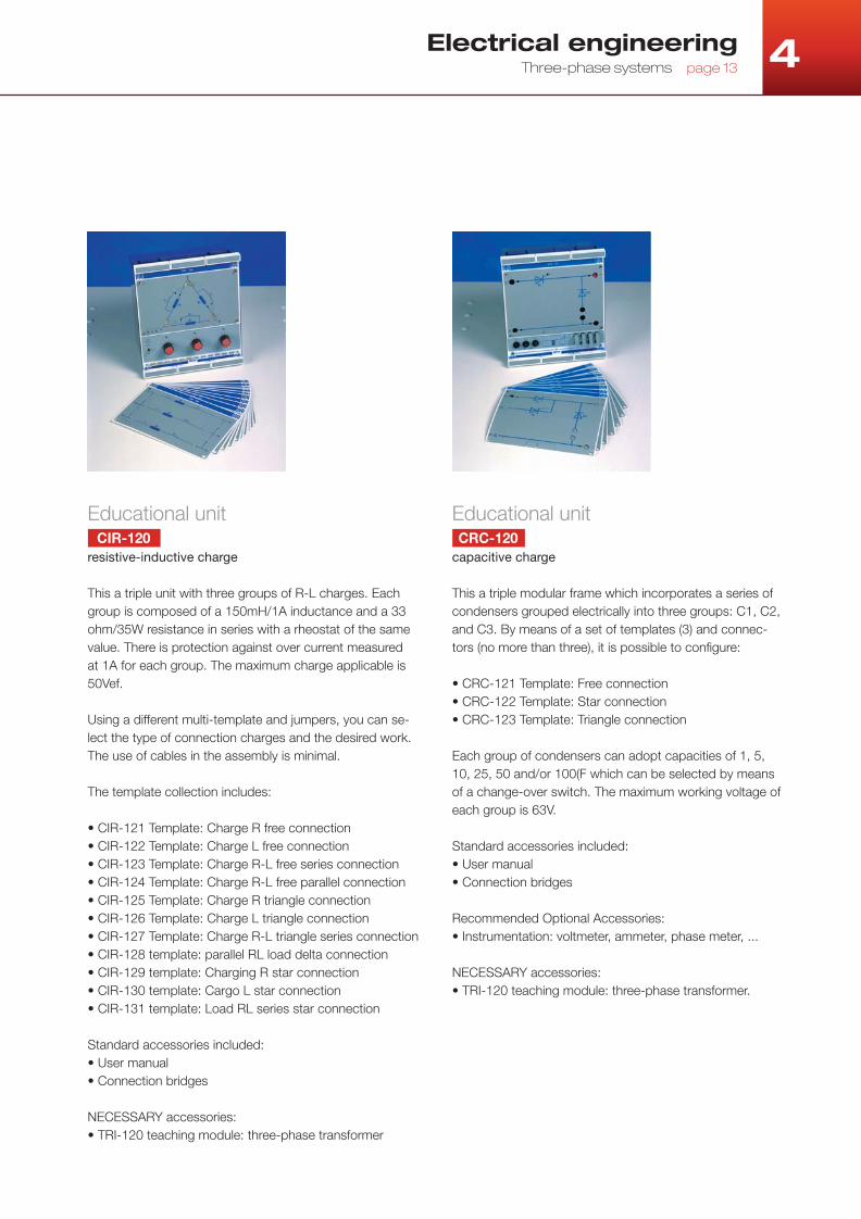
Teaching moduleAUT-120
single-phase autotransformer
Single-phase autotransformer with 230 V / 50-60 Hz
input voltage and variable output adjusted by a poten-
tiometer control.
• Maximum output voltage: 250 V
• Maximum output load: 1 A
• Protection: 1 A fuse
• Safety bushings
Standard accessories included:
• User manual
Electrical engineeringTransformation of electric current page 15
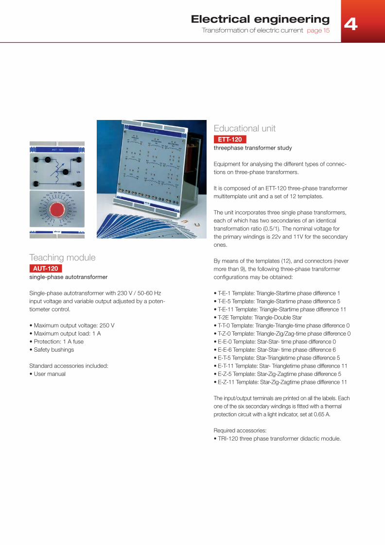
Educational unitETT-120
threephase transformer study
Equipment for analysing the different types of connec-
tions on three-phase transformers.
It is composed of an ETT-120 three-phase transformer
multitemplate unit and a set of 12 templates.
The unit incorporates three single phase transformers,
each of which has two secondaries of an identical
transformation ratio (0.5/1). The nominal voltage for
the primary windings is 22v and 11V for the secondary
ones.
By means of the templates (12), and connectors (never
more than 9), the following three-phase transformer
confi gurations may be obtained:
• T-E-1 Template: Triangle-Startime phase difference 1
• T-E-5 Template: Triangle-Startime phase difference 5
• T-E-11 Template: Triangle-Startime phase difference 11
• T-2E Template: Triangle-Double Star
• T-T-0 Template: Triangle-Triangle-time phase difference 0
• T-Z-0 Template: Triangle-Zig/Zag-time phase difference 0
• E-E-0 Template: Star-Star- time phase difference 0
• E-E-6 Template: Star-Star- time phase difference 6
• E-T-5 Template: Star-Triangletime phase difference 5
• E-T-11 Template: Star- Triangletime phase difference 11
• E-Z-5 Template: Star-Zig-Zagtime phase difference 5
• E-Z-11 Template: Star-Zig-Zagtime phase difference 11
The input/output terminals are printed on all the labels. Each
one of the six secondary windings is fi tted with a thermal
protection circuit with a light indicator, set at 0.65 A.
Required accessories:
• TRI-120 three phase transformer didactic module.
4 Electrical engineeringpage 16 Introduction to electric machinery
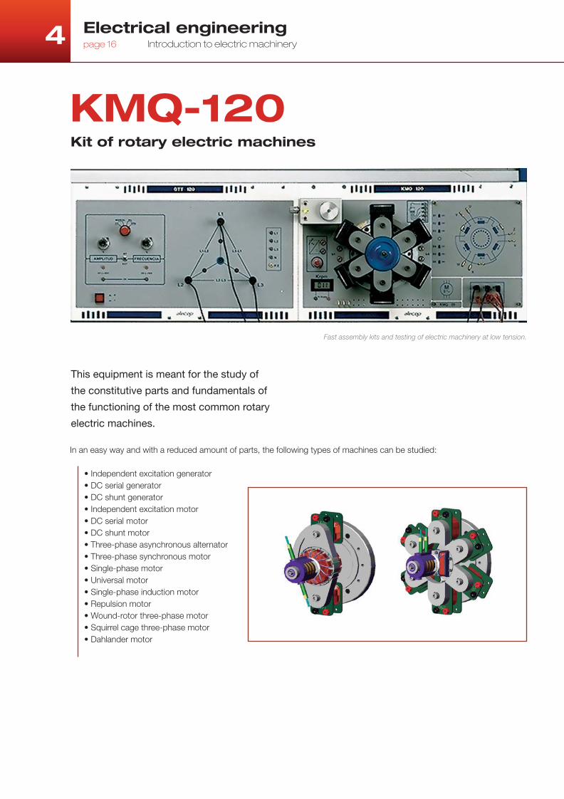
In an easy way and with a reduced amount of parts, the following types of machines can be studied:
• Independent excitation generator
• DC serial generator
• DC shunt generator
• Independent excitation motor
• DC serial motor
• DC shunt motor
• Three-phase asynchronous alternator
• Three-phase synchronous motor
• Single-phase motor
• Universal motor
• Single-phase induction motor
• Repulsion motor
• Wound-rotor three-phase motor
• Squirrel cage three-phase motor
• Dahlander motor
KMQ-120Kit of rotary electric machines
Fast assembly kits and testing of electric machinery at low tension.
This equipment is meant for the study of
the constitutive parts and fundamentals of
the functioning of the most common rotary
electric machines.

4 Electrical engineering Introduction to electric machinery page 17
this can be placed on the work surface or on a vertical
frame. The support disc is attached to the panel, being
used for screwing on the various fi eld poles. The shaft
protrudes from the centre of the disc and this is where the
different rotors are attached.
An area has been set aside on the upper left-hand corner
of the panel for the attachment of a drive motor that will
allow experiments to be conducted with generators or
provide a braking torque for the motors.
The right-hand side of the panel has the area for electric
connections, using interchangeable labels. These allow the
quick and clear interconnection of the various windings on
the rotary machine subject to the experiment, providing
the necessary information for its assembly. The areas the
label is subdivided into make it easy to distinguish the
electric connections both inside and outside the machine
(connection board), without losing the perspective of a real
machine.
The panel includes a 0-10 Vcc/2 A adjustable power
supply for the excitation of the machines, as well as a
tachometer for measuring the motor’s velocity during the
different types of tests.
The machines built are powered by a low voltage supply
- 22/38 V AC/DC -, which ensures the students’ safety.
Hence, there are available (depending on choice) a TRI-120
transformer or a GTT-120 three-phase generator.
It includes a series of parts (rotors, brush holders,
windings, polar parts, etc), which allow confi guring
different rotary machines on a panel in a fast and easy
way. The parts are the following:
• 1 Two-pole rotor
• 1 Three-pole rotor
• 1 Twelve-pole rotor
• 1 Squirrel cage rotor
• 1 Shaft
• 6 Narrow fi eld poles
• 3 Wide fi eld poles
• 6 Windings of 240 turns
• 4 Windings of 1400 turns
• 5 Brushes
• 1 Brush holder
• 6 Light poles
• 1 Drive motor with belts
• Tools and screws
This equipment consists in:
Panel
Power supply
Suitcase
Standard accessories included:
• Practical and user’s manual
• Connexion wires
Necessary accessories not included:
• Three-phase generator GTT-120, or as an alternative:
• Three-phase transformer TRI-120 + power supply 0-15 Vcc/5 A.

4 Electrical engineeringpage 18 Introduction to electric machinery
KMQ-100BASIC kit of rotary electric machines
This is a “reduced” version of the
dissectible machine, designed as
a student work station.
Although it has fewer options than the full kit, it may be a valid option, depending on the nature of the practical activities to be held. Basically, the differences are as follows:
The assembly panel is smaller and can only be placed on the tabletop. It does not include the drive motor, tachometer, power source or connexions area neither. In this way, the result is a compact assembly panel.
The set of machinery construction, which is more reduced, fi ts in a suitcase that contains the following:
• 6 Windings of 250 turns• 2 Windings of 1400 turns• 1 Twelve-pole rotor• 1 Squirrel cage rotor• 1 Brush holder• 5 Brushes• 2 Wide fi eld poles• 6 Narrow fi eld poles• 1 assembly support base• 1 assembly shaft
Standard accessories included:
• Practical and user’s manual
• Connexion wires
Necessary accessories not included:
• Three-phase generator GTT-120, or as an alternative:
• Three-phase transformer TRI-120 + power supply 0-15 Vcc/5 A.
4 Electrical engineering Introduction to electric machinery page 19
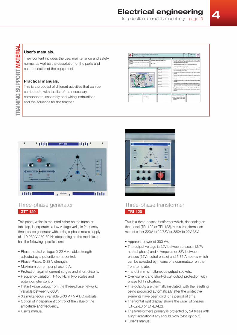
Three-phase generatorGTT-120
This panel, which is mounted either on the frame or
tabletop, incorporates a low voltage variable frequency
three-phase generator with a single-phase mains supply
of 110-230 V / 50-60 Hz (depending on the module). It
has the following specifi cations:
• Phase-neutral voltage: 0-22 V variable strength
adjusted by a potentiometer control.
• Phase-Phase: 0-38 V strength.
• Maximum current per phase: 5 A.
• Protection against current surges and short circuits.
• Frequency variation: 1-100 Hz in two scales and
potentiometer control.
• Instant value output from the three-phase network,
variable between 0-360º.
• 3 simultaneously variable 0-30 V / 5 A DC outputs
• Option of independent control of the value of the
amplitude and frequency.
• User’s manual.
Three-phase transformerTRI-120
This is a three-phase transformer which, depending on
the model (TRI-122 or TRI-123), has a transformation
ratio of either 220V to 22/38V or 380V to 22V-38V.
• Apparent power of 300 VA.
• The output voltage is 22V between phases (12.7V
neutral phase) and 4 Amperes or 38V between
phases (22V neutral phase) and 3.75 Amperes which
can be selected by means of a commutator on the
front template.
• 4 and 2 mm simultaneous output sockets.
• Over-current and short-circuit output protection with
phase light indicators.
• The outputs are thermally insulated, with the resetting
being produced automatically after the protective
elements have been cold for a period of time.
• The frontal light display shows the order of phases
(L1-L2-L3 or L1-L3-L2).
• The transformer’s primary is protected by 2A fuses with
a light indication if any should blow (pilot light out).
• User’s manual.
TRAI
NIN
G S
UPPO
RT M
ATER
IAL
User’s manuals.
Their content includes the use, maintenance and safety
norms, as well as the description of the parts and
characteristics of the equipment.
Practical manuals.
This is a proposal of different activities that can be
carried out , with the list of the necessary
components, assembly and wiring instructions
and the solutions for the teacher.

alecop.com
Apdo. 81, Loramendi 11
20500 Arrasate-Mondragón
Gipuzkoa (España)
Tel: +34 943 71 24 05
Fax: +34 943 79 92 12
Alecop Didactic International
P.B. No. 6488
Dubai
United Arab Emirates.
Tel: +971 4-3242131
Fax: +971 4-3242500
www.alecopdi.com