
PRESENTATION - Migrating AWS EBS backed AMI's between Regions
6LA7
4-1
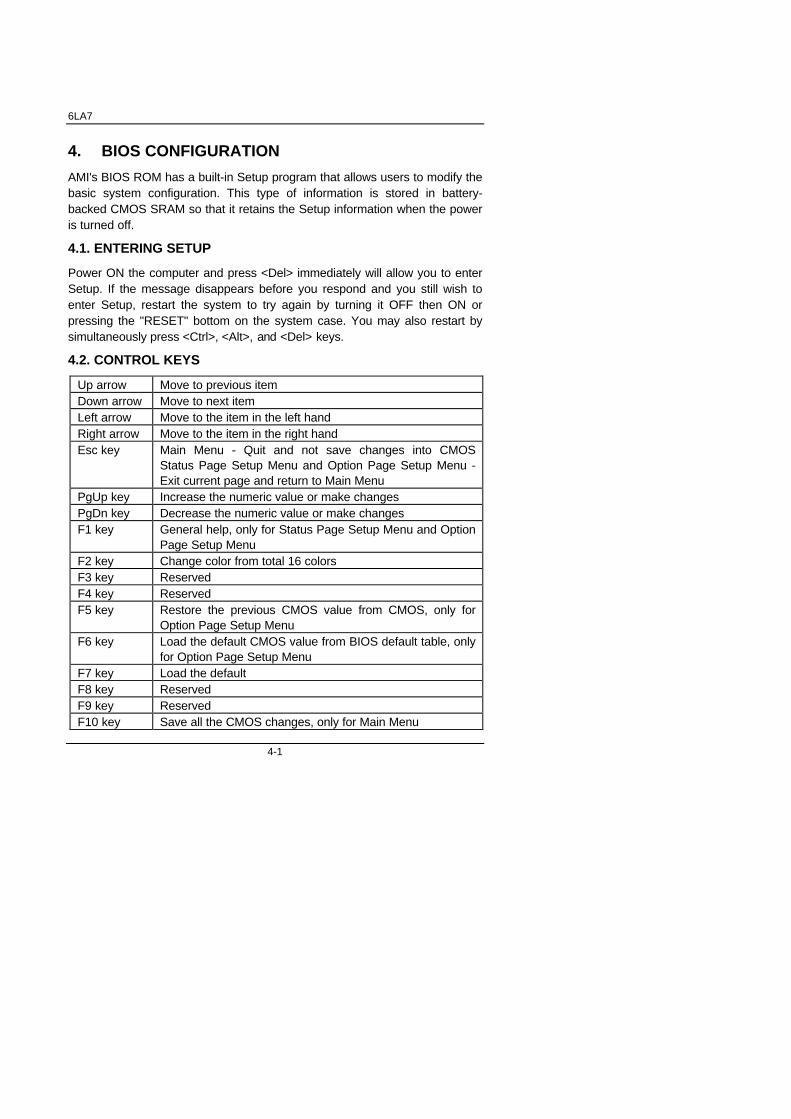
4. BIOS CONFIGURATION
AMI's BIOS ROM has a built-in Setup program that allows users to modify thebasic system configuration. This type of information is stored in battery-backed CMOS SRAM so that it retains the Setup information when the poweris turned off.
4.1. ENTERING SETUP
Power ON the computer and press <Del> immediately will allow you to enterSetup. If the message disappears before you respond and you still wish toenter Setup, restart the system to try again by turning it OFF then ON orpressing the "RESET" bottom on the system case. You may also restart bysimultaneously press <Ctrl>, <Alt>, and <Del> keys.
4.2. CONTROL KEYS
Up arrow Move to previous itemDown arrow Move to next itemLeft arrow Move to the item in the left handRight arrow Move to the item in the right handEsc key Main Menu - Quit and not save changes into CMOS
Status Page Setup Menu and Option Page Setup Menu -Exit current page and return to Main Menu
PgUp key Increase the numeric value or make changesPgDn key Decrease the numeric value or make changesF1 key General help, only for Status Page Setup Menu and Option
Page Setup MenuF2 key Change color from total 16 colorsF3 key ReservedF4 key ReservedF5 key Restore the previous CMOS value from CMOS, only for
Option Page Setup MenuF6 key Load the default CMOS value from BIOS default table, only
for Option Page Setup MenuF7 key Load the defaultF8 key ReservedF9 key ReservedF10 key Save all the CMOS changes, only for Main Menu

BIOS Configuration
4-2
4.3. GETTING HELP
4.3.1. Main Menu
The on-line description of the highlighted setup function is displayed at thebottom of the screen.
4.3.2. Status Page Setup Menu / Option Page Setup Menu
Press F1 to pop up a small help window that describes the appropriate keysto use and the possible selections for the highlighted item. To exit the HelpWindow press <Esc>.
4.4. THE MAIN MENU
Once you enter AMI BIOS CMOS Setup Utility, the Main Menu (Figure 4.1)will appear on the screen. The Main Menu allows you to select from ninesetup functions and two exit choices. Use arrow keys to select among theitems and press <Enter> to accept or enter the sub-menu.
Figure 4.1: Main Menu• Standard CMOS setup
This setup page includes all the items in standard compatible BIOS.
• BIOS features setup
This setup page includes all the items of AMI special enhancedfeatures.

6LA7
4-3
• Chipset features setup
This setup page includes all the items of chipset special features.
• Power management setup
This setup page includes all the items of Green function features.
• PNP/PCI configuration
This setup page includes all the configurations of PCI & PnP ISAresources.
• Load bios defaults
Bios Defaults indicates the value of the system parameter which thesystem would be in the safe configuration.
• Load setup defaults
Setup Defaults indicates the value of the system parameter which thesystem would be in the most appropriate configuration.
• Integrated peripherals
This setup page includes all onboard peripherals.
• Hardware Monitor Setup
This setup page is auto detect fan and temperature status.
• Supervisor password
Change, set, or disable password. It allows you to limit access to thesystem and Setup, or just to Setup.
• User password
Change, set, or disable password. It allows you to limit access to thesystem.
• IDE HDD auto detection
Automatically configure hard disk parameters.
• Save & exit setup
Save CMOS value settings to CMOS and exit setup.
• Exit without saving
Abandon all CMOS value changes and exit setup.

BIOS Configuration
4-4
4.5. STANDARD CMOS SETUP MENU
The items in Standard CMOS Setup Menu (Figure 4.2) are divided into 9categories. Each category includes no, one or more than one setup items.Use the arrows to highlight the item and then use the <PgUp> or <PgDn>keys to select the value you want in each item.
Figure 4.2: Standard CMOS Setup Menu• Date
The date format is <day>, <month> <date> <year>.
day The day, from Sun to Sat, determined by the BIOS and isdisplay-only
month The month, Jan. through Dec.date The date, from 1 to 31 (or the maximum allowed in the
month)year The year, from 1994 through 2079
• Time
The times format in <hour> <minute> <second>. The time is calculatedbase on the 24-hour military-time clock. For example, 1 p.m. is 13:00:00.

6LA7
4-5
• Primary HDDs / Secondary HDDs
The category identifies the types of hard disk from drive C to F that hasbeen installed in the computer. There are two types: auto type, and userdefinable type. User type is user-definable; Auto type which willautomatically detect HDD type.
Note that the specifications of your drive must match with the drive table.The hard disk will not work properly if you enter improper information forthis category.
If you select User Type, related information will be asked to enter to thefollowing items. Enter the information directly from the keyboard andpress <Enter>. Such information should be provided in the documentationform your hard disk vendor or the system manufacturer.
CYLS. Number of cylindersHEADS number of headsPRECOMP write precompLANDZONE Landing zoneSECTORS number of sectors
If a hard disk has not been installed select NONE and press <Enter>.
• Floppy Drive A / Floppy Drive B
The category identifies the types of floppy disk drive A or drive B that hasbeen installed in the computer.
None No floppy drive installed360K, 5.25 in. 5.25 inch PC-type standard drive; 360K byte capacity.1.2M, 5.25 in. 5.25 inch AT-type high-density drive; 1.2M byte
capacity (3.5 inch when 3 Mode is Enabled).720K, 3.5 in. 3.5 inch double-sided drive; 720K byte capacity1.44M, 3.5 in. 3.5 inch double-sided drive; 1.44M byte capacity.2.88M, 3.5 in. 3.5 inch double-sided drive; 2.88M byte capacity.

BIOS Configuration
4-6
• Boot Sector Virus Protection
If it is set to enable, the category will flash on the screen when there isany attempt to write to the boot sector or partition table of the hard diskdrive. The system will halt and the following error message will appear inthe mean time. You can run anti-virus program to locate the problem.
Default value is Disabled.
Enabled Activate automatically when the system boots up causing awarning message to appear when anything attempts toaccess the boot sector or hard disk partition table
Disabled No warning message to appear when anything attempts toaccess the boot sector or hard disk partition table
• Memory
The category is display-only which is determined by POST (Power OnSelf Test) of the BIOS.
Base Memory
The POST of the BIOS will determine the amount of base (orconventional) memory installed in the system.
The value of the base memory is typically 512 K for systemswith 512 K memory installed on the motherboard, or 640 K forsystems with 640 K or more memory installed on themotherboard.
Extended Memory
The BIOS determines how much extended memory is presentduring the POST.
This is the amount of memory located above 1 MB in the CPU'smemory address map.

6LA7
4-7
Expanded Memory
Expanded Memory in memory defined by theLotus/Intel/Microsoft (LIM) standard as EMS.Many standard DOS applications can not utilize memory above640 K; the Expanded Memory Specification (EMS) swapsmemory, which not utilized by DOS with a section, or frame, sothese applications, can access all of the system memory.
Memory can be swapped by EMS is usually 64 K within 1 MB ormemory above 1 MB, depends on the chipset design.
Expanded memory device driver is required to use memory asExpanded Memory.
Other Memory
This refers to the memory located in the 640 K to 1024 Kaddress space. This is memory that can be used for differentapplications.
DOS uses this area to load device drivers to keep as much basememory free for application programs. Most use for this area isShadow RAM.

BIOS Configuration
4-8
4.6. BIOS FEATURES SETUP
Figure 4.3: BIOS Features Setup
• Quick Boot
The default value is Disabled.
Enabled Enabled Quick Boot Function.
Disabled Disabled Quick Boot Function.
• 1st / 2nd / 3rd Boot Device
The default value is Floppy or LS-120 / ATAPI ZIP or CDROM or SCSI orNET WORK / I20 or IDE-0~IDE-3 or Disabled.
Floppy Boot Device by Floppy.
LS-120 / ATAPI ZIP Boot Device by LS-120 / ATAPI ZIP.
CDROM Boot Device by CDROM.
SCSI Boot Device by SCSI.
NET WORK Boot Device by NET WORK.
IDE-0~IDE-3 Boot Device by IDE-0~IDE-3.
Disabled Boot Device by Disabled.
I20 Boot Device by I20.

6LA7
4-9
• Floppy Access Control
The default value is Read-Write.
Read-Write Set Floppy Access Control : Read-Write.
Read-Only Set Floppy Access Control : Read Only.
• HDD Access Control
The default value is Read-Write.
Read-Write Set HDD Access Control : Read-Write.
Read-Only Set HDD Access Control : Read Only.
• S.M.A.R.T. Hard Disks
The default value is Disable.
Enable Enable S.M.A.R.T. Hard Disks
Disable Disable S.M.A.R.T. Hard Disks
• Boot Up Num-Lock
The default value is On.
On Keypad is number keysOff Keypad is arrow keys
• Floppy Drive Swap
The default value is Disabled.
Enabled Floppy A & B will be swapped under DOSDisabled Floppy A & B will be normal definition
BIOS Configuration
4-10
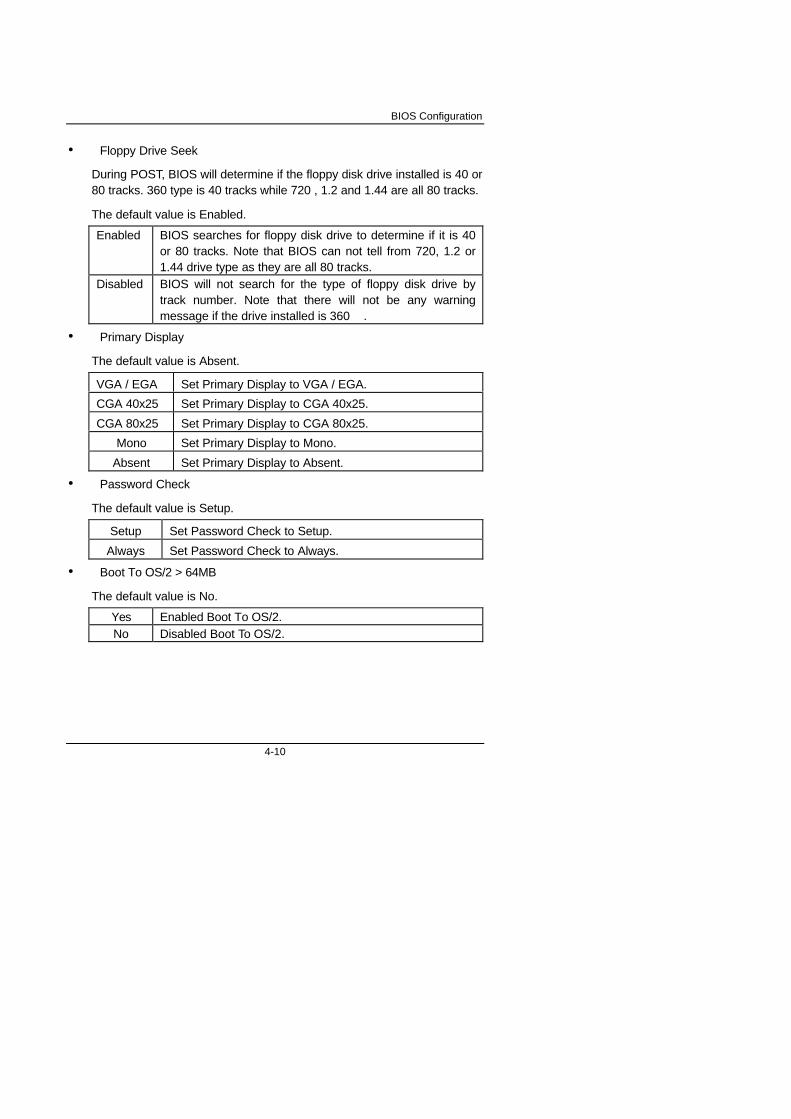
• Floppy Drive Seek
During POST, BIOS will determine if the floppy disk drive installed is 40 or80 tracks. 360 type is 40 tracks while 720 , 1.2 and 1.44 are all 80 tracks.
The default value is Enabled.
Enabled BIOS searches for floppy disk drive to determine if it is 40or 80 tracks. Note that BIOS can not tell from 720, 1.2 or1.44 drive type as they are all 80 tracks.
Disabled BIOS will not search for the type of floppy disk drive bytrack number. Note that there will not be any warningmessage if the drive installed is 360 .
• Primary Display
The default value is Absent.
VGA / EGA Set Primary Display to VGA / EGA.
CGA 40x25 Set Primary Display to CGA 40x25.
CGA 80x25 Set Primary Display to CGA 80x25.
Mono Set Primary Display to Mono.
Absent Set Primary Display to Absent.
• Password Check
The default value is Setup.
Setup Set Password Check to Setup.
Always Set Password Check to Always.
• Boot To OS/2 > 64MB
The default value is No.
Yes Enabled Boot To OS/2.No Disabled Boot To OS/2.

6LA7
4-11
• CPU MicroCode Updation
The default value is Enabled.
Enabled Enabled CPU Update Data.Disabled Disabled CPU Update Data.
• Internal Cache / External Cache
These two categories speed up memory access. However, it depends onCPU / chipset design. The default value is Enabled.
Enabled Enable cacheDisabled Disable cache
• Cache Bus ECC
The default value is Enabled.
Enabled Enable Cache Bus ECCDisabled Disable Cache Bus ECC
• System BIOS Cacheable
The default value is Enabled.
Enabled Enabled System BIOS Cacheable.Disabled Disabled System BIOS Cacheable.
• Video BIOS Shadow
It determines whether video BIOS is able to copy to RAM, however, it isoptional from chipset design. Video Shadow will increase the videospeed. The default value is Enabled.
Enabled Video shadow is enabledDisabled Video shadow is disabled

BIOS Configuration
4-12
4.7. CHIPSET FEATURES SETUP
Figure 4.4: Chipset Features Setup
• Auto Detect DIMM Clock
The default value is Enabled
Disabled Auto Detect DIMM Clock function Disabled.Enabled Auto Detect DIMM Clock function Enabled.
• SDRAM RAS-to-CAS Delay
The default value is Fast
Slow For 67 / 83 MHz SDRAM DIMM module.Fast For 100 MHz SDRAM DIMM module.
• SDRAM CAS Latency
The default value is Auto
Auto Set SDRAM CAS Latency to Auto.
3 Clks For 67 / 83 MHz SDRAM DIMM module.
2 Clks For 100 MHz SDRAM DIMM module.

6LA7
4-13
• SDRAM RAS Precharge Time
The default value is Fast.
Slow For 67 / 83 MHz SDRAM DIMM module.
Fast For 100 MHz SDRAM DIMM module.
• DRAM Data Integrity Mode
The default value is Non-ECC.
Non-ECC For 64bit standard type DIMM module.ECC For 72bit ECC type DIMM module.
• Fixed Memory Hole
The default value is Disabled.
512KB-640KB Set Address=512-640KB remap to ISA BUS.15MB-16MB Set Address=15~16MB remap to ISA BUS.
Disabled Normal Setting.
• Delayed Transaction
The default value is Disabled.
Disabled Normal operation.Enabled For slow speed ISA device in system.
• USB K/B Legacy Support.
The default value is Disabled.
Enabled Enabled USB K/B Legacy Support Function.
Disabled Disabled USB K/B Legacy Support Function.

BIOS Configuration
4-14
4.8. POWER MANAGEMENT SETUP
Figure 4.5: Power Management Setup
• Power Management / APM
The default value is Enabled.
Enabled Enable Green & software APM function.Disabled Disable Green & software APM function.
• Power LED in Suspend Mode
The default value is Blinking.
Blinking Set Power LED in Suspend at Blinking mode.
ON Set Power LED in Suspend at ON mode.
Off/Dual Set Power LED in Suspend at Off/Dual mode.
• Video Power Down
The default value is Suspend.
Disabled Disabled Video Power Down Mode Function.
Suspend Set Video Power Down Mode to Suspend.
6LA7
4-15
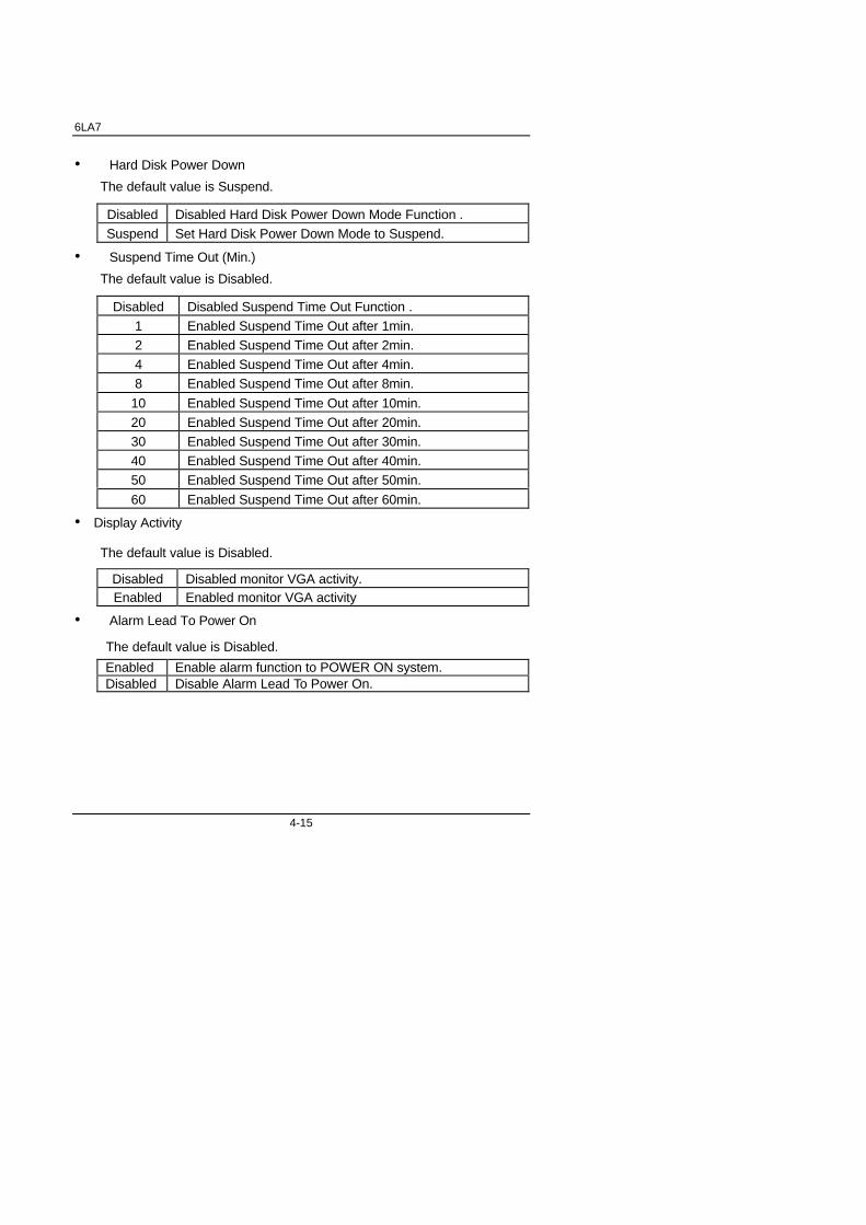
• Hard Disk Power Down
The default value is Suspend.
Disabled Disabled Hard Disk Power Down Mode Function .
Suspend Set Hard Disk Power Down Mode to Suspend.
• Suspend Time Out (Min.)
The default value is Disabled.
Disabled Disabled Suspend Time Out Function .
1 Enabled Suspend Time Out after 1min.
2 Enabled Suspend Time Out after 2min.
4 Enabled Suspend Time Out after 4min.
8 Enabled Suspend Time Out after 8min.
10 Enabled Suspend Time Out after 10min.
20 Enabled Suspend Time Out after 20min.
30 Enabled Suspend Time Out after 30min.
40 Enabled Suspend Time Out after 40min.
50 Enabled Suspend Time Out after 50min.
60 Enabled Suspend Time Out after 60min.
• Display Activity
The default value is Disabled.
Disabled Disabled monitor VGA activity.Enabled Enabled monitor VGA activity
• Alarm Lead To Power On
The default value is Disabled.
Enabled Enable alarm function to POWER ON system.Disabled Disable Alarm Lead To Power On.

BIOS Configuration
4-16
If RTC Alarm Lead To Power On is Enabled.
Alarm Date : Disabled,1~31 Alarm Hour: 0~23 Alarm Minute : 0~59 Alarm Second : 0~59
• Serial Port1
The default value is Enabled.
Disabled Disable this function.
Enabled Enable monitor Serial Port for Green event.
• Serial Port2
The default value is Enabled.
Disabled Disable this function.
Enabled Enable monitor Serial Port for Green event.
• Parallel Port
The default value is Enabled
Disabled Disable this function.
Enabled Enable monitor Parallel Port for Green event.
• Floppy Disk
The default value is Disabled.
Disabled Disable this function.Enabled Enable monitor Floppy Disk for Green event.
• Primary Master IDE
The default value is Enabled.
Disabled Disable this function.Enabled Enable monitor Primary IDE for Green event.

6LA7
4-17
• Primary slave IDE
The default value is Disabled.
Disabled Disable this function.Enabled Enable monitor slave IDE for Green event.
• Secondary Master IDE
The default value is Enabled.
Disabled Disable this function.Enabled Enable monitor Secondary Master IDE for Green event.
• Secondary slave IDE
The default value is Disabled.
Disabled Disable this function.Enabled Enable monitor Secondary slave IDE for Green event.
• CPUFAN Off In Suspend
The default value is Enabled.
Disabled Disable this function.Enabled Stop CPU FAN when entering Suspend mode.
• PME Lead To Power On
The default value is Disabled.
Disabled Disable this function.Enabled Enable PME Lead To Power On.
• Ring On Lead To Power On
The default value is Enabled.
Disabled Disable this function.Enabled Enable Modem ring on / Wake on Lan function.

BIOS Configuration
4-18
• Power Button Function
The default value is Instand-Off.
Instand-Off Soft switch ON/OFF for POWER ON/OFF.Delay 4 Sec. Soft switch ON 4sec. for POWER OFF.
4.9. PNP/PCI CONFIGURATION
Figure 4.6: PCI Slot Configuration
• Plug and Play Aware O/S
The default value is No.
Yes Enable Plug and Play Aware O/S function.No Disable Plug and Play Aware O/S function.
• Reset Configuration Data
The default value is No.
No Disable this function.YES Enable clear PnP information in ESCD.
6LA7
4-19
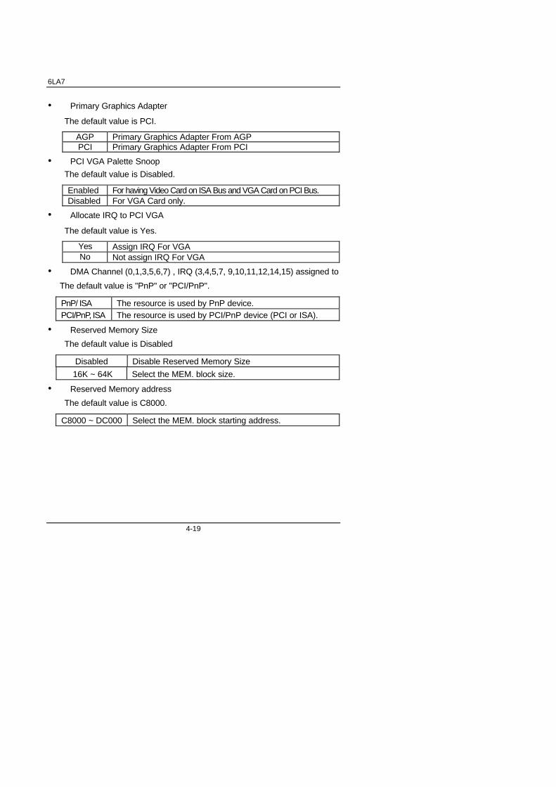
• Primary Graphics Adapter
The default value is PCI.
AGP Primary Graphics Adapter From AGPPCI Primary Graphics Adapter From PCI
• PCI VGA Palette Snoop
The default value is Disabled.
Enabled For having Video Card on ISA Bus and VGA Card on PCI Bus.Disabled For VGA Card only.
• Allocate IRQ to PCI VGA
The default value is Yes.
Yes Assign IRQ For VGANo Not assign IRQ For VGA
• DMA Channel (0,1,3,5,6,7) , IRQ (3,4,5,7, 9,10,11,12,14,15) assigned to
The default value is "PnP" or "PCI/PnP".
PnP/ ISA The resource is used by PnP device.PCI/PnP, ISA The resource is used by PCI/PnP device (PCI or ISA).
• Reserved Memory Size
The default value is Disabled
Disabled Disable Reserved Memory Size
16K ~ 64K Select the MEM. block size.
• Reserved Memory address
The default value is C8000.
C8000 ~ DC000 Select the MEM. block starting address.

BIOS Configuration
4-20
4.10. LOAD BIOS DEFAULTS
Figure 4.7: Load Bios Defaults
• Load BIOS Defaults
To load BIOS defaults value to CMOS SRAM, enter "Y". If not, enter "N".
6LA7
4-21
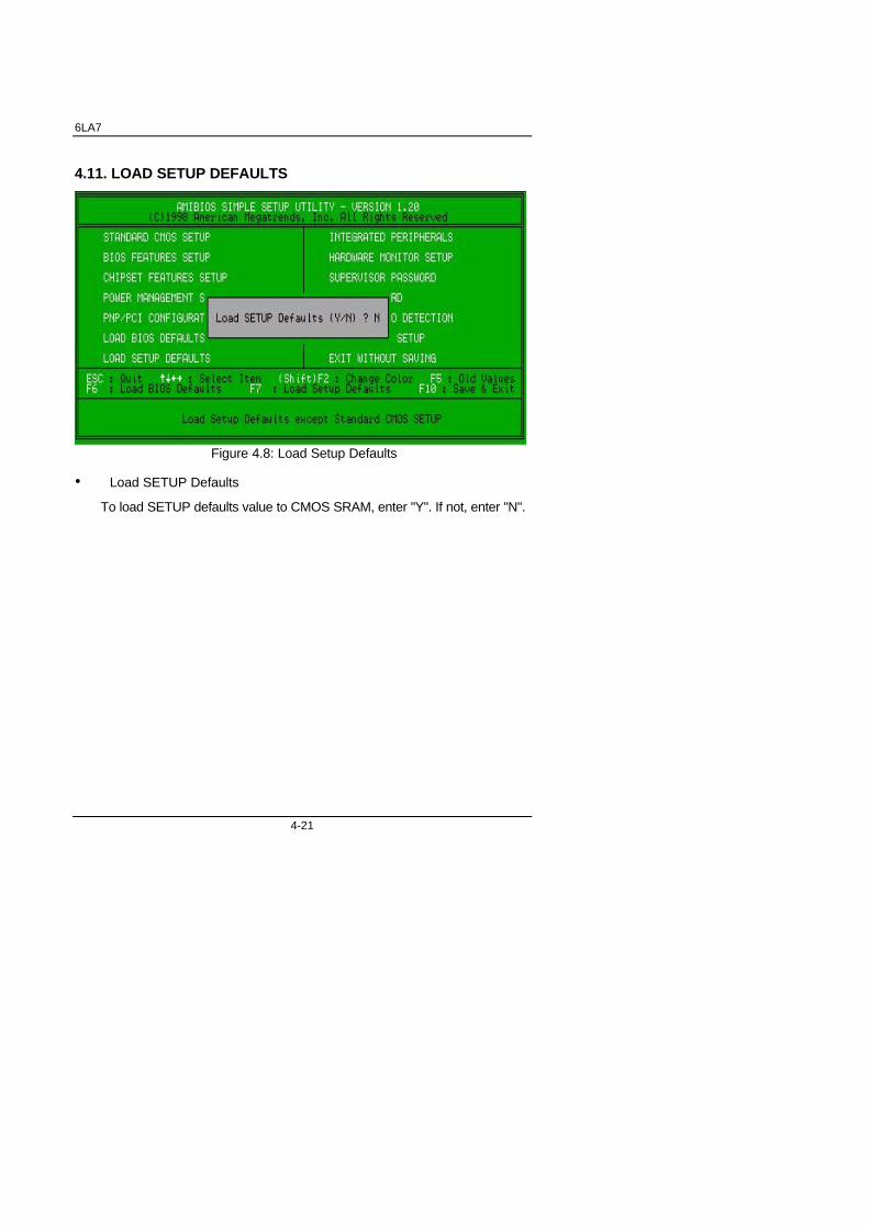
4.11. LOAD SETUP DEFAULTS
Figure 4.8: Load Setup Defaults
• Load SETUP Defaults
To load SETUP defaults value to CMOS SRAM, enter "Y". If not, enter "N".
BIOS Configuration
4-22
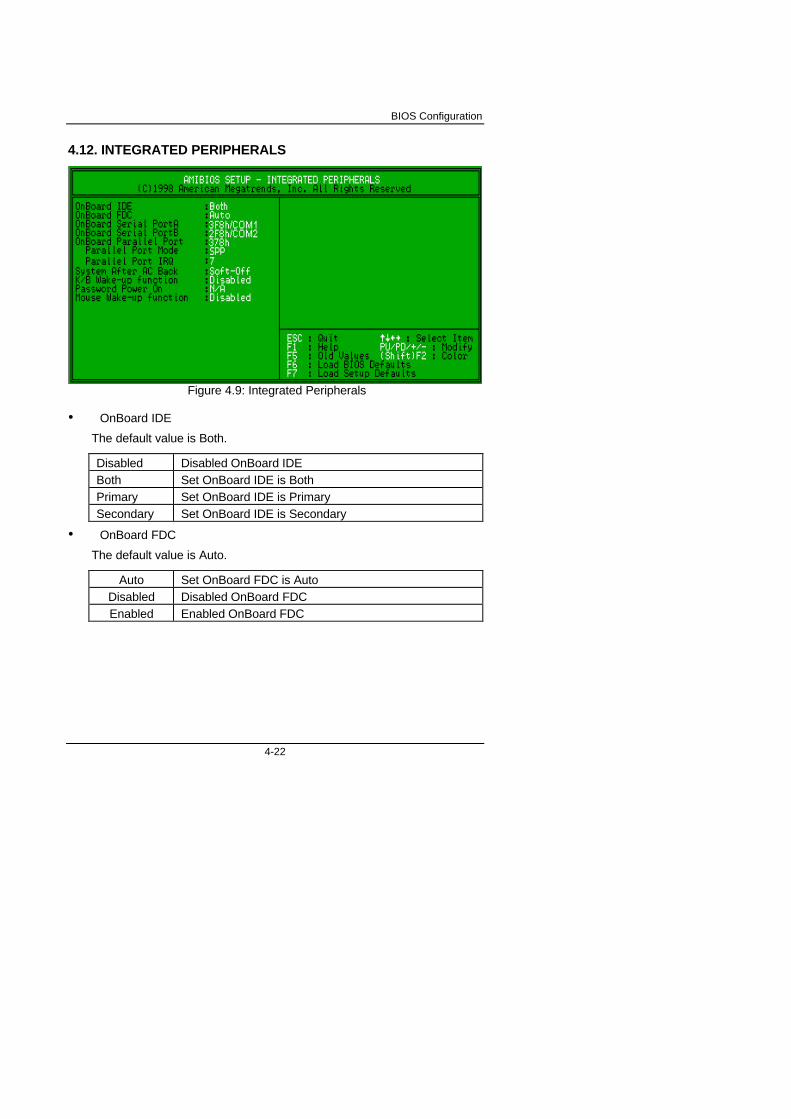
4.12. INTEGRATED PERIPHERALS
Figure 4.9: Integrated Peripherals
• OnBoard IDE
The default value is Both.
Disabled Disabled OnBoard IDEBoth Set OnBoard IDE is BothPrimary Set OnBoard IDE is PrimarySecondary Set OnBoard IDE is Secondary
• OnBoard FDC
The default value is Auto.
Auto Set OnBoard FDC is AutoDisabled Disabled OnBoard FDCEnabled Enabled OnBoard FDC

6LA7
4-23
• OnBoard Serial Port A
The default value is 3F8h/COM1.
Auto BIOS will automatically setup the port A address.3F8h/COM1 Enable onBoard Serial port A and address is 3F8h.2F8h/COM2 Enable onBoard Serial port A and address is 2F8h.3E8h/COM3 Enable onBoard Serial port A and address is 3E8h.2E8h/COM4 Enable onBoard Serial port A and address is 2E8h.Disabled Disable onBoard Serial port A.
• OnBoard Serial Port B
The default value is 2F8h/COM2.
Auto BIOS will automatically setup the port B address.
3F8h/COM1 Enable OnBoard Serial port B and address is 3F8h.
2F8h/COM2 Enable OnBoard Serial port B and address is 2F8h.
3E8h/COM3 Enable OnBoard Serial port B and address is 3E8h.
2E8h/COM4 Enable OnBoard Serial port B and address is 2E8h.
Disabled Disable OnBoard Serial port B.
• OnBoard Parallel port
The default value is 378h.
378h Enable OnBoard LPT port and address is 378h.
278h Enable OnBoard LPT port and address is 278h.
3BCh Enable OnBoard LPT port and address is 3BCh.
Auto Set OnBoard LPT port is Auto.
Disabled Disable OnBoard LPT port.
• Parallel Port Mode
The default value is SPP.
N/A Disabled this function.
SPP Using Parallel port as Standard Printer Port.
EPP Using Parallel port as Enhanced Parallel Port.
ECP Using Parallel port as Extended Capabilities Port.
ECP+EPP Using Parallel port as ECP & EPP mode.

BIOS Configuration
4-24
• Parallel Port IRQ
The default value is 7.
N/A Disabled this function.
Auto Set Parallel Port IRQ to Auto.
7 Set Parallel Port IRQ to 7.
5 Set Parallel Port IRQ to 5.
• System After AC Back
The default value is Soft-Off.
Memory This function depends on computer status
Soft-Off Set System Soft-Off Status.
Full-On Set System Full-On Status.
• K/B Wake-up function
The default value is Disabled.
Disabled Disable this function.
Multikey Enter multikey combination to Power on system.
Power Key If your keyboard have “Power Key” button, you canpress the key to power on your system.
• Password Power On
The default value is N/A.
N/A Disable this function.
Enter Enter from 1 to 5 characters to set the Keyboard PowerOn Password.
• Mouse Wake-up function
The default value is Disabled.
Disabled Disable this function.
Left Double Double Click on PS/2 mouse left button to Power onsystem.
Right Double Double Click on PS/2 mouse right button to Power onsystem.

6LA7
4-25
4.13 HARDWARE MONITOR
Figure 4.10: Hardware Monitor Setup
• Shutdown Temp. (°C / °F)
(This function will be effective only for the operating systems that supportACPI Function.)
The default value is 75°C / 167°F
Disabled Normal Operation60°C / 140°F Monitor CPU Temp. at 60°C / 140°F, if Temp. > 60°C /
140°F system will automatically power off .65°C / 149°F Monitor CPU Temp. at 65°C / 149°F, if Temp. > 65°C /
149°F system will automatically power off .70°C / 158°F Monitor CPU Temp. at 70°C / 158°F, if Temp. > 70°C /
158°F system will automatically power off .75°C / 167°F Monitor CPU Temp. at 75°C / 167°F, if Temp. > 75°C /
167°F system will automatically power off .
BIOS Configuration
4-26
• CPU Temperature Alarm. (°C / °F)
The default value is 70°C /158°F
Disabled Normal Operation65°C / 149°F Monitor CPU Warning Temp. at 65°C / 149°F70°C / 158°F Monitor CPU Warning Temp. at 70°C / 158°F75°C / 167°F Monitor CPU Warning Temp. at 75°C / 167°F80°C / 176°F Monitor CPU Warning Temp. at 80°C / 176°F85°C / 185°F Monitor CPU Warning Temp. at 85°C / 185°F90°C / 194°F Monitor CPU Warning Temp. at 90°C / 194°F95°C / 203°F Monitor CPU Warning Temp. at 95°C / 203°F
• CPU Fan Fail Alarm
No CPU Fan Fail Alarm Function Disabled.Yes CPU Fan Fail Alarm Function Enabled.
• Power Fan Fail Alarm
No Power Fan Fail Alarm Function Disabled.Yes Power Fan Fail Alarm Function Enabled.
• System Fan Fail Alarm
No System Fan Fail Alarm Function Disabled.Yes System Fan Fail Alarm Function Enabled.
• Reset Case Open Status
If the case is closed, “Case Opened” will show “No”.If the case have been opened, “Case Opened” will show “Yes” .If you want to reset “Case Opened” value, set “Reset Case Open Status”to “Yes” and save CMOS, your computer will restart.
• Current CPU Temperature (°C / °F)
Detect CPU Temperature automatically.
• Current CPU FAN Speed
Detect CPU Fan speed status automatically .
6LA7
4-27
• Current Power FAN Speed
Detect Power Fan speed status automatically .
• Current Panel FAN Speed
Detect Panel Fan speed status automatically .
• Current Voltage (v) VCORE / Vtt / Vcc3 / ±12V / ±5V /VBAT /5VSB
Detect system’ s voltage status automatically.
• Case Status
Opened Case status is on opened mode.Closed Case status is on closed mode.

BIOS Configuration
4-28
4.14. SUPERVISOR / USER PASSWORD
When you select this function, the following message will appear at the centerof the screen to assist you in creating a password.
Figure 4.11: Password Setting
Type the password, up to eight characters, and press <Enter>. The passwordtyped now will clear the previously entered password from CMOS memory.You will be asked to confirm the password. Type the password again andpress <Enter>.
To disable password, just press <Enter> when you are prompted to enterpassword. A message “PASSWORD DISABLED” will appear to confirm thepassword being disabled. Once the password is disabled, the system will bootand you can enter Setup freely.
If you select System at Security Option in BIOS Features Setup Menu, youwill be prompted for the password every time the system is rebooted or anytime you try to enter Setup Menu. If you select Setup at Security Option inBIOS Features Setup Menu, you will be prompted only when you try to enterSetup.

6LA7
4-29
4.15. IDE HDD AUTO DETECTION
Figure 4.12: IDE HDD Auto Detection
Type "Y" will accept the H.D.D. parameter reported by BIOS.
Type "N" will keep the old H.D.D. parameter setup. If the hard disk cylindernumber is over 1024, then the user can select LBA mode or LARGER modefor DOS partition larger than 528 MB.

BIOS Configuration
4-30
4.16. SAVE & EXIT SETUP
Figure 4.13: Save & Exit Setup
Type "Y" will quit the Setup Utility and save the user setup value to RTCCMOS SRAM.
Type "N" will return to Setup Utility.

6LA7
4-31
4.17. EXIT WITHOUT SAVING
Figure 4.14: Exit Without Saving
Type "Y" will quit the Setup Utility without saving to RTC CMOS SRAM.
Type "N" will return to Setup Utility.

FCC Compliance Statement:
This equipment has been tested and found tocomply with limits for a Class B digital device ,pursuant to Part 15 of the FCC rules. Theselimits are designed to provide reasonableprotection against harmful interference inresidential installations. This equipmentgenerates, uses, and can radiate radiofrequency energy, and if not installed and usedin accordance with the instructions, may causeharmful interference to radio communications.However, there is no guarantee thatinterference will not occur in a particularinstallation. If this equipment does cause
interference to radio or television equipment reception, which can bedetermined by turning the equipment off and on, the user is encouraged to tryto correct the interference by one or more of the following measures:
-Reorient or relocate the receiving antenna
-Move the equipment away from the receiver
-Plug the equipment into an outlet on a circuit different from that to whichthe receiver is connected
-Consult the dealer or an experienced radio/television technician foradditional suggestions
You are cautioned that any change or modifications to the equipment notexpressly approve by the party responsible for compliance could void Yourauthority to operate such equipment.
This device complies with Part 15 of the FCC Rules. Operation is subjected tothe following two conditions 1) this device may not cause harmful interferenceand 2) this device must accept any interference received, includinginterference that may cause undesired operation.
DECLARATION OF CONFORMITYPer FCC Part 2 Section 2. 1077(a)
Responsible Party Name: G.B.T. INC.
Address: 18305 Valley Blvd., Suite#A
LA Puent, CA 91744
Phone/Fax No: (818) 854-9338/ (818) 854-9339
hereby declares that the product
Product Name:
Model Number:
Mother Board
Conforms to the following specifications:
FCC Part 15, Subpart B, Section 15.107(a) and Section 15.109(a),Class B Digital Device
Supplementary Information:
This device complies with part 15 of the FCC Rules. Operation is subject to thefollowing two conditions: (1) This device may not cause harmful interference,and (2) this device must accept any inference received, including interferencethat may cause undesired operation.
Representative Person's Name: ERIC LU
Signature:
Date: Dec. 26, 1998
Eric Lu
GA-6LA7

Declaration of ConformityWe, Manufacturer/Importer
(full address)
G.B.T. Technology Träding GMbHAusschlager Weg 41, 1F, 20537 Hamburg, Germany
declare that the product( description of the apparatus, system, installation to which it refers)
Mother BoardGA-6LA7
is in conformity with(reference to the specification under which conformity is declared)
in accordance with 89/336 EEC-EMC Directive
EN 55011 Limits and methods of measurement EN 61000-3-2* Disturbances in supply systems caused
of radio disturbance characteristics of EN60555-2 by household appliances and similarindustrial, scientific and medical (ISM electrical equipment “Harmonics”high frequency equipment
EN55013 Limits and methods of measurement EN61000-3-3* Disturbances in supply systems causedof radio disturbance characteristics of EN60555-3 by household appliances and similarbroadcast receivers and associated electrical equipment “Voltage fluctuations”equipment
EN 55014 Limits and methods of measurement EN 50081-1 Generic emission standard Part 1:of radio disturbance characteristics of Residual, commercial and light industryhousehold electrical appliances, portable tools and similar electrical EN 50082-1 Generic immunity standard Part 1:apparatus Residual, commercial and light industry
EN 55015 Limits and methods of measurement EN 55081-2 Generic emission standard Part 2:of radio disturbance characteristics of Industrial environmentfluorescent lamps and luminaries
EN 55020 Immunity from radio interference of EN 55082-2 Generic immunity standard Part 2:broadcast receivers and associated Industrial environmentequipment
EN 55022 Limits and methods of measurement ENV 55104 Immunity requirements for householdof radio disturbance characteristics of appliances tools and similar apparatusinformation technology equipment
DIN VDE 0855 Cabled distribution systems; Equipment EN 50091- 2 EMC requirements for uninterruptible part 10 for receiving and/or distribution from power systems (UPS) part 12 sound and television signals
CE marking (EC conformity marking)
The manufacturer also declares the conformity of above mentioned productwith the actual required safety standards in accordance with LVD 73/23 EEC
EN 60065 Safety requirements for mains operated EN 60950 Safety for information technology equipmentelectronic and related apparatus for including electrical business equipmenthousehold and similar general use
EN 60335 Safety of household and similar EN 50091-1 General and Safety requirements forelectrical appliances uninterruptible power systems (UPS)
Manufacturer/Importer
Signature : Rex Lin(Stamp) Date : Dec. 26, 1998 Name : Rex Lin