3SA Saddle Machine Parts & Operating Manual
29
1 WHERE THERE IS PIPE, THERE’S MATHEY Po Box 472110, Tulsa, OK 74147 USA Toll Free: 800-725-7311 / 918-447-1288 office 918-447-0188 fax www.mathey.com 3SA Saddle Machine Parts & Operating Manual Part Number: 03-0103-000 / 03-0103-S01 REVISED: February 22, 2016 ©Mathey Dearman, Inc. For future reference, record your Saddle Machine model and serial numbers here: Saddle Machine Model ________ SA Serial # M___________________ Manual ____ Motorized ____
Transcript of 3SA Saddle Machine Parts & Operating Manual

1
WHERE THERE IS PIPE, THERE’S MATHEY Po Box 472110, Tulsa, OK 74147 USA
Toll Free: 800-725-7311 / 918-447-1288 office 918-447-0188 fax www.mathey.com
3SA Saddle Machine Parts & Operating Manual
Part Number: 03-0103-000 / 03-0103-S01
REVISED: February 22, 2016 ©Mathey Dearman, Inc.
For future reference, record your Saddle Machine model and serial numbers here:
Saddle Machine Model ________ SA Serial # M___________________ Manual ____ Motorized ____

2
Table of Contents Item Subject Page# 1.0 Safety ……………………………………………………………………………………………………………………………………….. 3 2.0 General Information ………………………………………………………………………………………………………… 7 3.0 Installation of Spacer Bolts …………………………………………………………………………………………………………. 7 Picture 1 Spacer Bolt Box ………………………………………………………………………………………………………………………… 7 Picture 2 Spacer Bolt Installation ………………………………………………………………………………………………………… 8 Spacer Bolt Calculation ………………………………………………………………………………………………………… 8 Figure 1 Spacer Bolt Configurations for 12”, 14”, 16”, 18” & 20” Pipe ………………………………………….. 9 Table 1 Spacer Bolt Part Identification ………………………………………………………………………………………… 9 4.0 Installation of the Saddle Machine on Pipe …………………………………………………………………………. 9 Picture 3 Closing Boomer Latch ………………………………………………………………………………………………………… 10 Figure 2 Boomer Assembly Parts Configuration …………………………………………………………………………………………. 10 Table 2 Boomer Assembly Parts Identification …………………………………………………………………………………………. 10 Figure 3 Torch Arm & Torch Carrier Configuration …………………………………………………………………………. 11 Table 3 Torch Arm & Torch Carrier Parts Identification …………………………………………………………………………. 11 5.0 Installation of Torch Arm, Torch Carrier Assembly and Torch ………………………………………….. 11 Picture 4 Installation of Torch Arm on the Threaded Stud …………………………………………………………………………. 11 Picture 5 Installation of Wing Nut ………………………………………………………………………………………………………… 12 6.0 The Manual Cutting Process ………………………………………………………………………………………………………… 12 7.0 The Motorized Cutting Process …………………………………………………………………………………………. 13 Picture 6 Motor Control Box Face View …………………………………………………………………………………………. 13 Picture 7 Motor Control Box End View …………………………………………………………………………………………. 13 Picture 8 Cable, Motor Control Box to Stepper Motor …………………………………………………………………………. 14 A Note on Back Beveling ………………………………………………………………………………………………………… 15 Figure 4 Manual Saddle Parts Configuration …………………………………………………………………………………………. 16 Table 4 Manual Saddle Parts Identification …………………………………………………………………………………………. 17 Figure 5 Single Bearing Bracket Configuration …………………………………………………………………………………………. 18 Table 5 Single Bearing Bracket Parts Identification …………………………………………………………………………. 18 Figure 6 Double Bearing Bracket Parts Configuration …………………………………………………………………………. 19 Table 6 Double Bearing Bracket Parts Identification …………………………………………………………………………. 19 Figure 7 Motorized Saddle Parts Configuration …………………………………………………………………………. 20 Table 7 Single Bearing Bracket Parts Identification …………………………………………………………………………. 21 Table 8 Trouble Shooting ………………………………………………………………………………………………………… 22 8.0 Maintenance ……………………………………………………………………………………………………………………….. 23 8.1 Timing the Ring Gear to the Pinion Gear of the Manual Saddle Machine …………………………… 23 8.2 Installation of a new Drive Chain on the Manual Saddle Machine ………………………………………….. 24 8.3 Retiming the machine with stepper motor …………………………………………………………………………. 26 8.4 Replacement of Drive Chain on machine with stepper motor ………………………………………….. 27 8.5 Installation of the Stepper Motor Kit ………………………………………………………………………………………… 27 8.6 Disassembly and Repair of the Single and Double Bearing Bracket ………………………………………….. 28 8.7 Storage ……………………………………………………………………………………………………………………….. 28 9.0 Limitations ……………………………………………………………………………………………………………………….. 28 10.0 Machine Safety ……………………………………………………………………………………………………………………….. 28 11.0 Condition of use ……………………………………………………………………………………………………………………….. 28 11.1 Condition of use ……………………………………………………………………………………………………………………….. 28 11.2 Use of the Saddle Machine not Allow by The Manufacturer ………………………………………….. 29 12.0 Disposal of Saddle Machine ………………………………………………………………………………………………………… 29 12.1 General Information ………………………………………………………………………………………………………… 29 12.2 Composition of Major Components …………………………………………………………………………………………. 29 13.0 Warranty ………………………………………………………………………………………………………………………… 29 Table 9 Commercial Pipe Sizes …………………………………………………………………………………………………………. 29

3
1.0 SAFETY
ELECTRIC SHOCK CAN KILL Electric Shock can injure or kill. Saddle machine operation and many cutting processes use or produce high voltage electrical energy. This electric energy can cause severe or fatal shock to the operator or others in the work place. • Never touch any parts that are electrically “live” or “hot” • Wear dry gloves and clothing. Insulate yourself from the work piece or other parts of the plasma cutting circuit. • Repair or replace all worn or damaged parts. • Extra care must be taken when work place is moist or damp. • If installing a motorized saddle machine, install and maintain equipment according to NEC (National Electric Code),
refer to publications section in this manual. • Disconnect power source before performing any service or repairs. • Read and follow all the instructions in the operating manuals.
FIRE AND EXPLOSION Hot slag, sparks, oxygen-fueled cutting flame or the plasma arc can cause fire and explosion. • Be sure there are no combustible or flammable materials in the workplace. Any material that cannot
be removed must be protected. • Ventilate all flammable or explosive vapors from the workplace. • Do not cut or weld on containers that may have held combustibles. • Provide a fire watch when working in an area where fire hazards may exist.
AUTOMATIC OPERATION The Saddle Machine may operate automatically without warning. Keep the immediate area around the Saddle Machine clear of materials that may cause interference. Keep area clear of bystanders. All untrained persons should not work on or near a saddle machine. Do not leave the saddle machine unattended while power is on to any electronics.
NOISE Noise can cause permanent hearing loss. Plasma arc cutting, oxy/fuel torch cutting, and grinding can cause noise levels that exceed safe limits. You must protect your ears from loud noise to prevent permanent loss of hearing. • To protect your hearing from loud noise, wear protective earplugs and/or ear muffs. Protect others in the workplace. • Noise levels should be measured to be sure the decibels (sound) do not exceed safe levels. • For information on how to test for noise refer to the publications section of this manual
GASES, DUST, AND FUMES Gases and fumes produced during the cutting process can be dangerous to your health. • Keep all fumes and gases away from the breathing area. Keep your head out of the cutting fume plume. • Use an air-supplied respirator if ventilation is not adequate to remove all fumes and gases. • The kinds of fumes and gases from cutting depend on the kind of metal being cut, coatings on the metal, and the
different processes. You must be very careful when cutting or welding any metals which may contain the following: Antimony Cadmium Lead Selenium Arsenic Chromium Manganese Silver Barium Cobalt Mercury Vanadium Beryllium Copper Nickel
Always read the Material Safety Data Sheet (MSDS) supplied with the material you are cutting. The MSDS will give you the information regarding the kind and amount of fumes and gases that may be produced from cutting and those that may be dangerous to your health • For information on how to test for fumes and gases in your workplace refer to publications section of this manual. • Use special equipment, if needed, to capture fumes and gases. • Do not use in an area where combustible or explosive gases or materials are located.

4
• Phosgene, a toxic gas, is generated from the vapors of chlorinated solvents and cleansers. Remove all sources of these vapors.
• This product, when used for welding or cutting, produces fumes or gases which contain chemicals known to the State of California to cause birth defects and, in some cases, cancer. (California Health & Safety Code Sec. 25249.5 et seq.)
• Some dust created by cutting, grinding, drilling, and other construction activities contains chemicals known to cause cancer, birth defects or other reproductive harm. Some examples of these chemicals are: • Lead from lead-based paint. • Crystalline silica from bricks and cement and other masonry products. • Arsenic and chromium from chemically-treated lumber (CCA).
• Your risk from these exposures varies, depending on how often you do this type of work. To reduce your exposure to these chemicals: work in a well-ventilated area, and work with approved safety equipment, such as those dust masks that are specially designed to filter out microscopic particles.
• Avoid prolonged contact with dust from cutting, grinding, drilling, and other construction activities. Wear protective clothing and wash exposed areas with soap and water. Allowing dust to get into your mouth, eyes, or lay on the skin may promote absorption of harmful chemicals.
FLYING DEBRIS Metal cutting operations can create debris. Use proper eye protection pursuant to ANSI Z87.1 requirements. All persons operating in the vicinity of Saddle Machine operations should be aware of debris and take necessary precautions. Consult the publications section of this manual for further information.
PLASMA ARC RAYS Plasma Arc Rays can injure your eyes and burn your skin. The plasma arc process produces very bright ultraviolet and infrared light. These arc rays will damage your eyes and burn your skin if you are not properly protected. • To protect your eyes, always wear a welding helmet or shield. Also, always wear safety glasses with side shields,
goggles or other protective eye wear. • Wear welding gloves and suitable clothing to protect your skin from the arc rays and sparks. • Keep helmet and safety glasses in good condition. Replace lenses when cracked, chipped or dirty. • Protect others in the work area from the arc rays. Use protective booths, screens or shields. • Use the shade of lens as suggested in the following per ANSI/ASC Z49.1:
HEAVY COMPONENTS Use caution when lifting or moving the saddle machine. Use team lifting when necessary to avoid personal injury. When using a mechanical device to move a machine follow all manufacturers’ safety guidelines. Pipe being operated on with the machine may be heavy. Use all lifting guidelines outlined in Occupational Safety & Health Administration technical manual Sect. 7, Ch. 1.5. See publications section for additional information.
ELECTRIC AND MAGNETIC FIELDS Electric current flowing through any conductor causes localized Electric and Magnetic Fields (EMF). Welding and plasma cutting current creates EMF fields around cables and machines. EMF fields may interfere with some pacemakers, and operators and observers having a pacemaker should consult their physician before operation. Exposure to EMF fields may also have other health effects which are now not known.
PINCH AND CRUSH POINTS Mathey Dearman Saddle Machines in motion can create pinch points in normal operation. Be aware of all areas that may potentially be a hazard when the Saddle Machine is in motion. Avoid working on the machine while the electronics are energized. Saddle Machines may use hard stop, while in motion these stops may be contacted creating a crush point. Do not allow hoses, cords or other nearby items to come in contact with the machine.

5
HOT MATERIALS The process of plasma cutting creates an arc of electricity that can be up to 45,000°F (25,000°C). Oxygen-fuel cutting flame can be up to 6,330°F (3,500°C). As a result, cut materials will be very hot after cutting. Use extreme care when handling recently cut materials. Proper protective apparel such as protective gloves should be worn when handling recently cut material. Material handling devices should also be considered. It is recommended to allow material to cool completely before handling.
MECHANICAL DRIVES Mechanical drives are in use while the Saddle Machine is in operation. These drives use gears and drove chains. These components can move at high speed. Do not attempt to service, adjust, or otherwise touch these components while the machine is on. Secure loose articles of clothing and cables to prevent entanglement.
AIR LINES UNDER PRESSURE Certain tools and equipment use compressed air lines to operate. These air lines are under pressure. Hot sparks or flying debris may cause damage to these lines. Ensure that the air lines are kept free of punctures, burns, or other damage or defects that could cause failure. Inspect air lines periodically and repair or replace damaged lines.

6
PUBLICATIONS Refer to the following standards or their latest revisions for more information:
• OSHA, SAFETY AND HEALTH STANDARDS, 29CFR 1910, obtainable from the Superintendent of Documents, U.S. Government Printing Office, Washington, D.C. 20402 • ANSI Standard Z49.1, SAFETY IN WELDING AND CUTTING, obtainable from the American Welding Society, 550 N.W. Lejeune Rd, Miami, FL 33126 • NIOSH, SAFETY AND HEALTH IN ARC WELDING AND GAS WELDING AND CUTTING, obtainable from the Superintendent of Documents, U.S. Government Printing Office, Washington, D.C. 20402 • ANSI Standard Z87.1, SAFE PRACTICES FOR OCCUPATION AND EDUCATIONAL EYE AND FACE PROTECTION, obtainable from American National Standards Institute, 1430 Broadway, New York, NY 10018 • ANSI Standard Z49.2, FIRE PREVENTION IN THE USE OF CUTTING AND WELDING PROCESSES, obtainable from American National Standards Institute, 1430 Broadway, New York, NY 10018 • AWS Standard A6.0, WELDING AND CUTTING CONTAINERS WHICH HAVE HELD COMBUSTIBLES, obtainable from American Welding Society, 550 N.W. Lejeune Rd, Miami, FL 33126 • NFPA Standard 51, OXYGEN-FUEL GAS SYSTEMS FOR WELDING, CUTTING AND ALLIED PROCESSES, obtainable from the National Fire Protection Association, Battery march Park, Quincy, MA 02269 • NFPA Standard 70, NATIONAL ELECTRICAL CODE, obtainable from the National Fire Protection Association, Battery march Park, Quincy, MA 02269 • NFPA Standard 51B, CUTTING AND WELDING PROCESSES, obtainable from the National Fire Protection Association, Battery march Park, Quincy, MA 02269 • CGA Pamphlet P-1, SAFE HANDLING OF COMPRESSED GASES IN CYLINDERS, obtainable from the Compressed Gas Association, 1235 Jefferson Davis Highway, Suite 501, Arlington, VA 22202 • CSA Standard W117.2, CODE FOR SAFETY IN WELDING AND CUTTING, obtainable from the Canadian Standards Association, Standards Sales, 178 Rexdale Boulevard, Rexdale, Ontario, Canada M9W 1R3 • NWSA booklet, WELDING SAFETY BIBLIOGRAPHY obtainable from the National Welding Supply Association, 1900 Arch Street, Philadelphia, PA 19103
• ANSI Standard Z88.2, PRACTICE FOR RESPIRATORY PROTECTION, obtainable from American National Standards Institute, 1430 Broadway, New York, NY 10018

7
2.0 GENERAL INFORMATION 2.1 3SA Saddle Machine is designed to rotate a 1 3/8”/35mm diameter 12” long oxy/fuel or plasma machine torch to cut
and/or bevel 12”/ 304.8mm, 14”/ 355.6mm, 16”/ 406.4mm, 18”/ 457.2mm and 20” / 508mm horizontal nominal size API line pipe. The machine comes with Spacer Bolts for the above list pipe sizes. Spacer bolts are available for other pipe or tubing sizes within the machine cutting range.
2.2 Operator Training – The Operator requires no special training providing they read and understand the parts and operating manual. Training mainly involves teaching the operator to smoothly and without hesitation rotate the crank handle so the oxy/fuel or plasma torch produces a smooth even cut around the pipe.
2.3 Maintenance Personnel – Mathey Dearman offers a training course at its facility on the major machine repairs at no charge. The parts and operating manual contains information concerning the lubrication and minor repair.
3.0 INSTALLATION OF SPACER BOLTS ON THE 3SA SADDLE MACHINE 3.1 Select the correct combination of Spacer Bolts and/or spacers for pipe being cut. The top of the spacer bolt
storage box will help with the selection of the correct spacer for standard pipe sizes.
Picture 1 – Spacer Bolt Storage Box 3.2 Install the four (4)combinations of Spacer Bolts and Spacers for the pipe to be cut in the four (4) holes in the 3SA
Machine Saddle (Picture 2 or Figure 5 item 1), with the Spacer End of the Bolts on the Bore (I.D.) side of the saddle.
3.3 If required, place the Spacer on the Spacer Bolt (Picture 2 & Figure 1) protruding through the top of the Saddle. Secure Spacer Bolts and Spacers to the Saddle by threading the Hex Nut onto the threaded portion on the topside of Saddle. The hex nut does not have to be tightened with a wrench as the purpose of the nut is to secure the spacer bolt to the saddle.

8
Picture 2 – Spacer Bolt Installation
Spacer Bolt Length Calculation
Bore (inside diameter) of 4SA Machine Saddle
20-3/8” (517.5mm)
Subtract actual OD of pipe 16” (406.4mm )
Difference 4-3/8” (111mm) Divide Difference by two (2) 4-3/8” ÷ 2 = 2-3/16” (55.6mm)

9
Figure 1: Spacer Configuration for 12”, 14”, 16”, 18” & 20” pipe
Table 1 – Spacer Bolt Part Identification
4.0 INSTALLATION OF THE 3SA SADDLE MACHINE ON THE PIPE 4.1 Place the 3SA Machine Saddle squarely on the pipe, as close as possible to the cut line. All 4 spacer bolts should
contact the pipe. 4.2 Place the hook of the Boomer (Figure 2 item 1) into the Boomer Eye (Figure 4 Item 8) on the Saddle (Figure 4 Item 1). 4.3 Place the Spring Snap (Figure 2 Item 4) into the Boomer Eye (Figure 4 Item 8) on the other side of the Saddle (Figure 4 Item 1). 4.4 In order to get a stable installation of the 3SA Saddle Machine, the Spring Snap (Figure 2 Item 4) of the Boomer
Assembly (Figure 2) must be adjusted on the Chain (Figure 2 item 3) so that the spring (Figure 2 Item 2) is stretched approximately 1/2" -3/4” (12 - 19mm) when the Boomer is closed.
4.5 When the Chain is properly adjusted, close the Boomer (Figure 2 item 1).
ITEM # PART DESCRIPTION PART # QUANTITY REQUIRED
1 Spacer Bolt for 12” / 304.8mm pipe 03-0110-035 4
2 Spacer Bolt 20” pipe 03-0110-010 4
3 Spacer 1” / 25.4mm 04-0106-018 4
4 Spacer 2” / 51mm 04-0106-019 4
5 Hex Nut, 1/2 - 13 1H-12C0-000 4
6 Spacer Bolt Kit (includes all of the above) 03-03SA-KIT 1
WARNING: Improper tensioning of the boomer assembly or failure to latch the boomer assembly may result in injury.

10
Picture 3 – Closing Boomer Figure 2: Boomer Assembly Part # 03-0103-020
Table 2 – Boomer Assembly Parts Identification
ITEM # PART DESCRIPTION PART # QUANTITY
1 Boomer 01-0258-001 1
2 Spring 01-0184-003 1
3 Chain 01-0577-004 1
4 Spring Snap 01-0258-003 1
WARNING: Be careful not to get finger caught between the latch handle and boomer frame.

11
Figure 3: Torch Arm Part Number: 03-0101-001 Torch Carrier Assembly Part Number: 03-0100-002 Table 3 - Torch Arm and Torch Carrier Parts Identification
ITEM # PART DESCRIPTION PART # QUANTITY A Torch Arm 03-0101-001 1 B Torch Carrier Assembly 03-0100-002 1 1 Torch Clamp Base 03-0100-003 1 2 Torch Clamp 03-0100-005 1 3 Clamp 03-0100-004 1 4 Screw Kit (includes 5, 6 & 7) 03-0100-029 1
5 Thumb Screw, 3/8-16 x 3/4” 22-38TS-034 2
6 Thumb Screw, 3/8-16 x 1” 22-38TS-100 2
7 Flat Washer, 3/8” 12-0038-F00 2
5.0 INSTALLATION OF THE TORCH ARM, TORCH CARRIER ASSEMBLY AND TORCH
5.1 Install Torch Arm (Figure 3, Item A) over the two threaded studs (Picture 4) in the face of the 3SA Machine Ring Gear.
Picture 4 – Installation of Torch Arm on the Threaded Stud

12
5.2 Secure the Torch Arm (Figure 3 item A) to the Ring Gear (Figure 4 item 3) with the wing nuts (Table 4 item 17) provided in the Spacer Bolt Box.
Picture 5 – Installation of the Wing Nut 5.3 Remove the Torch Carrier Clamp from the (Figure 3 Item 3) from the Torch Carrier Assembly (Fig. 3, Item B). 5.4 Place the Torch Carrier Assembly (Figure 3 item B) on the Torch Arm (Figure 3 item A) with hole for Torch of the Torch
Clamp (Figure 3 Item 2) nearest the Ring Gear. NOTE: For the squarest cut place the torch as close to the Ring Gear (Figure 5 item 3) as possible. 5.5 Reinsert Thumbscrew (Figure 3 Item 6) through the hole in the base of the Torch Clamp Base (Figure 3 item 1) and
thread it into the Torch Carrier Clamp (Figure 3 item 3) securing the Torch Carrier Assembly (Figure 3 item B) to the Torch Arm (Figure 3 item A) .
5.6 The Torch Clamp Base (Fig. 3 Item 1) is marked 0, 60, and 90. Use “0” Position for square cuts (no bevel). Positions 60 and 90 make the appropriate bevel to produce a “V” Groove of 60 and 90 degrees respectively when the two pipe ends are butted together.
5.7 Select the correct Cutting tip for the wall thickness and fuel gas per the torch manufactures instructions. 5.8 Insert 10” Long 1 3/8” diameter machine Oxy/fuel or plasma machine torch (not supplied) into Torch Clamp (Fig. 3,
Item 2) and adjust torch tip to pipe height per the torch manufacturer instructions and tighten the Thumbscrew (Fig. 3, item 6) securing the torch in the Torch Carrier Assembly.
NOTE: A 10” long Oxy/fuel or plasma machine torch is required for the 3SA Saddle Machine to cut all pipes within its range.
6.0 THE MANUAL CUTTING PROCESS 6.1 Rotate Torch one full turn around the pipe to be sure torch tip will maintain the same distance around the pipe.
NOTE: If the torch tip contacts the pipe at any point during its rotation either the incorrect spacer bolts were selected or the pipe is oversize or out of round. If the distance of the torch tip is greater at the 6:00 position, either the incorrect spacer bolts were selected or the pipe is undersize or out of round. If using the Plasma Machine Torch, skip to step 6.7 after completing 6.1
6.2 Connect the gas hose from the fuel regulator to the left hand thread port 10” long Oxy/fuel per the manufacturer’s instructions.
6.3 Connect the oxygen hose from the oxygen regulator to the right hand thread port 10” long Oxy/fuel per the manufacturer’s instructions.
WARNING: The hose must not be drawn through the molten slag produced by the cutting process.
WARNING: The oxygen and fuel hoses must be connected to the right port on the machine torch. Failure to do so may result in serious injury.
WARNING: Goggles, gloves, mask and other appropriate safety attire must be worn during the cutting process.
13
6.4 Adjust the oxygen and fuel gas regulator per the regulator manufacturer’s instructions. 6.5 Light the cutting torch per the torch manufacturer instructions.
NOTE: If the pipe is coated with Polyurethane, Carbo-Zinc, and Epoxy or is heavily rusted it will require that the coating be burnt off or removed by some other method in order to achieve a quality cut.
6.6 Follow the torch manufacturer’s instructions for preheating the pipe. 6.7 While rotating the machine torch around the pipe, move the cutting oxygen valve to the ON position to penetrate the
pipe per the torch manufacturer’s instructions (if using the Plasma Machine torch, activate per the torch manufacturer instructions). NOTE: If the torch penetrates the pipe without the machine being rotated it will create a notch in the bevel that is unacceptable to most welding codes.
6.8 Rotate the torch around the pipe until the cut is complete. 6.9 If using a Plasma torch, turn off per the torch manufacturer instructions. If using an Oxy/fuel torch, proceed to steps
6.10-6.12. 6.10 Rotate the cutting oxygen valve of the cutting torch to the OFF position per the torch manufacturer’s instructions. 6.11 Close the fuel and oxygen valve of the torch per the torch manufacturer’s instructions. 6.12 Close the valve on the Oxygen and fuel gas bottles if no further cuts are to be made per the torch manufacturers instructions.
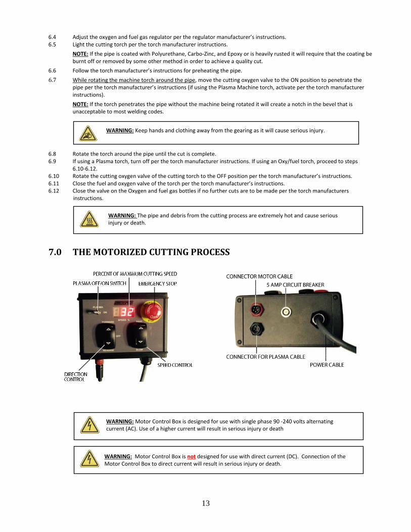
7.0 THE MOTORIZED CUTTING PROCESS
WARNING
WARNING: The pipe and debris from the cutting process are extremely hot and can cause
WARNING: Keep hands and clothing away from the gearing as it will cause serious injury.
Picture 7 – Motor Control Box End View Picture 6 – Motor Control Box Face View
Part Number: 03-0203-008
WARNING: Motor Control Box is designed for use with single phase 90 -240 volts alternating current (AC). Use of a higher current will result in serious injury or death
WARNING: Motor Control Box is not designed for use with direct current (DC). Connection of the Motor Control Box to direct current will result in serious injury or death.
WARNING: The pipe and debris from the cutting process are extremely hot and cause serious injury or death.

14
7.1 Installation of Torch Arm, Torch Carrier Assembly and Oxy/fuel or Plasma Torch per instruction in 5.0 7.2 Depress the Emergency Stop Switch. 7.3 Connect the Motor Cable to surface mount connector of the Motor Control Box. 7.4 Connect the other end of the motor cable to the motor assembly.
NOTE: Verify the cable lock feature is engage at both ends of the motor cable. NOTE: If using a plasma torch system, connect the plasma cable between the Motor Control Box and the plasma torch system in the same manner. Verify the cable lock feature is engaged at both ends. Make sure the Plasma Switch is in the “Off” position.
7.5 Connect the Motor Control Box power cable to the AC electrical receptacle. 7.6 Twist to release the Emergency Stop Switch. 7.7 The digital screen will light with the following. 991 – Indicates that a NEMA 23 motor is in use. 992 – Indicates that a NEMA 34 motor is in use.
993 – Indicates that a heavy-duty NEMA 34 motor is in use. 994 & 995 – Check cable connection at Motor Control Box and Motor. 999 – Indicates the Directional Control Switch is in the “Forward” or “Reverse” position. Move to the “Off” position.
7.8 If no faults are present after the motor number appears, the percent of maximum speed will be displayed in the window.
7.9 Move the Directional Control Switch to the “Forward” or “Reverse” direction. 7.10 Depress the Speed Control Switch until the percent of motor speed reads about 32% or machine speed or control of
the machine can be maintained should an emergency arise. 7.11 Rotate Torch one full turn around the pipe to be sure torch tip will
maintain the same distance around the pipe. NOTE: If the torch tip contacts the pipe or is further away from the pipe at any point during its rotation either the incorrect spacer bolts were selected or the pipe is oversize, undersize or out of round.
7.12 Depress the Emergency Stop Switch. 7.13 Disconnect the Motor Control Box power cable from the AC electrical receptacle.
If using a Plasma Torch, skip to step 7.17. 7.14 Connect the gas hose from the fuel regulator to the left hand thread port 10” long
Oxy/fuel per the manufacturer’s instructions. 7.15 Connect the oxygen hose from the oxygen regulator to the right hand thread port
10” long Oxy/fuel per the manufacturer’s instructions. 7.16 Adjust the oxygen and fuel gas regulator per the regulator manufacturer’s instructions. 7.17 Connect the Motor Control Box power cable to the AC electrical receptacle. 7.18 Twist to release the Emergency Stop Switch. 7.19 Verify the percent of maximum speed is displayed in the window. 7.20 Depress the Speed Control Switch until the percent of motor speed reads about 32% so control of the machine can be
maintained should an emergency arise. 7.21 Move the Directional Control Switch to the “Forward” or “Reverse” direction. If using a Plasma Torch, skip to step 7.24 7.22 Light the cutting torch per the torch manufacturer instructions.
NOTE: If the pipe is coated with Polyurethane, Carbo Zinc, and Epoxy or is heavily rusted it will require that the coating be burnt off or removed by some other method in order to achieve a quality cut.
7.23 Follow the torch manufacturer’s instructions for preheating the pipe.
WARNING: The Oxygen and fuel gas hoses must not be drawn through the molten slag produced by the cutting process
WARNING: The oxygen and fuel hoses must be connected to the right port on the machine torch. Failure to do so may result in serious injury.
WARNING: Goggles, gloves, mask and other appropriate safety attire must be worn during the cutting process.
Picture 8 – Motor Cable
Part Number: 03-0203-200

15
7.24 While the machine is rotating around the pipe, move the cutting oxygen valve to the ON position to penetrate the pipe per the torch manufacturer’s instructions. NOTE: If using a plasma torch in conjunction with the Motor Control Box, depress the Plasma On / Off button on the Motor Control Boxes at this time to turn the plasma torch on. (The plasma cable is designed for use with a Hypertherm, Thermal Dynamics, Victor or new ESAB plasma system.) NOTE: If the torch penetrates the pipe without the machine being rotated it will create a notch in the bevel that is unacceptable to most welding codes.
7.25 Adjust the torch travel speed with Speed Control Switch until a quality cut is achieved. 7.26 Rotate the torch around the pipe until the cut is complete. 7.27 If using an Oxy/fuel torch, rotate the cutting oxygen valve of the cutting torch to the OFF position per the torch
manufacturer’s instructions. If using a Plasma torch, it will be necessary to depress the Plasma On / Off button on the Motor Control Box to turn the torch off.
7.28 Depress the Emergency Stop Switch. 7.29 If using a Plasma torch, skip to step 7.32. 7.30 Close the fuel and oxygen valve of the torch per the torch manufacturer’s instructions. 7.31 Close the Oxygen and fuel valve on the gas bottles per the torch manufacturer’s instructions. 7.32 Disconnect the Motor Control Box power cable from the electrical receptacle. 7.33 Move the Directional Control Switch to the “Off” position.
A NOTE ON BACK BEVELING Remove the torch from the torch carrier assembly. Rotate the Torch Clamp Base and Torch 180 degrees on the Torch Arm and re-tighten with thumbscrew and clamp. Reinstall the torch into the torch carrier assembly. When back beveling, place Torch as close to Saddle as possible without placing flame directly on or near Saddle. The Torch is now positioned for back beveling.
WARNING: When back beveling, the cutting flame and “hot” zone of the pipe is directed toward the operator.
WARNING: The pipe and debris from the cutting process are extremely hot and can cause serious injury.
WARNING: Keep hands and clothing away from the gearing as it will cause serious injury.

16
Figure 4: 3SA Manual Machine Configuration Part #03-0103-000

17
Table 4 – 3SA Manual Machine Parts Identification
ITEM # DESCRIPTION PART # QTY.
1 Saddle 03-0103-001 1
2 Cap Ring 03-0103-003 1
3 Ring Gear 03-0103-002 1
4 Single Bearing Bracket Assembly (Left) 03-0103-004 1
5 Single Bearing Bracket Assembly ( Right) 03-0103-009 1
6 Double Bearing Bracket Assembly 03-0103-011 1
7 Tie Rod Handle 03-0103-019 2
8 Boomer Eye 03-0101-017 2
9 Cap Screw, Hex Head, 5/16” - 18NC x 5/8” 10-56C0-058 2
10 Cap Screw, Hex Head, 5/16” - 18NC x 1” (not shown) 10-56C0-100 4
11 Cap Screw, Hex Head, 5/16”- 18NC x 3/4” (not shown) 10-56C0-034 7
12 Cap Screw, Hex Head, 5/16” - 18NC x 1-1/4” (not Shown) 10-56C0-114 4
13 Nut, Hex 5/16” - 18NC 1H-56C0-000 4
14 Washer, Flat 5/16” 12-0056-F00 9
15 Drive Chain 03-0103-021 2
16 Threaded Stud, 5/16”-18NC (not shown) 01-0194-003 2
17 Wing Nut, 5/16”-18NC (not shown) 1W-56C0-000 2
18 Cap Screw, Hex Head, 5/16”, 18NC x 1-1/2” (not Shown) 10-56C0-112 3

18
Figure 5: Right Single Bearing Bracket Assembly Part Number: 03-0103-009 Left Single Bearing Bracket Assembly Part Number: 03-0103-004
Left Right Table 5 – Right & Left Single Bearing Bracket Assembly Part Identification
ITEM # DESCRIPTION PART # QTY.
1 Left Single Bearing Bracket 03-0103-005 1
2 Right Single Bearing Bracket 03-0103-010 1
3 Sprocket 03-0103-007 1
4 Pinion Gear 03-0102-006 1
5 Axle 03-0103-008 1
6 Bearing 01-0196-012 2
7 Screw, Socket Set, 5/16”- 18NC x 5/16” 19-56C0-056 1
8 Spacer 04-0106-013 1
9 Screw, Socket Set 1/4”- 20NC x 1/4” (not shown) 19-14C0-014 1
10 Spring Pin, 3/16” x 1” 18-3160-100 1
11 Spring Pin, 3/16” x 1-1/2 18-3160-112 1
12 Spiral Ring, 1/2" 01-0179-014 1

19
Figure 6: Double Bearing Bracket Assembly, Part # 03-0103-011 Table 6 – Double Bearing Bracket Assembly Part Identification
ITEM # DESCRIPTION PART# QTY.
1 Double Bearing Bracket 03-0103-017 1
2 Crank handle Assembly 03-0103-012 1
3 Double Sprocket 03-0103-018 1
4 Axle 03-0103-015 1
5 Crank Gear 03-0103-016 1
6 Crank Pinion 03-0103-014 1
7 Bearing 01-0196-012 4
8 Spacer 04-0106-011 2
9 Screw, Socket Set 1/4”- 20NC x 1/4” (not shown) 19-14C0-014 3
10 Pin, Spring 1/8” x 1” 18-1800-100 1
11 Pin, Spring 3/16” x 1-1/2” 18-3160-112 1
12 Flat Head Screw, 5/16-18NC x 1 ¼” 13-56C0-114 2
13 Nut, Hex 5/16-18NC 1H-56C0-000 2
14 Spiral Ring, ½” 01-0179-014 1

20
Figure 7: Motorized 3SA Manual Machine Configuration

21
Table 7 – Motorized 3SA Manual Machine Parts Identification
ITEM # DESCRIPTION PART# QTY. 1 3SA Saddle Machine 03-0103-000 1
Stepper Motor Kit (components included below) 03-0103-SA1 1
2 Motor Coupling 03-0103-032 1
3 NEMA 34 Stepper Motor Assembly 03-0201-058 1
4 Socket Head Cap Screw, #8-32 unc x 1/2" lg. 11-08C0-012 3
5 Socket Head Set Screw, 1/4-20 unc x 1/4" 19-14C0-014 1
6 Button Head Socket Cap Screw, 1/4-20 unc x 1" lg. 26-14C0-100 4
7 Motor Adaptor 03-0103-031 1
8 Motor Control Box complete with motor and plasma cable (See page 13) 03-0203-008 1
9 Cable, Stepper Motor to Stepper Motor Control Box (See page 14) 03-0203-200 1
10 Cable, Plasma Stepper Motor Control Box (Not shown) 03-0203-201 1
11 Connector, NEMA 34 Stepper Motor Assembly (included in item 3) 03-0203-115 1

22
Table 8 – TROUBLESHOOTING – MANUAL MACHINE
MANUAL
Symptom Possible Cause(s) Corrective Action
Machine is cutting out of square
Incorrect Spacers are used Use only Mathey Spacer Bolts.
Customer is cutting tubing. Contact Mathey Dearman Sales Department for Spacers for tubing.
The Spacer Bolts are not in contact with pipe.
Reposition machine so that both Spacer Bolts contact the pipe and re-tighten Boomer.
Torch, Torch Arm or Torch Carrier is loose. Tighten Wing Nuts or Thumbscrews.
Hoses are binding. Wrap the Hose one (1) full turn around the pipe. Rotate the Ring Gear of the machine so the Hoses unwrap during the cutting process.
Machine has been dropped. Send the machine to a Certified Repair Station for resizing Cap Ring, Ring Gear and Saddle.
Torch is at end of Torch Arm. Move the Torch closer to the Ring Gear.
The Pinion Gears are too shallow in the large Ring Gear.
Readjust the Pinion Gear so it is at the proper depth in Ring Gear
Machine hesitates or stops as the Pinion Gear enters
the Ring Gear.
The timing of the Pinion Gears to the Ring Gear is out of adjustment.
Readjust the timing of the Pinion Gear to the Ring Gear per the repair instructions.
The Drive Chain is stretched.
Readjust the both Bearing Brackets to eliminate the slack in the Chain per the repair instructions.
Replace the Drive Chain
MOTORIZED
Machine does not rotate
Bad Motor Control Box to Motor Cable Replace Motor Control Box to Motor Cable
No DC output from motor control box Reset circuit breaker on motor control box
No electrical power at AC wall receptacle Reset circuit breaker at power panel
Emergency stop is depressed Rotate to release Emergency Stop Switch
Directional Control Switch is bad Contact Mathey Dearman
6 pin connector on motor is bad Contact Mathey Dearman
Motor turns and machine does not rotate Setscrew Motor Coupling is loose Retighten Setscrew in Motor Coupling

23
8.0 MAINTENANCE In order to maximize the life of the 3SA Saddle Machine, the maintenance should be performed by an authorized Mathey Dearman Certified Repair Center. The Mathey Dearman Pipe Cutting and Beveling Machines require only minimal maintenance; however, these are precision machines. In order to achieve proper results, make sure your machine is handled with reasonable care and it is kept clean and lubricated. The Saddle Machine should be stored in a protective container such as a Mathey Dearman Machine Storage Box or the original factory shipping crate during transporting or when not in use. The Ring Gear, Pinion Gears, and Drive Chains should be kept clear of slag and other trapped abrasives, especially sand and dirt. The Saddle, Ring Gear, and Cap Ring should be cleaned weekly and the Ring Gear Track Surfaces should be coated with Lubriplate 130-AA or equal lubricant weekly under heavy use and before storing. The Drive Chains and Sprockets should be cleaned regularly and coated with a film of a light oil or lubricant such as WD-40 or equal. The bearings (Figure 5 item 6) in the Single Bearing Brackets (Figure 5) and the bearings (Figure 6 item 7) in the Double Bearing Bracket (Figure 6) are sealed lubricated bearings and should never require replacement. There are 2 thread holes in the side of the Single Bearing Bracket (Figure 5) containing a set screws (Figure 5 item 9) and 2 thread holes in the side of the Double Bearing Bracket (Figure 6) containing a set screws (Figure 6 item 9). These Set Screws should never be loosened or removed except to replace the bearings (Figure 5 item 6) (Figure 6 item 7). Contact Mathey Dearman at 918-447-1288, should any questions arise that are not covered in the manual
8.1 Timing the Ring Gear to the Pinion Gears of the Manual 3SA Adjusting of the timing requires the purchase of 2 Axles (Figure 5 item 5).
Warning: Redrilling of the old Axles will severely weaken the axle causing it to fail
8.1.1 Remove both Tie Rod Handles (Figure 4 item 7) from the Single and Double Bearing Bracket Assemblies (Figure 4 items 4, 5 & 6) by removing Hex Head Cap Screws (Figure 4 item 10 ) and Hex Nuts (Figure 4 item 13) using a 1/2" wrench.
NOTE: Tie Rod Handles (Figure 4 item 7), Hex Head Cap Screws (Figure 4 item 10) and Hex Nuts (Figure 4 item 13) will be used during reassembly
8.1.2 Remove 5/16-18 x 1 1/4” Hex Head Cap Screws (Figure 4 item 12) and 5/16” Washer (Figure 4 item 14) from the Left Single Bearing Bracket (Figure 4 item 4) with a 9/16” wrench.
8.1.3 Remove the Drive Chain (Figure 4 item 15) from the Sprocket of the Left Single Bearing Bracket Assembly (Figure 4 item 4).
8.1.4 Place the Left Single Bearing Bracket Assembly (Figure 4 item 4) in a vise. 8.1.5 With a 5/32” / 4 mm diameter drift punch, remove 3/16” x 1 ½” long Spring Pin (Figure 5 item 11) and 3/16” x 1” long
Spring Pin (Figure 5 item 10) from the single bearing bracket (Figure 5). NOTE: Save 3/16” x 1 ½” long Spring Pin (Figure 5 item 11) and 3/16” x 1” long Spring Pin (Figure 5 item 10) for reuse
at a later time. 8.1.6 With a 5/32” Allen wrench, loosen the Socket Set Screw (Figure 5 item 7) in the Sprocket (Figure 5 item 3) of the
Single Bearing Bracket Assembly (Figure 5). 8.1.7 Press the axle (Figure 5 item 5) out of the Sprocket (Figure 5 item 3) of the Single Bearing Bracket Assembly (Figure 5). 8.1.8 With a 1/4" / 6 mm drift punch, drive the Axle (Figure 5 item 5) out of the Pinion Gear (Figure 5 item 4) of the Single
Bearing Bracket Assembly (Figure 5). 8.1.9 Press the new Axle (Figure 5 item 5) into Pinion Gear (Figure 5 item 4).
Warning: Redrilling of an old Axle will severely weaken the axle
8.1.10 Using the existing hole in the Pinion Gear (Figure 5 item 4) as a guide, drill a 3/16” / 4.7 mm hole completely through the Axle (Figure 5 item 5).
8.1.11 Install the 3/16” x 1” long Spring Pin (Figure 5 item 10) in the 3/16” / 4.7mm hole. 8.1.12 Install the Axle (Figure 5 item 5) / Pinion Gear (Figure 5 item 4) assembly into the Left Single Bearing Bracket Assembly
(Figure 4 item 4). 8.1.13 Place the Sprocket (Figure 5 item 3) on the Axle (Figure 5 item 5) with the hub of the Sprocket facing outward. 8.1.14 Place the Drive Chain (Figure 4 item 15) on the Sprocket of the left Single Bearing Bracket Assembly (Figure 4 item 4)
and the Double Sprocket of the Double Bearing Bracket Assembly (Figure 4 item 6). 8.1.15 When placing the Left Single Bearing Bracket Assembly (Figure 4 item 4) in position, rotate the Pinion Gear (Figure 5
item 4) of the left Single Bearing Bracket Assembly so teeth of the pinion gear mesh in the teeth of Ring Gear (Figure 4 item 3).

24
8.1.16 Install the 5/16-18 x 1 1/4” Hex Head Cap Screws (Figure 4 item 12) and 5/16” Washer (Figure 4 item 14) into the Left Single Bearing Bracket (Figure 4 item 4) and screw into the Saddle (Figure 4 item 1).
8.1.17 There should be a .005” to .007” gap between the Pinion Gear (Figure 5 item 4) and the teeth of Ring Gear (Figure 4 item 3).
8.1.18 Snug the 5/16-8 x 1 1/4” Hex Head Cap Screws (Figure 4 item 12) with a 9/16” wrench. 8.1.19 Tighten the Socket Set Screw (Figure 5 item 7) in the Sprocket (Figure 5 item 3) of the Left Single Bearing Bracket
(Figure 5) with a 5/32” Allen wrench. 8.1.20 Rotate the Ring Gear (Figure 4 item 3) clockwise (as viewed from the front of the machine) check the entry of the
Pinion Gear (Figure 5 item 4) of the Right and Left Single Bearing Bracket Assemblies (Figure 4 items 4 & 5) into the Ring Gear (Figure 4 item 3).
8.1.21 Adjust the Pinion Gear (Figure 5 item 4) of the Single Bearing Brackets (Figure 5) as needed so that it enters the Ring Gear (Figure 4 item 3) without hesitation.
NOTE: When the Pinion Gears (Figure 5 item 4) of the Right and Left Single Bearing Bracket (Figure 4 items 4 & 5) enters the Ring Gear (Figure 4 item 3) it should not suddenly pull the Ring Gear. As the Pinion Gears (Figure 5 item 4) of the Single Bearing Brackets (Figure 4 items 4 & 5) leaves the Ring Gear (Figure 4 item 3) it should not suddenly push the Ring Gear.
8.1.22 Make sure the Pinion Gears (Figure 5 item 4) of the Single Bearing Brackets (Figure 4 items 4 & 5) are evenly spaced in the teeth of the Ring Gear (Figure 4 item 3).
8.1.23 Tighten the Hex Head Cap Screws (Figure 4 item 12) on both sides of the Left Single Bearing Bracket Assembly (Figure 4 item 4) using a 9/16” wrench.
8.1.24 Rotate the Ring Gear (Figure 4 item 3) one (1) full revolution in the clockwise and counterclockwise direction checking the entry of the Ring Gear (Figure 4 item 3) into the Pinion Gears (Figure 5 item 4) of the Right & Left Single Bearing Bracket (Figure 4 items 4 & 5).
NOTE: The entry of the Pinion Gears into the Ring Gear should be smooth and without hesitation. NOTE: When the Pinion Gears (Figure 5 item 4) of the Right and Left Single Bearing Brackets (Figure 4 items 4 & 5)
enters the Ring Gear (Figure 4 item 3) it should not suddenly pull the Ring Gear. As the Pinion Gear (Figure 5 item 4) of the Single Bearing Brackets (Figure 4 items 4 & 5) leave the Ring Gear (Figure 4 item 3) it should not suddenly push the Ring Gear.
8.1.25 Reattach both Tie Rod Handles (Figure 4 item 7) to the Single and Double Bearing Bracket Assemblies (Figure 4 items 4, 5 & 6) with the Hex Head Cap Screws (Figure 4 item 10 ) and Hex Nuts Figure 4 item 13) and tighten with a 1/2" wrench.
8.1.26 Rotate the Ring Gear (Figure 4 item 3) one (1) full revolution in the clockwise and counterclockwise direction rechecking the entry of the Ring Gear into the Pinion (Figure 5 item 4) of the Right & Left Single Bearing Bracket Assembly (Figure 4 items 4 & 5) to assure the entry of the Pinion Gears into the Ring Gear is smooth and without hesitation.
8.1.27 Using the existing hole in the Sprocket (Figure 5 item 3) as a guide, drill through the Axle (Figure 5 item 5) of the Left Single Bearing Bracket (Figure 4 item 4) with a 3/16” drill.
8.1.28 Install 3/16” x 1 ½” long Spring Pin into the Sprocket (Figure 5 item 3). 8.1.29 The machine repair is now complete.
8.2 Installation of New Drive Chains in Manual 3SA Installation of a new Drive Chains (Figure 4 item 15) will also require the purchase of an Axle (Figure 5 item 4).
Warning: Redrilling of the old Axle will severely weaken the axle
8.2.1 Remove both Tie Rod Handles (Figure 4 item 7) from the Single and Double Bearing Bracket Assemblies (Figure 4 items 4, 5 & 6) by removing Hex Head Cap Screws (Figure 4 item 10 ) and Hex Nuts (Figure 4 item 13) using a 1/2" wrench.
NOTE: Save Hex Head Cap Screws (Figure 4 item 10) and Hex Nuts (Figure 4 item 13) 8.2.2 Remove the Hex Head Cap Screws (Figure 4 item 12) and Washer (Figure 4 item 14) from the Left Single Bearing
Bracket Assembly (Figure 4 item 4) with a 9/16” wrench. 8.2.3 Remove the Drive Chain (Figure 4 item 15) from the Sprocket (Figure 5 item 3) of Left Single Bearing Bracket Assembly
(Figure 4 item 4) and the Double Sprocket (Figure 6 item 3) of the Double Bearing Bracket Assembly (Figure 4 item 6) 8.2.4 Place the Left Single Bearing Bracket Assembly (Figure 4 item 4) on the table

25
8.2.5 Remove the outermost Hex Head Cap Screw (Figure 4 item 12) and Washer (Figure 4 item 14) from the Right Single Bearing Bracket Assembly (Figure 4 item 5) with a 9/16” wrench. Loosen the centermost cap screw (Figure 4 item 12).
8.2.6 Tilt the Right Single Bearing Bracket Assemblies inward toward the Double Bearing Bracket Assembly (Figure 4 item 6) 8.2.7 Remove the Drive Chain (Figure 4 item 15) from the Sprocket (Figure 5 item 3) of the Right Single Bearing Bracket
Assemblies (Figure 4 item 5) and the Double Sprocket (Figure 6 item 3) of the Double Bearing Bracket Assembly (Figure 4 item 6).
8.2.8 Install the new Drive Chain (Figure 4 item 15) onto the Sprocket (Figure 5 item 3) of the Right Single Bearing Bracket Assemblies (Figure 4 item 5) and the Double Sprocket (Figure 6 item 3) of the Double Bearing Bracket Assembly (Figure 4 item 6).
8.2.9 Move the Single Bearing Bracket (Figure 4 item 5) into position on the backside of Saddle (Figure 4 item 1), while moving Ring Gear (Figure 4 item 3) as needed so the teeth of the Pinion Gear (Figure 5 item 4) of the Right Single Bearing Bracket Assembly (Figure 4 item 5) mesh with the teeth of the Ring Gear (Figure 4 item 3)
8.2.10 Reinstall the outermost Hex Head Cap Screw (Figure 4 item 12) and Washer (Figure 4 item 14) into the Right Single Bearing Bracket Assembly (Figure 4 item 5) and thread into Saddle (Figure 4 item 1)
8.2.11 Adjust the Pinion Gear (Figure 5 item 4) of the Right Single Bearing Bracket Assembly (Figure 4 item 5) so there is .005” to .007” gap between the Pinion Gear (Figure 5 item 4) and the teeth of Ring Gear (Figure 4 item 3).
8.2.12 Tighten all Hex Head Cap Screws (Figure 4 item 12) that hold the Right Single Bearing Bracket Assembly (Figure 4 item 5) in position on the Saddle (Figure 4 item 1) with a 9/16” wrench.
8.2.13 Place the Left Single Bearing Bracket Assembly (Figure 4 item 4) in a vise. 8.2.14 With a 5/32” / 4 mm diameter drift punch, remove 3/16” x 1 ½” long Spring Pin (Figure 5 item 11) and 3/16” x 1” long
Spring Pin (Figure 5 item 10). NOTE: Save 3/16” x 1 ½” long Spring Pin (Figure 5 item 11) and 3/16” x 1” long Spring Pin (Figure 5 item 10) for reuse
at a later time. 8.2.15 With a 5/32” Allen wrench, loosen the Socket Set Screw (Figure 5 item 7) in the Sprocket (Figure 5 item 3) of the
Single Bearing Bracket Assembly (Figure 5). 8.2.16 Remove Sprocket (Figure 5 item 3) from the Axle (Figure 5 item 5) of the Single Bearing Bracket Assembly (Figure 5). 8.2.17 With a 1/4" / 6 mm drift punch, drive the Axle (Figure 5 item 5) / Pinion Gear (Figure 5 item 4) assembly out of the
Left Single Bearing Bracket Assembly (Figure 4 item 4). 8.2.18 With a 1/4" / 6 mm drift punch, drive Axle (Figure 5 item 5) out of Pinion Gear (Figure 5 item 4). 8.2.19 Press the new Axle (Figure 5 item 5) into Pinion Gear (Figure 5 item 4).
Warning: Redrilling of the old Axle will severely weaken the axle
8.2.20 Using the existing hole in the Pinion Gear (Figure 5 item 4) as a guide, drill a 3/16” / 4.7 mm hole completely through the Axle (Figure 5 item 5).
8.2.21 Install the 3/16” x 1” long Spring Pin (Figure 5 item 10) in the 3/16” / 4.7 mm hole. 8.2.22 Install the Axle (Figure 5 item 5) / Pinion Gear (Figure 5 item 4) assembly into the Left Single Bearing Bracket Assembly
(Figure 4 item 4). 8.2.23 Place the Sprocket (Figure 5 item 3) on the Axle (Figure 5 item 5) with the hub of the Sprocket facing outward. 8.2.24 Place the new Drive Chain (Figure 4 item 15) on the Sprocket (Figure 5 item 3) and the Double Sprocket (Figure 6 item
3) of the Double Bearing Bracket Assembly (Figure 4 item 6). 8.2.25 When placing the Left Single Bearing Bracket Assembly (Figure 4 item 4) in position, rotate the Pinion Gear (Figure 5
item 4) so the teeth mesh in the teeth of Ring Gear (Figure 4 item 3). 8.2.26 Install the Hex Head Cap Screws (Figure 4 item 12) and Washer (Figure 4 item 14) into the Left Single Bearing Bracket
(Figure 4 item 4) and screw into the Saddle (Figure 4 item 1). 8.2.27 There should be a .005” to .007” gap between the Pinion Gear (Figure 5 item 4) and the teeth of Ring Gear (Figure 4
item 3). Make sure the Pinion Gears (Figure 5 item 4) of the Single Bearing Brackets (Figure 4 items 4 and 5) are evenly spaced in the teeth of the Ring Gear (Figure 4 item 3).
8.2.28 Snug the Hex Head Cap Screws (Figure 4 item 12) with a 9/16” wrench. 8.2.29 Tighten the Socket Set Screw (Figure 5 item 7) in the Sprocket (Figure 5 item 3) of the Left Single Bearing Bracket
(Figure 4 item 4) with a 5/32” Allen wrench. 8.2.30 Rotate the Ring Gear (Figure 4 item 3) clockwise (as viewed from the front of the machine) check the entry of the
Pinion Gear (Figure 5 item 4) of the Right and Left Single Bearing Bracket Assemblies (Figure 4 items 4 & 5) into the Ring Gear (Figure 4 item 3).

26
8.2.31 Adjust the Pinion Gear (Figure 5 item 4) of the Single Bearing Brackets (Figure 5) as needed so that it enters the Ring Gear (Figure 4 item 3) without hesitation.
NOTE: When the Pinion Gears (Figure 5 item 4) of the Right and Left Single Bearing Bracket (Figure 4 items 4 and 5) enters the Ring Gear (Figure 4 item 3) it should not suddenly pull the Ring Gear. As the Pinion Gear (Figure 5 item 4) of the Single Bearing Bracket (Figure 4 items 4 and 5) leaves the Ring Gear (Figure 4 item 3) it should not suddenly push the Ring Gear.
8.2.32 Tighten the Hex Head Cap Screws (Figure 4 item 12) on both sides of the Left Single Bearing Bracket Assembly (Figure 4 item 4) using a 9/16” wrench.
8.2.33 Rotate the Ring Gear (Figure 4 item 3) one (1) full revolution in the clockwise and counterclockwise direction checking the entry of the Ring Gear (Figure 4 item 3) into the Pinion Gears (Figure 5 item 4) of the Right & Left Single Bearing Bracket (Figure 4 items 4 and 5).
NOTE: The entry of the Pinion Gears into the Ring Gear should be smooth and without hesitation. NOTE: When the Pinion Gears (Figure 5 item 4) of the Right and Left Single Bearing Bracket (Figure 4 items 4 and 5)
enters the Ring Gear (Figure 4 item 3) it should not suddenly pull the Ring Gear. As the Pinion Gear (Figure 5 item 4) of the Single Bearing Brackets (Figure 4 items 4 and 5) leaves the Ring Gear (Figure 4 item 3) it should not suddenly push the Ring Gear.
8.2.34 Reattach both Tie Rod Handles (Figure 4 item 7) to the Single and Double Bearing Bracket Assemblies (Figure 4 items 4, 5 & 6) with the Hex Head Cap Screws (Figure 4 item 10) and Hex Nuts (Figure 5 item 13) and tighten with a 1/2" wrench.
8.2.35 Rotate the Ring Gear (Figure 4 item 3) one (1) full revolution in the clockwise and counterclockwise direction; double checking the entry of the Ring Gear into the Pinion (Figure 5 item 4) of the Right & Left Single Bearing Bracket Assembly (Figure 4 items 4 and 5) to insure the entry of the Pinion Gears into the Ring Gear is smooth and without hesitation.
8.2.36 Using the existing hole in the Sprocket (Figure 5 item 3) as a guide, drill through the Axle (Figure 5 item 5) of the Left Single Bearing Bracket (Figure 4 item 4) with a 3/16” drill.
8.2.37 Install 3/16” x 1 ½” long Spring Pin into the Sprocket (Figure 5 item 11). 8.2.38 The machine is now ready for the cutting operation.
8.3 Retiming of the Machine with Stepper Motor 8.3.1 Remove #8-32 x ½” lg. Socket Head Cap Screws (Figure 7 item 4) that attach the Motor Adaptor (Figure 7 item 7) to
the Double Bearing Bracket Assembly (Figure 4 item 6) of the 3SA Saddle Machine. 8.3.2 Grasp the Motor Adaptor (Figure 7 item 7) and remove the Motorizing kit from the Double Bearing Bracket Assembly
(Figure 4 item 6) 8.3.3 Loosen the ¼-20 Socket Head Set Screw (Figure 7 item 5) located in the Motor Coupling (Figure 7 item 2). 8.3.4 Remove the Motor Coupling. 8.3.5 Install the Crank Handle Assembly (Figure 6 Item 2). 8.3.6 Follow instruction in section 8.1 on page 23. 8.3.7 Reverse steps 8.3.1 thru 8.3.5. 8.3.8 Place the machine on a pipe. 8.3.9 Connect the Motor Cable to the Motor Assembly (Figure 8 item 3) and to the Motor Control Box. 8.3.10 Depress the Emergency Stop Switch. 8.3.11 Move the Directional Control Switch to the “Off” position. 8.3.12 Plug the Motor Control Box into a wall outlet having an output of 90 to 240 volts AC. 8.3.13 Twist to release the Emergency Stop Switch. 8.3.14 The Digital Screen will light up showing the following.
991 – Indicates the stepper motor is NEMA 23 992 – Indicates the Stepper Motor is NEMA 34 993 – Indicates the Stepper Motor is a heavy-duty NEMA 994 & 995 – Check cable connection at motor and motor control box. 999 – Indicates the Directional Control Switch is in the “Forward” or “Reverse” position. Move to the “Off” position. NOTE: If any other codes appear, contact Mathey Dearman prior to continuing the cutting process.
8.3.15 If no faults are present after the motor number appears, the percent of maximum speed will be displayed in the window.
8.3.16 Move the Directional Control Switch to the “Forward” or “Reverse” direction. 8.3.17 Depress the Speed Control Switch until the percent of motor speed reads about 32% so control of the machine can be
maintained should an emergency arise. 8.3.18 If the motorized unit is operating improperly see the trouble shooting in Table 8.

27
8.4 Replacement of Drive Chain of the Machine with Stepper Motor 8.4.1 Remove #8-32 x ½” lg. Socket Head Cap Screws (Figure 7 item 4) that attach the Motor Adaptor (Figure 7 item 7) to
the Double Bearing Bracket Assembly (Figure 4 item 6) of the 3SA Saddle Machine. 8.4.2 Grasp the Motor Adaptor (Figure 7 item 7) and remove the Motorizing kit from the Double Bearing Bracket Assembly
(Figure 4 item 6) 8.4.3 Loosen the ¼-20 Socket Head Set Screw (Figure 7 item 5) located in the Motor Coupling (Figure 7 item 2). 8.4.4 Remove the Motor Coupling. 8.4.5 Install the Crank Handle Assembly (Figure 6 Item 2). 8.4.6 Follow instruction in section 8.2 on page 24. 8.4.7 Reverse steps 8.4.1 thru 8.4.5. 8.4.8 Place the machine on a pipe. 8.4.9 Connect the Motor Cable to the Motor Assembly (Figure 8 item 3) and to the Motor Control Box. 8.4.10 Depress the Emergency Stop Switch. 8.4.11 Move the Directional Control Switch to the “Off” position. 8.4.12 Plug the Motor Control Box into a wall outlet having an output of 90 to 240 volts AC. 8.4.13 Twist to release the Emergency Stop Switch. 8.4.14 The Digital Screen will light up showing the following.
991 – Indicates the stepper motor is NEMA 23 992 – Indicates the Stepper Motor is NEMA 34 993 – Indicates the Stepper Motor is a heavy-duty NEMA 994 & 995 – Check cable connection at motor and motor control box. 999 – Indicates the Directional Control Switch is in the “Forward” or “Reverse” position. Move to the “Off” position. NOTE: If any other codes appear, contact Mathey Dearman prior to continuing the cutting process.
8.4.15 If no faults are present after the motor number appears, the percent of maximum speed will be displayed in the window.
8.4.16 Move the Directional Control Switch to the “Forward” or “Reverse” direction. 8.4.17 Depress the Speed Control Switch until the percent of motor speed reads about 32% so control of the machine can be
maintained should an emergency arise. 8.4.18 If the motorized unit is operating improperly see the trouble shooting in Table 8. 8.5 Installation of the Stepper Motor Kit 8.5.1 Loosen the set screw (Figure 6 item 9) in the Crank Handle Assembly (Figure 6 item 2). 8.5.2 Remove the Crank Handle Assembly (Figure 6 item 2) from the shaft of the Crank Pinion (Figure 6 item 6). 8.5.3 Make sure the 3 threaded holes in the face of Double Bearing Bracket (Figure 6 item 1) are not damaged and free of
debris. 8.5.4 Install the Motor Coupling (Figure 7 item 2) on to the shaft of the Crank Pinion (Figure 6 item 6). 8.5.5 Tighten the ¼-20 Set screw (Figure 7 item 5) located in the Motor Coupling (Figure 7 item 2). 8.5.6 Slide the Motor Adaptor (Figure 7 item 7) over the Motor Coupling (Figure 7 item 2) and align the holes in the Motor
Adaptor with the threaded holes in the face of the Double Bearing Bracket (Figure 6 item 1). 8.5.7 Place the #8-32 Socket Head Screws (Figure 7 item 4) into the holes of the Motor Adaptor (Figure 7 item 7) and thread
them into the Double Bearing Bracket (Figure 6 item 1). 8.5.8 Align the flat in the hole of the Motor Coupling (Figure 7 item 2) with the flat on the shaft of the Motor Assembly
(Figure 7 item 3) and insert the motor shaft in the Motor Coupling until the face of the Motor Assembly is flush with the face of the Motor Adaptor (Figure 7 item 7).
8.5.9 Install the 1/4-20 x 1” long Button Head Socket Cap Screws (Figure 7 item 6) through the flange holes in the Motor Assembly (Figure 7 item 3) and thread them into the thread holes of the Motor Adaptor (Figure 7 item 7).
8.5.10 Place the machine on a pipe. 8.5.11 Connect the Motor Cable to the Motor Assembly (Figure 8 item 3) and to the Motor Control Box. 8.5.12 Depress the Emergency Stop Switch. 8.5.13 Move the Directional Control Switch to the “Off” position. 8.5.14 Plug the Motor Control Box into a wall outlet having an output of 90 to 240 volts. 8.5.15 Twist to release the Emergency Stop Switch. 8.5.16 The Digital Screen will light up showing the following.
991 – Indicates the stepper motor is NEMA 23. 992 – Indicates the Stepper Motor is NEMA 34. 993 – Indicates the Stepper Motor is a heavy-duty NEMA. 994 & 995 – Check cable connection at motor and motor control box. 999 – Indicates the Directional Control Switch is in the “Forward” or “Reverse” position. Move to the “Off” position.

28
NOTE: If any other codes appear contact Mathey Dearman prior to continuing the cutting process. 8.5.17 If no faults are present after the motor number appears, the percent of maximum speed will be displayed in the
window. 8.5.18 Move the Directional Control Switch to the “Forward” or “Reverse” direction. 8.5.19 Depress the Speed Control Switch until the percent of motor speed reads about 32% so control of the machine can be
maintained should an emergency arise. 8.5.20 If the motorized unit is operating improperly see the trouble shooting in Table 8. 8.6 Disassembly and Repair of the Single and Double Bearing Bracket Assemblies. Contact Mathey Dearman for instructions, if disassembly and repair of the Single and Double Bearing Bracket
Assemblies is required
8.7 Storage If the machine will not be used for a period of the time, the machine should be cleaned and regreased with Lubriplate 130-AA. The machine should be stored in a clean and dry place protected from damage.
9.0 LIMITATIONS Mathey Dearman is not and will not be responsible for
• Improper use of the Saddle Machine. • Use of the Saddle Machine in violation of any national and/or international electrical and safety regulations in
force. • Connection of the Motorized Saddle Machine to an improper or wrong power source. • Faulty maintenance. • Unauthorized modification and/or service of the Saddle Machine. • Use of non-original spare parts or non-specific components. • Lack of observance or partial observance of the operating and maintenance instructions. • Unusual events such as natural disasters, wars, strikes or similar events.
10.0 MACHINE SAFETY Users should follow these standard safety procedures in order to observe and prevent the safety of all employees using the machine: • Operators must use the wear safety goggles and shoes and should be suitably dressed for the working
environment. • Operators and maintenance personnel should read and understand the Parts and Operating Manual prior to
attempting any type of function. • Check the electrical connections prior to operating the Motorized Saddle Machine. • Turn off the electrical power source prior to disconnecting the electrical connector from the power source. • Observe all health warnings listed in the Parts and Operating Manual.
11.0 CONDITION OF USE 11.1 Condition of use
• The purpose of the Saddle Machine is indicated on section 2.1. Any other use, different from what is listed in section 2.1, could be hazardous to the operator.
• The Saddle Machine should be placed in a safe place protected from rain, extreme humidity, mud or accidental impact.
• The Motorized Saddle Machine should never be operated in an extremely humid environment such as fog or rain. • Adopt all the safety devices supplied or suggested by the manufacturer. • No modification to the Saddle Machine or its accessories should be done without the previous written approval by
the manufacturer. • Remember the Motor Control Box is attached to the power source current is applied to the motor control box. The
Motor Control Box should be disconnected from the power source when not in use.

29
11.2 Use of the Saddle Machine not allowed by the Manufacturer • Tampering with the electrical circuit of the Motorized Saddle Machine. • Operation of the Saddle without the appropriate safety devices. • Perform maintenance with electrical current applied to the Saddle Machine. • Use of a liquid or foam fire extinguisher to extinguish a fire in or near the Saddle Machine.
12.0 DISPOSAL OF THE SADDLE MACHINE 12.1 General Information
Do not dispose of any components recklessly without regard for the environment. Separate the components by category for a possible reuse. All national and state regulations should be followed when disposing of waste.
12.2 Composition of the Major Components Component Description Material Saddle, Cap Ring, Ring Gear, Single & Double Bearing Bracket Aluminum Step Spacers, Motor Adaptor, Motor Coupling, Motor Control Box Case
Pinion Gear, Boomer, Boomer Chain, Spring, Spring Snap, Axle Steel Drive Chain, Crank Gear and Sprocket, Spacer Bolts, Bearings,
Electrical Cords Rubber coated copper Cord Retention Holder Plastic
13.0 WARRANTY For warranty information see www.mathey.com
Table 9 – Commercial Pipe Sizes and Wall Thickness
Pipe Size
OD (inches)
Nominal Wall Thickness for Schedule
10 20 40 Extra Strong 80 120 140 160 XX
Strong 12 12 ¾ .180 .250 .406 .500 .688 1.000 1.125 1.312 -- 14 14 .250 .312 .437 .500 .750 1.093 1.250 1.406 -- 16 16 .250 .312 .500 .500 .843 1.218 1.437 1.593 -- 18 18 .250 .312 .562 .500 .937 1.375 1.562 1.781 -- 20 20 .250 .375 .593 .500 1.031 1.500 1.750 1.968 --