3M Technical Information Installation- and User...
89
3M Technical Information Installation- and User Manual 3M™ Driver Feedback Sign DFS 700
-
Upload
hoangxuyen -
Category
Documents
-
view
218 -
download
2
Transcript of 3M Technical Information Installation- and User...
3M Technical Information
Installation- and User Manual 3M™ Driver Feedback Sign DFS 700
Technical Information DFS 700 / 04.2009 II
Manufacturer and Distributor
3M Deutschland GmbH
Traffic Safety Systems Division
Carl-Schurz-Strasse 1
P.O. Box 10 04 22
D-41453 Neuss
Phone: +49(0)2131 / 14-7331
Fax: +49(0)2131 / 14-3694
Email: [email protected]
Internet: www.3M.com/de
For questions please first contact your local dealer that you obtained your DFS 700 from.
All rights reserved
© 3M Deutschland GmbH, Neuss, 2008
Technical Information DFS 700 / 04.2009 III
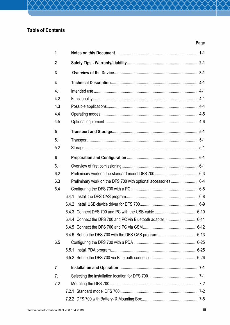
Table of Contents
Page
1 Notes on this Document.............................................................................. 1-1
2 Safety Tips - Warranty/Liability................................................................... 2-1
3 Overview of the Device............................................................................... 3-1
4 Technical Description.................................................................................. 4-1
4.1 Intended use .................................................................................................. 4-1
4.2 Functionality................................................................................................... 4-1
4.3 Possible applications...................................................................................... 4-4
4.4 Operating modes............................................................................................ 4-5
4.5 Optional equipment ........................................................................................ 4-6
5 Transport and Storage................................................................................. 5-1
5.1 Transport........................................................................................................ 5-1
5.2 Storage .......................................................................................................... 5-1
6 Preparation and Configuration ................................................................... 6-1
6.1 Overview of first comissioning........................................................................ 6-1
6.2 Preliminary work on the standard model DFS 700 ......................................... 6-3
6.3 Preliminary work on the DFS 700 with optional accessories.......................... 6-4
6.4 Configuring the DFS 700 with a PC ............................................................... 6-8
6.4.1 Install the DFS-CAS program.................................................................... 6-8
6.4.2 Install USB-device driver for DFS 700....................................................... 6-9
6.4.3 Connect DFS 700 and PC with the USB-cable ....................................... 6-10
6.4.4 Connect the DFS 700 and PC via Bluetooth adapter.............................. 6-11
6.4.5 Connect the DFS 700 and PC via GSM.................................................. 6-12
6.4.6 Set up the DFS 700 with the DFS-CAS program .................................... 6-13
6.5 Configuring the DFS 700 with a PDA........................................................... 6-25
6.5.1 Install PDA program................................................................................ 6-25
6.5.2 Set up the DFS 700 via Bluetooth connection......................................... 6-26
7 Installation and Operation........................................................................... 7-1
7.1 Selecting the installation location for DFS 700............................................... 7-1
7.2 Mounting the DFS 700 ................................................................................... 7-2
7.2.1 Standard model DFS 700.......................................................................... 7-2
7.2.2 DFS 700 with Battery- & Mounting Box..................................................... 7-5
Technical Information DFS 700 / 04.2009 IV
7.3 Connecting and switching electrical power .................................................... 7-7
7.3.1 Mains operation with the standard model.................................................. 7-8
7.3.2 Mains operation using Battery- & Mounting Box ....................................... 7-9
7.3.3 Buffered mains operation with Battery and Charger ................................. 7-9
7.3.4 Battery operation with one or two Batteries............................................. 7-11
7.3.5 Power supply to the GSM/GPRS Modem ............................................... 7-12
8 Analysis of Speed Data Measurements ..................................................... 8-1
8.1 Transfering measurements to PC or PDA...................................................... 8-1
8.2 Assigning measurements to a location........................................................... 8-2
8.3 Viewing measurements.................................................................................. 8-3
8.4 Creating reports ............................................................................................. 8-4
9 Service and Maintenance ............................................................................ 9-1
9.1 Cleaning......................................................................................................... 9-1
9.2 Maintenance .................................................................................................. 9-1
9.3 Symptom / solution table................................................................................ 9-2
9.4 Diagnostic status check ................................................................................. 9-8
9.5 Firmware update ............................................................................................ 9-9
10 Technical Data............................................................................................ 10-1
Technical Information DFS 700 / 04.2009 1-1
1 Notes on this Document
These operating instructions for the DFS 700 Speed Feedback and Warning System are a
basis for the faultless operation of the 3MTM Driver Feedback Sign DFS 700 by the operator.
In the operating instructions the equipment is given the abbreviated name DFS 700.
The responsible installers and operators must read, understand and follow these operating
instructions. Only with knowledge of these operating instructions can errors damage and injury
be avoided and fault-free operation assured.
The operating instructions are to be kept within easy reach of the DFS 700 and accessible to
the operators and maintenance personnel.
3M accepts no warranty and no liability for operating faults or damage that arises as a result of
failure to follow these operating instructions.
Particular subjects are highlighted as follows:
Working and operating procedures, which have to be followed exactly so as to exclude
life-threatening injuries.
Working and operating procedures, which have to be followed exactly so as to exclude
danger to persons.
Working and operating procedures, which have to be followed exactly so as to damage
to or destruction of the equipment.
Technical information to which the equipment operator must pay particular attention.
The picture presentations are numbered sequentially per chapter. Some of the figures have
legends. References to figures in the text, e.g. (7.1 Item 2), mean:
7.1 = Figure 7.1
Item 2 = Item 2 of the legend to the picture.
In the event of technical problems not addressed in these instructions, please contact
your dealer or local 3M subsidiary.
NOTE

Technical Information DFS 700 / 04.2009 1-2
Technical Information DFS 700 / 04.2009 2-1
2 Safety Tips - Warranty/Liability
Basic Information
(1) The DFS 700 has been built in accordance with state-of-the-art technology and
recognised safety rules and norms in the EC Guideline. Nevertheless, dangers to the life
and limb of the user or a third party, or impairments to the device or other property may
occur with its use.
(2) Only use the DFS 700 in a technically perfect condition and in accordance with legal
provisions, in full awareness of safety and dangers by following the operating
instructions! In particular, repair faults that may impair safety immediately yourself or
have them repaired by the service company.
(3) The DFS 700 is exclusively intended to measure, display and record the speed,
measured by the built-in radar equipment, of vehicles passing in front of it. An alternative
or more extensive use is deemed to be improper.
The manufacturer/supplier is not liable for damages occurring as a result
of this. The user alone bears the risk.
Proper use also includes following the operating instructions and
complying with the service and maintenance conditions.
(4) Keep the operating instructions within reach in the place where the device is installed.
(5) In addition to the operating instructions, all generally valid legal and other binding
regulations governing accident prevention and protection of the environment are to be
obeyed and applied!
(6) The DFS 700 is to be set up in traffic in accordance with EN 12899-1 “Fixed vertical road
traffic signs - Part 1 Fixed Signs”. The equipment must only be mounted on a fixed pole
or a solid fixture.
(7) Select the setup site such that the work of setting up is not endangered by traffic. If
necessary secure the setup site with reflective tapes or warning signs and, where
appropriate, work with auxiliary personnel. Only work with approved lifting gear. Where
ladders are used, support them.
Technical Information DFS 700 / 04.2009 2-2
(8) The equipment must not extend into the free space of the traffic to be monitored, so it
can not impair traffic.
(9) The personnel charged with working on the equipment must read these operating
instructions and this chapter “Safety Tips” in particular before work begins. This applies
most particularly to personnel employed only occasionally, e.g. for connecting the
equipment to mains power.
(10) Follow the safety advices on the device and keep them in a legible condition.
(11) Where safety-relevant changes occur to the equipment, shut it down immediately. Have
the fault repaired.
(12) Do not make changes, additions and conversions to the equipment unless they are
expressly provided for in these operating instructions (e.g. replacing the frame,
connecting external flashing lights, etc.). This also applies to the fitting and adjustment of
safety devices.
(13) Spare parts must meet the technical requirements specified by the manufacturer. Only
original 3M spare parts guarantee this.
(14) Only employ trained, properly instructed and authorised personnel. Clearly specify the
responsibility of the personnel for operation and assessment.
Safety Tips for Operation
(15) Refrain from any method of working that puts safety at risk.
(16) In the event of functional faults shut the equipment down and secure it. Have faults
repaired immediately.
(17) Switch the equipment on and off, and monitor control displays as specified in the
operating instructions.
(18) Lay the mains cable such that it is not under tension or causes obstruction. Nothing
should be placed on the cable.
(19) Where an earth cable is used, the earth conductor must have a suitable cross-section
and connect into a grounding system of safe capacity.
(20) For CE compliance please keep attached cables below 3 m length.
Technical Information DFS 700 / 04.2009 2-3
Notes on certain types of danger
Electrical power
(1) To connect the DFS 700 to the public power supply outdoors, a connection must be
available that satisfies the local electrical guidelines and safety requirements.
The power supply line phase [brown/black wire] must be secured with a suitable
fuse, typically 4 to 6 A. Otherwise the electronics in the DFS 700 may be damaged
or destroyed in case of over-current.
When the DFS 700 is in a fixed installation, e.g. to street lights, a disconnectable
over-current protective device (max. 6A) according to EN60950 must be installed
between the power supply line and the DFS 700. For service work on the DFS 700
the power supply must be disconnected via the over-current protective device.
The over-current protective device is to be installed in accordance with the local
electrical guidelines and safety requirements. Therefore in Scandinavia, for
example, a cut out must have a 2-pole connection against grounding.
(2) The electrical connections must always be produced in accordance with the
requirements for the intended location. In the case of fixed installations the plug on the
power supply unit or the Charger may have to be removed. If the plug is still to be used,
then an adequately waterproof, weather-resistant, and properly mounted socket with
protection to the power line as specified above is to be provided.
(3) Only use fuses of the prescribed rating. In the event of faults in the power supply shut
the equipment down immediately.
(4) Work on the electrical equipment or fittings (e. g. Charger) must only be carried out by a
qualified electrician or by trained personnel under the management and supervision of a
qualified electrician in accordance with electrical engineering rules.
(5) Parts, on which tests, maintenance and repair are being carried out, must have the
power to them disconnected. The disconnected parts must be initially tested for zero
voltage then grounded and shorted. Adjacent parts with power still connected to them
must be isolated!
(6) The electrical equipment on the DFS 700 is to be checked regularly. Defects, such as
loose connections or burnt cables, must be removed immediately.
NOTE
Technical Information DFS 700 / 04.2009 2-4
(7) If work is required on disconnected parts, take a second person along who can trigger a
power-down in an emergency.
(8) Use only insulated tools!
Power Supply Unit Box (if available)
(1) As a basic principle the Power Supply Unit box is provided for use on the DFS 700 (on
the frame or in the Battery- & Mounting Box), but can also be used separately
considering the vertical alignment when placed indoors (workshop, office) or outdoors
(next to mounting location).
(2) Do not open/disassemble the Power Supply Unit box. Completely replace damaged or
non-functioning Power Supply Unit boxes, including the two cables. This also applies to
cable damage.
Battery (if available)
(1) Do not remove the Battery pole caps. A short circuit, which can destroy the Battery, is
created by bridging the positive and negative poles with metal. There is a risk of injury as
a result of parts heating up or arcing voltages.
(2) The Battery cable and poles should be undamaged; otherwise the Battery is to be
replaced.
(3) As a basic principle charge the Battery used in the Battery- & Mounting Box using the
Charger.
(4) Only charge and discharge removed Batteries in ventilated areas, as charging causes
poisonous and flammable gases to develop. No Smoking! Keep children away!
(5) Do not cover the Battery and do not place on radiators, heaters or open fires. Avoid
contact with water.
The optional Battery- & Mounting Box is the best location for the Battery while
charging and in use. NOTE
Technical Information DFS 700 / 04.2009 2-5
(2) The Battery fluid is corrosive! On contact with skin, the eyes or clothing, wash the area
affected in plenty of water. On physical contact consult a doctor (contact with sulphuric
acid).
(3) The Battery must be recycled or properly disposed of. Disposing of the Battery in
domestic waste is prohibited.
(4) The Battery may not be beaten, disassembled, damaged, dumped or burned in an open
fire. The danger of an explosion otherwise exists.
(5) Only transport Batteries wearing eye protection and acid-resistant gloves.
(6) Only work on Batteries wearing eye protection and protective clothing.
Battery Charger (if available)
(1) The Battery Charger is exclusively approved for charging the DFS 700 Battery.
(2) As a basic principle the Charger is provided for indoor use (workshop, office) but inside
the Battery- & Mounting Box it can also be used outdoors. To avoid overheating, do not
cover the Charger during a charging cycle.
(3) The epoxy resin-filled Charger is spray-proof, but must not be immersed in water for long
periods (IP67).
(4) The mains socket or a power disconnect must be easily accessible. If an operating fault
occurs, remove the plug from the socket immediately or disconnect the power.
(5) Hazardous voltages exist inside the Charger. Do not open/dismantle the Charger. Avoid
damage.
(6) The charging cycle can cause explosive gases to develop. Avoid sparks and open
flames. Ensure there is adequate ventilation during a charging cycle. The Charger may
not be used in the immediate vicinity of combustible anaesthetic gases. The plastic
casing should not come into contact with oil or grease etc., as it can be dissolved by
chemicals and solvents.
The optional Battery- & Mounting Box is the best location for the Charger while
charging and in use.
NOTE
Technical Information DFS 700 / 04.2009 2-6
Radar
(1) The radar beam may be damaging to the eyes. Do not look directly into radar radiation!
Return and Waste-Disposal of Electrical and Electronic Devices and Batteries
(1) Please contact your 3M dealer or 3M Customer Service about the free return of electrical
and electronic devices and their components in accordance with WEEE Guideline
2002/96 EC.
(2) Old Batteries are to be returned to the distributor or to a public waste-disposal facility.
Warranty
All warranty and liability matters regarding the DFS 700 are defined by the current
sales contractual conditions, provided that legal regulations don't state otherwise.
Damages caused by improper installation or operation or as a result of excessive
operational demands or the use of unsuitable product components is excluded from
any kind of warranty and liability in all cases.
The equipment must only be used by properly trained persons. Otherwise the
warranty according to the delivery terms and conditions expires immediately.
Device Identification
The type label bearing the CE mark is located on the rear of the speed display device.
The type label gives the following information:
• Manufacturer’s details
• Device type
• Serial number
• Electrical data.
NOTE
Technical Information DFS 700 / 04.2009 3-1
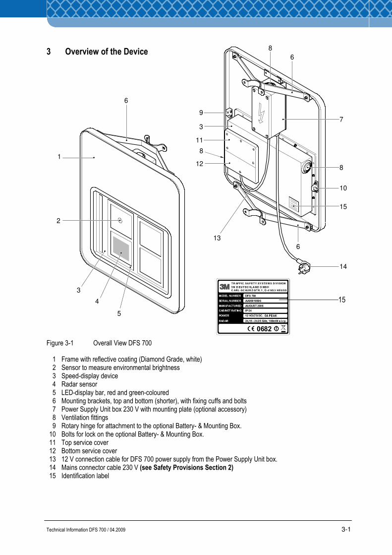
3 Overview of the Device
Figure 3-1 Overall View DFS 700
1 Frame with reflective coating (Diamond Grade, white) 2 Sensor to measure environmental brightness 3 Speed-display device 4 Radar sensor 5 LED-display bar, red and green-coloured 6 Mounting brackets, top and bottom (shorter), with fixing cuffs and bolts 7 Power Supply Unit box 230 V with mounting plate (optional accessory) 8 Ventilation fittings 9 Rotary hinge for attachment to the optional Battery- & Mounting Box. 10 Bolts for lock on the optional Battery- & Mounting Box. 11 Top service cover 12 Bottom service cover 13 12 V connection cable for DFS 700 power supply from the Power Supply Unit box. 14 Mains connector cable 230 V (see Safety Provisions Section 2) 15 Identification label
1
2
3
4
5
6
7
8
8
8
6
6
9
3
10
11
12
13
14
15
15
Technical Information DFS 700 / 04.2009 3-2
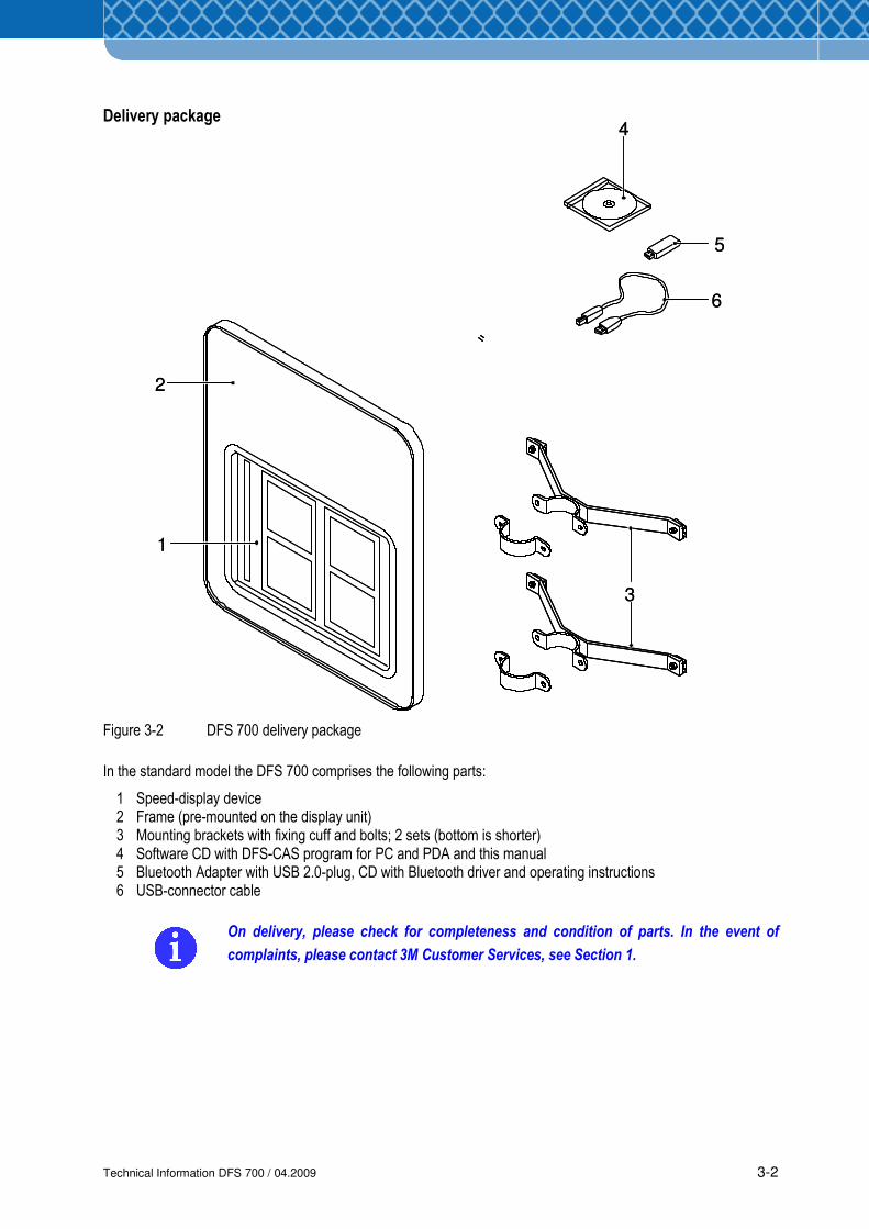
Delivery package
Figure 3-2 DFS 700 delivery package
In the standard model the DFS 700 comprises the following parts:
1 Speed-display device 2 Frame (pre-mounted on the display unit) 3 Mounting brackets with fixing cuff and bolts; 2 sets (bottom is shorter) 4 Software CD with DFS-CAS program for PC and PDA and this manual 5 Bluetooth Adapter with USB 2.0-plug, CD with Bluetooth driver and operating instructions 6 USB-connector cable
On delivery, please check for completeness and condition of parts. In the event of
complaints, please contact 3M Customer Services, see Section 1.
1
2
3
5
4
6
1
2
3
5
4
6
Technical Information DFS 700 / 04.2009 3-3
1
2
3
4
5
4C
4D
4B
4A
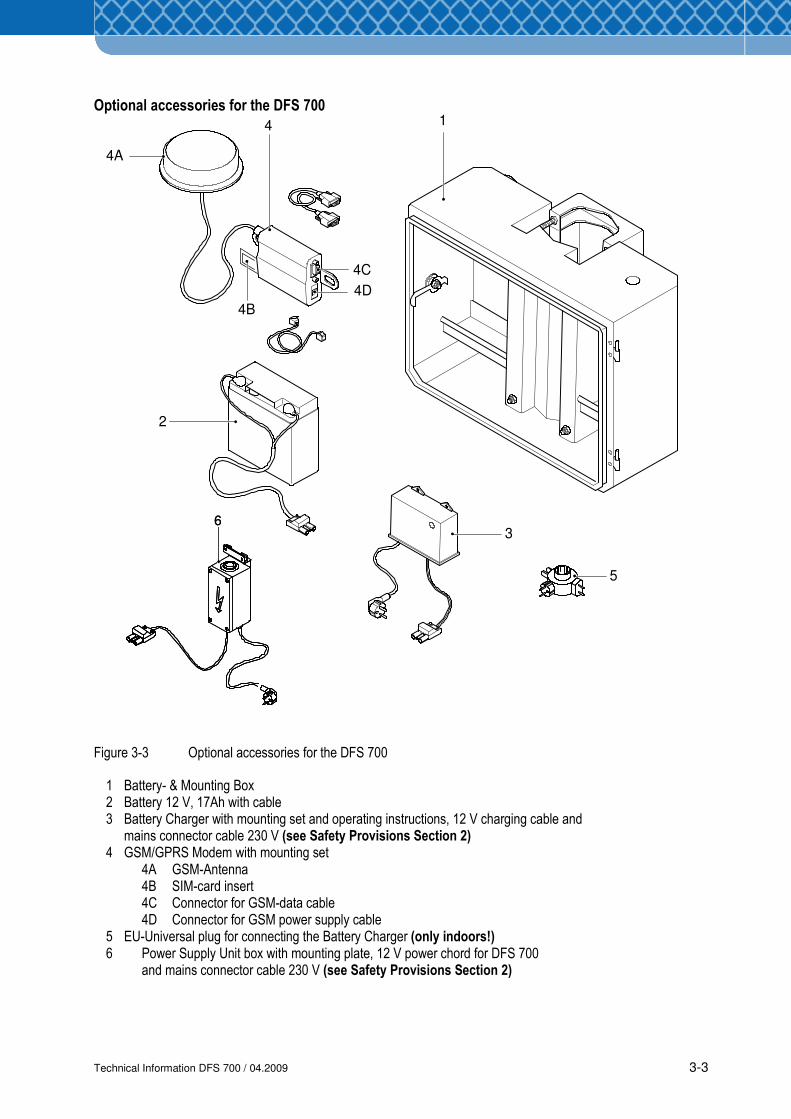
Optional accessories for the DFS 700
Figure 3-3 Optional accessories for the DFS 700
1 Battery- & Mounting Box 2 Battery 12 V, 17Ah with cable 3 Battery Charger with mounting set and operating instructions, 12 V charging cable and mains connector cable 230 V (see Safety Provisions Section 2) 4 GSM/GPRS Modem with mounting set 4A GSM-Antenna 4B SIM-card insert 4C Connector for GSM-data cable 4D Connector for GSM power supply cable 5 EU-Universal plug for connecting the Battery Charger (only indoors!) 6 Power Supply Unit box with mounting plate, 12 V power chord for DFS 700 and mains connector cable 230 V (see Safety Provisions Section 2)
66

Technical Information DFS 700 / 04.2009 3-4
Technical Information DFS 700 / 04.2009 4-1
4 Technical Description
4.1 Intended use
The DFS 700 (Figure 3-1) is used to measure and display the speeds of vehicles driving into
the radar beam. These measurements are displayed to the vehicle, recorded and can be
evaluated statistically by the user program DFS-CAS.
The monitoring of traffic speeds in flowing traffic is particularly usefull for the following traffic
zones:
• Traffic zones with particular speed limits; e.g. residential areas, inner-city areas and
building sites.
• Dangerous traffic spots, such as curves, bridges and tunnels.
• Traffic zones that have to be driven carefully, e.g. in front of hospitals, schools, bus-stops,
streets with surfaces that are dirty or produce noise.
The spray-protected DFS 700 can be used outdoors permanently independent of weather
given the appropriate power supply. As a result of the reflective sheet on the frame (Figure 3-1
Item 1) the DFS 700 can be easily spotted by drivers during the day and especially in the dark
due to reflection from the vehicle's headlamps. If necessary, additional information can be
attached to the reflective area of the frame (Figure 3-1 Item 1).
4.2 Functionality
In the ready-to-use state (power supply created, switched on and initial settings made by the
user program DFS-CAS), the radar sensor (Figure 3-1 Item 4) measures the speed of an
approaching vehicle. The radar sensor (Figure 3-1 Item 4) is located in the lower field of the
central figure.
In normal operation the vehicle’s speed is displayed in LED-digits (Figure 3-1 Item 5) on the
speed display (Figure 3-1 Item 3). The colour of the digits can be set to green or red.
As a rule, speeds set as permissible are displayed in green, speeds exceeding the speed limit
in red.
The LED-digits adapt their intensity to the ambient light conditions.
Technical Information DFS 700 / 04.2009 4-2
A corresponding light sensor (Figure 3-1 Item 2) is located in the upper field of the central
figure.
With two independent thresholds the display can also be set to flashing and an additional
external device, e.g. a flashing warning light, can be switched on for an additional warning
The speed-display unit can store up to 100,000 measurements. If the memory is full additional
measurements will overwrite the oldest measurements first.
All the settings for operation of the speed-display unit are made using the DFS-CAS user
program. The DFS-CAS user program can be installed on a PC running the Windows XP/2000
operating system and/or on a PDA running Windows Mobile 5.0.
The connection from the display unit to the PC is created using the USB-cable supplied
(Figure 3-2 Item 7) or, after activating the supplied Bluetooth adapter (Figure 3-2 Item 6) on
the PC by wireless connection. A Bluetooth-capable PDA can also be connected wireless to
the display unit.
Where the optional GSM-Modem (Figure 3-3 Item 4) is used, additional radio communication
is possible via the GSM network (mobile communication). To that end a modem is needed in
the PC and a GSM-SIM-card (Figure 3-3 Item 4B) is required in the GSM-modem (see also
4.5).
The speed display unit has a 2 1/2 LED digital display, which can display the maximum value
199. It comprises a total of 27 light segments homogenously tuned to each other (13
segments per number, 1 segment for the leading 1). Under optimum environmental conditions
the digits can be read at a distance of over 100 m.
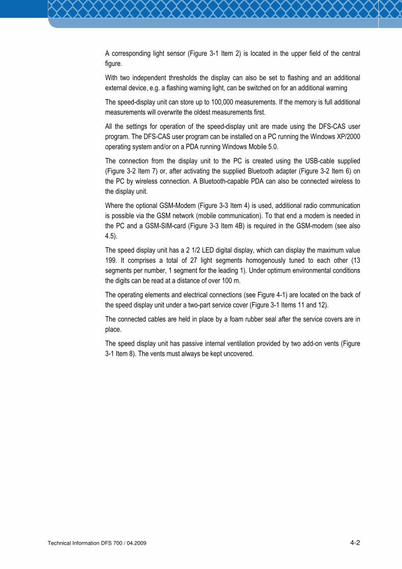
The operating elements and electrical connections (see Figure 4-1) are located on the back of
the speed display unit under a two-part service cover (Figure 3-1 Items 11 and 12).
The connected cables are held in place by a foam rubber seal after the service covers are in
place.
The speed display unit has passive internal ventilation provided by two add-on vents (Figure
3-1 Item 8). The vents must always be kept uncovered.
Technical Information DFS 700 / 04.2009 4-3
1 2 3 4
5
6
7
8
911 10
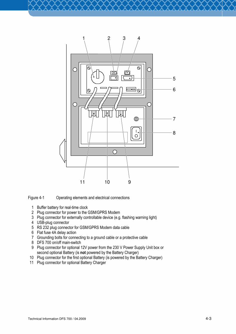
Figure 4-1 Operating elements and electrical connections
1 Buffer battery for real-time clock 2 Plug connector for power to the GSM/GPRS Modem 3 Plug connector for externally controllable device (e.g. flashing warning light) 4 USB-plug connector 5 RS 232 plug connector for GSM/GPRS Modem data cable 6 Flat fuse 4A delay action 7 Grounding bolts for connecting to a ground cable or a protective cable 8 DFS 700 on/off main-switch 9 Plug connector for optional 12V power from the 230 V Power Supply Unit box or second optional Battery (is not powered by the Battery Charger) 10 Plug connector for the first optional Battery (is powered by the Battery Charger) 11 Plug connector for optional Battery Charger
Technical Information DFS 700 / 04.2009 4-4
The speed display unit (Figure 3-1 Item 2) is attached to the frame with screws (Figure 3-1
Item 1). Its breakthrough on the front of the display unit is sealed with black silicone.
The frame can be changed if desired. To that end, eight securing bolts on the speed display
unit casing are to be unscrewed and the silicone seal broken. The new frame is to be bolted
through the same holes and should be sealed with black silicone again.
The optional 230V Power Supply Unit box (Figure 3-1 Item 7) establishes the power supply
between the mains connection (100 V - 240 V) and the speed display unit (12 V) via its two
cables. The box is maintenance-free, weather-tight and not to be opened. The two add-on
vents (Figure 3-1 Item 8) must always be kept free.
As a basic principle, the Power Supply Unit box is to be mounted on its mounting plate above
the speed display unit on the frame.
If required, however, the Power Supply Unit box can also be set up separately considering the
vertical alignment.
The DFS 700 is mounted on a ∅ 60 mm pole via the mounting brackets (Figure 3-1 Item 6).
4.3 Possible applications
The DFS 700 can be used in its standard model and with the optional accessory fittings using
different possible power supplies.
Follow installation advices and electrical connections as specified in Section 6!
• Fixed installation with permanent power supply (mains operation)
The standard model of the DFS 700 is used in a fixed location and is connected to the
public electricity supply through the Power Supply Unit.
Additionally the optional Battery- & Mounting Box can be used for this kind of installation.
• Fixed installation with Battery and mains power supply (Battery buffer mode)
The DFS 700 can be operated with the Battery and the Charger in the Battery- & Mounting
Box. In case the power supply is switched off or fails the equipment is still powered by the
Battery.
The Charger recharges the Battery when the power supply is switched on again.
• Independent Installation (Battery mode)
The DFS 700 can be powered with one or two Batteries in the Battery- & Mounting Box
independent of public power supply. Alternatively, it can also be powered by solar power,
however this is not included in the delivery package of the DFS 700 and must be obtained
from other suppliers.
• Customer-specific Design
After removing the frame (Figure 3-1 Item 1) the speed display unit can be fitted into other
frames or cases, which are equivalent to the original parts in terms of quality
(weatherproofness, ventilation).
NOTE
Technical Information DFS 700 / 04.2009 4-5
4.4 Operating modes
Various modes can be set in the DFS 700 using the user program. The preset red/green
colour change, flashing setting and activation settings for externally connected equipment are
taken into consideration in every mode. The measured speeds are recorded in all operating
modes except for the standby mode.
The speeds to be displayed can be limited such that very slow speeds (e.g. cyclists) or very
high speeds (to avoid abuse) are not displayed.
All modes can be time-scheduled to switch automatically to standby mode and back using a
user-defined switching program, so as to reduce power consumption in periods of low-traffic
density or low-relevance.
• Standby Mode
The DFS 700 operates with minimum power consumption, which only allows the equipment
to be configured using the user program. Radar and Display are inactive.
• Radar Mode
The speeds of approaching vehicles are measured and displayed and the speed data is
stored.
• Limit Mode
Like Radar Mode with the difference that a user-defined speed limit value is displayed to
approaching vehicles.
• Covert Mode
The speeds of approaching vehicles are measured and the data is stored, but nothing is
displayed. This mode enables driven speeds to be collected and assessed without
influencing traffic with a visible display.
• Demo Mode
The LED display shows a sequence of digits with changing red/green colours, varying
brightness and flashing frequency to test the quality and capabilities of the display
presentation.
Technical Information DFS 700 / 04.2009 4-6
4.5 Optional equipment
Power Supply Unit Box
The 230 V power supply unit box (Figure 3-3 Item 6) provides the power supply via its two
cables between the mains connection (100 V - 240 V) and the DFS 700 (12 V). The box is
maintenance-free and waterproof and is not to be opened. The vents must always be kept
clear.
In principle the power supply unit box is to be mounted on the back of the DFS 700. See
Section 6.
If required, the power supply unit box may also be installed separately, taking into account the
vertical alignment.
Battery
The 12 V, 17 Ah Battery (Figure 3-3 Item 2) specially for the DFS 700 is a gel-filled lead
Battery. A cable with a suitable plug is mounted on the Battery poles for connection to the
DFS. Battery and cable are a fixed unit.
Using the Battery mains independent operation is possible.
The voltage management system of the DFS 700 cuts the DFS 700 off from the Battery at a
voltage under 10.8 V so as to avoid deep discharge.
If the optional GSM/GRPS-modem is fitted and active, an error message concerning the
imminent low Battery level is sent by SMS to the specified recipient.
The Battery is safely housed and protected from weather in the optional Battery- & Mounting
Box (Figure 3-3 Item 1).
For separate setup without the Battery- & Mounting Box the Battery must be given
special protection from weather and unauthorised access (see Section 2).
Using Batteries from other manufacturers but with the same performance data is
acceptable. However, 3M will not accept liability for the correct operation of the DFS
700. In any case only the 3M Battery Charger may be used to charge the Batteries
through the DFS 700.
Two identical Batteries can be used to operate the DFS 700; both of them are to be connected
to the speed display unit. The DFS 700 voltage management system will regulate the power
supply from the two batteries and make sure that both are used equally.
NOTE
Technical Information DFS 700 / 04.2009 4-7
Battery Charger
The Battery Charger (Figure 3-3 Item 3) specially for the DFS 700 is only intended to charge
the DFS 700 Battery.
A cable with a suitable plug for connection to the speed display unit is mounted on the Battery
Charger.
Where the Battery Charger is used, buffered mains operation of the DFS 700 is possible.
Therefore a Battery and the optional Battery- & Mounting Box must both be used (Figure 3-3
Item 1).
The Battery is charged by the Charger connected to the mains even if the DFS 700 is
switched off, provided that both the Battery and the Charger are connected to the DFS 700.
For compliance with CE Regulations for fixed installations, where the Charger is
connected to the public mains network, a frequency filter has to be used in the supply
line. Following types can be used:
1. Schurter 5500.2034 FMLB-0109-2040
2. Schurter 5500.2043 FMW2-52-2/1.25
GSM/GPRS-Modem
The GSM/GPRS Modem (Figure 3-3 Item 4) specially for the DFS 700 is a mobile
communication modem for transmissions over any distance.
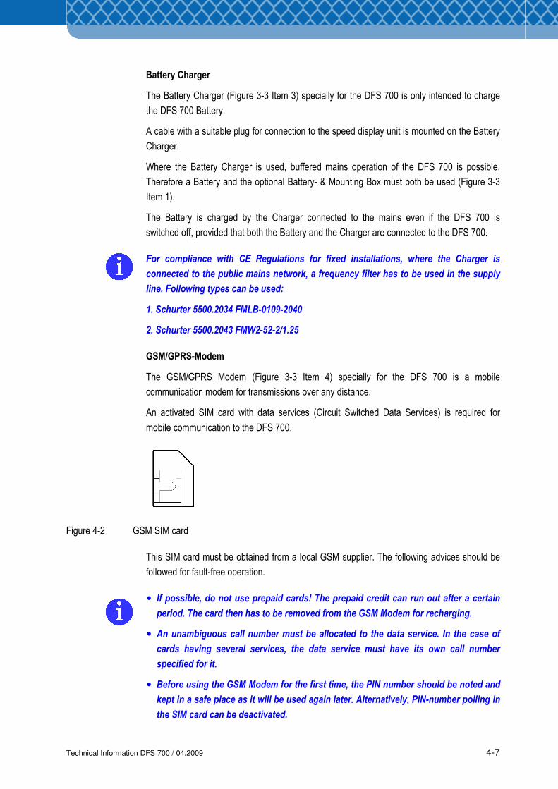
An activated SIM card with data services (Circuit Switched Data Services) is required for
mobile communication to the DFS 700.
Figure 4-2 GSM SIM card
This SIM card must be obtained from a local GSM supplier. The following advices should be
followed for fault-free operation.
• If possible, do not use prepaid cards! The prepaid credit can run out after a certain
period. The card then has to be removed from the GSM Modem for recharging.
• An unambiguous call number must be allocated to the data service. In the case of
cards having several services, the data service must have its own call number
specified for it.
• Before using the GSM Modem for the first time, the PIN number should be noted and
kept in a safe place as it will be used again later. Alternatively, PIN-number polling in
the SIM card can be deactivated.
Technical Information DFS 700 / 04.2009 4-8
ModemTelephone cable
Telephone connection
In the active state the modem transmits error messages/faults to the specified recipient by
SMS.
The activated GSM Modem also represents a alternative connection possiblity to USB or
Bluetooth connections for using the same functions of the software (download data,
diagnostics, etc.).
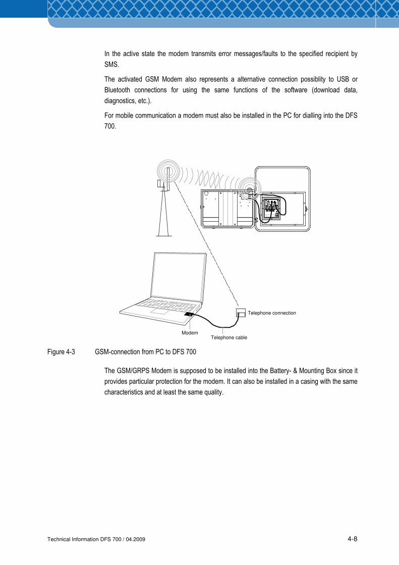
For mobile communication a modem must also be installed in the PC for dialling into the DFS
700.
Figure 4-3 GSM-connection from PC to DFS 700
The GSM/GRPS Modem is supposed to be installed into the Battery- & Mounting Box since it
provides particular protection for the modem. It can also be installed in a casing with the same
characteristics and at least the same quality.
Technical Information DFS 700 / 04.2009 4-9
Battery- & Mounting Box
The Battery- & Mounting Box (Figure 3-3 Item 1) for the DFS 700 is used to store the optional
accessories safely and weatherproof and to mount the device on vertical poles 60 to 140 mm
in diameter.
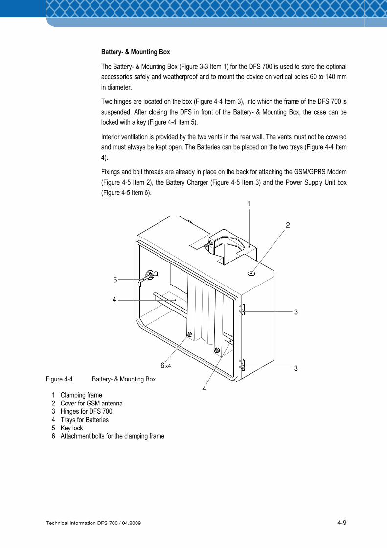
Two hinges are located on the box (Figure 4-4 Item 3), into which the frame of the DFS 700 is
suspended. After closing the DFS in front of the Battery- & Mounting Box, the case can be
locked with a key (Figure 4-4 Item 5).
Interior ventilation is provided by the two vents in the rear wall. The vents must not be covered
and must always be kept open. The Batteries can be placed on the two trays (Figure 4-4 Item
4).
Fixings and bolt threads are already in place on the back for attaching the GSM/GPRS Modem
(Figure 4-5 Item 2), the Battery Charger (Figure 4-5 Item 3) and the Power Supply Unit box
(Figure 4-5 Item 6).
Figure 4-4 Battery- & Mounting Box
1 Clamping frame 2 Cover for GSM antenna 3 Hinges for DFS 700 4 Trays for Batteries 5 Key lock 6 Attachment bolts for the clamping frame
1
2
3
4
3
4
6
5
x4
Technical Information DFS 700 / 04.2009 4-10
1
2
3
4
55
6
7 x2
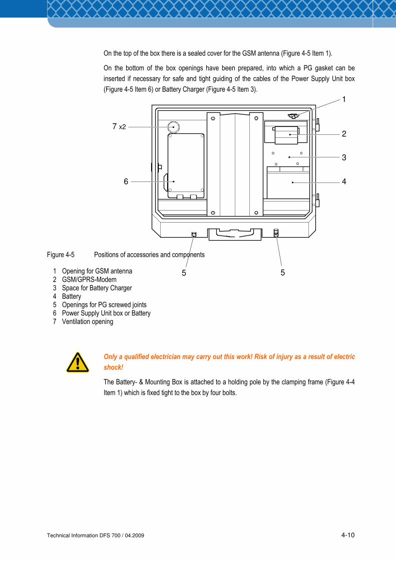
On the top of the box there is a sealed cover for the GSM antenna (Figure 4-5 Item 1).
On the bottom of the box openings have been prepared, into which a PG gasket can be
inserted if necessary for safe and tight guiding of the cables of the Power Supply Unit box
(Figure 4-5 Item 6) or Battery Charger (Figure 4-5 Item 3).
Figure 4-5 Positions of accessories and components
1 Opening for GSM antenna 2 GSM/GPRS-Modem 3 Space for Battery Charger 4 Battery 5 Openings for PG screwed joints 6 Power Supply Unit box or Battery 7 Ventilation opening
Only a qualified electrician may carry out this work! Risk of injury as a result of electric
shock!
The Battery- & Mounting Box is attached to a holding pole by the clamping frame (Figure 4-4
Item 1) which is fixed tight to the box by four bolts.
Technical Information DFS 700 / 04.2009 5-1
5 Transport and Storage
5.1 Transport
For transporting the DFS 700, switched off and disconnected from the mains, and the
accessories the original packaging should always be used. If the DFS 700 and the Battery- &
Mounting Box are to be transported already assembled, a break-proof and weatherproof
packing should be made for this unit. In addition, the front of the frame is to be protected by a
soft cover.
For transport all outward-leading cables are to be laid such that they cannot hang loose.
The Battery must be removed from the Battery- & Mounting Box prior to transport and packed
separately.
Follow safety advices on handling the Battery, see Section 2.
During transport do not hit the parts or subject them to strong vibration.
5.2 Storage
The DFS and its accessories, switched off and disconnected from the mains, can be stored for
up to 12 months at an ambient temperature of 20°C to 30°C and 55% relative humidity in a
dry room.
Follow safety advices on storage of Batteries, see Section 2.

Technical Information DFS 700 / 04.2009 5-2
Technical Information DFS 700 / 04.2009 6-1
1
2
2
3
or/and
Preliminaries
Configurationwith PC
Configurationwith PC and PDA
Operation
PC
CDDFS-CAS
Windows 2000/XP
PC
CDDFS-CASWindows Mobile
Power
Power
PDA
PDA
USB
USBDriver
USB
Bluetooth
BluetoothDriver
Power
6 Preparation and Configuration
6.1 Overview of first comissioning
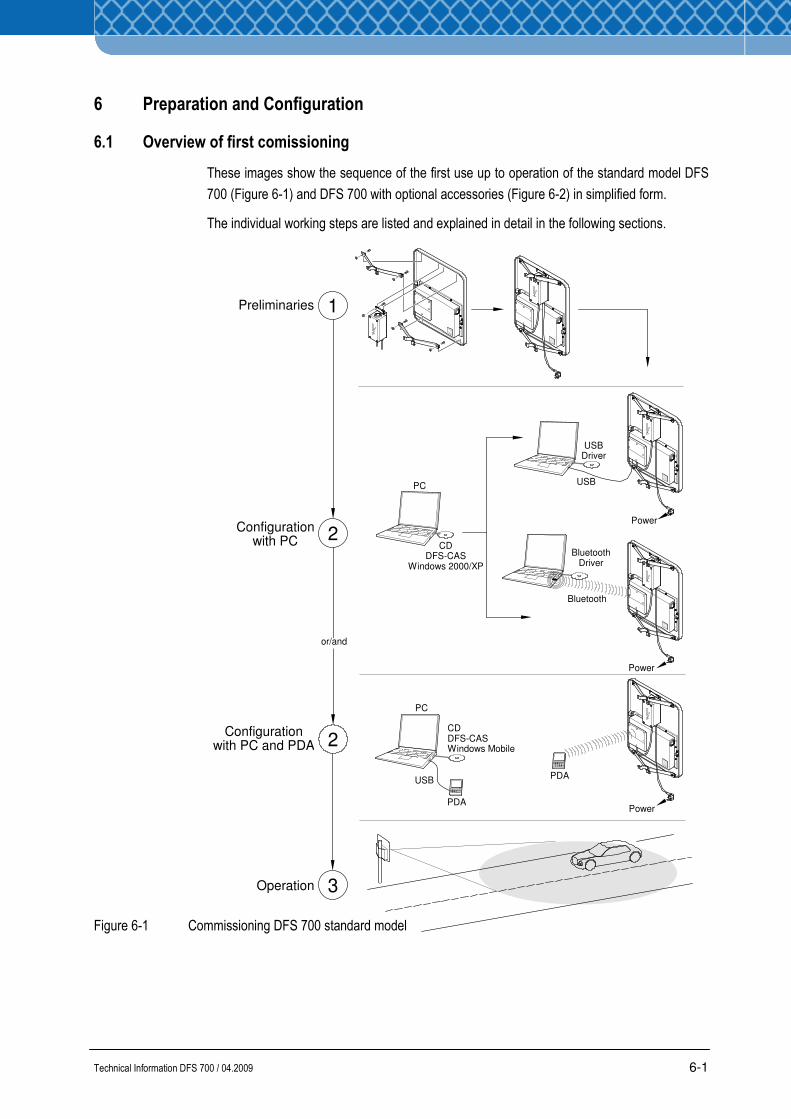
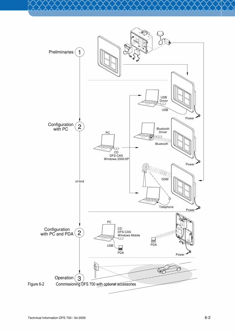
These images show the sequence of the first use up to operation of the standard model DFS
700 (Figure 6-1) and DFS 700 with optional accessories (Figure 6-2) in simplified form.
The individual working steps are listed and explained in detail in the following sections.
Figure 6-1 Commissioning DFS 700 standard model
Technical Information DFS 700 / 04.2009 6-2
1
2
USB
2
3
PC
CDDFS-CAS
Windows 2000/XP
PDA
GSM
Bluetooth
BluetoothDriver
Telephone
PC
CDDFS-CASWindows Mobile
PDAUSB
or/and
Preliminaries
Configurationwith PC
Configurationwith PC and PDA
Operation
Power
Power
Power
Power
USBDriver
Figure 6-2 Commissioning DFS 700 with optional accessories
Technical Information DFS 700 / 04.2009 6-3
1
2
3
4
6
7
8
2
3
2
3
4
3
2
x2
x2
5
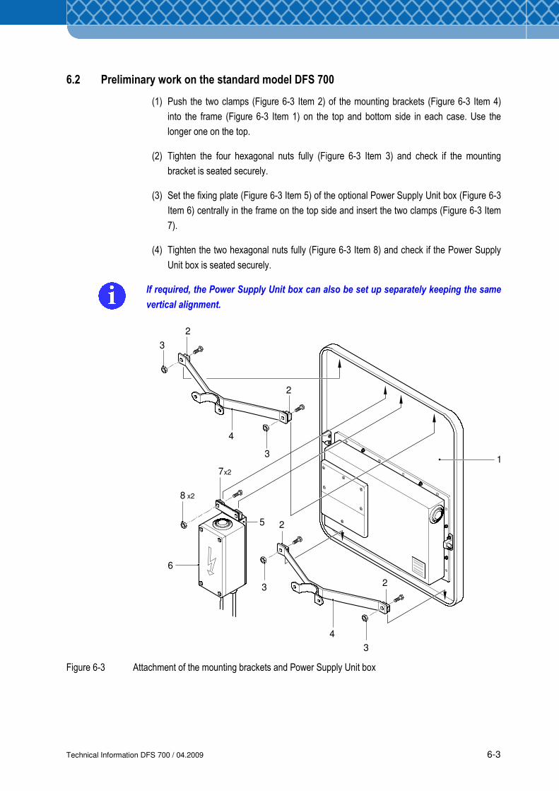
6.2 Preliminary work on the standard model DFS 700
(1) Push the two clamps (Figure 6-3 Item 2) of the mounting brackets (Figure 6-3 Item 4)
into the frame (Figure 6-3 Item 1) on the top and bottom side in each case. Use the
longer one on the top.
(2) Tighten the four hexagonal nuts fully (Figure 6-3 Item 3) and check if the mounting
bracket is seated securely.
(3) Set the fixing plate (Figure 6-3 Item 5) of the optional Power Supply Unit box (Figure 6-3
Item 6) centrally in the frame on the top side and insert the two clamps (Figure 6-3 Item
7).
(4) Tighten the two hexagonal nuts fully (Figure 6-3 Item 8) and check if the Power Supply
Unit box is seated securely.
If required, the Power Supply Unit box can also be set up separately keeping the same
vertical alignment.
Figure 6-3 Attachment of the mounting brackets and Power Supply Unit box
Technical Information DFS 700 / 04.2009 6-4
2 x2
4
5
3
1
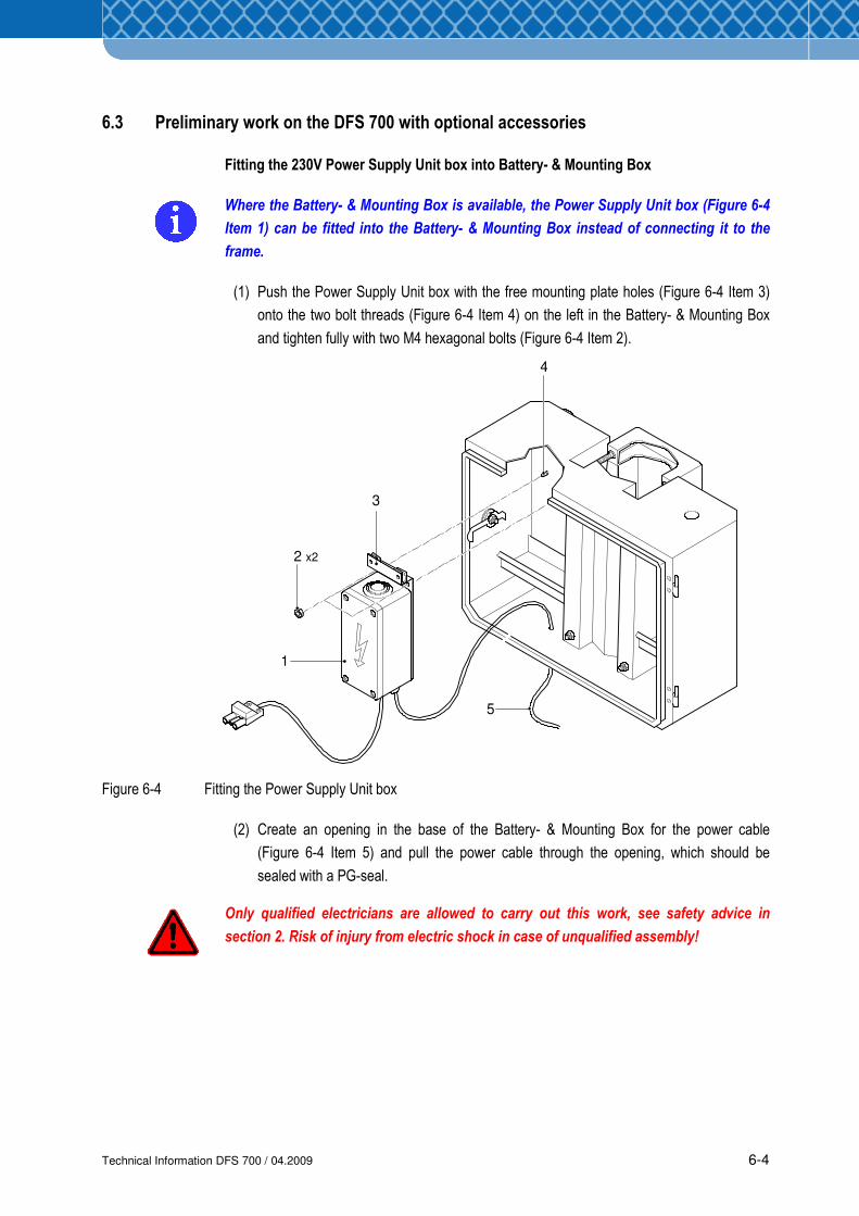
6.3 Preliminary work on the DFS 700 with optional accessories
Fitting the 230V Power Supply Unit box into Battery- & Mounting Box
Where the Battery- & Mounting Box is available, the Power Supply Unit box (Figure 6-4
Item 1) can be fitted into the Battery- & Mounting Box instead of connecting it to the
frame.
(1) Push the Power Supply Unit box with the free mounting plate holes (Figure 6-4 Item 3)
onto the two bolt threads (Figure 6-4 Item 4) on the left in the Battery- & Mounting Box
and tighten fully with two M4 hexagonal bolts (Figure 6-4 Item 2).
Figure 6-4 Fitting the Power Supply Unit box
(2) Create an opening in the base of the Battery- & Mounting Box for the power cable
(Figure 6-4 Item 5) and pull the power cable through the opening, which should be
sealed with a PG-seal.
Only qualified electricians are allowed to carry out this work, see safety advice in
section 2. Risk of injury from electric shock in case of unqualified assembly!
Technical Information DFS 700 / 04.2009 6-5
2
1x2
3
4
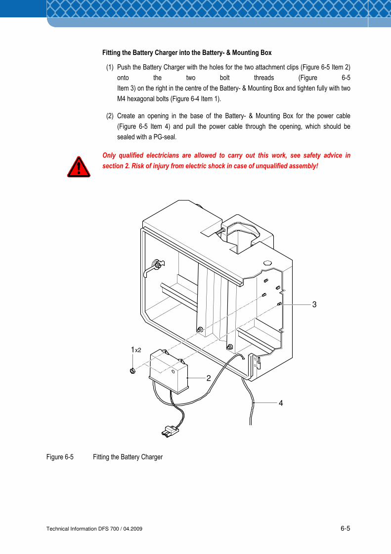
Fitting the Battery Charger into the Battery- & Mounting Box
(1) Push the Battery Charger with the holes for the two attachment clips (Figure 6-5 Item 2)
onto the two bolt threads (Figure 6-5
Item 3) on the right in the centre of the Battery- & Mounting Box and tighten fully with two
M4 hexagonal bolts (Figure 6-4 Item 1).
(2) Create an opening in the base of the Battery- & Mounting Box for the power cable
(Figure 6-5 Item 4) and pull the power cable through the opening, which should be
sealed with a PG-seal.
Only qualified electricians are allowed to carry out this work, see safety advice in
section 2. Risk of injury from electric shock in case of unqualified assembly!
Figure 6-5 Fitting the Battery Charger
Technical Information DFS 700 / 04.2009 6-6
x2
6
7
8
9
1
1
2
2
3
4
5
10
11
12
13
14
15
16
x2
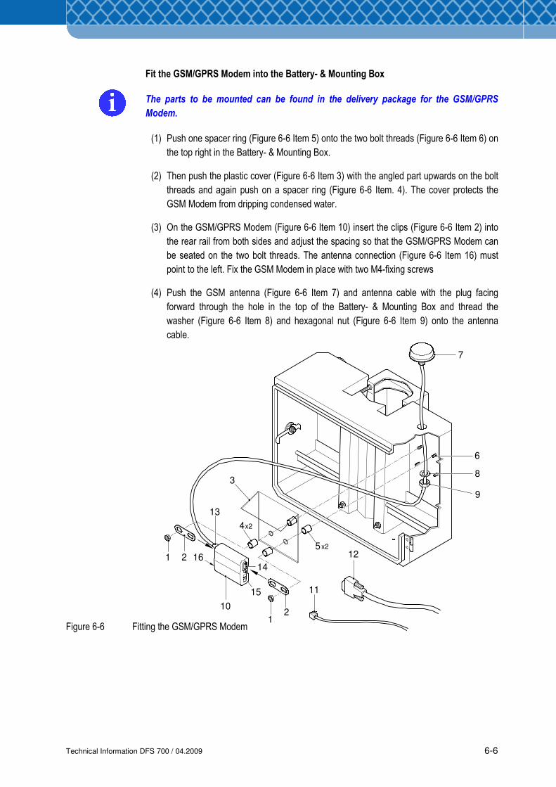
Fit the GSM/GPRS Modem into the Battery- & Mounting Box
The parts to be mounted can be found in the delivery package for the GSM/GPRS
Modem.
(1) Push one spacer ring (Figure 6-6 Item 5) onto the two bolt threads (Figure 6-6 Item 6) on
the top right in the Battery- & Mounting Box.
(2) Then push the plastic cover (Figure 6-6 Item 3) with the angled part upwards on the bolt
threads and again push on a spacer ring (Figure 6-6 Item. 4). The cover protects the
GSM Modem from dripping condensed water.
(3) On the GSM/GPRS Modem (Figure 6-6 Item 10) insert the clips (Figure 6-6 Item 2) into
the rear rail from both sides and adjust the spacing so that the GSM/GPRS Modem can
be seated on the two bolt threads. The antenna connection (Figure 6-6 Item 16) must
point to the left. Fix the GSM Modem in place with two M4-fixing screws
(4) Push the GSM antenna (Figure 6-6 Item 7) and antenna cable with the plug facing
forward through the hole in the top of the Battery- & Mounting Box and thread the
washer (Figure 6-6 Item 8) and hexagonal nut (Figure 6-6 Item 9) onto the antenna
cable.
Figure 6-6 Fitting the GSM/GPRS Modem
Technical Information DFS 700 / 04.2009 6-7
(5) Tighten the antenna head (Figure 6-6 Item 7) from inside with the hexagonal nut (Figure
6-6 Item 9). Ensure that the washer (Figure 6-6 Item 8) fully covers the hole from the
inside.
(6) Screw the antenna cable tightly to the antenna connection (Figure 6-6 Item 13).
(7) Screw the data cable (Figure 6-6 Item 12) to the RS 232 interface (Figure 6-6 Item 14).
(8) Plug the power cable to the DFS 700 into the socket (Figure 6-6 Item 15).
(9) Collect excess cable and tie off with cable ties.
(10) Insert an activated GSM data SIM card into the SIM card holder (Figure 6-6 Item 16) in
the GSM/GPRS Modem and lock it.
See Section 4.5 for information on the SIM card to be used. NOTE
Technical Information DFS 700 / 04.2009 6-8
6.4 Configuring the DFS 700 with a PC
All settings on the DFS 700 are made using the supplied DFS-CAS PC program. This program
is used to perform configuration and data analysis. Furthermore, diagnostic info and traffic
data can also be retrieved.
6.4.1 Install the DFS-CAS program
Minimum requirements
• PC with Intel Pentium III processor
• 256 MB RAM memory
• Display-/ Monitor resolution 1024x768
• CD-ROM drive
• USB (or Bluetooth) port
• 50 MB free disk space
• Windows 2000 SP4 or Windows XP SP2 operating system
• Internet Explorer 5.0.
Installation
(1) Insert the program CD in the drive - the Setup program starts automatically.
(2) Select “Install DFS-CAS for Windows“ or select “Start” then “Run” from the Windows
taskbar and enter the path to the CD ROM drive and the setup program file name, e.g.
“d:\setup.exe”, to open it
(3) Click “OK” to confirm. The program is installed, in doing so follow the installation
instructions.
(4) Once installation is complete the program can be started by the new symbol on the
desktop or by selecting it via the “Programs” menu.
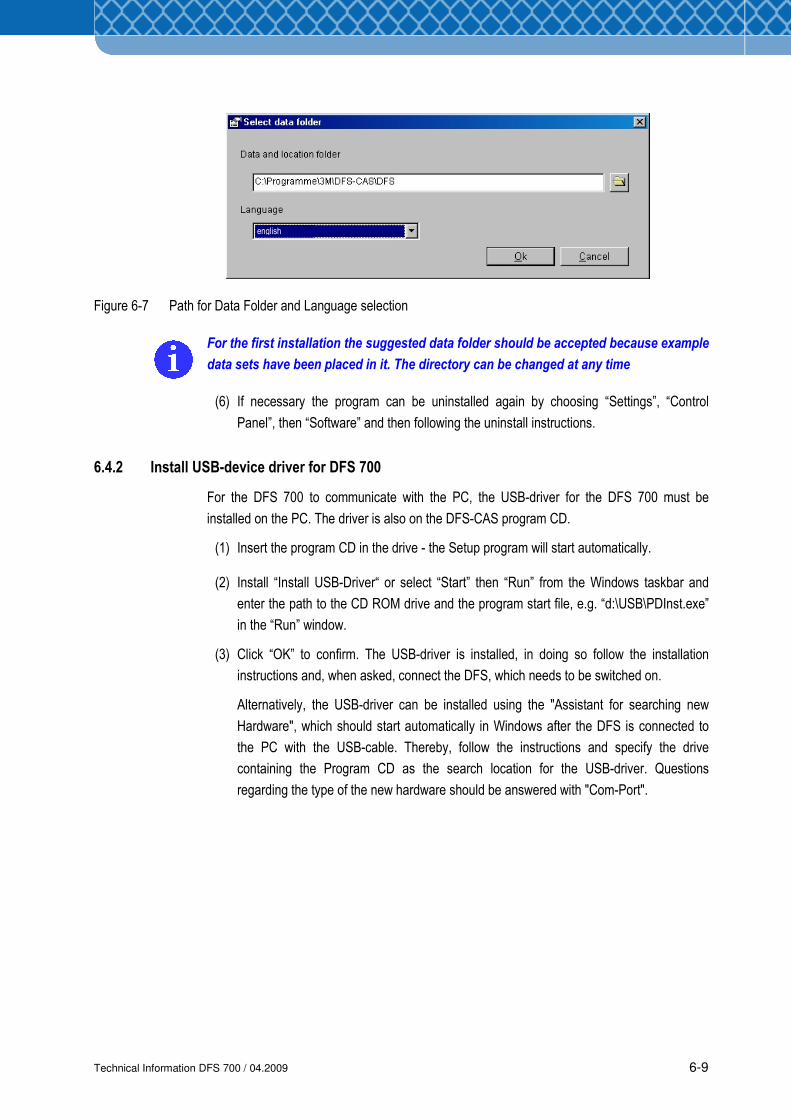
(5) After the first start a window appears (Figure 6-7), in which the path for the data folder
and the desired language can be selected in advance.
Technical Information DFS 700 / 04.2009 6-9
Figure 6-7 Path for Data Folder and Language selection
For the first installation the suggested data folder should be accepted because example
data sets have been placed in it. The directory can be changed at any time
(6) If necessary the program can be uninstalled again by choosing “Settings”, “Control
Panel”, then “Software” and then following the uninstall instructions.
6.4.2 Install USB-device driver for DFS 700
For the DFS 700 to communicate with the PC, the USB-driver for the DFS 700 must be
installed on the PC. The driver is also on the DFS-CAS program CD.
(1) Insert the program CD in the drive - the Setup program will start automatically.
(2) Install “Install USB-Driver“ or select “Start” then “Run” from the Windows taskbar and
enter the path to the CD ROM drive and the program start file, e.g. “d:\USB\PDInst.exe”
in the “Run” window.
(3) Click “OK” to confirm. The USB-driver is installed, in doing so follow the installation
instructions and, when asked, connect the DFS, which needs to be switched on.
Alternatively, the USB-driver can be installed using the "Assistant for searching new
Hardware", which should start automatically in Windows after the DFS is connected to
the PC with the USB-cable. Thereby, follow the instructions and specify the drive
containing the Program CD as the search location for the USB-driver. Questions
regarding the type of the new hardware should be answered with "Com-Port".
english
Technical Information DFS 700 / 04.2009 6-10
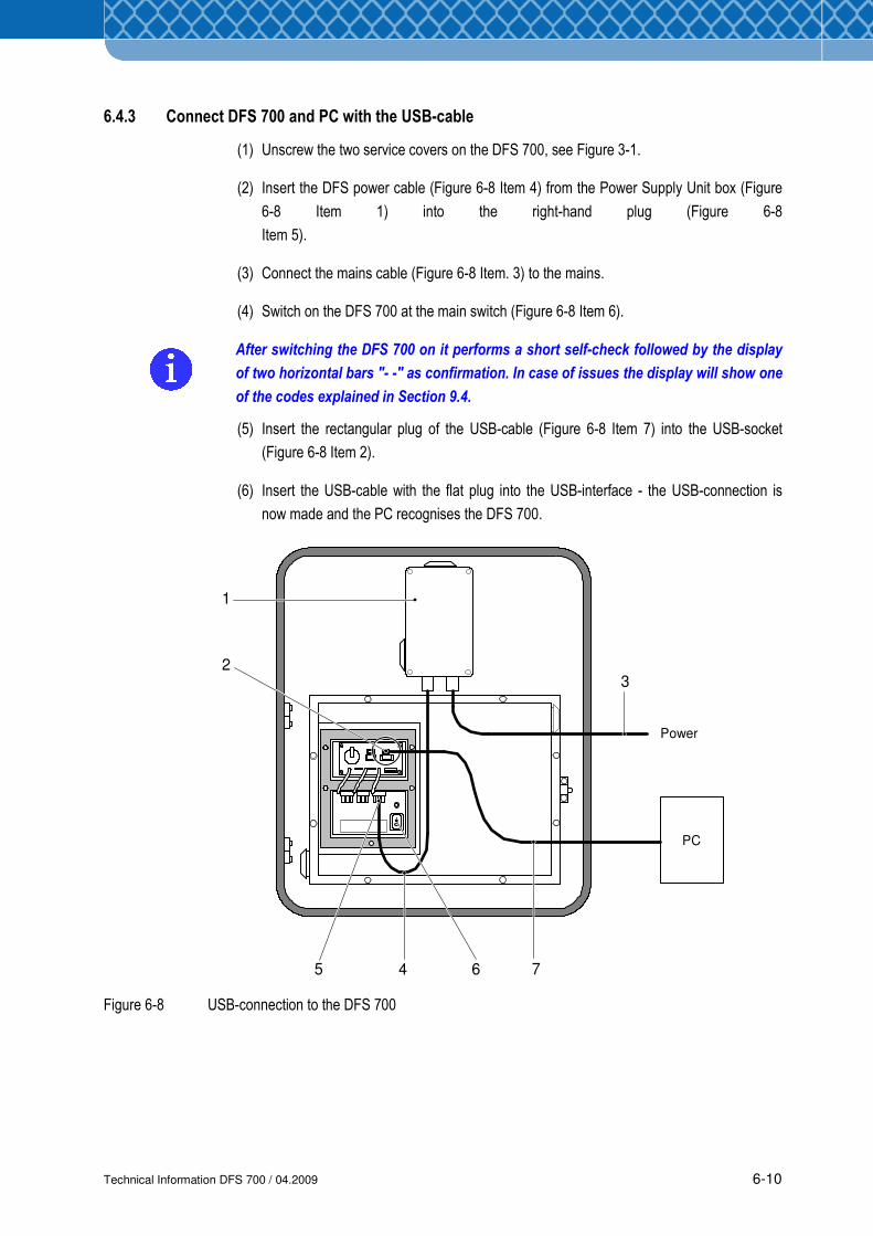
6.4.3 Connect DFS 700 and PC with the USB-cable
(1) Unscrew the two service covers on the DFS 700, see Figure 3-1.
(2) Insert the DFS power cable (Figure 6-8 Item 4) from the Power Supply Unit box (Figure
6-8 Item 1) into the right-hand plug (Figure 6-8
Item 5).
(3) Connect the mains cable (Figure 6-8 Item. 3) to the mains.
(4) Switch on the DFS 700 at the main switch (Figure 6-8 Item 6).
After switching the DFS 700 on it performs a short self-check followed by the display
of two horizontal bars "- -" as confirmation. In case of issues the display will show one
of the codes explained in Section 9.4.
(5) Insert the rectangular plug of the USB-cable (Figure 6-8 Item 7) into the USB-socket
(Figure 6-8 Item 2).
(6) Insert the USB-cable with the flat plug into the USB-interface - the USB-connection is
now made and the PC recognises the DFS 700.
Figure 6-8 USB-connection to the DFS 700
PC
1
23
45 6 7
Power
Technical Information DFS 700 / 04.2009 6-11
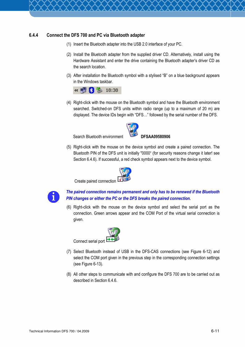
6.4.4 Connect the DFS 700 and PC via Bluetooth adapter
(1) Insert the Bluetooth adapter into the USB 2.0 interface of your PC.
(2) Install the Bluetooth adapter from the supplied driver CD. Alternatively, install using the
Hardware Assistant and enter the drive containing the Bluetooth adapter’s driver CD as
the search location.
(3) After installation the Bluetooth symbol with a stylised “B” on a blue background appears
in the Windows taskbar.
(4) Right-click with the mouse on the Bluetooth symbol and have the Bluetooth environment
searched. Switched-on DFS units within radio range (up to a maximum of 20 m) are
displayed. The device IDs begin with “DFS…” followed by the serial number of the DFS.
Search Bluetooth environment DFSAA09580906
(5) Right-click with the mouse on the device symbol and create a paired connection. The
Bluetooth PIN of the DFS unit is initially "0000“ (for security reasons change it later! see
Section 6.4.6). If successful, a red check symbol appears next to the device symbol.
Create paired connection
The paired connection remains permanent and only has to be renewed if the Bluetooth
PIN changes or either the PC or the DFS breaks the paired connection.
(6) Right-click with the mouse on the device symbol and select the serial port as the
connection. Green arrows appear and the COM Port of the virtual serial connection is
given.
Connect serial port
(7) Select Bluetooth instead of USB in the DFS-CAS connections (see Figure 6-12) and
select the COM port given in the previous step in the corresponding connection settings
(see Figure 6-13).
(8) All other steps to communicate with and configure the DFS 700 are to be carried out as
described in Section 6.4.6.
Technical Information DFS 700 / 04.2009 6-12
6.4.5 Connect the DFS 700 and PC via GSM
(1) Connect a modem to the PC and then connect the modem to a suitable
telecommunication line (e.g. analogue or ISDN)
(2) Connect the optional GSM Modem to the DFS 700 (see Section 6.3) and insert a GSM
data SIM card (see Section 4.5).
(3) Select a connection for the modem connected to the PC in the DFS-CAS connections
(see Figure 6-12).
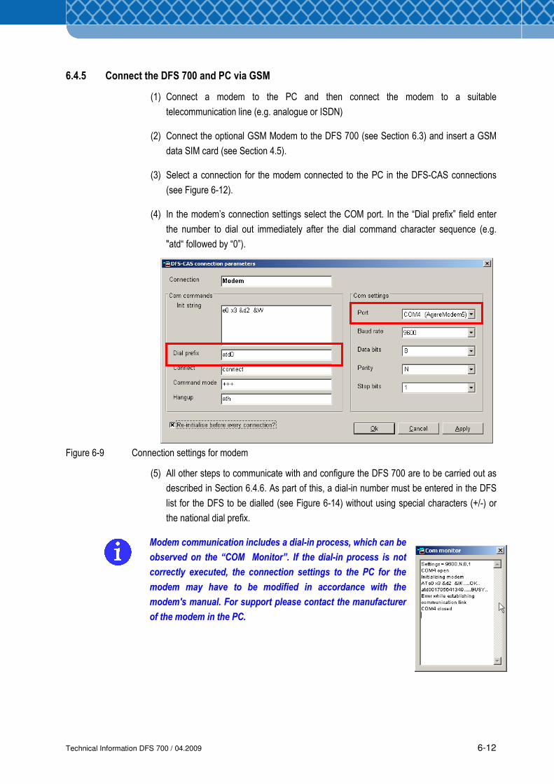
(4) In the modem’s connection settings select the COM port. In the “Dial prefix” field enter
the number to dial out immediately after the dial command character sequence (e.g.
"atd“ followed by “0”).
Figure 6-9 Connection settings for modem
(5) All other steps to communicate with and configure the DFS 700 are to be carried out as
described in Section 6.4.6. As part of this, a dial-in number must be entered in the DFS
list for the DFS to be dialled (see Figure 6-14) without using special characters (+/-) or
the national dial prefix.
Modem communication includes a dial-in process, which can be
observed on the “COM Monitor”. If the dial-in process is not
correctly executed, the connection settings to the PC for the
modem may have to be modified in accordance with the
modem's manual. For support please contact the manufacturer
of the modem in the PC.
Technical Information DFS 700 / 04.2009 6-13
6.4.6 Set up the DFS 700 with the DFS-CAS program
The DFS-CAS program has a help function, which can be called via the “F1” key or the
“?” in the menu bar. The help subjects aid with installation, the configuration of the
DFS and analysis of speed data.
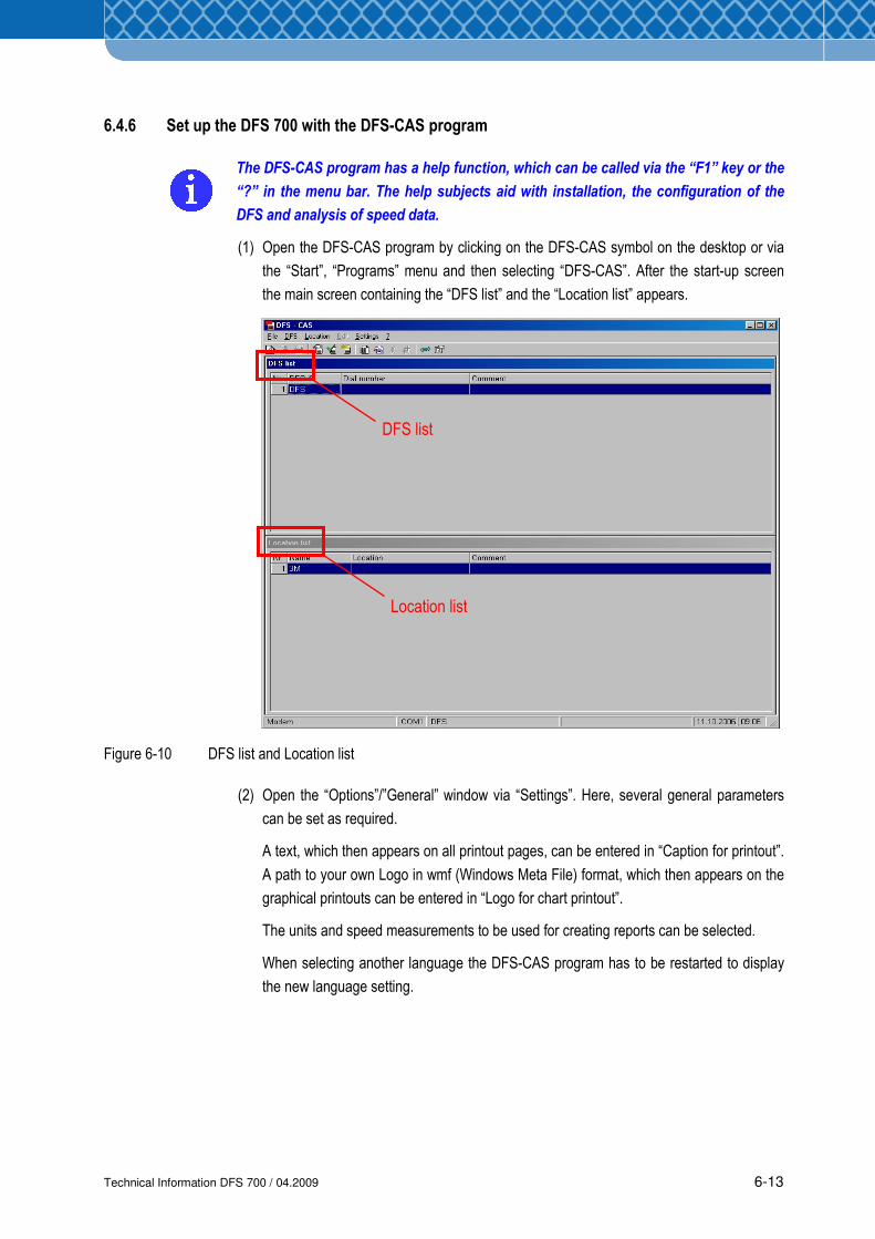
(1) Open the DFS-CAS program by clicking on the DFS-CAS symbol on the desktop or via
the “Start”, “Programs” menu and then selecting “DFS-CAS”. After the start-up screen
the main screen containing the “DFS list” and the “Location list” appears.
Figure 6-10 DFS list and Location list
(2) Open the “Options”/”General” window via “Settings”. Here, several general parameters
can be set as required.
A text, which then appears on all printout pages, can be entered in “Caption for printout”.
A path to your own Logo in wmf (Windows Meta File) format, which then appears on the
graphical printouts can be entered in “Logo for chart printout”.
The units and speed measurements to be used for creating reports can be selected.
When selecting another language the DFS-CAS program has to be restarted to display
the new language setting.
DFS list
Location list
Technical Information DFS 700 / 04.2009 6-14
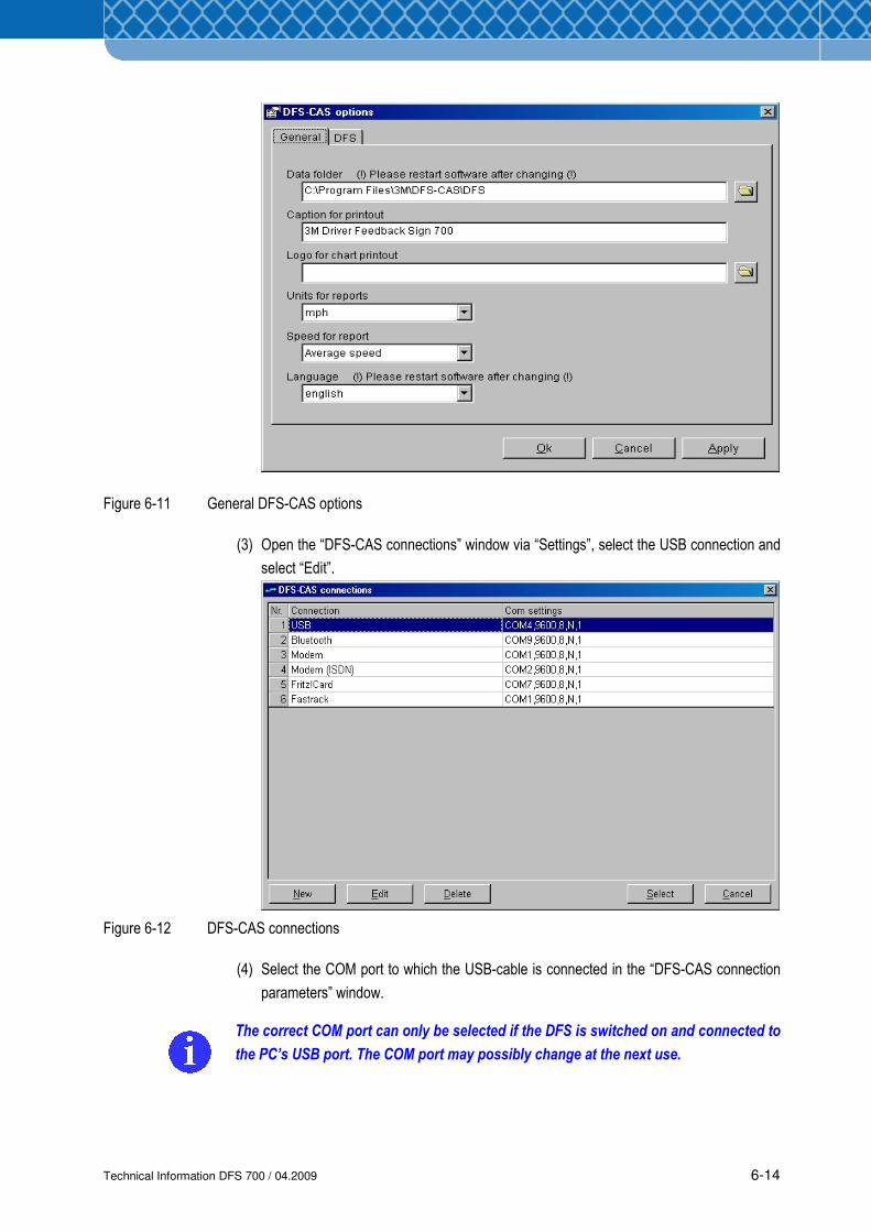
Figure 6-11 General DFS-CAS options
(3) Open the “DFS-CAS connections” window via “Settings”, select the USB connection and
select “Edit”.
Figure 6-12 DFS-CAS connections
(4) Select the COM port to which the USB-cable is connected in the “DFS-CAS connection
parameters” window.
The correct COM port can only be selected if the DFS is switched on and connected to
the PC’s USB port. The COM port may possibly change at the next use.
Technical Information DFS 700 / 04.2009 6-15
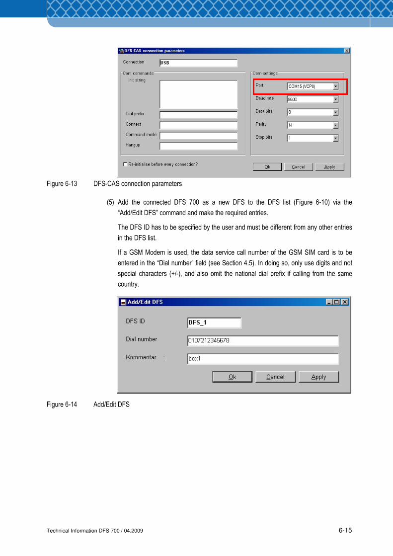
Figure 6-13 DFS-CAS connection parameters
(5) Add the connected DFS 700 as a new DFS to the DFS list (Figure 6-10) via the
“Add/Edit DFS” command and make the required entries.
The DFS ID has to be specified by the user and must be different from any other entries
in the DFS list.
If a GSM Modem is used, the data service call number of the GSM SIM card is to be
entered in the “Dial number” field (see Section 4.5). In doing so, only use digits and not
special characters (+/-), and also omit the national dial prefix if calling from the same
country.
Figure 6-14 Add/Edit DFS
COM15 (VCP0)
Technical Information DFS 700 / 04.2009 6-16
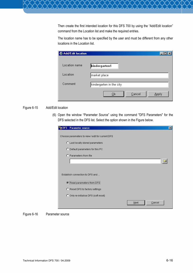
Then create the first intended location for this DFS 700 by using the “Add/Edit location”
command from the Location list and make the required entries.
The location name has to be specified by the user and must be different from any other
locations in the Location list.
Figure 6-15 Add/Edit location
(6) Open the window “Parameter Source” using the command "DFS Parameters" for the
DFS selected in the DFS list. Select the option shown in the Figure below.
Figure 6-16 Parameter source
Technical Information DFS 700 / 04.2009 6-17
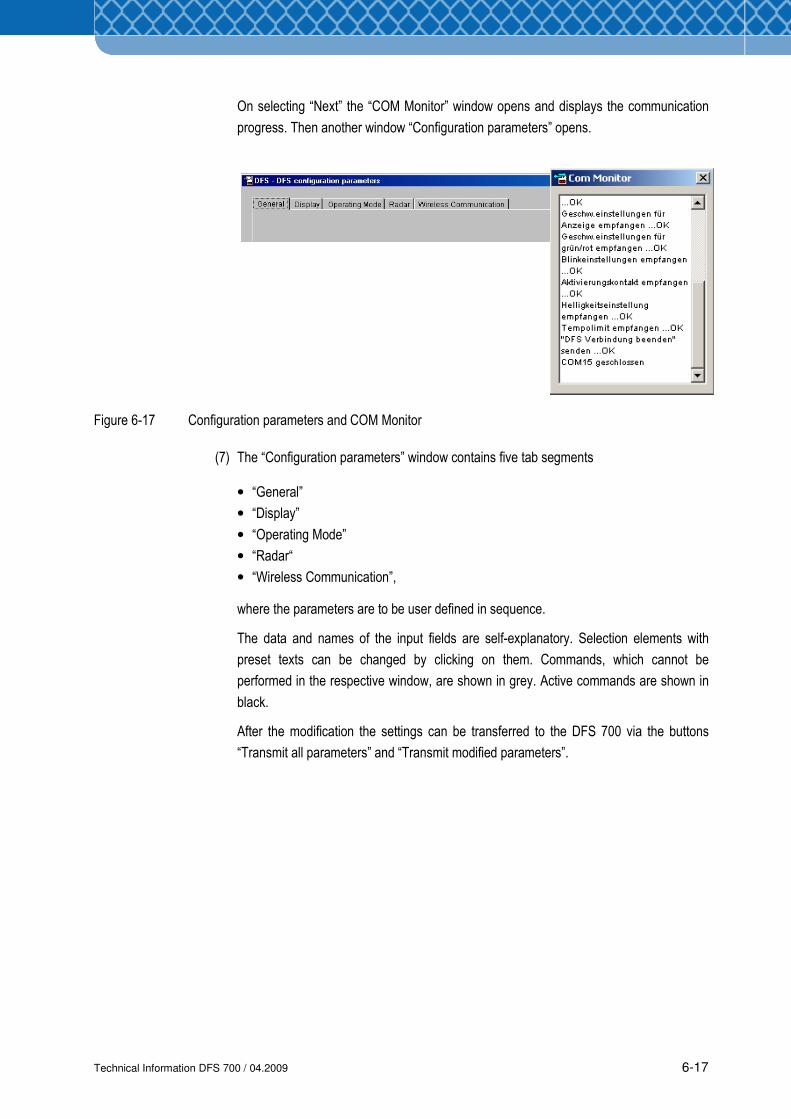
On selecting “Next” the “COM Monitor” window opens and displays the communication
progress. Then another window “Configuration parameters” opens.
Figure 6-17 Configuration parameters and COM Monitor
(7) The “Configuration parameters” window contains five tab segments
• “General”
• “Display”
• “Operating Mode”
• “Radar“
• “Wireless Communication”,
where the parameters are to be user defined in sequence.
The data and names of the input fields are self-explanatory. Selection elements with
preset texts can be changed by clicking on them. Commands, which cannot be
performed in the respective window, are shown in grey. Active commands are shown in
black.
After the modification the settings can be transferred to the DFS 700 via the buttons
“Transmit all parameters” and “Transmit modified parameters”.
Technical Information DFS 700 / 04.2009 6-18
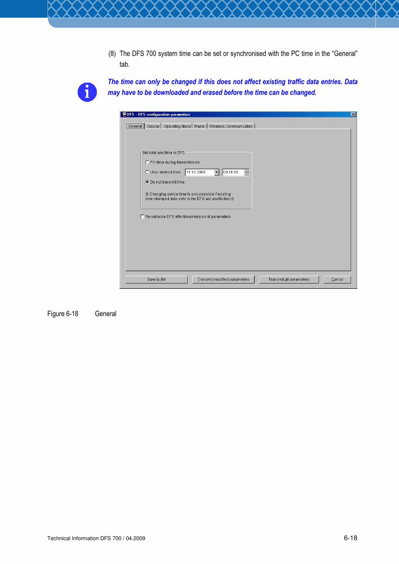
(8) The DFS 700 system time can be set or synchronised with the PC time in the “General”
tab.
The time can only be changed if this does not affect existing traffic data entries. Data
may have to be downloaded and erased before the time can be changed.
Figure 6-18 General
Technical Information DFS 700 / 04.2009 6-19
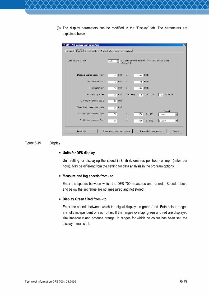
(9) The display parameters can be modified in the “Display” tab. The parameters are
explained below.
Figure 6-19 Display
• Units for DFS display
Unit setting for displaying the speed in km/h (kilometres per hour) or mph (miles per
hour). May be different from the setting for data analysis in the program options.
• Measure and log speeds from - to
Enter the speeds between which the DFS 700 measures and records. Speeds above
and below the set range are not measured and not stored.
• Display Green / Red from - to
Enter the speeds between which the digital displays in green / red. Both colour ranges
are fully independent of each other. If the ranges overlap, green and red are displayed
simultaneously and produce orange. In ranges for which no colour has been set, the
display remains off.
Technical Information DFS 700 / 04.2009 6-20
To prevent abuse like intentional speeeding, the colour ranges should be set such that
no display occurs above a specific speed. Measurements will still be stored if they are
within the defined measurement range
• Start flashing above
Speed above which the digital display also flashes
• Frequency on/off
Flashing on- and off-time intervals in tenths of a second
• Activate switchgear above
Speed above which an externally controlled unit, e.g. flashing warning light, is switched
on
• Show this in speed limit mode
Speed value to be displayed in the “Speed Limit” mode (e.g. the maximum permissible
speed)
In order to display the speed limit only above a certain speed the colour range has to
be set accordingly. For example, if the unit is supposed to display a red 50 above
speeds of 55 km/h, then the following settings are suitable:
- Measure from 3 to 198 (measure and store all)
- Green from 199 to 199 (is never displayed!)
- Red from 55 to 199 (activate red above 55 km/h)
- Display in speed-limit mode 50 (display 50)
• Green / Red brightness range from - to
The minimum and maximum brightness limits for display of the green/red LED’s
dependent on ambient light or selection of the presets "Economic", "Normal" and
"Intense". Within these limits the DFS adapts the brightness of the display to the ambient
light, whereby 255 stands for 100% brightness. At daytime the brightness will be at
maximum and at night at minimum.
Technical Information DFS 700 / 04.2009 6-21
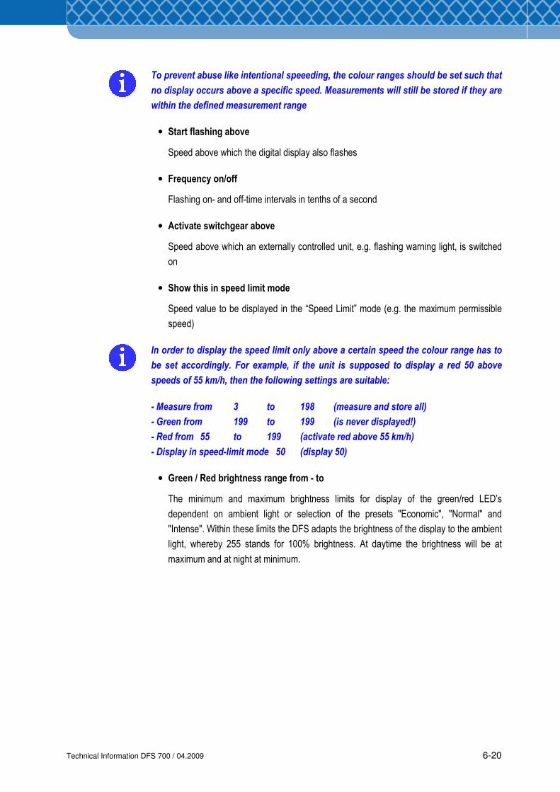
(10) The operating mode can be selected in the “Operating Mode” tab (see also Section 4.4)
and times for automatic switching between the selected mode and the Standby mode
can be scheduled
Figure 6-20 Operating Mode
The following modes are possible (see also Section 4.4):
• Standby Mode Communication only
• Radar Mode Display the currently measured speed
• Covert Mode Store the speed only. No display
• Limit Mode Display a fixed value (e.g. speed limit)
• Demo Mode Display random numbers
All 27 possible switching programs are deactivated on delivery and can be configured as
required. Thereby, days, times and change to Standby mode or the selected mode can be
defined. In case no switching time is defined and activated the DFS will always be working in
the selected mode.
Technical Information DFS 700 / 04.2009 6-22
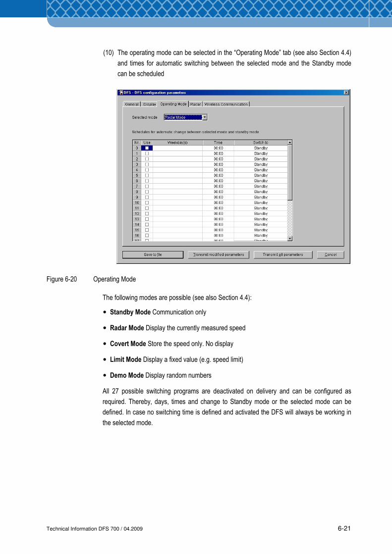
(11) The radar sensitivity can be set as required in the “Radar” tab. The maximum setting
(255) is advisable. Reducing the sensitivity is only recommended in the case of faulty
measurements caused by adverse ambient conditions.
Figure 6-21 Radar
Technical Information DFS 700 / 04.2009 6-23
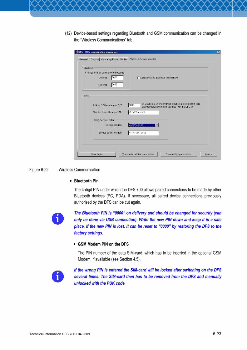
(12) Device-based settings regarding Bluetooth and GSM communication can be changed in
the “Wireless Communications” tab.
Figure 6-22 Wireless Communication
• Bluetooth Pin
The 4-digit PIN under which the DFS 700 allows paired connections to be made by other
Bluetooth devices (PC, PDA). If necessary, all paired device connections previously
authorised by the DFS can be cut again.
The Bluetooth PIN is “0000” on delivery and should be changed for security (can
only be done via USB connection). Write the new PIN down and keep it in a safe
place. If the new PIN is lost, it can be reset to “0000” by restoring the DFS to the
factory settings.
• GSM Modem PIN on the DFS
The PIN number of the data SIM-card, which has to be inserted in the optional GSM
Modem, if available (see Section 4.5).
If the wrong PIN is entered the SIM-card will be locked after switching on the DFS
several times. The SIM-card then has to be removed from the DFS and manually
unlocked with the PUK code.
Technical Information DFS 700 / 04.2009 6-24
• Number for SMS Message
Mobile phone number to which the SMS messages are to be sent. This only functions
if the optional GSM Modem is available and a data SIM-card is inserted (see Section
4.5). The following messages are sent in English text:
• Battery almost empty
• Data memory almost full
• Data memory full. Oldest traffic data will be overwritten
• Battery of real-time clock empty
• Status code in the event of issues (Self-test every 24 hours, see chapter 9.4)
• SMS Service Centre
Enter the SMS Service Centre call number of the mobile-phone operator who supplied
the data SIM-card (see Section 4.5)
(13) The DFS 700 is now ready for use. As a simple function test, an open hand can be
waved quickly past the radar sensor of the DFS 700 - if the speed display is set low
enough the speed of the hand will be displayed.
(14) Switch off the DFS 700, unplug the mains cable and the power supply cable, pull out the
USB-cable and refit the service covers. The DFS can be transported to where it will be
set up.
Technical Information DFS 700 / 04.2009 6-25
6.5 Configuring the DFS 700 with a PDA
All the settings on the DFS 700 can also be made using the supplied PDA-program DFS-CAS.
Communication and data transfer between the PDA and the DFS 700 is wireless (Bluetooth).
Moreover, the PDA software can be used to diagnose faults in the DFS 700 and download
traffic data for the subsequent tranfer and analysis on the PC.
6.5.1 Install PDA program
PDA Requirements
• Windows Mobile 5.0 operating system
• Bluetooth
• Display-/Monitor resolution 240 x 230
• Microsoft .Net Compact Framework 2.0 SP1.
PC Requirements
• PC with Intel Pentium III
• CD-ROM drive
• Windows 2000 SP4 or
Windows XP SP2 operating system
• Internet Explorer 5.0
• Display-/Monitor resolution 1024 x 768
• Microsoft Active SynC 4.2 (or higher)
• 20 MB free disk space
• At least 256 MB RAM working memory.
Installation
(1) Insert the program CD in the CD-ROM drive – the Setup program then runs
automatically.
(2) Select “Install DFS-CAS for Windows Mobile“ or select “Start” then “Run” from the
Windows taskbar and enter the path to the CD ROM drive and the setup program file,
e.g. “d:\PDA\Setup.exe”
(3) Click “OK” to confirm. The program is installed, in doing so follow the installation
instructions.
(4) Once installation is complete the program can be started by using the new symbol on the
desktop or by selecting it via the “Programs” menu.
Technical Information DFS 700 / 04.2009 6-26
(5) The program can be uninstalled by calling “Settings”, “System Control”, then “Software”
and then following the uninstall instructions.
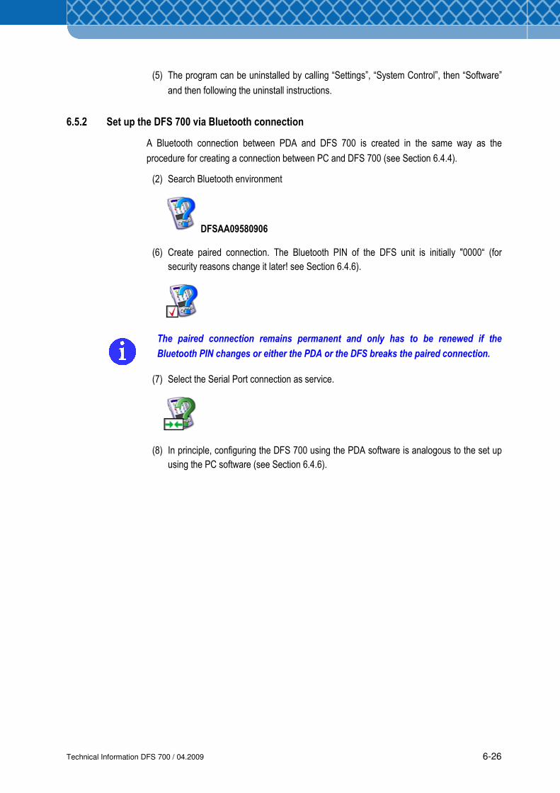
6.5.2 Set up the DFS 700 via Bluetooth connection
A Bluetooth connection between PDA and DFS 700 is created in the same way as the
procedure for creating a connection between PC and DFS 700 (see Section 6.4.4).
(2) Search Bluetooth environment
DFSAA09580906
(6) Create paired connection. The Bluetooth PIN of the DFS unit is initially "0000“ (for
security reasons change it later! see Section 6.4.6).
The paired connection remains permanent and only has to be renewed if the
Bluetooth PIN changes or either the PDA or the DFS breaks the paired connection.
(7) Select the Serial Port connection as service.
(8) In principle, configuring the DFS 700 using the PDA software is analogous to the set up
using the PC software (see Section 6.4.6).
Technical Information DFS 700 / 04.2009 7-1
7 Installation and Operation
7.1 Selecting the installation location for DFS 700
To ensure correct measurements the location for the DFS 700 must be selected according to
the following criteria:
• There must be an unobstructed visual field of at least 150 metres in front of the DFS 700. In
this area and in the radar beam there must be no objects such as trees, poles, parking
vehicles etc. Otherwise the speed display may be falsified and the radar range reduced.
Trees, in particular reduce the radar range
• The location of the DFS 700 must be at least 65 metres away from large traffic signs.
Otherwise these large traffic signs can reflect the radar beams such that the vehicles in the
opposite lane could be recorded by the radar beam.
• Do not set the DFS 700 up directly at crossing intersections or bridges. The DFS 700 must
be at least 125 metres away from crossing traffic, as it could otherwise also record the
crossing traffic as oncoming vehicles.
• Where solar cells are used for powering the DFS, the location must have an unhindered
view of the sky to achieve the highest charge-capacity. Trees and buildings can cast
shadows on solar panels and therefore greatly reduce the performance of the solar cells.
• The environment around the optional GSM antenna must be kept free of metallic objects so
as to guarantee optimum data transfer over the mobile phone network.
Technical Information DFS 700 / 04.2009 7-2
1
2
3
4
5
5
6
2
4
5
1
3
x2
x2
x2
x2
x2
x2
7.2 Mounting the DFS 700
This section describes how to mount the DFS at the designated location.
Pay particular attention to safety advices as specified in Section 2.
To avoid danger from flowing traffic the location should be secured, see Section 2
Safety Hints.
As a basic principle, this work can be done by one person. For tightening, only
commercially available tools are required.
7.2.1 Standard model DFS 700
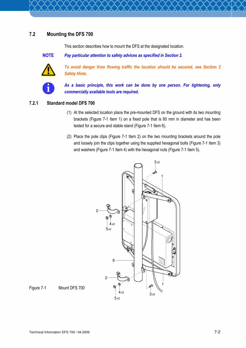
(1) At the selected location place the pre-mounted DFS on the ground with its two mounting
brackets (Figure 7-1 Item 1) on a fixed pole that is 60 mm in diameter and has been
tested for a secure and stable stand (Figure 7-1 Item 6).
(2) Place the pole clips (Figure 7-1 Item 2) on the two mounting brackets around the pole
and loosely join the clips together using the supplied hexagonal bolts (Figure 7-1 Item 3)
and washers (Figure 7-1 Item 4) with the hexagonal nuts (Figure 7-1 Item 5).
Figure 7-1 Mount DFS 700
NOTE
Technical Information DFS 700 / 04.2009 7-3
2m
max. 10°
24°
14°
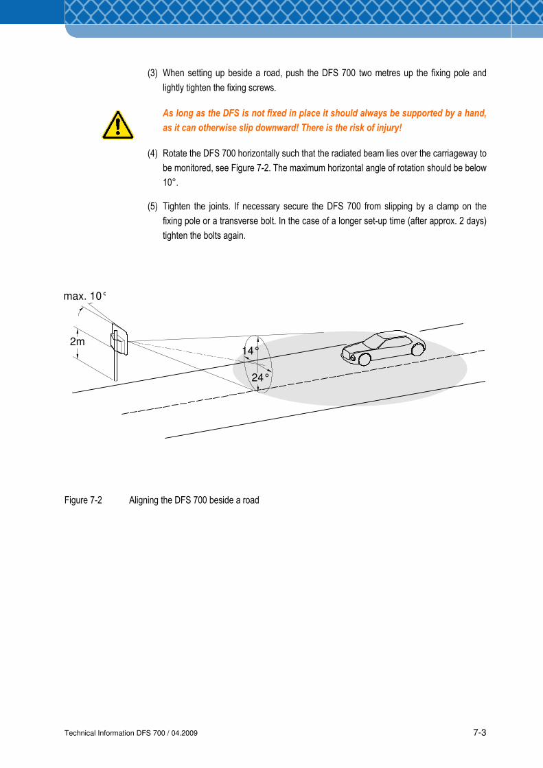
(3) When setting up beside a road, push the DFS 700 two metres up the fixing pole and
lightly tighten the fixing screws.
As long as the DFS is not fixed in place it should always be supported by a hand,
as it can otherwise slip downward! There is the risk of injury!
(4) Rotate the DFS 700 horizontally such that the radiated beam lies over the carriageway to
be monitored, see Figure 7-2. The maximum horizontal angle of rotation should be below
10°.
(5) Tighten the joints. If necessary secure the DFS 700 from slipping by a clamp on the
fixing pole or a transverse bolt. In the case of a longer set-up time (after approx. 2 days)
tighten the bolts again.
Figure 7-2 Aligning the DFS 700 beside a road
Technical Information DFS 700 / 04.2009 7-4
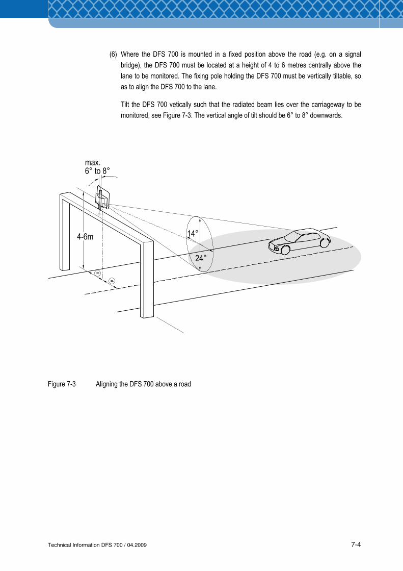
(6) Where the DFS 700 is mounted in a fixed position above the road (e.g. on a signal
bridge), the DFS 700 must be located at a height of 4 to 6 metres centrally above the
lane to be monitored. The fixing pole holding the DFS 700 must be vertically tiltable, so
as to align the DFS 700 to the lane.
Tilt the DFS 700 vetically such that the radiated beam lies over the carriageway to be
monitored, see Figure 7-3. The vertical angle of tilt should be 6° to 8° downwards.
Figure 7-3 Aligning the DFS 700 above a road
4-6m
max. 6° to 8°
24°
14°
Technical Information DFS 700 / 04.2009 7-5
1
2 3
45
x4
x2
1x2
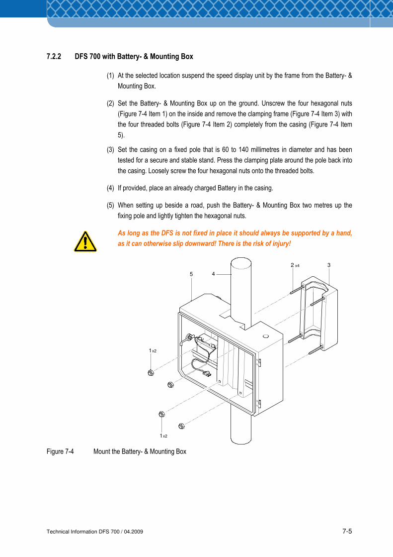
7.2.2 DFS 700 with Battery- & Mounting Box
(1) At the selected location suspend the speed display unit by the frame from the Battery- &
Mounting Box.
(2) Set the Battery- & Mounting Box up on the ground. Unscrew the four hexagonal nuts
(Figure 7-4 Item 1) on the inside and remove the clamping frame (Figure 7-4 Item 3) with
the four threaded bolts (Figure 7-4 Item 2) completely from the casing (Figure 7-4 Item
5).
(3) Set the casing on a fixed pole that is 60 to 140 millimetres in diameter and has been
tested for a secure and stable stand. Press the clamping plate around the pole back into
the casing. Loosely screw the four hexagonal nuts onto the threaded bolts.
(4) If provided, place an already charged Battery in the casing.
(5) When setting up beside a road, push the Battery- & Mounting Box two metres up the
fixing pole and lightly tighten the hexagonal nuts.
As long as the DFS is not fixed in place it should always be supported by a hand,
as it can otherwise slip downward! There is the risk of injury!
Figure 7-4 Mount the Battery- & Mounting Box
Technical Information DFS 700 / 04.2009 7-6
1
3
2
(6) Rotate the Battery- & Mounting Box horizontally such that - with the display unit
subsequently in place - the radiated beam lies over the carriageway to be monitored, see
Figure 7-2. The maximum horizontal angle of rotation should be below 10°. If necessary
secure the Battery- & Mounting Box from slipping by a clamp on the fixing pole or a
transverse bolt. In the case of a longer set-up time (after approx. 2 days), tighten the
fixings again.
(7) Where the Battery- & Mounting Box is mounted in a fixed position above the road (e.g.
on a signal bridge), it must be located centrally at a height of 4 to 6 metres above the
lane to be monitored. The fixing pole holding the mounted Battery- & Mounting Box must
be vertically tiltable, so as to align the DFS 700 with the lane.
Tilt the box vertically such that the radiated beam lies over the carriageway to be
monitored, see Figure 7-3. The vertical angle of tilt should be 6° to 8° downwards.
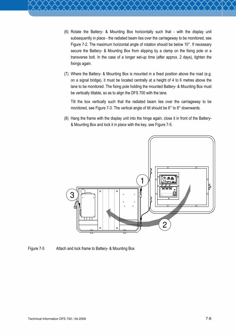
(8) Hang the frame with the display unit into the hinge again, close it in front of the Battery-
& Mounting Box and lock it in place with the key, see Figure 7-5.
Figure 7-5 Attach and lock frame to Battery- & Mounting Box
Technical Information DFS 700 / 04.2009 7-7
7.3 Connecting and switching electrical power
This section describes the different options for providing the necessary power for operating the
DFS 700.
To connect the DFS 700 to the public power supply outdoors, a connection must be
available that satisfies the local electrical guidelines and safety requirements.
The power supply line phase [brown/black wire] must be secured with a suitable fuse,
typically 4 to 6 A. Otherwise the electronics in the DFS 700 may be damaged or
destroyed in case of over-current.
When the DFS 700 is in a fixed installation, e.g. to street lights, a disconnectable over-
current protective device (max. 6A) according to EN60950 must be installed between
the power supply line and the DFS 700. For service work on the DFS 700 the power
supply must be disconnected via the over-current protective device.
The over-current protective device is to be installed in accordance with the local
electrical guidelines and safety requirements. Therefore in Scandinavia, for example, a
cut out must have a 2-pole connection against grounding.
The electrical connections must always be produced in accordance with the
requirements for the intended location. In the case of fixed installations the plug on the
power supply unit or the Charger may have to be removed. If the plug is still to be used,
then an adequately waterproof, weather-resistant, and properly mounted socket with
protection to the power line as specified above is to be provided.
Pay particular attention to further safety advices specified in Section 2.
For compliance with CE Regulations for fixed installations, where the Charger is
connected to the public mains network, a frequency filter has to be used in the supply
line. Following types can be used:
1. Schurter 5500.2034 FMLB-0109-2040
2. Schurter 5500.2043 FMW2-52-2/1.25
NOTE
Technical Information DFS 700 / 04.2009 7-8
1
2
35 4
Power
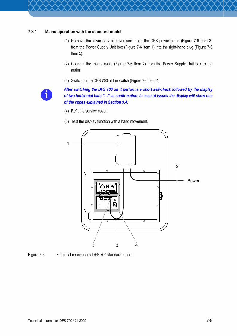
7.3.1 Mains operation with the standard model
(1) Remove the lower service cover and insert the DFS power cable (Figure 7-6 Item 3)
from the Power Supply Unit box (Figure 7-6 Item 1) into the right-hand plug (Figure 7-6
Item 5).
(2) Connect the mains cable (Figure 7-6 Item 2) from the Power Supply Unit box to the
mains.
(3) Switch on the DFS 700 at the switch (Figure 7-6 Item 4).
After switching the DFS 700 on it performs a short self-check followed by the display
of two horizontal bars "- -" as confirmation. In case of issues the display will show one
of the codes explained in Section 9.4.
(4) Refit the service cover.
(5) Test the display function with a hand movement.
Figure 7-6 Electrical connections DFS 700 standard model
Technical Information DFS 700 / 04.2009 7-9
1
Power
7.3.2 Mains operation using Battery- & Mounting Box
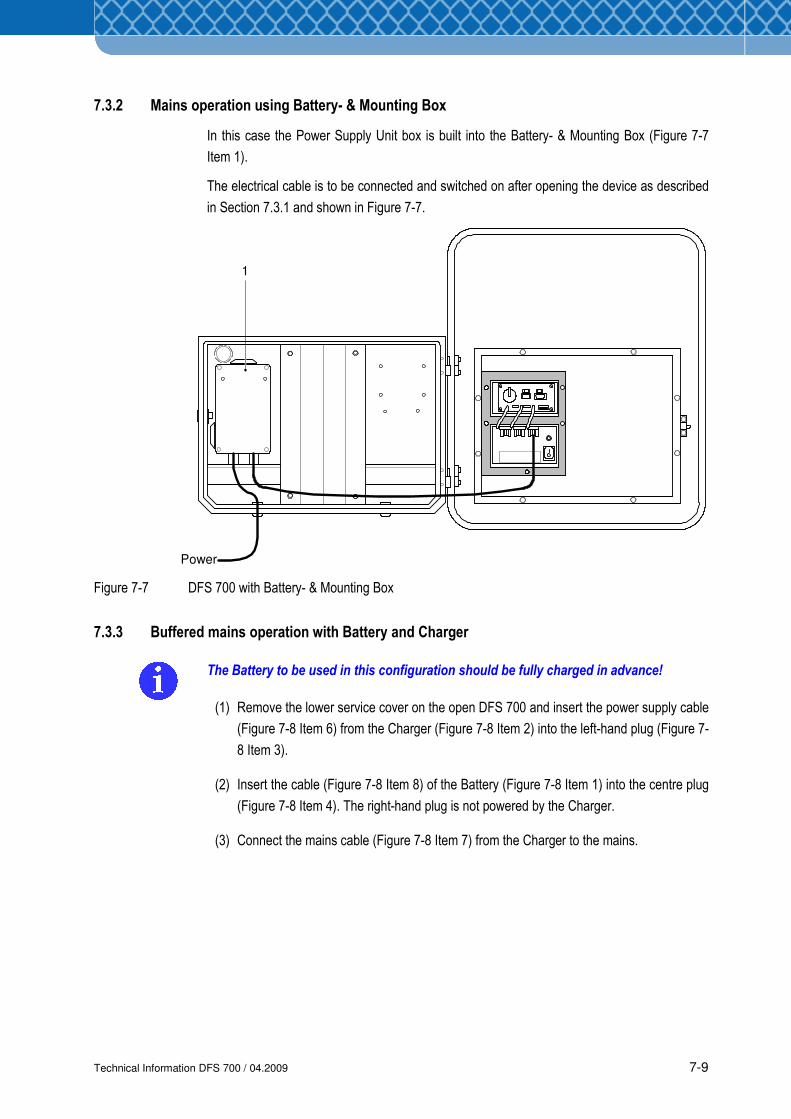
In this case the Power Supply Unit box is built into the Battery- & Mounting Box (Figure 7-7
Item 1).
The electrical cable is to be connected and switched on after opening the device as described
in Section 7.3.1 and shown in Figure 7-7.
Figure 7-7 DFS 700 with Battery- & Mounting Box
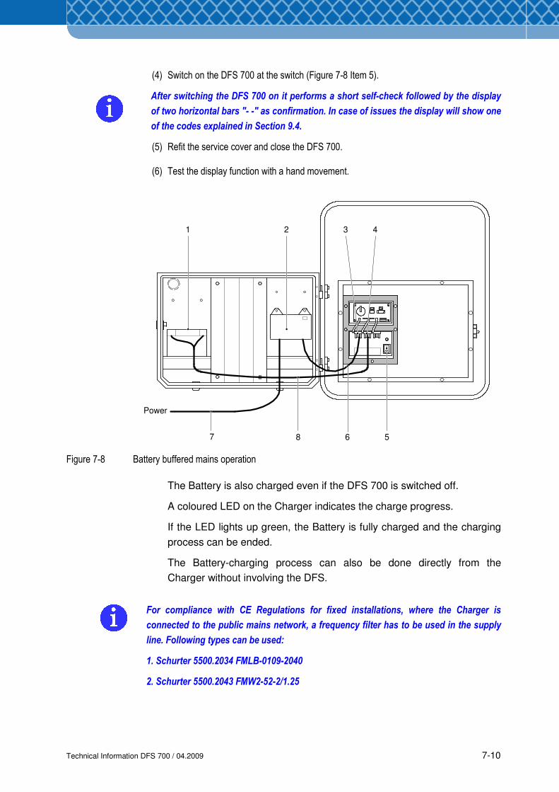
7.3.3 Buffered mains operation with Battery and Charger
The Battery to be used in this configuration should be fully charged in advance!
(1) Remove the lower service cover on the open DFS 700 and insert the power supply cable
(Figure 7-8 Item 6) from the Charger (Figure 7-8 Item 2) into the left-hand plug (Figure 7-
8 Item 3).
(2) Insert the cable (Figure 7-8 Item 8) of the Battery (Figure 7-8 Item 1) into the centre plug
(Figure 7-8 Item 4). The right-hand plug is not powered by the Charger.
(3) Connect the mains cable (Figure 7-8 Item 7) from the Charger to the mains.
Technical Information DFS 700 / 04.2009 7-10
1 2 3 4
567 8
Power
(4) Switch on the DFS 700 at the switch (Figure 7-8 Item 5).
After switching the DFS 700 on it performs a short self-check followed by the display
of two horizontal bars "- -" as confirmation. In case of issues the display will show one
of the codes explained in Section 9.4.
(5) Refit the service cover and close the DFS 700.
(6) Test the display function with a hand movement.
Figure 7-8 Battery buffered mains operation
The Battery is also charged even if the DFS 700 is switched off.
A coloured LED on the Charger indicates the charge progress.
If the LED lights up green, the Battery is fully charged and the charging
process can be ended.
The Battery-charging process can also be done directly from the
Charger without involving the DFS.
For compliance with CE Regulations for fixed installations, where the Charger is
connected to the public mains network, a frequency filter has to be used in the supply
line. Following types can be used:
1. Schurter 5500.2034 FMLB-0109-2040
2. Schurter 5500.2043 FMW2-52-2/1.25
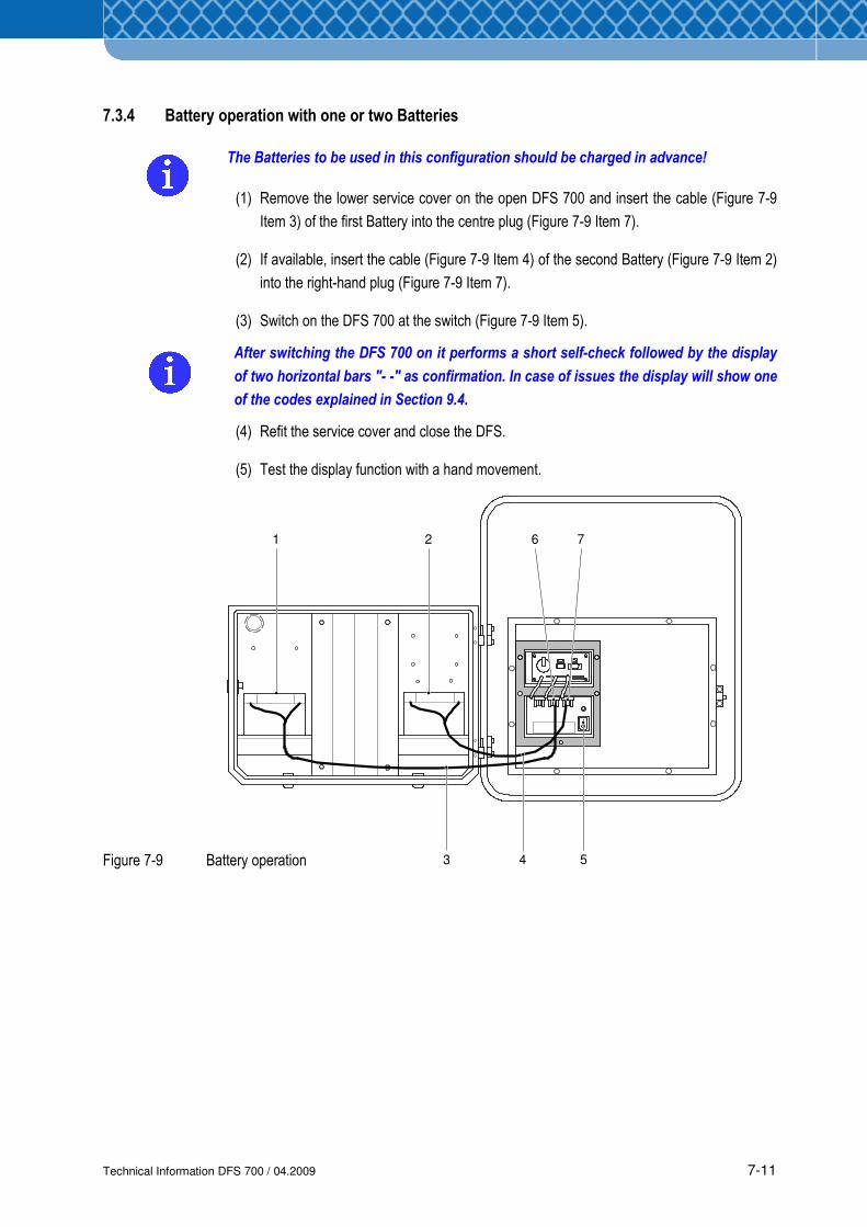
Technical Information DFS 700 / 04.2009 7-11
1 6 7
543
2
7.3.4 Battery operation with one or two Batteries
The Batteries to be used in this configuration should be charged in advance!
(1) Remove the lower service cover on the open DFS 700 and insert the cable (Figure 7-9
Item 3) of the first Battery into the centre plug (Figure 7-9 Item 7).
(2) If available, insert the cable (Figure 7-9 Item 4) of the second Battery (Figure 7-9 Item 2)
into the right-hand plug (Figure 7-9 Item 7).
(3) Switch on the DFS 700 at the switch (Figure 7-9 Item 5).
After switching the DFS 700 on it performs a short self-check followed by the display
of two horizontal bars "- -" as confirmation. In case of issues the display will show one
of the codes explained in Section 9.4.
(4) Refit the service cover and close the DFS.
(5) Test the display function with a hand movement.
Figure 7-9 Battery operation
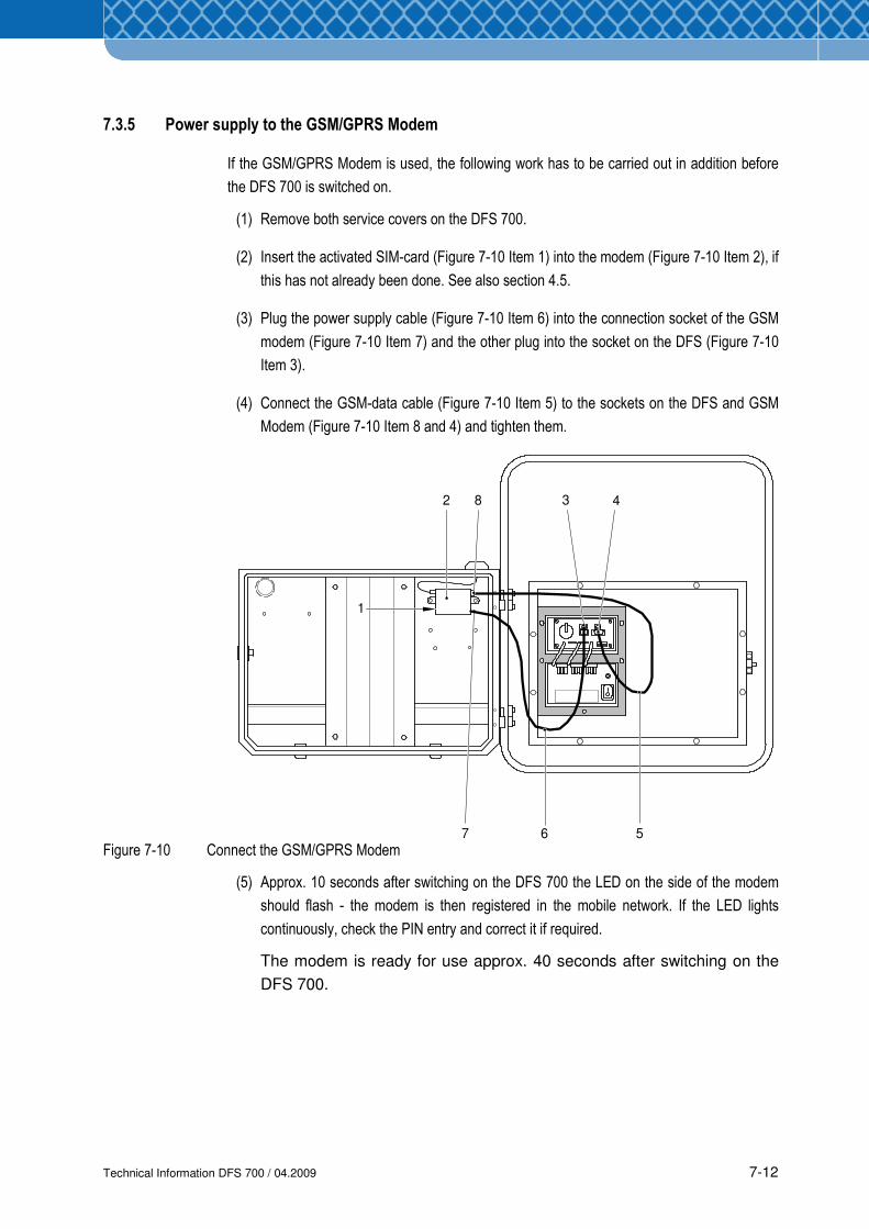
Technical Information DFS 700 / 04.2009 7-12
3 4
67
2
1
8
5
7.3.5 Power supply to the GSM/GPRS Modem
If the GSM/GPRS Modem is used, the following work has to be carried out in addition before
the DFS 700 is switched on.
(1) Remove both service covers on the DFS 700.
(2) Insert the activated SIM-card (Figure 7-10 Item 1) into the modem (Figure 7-10 Item 2), if
this has not already been done. See also section 4.5.
(3) Plug the power supply cable (Figure 7-10 Item 6) into the connection socket of the GSM
modem (Figure 7-10 Item 7) and the other plug into the socket on the DFS (Figure 7-10
Item 3).
(4) Connect the GSM-data cable (Figure 7-10 Item 5) to the sockets on the DFS and GSM
Modem (Figure 7-10 Item 8 and 4) and tighten them.
Figure 7-10 Connect the GSM/GPRS Modem
(5) Approx. 10 seconds after switching on the DFS 700 the LED on the side of the modem
should flash - the modem is then registered in the mobile network. If the LED lights
continuously, check the PIN entry and correct it if required.
The modem is ready for use approx. 40 seconds after switching on the
DFS 700.
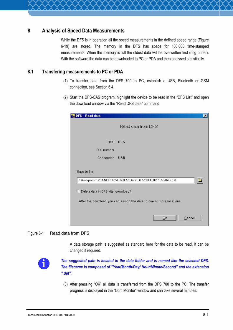
Technical Information DFS 700 / 04.2009 8-1
8 Analysis of Speed Data Measurements
While the DFS is in operation all the speed measurements in the defined speed range (Figure
6-19) are stored. The memory in the DFS has space for 100,000 time-stamped
measurements. When the memory is full the oldest data will be overwritten first (ring buffer).
With the software the data can be downloaded to PC or PDA and then analysed statistically.
8.1 Transfering measurements to PC or PDA
(1) To transfer data from the DFS 700 to PC, establish a USB, Bluetooth or GSM
connection, see Section 6.4.
(2) Start the DFS-CAS program, highlight the device to be read in the “DFS List” and open
the download window via the “Read DFS data” command.
Figure 8-1 Read data from DFS
A data storage path is suggested as standard here for the data to be read. It can be
changed if required.
The suggested path is located in the data folder and is named like the selected DFS.
The filename is composed of "Year/Month/Day/ Hour/Minute/Second" and the extension
".dat".
(3) After pressing “OK” all data is transferred from the DFS 700 to the PC. The transfer
progress is displayed in the "Com Monitor" window and can take several minutes.
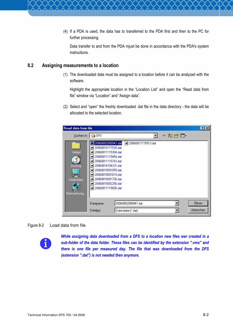
Technical Information DFS 700 / 04.2009 8-2
(4) If a PDA is used, the data has to transferred to the PDA first and then to the PC for
further processing.
Data transfer to and from the PDA mjust be done in accordance with the PDA's system
instructions.
8.2 Assigning measurements to a location
(1) The downloaded data must be assigned to a location before it can be analyzed with the
software.
Highlight the appropriate location in the “Location List” and open the “Read data from
file” window via “Location” and “Assign data”.
(2) Select and “open” the freshly downloaded .dat file in the data directory - the data will be
allocated to the selected location.
Figure 8-2 Load data from file
While assigning data downloaded from a DFS to a location new files wer created in a
sub-folder of the data folder. These files can be identified by the extension ".vms" and
there is one file per measured day. The file that was downloaded from the DFS
(extension ".dat") is not needed then anymore.
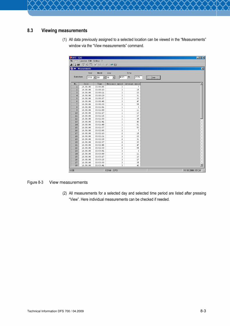
Technical Information DFS 700 / 04.2009 8-3
8.3 Viewing measurements
(1) All data previously assigned to a selected location can be viewed in the “Measurements”
window via the “View measurements” command.
Figure 8-3 View measurements
(2) All measurements for a selected day and selected time period are listed after pressing
“View”. Here individual measurements can be checked if needed.
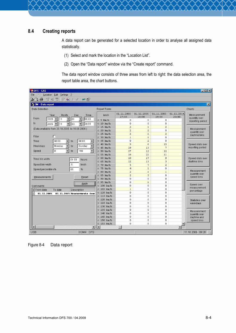
Technical Information DFS 700 / 04.2009 8-4
8.4 Creating reports
A data report can be generated for a selected location in order to analyse all assigned data
statistically.
(1) Select and mark the location in the “Location List”.
(2) Open the “Data report” window via the “Create report” command.
The data report window consists of three areas from left to right: the data selection area, the
report table area, the chart buttons.
Figure 8-4 Data report
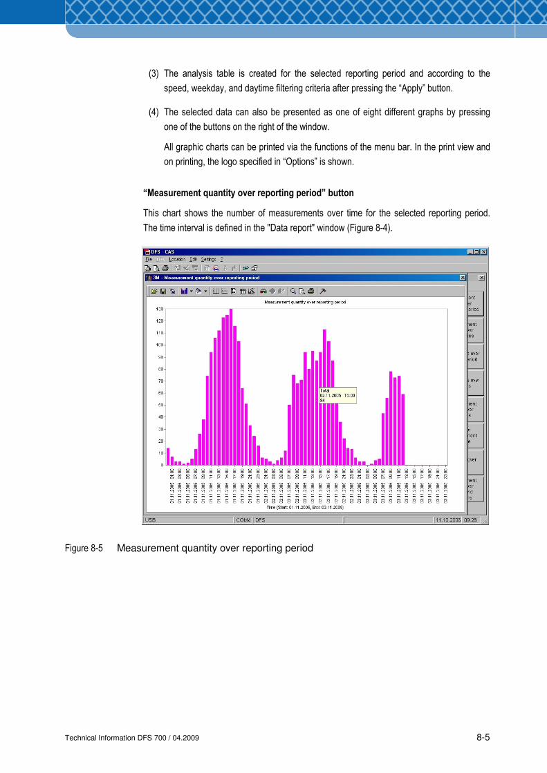
Technical Information DFS 700 / 04.2009 8-5
(3) The analysis table is created for the selected reporting period and according to the
speed, weekday, and daytime filtering criteria after pressing the “Apply” button.
(4) The selected data can also be presented as one of eight different graphs by pressing
one of the buttons on the right of the window.
All graphic charts can be printed via the functions of the menu bar. In the print view and
on printing, the logo specified in “Options” is shown.
“Measurement quantity over reporting period” button
This chart shows the number of measurements over time for the selected reporting period.
The time interval is defined in the "Data report" window (Figure 8-4).
Figure 8-5 Measurement quantity over reporting period
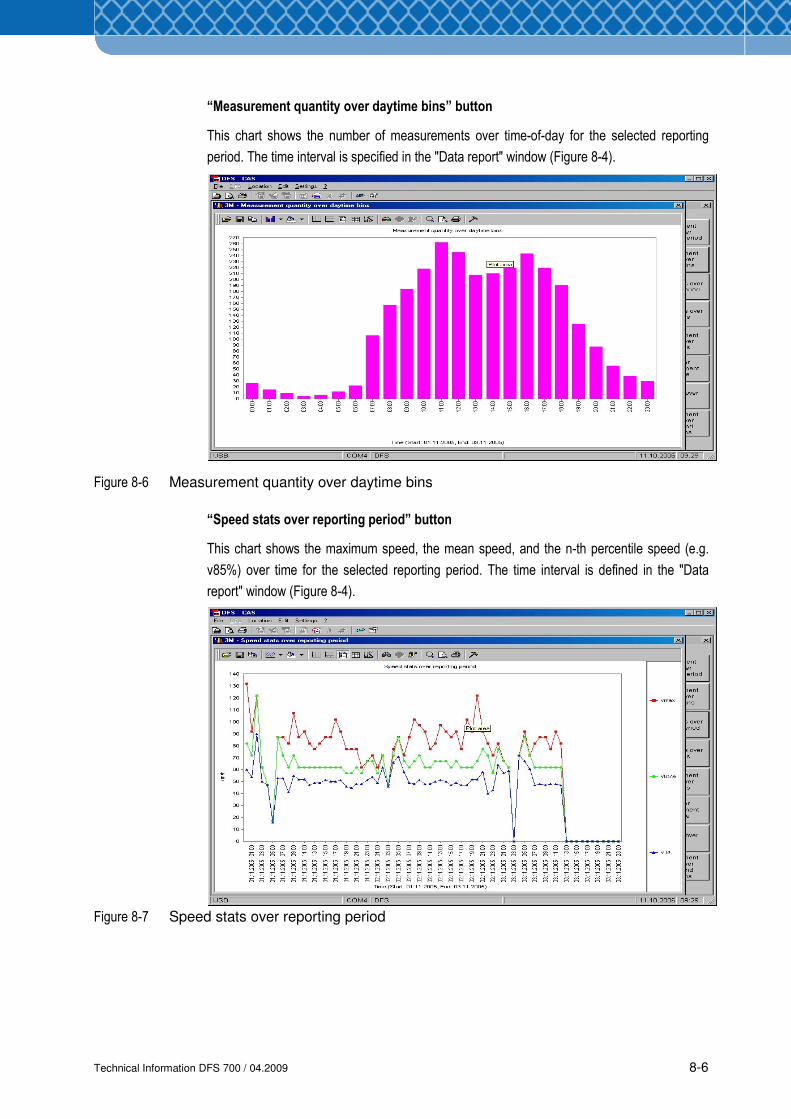
Technical Information DFS 700 / 04.2009 8-6
“Measurement quantity over daytime bins” button
This chart shows the number of measurements over time-of-day for the selected reporting
period. The time interval is specified in the "Data report" window (Figure 8-4).
Figure 8-6 Measurement quantity over daytime bins
“Speed stats over reporting period” button
This chart shows the maximum speed, the mean speed, and the n-th percentile speed (e.g.
v85%) over time for the selected reporting period. The time interval is defined in the "Data
report" window (Figure 8-4).
Figure 8-7 Speed stats over reporting period
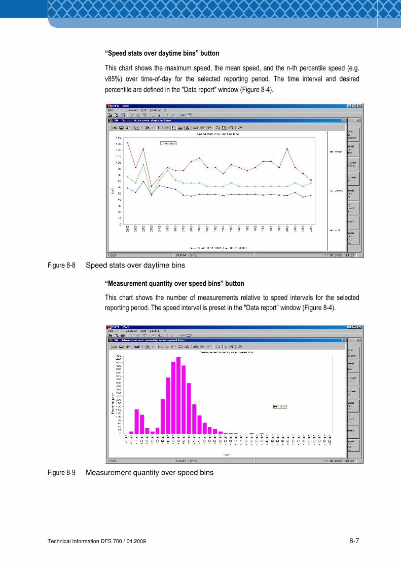
Technical Information DFS 700 / 04.2009 8-7
“Speed stats over daytime bins” button
This chart shows the maximum speed, the mean speed, and the n-th percentile speed (e.g.
v85%) over time-of-day for the selected reporting period. The time interval and desired
percentile are defined in the "Data report" window (Figure 8-4).
Figure 8-8 Speed stats over daytime bins
“Measurement quantity over speed bins” button
This chart shows the number of measurements relative to speed intervals for the selected
reporting period. The speed interval is preset in the "Data report" window (Figure 8-4).
Figure 8-9 Measurement quantity over speed bins
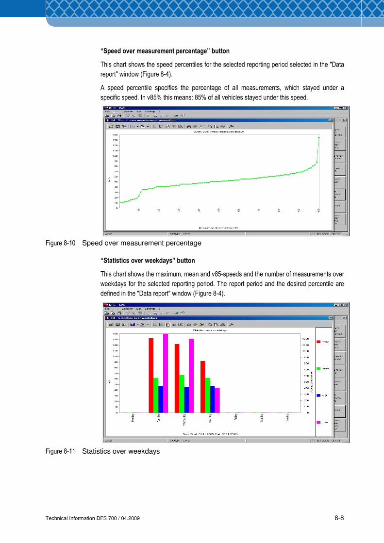
Technical Information DFS 700 / 04.2009 8-8
“Speed over measurement percentage” button
This chart shows the speed percentiles for the selected reporting period selected in the "Data
report" window (Figure 8-4).
A speed percentile specifies the percentage of all measurements, which stayed under a
specific speed. In v85% this means: 85% of all vehicles stayed under this speed.
Figure 8-10 Speed over measurement percentage
“Statistics over weekdays” button
This chart shows the maximum, mean and v85-speeds and the number of measurements over
weekdays for the selected reporting period. The report period and the desired percentile are
defined in the "Data report" window (Figure 8-4).
Figure 8-11 Statistics over weekdays
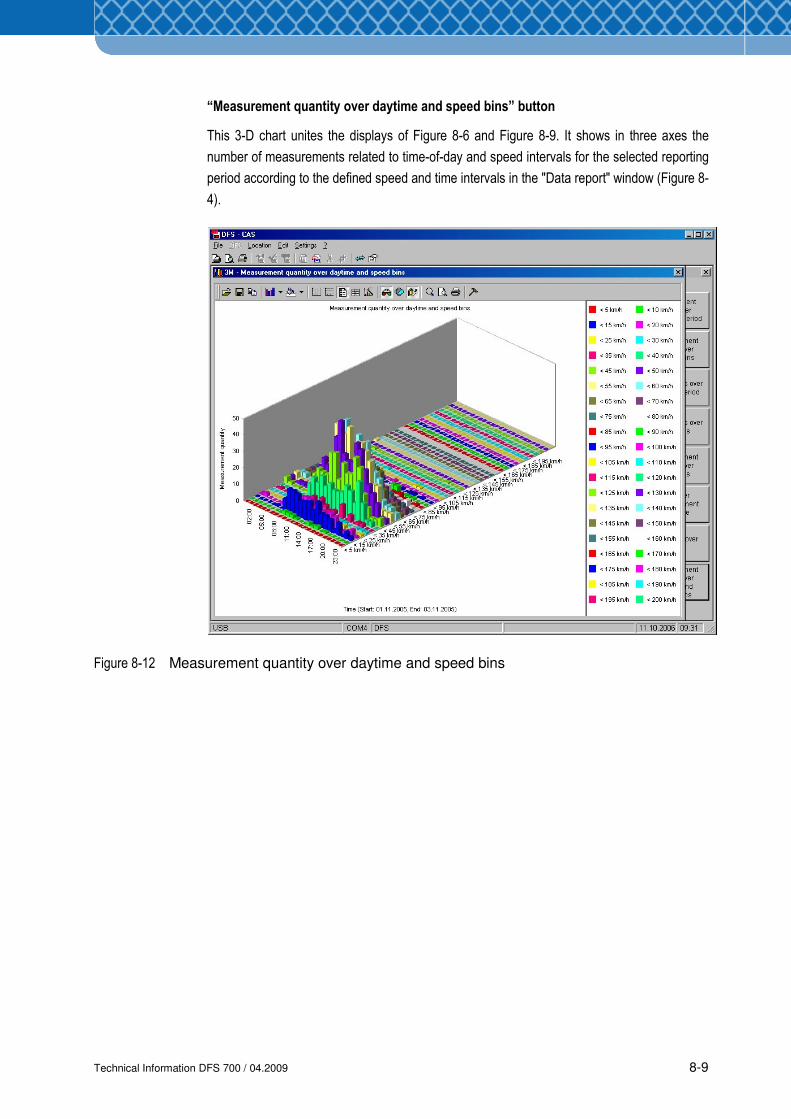
Technical Information DFS 700 / 04.2009 8-9
“Measurement quantity over daytime and speed bins” button
This 3-D chart unites the displays of Figure 8-6 and Figure 8-9. It shows in three axes the
number of measurements related to time-of-day and speed intervals for the selected reporting
period according to the defined speed and time intervals in the "Data report" window (Figure 8-
4).
Figure 8-12 Measurement quantity over daytime and speed bins

Technical Information DFS 700 / 04.2009 8-10
Technical Information DFS 700 / 04.2009 9-1
9 Service and Maintenance
9.1 Cleaning
(1) Clean the speed display and the reflective front of the frame with a clean, dry cloth
The use of aggressive detergents and abrasives can damage the reflective coating and
should therefore be avoided!
(2) Clean all air vents on the DFS 700 outside and inside with a cloth or a broom. The air
supply vents must always be kept uncovered.
(3) Clean rough dirt from the DFS 700 with a broom.
9.2 Maintenance
The DFS 700 is maintenance-free as a basic principle.
Before setting it up, subject the equipment to a visual inspection and, while doing so, pay
particular attention to the condition of the mains cables. These must not be damaged but, if
they are, have the cable replaced by a qualified electrician.
If Batteries are used, check that their external condition is perfect in advance. In case of
damage, replace the Battery.
When handling bateries pay particular attention to further safety advices as specified in
Section 2. Risk of injury as a result of leaking liquid exists!
When replacing components only original 3M parts should be used. The manufacturer’s
warranty expires if components from other manufaturers are used.
The electrical connection components such as plugs, sockets, cables, etc., are standard
commercial electrical goods which can be replaced by a qualified electrician.
NOTE
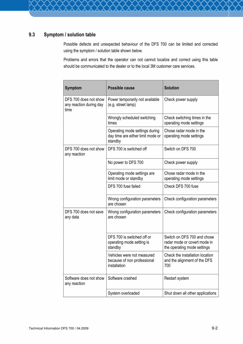
Technical Information DFS 700 / 04.2009 9-2
9.3 Symptom / solution table
Possible defects and unexpected behaviour of the DFS 700 can be limited and corrected
using the symptom / solution table shown below.
Problems and errors that the operator can not cannot localize and correct using this table
should be communicated to the dealer or to the local 3M customer care services.
Symptom Possible cause Solution
Power temporarily not available (e.g. street lamp)
Check power supply
Wrongly scheduled switching times
Check switching times in the operating mode settings
DFS 700 does not show any reaction during day time
Operating mode settings during day time are either limit mode or standby
Chose radar mode in the operating mode settings
DFS 700 is switched off Switch on DFS 700
No power to DFS 700 Check power supply
Operating mode settings are limit mode or standby
Chose radar mode in the operating mode settings
DFS 700 fuse failed Check DFS 700 fuse
DFS 700 does not show any reaction
Wrong configuration parameters are chosen
Check configuration parameters
Wrong configuration parameters are chosen
Check configuration parameters
DFS 700 is switched off or operating mode setting is standby
Switch on DFS 700 and chose radar mode or covert mode in the operating mode settings
DFS 700 does not save any data
Vehicles were not measured because of non professional installation
Check the installation location and the alignment of the DFS 700
Software crashed Restart system Software does not show any reaction
System overloaded Shut down all other applications
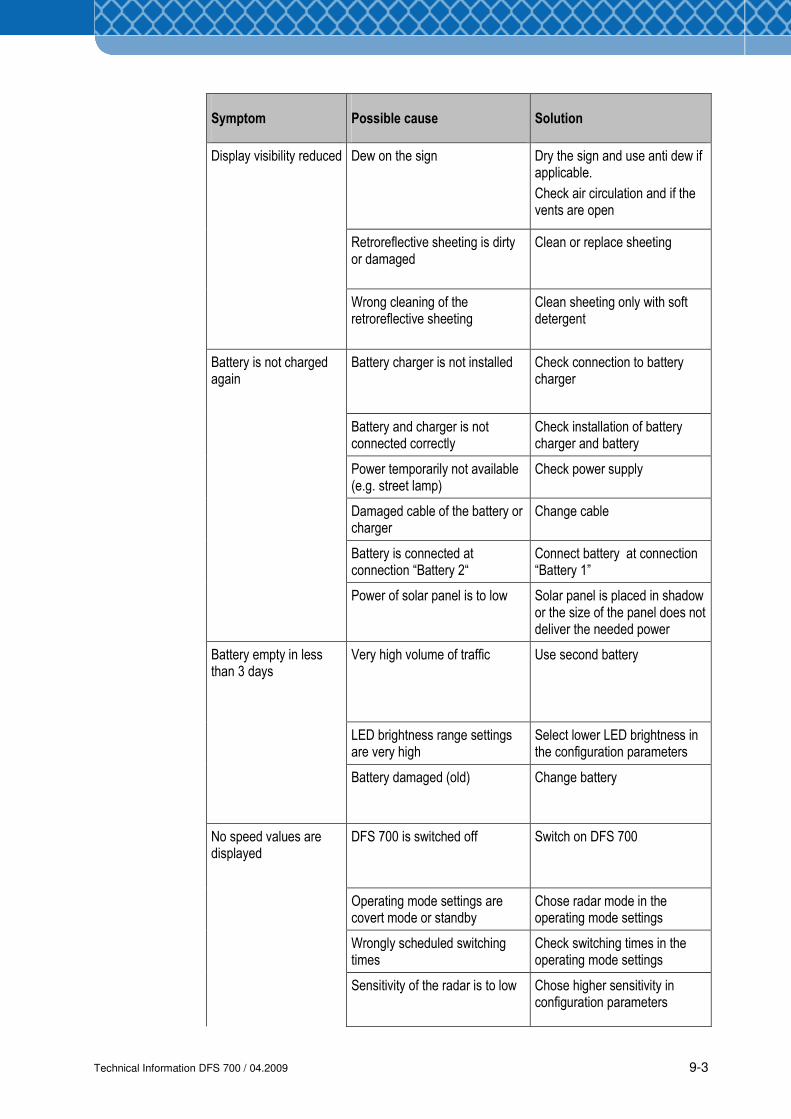
Technical Information DFS 700 / 04.2009 9-3
Symptom Possible cause Solution
Dew on the sign
Dry the sign and use anti dew if applicable.
Check air circulation and if the vents are open
Retroreflective sheeting is dirty or damaged
Clean or replace sheeting
Display visibility reduced
Wrong cleaning of the retroreflective sheeting
Clean sheeting only with soft detergent
Battery charger is not installed Check connection to battery charger
Battery and charger is not connected correctly
Check installation of battery charger and battery
Power temporarily not available (e.g. street lamp)
Check power supply
Damaged cable of the battery or charger
Change cable
Battery is connected at connection “Battery 2“
Connect battery at connection “Battery 1”
Battery is not charged again
Power of solar panel is to low Solar panel is placed in shadow or the size of the panel does not deliver the needed power
Very high volume of traffic Use second battery
LED brightness range settings are very high
Select lower LED brightness in the configuration parameters
Battery empty in less than 3 days
Battery damaged (old) Change battery
DFS 700 is switched off Switch on DFS 700
Operating mode settings are covert mode or standby
Chose radar mode in the operating mode settings
Wrongly scheduled switching times
Check switching times in the operating mode settings
No speed values are displayed
Sensitivity of the radar is to low Chose higher sensitivity in configuration parameters
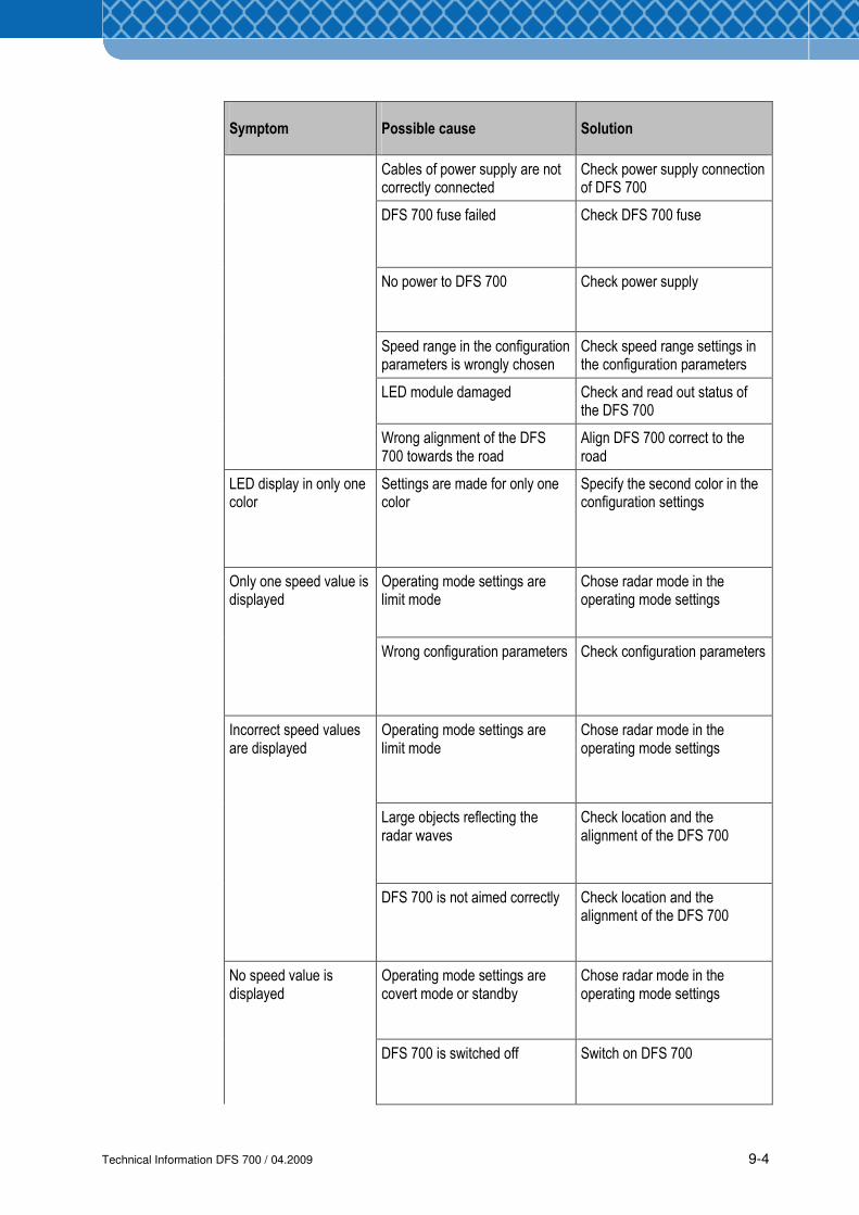
Technical Information DFS 700 / 04.2009 9-4
Symptom Possible cause Solution
Cables of power supply are not correctly connected
Check power supply connection of DFS 700
DFS 700 fuse failed Check DFS 700 fuse
No power to DFS 700 Check power supply
Speed range in the configuration parameters is wrongly chosen
Check speed range settings in the configuration parameters
LED module damaged Check and read out status of the DFS 700
Wrong alignment of the DFS 700 towards the road
Align DFS 700 correct to the road
LED display in only one color
Settings are made for only one color
Specify the second color in the configuration settings
Operating mode settings are limit mode
Chose radar mode in the operating mode settings
Only one speed value is displayed
Wrong configuration parameters Check configuration parameters
Operating mode settings are limit mode
Chose radar mode in the operating mode settings
Large objects reflecting the radar waves
Check location and the alignment of the DFS 700
Incorrect speed values are displayed
DFS 700 is not aimed correctly Check location and the alignment of the DFS 700
Operating mode settings are covert mode or standby
Chose radar mode in the operating mode settings
No speed value is displayed
DFS 700 is switched off Switch on DFS 700
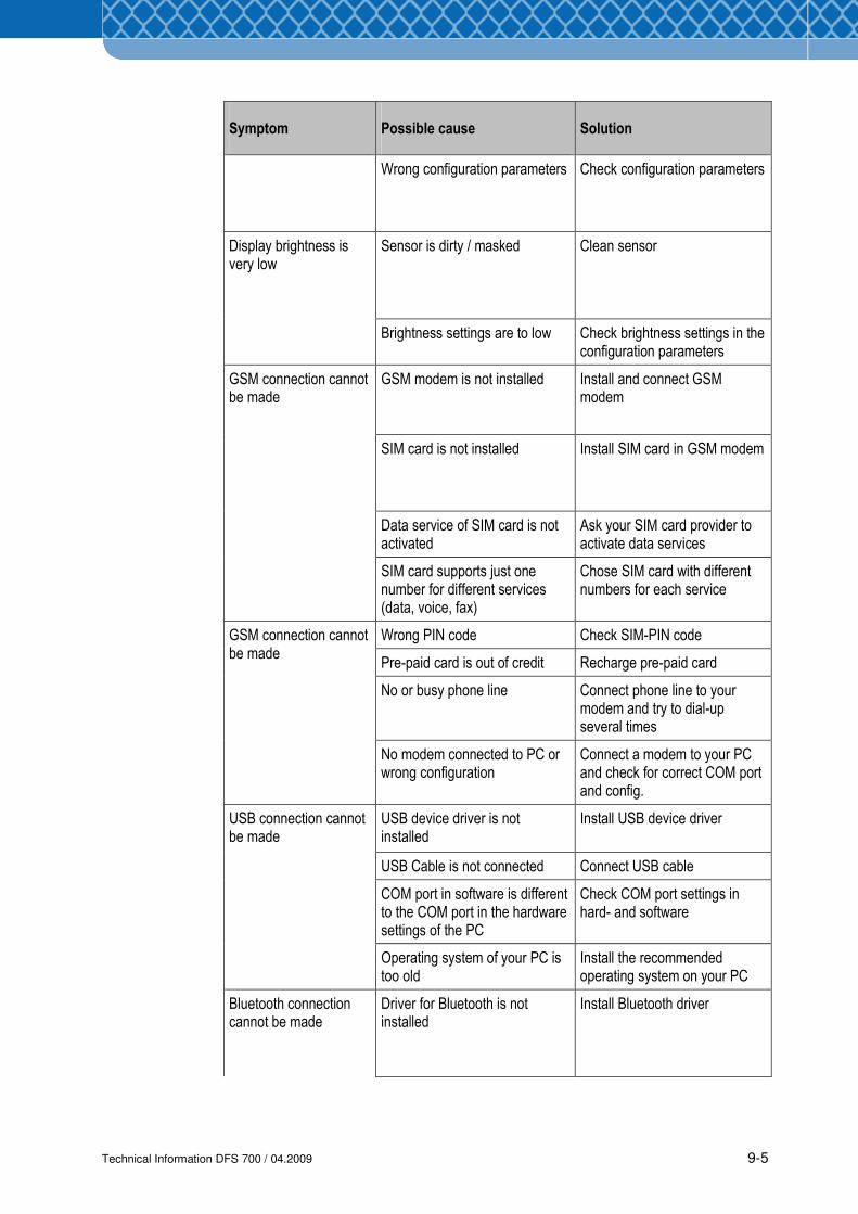
Technical Information DFS 700 / 04.2009 9-5
Symptom Possible cause Solution
Wrong configuration parameters Check configuration parameters
Sensor is dirty / masked Clean sensor Display brightness is very low
Brightness settings are to low Check brightness settings in the configuration parameters
GSM modem is not installed Install and connect GSM modem
SIM card is not installed Install SIM card in GSM modem
Data service of SIM card is not activated
Ask your SIM card provider to activate data services
GSM connection cannot be made
SIM card supports just one number for different services (data, voice, fax)
Chose SIM card with different numbers for each service
Wrong PIN code Check SIM-PIN code
Pre-paid card is out of credit Recharge pre-paid card
No or busy phone line Connect phone line to your modem and try to dial-up several times
GSM connection cannot be made
No modem connected to PC or wrong configuration
Connect a modem to your PC and check for correct COM port and config.
USB device driver is not installed
Install USB device driver
USB Cable is not connected Connect USB cable
COM port in software is different to the COM port in the hardware settings of the PC
Check COM port settings in hard- and software
USB connection cannot be made
Operating system of your PC is too old
Install the recommended operating system on your PC
Bluetooth connection cannot be made
Driver for Bluetooth is not installed
Install Bluetooth driver
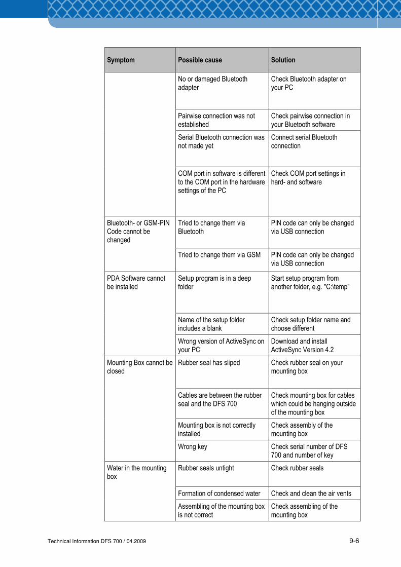
Technical Information DFS 700 / 04.2009 9-6
Symptom Possible cause Solution
No or damaged Bluetooth adapter
Check Bluetooth adapter on your PC
Pairwise connection was not established
Check pairwise connection in your Bluetooth software
Serial Bluetooth connection was not made yet
Connect serial Bluetooth connection
COM port in software is different to the COM port in the hardware settings of the PC
Check COM port settings in hard- and software
Tried to change them via Bluetooth
PIN code can only be changed via USB connection
Bluetooth- or GSM-PIN Code cannot be changed
Tried to change them via GSM
PIN code can only be changed via USB connection
Setup program is in a deep folder
Start setup program from another folder, e.g. "C:\temp"
Name of the setup folder includes a blank
Check setup folder name and choose different
PDA Software cannot be installed
Wrong version of ActiveSync on your PC
Download and install ActiveSync Version 4.2
Rubber seal has sliped Check rubber seal on your mounting box
Cables are between the rubber seal and the DFS 700
Check mounting box for cables which could be hanging outside of the mounting box
Mounting box is not correctly installed
Check assembly of the mounting box
Mounting Box cannot be closed
Wrong key Check serial number of DFS 700 and number of key
Rubber seals untight Check rubber seals
Formation of condensed water Check and clean the air vents
Water in the mounting box
Assembling of the mounting box is not correct
Check assembling of the mounting box

Technical Information DFS 700 / 04.2009 9-7
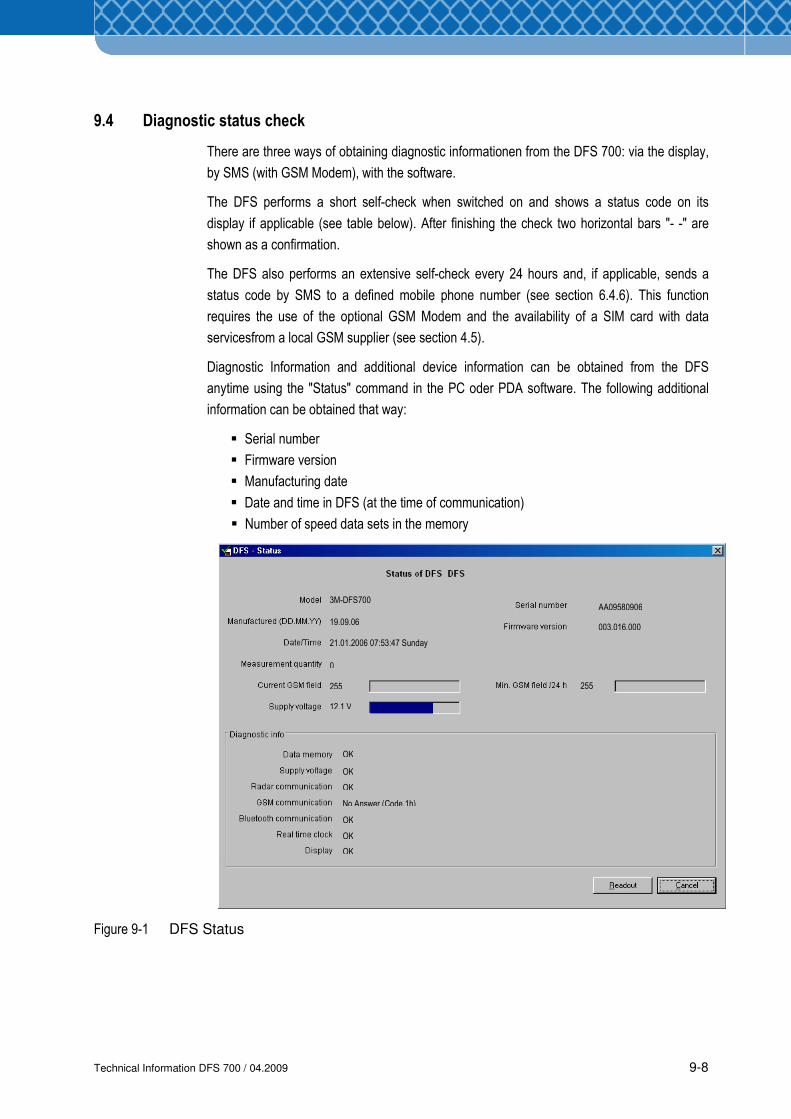
Technical Information DFS 700 / 04.2009 9-8
9.4 Diagnostic status check
There are three ways of obtaining diagnostic informationen from the DFS 700: via the display,
by SMS (with GSM Modem), with the software.
The DFS performs a short self-check when switched on and shows a status code on its
display if applicable (see table below). After finishing the check two horizontal bars "- -" are
shown as a confirmation.
The DFS also performs an extensive self-check every 24 hours and, if applicable, sends a
status code by SMS to a defined mobile phone number (see section 6.4.6). This function
requires the use of the optional GSM Modem and the availability of a SIM card with data
servicesfrom a local GSM supplier (see section 4.5).
Diagnostic Information and additional device information can be obtained from the DFS
anytime using the "Status" command in the PC oder PDA software. The following additional
information can be obtained that way:
� Serial number
� Firmware version
� Manufacturing date
� Date and time in DFS (at the time of communication)
� Number of speed data sets in the memory
Figure 9-1 DFS Status
3M-DFS700
19.09.06
21.01.2006 07:53:47 Sunday
0
255
12,1 V
OK
OK
OK
No Answer (Code 1h)
AA09580906
OK
OK
OK
003.016.000
255
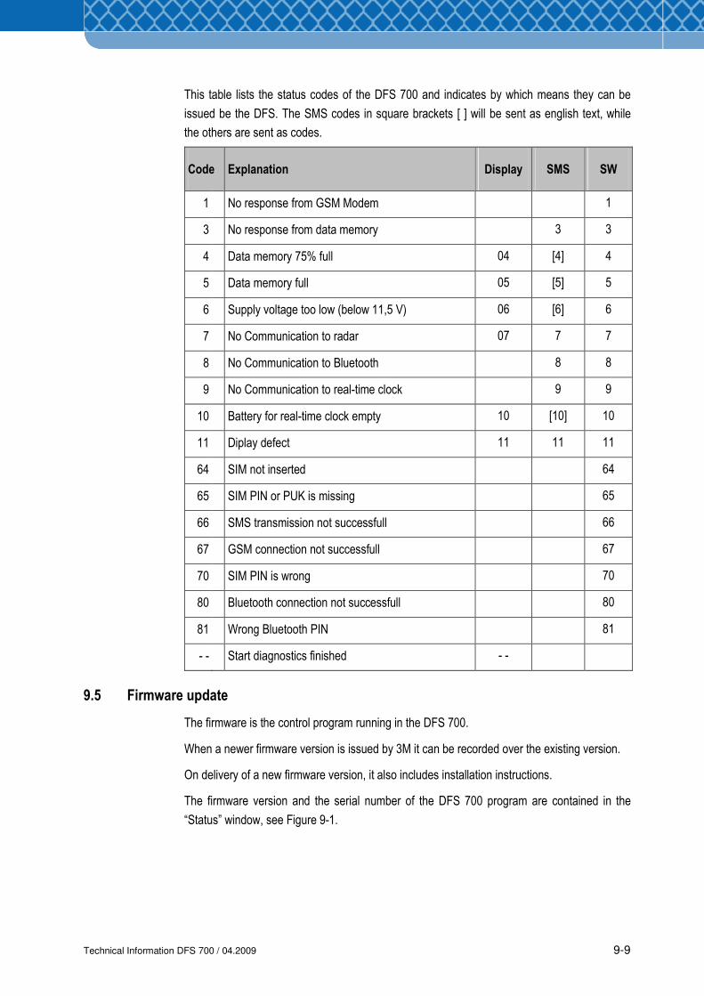
Technical Information DFS 700 / 04.2009 9-9
This table lists the status codes of the DFS 700 and indicates by which means they can be
issued be the DFS. The SMS codes in square brackets [ ] will be sent as english text, while
the others are sent as codes.
Code Explanation Display SMS SW
1 No response from GSM Modem 1
3 No response from data memory 3 3
4 Data memory 75% full 04 [4] 4
5 Data memory full 05 [5] 5
6 Supply voltage too low (below 11,5 V) 06 [6] 6
7 No Communication to radar 07 7 7
8 No Communication to Bluetooth 8 8
9 No Communication to real-time clock 9 9
10 Battery for real-time clock empty 10 [10] 10
11 Diplay defect 11 11 11
64 SIM not inserted 64
65 SIM PIN or PUK is missing 65
66 SMS transmission not successfull 66
67 GSM connection not successfull 67
70 SIM PIN is wrong 70
80 Bluetooth connection not successfull 80
81 Wrong Bluetooth PIN 81
- - Start diagnostics finished - -
9.5 Firmware update
The firmware is the control program running in the DFS 700.
When a newer firmware version is issued by 3M it can be recorded over the existing version.
On delivery of a new firmware version, it also includes installation instructions.
The firmware version and the serial number of the DFS 700 program are contained in the
“Status” window, see Figure 9-1.
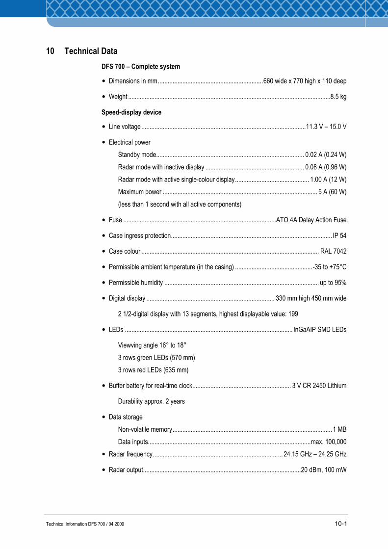
Technical Information DFS 700 / 04.2009 10-1
10 Technical Data
DFS 700 – Complete system
• Dimensions in mm................................................................660 wide x 770 high x 110 deep
• Weight ...........................................................................................................................8.5 kg
Speed-display device
• Line voltage....................................................................................................11.3 V – 15.0 V
• Electrical power
Standby mode.......................................................................................... 0.02 A (0.24 W)
Radar mode with inactive display ............................................................ 0.08 A (0.96 W)
Radar mode with active single-colour display............................................. 1.00 A (12 W)
Maximum power .............................................................................................. 5 A (60 W)
(less than 1 second with all active components)
• Fuse .............................................................................................ATO 4A Delay Action Fuse
• Case ingress protection.................................................................................................. IP 54
• Case colour ............................................................................................................ RAL 7042
• Permissible ambient temperature (in the casing) ...............................................-35 to +75°C
• Permissible humidity .............................................................................................. up to 95%
• Digital display .............................................................................. 330 mm high 450 mm wide
2 1/2-digital display with 13 segments, highest displayable value: 199
• LEDs ...................................................................................................... InGaAIP SMD LEDs
Viewving angle 16° to 18°
3 rows green LEDs (570 mm)
3 rows red LEDs (635 mm)
• Buffer battery for real-time clock............................................................ 3 V CR 2450 Lithium
Durability approx. 2 years
• Data storage
Non-volatile memory.................................................................................................1 MB
Data inputs...................................................................................................max. 100,000
• Radar frequency............................................................................... 24.15 GHz – 24.25 GHz
• Radar output................................................................................................20 dBm, 100 mW
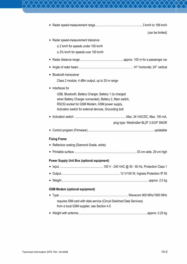
Technical Information DFS 700 / 04.2009 10-2
• Radar speed-measurement range............................................................3 km/h to 199 km/h
(can be limited)
• Radar speed-measurement tolerance
± 2 km/h for speeds under 100 km/h
± 2% km/h for speeds over 100 km/h
• Radar distance range .......................................................approx. 100 m for a passenger car
• Angle of radar beam..................................................................... 14° horizontal, 24° vertical
• Bluetooth transceiver
Class 2 module, 4 dBm output, up to 20 m range
• Interfaces for
USB, Bluetooth, Battery Charger, Battery 1 (is charged
when Battery Charger connected), Battery 2, Main switch,
RS232-socket for GSM Modem, GSM power supply,
Activation switch for external devices, Grounding bolt
• Activation switch .................................................................Max. 24 VAC/DC, Max. 150 mA,
plug type: Weidmüller BLZF 3.5/3/F SNOR
• Control program (Firmware) ....................................................................................updatable
Fixing Frame
• Reflective coating (Diamond Grade, white)
• Printable surface ...............................................................................53 cm wide, 29 cm high
Power Supply Unit Box (optional equipment)
• Input ....................................................... 100 V - 240 VAC @ 50 - 60 Hz, Protection Class 1
• Output.......................................................................... 12 V/100 W, Ingress Protection IP 55
• Weight ..............................................................................................................approx. 2.0 kg
GSM Modem (optional equipment)
• Type .......................................................................................Wavecom 900 MHz/1800 MHz
requires SIM-card with data service (Circuit Switched Data Services)
from a local GSM supplier, see Section 4.5
• Weight with antenna.......................................................................................approx. 0.25 kg
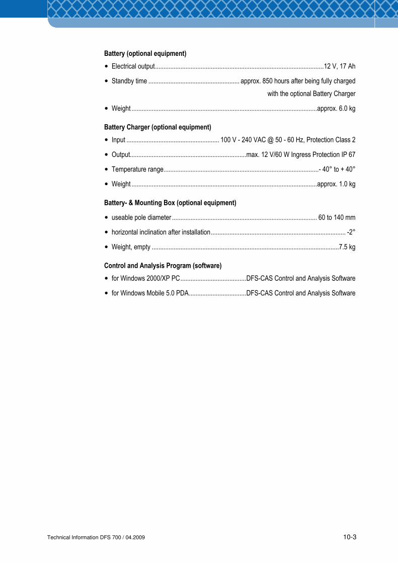
Technical Information DFS 700 / 04.2009 10-3
Battery (optional equipment)
• Electrical output....................................................................................................12 V, 17 Ah
• Standby time ...................................................... approx. 850 hours after being fully charged
with the optional Battery Charger
• Weight ..............................................................................................................approx. 6.0 kg
Battery Charger (optional equipment)
• Input ....................................................... 100 V - 240 VAC @ 50 - 60 Hz, Protection Class 2
• Output.....................................................................max. 12 V/60 W Ingress Protection IP 67
• Temperature range............................................................................................- 40° to + 40°
• Weight ..............................................................................................................approx. 1.0 kg
Battery- & Mounting Box (optional equipment)
• useable pole diameter ...................................................................................... 60 to 140 mm
• horizontal inclination after installation................................................................................ -2°
• Weight, empty ...............................................................................................................7.5 kg
Control and Analysis Program (software)
• for Windows 2000/XP PC.......................................DFS-CAS Control and Analysis Software
• for Windows Mobile 5.0 PDA..................................DFS-CAS Control and Analysis Software

Technical Information DFS 700 / 04.2009 10-4