3M Scotchcast Mine and Portable Cable Splice and Jacket ... · 1 of 22 3M™ Scotchcast ™ Mine...
22
1 of 22 3M ™ Scotchcast ™ Mine and Portable Cable Splice and Jacket Repair Kit M-20 Instructions 1 & 2 For Jacket Repair (pages 2 & 6) Supplemental Instructions for: • Insulation Repair (page 10) • Conductor Repair (page 13) • Cable Splice (page 16) • Cable Crotch Seal (page 19) Kit Contents: • Funnels • Wrap-around Splice Mold • Rubber Mold Straps • Funnel Supports • 3M™ Cable Repair Spacer Web NOTE: 3M™ SCOTCHCAST™ FLAME-RETARDANT COMPOUND 2131 IS REQUIRED FOR ALL REPAIRS, BUT IS NOT INCLUDED IN KIT. ADDITIONAL MATERIALS REQUIRED FOR SUPPLEMENTAL REPAIRS AS LISTED IN APPLICABLE INSTRUCTION. DANGER: BEFORE ATTEMPTING ANY CABLE REPAIRS, MAKE SURE THAT THE PROPER CABLE IS DISCONNECTED, LOCKED OUT AND SUITABLY TAGGED. Technical Information : Cable Diameter Range: 1.60 to 2.5 in. Mine Safety and Health Administration Acceptance: 07-KA060007-MSHA August, 2011 78-8126-9790-8 A
Transcript of 3M Scotchcast Mine and Portable Cable Splice and Jacket ... · 1 of 22 3M™ Scotchcast ™ Mine...

1 of 22
3M™ Scotchcast™ Mine and Portable Cable Splice and Jacket Repair Kit M-20
Instructions 1 & 2 For Jacket Repair (pages 2 & 6) Supplemental Instructions for:
• Insulation Repair (page 10) • Conductor Repair (page 13) • Cable Splice (page 16) • Cable Crotch Seal (page 19) Kit Contents:
• Funnels • Wrap-around Splice Mold • Rubber Mold Straps • Funnel Supports • 3M™ Cable Repair Spacer Web
NOTE: 3M™ SCOTCHCAST™ FLAME-RETARDANT COMPOUND 2131 IS REQUIRED FOR ALL REPAIRS, BUT IS NOT INCLUDED IN KIT.
ADDITIONAL MATERIALS REQUIRED FOR SUPPLEMENTAL REPAIRS AS LISTED IN APPLICABLE INSTRUCTION.
DANGER: BEFORE ATTEMPTING ANY CABLE REPAIRS, MAKE SURE THAT THE PROPER CABLE IS DISCONNECTED, LOCKED OUT AND SUITABLY TAGGED.
Technical Information: Cable Diameter Range: 1.60 to 2.5 in. Mine Safety and Health Administration Acceptance: 07-KA060007-MSHA August, 2011 78-8126-9790-8 A

2 of 22
Instruction 1 - Jacket Repair Specifications:
• SHD-GC Cable • Other cable with jacket thickness of 3/16” or 0.19” (5 mm) or more • Generally cables considered as thick jacketed, with jacket thickness of 3/16” (5 mm) or more.
NOTE: If cable jacket thickness is less than 3/16” (5 mm), use Instruction 2 on page 6.
A. Prepare Cables
1. Position cable to eliminate bending or sagging of repair area. 2. Remove entire cable jacket from repair area, for a length not exceeding 13” (330 mm). (Figure 2) 3. FULLY taper jacket ends for 2” (50 mm). (Figure 2) 4. THOROUGHLY scuff jacket ends for 2” (50 mm) beyond taper. Clean dust from scuffed area. (Figure 2) 5. Overwrap ground conductors with 1 half-lapped layer of tape: - SHIELDED CABLE (SHD-GC), use Scotch® Electrical Semi-conducting Tape 13 - NON-SHIELDED CABLE (600/2000 V), use vinyl tape 6. Bind conductors together with band(s) of INVERTED vinyl tape (adhesive side out), located per spacer web positions shown in
Figure 3. (Figures 2 & 3)
78-8126-9790-8 A

3 of 22
B. Install 3M™ Cable Repair Spacer Web APPLIES ONLY TO REPAIR OPENINGS OF 6” (150 mm) AND LONGER 1. Wrap on 3M™ Spacer Web to form collar(s) per Figure 3; build up to diameter of cable jacket and cut off. (Figure 3) 2. Split end(s) of 3M™ Spacer Web and press into sides of collar(s). (Figure 4)
C. Install Mold
1. Inspect Mold: On previously used mold, make certain vent slits are clear of compound. 2. With cable straight, center mold over repair area with vent slits on top (printing on mold should be readable). Wrap snugly
around, tucking one edge under. (Figure 5)
NOTE: TUCKED EDGE MUST BE STRAIGHT TO FORM A SEAL.
78-8126-9790-8 A
4 of 22
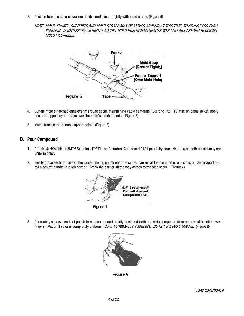
3. Position funnel supports over mold holes and secure tightly with mold straps. (Figure 6)
NOTE: MOLD, FUNNEL, SUPPORTS AND MOLD STRAPS MAY BE MOVED AROUND AT THIS TIME, TO ADJUST FOR FINAL POSITION. IF NECESSARY, SLIGHTLY ADJUST MOLD POSITION SO SPACER WEB COLLARS ARE NOT BLOCKING MOLD FILL-HOLES.
4. Bundle mold’s notched ends evenly around cable, maintaining cable centering. Starting 1/2” (12 mm) on cable jacket, apply one half-lapped layer of tape over the mold’s notched ends. (Figure 6)
5. Install funnels into funnel support holes. (Figure 6)
D. Pour Compound 1. Premix BLACK side of 3M™ Scotchcast™ Flame-Retardant Compound 2131 pouch by squeezing to a smooth consistency and
uniform color. 2. Firmly grasp each flat side of the closed mixing pouch near the center barrier; at the same time, pull sides of barrier apart and
roll sides of thumbs through barrier. Break the barrier all the way across to the side seals. (Figure 7) 3. Alternately squeeze ends of pouch forcing compound rapidly back and forth and strip compound from corners of pouch between
fingers. Mix until color is completely uniform – 30 to 40 VIGOROUS SQUEEZES. DO NOT EXCEED 1 MINUTE. (Figure 8)
78-8126-9790-8 A

5 of 22
4. Clip off a corner of pouch and immediately pour into funnels, alternating back and forth between them. 5. Fill mold until compound fills funnels to half full. 6. Allow compound to cure. 7. Check compound in funnels for curing.
NOTE: REPAIR MAY BE DE-MOLDED WHEN COMPOUND IS NO LONGER TACKY. Typical Cure Time: 16 – 24 hrs. @ 70ºF (21ºC) 24 – 30 hrs. @ 50ºF (10ºC) 36 hrs. @ 32ºF (0ºC) Typical De-mold Time: 1.5 hrs. @ 70ºF (21ºC) 4 hrs. @ 50ºF (10ºC) 6 – 8 hrs. @ 32ºF (0ºC)
NOTE: VALUES ARE TYPICAL, NOT TO BE CONSIDERED MINIMUM OR MAXIMUM. ALWAYS CONFIRM BASED ON TACK AND HARDNESS OF COMPOUND.
E. De-mold 1. Remove funnels by twisting and lifting, breaking off from compound. (Figure 9) 2. Remove mold straps and funnel supports. (Figure 9) 3. Carefully cut off any spout compound protrusions from repair, using a knife. (Figure 9)
4. Remove tape from mold ends.
5. Remove mold from cable repair, working from ends toward center.
78-8126-9790-8 A
6 of 22
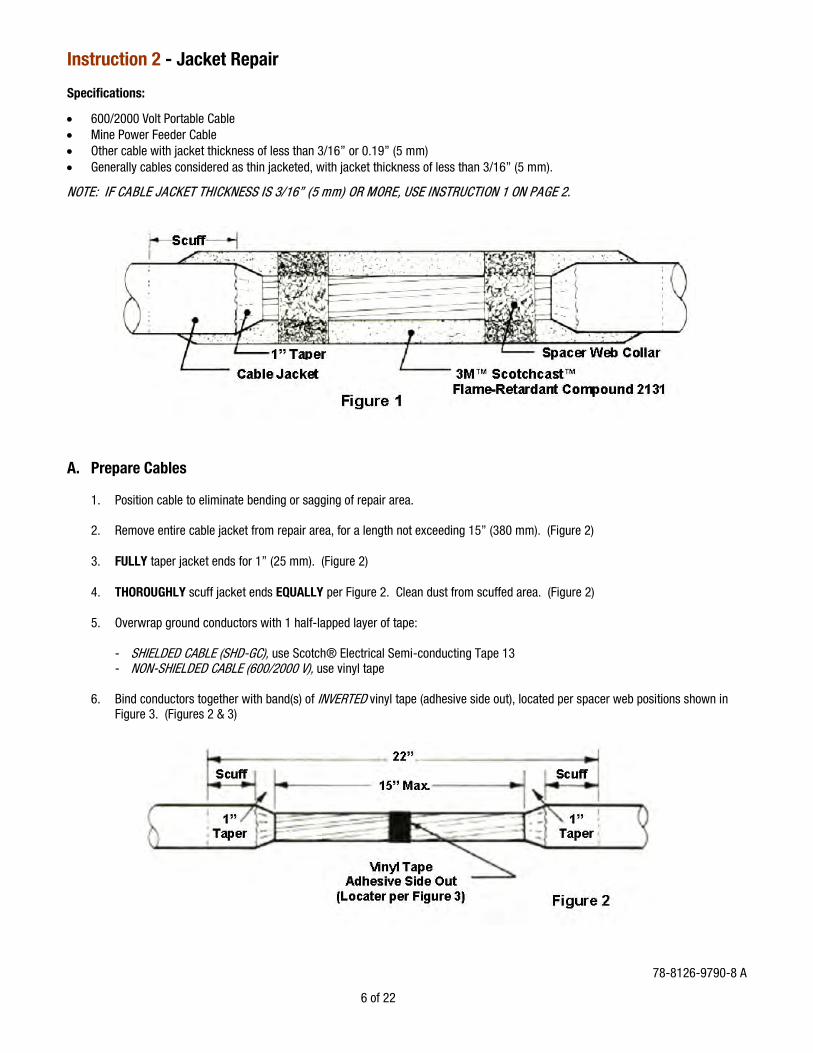
Instruction 2 - Jacket Repair Specifications:
• 600/2000 Volt Portable Cable • Mine Power Feeder Cable • Other cable with jacket thickness of less than 3/16” or 0.19” (5 mm) • Generally cables considered as thin jacketed, with jacket thickness of less than 3/16” (5 mm).
NOTE: IF CABLE JACKET THICKNESS IS 3/16” (5 mm) OR MORE, USE INSTRUCTION 1 ON PAGE 2. A. Prepare Cables 1. Position cable to eliminate bending or sagging of repair area. 2. Remove entire cable jacket from repair area, for a length not exceeding 15” (380 mm). (Figure 2) 3. FULLY taper jacket ends for 1” (25 mm). (Figure 2) 4. THOROUGHLY scuff jacket ends EQUALLY per Figure 2. Clean dust from scuffed area. (Figure 2) 5. Overwrap ground conductors with 1 half-lapped layer of tape: - SHIELDED CABLE (SHD-GC), use Scotch® Electrical Semi-conducting Tape 13 - NON-SHIELDED CABLE (600/2000 V), use vinyl tape 6. Bind conductors together with band(s) of INVERTED vinyl tape (adhesive side out), located per spacer web positions shown in
Figure 3. (Figures 2 & 3)
78-8126-9790-8 A

7 of 22
B. Install 3M™ Cable Repair Spacer Web 1. Wrap on 3M™ Spacer Web to form collar(s) per Figure 3; build up to diameter of cable jacket and cut off. (Figure 3) 2. Split end(s) of 3M™ Spacer Web and press into sides of collar(s). (Figure 4) C. Install Mold
1. Inspect Mold: On previously used mold, make certain vent slits are clear of compound. 2. With cable straight, center mold over repair area with vent slits on top (printing on mold should be readable). Wrap snugly
around, tucking one edge under. (Figure 5)
NOTE: TUCKED EDGE MUST BE STRAIGHT TO FORM A SEAL. 78-8126-9790-8 A

8 of 22
3. Position funnel supports over mold holes and secure tightly with mold straps. (Figure 6)
NOTE: MOLD, FUNNEL, SUPPORTS AND MOLD STRAPS MAY BE MOVED AROUND AT THIS TIME, TO ADJUST FOR FINAL POSITION. IF NECESSARY, SLIGHTLY ADJUST MOLD POSITION SO SPACER WEB COLLARS ARE NOT BLOCKING MOLD FILL-HOLES.
4. Bundle mold’s notched ends evenly around cable, maintaining cable centering. Starting 1/2” (12 mm) on cable jacket, apply one half-lapped layer of tape over the mold’s notched ends. (Figures 6 & 7)
NOTE: TENSION TAPE ONLY ENOUGH TO CONFORM TO MOLD. 5. Install funnels into funnel support holes. (Figure 6) D. Pour Compound 1. Premix BLACK side of 3M™ Scotchcast™ Flame-Retardant Compound 2131 pouch by squeezing to a smooth consistency and
uniform color. 2. Firmly grasp each flat side of the closed mixing pouch near the center barrier; at the same time, pull sides of barrier apart and
roll sides of thumbs through barrier. Break the barrier all the way across to the side seals. (Figure 8)
78-8126-9790-8 A

9 of 22
3. Alternately squeeze ends of pouch forcing compound rapidly back and forth and strip compound from corners of pouch between fingers. Mix until color is completely uniform – 30 to 40 VIGOROUS SQUEEZES. DO NOT EXCEED 1 MINUTE. (Figure 9)
4. Clip off a corner of pouch and immediately pour into funnels, alternating back and forth between them. 5. Fill mold until compound fills funnels to half full. 6. Allow compound to cure. 7. Check compound in funnels for curing.
NOTE: REPAIR MAY BE DE-MOLDED WHEN COMPOUND IS NO LONGER TACKY. Typical Cure Time: 16 – 24 hrs. @ 70ºF (21ºC) 24 – 30 hrs. @ 50ºF (10ºC) 36 hrs. @ 32ºF (0ºC)
Typical De-mold Time: 1.5 hrs. @ 70ºF (21ºC) 4 hrs. @ 50ºF (10ºC) 6 – 8 hrs. @ 32ºF (0ºC)
NOTE: VALUES ARE TYPICAL, NOT TO BE CONSIDERED MINIMUM OR MAXIMUM. ALWAYS CONFIRM BASED ON TACK AND HARDNESS OF COMPOUND.
E. De-mold 1. Remove funnels by twisting and lifting, breaking off from compound. (Figure 10) 2. Remove mold straps and funnel supports. (Figure 10) 3. Carefully cut off any spout compound protrusions from repair, using a knife. (Figure 10) 4. Remove tape from mold ends. 5. Remove mold from cable repair, working from ends toward center. 78-8126-9790-8 A

10 of 22
Supplemental Instructions 3, 4 and 5 Additional materials are required (as listed in applicable instruction) Instruction 3 - Insulation Repair For cable repair where one conductor’s insulation has been damaged A. Prepare Cable Jacket 1. Position cable to eliminate bending or sagging of repair area. 2. Remove entire cable jacket from repair area, for a length not exceeding that shown in Figure 1. NOTE: ALLOW ADEQUATE REPAIR LENGTH FOR DIMENSIONS SHOWN IN DRAWINGS. 3. FULLY taper ends: 1” (25 mm) for jackets less than 3/16” (5 mm) thick 2” (50 mm) for jackets of 3/16” (5 mm) and thicker 4. THOROUGHLY scuff cable jacket ends for an equal distance on each side of repair area; total length of repair area plus the
scuffs should exceed the mold’s overall length. B. Repair Damaged Insulation 1. 600/2000 Volt Portable Cable (Non-Shielded) (Figures 1 & 2) Additional Tape Required: Scotch® Linerless Rubber Splicing Tape 130C NOTE: USE STANDARD CABLE PREPARATION PRACTICES
78-8126-9790-8 A

11 of 22
2. 600/2000 Volt Shielded Portable Cable (Figures 3 & 4) Additional tapes required: Scotch® Linerless Rubber Splicing Tape 130C
Scotch® Electrical Shielding Tape 24 Scotch® Super 33+™ Vinyl Electrical Tape
NOTE: USE STANDARD CABLE PREPARATION PRACTICES 3. 5 & 8 kV Shielded Cable Type SHD-GC, SHD, MP-GC and MP (Figures 5 & 6) Additional Tapes Required: Scotch® Linerless Rubber Splicing Tape 130C
Scotch® Electrical Shielding Tape 24 Scotch® Super 33+™ Vinyl Electrical Tape
Optional materials: 3M™ Cable Cleaning Preparation Kit CC-2 or Scotch® Electrician’s Abrasive Roll A-3 NOTE: USE STANDARD H.V. CABLE PREPARATION PRACTICES
78-8126-9790-8 A

12 of 22
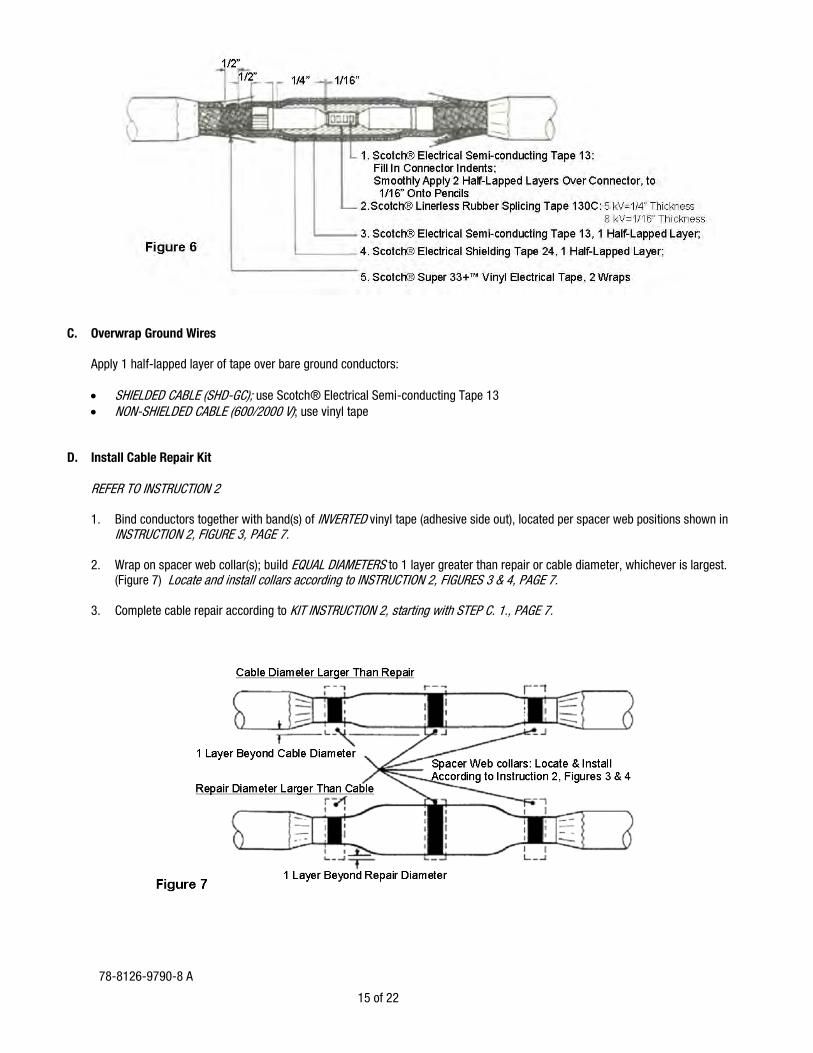
C. Overwrap Ground Wires Apply 1 half-lapped layer of tape over bare ground conductors:
• SHIELDED CABLE (SHD-GC); use Scotch® Electrical Semi-conducting Tape 13 • NON-SHIELDED CABLE (600/2000 V); use vinyl tape
D. Install Cable Repair Kit REFER TO INSTRUCTION 2 1. Bind conductors together with band(s) of INVERTED vinyl tape (adhesive side out), located per spacer web positions shown in
INSTRUCTION 2, FIGURE 3, PAGE 7. 2. Wrap on spacer web collar(s); build EQUAL DIAMETERS to 1 layer greater than repair or cable diameter, whichever is largest.
(Figure 7) Locate and install collars according to INSTRUCTION 2, FIGURES 3 & 4, PAGE 7. 3. Complete cable repair according to KIT INSTRUCTION 2, starting with STEP C. 1., PAGE 7.
78-8126-9790-8 A

13 of 22
Instruction 4 - Conductor Repair For cable repair where one conductor has been severed A. Prepare Cable Jacket 1. Position cable to eliminate bending or sagging of repair area. 2. Remove entire cable jacket from repair area, for a length not exceeding that shown in
Figure 1. NOTE: ALLOW ADEQUATE REPAIR LENGTH FOR DIMENSIONS SHOWN IN DRAWINGS. 3. FULLY taper jacket ends: 1” (25 mm) for jackets less than 3/16” (5mm) thick 2” (50 mm) for jackets of 3/16” (5 mm) and thicker 4. THOROUGHLY scuff cable jacket ends for an equal distance on each side of repair area; total length of repair area plus the
scuffs should exceed the mold’s overall length. B. Repair Damaged Conductor 1. 600/2000 Volt Portable Cable (Non-Shielded) (Figures 1 & 2) Additional Materials Required: Scotch® Linerless Rubber Splicing Tape 130C Connector
NOTE: USE STANDARD CABLE PREPARATION PRACTICES 2. 600/2000 Volt Shielded Portable Cable (Figures 3 & 4) Additional Materials Required: Scotch® Linerless Rubber Splicing Tape 130C
Scotch® Electrical Shielding Tape 24 Scotch® Super 33+™ Vinyl Electrical Tape
NOTE: USE STANDARD CABLE PREPARATION PRACTICES 78-8126-9790-8 A

14 of 22
3. 5 & 8 kV Shielded Cable Type SHD-GC, SH-D, MP-GC and MP (Figures 5 & 6) Additional Materials Required: Scotch® Electrical Semi-conducting Tape 13
Scotch® Linerless Rubber Splicing Tape 130C Scotch® Electrical Shielding Tape 24 Scotch® Super 33+™ Vinyl Electrical Tape 3M™ Scotchlok™ Copper Compression Connectors, 10000 Series
Optional materials: 3M™ Cable Cleaning Preparation Kit CC-2 or Scotch® Electrician’s Abrasive Roll A-3
NOTE: USE STANDARD H.V. CABLE PREPARATION PRACTICES
78-8126-9790-8 A
15 of 22
C. Overwrap Ground Wires Apply 1 half-lapped layer of tape over bare ground conductors:
• SHIELDED CABLE (SHD-GC); use Scotch® Electrical Semi-conducting Tape 13 • NON-SHIELDED CABLE (600/2000 V); use vinyl tape
D. Install Cable Repair Kit REFER TO INSTRUCTION 2 1. Bind conductors together with band(s) of INVERTED vinyl tape (adhesive side out), located per spacer web positions shown in
INSTRUCTION 2, FIGURE 3, PAGE 7. 2. Wrap on spacer web collar(s); build EQUAL DIAMETERS to 1 layer greater than repair or cable diameter, whichever is largest.
(Figure 7) Locate and install collars according to INSTRUCTION 2, FIGURES 3 & 4, PAGE 7. 3. Complete cable repair according to KIT INSTRUCTION 2, starting with STEP C. 1., PAGE 7.
78-8126-9790-8 A

16 of 22
Instruction 5 – 600/2000 Volt Portable Cable Splice For splicing 3-conductor portable cable, shielded or non-shielded A. Prepare Cable Jacket 1. Position cable to eliminate bending or sagging of repair area. 2. Remove entire cable jacket from splice area, for a length not exceeding that shown in Figure 1. NOTE: ALLOW ADEQUATE REPAIR LENGTH FOR DIMENSIONS SHOWN IN DRAWINGS. 3. FULLY taper ends: 1” (25 mm) for jackets less than 3/16” (5mm) thick 2” (50 mm) for jackets of 3/16” (5 mm) and thicker 4. THOROUGHLY scuff cable jacket ends for an equal distance on each side of splice area; total length of splice area plus the
scuffs should exceed the mold’s overall length. B. Splice Conductors 1. 600/2000 Volt Portable Cable (Non-Shielded) (Figures 1 & 2) Additional Materials Required: Scotch® Linerless Rubber Splicing Tape 130C Connectors (for power conductors, ground wires and ground check)
NOTE: USE STANDARD CABLE PREPARATION PRACTICES
78-8126-9790-8 A

17 of 22
2. 600/2000 Volt Shielded Portable Cable (Figures 3 & 4) Additional Materials Required: Scotch® Linerless Rubber Splicing Tape 130C
Scotch® Electrical Shielding Tape 24 Scotch® Super 33+™ Vinyl Electrical Tape Connectors (for power conductors, ground wires and ground check)
NOTE: USE STANDARD CABLE PREPARATION PRACTICES C. Overwrap Ground Wires Apply 1 half-lapped layer of tape over bare ground conductors:
• SHIELDED CABLE (SHD-GC); use Scotch® Electrical Semi-conducting Tape 13 • NON-SHIELDED CABLE (600/2000 V); use vinyl tape
78-8126-9790-8 A
18 of 22
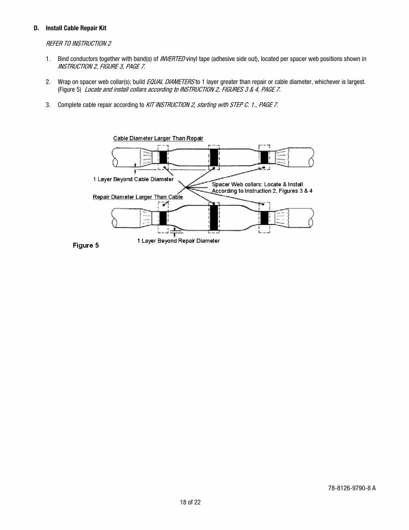
D. Install Cable Repair Kit REFER TO INSTRUCTION 2 1. Bind conductors together with band(s) of INVERTED vinyl tape (adhesive side out), located per spacer web positions shown in
INSTRUCTION 2, FIGURE 3, PAGE 7. 2. Wrap on spacer web collar(s); build EQUAL DIAMETERS to 1 layer greater than repair or cable diameter, whichever is largest.
(Figure 5) Locate and install collars according to INSTRUCTION 2, FIGURES 3 & 4, PAGE 7. 3. Complete cable repair according to KIT INSTRUCTION 2, starting with STEP C. 1., PAGE 7.
78-8126-9790-8 A

19 of 22
Cable Crotch Seal (Trifurcation) A. Prepare Cable 1. Remove cable jacket; field determine removal length according to
termination and spacing requirements, etc. (Figure 1) 2. THOROUGHLY scuff jacket end as follows: M-20 Kit = 6” (150 mm) M-30 Kit = 8” (200 mm) M-40 Kit = 9” (230 mm) Clean dust from scuffed area. (Figure 1) 3. IF individual power conductors and grounds are to be jacketed, apply jacketing now.
TAPE METHOD: Starting 3/4” (20 mm) from cable jacket, overwrap each conductor and ground with 2 half-lapped layers of Scotch® Linerless Rubber Splicing Tape 130C; leave proper distance on ends of power conductors for installation of terminations. Apply 2 half-lapped layers of Scotch® Super 33+™ Vinyl Electrical Tape over the Scotch® Tape 130C.
4. TERMINATIONS: May be installed now or after completion of cable crotch seal. TERMINATION METHODS:
TAPE: Scotch® Tape Termination Kits 5700 Series. (An overwrap of Scotch® Self-Fusing Silicone Rubber Electrical Tape 70 is recommended for tracking protection.)
MOLDED RUBBER: 3M™ Outdoor Termination Kits, 5600 Series B. Install 3M™ Cable Repair Spacer Web 1. Wrap on 3M™ Spacer Web to form collar(s) per Figure 2; build it 2 layers thick and cut off. 78-8126-9790-8 A

20 of 22
2. Split end of 3M™ Cable Repair Spacer Web and press into sides of collar to hold in place. (Figure 3) C. Install Mold
1. Modify mold by cutting off at outside edge of a mold hole. (Figure 4) NOTE: THE SHORT CUT OFF END BECOMES THE CABLE CROTCH SEAL MOLD. (Figure 4) 2. Seal the vent slits on outside of mold with a length of vinyl tape. 3. With cable straight, CENTER modified mold over spacer web collar. Wrap snugly around, tucking one edge under. (Figure 5)
NOTE: TUCKED EDGE MUST BE STRAIGHT TO FORM A SEAL 4. Position a funnel support over on the mold, locating it over the spacer web collar. Secure firmly with a mold strap. (Figure 5)
NOTE: MOLD, FUNNEL SUPPORT AND MOLD STRAP MAY BE MOVED AROUND AT THIS TIME, TO ADJUST FOR FINAL POSITION OF BEING CENTERED OVER THE SPACER WEB COLLAR. (Figure 5)
78-8126-9790-8 A

21 of 22
5. Bundle mold’s notched end evenly around cable, maintaining cable centering. Starting 1/2” (12 mm) on cable jacket, apply 1 half-lapped layer of Scotch® Linerless Rubber Splicing Tape 130C over the mold’s notched ends. (Figure 5)
NOTE: APPLY SCOTCH® LINERLESS RUBBER SPLICING TAPE 130C WITH TACKY SIDE UP, WITH ONLY ENOUGH TENSION
TO CONFORM TO MOLD. (Figure 5) 6. With cable end mounted vertically, arrange individual conductors and grounds into final position. Allow a minimum clearance of
1/4” (6,4 mm) from edge of mold body. (Main Illustration) D. Pour Compound 1. Premix BLACK side of 3M™ Scotchcast™ Flame-Retardant Compound 2131 pouch by squeezing to a smooth consistency and
uniform color. 2. Firmly grasp each flat side of the closed mixing pouch near the center barrier; at the same time, pull sides of barrier apart and
roll sides of thumbs through barrier. Break the barrier all the way across to the side seals. (Figure 6) 3. Alternately squeeze ends of pouch forcing compound rapidly back and forth and strip compound from corners of pouch between
fingers. Mix until color is completely uniform – 30 to 40 VIGOROUS SQUEEZES. DO NOT EXCEED 1 MINUTE. (Figure 7) 4. Clip off a corner of pouch and immediately pour into top of mold. Fill mold to top edge. 5. Allow compound to cure.
NOTE: REPAIR MAY BE DE-MOLDED WHEN COMPOUND IS NO LONGER TACKY. Typical Cure Time: 16 – 24 hrs. @ 70ºF (21ºC) 24 – 30 hrs. @ 50ºF (10ºC) 36 hrs. @ 32ºF (0ºC)
Typical De-mold Time: 1.5 hrs. @ 70ºF (21ºC) 4 hrs. @ 50ºF (10ºC) 6 – 8 hrs. @ 32ºF (0ºC)
NOTE: VALUES ARE TYPICAL, NOT TO BE CONSIDERED MINIMUM OR MAXIMUM. ALWAYS CONFIRM BASED ON TACK AND HARDNESS OF COMPOUND.
78-8126-9790-8 A

22 of 22
E. De-mold 1. Remove mold strap and funnel support. 2. Remove Scotch® Linerless Rubber Splicing Tape 130C and mold end. 3. Remove mold from cable crotch seal. 3M, Scotch, Scotchcast, Scotchlok and Super 33+ are trademarks of 3M Company.
Important Notice: All statements, technical information, and recommendations related to 3M’s products are based on information believed to be reliable, but the accuracy or completeness is not guaranteed. Before using this product, you must evaluate it and determine if it is suitable for your intended application. You assume all risks and liability associated with such use. Any statements related to the product, which are not contained in 3M’s current publications, or any contrary statements contained on your purchase order, shall have no force or effect unless expressly agreed upon, in writing, by an authorized officer of 3M. Warranty; Limited Remedy; Limited Liability: This product will be free from defects in material and manufacture at the time of purchase. 3M MAKES NO OTHER WARRANTIES INCLUDING, BUT NOT LIMITED TO, ANY IMPLIED WARRANTY OF MERCHANTABILITY OR FITNESS FOR A PARTICULAR PURPOSE. If this product is defective within the warranty period stated above, your exclusive remedy shall be, at 3M’s option, to replace or repair the 3M product or refund the purchase price of the 3M product. Except where prohibited by law, 3M will not be liable for any indirect, special, incidental or consequential loss or damage arising from this 3M product, regardless of the legal theory asserted.
Electrical Markets Division 6801 River Place Blvd. Austin, TX 78726-9000 800-245-3573 Please Recycle. Printed in USA. Fax 800-245-0329 © 3M 2011 All Rights Reserved. www.3M.com/electrical 78-8126-9790-8 A