3M Personal Safety Division NoisePromultimedia.3m.com/mws/media/778904O/noisepro-noise... · 3MTM...
119
3M Personal Safety Division NoisePro ™ Personal Noise Dosimeter NoisePro ™ User Manual
Transcript of 3M Personal Safety Division NoisePromultimedia.3m.com/mws/media/778904O/noisepro-noise... · 3MTM...
3M Personal Safety Division NoisePro™ Personal Noise Dosimeter
NoisePro™ User Manual
3MTM NoisePro Personal Noise Dosimeter
CopyrightThis document is copyrighted by Quest Technologies, a 3M company. Permission is hereby granted to copy and distribute this manual provided that this Copyright Page is included. This grant does not include permission to modify the manual’s text or illustrations in any way. This manual may not be translated without obtaining permission in advance.
UpdatesIn the interests of continuous product improvements, 3M Quest Technologies reserves the right to make changes to product specifi cations without notice. To understand the latest updates that have been implemented into this product and to download the most current version of this user manual, visit our web site at www.3M.com/detection.
ApprovalsUL, cUL, MSHA, Ex and ATEX intrinsic safety approvals. Ex approval is in accordance with the ATEX Directive.
C US
LISTED
i
053-379, Rev E
3MTM NoisePro Personal Noise Dosimeter
Dangers, Warnings, Cautions & Battery
Danger! Failure to observe the following procedures may result in serious personal injury • To reduce the risk of explosion, do not mix used batteries with unused batteries or mix batteries from different manufacturers. • Contains built-in lithium battery (for internal date and time back-up). Do not incinerate or dispose of in fi re. Do not disassemble, alter, or re-construct.
Warning! Failure to observe the following procedures could damage the instrument. • Read the manual before operation. • Do not store in temperatures exceeding 60°C (140°F). • Do not immerse in liquids. • Condensation may damage your instrument. • To reduce the risk of ignition of a fl ammable or explosive atmosphere, batteries must be changed only in a location known to be non-hazardous. • Substitution of components may impair the accuracy of the instrument. Repair should be performed by authorized service personnel only.
Caution! General • The battery in this instrument has limited shelf-life, even if never used. • A non-condensing environment is required for proper measurements. • Battery run-time may be reduced when operating at lower than 0°C (32°F) temperatures. Batteries and StorageTo reduce the risk of “AA” Alkaline batteries for leaking, it is recommended to: • Remove the batteries from the housing whenever the NoisePro is stored for approximately 2 to 3 weeks or longer. • Replace the batteries when LOBAT message appears on the display of the NoisePro. • For more information on replacing the batteries or recommended battery types, please refer to Chapter 10, “Replacing batteries” and “Approved batteries”.
Intended Use: The NoisePro is intended to measure sound pressure levels in air and provide personal noise exposure measurements. Consult your company’s safety professional for local standards, or call 3M at 1-800-243-4630.
ii DANGERS, WARNINGS, & BATTERIES
053-379, Rev E
CONTENTS
053-379, Rev D
Table of ContentsTrademarks . . . . . . . . . . . . . . . . . . . . . . . . . . . . . . . . . . . . . . . . . . . . . . iApprovals . . . . . . . . . . . . . . . . . . . . . . . . . . . . . . . . . . . . . . . . . . . . . . . iCopyright . . . . . . . . . . . . . . . . . . . . . . . . . . . . . . . . . . . . . . . . . . . . . . . iUpdates . . . . . . . . . . . . . . . . . . . . . . . . . . . . . . . . . . . . . . . . . . . . . . . . . i
Warnings Concerning Safe Operation . . . . . . . . . . . . . . . . . . . . . . . . . iiTake care when changing batteries . . . . . . . . . . . . . . . . . . . . . . . . . . . iiDo not substitute components . . . . . . . . . . . . . . . . . . . . . . . . . . . . . . . ii
Chapter 1: Introduction . . . . . . . . . . . . . . . . . . . . . . . . . . . . . . . . . . . . . . . . .1Noise dosimetry . . . . . . . . . . . . . . . . . . . . . . . . . . . . . . . . . . . . . . . . . . . . . 1
Wide dynamic range of sound . . . . . . . . . . . . . . . . . . . . . . . . . . . . . . . .1Standards . . . . . . . . . . . . . . . . . . . . . . . . . . . . . . . . . . . . . . . . . . . . . . . .1
NoisePro models . . . . . . . . . . . . . . . . . . . . . . . . . . . . . . . . . . . . . . . . . . . . 1About studies and sessions . . . . . . . . . . . . . . . . . . . . . . . . . . . . . . . . . . . . 2
Logging . . . . . . . . . . . . . . . . . . . . . . . . . . . . . . . . . . . . . . . . . . . . . . . . .2Area monitoring. . . . . . . . . . . . . . . . . . . . . . . . . . . . . . . . . . . . . . . . . . . . . 2
Session time line . . . . . . . . . . . . . . . . . . . . . . . . . . . . . . . . . . . . . . . . . .3Run Time . . . . . . . . . . . . . . . . . . . . . . . . . . . . . . . . . . . . . . . . . . . . . . . .4
Use the cover . . . . . . . . . . . . . . . . . . . . . . . . . . . . . . . . . . . . . . . . . . . . . . . 4NoisePro case and controls . . . . . . . . . . . . . . . . . . . . . . . . . . . . . . . . . . . .
Chapter 2: First time use . . . . . . . . . . . . . . . . . . . . . . . . . . . . . . . . . . . . . . . .7Assembling . . . . . . . . . . . . . . . . . . . . . . . . . . . . . . . . . . . . . . . . . . . . . . . . 7
DLX-1 . . . . . . . . . . . . . . . . . . . . . . . . . . . . . . . . . . . . . . . . . . . . . . . . . .7All other NoisePro models. . . . . . . . . . . . . . . . . . . . . . . . . . . . . . . . . . .8
NoisePro keys . . . . . . . . . . . . . . . . . . . . . . . . . . . . . . . . . . . . . . . . . . . . . . 8Powering on/off . . . . . . . . . . . . . . . . . . . . . . . . . . . . . . . . . . . . . . . . . . . . . 9Verifying battery power. . . . . . . . . . . . . . . . . . . . . . . . . . . . . . . . . . . . . . . 9Establishing operating conditions . . . . . . . . . . . . . . . . . . . . . . . . . . . . . . . 9
®
053-379, Rev E
CONTENTSiv
053-379, Rev D
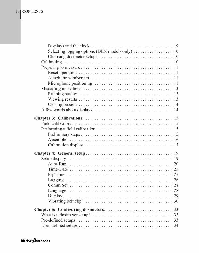
Displays and the clock . . . . . . . . . . . . . . . . . . . . . . . . . . . . . . . . . . . . . .9Selecting logging options (DLX models only) . . . . . . . . . . . . . . . . . .10Choosing dosimeter setups . . . . . . . . . . . . . . . . . . . . . . . . . . . . . . . . .10
Calibrating . . . . . . . . . . . . . . . . . . . . . . . . . . . . . . . . . . . . . . . . . . . . . . . . 10Preparing to measure . . . . . . . . . . . . . . . . . . . . . . . . . . . . . . . . . . . . . . . . 11
Reset operation . . . . . . . . . . . . . . . . . . . . . . . . . . . . . . . . . . . . . . . . . .11Attach the windscreen . . . . . . . . . . . . . . . . . . . . . . . . . . . . . . . . . . . . .11Microphone positioning. . . . . . . . . . . . . . . . . . . . . . . . . . . . . . . . . . . .11
Measuring noise levels. . . . . . . . . . . . . . . . . . . . . . . . . . . . . . . . . . . . . . . 13Running studies . . . . . . . . . . . . . . . . . . . . . . . . . . . . . . . . . . . . . . . . . .13Viewing results . . . . . . . . . . . . . . . . . . . . . . . . . . . . . . . . . . . . . . . . . .13Closing sessions . . . . . . . . . . . . . . . . . . . . . . . . . . . . . . . . . . . . . . . . . .14
A few words about displays. . . . . . . . . . . . . . . . . . . . . . . . . . . . . . . . . . . 14
Chapter 3: Calibrations . . . . . . . . . . . . . . . . . . . . . . . . . . . . . . . . . . . . . . . .15Field calibrator . . . . . . . . . . . . . . . . . . . . . . . . . . . . . . . . . . . . . . . . . . . . . 15Performing a field calibration . . . . . . . . . . . . . . . . . . . . . . . . . . . . . . . . . 15
Preliminary steps . . . . . . . . . . . . . . . . . . . . . . . . . . . . . . . . . . . . . . . . .15Assemble . . . . . . . . . . . . . . . . . . . . . . . . . . . . . . . . . . . . . . . . . . . . . . .16Calibration display. . . . . . . . . . . . . . . . . . . . . . . . . . . . . . . . . . . . . . . .17
Chapter 4: General setup . . . . . . . . . . . . . . . . . . . . . . . . . . . . . . . . . . . . . . .19Setup display . . . . . . . . . . . . . . . . . . . . . . . . . . . . . . . . . . . . . . . . . . . . . . 19
Auto-Run . . . . . . . . . . . . . . . . . . . . . . . . . . . . . . . . . . . . . . . . . . . . . . .20Time-Date . . . . . . . . . . . . . . . . . . . . . . . . . . . . . . . . . . . . . . . . . . . . . .25Prj Time . . . . . . . . . . . . . . . . . . . . . . . . . . . . . . . . . . . . . . . . . . . . . . . .25Logging . . . . . . . . . . . . . . . . . . . . . . . . . . . . . . . . . . . . . . . . . . . . . . . .26Comm Set . . . . . . . . . . . . . . . . . . . . . . . . . . . . . . . . . . . . . . . . . . . . . .28Language . . . . . . . . . . . . . . . . . . . . . . . . . . . . . . . . . . . . . . . . . . . . . . .28Display . . . . . . . . . . . . . . . . . . . . . . . . . . . . . . . . . . . . . . . . . . . . . . . . .29Vibrating belt clip . . . . . . . . . . . . . . . . . . . . . . . . . . . . . . . . . . . . . . . .30
Chapter 5: Configuring dosimeters. . . . . . . . . . . . . . . . . . . . . . . . . . . . . . .33What is a dosimeter setup? . . . . . . . . . . . . . . . . . . . . . . . . . . . . . . . . . . . 33Pre-defined setups . . . . . . . . . . . . . . . . . . . . . . . . . . . . . . . . . . . . . . . . . . 33User-defined setups . . . . . . . . . . . . . . . . . . . . . . . . . . . . . . . . . . . . . . . . . 34
053-379, Rev E
CONTENTS v
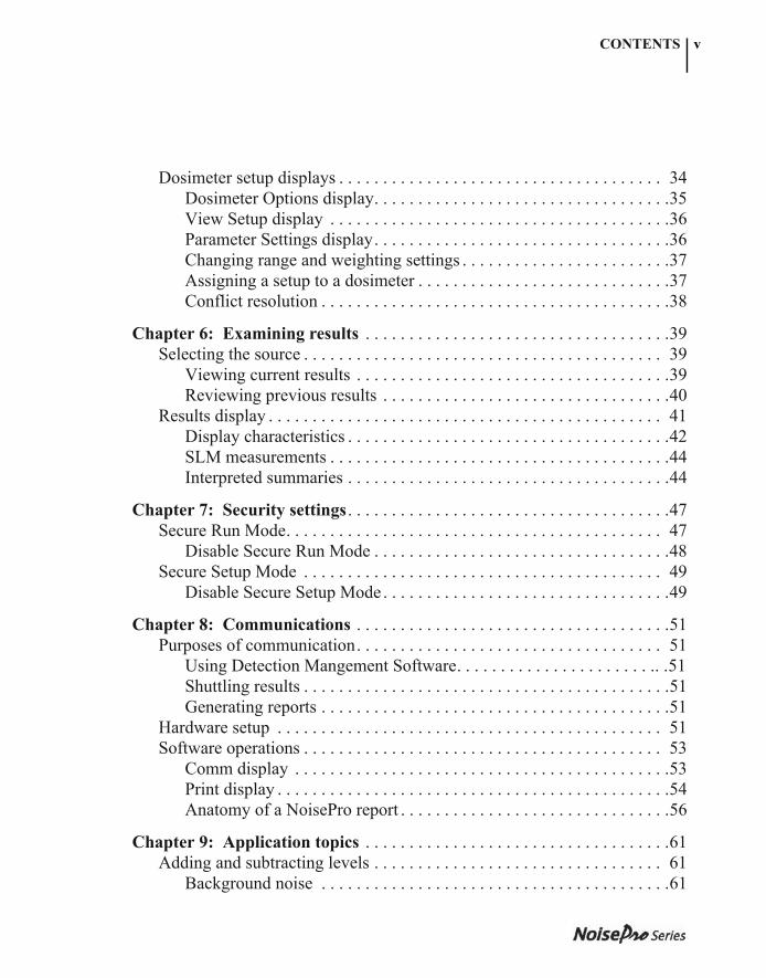
Dosimeter setup displays . . . . . . . . . . . . . . . . . . . . . . . . . . . . . . . . . . . . . 34Dosimeter Options display. . . . . . . . . . . . . . . . . . . . . . . . . . . . . . . . . .35View Setup display . . . . . . . . . . . . . . . . . . . . . . . . . . . . . . . . . . . . . . .36Parameter Settings display. . . . . . . . . . . . . . . . . . . . . . . . . . . . . . . . . .36Changing range and weighting settings . . . . . . . . . . . . . . . . . . . . . . . .37Assigning a setup to a dosimeter . . . . . . . . . . . . . . . . . . . . . . . . . . . . .37Conflict resolution . . . . . . . . . . . . . . . . . . . . . . . . . . . . . . . . . . . . . . . .38
Chapter 6: Examining results . . . . . . . . . . . . . . . . . . . . . . . . . . . . . . . . . . .39Selecting the source . . . . . . . . . . . . . . . . . . . . . . . . . . . . . . . . . . . . . . . . . 39
Viewing current results . . . . . . . . . . . . . . . . . . . . . . . . . . . . . . . . . . . .39Reviewing previous results . . . . . . . . . . . . . . . . . . . . . . . . . . . . . . . . .40
Results display . . . . . . . . . . . . . . . . . . . . . . . . . . . . . . . . . . . . . . . . . . . . . 41Display characteristics . . . . . . . . . . . . . . . . . . . . . . . . . . . . . . . . . . . . .42SLM measurements . . . . . . . . . . . . . . . . . . . . . . . . . . . . . . . . . . . . . . .44Interpreted summaries . . . . . . . . . . . . . . . . . . . . . . . . . . . . . . . . . . . . .44
Chapter 7: Security settings . . . . . . . . . . . . . . . . . . . . . . . . . . . . . . . . . . . . .47Secure Run Mode. . . . . . . . . . . . . . . . . . . . . . . . . . . . . . . . . . . . . . . . . . . 47
Disable Secure Run Mode . . . . . . . . . . . . . . . . . . . . . . . . . . . . . . . . . .48Secure Setup Mode . . . . . . . . . . . . . . . . . . . . . . . . . . . . . . . . . . . . . . . . . 49
Disable Secure Setup Mode . . . . . . . . . . . . . . . . . . . . . . . . . . . . . . . . .49
Chapter 8: Communications . . . . . . . . . . . . . . . . . . . . . . . . . . . . . . . . . . . .51Purposes of communication. . . . . . . . . . . . . . . . . . . . . . . . . . . . . . . . . . . 51
Using Detection Mangement Software. . . . . . . . . . . . . . . . . . . . . . .. .51Shuttling results . . . . . . . . . . . . . . . . . . . . . . . . . . . . . . . . . . . . . . . . . .51Generating reports . . . . . . . . . . . . . . . . . . . . . . . . . . . . . . . . . . . . . . . .51
Hardware setup . . . . . . . . . . . . . . . . . . . . . . . . . . . . . . . . . . . . . . . . . . . . 51Software operations . . . . . . . . . . . . . . . . . . . . . . . . . . . . . . . . . . . . . . . . . 53
Comm display . . . . . . . . . . . . . . . . . . . . . . . . . . . . . . . . . . . . . . . . . . .53Print display . . . . . . . . . . . . . . . . . . . . . . . . . . . . . . . . . . . . . . . . . . . . .54Anatomy of a NoisePro report . . . . . . . . . . . . . . . . . . . . . . . . . . . . . . .56
Chapter 9: Application topics . . . . . . . . . . . . . . . . . . . . . . . . . . . . . . . . . . .61Adding and subtracting levels . . . . . . . . . . . . . . . . . . . . . . . . . . . . . . . . . 61
Background noise . . . . . . . . . . . . . . . . . . . . . . . . . . . . . . . . . . . . . . . .61

053-379, Rev E
CONTENTSvi
053-379, Rev D
Combining noise sources . . . . . . . . . . . . . . . . . . . . . . . . . . . . . . . . . . .62Noise Floor . . . . . . . . . . . . . . . . . . . . . . . . . . . . . . . . . . . . . . . . . . . . .63
Chapter 10: Maintenance. . . . . . . . . . . . . . . . . . . . . . . . . . . . . . . . . . . . . . .65Approved batteries . . . . . . . . . . . . . . . . . . . . . . . . . . . . . . . . . . . . . . . . . . 65Replacing batteries. . . . . . . . . . . . . . . . . . . . . . . . . . . . . . . . . . . . . . . . . . 65Exchanging belt clips. . . . . . . . . . . . . . . . . . . . . . . . . . . . . . . . . . . . . . . . 67
Chapter 11: Technical support. . . . . . . . . . . . . . . . . . . . . . . . . . . . . . . . . . .69Troubleshooting . . . . . . . . . . . . . . . . . . . . . . . . . . . . . . . . . . . . . . . . . . . . 69
Blank display . . . . . . . . . . . . . . . . . . . . . . . . . . . . . . . . . . . . . . . . . . . .69General calibration problems. . . . . . . . . . . . . . . . . . . . . . . . . . . . . . . .69Pre-calibration value not saved . . . . . . . . . . . . . . . . . . . . . . . . . . . . . .69Post-calibration discrepancy . . . . . . . . . . . . . . . . . . . . . . . . . . . . . . . .69Unit is erratic . . . . . . . . . . . . . . . . . . . . . . . . . . . . . . . . . . . . . . . . . . . .70Clock settings lost . . . . . . . . . . . . . . . . . . . . . . . . . . . . . . . . . . . . . . . .70Belt clip vibrator not working . . . . . . . . . . . . . . . . . . . . . . . . . . . . . . .70Belt clip vibrator won’t turn off. . . . . . . . . . . . . . . . . . . . . . . . . . . . . .70Communications not working . . . . . . . . . . . . . . . . . . . . . . . . . . . . . . .70Mic error . . . . . . . . . . . . . . . . . . . . . . . . . . . . . . . . . . . . . . . . . . . . . . .70Battery error (PFR restore) . . . . . . . . . . . . . . . . . . . . . . . . . . . . . . . . .70
Factory service . . . . . . . . . . . . . . . . . . . . . . . . . . . . . . . . . . . . . . . . . . . . . 71
Appendix A: Glossary . . . . . . . . . . . . . . . . . . . . . . . . . . . . . . . . . . . . . . . . .73Basic Descriptors . . . . . . . . . . . . . . . . . . . . . . . . . . . . . . . . . . . . . . . . .73Criterion Level (CL) . . . . . . . . . . . . . . . . . . . . . . . . . . . . . . . . . . . . . .73Criterion Time . . . . . . . . . . . . . . . . . . . . . . . . . . . . . . . . . . . . . . . . . . .73Decibel (dB). . . . . . . . . . . . . . . . . . . . . . . . . . . . . . . . . . . . . . . . . . . . .73Dose . . . . . . . . . . . . . . . . . . . . . . . . . . . . . . . . . . . . . . . . . . . . . . . . . . .74Exceedence Levels. . . . . . . . . . . . . . . . . . . . . . . . . . . . . . . . . . . . . . . .74Exchange Rate (ER). . . . . . . . . . . . . . . . . . . . . . . . . . . . . . . . . . . . . . .74Hearing Conservation (HC) . . . . . . . . . . . . . . . . . . . . . . . . . . . . . . . . .75Hertz (Hz) . . . . . . . . . . . . . . . . . . . . . . . . . . . . . . . . . . . . . . . . . . . . . .75IEC/ISO Descriptors . . . . . . . . . . . . . . . . . . . . . . . . . . . . . . . . . . . . . .75LAVG . . . . . . . . . . . . . . . . . . . . . . . . . . . . . . . . . . . . . . . . . . . . . . . . .76LDN . . . . . . . . . . . . . . . . . . . . . . . . . . . . . . . . . . . . . . . . . . . . . . . . . . .77
053-379, Rev E
CONTENTS vii
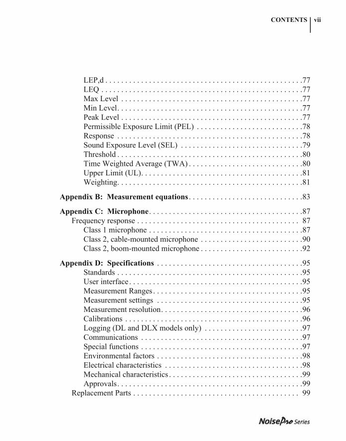
LEP,d . . . . . . . . . . . . . . . . . . . . . . . . . . . . . . . . . . . . . . . . . . . . . . . . . .77LEQ . . . . . . . . . . . . . . . . . . . . . . . . . . . . . . . . . . . . . . . . . . . . . . . . . . .77Max Level . . . . . . . . . . . . . . . . . . . . . . . . . . . . . . . . . . . . . . . . . . . . . .77Min Level. . . . . . . . . . . . . . . . . . . . . . . . . . . . . . . . . . . . . . . . . . . . . . .77Peak Level . . . . . . . . . . . . . . . . . . . . . . . . . . . . . . . . . . . . . . . . . . . . . .77Permissible Exposure Limit (PEL) . . . . . . . . . . . . . . . . . . . . . . . . . . .78Response . . . . . . . . . . . . . . . . . . . . . . . . . . . . . . . . . . . . . . . . . . . . . . .78Sound Exposure Level (SEL) . . . . . . . . . . . . . . . . . . . . . . . . . . . . . . .79Threshold . . . . . . . . . . . . . . . . . . . . . . . . . . . . . . . . . . . . . . . . . . . . . . .80Time Weighted Average (TWA) . . . . . . . . . . . . . . . . . . . . . . . . . . . . .80Upper Limit (UL). . . . . . . . . . . . . . . . . . . . . . . . . . . . . . . . . . . . . . . . .81Weighting. . . . . . . . . . . . . . . . . . . . . . . . . . . . . . . . . . . . . . . . . . . . . . .81
Appendix B: Measurement equations . . . . . . . . . . . . . . . . . . . . . . . . . . . . .83
Appendix C: Microphone. . . . . . . . . . . . . . . . . . . . . . . . . . . . . . . . . . . . . . .87Frequency response . . . . . . . . . . . . . . . . . . . . . . . . . . . . . . . . . . . . . . . . . 87
Class 1 microphone . . . . . . . . . . . . . . . . . . . . . . . . . . . . . . . . . . . . . . .87Class 2, cable-mounted microphone . . . . . . . . . . . . . . . . . . . . . . . . . .90Class 2, boom-mounted microphone . . . . . . . . . . . . . . . . . . . . . . . . . .92
Appendix D: Specifications . . . . . . . . . . . . . . . . . . . . . . . . . . . . . . . . . . . . .95Standards . . . . . . . . . . . . . . . . . . . . . . . . . . . . . . . . . . . . . . . . . . . . . . .95User interface . . . . . . . . . . . . . . . . . . . . . . . . . . . . . . . . . . . . . . . . . . . .95Measurement Ranges . . . . . . . . . . . . . . . . . . . . . . . . . . . . . . . . . . . . . .95Measurement settings . . . . . . . . . . . . . . . . . . . . . . . . . . . . . . . . . . . . .95Measurement resolution. . . . . . . . . . . . . . . . . . . . . . . . . . . . . . . . . . . .96Calibrations . . . . . . . . . . . . . . . . . . . . . . . . . . . . . . . . . . . . . . . . . . . . .96Logging (DL and DLX models only) . . . . . . . . . . . . . . . . . . . . . . . . .97Communications . . . . . . . . . . . . . . . . . . . . . . . . . . . . . . . . . . . . . . . . .97Special functions . . . . . . . . . . . . . . . . . . . . . . . . . . . . . . . . . . . . . . . . .97Environmental factors . . . . . . . . . . . . . . . . . . . . . . . . . . . . . . . . . . . . .98Electrical characteristics . . . . . . . . . . . . . . . . . . . . . . . . . . . . . . . . . . .98Mechanical characteristics . . . . . . . . . . . . . . . . . . . . . . . . . . . . . . . . . .99Approvals. . . . . . . . . . . . . . . . . . . . . . . . . . . . . . . . . . . . . . . . . . . . . . .99
Replacement Parts . . . . . . . . . . . . . . . . . . . . . . . . . . . . . . . . . . . . . . . . . . 99
053-379, Rev E
CONTENTSviii
053-379, Rev D
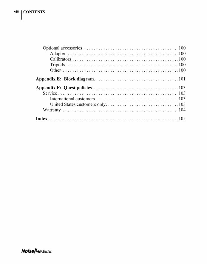
Optional accessories . . . . . . . . . . . . . . . . . . . . . . . . . . . . . . . . . . . . . . . 100Adapter. . . . . . . . . . . . . . . . . . . . . . . . . . . . . . . . . . . . . . . . . . . . . . . .100Calibrators . . . . . . . . . . . . . . . . . . . . . . . . . . . . . . . . . . . . . . . . . . . . .100Tripods . . . . . . . . . . . . . . . . . . . . . . . . . . . . . . . . . . . . . . . . . . . . . . . .100Other . . . . . . . . . . . . . . . . . . . . . . . . . . . . . . . . . . . . . . . . . . . . . . . . .100
Appendix E: Block diagram. . . . . . . . . . . . . . . . . . . . . . . . . . . . . . . . . . . .101
Appendix F: Quest policies . . . . . . . . . . . . . . . . . . . . . . . . . . . . . . . . . . . .103Service . . . . . . . . . . . . . . . . . . . . . . . . . . . . . . . . . . . . . . . . . . . . . . . . . . 103
International customers . . . . . . . . . . . . . . . . . . . . . . . . . . . . . . . . . . .103United States customers only. . . . . . . . . . . . . . . . . . . . . . . . . . . . . . .103
Warranty . . . . . . . . . . . . . . . . . . . . . . . . . . . . . . . . . . . . . . . . . . . . . . . . 104
Index . . . . . . . . . . . . . . . . . . . . . . . . . . . . . . . . . . . . . . . . . . . . . . . . . . . . . . .105
053-379, Rev E
LISTS
053-379, Rev D
List of Figures1–1 Session time line . . . . . . . . . . . . . . . . . . . . . . . . . . . . . . . . . . . . . . . . . . . .32–1 Shoulder-mounted microphone . . . . . . . . . . . . . . . . . . . . . . . . . . . . . . .122–2 Start display and softkeys . . . . . . . . . . . . . . . . . . . . . . . . . . . . . . . . . . . .143–1 Calibration orientations and assembly . . . . . . . . . . . . . . . . . . . . . . . . . .163–2 Calibration display . . . . . . . . . . . . . . . . . . . . . . . . . . . . . . . . . . . . . . . . .173–3 Calibration Save display . . . . . . . . . . . . . . . . . . . . . . . . . . . . . . . . . . . . .184–1 DLX model Setup display . . . . . . . . . . . . . . . . . . . . . . . . . . . . . . . . . . .194–2 Auto-Run display . . . . . . . . . . . . . . . . . . . . . . . . . . . . . . . . . . . . . . . . . .204–3 DLX Date Setup display . . . . . . . . . . . . . . . . . . . . . . . . . . . . . . . . . . . . .214–4 Timed Run Setup display . . . . . . . . . . . . . . . . . . . . . . . . . . . . . . . . . . . .224–5 Days of Week Setup display . . . . . . . . . . . . . . . . . . . . . . . . . . . . . . . . . .234–6 Logging Setup display . . . . . . . . . . . . . . . . . . . . . . . . . . . . . . . . . . . . . .264–7 DL and DLX Vibration Setup display . . . . . . . . . . . . . . . . . . . . . . . . . .315–1 Working with dosimeter setups (DLX displays shown) . . . . . . . . . . . . .356–1 Source Selection display . . . . . . . . . . . . . . . . . . . . . . . . . . . . . . . . . . . . .406–2 Results display . . . . . . . . . . . . . . . . . . . . . . . . . . . . . . . . . . . . . . . . . . . .416–3 Summary display . . . . . . . . . . . . . . . . . . . . . . . . . . . . . . . . . . . . . . . . . .446–4 Alert Levels (AL 1 & 2) . . . . . . . . . . . . . . . . . . . . . . . . . . . . . . . . . . . . .457–1 Security Control display . . . . . . . . . . . . . . . . . . . . . . . . . . . . . . . . . . . . .477–2 Locked Run display . . . . . . . . . . . . . . . . . . . . . . . . . . . . . . . . . . . . . . . .488–1 Infrared cable connections . . . . . . . . . . . . . . . . . . . . . . . . . . . . . . . . . . .528–2 Comm display . . . . . . . . . . . . . . . . . . . . . . . . . . . . . . . . . . . . . . . . . . . . .538–3 DLX Print display . . . . . . . . . . . . . . . . . . . . . . . . . . . . . . . . . . . . . . . . . .548–4 Header section . . . . . . . . . . . . . . . . . . . . . . . . . . . . . . . . . . . . . . . . . . . .578–5 Session section . . . . . . . . . . . . . . . . . . . . . . . . . . . . . . . . . . . . . . . . . . . .588–6 Study section . . . . . . . . . . . . . . . . . . . . . . . . . . . . . . . . . . . . . . . . . . . . .598–7 Logging section . . . . . . . . . . . . . . . . . . . . . . . . . . . . . . . . . . . . . . . . . . .609–1 Background noise correction chart . . . . . . . . . . . . . . . . . . . . . . . . . . . . .629–2 Combining measurements chart . . . . . . . . . . . . . . . . . . . . . . . . . . . . . . .6310–1 Battery replacement . . . . . . . . . . . . . . . . . . . . . . . . . . . . . . . . . . . . . . . .6610–2 Belt clip assembly . . . . . . . . . . . . . . . . . . . . . . . . . . . . . . . . . . . . . . . . . .67
®
053-379, Rev E
x LISTS
053-379, Rev D
A–1 Slow response to a tone burst . . . . . . . . . . . . . . . . . . . . . . . . . . . . . . . . .78A–2 Fast response to a tone burst . . . . . . . . . . . . . . . . . . . . . . . . . . . . . . . . . .79A–3 NoisePro weighting curves . . . . . . . . . . . . . . . . . . . . . . . . . . . . . . . . . . .82C–1 Class 1, free field, 0o, no windscreen . . . . . . . . . . . . . . . . . . . . . . . . . . .88C–2 Class 1, free field, 90o, no windscreen . . . . . . . . . . . . . . . . . . . . . . . . . .88C–3 Class 1, random incidence, no windscreen . . . . . . . . . . . . . . . . . . . . . . .89C–4 Class 1, random incidence, windscreen . . . . . . . . . . . . . . . . . . . . . . . . .89C–5 Class 2, free field, 0o, no windscreen . . . . . . . . . . . . . . . . . . . . . . . . . . .90C–6 Class 2, free field, 90o, no windscreen . . . . . . . . . . . . . . . . . . . . . . . . . .90C–7 Class 2, random incidence, no windscreen . . . . . . . . . . . . . . . . . . . . . . .91C–8 Class 2, random incidence, windscreen . . . . . . . . . . . . . . . . . . . . . . . . .91C–9 Class 2, boom, free field, 0o, no windscreen . . . . . . . . . . . . . . . . . . . . .92C–10 Class 2, boom, free field, 90o, no windscreen . . . . . . . . . . . . . . . . . . . .92C–11 Class 2, boom, random incidence, no windscreen . . . . . . . . . . . . . . . . .93C–12 Class 2, boom, random incidence, windscreen . . . . . . . . . . . . . . . . . . . .93E–1 NoisePro block diagram . . . . . . . . . . . . . . . . . . . . . . . . . . . . . . . . . . . .101
List of Tables4–1 Explanation of logging options . . . . . . . . . . . . . . . . . . . . . . . . . . . . . . . .265–1 Parametric settings for pre-defined setups . . . . . . . . . . . . . . . . . . . . . . .346–1 Setups, Alert Levels and tagged compliance indicators . . . . . . . . . . . . .46A–1 Basic and IEC/ISO descriptors compared . . . . . . . . . . . . . . . . . . . . . . . .76B–1 Variables used in the equations . . . . . . . . . . . . . . . . . . . . . . . . . . . . . . . .85
053-379, Rev E
2 INTRODUCTIONAbout studies and sessions
053-379, Rev D
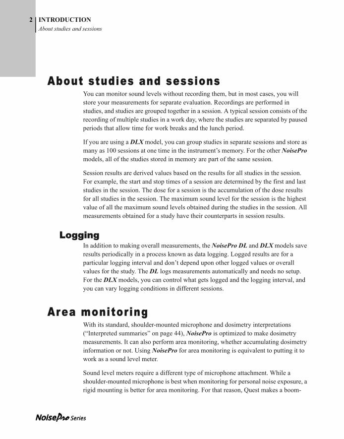
About studies and sessionsYou can monitor sound levels without recording them, but in most cases, you will store your measurements for separate evaluation. Recordings are performed in studies, and studies are grouped together in a session. A typical session consists of the recording of multiple studies in a work day, where the studies are separated by paused periods that allow time for work breaks and the lunch period.
If you are using a DLX model, you can group studies in separate sessions and store as many as 100 sessions at one time in the instrument’s memory. For the other NoisePro models, all of the studies stored in memory are part of the same session.
Session results are derived values based on the results for all studies in the session. For example, the start and stop times of a session are determined by the first and last studies in the session. The dose for a session is the accumulation of the dose results for all studies in the session. The maximum sound level for the session is the highest value of all the maximum sound levels obtained during the studies in the session. All measurements obtained for a study have their counterparts in session results.
LoggingIn addition to making overall measurements, the NoisePro DL and DLX models save results periodically in a process known as data logging. Logged results are for a particular logging interval and don’t depend upon other logged values or overall values for the study. The DL logs measurements automatically and needs no setup. For the DLX models, you can control what gets logged and the logging interval, and you can vary logging conditions in different sessions.
Area monitoringWith its standard, shoulder-mounted microphone and dosimetry interpretations (“Interpreted summaries” on page 44), NoisePro is optimized to make dosimetry measurements. It can also perform area monitoring, whether accumulating dosimetry information or not. Using NoisePro for area monitoring is equivalent to putting it to work as a sound level meter.
Sound level meters require a different type of microphone attachment. While a shoulder-mounted microphone is best when monitoring for personal noise exposure, a rigid mounting is better for area monitoring. For that reason, Quest makes a boom-

053-379, Rev E
INTRODUCTIONSession time line
3
053-379, Rev D
mounted microphone as an optional attachment. For information about installing the boom microphone, see “Assembling” on page 7.
You can perform area monitoring without recording data because sound levels are being measured even when no study is being performed (“SLM measurements” on page 44). But you can also record the results if you wish using all the features of the NoisePro for dosimetry, including running studies automatically and communicating the results to external devices.
Session time lineFigure 1–1 illustrates a recording period in which two studies are conducted and logging performed. For a DLX, this illustration represents the first of possibly multiple sessions recorded into memory because it is preceded by a Reset. For the DL and DLX models, the short dashed lines across the waveform indicate that logging is occurring.
Figure 1–1: Session time line
ResetStart 1 Start 2End 1 End 2
Study 1 Study 2
(Pause)
Logging
Time
Level
Session
053-379, Rev E
INTRODUCTIONRun Time
4
053-379, Rev D
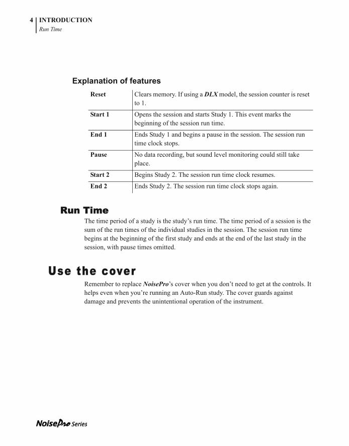
Explanation of features
Run TimeThe time period of a study is the study’s run time. The time period of a session is the sum of the run times of the individual studies in the session. The session run time begins at the beginning of the first study and ends at the end of the last study in the session, with pause times omitted.
Use the coverRemember to replace NoisePro’s cover when you don’t need to get at the controls. It helps even when you’re running an Auto-Run study. The cover guards against damage and prevents the unintentional operation of the instrument.
Reset Clears memory. If using a DLX model, the session counter is reset to 1.
Start 1 Opens the session and starts Study 1. This event marks the beginning of the session run time.
End 1 Ends Study 1 and begins a pause in the session. The session run time clock stops.
Pause No data recording, but sound level monitoring could still take place.
Start 2 Begins Study 2. The session run time clock resumes.
End 2 Ends Study 2. The session run time clock stops again.
053-379, Rev E053-379, Rev D
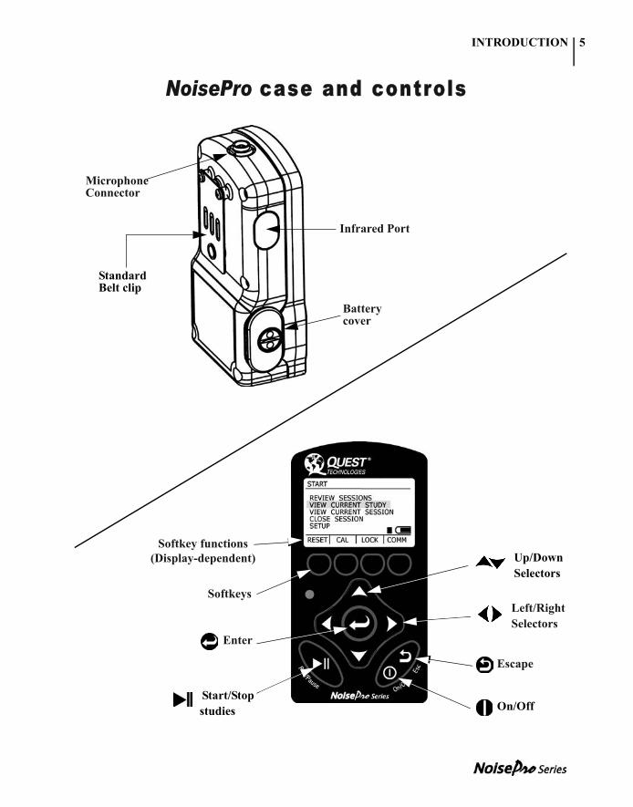
NoisePro case and controls
Left/Right Selectors
Escape
Softkeys
Up/Down Selectors
On/Off
Enter
Start/Stop studies
Softkey functions(Display-dependent)
Microphone Connector
Infrared Port
Battery cover
Standard Belt clip
INTRODUCTION 5

053-379, Rev E
INTRODUCTION
This page intentionally left blank
053-379, Rev D
6
053-379, Rev E
CHAPTER
053-379, Rev D
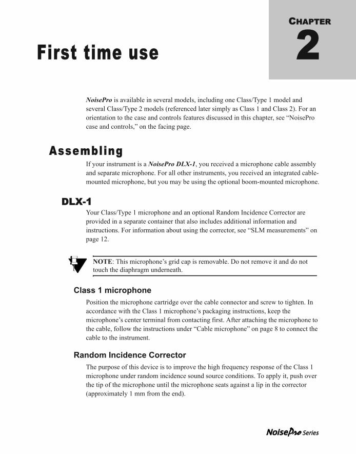
First time use 2NoisePro is available in several models, including one Class/Type 1 model and several Class/Type 2 models (referenced later simply as Class 1 and Class 2). For an orientation to the case and controls features discussed in this chapter, see “NoisePro case and controls,” on the facing page.
AssemblingIf your instrument is a NoisePro DLX-1, you received a microphone cable assembly and separate microphone. For all other instruments, you received an integrated cable-mounted microphone, but you may be using the optional boom-mounted microphone.
DLX-1Your Class/Type 1 microphone and an optional Random Incidence Corrector are provided in a separate container that also includes additional information and instructions. For information about using the corrector, see “SLM measurements” on page 12.
Class 1 microphonePosition the microphone cartridge over the cable connector and screw to tighten. In accordance with the Class 1 microphone’s packaging instructions, keep the microphone’s center terminal from contacting first. After attaching the microphone to the cable, follow the instructions under “Cable microphone” on page 8 to connect the cable to the instrument.
Random Incidence CorrectorThe purpose of this device is to improve the high frequency response of the Class 1 microphone under random incidence sound source conditions. To apply it, push over the tip of the microphone until the microphone seats against a lip in the corrector (approximately 1 mm from the end).
NOTE: This microphone’s grid cap is removable. Do not remove it and do not touch the diaphragm underneath.
053-379, Rev E
8 FIRST TIME USEAll other NoisePro models
053-379, Rev D
Frequency response curves for the microphone without the corrector are given under “Class 1 microphone” on page 87. Response curves with the corrector attached are provided with the Class 1 microphone.
All other NoisePro models
Cable microphoneAttach by connecting the cable to the instrument.
➤ To install
1. Rotate the cable connector to align it properly with the Microphone Connector. There is only one way that it fits.
2. Push it straight in. The connectors automatically latch together.
➤ To remove
1. Grab the ring in the middle of the cable connector.
2. Pull it straight out. The ring slides to unlatch the connectors.
Boom microphoneThe boom microphone is an optional type 2 microphone assembly.
➤ To install
1. Line up the boom connector with the Microphone Connector. There is only one way that it fits.
2. Plug in the boom connector.
3. Screw to tighten by rotating the boom connector’s knurled ring clockwise.
➤ To remove
1. Unscrew to release the boom connector’s knurled ring.
2. Pull the boom connector straight out of the Microphone Connector.
NoisePro keysMany of the procedures in this manual identify keys by the images that appear on the keys of the NoisePro keypad, for example for the power On/Off key. See “NoisePro case and controls” on page 6 for the locations of these keys.
053-379, Rev E
FIRST TIME USEPowering on/off
9
053-379, Rev D
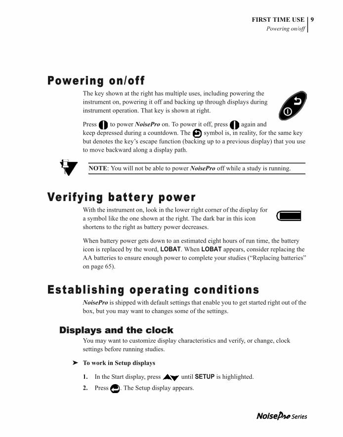
Powering on/of fThe key shown at the right has multiple uses, including powering the instrument on, powering it off and backing up through displays during instrument operation. That key is shown at right.
Press to power NoisePro on. To power it off, press again and keep depressed during a countdown. The symbol is, in reality, for the same key but denotes the key’s escape function (backing up to a previous display) that you use to move backward along a display path.
Verifying batter y powerWith the instrument on, look in the lower right corner of the display for a symbol like the one shown at the right. The dark bar in this icon shortens to the right as battery power decreases.
When battery power gets down to an estimated eight hours of run time, the battery icon is replaced by the word, LOBAT. When LOBAT appears, consider replacing the AA batteries to ensure enough power to complete your studies (“Replacing batteries” on page 65).
Establ ishing operating conditionsNoisePro is shipped with default settings that enable you to get started right out of the box, but you may want to changes some of the settings.
Displays and the clockYou may want to customize display characteristics and verify, or change, clock settings before running studies.
➤ To work in Setup displays
1. In the Start display, press until SETUP is highlighted.
2. Press . The Setup display appears.
NOTE: You will not be able to power NoisePro off while a study is running.
053-379, Rev E
FIRST TIME USESelecting logging options (DLX models only)
10
053-379, Rev D
3. Press to make your selection.
• Select TIME-DATE to set the clock.
• Select DISPLAY to control backlighting and pick descriptors.
4. For details on working in these and other setup displays, see “Setup display” on page 19.
5. When finished changing settings in any Setup display, press to escape to the previous display (more than once to keep backing up to previous displays).
Selecting logging options (DLX models only)In the DLX, you can choose logging parameters such as what gets logged and at what rate. See “Logging” on page 26 to learn about these procedures.
Choosing dosimeter setupsAll NoisePro models operate with multiple dosimeters at once, and each dosimeter can be assigned a setup from among the nine setups available. For information about these setups, including how to view them, change them and assign them to the dosimeters, see Chapter 4, “Configuring dosimeters.”
CalibratingIt’s wise to calibrate both before and after each study. The instrument will display pre-calibration and post-calibration information for your field review plus store it with the data for later review and analysis (Chapter 2, “Calibrations,”).
053-379, Rev E
FIRST TIME USEPreparing to measure
11
Preparing to measureReset session memory, attach the windscreen and mount the microphone and case in accordance with your purposes.
Reset operationA Reset removes all data from session memory, so make sure you no longer need that stored data before resetting.
You must be in the Start display to perform a Reset. If in any other display, complete whatever task you’re doing in that display and press one or more times to get back to the Start display. In the Start display, press the RESET softkey and hold until told in the display that all studies have been cleared.
Attach the windscreenUse the NoisePro windscreen for all measurements. A windscreen reduces errors due to wind turbulence and helps prevent microphone damage. After calibrating, push the windscreen over the tip of the microphone. It stretches for a snug fit.
Microphone positioningYou can use NoisePro for both dosimetry (personal monitoring) and sound level meter (SLM) measurements, but microphone positioning should be different for these two conditions.
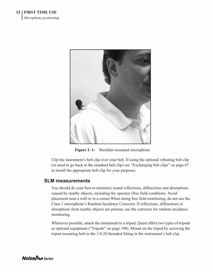
DosimetryClip the microphone to your shirt or collar (Figure 2–1) as high on the shoulder as possible and away from the neck. If the noise seems to come from one direction, place it on the shoulder closest to the noise source. During monitoring, keep clothing from coming into contact with the windscreen to avoid erroneous noise artifacts. If you have the optional microphone clips, use them to keep the cable from disturbing the microphone position ((“Optional accessories” on page 100).
NOTE: To use the DLX-1 model for dosimetry, attach the Random Incidence Corrector furnished with the Class 1 microphone.
053-379, Rev E
FIRST TIME USEMicrophone positioning
12
053-379, Rev D
Figure 2–1: Shoulder-mounted microphone
Clip the instrument’s belt clip over your belt. If using the optional vibrating belt clip (or need to go back to the standard belt clip) see “Exchanging belt clips” on page 67 to install the appropriate belt clip for your purposes.
SLM measurementsYou should do your best to minimize sound reflections, diffractions and absorptions caused by nearby objects, including the operator (free field condition). Avoid placement near a wall or in a corner.When doing free field monitoring, do not use the Class 1 microphone’s Random Incidence Corrector. If reflections, diffractions or absorptions from nearby objects are present, use the corrector for random incidence monitoring.
Whenever possible, attach the instrument to a tripod. Quest offers two types of tripods as optional equipment (“Tripods” on page 100). Mount on the tripod by screwing the tripod mounting bolt to the 1/4-20 threaded fitting in the instrument’s belt clip.
053-379, Rev E
FIRST TIME USEMeasuring noise levels
13
053-379, Rev D
Orient the microphone depending upon whether you are doing free field or random incidence monitoring.
• Free field (DLX-1 only)~ Point the microphone directly at the sound source.
• Random incidence ~ Angle the microphone upward at approximately 70o with respect to the sound source. (Applicable to all Class 2 models and the Class 1 model with the Random Incidence Corrector applied.)
Measuring noise levelsOnce the instrument is on, you can start and stop studies with a single key. During or after a study, you can open the Results display to examine a wide variety of level, average and dose measurements obtained with multiple dosimeter setups.
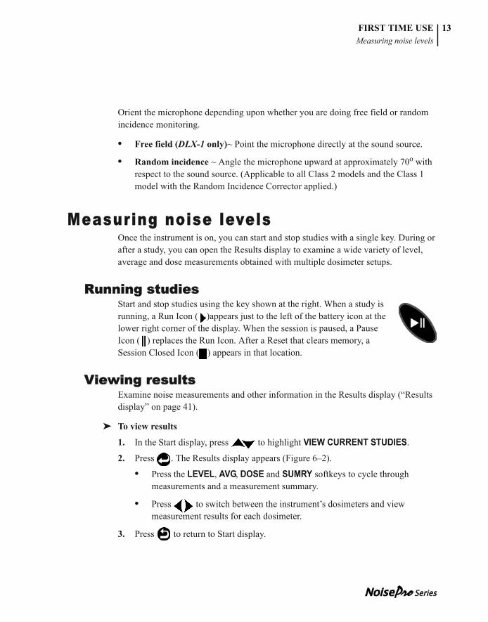
Running studiesStart and stop studies using the key shown at the right. When a study is running, a Run Icon ( )appears just to the left of the battery icon at the lower right corner of the display. When the session is paused, a Pause Icon ( ) replaces the Run Icon. After a Reset that clears memory, a Session Closed Icon ( ) appears in that location.
Viewing resultsExamine noise measurements and other information in the Results display (“Results display” on page 41).
➤ To view results
1. In the Start display, press to highlight VIEW CURRENT STUDIES.
2. Press . The Results display appears (Figure 6–2).
• Press the LEVEL, AVG, DOSE and SUMRY softkeys to cycle through measurements and a measurement summary.
• Press to switch between the instrument’s dosimeters and view measurement results for each dosimeter.
3. Press to return to Start display.
053-379, Rev E
FIRST TIME USEClosing sessions
14
053-379, Rev D
Closing sessions[DLX models only]. You can segregate studies into separate sessions by closing the current session. A new session will open when you start the next study.
➤ To close a session
1. In the Start display, press until CLOSE SESSION is highlighted.
2. Press . The session closes immediately.
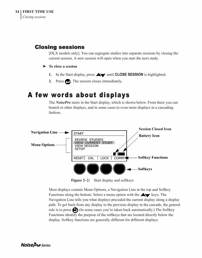
A few words about displaysThe NoisePro starts in the Start display, which is shown below. From there you can branch to other displays, and in some cases to even more displays in a cascading fashion.
Figure 2–2: Start display and softkeys
Most displays contain Menu Options, a Navigation Line at the top and Softkey Functions along the bottom. Select a menu option with the keys. The Navigation Line tells you what displays preceded the current display along a display path. To get back from any display to the previous display in the cascade, the general rule is to press (In some cases you’re taken back automatically.) The Softkey Functions identify the purpose of the softkeys that are located directly below the display. Softkey functions are generally different for different displays.
Session Closed Icon
Battery IconNavigation Line
Menu Options
Softkey Functions
Softkeys
053-379, Rev E
CHAPTER
053-379, Rev D
Calibrations 3Noise measurements are only as good as the calibration of the measuring instrument. To assure yourself that your NoisePro dosimeter is functioning within normal tolerance limits, return it to the factory periodically for a factory recalibration (“Factory service” on page 71).
This chapter explains how you can verify measurement calibration as part of your normal operating procedures.
Field calibratorThe Quest calibrator is a portable device emitting sound at a fixed frequency and sound level. For some calibrators, the signal frequency and sound level can be selected. For all calibrators, the indicated frequency and sound level is specified on the calibrator.
Calibrate the calibratorThe conformance of a field calibrator to its specifications should be periodically checked as well. To have a Quest calibrator checked, return it to a factory-authorized service center (“Factory service” on page 71).
Performing a f ield calibration
Preliminary steps • Stop the current study. You cannot calibrate while a study is running.
• If the windscreen is on the microphone, remove it.
• The instrument must be ON with the microphone connected to it.
• Check the instrument battery indicator. If LOBAT is showing, replace the instrument’s batteries before proceeding (“Replacing batteries” on page 65).
NOTE: Calibrators can be affected by changes in altitude and barometric pressure, and sometimes corrections are necessary. See your calibrator’s user manual.
053-379, Rev E
16 CALIBRATIONSAssemble
053-379, Rev D
• Check the calibrator battery indicator. If the LOBAT indicator is ON, see the calibrator’s user manual to replace the calibrator batteries before proceeding.
• If the calibrator has a selectable frequency setting, set it to 1000 Hz.
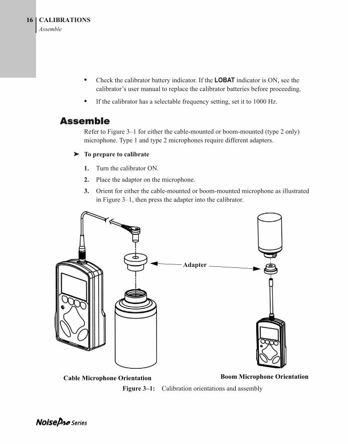
AssembleRefer to Figure 3–1 for either the cable-mounted or boom-mounted (type 2 only) microphone. Type 1 and type 2 microphones require different adapters.
➤ To prepare to calibrate
1. Turn the calibrator ON.
2. Place the adaptor on the microphone.
3. Orient for either the cable-mounted or boom-mounted microphone as illustrated in Figure 3–1, then press the adapter into the calibrator.
Figure 3–1: Calibration orientations and assembly
Adapter
Cable Microphone Orientation Boom Microphone Orientation
053-379, Rev E
CALIBRATIONSCalibration display
17
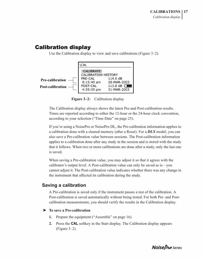
Calibration displayUse the Calibration display to view and save calibrations (Figure 3–2).
Figure 3–2: Calibration display
The Calibration display always shows the latest Pre-and Post-calibration results. Times are reported according to either the 12-hour or the 24-hour clock convention, according to your selection (“Time-Date” on page 25).
If you’re using a NoisePro or NoisePro DL, the Pre-calibration information applies to a calibration done with a cleared memory (after a Reset). For a DLX model, you can also save a Pre-calibration value between sessions. The Post-calibration information applies to a calibration done after any study in the session and is stored with the study that it follows. When two or more calibrations are done after a study, only the last one is saved.
When saving a Pre-calibration value, you may adjust it so that it agrees with the calibrator’s output level. A Post-calibration value can only be saved as is—you cannot adjust it. The Post-calibration value indicates whether there was any change in the instrument that affected its calibration during the study.
Saving a calibrationA Pre-calibration is saved only if the instrument passes a test of the calibration. A Post-calibration is saved automatically without being tested. For both Pre- and Post-calibration measurements, you should verify the results in the Calibration display.
➤ To save a Pre-calibration
1. Prepare the equipment (“Assemble” on page 16).
2. Press the CAL softkey in the Start display. The Calibration display appears (Figure 3–2).
Pre-calibration
Post-calibration
053-379, Rev E
18 CALIBRATIONS Calibration display
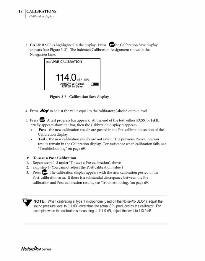
3. CALIBRATE is highlighted in the display. Press . Th e Calibration Save display appears (see Figure 3-3). Th e indented Calibration Assignment shows in the Navigation Line.
Figure 3-3: Calibration Save display
4. Press to adjust the value equal to the calibrator’s labeled output level.
5. Press . A test progress bar appears. At the end of the test, either PASS or FAIL briefl y appears above the bar, then the Calibration display reappears.
• Pass - the new calibration results are posted in the Pre-calibration section of the Calibration display.
• Fail - Th e new calibration results are not saved. Th e previous Pre-calibration results remain in the Calibration display. For assistance when calibration fails, see “Troubleshooting” on page 69.
To save a Post-Calibration 1. Repeat steps 1-3 under "To save a Pre-calibration”, above. 2. Skip step 4 (You cannot adjust the Post-calibration value.) 3. Press . Th e calibration display appears with the new calibration posted in the Post-calibration area. If there is a substantial discrepancy between the Pre- calibration and Post-calibration results, see "Troubleshooting, "on page 69.
NOTE: When calibrating a Type 1 microphone (used on the NoisePro DLX-1), adjust the sound pressure level to 0.1 dB lower than the actual SPL produced by the calibrator. For example, when the calibrator is measuring at 114.0 dB, adjust the level to 113.9 dB.
053-379, Rev E
CHAPTER
053-379, Rev D
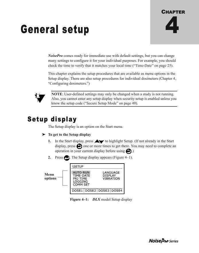
General setup 4NoisePro comes ready for immediate use with default settings, but you can change many settings to configure it for your individual purposes. For example, you should check the time to verify that it matches your local time (“Time-Date” on page 25).
This chapter explains the setup procedures that are available as menu options in the Setup display. There are also setup procedures for individual dosimeters (Chapter 4, “Configuring dosimeters.”)
Setup displayThe Setup display is an option on the Start menu.
➤ To get to the Setup display
1. In the Start display, press to highlight Setup. (If not already in the Start display, press one or more times to get there. You may need to complete an operation in your current display before using .)
2. Press . The Setup display appears (Figure 4–1).
Figure 4–1: DLX model Setup display
NOTE: User-defined settings may only be changed when a study is not running. Also, you cannot enter any setup display when security setup is enabled unless you know the setup code (“Secure Setup Mode” on page 49).
Menu options
053-379, Rev E
20 GENERAL SETUPAuto-Run
053-379, Rev D
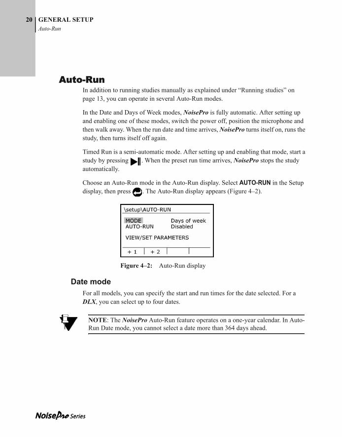
Auto-RunIn addition to running studies manually as explained under “Running studies” on page 13, you can operate in several Auto-Run modes.
In the Date and Days of Week modes, NoisePro is fully automatic. After setting up and enabling one of these modes, switch the power off, position the microphone and then walk away. When the run date and time arrives, NoisePro turns itself on, runs the study, then turns itself off again.
Timed Run is a semi-automatic mode. After setting up and enabling that mode, start a study by pressing . When the preset run time arrives, NoisePro stops the study automatically.
Choose an Auto-Run mode in the Auto-Run display. Select AUTO-RUN in the Setup display, then press . The Auto-Run display appears (Figure 4–2).
Figure 4–2: Auto-Run display
Date modeFor all models, you can specify the start and run times for the date selected. For a DLX, you can select up to four dates.
NOTE: The NoisePro Auto-Run feature operates on a one-year calendar. In Auto-Run Date mode, you cannot select a date more than 364 days ahead.
053-379, Rev E
GENERAL SETUPAuto-Run
21
053-379, Rev D
➤ To set in Date mode
1. If MODE is not selected in the Auto-Run display, cursor to highlight it (Figure 4–2).
2. Press once or twice until DATE appears on the right.
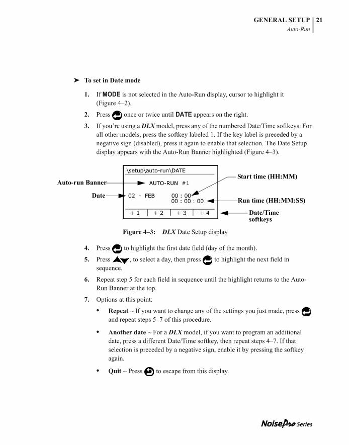
3. If you’re using a DLX model, press any of the numbered Date/Time softkeys. For all other models, press the softkey labeled 1. If the key label is preceded by a negative sign (disabled), press it again to enable that selection. The Date Setup display appears with the Auto-Run Banner highlighted (Figure 4–3).
Figure 4–3: DLX Date Setup display
4. Press to highlight the first date field (day of the month).
5. Press , to select a day, then press to highlight the next field in sequence.
6. Repeat step 5 for each field in sequence until the highlight returns to the Auto-Run Banner at the top.
7. Options at this point:
• Repeat ~ If you want to change any of the settings you just made, press and repeat steps 5–7 of this procedure.
• Another date ~ For a DLX model, if you want to program an additional date, press a different Date/Time softkey, then repeat steps 4–7. If that selection is preceded by a negative sign, enable it by pressing the softkey again.
• Quit ~ Press to escape from this display.
Date/Time softkeys
Start time (HH:MM)
Run time (HH:MM:SS)Date
Auto-run Banner
053-379, Rev E
GENERAL SETUPAuto-Run
22
053-379, Rev D
8. To activate this Auto-Run setup, see “Enable/disable Auto-Run” on page 24.
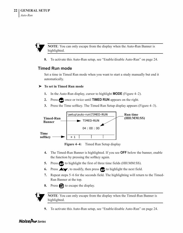
Timed Run modeSet a time in Timed Run mode when you want to start a study manually but end it automatically.
➤ To set in Timed Run mode
1. In the Auto-Run display, cursor to highlight MODE (Figure 4–2).
2. Press once or twice until TIMED RUN appears on the right.
3. Press the Time softkey. The Timed Run Setup display appears (Figure 4–3).
Figure 4–4: Timed Run Setup display
4. The Timed-Run Banner is highlighted. If you see OFF below the banner, enable the function by pressing the softkey again.
5. Press to highlight the first of three time fields (HH:MM:SS).
6. Press , to modify, then press to highlight the next field.
7. Repeat steps 5–6 for the seconds field. The highlighting will return to the Timed-Run Banner at the top.
8. Press to escape the display.
9. To activate this Auto-Run setup, see “Enable/disable Auto-Run” on page 24.
NOTE: You can only escape from the display when the Auto-Run Banner is highlighted.
NOTE: You can only escape from the display when the Timed-Run Banner is highlighted.
Run time (HH:MM:SS)Timed-Run
Banner
Time softkey
053-379, Rev E
GENERAL SETUPAuto-Run
23
053-379, Rev D
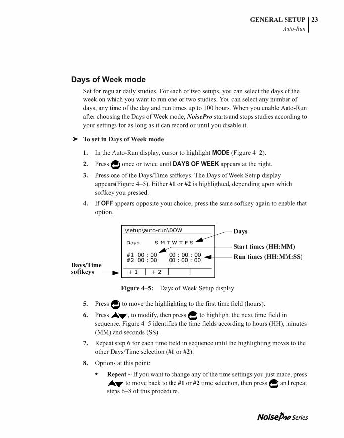
Days of Week modeSet for regular daily studies. For each of two setups, you can select the days of the week on which you want to run one or two studies. You can select any number of days, any time of the day and run times up to 100 hours. When you enable Auto-Run after choosing the Days of Week mode, NoisePro starts and stops studies according to your settings for as long as it can record or until you disable it.
➤ To set in Days of Week mode
1. In the Auto-Run display, cursor to highlight MODE (Figure 4–2).
2. Press once or twice until DAYS OF WEEK appears at the right.
3. Press one of the Days/Time softkeys. The Days of Week Setup display appears(Figure 4–5). Either #1 or #2 is highlighted, depending upon which softkey you pressed.
4. If OFF appears opposite your choice, press the same softkey again to enable that option.
Figure 4–5: Days of Week Setup display
5. Press to move the highlighting to the first time field (hours).
6. Press , to modify, then press to highlight the next time field in sequence. Figure 4–5 identifies the time fields according to hours (HH), minutes (MM) and seconds (SS).
7. Repeat step 6 for each time field in sequence until the highlighting moves to the other Days/Time selection (#1 or #2).
8. Options at this point:
• Repeat ~ If you want to change any of the time settings you just made, press to move back to the #1 or #2 time selection, then press and repeat
steps 6–8 of this procedure.
Start times (HH:MM)Run times (HH:MM:SS)
Days
Days/Time softkeys
053-379, Rev E
GENERAL SETUPAuto-Run
24
053-379, Rev D
• Another time ~If you want to program the second time, press and repeat steps 6–8 of this procedure. If the second Days/Time selection is disabled, enable it by pressing the softkey for that selection.
• Quit ~ Skip to step 13 below.
• Select days ~ Continue below.
9. If the highlighting is not on DAYS, press to move it there.
10. Press . The highlighting moves to a day choice.
11. Press to toggle the day, then press to move to the next day. If the letter is showing, that day is enabled. If a dash (–) is showing, the day is disabled.
12. Repeat step 11 for all the days of the week.
13. If done with the setup, press to escape the display.
14. To activate this Auto-Run setup, see “Enable/disable Auto-Run,” below.
Enable/disable Auto-RunAuto-Run is disabled by default. You must enable it to run studies according to the mode, date and time settings you previously selected. When you enable and power down, the time and date when the instrument will turn itself on will be displayed.
➤ To enable/disable Auto-Run
1. In the Auto-Run Setup display, cursor to highlight AUTO-RUN.
2. Press to toggle the setting to Enabled or Disabled.
3. Press to escape the display.
4. [Date or Days of Week mode only] Switch off NoisePro power. You must switch NoisePro off for these modes to operate.
NOTE: You can only escape the display when #1, #2 or DAYS is highlighted.
NOTE: If you set multiple auto-runs, make sure that you set the start time of each to occur no earlier than 2 minutes after the end of the previous auto-run.
053-379, Rev E
GENERAL SETUPTime-Date
25
053-379, Rev D
Time-DateSelect this display to change clock settings, for example to change the hour to adapt to a time zone or daylight savings time difference. In addition to setting the time and date, you can specify whether your display reads in the 12-hour or 24-hour format.
➤ To change settings
1. In the Time-Date display, press to select TIME, DISPLAY or DATE.
2. Press to advance the cursor into the data field.
3. Press to modify the setting.
4. Press to advance the cursor, either into the selection’s next data field or to a different selection.
5. Repeat all steps above to change other settings in this display.
6. Press to escape the display.
Prj TimeSet a Projected Time when you want to calculate dosages for a time that is different than the Run Time. This setting applies to all active dosimeters (global setting).
➤ To set Projected Time
1. In the Prj Time display, press to highlight the setting.
2. Press to select a new setting
3. Press to change it.
4. Press to escape the display.
NOTE: You can only escape the display when TIME, DISPLAY or DATE is highlighted.
053-379, Rev E
GENERAL SETUPLogging
26
053-379, Rev D
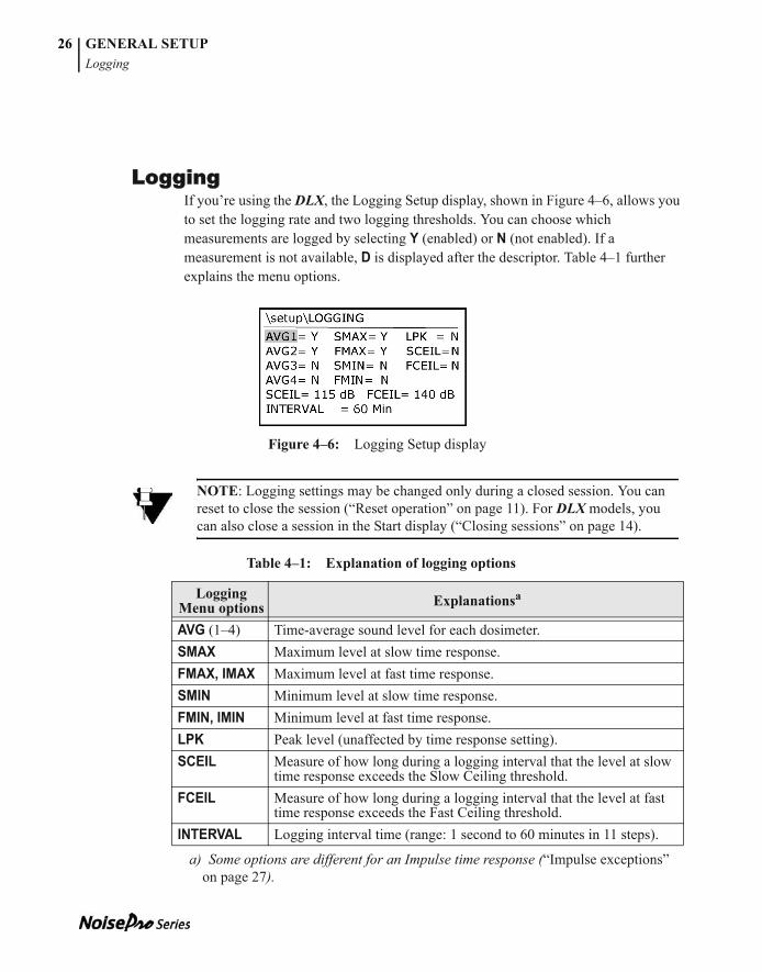
LoggingIf you’re using the DLX, the Logging Setup display, shown in Figure 4–6, allows you to set the logging rate and two logging thresholds. You can choose which measurements are logged by selecting Y (enabled) or N (not enabled). If a measurement is not available, D is displayed after the descriptor. Table 4–1 further explains the menu options.
Figure 4–6: Logging Setup display
Table 4–1: Explanation of logging options
NOTE: Logging settings may be changed only during a closed session. You can reset to close the session (“Reset operation” on page 11). For DLX models, you can also close a session in the Start display (“Closing sessions” on page 14).
Logging Menu options Explanationsa
a) Some options are different for an Impulse time response (“Impulse exceptions” on page 27).
AVG (1–4) Time-average sound level for each dosimeter.SMAX Maximum level at slow time response.FMAX, IMAX Maximum level at fast time response.SMIN Minimum level at slow time response.FMIN, IMIN Minimum level at fast time response.LPK Peak level (unaffected by time response setting).SCEIL Measure of how long during a logging interval that the level at slow
time response exceeds the Slow Ceiling threshold. FCEIL Measure of how long during a logging interval that the level at fast
time response exceeds the Fast Ceiling threshold.INTERVAL Logging interval time (range: 1 second to 60 minutes in 11 steps).
053-379, Rev E
GENERAL SETUPLogging
27
➤ To enable/disable logging
You can individually enable and disable time-average logging (AVG) for each dosimeter. You can also enable and disable logging for the maximum and minimum levels and for the ceiling times.
1. In the Logging Setup display, cursor to highlight the option.
2. Press to toggle the setting to Y or N.
3. Press to escape the display.
➤ To change a ceiling setting
1. In the Logging Setup display, cursor to highlight either SCEIL or FCEIL below the toggle options (they are followed by threshold settings).
2. Press to move the highlighting to the current ceiling setting.
3. Press to select a new setting
4. Press to change it.
5. Press to escape the display.
➤ To change the interval
This setting determines the logging rate (inverse of the interval).
1. In the Logging Setup display, cursor to highlight INTERVAL.
2. Press to move the highlighting to the current interval setting.
3. Press to select a new setting
4. Press to change it.
5. Press to escape the display.
Impulse exceptionsIf the time response is set to Impulse, the impulse measurements take the place of FMAX and FMIN. Also, some of the other measurements in the display are unavailable and are shown as disabled (D). This may include disabled dosimeters as well (“Assigning a setup to a dosimeter” on page 37).
NOTE: If D is shown for a dosimeter, that dosimeter is currently disabled (“Assigning a setup to a dosimeter” on page 37).
053-379, Rev E
GENERAL SETUPComm Set
28
053-379, Rev D
• The FMAX and FMIN descriptors are re-named IMAX and IMIN.
• SMAX and SMIN are disabled.
• FCEIL and SCEIL are disabled.
Comm SetThe Comm Set display allows you to choose between a wireless infrared or a cabled RS-232/USB interface for communication with external devices. However, because cabled communication is not supported at this time, you should always have the communications interface set to infrared.
When entering this display, INTERFACE is highlighted. If NoisePro is set properly, INFRARED is indicated in that line of the display. If set incorrectly, RS-232/USB is indicated, and you should change it.
➤ To choose the Infrared interface
1. With INTERFACE highlighted, press so that INFRARED is indicated. This key acts as a toggle between the two interfaces. The indicated communication rate will be 115200 baud; it cannot be changed.
2. Press to escape the display.
LanguageUse the Language display to choose from among five languages for display text. An asterisk appears next to the selected language.
➤ To change language
1. In the Language display, press to cursor to your choice
2. Press to make the change.
3. Press to escape the display.
053-379, Rev E
GENERAL SETUPDisplay
29
DisplayThe Display Menu provides display control and information functions.
ContrastThe contrast setting affects the intensity of the text in relation to the background. Higher numbers mean more contrast.
➤ To change contrast
1. In the Display Menu, press to highlight CONTRAST.
2. Press to modify the value.
3. Press to make the change.
4. Press to escape the display.
BacklightingThe power required to illuminate the display can be significantly greater than the power required for all other functions in the instrument. The less power you use for illumination purposes, the longer the replaceable batteries will last.
You can control backlighting with three options.
• Off ~ No backlighting under any conditions.
• Key ~ Backlighting only when a key is pressed.
• Auto ~ Backlighting only when ambient lighting is low.
➤ To control backlighting
1. In the Display Menu, press to highlight BACKLIGHT.
2. Press to toggle between the three options.
3. Press to escape the display.
053-379, Rev E
GENERAL SETUPVibrating belt clip
30
Measurement descriptorsThe Descriptors setting determines whether the Basic or IEC/ISO descriptors are used to report measurement results. For an explanation of these descriptors, see Appendix A , “Glossary.”
➤ To change Descriptors
1. In the Display Menu, press to highlight DESCRIPTORS.
2. Press to toggle the setting.
3. Press to escape the display.
View NoisePro informationThis display contains information about the instrument and about Quest.
➤ To view identifying information
1. In the Display Menu, press to highlight UNIT INFO.
2. Press to view the information.
3. Press to escape the display.
Vibrating belt clipThe optional vibrating belt clip can alert you with tactile feedback. For information about installing the vibrating belt clip, see “Exchanging belt clips” on page 67.
For all NoisePro models, the Time Weighted Average measurement of dosimeter 1 (DOSE1) serves as the reference. For the DLX, the logged LAVG may also serve as a separate reference. When a measurement exceeds the reference threshold, the belt clip is activated. For the TWA reference, the vibration lasts one second, then turns off and stays off. For the LAVG reference, the vibration alert lasts one second and may reactivate on each log interval.
NOTE: Only dosimeter 1 is used for vibration triggering. If you disable DOSE1 for any NoisePro model, vibration triggering is unavailable (“Assigning a setup to a dosimeter” on page 37). If you disable the logging of AVG1 for a DLX model, vibration triggering on LAVG is unavailable (“Logging” on page 26).

053-379, Rev E
GENERAL SETUPVibrating belt clip
31
Setting the trigger(s)The conditions for vibration triggering are established in the Vibration Setup display (Figure 4–7).
Figure 4–7: DL and DLX Vibration Setup display
➤ To change the vibration setup
1. [For the DL and DLX only] In the Vibration Setup display, press to highlight either TWA or LAVG.
2. Press to enter the threshold value field.
3. Press to change the setting.
4. Press to save the new value.
5. Press the ON or OFF softkey to enable or disable the trigger. The Status Indicator changes to reflect your choice.
6. [For the DL and DLX only] If you want to set the second trigger, repeat all steps above.
7. Press to escape the display.
Status Indicators
Threshold values

053-379, Rev E
GENERAL SETUPVibrating belt clip
32
This page intentionally left blank
053-379, Rev E
CHAPTER
Configuring dosimeters 5This chapter explains how to view and define the setup conditions under which the NoisePro dosimeters operate.
What is a dosimeter setup? The performance of a noise dosimeter is controlled by commonly recognized parameters that regulate how the dosimeter responds to time-varying noise signals. When reporting dosimetry results, the settings of several critical parameters must be reported at the same time so that meaningful comparisons can be made.
The collection of settings to the parameters that control a dosimeter is known as the dosimeter setup. NoisePro provides nine dosimeter setups, and any of them can be assigned to any dosimeter. Some of the setups have fixed settings that you cannot change; others allow you to make changes that conform to your own requirements. When you configure a dosimeter, you assign one of these nine setups to it.
Pre-defined setupsSix of the nine dosimeter setups are factory-defined, and five of those six cannot be changed by a user. These factory assignments conform to standards established for noise dosimetry in the United States and the European Union.
The five that are fixed comply with standards established by the Occupational Health and Safety Administration (OSHA), the Mine Safety and Health Administration (MSHA) and the American Conference of Governmental Industrial Hygienists (ACGIH). The sixth, labeled 200310EC, complies with minimum requirements under Directive 2003/10/EC of the European Union. The settings to the 200310EC parameters can be changed to accommodate preferences for more stringent standards in member EU countries.
These six pre-defined setups and their respective parametric settings are identified in Table 5–1. The tags, HC and PEL, refer to hearing conservation (HC) and Permissible Exposure Limit (PEL) levels that are defined in regulatory standards. See Appendix , “Glossary,” for information about these standards and levels.

053-379, Rev E
34 CONFIGURING DOSIMETERSUser-defined setups
Table 5–1: Parametric settings for pre-defined setups
User-defined setupsNoisePro has three additional setups that are labeled User 2, User 3 and User 4. You can change any of the settings in these setups and save the results. User setups can be assigned to a dosimeter and used just like pre-defined setups with one exception: you cannot make an assignment that contains settings that are incompatible with those in use by another dosimeter. When a conflict occurs, you have several options to resolve it (“Conflict resolution” on page 38).
Dosimeter setup displaysView, change and perform other tasks with dosimeter setups in the cascading group of displays shown for the DLX in Figure 5–1. If you are not using the DLX, some of the features will be absent.
• Dosimeters ~ The DOSE3 and DOSE4 softkey options are absent in other models. Only the DLX has four dosimeters.
• Setup display ~ The LOGGING option in the Setup display is absent for the other models.
Setup Response Exchange Rate
Criterion Level
Criterion Time Threshold Upper
LimitOSHA HC Slow 5 dB 90 dB 8 Hr 80 dB 115 dBOSHA PEL Slow 5 dB 90 dB 8 Hr 90 dB 115 dBMSHA HC Slow 5 dB 90 dB 8 Hr 80 dB 115 dBMSHA PEL Slow 5 dB 90 dB 8 Hr 90 dB 115 dBACGIH Slow 3 dB 85 dB 8 Hr 80 dB 115 dB200310EC Slow 3 dB 87 dB 8 Hr Off 115 dB
053-379, Rev E
CONFIGURING DOSIMETERSDosimeter Options display
35
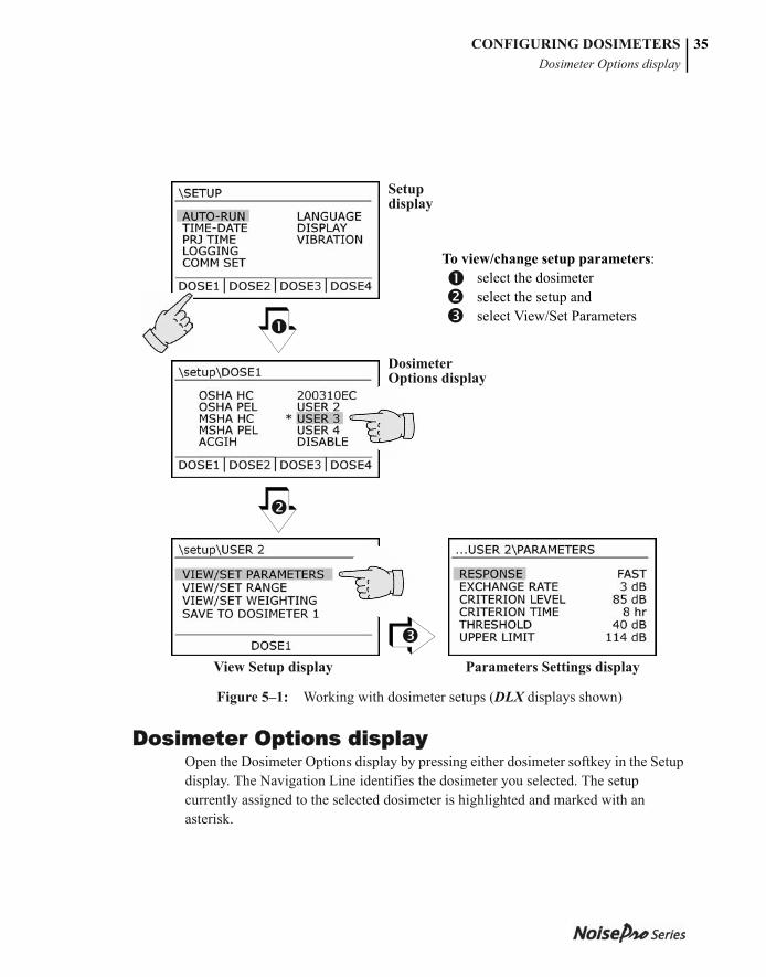
Figure 5–1: Working with dosimeter setups (DLX displays shown)
Dosimeter Options displayOpen the Dosimeter Options display by pressing either dosimeter softkey in the Setup display. The Navigation Line identifies the dosimeter you selected. The setup currently assigned to the selected dosimeter is highlighted and marked with an asterisk.
Parameters Settings displayView Setup display
To view/change setup parameters: select the dosimeter select the setup and select View/Set Parameters
Dosimeter Options display
Setup display
053-379, Rev E
CONFIGURING DOSIMETERSView Setup display
36
View Setup displayOpen the View Setup display by pressing a dosimeter softkey in the Dosimeter Options display. The selected dosimeter is identified at the bottom of the display. The setup currently assigned to the selected dosimeter is identified in the Navigation Line.
Parameter Settings displayView parameter settings or make changes to them in the Parameter Settings display. Open the Parameter Settings display for a setup selected in the View Setup display.
➤ To view setup parameters and settings
1. In the Dosimeter Options display, press to cursor to a setup option.
2. Press to complete the selection. The View Setup display opens.
3. Press to cursor to VIEW/SET PARAMETERS.
4. Press to complete the selection. The Parameter Settings display opens.
➤ To make changes in the Parameter Settings display
You can make changes to the 200310EC setup or to any of the three User setups. The changes are automatically saved to the selected setup as you go along.
1. Press to cursor to the parameter you want to change.
2. Press . The highlighting moves to the setting.
3. Press one or more times to select an option or change the value.
4. Press to return to the View Setup display.
NOTE: Parameter settings may be changed only during a closed session. You can reset to close the session (“Reset operation” on page 11). For DLX models, you can also close a session in the Start display (“Closing sessions” on page 14).
053-379, Rev E
CONFIGURING DOSIMETERSChanging range and weighting settings
37
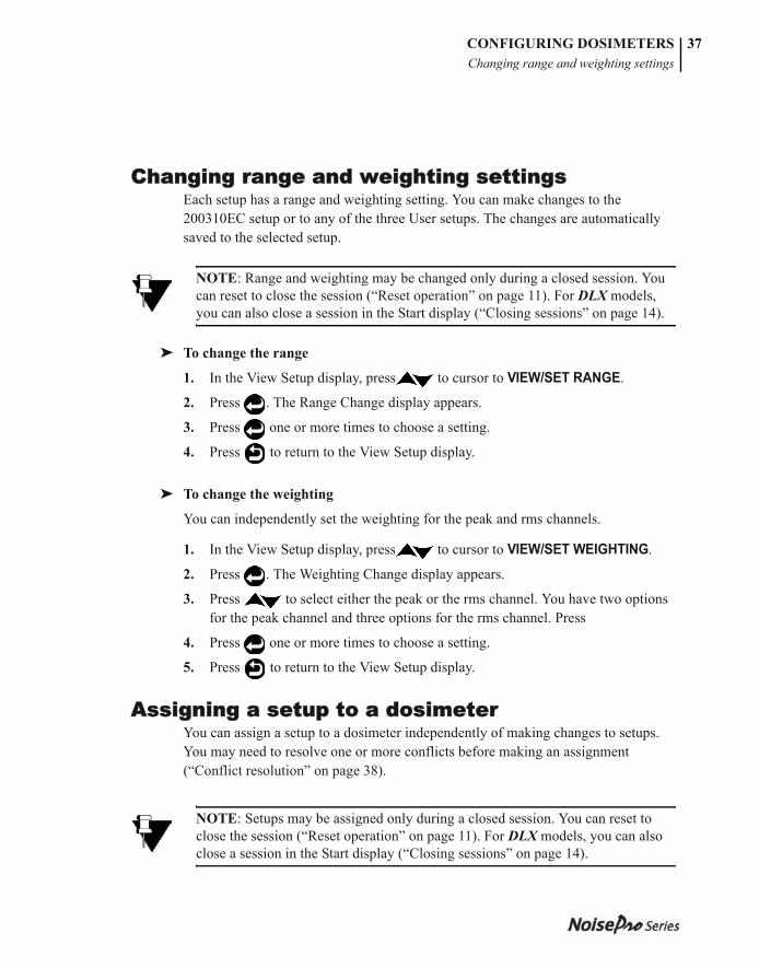
Changing range and weighting settingsEach setup has a range and weighting setting. You can make changes to the 200310EC setup or to any of the three User setups. The changes are automatically saved to the selected setup.
➤ To change the range
1. In the View Setup display, press to cursor to VIEW/SET RANGE.
2. Press . The Range Change display appears.
3. Press one or more times to choose a setting.
4. Press to return to the View Setup display.
➤ To change the weighting
You can independently set the weighting for the peak and rms channels.
1. In the View Setup display, press to cursor to VIEW/SET WEIGHTING.
2. Press . The Weighting Change display appears.
3. Press to select either the peak or the rms channel. You have two options for the peak channel and three options for the rms channel. Press
4. Press one or more times to choose a setting.
5. Press to return to the View Setup display.
Assigning a setup to a dosimeterYou can assign a setup to a dosimeter independently of making changes to setups. You may need to resolve one or more conflicts before making an assignment (“Conflict resolution” on page 38).
NOTE: Range and weighting may be changed only during a closed session. You can reset to close the session (“Reset operation” on page 11). For DLX models, you can also close a session in the Start display (“Closing sessions” on page 14).
NOTE: Setups may be assigned only during a closed session. You can reset to close the session (“Reset operation” on page 11). For DLX models, you can also close a session in the Start display (“Closing sessions” on page 14).
053-379, Rev E
CONFIGURING DOSIMETERSConflict resolution
38
➤ To assign a setup
This procedure assumes that you’re making the assignment independently of changing the setup. If you’re making the assignment as part of changing the setup you wish to assign, skip directly to step 3 below.
1. In the Setup display, press a softkey to select a dosimeter. (You can also select it in the Dosimeter Options display.)
2. In the Dosimeter Options display, press to cursor to a setup option.
3. In the View Setup display, press to cursor to SAVE TO DOSIMETER X, where X is the number of the dosimeter you selected in step 1.
4. Press . If the setup is allowable, the Dosimeter Options display appears. If not, a conflict resolution display appears. See below.
➤ To disable a dosimeter
You can disable a dosimeter by following the procedure above for assigning a setup, except in step #2, select DISABLED. When disabled, no data is processed or stored for that dosimeter. Enable a disabled dosimeter by assigning any available setup to it.
Conflict resolutionConflicts can exist for the following settings, but only for enabled dosimeters.
• Impulse time response ~ Cannot be mixed with Slow or Fast settings.
• Range ~ Must be the same for all dosimeters that are enabled.
• Weighting ~ Must be the same for all dosimeters that are enabled.
A conflict cannot exist between dosimeters if only one dosimeter is enabled. For that reason, one way to resolve a conflict is to intentionally disable all other dosimeters (“To disable a dosimeter,” above).
The other way to resolve a conflict is by means of the conflict resolution displays. A conflict resolution display appears whenever a conflict exists at the time of setup assignment. If more than one conflicting condition exists, the conflict resolution displays appear in sequence. Each conflict resolution display gives you two options.
• Save ~ Press to approve the new assignment. NoisePro resolves the conflict by disabling the other dosimeter(s).
• Escape ~ Press to exit the conflict resolution display with no change. You might consider changing setups, if possible, to remove the conflict.
053-379, Rev E
CHAPTER
Examining results 6This chapter explains how to examine measurement results in the NoisePro display as they are obtained or when retrieved from session memory. For information about examining results externally, see Chapter 8, “Communications.”
Selecting the sourceYou can view or review measurement results. Viewing means to look at the most current measurements. Reviewing means to look at measurements resulting from a completed study or, in the case of a DLX, resulting from a previous session.
Viewing current resultsIn the Start display, press to select either VIEW CURRENT STUDY or VIEW SESSION (will be marked VIEW CURRENT SESSION if you are using a DLX), then press . The Results display appears.
Current results means the most recent measurements by NoisePro. If you’re viewing while running a study, the results are being acquired and displayed as you watch. If you’re viewing a study during a pause, the final results from the last study performed are displayed.
NOTE: Except for the sound level measurement (first measurement in the Level category), all results are cleared in the display after a Reset. If you are using a DLX, results are also cleared when a session is closed

053-379, Rev E
40 EXAMINING RESULTSReviewing previous results
Reviewing previous resultsIn the Start display, press to select REVIEW STUDIES (will be marked REVIEW if you are using a DLX), then press . The Source Selection display appears (Figure 6–1).
Figure 6–1: Source Selection display
Reviewing resultsYou can review results for a previous study during a session pause. If you are using a DLX, you can review results for a previous session in memory if the current session is closed. To review current study or session results, see “Viewing current results” on page 39.
If you are using a DLX, select the session before selecting the study. If using one of the other NoisePro models, go directly to “To select the study,” below.
➤ To select the session (DLX only)
Opposite the word SESSION in the display are two numbers. The first number is the selected session. The second number tells you how many sessions are in memory (Reset sets this value to zero).
1. Cursor to highlight SESSION, then press . The highlighting moves to the selection field.
2. Press to change the selected session, then press to return.
3. If reviewing study results, continue with “To select the study,” below. If reviewing session results, press VIEW SESSION.
NoisePro and NoisePro DL displayNoisePro DLX display
053-379, Rev E
EXAMINING RESULTSResults display
41
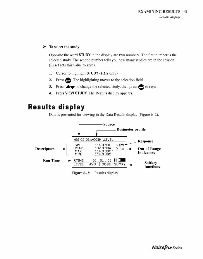
➤ To select the study
Opposite the word STUDY in the display are two numbers. The first number is the selected study. The second number tells you how many studies are in the session (Reset sets this value to zero).
1. Cursor to highlight STUDY (DLX only)
2. Press . The highlighting moves to the selection field.
3. Press to change the selected study, then press to return.
4. Press VIEW STUDY. The Results display appears.
Results displayData is presented for viewing in the Data Results display (Figure 6–2).
Figure 6–2: Results display
SourceDosimeter profile
Response
Descriptors
Run Time Softkey functions
Out-of-Range Indicators
053-379, Rev E
EXAMINING RESULTSDisplay characteristics
42
Display characteristics
What you see in the Data Results display depends upon a number of factors.
• Descriptor notation ~ Descriptors can be shown according to your choice of notation (“Measurement descriptors” on page 30).
• History ~ The mode of presentation is saved between visits. Each time you visit you return to the same presentation settings you had on your previous visit (or a default presentation on your first visit).
• Single/Group toggle ~ You can view smaller presentations of all measurements in a category at once or a larger presentation of one measurement at a time. Press to toggle between the single and grouped presentations.
Selecting with arrow keysUse the arrow keys to step through measurements, measurement categories and dosimeters.
Source Identifies the source of the information on display (“Specific source” on page 43.
Dosimeter profile
Name of the profile assigned to one of the active dosimeters which sets the conditions for these measurement results.
Descriptors Measurements made, separated into level, average and dose categories. For example, in Figure 6–2 the Level category contains the SPL, Peak, Max and Min descriptors.
Run time Run Time (RTIME) is given in hours, minutes and seconds (“Run Time” on page 4). You can determine whether a study is currently running by looking to see if RTIME is increasing or not.
Response Response setting for the selected dosimeter profile. To change this setting, see “Parameter Settings display” on page 36.
Out-of-Range Indicators
Normally nothing appears in this area. If you see either OL or UR there, this means an out-of-range condition occurred. See “Out-of-Range Indicators” on page 43 for an explanation.
Softkey functions
Use these to select the descriptor category or to show an interpretive summary (“Interpreted summaries” on page 44).
053-379, Rev E
EXAMINING RESULTSDisplay characteristics
43
• Press to step through measurements or groups of measurements, according to the current single/group toggle setting.
• Press to step through the dosimeter setups.
Specific sourceThe specific source for the results showing in the display depends upon which NoisePro model you’re using, whether you’re viewing or reviewing and whether the subject is a study or session.
• Viewing the current study ~ The word “Study” is shown, followed by the 2-digit number of the study. For example, \STUDY 03\ .... for study 3.
• Viewing the current session ~ The word “Session” is shown.
• Reviewing a study ~ The notation “SS” is shown followed by an identification of the session and the study written as XX:YY. For example, a review of study 3 of session 2 would be shown as 02:03. For non-DLX models, the session number is always “01.”
• Reviewing a session (DLX models) ~ The word “Session” is shown followed by the 2-digit number of the session. For example, \SESSION 02\ .... for session 2.
Out-of-Range IndicatorsThe Out-of-Range Indicators tell you when the input signal is above or below the linear operating range of the instrument.
• OL appears ~ The signal was too large and an overload occurred.
• UR appears ~ The signal was too small to be separated from instrument noise (“Noise Floor” on page 63).
If an overload occurs while you are running a study, the OL Indicator appears and stays there. If you are viewing a previous study or session results during which an overload occurred, the OL Indicator appears in the display. If you’re monitoring sound levels without recording, the OL Indicator appears only during an overload event, then goes away when the sound level returns to the normal operating range.
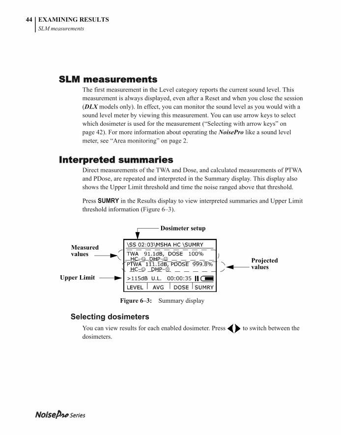
053-379, Rev E
EXAMINING RESULTSSLM measurements
44
SLM measurementsThe first measurement in the Level category reports the current sound level. This measurement is always displayed, even after a Reset and when you close the session (DLX models only). In effect, you can monitor the sound level as you would with a sound level meter by viewing this measurement. You can use arrow keys to select which dosimeter is used for the measurement (“Selecting with arrow keys” on page 42). For more information about operating the NoisePro like a sound level meter, see “Area monitoring” on page 2.
Interpreted summariesDirect measurements of the TWA and Dose, and calculated measurements of PTWA and PDose, are repeated and interpreted in the Summary display. This display also shows the Upper Limit threshold and time the noise ranged above that threshold.
Press SUMRY in the Results display to view interpreted summaries and Upper Limit threshold information (Figure 6–3).
Figure 6–3: Summary display
Selecting dosimetersYou can view results for each enabled dosimeter. Press to switch between the dosimeters.
Dosimeter setup
Measured values
Upper Limit
Projected values
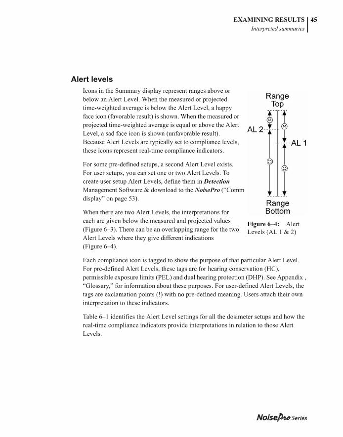
053-379, Rev E
EXAMINING RESULTSInterpreted summaries
45
Alert levelsIcons in the Summary display represent ranges above or below an Alert Level. When the measured or projected time-weighted average is below the Alert Level, a happy face icon (favorable result) is shown. When the measured or projected time-weighted average is equal or above the Alert Level, a sad face icon is shown (unfavorable result). Because Alert Levels are typically set to compliance levels, these icons represent real-time compliance indicators.
For some pre-defined setups, a second Alert Level exists. For user setups, you can set one or two Alert Levels. To create user setup Alert Levels, define them in Detection Management Software & download to the NoisePro (“Comm display” on page 53).
When there are two Alert Levels, the interpretations for each are given below the measured and projected values (Figure 6–3). There can be an overlapping range for the two Alert Levels where they give different indications (Figure 6–4).
Each compliance icon is tagged to show the purpose of that particular Alert Level. For pre-defined Alert Levels, these tags are for hearing conservation (HC), permissible exposure limits (PEL) and dual hearing protection (DHP). See Appendix , “Glossary,” for information about these purposes. For user-defined Alert Levels, the tags are exclamation points (!) with no pre-defined meaning. Users attach their own interpretation to these indicators.
Table 6–1 identifies the Alert Level settings for all the dosimeter setups and how the real-time compliance indicators provide interpretations in relation to those Alert Levels.
Figure 6–4: Alert Levels (AL 1 & 2)
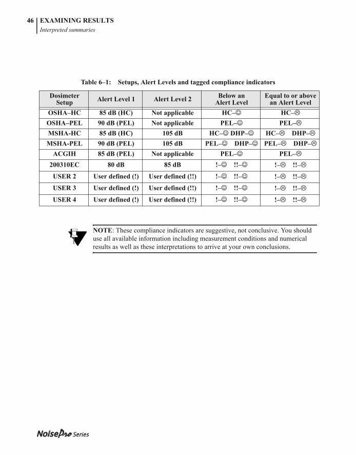
053-379, Rev E
EXAMINING RESULTSInterpreted summaries
46
Table 6–1: Setups, Alert Levels and tagged compliance indicators
Dosimeter Setup Alert Level 1 Alert Level 2 Below an
Alert LevelEqual to or above
an Alert LevelOSHA–HC 85 dB (HC) Not applicable HC– HC–OSHA–PEL 90 dB (PEL) Not applicable PEL– PEL–MSHA-HC 85 dB (HC) 105 dB HC– DHP– HC– DHP–MSHA-PEL 90 dB (PEL) 105 dB PEL– DHP– PEL– DHP–
ACGIH 85 dB (PEL) Not applicable PEL– PEL–200310EC 80 dB 85 dB !– !!– !– !!–
USER 2 User defined (!) User defined (!!) !– !!– !– !!–
USER 3 User defined (!) User defined (!!) !– !!– !– !!–
USER 4 User defined (!) User defined (!!) !– !!– !– !!–
NOTE: These compliance indicators are suggestive, not conclusive. You should use all available information including measurement conditions and numerical results as well as these interpretations to arrive at your own conclusions.
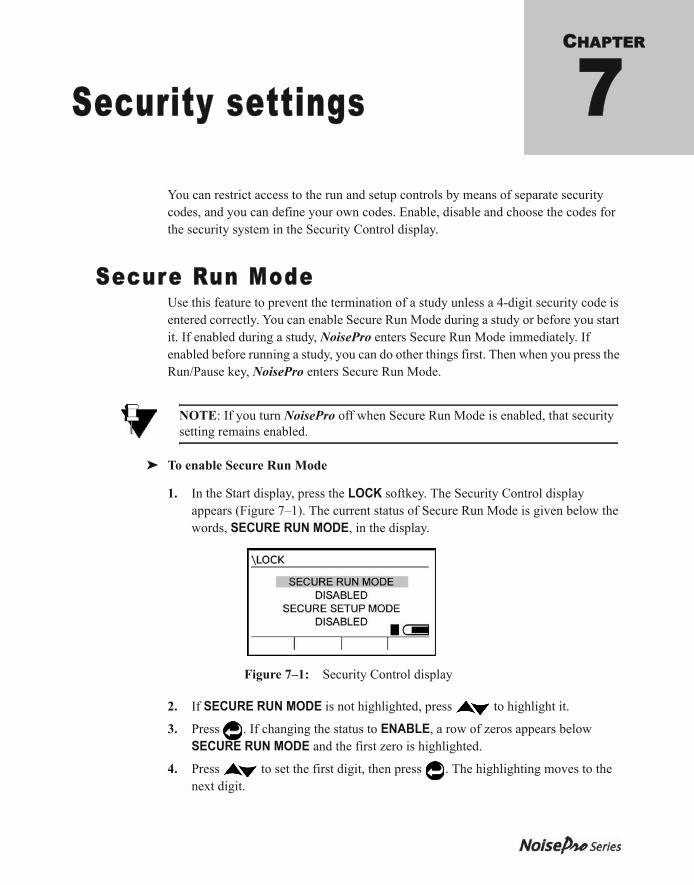
053-379, Rev E
CHAPTER
Security settings 7You can restrict access to the run and setup controls by means of separate security codes, and you can define your own codes. Enable, disable and choose the codes for the security system in the Security Control display.
Secure Run ModeUse this feature to prevent the termination of a study unless a 4-digit security code is entered correctly. You can enable Secure Run Mode during a study or before you start it. If enabled during a study, NoisePro enters Secure Run Mode immediately. If enabled before running a study, you can do other things first. Then when you press the Run/Pause key, NoisePro enters Secure Run Mode.
➤ To enable Secure Run Mode
1. In the Start display, press the LOCK softkey. The Security Control display appears (Figure 7–1). The current status of Secure Run Mode is given below the words, SECURE RUN MODE, in the display.
Figure 7–1: Security Control display
2. If SECURE RUN MODE is not highlighted, press to highlight it.
3. Press . If changing the status to ENABLE, a row of zeros appears below SECURE RUN MODE and the first zero is highlighted.
4. Press to set the first digit, then press . The highlighting moves to the next digit.
NOTE: If you turn NoisePro off when Secure Run Mode is enabled, that security setting remains enabled.
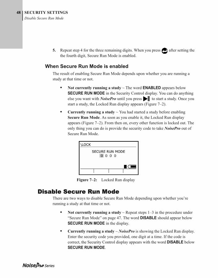
053-379, Rev E
48 SECURITY SETTINGSDisable Secure Run Mode
5. Repeat step 4 for the three remaining digits. When you press after setting the the fourth digit, Secure Run Mode is enabled.
When Secure Run Mode is enabledThe result of enabling Secure Run Mode depends upon whether you are running a study at that time or not.
• Not currently running a study ~ The word ENABLED appears below SECURE RUN MODE in the Security Control display. You can do anything else you want with NoisePro until you press to start a study. Once you start a study, the Locked Run display appears (Figure 7–2).
• Currently running a study ~ You had started a study before enabling Secure Run Mode. As soon as you enable it, the Locked Run display appears (Figure 7–2). From then on, every other function is locked out. The only thing you can do is provide the security code to take NoisePro out of Secure Run Mode.
Figure 7–2: Locked Run display
Disable Secure Run ModeThere are two ways to disable Secure Run Mode depending upon whether you’re running a study at that time or not.
• Not currently running a study ~ Repeat steps 1–3 in the procedure under “Secure Run Mode” on page 47. The word DISABLE should appear below SECURE RUN MODE in the display.
• Currently running a study ~ NoisePro is showing the Locked Run display. Enter the security code you provided, one digit at a time. If the code is correct, the Security Control display appears with the word DISABLE below SECURE RUN MODE.
053-379, Rev E
SECURITY SETTINGSSecure Setup Mode
49
Secure Setup ModeUse this feature to prevent changes to any NoisePro settings. When enabled, an operator can do anything with NoisePro except change its settings.
➤ To enable Secure Setup Mode
1. In the Start display, press the LOCK softkey. The Security Control display appears (Figure 7–1).
2. Press to highlight SECURE SETUP MODE. If the mode is disabled, DISABLED appears below SECURE SETUP MODE.
3. Press . If disabled, a row of zeros appears in place of DISABLED, with the first zero highlighted.
4. Press to set the first digit, then press . The highlighting moves to the next digit.
5. Repeat step 4 for the three remaining digits. When you press for the fourth digit, NoisePro enters Secure Setup Mode. The row of digits is replaced by the word ENABLED.
Disable Secure Setup ModeRepeat steps 1–5 in the procedure given under “Secure Setup Mode,” above. If you entered the correct 4-digit code, the word DISABLED appears in place of the row of zeros in step 5.
FORGOT THE CODE? Enter the Recovery Code, 9157, which always works.
NOTE: If you turn NoisePro off when Secure Setup Mode is enabled, that security setting remains enabled.
FORGOT THE CODE? Enter Recovery Code, 9157, which always works.

053-379, Rev E
SECURITY SETTINGSDisable Secure Setup Mode
50
This page intentionally left blank
053-379, Rev E
CHAPTER
Communications 8NoisePro can communicate with a personal computer and with other NoisePro units via infrared transmission. This chapter explains the hardware setups and software operations needed to control and execute communications processes.
Purposes of communication
Using Detection Mangement Software Detection Management Software DMS is a software application that is used for a variety of
functions including the ability to display and manipulate the data after it is downloaded to the computer from the instrument. Additionally, DMS is used to download measurement data (also called session and studies) for advanced graphing, charting, and reporting and analysis.
Shuttling resultsYou can transfer session results, called shuttling, from any NoisePro unit to a NoisePro DLX model. When the transfer is done, the data is stored in sequence on the DLX receiving unit but left on the sending unit. By this means, you can monitor with single-session models, shuttle session results to a DLX for offline processing then clear session memory in the sending unit and begin a new session.
Generating reportsWith NoisePros, you can create reports using DMS or you can organize session data into a report using Microsoft® HyperTerminal. For information about HyperTerminal, see the system support information supplied with Windows.
Communicating with NoisePro & cable to softwareAn infrared cable (part no. 53-857 and standard with most kits) links the 9-pin RS-232C serial (COM) port of your PC to the NoisePro unit's infrared communications port. An optional Serial-to-USB Adapter (part no. 53-810) is also available to mate the 53-857 cable to the USB port of your computer instead of an RS-232C serial
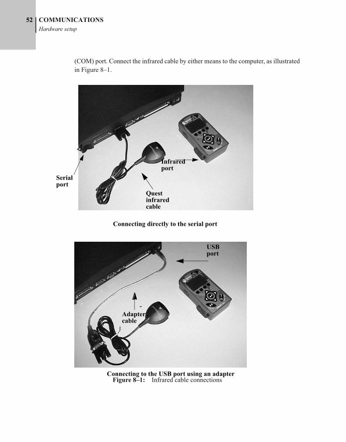
053-379, Rev E
52 COMMUNICATIONSHardware setup
(COM) port. Connect the infrared cable by either means to the computer, as illustrated in Figure 8–1.
Figure 8–1: Infrared cable connections
Connecting directly to the serial port
Connecting to the USB port using an adapter
USB port
Quest infrared cable
Infrared port
Adapter cable
Serial port
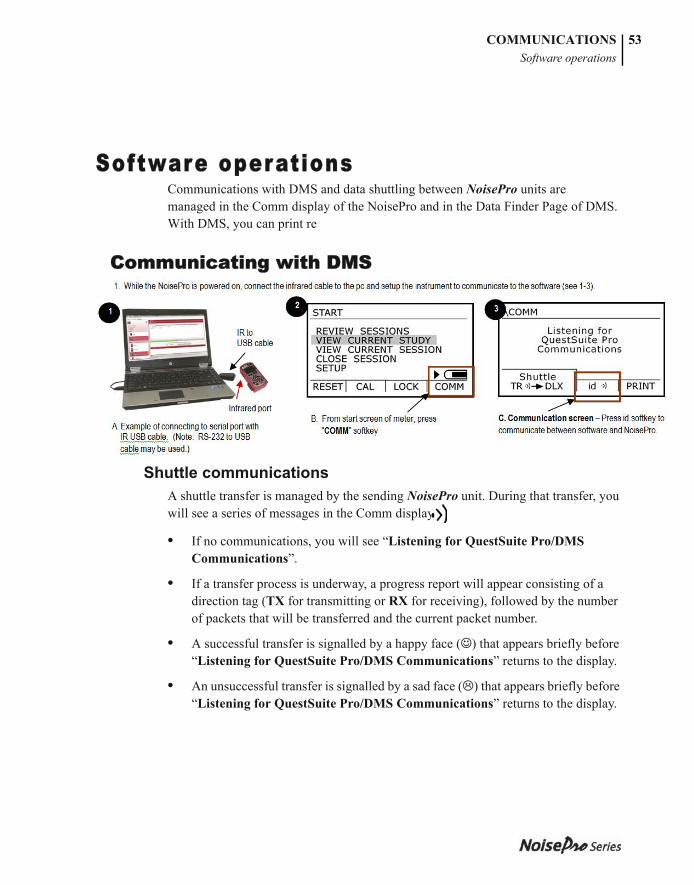
053-379, Rev E
COMMUNICATIONSSoftware operations
53
Software operationsCommunications with DMS and data shuttling between NoisePro units are managed in the Comm display of the NoisePro and in the Data Finder Page of DMS. With DMS, you can print re
Communicating with DMS In the Start display, press COMM to open the Comm display (Figure 8–2).
Figure 8–2: Comm display
Shuttle communicationsA shuttle transfer is managed by the sending NoisePro unit. During that transfer, you will see a series of messages in the Comm display.
• If no communications, you will see “Listening for QuestSuite Pro/DMS Communications”.
• If a transfer process is underway, a progress report will appear consisting of a direction tag (TX for transmitting or RX for receiving), followed by the number of packets that will be transferred and the current packet number.
• A successful transfer is signalled by a happy face ( ) that appears briefly before “Listening for QuestSuite Pro/DMS Communications” returns to the display.
• An unsuccessful transfer is signalled by a sad face ( ) that appears briefly before “Listening for QuestSuite Pro/DMS Communications” returns to the display.
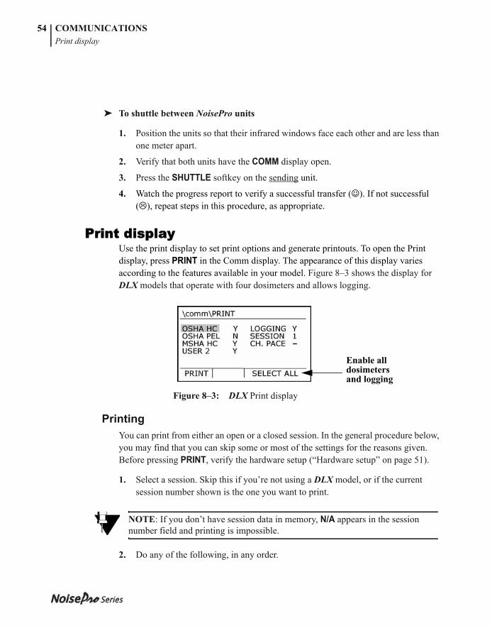
053-379, Rev E
COMMUNICATIONSPrint display
54
➤ To shuttle between NoisePro units
1. Position the units so that their infrared windows face each other and are less than one meter apart.
2. Verify that both units have the COMM display open.
3. Press the SHUTTLE softkey on the sending unit.
4. Watch the progress report to verify a successful transfer ( ). If not successful ( ), repeat steps in this procedure, as appropriate.
Print displayUse the print display to set print options and generate printouts. To open the Print display, press PRINT in the Comm display. The appearance of this display varies according to the features available in your model. Figure 8–3 shows the display for DLX models that operate with four dosimeters and allows logging.
Figure 8–3: DLX Print display
PrintingYou can print from either an open or a closed session. In the general procedure below, you may find that you can skip some or most of the settings for the reasons given. Before pressing PRINT, verify the hardware setup (“Hardware setup” on page 51).
1. Select a session. Skip this if you’re not using a DLX model, or if the current session number shown is the one you want to print.
2. Do any of the following, in any order.
NOTE: If you don’t have session data in memory, N/A appears in the session number field and printing is impossible.
Enable all dosimeters and logging
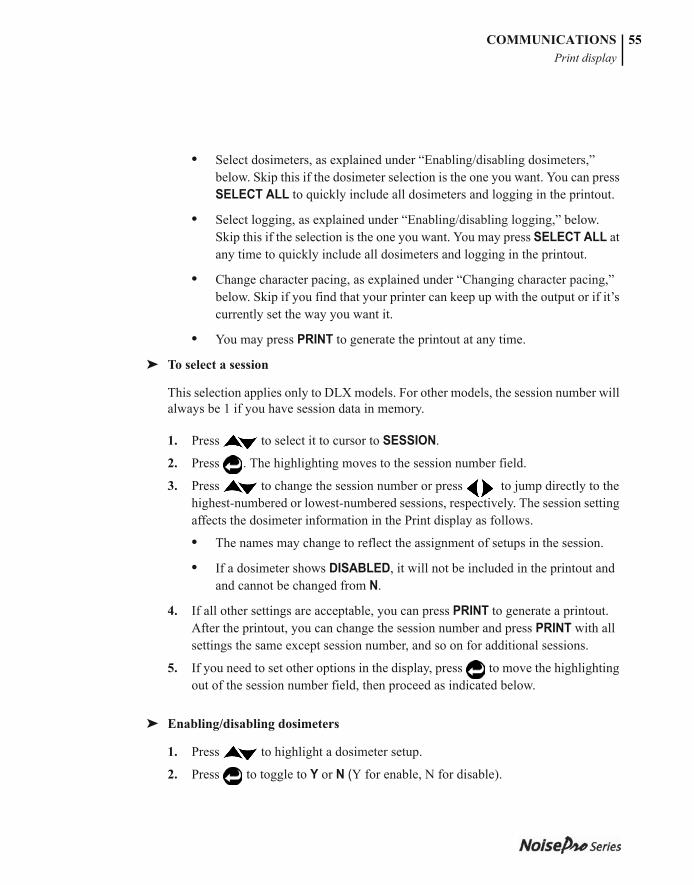
053-379, Rev E
COMMUNICATIONSPrint display
55
• Select dosimeters, as explained under “Enabling/disabling dosimeters,” below. Skip this if the dosimeter selection is the one you want. You can press SELECT ALL to quickly include all dosimeters and logging in the printout.
• Select logging, as explained under “Enabling/disabling logging,” below. Skip this if the selection is the one you want. You may press SELECT ALL at any time to quickly include all dosimeters and logging in the printout.
• Change character pacing, as explained under “Changing character pacing,” below. Skip if you find that your printer can keep up with the output or if it’s currently set the way you want it.
• You may press PRINT to generate the printout at any time.
➤ To select a session
This selection applies only to DLX models. For other models, the session number will always be 1 if you have session data in memory.
1. Press to select it to cursor to SESSION.
2. Press . The highlighting moves to the session number field.
3. Press to change the session number or press to jump directly to the highest-numbered or lowest-numbered sessions, respectively. The session setting affects the dosimeter information in the Print display as follows.
• The names may change to reflect the assignment of setups in the session.
• If a dosimeter shows DISABLED, it will not be included in the printout and and cannot be changed from N.
4. If all other settings are acceptable, you can press PRINT to generate a printout. After the printout, you can change the session number and press PRINT with all settings the same except session number, and so on for additional sessions.
5. If you need to set other options in the display, press to move the highlighting out of the session number field, then proceed as indicated below.
➤ Enabling/disabling dosimeters
1. Press to highlight a dosimeter setup.
2. Press to toggle to Y or N (Y for enable, N for disable).
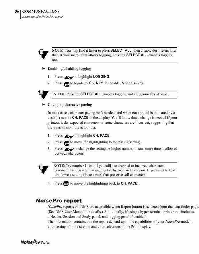
053-379, Rev E
COMMUNICATIONSAnatomy of a NoisePro report
56
➤ Enabling/disabling logging
1. Press to highlight LOGGING.
2. Press to toggle to Y or N (Y for enable, N for disable).
➤ Changing character pacing
In most cases, character pacing isn’t needed, and when not applied is indicated by a dash (–) next to CH. PACE in the display. You’ll know that a change is needed if your printout lacks expected characters or some characters are incorrect, suggesting that the transmission rate is too fast.
1. Press to highlight CH. PACE.
2. Press to move the highlighting to the pacing setting.
3. Press to change the setting. A higher number means more time is allowed between characters.
4. Press to move the highlighting back to CH. PACE.
NoisePro reportNoisePro reports via DMS are accessible when Report button is selected from the data finder page.(See DMS User Manual for details.) Additionally, if using a hyper terminal printer this includesa Header, Session and Study panel, and logging panel if enabled.The information contained in the report depend upon the capabilities of your NoisePro model, your settings for the session and your selections in the Print display.
NOTE: You may find it faster to press SELECT ALL, then disable dosimeters after that. If your instrument allows logging, pressing SELECT ALL enables logging too.
NOTE: Pressing SELECT ALL enables logging and all dosimeters at once.
NOTE: Try number 1 first. If you still see dropped or incorrect characters, increment the character pacing number by five, and try again. Experiment to find
the lowest setting (fastest rate) that preserves all characters.
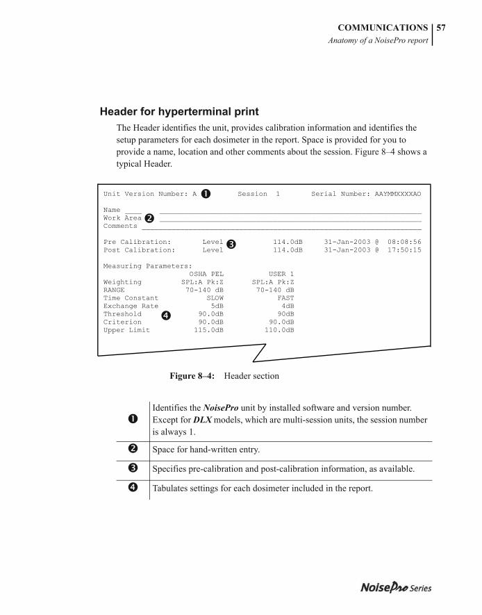
053-379, Rev E
COMMUNICATIONSAnatomy of a NoisePro report
57
Header for hyperterminal printThe Header identifies the unit, provides calibration information and identifies the setup parameters for each dosimeter in the report. Space is provided for you to provide a name, location and other comments about the session. Figure 8–4 shows a typical Header.
Figure 8–4: Header section
Identifies the NoisePro unit by installed software and version number. Except for DLX models, which are multi-session units, the session number is always 1.
Space for hand-written entry.
Specifies pre-calibration and post-calibration information, as available.
Tabulates settings for each dosimeter included in the report.
Unit Version Number: A.132 Session 1 Serial Number: AAYMMXXXXAO Name ______________________________________________________________________ Work Area _________________________________________________________________ Comments __________________________________________________________________ Pre Calibration: Level 114.0dB 31-Jan-2003 @ 08:08:56 Post Calibration: Level 114.0dB 31-Jan-2003 @ 17:50:15 Measuring Parameters: OSHA PEL USER 1 Weighting SPL:A Pk:Z SPL:A Pk:Z RANGE 70-140 dB 70-140 dB Time Constant SLOW FAST Exchange Rate 5dB 4dB Threshold 90.0dB 90dB Criterion 90.0dB 90.0dB Upper Limit 115.0dB 110.0dB
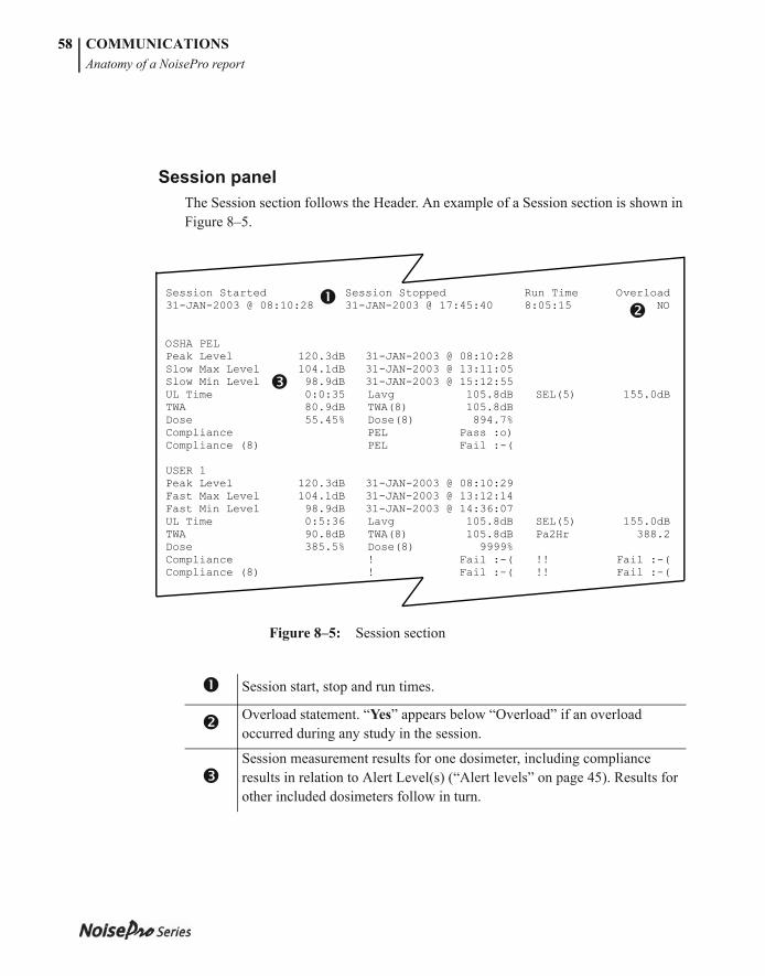
053-379, Rev E
COMMUNICATIONSAnatomy of a NoisePro report
58
Session panelThe Session section follows the Header. An example of a Session section is shown in Figure 8–5.
Figure 8–5: Session section
Session start, stop and run times.
Overload statement. “Yes” appears below “Overload” if an overload occurred during any study in the session.
Session measurement results for one dosimeter, including compliance results in relation to Alert Level(s) (“Alert levels” on page 45). Results for other included dosimeters follow in turn.
Session Started Session Stopped Run Time Overload 31-JAN-2003 @ 08:10:28 31-JAN-2003 @ 17:45:40 8:05:15 NO OSHA PEL Peak Level 120.3dB 31-JAN-2003 @ 08:10:28 Slow Max Level 104.1dB 31-JAN-2003 @ 13:11:05 Slow Min Level 98.9dB 31-JAN-2003 @ 15:12:55 UL Time 0:0:35 Lavg 105.8dB SEL(5) 155.0dB TWA 80.9dB TWA(8) 105.8dB Dose 55.45% Dose(8) 894.7% Compliance PEL Pass :o) Compliance (8) PEL Fail :-( USER 1 Peak Level 120.3dB 31-JAN-2003 @ 08:10:29 Fast Max Level 104.1dB 31-JAN-2003 @ 13:12:14 Fast Min Level 98.9dB 31-JAN-2003 @ 14:36:07 UL Time 0:5:36 Lavg 105.8dB SEL(5) 155.0dB TWA 90.8dB TWA(8) 105.8dB Pa2Hr 388.2 Dose 385.5% Dose(8) 9999% Compliance ! Fail :-( !! Fail :-( Compliance (8) ! Fail :-( !! Fail :-(

053-379, Rev E
COMMUNICATIONSAnatomy of a NoisePro report
59
Study panelStudy sections follow the Session section, in order, for as many studies as were performed in the session. An example of a Study section is shown in Figure 8–6.
Figure 8–6: Study section
Identifies this study as the second one in the session (Session:Study). Space is provided here for you to enter your comments about the study.
Post calibration results for this study.
Study start, stop and run times, followed by an overload statement. “Yes” appears if an overload occurred during this study.Study measurement results for one dosimeter, including compliance results in relation to Alert Level(s) (“Alert levels” on page 45). Results for other included dosimeters follow in turn.
STUDY (1:2) _______________________________________________________________ ___________________________________________________________________________ Post Calibration: Level 114.0dB 31-Jan-2003 @ 17:50:15 Study Started Study Stopped Run Time Overload 31-JAN-2003 @ 13:10:22 31-JAN-2003 @ 17:45:40 04:35:18 NO OSHA PEL Peak Level 108.0 dB 31-JAN-2003 @ 13:11:05 Slow Max Level 104.1dB 31-JAN-2003 @ 13:11:05 Slow Min Level 98.9dB 31-JAN-2003 @ 15:12:55 UL Time 0:0:05 UL Time 0:0:0 Lavg 105.8dB SEL(5) 155.0dB TWA 80.8dB TWA(8) 105.8dB Dose 30.5% Dose(8) 9999% Compliance PEL Pass :o) Compliance (8) PEL Fail :-( USER 1 Peak Level 130.3dB 31-JAN-2003 @ 08:10:29 Fast Max Level 104.1dB 31-JAN-2003 @ 13:12:14 Fast Min Level 98.9dB 31-JAN-2003 @ 14:36:07 UL Time 0:2:05 Lavg 108.8dB SEL(5) 165.0dB TWA 90.8dB TWA(8) 108.8dB Dose 385.5% Dose(8) 9999% Compliance ! Fail :-( !! Fail :-( Compliance (8) ! Fail :-( !! Fail :-(
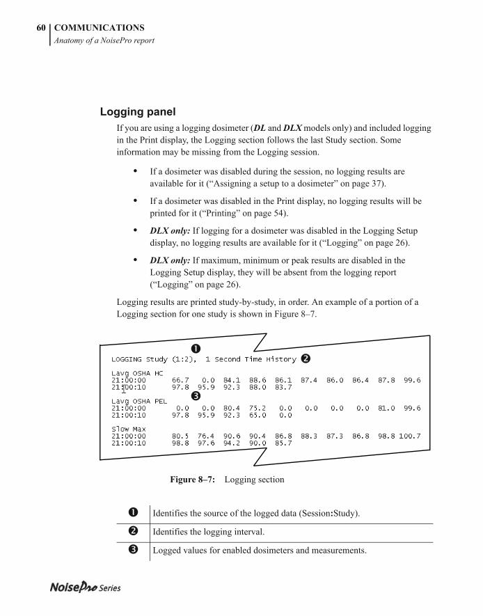
053-379, Rev E
COMMUNICATIONSAnatomy of a NoisePro report
60
Logging panelIf you are using a logging dosimeter (DL and DLX models only) and included logging in the Print display, the Logging section follows the last Study section. Some information may be missing from the Logging session.
• If a dosimeter was disabled during the session, no logging results are available for it (“Assigning a setup to a dosimeter” on page 37).
• If a dosimeter was disabled in the Print display, no logging results will be printed for it (“Printing” on page 54).
• DLX only: If logging for a dosimeter was disabled in the Logging Setup display, no logging results are available for it (“Logging” on page 26).
• DLX only: If maximum, minimum or peak results are disabled in the Logging Setup display, they will be absent from the logging report (“Logging” on page 26).
Logging results are printed study-by-study, in order. An example of a portion of a Logging section for one study is shown in Figure 8–7.
Figure 8–7: Logging section
Identifies the source of the logged data (Session:Study).
Identifies the logging interval.
Logged values for enabled dosimeters and measurements.
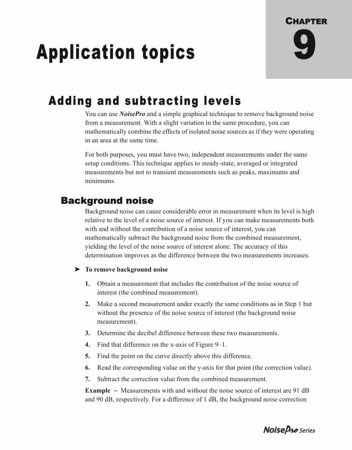
053-379, Rev E
CHAPTER
Application topics 9Adding and subtracting levels
You can use NoisePro and a simple graphical technique to remove background noise from a measurement. With a slight variation in the same procedure, you can mathematically combine the effects of isolated noise sources as if they were operating in an area at the same time.
For both purposes, you must have two, independent measurements under the same setup conditions. This technique applies to steady-state, averaged or integrated measurements but not to transient measurements such as peaks, maximums and minimums.
Background noiseBackground noise can cause considerable error in measurement when its level is high relative to the level of a noise source of interest. If you can make measurements both with and without the contribution of a noise source of interest, you can mathematically subtract the background noise from the combined measurement, yielding the level of the noise source of interest alone. The accuracy of this determination improves as the difference between the two measurements increases.
➤ To remove background noise
1. Obtain a measurement that includes the contribution of the noise source of interest (the combined measurement).
2. Make a second measurement under exactly the same conditions as in Step 1 but without the presence of the noise source of interest (the background noise measurement).
3. Determine the decibel difference between these two measurements.
4. Find that difference on the x-axis of Figure 9–1.
5. Find the point on the curve directly above this difference.
6. Read the corresponding value on the y-axis for that point (the correction value).
7. Subtract the correction value from the combined measurement.
Example ~ Measurements with and without the noise source of interest are 91 dB and 90 dB, respectively. For a difference of 1 dB, the background noise correction
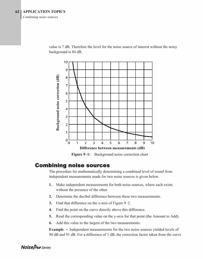
053-379, Rev E
62 APPLICATION TOPICSCombining noise sources
value is 7 dB. Therefore the level for the noise source of interest without the noisy background is 84 dB..
Figure 9–1: Background noise correction chart
Combining noise sourcesThe procedure for mathematically determining a combined level of sound from independent measurements made for two noise sources is given below.
1. Make independent measurements for both noise sources, where each exists without the presence of the other.
2. Determine the decibel difference between these two measurements.
3. Find that difference on the x-axis of Figure 9–2.
4. Find the point on the curve directly above this difference.
5. Read the corresponding value on the y-axis for that point (the Amount to Add).
6. Add this value to the largest of the two measurements.
Example ~ Independent measurements for the two noise sources yielded levels of 90 dB and 91 dB. For a difference of 1 dB, the correction factor taken from the curve
Difference between measurements (dB)
Bac
kgro
und
nois
e co
rrec
tion
(dB
)
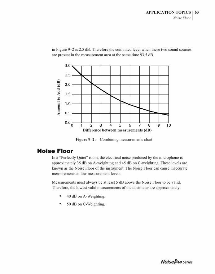
053-379, Rev E
APPLICATION TOPICSNoise Floor
63
in Figure 9–2 is 2.5 dB. Therefore the combined level when these two sound sources are present in the measurement area at the same time 93.5 dB.
Figure 9–2: Combining measurements chart
Noise FloorIn a “Perfectly Quiet” room, the electrical noise produced by the microphone is approximately 35 dB on A-weighting and 45 dB on C-weighting. These levels are known as the Noise Floor of the instrument. The Noise Floor can cause inaccurate measurements at low measurement levels.
Measurements must always be at least 5 dB above the Noise Floor to be valid. Therefore, the lowest valid measurements of the dosimeter are approximately:
• 40 dB on A-Weighting.
• 50 dB on C-Weighting.
Difference between measurements (dB)
Am
ount
to A
dd (d
B)

053-379, Rev E
APPLICATION TOPICSNoise Floor
64
This page intentionally left blank

053-379, Rev E
CHAPTER
Maintenance 10When replacing the main NoisePro batteries, make sure to use approved batteries and to heed battery replacement warnings given below.
Approved batteriesUse only approved AA batteries from the following list.
• Eveready E91 Energizer “Max”
• Eveready EN91 Energizer “Industrial”
• GE/Sanyo “Power Cell”
Replacing batteriesReplace the batteries when the word, LOBAT, appears in place of the battery icon. Stored data and user settings are unaffected by battery replacement.
WARNING: To prevent ignition of flammable or combustible atmospheres, no user serviceable parts inside. Repair should be done by authorized service personnel only.
WARNING: To reduce the risk of explosion, do not mix used batteries with unused batteries or mix batteries from different manufacturers.
WARNING: To reduce the risk of ignition of a flammable or explosive atmosphere, batteries must be changed only in a location known to be non-hazardous.
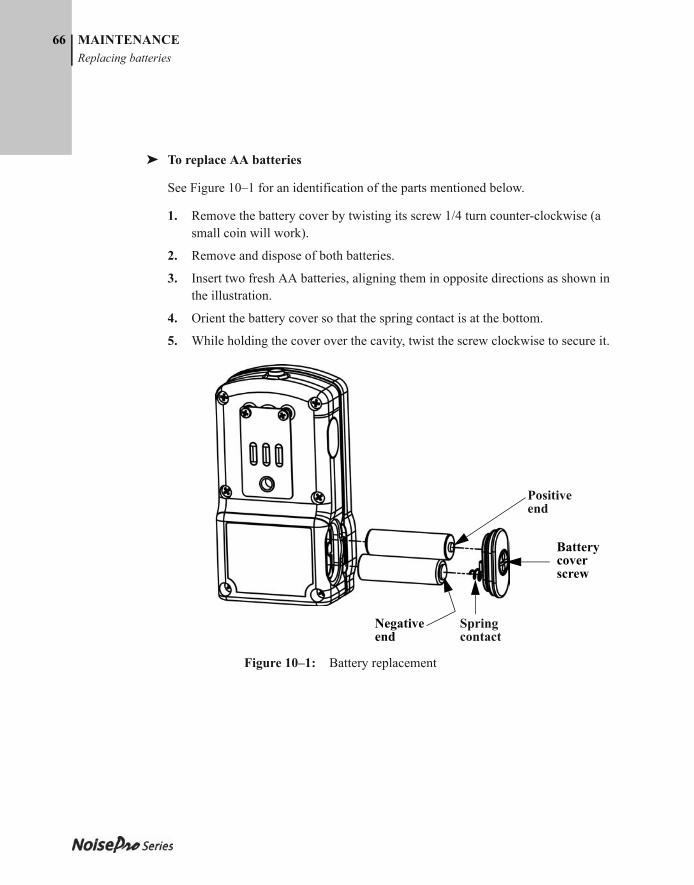
053-379, Rev E
66 MAINTENANCEReplacing batteries
➤ To replace AA batteries
See Figure 10–1 for an identification of the parts mentioned below.
1. Remove the battery cover by twisting its screw 1/4 turn counter-clockwise (a small coin will work).
2. Remove and dispose of both batteries.
3. Insert two fresh AA batteries, aligning them in opposite directions as shown in the illustration.
4. Orient the battery cover so that the spring contact is at the bottom.
5. While holding the cover over the cavity, twist the screw clockwise to secure it.
Figure 10–1: Battery replacement
Positive end
Spring contact
Battery cover screw
Negative end
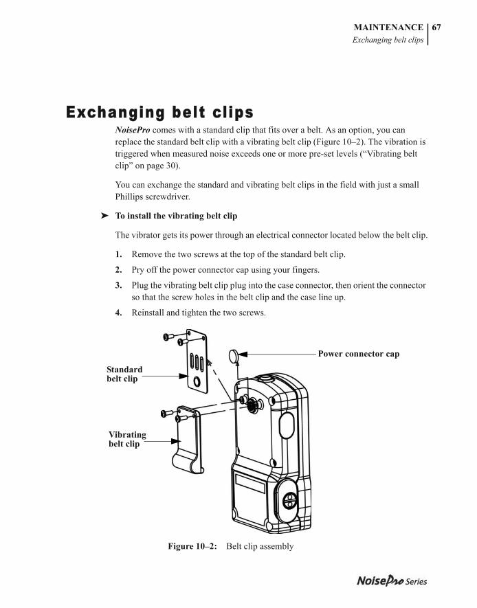
053-379, Rev E
MAINTENANCEExchanging belt clips
67
Exchanging belt cl ipsNoisePro comes with a standard clip that fits over a belt. As an option, you can replace the standard belt clip with a vibrating belt clip (Figure 10–2). The vibration is triggered when measured noise exceeds one or more pre-set levels (“Vibrating belt clip” on page 30).
You can exchange the standard and vibrating belt clips in the field with just a small Phillips screwdriver.
➤ To install the vibrating belt clip
The vibrator gets its power through an electrical connector located below the belt clip.
1. Remove the two screws at the top of the standard belt clip.
2. Pry off the power connector cap using your fingers.
3. Plug the vibrating belt clip plug into the case connector, then orient the connector so that the screw holes in the belt clip and the case line up.
4. Reinstall and tighten the two screws.
Figure 10–2: Belt clip assembly
Standard belt clip
Vibrating belt clip
Power connector cap

053-379, Rev E
MAINTENANCEExchanging belt clips
68
This page intentionally left blank
053-379, Rev E
CHAPTER
Technical support 11Troubleshooting
Blank display• Unit lost power. Replace batteries with fresh ones.
• If fresh batteries do not resolve the problem, return the unit for service.
General calibration problems• Verify that calibrator LOBAT indicator isn’t on. LOBAT means that the calibrator
battery must be replaced.
• For a multiple frequency calibrator, verify that the frequency is set to 1000 Hz.
• Make sure you can hear a tone from the calibrator.
• If you cannot determine the reason for the problem, contact Quest Technical Services for assistance.
Pre-calibration value not saved• See “General calibration problems,” above.
• Repeat the calibration, verifying that your adjusted setting in the Calibration display matches the posted output of the calibrator.
• If the repeated attempt fails and you have another microphone (for example a boom-mounted microphone), exchange the microphones and try again.
Post-calibration discrepancy• See “General calibration problems,” above.
• If you have a different calibrator with the same output level, use it to repeat the post-calibration.
053-379, Rev E
70 TECHNICAL SUPPORTUnit is erratic
Unit is erratic• Verify the microphone if you have another one. (The microphone or preamp
could be intermittent).
• If the microphone seems okay, return the unit for service.
Clock settings lost• If the settings are lost while replacing the AA batteries, the internal Lithium
battery may be weak and need replacement. Return the unit to the factory for service. See “Factory service,” below.
Belt clip vibrator not working• Verify that at least one trigger is enabled. See “Vibrating belt clip” on page 30.
• Verify that DOS1 is enabled.
• For the DXL, and triggering on LAVG, verify that AVG1 is enabled for logging (“Logging” on page 26).
Belt clip vibrator won’t turn off• The sound level may be continuously exceeding a trigger threshold. You can take
action based on the significance of the trigger level, disable the trigger or reset the trigger to a higher level (“Vibrating belt clip” on page 30).
Communications not working• Make sure that the communications interface is set to INFRARED (“Comm Set”
on page 28).
Mic errorMicrophone was removed while a study is running. The study is interrupted while NoisePro is paused.
Battery error (PFR restore)The battery was removed while a study is running. NoisePro attempted a Power Fail Restore operation (PFR) to restore the previous run conditions.
053-379, Rev E
Factory ServiceNoisePro’s and 3M Quest fi eld calibrators should be examined regularly by the factory. 3M Quest recommends annual service.
As part of the factory service, 3M Quest checks the condition of your instrument’s internal battery. Th is battery is needed to preserve the clock settings when the AA cells are replaced. It must be factory serviced.
If you have questions about the NoisePro’s operation or need to have it serviced, contact 3M Quest Technologies as explained below.
• Customer Service: (262) 567-9157 or Toll Free: 800-245-0779• Fax: 1 (262) 567-4047. Offi ce hours are 8:00 a.m. to 5:00 p.m. United States Central.• E-mail: [email protected] • Internet: www.3M.com/detection
Th is contact information as well as the NoisePro’s model and serial number and other identifying information is located on the NoisePro’s Setup, Display, and Unit Information Screen.
TECHNICAL SUPPORT 71 Factory Service

053-379, Rev E
TECHNICAL SUPPORTFactory service
72
This page intentionally left blank
053-379, Rev E
APPENDIX
Glossary ABasic Descriptors
Descriptors are the terms used for measurements. NoisePro provides two types of descriptor systems: Basic and IEC/ISO. Basic descriptors are the most common measurement terms used for noise dosimetry in the United States. For information about IEC/ISO Descriptors, including a table that identifies descriptor differences, see “IEC/ISO Descriptors,”below.
Criterion Level (CL)The Criterion Level is the maximum allowable exposure to accumulated noise. It gives the conditions that result in a 100% doses. The Criterion Level is typically set by a regulating agency, such as OSHA, and is not usually applicable for community noise monitoring.
Examples: OSHA mandates the Criterion Level (maximum allowable accumulated noise exposure) to be 90 dB for 8 hours. For an 8 hour sample, an average level (LAVG) of 90 dB will result in 100% dose.
For the OSHA HEARING CONSERVATION AMENDMENT, the “action level” is 85 dB for 8 hours. This would result in a 50% dose reading. Note that the Criterion Level has not changed. (If the Criterion Level is changed to 85 dB then an 8 hour average of 85 dB would result in 100% dose.)
Criterion TimeThe time over which the Criterion Level is established, generally eight hours.
Decibel (dB) Engineers frequently are faced with the need to compare things. One way to do that is to form a ratio of their quantities. For example, a meter is 100 times the size of a centimeter—the ratio is dimensionless. Engineers commonly determine differences in power using a special unit called a decibel. The decibel is calculated as the logarithm of the power ratio. Logarithms are used because they compress the range of very large ratios so that they’re easier to display together.
053-379, Rev E
74 GLOSSARYDose
DoseRelated to the Criterion Level, a dose reading of 100% is the maximum allowable exposure to accumulated noise. For OSHA, 100% dose occurs for an average sound level of 90 dB over an 8 hour period (or any equivalent exposure). By using a TWA reading rather than the average sound level, the time period is no longer explicitly needed. A TWA of 90 dB is the equivalent of 100% dose. The dose will double (halve) every time the TWA increases (decreases) by the Exchange Rate.
Example: OSHA uses an Exchange Rate of 5 dB. Suppose the TWA is 100 dB. The dose would double for each 5 dB increase over the Criterion Level of 90 dB. The resulting dose is therefore 400%. If the TWA was instead equal to 80 dB then the dose would halve for each 5 dB below the Criterion Level. The resulting dose would be 25%.
When taking noise samples less that the full workday, dose is an easy number to work with because it is linear with respect to time.
Example: If a 0.5 hour sample results in 9% dose and the workday is 7.5 hours long, then the dose for the full workday would be a 135% dose (7.5 / 0.5 x 9%). This is computed making the assumption that the sampled noise will continue at the same levels for the full 7.5 hour workday.
Exceedence LevelsAn Exceedence Level is the level exceeded by the measured noise level for an identified fraction of time. Exceedence Levels may be calculated for many time fractions.
Example: An L40 equal to 73 dB would mean that for 40% of the run time, the decibel level was higher than 73 dB.
Exchange Rate (ER)Also known as the Doubling Rate, this figure refers to how the sound energy is averaged over time. Using the decibel scale, every time the sound energy doubles, the measured level increases by 3 dB. This is the 3 dB Exchange Rate that most of the world uses. For every increase of 3 dB in the time weighted average, the measured dose would double.
053-379, Rev E
GLOSSARYHearing Conservation (HC)
75
Some organizations such as OSHA in the U.S. have argued that the human ear self compensates for changing noise levels and they felt that the 3 dB Exchange Rate should be changed to more closely match the response of the human ear. OSHA currently uses a 5 dB Exchange Rate which would mean that the reported dose would double with every 5 dB increase in the time weighted average. The Exchange Rate affects the integrated reading LAVG, Dose, and TWA but does not affect the instantaneous sound level.
Hearing Conservation (HC)A sound level established as a standard by a consensus group or a regulatory agency to be used in a hearing conservation program. The Occupational Safety and Health Administration (OSHA) and Mine Safety and Health Administration (MSHA) provide regulatory standards for hearing conservation programs. In addition, the American Conference of Governmental Industrial Hygienists (ACGIH) provide industrial standards for hearing conservation programs.
Hertz (Hz) Unit of vibration frequency, numerically equal to cycles per second.
IEC/ISO DescriptorsDescriptors are the terms used for measurements. NoisePro provides two types of descriptor systems: Basic and IEC/ISO. The IEC/ISO system is commonly used for noise dosimetry in the European Union.
Basic noise descriptors are strictly abbreviations for the measurements. In the IEC/ISO noise descriptor system, shorter abbreviations are used but are augmented by codings that identify the settings for time and frequency parameters.
Table A–1 lists Basic and corresponding IEC/ISO descriptors and explains the meanings of the codings in the IEC/ISO descriptors.
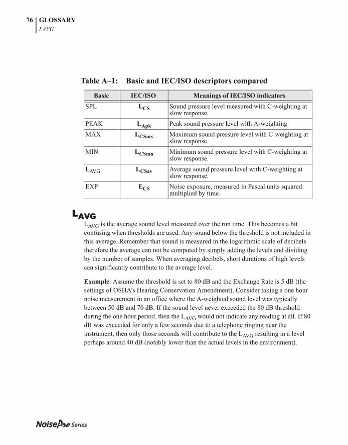
053-379, Rev E
GLOSSARYLAVG
76
Table A–1: Basic and IEC/ISO descriptors compared
LAVGLAVG is the average sound level measured over the run time. This becomes a bit confusing when thresholds are used. Any sound below the threshold is not included in this average. Remember that sound is measured in the logarithmic scale of decibels therefore the average can not be computed by simply adding the levels and dividing by the number of samples. When averaging decibels, short durations of high levels can significantly contribute to the average level.
Example: Assume the threshold is set to 80 dB and the Exchange Rate is 5 dB (the settings of OSHA’s Hearing Conservation Amendment). Consider taking a one hour noise measurement in an office where the A-weighted sound level was typically between 50 dB and 70 dB. If the sound level never exceeded the 80 dB threshold during the one hour period, then the LAVG would not indicate any reading at all. If 80 dB was exceeded for only a few seconds due to a telephone ringing near the instrument, then only those seconds will contribute to the LAVG resulting in a level perhaps around 40 dB (notably lower than the actual levels in the environment).
Basic IEC/ISO Meanings of IEC/ISO indicatorsSPL LCS Sound pressure level measured with C-weighting at
slow response.PEAK LApk Peak sound pressure level with A-weightingMAX LCSmx Maximum sound pressure level with C-weighting at
slow response.MIN LCSmn Minimum sound pressure level with C-weighting at
slow response.LAVG LCSav Average sound pressure level with C-weighting at
slow response.EXP ECS Noise exposure, measured in Pascal units squared
multiplied by time.
053-379, Rev E
GLOSSARYLDN
77
LDNRepresenting the Day/Night sound level, this measurement is a 24-hour average sound level where 10 dB is added to all of the readings that occur between 10pm and 7am. This is primarily used in community noise regulations where there is a 10 dB “penalty” for night time noise. Typically LDN’s are measured using A weighting, a 3 dB Exchange Rate, and no Threshold.
LEP,dDaily personal noise exposure.
LEQThe true equivalent sound level measured over the run time. The term LEQ is functionally the same as LAVG except that it is only used when the Exchange Rate is set to 3 dB and the threshold is set to none.
Max LevelThe highest level sampled sound level during the instrument’s run time allowing for the response that the unit is set for (fast or slow).
Min LevelThe lowest level sampled sound level during the instrument’s run time allowing for the response that the unit is set for (fast or slow).
Peak LevelPeak is the highest instantaneous sound level that the microphone detects. Unlike the Max Level, the peak is detected independently of the slow or fast response that the unit is set for.
Example: The peak circuitry is very sensitive. Test this by simply blowing across the microphone. You will notice that the peak reading may be 120 dB or greater. When taking a long term noise sample (such as a typical 8-hour workday sample for Osha compliance), the peak level is often very high. Because brushing the microphone over a shirt collar or accidentally bumping it can cause such a high reading, the user must be careful of placing too much emphasis on the reading.
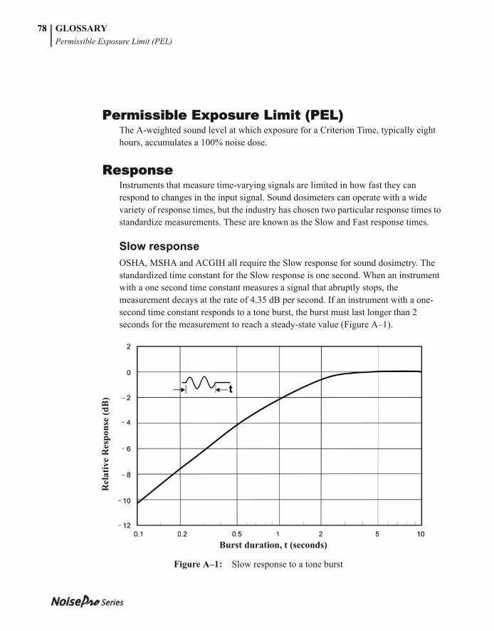
053-379, Rev E
GLOSSARYPermissible Exposure Limit (PEL)
78
Permissible Exposure Limit (PEL)The A-weighted sound level at which exposure for a Criterion Time, typically eight hours, accumulates a 100% noise dose.
ResponseInstruments that measure time-varying signals are limited in how fast they can respond to changes in the input signal. Sound dosimeters can operate with a wide variety of response times, but the industry has chosen two particular response times to standardize measurements. These are known as the Slow and Fast response times.
Slow responseOSHA, MSHA and ACGIH all require the Slow response for sound dosimetry. The standardized time constant for the Slow response is one second. When an instrument with a one second time constant measures a signal that abruptly stops, the measurement decays at the rate of 4.35 dB per second. If an instrument with a one-second time constant responds to a tone burst, the burst must last longer than 2 seconds for the measurement to reach a steady-state value (Figure A–1).
Figure A–1: Slow response to a tone burst
Burst duration, t (seconds)
Rel
ativ
e R
espo
nse
(dB
)
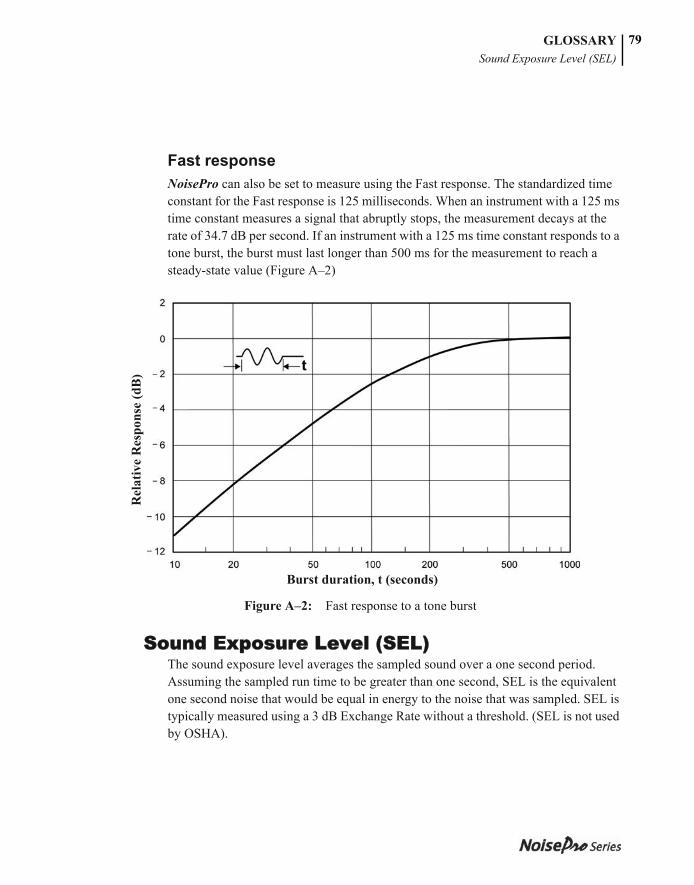
053-379, Rev E
GLOSSARYSound Exposure Level (SEL)
79
Fast responseNoisePro can also be set to measure using the Fast response. The standardized time constant for the Fast response is 125 milliseconds. When an instrument with a 125 ms time constant measures a signal that abruptly stops, the measurement decays at the rate of 34.7 dB per second. If an instrument with a 125 ms time constant responds to a tone burst, the burst must last longer than 500 ms for the measurement to reach a steady-state value (Figure A–2)
Figure A–2: Fast response to a tone burst
Sound Exposure Level (SEL)The sound exposure level averages the sampled sound over a one second period. Assuming the sampled run time to be greater than one second, SEL is the equivalent one second noise that would be equal in energy to the noise that was sampled. SEL is typically measured using a 3 dB Exchange Rate without a threshold. (SEL is not used by OSHA).
Burst duration, t (seconds)
Rel
ativ
e R
espo
nse
(dB
)
053-379, Rev E
GLOSSARYThreshold
80
Example: Suppose you wanted to measure in a location next to railroad tracks which also happened to be in the takeoff path of an airport. A train passes by taking 10 minutes with an average sound level of 82 dB. A jet passes overhead taking 45 seconds with an average level of 96 dB. Which of these events results in more sound energy? Answer: You can answer the question by comparing their SEL readings which compress each event into an equivalent one second occurrence. The SEL for the train is 109.7 dB; the SEL for the jet = 112.5 dB.
Threshold Also known as the Cut Off, the Threshold affects the LAVG, TWA, and Dose measurements. All sound below the Threshold is considered nonexisting noise for the averaging and integrating functions. The Threshold does not affect measurements in the sound level mode.
OSHA uses two different thresholds. The original Occupational Noise Exposure Standard (1971) used a 90 dB threshold and called for engineering controls to reduce the noise levels if the eight hour TWA was greater than 90 dB. The Hearing Conservation Amendment (1983) uses an 80 dB threshold and calls for a hearing conservation program to be put in place if the eight hour TWA exceeds 85 dB (50% dose). The Hearing Conservation Amendment is the more stringent of the two rulings and is what most US industrial users are concerned with.
Example: With an 80 dB threshold, suppose you placed a 79 dB calibrator on the unit for a period of time. Because all of the noise is below the threshold, there would be no average (you can think of it as an average of 0 dB). If the calibrator were 80 dB instead, then the average would be 80 dB. On histogram printouts, typically 1 minute (or other specified increment) averages are printed. Because real noise fluctuates, it is quite possible to have an average level below the threshold. This also applies for the overall LAVG.
Time Weighted Average (TWA)The Time Weighted Average represents a constant sound level lasting eight hours that would result in the equivalent sound energy as the noise that was sampled. TWA always averages the sampled sound over an 8-hour period. This average starts at zero and grows. It is less than the LAVG for a duration of less than eight hours, exactly equal to the LAVG at eight hours, and grows higher than LAVG after eight hours.
053-379, Rev E
GLOSSARYUpper Limit (UL)
81
Example: Think of TWA as having a large 8-hour container that stores sound energy. If you run a dosimeter for two hours, your LAVG is the average level for those two hours - consider this a smaller 2-hour container filled with sound energy. For TWA, take the smaller 2 hour container and pour that energy into the larger 8-hour TWA container. The TWA level will be lower. Again, TWA is always based on the 8-hour container. When measuring using OSHA’s guidelines, TWA is the proper number to report if the full workshift was measured.
Example: If the workshift is 6.5 hours long, then measure for the entire 6.5 hours. TWA is the correct level to report to OSHA. It does not have to be modified.
Upper Limit (UL)This is a feature available on many of the Quest dosimeters. The user can select a certain decibel level. The dosimeter will then record the amount of time that the sound level was at or greater than the preset level. This time is then recorded as “UL TIME”.
WeightingInput sound signals are generally scaled, or weighted, so that the instrument’s frequency response follows characteristic curves. There are three such standardized weighting curves in common use, and all are implemented in NoisePro.
A-weighting is said to best fit the frequency response of the human ear. When a sound dosimeter is set to A-weighting, it responds to the frequency components of sound much like your ear responds. Sound dosimeters sometimes use C-weighting and Z-weighting (zero or no weighting) to make measurements. Curves showing the scaling over the range of human hearing are shown in Figure A–3.
NOTE: The Upper Limit is a measurement parameter. Setting it does not affect the operating range of the instrument.
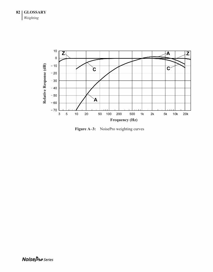
053-379, Rev E
GLOSSARYWeighting
82
Figure A–3: NoisePro weighting curves
Rel
ativ
e R
espo
nse
(dB
)
Frequency (Hz)
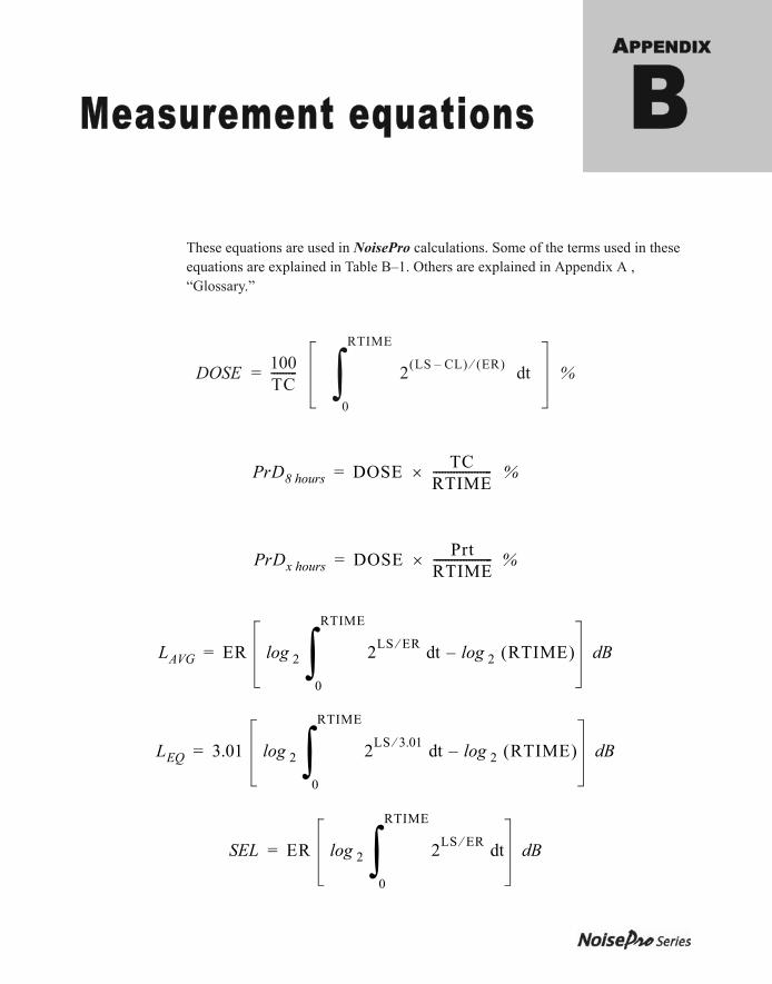
053-379, Rev E
APPENDIX
Measurement equations BThese equations are used in NoisePro calculations. Some of the terms used in these equations are explained in Table B–1. Others are explained in Appendix A , “Glossary.”
DOSE = 100TC--------- 2 LS CL– ER td
0
RTIME
%
PrD8 hours DOSE TCRTIME-------------------- %=
PrDx hours DOSE PrtRTIME-------------------- %=
LAVG ER log 2 2LS ER td log 2 RTIME–
0
RTIME
dB=
LEQ 3.01 log 2 2LS 3.01 td log 2 RTIME–
0
RTIME
dB=
SEL ER log 2 2LS ER td
0
RTIME
dB=
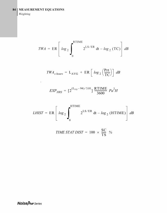
053-379, Rev E
84 MEASUREMENT EQUATIONSWeighting
.
TWA ER log 2 2LS ER td log 2 TC–
0
RTIME
dB=
TWAx hours LAVG ER log 2PrtTC--------- dB+=
EXPHRS 2LEQ 94– 3.01 RTIME
3600-------------------- Pa2H=
LHIST ER log 2 2LS ER td log 2 HTIME–
0
HTIME
dB=
TIME STAT DIST 100 SCTS------- %=
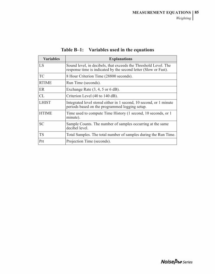
053-379, Rev E
MEASUREMENT EQUATIONSWeighting
85
Table B–1: Variables used in the equations
Variables ExplanationsLS Sound level, in decibels, that exceeds the Threshold Level. The
response time is indicated by the second letter (Slow or Fast).TC 8 Hour Criterion Time (28800 seconds).RTIME Run Time (seconds).ER Exchange Rate (3, 4, 5 or 6 dB).CL Criterion Level (40 to 140 dB).LHIST Integrated level stored either in 1 second, 10 second, or 1 minute
periods based on the programmed logging setup.HTIME Time used to compute Time History (1 second, 10 seconds, or 1
minute).SC Sample Counts. The number of samples occurring at the same
decibel level.TS Total Samples. The total number of samples during the Run Time.Prt Projection Time (seconds).

053-379, Rev E
MEASUREMENT EQUATIONS86
This page intentionally left blank
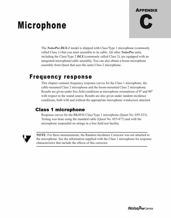
053-379, Rev E
APPENDIX
Microphone CThe NoisePro DLX-1 model is shipped with Class/Type 1 microphone (commonly called Class 1) that you must assemble to its cable. All other NoisePro units, including the Class/Type 2 DLX (commonly called Class 2), are equipped with an integrated microphone/cable assembly. You can also obtain a boom microphone assembly from Quest that uses the same Class 2 microphone.
Frequency responseThis chapter contains frequency response curves for the Class 1 microphone, the cable-mounted Class 2 microphone and the boom-mounted Class 2 microphone. Results are given under free field conditions at microphone orientations of 0o and 90o with respect to the sound source. Results are also given under random incidence conditions, both with and without the appropriate microphone windscreen attached.
Class 1 microphoneResponse curves for the BK4936 Class/Type 1 microphone (Quest No. 059-523). Testing was done using the standard cable (Quest No. 053-877) and with the microphone suspended on strings in a free field test facility.
NOTE: For these measurements, the Random Incidence Corrector was not attached to the microphone. See the information supplied with the Class 1 microphone for response characteristics that include the effects of this corrector.
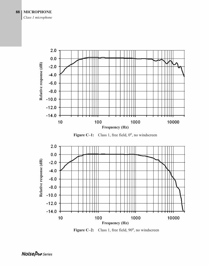
053-379, Rev E
88 MICROPHONEClass 1 microphone
Figure C–1: Class 1, free field, 0o, no windscreen
Figure C–2: Class 1, free field, 90o, no windscreen
Frequency (Hz)
Rel
ativ
e re
spon
se (d
B)
Frequency (Hz)
Rel
ativ
e re
spon
se (d
B)
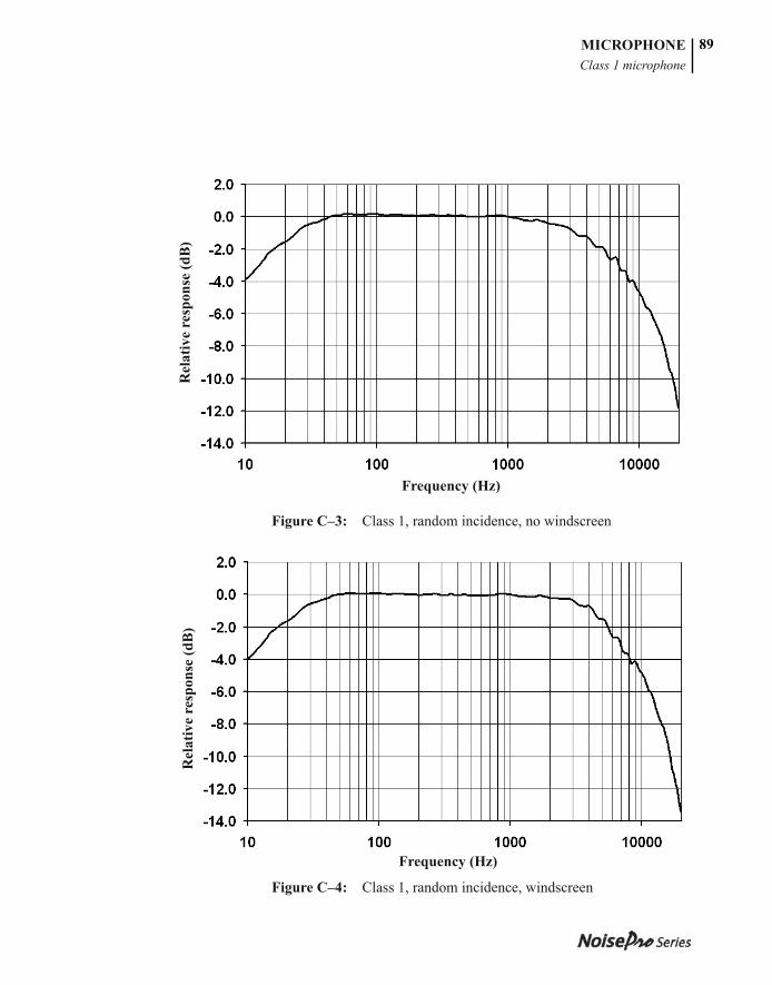
053-379, Rev E
MICROPHONEClass 1 microphone
89
Figure C–3: Class 1, random incidence, no windscreen
Figure C–4: Class 1, random incidence, windscreen
Frequency (Hz)
Rel
ativ
e re
spon
se (d
B)
Frequency (Hz)
Rel
ativ
e re
spon
se (d
B)
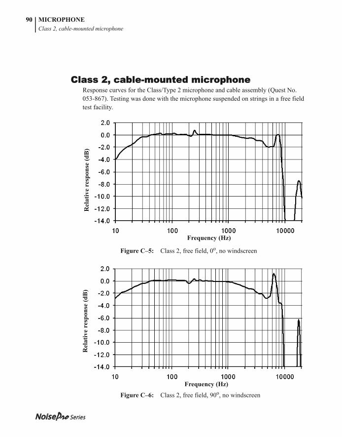
053-379, Rev E
MICROPHONEClass 2, cable-mounted microphone
90
Class 2, cable-mounted microphoneResponse curves for the Class/Type 2 microphone and cable assembly (Quest No. 053-867). Testing was done with the microphone suspended on strings in a free field test facility.
Figure C–5: Class 2, free field, 0o, no windscreen
Figure C–6: Class 2, free field, 90o, no windscreen
Frequency (Hz)
Rel
ativ
e re
spon
se (d
B)
Frequency (Hz)
Rel
ativ
e re
spon
se (d
B)
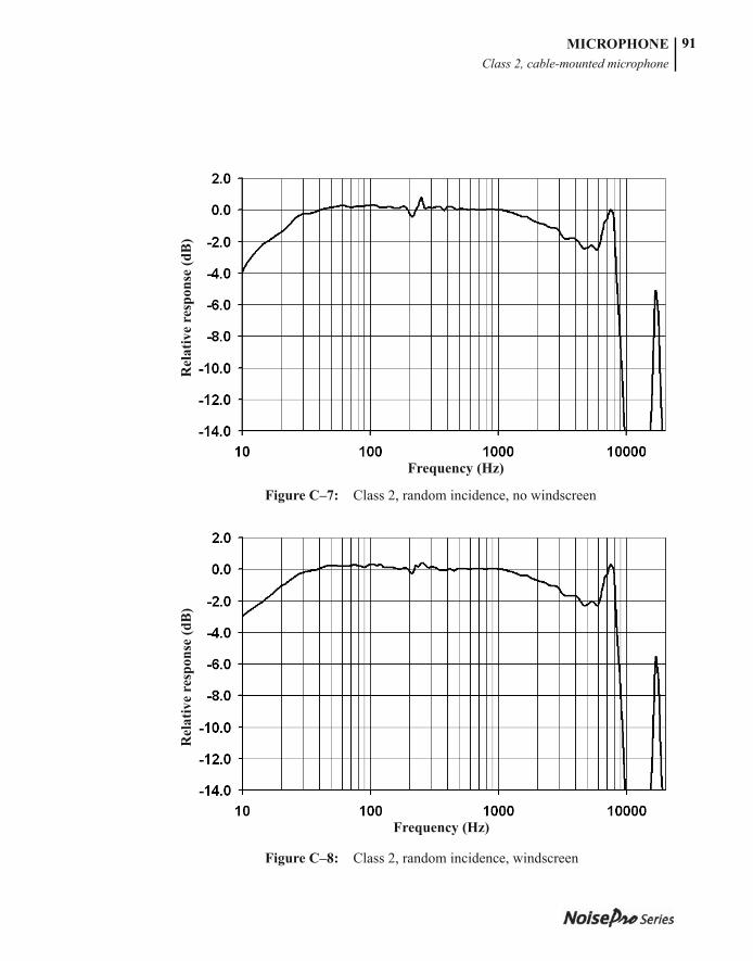
053-379, Rev E
MICROPHONEClass 2, cable-mounted microphone
91
Figure C–7: Class 2, random incidence, no windscreen
Figure C–8: Class 2, random incidence, windscreen
Frequency (Hz)
Rel
ativ
e re
spon
se (d
B)
Frequency (Hz)
Rel
ativ
e re
spon
se (d
B)
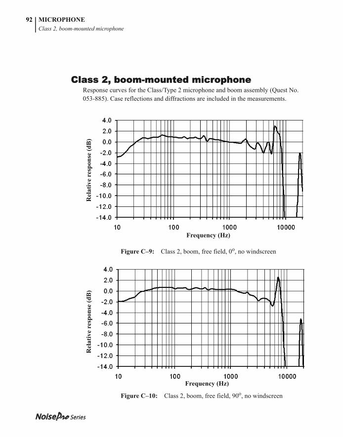
053-379, Rev E
MICROPHONEClass 2, boom-mounted microphone
92
Class 2, boom-mounted microphoneResponse curves for the Class/Type 2 microphone and boom assembly (Quest No. 053-885). Case reflections and diffractions are included in the measurements.
Figure C–9: Class 2, boom, free field, 0o, no windscreen
Figure C–10: Class 2, boom, free field, 90o, no windscreen
Frequency (Hz)
Rel
ativ
e re
spon
se (d
B)
Frequency (Hz)
Rel
ativ
e re
spon
se (d
B)
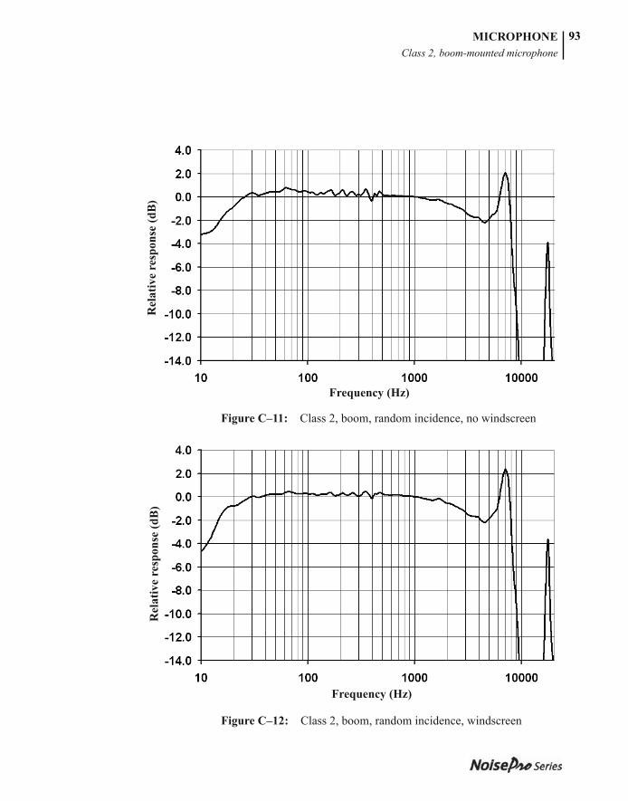
053-379, Rev E
MICROPHONEClass 2, boom-mounted microphone
93
Figure C–11: Class 2, boom, random incidence, no windscreen
Figure C–12: Class 2, boom, random incidence, windscreen
Frequency (Hz)
Rel
ativ
e re
spon
se (d
B)
Frequency (Hz)
Rel
ativ
e re
spon
se (d
B)

053-379, Rev E
MICROPHONE94
This page intentionally left blank
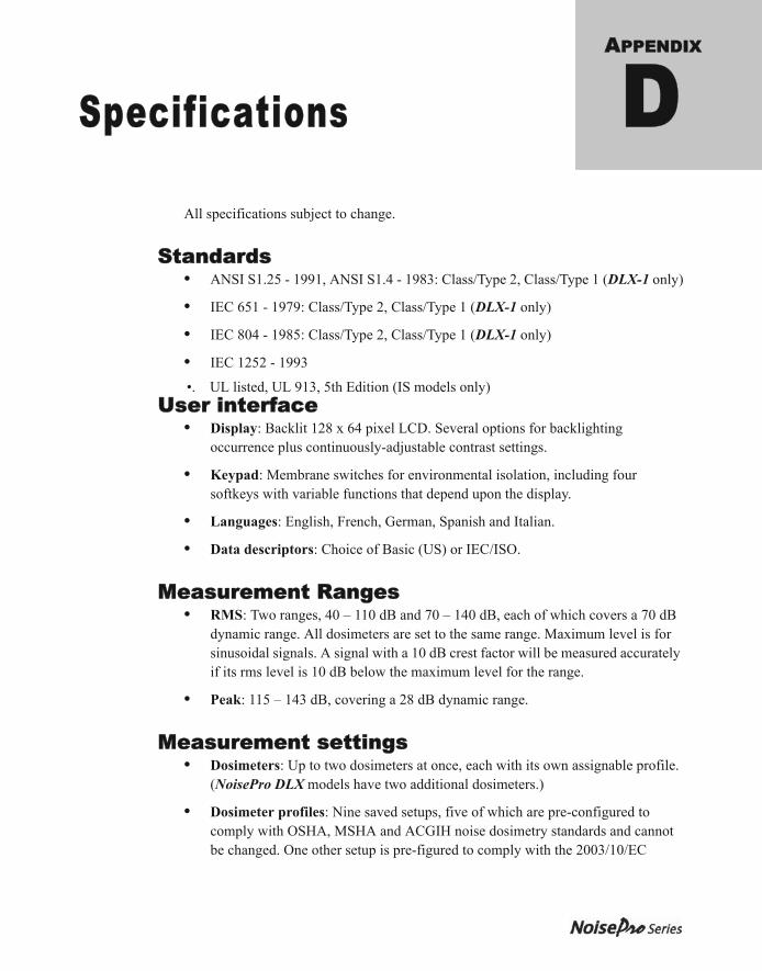
053-379, Rev E
APPENDIX
Specifications DAll specifications subject to change.
Standards• ANSI S1.25 - 1991, ANSI S1.4 - 1983: Class/Type 2, Class/Type 1 (DLX-1 only)
• IEC 651 - 1979: Class/Type 2, Class/Type 1 (DLX-1 only)
• IEC 804 - 1985: Class/Type 2, Class/Type 1 (DLX-1 only)
• IEC 1252 - 1993
•. UL listed, UL 913, 5th Edition (IS models only)
User interface• Display: Backlit 128 x 64 pixel LCD. Several options for backlighting
occurrence plus continuously-adjustable contrast settings.
• Keypad: Membrane switches for environmental isolation, including four softkeys with variable functions that depend upon the display.
• Languages: English, French, German, Spanish and Italian.
• Data descriptors: Choice of Basic (US) or IEC/ISO.
Measurement Ranges• RMS: Two ranges, 40 – 110 dB and 70 – 140 dB, each of which covers a 70 dB
dynamic range. All dosimeters are set to the same range. Maximum level is for sinusoidal signals. A signal with a 10 dB crest factor will be measured accurately if its rms level is 10 dB below the maximum level for the range.
• Peak: 115 – 143 dB, covering a 28 dB dynamic range.
Measurement settings• Dosimeters: Up to two dosimeters at once, each with its own assignable profile.
(NoisePro DLX models have two additional dosimeters.)
• Dosimeter profiles: Nine saved setups, five of which are pre-configured to comply with OSHA, MSHA and ACGIH noise dosimetry standards and cannot be changed. One other setup is pre-figured to comply with the 2003/10/EC
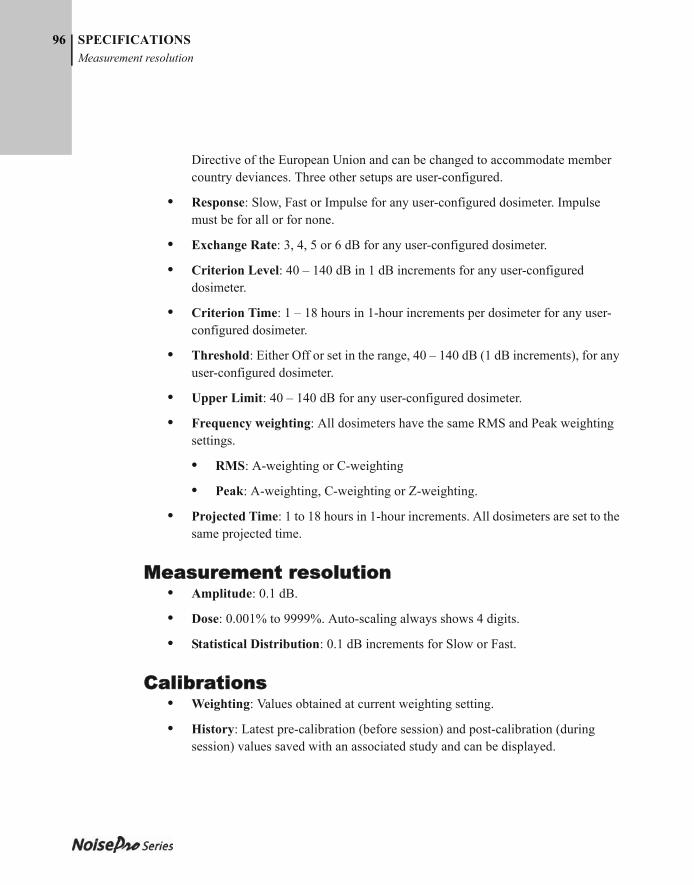
053-379, Rev E
96 SPECIFICATIONSMeasurement resolution
Directive of the European Union and can be changed to accommodate member country deviances. Three other setups are user-configured.
• Response: Slow, Fast or Impulse for any user-configured dosimeter. Impulse must be for all or for none.
• Exchange Rate: 3, 4, 5 or 6 dB for any user-configured dosimeter.
• Criterion Level: 40 – 140 dB in 1 dB increments for any user-configured dosimeter.
• Criterion Time: 1 – 18 hours in 1-hour increments per dosimeter for any user-configured dosimeter.
• Threshold: Either Off or set in the range, 40 – 140 dB (1 dB increments), for any user-configured dosimeter.
• Upper Limit: 40 – 140 dB for any user-configured dosimeter.
• Frequency weighting: All dosimeters have the same RMS and Peak weighting settings.
• RMS: A-weighting or C-weighting
• Peak: A-weighting, C-weighting or Z-weighting.
• Projected Time: 1 to 18 hours in 1-hour increments. All dosimeters are set to the same projected time.
Measurement resolution• Amplitude: 0.1 dB.
• Dose: 0.001% to 9999%. Auto-scaling always shows 4 digits.
• Statistical Distribution: 0.1 dB increments for Slow or Fast.
Calibrations• Weighting: Values obtained at current weighting setting.
• History: Latest pre-calibration (before session) and post-calibration (during session) values saved with an associated study and can be displayed.
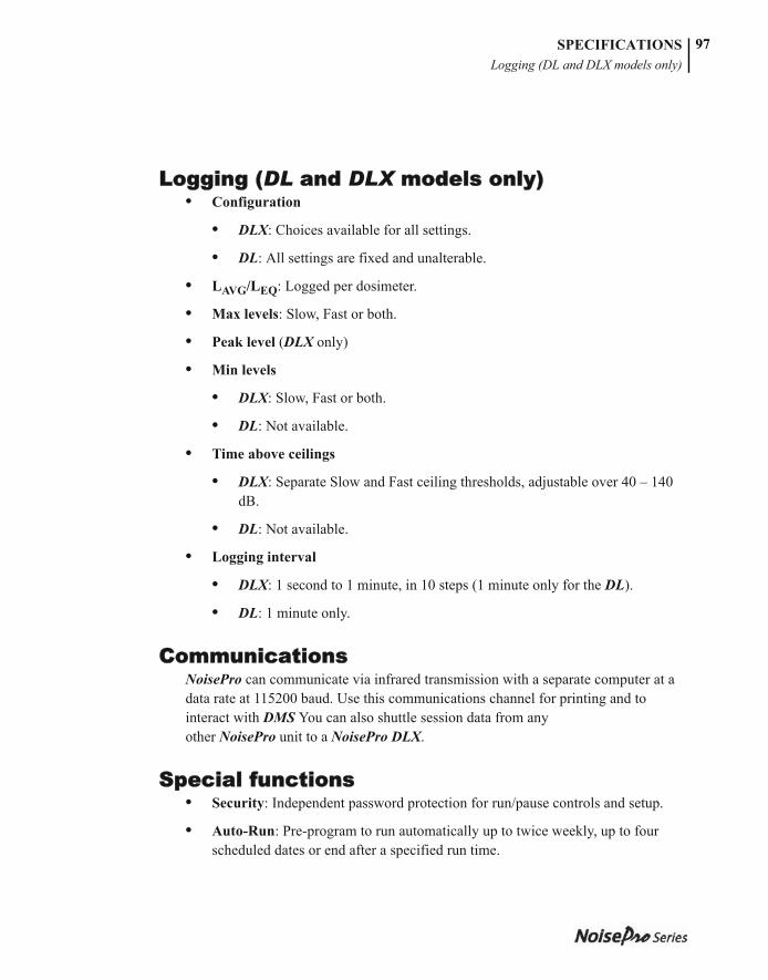
053-379, Rev E
SPECIFICATIONSLogging (DL and DLX models only)
97
Logging (DL and DLX models only)• Configuration
• DLX: Choices available for all settings.
• DL: All settings are fixed and unalterable.
• LAVG/LEQ: Logged per dosimeter.
• Max levels: Slow, Fast or both.
• Peak level (DLX only)
• Min levels
• DLX: Slow, Fast or both.
• DL: Not available.
• Time above ceilings
• DLX: Separate Slow and Fast ceiling thresholds, adjustable over 40 – 140 dB.
• DL: Not available.
• Logging interval
• DLX: 1 second to 1 minute, in 10 steps (1 minute only for the DL).
• DL: 1 minute only.
CommunicationsNoisePro can communicate via infrared transmission with a separate computer at a data rate at 115200 baud. Use this communications channel for printing and to interact with DMS You can also shuttle session data from any other NoisePro unit to a NoisePro DLX.
Special functions• Security: Independent password protection for run/pause controls and setup.
• Auto-Run: Pre-program to run automatically up to twice weekly, up to four scheduled dates or end after a specified run time.

053-379, Rev E
SPECIFICATIONSEnvironmental factors
98
Environmental factors• Operating temperature: +14 oF to +122 oF (–10 oC to +50 oC).
• Storage temperature: –13oF to +140 oF (–25 oC to +60 oC).
• Humidity: 0 to 95% non-condensing.
• Electromagnetic field effects: Negligible below 50 Oersteds at 50 to 60 Hz. Tested for RF succeptibility with <1dB error at field strengths to 10 V/m over the frequency range of 10 MHz to 500 MHz.
Electrical characteristics• Microphones:
• Class/Type 1 (DLX-1 only): 0.52 in. (12.2 mm), free field.
• Class/Type 2 (all other models): 0.335 in. (8.5 mm), random incidence.
• Memory: Data and settings stored in nonvolatile memory.
• Detector: True rms, 63 dB pulse range.
• Channels: One rms channel and one peak channel.
• Integration time: With a 3 dB Exchange Rate and a signal level of 140 dB the integration time would be one year or longer. Integration time is longer as the signal level decreases and the Exchange Rate increases.
• Date and time: Time resolved by seconds; 12-hour or 24-hour clock.
• Power needs:
• Two 1.5-volt, AA, replaceable alkaline cells. Select as specified under “Approved batteries” on page 65.
• Long-life Lithium battery to maintain time and date settings during battery replacement.
• Battery lifetime: The replaceable alkaline batteries have a lifetime of approximately 60 hours when neither the display backlighting nor the optional vibrating belt clip is used. If you select one of the backlighting options or are triggering vibrator alerts, battery lifetime can be substantially decreased.
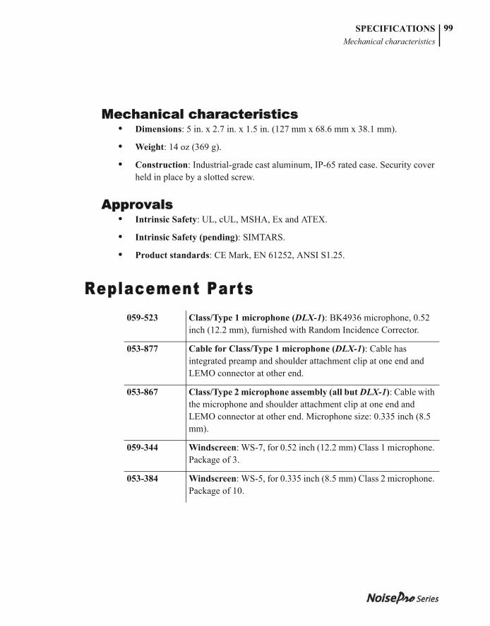
053-379, Rev E
SPECIFICATIONSMechanical characteristics
99
Mechanical characteristics• Dimensions: 5 in. x 2.7 in. x 1.5 in. (127 mm x 68.6 mm x 38.1 mm).
• Weight: 14 oz (369 g).
• Construction: Industrial-grade cast aluminum, IP-65 rated case. Security cover held in place by a slotted screw.
Approvals• Intrinsic Safety: UL, cUL, MSHA, Ex and ATEX.
• Intrinsic Safety (pending): SIMTARS.
• Product standards: CE Mark, EN 61252, ANSI S1.25.
Replacement Parts059-523 Class/Type 1 microphone (DLX-1): BK4936 microphone, 0.52
inch (12.2 mm), furnished with Random Incidence Corrector.
053-877 Cable for Class/Type 1 microphone (DLX-1): Cable has integrated preamp and shoulder attachment clip at one end and LEMO connector at other end.
053-867 Class/Type 2 microphone assembly (all but DLX-1): Cable with the microphone and shoulder attachment clip at one end and LEMO connector at other end. Microphone size: 0.335 inch (8.5 mm).
059-344 Windscreen: WS-7, for 0.52 inch (12.2 mm) Class 1 microphone. Package of 3.
053-384 Windscreen: WS-5, for 0.335 inch (8.5 mm) Class 2 microphone. Package of 10.
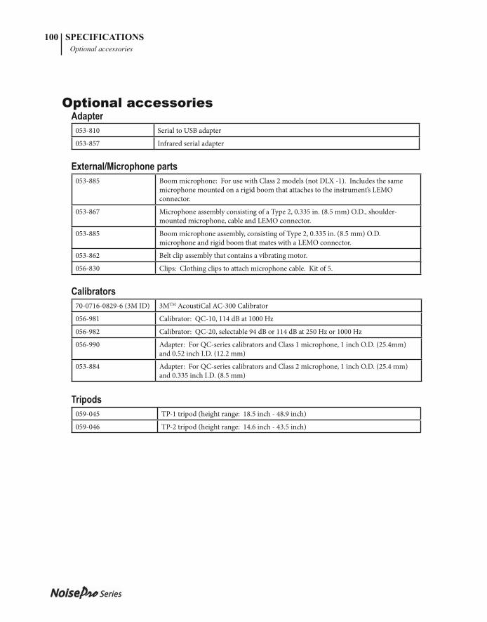
053-379, Rev E
100 SPECIFICATIONS Optional accessories
Optional accessoriesAdapter
053-810 Serial to USB adapter
053-857 Infrared serial adapter
External/Microphone parts053-885 Boom microphone: For use with Class 2 models (not DLX -1). Includes the same
microphone mounted on a rigid boom that attaches to the instrument’s LEMO connector.
053-867 Microphone assembly consisting of a Type 2, 0.335 in. (8.5 mm) O.D., shoulder-mounted microphone, cable and LEMO connector.
053-885 Boom microphone assembly, consisting of Type 2, 0.335 in. (8.5 mm) O.D. microphone and rigid boom that mates with a LEMO connector.
053-862 Belt clip assembly that contains a vibrating motor.
056-830 Clips: Clothing clips to attach microphone cable. Kit of 5.
Calibrators 70-0716-0829-6 (3M ID) 3MTM AcoustiCal AC-300 Calibrator
056-981 Calibrator: QC-10, 114 dB at 1000 Hz
056-982 Calibrator: QC-20, selectable 94 dB or 114 dB at 250 Hz or 1000 Hz
056-990 Adapter: For QC-series calibrators and Class 1 microphone, 1 inch O.D. (25.4mm) and 0.52 inch I.D. (12.2 mm)
053-884 Adapter: For QC-series calibrators and Class 2 microphone, 1 inch O.D. (25.4 mm) and 0.335 inch I.D. (8.5 mm)
Tripods059-045 TP-1 tripod (height range: 18.5 inch - 48.9 inch)
059-046 TP-2 tripod (height range: 14.6 inch - 43.5 inch)
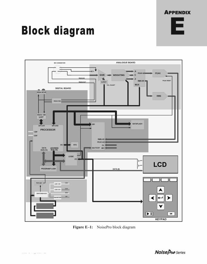
053-379, Rev E
APPENDIX
Block diagram E
Figure E–1: NoisePro block diagram

053-379, Rev E
BLOCK DIAGRAM102
This page intentionally left blank
053-379, Rev E
APPENDIX
Quest policies FService
International customers
United States customers only
Customer service
Contacting 3M Quest TechnologiesShould your 3M Quest Technologies equipment need to be returned for repair or for recalibration, please contact the service department at the following number or access the online form via the website. For technical issues, please contact Technical Support.
Service Department and Technical Support: 1 (800) 245-0779.
Fax: 1 (262) 567-4047. Offi ce hours are 8:00 a.m. to 5:00 p.m. United States Central. • E-mail: [email protected] • Internet: www.3M.com/detection
International customersContact your local, factory-authorized distributor from whom the product was purchased. You can obtain the name and contact information of your local factory-authorized distributor from Quest by using the e-mail, telephone, or fax information given under “Contacting 3M Quest Technologies” above.
Calibration Th e Sound Examiner and 3M Quest fi eld calibrator devices should be examined regularly by the factory. An annual calibration is recommended. (Please see Service Department above.)
053-379, Rev E
104 Customer Service Warranty
Warranty3M Quest Technologies warrants our instruments to be free from defects in materials and workmanship for one year under normal conditions of use and service. For United States customers, we will replace or repair (our option) defective instruments at no charge, excluding batteries, abuse, misuse, alterations, physical damage, or instruments previously repaired by other than 3M Quest Technologies. Microphones, sensors, printers, and chart recorders may have shorter or longer warranty periods. Th is warranty states our total obligation in place of any other warranties expressed or implied. Our warranty does not include any liability or obligation directly resulting from any defective instrument or product or any associated damages, injuries, or property loss, including loss of use or measurement data.For warranty outside the United States, a minimum of one year warranty applies subject to the same limitation and exceptions as above with service provided or arranged through the authorized Quest distributor or our 3M Quest European Service Laboratory. Foreign purchasers should contact the local 3M Quest authorized sales agent for detail.
053-379, Rev E
INDEX
AAccuracy . . . . . . . . . . . . . . . . . . . . . . . . . . . . .63ACGIH
Alert Level . . . . . . . . . . . . . . . . . . . . . . . .45Dosimeter setups . . . . . . . . . . . . . . . . . . .33Profile settings . . . . . . . . . . . . . . . . . . . . .34Standards organization . . . . . . . . . . . . . . . .1
Alert Levels, explained . . . . . . . . . . . . . . . . . .45Auto-Run . . . . . . . . . . . . . . . . . . . . . . . . . 20–24
Date mode . . . . . . . . . . . . . . . . . . . . . . . . .21Days of Week mode . . . . . . . . . . . . . . . . .23Enable/disable . . . . . . . . . . . . . . . . . . . . . .24Timed Run mode . . . . . . . . . . . . . . . . . . .22
Average sound level (LAVG) . . . . . . . . . . . . .76A-weighting, defined . . . . . . . . . . . . . . . . . . . .81
BBackground noise, removal . . . . . . . . . . . . . . .61Backlighting setup . . . . . . . . . . . . . . . . . . . . . .29Basic Descriptors . . . . . . . . . . . . . . . . . . . . . . .30Batteries
Lifetime . . . . . . . . . . . . . . . . . . . . . . . . . .98Lobat indicator . . . . . . . . . . . . . . . . . . . . . .9Replacement . . . . . . . . . . . . . . . . . . . . . . .65
Battery icon . . . . . . . . . . . . . . . . . . . . . . . . . . . .9Belt clip, install . . . . . . . . . . . . . . . . . . . . . . . .67Boom microphone
Connecting . . . . . . . . . . . . . . . . . . . . . . . . .8CCalendar . . . . . . . . . . . . . . . . . . . . . . . . . 20 NoteCalibration
Procedures . . . . . . . . . . . . . . . . . . . . 15–18Troubleshooting . . . . . . . . . . . . . . . . . . . .69
Calibrator . . . . . . . . . . . . . . . . . . . . . . . . . . . . .15Clock, setup . . . . . . . . . . . . . . . . . . . . . . . . . . .25Close Session . . . . . . . . . . . . . . . . . . . . . . . . . .14Closed Session icon . . . . . . . . . . . . . . . . . . . . .13
Code, recovery . . . . . . . . . . . . 49 Note, 49 NoteCombining levels, adding . . . . . . . . . . . . . . . . 62Comm display . . . . . . . . . . . . . . . . . . . . . . . . . 53Communication, troubleshooting . . . . . . . . . . 70Compliance indicators . . . . . . . . . . . . . . . . . . . 45Conflicts, resolution . . . . . . . . . . . . . . . . . . . . 38Cover, case . . . . . . . . . . . . . . . . . . . . . . . . . . . . 4Criterion Level, defined . . . . . . . . . . . . . . . . . 73Criterion Time, defined . . . . . . . . . . . . . . . . . . 73Cut Off
See “Threshold”C-weighting, defined . . . . . . . . . . . . . . . . . . . . 81
DData Results display . . . . . . . . . . . . . . . . . . . . 41Date
365-day limit . . . . . . . . . . . . . . . . . .20 NoteAutoRun Mode . . . . . . . . . . . . . . . . . . . . . 22Setup display . . . . . . . . . . . . . . . . . . . . . . 25
Date mode, Auto-Run . . . . . . . . . . . . . . . . . . . 21Day/Night sound level (LDN) . . . . . . . . . . . . . 77Days of Week, Auto-Run . . . . . . . . . . . . . . . . 23Decibel, defined . . . . . . . . . . . . . . . . . . . . . . . 73Descriptors
Basic defined . . . . . . . . . . . . . . . . . . . . . . 73Data Results display . . . . . . . . . . . . . . . . . 42Defined . . . . . . . . . . . . . . . . . . . . . . . . . . . 73Display Menu . . . . . . . . . . . . . . . . . . . . . . 30IEC/ISO explained . . . . . . . . . . . . . . . . . . 75
Display, backlighting . . . . . . . . . . . . . . . . . . . 29DL, logging report . . . . . . . . . . . . . . . . . . . . . . 60DLX models
Closing a session . . . . . . . . . . . . . . . . . . . 14Logging report . . . . . . . . . . . . . . . . . . . . . 60
DLX-1Microphone assembly . . . . . . . . . . . . . . . . 7Microphone response . . . . . . . . . . . . .87, 88
Dose
Index®
053-379, Rev E
INDEX106
Defined . . . . . . . . . . . . . . . . . . . . . . . . . . .74Equations . . . . . . . . . . . . . . . . . . . . . . . . .83
DosimeterData Results display . . . . . . . . . . . . . . . . .42Disable vibration . . . . . . . . . . . . . . 30 Note
Dosimeter setupsConflict resolution . . . . . . . . . . . . . . . . . .38Definition . . . . . . . . . . . . . . . . . . . . . . . . .33User setups . . . . . . . . . . . . . . . . . . . . . . . .34
Dynamic range, defined . . . . . . . . . . . . . . . . . . .1EE-mail Quest . . . . . . . . . . . . . . . . . . . . . . . . . .30Equations . . . . . . . . . . . . . . . . . . . . . . . . . . . . .83Equivalent sound level (LEQ) . . . . . . . . . . . . .77Escape key . . . . . . . . . . . . . . . . . . . . . . . . . . . . .9EU
Change setup . . . . . . . . . . . . . . . . . . 36, 37Directive . . . . . . . . . . . . . . . . . . . . . . . . . .33
ExceedanceDefined . . . . . . . . . . . . . . . . . . . . . . . . . . .74
Exchange Rate (ER)Defined . . . . . . . . . . . . . . . . . . . . . . . . . . .74
ExposureDaily personal (LEP,D) . . . . . . . . . . . . . .77Equation . . . . . . . . . . . . . . . . . . . . . . . . . .84Indicators . . . . . . . . . . . . . . . . . . . . . . . . .76
FFast Ceiling (FCEIL) . . . . . . . . . . . . . . . . . . . .26Fast response, curve . . . . . . . . . . . . . . . . . . . . .79Formulas . . . . . . . . . . . . . . . . . . . . . . . . . . . . .83
HHeader, reports . . . . . . . . . . . . . . . . . . . . . . . . .57Hearing Conservation (HC)
1983 Amendment . . . . . . . . . . . . . . . . . . .80Dosimeter setups values . . . . . . . . . . . . . .33Program definition . . . . . . . . . . . . . . . . . .75
Hertz (Hz), defined . . . . . . . . . . . . . . . . . . . . .75
IIEC/ISO descriptors . . . . . . . . . . . . . . . . . . . . 30Infrared
Comm Set display . . . . . . . . . . . . . . . . . . 28Hardware setup . . . . . . . . . . . . . . . . . . . . 51Troubleshooting . . . . . . . . . . . . . . . . . . . . 70
Interval, logging . . . . . . . . . . . . . . . . . . . . . . . 26
LLAVG
Defined . . . . . . . . . . . . . . . . . . . . . . . . . . . 76Equation . . . . . . . . . . . . . . . . . . . . . . . . . . 83
LDN, defined . . . . . . . . . . . . . . . . . . . . . . . . . . 77LEQ
Defined . . . . . . . . . . . . . . . . . . . . . . . . . . . 77Equation . . . . . . . . . . . . . . . . . . . . . . . . . . 83
LobatBattery replacement . . . . . . . . . . . . . . . . . 65Indicator . . . . . . . . . . . . . . . . . . . . . . . . . . . 9
LockLocked Run display . . . . . . . . . . . . . . . . . 48Softkey . . . . . . . . . . . . . . . . . . . . . . . . . . . 47
LoggingCeiling settings . . . . . . . . . . . . . . . . . . . . . 26Interval . . . . . . . . . . . . . . . . . . . . . . . . . . . 26Introduction . . . . . . . . . . . . . . . . . . . . . . . . 2Report . . . . . . . . . . . . . . . . . . . . . . . . . . . . 60Setup menu . . . . . . . . . . . . . . . . . . . . . . . . 26
MMax Level, defined . . . . . . . . . . . . . . . . . . . . . 77Microphone
Class 1, response . . . . . . . . . . . . . . . . . . . 87Class 2 boom, response . . . . . . . . . . . . . . 92Class 2 cable, response . . . . . . . . . . . . . . . 90Class 2 connection . . . . . . . . . . . . . . . . . . . 8Frequency response . . . . . . . . . . . . . . . . . 87Mounting . . . . . . . . . . . . . . . . . . . . . . . . . 12Position, dosimetry . . . . . . . . . . . . . . . . . . 11Position, SLM measurements . . . . . . . . . 12Response, Class 1 . . . . . . . . . . . . . . . .88–89
053-379, Rev E
INDEX 107
Response, Class 2 . . . . . . . . . . . . . . . 90–93Min Level, Defined . . . . . . . . . . . . . . . . . . . . .77MSHA
Alert Level . . . . . . . . . . . . . . . . . . . . . . . .45Dosimeter setups . . . . . . . . . . . . . . . . . . .33Profile settings . . . . . . . . . . . . . . . . . . . . .34Standards organization . . . . . . . . . . . . . . . .1
NNoise floor . . . . . . . . . . . . . . . . . . . . . . . . . . . .63
OOSHA
Alert Level . . . . . . . . . . . . . . . . . . . . . . . .45Dosimeter setups . . . . . . . . . . . . . . . . . . .33Profile settings . . . . . . . . . . . . . . . . . . . . .34Standards organization . . . . . . . . . . . . . . . .1Threshold standards . . . . . . . . . . . . . . . . .80TWA . . . . . . . . . . . . . . . . . . . . . . . . . . . . .80
OverloadIndicator . . . . . . . . . . . . . . . . . . . . . . . . . .43Session Report . . . . . . . . . . . . . . . . . . . . .58Study Report . . . . . . . . . . . . . . . . . . . . . . .59
PPause icon . . . . . . . . . . . . . . . . . . . . . . . . . . . .13Peak level, defined . . . . . . . . . . . . . . . . . . . . . .77Permissible Exposure Limit (PEL)
Defined . . . . . . . . . . . . . . . . . . . . . . . . . . .78Dosimeter setups . . . . . . . . . . . . . . . . . . .33
Personal monitoring, mounting . . . . . . . . . . . .12Power
On/Off . . . . . . . . . . . . . . . . . . . . . . . . . . . . .9Troubleshooting . . . . . . . . . . . . . . . . . . . .69
PrintingHardware setup . . . . . . . . . . . . . . . . . . . . .51Print display . . . . . . . . . . . . . . . . . . . . . . .54
Projected Time (PRJ), setup . . . . . . . . . . . . . .25
QQuest website . . . . . . . . . . . . . . . . . . . . . . . . . .30
RRandom Incidence Corrector
Applying it . . . . . . . . . . . . . . . . . . . . . . . . . 7Using it . . . . . . . . . . . . . . . . . . . . . . . . . . . 12
RangeChanging . . . . . . . . . . . . . . . . . . . . . . . . . 37Conflict resolution . . . . . . . . . . . . . . . . . . 38
Recovery CodeSecure Run Mode . . . . . . . . . . . . . . .49 NoteSecure Setup Mode . . . . . . . . . . . . .49 Note
ReportsControlling contents . . . . . . . . . . . . . . . . . 54Header section . . . . . . . . . . . . . . . . . . . . . 57Session section . . . . . . . . . . . . . . . . . . . . . 58Study section . . . . . . . . . . . . . . . . . . . . . . 59
ResetClears results . . . . . . . . . . . . . . . . . .39 NoteHow to . . . . . . . . . . . . . . . . . . . . . . . . . . . 11
ResponseConflict resolution . . . . . . . . . . . . . . . . . . 38Data Results display . . . . . . . . . . . . . . . . . 42Definitions . . . . . . . . . . . . . . . . . . . . . . . . 78
ResultsReview previous . . . . . . . . . . . . . . . . . . . . 40Summary display . . . . . . . . . . . . . . . . . . . 44View current . . . . . . . . . . . . . . . . . . . . . . . 39
RTIMESee “Run Time”
Run icon . . . . . . . . . . . . . . . . . . . . . . . . . . . . . 13Run Time
Data Results display . . . . . . . . . . . . . . . . . 42Defined . . . . . . . . . . . . . . . . . . . . . . . . . . . . 4
SSecure Run Mode . . . . . . . . . . . . . . . . . . .47–48
After shut down . . . . . . . . . . . . . . . .47 NoteDisable . . . . . . . . . . . . . . . . . . . . . . . . . . . 48Enable . . . . . . . . . . . . . . . . . . . . . . . . . . . . 47Locked Run display . . . . . . . . . . . . . . . . . 48Recovery Code . . . . . . . . . . . . . . . . .49 NoteStart study in . . . . . . . . . . . . . . . . . . . . . . 48
053-379, Rev E
INDEX108
Secure Setup ModeDisable . . . . . . . . . . . . . . . . . . . . . . . . . . .49Recovery Code . . . . . . . . . . . . . . . . 49 Note
Secure Setup Mode, Shutdown . . . . . . . 49 NoteSerial number . . . . . . . . . . . . . . . . . . . . . . . . . .30Session
Closing DLX session . . . . . . . . . . . . . . . .14Introduced . . . . . . . . . . . . . . . . . . . . . . . . . .2Report . . . . . . . . . . . . . . . . . . . . . . . . . . . .58Run Time . . . . . . . . . . . . . . . . . . . . . . . . . .4
Session counter, increment . . . . . . . . . . . . . . .14Setup, dosimeter
See "Dosimeter setups"Shuttle
Introduction . . . . . . . . . . . . . . . . . . . . . . .51Procedure . . . . . . . . . . . . . . . . . . . . . . . . .54
Slow Ceiling (SCEIL) . . . . . . . . . . . . . . . . . . .26Slow response, curve . . . . . . . . . . . . . . . . . . . .78Sound Exposure Level (SEL)
Defined . . . . . . . . . . . . . . . . . . . . . . . . . . .79Equation . . . . . . . . . . . . . . . . . . . . . . . . . .84
Sound Level MeterMicrophone position . . . . . . . . . . . . . . . . .12SPL measurement . . . . . . . . . . . . . . . . . . .44
StudyReport . . . . . . . . . . . . . . . . . . . . . . . . . . . .59Secure Run Mode . . . . . . . . . . . . . . . . . . .48
Summary results . . . . . . . . . . . . . . . . . . . . . . .44
TThreshold, defined . . . . . . . . . . . . . . . . . . . . . .80Time Weighted Average (TWA)
Defined . . . . . . . . . . . . . . . . . . . . . . . . . . .80Equations . . . . . . . . . . . . . . . . . . . . . . . . .84
Time, setup . . . . . . . . . . . . . . . . . . . . . . . . . . .25Timed Run, Auto-Run . . . . . . . . . . . . . . . . . . .22Trigger
Enable, vibration . . . . . . . . . . . . . . . . . . . .31Vibration . . . . . . . . . . . . . . . . . . . . . . . . . .31
Tripod, using . . . . . . . . . . . . . . . . . . . . . . . . . .12
UUpper Limit, defined . . . . . . . . . . . . . . . . . . . . 81USB . . . . . . . . . . . . . . . . . . . . . . . . . . . . . . . . . 51User settings, lock . . . . . . . . . . . . . . . . . . . . . . 49User setups
Compliance indicators . . . . . . . . . . . . . . . 45Dosimeter setups . . . . . . . . . . . . . . . . . . . 34
VValidity . . . . . . . . . . . . . . . . . . . . . . . . . . . . . . 63Vibration
Belt clip installation . . . . . . . . . . . . . . . . . 67Enable trigger . . . . . . . . . . . . . . . . . . . . . . 31Rate . . . . . . . . . . . . . . . . . . . . . . . . . . . . . 30Trigger setup . . . . . . . . . . . . . . . . . . . . . . 31Troubleshooting . . . . . . . . . . . . . . . . . . . . 70
View current data . . . . . . . . . . . . . . . . . . . . . . 39
WWebsite, Quest . . . . . . . . . . . . . . . . . . . . . . . . 30Weighting
Changing . . . . . . . . . . . . . . . . . . . . . . . . . 37Conflict resolution . . . . . . . . . . . . . . . . . . 38Conflicts . . . . . . . . . . . . . . . . . . . . . . . . . . 38Defined . . . . . . . . . . . . . . . . . . . . . . . . . . . 81
WindscreenEffect on frequency response . . . . . . . . . . 87Using . . . . . . . . . . . . . . . . . . . . . . . . . . . . 11
ZZ-weighting, defined . . . . . . . . . . . . . . . . . . . . 81
www.3M.com/detection
3M is a trademark of 3M Company, used under license in Canada.
Please recycle. Printed in USA.© 2014 3M Company. All rights reserved.053-379, Rev.H 1/14
About Us3M Detection Solutions is a world class manufacturer of rugged, reliable instrumentation and software systems that help monitor and evaluate occupational and environmental health and safety hazards, including noise dosimetry, sound level monitoring, heat stress, indoor air quality and select toxic/combustible gases. The 3M Detection brand of instrumentation is used by safety and industrial hygiene professionals to help comply with applicable occupational standards and regulations.
About 3M Personal Safety3M offers a comprehensive, diverse portfolio of Personal Safety solutions providing respiratory protection, hearing protection, fall protection, reflective materials for high visibility, protective clothing, protective eyewear, head and face protection, welding helmets, and other adjacent products and solutions such as tactical safety equipment,detection, monitoring equipment, active communications equipment and compliance management. In 2012, 3M celebrated 40 years of safety leadership – recognizing the company’s respiratory and hearing protection solutions introduced in 1972. Visit www.3M.com/PPESafety or http://m.3m.com/PPESafety for details.
Personal Safety Division3M Detection SolutionsISO 9001 Registered CompanyISO 17025 Accredited Calibration Lab1060 Corporate Center DriveOconomowoc, WI 53066Customer Service: 262-567-9157Toll Free: 800-245-0779
3M™ NoisePro™ Personal Noise Dosimeters