3M Indoor Protected Building Entrance Terminal 4588V … 4588V-QCS Series ... 3.2 Run the feeder...
10
3M ™ Indoor Protected Building Entrance Terminal 4588V-QCS Series with 3M ™ Quick Connect System 2811 Dry Flame Retardant Block Instructions Underwriters Laboratories (UL 348X) Listed April 2010 78-0013-1813-4-A 3
Transcript of 3M Indoor Protected Building Entrance Terminal 4588V … 4588V-QCS Series ... 3.2 Run the feeder...
3M™IndoorProtectedBuildingEntranceTerminal4588V-QCSSerieswith3M™QuickConnectSystem2811DryFlameRetardantBlock
InstructionsUnderwriters Laboratories (UL 348X) Listed
April 201078-0013-1813-4-A 3
2 78-0013-1813-4-A
1.0 General
The3M™IndoorProtectedBuildingEntranceTerminal(IBET)4588V-QCSSeriesprovideselectricalprotectionandaterminationpointforoutsideplantcable(feeder)andindoorhousewiring(distribution).The4588V-QCSIBETisUnderwritersLaboratories(UL348X)Listed.
1.1 4588SeriesIBETNames,PairCapacityandModule
4588QCS-HCCA/25SD 25-pair HiCat Indoor Building Entrance Terminal with 710 SD
4588QCS-HCCA/50SD 50-pair HiCat Indoor Building Entrance Terminal with 710 SD
4588QCS-HCCA/100SD 100-pair HiCat Indoor Building Entrance Terminal with 710 SD
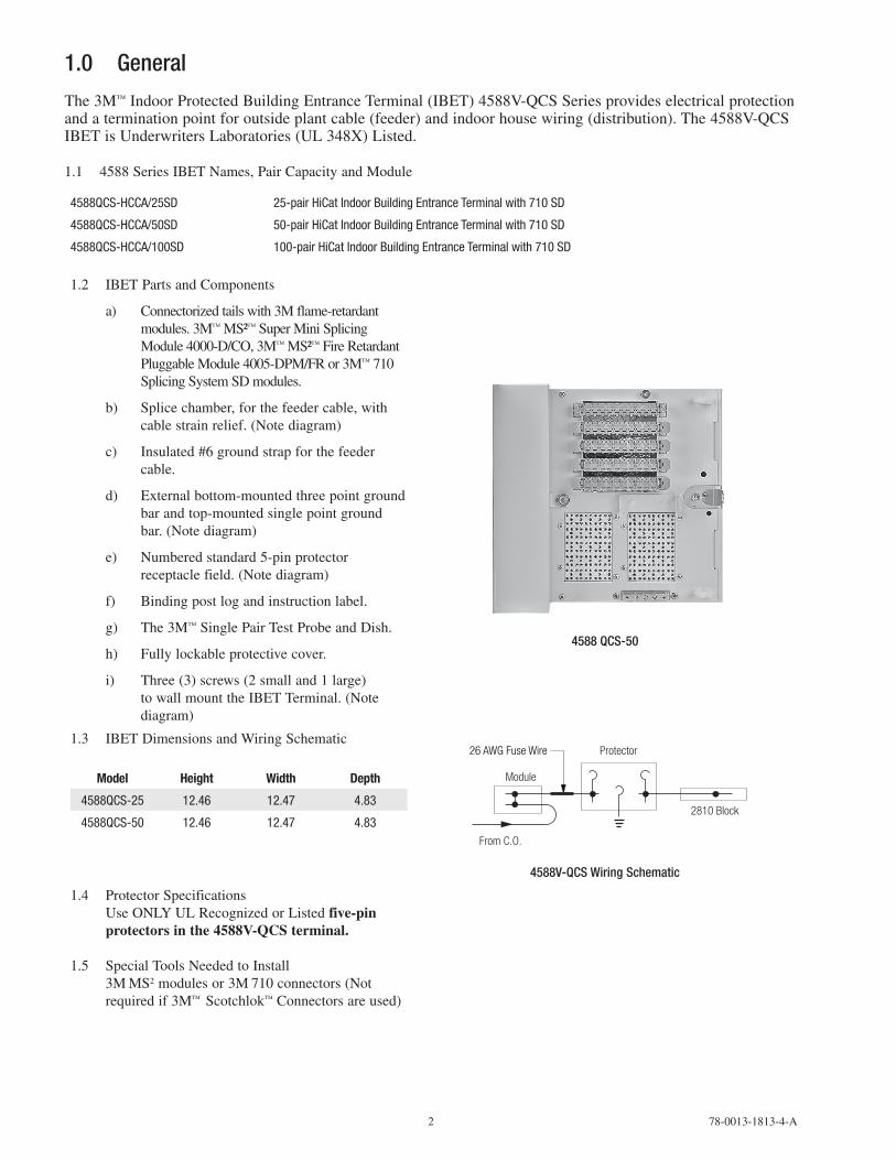
1.2 IBETPartsandComponents
a) Connectorizedtailswith3Mflame-retardantmodules.3M™MS²™SuperMiniSplicingModule4000-D/CO,3M™MS²™FireRetardantPluggableModule4005-DPM/FRor3M™710SplicingSystemSDmodules.
b) Splicechamber,forthefeedercable,withcablestrainrelief.(Notediagram)
c) Insulated#6groundstrapforthefeedercable.
d) Externalbottom-mountedthreepointgroundbarandtop-mountedsinglepointgroundbar.(Notediagram)
e) Numberedstandard5-pinprotectorreceptaclefield.(Notediagram)
f) Bindingpostlogandinstructionlabel.
g) The3M™SinglePairTestProbeandDish.
h) Fullylockableprotectivecover.
i) Three(3)screws(2smalland1large)towallmounttheIBETTerminal.(Notediagram)
4588QCS-50
1.3 IBETDimensionsandWiringSchematic
Model Height Width Depth
4588QCS-25 12.46 12.47 4.83
4588QCS-50 12.46 12.47 4.83
Module
From C.O.
Protector
2810 Block
26 AWG Fuse Wire
4588V-QCSWiringSchematic
1.4 ProtectorSpecificationsUseONLYULRecognizedorListedfive-pin protectors in the 4588V-QCS terminal.
1.5 SpecialToolsNeededtoInstall3MMS2modulesor3M710connectors(Notrequiredif3M™Scotchlok™Connectorsareused)
78-0013-1813-4-A 3
2.0 TerminalLocationandMounting2.1 Locatetheterminalaccordingtostandard
operatingprocedures.Considerthefollowingpoints:
a) Locatetheterminalinsidethebuildingascloseaspossibletocableentrance.
b) Locatetheterminalonafirmmountingsurfacewhereitwillbeaccessibletothetechniciansatalltimes;whereitcanbereachedwithoutaladder;andwhereitwillnotprojectinahazardousmanner.
c) Observecautionwhenexposingtheterminaltochemicalsinliquidorvaporformastheymaydamagetheplasticcomponents.
CAUTIONAvoid locations near flammable materials, ignitable gases, dust, moisture, temperature extremes, moving machinery, electric light and power circuits, and electrical equipment.
2.2 Openthesplicingchamberbylooseningtheboltsecuringthesplicingchamberdoor.Openthesplicingchamberdoor.(See-fig.7.02)
2.3 Pullthepreterminatedshortstub,insulatedgroundwire,andaccessoriesoutofthesplicingchamber.
2.4 Mounttheterminalindesignatedpositionwiththethreemountingscrewsprovided.
2.5 Removethejumperwireretainingringfrompolybagandinstallinfaceplate.
3.0 FeederCablePreparationandStrainRelief3.1 Feedercablediametersforthe3M™IndoorBuildingEntranceTerminal(IBET)4588V-QCSSeries
PET Pair CountFeeder Cable
Minimum Maximum Diameter Diameter
25 .42" 1.08"
50 .63" 1.45"
If the cable diameter is smaller than the minimum, use 3M™ 130C tape to build up to the minimum.
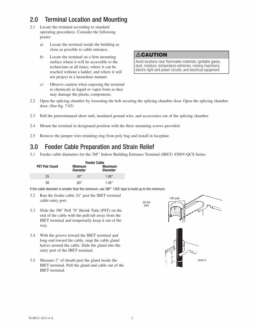
3.2 Runthefeedercable24"pasttheIBETterminalcableentryport.
3.3 Slidethe3M™Pull’N’ShrinkTube(PST)ontheendofthecablewiththepull-tabawayfromtheIBETterminalandtemporarilykeepitoutoftheway.
3.4 WiththegroovetowardtheIBETterminalandlongendtowardthecable,snapthecableglandhalvesaroundthecable.SlidetheglandintotheentryportoftheIBETterminal.
3.5 Measure2"ofsheathpasttheglandinsidetheIBETterminal.PulltheglandandcableoutoftheIBETterminal.
8430142"
25-50pair
100 pair
4 78-0013-1813-4-A
3.6 Removethesheath,leavingatleast21"offreeconductorlength.Identifyandsecurethecablegroupsends.Bondthecableshieldaccordingtoyourcompany’spractice.
3.7 Insertthegland’sgrooveintothecableport.Slidethe3M™Pull’N’ShrinkTube(PST)overtheglandandslowlyunwindthecore.ThePSTfitsovereitherthesmalldiameterofthe25-50pairglandorbuttsupagainstthe3M™IndoorBuildingEntranceTerminal(IBET)4588V-QCSforthe100pairgland.
822357
25-50pair
843016
3.8 CompletethePSTcoreremovaloverthegland.
3.9 TheblankplateMUSTbeusedintheemptycableportforULListing.
3.10 Attachthecabletothewallaccordingtoyourcompany’spractice.
4.0 TerminalGrounding4.1 Fastena#6AWGwiretothegroundbarwhichislocatedonthefrontoftheunit.Connectotherendofground
wiretolocalgroundpercompanystandards.
Note: FailuretoproperlybondandgroundtheterminalperN.E.C.orlocalequivalentcodesmayrenderprotectionarrestorsuseless.
4.2 Modulesplicing.Spliceperyourcompanypractice.
4.3 Splicethefeedercablegroupstothecorrespondingconnectorizedstubsaccordingtoyourcompany’spractice.
4.4 3M™Scotchlok™Connectororindividualconnectorsplicing
4.5 SplicethefeedercablegroupstothecorrespondingconnectorizedstubsintheIBETterminalaccordingtoyourcompany’spractice.
4.6 Whenallsplicingiscompleted,bundlethegroupsandsecurethemwithtiewrapsintothesplicechamberontheleftside.
4.7 ClosetheIBETterminalsplicechambercoverandsecurewiththelockplatebolt.(See7.02)
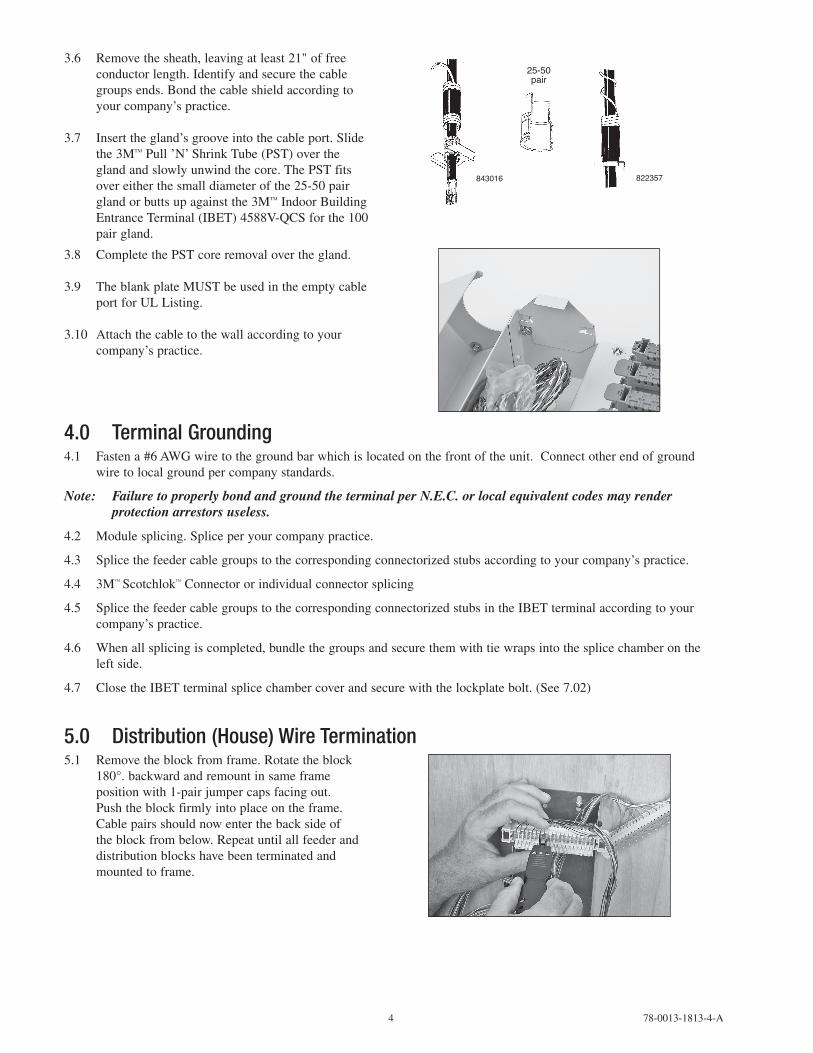
5.0 Distribution(House)WireTermination5.1 Removetheblockfromframe.Rotatetheblock
180°.backwardandremountinsameframepositionwith1-pairjumpercapsfacingout.Pushtheblockfirmlyintoplaceontheframe.Cablepairsshouldnowenterthebacksideoftheblockfrombelow.Repeatuntilallfeederanddistributionblockshavebeenterminatedandmountedtoframe.
78-0013-1813-4-A 5
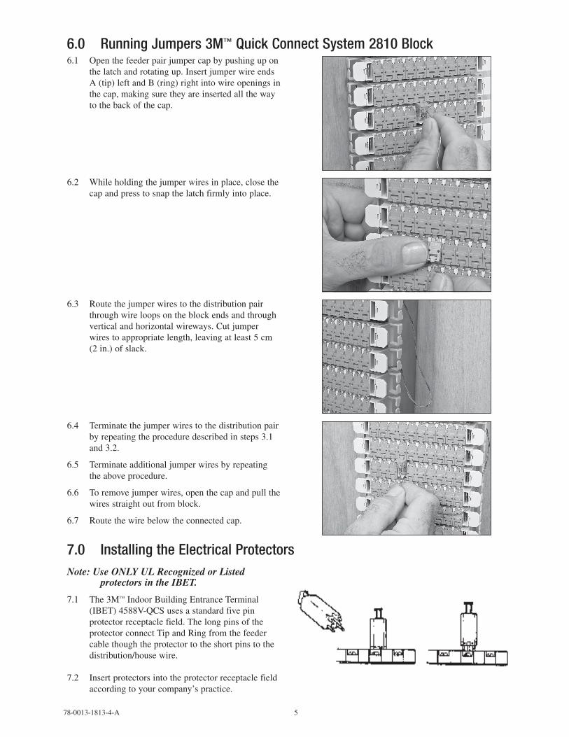
6.0 RunningJumpers3M™QuickConnectSystem2810Block6.1 Openthefeederpairjumpercapbypushingupon
thelatchandrotatingup.InsertjumperwireendsA(tip)leftandB(ring)rightintowireopeningsinthecap,makingsuretheyareinsertedallthewaytothebackofthecap.
6.2 Whileholdingthejumperwiresinplace,closethecapandpresstosnapthelatchfirmlyintoplace.
6.3 Routethejumperwirestothedistributionpairthroughwireloopsontheblockendsandthroughverticalandhorizontalwireways.Cutjumperwirestoappropriatelength,leavingatleast5cm(2in.)ofslack.
6.4 Terminatethejumperwirestothedistributionpairbyrepeatingtheproceduredescribedinsteps3.1and3.2.
6.5 Terminateadditionaljumperwiresbyrepeatingtheaboveprocedure.
6.6 Toremovejumperwires,openthecapandpullthewiresstraightoutfromblock.
6.7 Routethewirebelowtheconnectedcap.
7.0 InstallingtheElectricalProtectorsNote:UseONLYULRecognizedorListed
protectorsintheIBET.
7.1 The3M™IndoorBuildingEntranceTerminal(IBET)4588V-QCSusesastandardfivepinprotectorreceptaclefield.ThelongpinsoftheprotectorconnectTipandRingfromthefeedercablethoughtheprotectortotheshortpinstothedistribution/housewire.
7.2 Insertprotectorsintotheprotectorreceptaclefieldaccordingtoyourcompany’spractice.

6 78-0013-1813-4-A
7.3 Todisconnectthedistributionwire,pulltheprotectorouttothedetentsonthelongpinstoholditinplace.Thiscontinuestoprotectfromthefeedercableside.
8.0 ProtectiveCover8.1 Withthecoverclosed,theexposedhaspallowsfor
lockingwhensecurityisrequired.
9.0 3M™SinglePairTestProbe28279.1 Testingusing3M™SinglePairTestProbe2827
9.2 Plugthetestprobeintothecapofthepairbeingtested,withtheblackleadtotheleftandtheredleadtotheright.
10.0 3M™PriorityCaps10.1 PriorityCapsareusedtodesignatespecialpurpose
circuitsandprevententryofthe3MSinglePairTestProbe.
78-0013-1813-4-A 7
10.2 ToinstallPriorityCaps,placeoverthejumpercapofthepairtobemarkedandpushitintoplace.Latchingisindicatedbyanaudiblesnap.
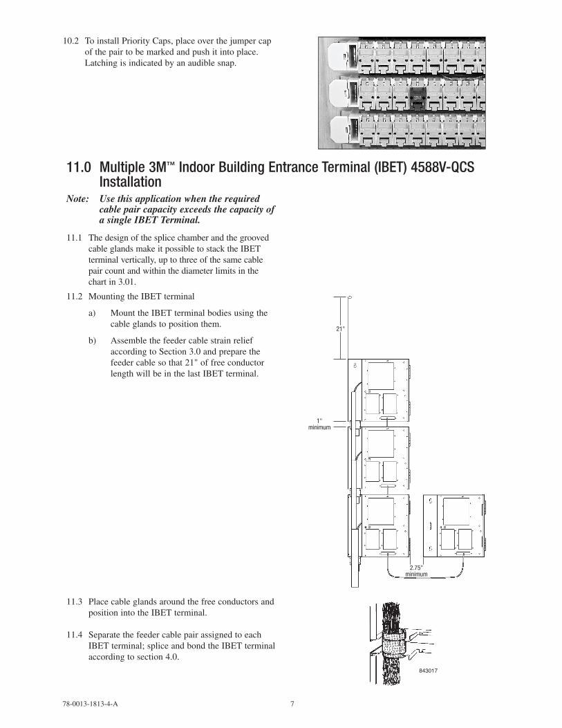
11.0 Multiple3M™IndoorBuildingEntranceTerminal(IBET)4588V-QCSInstallation
Note: UsethisapplicationwhentherequiredcablepaircapacityexceedsthecapacityofasingleIBETTerminal.
11.1 ThedesignofthesplicechamberandthegroovedcableglandsmakeitpossibletostacktheIBETterminalvertically,uptothreeofthesamecablepaircountandwithinthediameterlimitsinthechartin3.01.
11.2 MountingtheIBETterminal
a) MounttheIBETterminalbodiesusingthecableglandstopositionthem.
b) AssemblethefeedercablestrainreliefaccordingtoSection3.0andpreparethefeedercablesothat21"offreeconductorlengthwillbeinthelastIBETterminal.
1" minimum
21"
2.75" minimum
11.3 PlacecableglandsaroundthefreeconductorsandpositionintotheIBETterminal.
11.4 SeparatethefeedercablepairassignedtoeachIBETterminal;spliceandbondtheIBETterminalaccordingtosection4.0.
843017

8 78-0013-1813-4-A

78-0013-1813-4-A 9

3M, MS2 and Scotchlok are trademarks of 3M Company.
Important NoticeAll statements, technical information, and recommendations related to 3M’s products are based on information believed to be reliable, but the accuracy or completeness is not guaranteed. Before using this product, you must evaluate it and determine if it is suitable for your intended application. You assume all risks and liability associated with such use. Any statements related to the product which are not contained in 3M’s current publications, or any contrary statements contained on your purchase order shall have no force or effect unless expressly agreed upon, in writing, by an authorized officer of 3M.
Warranty; Limited Remedy; Limited Liability. This product will be free from defects in material and manufacture for a period of one (1) year from the time of purchase. 3M MAKES NO OTHER WARRANTIES INCLUDING, BUT NOT LIMITED TO, ANY IMPLIED WARRANTY OF MERCHANTABILITY OR FITNESS FOR A PARTICULAR PURPOSE. If this product is defective within the warranty period stated above, your exclusive remedy shall be, at 3M’s option, to replace or repair the 3M product or refund the purchase price of the 3M product. Except where prohibited by law, 3M will not be liable for any indirect, special, incidental or consequential loss or damage arising from this 3M product, regardless of the legal theory asserted.
3
Communication Markets Division6801 River Place Blvd.Austin, TX 78726-90001-800-426-8688www.3MTelecommunications.com
Please Recycle. Printed in USA.© 3M 2010. All Rights Reserved.78-0013-1813-4-A