3M™ Dynatel™ Advanced Cable Locator...
23
August 2014 78-8097-6518-9 Rev D 3M™ Dynatel™ Advanced Cable Locator 2250 3
Transcript of 3M™ Dynatel™ Advanced Cable Locator...
August 201478-8097-6518-9 Rev D
3M™ Dynatel™Advanced Cable Locator 2250
3M
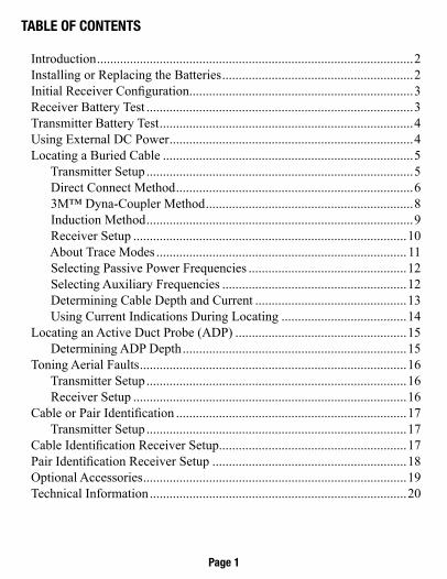
Table of ConTenTs
Introduction ................................................................................................2Installing or Replacing the Batteries ..........................................................2Initial Receiver Configuration ....................................................................3Receiver Battery Test .................................................................................3Transmitter Battery Test .............................................................................4Using External DC Power ..........................................................................4Locating a Buried Cable ............................................................................5 Transmitter Setup .................................................................................5 Direct Connect Method ........................................................................6 3M™ Dyna-Coupler Method ...............................................................8 Induction Method .................................................................................9 Receiver Setup ...................................................................................10 About Trace Modes ............................................................................ 11 Selecting Passive Power Frequencies ................................................12 Selecting Auxiliary Frequencies ........................................................12 Determining Cable Depth and Current ..............................................13 Using Current Indications During Locating ......................................14Locating an Active Duct Probe (ADP) ....................................................15 Determining ADP Depth ....................................................................15 Toning Aerial Faults .................................................................................16 Transmitter Setup ...............................................................................16 Receiver Setup ...................................................................................16Cable or Pair Identification ......................................................................17 Transmitter Setup ...............................................................................17Cable Identification Receiver Setup .........................................................17Pair Identification Receiver Setup ...........................................................18Optional Accessories ................................................................................19Technical Information ..............................................................................20
Page 1
InTroduCTIonThe 3M™ Dynatel™ Advanced Cable Locator 2250 consists of a Transmit-ter and a Receiver for locating buried cables or Active Duct Probes (sondes). It also measures and pinpoints conductor faults in aerial cables. The Transmitter provides four frequencies to accommodate varying factors such as distance, cable type, or soil conditions. If desired, all four frequencies may be transmitted at once. The Transmitter also provides a separate Tone function for identifying cables and pairs. The Receiver provides four locat-ing modes to accomplish fast or difficult tracing and to pinpoint or verify a buried cable. The Receiver detects 50 or 60 Hz AC Power signals and also measures the signal current in a cable and displays its magnitude. The depth of buried cables or sondes may also be displayed.
Note: For more detailed locating instructions and advanced locating techniques, ask your 3M sales representative or call 800/200-0265 for a free publication called Cable and Pipe Locating Techniques.
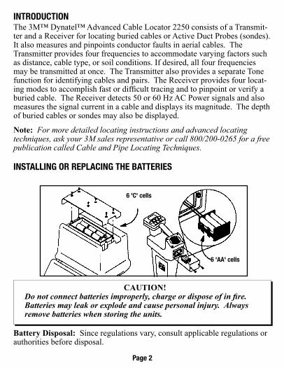
InsTallIng or rePlaCIng The baTTerIes
Battery Disposal: Since regulations vary, consult applicable regulations or authorities before disposal.
6 'C' cells
6 'aa' cells
CautioN! Do not connect batteries improperly, charge or dispose of in fire. Batteries may leak or explode and cause personal injury. Always remove batteries when storing the units.
Page 2
InITIal reCeIver ConfIguraTIonDisplay depth units (inches, feet and inches, or centimeters) may be changed while holding and pressing . For each press, one of three units will display. To change the passive Power frequency, press and hold then press to toggle between 50 or 60 Hz as displayed in the lower left corner of the display.To change the Null bar graph display mode, press and hold then press to toggle between normal Null bar graph display (Null flag will flash) and inverse Null bar graph display (Null flag is solid). See section About Trace Modes (Page 11) for further information.
Page 3
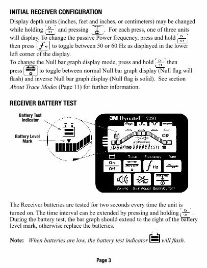
reCeIver baTTery TesT
The Receiver batteries are tested for two seconds every time the unit is turned on. The time interval can be extended by pressing and holding . During the battery test, the bar graph should extend to the right of the battery level mark, otherwise replace the batteries.
Note: When batteries are low, the battery test indicator will flash.
battery Test Indicator
battery level Mark
TransMITTer baTTery TesT
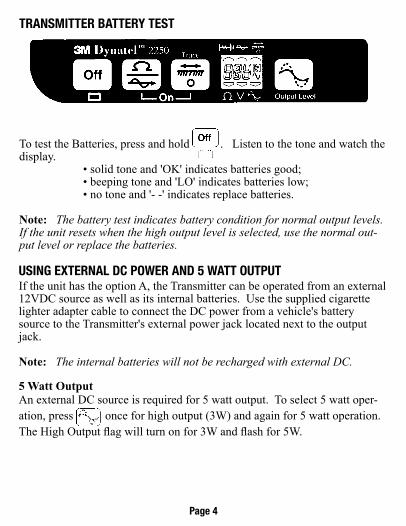
To test the Batteries, press and hold . Listen to the tone and watch the display. • solid tone and 'OK' indicates batteries good; • beeping tone and 'LO' indicates batteries low; • no tone and '- -' indicates replace batteries.
Note: The battery test indicates battery condition for normal output levels. If the unit resets when the high output level is selected, use the normal out-put level or replace the batteries.
usIng exTernal dC Power and 5 waTT ouTPuTIf the unit has the option A, the Transmitter can be operated from an external 12VDC source as well as its internal batteries. Use the supplied cigarette lighter adapter cable to connect the DC power from a vehicle's battery source to the Transmitter's external power jack located next to the output jack. Note: The internal batteries will not be recharged with external DC.
5 Watt outputAn external DC source is required for 5 watt output. To select 5 watt oper-ation, press once for high output (3W) and again for 5 watt operation. The High Output flag will turn on for 3W and flash for 5W.
Page 4
loCaTIng a burIed CableTransmitter setup
Perform a battery test and then connect the Transmitter using one of the three methods below to put tracing signal on a cable.
Note: Key descriptions can be found inside the Transmitter lid.
DaNger!Voltage greater than 240 volts will damage equipment and cause personal injury and death. Make all direct test connections before turning on the Transmitter. Then activate the Transmitter in the Ohms mode and check the display for voltage readings. Follow standard procedures for reducing the voltage.
WarNiNg!Potential for electrical shock exists when handling connecting cables while the Transmitter is in the TRACE, FAULT or TONE modes. Turn the Transmitter off before handling connecting cables.
Page 5
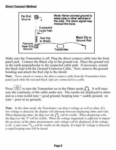
Make sure the Transmitter is off. Plug the direct connect cable into the front panel jack. Connect the Black clip to the ground rod. Place the ground rod in the earth perpendicular to the suspected cable path. If necessary, extend the black lead with the Ground Extension Cable. Next, remove the ground bonding and attach the Red clip to the shield.
Press to turn the Transmitter on in the Ohms mode . It will mea-sure the continuity of the cable under test. The results are displayed in ohms and as a tone (solid tone = good ground; beeping tone = usable ground; no tone = poor or no ground).
Note: In the ohms mode, the Transmitter can detect voltage as well as ohms. If a low voltage is detected, the display will alternate between displaying ohms and volts. When displaying ohms, the flag over the will be visible. When displaying volts, the flag over the 'V' will be visible. When the voltage magnitude is sufficient to impair the accuracy of the ohms measurement, only voltage will be displayed. If the voltage is AC, a sine wave will be visible on the display. If a high AC voltage is detected, a rapid beeping tone will be heard.
Note: Never attach or remove the direct connect cable from the Transmitter front panel jack while the red and black clips are connected to a cable.
direct Connect Method
Page 6
Press to select Trace mode. Press again to select one or all of the four frequencies. The display will alternate between displaying the selected frequency and the output signal current. It is best to choose the lowest frequency for direct connect with far-end ground and a high frequency for direct connect with no far-end ground.
Press to select high output level for longer tracing distances and deep cables.
Transmitter setup is finished, now go to LoCatiNg a BurieD CaBLe - ReceiveR Setup (Page 10).
Page 7
3M™ dyna-Coupler Method
Cable Path
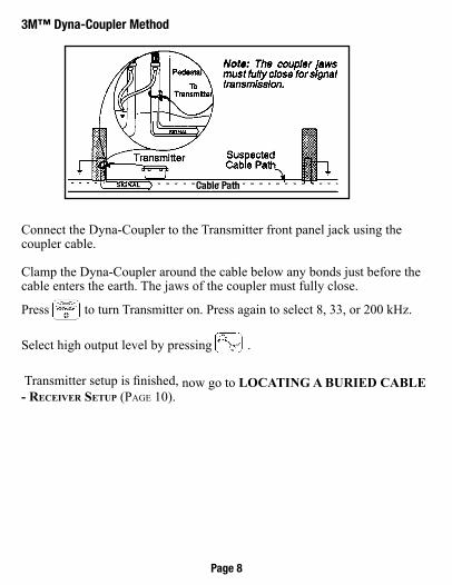
Connect the Dyna-Coupler to the Transmitter front panel jack using the coupler cable.
Clamp the Dyna-Coupler around the cable below any bonds just before the cable enters the earth. The jaws of the coupler must fully close.
Press to turn Transmitter on. Press again to select 8, 33, or 200 kHz.
Select high output level by pressing .
Transmitter setup is finished, now go to LoCatiNg a BurieD CaBLe - ReceiveR Setup (Page 10).
Page 8
Induction Method
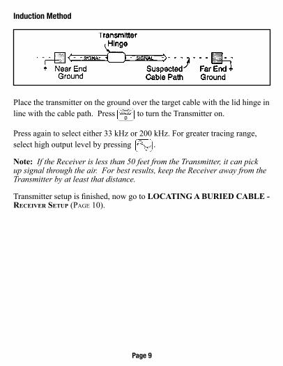
Place the transmitter on the ground over the target cable with the lid hinge in line with the cable path. Press to turn the Transmitter on.
Press again to select either 33 kHz or 200 kHz. For greater tracing range, select high output level by pressing .
Note: If the Receiver is less than 50 feet from the Transmitter, it can pick up signal through the air. For best results, keep the Receiver away from the Transmitter by at least that distance.
Transmitter setup is finished, now go to LoCatiNg a BurieD CaBLe - ReceiveR Setup (Page 10).
Page 9
loCaTIng a burIed Cablereceiver setup
Note: Key descriptions can be found on the side of the Receiver.
Press to turn the Receiver on.
Press to select the power frequency (see section on Selecting Passive Power Frequencies on Page 12) for passive locating; otherwise, select the same frequency as the Transmitter.
Press to adjust the speaker volume as needed: off, normal, high, or high-expanded. The high-expanded setting causes the audio to cut off below a certain threshold.
Press to select a locate mode (Peak , Null , or Diff ). To select Special Peak mode: from Peak mode, press and hold then press to toggle between Peak and Special Peak modes. While in Special Peak mode, the peak flag will flash.
Note: Peak, Special Peak, or Null mode may require re-setting the Receiver gain. Press when the bar graph remains either fully open or fully closed. This is not necessary in differential mode since the unit automatically adjusts the receiver gain.
Page 10
about Trace Modes
Peak: In this mode, as the antenna crosses the cable, the Receiver speaker volume increases to a maximum and the bar graph fills from both sides toward the middle. As the antenna moves off the cable path, the speaker volume decreases and the bar graph opens.
Peak with High-expanded: While in Peak mode, press to select High-Expanded (the highest setting). Speaker response is cut off as the antenna moves away from the cable.Null: In this mode, the signal is a minimum directly over the cable and is maximum on either side of the cable. The speaker volume and display sig-nal strength correspond to the signal being received. In the normal bar graph display mode (Null flag flashing) the bar graph opens at low signal strength and closes at high signal strength. In the inverse Null bar graph display mode (Null flag is on solid), the bar graph closes at low signal strength and opens at high signal strength.Differential: In this mode, the Receiver provides an indication of the rela-tive position of the cable to the Receiver by displaying right or left arrows (the arrow points toward the cable). The bar graph increases to a maximum as the Receiver antenna is moved directly over the cable path. Speaker re-sponse is a high warbling tone to the right of the cable path, a low warbling tone to the left, and a solid tone directly over the cable. Special Peak Mode: This mode will increase the signal sensitivity of the Receiver when the signal is too weak for normal tracing. Use special atten-tion when using this mode because it is more susceptible to congestion than the normal peak mode. Numerical Signal Strength Display resolution: The user may select be-tween 3 levels of signal strength resolution. The setting will be displayed on the right end of the bar graph during selection.To change the setting, press
and hold the key during power up then press the key. Display resolution may be changed between the standard 1X, (no bars illuminated), 2X, (One bar illuminated), and 4X (Two bars illuminated). The unit saves the last setting until changed. Note: While tracing cables, keep the Receiver handle in line with the sus-pected cable path.
Page 11
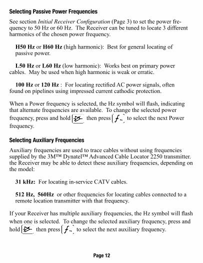
selecting Passive Power frequencies
See section Initial Receiver Configuration (Page 3) to set the power fre-quency to 50 Hz or 60 Hz. The Receiver can be tuned to locate 3 different harmonics of the chosen power frequency.
H50 Hz or H60 Hz (high harmonic): Best for general locating of passive power.
L50 Hz or L60 Hz (low harmonic): Works best on primary power cables. May be used when high harmonic is weak or erratic.
100 Hz or 120 Hz : For locating rectified AC power signals, often found on pipelines using impressed current cathodic protection.
When a Power frequency is selected, the Hz symbol will flash, indicating that alternate frequencies are available. To change the selected power frequency, press and hold then press to select the next Power frequency.
selecting auxiliary frequencies
Auxiliary frequencies are used to trace cables without using frequencies supplied by the 3M™ Dynatel™ Advanced Cable Locator 2250 transmitter. the Receiver may be able to detect these auxiliary frequencies, depending on the model:
31 kHz: For locating in-service CATV cables.
512 Hz, 560Hz or other frequencies for locating cables connected to a remote location transmitter with that frequency.
If your Receiver has multiple auxiliary frequencies, the Hz symbol will flash when one is selected. To change the selected auxiliary frequency, press and hold then press to select the next auxiliary frequency.
Page 12
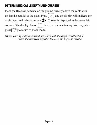
deTerMInIng Cable dePTh and CurrenT
Place the Receiver Antenna on the ground directly above the cable with
the handle parallel to the path. Press and the display will indicate the
cable depth and relative current . Current is displayed in the lower left
corner of the display. Press twice to continue tracing. You may also
press to return to Trace mode.
Note: During a depth-current measurement, the display will exhibit ' – – – ' when the received signal is too low, too high, or erratic.
Page 13
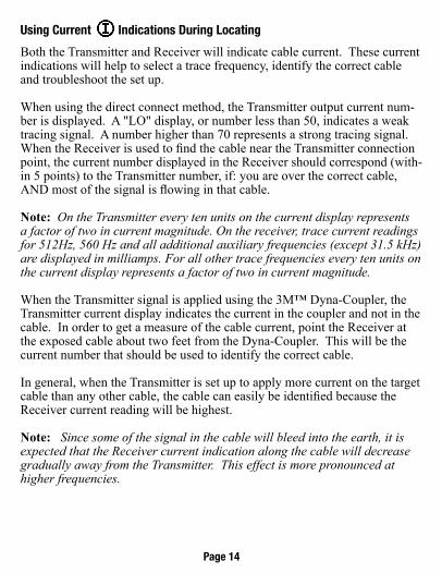
using Current Indications during locating
Both the Transmitter and Receiver will indicate cable current. These current indications will help to select a trace frequency, identify the correct cable and troubleshoot the set up.
When using the direct connect method, the Transmitter output current num-ber is displayed. A "LO" display, or number less than 50, indicates a weak tracing signal. A number higher than 70 represents a strong tracing signal. When the Receiver is used to find the cable near the Transmitter connection point, the current number displayed in the Receiver should correspond (with-in 5 points) to the Transmitter number, if: you are over the correct cable, AND most of the signal is flowing in that cable.
Note: On the Transmitter every ten units on the current display represents a factor of two in current magnitude. On the receiver, trace current readings for 512Hz, 560 Hz and all additional auxiliary frequencies (except 31.5 kHz) are displayed in milliamps. For all other trace frequencies every ten units on the current display represents a factor of two in current magnitude.
When the Transmitter signal is applied using the 3M™ Dyna-Coupler, the Transmitter current display indicates the current in the coupler and not in the cable. In order to get a measure of the cable current, point the Receiver at the exposed cable about two feet from the Dyna-Coupler. This will be the current number that should be used to identify the correct cable.
In general, when the Transmitter is set up to apply more current on the target cable than any other cable, the cable can easily be identified because the Receiver current reading will be highest.
Note: Since some of the signal in the cable will bleed into the earth, it is expected that the Receiver current indication along the cable will decrease gradually away from the Transmitter. This effect is more pronounced at higher frequencies.
Page 14
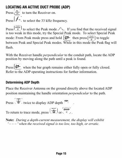
loCaTIng an aCTIve duCT Probe (adP)Press to turn the Receiver on.
Press to select the 33 kHz frequency.
Press to select the Peak mode . If you find that the received signal is too weak in this mode, try the Special Peak mode. To select Special Peak mode: From Peak mode press and hold then press to toggle between Peak and Special Peak modes. While in this mode the Peak flag will flash.
With the Receiver handle perpendicular to the conduit path, locate the ADP position by moving along the path until a peak is found.
Press when the bar graph remains either fully open or fully closed. Refer to the ADP operating instructions for further information.
determining adP depth
Place the Receiver Antenna on the ground directly above the located ADP position maintaining the handle orientation perpendicular to the path.
Press twice to display ADP depth . To return to trace mode, press or .
Note: During a depth-current measurement, the display will exhibit ' – – – ' when the received signal is too low, too high, or erratic.
Page 15
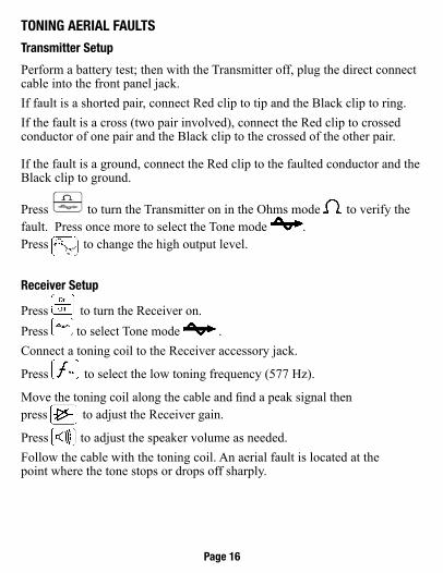
TonIng aerIal faulTs
Transmitter setup
Perform a battery test; then with the Transmitter off, plug the direct connect cable into the front panel jack.If fault is a shorted pair, connect Red clip to tip and the Black clip to ring.If the fault is a cross (two pair involved), connect the Red clip to crossed conductor of one pair and the Black clip to the crossed of the other pair.
If the fault is a ground, connect the Red clip to the faulted conductor and the Black clip to ground.
Press to turn the Transmitter on in the Ohms mode to verify the fault. Press once more to select the Tone mode . Press to change the high output level.
receiver setup
Press to turn the Receiver on. Press to select Tone mode .Connect a toning coil to the Receiver accessory jack.
Press to select the low toning frequency (577 Hz).
Move the toning coil along the cable and find a peak signal then press to adjust the Receiver gain.
Press to adjust the speaker volume as needed. Follow the cable with the toning coil. An aerial fault is located at the point where the tone stops or drops off sharply.
Page 16
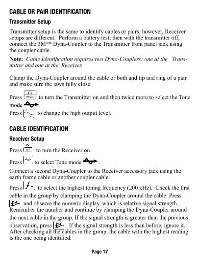
Cable or PaIr IdenTIfICaTIon
Transmitter setup
Transmitter setup is the same to identify cables or pairs, however, Receiver setups are different. Perform a battery test; then with the transmitter off, connect the 3M™ Dyna-Coupler to the Transmitter front panel jack using the coupler cable. Note: Cable Identification requires two Dyna-Couplers: one at the Trans-mitter and one at the Receiver.
Clamp the Dyna-Coupler around the cable or both and tip and ring of a pair and make sure the jaws fully close.
Press to turn the Transmitter on and then twice more to select the Tone mode . Press to change the high output level.
Cable IdenTIfICaTIon
receiver setup
Press to turn the Receiver on.
Press to select Tone mode .Connect a second Dyna-Coupler to the Receiver accessory jack using the earth frame cable or another coupler cable.
Press to select the highest toning frequency (200 kHz). Check the first cable in the group by clamping the Dyna-Coupler around the cable. Press
and observe the numeric display, which is relative signal strength. Remember the number and continue by clamping the Dyna-Coupler around the next cable in the group. If the signal strength is greater than the previous observation, press . If the signal strength is less than before, ignore it. After checking all the cables in the group, the cable with the highest reading is the one being identified.
Page 17
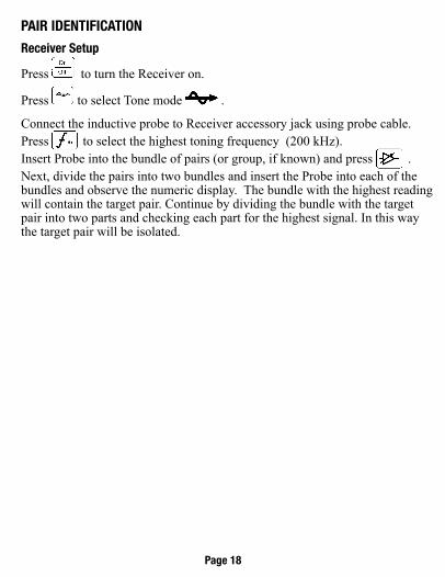
PaIr IdenTIfICaTIon
receiver setup
Press to turn the Receiver on.
Press to select Tone mode .
Connect the inductive probe to Receiver accessory jack using probe cable.Press to select the highest toning frequency (200 kHz).Insert Probe into the bundle of pairs (or group, if known) and press . Next, divide the pairs into two bundles and insert the Probe into each of the bundles and observe the numeric display. The bundle with the highest reading will contain the target pair. Continue by dividing the bundle with the target pair into two parts and checking each part for the highest signal. In this way the target pair will be isolated.
Page 18
oPTIonal 3M™ eleCTronIC MarkIng sysTeM (eMs) aCCessorIes
3M™ 6" Dyna-Coupler with Pouch, 1196 3M™ Soft Carrying Bag 2200 Series 3M™ 4.5" Dyna-Coupler 4001 3M™ Dynatel Locator Coupler Accessory Kit 4519 3M™ Cable Locator Coupler Accessory Kit 3019 3M™ ADP 33KHZ Sonder for use with Dynatel Series Locators 3229 3M™ Coupler Cable 9011 3M™ Ground Extension Cable 9043
Page 19
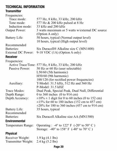
TeChnICal InforMaTIonTransmitterFrequencies: Trace mode: 577 Hz, 8 kHz, 33 kHz, 200 kHz Tone mode: 577 Hz & 200 kHz pulsed at 8 Hz Induction mode: 33 kHz and 200 kHzOutput Power: 3 watts maximum or 5 watts w/external DC source (Option A only)Battery Life: 50 hours, typical (Normal output level) 10 hours, typical (High output level)Recommended Batteries: Six Duracell® Alkaline size C (MN1400)External DC Power: 9-18 VDC (1A) (Option A only)receiverFrequencies: Active Trace/Tone: 577 Hz, 8 kHz, 33 kHz, 200 kHz Passive Power: 50 Hz or 60 Hz (user selectable) L50/60 (5th harmonic) H50/60 (9th harmonic) 100/120 (for rectified power frequencies) Auxiliary: T-Model: 31.5 kHz, 512 Hz and 560 Hz P-Model: 31.5 kHZTrace Modes: Dual Peak, Special Peak, Dual Null, DifferentialDepth Range: 0 to 360 inches (0 to 914 cm)Depth Accuracy: ±10% ± 1 digit for 0 to 60 inches (0 to 152 cm) ±15% for 60 to 180 inches (152 cm to 457 cm) ±20% for 180 to 360 inches (457 cm to 914 cm)Battery Life: 35 hours, typical Recommended Batteries: Six Duracell Alkaline size AA (MN1500) environmentalTemperature Range: Operating : -4° to 122° F (-20° to 50° C ) Storage: -40° to 158° F (-40° to 70° C ) PhysicalReceiver Weight: 1.9 kg (4.1 lbs)Transmitter Weight: 2.4 kg (5.2 lbs)
Page 20

Page 22
Notes
3M and Dynatel are registered trademarks of 3M Company.Duracell® is a registered trademark of Duracell Inc.
This is the EU symbol for equipment that is covered under the Waste from Electrical and Electronic Equipment (WEEE) directive per CENELEC Speci�cation 5041. It indicates that certain products should not be discarded in the trash, but rather should be recycled. This applies to all electronic pluggable and battery powered products.
Important noticeAll statements, technical information and recommendations related to 3M Products are based on information believed to be reliable, but the accuracy or completeness is not guaranteed. Before using the 3M Product, you must evaluate it and determine if it is suitable for your intended application. Because conditions of Product use are outside of our control and vary widely you assume all risks and liability associated with such use. Any Product-related statements not contained in current 3M publications, or any contrary statements contained in your purchase order, shall have no force or effect unless expressly agreed to in writing by an authorized officer of 3M.
limited Product warranty 3M Locators (except accessories), will conform to 3M’s published specifications and will be free from defects in material and manufacture for a period of twelve (12) months from the date of purchase. Dry cell batteries included in any of 3M’s products are warranted only to the extent the battery manufacturer determines such batteries are covered by its warranty. Locating accessories are warranted for ninety (90) days after purchase. 3M’s obligations and liability under this warranty are limited to repairing, replacing or refund of the purchase price, at 3M’s option, any of 3M’s products which, after normal and proper usage, are determined by 3M to be defective. This warranty does not extend to any of 3M’s products which have been subjected to misuse, neglect, accident or improper applications, nor shall it extend to products which have been repaired or substantially altered outside 3M’s manufacturing or repair facility, nor to any associated instruments, equipment or apparatus. Before utilizing any of 3M’s products, BUYER should determine the suitability of the product for BUYER'S intended use. 3M Makes no oTher warranTIes, exPressed or IMPlIed, InCludIng any IMPlIed warranTIes of MerChanTabIlITy or fITness for a ParTICular PurPose. In no case shall 3M be liable for any special, incidental, or consequential damages based upon breach of warranty, breach of contract, negligence, strict liability or any other legal theory. This limitation does not apply to claims for personal injury. Special Condition: Shipments into authorized distributor/supplier locations will have an additional ninety (90) day warranty period
3
electrical Market division6801 River Place Blvd.Austin, TX 78726-9000800-200-0265FAX: 877-601-1305www.3M.com/dynatel
Please Recycle. Printed in USA.© 3M 2014. All Rights Reserved.78-8097-6518-9 Rev D


![3M Dynatel Advanced Pipe/Cable Locator 2220Mmultimedia.3m.com/mws/media/536386O/3mtm-dynateltm-advance… · Direct Connect Cable (Utility size clip 5/8" [15 .8 mm]) 4 .5" (114 mm)](https://static.fdocuments.in/doc/165x107/5eb986d98f1407583b418663/3m-dynatel-advanced-pipecable-locator-2220mmultimedia3mcommwsmedia536386o3mtm-dynateltm-advance.jpg)