3M™ Detection System Model 3500...
19
3M™ Detection System Model 3500 Series Architect/Contractor Information Package
Transcript of 3M™ Detection System Model 3500...

3M™ Detection System Model 3500 Series
Architect/Contractor Information Package

Copyright 3M, 2014. All rights reserved.
3M™ Detection System Model 3500 Architect/Contractor Information Package, 78-8123-7861-6C5
3M is a trademark of 3M.
The original instructions in this document were written in U.S. English. All other languages are a translation of the original instructions.
Detection System Model 3500 Architect/Contractor Information Package
Table of Contents
A letter from 3M Library Systems........................................................................................................................4
Pre-installation worksheet....................................................................................................................................5Contact information.............................................................................................................................................5Ordering information...........................................................................................................................................5Layout information...............................................................................................................................................5
Introduction............................................................................................................................................................6Using this architect/contractor information package..........................................................................................6Introducing the 3M™ Detection System Model 3500 Series.............................................................................6Mounting and lattice-to-lattice wiring options.....................................................................................................7System configurations.........................................................................................................................................7System options....................................................................................................................................................7Detection zone....................................................................................................................................................7System weight.....................................................................................................................................................7
Implementation responsibilities..........................................................................................................................8
Facility requirements.............................................................................................................................................9Module dimensions.............................................................................................................................................9System dimensions...........................................................................................................................................11System placement.............................................................................................................................................12Service and interference issues........................................................................................................................12Staff and patron considerations........................................................................................................................13Electronics enclosure requirements.................................................................................................................13Buried cable layout requirements.....................................................................................................................14Positioning two systems together ....................................................................................................................17Direct mount and buried cable floor requirements...........................................................................................17Environmental requirements.............................................................................................................................17Electrical requirements.....................................................................................................................................17
Warranty................................................................................................................................................................18
3M Service............................................................................................................................................................19Information to gather.........................................................................................................................................193M Service phone numbers..............................................................................................................................193M Library Systems Web Site..........................................................................................................................19
78-8123-7861-6C5 © 3M, 2014. All rights reserved. 3

Detection System Model 3500 Architect/Contractor Information Package
A letter from 3M Library Systems
78-8123-7861-6C5 © 3M, 2014. All rights reserved. 4

Detection System Model 3500 Architect/Contractor Information Package
Pre-installation worksheetPlease complete this form and fax it to 3M at 1–800–795–9091.
Contact informationUse this section of the form to provide contact information.
Today’s Date _____________________
Sales Consultant ___________________
Key Contact ____________ Phone ______________
Install Location __________Install Date __________
Install Contact ___________ Phone ______________
Purchasing/Payment Contact ___________________
Ordering information
Detection system model _______________________
Mounting option
Accessories _________________________________
Delayed warranty start date (if applicable) _________
Who removes/dismantles old system?3M ___ Cust ___
Model & serial number of equipment to be removed or replaced _______________________
Pre–installation worksheet reviewer ______________
PO required for invoice payment? Yes ___ No ___
Layout informationUse this section of the form to sketch a layout for thesystem. Ensure that the space allocated for the system issufficient, which includes the requirements listed in Facilityrequirements on page 9.
78-8123-7861-6C5 © 3M, 2014. All rights reserved. 5
Direct mount
Baseplate Buriedcable
DT_Mounting_Options

Detection System Model 3500 Architect/Contractor Information Package
Introduction
Using this architect/contractor information packageThis package provides architects and contractors with information necessary to prepare the site for the detectionsystem installation. The information provided here must be followed to ensure optimal performance.
Before beginning new construction or changing an existing structure, contact 3M Library Systems TechnicalService at 1-800-328-0067 (website: http://www.3M.com/library) or your sales representative to:
• Confirm that you have the most recent version of this document.
• Verify that the proposed system can be installed in the planned space.
Introducing the 3M™ Detection System Model 3500 Series
Key features
The 3M™ Detection System Model 3500 Series assists in preventingunauthorized removal of a library’s materials when items are marked with3M Tattle-Tape™ strips. System features include:
• 36 in. [91,4 cm] corridor width that complies with ADA (Americanswith Disabilities Act) guidelines
• Complete safety for magnetic media
• Integrated audio and visual alarms that alert staff when a secured itemis detected
• Selectable vertical detection zone:
Floor to 62 in. [157,5 cm]
8 in. to 70 in. [20,3 to 177,8 cm] (recommended)
• Patron counter that automatically tallies the number of customerspassing through the detection system
• Fits a variety of library decors
• Equipped with auxiliary contacts for signaling remote devices, such as camera systems
• Single- and dual-corridor configurations
78-8123-7861-6C5 © 3M, 2014. All rights reserved. 6

Detection System Model 3500 Architect/Contractor Information Package
Mounting and lattice-to-lattice wiring optionsThe detection system supports the followingmounting and wiring options:
• Direct mount, with lattices mounted to thefloor and lattice-to-lattice wiring routedthrough a floor-mounted threshold wireway
• Buried cable, with lattices mounted to the floorand lattice-to-lattice wiring routed beneath thefloor in electrical conduit
• Baseplate, with lattices mounted to a baseplateand lattice-to-lattice wiring routed through thebaseplate
System configurationsThe Detection System Model 3500 Series canbe configured as a single- or dual-corridorsystem.
System options
• CCTV monitor
• Voice alarm
Detection zoneThe primary zone of detection between Model3500 Series lattices extends 6 in. [15 cm] abovethe surface of the floor to 72 in. [1,82 m] abovethe floor. The electronic coverage in this zone isnot 100%, but the rate of detection is effectiveto deter the loss of protected materials.
System weight
• Model 3501: 210 lb. [95 Kg]
• Model 3502: 300 lb. [136 Kg]
78-8123-7861-6C5 © 3M, 2014. All rights reserved. 7
Direct Mount Buried Cable Baseplate
3500 mounting options
3500 Configurations

Detection System Model 3500 Architect/Contractor Information Package
Implementation responsibilitiesUse this section to identify system implementation responsibilities.
Responsible party Task When to complete
Architect/contractor
Complete the pre-installation checklist (see Pre-installation worksheet on page 5.) using the information provided in Facility requirements on page 9.
Before construction work begins.
If the site plans a buried cable system, schedule a pre-installation visit (called a Buried Cable Pre-Site Visit) with a 3M technician so that the site can be inspected to ensure location suitability and proper placement of buried conduit.
This step is extremely important! A 3M technician must inspect the site before construction begins. Failure to complete this step may result in costly rework.
Before construction work begins.
3M-trained technician
If the site plans a buried cable system, inspect the planned location to determine suitability.
Before construction work begins.
Architect/contractor
Prepare the site for the detection system in compliance with local codes andthe information provided in Facility requirements on page 9.
Before the 3M technician arrives.
Move system cartons to within 10 feet [3 m] of the installation site. Before the 3M technician arrives.
3M-trained technician
Install the system. On the scheduled installation date.
78-8123-7861-6C5 © 3M, 2014. All rights reserved. 8

Detection System Model 3500 Architect/Contractor Information Package
Facility requirements
Module dimensions
Lattice dimensions Electronics enclosure dimensions
Threshold wireway dimensions Mounting foot dimensions
78-8123-7861-6C5 © 3M, 2014. All rights reserved. 9
70 in. [178 cm]
3.5 in.[89 mm]
25.5 in.[64,8 cm]
3500 lattice dimensions
0.50 in.[1,3 cm]
4.00 in.[10,2 cm]
36 in.[91.4 cm]
3500 Wireway dim
12.4 in.[315 mm]
8.5 in.[216 mm]
11.625 in.[296 mm]
3500 enclosure dimensions
3.45 in.[8,76 cm]
0.84 in.[2,13 cm][64,8 cm]
3500 Mounting Foot dims
0.875 in. [2,2 cm]pin height
Detection System Model 3500 Architect/Contractor Information Package
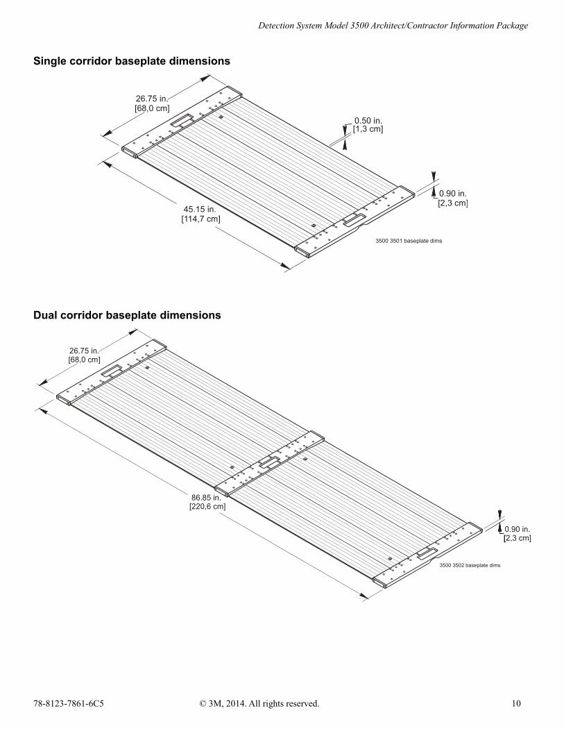
Single corridor baseplate dimensions
Dual corridor baseplate dimensions
78-8123-7861-6C5 © 3M, 2014. All rights reserved. 10
0.90 in.[2,3 cm]
26.75 in.[68,0 cm]
45.15 in.[114,7 cm]
3500 3501 baseplate dims
0.50 in.[1,3 cm]
0.90 in.[2,3 cm]
26.75 in.[68,0 cm]
86.85 in.[220,6 cm]
3500 3502 baseplate dims
[

Detection System Model 3500 Architect/Contractor Information Package
System dimensionsThis section describes the space required for the system itself. Additional space will be required for the following
• To service the system
• To avoid interference from metal objects and other electronic equipment
• To meet the needs of the staff and patrons
See System placement on page 12 for information on these issues.
78-8123-7861-6C5 © 3M, 2014. All rights reserved. 11
36 in.[91 cm]
36 in.[91 cm]
43 in.[109 cm]
82.5 in.[210 cm]
1-Corridor System
2-Corridor System
3.5 in.[8,9 cm]
70 in[178 cm]
3500 Space Requirements
Detection System Model 3500 Architect/Contractor Information Package
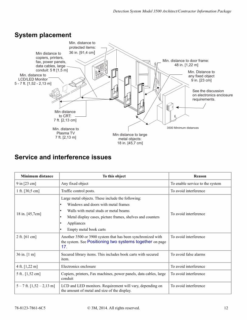
System placement
Service and interference issues
Minimum distance To this object Reason
9 in [23 cm] Any fixed object To enable service to the system
1 ft. [30,5 cm] Traffic control posts. To avoid interference
18 in. [45,7cm]
Large metal objects. These include the following:
• Windows and doors with metal frames
• Walls with metal studs or metal beams
• Metal display cases, picture frames, shelves and counters
• Appliances
• Empty metal book carts
To avoid interference
2 ft. [61 cm] Another 3500 or 3900 system that has been synchronized with the system. See Positioning two systems together on page17.
To avoid interference
36 in. [1 m] Secured library items. This includes book carts with secured item.
To avoid false alarms
4 ft. [1,22 m] Electronics enclosure To avoid interference
5 ft.. [1,52 cm] Copiers, printers, Fax machines, power panels, data cables, large conduit
To avoid interference
5 – 7 ft. [1,52 – 2,13 m] LCD and LED monitors. Requirement will vary, depending on the amount of metal and size of the display.
To avoid interference
78-8123-7861-6C5 © 3M, 2014. All rights reserved. 12
Min. distance toprotected items:36 in. [91,4 cm]
Min. distance to door frame:48 in. [1,22 m]
Min. Distance to any fixed object
9 in. [23 cm]
See the discussion on electronics enclosure requirements.
Min distance to copiers, printers, fax, power panels, data cables, largeconduit: 5 ft [1,5 m]
Min distance to large metal objects:
18 in. [45,7 cm]
Min distance to CRT:
7 ft. [2,13 cm]
3500 Minimum distances
Min. distance toLCD/LED Monitor
5 - 7 ft. [1,52 - 2,13 m]
Min. distance toPlasma TV
7 ft. [2,13 m]

Detection System Model 3500 Architect/Contractor Information Package
Minimum distance To this object Reason
7 ft. [2,13 m] Telephone, CRT, plasma TV. To avoid interference
10 ft. [3,05 m]FM stereo receivers. Note: CD, DVD, and tape players are not affected by the detection system.
To avoid interfering with FM 10 ft. [3,05 m] stereo receiver
20 ft. [6,1 m] Other Model 3900 and 3500 systems (unless systems are connected using a sync cable. See Positioning two systems together on page 17.
To avoid interference
Staff and patron considerationsIn addition to avoiding interference, the system placement decision should include the following considerations:
• Visibility and access of checkout personnel to the detection system
• Space to identify and stop patrons before they leave the library when an alarm occurs
• Compliance with ADA guidelines, which specify a minimum distance of 4 feet [1,22 m] from the system to a door
• Space to avoid accidental alarms caused by patrons standing near the detection system with secured items and to eliminate two-way traffic (enter and exit) through system corridors
• Positioning so that patrons are not required to change directions when exiting the library and so they can easily determine how to exit the library
Electronics enclosure requirementsEnsure that the facilities for the electronic enclosuremeet the following requirements:
• Position the electronics enclosure:
At a height of 6 – 27 inches [15,2 – 68,6 cm]if it is mounted in an area with traffic and 6 –60 inches [15,2 – 152,4 cm] if it is located inan area without traffic
Note:The electronics enclosure must not be placed inthe ceiling or floor.
So as to minimize cable runs through a trafficarea
So that lattices can be seen from it (forservice)
So that air flow around it is not restricted
So that it is no closer than 1 ft. [30,5 cm] from a thermostat (to avoid affecting the heating and cooling system)
78-8123-7861-6C5 © 3M, 2014. All rights reserved. 13
Within 10 feet [3 m]
of outlet
Traffic area height: 6 to 27 in [15,2 - 68,6 cm]
Non-traffic area height: 6 to 60 in [15,2 - 152,4 cm]
Max cable run distance to lattice 21 feet [6,4 m]
Min 1.25 in [31,8 mm] I.D. Non-metallic conduit
3500 Electronic Enclosure Req
Min 4 ft. [1,22 m]

Detection System Model 3500 Architect/Contractor Information Package
Within 10 ft. [3,05 m] of an approved power receptacle
A minimum distance of 4 feet [1,22 m] from lattices
A maximum cable-run distance from the lattices of 21 ft. [6,4 m]
• Route the power cable to the system using either a wiremold or conduit. If you use conduit, it must have a minimum inside diameter of 1.25 in [31,8 cm]. 3M strongly recommends non-metallic conduit whenever local codes permit. When metallic conduit must be used, you must ensure that the conduit does not come in contact with any other metal. This includes metal on the detection system itself.
Buried cable layout requirementsThis section consists of the following topics:
• Conduit requirements on page 14
• Buried cable layout dimensions on page 14
• Conduit layout in single-corridor systems on page 15
• Conduit layout in dual-corridor systems on page 16
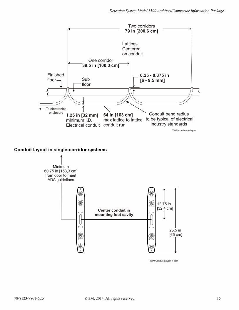
Conduit requirements
The conduit used for cable routing in buried cable systems must meet the following requirements:
• It must have a minimum inside diameter of 1.25 in. [32 mm].
• The lattice to lattice conduit run must not exceed 64 in. [163 cm.].
• The conduit bend radius must be typical of electrical industry standards.
Note:3M strongly recommends non-metallic conduit for buried cable systems whenever local codes permit its use. When metallic conduit must be used, you must ensure that the conduit does not come in contact with any other metal. This includes metal on the detection system itself.
Buried cable layout dimensions
Buried cable installations require the space and conduit specified in the illustration
78-8123-7861-6C5 © 3M, 2014. All rights reserved. 14
Detection System Model 3500 Architect/Contractor Information Package
Conduit layout in single-corridor systems
78-8123-7861-6C5 © 3M, 2014. All rights reserved. 15
Finished floor Sub
floor
1.25 in [32 mm]minimum I.D.Electrical conduit
64 in [163 cm] max lattice to lattice
conduit run
0.25 - 0.375 in[6 - 9,5 mm]
One corridor39.5 in [100,3 cm]
Conduit bend radius to be typical of electrical
industry standards
Two corridors79 in [200,6 cm]
LatticesCentered on conduit
3500 buried cable layout
To electronics enclosure
Center conduit inmounting foot cavity
25.5 in [65 cm]
12.75 in[32,4 cm]
Minimum 60.75 in [153,3 cm]from door to meet
ADA guidelines
3500 Conduit Layout 1 corr
Detection System Model 3500 Architect/Contractor Information Package
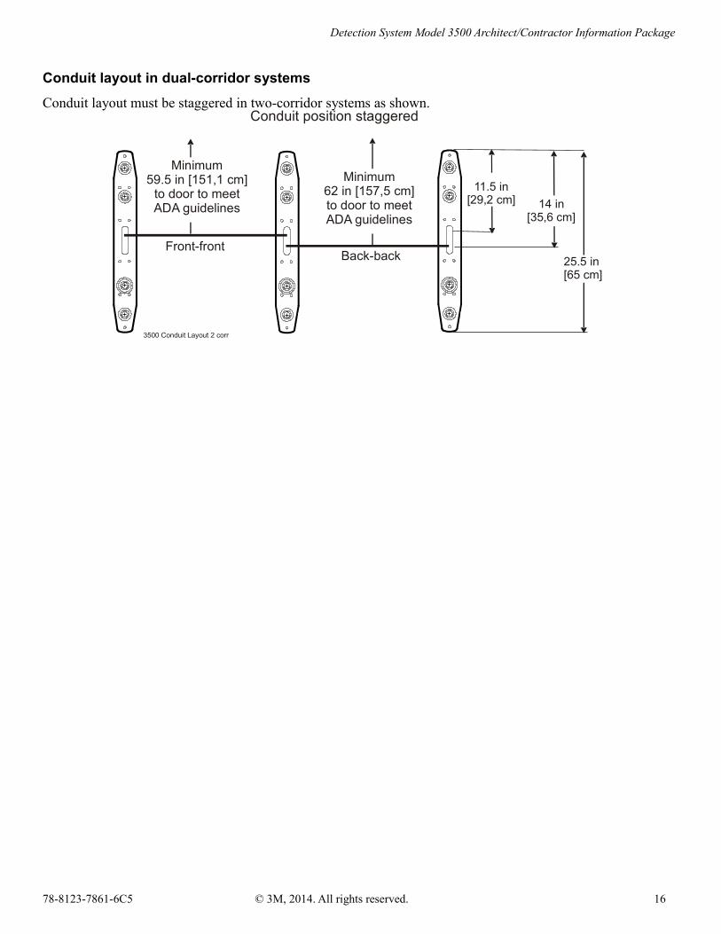
Conduit layout in dual-corridor systems
Conduit layout must be staggered in two-corridor systems as shown.
78-8123-7861-6C5 © 3M, 2014. All rights reserved. 16
11.5 in[29,2 cm]
3500 Conduit Layout 2 corr
Conduit position staggered
Front-frontBack-back
Minimum59.5 in [151,1 cm]
to door to meet ADA guidelines
Minimum62 in [157,5 cm]to door to meet ADA guidelines
25.5 in [65 cm]
14 in [35,6 cm]
Detection System Model 3500 Architect/Contractor Information Package
Positioning two systems together Normally two Model 3500 Detection Systems must be separated by at least 20 feet [6,1 m] to avoid interference. When this isn’t desirable, they can be located a minimum of 24 inches [61 cm] apart if they are connected with a sync cable.
Note:The sync cable runs from the electronics enclosure on one system to the electronics enclosure on the other system and is installed by a 3M technician.
Direct mount and buried cable floor requirementsThe floor to which direct mount and buried cable system are anchored must be:
• A minimum of 3.5 in [8,9 cm] thick and made of flat, high-quality concrete
• Free of reinforcing rod and conduit directly under the mounting foot
Environmental requirements
Operating temperature range 32° F to 122° F
0° C to 50° C
Storage temperature range 40° F to 131° F
- 40° C to 55° C
Humidity 0% to 85 % relative humidity, non-condensing
Electrical requirements3M Detection Systems are sophisticated computer-based devices that require high-quality, surge- and noise-free electrical power for optimum performance. The system is supplied with a 16 gauge, 3-wire, S-rating, 10 ft. long,NEMA 5-15P plug-type power cord. The following are the detection system electrical requirements:
• Single-phase power is required
• Switch selection for voltages from 100 to 240 VAC, 50 or 60Hz.
• Maximum RMS current draw:
100/120 VAC: 2 Amp
210/240 VAC: 1 Amp
• Power receptacle is required at the Electronic Enclosure, within the power-cord length.
• Dedicated circuit is not required but is recommended to prevent overloading and loss of securit
78-8123-7861-6C5 © 3M, 2014. All rights reserved. 17

Detection System Model 3500 Architect/Contractor Information Package
Warranty
78-8123-7861-6C5 © 3M, 2014. All rights reserved. 18

Detection System Model 3500 Architect/Contractor Information Package
3M Service
Information to gatherBefore you call, please have the following information available:
• Name, address, and telephone number of your facility
• Model number(s) of equipment you are calling about —and, if applicable, other equipment installed
• Your question(s), or if applicable, a description of the problem or issue you want addressed
3M Service phone numbersFor questions regarding your system, call one of the following numbers.
In the United States In Canada In other countries
1-800-328-0067 English 1-800-268-6235 Français 1-800-567-3193
Call your local 3M office.
3M Library Systems Web SiteThe 3M Library Systems Web site can be located at http://www.3M.com/library.
For additional information in the United States about 3M Library Systems, go to http://www.3M.com/us/library.
3M Library Systems3M Center, Building 225-4N-14 St. Paul, MN 55144-1000www.3M.com/library
78-8123-7861-6C5 © 3M, 2014. All rights reserved. 19