
3LPP-06_Published Paper
4
3LPP-06 1 Abstract—The placement of a gastro-intestinal feeding tube is a critical procedure for patients in intensive care, especially burn victims. Using traditional non-guided methods, this placement can take up to 15 hours, as X-ray confirmation is needed to make sure that the tube has first cleared the lungs and then entered the intestine via the pyloric valve. Syncro Medical Corporation has developed and patented a magnetically-guided tube using a large, 2.5-kg hand-held permanent magnet which guides a small permanent magnet on the tip of the feeding tube stylet. An electronic reed switch is also used to determine the position of the feeding tube. Using this new process, intestinal feeding tube placement can be accomplished in 15 minutes. Syncro Medical has been working with Youngstown State University to develop a high-temperature superconducting (HTS) electromagnet for this application, as this can be easily turned on and off during the placement procedure. Results from HTS coil testing for Phase I of this project are included in this paper. Index Terms—feeding tube, HTS, electromagnet. I. INTRODUCTION technique for quickly placing post pyloric feeding tubes inside patients have been under development by Syncro Medical based on the initial concept of Dr. Sabry Gabriel [1]. The baseline magnet is a permanent magnet roughly 10 cm in diameter and 4 cm thick, weighing ~2.5 kg including the aluminum packaging. In order to place the feeding tube inside the patient, a wire- guided stylet is placed inside the feeding tube. A small permanent magnet—2.5 mm OD, 0.5 mm ID, 10 mm long—is attached to the tip of the stylet. The large external permanent magnet is used to guide the internal stylet magnet. Once the feeding tube is in the proper position inside the pylorus, the stylet is removed, leaving only the feeding tube in place. A photograph of this magnet is shown in Fig. 1. Manuscript received 9 October 2012. This work was supported in part by the U.S. Department of Defense. J. P. Voccio was with American Superconductor Corp. for most of this work and is now with the MIT Magnet Laboratory. Cambridge, MA ([email protected]). Frank Li and Jalal Jalali are with Youngstown State University, Youngstown, OH 44505. Craig Butrick is a student at Youngstown State University and is now with Lincoln Electric Company, Cleveland, OH. Michael Sammartino and Mike Kovach are students at Youngstown State University. Joe Winkler and Gary Wakeford were with Syncro Medical Corporation, Youngstown Ohio 44505. Fig. 1. Photograph of the baseline Syncro Medical PM magnet. In order to understand the magnetic field profile of the permanent magnet, an ANSYS finite element model was developed. The magnetic flux plot for this magnet is provided in Fig. 2. This magnet produces a magnetic field of 30 mT at a distance of 10 cm from the top surface of the magnet. Therefore, the goal of the ensuing HTS electromagnet is to achieve equal performance of the permanent magnet while minimizing both size and weight. In the meantime, the added benefits of turning on/off the high strength magnetic field are essential for these feeding tube applications. Fig. 2 Axisymmetric magnetic analysis model and flux plot for baseline Syncro permanent magnet (PM). Peak flux density is 0.6 T near permanent magnet and 30 mT 10 cm from magnet surface denoted by black dot. (The PM is denoted by region 1, while area 2 denotes the cross-section for the HTS electromagnet in ensuing analysis.) High-Temperature Superconducting Coil For Magnetically-Guided Feeding Tube Application John Voccio, Frank Li, Jalal Jalali, Mike Kovach, Michael Sammartino, Craig Butrick, Joe Winkler and Gary Wakeford A 1 2
-
Upload
gary-wakeford -
Category
Documents
-
view
165 -
download
0
Transcript of 3LPP-06_Published Paper

3LPP-06
1
Abstract—The placement of a gastro-intestinal feeding tube is
a critical procedure for patients in intensive care, especially burn
victims. Using traditional non-guided methods, this placement
can take up to 15 hours, as X-ray confirmation is needed to make
sure that the tube has first cleared the lungs and then entered the
intestine via the pyloric valve. Syncro Medical Corporation has
developed and patented a magnetically-guided tube using a large,
2.5-kg hand-held permanent magnet which guides a small
permanent magnet on the tip of the feeding tube stylet. An
electronic reed switch is also used to determine the position of the
feeding tube. Using this new process, intestinal feeding tube
placement can be accomplished in 15 minutes. Syncro Medical
has been working with Youngstown State University to develop a
high-temperature superconducting (HTS) electromagnet for this
application, as this can be easily turned on and off during the
placement procedure. Results from HTS coil testing for Phase I
of this project are included in this paper.
Index Terms—feeding tube, HTS, electromagnet.
I. INTRODUCTION
technique for quickly placing post pyloric feeding tubes
inside patients have been under development by Syncro
Medical based on the initial concept of Dr. Sabry Gabriel [1].
The baseline magnet is a permanent magnet roughly 10 cm in
diameter and 4 cm thick, weighing ~2.5 kg including the
aluminum packaging.
In order to place the feeding tube inside the patient, a wire-
guided stylet is placed inside the feeding tube. A small
permanent magnet—2.5 mm OD, 0.5 mm ID, 10 mm long—is
attached to the tip of the stylet. The large external permanent
magnet is used to guide the internal stylet magnet. Once the
feeding tube is in the proper position inside the pylorus, the
stylet is removed, leaving only the feeding tube in place. A
photograph of this magnet is shown in Fig. 1.
Manuscript received 9 October 2012. This work was supported in part by
the U.S. Department of Defense.
J. P. Voccio was with American Superconductor Corp. for most of this
work and is now with the MIT Magnet Laboratory. Cambridge, MA
Frank Li and Jalal Jalali are with Youngstown State University,
Youngstown, OH 44505.
Craig Butrick is a student at Youngstown State University and is now with
Lincoln Electric Company, Cleveland, OH.
Michael Sammartino and Mike Kovach are students at Youngstown State
University.
Joe Winkler and Gary Wakeford were with Syncro Medical Corporation,
Youngstown Ohio 44505.
Fig. 1. Photograph of the baseline Syncro Medical PM magnet.
In order to understand the magnetic field profile of the
permanent magnet, an ANSYS finite element model was
developed. The magnetic flux plot for this magnet is
provided in Fig. 2. This magnet produces a magnetic field of
30 mT at a distance of 10 cm from the top surface of the
magnet. Therefore, the goal of the ensuing HTS electromagnet
is to achieve equal performance of the permanent magnet
while minimizing both size and weight. In the meantime, the
added benefits of turning on/off the high strength magnetic
field are essential for these feeding tube applications.
Fig. 2 Axisymmetric magnetic analysis model and flux plot for baseline
Syncro permanent magnet (PM). Peak flux density is 0.6 T near permanent
magnet and 30 mT 10 cm from magnet surface denoted by black dot. (The
PM is denoted by region 1, while area 2 denotes the cross-section for the HTS
electromagnet in ensuing analysis.)
High-Temperature Superconducting Coil For
Magnetically-Guided Feeding Tube Application
John Voccio, Frank Li, Jalal Jalali, Mike Kovach, Michael Sammartino, Craig Butrick,
Joe Winkler and Gary Wakeford
A
1 2
3LPP-06
2
II. DESIGN
Using the same model shown in Fig. 2, the finite element
analysis for the HTS electromagnet was performed. In this
case, region 1 was modeled as air and current density was
applied to region 2. The novel no-insulation approach to
superconducting magnet design [2] was used for this coil
design. With this approach, the magnet can be made lighter
due to the higher current density. This method allows for
greater packing factor of the HTS wire and also provides self-
protecting capability, as the turns short-out after the current
exceeds the critical current.
In order to explore a wide range of designs, a random
optimization was performed by changing the following
variables:
• Inside Diameter (cm): 5-15
• Outside Diameter (cm): 10-25
• Number of Pancakes: 1-4
• Expected Weight (kg): ~5 (inc. liquid nitrogen)
The results of this analysis are presented in Fig. 3 in terms
of the required coil operating current as a function of the coil
weight. Assuming a bare wire critical current of 100 A at
77 K, the coil critical current needed to be less than 70 A.
Furthermore, designs were screened to minimize both weight
and HTS wire usage. This filtering resulted in the selection
of the Best Designs shown in Table I.
Fig. 3 The operating current vs. weight graph indicates that the best design
weight for the bare (open square) and laminated tapes (solid square) is 0.8 and
1.2 kg, respectively. The bare HTS insert wire has no copper laminate.
III. COIL FABRICATION AND TESTING
Coil 1 was wound with copper-stablized, 2G conductor
from American Superconductor Corporation. This conductor
has a self-field critical current of ~80 Amp. A photograph of
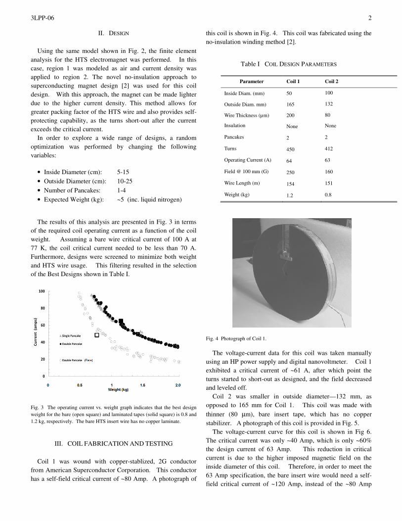
this coil is shown in Fig. 4. This coil was fabricated using the
no-insulation winding method [2].
Table I COIL DESIGN PARAMETERS
Parameter Coil 1 Coil 2
Inside Diam. (mm) 50 100
Outside Diam. mm) 165 132
Wire Thickness (µm) 200 80
Insulation None None
Pancakes 2 2
Turns 450 412
Operating Current (A) 64 63
Field @ 100 mm (G) 250 160
Wire Length (m) 154 151
Weight (kg) 1.2 0.8
Fig. 4 Photograph of Coil 1.
The voltage-current data for this coil was taken manually
using an HP power supply and digital nanovoltmeter. Coil 1
exhibited a critical current of ~61 A, after which point the
turns started to short-out as designed, and the field decreased
and leveled off.
Coil 2 was smaller in outside diameter—132 mm, as
opposed to 165 mm for Coil 1. This coil was made with
thinner (80 µm), bare insert tape, which has no copper
stabilizer. A photograph of this coil is provided in Fig. 5.
The voltage-current curve for this coil is shown in Fig 6.
The critical current was only ~40 Amp, which is only ~60%
the design current of 63 Amp. This reduction in critical
current is due to the higher imposed magnetic field on the
inside diameter of this coil. Therefore, in order to meet the
63 Amp specification, the bare insert wire would need a self-
field critical current of ~120 Amp, instead of the ~80 Amp

3LPP-06
3
current tape used in this coil. This increased level of
performance is feasible with recent improvements in
conductor performance due to thicker YBCO layers—1.2 µm,
instead of only 0.8 µm for the standard tapes.
Fig. 5 Photograph of Coil 2.
Despite the decreased current and field capability, the no-
insulation behavior of this coil is depicted in the data of Fig. 6.
Above the 40 Amp critical current, the measured magnetic
field starts to level out, indicating that the turns are starting to
short out, thereby protecting the coil from burnout.
Fig. 6 Voltage-current curve for 2nd prototype coil, along with field (G)
measured at 10 cm distance.
IV. FORCE MEASUREMENT
While the initial design specification was to create a certain
magnetic field at a distance from the magnet, we came to
realize that creating the force on the stylet permanent magnet
is the real objective. Therefore, in order to establish a
baseline, the stylet magnet was suspended over the larger
permanent magnet via a string, and the attraction force was
measured using a simple spring scale. The results of this
testing showing the force as a function of distance from the
magnet surface is shown in Fig. 7. For a single stylet magnet,
the force at the 10 cm distance is only 20 mN, and the force
was doubled at this distance by adding a second stylet magnet.
As expected, these results show that the force is inversely
proportional to the square of the distance between the two
magnets. Adding a second permanent magnet to the stylet tip
increases the force, but the force is not doubled, as the second
magnet is further away and, therefore, has a lower force
contribution.
In addition, similar testing was performed with a 2T
superconducting magnet. Again, the stylet magnets were
suspended from a string, and the force was measured with a
simple spring scale. Since the superconducting magnet has an
open bore, the force was measured both outside (above the
magnet) and inside the magnet. These results are summarized
in Fig. 8.
0 2.5 5 7.5 10
Distance (cm)
Fig. 7 Results of force measurement.
-15 -10 -5 0 5 10
Distance Above Magnet (cm)
Fig. 8 Force on stylet magnets in vicinity of superconducting magnet.
Interestingly, as the stylet magnets are lowered into the
open bore of the superconducting magnet, the force starts to
level off. This leveling off is due to the uniformity of the
background field; in other words, the field gradient is
decreasing. Therefore, these results indicate that the

3LPP-06
4
attractive force is a function of both the field and the field
gradient.
Furthermore, these results show that one stylet magnet with
the 2T field performs similarly to two stylet magnets at 1T
field. Also, two stylet magnets were tested at the 2T field,
showing twice the force magnitude of the one stylet magnet
test at the same 2T field. Both of these results make intuitive
senses.
In comparing the data from Fig. 7 and Fig. 8, it is
interesting to note that the large permanent magnet, which has
a 600 mT surface field, produces greater forces than the 1T
and 2T superconducting magnet tests, further demonstrating
the need for not only the field strength, but also field gradient.
V. PULSED FORCE MEASUREMENT
A third insulated coil was used for pulsed current testing, in
an effort to reduce the size and weight of the coil. This
double-pancake coil was only 10 cm in diameter and weighed
only 0.5 kg. Compared to the DC current source, the pulsed
current showed a ~30% increase of the dynamic force. In
order to measure dynamic response of the pulsed
electromagnet, the analog output of a Vernier DFS-BTA Force
Sensor was paired with an Agilent MSO6054A oscilloscope
capable of sampling at 500 MHz and recording 4 GSa/s. Peak
results were recorded and measured using the oscilloscope’s
built in functions for maximum precision. Fig. 9 shows the
force measurement (top trace) and current through the
electromagnet (bottom trace). Note that magnetic force is not
instantaneous; it builds over time and is peak right as the
electromagnet is turned off.
Fig. 9. Top curve-output from analog force sensor (500 mV/div); Bottom
signal-current pulse signal (20 Amp/div). Timescale is 2 msec/div.
This method allowed measurements to be taken independent
of frequency, voltage, and control technique. Results were
then precisely compared and validated to find the most
efficient combination.
Additionally, the pulsed electromagnet can have higher
current than that of the DC electromagnet, as long as the off
time is sufficient for the cooling. The high current leads to
higher force and could further reduce the weight of the
electromagnet.
VI. RECOMMENDATIONS FOR FUTURE WORK
As a result of this initial study, the following are
recommendations for further research:
• Investigate coils with higher field gradients,
particularly if they can be made with small outside
diameter.
• Develop cryogenic packaging, including a hand-held
insulated liquid nitrogen container.
VII. CONCLUSION
Light weight HTS electromagnets were demonstrated as a
possible replacement for the permanent magnet currently used
for the Syncro Medical feeding tube application. These coils
used the novel, no-insulation technique, which improves the
coil current density and also greatly enhances the coil stability,
as the turns simply short-out after the critical current is
reached. Future work will be performed on the packaging of
these coils to make a prototype handheld HTS electromagnetic
device for this application.
ACKNOWLEDGMENT
The authors would like to acknowledge the following
people for their help on this project: Linda Waple and Paul
Yankauskas of American Superconductor Corporation; Gary
Wakeford of Syncro Medical; and Nimesh Shrestha of
Youngstown State University.
REFERENCES
[1] S. A. Gabriel; B. McDaniel; D. W. Ashley; M. L. Dalton; T. C.
Gamblin. “Magnetically guided nasoenteral feeding tubes: a new
technique,” The American Surgeon 2001; 67(6):544-9.
[2] Seungyong Hahn, Dong Keun Park, Bascunan, J. Iwasa, Y. of the
Francis Bitter Magnet. Lab., Massachusetts Inst. of Technology,
Cambridge, MA, USA, “HTS Pancake Coils without Turn-to-Turn
Insulation,” IEEE Transactions on Applied Superconductivity, vol. 21,
June 2011, pp. 1592-1595.


![[XLS]eci.nic.ineci.nic.in/delim/paper1to7/TamilNadu.xls · Web viewRev. Dharmapuri & Kanniyakumari Paper 7 Paper 6 Paper 5 Paper 4 Paper 3 Paper 2 Paper 1 Index Tirunelveli (M.Corp.)](https://static.fdocuments.in/doc/165x107/5ad236e17f8b9a86158ce167/xlsecinicinecinicindelimpaper1to7-viewrev-dharmapuri-kanniyakumari-paper.jpg)
