3KXD151800R4501 Advanced Configuration Manual · Advanced Configuration. NOTICE The information in...
42
Industrial IT Asset Master 5.0 Powered by 800xA System Version 5.0 Advanced Configuration
Transcript of 3KXD151800R4501 Advanced Configuration Manual · Advanced Configuration. NOTICE The information in...

IndustrialITAsset Master 5.0
Powered by 800xA System Version 5.0
Advanced Configuration


IndustrialITAsset Master 5.0
Powered by 800xA System Version 5.0
Advanced Configuration
NOTICEThe information in this document is subject to change without notice and should not beconstrued as a commitment by ABB. ABB assumes no responsibility for any errors thatmay appear in this document.
In no event shall ABB be liable for direct, indirect, special, incidental or consequentialdamages of any nature or kind arising from the use of this document, nor shall ABB beliable for incidental or consequential damages arising from use of any software or hard-ware described in this document.
This document and parts thereof must not be reproduced or copied without written per-mission from ABB, and the contents thereof must not be imparted to a third party nor usedfor any unauthorized purpose.
The software or hardware described in this document is furnished under a license andmay be used, copied, or disclosed only in accordance with the terms of such license.
This product meets the requirements specified in EMC Directive 89/336/EEC and in LowVoltage Directive 72/23/EEC.
Copyright © 2003-2007 by ABB. All rights reserved. Release: January 2007Document number: 3KXD151800R4501
TRADEMARKSAll rights to copyrights and trademarks reside with their respective owners.

TABLE OF CONTENTS
About This BookGeneral ..............................................................................................................................7
Document Conventions .....................................................................................................7
Warning, Caution, Information, and Tip Icons..................................................................8
Terminology.......................................................................................................................9
Related Documentation .....................................................................................................9
Additional Information Related to Documentation..............................................10
Section 1 - IntroductionOverview..........................................................................................................................11
Section 2 - Users and SecurityIntroduction .....................................................................................................................13
Installation Engineer ............................................................................................14
Asset Master Service Account .............................................................................15
Maintenance Engineer..........................................................................................15
Maintenance Supervisor & Maintenance Technician...........................................16
Configuration...................................................................................................................17
Creating Windows User Groups and Users..........................................................17
User Roles ............................................................................................................19
User Permissions..................................................................................................21
User Role Bindings and Structure Visibility ........................................................24
Section 3 - Asset Optimization
Section 4 - Device Management & Fieldbuses
3KXD151800R4501 5

Table of Contents
Section 5 - Access Management
Section 6 - OPC Data Access
Section 7 - PC, Network and Software Monitoring
Appendix A - Terminology
6 3KXD151800R4501

About This Book
GeneralThis manual describes the configuration, operation and commissioning of Asset Master including display navigation, device integration for Foundation Fieldbus, PROFIBUS and HART, and asset optimization.
Document ConventionsThe following conventions are used for the presentation of content:
• The words in names of screen elements (for example, the title in the title bar of a window, the label for a field of a dialog box) are initially capitalized.
• Capital letters are used for the name of a keyboard key if it is labeled on the keyboard. For example, press the ENTER key.
• Lowercase letters are used for the name of a keyboard key that is not labeled on the keyboard. For example, the space bar, comma key, and so on.
• Press CTRL+C indicates that you must hold down the CTRL key while pressing the C key (to copy a selected object in this case).
• Press ESC E C indicates that you press and release each key in sequence (to copy a selected object in this case).
• The names of push and toggle buttons are boldfaced. For example, click OK.
• The names of menus and menu items are boldfaced. For example, the File menu.
– The following convention is used for menu operations: MenuName > MenuItem > CascadedMenuItem. For example: select File > New > Type.
3KXD151800R4501 7

Warning, Caution, Information, and Tip Icons About This Book
– The Start menu name always refers to the Start menu on the Windows Task Bar.
• System prompts/messages are shown in the Courier font, and user responses/input are in the boldfaced Courier font. For example, if you enter a value out of range, the following message is displayed:Entered value is not valid. The value must be 0 to 30.
You may be asked to enter the string TIC132 in a field. The string is shown as follows in the procedure:
TIC132
Variables are shown using lowercase letters.
sequence name
Warning, Caution, Information, and Tip IconsThis publication includes Warning, Caution, and Information where appropriate to point out safety related or other important information. It also includes Tip to point out useful hints to the reader. The corresponding symbols should be interpreted as follows:
Electrical warning icon indicates the presence of a hazard which could result in electrical shock.
Warning icon indicates the presence of a hazard which could result in personal injury.
Caution icon indicates important information or warning related to the concept discussed in the text. It might indicate the presence of a hazard which could result in corruption of software or damage to equipment/property.
Information icon alerts the reader to pertinent facts and conditions.
Tip icon indicates advice on, for example, how to design your project or how to use a certain function
8 3KXD151800R4501

About This Book Terminology
Although Warning hazards are related to personal injury, and Caution hazards are associated with equipment or property damage, it should be understood that operation of damaged equipment could, under certain operational conditions, result in degraded process performance leading to personal injury or death. Therefore, fully comply with all Warning and Caution notices.
TerminologyA list of terms associated with Asset Master is provided at Appendix A, Terminology.
Related DocumentationFollowing is a list of documents related to Asset Master.
Title Description
Asset Master 5.0
Installation
This manual descries how to install Asset Master software.
Asset Master 5.0
Basic Configuration and Operation Manual
This manual provides details about basic configuration of Asset Master and basic operations that can be performed with Asset Master.
Industrial Ethernet: A Pocket Guide
Publisher: ISA - The Instrumentation, Systems, and Automation Society, May 2002
ISBN: 1556177887
How to Plan, Install, and Maintain TCP/IP Ethernet Networks: The Basic Reference Guide for Automation and Process Control Engineers.
Foundation Fieldbus: A Pocket Guide
Publisher: ISA - The Instrumentation, Systems, and Automation Society, July 2002
ISBN: 1556177755
Summary of background information, tips, tricks, and items to note when installing, maintaining, or trouble-shooting.
3KXD151800R4501 9

Additional Information Related to Documentation About This Book
Additional Information Related to Documentation
This book refers, at places, to 800xA System documentation and individual product documentation. Consider the following while referring to these documents in the context of Asset Master:
• Ignore all the sections and descriptions referring to 800xA specific configuration and operation. For example:
– Configuration of AC800M controller and its I/O Modules
– User Interfaces like Plant Explorer Workplace, Operator Workplace etc,.
– All referrences to ControlBuilder M
• Relate 800xA user accounts to corresponding Asset Master user accounts. For example: “800xA Service User” corresponds to “Asset Master Service User”.
10 3KXD151800R4501

Section 1 Introduction
OverviewAsset Master is an application used for configuration, parameterization, diagnostics and maintenance of field devices.
This document addresses the following topics and also points to the relevant 800xA documents:
• Users and Security
• Field Device Management
– PROFIBUS Devices
– HART Devices
– FOUNDATION Fieldbus Devices
• Asset Optimization
– Maximo Integration.
– SAP/PM Integration.
– DMS Calibration Integration.
• Access Management
• OPC Data Access
Users have access to information from these areas via the Asset Master Workplace. The traditional engineering functions for device parameterization and configuration are available. The enabling technique for the above is the Aspect Object™ technology.
3KXD151800R4501 11

Overview Section 1 Introduction
12 3KXD151800R4501

Section 2 Users and Security
IntroductionUser Roles in Asset Master extends default user role settings in 800xA. Default user groups, like Application Engineers, System Engineers & Operators, that are more meaningful in automation (manufacturing) environment are not used in Asset Master. New user groups from Maintenance people are created in Asset Master.
User roles and groups provide security and access definitions in Asset Master.
The User roles define the security of the Asset Master system. Roles define the user interfaces for different types of users / user groups. It also defines the permissions that each user group is provided with, for the operation and configuration of Asset Master System.
The Users and user roles are based on extensions to Windows security model. The extensions make it possible to set permissions for users or user groups on the Asset Master system, a structure or part of a structure, or an Aspect Object.
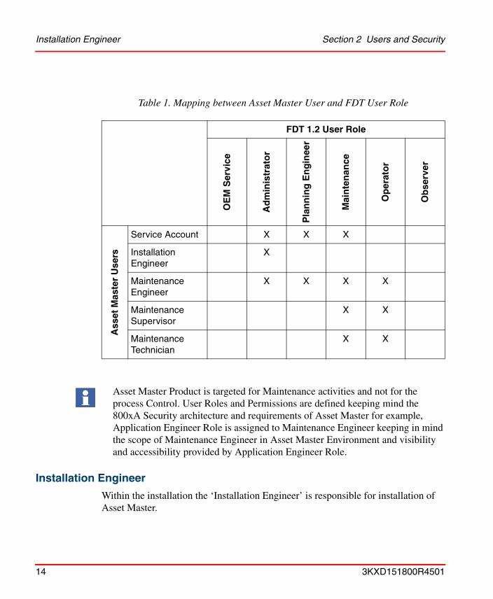
The users and user roles are created to match with the FDT user roles that are defined in the FDT specifications. Below table shows the Asset Master users and their mapping to the FDT user roles.
3KXD151800R4501 13
Installation Engineer Section 2 Users and Security
Installation Engineer
Within the installation the ‘Installation Engineer’ is responsible for installation of Asset Master.
Table 1. Mapping between Asset Master User and FDT User Role
FDT 1.2 User Role
OE
M S
ervi
ce
Ad
min
istr
ato
r
Pla
nn
ing
En
gin
eer
Mai
nte
nan
ce
Op
erat
or
Ob
serv
er
Ass
et M
aste
r U
sers
Service Account X X X
Installation Engineer
X
Maintenance Engineer
X X X X
Maintenance Supervisor
X X
Maintenance Technician
X X
Asset Master Product is targeted for Maintenance activities and not for the process Control. User Roles and Permissions are defined keeping mind the 800xA Security architecture and requirements of Asset Master for example, Application Engineer Role is assigned to Maintenance Engineer keeping in mind the scope of Maintenance Engineer in Asset Master Environment and visibility and accessibility provided by Application Engineer Role.
14 3KXD151800R4501

Section 2 Users and Security Asset Master Service Account
• Installation and import of single device object types via Device Library Wizard into the Asset Master. This covers also the installation of the DTM, Asset Monitor, etc.
The installation engineer needs knowledge of restrictions and limitations, as well as, dependencies of System Software Components and DTMs. Furthermore Installation Engineer must have additional Windows knowledge, due to the fact, that DCOM settings and Windows settings need to be done as pre-requisites for using device object types and DTMs.
Asset Master Service Account
The ‘Service Account’ is responsible for overall system administration including Asset Master services management.
Maintenance Engineer
‘Maintenance Engineer’ is responsible for configurations such as:
• Creating the field topology
• Instantiate the appropriate objects
• Prepare appropriate device function by setting parameters (offline/online)
• Posses all the permissions given to Supervisors and Technicians.
• Device management configuration using DTMs for device configuration, fieldbus builder for fieldbus network definitions, and asset optimization for defining asset monitors.
Maintenance Engineer must possess knowledge in Fieldbus technology, as well as process & device know-how.
During maintenance the Maintenance Engineer are responsible for:
• Supervising correct functioning of devices
• Reacting in case of faults
• Scheduling of appropriate action in case of observed performance degradation
This account is not used for any operation except to run the Asset Master product services i.e. service with This user settings run under this account.
3KXD151800R4501 15

Maintenance Supervisor & Maintenance Technician Section 2 Users and Security
Maintenance Engineer must possess device and process knowledge in order to decide accordingly on reported unexpected behaviours.
During commissioning the Maintenance Engineer is responsible for
• Downloading the pre-configured parameter sets to the devices
• Uploading pre-configured parameter sets from the devices in case of pre-configured devices
• Testing correct functioning of the device in itself
• Testing correct functioning of device within the automation application
Maintenance Engineer must posses basic knowledge of handling devices and its’ parameter sets, as well as, posses process and application know-how. Fieldbus know-how is needed in case the same person is responsible for, say, troubleshooting for Fieldbus problems.
During operation the Maintenance Engineer is responsible for:
• Making DTM parameter tuning changes and calibrating field devices.
Maintenance Supervisor & Maintenance Technician
During operation the Maintenance Technician is responsible for:
• Making DTM parameter tuning changes and calibrating field devices.
During operation the Maintenance Supervisor is responsible for:
• Monitoring asset monitors, initiating corrective actions, setting up calibration schedules, and approving calibration results.
• Approving and supervising Technicians’ actions. For example, provide digital signature for technicians’ actions.
During maintenance the Maintenance Supervisor is responsible for:
• Supervising correct functioning of devices
• Reacting in case of faults
• Scheduling of appropriate action in case of observed performance degradation
16 3KXD151800R4501

Section 2 Users and Security Configuration
ConfigurationAsset Master is powered by 800xA suit of software products and simply follows its security definition architecture. The 800xA Security model is based on extensions to Windows security model.
The extensions make it possible to set permissions for users or user groups on an 800xA System, a structure or part of a structure, or an Aspect Object.
Related to the security in the usage settings are roles. Roles adapt the user interface for different types of users, i.e. user groups. Some operations require a Maintenance Engineer or Maintenance Technician role.
However, having the correct role does not give the user the permission to perform the operation. The permission is completely controlled by the security configuration of the system.
Configuration of user roles mainly involves following steps:
1. Creation of windows users & user groups
2. Creation of user groups with in the Asset Master Workplace
3. Assigning appropriate user roles to each user group
4. Assigning required permissions to user group
5. Defining User Role Binding
6. Synchronizing both workplace and windows users groups and users
Creating Windows User Groups and Users
The following windows user groups are created on Asset Master Node:
1. IndustrialITUser - Created by System Installer
2. IndustrialITAdmin - Created by System Installer
3. Maintenance Technician – Created by System Installer
4. Maintenance Supervisor – Created by System Installer
5. Maintenance Engineer – Created by System Installer
6. Administrator – Default Windows Group
3KXD151800R4501 17

Creating Windows User Groups and Users Section 2 Users and Security
7. Power User – Default Windows Group
The Following Windows Users are created on Asset Master Node.
There is a one to one association between windows user groups and PPA user groups. For example, Asset Master Maintenance Engineers Group is associated with Windows Maintenance Engineers Group. Following user groups are created during restore of Asset Master Backup data (Asset Master is delivered as pre-configured software in the form of backup).
1. Everyone
2. Administrators
3. Application Engineers (Not Used in Asset Master)
4. Software Developers (Not Used in Asset Master)
5. System Engineers
6. Operators (Not Used in Asset Master)
7. Maintenance Technicians
8. Maintenance Supervisors
9. Maintenance Engineers
The Windows Users and User Groups (1 to 5) are created by the System Installer during the windows configuration phase.
Table 2. Mapping of Asset Master Users to Workplace & Windows User Groups.
User Full Name
AMInstall Asset Master Install User
AMServUser Asset Master Service Account
mnteng Maintenance Engineer
mntsupv maintenance Supervisor
mnttech Maintenance Technician
18 3KXD151800R4501

Section 2 Users and Security User Roles
Each Asset Master user is member of certain Asset Master user groups and windows user groups as shown in the table below:
User Roles
User roles help to customize the environment to suit the needs of each user.
This means that the operations which the user needs to take act on are visible for the user. The user role is used to adapt the user interface to work with Asset Master user groups. For example configuration dialogs are removed from users with an Operator Role.
The user roles are associated with the Asset Master user groups. By adding a Windows user to an Asset Master group a user is assigned a role.
The following User Roles exist in Asset Master:
Table 3. Mapping of Asset Master Users to Workplace & Windows User Groups.
UserMember of PPA User
Group(s)
Member of Windows User
Group(s)
Maintenance Engineer 1. Maintenance engineers
2. Maintenance Technicians
3. Everyone
1. Administrators
2. Power Users
Maintenance Supervisor 1. Maintenance Supervisors
2. Everyone
1. Users
Maintenance Technician 1. Maintenance Technicians
2. Everyone
1. Users
Service User 1. Administrators
2. Everyone
1. Administrators
2. Power Users
Install User 1. Administrators
2. System Engineers
3. Everyone
1. Administrators
2. Power Users
3KXD151800R4501 19
User Roles Section 2 Users and Security
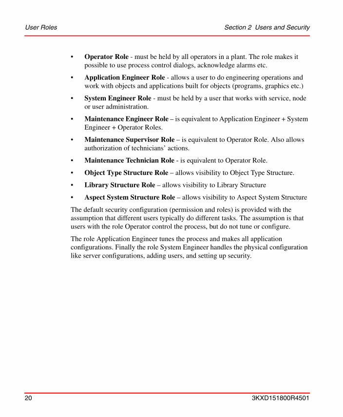
• Operator Role - must be held by all operators in a plant. The role makes it possible to use process control dialogs, acknowledge alarms etc.
• Application Engineer Role - allows a user to do engineering operations and work with objects and applications built for objects (programs, graphics etc.)
• System Engineer Role - must be held by a user that works with service, node or user administration.
• Maintenance Engineer Role – is equivalent to Application Engineer + System Engineer + Operator Roles.
• Maintenance Supervisor Role – is equivalent to Operator Role. Also allows authorization of technicians’ actions.
• Maintenance Technician Role - is equivalent to Operator Role.
• Object Type Structure Role – allows visibility to Object Type Structure.
• Library Structure Role – allows visibility to Library Structure
• Aspect System Structure Role – allows visibility to Aspect System Structure
The default security configuration (permission and roles) is provided with the assumption that different users typically do different tasks. The assumption is that users with the role Operator control the process, but do not tune or configure.
The role Application Engineer tunes the process and makes all application configurations. Finally the role System Engineer handles the physical configuration like server configurations, adding users, and setting up security.
20 3KXD151800R4501
Section 2 Users and Security User Permissions
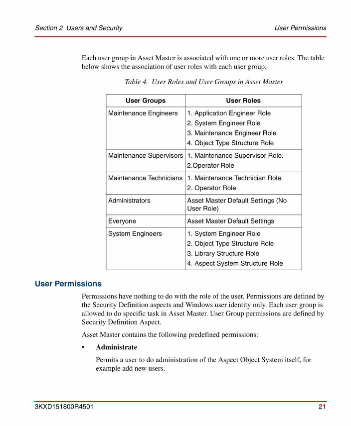
Each user group in Asset Master is associated with one or more user roles. The table below shows the association of user roles with each user group.
User Permissions
Permissions have nothing to do with the role of the user. Permissions are defined by the Security Definition aspects and Windows user identity only. Each user group is allowed to do specific task in Asset Master. User Group permissions are defined by Security Definition Aspect.
Asset Master contains the following predefined permissions:
• Administrate
Permits a user to do administration of the Aspect Object System itself, for example add new users.
Table 4. User Roles and User Groups in Asset Master
User Groups User Roles
Maintenance Engineers 1. Application Engineer Role
2. System Engineer Role
3. Maintenance Engineer Role
4. Object Type Structure Role
Maintenance Supervisors 1. Maintenance Supervisor Role.
2.Operator Role
Maintenance Technicians 1. Maintenance Technician Role.
2. Operator Role
Administrators Asset Master Default Settings (No User Role)
Everyone Asset Master Default Settings
System Engineers 1. System Engineer Role
2. Object Type Structure Role
3. Library Structure Role
4. Aspect System Structure Role
3KXD151800R4501 21
User Permissions Section 2 Users and Security
• Approve
Allows approval of a double authentication.
• Batch Configure
Permits a user to configure a batch operation.
• Break Reservation
Allows a user to break a reservation or check-out.
• Configure
Permits a user to configure an aspect.
• Download
Allows download to a controller or other equipment.
• Enter Environment
Permits a user to enter an environment.
• First Signature
Permission to make the first digital signature for an aspect.
• Modify Alarm Hiding
Permission to modify alarm hiding configuration.
• Modify History
Allows modification of version history.
• Operate
This is the default permission for OPC write operation. Permits a user to operate Asset Master. Normally given to the Operator Group.
• Operator Configure
Allows an operator to do some configuration work.
• Read
This is the default permission for read operation. Permits a user to read information.
22 3KXD151800R4501

Section 2 Users and Security User Permissions
• Second Signature
Permission to make the second digital signature for an aspect.
• Security Configure
Permits a user to change/add permission on Aspect Objects.
• Shutdown
Permits a user to shutdown an area. Not used in the default setting.
• Supervise
Permits a user to supervise the process.
• Tune
Permits a user to tune a process
Asset Master extends the default permission settings in 800xA as shown in table below:
There may be additional permissions depending on installed system extensions.
Table 5. Permission Settings in Asset Master
Group Permission
Maintenance Engineers Operate, Operator Configure Shutdown, Security Configure, Administrate, Supervise Configure, Tune, Download, Approve, Modify History, First Signature, Second Signature, Operator Configure, Break Reservation.
Maintenance Supervisors Operate, Operator Configure, First Signature, Second Signature, Approve
Maintenance Technicians Operate, Operator Configure
3KXD151800R4501 23

User Role Bindings and Structure Visibility Section 2 Users and Security
User Role Bindings and Structure Visibility
User Role Bindings configuration on aspect category level defines the available aspects and structures to the login user.
Table 6. User Role Bindings – Structure Visibility
Structures Install UserMaintenance
EngineerMaintenance Supervisor
Maintenance Technician
Admin X X
Aspect System X X
Asset X X X X
Control X X X X
Documentation X X X X
Functional X X X X
Graphics X
Library X X
Location X X X X
Maintenance X
Node Administration
X X
Object Type X X
Obsolete X
Product X
Product Type X X X X
Service X X
System X
Users X X X X
Workplace X
24 3KXD151800R4501

Section 3 Asset Optimization
Asset Optimization consists of system extensions to the 800xA Base System. Asset Optimization functionality includes Asset Condition Reporting, Asset Monitoring, CMMS (Computerized Maintenance Management System) Integration, and DMS Calibration Integration to the Asset Master. This optimizes the use of plant equipment and processes. When integrated with SMS and e-mail Messaging, Asset Optimization provides a method for sending messages based on alarm and event information to user devices such as mobile telephones, e-mail accounts, and pagers. When integrated with FOUNDATION Fieldbus Device Management, or PROFIBUS & HART Device Management, Asset Optimization provides a method for detecting field device problems.
For further information, refer to:• 3BUA000118R5001 - IndustrialIT 800xA Asset Optimization Configuration
• 3BUA000150R5001 - IndustrialIT 800xA Asset Optimization Operation
The documents can be found on DVD1 in the folder Released Documentation\800xA. Alternately, the latest version of the documents can be downloaded from ABB Solutions Bank.
3KXD151800R4501 25

Section 3 Asset Optimization
26 3KXD151800R4501
Section 4 Device Management & Fieldbuses
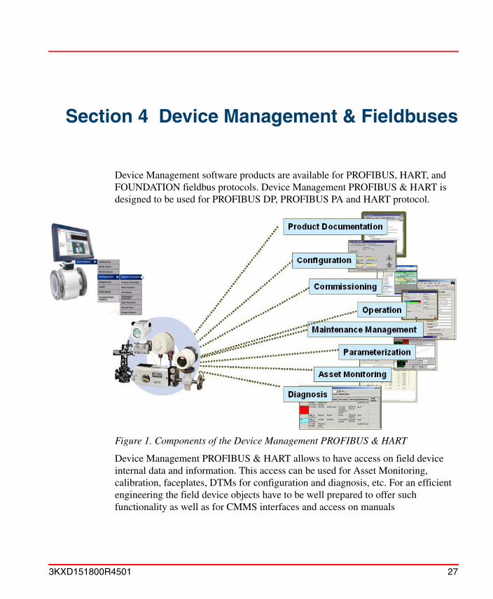
Device Management software products are available for PROFIBUS, HART, and FOUNDATION fieldbus protocols. Device Management PROFIBUS & HART is designed to be used for PROFIBUS DP, PROFIBUS PA and HART protocol.
Figure 1. Components of the Device Management PROFIBUS & HART
Device Management PROFIBUS & HART allows to have access on field device internal data and information. This access can be used for Asset Monitoring, calibration, faceplates, DTMs for configuration and diagnosis, etc. For an efficient engineering the field device objects have to be well prepared to offer such functionality as well as for CMMS interfaces and access on manuals
3KXD151800R4501 27

Section 4 Device Management & Fieldbuses
For further information, refer to:
• 3BDD011934R5001 - IndustrialIT 800xA Device Management PROFIBUS and HART Configuration
• 3BDD011938R5001 - IndustrialIT Fieldbus Basic PROFIBUS DTM Configuration
• 3BDD011939R5001 - IndustrialIT Fieldbus Basic HART DTM Configuration
• 3BDD011677R0501 - IndustrialIT 800xA Device Management FOUNDATION Fieldbus Configuration
• 3BDD011704R0201 - FieldIT PROFIBUS DP/PA Linking Device LD800P
• 3BDD012902R5001 - FieldIT FOUNDATION Fieldbus Linking Device LD 800HSE User Instructions
The documents can be found on DVD1 in the folder Released Documentation\800xA. Alternately, the latest version of the documents can be downloaded from ABB Solutions Bank.
28 3KXD151800R4501

Section 5 Access Management
For process critical operations, an aspect category may be configured to require an explicit authentication operation before the operation can be performed.
Two different authentication operations are supported:
• Re-authentication is used to guarantee that an operation is performed by the correct person. Requiring a re-authentication immediately before a change can be performed guarantees that no one can use a workplace if an operator temporarily leaves it.
• Double-authentication is used for operations critical to the quality of the product or required by regulation. It is used where the knowledge of an operator is limited or where it is required that another operator verifies the change before it is implemented.
For further information, refer to:• 3BSC037410R5001 - IndustrialIT 800xA System Administration and Security
• 3BDS011222R5001 - IndustrialIT 800xA System Configuration
The documents can be found on DVD1 in the folder Released Documentation\800xA. Alternately, the latest version of the documents can be downloaded from ABB Solutions Bank.
3KXD151800R4501 29

Section 5 Access Management
30 3KXD151800R4501

Section 6 OPC Data Access
Asset Master OPC functionality consists of two main functions, OPC Support and OPC Connect. This chapter deals with OPC Support. This function enables OPC Clients to connect to Asset Master in order for the client to read and write OPC data from/to Asset Master.
Asset Master OPC Support is typically used by an OPC Client in order to exchange data between Asset Master and third party software applications to be used.
Asset Master OPC Support exposes interfaces for OPC Data Access, OPC Alarm and Event, and OPC History Data Access. These are three central interface specifications as stated by the OPC Foundation. Refer to the 800xA Engineering Concepts manual for a definition and explanation of OPC.
In order to use OPC Support both hardware and software must be configured in certain ways.
The Asset Master license feature that the customer pays for to get Asset Master OPC Support is called ‘OPC Client Connection’.
To be considered when accessing the Asset Master OPC Servers:
Accessing the Asset Master OPC Servers will generate load in the system, which may affect normal operation. Especially adding items and doing reads and writes might affect other functions in the system.
For further information, refer to:
• 3BDS100972R5001 - IndustrialIT 800xA System Engineering Concepts
• 3BDS011222R5001 - IndustrialIT 800xA System Configuration
The documents can be found on DVD1 in the folder Released Documentation\800xA. Alternately, the latest version of the documents can be downloaded from ABB Solutions Bank.
3KXD151800R4501 31
Section 6 OPC Data Access
32 3KXD151800R4501

Section 7 PC, Network and SoftwareMonitoring
Standard PC and network equipment is used extensively in automation systems. The correct behavior and status of this equipment has a significant impact on the performance, reliability, and functional availability of an automation system and thus the industrial process being controlled.
The PC, Network and Software Monitoring (PNSM) software can independently monitor the status of Information Technology (IT) Assets. By default, IT Asset status is viewable via the Asset Master System Status Viewer, or through the standard faceplates provided with each of the predefined IT Assets. When used in conjunction with Asset Optimization Asset Monitoring, alarms can be generated based on error conditions, and IT Asset status is viewable via the Asset Viewer and Asset Reporter.
Once PNSM is installed in the Asset Master System, the data can be used to:
• Generate alarms.
• Produce historical reports.
• Update live trends and graphics.
Basic Computer Monitoring builds upon this framework to simplify the process of monitoring the workstation nodes in an Asset Master System. Workstation nodes are monitored for key health indicators and alarms are generated if monitored values deviate from expected limits.
3KXD151800R4501 33

Section 7 PC, Network and Software Monitoring
For further information, refer to:
• 3BUA000447R5001 - IndustrialIT 800xA Asset Optimization, PC, Network and Software Monitoring, Configuration
The documents can be found on DVD1 in the folder Released Documentation\800xA. Alternately, the latest version of the documents can be downloaded from ABB Solutions Bank.
34 3KXD151800R4501

Appendix A Terminology
This appendix lists the terms associated with Asset Master. We recommend you to memorize these terms.
Table 7. Terms Associated with Asset Master
Term Description
Aspect An aspect is the description of properties of an Aspect Object. Some examples of aspects are name, device management, DMS, and asset monitor.
Aspect category Specialization of an aspect type. For example, the Asset Monitors aspect type includes all of the Basic Asset Monitor aspect categories.
Aspect Object A computer representation of real objects such as pumps and valves or a number of virtual objects such as service or object type. An Aspect Object is described by its aspects and organised in structures.
Aspect Object Type Defines certain characteristics that are shared between several object instances, such as a basic set of common aspects. This makes it possible to create and efficiently re-use standardized solutions to frequently recurring problems. For example, rather than building an object from scratch for every valve in a plant, you can define a set of valve types, and then create all valve objects of these instances.
Aspect system A software system, which implements one or several aspect types by providing one or several aspect system objects.
3KXD151800R4201 35

Appendix A Terminology
Authentication The process by which the system validates the user's logon information. A user's name and password are compared against an authorized list. If the system detects a match, access is granted to the extent specified in the permissions list for that user.
Event A detectable occurrence, which is of significance to an Aspect Object. May or may not be associated with a condition. For example, the transitions into HighAlarm and Normal conditions are events, that are associated with conditions. However, operator actions, system configuration changes, and system errors are examples of events, that are not related to specific conditions. OPC Clients may subscribe to be notified of the occurrence of specified events.
IndustrialIT Industrial IT is ABB’s solution for business processes. It allows seamless integration of systems for plant automation, plant optimisation and common business processes at run time.
Node A computer communicating on a network e.g. the Internet, Plant, Control or I/O network. Each node typically has a unique node address with a format depending on the network it is connected to.
Table 7. Terms Associated with Asset Master
Term Description
36 3KXD151800R4201
Appendix A Terminology
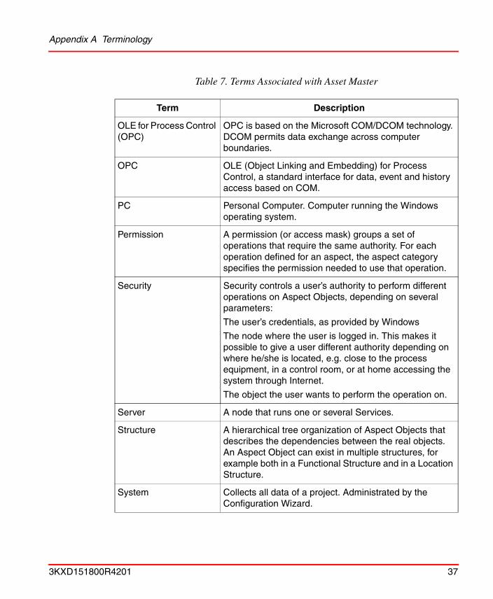
OLE for Process Control (OPC)
OPC is based on the Microsoft COM/DCOM technology. DCOM permits data exchange across computer boundaries.
OPC OLE (Object Linking and Embedding) for Process Control, a standard interface for data, event and history access based on COM.
PC Personal Computer. Computer running the Windows operating system.
Permission A permission (or access mask) groups a set of operations that require the same authority. For each operation defined for an aspect, the aspect category specifies the permission needed to use that operation.
Security Security controls a user’s authority to perform different operations on Aspect Objects, depending on several parameters:
The user’s credentials, as provided by Windows
The node where the user is logged in. This makes it possible to give a user different authority depending on where he/she is located, e.g. close to the process equipment, in a control room, or at home accessing the system through Internet.
The object the user wants to perform the operation on.
Server A node that runs one or several Services.
Structure A hierarchical tree organization of Aspect Objects that describes the dependencies between the real objects. An Aspect Object can exist in multiple structures, for example both in a Functional Structure and in a Location Structure.
System Collects all data of a project. Administrated by the Configuration Wizard.
Table 7. Terms Associated with Asset Master
Term Description
3KXD151800R4201 37

Appendix A Terminology
You should familiarise yourself with the following list of terms which refer to the FOUNDATION Fieldbus terminology.
The following is a list of terms associated with HART that you should be familiar with.
Table 8. FOUNDATION Fieldbus Terminology
Term Description
Fieldbus A Fieldbus is a digital, two-way, multi-drop communication link among intelligent measurement and control devices. It serves as a Local Area Network (LAN) for advanced process control, remote input/output and high speed factory automation applications.
Fieldbus device Device connected through an Asset Master supported fieldbus. Examples are smart sensors and actuators, but also controllers, robots, variable speed drives, etc., when these devices are connected through a supported fieldbus.
Table 9. HART Terminology
Term/Acronym Description
Device Type Manager (DTM)
Software component (device driver) for configuring, diagnosing, forcing, and displaying the measured variables, etc. of a field device. It is familiar with the way the device works and supplies device-specific documentation.
Fieldbus device Device connected through an Asset Master supported fieldbus. Examples are smart sensors and actuators, but also controllers, robots, variable speed drives, etc., when these devices are connected through a supported fieldbus.
38 3KXD151800R4201

Appendix A Terminology
The following is a list of terms associated with Asset Optimization that you should be familiar with.
Field Device Tool (FDT) The FDT concept describes the interface between a Frame Application and the device-specific software (DTM = Device Type Manager) of the device manufacturer. It enables devices produced by different manufacturers and different fieldbuses to be integrated in a single system. Currently supporting fieldbus protocols for PROFIBUS and HART.
Highway Addressable Remote Terminal (HART)
Digital communication protocol developed for applications in industrial process control.
Table 10. Asset Optimization Terminology
Term/Acronym Description
AO Asset Optimization.
Asset Master Workplace
Provides a user interface for maintenance personnel to support their daily workflow most efficiently.
Asset Monitor Application responsible for retrieving data from, and interacting with, multiple data servers, OLE for Process Control ® (OPC®) servers, etc.). It analyzes the data and when necessary, issues an Asset Condition Document and notifies the user of the detected condition.
DMS Device Management System (DMS) database software. Provides calibration and configuration management through the companion DHH810-MFT Series Calibrator/HART Communicator, and DHH800-MFC HART Communicator.
Table 9. HART Terminology
Term/Acronym Description
3KXD151800R4201 39

Appendix A Terminology
Fieldbus device Device connected through an Asset Master supported fieldbus. Examples are remote I/O and smart sensors and actuators, but also controllers, robots, variable speed drives, etc., when these devices are connected through a supported fieldbus.
SNMP Simple Network Management Protocol. A network management standard that defines a strategy for managing TCP/IP and Internet Packet Exchange (IPX) networks.
Table 10. Asset Optimization Terminology
Term/Acronym Description
40 3KXD151800R4201

ABB Inc.125 East County Line RoadWarminster, PA18974-4995USATel: +1 215 674 6000Fax: +1 215 674 7183
ABB LtdHoward Road, St. NeotsCambridgeshirePE 19 8EUUKTel: +44 (0)1480 475321Fax: +44 (0)1480 217948
ABB has Sales & Customer Sup-port expertise in over 100 coun-tries worldwide.
www.abb.com/instrumentation
The Company’s policy is one of continuous productimprovement and the right is reserved to modifythe information contained herein without notice.
Printed in USA (January 2007)
© ABB 2007
3KX
D15
1800
R45
01