
3IE4 Series - dpie.com€¦ · 2.5 CE AND FCC COMPATIBILITY ... SATADOM 3IE4 series 9 V1.0 TPS,...
24
3IE4 Series Customer: Customer Part Number: Innodisk Part Number: Innodisk Model Name: Date: Innodisk Approver Customer Approver
-
Upload
nguyenliem -
Category
Documents
-
view
213 -
download
0
Transcript of 3IE4 Series - dpie.com€¦ · 2.5 CE AND FCC COMPATIBILITY ... SATADOM 3IE4 series 9 V1.0 TPS,...

3IE4 Series
Customer:
Customer
Part Number:
Innodisk
Part Number:
Innodisk
Model Name:
Date:
Innodisk
Approver
Customer
Approver

SATADOM 3IE4 series
2 V1.0 TPS, Jan. 2017
Table of contents
1. PRODUCT OVERVIEW ......................................................................................................................................... 7
1.1 INTRODUCTION OF INNODISK SATADOM 3IE4 SERIES .................................................................. 7
1.2 PRODUCT VIEW AND MODELS ............................................................................................................... 7
1.3 SATA INTERFACE ................................................................................................................................... 7
2. PRODUCT SPECIFICATIONS ........................................................................................................................... 8
2.1 CAPACITY AND DEVICE PARAMETERS ................................................................................................... 8
2.2 PERFORMANCE ........................................................................................................................................ 8
2.3 ELECTRICAL SPECIFICATIONS ............................................................................................................... 9
2.3.1 Power Requirement ............................................................................................................................ 9
2.4 ENVIRONMENTAL SPECIFICATIONS ...................................................................................................... 9
2.4.1 Temperature Ranges ......................................................................................................................... 9
2.4.2 Humidity .................................................................................................................................................. 10
2.4.3 Shock and Vibration ......................................................................................................................... 10
2.4.4 Mean Time between Failures (MTBF) .................................................................................... 10
2.5 CE AND FCC COMPATIBILITY ............................................................................................................. 10
2.6 ROHS COMPLIANCE ............................................................................................................................. 10
2.7 RELIABILITY ......................................................................................................................................... 11
2.8 TRANSFER MODE .................................................................................................................................. 11
2.9 PIN ASSIGNMENT ................................................................................................................................. 12
2.10 MECHANICAL DIMENSIONS ............................................................................................................... 12
2.11 ASSEMBLY WEIGHT ........................................................................................................................... 14
2.12 SEEK TIME .......................................................................................................................................... 14
2.13 HOT PLUG ........................................................................................................................................... 14
2.14 NAND FLASH MEMORY ..................................................................................................................... 14
3. THEORY OF OPERATION ................................................................................................................................. 15
3.1 OVERVIEW ............................................................................................................................................. 15
3.2 SATA III CONTROLLER ...................................................................................................................... 15
3.3 ERROR DETECTION AND CORRECTION ................................................................................................ 15
3.4 WEAR-LEVELING .................................................................................................................................. 16
3.5 BAD BLOCKS MANAGEMENT ................................................................................................................ 16
3.6 IDATA GUARD ....................................................................................................................................... 16
3.7 GARBAGE COLLECTION ......................................................................................................................... 16
3.8 TRIM .................................................................................................................................................... 16
4. INSTALLATION REQUIREMENTS ............................................................................................................... 17
4.1 SATADOM 3IE4 PIN DIRECTIONS .................................................................................................. 17
4.2 ELECTRICAL CONNECTIONS FOR SATADOM 3IE4 .......................................................................... 17
4.3 DEVICE DRIVE ...................................................................................................................................... 17

SATADOM 3IE4 series
3 V1.0 TPS, Jan. 2017
4.4 POWER SUPPLY FOR SATDOM ........................................................................................................... 17
4.4.1 Power cable ........................................................................................................................................... 17
4.4.2 Pin8 and Pin7 VCC ............................................................................................................................. 18
4.5 WRITE PROTECTION ............................................................................................................................ 19
5. PART NUMBER RULE ......................................................................................................................................... 20
6. APPENDIX ............................................................................................................................................................... 21

SATADOM 3IE4 series
4 V1.0 TPS, Jan. 2017
REVISION HISTORY
Revision Description Date
V1.0 First Released Mar. 2017

SATADOM 3IE4 series
5 V1.0 TPS, Jan. 2017
List of Tables TABLE 1: DEVICE PARAMETERS..................................................................................................................................... 8
TABLE 2: SATADOM-SV/SL PERFORMANCE ......................................................................................................... 8
TABLE 3: SATADOM-MV PERFORMANCE ................................................................................................................ 8
TABLE 4: SATADOM-MH/ML PERFORMANCE ....................................................................................................... 9
TABLE 5: INNODISK SATADOM 3IE4 POWER REQUIREMENT ........................................................................... 9
TABLE 6: POWER CONSUMPTION ................................................................................................................................. 9
TABLE 7: TEMPERATURE RANGE FOR SATADOM 3IE4 ........................................................................................ 9
TABLE 8: SHOCK/VIBRATION TESTING FOR SATADOM 3IE4 ........................................................................ 10
TABLE 9: SATADOM 3IE4 MTBF ........................................................................................................................... 10
TABLE 10: SATADOM 3IE4 TBW .......................................................................................................................... 11
TABLE 11: INNODISK SATADOM 3IE4 PIN ASSIGNMENT ............................................................................... 12

SATADOM 3IE4 series
6 V1.0 TPS, Jan. 2017
List of Figures FIGURE 1: INNODISK SATADOM 3IE4 ................................................................................................................... 7
FIGURE 2: INNODISK SATADOM-SV 3IE4 MECHANICAL DIAGRAM .............................................................. 12
FIGURE 3: INNODISK SATADOM-SL 3IE4 MECHANICAL DIAGRAM ............................................................... 13
FIGURE 4: INNODISK SATADOM-MV 3IE4 MECHANICAL DIAGRAM ............................................................. 13
FIGURE 5: INNODISK SATADOM-ML 3IE4 MECHANICAL DIAGRAM .............................................................. 13
FIGURE 6: INNODISK SATADOM-MH 3IE4 MECHANICAL DIAGRAM ............................................................. 14
FIGURE 7: INNODISK SATADOM 3IE4 BLOCK DIAGRAM ................................................................................. 15
FIGURE 8: SIGNAL SEGMENT AND POWER SEGMENT ............................................................................................ 17
FIGURE 9: STANDARD POWER CABLE ........................................................................................................................ 17
FIGURE 10: PIN 8 / PIN 7 HOST DESIGN IN REFERENCE CIRCUIT.................................................................... 18
FIGURE 11: MV TYPE HARDWARE WRITE PROTECT POSITION ............................................................................ 19
FIGURE 12: ML/MH TYPE HARDWARE WRITE PROTECT POSITION .................................................................. 19

SATADOM 3IE4 series
7 V1.0 TPS, Jan. 2017
1. Product Overview
1.1 Introduction of Innodisk SATADOM 3IE4 series
Innodisk SATADOM 3IE4 is characterized by L3 architecture with the latest SATA III (6.0GHz)
Marvell NAND controller. Innodisk’s exclusive L3 architecture is L2 architecture multiplied LDPC
(Low Density Parity Check). L2 (Long Life) architecture is a 4K mapping algorithm that reduces
WAF and features a real-time wear leveling algorithm to provide high performance and prolong
lifespan with exceptional reliability. Innodisk SATADOM 3IE4 is designed for industrial field, and
supports several standard features, including TRIM, NCQ, and S.M.A.R.T. In addition, Innodisk’s
exclusive industrial-oriented firmware provides a flexible customization service, making it perfect
for a variety of industrial applications.
1.2 Product View and Models
Innodisk SATADOM 3IE4 is available in follow capacities within MLC flash ICs.
SATADOM-SV 3IE4 8GG-32GB
SATADOM-SL 3IE4 8GG-32GB
SATADOM-MV 3IE4 8GG-64GB
SATADOM-ML 3IE4 16GB-128GB
SATADOM-MH 3IE4 16GB-128GB
Figure 1: Innodisk SATADOM 3IE4
1.3 SATA Interface
Innodisk SATADOM 3IE4 supports SATA III interface, and compliant with SATA I and SATA II.

SATADOM 3IE4 series
8 V1.0 TPS, Jan. 2017
2. Product Specifications
2.1 Capacity and Device Parameters
SATADOM 3IE4 device parameters are shown in Table 1.
Table 1: Device parameters
Capacity Cylinders Heads Sectors LBA User
Capacity(MB)
8GB 15525 16 63 15649200 7641
16GB 16383 16 63 31277232 15272
32GB 16383 16 63 62533296 30533
64GB 16383 16 63 125045424 61057
128GB 16383 16 63 250069680 122104
2.2 Performance
Burst Transfer Rate: 6.0Gbps
Table 2: SATADOM-SV/SL Performance
Capacity 8GB 16GB 32GB
Sequential*
Read (max.) 250 MB/s 340 MB/s 340 MB/s
Sequential*
Write (max.) 80 MB/s 160 MB/s 230 MB/s
4KB Random**
Read (QD32) 12,000 IOPS 17,000 IOPS 22,000 IOPS
4KB Random**
Write (QD32) 12,000 IOPS 26,000 IOPS 29,000 IOPS
Table 3: SATADOM-MV Performance
Capacity 8GB 16GB 32GB 64GB
Sequential*
Read (max.) 250 MB/s 500 MB/s 530 MB/s 540 MB/s
Sequential*
Write (max.) 80 MB/s 160 MB/s 300 MB/s 400 MB/s
4KB Random**
Read (QD32) 12,000 IOPS 23,000 IOPS 30,000 IOPS 31,000 IOPS
4KB Random**
Write (QD32) 12,000 IOPS 27,000 IOPS 30,000 IOPS 31,000 IOPS

SATADOM 3IE4 series
9 V1.0 TPS, Jan. 2017
Table 4: SATADOM-MH/ML Performance
Capacity 16GB 32GB 64GB 128GB
Sequential*
Read (max.) 500 MB/s 530 MB/s 530 MB/s 540 MB/s
Sequential*
Write (max.) 170 MB/s 320 MB/s 360 MB/s 400 MB/s
4KB Random**
Read (QD32) 23,000 IOPS 30,000 IOPS 31,000 IOPS 31,000 IOPS
4KB Random**
Write (QD32) 27,000 IOPS 30,000 IOPS 32,000 IOPS 31,000 IOPS
Note: * Sequential performance is based on CrystalDiskMark 5.1.2 with file size 1000MB
** Random performance is based on IO meter with Queue Depth 32
2.3 Electrical Specifications
2.3.1 Power Requirement
Table 5: Innodisk SATADOM 3IE4 Power Requirement
Item Symbol Rating Unit
Input voltage VIN +5 DC +- 5% V
2.3.2 Power Consumption
Table 6: Power Consumption
Mode SV type SL type MV type ML/MH type
Read 89mA (max.) 93mA (max.) 180mA (max.) 100mA (max.)
Write 127mA (max.) 123mA (max.) 159mA (max.) 171mA (max.)
Idle 71mA (max.) 324mA (max.) 108mA (max.) 82mA (max.)
Pin 7/ Pin8 VCC
Initial* 1000mA(max.)
SV/SL Target: 32GB, MV Target: 64GB, ML/MH Target:128GB
*To design in Pin7/8 VCC on motherboard, 5V with 1A power supply is requested.
2.4 Environmental Specifications
2.4.1 Temperature Ranges
Table 7: Temperature range for SATADOM 3IE4
Temperature Range
Operating Standard Grade: 0°C to +70°C
Industrial Grade: -40°C to +85°C
Storage -55°C to +95°C

SATADOM 3IE4 series
10 V1.0 TPS, Jan. 2017
2.4.2 Humidity
Relative Humidity: 10-95%, non-condensing
2.4.3 Shock and Vibration
Table 8: Shock/Vibration Testing for SATADOM 3IE4
Reliability Test Conditions Reference Standards
Vibration 7 Hz to 2K Hz, 20G, 3 axes IEC 68-2-6
Mechanical Shock Duration: 0.5ms, 1500 G, 3 axes IEC 68-2-27
2.4.4 Mean Time between Failures (MTBF)
Table 7 summarizes the MTBF prediction results for various SATADOM 3IE4 configurations. The
analysis was performed using a RAM Commander™ failure rate prediction.
‧ Failure Rate: The total number of failures within an item population, divided by the total
number of life units expended by that population, during a particular measurement interval
under stated condition.
‧ Mean Time between Failures (MTBF): A basic measure of reliability for repairable items:
The mean number of life units during which all parts of the item perform within their specified
limits, during a particular measurement interval under stated conditions.
Table 9: SATADOM 3IE4 MTBF
Product Condition MTBF (Hours)
Innodisk SATADOM 3IE4 Telcordia SR-332 GB, 25°C >3,000,000
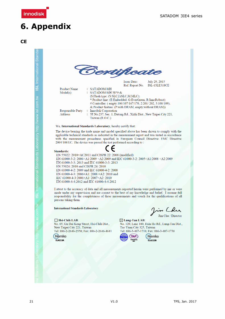
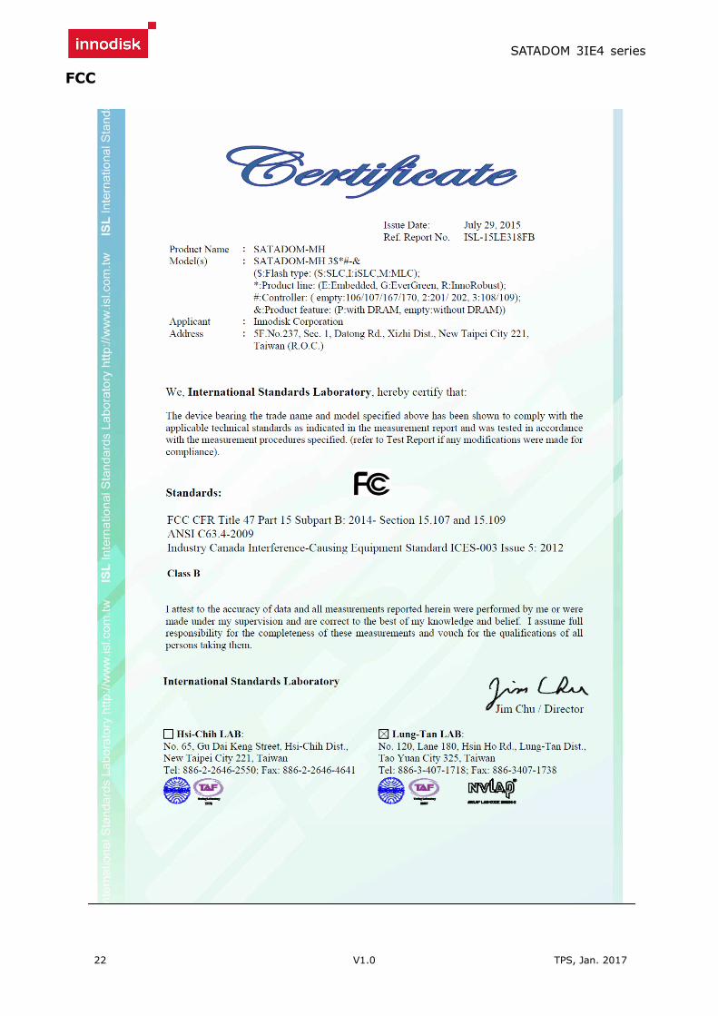
2.5 CE and FCC Compatibility
SATADOM 3IE4 conforms to CE and FCC requirements.
2.6 RoHS Compliance
SATADOM 3IE4 is fully compliant with RoHS directive.

SATADOM 3IE4 series
11 V1.0 TPS, Jan. 2017
2.7 Reliability
Table 10: SATADOM 3IE4 TBW
Parameter Value
Read Cycles Unlimited Read Cycles
Flash endurance 20,000 P/E cycles
Wear-Leveling Algorithm Support
Bad Blocks Management Support
Error Correct Code Support
TBW* (Total Bytes Written) Unit: TB
Capacity Sequential workload Client workload
08GB 156.3 104.2
16GB 312.5 208.3
32GB 625.0 416.7
64GB 1250.0 833.3
128GB 2500.0 1388.9
* Note:
1. Sequential: Mainly sequential write, tested by Vdbench.
2. Client: Follow JESD218 Test method and JESD219A Workload, tested by
ULINK. (The capacity lower than 64GB client workload is not specified in
JEDEC219A, the values are estimated.)
3. Based on out-of-box performance.
2.8 Transfer Mode
SATADOM 3IE4 support following transfer mode:
Serial ATA I 1.5Gbps
Serial ATA II 3.0Gbps
Serial ATA III 6.0Gbps

SATADOM 3IE4 series
12 V1.0 TPS, Jan. 2017
2.9 Pin Assignment
Innodisk SATADOM 3IE4 uses a standard SATA pin-out. See Table 8 for SATADOM 3IE4 pin
assignment.
Table 11: Innodisk SATADOM 3IE4 Pin Assignment
Name Type Description
Pin 0 GND Shielding
Pin 1 GND Shielding
Pin 2 A+ Differential signal to A
Pin 3 A- Differential signal to A-
Pin 4 GND Shielding
Pin 5 B- Differential signal to B-
Pin 6 B+ Differential signal to B
Pin 7 GND/ Vcc* Shielding/ +5V Power*
Pin 8 VCC +5V Power
* SATADOM 3IE4 default power supply through pin 8 or extra power cable.
Pin 7 power supply as an optional function with separated PN end of B.
2.10 Mechanical Dimensions
Figure 2: Innodisk SATADOM-SV 3IE4 mechanical diagram

SATADOM 3IE4 series
13 V1.0 TPS, Jan. 2017
Figure 3: Innodisk SATADOM-SL 3IE4 mechanical diagram
Figure 4: Innodisk SATADOM-MV 3IE4 mechanical diagram
Figure 5: Innodisk SATADOM-ML 3IE4 mechanical diagram

SATADOM 3IE4 series
14 V1.0 TPS, Jan. 2017
Figure 6: Innodisk SATADOM-MH 3IE4 mechanical diagram
2.11 Assembly Weight
An Innodisk SATADOM 3IE4 within flash ICs, 32GB’s weight is 7 grams approximately.
2.12 Seek Time
Innodisk SATADOM 3IE4 is not a magnetic rotating design. There is no seek or rotational latency
required.
2.13 Hot Plug
The SSD support hot plug function and can be removed or plugged-in during operation. User has
to avoid hot plugging the SSD which is configured as boot device and installed operation system.
Surprise hot plug : The insertion of a SATA device into a backplane (combine signal and power)
that has power present. The device powers up and initiates an OOB
sequence.
Surprise hot removal: The removal of a SATA device from a powered backplane, without first being
placed in a quiescent state.
2.14 NAND Flash Memory
Innodisk SATADOM 3IE4 uses Multi Level Cell (MLC) NAND flash memory, which is non-volatility,
high reliability and high speed memory storage. Each cell stores 2 bits or holds four states per cell.
Read or Write data to flash memory for SSD is control by microprocessor.

SATADOM 3IE4 series
15 V1.0 TPS, Jan. 2017
3. Theory of Operation
3.1 Overview
Figure 3 shows the operation of Innodisk SATADOM 3IE4 from the system level, including the
major hardware blocks.
Figure 7: Innodisk SATADOM 3IE4 Block Diagram
Innodisk SATADOM 3IE4 integrates a SATA III controller and NAND flash memories.
Communication with the host occurs through the host interface, using the standard ATA protocol.
Communication with the flash device(s) occurs through the flash interface.
3.2 SATA III Controller
Innodisk SATADOM 3IE4 is designed with 88NV1120, a SATA III 6.0Gbps (Gen. 3) controller. The
Serial ATA physical, link and transport layers are compliant with Serial ATA Gen 1, Gen 2 and Gen
3 specification (Gen 3 supports 1.5Gbps/3.0Gbps/6.0Gbps data rate). The controller has 2
channels for flash interface.
3.3 Error Detection and Correction
Innodisk SATADOM 3IE4 is designed with hardware LDPC ECC engine with hard-decision and
soft-decision decoding. Low-density parity-check (LDPC) codes have excellent error correcting
performance close to the Shannon limit when decoded with the belief-propagation (BP) algorithm
using soft-decision information.

SATADOM 3IE4 series
16 V1.0 TPS, Jan. 2017
3.4 Wear-Leveling
Flash memory can be erased within a limited number of times. This number is called the erase
cycle limit or write endurance limit and is defined by the flash array vendor. The erase cycle
limit applies to each individual erase block in the flash device.
Innodisk SATADOM-ML 3IE4 uses a static wear-leveling algorithm to ensure that consecutive
writes of a specific sector are not written physically to the same page/block in the flash. This
spreads flash media usage evenly across all pages, thereby extending flash lifetime.
3.5 Bad Blocks Management
Bad Blocks are blocks that contain one or more invalid bits whose reliability are not guaranteed.
The Bad Blocks may be presented while the SSD is shipped, or may develop during the life time of
the SSD. When the Bad Blocks is detected, it will be flagged, and not be used anymore. The SSD
implement Bad Blocks management, Bad Blocks replacement, Error Correct Code to avoid data
error occurred. The functions will be enabled automatically to transfer data from Bad Blocks to
spare blocks, and correct error bit.
3.6 iData Guard
Innodisk’s power cycling management is a comprehensive data protection mechanism that
functions before and after a sudden power outage to SSD. Low-power detection terminates data
writing before an abnormal power-off, while table-remapping after power-on deletes corrupt data
and maintains data integrity. Innodisk’s power cycling provides effective power cycling
management, preventing data stored in flash from degrading with use.
3.7 Garbage Collection
Garbage collection is used to maintain data consistency and perform continual data cleansing on
SSDs. It runs as a background process, freeing up valuable controller resources while sorting good
data into available blocks, and deleting bad blocks. It also significantly reduces write operations to
the drive, thereby increasing the SSD’s speed and lifespan.
3.8 TRIM
The TRIM command is designed to enable the operating system to notify the SSD which pages no
longer contain valid data due to erases either by the user or operating system itself. During a
delete operation, the OS will mark the sectors as free for new data and send a TRIM command to
the SSD to mark them as not containing valid data. After that the SSD knows not to preserve the
contents of the block when writing a page, resulting in less write amplification with fewer writes to
the flash, higher write speed, and increased drive life.

SATADOM 3IE4 series
17 V1.0 TPS, Jan. 2017
4. Installation Requirements
4.1 SATADOM 3IE4 Pin Directions
Figure 8: Signal Segment and Power Segment
* SATADOM 3IE4 default power supply through pin 8 or extra power cable.
Pin 7 power supply as an optional function with separate PN end of B.
4.2 Electrical Connections for SATADOM 3IE4
A Serial ATA device may be either directly connected to a host or connected to a host through a
cable. For connection via cable, the cable should be no longer than 1 meter. The SATA interface
has a separate connector for the power supply. Please refer to the pin description for further
details.
4.3 Device Drive
No additional device drives are required. The Innodisk SATADOM 3IE4 can be configured as a boot
device.
4.4 Power supply for SATDOM
4.4.1 Power cable
A power cable is shipped with each SATADOM product, which has standard 4 pins power connector
and special 3 pins power connector for SATADOM. The male and female power connector of
SATADOM have foolproof design to avoid misconnection, please check it before power on.
Innodisk also can customize the power connector for different host power socket design.
Figure 9: Standard power cable
*

SATADOM 3IE4 series
18 V1.0 TPS, Jan. 2017
4.4.2 Pin8 and Pin7 VCC
Innodisk’s SATADOM SSDs provide an elegant, compact option for SSD storage in embedded
systems, industrial PCs and server motherboards with their small form factor that connects
directly to the SATA connector on the motherboard. This simplified SSD design not only frees up
a precious drive bay for other storage options but eliminates messy, obtrusive SATA data cabling.
Innodisk’s patented Pin7 and Pin 8 SATA Power technologies take the cable-less concept to the
next step by also eliminating the need for power cables for a 100% cable-less, shock resistant,
space saving plug-and-play storage solution that optimizes airflow and makes the best use of
limited board space in embedded and rackmount server systems.
SATADOM 3IE4 series with Pin8/Pin7 VCC, it is defined Pin8/Pin7 as VCC on the SATA connector.
Thus the power would come from SATA connector Pin8/Pin7 VCC. Customers DO NOT have to use
the power cable for power supply. Such a cable-less design of SATADOM 3IE4 series with
Pin8/Pin7 VCC brings more convenience to customers’ system. The followings are the points
customers have to be careful of while designing in SATADOM 3IE4 series with Pin8/Pin7 VCC.
When customers use SATADOM with Pin8/Pin7 VCC and the host SATA socket does not have power
on Pin8/Pin7, external power must be provided to the SATADOM from the 3pin connector on the
side.To have the advantages of SATADOM 3IE4 series with Pin8/Pin7 VCC, and to avoid any
potential damage on customer’s board designed with VCC power supply. Innodisk suggests that
customers MUST design their board with a fuse which should be designed before the SATA socket
Pin8/Pin7 VCC. In other words, customers are suggested NOT TO layout 5V VCC to SATA socket on
board directly. A circuit diagram example to explain this is shown as below.
Figure 10: Pin 8 / Pin 7 host design in reference circuit
SATADOM 3IE4 series
19 V1.0 TPS, Jan. 2017
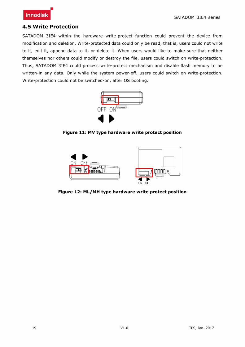
4.5 Write Protection
SATADOM 3IE4 within the hardware write-protect function could prevent the device from
modification and deletion. Write-protected data could only be read, that is, users could not write
to it, edit it, append data to it, or delete it. When users would like to make sure that neither
themselves nor others could modify or destroy the file, users could switch on write-protection.
Thus, SATADOM 3IE4 could process write-protect mechanism and disable flash memory to be
written-in any data. Only while the system power-off, users could switch on write-protection.
Write-protection could not be switched-on, after OS booting.
Figure 11: MV type hardware write protect position
Figure 12: ML/MH type hardware write protect position

SATADOM 3IE4 series
20 V1.0 TPS, Jan. 2017
5. Part Number Rule
CODE
1 2 3 4 5 6 7 8 9 10 11 12 13 14 15 16 17 18 19 20 21
D H S M H - 3 2 G M 4 1 B C A D C A X X X
Definition
Code 1st (Disk) Code 14th (Operation Temperature)
D: Disk C: Standard Grade (0℃~ +70℃)
Code 2nd (Feature set) W: Industrial Grade (-40℃~ +85℃)
H: iSLC series
Code 3rd ~5th (Form factor) Code 15th (Internal control)
SSV: SATADOM-SV SSL: SATADOM-SL 1~0: TSOP PCB version
SMV: SATADOM-MV SML: SATADOM-ML A~Z: BGA PCB version
SMH: SATADOM
Code 16th (Channel of data transfer)
Code 7th ~9th (Capacity) D: Dual Channel
08G:8GB 16G:16GB 32G:32GB 64G:64GB
A28:128GB
Code 10th ~12th (Controller) Code 17th (Flash Type)
M41: Artemis C: Toshiba MLC
Code 18th (Power supply config.)
Code 13th (Flash mode) A: Pin8 version / Standard version
B: Synchronous flash for Toshiba 15nm B: Pin8 & Pin7 version
Code 19th~21st (Customize code)
SATADOM 3IE4 series
21 V1.0 TPS, Jan. 2017
6. Appendix
CE
SATADOM 3IE4 series
22 V1.0 TPS, Jan. 2017
FCC

SATADOM 3IE4 series
23 V1.0 TPS, Jan. 2017
REACH

SATADOM 3IE4 series
24 V1.0 TPS, Jan. 2017
RoHS