3HAC021313-001 RevK en - Lewis Australiamail.lewis.com.au/public/ABB/Shortened Product Manual - IRC...
39
Product manual Robot controller IRC5
Transcript of 3HAC021313-001 RevK en - Lewis Australiamail.lewis.com.au/public/ABB/Shortened Product Manual - IRC...

Product manual
Robot controller
IRC5


© C
opyr
ight
200
4-20
08 A
BB
. All
righ
ts r
eser
ved.
Product manual
Robot Controller
IRC5
M2004
Document ID: 3HAC021313-001
Revision: K
© C
opyr
ight
200
4-20
08 A
BB
. All
righ
ts r
eser
ved.
The information in this manual is subject to change without notice and should not be construed as a commitment by ABB. ABB assumes no responsibility for any errors that may appear in this manual.
Except as may be expressly stated anywhere in this manual, nothing herein shall be construed as any kind of guarantee or warranty by ABB for losses, damages to persons or property, fitness for a specific purpose or the like.
In no event shall ABB be liable for incidental or consequential damages arising from use of this manual and products described herein.
This manual and parts thereof must not be reproduced or copied without ABB's written permission, and contents thereof must not be imparted to a third party nor be used for any unauthorized purpose. Contravention will be prosecuted.
Additional copies of this manual may be obtained from ABB at its then current charge.
© Copyright 2004-2008 ABB All rights reserved.
ABB ABRobotics Products
SE-721 68 Västerås Sweden

Table of Contents
33HAC021313-001 Revision: K
© C
opyr
ight
200
4-20
08 A
BB
. All
righ
ts r
eser
ved.
Overview . . . . . . . . . . . . . . . . . . . . . . . . . . . . . . . . . . . . . . . . . . . . . . . . . . . . . . . . . . . . . . . . . . . . . . . . . . . . . 7Product documentation, M2004 . . . . . . . . . . . . . . . . . . . . . . . . . . . . . . . . . . . . . . . . . . . . . . . . . . . . . . . . . . . 11
1 Safety 13
1.1 Introduction . . . . . . . . . . . . . . . . . . . . . . . . . . . . . . . . . . . . . . . . . . . . . . . . . . . . . . . . . . . . . . . . . . . . . . . 13
1.2 General safety information. . . . . . . . . . . . . . . . . . . . . . . . . . . . . . . . . . . . . . . . . . . . . . . . . . . . . . . . . . . 141.2.1 Introduction . . . . . . . . . . . . . . . . . . . . . . . . . . . . . . . . . . . . . . . . . . . . . . . . . . . . . . . . . . . . . . . . . . 141.2.2 General Information . . . . . . . . . . . . . . . . . . . . . . . . . . . . . . . . . . . . . . . . . . . . . . . . . . . . . . . . . . . 15
1.2.2.1 Safety in the robot system . . . . . . . . . . . . . . . . . . . . . . . . . . . . . . . . . . . . . . . . . . . . . . . . . 151.2.3 Safety risks . . . . . . . . . . . . . . . . . . . . . . . . . . . . . . . . . . . . . . . . . . . . . . . . . . . . . . . . . . . . . . . . . . 16
1.2.3.1 Risks associated with live electric parts . . . . . . . . . . . . . . . . . . . . . . . . . . . . . . . . . . . . . . 161.2.4 Safety actions . . . . . . . . . . . . . . . . . . . . . . . . . . . . . . . . . . . . . . . . . . . . . . . . . . . . . . . . . . . . . . . . 17
1.2.4.1 Fire extinguishing . . . . . . . . . . . . . . . . . . . . . . . . . . . . . . . . . . . . . . . . . . . . . . . . . . . . . . . 171.2.5 Safety stops. . . . . . . . . . . . . . . . . . . . . . . . . . . . . . . . . . . . . . . . . . . . . . . . . . . . . . . . . . . . . . . . . . 18
1.2.5.1 Overview of robot stopping functions. . . . . . . . . . . . . . . . . . . . . . . . . . . . . . . . . . . . . . . . 181.2.5.2 What is an emergency stop? . . . . . . . . . . . . . . . . . . . . . . . . . . . . . . . . . . . . . . . . . . . . . . . 231.2.5.3 What is a safety stop? . . . . . . . . . . . . . . . . . . . . . . . . . . . . . . . . . . . . . . . . . . . . . . . . . . . . 241.2.5.4 What is safeguarding? . . . . . . . . . . . . . . . . . . . . . . . . . . . . . . . . . . . . . . . . . . . . . . . . . . . 25
1.3 Safety related instructions . . . . . . . . . . . . . . . . . . . . . . . . . . . . . . . . . . . . . . . . . . . . . . . . . . . . . . . . . . . 261.3.1 Safety signals, general . . . . . . . . . . . . . . . . . . . . . . . . . . . . . . . . . . . . . . . . . . . . . . . . . . . . . . . . . . 261.3.2 DANGER - Make sure that the main power has been switched off! . . . . . . . . . . . . . . . . . . . . . . . 281.3.3 WARNING - The unit is sensitive to ESD! . . . . . . . . . . . . . . . . . . . . . . . . . . . . . . . . . . . . . . . . . . 291.3.4 CAUTION - Never stand on or use the cabinet as a ladder . . . . . . . . . . . . . . . . . . . . . . . . . . . . . . 301.3.5 CAUTION - Make sure that there are no loose screws or turnings inside the computer unit
DSQC639 . . . . . . . . . . . . . . . . . . . . . . . . . . . . . . . . . . . . . . . . . . . . . . . . . . . . . . . . . . . . . . . . . . . . 311.3.6 CAUTION - Close the cabinet door . . . . . . . . . . . . . . . . . . . . . . . . . . . . . . . . . . . . . . . . . . . . . . . . 321.3.7 CAUTION - Hot components in controller . . . . . . . . . . . . . . . . . . . . . . . . . . . . . . . . . . . . . . . . . . 33
2 Installation and Commissioning, IRC5 35
2.1 Overview . . . . . . . . . . . . . . . . . . . . . . . . . . . . . . . . . . . . . . . . . . . . . . . . . . . . . . . . . . . . . . . . . . . . . . . . . 352.2 Installation Activities . . . . . . . . . . . . . . . . . . . . . . . . . . . . . . . . . . . . . . . . . . . . . . . . . . . . . . . . . . . . . . . . 36
2.3 Transporting and handling. . . . . . . . . . . . . . . . . . . . . . . . . . . . . . . . . . . . . . . . . . . . . . . . . . . . . . . . . . . 372.3.1 Lifting the controller modules . . . . . . . . . . . . . . . . . . . . . . . . . . . . . . . . . . . . . . . . . . . . . . . . . . . 372.3.2 Unpacking, IRC5 Controller . . . . . . . . . . . . . . . . . . . . . . . . . . . . . . . . . . . . . . . . . . . . . . . . . . . . . 38
2.4 On-site Installation . . . . . . . . . . . . . . . . . . . . . . . . . . . . . . . . . . . . . . . . . . . . . . . . . . . . . . . . . . . . . . . . . 402.4.1 Required installation space, IRC5 Controller. . . . . . . . . . . . . . . . . . . . . . . . . . . . . . . . . . . . . . . . . 402.4.2 Bolting down the controller . . . . . . . . . . . . . . . . . . . . . . . . . . . . . . . . . . . . . . . . . . . . . . . . . . . . . . 412.4.3 Transportation screws. . . . . . . . . . . . . . . . . . . . . . . . . . . . . . . . . . . . . . . . . . . . . . . . . . . . . . . . . . . 422.4.4 Mounting the FlexPendant holder . . . . . . . . . . . . . . . . . . . . . . . . . . . . . . . . . . . . . . . . . . . . . . . . . 43
2.5 Connections . . . . . . . . . . . . . . . . . . . . . . . . . . . . . . . . . . . . . . . . . . . . . . . . . . . . . . . . . . . . . . . . . . . . . . 472.5.1 Connectors on controller, IRC5 . . . . . . . . . . . . . . . . . . . . . . . . . . . . . . . . . . . . . . . . . . . . . . . . . . . 472.5.2 Connecting a FlexPendant . . . . . . . . . . . . . . . . . . . . . . . . . . . . . . . . . . . . . . . . . . . . . . . . . . . . . . . 512.5.3 Connecting a PC to the service port . . . . . . . . . . . . . . . . . . . . . . . . . . . . . . . . . . . . . . . . . . . . . . . . 522.5.4 Connection to serial channel connector . . . . . . . . . . . . . . . . . . . . . . . . . . . . . . . . . . . . . . . . . . . . . 552.5.5 Connecting power supply to the Single Cabinet Controller . . . . . . . . . . . . . . . . . . . . . . . . . . . . . . 582.5.6 Connecting power supply to the Dual Cabinet Controller . . . . . . . . . . . . . . . . . . . . . . . . . . . . . . . 612.5.7 Connecting the communication cabling for the Dual Cabinet Controller . . . . . . . . . . . . . . . . . . . 632.5.8 Fitting the connector. . . . . . . . . . . . . . . . . . . . . . . . . . . . . . . . . . . . . . . . . . . . . . . . . . . . . . . . . . . . 652.5.9 Connecting the manipulator to the IRC5 controller . . . . . . . . . . . . . . . . . . . . . . . . . . . . . . . . . . . . 672.5.10 The MOTORS ON/MOTORS OFF circuit . . . . . . . . . . . . . . . . . . . . . . . . . . . . . . . . . . . . . . . . . 682.5.11 Connection of external safety relay . . . . . . . . . . . . . . . . . . . . . . . . . . . . . . . . . . . . . . . . . . . . . . . 732.5.12 Connection to MOTORS ON/MOTORS OFF contactor . . . . . . . . . . . . . . . . . . . . . . . . . . . . . . . 742.5.13 Connection of Drive Module Disconnect, by limit switch. . . . . . . . . . . . . . . . . . . . . . . . . . . . . . 762.5.14 Connection of servo disconnect, by servo power switch . . . . . . . . . . . . . . . . . . . . . . . . . . . . . . . 80

Table of Contents
4 3HAC021313-001 Revision: K
© C
opyr
ight
200
4-20
08 A
BB
. All
righ
ts r
eser
ved.
2.5.15 Connecting a Limit switch override push button . . . . . . . . . . . . . . . . . . . . . . . . . . . . . . . . . . . . . 82
2.6 Drive system . . . . . . . . . . . . . . . . . . . . . . . . . . . . . . . . . . . . . . . . . . . . . . . . . . . . . . . . . . . . . . . . . . . . . . 872.6.1 Drive functions, general . . . . . . . . . . . . . . . . . . . . . . . . . . . . . . . . . . . . . . . . . . . . . . . . . . . . . . . . . 872.6.2 Configuration of the drive system, IRC5 . . . . . . . . . . . . . . . . . . . . . . . . . . . . . . . . . . . . . . . . . . . . 88
2.7 Memory functions. . . . . . . . . . . . . . . . . . . . . . . . . . . . . . . . . . . . . . . . . . . . . . . . . . . . . . . . . . . . . . . . . . 962.7.1 Memory functions, IRC5 . . . . . . . . . . . . . . . . . . . . . . . . . . . . . . . . . . . . . . . . . . . . . . . . . . . . . . . . 962.7.2 Connecting a USB memory to the computer unit . . . . . . . . . . . . . . . . . . . . . . . . . . . . . . . . . . . . . 97
2.8 I/O system . . . . . . . . . . . . . . . . . . . . . . . . . . . . . . . . . . . . . . . . . . . . . . . . . . . . . . . . . . . . . . . . . . . . . . . 1002.8.1 Definition of I/O units, IRC5 . . . . . . . . . . . . . . . . . . . . . . . . . . . . . . . . . . . . . . . . . . . . . . . . . . . . 100
2.9 Installation of add-ons . . . . . . . . . . . . . . . . . . . . . . . . . . . . . . . . . . . . . . . . . . . . . . . . . . . . . . . . . . . . . 1022.9.1 Installation of additional Drive Module. . . . . . . . . . . . . . . . . . . . . . . . . . . . . . . . . . . . . . . . . . . . 1022.9.2 Installation of external operator's panel, IRC5. . . . . . . . . . . . . . . . . . . . . . . . . . . . . . . . . . . . . . . 1062.9.3 Installation of Drive system parts . . . . . . . . . . . . . . . . . . . . . . . . . . . . . . . . . . . . . . . . . . . . . . . . 1112.9.4 Installation of I/O, Gateways and encoder interface units, IRC5 . . . . . . . . . . . . . . . . . . . . . . . . 1132.9.5 Installation of PMC-card for Force Control Function . . . . . . . . . . . . . . . . . . . . . . . . . . . . . . . . . 1152.9.6 Installation of extra mass memory in computer unit DSQC623 . . . . . . . . . . . . . . . . . . . . . . . . . 1192.9.7 Installation of Euromap and SPI . . . . . . . . . . . . . . . . . . . . . . . . . . . . . . . . . . . . . . . . . . . . . . . . . 1232.9.8 Upgrading and installation of 2X Euromap interface (Option 671-4) . . . . . . . . . . . . . . . . . . . . . 1312.9.9 Installation of cooling fan harness axis 1 and 2 . . . . . . . . . . . . . . . . . . . . . . . . . . . . . . . . . . . . . . 1392.9.10 Installation of Hot plug . . . . . . . . . . . . . . . . . . . . . . . . . . . . . . . . . . . . . . . . . . . . . . . . . . . . . . . 1442.9.11 Installing the EPS board DSQC 646 for Electronic Position Switches . . . . . . . . . . . . . . . . . . . 1522.9.12 Installing the SafeMove board DSQC 647. . . . . . . . . . . . . . . . . . . . . . . . . . . . . . . . . . . . . . . . . 1582.9.13 Installation of Remote Service . . . . . . . . . . . . . . . . . . . . . . . . . . . . . . . . . . . . . . . . . . . . . . . . . . 166
3 Maintenance activities, controller IRC5 169
3.1 Maintenance schedule, controller IRC5 . . . . . . . . . . . . . . . . . . . . . . . . . . . . . . . . . . . . . . . . . . . . . . . . 169
3.2 Inspection activities . . . . . . . . . . . . . . . . . . . . . . . . . . . . . . . . . . . . . . . . . . . . . . . . . . . . . . . . . . . . . . . 1703.2.1 Inspection of the controller . . . . . . . . . . . . . . . . . . . . . . . . . . . . . . . . . . . . . . . . . . . . . . . . . . . . . 170
3.3 Changing/replacing activities . . . . . . . . . . . . . . . . . . . . . . . . . . . . . . . . . . . . . . . . . . . . . . . . . . . . . . . 1723.3.1 Activities . . . . . . . . . . . . . . . . . . . . . . . . . . . . . . . . . . . . . . . . . . . . . . . . . . . . . . . . . . . . . . . . . . . 1723.3.2 Replacement of moist dust filter . . . . . . . . . . . . . . . . . . . . . . . . . . . . . . . . . . . . . . . . . . . . . . . . . 173
3.4 Cleaning activities . . . . . . . . . . . . . . . . . . . . . . . . . . . . . . . . . . . . . . . . . . . . . . . . . . . . . . . . . . . . . . . . 1763.4.1 Cleaning of the IRC5 controller . . . . . . . . . . . . . . . . . . . . . . . . . . . . . . . . . . . . . . . . . . . . . . . . . . 1763.4.2 Cleaning moist dust filter . . . . . . . . . . . . . . . . . . . . . . . . . . . . . . . . . . . . . . . . . . . . . . . . . . . . . . . 1773.4.3 Cleaning the FlexPendant . . . . . . . . . . . . . . . . . . . . . . . . . . . . . . . . . . . . . . . . . . . . . . . . . . . . . . 179
4 Repair activities, controller IRC5 183
4.1 Overview . . . . . . . . . . . . . . . . . . . . . . . . . . . . . . . . . . . . . . . . . . . . . . . . . . . . . . . . . . . . . . . . . . . . . . . . 1834.2 Replacement of panel board . . . . . . . . . . . . . . . . . . . . . . . . . . . . . . . . . . . . . . . . . . . . . . . . . . . . . . . . . . 184
4.3 Replacement of power supply . . . . . . . . . . . . . . . . . . . . . . . . . . . . . . . . . . . . . . . . . . . . . . . . . . . . . . . 1874.3.1 Replacement of control power supply . . . . . . . . . . . . . . . . . . . . . . . . . . . . . . . . . . . . . . . . . . . . . 1874.3.2 Replacement of power distribution board . . . . . . . . . . . . . . . . . . . . . . . . . . . . . . . . . . . . . . . . . . 1904.3.3 Replacement of customer I/O power supply, IRC5 . . . . . . . . . . . . . . . . . . . . . . . . . . . . . . . . . . . 1934.3.4 Replacement of customer I/O power supply . . . . . . . . . . . . . . . . . . . . . . . . . . . . . . . . . . . . . . . . 1964.3.5 Replacement of drive system power supply. . . . . . . . . . . . . . . . . . . . . . . . . . . . . . . . . . . . . . . . . 1994.3.6 Replacement of system power supply . . . . . . . . . . . . . . . . . . . . . . . . . . . . . . . . . . . . . . . . . . . . . 202
4.4 Replacement of Flange disconnect. . . . . . . . . . . . . . . . . . . . . . . . . . . . . . . . . . . . . . . . . . . . . . . . . . . . . 2054.5 Replacement of I/O units and Gateways . . . . . . . . . . . . . . . . . . . . . . . . . . . . . . . . . . . . . . . . . . . . . . . . 2084.6 Replacement of backup energy bank . . . . . . . . . . . . . . . . . . . . . . . . . . . . . . . . . . . . . . . . . . . . . . . . . . . 2114.7 Replacement of control system fan . . . . . . . . . . . . . . . . . . . . . . . . . . . . . . . . . . . . . . . . . . . . . . . . . . . . 2144.8 Replacement of heat exchange unit and fan. . . . . . . . . . . . . . . . . . . . . . . . . . . . . . . . . . . . . . . . . . . . . . 2184.9 Replacement of computer unit DSQC623 . . . . . . . . . . . . . . . . . . . . . . . . . . . . . . . . . . . . . . . . . . . . . . . 2224.10 Replacement of computer unit DSQC639 . . . . . . . . . . . . . . . . . . . . . . . . . . . . . . . . . . . . . . . . . . . . . . 226
Table of Contents
53HAC021313-001 Revision: K
© C
opyr
ight
200
4-20
08 A
BB
. All
righ
ts r
eser
ved.
4.11 Replacement of motherboard in computer unit DSQC623 . . . . . . . . . . . . . . . . . . . . . . . . . . . . . . . . . 2304.12 Replacement of motherboard in computer unit DSQC639 . . . . . . . . . . . . . . . . . . . . . . . . . . . . . . . . . 2354.13 Replacement of DDR SDRAM memory on motherboard in computer unit DSQC639 . . . . . . . . . . . 2404.14 Replacement of PCI cards in the computer unit DSQC623 . . . . . . . . . . . . . . . . . . . . . . . . . . . . . . . . . 2454.15 Replacement of PCI boards in the computer unit DSQC639 . . . . . . . . . . . . . . . . . . . . . . . . . . . . . . . . 2494.16 Replacement of fieldbus adapter in the computer unit DSQC639 . . . . . . . . . . . . . . . . . . . . . . . . . . . . 2534.17 Replacement of fan in computer unit DSQC623 . . . . . . . . . . . . . . . . . . . . . . . . . . . . . . . . . . . . . . . . . 2594.18 Replacement of fan in computer unit DSQC639 . . . . . . . . . . . . . . . . . . . . . . . . . . . . . . . . . . . . . . . . . 2624.19 Replacement of hard disk or IDE Flash module and cable in computer unit DSQC623 . . . . . . . . . . 2684.20 Replacement of Compact Flash memory in computer unit DSQC639 . . . . . . . . . . . . . . . . . . . . . . . . 2724.21 Replacement of computer power supply in computer unit DSQC623 . . . . . . . . . . . . . . . . . . . . . . . . . 2754.22 Replacement of servo drive units, rectifierand capacitorunit . . . . . . . . . . . . . . . . . . . . . . . . . . . . . . . . 2794.23 Replacement of Axis computer . . . . . . . . . . . . . . . . . . . . . . . . . . . . . . . . . . . . . . . . . . . . . . . . . . . . . . 2824.24 Replacement of EPS board DSQC 646 . . . . . . . . . . . . . . . . . . . . . . . . . . . . . . . . . . . . . . . . . . . . . . . . 2854.25 Replacement of SafeMove board DSQC 647. . . . . . . . . . . . . . . . . . . . . . . . . . . . . . . . . . . . . . . . . . . . 2894.26 Replacement of Remote Service box . . . . . . . . . . . . . . . . . . . . . . . . . . . . . . . . . . . . . . . . . . . . . . . . . . 2944.27 Replacement of Contactor Interface Board . . . . . . . . . . . . . . . . . . . . . . . . . . . . . . . . . . . . . . . . . . . . . 2974.28 Replacement of drive system fans . . . . . . . . . . . . . . . . . . . . . . . . . . . . . . . . . . . . . . . . . . . . . . . . . . . . 3004.29 Replacement of transformer unit . . . . . . . . . . . . . . . . . . . . . . . . . . . . . . . . . . . . . . . . . . . . . . . . . . . . . 3034.30 Replacement of brake resistor bleeder . . . . . . . . . . . . . . . . . . . . . . . . . . . . . . . . . . . . . . . . . . . . . . . . . 307
5 Reference information, IRC5 313
5.1 Introduction . . . . . . . . . . . . . . . . . . . . . . . . . . . . . . . . . . . . . . . . . . . . . . . . . . . . . . . . . . . . . . . . . . . . . . 3135.2 Unit conversion. . . . . . . . . . . . . . . . . . . . . . . . . . . . . . . . . . . . . . . . . . . . . . . . . . . . . . . . . . . . . . . . . . . . 3145.3 Screw joints . . . . . . . . . . . . . . . . . . . . . . . . . . . . . . . . . . . . . . . . . . . . . . . . . . . . . . . . . . . . . . . . . . . . . . 3155.4 Weight specifications . . . . . . . . . . . . . . . . . . . . . . . . . . . . . . . . . . . . . . . . . . . . . . . . . . . . . . . . . . . . . . . 3165.5 Standard toolkit, IRC5 . . . . . . . . . . . . . . . . . . . . . . . . . . . . . . . . . . . . . . . . . . . . . . . . . . . . . . . . . . . . . . 3175.6 Document references . . . . . . . . . . . . . . . . . . . . . . . . . . . . . . . . . . . . . . . . . . . . . . . . . . . . . . . . . . . . . . . 3185.7 Lifting equipment and lifting instructions . . . . . . . . . . . . . . . . . . . . . . . . . . . . . . . . . . . . . . . . . . . . . . . 320
6 Spare Parts 321
6.1 Controller parts . . . . . . . . . . . . . . . . . . . . . . . . . . . . . . . . . . . . . . . . . . . . . . . . . . . . . . . . . . . . . . . . . . . 3216.1.1 Single Cabinet Controller . . . . . . . . . . . . . . . . . . . . . . . . . . . . . . . . . . . . . . . . . . . . . . . . . . . . . . . 321
6.2 Manipulator cables . . . . . . . . . . . . . . . . . . . . . . . . . . . . . . . . . . . . . . . . . . . . . . . . . . . . . . . . . . . . . . . . 3286.2.1 Manipulator variants. . . . . . . . . . . . . . . . . . . . . . . . . . . . . . . . . . . . . . . . . . . . . . . . . . . . . . . . . . . 3286.2.2 Manipulator cables . . . . . . . . . . . . . . . . . . . . . . . . . . . . . . . . . . . . . . . . . . . . . . . . . . . . . . . . . . . . 3306.2.3 Position switch cables. . . . . . . . . . . . . . . . . . . . . . . . . . . . . . . . . . . . . . . . . . . . . . . . . . . . . . . . . . 3336.2.4 Fan cables . . . . . . . . . . . . . . . . . . . . . . . . . . . . . . . . . . . . . . . . . . . . . . . . . . . . . . . . . . . . . . . . . . . 3346.2.5 CP/CS Harness IRB 6400RF . . . . . . . . . . . . . . . . . . . . . . . . . . . . . . . . . . . . . . . . . . . . . . . . . . . . 3356.2.6 CP/CS Harness IRB 6600, 7600, 660, 6620 and 6640. . . . . . . . . . . . . . . . . . . . . . . . . . . . . . . . . 3366.2.7 Customer signal, CS/CP and CS . . . . . . . . . . . . . . . . . . . . . . . . . . . . . . . . . . . . . . . . . . . . . . . . . 3376.2.8 Customer power-signal. . . . . . . . . . . . . . . . . . . . . . . . . . . . . . . . . . . . . . . . . . . . . . . . . . . . . . . . . 3386.2.9 External axis cables . . . . . . . . . . . . . . . . . . . . . . . . . . . . . . . . . . . . . . . . . . . . . . . . . . . . . . . . . . . 339
7 Circuit Diagram 341
7.1 Introduction . . . . . . . . . . . . . . . . . . . . . . . . . . . . . . . . . . . . . . . . . . . . . . . . . . . . . . . . . . . . . . . . . . . . . . 341
Index 343
Table of Contents
6 3HAC021313-001 Revision: K
© C
opyr
ight
200
4-20
08 A
BB
. All
righ
ts r
eser
ved.

3 Maintenance activities, controller IRC5
3.1. Maintenance schedule, controller IRC5
1693HAC021313-001 Revision: K
© C
opyr
ight
200
4-20
08 A
BB
. All
righ
ts r
eser
ved.
3 Maintenance activities, controller IRC5
3.1. Maintenance schedule, controller IRC5
General
The IRC5 robot controller must be maintained at regular intervals to ensure its function. The
maintenance activities and their respective intervals are specified below:
Intervals
*) The time interval depends on the working environment of the equipment: a cleaner
environment may extend the maintenance interval and vice versa.
Equipment Maintenance activity
Interval Note! Detailed in section:
Complete controller modules
Inspection 12 months * Inspection of the controller on page 170.
Moist dust filter Cleaning Cleaning moist dust filter on page 177
Moist dust filter Replacement 24 months * Replacement of moist dust filter on page 173
Heat exchanger fan
Inspection 6 months * Inspection of the controller on page 170.
Heat exchanger fan
Cleaning 12 months * Cleaning of the IRC5 controller on page 176.
Drive system fans Inspection 6 months * Inspection of the controller on page 170.
Drive system fans Cleaning 12 months Cleaning of the IRC5 controller on page 176.
FlexPendant Cleaning When needed Cleaning the FlexPendant on page 179.
Earth Fault Breaker
Testing 6 months Contact ABB for more information

3 Maintenance activities, controller IRC5
3.2.1. Inspection of the controller
3HAC021313-001 Revision: K170
© C
opyr
ight
200
4-20
08 A
BB
. All
righ
ts r
eser
ved.
3.2 Inspection activities
3.2.1. Inspection of the controller
Inspection
The procedure below details how to inspect the IRC5 controller.
WARNING!
Please observe the following before commencing any repair work on the IRC5 Controller
modules or units connected to the controller:
• Switch off all electric power supplies with the power switches on the Control and
Drive modules!
• Before handling, make sure you are grounded through a special ESD wrist bracelet or
similar. Many components inside the module are sensitive to ESD (ElectroStatic
Discharge) and can be destroyed if exposed to discharge. See the Safety chapter,
WARNING - The unit is sensitive to ESD! on page 29
Action Note/Illustration
1. Inspect all sealing joints and cable glands to make sure they are airtight in order to prevent dust and dirt from penetrating into the controller.
2. Inspect connectors and cabling to make sure they are securely fastened and cabling not damaged.
3. Inspect the heat exchanger andthe fan on the controller to make sure it is clean.
xx0500001952
Parts:
• A: fan
• B: heat exchanger
• C: top cover
• D: attachment screw (4 pcs)
Continues on next page

3 Maintenance activities, controller IRC5
3.2.1. Inspection of the controller
1713HAC021313-001 Revision: K
© C
opyr
ight
200
4-20
08 A
BB
. All
righ
ts r
eser
ved.
4. Inspect the drive system fans and air channels in the controller to make sure they are clean.
xx0500002172
• A: drive system fans (4 pcs)
5. After cleaning:
Temporarily turn the power supply to the modules on.
Inspect all fans to make sure they function correctly.
Turn the power supply back off.
Replace any malfunctioning fans as detailed in theReplacement of heat exchange unit and fan on page 218orReplacement of drive system fans on page 300.
Action Note/Illustration
Continued
3 Maintenance activities, controller IRC5
3.3.1. Activities
3HAC021313-001 Revision: K172
© C
opyr
ight
200
4-20
08 A
BB
. All
righ
ts r
eser
ved.
3.3 Changing/replacing activities
3.3.1. Activities
References
Certain activities to be performed as specified in the Maintenance Schedule are not all
detailed in this chapter, but in the Repairs chapter.
Please refer to the Repair chapter of the equipment in question.
3 Maintenance activities, controller IRC5
3.3.2. Replacement of moist dust filter
1733HAC021313-001 Revision: K
© C
opyr
ight
200
4-20
08 A
BB
. All
righ
ts r
eser
ved.
3.3.2. Replacement of moist dust filter
Location
The moist dust filters are located as shown in the illustration below.
xx0700000128
Required equipment
A Moist dust filter magazine
B Single Cabinet Controller
C Dual Cabinet Controller, Control Module
D Dual Cabinet Controller, Drive Module
E q u i p m e n tN o t eMoist dust filter Other tools and procedures may be required. See references to these procedures in the step-by-step instructions below.
These procedures include references to the tools required.C o n t i n u e s o n n e x t p a g e

3 Maintenance activities, controller IRC5
3.3.2. Replacement of moist dust filter
3HAC021313-001 Revision: K174
© C
opyr
ight
200
4-20
08 A
BB
. All
righ
ts r
eser
ved.
Removal
The procedure below details how to replace the moist dust filter.
Action Note/Illustration
1. Pull the moist dust filter magazine upwards.
xx0700000131
2. Pull the moist dust filter magazine in the arrow direction and remove it.
xx0700000132
3. Remove the old moist dust filter by releasing the lock shackle and lifting it.
xx0200000003
Continued
Continues on next page

3 Maintenance activities, controller IRC5
3.3.2. Replacement of moist dust filter
1753HAC021313-001 Revision: K
© C
opyr
ight
200
4-20
08 A
BB
. All
righ
ts r
eser
ved.
Refitting
The procedure below details how to refit the moist dust filter.
Action Note/Illustration
1. Fit the new moist dust filter in the magazine and lock it with the lock shackle.
NOTE!The compact surface on the moist dust filter must be turned inwards to the cabinet.
2. Fit the moist dust filter magazine on the cabinet and push inwards.
xx0700000134
3. Push the moist dust filter magazine downwards until it stops.
xx0700000135

3 Maintenance activities, controller IRC5
3.4.1. Cleaning of the IRC5 controller
3HAC021313-001 Revision: K176
© C
opyr
ight
200
4-20
08 A
BB
. All
righ
ts r
eser
ved.
3.4 Cleaning activities
3.4.1. Cleaning of the IRC5 controller
Required equipment
Internal cleaning
The procedure below details how to clean the interior of theControl and Drive Module
Do's and don'ts!
The section below specifies some special considerations when cleaning the controller.
Always:
• use ESD Protection
• use cleaning equipment as specified above! Any other cleaning equipment may
shorten the life of paintwork, rust inhibitors, signs, or labels!
• check that all protective covers are fitted to the controller before cleaning!
Never:
• remove any covers or other protective devices when cleaning the outside of the
controller!
• use compressed air or spray with a high pressure cleaner!
• leave the door open when cleaning exterior
Equipment, etc. Note
Vacuum cleaner ESD Protected
Cleaning agent, exterior cleaning If necessary, use rag with e.g. alcohol
Action Note/Illustration
1. Clean the cabinet interior with a vacuum cleaner if necessary.
2. The control module is equipped with a heat exchanger, it is important that it is clean.
The heat exchanger is found:
• on the rear of the controller.
If required, remove any heat exchangers before cleaning as detailed in the section, Replacement of heat exchange unit and fan on page 218.
3. The controller is equiped with air channels. To clean the channels:
• Remove the drive module fans and use compressed air to clean the channels.
How to remove the fans is detailed in section, Replacement of drive system fans on page 300.
4. If the IRC5 controller is installed in a very harsh envi-ronment, the drive units cooling fans must be cleaned at regular intervals.
How to remove the drive units is detailed in section, Replacement of servo drive units, rectifierand capacitorunit on page 279

3 Maintenance activities, controller IRC5
3.4.2. Cleaning moist dust filter
1773HAC021313-001 Revision: K
© C
opyr
ight
200
4-20
08 A
BB
. All
righ
ts r
eser
ved.
3.4.2. Cleaning moist dust filter
Location
The moist dust filters are located as shown in the illustration below.
xx0700000128
Required equipment
Cleaning
The procedure below details how to clean the moist dust filter.
A Moist dust filter magazine
B Single Cabinet Controller
C Dual Cabinet Controller, Control Module
D Dual Cabinet Controller, Drive Module
EquipmentNoteCleaning agentWa ter 30 -4 0°C with clea nsin g liqu id or dete rgen t.Compressed airActionNote/Illustration1.Remo ve th e m oist d ust filt er.How to9remove9the9moist dust filter is d etailed in sectio n Re placeme nt o f m oist dust filt er on page 173.
2.Cle an t he f ilter th re e o r9four t im es.3.Allow9the filter9to dry in one of these ways:
• Lying flat on9a9flat s urface
• Blow with compressed air in opposite direction of filter airflow.
Do9not wring the f ilter out!C ontinues on next page

3 Maintenance activities, controller IRC5
3.4.2. Cleaning moist dust filter
3HAC021313-001 Revision: K178
© C
opyr
ight
200
4-20
08 A
BB
. All
righ
ts r
eser
ved.
4. Refit the moist dust filter. How to refit the moist dust filter is detailed in section Replacement of moist dust filter on page 173.
Action Note/Illustration
Continued

3 Maintenance activities, controller IRC5
3.4.3. Cleaning the FlexPendant
1793HAC021313-001 Revision: K
© C
opyr
ight
200
4-20
08 A
BB
. All
righ
ts r
eser
ved.
3.4.3. Cleaning the FlexPendant
Location
The surfaces to clean are shown in the illustration below.
xx0400000973
Required equipment
Clean the touch screen
This section details how to clean the touch screen.
A Touch screen
B Hard buttons
S
o
f
t
c
l
o
t
h
E
S
D
P
r
o
t
e
c
t
e
d
W
a
r
m
w
a
t
e
r
/
M
i
l
d
c
l
e
a
n
i
n
g
a
g
e
n
t
B
e
f
o
r
e
c
l
e
a
n
i
n
g
t
h
e
s
c
r
e
e
n
,
t
a
p
t
h
e
L
o
c
k
S
c
r
e
e
n
o
n
t
h
e
A
B
B
m
e
n
u
.
e
n
0
4
0
0
0
0
1
2
2
1

3 Maintenance activities, controller IRC5
3.4.3. Cleaning the FlexPendant
3HAC021313-001 Revision: K180
© C
opyr
ight
200
4-20
08 A
BB
. All
righ
ts r
eser
ved.
2. Tap the Lock button in the following window.
en0400000657
3. When the next window appers, it is safe to clean the screen.
en0400000658
4. Clean the touch screen and hardware buttons using a soft cloth and water or a mild cleaning agent.
5. To unlock the screen, follow the intructions on the screen.
en0400000658
Action Info/Illustration
Continued
Continues on next page

3 Maintenance activities, controller IRC5
3.4.3. Cleaning the FlexPendant
1813HAC021313-001 Revision: K
© C
opyr
ight
200
4-20
08 A
BB
. All
righ
ts r
eser
ved.
Do's and don'ts!
The section below specifies some special considerations when cleaning the FlexPendant.
Always:
• use ESD Protection
• use cleaning equipment as specified above! Any other cleaning equipment may
shorten the life time of the touch screen.
• check that all protective covers are fitted to the device before cleaning!
• make sure that no foreign objects or liquids can penetrate into the device.
Never:
• remove any covers before cleaning the FlexPendant!
• spray with a high pressure cleaner!
• clean the device, operating panel and operating elements with compressed air,
solvents, scouring agent or scrubbing sponges.
Continued

3 Maintenance activities, controller IRC5
3.4.3. Cleaning the FlexPendant
3HAC021313-001 Revision: K182
© C
opyr
ight
200
4-20
08 A
BB
. All
righ
ts r
eser
ved.

4 Repair activities, controller IRC5
4.6. Replacement of backup energy bank
2113HAC021313-001 Revision: K
© C
opyr
ight
200
4-20
08 A
BB
. All
righ
ts r
eser
ved.
4.6. Replacement of backup energy bank
Location
The illustration below shows the location of the backup energy bank in a Single Cabinet
Controller.
In the Dual Cabinet Controller the backup energy bank is located in the Drive Module.
xx0500001951
Required equipment
A Contactor interface board
B Contactor
C Drive system power supply
D Customer I/O power supply
E Control power supply
F Backup energy bank

4 Repair activities, controller IRC5
4.6. Replacement of backup energy bank
3HAC021313-001 Revision: K212
© C
opyr
ight
200
4-20
08 A
BB
. All
righ
ts r
eser
ved.
Removal
The procedure below details how to remove the backup energy bank.
Refitting
The procedure below details how to refit the backup energy bank.
Action Note/Illustration
1.
DANGER!Before any work inside the cabinet, please observe the safety information in section DANGER - Make sure that the main power has been switched off! on page 28.
2. Disconnect the connector X4 from the control power supply.
xx0600002900
• A: connector
• B: cup nut
• C: control power supply
• D: backup energy bank
• E: attachment screw
3. Remove the attachment screw.
4. Pull the backup energy bank out.
A
B
C
D
E
Action Note/Illustration
1.
DANGER!Before any work inside the cabinet, please observe the safety information in section DANGER - Make sure that the main power has been switched off! on page 28.
Continued
Continues on next page

4 Repair activities, controller IRC5
4.6. Replacement of backup energy bank
2133HAC021313-001 Revision: K
© C
opyr
ight
200
4-20
08 A
BB
. All
righ
ts r
eser
ved.
2. Refit the new backup energy bank.
xx0600002900
• A: connector
• B: cup nut
• C: control power supply
• D: backup energy bank
• E: attachment screw
3. Refit the attachment screw, and tighten it.
xx0600003231
• A: Backup energy bank
• B: connector
• C: attachment screws
4. Reconnect the connector to the control power supply connector X4.
5. Refit the front with the Panel Board Unit.
Action Note/Illustration
A
B
C
D
E
C o n t i n u e d

4 Repair activities, controller IRC5
4.7. Replacement of control system fan
3HAC021313-001 Revision: K214
© C
opyr
ight
200
4-20
08 A
BB
. All
righ
ts r
eser
ved.
4.7. Replacement of control system fan
Location
The control system fan is located in the back of the Single Cabinet Controller as shown below.
On the Dual Cabinet Controller the control system fan is located on the Control Module.
xx070000416
Required equipment
A Fan
B Top cover
C Attachment screws (4 pcs)
Fan with9receptacle See Miscellaneous parts on page 326.
Standard toolkit The contents are defined in section Standard toolkit, IRC5 on page 317
Other tools and9procedures may be9required. See references9to these procedures9in9the step-by-step instructions below.
Circuit diagram See Circuit Diagram on page9341.

4 Repair activities, controller IRC5
4.7. Replacement of control system fan
2153HAC021313-001 Revision: K
© C
opyr
ight
200
4-20
08 A
BB
. All
righ
ts r
eser
ved.
Removal of control system fan
The procedure below details how to remove the control system fan.
Action Note/Illustration
1.
DANGER!Before any work inside the cabinet, please observe the safety information in section DANGER - Make sure that the main power has been switched off! on page 28.
2. Remove the attachment screws on the top cover.
xx0700000416
• A: fan
• B: top cover
• C: attachment screws (4 pcs)
3. Remove the top cover.
4. Disconnect the connector to the fan.
5. Remove the screw (item B in image below).
C o n t i n u e d
C o n t i n u e s o n n e x t p a g e

4 Repair activities, controller IRC5
4.7. Replacement of control system fan
3HAC021313-001 Revision: K216
© C
opyr
ight
200
4-20
08 A
BB
. All
righ
ts r
eser
ved.
Refitting of control system fan
The procedure below details how to refit the control system fan.
6. Push the fan upwards, and pull it out.
xx0700000417
• A: fan
• B: screw
Action Note/Illustration
Action
Note/Illustration 1 .Put the fan in place, and push
it down.
x x 0 7 0 0 0 0 0 4 1 7
• A : f a n
• B : s c r e w
2 .Refit the screw (item B in
image above).
3 .Reconnect the connector to
the fan.
4 Repair activities, controller IRC5
4.7. Replacement of control system fan
2173HAC021313-001 Revision: K
© C
opyr
ight
200
4-20
08 A
BB
. All
righ
ts r
eser
ved.
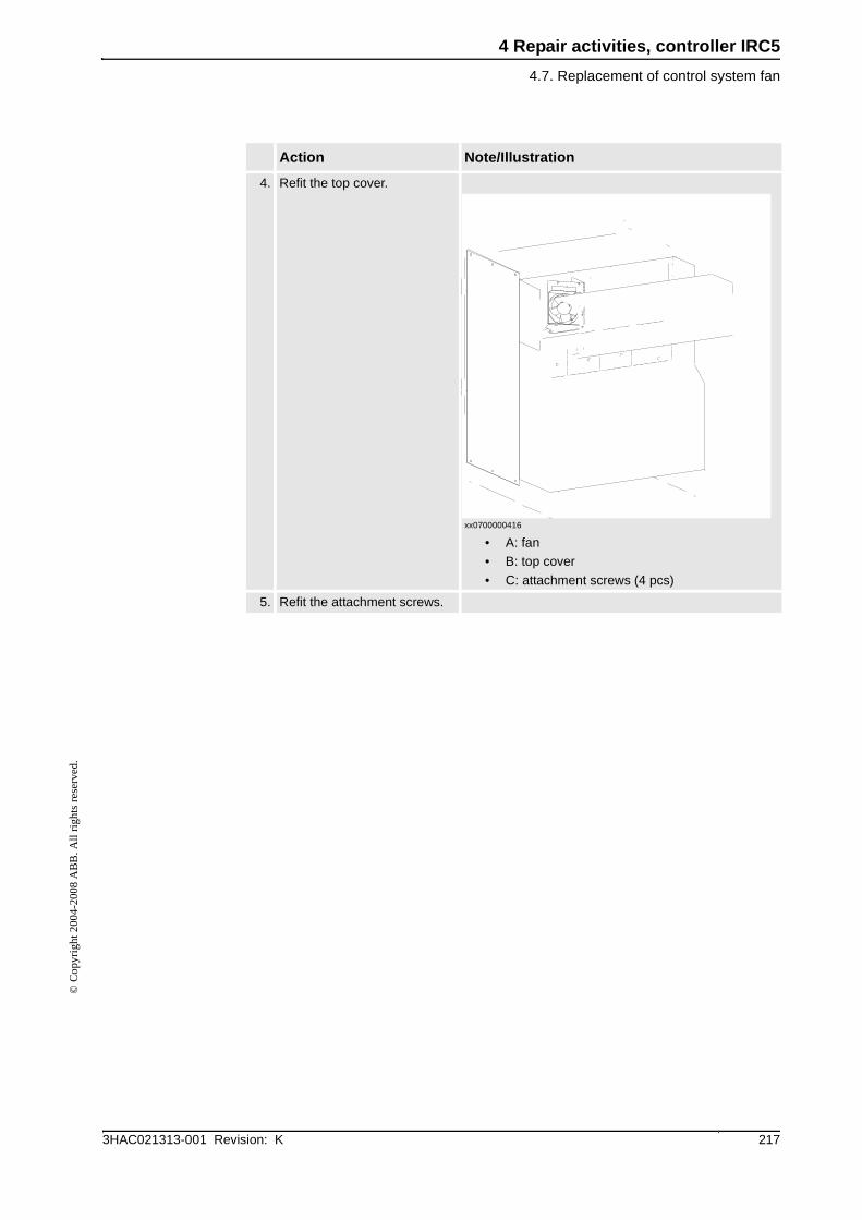
4. Refit the top cover.
xx0700000416
• A: fan
• B: top cover
• C: attachment screws (4 pcs)
5. Refit the attachment screws.
Action Note/Illustration

4 Repair activities, controller IRC5
4.8. Replacement of heat exchange unit and fan
3HAC021313-001 Revision: K218
© C
opyr
ight
200
4-20
08 A
BB
. All
righ
ts r
eser
ved.
4.8. Replacement of heat exchange unit and fan
Location
The heat exchanger unit is located in the back of the Control Module as shown below. On the
Dual Cabinet Controller the heat exchange unit is located on the Control Module.
xx0500001952
Required equipment
A Fan
B Heat exchanger
C Top cover
D Attachment screws (4 pcs)
4 Repair activities, controller IRC5
4.8. Replacement of heat exchange unit and fan
2193HAC021313-001 Revision: K
© C
opyr
ight
200
4-20
08 A
BB
. All
righ
ts r
eser
ved.
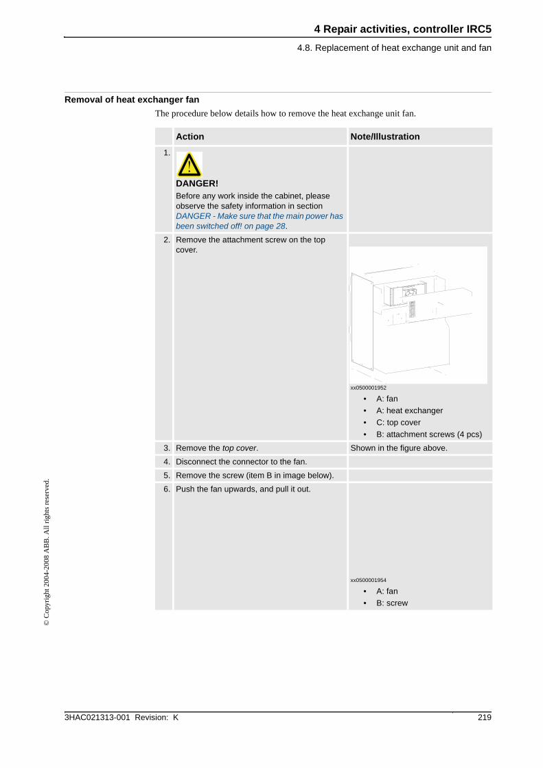
Removal of heat exchanger fan
The procedure below details how to remove the heat exchange unit fan.
Action Note/Illustration
1.
DANGER!Before any work inside the cabinet, please observe the safety information in section DANGER - Make sure that the main power has been switched off! on page 28.
2. Remove the attachment screw on the top cover.
xx0500001952
• A: fan
• A: heat exchanger
• C: top cover
• B: attachment screws (4 pcs)
3. Remove the top cover. Shown in the figure above.
4. Disconnect the connector to the fan.
5. Remove the screw (item B in image below).
6. Push the fan upwards, and pull it out.
xx0500001954
• A: fan
• B: screw

4 Repair activities, controller IRC5
4.8. Replacement of heat exchange unit and fan
3HAC021313-001 Revision: K220
© C
opyr
ight
200
4-20
08 A
BB
. All
righ
ts r
eser
ved.
Refitting of heat exchanger fan
The procedure below details how to refit the heat exchange unit fan.
Replacement of heat exchange unit
The procedure below details how to remove the heat exchange unit.
Action Note/Illustration
1. Put the new fan in place, and push down.
xx0500001954
• A: fan
• B: screw
2. Refit the screw (item B in image above).
3. Reconnect the connector to fan.
4. Refit the top cover.
xx0500001952
• A: fan
• B: heat exchanger
• C: top cover
• B: attachment screws (4 pcs)
5. Refit the attachment screws Shown in the figure above.

4 Repair activities, controller IRC5
4.8. Replacement of heat exchange unit and fan
2213HAC021313-001 Revision: K
© C
opyr
ight
200
4-20
08 A
BB
. All
righ
ts r
eser
ved.
2. Follow step 2 through 5 in Removal of heat exchanger fan on page 219.
3. Mark the placement of the heat exchange unit with a pen before removal.
4. Use a chisel and a hammer to wedge between the heat exchange unit and cabinet wall in all four coners of the heat exchanger.
xx0600002677
• A: chisel
• B: heat exchange unit
5. Remove the exchanger unit.
6. Apply the adhesive on a cleaned and dry surface on the new heat exchanger unit.
xx0600002678
• A: heat exchange unit
• B: adhesive run
7. Fit the new heat exchange unit within 20min. It could be necessary to fixate the unit in position until the adhesive is hard.
8. Follow the step 1 to 4 in Refitting of heat exchanger fan on page 220.
Action Note/Illustration
AB
A
B
Continued

4 Repair activities, controller IRC5
4.22. Replacement of servo drive units, rectifierand capacitorunit
2793HAC021313-001 Revision: K
© C
opyr
ight
200
4-20
08 A
BB
. All
righ
ts r
eser
ved.
4.22. Replacement of servo drive units, rectifierand capacitorunit
Location
The illustration below shows the location of the servo drive units, rectifiers and capacitor
units in a Single Cabinet Controller.
In the Dual Cabinet Controller the servo drive components are located in the Drive Module.
xx0500001858
Configuration
The drive module exists in a number of versions, these are described in section Configuration
of the drive system, IRC5 on page 88
Required equipment
A Operator’s panel
B Capacitor
C Computer unit
D Panel board unit
E Axis computer
F Drive system ( drive units and rectifier)

4 Repair activities, controller IRC5
4.22. Replacement of servo drive units, rectifierand capacitorunit
3HAC021313-001 Revision: K280
© C
opyr
ight
200
4-20
08 A
BB
. All
righ
ts r
eser
ved.
Removal
The procedure below details how to remove the servo drive units, rectifiers and capacitor
units.
Other tools and procedures may be required. See references to these procedures in the step-by-step instructions below.
These procedures include references to the tools required.
Circuit Diagram See Circuit Diagram on page 341.
Equipment Note
Action Note/Illustration
1.
DANGER!Before any work inside the cabinet, please observe the safety information in section DANGER - Make sure that the main power has been switched off! on page 28.
2. If an EPS board (option Electronic Position Switches) is mounted the Axis computer unit needs to be removed before removal of the servo drive units, rectifiers and capacitors.
See Replacement of EPS board DSQC 646 on page 285.
3. Disconnect all connectors from the unit to be replaced.
4. Remove the busbar between units.
xx0400000998
Parts:
• A: bus bar
ContinuedContinues on next page
4 Repair activities, controller IRC5
4.22. Replacement of servo drive units, rectifierand capacitorunit
2813HAC021313-001 Revision: K
© C
opyr
ight
200
4-20
08 A
BB
. All
righ
ts r
eser
ved.
Refitting
The procedure below details how to refit the servo drive units, rectifiers and capacitor units.
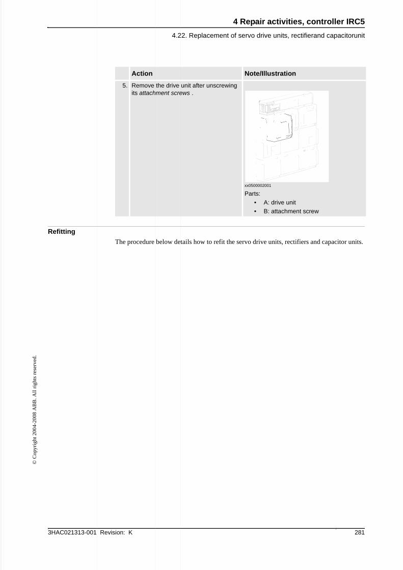
5. Remove the drive unit after unscrewing its attachment screws .
xx0500002001
Parts:
• A: drive unit
• B: attachment screw
Action Note/Illustration
A
c
t
i
o
n
N
o
t
e
/
I
l
l
u
s
t
r
a
t
i
o
n
1
.
D
A
N
G
E
R
!
B
e
f
o
r
e
a
n
y
w
o
r
k
i
n
s
i
d
e
t
h
e
c
a
b
i
n
e
t
,
p
l
e
a
s
e
o
b
s
e
r
v
e
t
h
e
s
a
f
e
t
y
in
f
o
r
m
a
t
io
n
in
s
e
c
t
io
n
D
A
N
G
E
R
-
M
a
k
e
s
u
r
e
t
h
a
t
t
h
e
m
a
in
p
o
w
e
r
h
a
s
b
e
e
n
s
w
it
c
h
e
d
o
f
f
!
o
n
p
a
g
e
2
8
.
2
.
F
it
t
h
e
u
n
it
in
it
s
in
t
e
n
d
e
d
p
o
s
it
io
n
a
n
d
o
r
ie
n
t
a
t
io
n
.
S
e
c
u
r
e
it
w
it
h
it
s
a
t
t
a
c
h
m
e
n
t
s
c
r
e
w
s
.
3
.
R
e
c
o
n
n
e
c
t
a
ll
b
u
s
b
a
r
s
b
e
t
w
e
e
n
u
n
it
s
.
4
.
R
e
c
o
n
n
e
c
t
a
n
y
c
o
n
n
e
c
t
o
r
s
d
is
c
o
n
n
e
c
t
e
d
a
t
r
e
m
o
v
a
l.
5
.
R
e
f
it
t
h
e
A
x
is
c
o
m
p
u
t
e
r
u
n
it
if
E
P
S
b
o
a
r
d
is
m
o
u
n
t
e
d

4 Repair activities, controller IRC5
4.28. Replacement of drive system fans
3HAC021313-001 Revision: K300
© C
opyr
ight
200
4-20
08 A
BB
. All
righ
ts r
eser
ved.
4.28. Replacement of drive system fans
Location
The illustration below shows the drive system fans in the Single Cabinet Controller.
In the Dual Cabinet Controller the drive system fans are located in the back of the Drive
Module.
xx0500002011
Required equipment
A Fan (4 pcs)
B Cover
C Attachment screw (4 pcs)
A
B
C
Equipment
Note
Fan with.receptacleSee Miscellaneous parts on page 326.Standard toolkitThe contents are defined in section Standard toolkit.Other tools and procedures may be required. see references to these procedures in the step-by-step instructions below.These procedures include references to the tools required.Circuit diagramSee Circuit Diagram on page 341.
Continues on next page

4 Repair activities, controller IRC5
4.28. Replacement of drive system fans
3013HAC021313-001 Revision: K
© C
opyr
ight
200
4-20
08 A
BB
. All
righ
ts r
eser
ved.
Removal
The following procedures details how to remove the drive system fan.
Refitting
The following procedures details how to refit the drive system fan.
Action Note /illustration
1.
DANGER!Before any work inside the cabinet, please

4 Repair activities, controller IRC5
4.28. Replacement of drive system fans
3HAC021313-001 Revision: K302
© C
opyr
ight
200
4-20
08 A
BB
. All
righ
ts r
eser
ved.
2. Reconnect the connector to the fan.
3. Refit the fan by placing the attachments in the back of the fan housing in the grooves.
xx0500002015
• A: fan
• B: attachments
• C: grooves
4. Refit the cover and the attachment screws.
5. Refit the moist dust filter magazine. (Option)
How to refit the moist dust filter magazine is detailed in section Replacement of moist dust filter on page 173.
Action Note/illustration
Continued