3GPP TS 36 - honorcup.ruhonorcup.ru/upload/iblock/5d5/5d5271e08494dab8ebe1b5c1c3da7305.… · GSM...
109
Release 11 3GPP 3GPP TS 36.101 V11.9.0 (2014-06) 15 Foreword This Technical Specification (TS) has been produced by the 3 rd Generation Partnership Project (3GPP). The contents of the present document are subject to continuing work within the TSG and may change following formal TSG approval. Should the TSG modify the contents of the present document, it will be re-released by the TSG with an identifying change of release date and an increase in version number as follows: Version x.y.z Where: x the first digit: 1 presented to TSG for information; 2 presented to TSG for approval; 3 or greater indicates TSG approved document under change control. y the second digit is incremented for all changes of substance, i.e. technical enhancements, corrections, updates, etc. z the third digit is incremented when editorial only changes have been incorporated in the document.
Transcript of 3GPP TS 36 - honorcup.ruhonorcup.ru/upload/iblock/5d5/5d5271e08494dab8ebe1b5c1c3da7305.… · GSM...

Release 11
3GPP
3GPP TS 36.101 V11.9.0 (2014-06) 15
Foreword
This Technical Specification (TS) has been produced by the 3rd
Generation Partnership Project (3GPP).
The contents of the present document are subject to continuing work within the TSG and may change following formal
TSG approval. Should the TSG modify the contents of the present document, it will be re-released by the TSG with an
identifying change of release date and an increase in version number as follows:
Version x.y.z
Where:
x the first digit:
1 presented to TSG for information;
2 presented to TSG for approval;
3 or greater indicates TSG approved document under change control.
y the second digit is incremented for all changes of substance, i.e. technical enhancements, corrections,
updates, etc.
z the third digit is incremented when editorial only changes have been incorporated in the document.
Release 11
3GPP
3GPP TS 36.101 V11.9.0 (2014-06) 16
1 Scope
. The present document establishes the minimum RF characteristics and minimum performance requirements for E-
UTRA User Equipment (UE).
2 References
The following documents contain provisions which, through reference in this text, constitute provisions of the present
document.
- References are either specific (identified by date of publication, edition number, version number, etc.) or non-specific.
- For a specific reference, subsequent revisions do not apply.
- For a non-specific reference, the latest version applies. In the case of a reference to a 3GPP document (including a
GSM document), a non-specific reference implicitly refers to the latest version of that document in the same Release as
the present document.
[1] 3GPP TR 21.905: "Vocabulary for 3GPP Specifications".
[2] ITU-R Recommendation SM.329-10, "Unwanted emissions in the spurious domain"
[3] ITU-R Recommendation M.1545: "Measurement uncertainty as it applies to test limits for the
terrestrial component of International Mobile Telecommunications-2000".
[4] 3GPP TS 36.211: "Physical Channels and Modulation".
[5] 3GPP TS 36.212: "Multiplexing and channel coding".
[6] 3GPP TS 36.213: "Physical layer procedures".
[7] 3GPP TS 36.331: " Requirements for support of radio resource management ".
[8] 3GPP TS 36.307: " Requirements on User Equipments (UEs) supporting a release-independent
frequency band".
[9] 3GPP TS 36.423: "X2 application protocol (X2AP) ".
3 Definitions, symbols and abbreviations
3.1 Definitions
For the purposes of the present document, the terms and definitions given in TR 21.905 [1] and the following apply in
the case of a single component carrier. A term defined in the present document takes precedence over the definition of
the same term, if any, in TR 21.905 [1].
Aggregated Channel Bandwidth: The RF bandwidth in which a UE transmits and receives multiple contiguously
aggregated carriers.
Aggregated Transmission Bandwidth Configuration: The number of resource block allocated within the aggregated
channel bandwidth.
Carrier aggregation: Aggregation of two or more component carriers in order to support wider transmission
bandwidths.
Carrier aggregation band: A set of one or more operating bands across which multiple carriers are aggregated with a
specific set of technical requirements.

Release 11
3GPP
3GPP TS 36.101 V11.9.0 (2014-06) 17
Carrier aggregation bandwidth class: A class defined by the aggregated transmission bandwidth configuration and
maximum number of component carriers supported by a UE.
Carrier aggregation configuration: A combination of CA operating band(s) and CA bandwidth class(es) supported by
a UE.
Channel edge: The lowest and highest frequency of the carrier, separated by the channel bandwidth.
Channel bandwidth: The RF bandwidth supporting a single E-UTRA RF carrier with the transmission bandwidth
configured in the uplink or downlink of a cell. The channel bandwidth is measured in MHz and is used as a reference
for transmitter and receiver RF requirements.
Contiguous carriers: A set of two or more carriers configured in a spectrum block where there are no RF requirements
based on co-existence for un-coordinated operation within the spectrum block.
Contiguous resource allocation: A resource allocation of consecutive resource blocks within one carrier or across
contiguously aggregated carriers. The gap between contiguously aggregated carriers due to the nominal channel spacing
is allowed.
Contiguous spectrum: Spectrum consisting of a contiguous block of spectrum with no sub-block gaps.
Enhanced performance requirements type A: This defines performance requirements assuming as baseline receiver
reference symbol based linear minimum mean square error interference rejection combining.
Inter-band carrier aggregation: Carrier aggregation of component carriers in different operating bands.
NOTE: Carriers aggregated in each band can be contiguous or non-contiguous.
Intra-band contiguous carrier aggregation: Contiguous carriers aggregated in the same operating band.
Intra-band non-contiguous carrier aggregation: Non-contiguous carriers aggregated in the same operating band.
Lower sub-block edge: The frequency at the lower edge of one sub-block. It is used as a frequency reference point for
both transmitter and receiver requirements.
Non-contiguous spectrum: Spectrum consisting of two or more sub-blocks separated by sub-block gap(s).
Sub-block: This is one contiguous allocated block of spectrum for transmission and reception by the same UE. There
may be multiple instances of sub-blocks within an RF bandwidth.
Sub-block bandwidth: The bandwidth of one sub-block.
Sub-block gap: A frequency gap between two consecutive sub-blocks within an RF bandwidth, where the RF
requirements in the gap are based on co-existence for un-coordinated operation.
Synchronized operation: Operation of TDD in two different systems, where no simultaneous uplink and downlink
occur.
Unsynchronized operation: Operation of TDD in two different systems, where the conditions for synchronized
operation are not met.
Upper sub-block edge: The frequency at the upper edge of one sub-block. It is used as a frequency reference point for
both transmitter and receiver requirements.
3.2 Symbols
For the purposes of the present document, the following symbols apply:
BWChannel Channel bandwidth
BWChannel,block Sub-block bandwidth, expressed in MHz. BWChannel,block= Fedge,block,high- Fedge,block,low.
BWChannel_CA Aggregated channel bandwidth, expressed in MHz.
BWGB Virtual guard band to facilitate transmitter (receiver) filtering above / below edge CCs.

Release 11
3GPP
3GPP TS 36.101 V11.9.0 (2014-06) 18
RSE Transmitted energy per RE for reference symbols during the useful part of the symbol, i.e.
excluding the cyclic prefix, (average power normalized to the subcarrier spacing) at the eNode B
transmit antenna connector
sE The averaged received energy per RE of the wanted signal during the useful part of the symbol,
i.e. excluding the cyclic prefix, at the UE antenna connector; average power is computed within a
set of REs used for the transmission of physical channels (including user specific RSs when
present), divided by the number of REs within the set, and normalized to the subcarrier spacing
F Frequency
FInterferer (offset) Frequency offset of the interferer
FInterferer Frequency of the interferer
FC Frequency of the carrier centre frequency
FC,block, high Center frequency of the highest transmitted/received carrier in a sub-block.
FC,block, low Center frequency of the lowest transmitted/received carrier in a sub-block.
FCA_low The centre frequency of the lowest carrier, expressed in MHz.
FCA_high The centre frequency of the highest carrier, expressed in MHz.
FDL_low The lowest frequency of the downlink operating band
FDL_high The highest frequency of the downlink operating band
FUL_low The lowest frequency of the uplink operating band
FUL_high The highest frequency of the uplink operating band
Fedge,block,low The lower sub-block edge, where Fedge,block,low = FC,block,low - Foffset.
Fedge,block,high The upper sub-block edge, where Fedge,block,high = FC,block,high + Foffset.
Fedge_low The lower edge of aggregated channel bandwidth, expressed in MHz.
Fedge_high The higher edge of aggregated channel bandwidth, expressed in MHz.
Foffset Frequency offset from FC_high to the higher edge or FC_low to the lower edge.
Foffset,block,low Separation between lower edge of a sub-block and the center of the lowest component carrier
within the sub-block
Foffset,block,high Separation between higher edge of a sub-block and the center of the highest component carrier
within the sub-block
FOOB The boundary between the E-UTRA out of band emission and spurious emission domains.
oI The power spectral density of the total input signal (power averaged over the useful part of the
symbols within the transmission bandwidth configuration, divided by the total number of RE for
this configuration and normalised to the subcarrier spacing) at the UE antenna connector,
including the own-cell downlink signal
orI The total transmitted power spectral density of the own-cell downlink signal (power averaged over
the useful part of the symbols within the transmission bandwidth configuration, divided by the
total number of RE for this configuration and normalised to the subcarrier spacing) at the eNode B
transmit antenna connector
orI The total received power spectral density of the own-cell downlink signal (power averaged over
the useful part of the symbols within the transmission bandwidth configuration, divided by the
total number of RE for this configuration and normalised to the subcarrier spacing) at the UE
antenna connector
otI The received power spectral density of the total noise and interference for a certain RE (average
power obtained within the RE and normalized to the subcarrier spacing) as measured at the UE
antenna connector
LCRB Transmission bandwidth which represents the length of a contiguous resource block allocation
expressed in units of resources blocks
Ncp Cyclic prefix length
NDL Downlink EARFCN
ocN The power spectral density of a white noise source (average power per RE normalised to the
subcarrier spacing), simulating interference from cells that are not defined in a test procedure, as
measured at the UE antenna connector
1ocN The power spectral density of a white noise source (average power per RE normalized to the
subcarrier spacing), simulating interference in non-CRS symbols in ABS subframe from cells that
are not defined in a test procedure, as measured at the UE antenna connector.
2ocN The power spectral density of a white noise source (average power per RE normalized to the
subcarrier spacing), simulating interference in CRS symbols in ABS subframe from all cells that
are not defined in a test procedure, as measured at the UE antenna connector.

Release 11
3GPP
3GPP TS 36.101 V11.9.0 (2014-06) 19
3ocN The power spectral density of a white noise source (average power per RE normalised to the
subcarrier spacing), simulating interference in non-ABS subframe from cells that are not defined
in a test procedure, as measured at the UE antenna connector
´ocN The power spectral density (average power per RE normalised to the subcarrier spacing) of the
summation of the received power spectral densities of the strongest interfering cells explicitly
defined in a test procedure plus, as measured at the UE antenna connector. The respective power
spectral density of each interfering cell relative to is defined by its associated DIP value.
NOffs-DL Offset used for calculating downlink EARFCN
NOffs-UL Offset used for calculating uplink EARFCN
otxN The power spectral density of a white noise source (average power per RE normalised to the
subcarrier spacing) simulating eNode B transmitter impairments as measured at the eNode B
transmit antenna connector
NRB Transmission bandwidth configuration, expressed in units of resource blocks
NRB_agg Aggregated Transmission Bandwidth Configuration The number of the aggregated RBs within the
fully allocated Aggregated Channel bandwidth.
NRB_alloc Total number of simultaneously transmitted resource blocks in Channel bandwidth or Aggregated
Channel Bandwidth.
NUL Uplink EARFCN.
Rav Minimum average throughput per RB.
PCMAX The configured maximum UE output power.
PCMAX, c The configured maximum UE output power for serving cell c.
PEMAX Maximum allowed UE output power signalled by higher layers. Same as IE P-Max, defined in [7].
PEMAX, c Maximum allowed UE output power signalled by higher layers for serving cell c. Same as IE
P-Max, defined in [7].
PInterferer Modulated mean power of the interferer
PPowerClass PPowerClass is the nominal UE power (i.e., no tolerance).
PUMAX The measured configured maximum UE output power.
Puw Power of an unwanted DL signal
Pw Power of a wanted DL signal
RBstart Indicates the lowest RB index of transmitted resource blocks.
RBend Indicates the highest RB index of transmitted resource blocks.
ΔfOOB Δ Frequency of Out Of Band emission.
ΔRIB,c Allowed reference sensitivity relaxation due to support for inter-band CA operation, for serving
cell c.
ΔTIB,c Allowed maximum configured output power relaxation due to support for inter-band CA
operation, for serving cell c.
TC Allowed operating band edge transmission power relaxation.
TC,c Allowed operating band edge transmission power relaxation for serving cell c.
Test specific auxiliary variable used for the purpose of downlink power allocation, defined in
Annex C.3.2.
Wgap Sub-block gap size
3.3 Abbreviations
For the purposes of the present document, the abbreviations given in TR 21.905 [1] and the following apply. An
abbreviation defined in the present document takes precedence over the definition of the same abbreviation, if any, in
TR 21.905 [1].
ABS Almost Blank Subframe
ACLR Adjacent Channel Leakage Ratio
ACS Adjacent Channel Selectivity
A-MPR Additional Maximum Power Reduction
AWGN Additive White Gaussian Noise
BS Base Station
CA Carrier Aggregation
CA_X CA for band X where X is the applicable E-UTRA operating band
CA_X-X Non-contiguous intra band CA for band X where X is the applicable E-UTRA operating band
CA_X-Y CA for band X and Band Y where X and Y are the applicable E-UTRA operating band
CC Component Carriers
Release 11
3GPP
3GPP TS 36.101 V11.9.0 (2014-06) 20
CPE Customer Premise Equipment
CPE_X Customer Premise Equipment for E-UTRA operating band X
CW Continuous Wave
DL Downlink
DIP Dominant Interferer Proportion
eDL-MIMO Down Link Multiple Antenna transmission
EARFCN E-UTRA Absolute Radio Frequency Channel Number
EPRE Energy Per Resource Element
E-UTRA Evolved UMTS Terrestrial Radio Access
EUTRAN Evolved UMTS Terrestrial Radio Access Network
EVM Error Vector Magnitude
FDD Frequency Division Duplex
FRC Fixed Reference Channel
HD-FDD Half- Duplex FDD
MCS Modulation and Coding Scheme
MOP Maximum Output Power
MPR Maximum Power Reduction
MSD Maximum Sensitivity Degradation
OCNG OFDMA Channel Noise Generator
OFDMA Orthogonal Frequency Division Multiple Access
OOB Out-of-band
PA Power Amplifier
PCC Primary Component Carrier
P-MPR Power Management Maximum Power Reduction
PSS Primary Synchronization Signal
PSS_RA PSS-to-RS EPRE ratio for the channel PSS
RE Resource Element
REFSENS Reference Sensitivity power level
r.m.s Root Mean Square
SCC Secondary Component Carrier
SINR Signal-to-Interference-and-Noise Ratio
SNR Signal-to-Noise Ratio
SSS Secondary Synchronization Signal
SSS_RA SSS-to-RS EPRE ratio for the channel SSS
TDD Time Division Duplex
UE User Equipment
UL Uplink
UL-MIMO Up Link Multiple Antenna transmission
UMTS Universal Mobile Telecommunications System
UTRA UMTS Terrestrial Radio Access
UTRAN UMTS Terrestrial Radio Access Network
xCH_RA xCH-to-RS EPRE ratio for the channel xCH in all transmitted OFDM symbols not containing RS
xCH_RB xCH-to-RS EPRE ratio for the channel xCH in all transmitted OFDM symbols containing RS
4 General
4.1 Relationship between minimum requirements and test requirements
The Minimum Requirements given in this specification make no allowance for measurement uncertainty. The test
specification TS 36.521-1 Annex F defines Test Tolerances. These Test Tolerances are individually calculated for each
test. The Test Tolerances are used to relax the Minimum Requirements in this specification to create Test Requirements.
The measurement results returned by the Test System are compared - without any modification - against the Test
Requirements as defined by the shared risk principle.
The Shared Risk principle is defined in ITU-R M.1545 [3].

Release 11
3GPP
3GPP TS 36.101 V11.9.0 (2014-06) 21
4.2 Applicability of minimum requirements
a) In this specification the Minimum Requirements are specified as general requirements and additional
requirements. Where the Requirement is specified as a general requirement, the requirement is mandated to be
met in all scenarios
b) For specific scenarios for which an additional requirement is specified, in addition to meeting the general
requirement, the UE is mandated to meet the additional requirements.
c) The reference sensitivity power levels defined in subclause 7.3 are valid for the specified reference measurement
channels.
d) Note: Receiver sensitivity degradation may occur when:
1) The UE simultaneously transmits and receives with bandwidth allocations less than the transmission
bandwidth configuration (see Figure 5.6-1), and
2) Any part of the downlink transmission bandwidth is within an uplink transmission bandwidth from the
downlink center subcarrier.
e) The spurious emissions power requirements are for the long term average of the power. For the purpose of
reducing measurement uncertainty it is acceptable to average the measured power over a period of time
sufficient to reduce the uncertainty due to the statistical nature of the signal.
4.3 Void
4.3A Applicability of minimum requirements (CA, UL-MIMO, eDL-MIMO)
The requirements in clauses 5, 6 and 7 which are specific to CA, UL-MIMO, and eDL-MIMO are specified as suffix A,
B, C, D where;
a) Suffix A additional requirements need to support CA
b) Suffix B additional requirements need to support UL-MIMO
c) Suffix C additional requirements need to support TBD
d) Suffix D additional requirements need to support eDL-MIMO
A terminal which supports the above features needs to meet both the general requirements and the additional
requirement applicable to the additional subclause (suffix A, B, C and D) in clauses 5, 6 and 7. Where there is a
difference in requirement between the general requirements and the additional subclause requirements (suffix A, B, C
and D) in clauses 5, 6 and 7, the tighter requirements are applicable unless stated otherwise in the additional subclause.
A terminal which supports more than one feature (CA, UL-MIMO, and eDL-MIMO) in clauses 5, 6 and 7 shall meet all
of the separate corresponding requirements.
For a terminal supporting CA, compliance with minimum requirements for non-contiguous intra-band carrier
aggregation in any given operating band does not imply compliance with minimum requirements for contiguous intra-
band carrier aggregation in the same operating band.
For a terminal supporting CA, compliance with minimum requirements for contiguous intra-band carrier aggregation in
any given operating band does not imply compliance with minimum requirements for non- contiguous intra-band carrier
aggregation in the same operating band.
4.4 RF requirements in later releases
The standardisation of new frequency bands may be independent of a release. However, in order to implement a UE that
conforms to a particular release but supports a band of operation that is specified in a later release, it is necessary to
Release 11
3GPP
3GPP TS 36.101 V11.9.0 (2014-06) 22
specify some extra requirements. TS 36.307 [8] specifies requirements on UEs supporting a frequency band that is
independent of release.
NOTE: For terminals conforming to the 3GPP release of the present document, some RF requirements in later
releases may be mandatory independent of whether the UE supports the bands specified in later releases
or not. The set of requirements from later releases that is also mandatory for UEs conforming to the 3GPP
release of the present document is determined by regional regulation.
5 Operating bands and channel arrangement
5.1 General
The channel arrangements presented in this clause are based on the operating bands and channel bandwidths defined in
the present release of specifications.
NOTE: Other operating bands and channel bandwidths may be considered in future releases.
5.2 Void
5.3 Void
5.4 Void
5.5 Operating bands
E-UTRA is designed to operate in the operating bands defined in Table 5.5-1.

Release 11
3GPP
3GPP TS 36.101 V11.9.0 (2014-06) 23
Table 5.5-1 E-UTRA operating bands
E-UTRA Operating
Band
Uplink (UL) operating band BS receive UE transmit
Downlink (DL) operating band BS transmit UE receive
Duplex Mode
FUL_low – FUL_high FDL_low – FDL_high
1 1920 MHz – 1980 MHz 2110 MHz – 2170 MHz FDD
2 1850 MHz – 1910 MHz 1930 MHz – 1990 MHz FDD
3 1710 MHz – 1785 MHz 1805 MHz – 1880 MHz FDD
4 1710 MHz – 1755 MHz 2110 MHz – 2155 MHz FDD
5 824 MHz – 849 MHz 869 MHz – 894MHz FDD
61 830 MHz – 840 MHz 875 MHz – 885 MHz FDD
7 2500 MHz – 2570 MHz 2620 MHz – 2690 MHz FDD
8 880 MHz – 915 MHz 925 MHz – 960 MHz FDD
9 1749.9 MHz – 1784.9 MHz 1844.9 MHz – 1879.9 MHz FDD
10 1710 MHz – 1770 MHz 2110 MHz – 2170 MHz FDD
11 1427.9 MHz – 1447.9 MHz 1475.9 MHz – 1495.9 MHz FDD
12 699 MHz – 716 MHz 729 MHz – 746 MHz FDD
13 777 MHz – 787 MHz 746 MHz – 756 MHz FDD
14 788 MHz – 798 MHz 758 MHz – 768 MHz FDD
15 Reserved Reserved FDD
16 Reserved Reserved FDD
17 704 MHz – 716 MHz 734 MHz – 746 MHz FDD
18 815 MHz – 830 MHz 860 MHz – 875 MHz FDD
19 830 MHz – 845 MHz 875 MHz – 890 MHz FDD
20 832 MHz – 862 MHz 791 MHz – 821 MHz FDD
21 1447.9 MHz – 1462.9 MHz 1495.9 MHz – 1510.9 MHz FDD
22 3410 MHz – 3490 MHz 3510 MHz – 3590 MHz FDD
23 2000 MHz – 2020 MHz 2180 MHz – 2200 MHz FDD
24 1626.5 MHz – 1660.5 MHz 1525 MHz – 1559 MHz FDD
25 1850 MHz – 1915 MHz 1930 MHz – 1995 MHz FDD
26 814 MHz – 849 MHz 859 MHz – 894 MHz FDD
27 807 MHz – 824 MHz 852 MHz – 869 MHz FDD
28 703 MHz – 748 MHz 758 MHz – 803 MHz FDD
29 N/A 717 MHz – 728 MHz FDD2
...
33 1900 MHz – 1920 MHz 1900 MHz – 1920 MHz TDD
34 2010 MHz – 2025 MHz 2010 MHz – 2025 MHz TDD
35 1850 MHz – 1910 MHz 1850 MHz – 1910 MHz TDD
36 1930 MHz – 1990 MHz 1930 MHz – 1990 MHz TDD
37 1910 MHz – 1930 MHz 1910 MHz – 1930 MHz TDD
38 2570 MHz – 2620 MHz 2570 MHz – 2620 MHz TDD
39 1880 MHz – 1920 MHz 1880 MHz – 1920 MHz TDD
40 2300 MHz – 2400 MHz 2300 MHz – 2400 MHz TDD
41 2496 MHz 2690 MHz 2496 MHz 2690 MHz TDD
42 3400 MHz – 3600 MHz 3400 MHz – 3600 MHz TDD
43 3600 MHz – 3800 MHz 3600 MHz – 3800 MHz TDD
44 703 MHz – 803 MHz 703 MHz – 803 MHz TDD
NOTE 1: Band 6 is not applicable NOTE 2: Restricted to E-UTRA operation when carrier aggregation is configured. The
downlink operating band is paired with the uplink operating band (external) of the carrier aggregation configuration that is supporting the configured Pcell.
5.5A Operating bands for CA
E-UTRA carrier aggregation is designed to operate in the operating bands defined in Tables 5.5A-1 and 5.5A-2.
Release 11
3GPP
3GPP TS 36.101 V11.9.0 (2014-06) 24
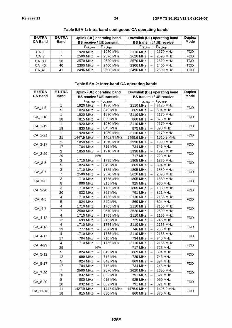
Table 5.5A-1: Intra-band contiguous CA operating bands
E-UTRA CA Band
E-UTRA Band
Uplink (UL) operating band Downlink (DL) operating band Duplex Mode BS receive / UE transmit BS transmit / UE receive
FUL_low – FUL_high FDL_low – FDL_high
CA_1 1 1920 MHz – 1980 MHz 2110 MHz – 2170 MHz FDD
CA_7 7 2500 MHz – 2570 MHz 2620 MHz – 2690 MHz FDD
CA_38 38 2570 MHz – 2620 MHz 2570 MHz – 2620 MHz TDD
CA_40 40 2300 MHz – 2400 MHz 2300 MHz – 2400 MHz TDD
CA_41 41 2496 MHz 2690 MHz 2496 MHz 2690 MHz TDD
Table 5.5A-2: Inter-band CA operating bands
E-UTRA CA Band
E-UTRA Band
Uplink (UL) operating band Downlink (DL) operating band Duplex Mode BS receive / UE transmit BS transmit / UE receive
FUL_low – FUL_high FDL_low – FDL_high
CA_1-5 1 1920 MHz – 1980 MHz 2110 MHz – 2170 MHz
FDD 5 824 MHz – 849 MHz 869 MHz – 894 MHz
CA_1-18 1 1920 MHz – 1980 MHz 2110 MHz – 2170 MHz
FDD 18 815 MHz – 830 MHz 860 MHz – 875 MHz
CA_1-19 1 1920 MHz – 1980 MHz 2110 MHz – 2170 MHz
FDD 19 830 MHz – 845 MHz 875 MHz – 890 MHz
CA_1-21 1 1920 MHz – 1980 MHz 2110 MHz – 2170 MHz
FDD 21 1447.9 MHz – 1462.9 MHz 1495.9 MHz – 1510.9 MHz
CA_2-17 2 1850 MHz – 1910 MHz 1930 MHz – 1990 MHz
FDD 17 704 MHz – 716 MHz 734 MHz – 746 MHz
CA_2-29 2 1850 MHz – 1910 MHz 1930 MHz – 1990 MHz
FDD 29 N/A 717 MHz – 728 MHz
CA_3-5 3 1710 MHz – 1785 MHz 1805 MHz – 1880 MHz
FDD 5 824 MHz – 849 MHz 869 MHz – 894 MHz
CA_3-7 3 1710 MHz – 1785 MHz 1805 MHz – 1880 MHz
FDD 7 2500 MHz – 2570 MHz 2620 MHz – 2690 MHz
CA_3-8 3 1710 MHz 1785 MHz 1805 MHz 1880 MHz
FDD 8 880 MHz 915 MHz 925 MHz 960 MHz
CA_3-20 3 1710 MHz – 1785 MHz 1805 MHz – 1880 MHz
FDD 20 832 MHz – 862 MHz 791 MHz – 821 MHz
CA_4-5 4 1710 MHz – 1755 MHz 2110 MHz – 2155 MHz
FDD 5 824 MHz – 849 MHz 869 MHz – 894 MHz
CA_4-7 4 1710 MHz 1755 MHz 2110 MHz 2155 MHz
FDD 7 2500 MHz 2570 MHz 2620 MHz 2690 MHz
CA_4-12 4 1710 MHz – 1755 MHz 2110 MHz – 2155 MHz
FDD 12 699 MHz – 716 MHz 729 MHz – 746 MHz
CA_4-13 4 1710 MHz – 1755 MHz 2110 MHz – 2155 MHz
FDD 13 777 MHz – 787 MHz 746 MHz – 756 MHz
CA_4-17 4 1710 MHz – 1755 MHz 2110 MHz – 2155 MHz
FDD 17 704 MHz – 716 MHz 734 MHz – 746 MHz
CA_4-29 4 1710 MHz – 1755 MHz 2110 MHz – 2155 MHz
FDD 29 N/A 717 MHz – 728 MHz
CA_5-12 5 824 MHz – 849 MHz 869 MHz – 894 MHz
FDD 12 699 MHz – 716 MHz 729 MHz – 746 MHz
CA_5-17 5 824 MHz – 849 MHz 869 MHz – 894 MHz
FDD 17 704 MHz – 716 MHz 734 MHz – 746 MHz
CA_7-20 7 2500 MHz – 2570 MHz 2620 MHz – 2690 MHz
FDD 20 832 MHz – 862 MHz 791 MHz – 821 MHz
CA_8-20 8 880 MHz – 915 MHz 925 MHz – 960 MHz
FDD 20 832 MHz – 862 MHz 791 MHz – 821 MHz
CA_11-18 11 1427.9 MHz – 1447.9 MHz 1475.9 MHz – 1495.9 MHz
FDD 18 815 MHz – 830 MHz 860 MHz – 875 MHz
Release 11
3GPP
3GPP TS 36.101 V11.9.0 (2014-06) 25
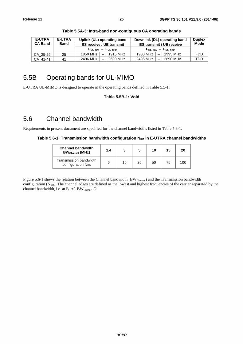
Table 5.5A-3: Intra-band non-contiguous CA operating bands
E-UTRA CA Band
E-UTRA Band
Uplink (UL) operating band Downlink (DL) operating band Duplex Mode BS receive / UE transmit BS transmit / UE receive
FUL_low – FUL_high FDL_low – FDL_high
CA_25-25 25 1850 MHz – 1915 MHz 1930 MHz – 1995 MHz FDD
CA_41-41 41 2496 MHz – 2690 MHz 2496 MHz – 2690 MHz TDD
5.5B Operating bands for UL-MIMO
E-UTRA UL-MIMO is designed to operate in the operating bands defined in Table 5.5-1.
Table 5.5B-1: Void
5.6 Channel bandwidth
Requirements in present document are specified for the channel bandwidths listed in Table 5.6-1.
Table 5.6-1: Transmission bandwidth configuration NRB in E-UTRA channel bandwidths
Channel bandwidth BWChannel [MHz]
1.4 3 5 10 15 20
Transmission bandwidth configuration NRB
6 15 25 50 75 100
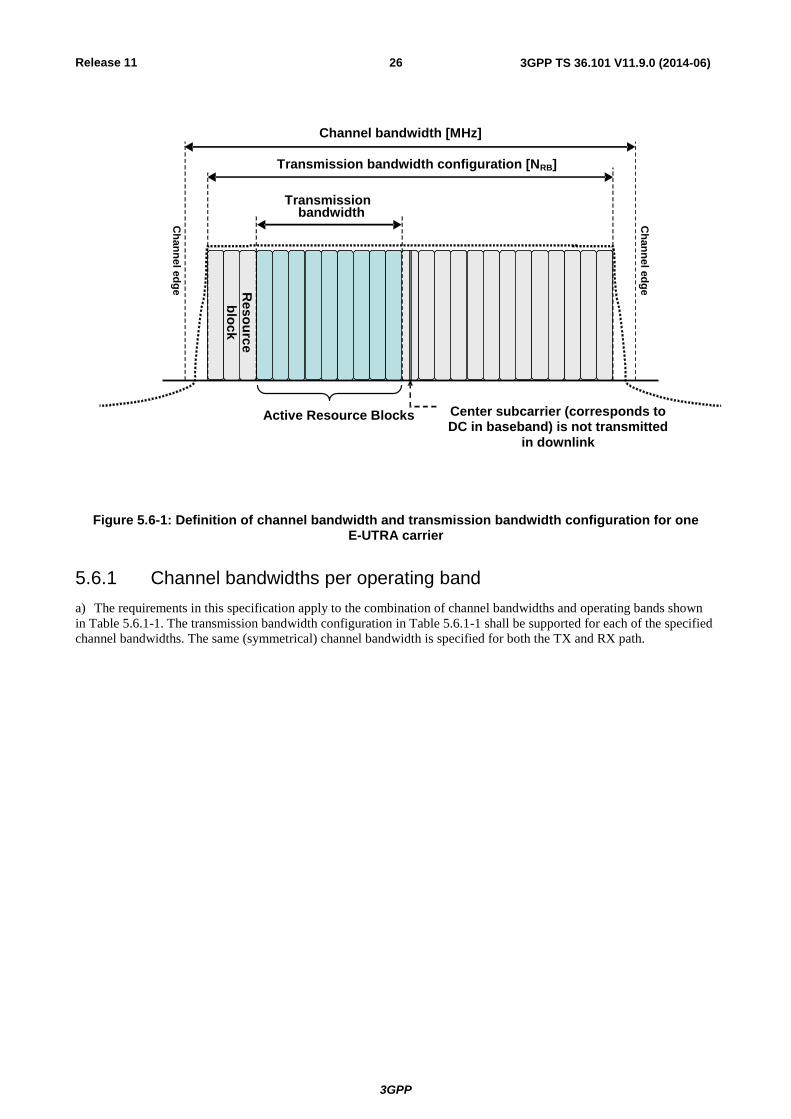
Figure 5.6-1 shows the relation between the Channel bandwidth (BWChannel) and the Transmission bandwidth
configuration (NRB). The channel edges are defined as the lowest and highest frequencies of the carrier separated by the
channel bandwidth, i.e. at FC +/- BWChannel /2.
Release 11
3GPP
3GPP TS 36.101 V11.9.0 (2014-06) 26
Figure 5.6-1: Definition of channel bandwidth and transmission bandwidth configuration for one E-UTRA carrier
5.6.1 Channel bandwidths per operating band
a) The requirements in this specification apply to the combination of channel bandwidths and operating bands shown
in Table 5.6.1-1. The transmission bandwidth configuration in Table 5.6.1-1 shall be supported for each of the specified
channel bandwidths. The same (symmetrical) channel bandwidth is specified for both the TX and RX path.
Transmission
Center subcarrier (corresponds to DC in baseband) is not transmitted
in downlink
Active Resource Blocks
Ch
an
ne
l ed
ge
Ch
an
ne
l ed
ge Reso
urc
e
blo
ck
Transmission bandwidth configuration [NRB]
bandwidth [RB]
Channel bandwidth [MHz]
Release 11
3GPP
3GPP TS 36.101 V11.9.0 (2014-06) 27
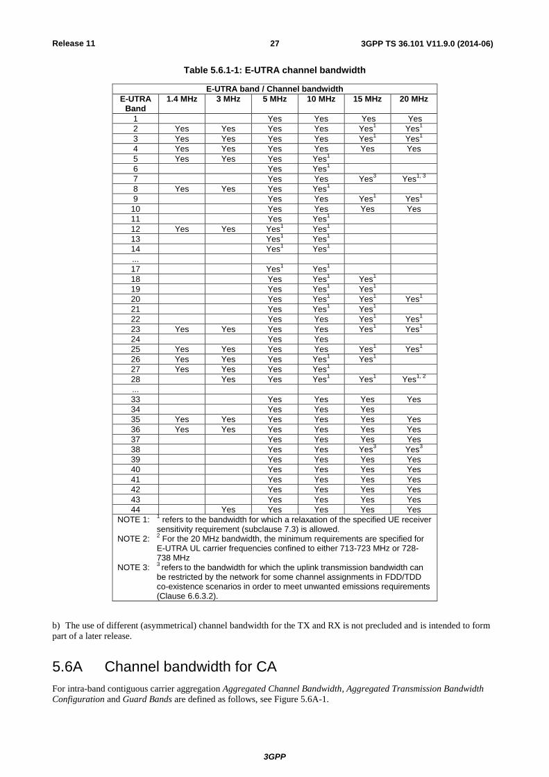
Table 5.6.1-1: E-UTRA channel bandwidth
E-UTRA band / Channel bandwidth
E-UTRA Band
1.4 MHz 3 MHz 5 MHz 10 MHz 15 MHz 20 MHz
1 Yes Yes Yes Yes
2 Yes Yes Yes Yes Yes1 Yes
1
3 Yes Yes Yes Yes Yes1
Yes1
4 Yes Yes Yes Yes Yes Yes
5 Yes Yes Yes Yes1
6 Yes Yes1
7 Yes Yes Yes3 Yes
1, 3
8 Yes Yes Yes Yes1
9 Yes Yes Yes1 Yes
1
10 Yes Yes Yes Yes
11 Yes Yes1
12 Yes Yes Yes1 Yes
1
13 Yes1 Yes
1
14 Yes1 Yes
1
...
17 Yes1 Yes
1
18 Yes Yes1 Yes
1
19 Yes Yes1 Yes
1
20 Yes Yes1 Yes
1 Yes
1
21 Yes Yes1 Yes
1
22 Yes Yes Yes1 Yes
1
23 Yes Yes Yes Yes Yes1 Yes
1
24 Yes Yes
25 Yes Yes Yes Yes Yes1 Yes
1
26 Yes Yes Yes Yes1 Yes
1
27 Yes Yes Yes Yes1
28 Yes Yes Yes1 Yes
1 Yes
1, 2
...
33 Yes Yes Yes Yes
34 Yes Yes Yes
35 Yes Yes Yes Yes Yes Yes
36 Yes Yes Yes Yes Yes Yes
37 Yes Yes Yes Yes
38 Yes Yes Yes3 Yes
3
39 Yes Yes Yes Yes
40 Yes Yes Yes Yes
41 Yes Yes Yes Yes
42 Yes Yes Yes Yes
43 Yes Yes Yes Yes
44 Yes Yes Yes Yes Yes
NOTE 1: 1 refers to the bandwidth for which a relaxation of the specified UE receiver
sensitivity requirement (subclause 7.3) is allowed. NOTE 2:
2 For the 20 MHz bandwidth, the minimum requirements are specified for
E-UTRA UL carrier frequencies confined to either 713-723 MHz or 728-738 MHz
NOTE 3: 3
refers to the bandwidth for which the uplink transmission bandwidth can
be restricted by the network for some channel assignments in FDD/TDD co-existence scenarios in order to meet unwanted emissions requirements (Clause 6.6.3.2).
b) The use of different (asymmetrical) channel bandwidth for the TX and RX is not precluded and is intended to form
part of a later release.
5.6A Channel bandwidth for CA
For intra-band contiguous carrier aggregation Aggregated Channel Bandwidth, Aggregated Transmission Bandwidth
Configuration and Guard Bands are defined as follows, see Figure 5.6A-1.
Release 11
3GPP
3GPP TS 36.101 V11.9.0 (2014-06) 28
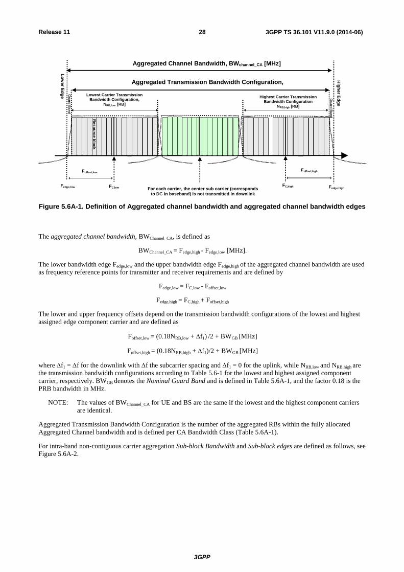
Figure 5.6A-1. Definition of Aggregated channel bandwidth and aggregated channel bandwidth edges
The aggregated channel bandwidth, BWChannel_CA, is defined as
BWChannel_CA = Fedge,high - Fedge,low [MHz].
The lower bandwidth edge Fedge,low and the upper bandwidth edge Fedge,high of the aggregated channel bandwidth are used
as frequency reference points for transmitter and receiver requirements and are defined by
Fedge,low = FC,low - Foffset,low
Fedge,high = FC,high + Foffset,high
The lower and upper frequency offsets depend on the transmission bandwidth configurations of the lowest and highest
assigned edge component carrier and are defined as
Foffset,low = (0.18NRB,low + f1) /2 + BWGB [MHz]
Foffset,high = (0.18NRB,high + f1)/2 + BWGB [MHz]
where f1 = f for the downlink with f the subcarrier spacing and f1 = 0 for the uplink, while NRB,low and NRB,high are
the transmission bandwidth configurations according to Table 5.6-1 for the lowest and highest assigned component
carrier, respectively. BWGB denotes the Nominal Guard Band and is defined in Table 5.6A-1, and the factor 0.18 is the
PRB bandwidth in MHz.
NOTE: The values of BWChannel_CA for UE and BS are the same if the lowest and the highest component carriers
are identical.
Aggregated Transmission Bandwidth Configuration is the number of the aggregated RBs within the fully allocated
Aggregated Channel bandwidth and is defined per CA Bandwidth Class (Table 5.6A-1).
For intra-band non-contiguous carrier aggregation Sub-block Bandwidth and Sub-block edges are defined as follows, see
Figure 5.6A-2.
FC,low
Lo
we
r Ed
ge
Hig
he
r Ed
ge
Lowest Carrier Transmission Bandwidth Configuration,
NRB,low [RB]
FC,high
Foffset,low
Highest Carrier Transmission Bandwidth Configuration
NRB,high [RB]
Res
ou
rce
blo
ck
Aggregated Channel Bandwidth, BWchannel_CA [MHz]
Fedge,low Fedge,high For each carrier, the center sub carrier (corresponds to DC in baseband) is not transmitted in downlink
Foffset,high
Gu
ard
Ban
d
Gu
ard
Ban
d
Aggregated Transmission Bandwidth Configuration, NRB_agg [RB]

Release 11
3GPP
3GPP TS 36.101 V11.9.0 (2014-06) 29
Figure 5.6A-2. Non-contiguous intraband CA terms and definitions
The lower sub-block edge of the Sub-block Bandwidth (BWChannel,block) is defined as
Fedge,block, low = FC,block,low - Foffset,block, low.
The upper sub-block edge of the Sub-block Bandwidth is defined as
Fedge,block,high = FC,block,high + Foffset,block,high .
The Sub-block Bandwidth, BWChannel,block, is defined as follows:
BWChannel,block = Fedge,block,high - Fedge,block,low [MHz]
The lower and upper frequency offsets Foffset,block,low and Foffset,block,high depend on the transmission bandwidth
configurations of the lowest and highest assigned edge component carriers within a sub-block and are defined as
Foffset,block,low = (0.18NRB,low + f1)/2 + BWGB [MHz]
Foffset,block,high = (0.18NRB,high+ f1)/2 + BWGB [MHz]
where f1 = f for the downlink with f the subcarrier spacing and f1 = 0 for the uplink, while NRB,low and NRB,high are
the transmission bandwidth configurations according to Table 5.6-1 for the lowest and highest assigned component
carrier within a sub-block, respectively. BWGB denotes the Nominal Guard Band and is defined in Table 5.6A-1, and the
factor 0.18 is the PRB bandwidth in MHz.
The sub-block gap size between two consecutive sub-blocks Wgap is defined as
Wgap = Fedge,block n+1,low - Fedge,block n,high [MHz]

Release 11
3GPP
3GPP TS 36.101 V11.9.0 (2014-06) 30
Table 5.6A-1: CA bandwidth classes and corresponding nominal guard bands
CA Bandwidth Class
Aggregated Transmission
Bandwidth Configuration
Maximum number of CC
Nominal Guard Band BWGB
A NRB,agg ≤ 100 1 a1BWChannel(1) - 0.5f1 (NOTE 2)
B NRB,agg ≤ 100 2 FFS
C 100 < NRB,agg ≤ 200 2 0.05 max(BWChannel(1),BWChannel(2)) - 0.5f1
D 200 < NRB,agg ≤ [300] FFS FFS
E [300] < NRB,agg ≤ [400] FFS FFS
F [400] < NRB,agg ≤ [500] FFS FFS
NOTE 1: BWChannel(1) and BWChannel(2) are channel bandwidths of two E-UTRA component carriers
according to Table 5.6-1 and f1 = f for the downlink with f the subcarrier spacing while f1 = 0 for the uplink.
NOTE 2: a1 = 0.16/1.4 for BWChannel(1) = 1.4 MHz whereas a1 = 0.05 for all other channel bandwidths.
The channel spacing between centre frequencies of contiguously aggregated component carriers is defined in subclause
5.7.1A.
5.6A.1 Channel bandwidths per operating band for CA
The requirements for carrier aggregation in this specification are defined for carrier aggregation configurations with
associated bandwidth combination sets. For inter-band carrier aggregation, a carrier aggregation configuration is a
combination of operating bands, each supporting a carrier aggregation bandwidth class. For intra-band contiguous
carrier aggregation, a carrier aggregation configuration is a single operating band supporting a carrier aggregation
bandwidth class.
For each carrier aggregation configuration, requirements are specified for all bandwidth combinations contained in a
bandwidth combination set, which is indicated per supported band combination in the UE radio access capability. A UE
can indicate support of several bandwidth combination sets per band combination. Furthermore, if the UE indicates
support of a bandwidth combination set that is a superset of another applicable bandwidth combination set, the latter is
supported by the UE even if not indicated.
Requirements for intra-band contiguous carrier aggregation are defined for the carrier aggregation configurations and
bandwidth combination sets specified in Table 5.6A.1-1. Requirements for inter-band carrier aggregation are defined
for the carrier aggregation configurations and bandwidth combination sets specified in Table 5.6A.1-2.
The DL component carrier combinations for a given CA configuration shall be symmetrical in relation to channel centre
unless stated otherwise in Table 5.6A.1-1 or 5.6A.1-2.
Release 11
3GPP
3GPP TS 36.101 V11.9.0 (2014-06) 31
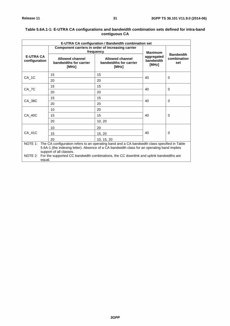
Table 5.6A.1-1: E-UTRA CA configurations and bandwidth combination sets defined for intra-band contiguous CA
E-UTRA CA configuration / Bandwidth combination set
E-UTRA CA configuration
Component carriers in order of increasing carrier frequency Maximum
aggregated bandwidth
[MHz]
Bandwidth combination
set Allowed channel
bandwidths for carrier [MHz]
Allowed channel bandwidths for carrier
[MHz]
CA_1C 15 15
40 0 20 20
CA_7C 15 15
40 0 20 20
CA_38C 15 15
40 0 20 20
CA_40C
10 20
40 0 15 15
20 10, 20
CA_41C
10 20
40 0 15 15, 20
20 10, 15, 20
NOTE 1: The CA configuration refers to an operating band and a CA bandwidth class specified in Table 5.6A-1 (the indexing letter). Absence of a CA bandwidth class for an operating band implies support of all classes.
NOTE 2: For the supported CC bandwidth combinations, the CC downlink and uplink bandwidths are equal.
Release 11
3GPP
3GPP TS 36.101 V11.9.0 (2014-06) 32
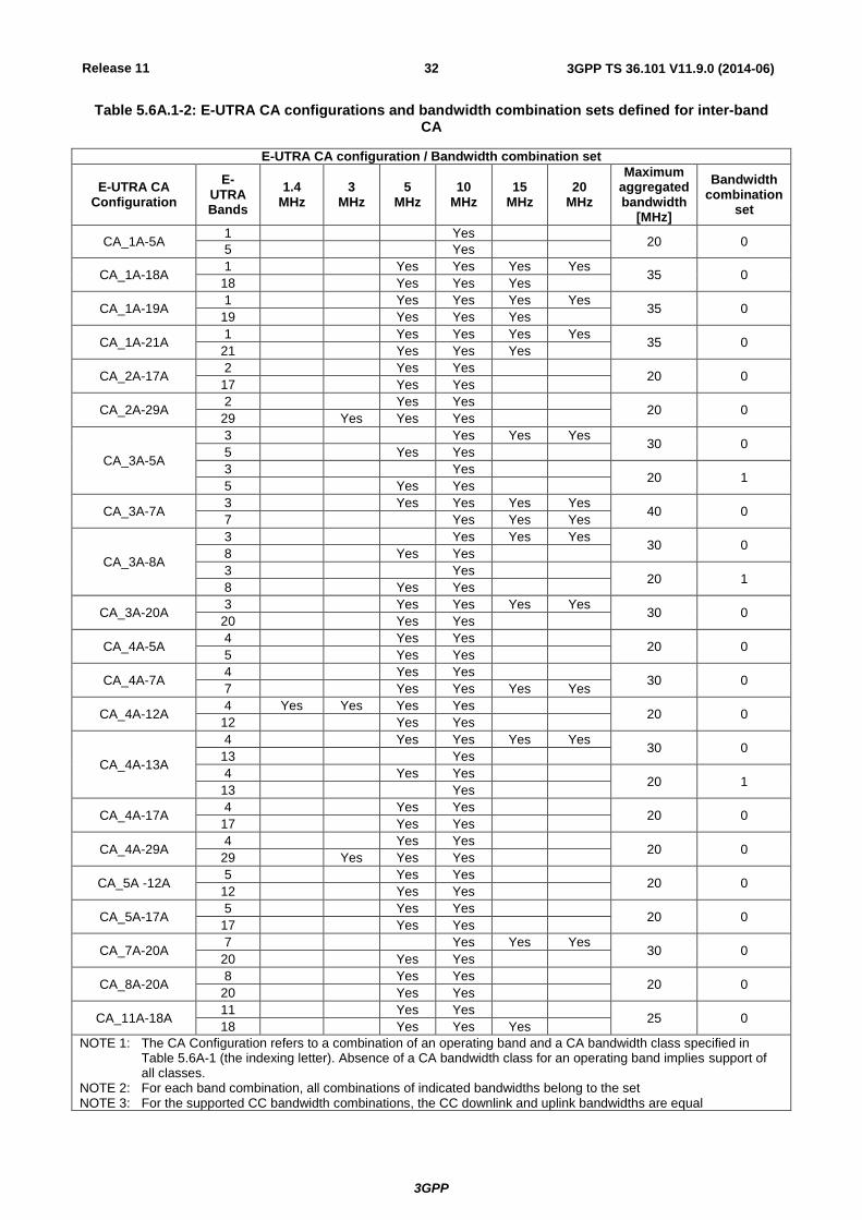
Table 5.6A.1-2: E-UTRA CA configurations and bandwidth combination sets defined for inter-band CA
E-UTRA CA configuration / Bandwidth combination set
E-UTRA CA Configuration
E-UTRA Bands
1.4 MHz
3 MHz
5 MHz
10 MHz
15 MHz
20 MHz
Maximum aggregated bandwidth
[MHz]
Bandwidth combination
set
CA_1A-5A 1 Yes
20 0 5 Yes
CA_1A-18A 1 Yes Yes Yes Yes
35 0 18 Yes Yes Yes
CA_1A-19A 1 Yes Yes Yes Yes
35 0 19 Yes Yes Yes
CA_1A-21A 1 Yes Yes Yes Yes
35 0 21 Yes Yes Yes
CA_2A-17A 2 Yes Yes
20 0 17 Yes Yes
CA_2A-29A 2 Yes Yes
20 0 29 Yes Yes Yes
CA_3A-5A
3 Yes Yes Yes 30 0
5 Yes Yes
3 Yes 20 1
5 Yes Yes
CA_3A-7A 3 Yes Yes Yes Yes
40 0 7 Yes Yes Yes
CA_3A-8A
3 Yes Yes Yes 30 0
8 Yes Yes
3 Yes 20 1
8 Yes Yes
CA_3A-20A 3 Yes Yes Yes Yes
30 0 20 Yes Yes
CA_4A-5A 4 Yes Yes
20 0 5 Yes Yes
CA_4A-7A 4 Yes Yes
30 0 7 Yes Yes Yes Yes
CA_4A-12A 4 Yes Yes Yes Yes
20 0 12 Yes Yes
CA_4A-13A
4 Yes Yes Yes Yes 30 0
13 Yes
4 Yes Yes 20 1
13 Yes
CA_4A-17A 4 Yes Yes
20 0 17 Yes Yes
CA_4A-29A 4 Yes Yes
20 0 29 Yes Yes Yes
CA_5A -12A 5 Yes Yes
20 0 12 Yes Yes
CA_5A-17A 5 Yes Yes
20 0 17 Yes Yes
CA_7A-20A 7 Yes Yes Yes
30 0 20 Yes Yes
CA_8A-20A 8 Yes Yes
20 0 20 Yes Yes
CA_11A-18A 11 Yes Yes
25 0 18 Yes Yes Yes
NOTE 1: The CA Configuration refers to a combination of an operating band and a CA bandwidth class specified in Table 5.6A-1 (the indexing letter). Absence of a CA bandwidth class for an operating band implies support of all classes.
NOTE 2: For each band combination, all combinations of indicated bandwidths belong to the set NOTE 3: For the supported CC bandwidth combinations, the CC downlink and uplink bandwidths are equal

Release 11
3GPP
3GPP TS 36.101 V11.9.0 (2014-06) 33
Table 5.6A.1-3: E-UTRA CA configurations and bandwidth combination sets defined for non-contiguous intra-band CA
E-UTRA CA configuration / Bandwidth combination set
E-UTRA CA configuration
Component carriers in order of increasing carrier frequency
Maximum aggregated bandwidth
[MHz]
Bandwidth combination
set Allowed channel
bandwidths for carrier [MHz]
Allowed channel bandwidths for carrier
[MHz]
CA_25A-25A 5, 10 5, 10 20 0
CA_41A-41A 10, 15, 20 10, 15, 20 40 0
5.6B Channel bandwidth for UL-MIMO
The requirements specified in subclause 5.6 are applicable to UE supporting UL-MIMO.
5.6B.1 Void
5.7 Channel arrangement
5.7.1 Channel spacing
The spacing between carriers will depend on the deployment scenario, the size of the frequency block available and the
channel bandwidths. The nominal channel spacing between two adjacent E-UTRA carriers is defined as following:
Nominal Channel spacing = (BWChannel(1) + BWChannel(2))/2
where BWChannel(1) and BWChannel(2) are the channel bandwidths of the two respective E-UTRA carriers. The channel
spacing can be adjusted to optimize performance in a particular deployment scenario.
5.7.1A Channel spacing for CA
For intra-band contiguous carrier aggregation bandwidth class C, the nominal channel spacing between two adjacent E-
UTRA component carriers is defined as the following:
MHz3.06.0
1.0 spacingchannelNominal
)2()1()2()1(
ChannelChannelChannelChannel BWBWBWBW
where BWChannel(1) and BWChannel(2) are the channel bandwidths of the two respective E-UTRA component carriers
according to Table 5.6-1 with values in MHz. The channel spacing for intra-band contiguous carrier aggregation can be
adjusted to any multiple of 300 kHz less than the nominal channel spacing to optimize performance in a particular
deployment scenario.
For intra-band non-contiguous carrier aggregation the channel spacing between two E-UTRA component carriers in
different sub-blocks shall be larger than the nominal channel spacing defined in this subclause.
5.7.2 Channel raster
The channel raster is 100 kHz for all bands, which means that the carrier centre frequency must be an integer multiple
of 100 kHz.
Release 11
3GPP
3GPP TS 36.101 V11.9.0 (2014-06) 34
5.7.2A Channel raster for CA
For carrier aggregation the channel raster is 100 kHz for all bands, which means that the carrier centre frequency must
be an integer multiple of 100 kHz.
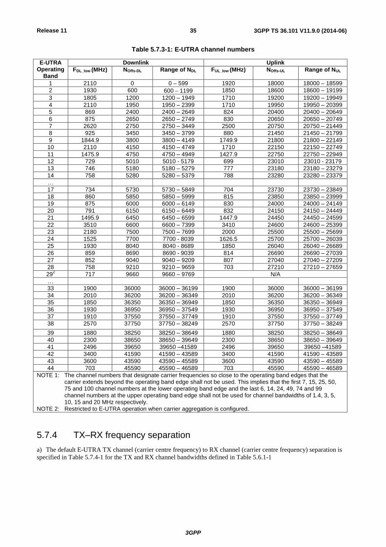
5.7.3 Carrier frequency and EARFCN
The carrier frequency in the uplink and downlink is designated by the E-UTRA Absolute Radio Frequency Channel
Number (EARFCN) in the range 0 - 65535. The relation between EARFCN and the carrier frequency in MHz for the
downlink is given by the following equation, where FDL_low and NOffs-DL are given in Table 5.7.3-1 and NDL is the
downlink EARFCN.
FDL = FDL_low + 0.1(NDL – NOffs-DL)
The relation between EARFCN and the carrier frequency in MHz for the uplink is given by the following equation
where FUL_low and NOffs-UL are given in Table 5.7.3-1 and NUL is the uplink EARFCN.
FUL = FUL_low + 0.1(NUL – NOffs-UL)
Release 11
3GPP
3GPP TS 36.101 V11.9.0 (2014-06) 35
Table 5.7.3-1: E-UTRA channel numbers
E-UTRA Operating
Band
Downlink Uplink
FDL_low (MHz) NOffs-DL Range of NDL FUL_low (MHz) NOffs-UL Range of NUL
1 2110 0 0 – 599 1920 18000 18000 – 18599
2 1930 600 6001199 1850 18600 18600 – 19199
3 1805 1200 1200 – 1949 1710 19200 19200 – 19949
4 2110 1950 1950 – 2399 1710 19950 19950 – 20399
5 869 2400 2400 – 2649 824 20400 20400 – 20649
6 875 2650 2650 – 2749 830 20650 20650 – 20749
7 2620 2750 2750 – 3449 2500 20750 20750 – 21449
8 925 3450 3450 – 3799 880 21450 21450 – 21799
9 1844.9 3800 3800 – 4149 1749.9 21800 21800 – 22149
10 2110 4150 4150 – 4749 1710 22150 22150 – 22749
11 1475.9 4750 4750 – 4949 1427.9 22750 22750 – 22949
12 729 5010 5010 - 5179 699 23010 23010 - 23179
13 746 5180 5180 – 5279 777 23180 23180 – 23279
14 758 5280 5280 – 5379 788 23280 23280 – 23379
…
17 734 5730 5730 – 5849 704 23730 23730 – 23849
18 860 5850 5850 – 5999 815 23850 23850 – 23999
19 875 6000 6000 – 6149 830 24000 24000 – 24149
20 791 6150 6150 – 6449 832 24150 24150 – 24449
21 1495.9 6450 6450 – 6599 1447.9 24450 24450 – 24599
22 3510 6600 6600 – 7399 3410 24600 24600 – 25399
23 2180 7500 7500 – 7699 2000 25500 25500 – 25699
24 1525 7700 7700 - 8039 1626.5 25700 25700 – 26039
25 1930 8040 8040 - 8689 1850 26040 26040 – 26689
26 859 8690 8690 - 9039 814 26690 26690 – 27039
27 852 9040 9040 – 9209 807 27040 27040 – 27209
28 758 9210 9210 – 9659 703 27210 27210 – 27659
292 717 9660 9660 – 9769 N/A
…
33 1900 36000 36000 – 36199 1900 36000 36000 – 36199
34 2010 36200 36200 – 36349 2010 36200 36200 – 36349
35 1850 36350 36350 – 36949 1850 36350 36350 – 36949
36 1930 36950 36950 – 37549 1930 36950 36950 – 37549
37 1910 37550 37550 – 37749 1910 37550 37550 – 37749
38 2570 37750 37750 – 38249 2570 37750 37750 – 38249
39 1880 38250 38250 – 38649 1880 38250 38250 – 38649
40 2300 38650 38650 – 39649 2300 38650 38650 – 39649
41 2496 39650 39650 –41589 2496 39650 39650 –41589
42 3400 41590 41590 – 43589 3400 41590 41590 – 43589
43 3600 43590 43590 – 45589 3600 43590 43590 – 45589
44 703 45590 45590 – 46589 703 45590 45590 – 46589
NOTE 1: The channel numbers that designate carrier frequencies so close to the operating band edges that the carrier extends beyond the operating band edge shall not be used. This implies that the first 7, 15, 25, 50, 75 and 100 channel numbers at the lower operating band edge and the last 6, 14, 24, 49, 74 and 99 channel numbers at the upper operating band edge shall not be used for channel bandwidths of 1.4, 3, 5, 10, 15 and 20 MHz respectively.
NOTE 2: Restricted to E-UTRA operation when carrier aggregation is configured.
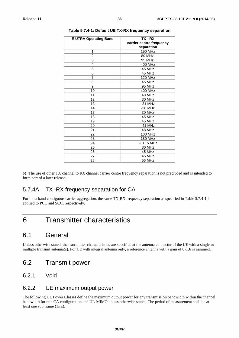
5.7.4 TX–RX frequency separation
a) The default E-UTRA TX channel (carrier centre frequency) to RX channel (carrier centre frequency) separation is
specified in Table 5.7.4-1 for the TX and RX channel bandwidths defined in Table 5.6.1-1
Release 11
3GPP
3GPP TS 36.101 V11.9.0 (2014-06) 36
Table 5.7.4-1: Default UE TX-RX frequency separation
E-UTRA Operating Band TX - RX carrier centre frequency
separation
1 190 MHz
2 80 MHz.
3 95 MHz.
4 400 MHz
5 45 MHz
6 45 MHz
7 120 MHz
8 45 MHz
9 95 MHz
10 400 MHz
11 48 MHz
12 30 MHz
13 -31 MHz
14 -30 MHz
17 30 MHz
18 45 MHz
19 45 MHz
20 -41 MHz
21 48 MHz
22 100 MHz
23 180 MHz
24 -101.5 MHz
25 80 MHz
26 45 MHz
27 45 MHz
28 55 MHz
b) The use of other TX channel to RX channel carrier centre frequency separation is not precluded and is intended to
form part of a later release.
5.7.4A TX–RX frequency separation for CA
For intra-band contiguous carrier aggregation, the same TX-RX frequency separation as specified in Table 5.7.4-1 is
applied to PCC and SCC, respectively.
6 Transmitter characteristics
6.1 General
Unless otherwise stated, the transmitter characteristics are specified at the antenna connector of the UE with a single or
multiple transmit antenna(s). For UE with integral antenna only, a reference antenna with a gain of 0 dBi is assumed.
6.2 Transmit power
6.2.1 Void
6.2.2 UE maximum output power
The following UE Power Classes define the maximum output power for any transmission bandwidth within the channel
bandwidth for non CA configuration and UL-MIMO unless otherwise stated. The period of measurement shall be at
least one sub frame (1ms).

Release 11
3GPP
3GPP TS 36.101 V11.9.0 (2014-06) 37
Table 6.2.2-1: UE Power Class
EUTRA band
Class 1 (dBm)
Tolerance (dB)
Class 2 (dBm)
Tolerance (dB)
Class 3 (dBm)
Tolerance (dB)
Class 4 (dBm)
Tolerance (dB)
1 23 ±2
2 23 ±22
3 23 ±22
4 23 ±2
5 23 ±2
6 23 ±2
7 23 ±22
8 23 ±22
9 23 ±2
10 23 ±2
11 23 ±2
12 23 ±22
13 23 ±2
14 31 +2/-3 23 ±2
17 23 ±2
18 23 ±25
19 23 ±2
20 23 ±22
21 23 ±2
22 23 +2/-3.52
23 236 ±2
6
24 23 ±2
25 23 ±22
26 23 ±22
27 23 ±2
28 23 +2/-2.5
…
33 23 ±2
34 23 ±2
35 23 ±2
36 23 ±2
37 23 ±2
38 23 ±2
39 23 ±2
40 23 ±2
41 23 ±22
42 23 +2/-3
43 23 +2/-3
44 23 +2/[-3]
NOTE 1: Void NOTE 2:
2 refers to the transmission bandwidths (Figure 5.6-1) confined within FUL_low and FUL_low + 4 MHz or
FUL_high – 4 MHz and FUL_high, the maximum output power requirement is relaxed by reducing the lower tolerance limit by 1.5 dB
NOTE 3: For the UE which supports both Band 11 and Band 21 operating frequencies, the tolerance is FFS. NOTE 4: PPowerClass is the maximum UE power specified without taking into account the tolerance NOTE 5: For a UE that supports both Band 18 and Band 26, the maximum output power requirement is relaxed by
reducing the lower tolerance limit by 1.5 dB for transmission bandwidths confined within 815 MHz and 818 MHz.
NOTE 6: When NS_20 is signalled, the total output power within 2000-2005 MHz shall be limited to 7 dBm.
6.2.2A UE maximum output power for CA
The following UE Power Classes define the maximum output power for any transmission bandwidth within the
aggregated channel bandwidth.
The maximum output power is measured as the sum of the maximum output power at each UE antenna connector. The
period of measurement shall be at least one sub frame (1ms).
For inter-band carrier aggregation with uplink assigned to one E-UTRA band the requirements in subclause 6.2.2 apply.
Release 11
3GPP
3GPP TS 36.101 V11.9.0 (2014-06) 38
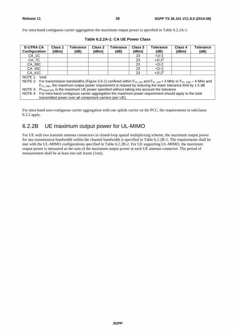
For intra-band contiguous carrier aggregation the maximum output power is specified in Table 6.2.2A-1.
Table 6.2.2A-1: CA UE Power Class
E-UTRA CA Configuration
Class 1 (dBm)
Tolerance (dB)
Class 2 (dBm)
Tolerance (dB)
Class 3 (dBm)
Tolerance (dB)
Class 4 (dBm)
Tolerance (dB)
CA_1C 23 +2/-2
CA_7C 23 +2/-22
CA_38C 23 +2/-2
CA_40C 23 +2/-2
CA_41C 23 +2/-22
NOTE 1: Void NOTE 2: For transmission bandwidths (Figure 5.6-1) confined within FUL_low and FUL_low + 4 MHz or FUL_high – 4 MHz and
FUL_high, the maximum output power requirement is relaxed by reducing the lower tolerance limit by 1.5 dB NOTE 3: PPowerClass is the maximum UE power specified without taking into account the tolerance NOTE 4: For intra-band contiguous carrier aggregation the maximum power requirement should apply to the total
transmitted power over all component carriers (per UE).
For intra-band non-contiguous carrier aggregation with one uplink carrier on the PCC, the requirements in subclause
6.2.2 apply.
6.2.2B UE maximum output power for UL-MIMO
For UE with two transmit antenna connectors in closed-loop spatial multiplexing scheme, the maximum output power
for any transmission bandwidth within the channel bandwidth is specified in Table 6.2.2B-1. The requirements shall be
met with the UL-MIMO configurations specified in Table 6.2.2B-2. For UE supporting UL-MIMO, the maximum
output power is measured as the sum of the maximum output power at each UE antenna connector. The period of
measurement shall be at least one sub frame (1ms).

Release 11
3GPP
3GPP TS 36.101 V11.9.0 (2014-06) 39
Table 6.2.2B-1: UE Power Class for UL-MIMO in closed loop spatial multiplexing scheme
EUTRA band
Class 1 (dBm)
Tolerance (dB)
Class 2 (dBm)
Tolerance (dB)
Class 3 (dBm)
Tolerance (dB)
Class 4 (dBm)
Tolerance (dB)
1 23 +2/-3
2 23 +2/-32
3 23 +2/-32
4 23 +2/-3
5 23 +2/-3
6 23 +2/-3
7 23 +2/-32
8 23 +2/-32
9 23 +2/-3
10 23 +2/-3
11 23 +2/-3
12 23 +2/-32
13 23 +2/-3
14 23 +2/-3
17 23 +2/-3
18 23 +2/-3
19 23 +2/-3
20 23 +2/-32
21 23 +2/-3
22 +2/-4.52
…
23 23 +2/-3
24 23 +2/-3
25 23 +2/-32
26 23 +2/-32
27 23 +2/-3
28 23 +2/[-3]
…
33 23 +2/-3
34 23 +2/-3
35 23 +2/-3
36 23 +2/-3
37 23 +2/-3
38 23 +2/-3
39 23 +2/-3
40 23 +2/-3
41 23 +2/-32
42 23 +2/-4
43 23 +2/-4
44 23 +2/[-3]
NOTE 1: Void NOTE 2:
2 refers to the transmission bandwidths (Figure 5.6-1) confined within FUL_low and FUL_low + 4 MHz or
FUL_high – 4 MHz and FUL_high, the maximum output power requirement is relaxed by reducing the lower tolerance limit by 1.5 dB
NOTE 3: For the UE which supports both Band 11 and Band 21 operating frequencies, the tolerance is FFS. NOTE 4: PPowerClass is the maximum UE power specified without taking into account the tolerance
Table 6.2.2B-2: UL-MIMO configuration in closed-loop spatial multiplexing scheme
Transmission mode DCI format Codebook Index
Mode 2 DCI format 4 Codebook index 0
For single-antenna port scheme, the requirements in subclause 6.2.2 apply.

Release 11
3GPP
3GPP TS 36.101 V11.9.0 (2014-06) 40
6.2.3 UE maximum output power for modulation / channel bandwidth
For UE Power Class 1 and 3, the allowed Maximum Power Reduction (MPR) for the maximum output power in Table
6.2.2-1due to higher order modulation and transmit bandwidth configuration (resource blocks) is specified in Table
6.2.3-1.
Table 6.2.3-1: Maximum Power Reduction (MPR) for Power Class 1 and 3
Modulation Channel bandwidth / Transmission bandwidth (NRB) MPR (dB)
1.4 MHz
3.0 MHz
5 MHz
10 MHz
15 MHz
20 MHz
QPSK > 5 > 4 > 8 > 12 > 16 > 18 ≤ 1
16 QAM ≤ 5 ≤ 4 ≤ 8 ≤ 12 ≤ 16 ≤ 18 ≤ 1
16 QAM > 5 > 4 > 8 > 12 > 16 > 18 ≤ 2
For PRACH, PUCCH and SRS transmissions, the allowed MPR is according to that specified for PUSCH QPSK
modulation for the corresponding transmission bandwidth.
For each subframe, the MPR is evaluated per slot and given by the maximum value taken over the transmission(s)
within the slot; the maximum MPR over the two slots is then applied for the entire subframe.
For transmissions with non-contiguous resource allocation in single component carrier, the allowed Maximum Power
Reduction (MPR) for the maximum output power in table 6.2.2-1, is specified as follows
MPR = CEIL {MA, 0.5}
Where MA is defined as follows
MA = [8.0]-[10.12]A ; 0< A ≤ [0.33]
[5.67] - [3.07]A ; [0.33]< A ≤[0.77]
[3.31] ; [0.77]< A ≤[1.0]
Where
A = NRB_alloc / NRB.
CEIL{MA, 0.5} means rounding upwards to closest 0.5dB, i.e. MPR [3.0, 3.5 4.0 4.5 5.0 5.5 6.0 6.5 7.0 7.5
8.0]
For the UE maximum output power modified by MPR, the power limits specified in subclause 6.2.5 apply.
6.2.3A UE Maximum Output power for modulation / channel bandwidth for CA
For inter-band carrier aggregation with uplink assigned to one E-UTRA band (Table 5.6A-1), the requirements in
subclause 6.2.3 apply.
For intra-band contiguous carrier aggregation the allowed Maximum Power Reduction (MPR) for the maximum output
power in Table 6.2.2A-1due to higher order modulation and contiguously aggregated transmit bandwidth configuration
(resource blocks) is specified in Table 6.2.3A-1. In case the modulation format is different on different component
carriers then the MPR is determined by the rules applied to higher order of those modulations.
Release 11
3GPP
3GPP TS 36.101 V11.9.0 (2014-06) 41
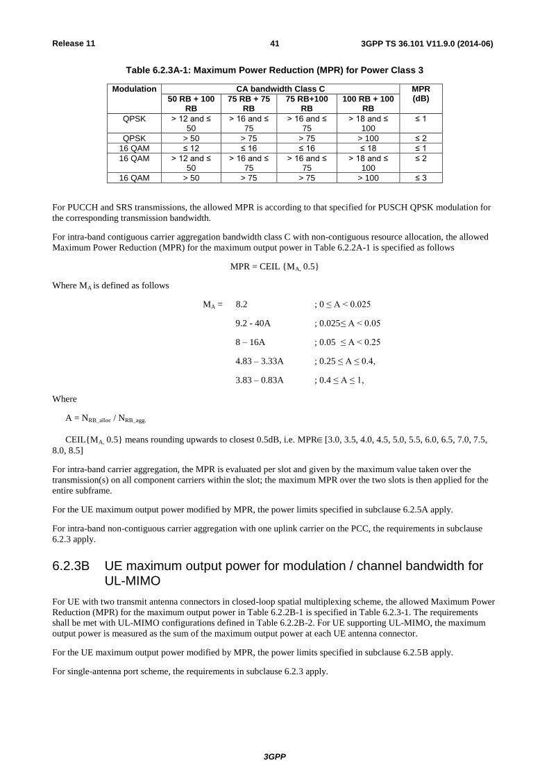
Table 6.2.3A-1: Maximum Power Reduction (MPR) for Power Class 3
Modulation CA bandwidth Class C MPR (dB) 50 RB + 100
RB 75 RB + 75
RB 75 RB+100
RB 100 RB + 100
RB
QPSK > 12 and ≤ 50
> 16 and ≤ 75
> 16 and ≤ 75
> 18 and ≤ 100
≤ 1
QPSK > 50 > 75 > 75 > 100 ≤ 2
16 QAM ≤ 12 ≤ 16 ≤ 16 ≤ 18 ≤ 1
16 QAM > 12 and ≤ 50
> 16 and ≤ 75
> 16 and ≤ 75
> 18 and ≤ 100
≤ 2
16 QAM > 50 > 75 > 75 > 100 ≤ 3
For PUCCH and SRS transmissions, the allowed MPR is according to that specified for PUSCH QPSK modulation for
the corresponding transmission bandwidth.
For intra-band contiguous carrier aggregation bandwidth class C with non-contiguous resource allocation, the allowed
Maximum Power Reduction (MPR) for the maximum output power in Table 6.2.2A-1 is specified as follows
MPR = CEIL {MA, 0.5}
Where MA is defined as follows
MA = 8.2 ; 0 ≤ A < 0.025
9.2 - 40A ; 0.025 ≤ A < 0.05
8 – 16A ; 0.05 ≤ A < 0.25
4.83 – 3.33A ; 0.25 ≤ A ≤ 0.4,
3.83 – 0.83A ; 0.4 ≤ A ≤ 1,
Where
A = NRB_alloc / NRB_agg.
CEIL{MA, 0.5} means rounding upwards to closest 0.5dB, i.e. MPR[3.0, 3.5, 4.0, 4.5, 5.0, 5.5, 6.0, 6.5, 7.0, 7.5,
8.0, 8.5]
For intra-band carrier aggregation, the MPR is evaluated per slot and given by the maximum value taken over the
transmission(s) on all component carriers within the slot; the maximum MPR over the two slots is then applied for the
entire subframe.
For the UE maximum output power modified by MPR, the power limits specified in subclause 6.2.5A apply.
For intra-band non-contiguous carrier aggregation with one uplink carrier on the PCC, the requirements in subclause
6.2.3 apply.
6.2.3B UE maximum output power for modulation / channel bandwidth for UL-MIMO
For UE with two transmit antenna connectors in closed-loop spatial multiplexing scheme, the allowed Maximum Power
Reduction (MPR) for the maximum output power in Table 6.2.2B-1 is specified in Table 6.2.3-1. The requirements
shall be met with UL-MIMO configurations defined in Table 6.2.2B-2. For UE supporting UL-MIMO, the maximum
output power is measured as the sum of the maximum output power at each UE antenna connector.
For the UE maximum output power modified by MPR, the power limits specified in subclause 6.2.5B apply.
For single-antenna port scheme, the requirements in subclause 6.2.3 apply.

Release 11
3GPP
3GPP TS 36.101 V11.9.0 (2014-06) 42
6.2.4 UE maximum output power with additional requirements
Additional ACLR and spectrum emission requirements can be signalled by the network to indicate that the UE shall
also meet additional requirements in a specific deployment scenario. To meet these additional requirements, Additional
Maximum Power Reduction (A-MPR) is allowed for the output power as specified in Table 6.2.2-1. Unless stated
otherwise, an A-MPR of 0 dB shall be used.
For UE Power Class 1 and 3 the specific requirements and identified subclauses are specified in Table 6.2.4-1 along
with the allowed A-MPR values that may be used to meet these requirements. The allowed A-MPR values specified
below in Table 6.2.4.-1 to 6.2.4-15 are in addition to the allowed MPR requirements specified in subclause 6.2.3.
Table 6.2.4-1: Additional Maximum Power Reduction (A-MPR)
Network Signalling
value
Requirements (subclause)
E-UTRA Band Channel bandwidth
(MHz)
Resources Blocks (NRB)
A-MPR (dB)
NS_01 6.6.2.1.1 Table 5.5-1 1.4, 3, 5, 10,
15, 20 Table 5.6-1 N/A
NS_03 6.6.2.2.1 2, 4,10, 23, 25,
35, 36
3 >5 ≤ 1
5 >6 ≤ 1
10 >6 ≤ 1
15 >8 ≤ 1
20 >10 ≤ 1
NS_04 6.6.2.2.2 41 5 >6 ≤ 1
10, 15, 20 Table 6.2.4-4
NS_05 6.6.3.3.1 1 10,15,20 ≥ 50 ≤ 1
NS_06 6.6.2.2.3 12, 13, 14, 17 1.4, 3, 5, 10 Table 5.6-1 N/A
NS_07 6.6.2.2.3 6.6.3.3.2
13 10 Table 6.2.4-2
NS_08 6.6.3.3.3 19 10, 15 > 44 ≤ 3
NS_09 6.6.3.3.4 21 10, 15 > 40 ≤ 1
> 55 ≤ 2
NS_10 20 15, 20 Table 6.2.4-3
NS_11 6.6.2.2.1
6.6.3.3.13 23
1.4, 3, 5, 10, 15, 20
Table 6.2.4-5
NS_12 6.6.3.3.5 26 1.4, 3, 5 Table 6.2.4-6
NS_13 6.6.3.3.6 26 5 Table 6.2.4-7
NS_14 6.6.3.3.7 26 10, 15 Table 6.2.4-8
NS_15 6.6.3.3.8 26 1.4, 3, 5, 10,
15 Table 6.2.4-9
Table 6.2.4-10
NS_16 6.6.3.3.9 27 3, 5, 10 Table 6.2.4-11, Table 6.2.4-12,
Table 6.2.4-13
NS_17 6.6.3.3.10 28 5, 10 Table 5.6-1 N/A
NS_18 6.6.3.3.11 28 5 ≥ 2 ≤ 1
10, 15, 20 ≥ 1 ≤ 4
NS_19 6.6.3.3.12 44 10, 15, 20 Table 6.2.4-14
NS_20 6.2.2
6.6.2.2.1 6.6.3.3.14
23 5, 10, 15, 20 Table 6.2.4-15
NS_22 6.6.3.3.15 42 5, 10, 15, 20 Table 5.6-1 [0]
NS_23 6.6.3.3.16 43 5, 10, 15, 20 Table 5.6-1 [0]
...
NS_32 - - - - -
Release 11
3GPP
3GPP TS 36.101 V11.9.0 (2014-06) 43
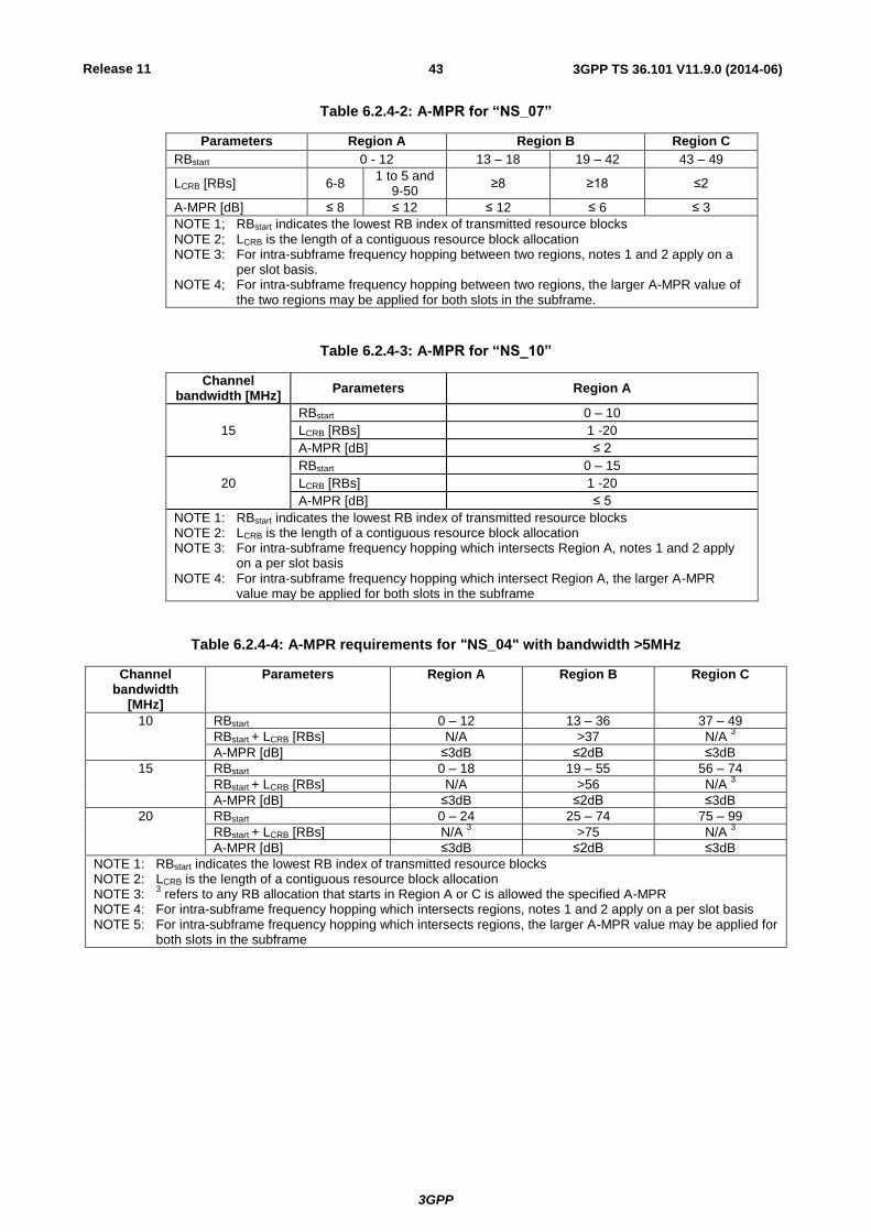
Table 6.2.4-2: A-MPR for “NS_07”
Parameters Region A Region B Region C
RBstart 0 - 12 13 – 18 19 – 42 43 – 49
LCRB [RBs] 6-8 1 to 5 and
9-50 ≥8 ≥18 ≤2
A-MPR [dB] ≤ 8 ≤ 12 ≤ 12 ≤ 6 ≤ 3
NOTE 1; RBstart indicates the lowest RB index of transmitted resource blocks NOTE 2; LCRB is the length of a contiguous resource block allocation NOTE 3: For intra-subframe frequency hopping between two regions, notes 1 and 2 apply on a
per slot basis. NOTE 4; For intra-subframe frequency hopping between two regions, the larger A-MPR value of
the two regions may be applied for both slots in the subframe.
Table 6.2.4-3: A-MPR for “NS_10”
Channel bandwidth [MHz]
Parameters Region A
15
RBstart 0 – 10
LCRB [RBs] 1 -20
A-MPR [dB] ≤ 2
20
RBstart 0 – 15
LCRB [RBs] 1 -20
A-MPR [dB] ≤ 5
NOTE 1: RBstart indicates the lowest RB index of transmitted resource blocks NOTE 2: LCRB is the length of a contiguous resource block allocation NOTE 3: For intra-subframe frequency hopping which intersects Region A, notes 1 and 2 apply
on a per slot basis NOTE 4: For intra-subframe frequency hopping which intersect Region A, the larger A-MPR
value may be applied for both slots in the subframe
Table 6.2.4-4: A-MPR requirements for "NS_04" with bandwidth >5MHz
Channel bandwidth
[MHz]
Parameters Region A Region B Region C
10 RBstart 0 – 12 13 – 36 37 – 49
RBstart + LCRB [RBs] N/A >37 N/A
3
A-MPR [dB] ≤3dB ≤2dB ≤3dB
15 RBstart 0 – 18 19 – 55 56 – 74
RBstart + LCRB [RBs] N/A >56 N/A
3
A-MPR [dB] ≤3dB ≤2dB ≤3dB
20 RBstart 0 – 24 25 – 74 75 – 99
RBstart + LCRB [RBs] N/A
3 >75 N/A
3
A-MPR [dB] ≤3dB ≤2dB ≤3dB
NOTE 1: RBstart indicates the lowest RB index of transmitted resource blocks NOTE 2: LCRB is the length of a contiguous resource block allocation NOTE 3:
3 refers to any RB allocation that starts in Region A or C is allowed the specified A-MPR
NOTE 4: For intra-subframe frequency hopping which intersects regions, notes 1 and 2 apply on a per slot basis NOTE 5: For intra-subframe frequency hopping which intersects regions, the larger A-MPR value may be applied for
both slots in the subframe
Release 11
3GPP
3GPP TS 36.101 V11.9.0 (2014-06) 44
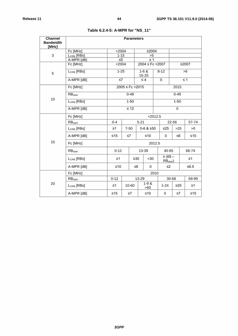
Table 6.2.4-5: A-MPR for "NS_11"
Channel Bandwidth
[MHz]
Parameters
3
Fc [MHz] <2004 ≥2004
LCRB [RBs] 1-15 >5
A-MPR [dB] ≤5 ≤ 1
5
Fc [MHz] <2004 2004 ≤ Fc <2007 ≥2007
LCRB [RBs] 1-25 1-6 & 15-25
8-12 >6
A-MPR [dB] ≤7 ≤ 4 0 ≤ 1
10
Fc [MHz] 2005 ≤ Fc <2015 2015
RBstart 0-49 0-49
LCRB [RBs] 1-50 1-50
A-MPR [dB] ≤ 12 0
15
Fc [MHz] <2012.5
RBstart 0-4 5-21 22-56 57-74
LCRB [RBs] ≥1 7-50 0-6 & ≥50 ≤25 >25 >0
A-MPR [dB] ≤15 ≤7 ≤10 0 ≤6 ≤15
Fc [MHz] 2012.5
RBstart 0-12 13-39 40-65 66-74
LCRB [RBs] ≥1 ≥30 <30 ≥ (69 – RBstart)
≥1
A-MPR [dB] ≤10 ≤6 0 ≤2 ≤6.5
20
Fc [MHz] 2010
RBstart 0-12 13-29 30-68 69-99
LCRB [RBs] ≥1 10-60 1-9 & >60
1-24 ≥25 ≥1
A-MPR [dB] ≤15 ≤7 ≤10 0 ≤7 ≤15

Release 11
3GPP
3GPP TS 36.101 V11.9.0 (2014-06) 45
Table 6.2.4-6: A-MPR for “NS_12”
Channel bandwidth
[MHz] Parameters Region A Region B
1.4
RBstart 0 1-2
LCRB [RBs] ≤3 ≥4 ≥4
A-MPR [dB] ≤3 ≤6 ≤3
3
RBstart 0-3 4-5
LCRB [RBs] 4-9 1-3 and 10-15 ≥9
A-MPR [dB] ≤4 ≤3 ≤3
5
RBstart 0-6 7-9
LCRB [RBs] ≤8 ≥9 ≥15
A-MPR [dB] ≤5 ≤3 ≤3
Table 6.2.4-7: A-MPR for “NS_13”
Channel bandwidth
[MHz] Parameters Region A
5
RBstart 0-2
LCRB [RBs] ≤5 ≥18
A-MPR [dB] ≤3 ≤2
Table 6.2.4-8: A-MPR for “NS_14”
Channel bandwidth
[MHz] Parameters Region A
10
RBstart 0
LCRB [RBs] ≤5 ≥50
A-MPR [dB] ≤3 ≤1
15
RBstart ≤8
LCRB [RBs] ≤16 ≥50
A-MPR [dB] ≤3 ≤1
Table 6.2.4-9: A-MPR for “NS_15” for E-UTRA highest channel edge > 845 MHz and ≤ 849 MHz
Channel bandwidth
[MHz]
Parameters Region A Region B Region C
1.4 RBend [RB] 4-5
A-MPR [dB] ≤3
3
RBend [RB] 0-1 8-12 13-14
LCRB [RB] ≤2 ≥8 >0
A-MPR [dB] ≤4 ≤4 ≤9
5
RBend [RB] 0-4 12-19 20-24
LCRB [RB] ≤2 ≥8 >0
A-MPR [dB] ≤4 ≤5 ≤9
10
RBend [RB] 0-12 23-36 37-49
LCRB [RB] ≤2 ≥15 >0
A-MPR [dB] ≤4 ≤6 ≤9
15
RBend [RB] 0-20 26-53 54-74
LCRB [RB] ≤2 ≥20 >0
A-MPR [dB] ≤4 ≤5 ≤9
Release 11
3GPP
3GPP TS 36.101 V11.9.0 (2014-06) 46
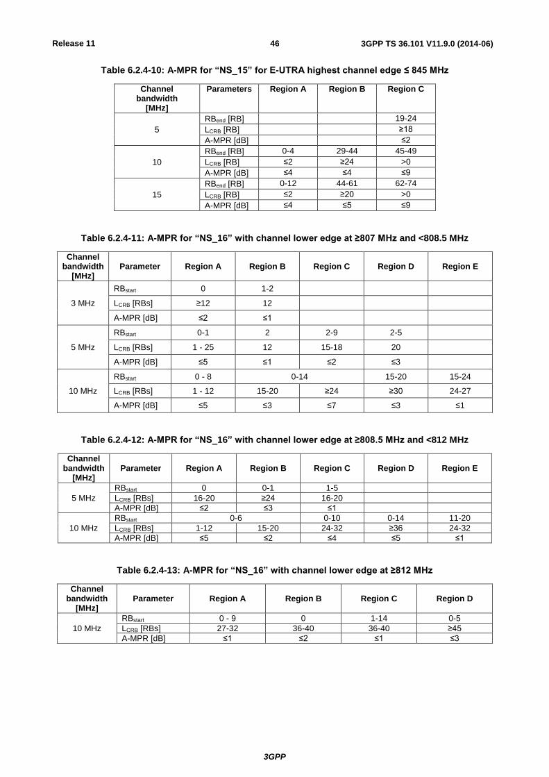
Table 6.2.4-10: A-MPR for “NS_15” for E-UTRA highest channel edge ≤ 845 MHz
Channel bandwidth
[MHz]
Parameters Region A Region B Region C
5
RBend [RB] 19-24
LCRB [RB] ≥18
A-MPR [dB] ≤2
10
RBend [RB] 0-4 29-44 45-49
LCRB [RB] ≤2 ≥24 >0
A-MPR [dB] ≤4 ≤4 ≤9
15
RBend [RB] 0-12 44-61 62-74
LCRB [RB] ≤2 ≥20 >0
A-MPR [dB] ≤4 ≤5 ≤9
Table 6.2.4-11: A-MPR for “NS_16” with channel lower edge at ≥807 MHz and <808.5 MHz
Channel bandwidth
[MHz] Parameter Region A Region B Region C Region D Region E
3 MHz
RBstart 0 1-2
LCRB [RBs] ≥12 12
A-MPR [dB] ≤2 ≤1
5 MHz
RBstart 0-1 2 2-9 2-5
LCRB [RBs] 1 - 25 12 15-18 20
A-MPR [dB] ≤5 ≤1 ≤2 ≤3
10 MHz
RBstart 0 - 8 0-14 15-20 15-24
LCRB [RBs] 1 - 12 15-20 ≥24 ≥30 24-27
A-MPR [dB] ≤5 ≤3 ≤7 ≤3 ≤1
Table 6.2.4-12: A-MPR for “NS_16” with channel lower edge at ≥808.5 MHz and <812 MHz
Channel bandwidth
[MHz] Parameter Region A Region B Region C Region D Region E
5 MHz
RBstart 0 0-1 1-5
LCRB [RBs] 16-20 ≥24 16-20
A-MPR [dB] ≤2 ≤3 ≤1
10 MHz
RBstart 0-6 0-10 0-14 11-20
LCRB [RBs] 1-12 15-20 24-32 ≥36 24-32
A-MPR [dB] ≤5 ≤2 ≤4 ≤5 ≤1
Table 6.2.4-13: A-MPR for “NS_16” with channel lower edge at ≥812 MHz
Channel bandwidth
[MHz] Parameter Region A Region B Region C Region D
10 MHz
RBstart 0 - 9 0 1-14 0-5
LCRB [RBs] 27-32 36-40 36-40 ≥45
A-MPR [dB] ≤1 ≤2 ≤1 ≤3

Release 11
3GPP
3GPP TS 36.101 V11.9.0 (2014-06) 47
Table 6.2.4-14: A-MPR for “NS_19”
Channel bandwidth
[MHz] Parameters Region A Region B
10
RBstart 0-6
LCRB [RBs] ≥40
A-MPR [dB] ≤1
15
RBstart 0-6 7-20
LCRB [RBs] ≤18 ≥36 ≥42
A-MPR [dB] ≤2 ≤3 ≤2
20
RBstart 0-14 15-30
LCRB [RBs] ≤40 ≥45 ≥50
A-MPR [dB] ≤2 ≤3 ≤2
Table 6.2.4-15: A-MPR for "NS_20"
For PRACH, PUCCH and SRS transmissions, the allowed A-MPR is according to that specified for PUSCH QPSK
modulation for the corresponding transmission bandwidth.
For each subframe, the A-MPR is evaluated per slot and given by the maximum value taken over the transmission(s)
within the slot; the maximum A-MPR over the two slots is then applied for the entire subframe.
For the UE maximum output power modified by A-MPR, the power limits specified in subclause 6.2.5 apply.
6.2.4A UE maximum output power with additional requirements for CA
Additional ACLR, spectrum emission and spurious emission requirements for carrier aggregation can be signalled by
the network to indicate that the UE shall also meet additional requirements in a specific deployment scenario. To meet
these additional requirements, Additional Maximum Power Reduction (A-MPR) is allowed for the CA Power Class as
specified in Table 6.2.2A-1.
Channel Bandwidth
[MHz]
Parameters
5
Fc [MHz] < 2007.5 2007.5 ≤ Fc < 2012.5 2012.5 ≤ Fc ≤ 2017.5
RBstart ≤24 0-3 4-6 ≤24
LCRB [RBs] >0 15-19 ≥20 ≥18 1-25
A-MPR [dB] ≤17 ≤1 ≤4 ≤2 ≤ 0
10
Fc [MHz] 2005
RBstart 0-25 26-34 35-49
LCRB [RBs] >0 8-15 >15 >0
A-MPR [dB] ≤16 ≤2 ≤5 ≤ 6
Fc [MHz] 2015
RBstart 0-5 6-10
LCRB [RBs] ≥32 ≥40
A-MPR [dB] ≤4 ≤2
15
Fc [MHz] 2012.5
RBstart 0-14 15-24 25-39 61-74
LCRB [RBs] 1-9 & 40-75 10-39 24-29 ≥30 ≥36 ≤6
A-MPR [dB] ≤11 ≤6 ≤1 ≤7 ≤5 ≤6
20
Fc [MHz] 2010
RBstart 0-21 22-31 32-38 39-49 50-69 70-99
LCRB [RBs] >0 1-9 & 31-75 10-30 ≥15 ≥24 ≥25 >0
A-MPR [dB] ≤17 ≤12 ≤6 ≤9 ≤7 ≤5 ≤16
NOTE 1: When NS_20 is signaled the minimum requirements for the 10 MHz bandwidth are specified for E-UTRA UL carrier center frequencies of 2005 MHz or 2015 MHz.
NOTE 2: When NS_20 is signaled the minimum requirements for the 15 MHz channel bandwidth are specified for E-UTRA UL carrier center frequency of 2012.5 MHz.
Release 11
3GPP
3GPP TS 36.101 V11.9.0 (2014-06) 48
If for intra-band carrier aggregation the UE is configured for transmissions within an E-UTRA channel bandwidth, then
subclauses 6.2.3 and 6.2 4 apply with the Network Signaling value indicated by the IE additionalSpectrumEmission of
the PCC.
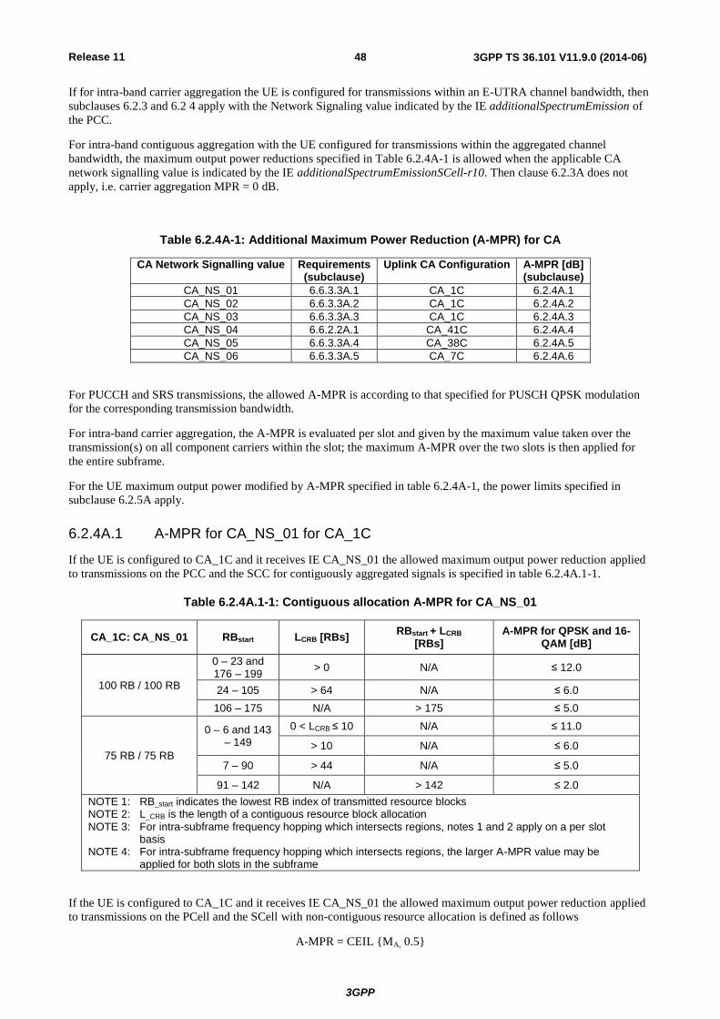
For intra-band contiguous aggregation with the UE configured for transmissions within the aggregated channel
bandwidth, the maximum output power reductions specified in Table 6.2.4A-1 is allowed when the applicable CA
network signalling value is indicated by the IE additionalSpectrumEmissionSCell-r10. Then clause 6.2.3A does not
apply, i.e. carrier aggregation MPR = 0 dB.
Table 6.2.4A-1: Additional Maximum Power Reduction (A-MPR) for CA
CA Network Signalling value Requirements (subclause)
Uplink CA Configuration A-MPR [dB] (subclause)
CA_NS_01 6.6.3.3A.1 CA_1C 6.2.4A.1
CA_NS_02 6.6.3.3A.2 CA_1C 6.2.4A.2
CA_NS_03 6.6.3.3A.3 CA_1C 6.2.4A.3
CA_NS_04 6.6.2.2A.1 CA_41C 6.2.4A.4
CA_NS_05 6.6.3.3A.4 CA_38C 6.2.4A.5
CA_NS_06 6.6.3.3A.5 CA_7C 6.2.4A.6
For PUCCH and SRS transmissions, the allowed A-MPR is according to that specified for PUSCH QPSK modulation
for the corresponding transmission bandwidth.
For intra-band carrier aggregation, the A-MPR is evaluated per slot and given by the maximum value taken over the
transmission(s) on all component carriers within the slot; the maximum A-MPR over the two slots is then applied for
the entire subframe.
For the UE maximum output power modified by A-MPR specified in table 6.2.4A-1, the power limits specified in
subclause 6.2.5A apply.
6.2.4A.1 A-MPR for CA_NS_01 for CA_1C
If the UE is configured to CA_1C and it receives IE CA_NS_01 the allowed maximum output power reduction applied
to transmissions on the PCC and the SCC for contiguously aggregated signals is specified in table 6.2.4A.1-1.
Table 6.2.4A.1-1: Contiguous allocation A-MPR for CA_NS_01
CA_1C: CA_NS_01 RBstart LCRB [RBs] RBstart + LCRB
[RBs] A-MPR for QPSK and 16-
QAM [dB]
100 RB / 100 RB
0 – 23 and 176 – 199
> 0 N/A ≤ 12.0
24 – 105 > 64 N/A ≤ 6.0
106 – 175 N/A > 175 ≤ 5.0
75 RB / 75 RB
0 – 6 and 143 – 149
0 < LCRB ≤ 10 N/A ≤ 11.0
> 10 N/A ≤ 6.0
7 – 90 > 44 N/A ≤ 5.0
91 – 142 N/A > 142 ≤ 2.0
NOTE 1: RB_start indicates the lowest RB index of transmitted resource blocks NOTE 2: L_CRB is the length of a contiguous resource block allocation NOTE 3: For intra-subframe frequency hopping which intersects regions, notes 1 and 2 apply on a per slot
basis NOTE 4: For intra-subframe frequency hopping which intersects regions, the larger A-MPR value may be
applied for both slots in the subframe
If the UE is configured to CA_1C and it receives IE CA_NS_01 the allowed maximum output power reduction applied
to transmissions on the PCell and the SCell with non-contiguous resource allocation is defined as follows
A-MPR = CEIL {MA, 0.5}

Release 11
3GPP
3GPP TS 36.101 V11.9.0 (2014-06) 49
Where MA is defined as follows
MA = -22.5 A + 17 ; 0 ≤ A < 0.20
-11.0 A + 14.7 ; 0.20 ≤ A < 0.70
-1.7 A + 8.2 ; 0.70 ≤ A ≤ 1
Where A = NRB_alloc / NRB_agg.
6.2.4A.2 A-MPR for CA_NS_02 for CA_1C
If the UE is configured to CA_1C and it receives IE CA_NS_02 the allowed maximum output power reduction applied
to transmission on the PCC and the SCC for contiguously aggregated signals is specified in Table 6.2.4A.2-1.
Table 6.2.4A.2-1: Contiguous allocation A-MPR for CA_NS_02
CA_1C: CA_NS_02 RBend LCRB [RBs] A-MPR for QPSK and
16 –QAM [dB]
100 RB / 100 RB
0 –20 > 0 ≤ 4 dB
21 – 46 > 0 ≤ 3 dB
47 – 99 > RBend - 20 ≤ 3 dB
100 – 184 > 75 ≤ 6 dB
185 – 199 > 0 ≤ 10 dB
75 RB / 75 RB
0 – 48 > 0 ≤ 2 dB
49 – 80 > RBend - 20 ≤ 3 dB
81 – 129 > 60 ≤ 5 dB
130 – 149 > 84 ≤ 6 dB
130 – 149 1 – 84 ≤ 2 dB
If the UE is configured to CA_1C and it receives IE CA_NS_02 the allowed maximum output power reduction applied
to transmissions on the PCell and the SCell with non-contiguous resource allocation is defined as follows:
A-MPR = CEIL {MA, 0.5}
Where MA is defined as follows
[MA = -22.5 A + 17 ; 0 ≤ A < 0.20
-11.0 A + 14.7 ; 0.20 ≤ A < 0.70
-1.7 A + 8.2 ; 0.70 ≤ A ≤ 1]
Where A = NRB_alloc / NRB_agg.
6.2.4A.3 A-MPR for CA_NS_03 for CA_1C
If the UE is configured to CA_1C and it receives IE CA_NS_03 the allowed maximum output power reduction applied
to transmission on the PCC and the SCC for contiguously aggregated signals is specified in Table 6.2.4A.3-1.

Release 11
3GPP
3GPP TS 36.101 V11.9.0 (2014-06) 50
Table 6.2.4A.3-1: Contiguous allocation A-MPR for CA_NS_03
CA_1C: CA_NS_03 RBend LCRB [RBs] A-MPR for QPSK and
16-QAM [dB]
100 RB / 100 RB
0 – 26 > 0 ≤ 10 dB
27 – 63 ≥ RBend - 27 ≤ 6 dB
27 – 63 < RBend - 27 ≤ 1 dB
64 – 100 > RBend - 20 ≤ 4 dB
101 – 171 > 68 ≤ 7 dB
172 – 199 > 0 ≤ 10 dB
75 RB / 75 RB
0 – 20 > 0 ≤ 10 dB
21 – 45 > 0 ≤ 4 dB
46 – 75 > RBend – 13 ≤ 2 dB
76 – 95 > 45 ≤ 5 dB
96 – 149 > 43 ≤ 8 dB
120 – 149 1 - 43 ≤ 6 dB
If the UE is configured to CA_1C and it receives IE CA_NS_03 the allowed maximum output power reduction applied
to transmissions on the PCell and the SCell with non-contiguous resource allocation is defined as follows:
A-MPR = CEIL {MA, 0.5}
Where MA is defined as follows
[MA = -23.33A + 17.5 ; 0 ≤ A < 0.15
-7.65A + 15.15 ; 0.15 ≤ A ≤ 1]
Where A = NRB_alloc / NRB_agg.
6.2.4A.4 A-MPR for CA_NS_04
If the UE is configured to CA_41C and it receives IE CA_NS_04 the allowed maximum output power reduction applied
to transmission on the PCC and the SCC for contiguously aggregated signals is specified in Table 6.2.4A.4-1.
Table 6.2.4A.4-1: Contigous Allocation A-MPR for CA_NS_04
CA Bandwidth Class C
RBStart LCRB [RBs]
RBstart + LCRB [RBs]
A-MPR for QPSK [dB]
A-MPR for 16QAM [dB]
50RB / 100 RB 0 – 44 and 105 – 149 >0 N/A ≤4dB ≤4dB
45 – 104 N/A >105 ≤3dB ≤4dB
75 RB / 75 RB 0 – 44 and 105 – 149 >0 N/A ≤4dB ≤4dB
45 – 104 N/A >105 ≤4dB ≤4dB
100 RB / 75 RB 0 – 49 and 125 – 174 >0 N/A ≤4dB ≤4dB
50 - 124 N/A >125 ≤3dB ≤4dB
100 RB / 100 RB 0 – 59 and 140 – 199 >0 N/A ≤3dB ≤4dB
60– 139 N/A >140 ≤3dB ≤4dB
NOTE 1: RBstart indicates the lowest RB index of transmitted resource blocks NOTE 2: LCRB is the length of a contiguous resource block allocation NOTE 3: For intra-subframe frequency hopping which intersects regions, notes 1 and 2 apply on a per slot basis NOTE 4: For intra-subframe frequency hopping which intersects regions, the larger A-MPR value may be applied
for both slots in the subframe
If the UE is configured to CA_41C and it receives IE CA_NS_04 the allowed maximum output power reduction applied
to transmissions on the PCell and the SCell with non-contiguous resource allocation is defined as follows
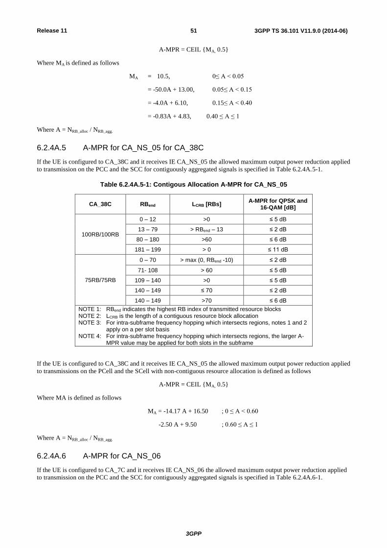
Release 11
3GPP
3GPP TS 36.101 V11.9.0 (2014-06) 51
A-MPR = CEIL {MA, 0.5}
Where MA is defined as follows
MA = 10.5, 0≤ A < 0.05
= -50.0A + 13.00, 0.05≤ A < 0.15
= -4.0A + 6.10, 0.15≤ A < 0.40
= -0.83A + 4.83, 0.40 ≤ A ≤ 1
Where A = NRB_alloc / NRB_agg.
6.2.4A.5 A-MPR for CA_NS_05 for CA_38C
If the UE is configured to CA_38C and it receives IE CA_NS_05 the allowed maximum output power reduction applied
to transmission on the PCC and the SCC for contiguously aggregated signals is specified in Table 6.2.4A.5-1.
Table 6.2.4A.5-1: Contigous Allocation A-MPR for CA_NS_05
CA_38C RBend LCRB [RBs] A-MPR for QPSK and
16-QAM [dB]
100RB/100RB
0 – 12 >0 ≤ 5 dB
13 – 79 > RBend – 13 ≤ 2 dB
80 – 180 >60 ≤ 6 dB
181 – 199 > 0 ≤ 11 dB
75RB/75RB
0 – 70 > max (0, RBend -10) ≤ 2 dB
71- 108 > 60 ≤ 5 dB
109 – 140 >0 ≤ 5 dB
140 – 149 ≤ 70 ≤ 2 dB
140 – 149 >70 ≤ 6 dB
NOTE 1: RBend indicates the highest RB index of transmitted resource blocks NOTE 2: LCRB is the length of a contiguous resource block allocation NOTE 3: For intra-subframe frequency hopping which intersects regions, notes 1 and 2
apply on a per slot basis NOTE 4: For intra-subframe frequency hopping which intersects regions, the larger A-
MPR value may be applied for both slots in the subframe
If the UE is configured to CA_38C and it receives IE CA_NS_05 the allowed maximum output power reduction applied
to transmissions on the PCell and the SCell with non-contiguous resource allocation is defined as follows
A-MPR = CEIL {MA, 0.5}
Where MA is defined as follows
MA = -14.17 A + 16.50 ; 0 ≤ A < 0.60
-2.50 A + 9.50 ; 0.60 ≤ A ≤ 1
Where A = NRB_alloc / NRB_agg.
6.2.4A.6 A-MPR for CA_NS_06
If the UE is configured to CA_7C and it receives IE CA_NS_06 the allowed maximum output power reduction applied
to transmission on the PCC and the SCC for contiguously aggregated signals is specified in Table 6.2.4A.6-1.

Release 11
3GPP
3GPP TS 36.101 V11.9.0 (2014-06) 52
Table 6.2.4A.6-1: Contiguous Allocation A-MPR for CA_NS_06
CA Bandwidth Class C
RB_end LCRB [RBs] A-MPR for QPSK and
16-QAM [dB]
100RB/100RB
0 –22 >0 ≤[4 dB
23 – 105 > RBend – 10 ≤ 2 dB
106 – 142 > 75 ≤ 3 dB
143 – 177 >70 ≤ 5 dB
178 – 199 > 0 ≤ 10 dB
75RB/75RB
0 – 7 >0 ≤ 5 dB
20- 74 > RBend – 10 ≤ 2 dB
75 – 109 >64 ≤ 2 dB
110 – 144 >35 ≤ 6 dB
145 – 149 >0 ≤ 10 dB
If the UE is configured to CA_7C and it receives IE CA_NS_06 the allowed maximum output power reduction applied
to transmissions on the PCell and the SCell with non-contiguous resource allocation is defined as follows:
A-MPR = CEIL {MA, 0.5}
Where MA is defined as follows
MA = -23.33A + 17.5 ; 0 ≤ A < 0.15
-7.65A + 15.15 ; 0.15 ≤ A ≤ 1
Where A = NRB_alloc / NRB_agg.
6.2.4B UE maximum output power with additional requirements for UL-MIMO
For UE with two transmit antenna connectors in closed-loop spatial multiplexing scheme, the A-MPR values specified
in subclause 6.2.4 shall apply to the maximum output power specified in Table 6.2.2B-1. The requirements shall be met
with the UL-MIMO configurations specified in Table 6.2.2B-2. For UE supporting UL-MIMO, the maximum output
power is measured as the sum of the maximum output power at each UE antenna connector. Unless stated otherwise, an
A-MPR of 0 dB shall be used.
For the UE maximum output power modified by A-MPR, the power limits specified in subclause 6.2.5B apply.
For single-antenna port scheme, the requirements in subclause 6.2.4 apply.
6.2.5 Configured transmitted power
The UE is allowed to set its configured maximum output power PCMAX,c for serving cell c. The configured maximum
output power PCMAX,c is set within the following bounds:
PCMAX_L,c ≤ PCMAX,c ≤ PCMAX_H,c
with
PCMAX_L,c = MIN {PEMAX,c – TC,c, PPowerClass – MAX(MPRc + A-MPRc + ΔTIB,c + TC,c, P-MPRc) }
PCMAX_H,c = MIN {PEMAX,c, PPowerClass}
where
- PEMAX,c is the value given by IE P-Max for serving cell c, defined in [7];
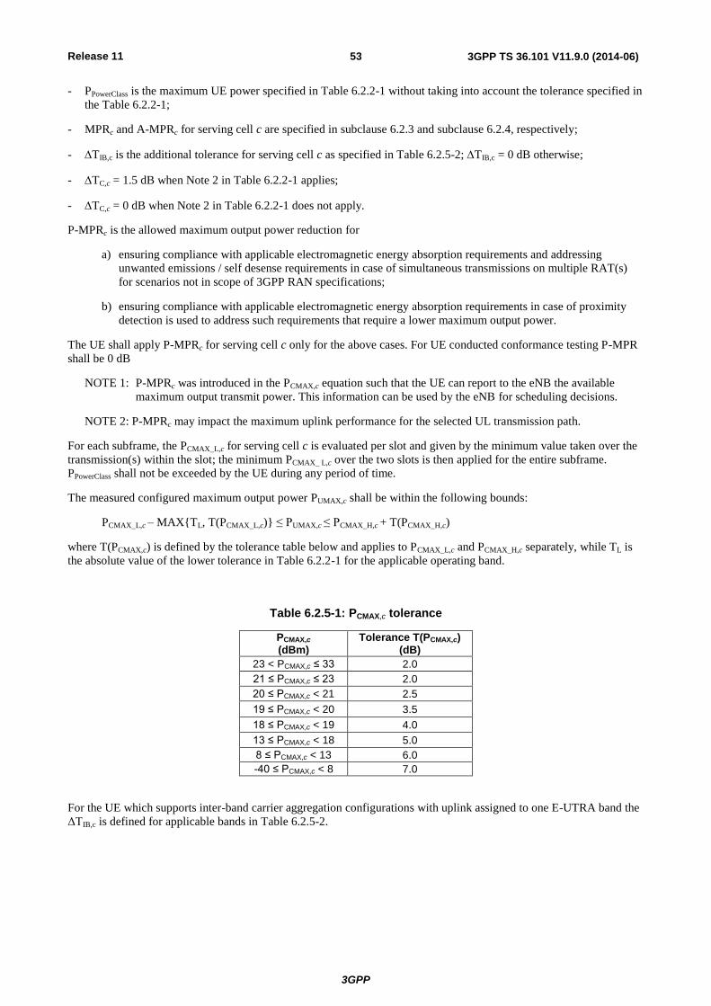
Release 11
3GPP
3GPP TS 36.101 V11.9.0 (2014-06) 53
- PPowerClass is the maximum UE power specified in Table 6.2.2-1 without taking into account the tolerance specified in
the Table 6.2.2-1;
- MPRc and A-MPRc for serving cell c are specified in subclause 6.2.3 and subclause 6.2.4, respectively;
- TIB,c is the additional tolerance for serving cell c as specified in Table 6.2.5-2; TIB,c = 0 dB otherwise;
- TC,c = 1.5 dB when Note 2 in Table 6.2.2-1 applies;
- TC,c = 0 dB when Note 2 in Table 6.2.2-1 does not apply.
P-MPRc is the allowed maximum output power reduction for
a) ensuring compliance with applicable electromagnetic energy absorption requirements and addressing
unwanted emissions / self desense requirements in case of simultaneous transmissions on multiple RAT(s)
for scenarios not in scope of 3GPP RAN specifications;
b) ensuring compliance with applicable electromagnetic energy absorption requirements in case of proximity
detection is used to address such requirements that require a lower maximum output power.
The UE shall apply P-MPRc for serving cell c only for the above cases. For UE conducted conformance testing P-MPR
shall be 0 dB
NOTE 1: P-MPRc was introduced in the PCMAX,c equation such that the UE can report to the eNB the available
maximum output transmit power. This information can be used by the eNB for scheduling decisions.
NOTE 2: P-MPRc may impact the maximum uplink performance for the selected UL transmission path.
For each subframe, the PCMAX_L,c for serving cell c is evaluated per slot and given by the minimum value taken over the
transmission(s) within the slot; the minimum PCMAX_ L,c over the two slots is then applied for the entire subframe.
PPowerClass shall not be exceeded by the UE during any period of time.
The measured configured maximum output power PUMAX,c shall be within the following bounds:
PCMAX_L,c – MAX{TL, T(PCMAX_L,c)} ≤ PUMAX,c ≤ PCMAX_H,c + T(PCMAX_H,c)
where T(PCMAX,c) is defined by the tolerance table below and applies to PCMAX_L,c and PCMAX_H,c separately, while TL is
the absolute value of the lower tolerance in Table 6.2.2-1 for the applicable operating band.
Table 6.2.5-1: PCMAX,c tolerance
PCMAX,c
(dBm) Tolerance T(PCMAX,c)
(dB)
23 < PCMAX,c ≤ 33 2.0
21 ≤ PCMAX,c ≤ 23 2.0
20 ≤ PCMAX,c < 21 2.5
19 ≤ PCMAX,c < 20 3.5
18 ≤ PCMAX,c < 19 4.0
13 ≤ PCMAX,c < 18 5.0
8 ≤ PCMAX,c < 13 6.0
-40 ≤ PCMAX,c < 8 7.0
For the UE which supports inter-band carrier aggregation configurations with uplink assigned to one E-UTRA band the
ΔTIB,c is defined for applicable bands in Table 6.2.5-2.

Release 11
3GPP
3GPP TS 36.101 V11.9.0 (2014-06) 54
Table 6.2.5-2: ΔTIB,c
Inter-band CA Configuration
E-UTRA Band ΔTIB,c [dB]
CA_1A-5A 1 0.3
5 0.3
CA_1A-18A 1 0.3
18 0.3
CA_1A-19A 1 0.3
19 0.3
CA_1A-21A 1 0.3
21 0.3
CA_2A-17A 2 0.3
17 0.8
CA_2A-29A 2 0.3
CA_3A-5A 3 0.3
5 0.3
CA_3A-7A 3 0.5
7 0.5
CA_3A-8A 3 0.3
8 0.3
CA_3A-20A 3 0.3
20 0.3
CA_4A-5A 4 0.3
5 0.3
CA_4A-7A 4 0.5
7 0.5
CA_4A-12A 4 0.3
12 0.8
CA_4A-13A 4 0.3
13 0.3
CA_4A-17A 4 0.3
17 0.8
CA_4A-29A 4 0.3
CA_5A-12A 5 0.8
12 0.4
CA_5A-17A 5 0.8
17 0.4
CA_7A-20A 7 0.3
20 0.3
CA_8A-20A 8 0.4
20 0.4
CA_11A-18A 11 0.3
18 0.3
NOTE 1: The above additional tolerances are only applicable for the E-UTRA operating bands that belong to the supported inter-band carrier aggregation configurations
NOTE 2: The above additional tolerances also apply in non-aggregated operation for the supported E-UTRA operating bands that belong to the supported inter-band carrier aggregation configurations
NOTE 3: In case the UE supports more than one of the above inter-band carrier aggregation configurations and a E-UTRA operating band belongs to more than one inter-band carrier aggregation configurations then:
- When the E-UTRA operating band frequency range is ≤ 1GHz, the
applicable additional tolerance shall be the average of the tolerances above,
truncated to one decimal place for that operating band among the supported
CA configurations. In case there is a harmonic relation between low band
UL and high band DL, then the maximum tolerance among the different
supported carrier aggregation configurations involving such band shall be
applied
- When the E-UTRA operating band frequency range is >1GHz, the
applicable additional tolerance shall be the maximum tolerance above that
applies for that operating band among the supported CA configurations

Release 11
3GPP
3GPP TS 36.101 V11.9.0 (2014-06) 55
NOTE: The above additional tolerances do not apply to supported UTRA operating bands with frequency range
below 1 GHz that correspond to the E-UTRA operating bands that belong to the supported inter-band
carrier aggregation configurations when such bands are belonging only to band combination(s) where one
band is <1GHz and another band is >1.7GHz and there is no harmonic relationship between the low band
UL and high band DL. Otherwise the above additional tolerances also apply to supported UTRA
operating bands that correspond to the E-UTRA operating bands that belong to the supported inter-band
carrier aggregation configurations.
NOTE: To meet the TIB,c requirements for CA_3A-7A with state-of-the-art technology, an increase in power
consumption of the UE may be required. It is also expected that as the state-of-the-art technology evolves
in the future, this possible power consumption increase can be reduced or eliminated.
6.2.5A Configured transmitted power for CA
For uplink carrier aggregation the UE is allowed to set its configured maximum output power PCMAX,c for serving cell c
and its total configured maximum output power PCMAX.
The configured maximum output power PCMAX,c on serving cell c shall be set as specified in subclause 6.2.5.
For uplink inter-band carrier aggregation, MPRc and A-MPRc apply per serving cell c and are specified in subclause
6.2.3 and subclause 6.2.4, respectively. P-MPR c accounts for power management for serving cell c. PCMAX,c is
calculated under the assumption that the transmit power is increased independently on all component carriers.
For uplink intra-band contiguous carrier aggregation, MPRc = MPR and A-MPRc = A-MPR with MPR and A-MPR
specified in subclause 6.2.3A and subclause 6.2.4A respectively. There is one power management term for the UE,
denoted P-MPR, and P-MPR c = P-MPR. PCMAX,c is calculated under the assumption that the transmit power is
increased by the same amount in dB on all component carriers.
Table 6.2.5A-1:Void
The total configured maximum output power PCMAX shall be set within the following bounds:
PCMAX_L ≤ PCMAX ≤ PCMAX_H
For uplink inter-band carrier aggregation with one serving cell c per operating band,
PCMAX_L = MIN {10log10∑ MIN [ pEMAX,c/ (tC,c), pPowerClass/(mprc·a-mprc·tC,c ·tIB,c) , pPowerClass/pmprc], PPowerClass}
PCMAX_H = MIN{10 log10 ∑ pEMAX,c , PPowerClass}
where
- pEMAX,c is the linear value of PEMAX, c which is given by IE P-Max for serving cell c in [7];
- PPowerClass is the maximum UE power specified in Table 6.2.2A-1 without taking into account the tolerance specified
in the Table 6.2.2A-1; pPowerClass is the linear value of PPowerClass;
- mpr c and a-mpr c are the linear values of MPR c and A-MPR c as specified in subclause 6.2.3 and subclause 6.2.4,
respectively;
- pmprc is the linear value of P-MPR c;
- tC,c is the linear value of TC,ctC,c = 1.41 when Note 2 in Table 6.2.2-1 applies for a serving cell c, otherwise
tC,c = 1;
- tIB,c is the linear value of the inter-band relaxation term TIB,c of the serving cell c as specified in Table 6.2.5-2;
otherwise tIB,c.
For uplink intra-band contiguous carrier aggregation,
PCMAX_L = MIN{10 log10 ∑ pEMAX,c - TC , PPowerClass – MAX(MPR + A-MPR + ΔTIB,c + TC, P-MPR)}
PCMAX_H = MIN{10 log10 ∑ pEMAX,c , PPowerClass}
where
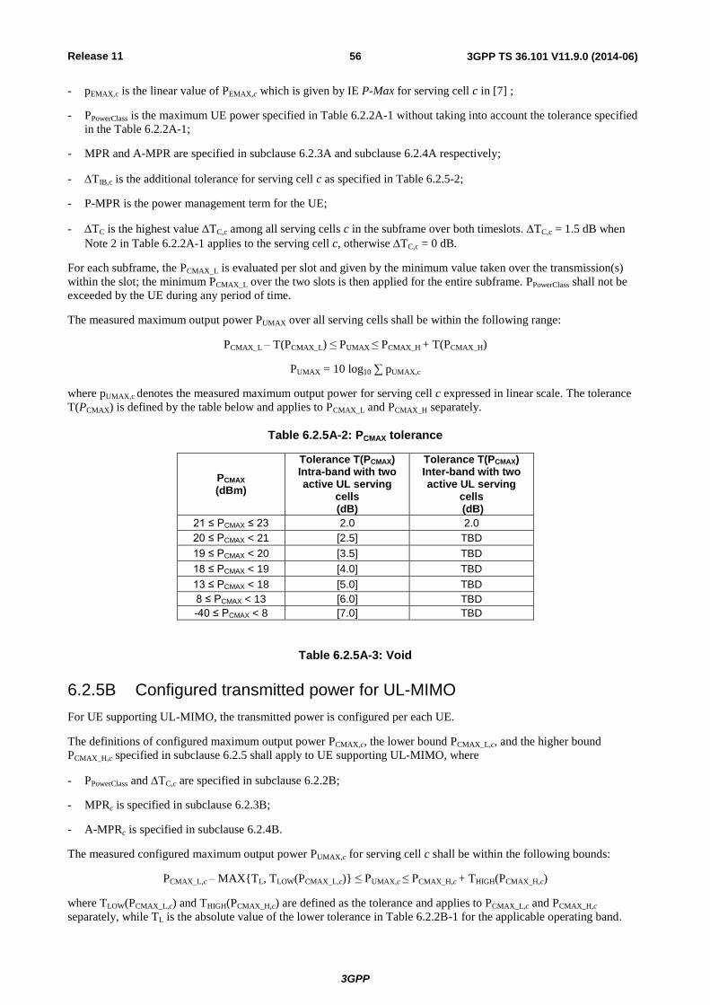
Release 11
3GPP
3GPP TS 36.101 V11.9.0 (2014-06) 56
- pEMAX,c is the linear value of PEMAX,c which is given by IE P-Max for serving cell c in [7] ;
- PPowerClass is the maximum UE power specified in Table 6.2.2A-1 without taking into account the tolerance specified
in the Table 6.2.2A-1;
- MPR and A-MPR are specified in subclause 6.2.3A and subclause 6.2.4A respectively;
- TIB,c is the additional tolerance for serving cell c as specified in Table 6.2.5-2;
- P-MPR is the power management term for the UE;
- TC is the highest value TC,c among all serving cells c in the subframe over both timeslots. TC,c = 1.5 dB when
Note 2 in Table 6.2.2A-1 applies to the serving cell c, otherwise TC,c = 0 dB.
For each subframe, the PCMAX_L is evaluated per slot and given by the minimum value taken over the transmission(s)
within the slot; the minimum PCMAX_L over the two slots is then applied for the entire subframe. PPowerClass shall not be
exceeded by the UE during any period of time.
The measured maximum output power PUMAX over all serving cells shall be within the following range:
PCMAX_L – T(PCMAX_L) ≤ PUMAX ≤ PCMAX_H + T(PCMAX_H)
PUMAX = 10 log10 ∑ pUMAX,c
where pUMAX,c denotes the measured maximum output power for serving cell c expressed in linear scale. The tolerance
T(PCMAX) is defined by the table below and applies to PCMAX_L and PCMAX_H separately.
Table 6.2.5A-2: PCMAX tolerance
PCMAX
(dBm)
Tolerance T(PCMAX) Intra-band with two active UL serving
cells (dB)
Tolerance T(PCMAX) Inter-band with two active UL serving
cells (dB)
21 ≤ PCMAX ≤ 23 2.0 2.0
20 ≤ PCMAX < 21 [2.5] TBD
19 ≤ PCMAX < 20 [3.5] TBD
18 ≤ PCMAX < 19 [4.0] TBD
13 ≤ PCMAX < 18 [5.0] TBD
8 ≤ PCMAX < 13 [6.0] TBD
-40 ≤ PCMAX < 8 [7.0] TBD
Table 6.2.5A-3: Void
6.2.5B Configured transmitted power for UL-MIMO
For UE supporting UL-MIMO, the transmitted power is configured per each UE.
The definitions of configured maximum output power PCMAX,c, the lower bound PCMAX_L,c, and the higher bound
PCMAX_H,c specified in subclause 6.2.5 shall apply to UE supporting UL-MIMO, where
- PPowerClass and TC,c are specified in subclause 6.2.2B;
- MPRc is specified in subclause 6.2.3B;
- A-MPRc is specified in subclause 6.2.4B.
The measured configured maximum output power PUMAX,c for serving cell c shall be within the following bounds:
PCMAX_L,c – MAX{TL, TLOW(PCMAX_L,c)} ≤ PUMAX,c ≤ PCMAX_H,c + THIGH(PCMAX_H,c)
where TLOW(PCMAX_L,c) and THIGH(PCMAX_H,c) are defined as the tolerance and applies to PCMAX_L,c and PCMAX_H,c
separately, while TL is the absolute value of the lower tolerance in Table 6.2.2B-1 for the applicable operating band.

Release 11
3GPP
3GPP TS 36.101 V11.9.0 (2014-06) 57
For UE with two transmit antenna connectors in closed-loop spatial amultiplexing scheme, the tolerance is specified in
Table 6.2.5B-1. The requirements shall be met with UL-MIMO configurations specified in Table 6.2.2B-2.
Table 6.2.5B-1: PCMAX,c tolerance in closed-loop spatial multiplexing scheme
PCMAX,c
(dBm) Tolerance
TLOW(PCMAX_L,c) (dB) Tolerance
THIGH(PCMAX_H,c) (dB)
PCMAX,c = 23 3.0 2.0
[22] ≤ PCMAX,c < [23] [5.0] [2.0]
[21] ≤ PCMAX,c < [22] [5.0] [3.0]
[20] ≤ PCMAX,c < [21] [6.0] [4.0]
[16] ≤ PCMAX,c < [20] [5.0]
[11] ≤ PCMAX,c < [16] [6.0]
[-40] ≤ PCMAX,c <
[11] [7.0]
For single-antenna port scheme, the requirements in subclause 6.2.5 apply.
6.3 Output power dynamics
6.3.1 (Void)
6.3.2 Minimum output power
The minimum controlled output power of the UE is defined as the broadband transmit power of the UE, i.e. the power
in the channel bandwidth for all transmit bandwidth configurations (resource blocks), when the power is set to a
minimum value.
6.3.2.1 Minimum requirement
The minimum output power is defined as the mean power in one sub-frame (1ms). The minimum output power shall not
exceed the values specified in Table 6.3.2.1-1.
Table 6.3.2.1-1: Minimum output power
Channel bandwidth / Minimum output power / Measurement bandwidth
1.4 MHz
3.0 MHz
5 MHz
10 MHz
15 MHz
20 MHz
Minimum output power
-40 dBm
Measurement bandwidth
1.08 MHz 2.7 MHz 4.5 MHz 9.0 MHz 13.5 MHz 18 MHz
6.3.2A UE Minimum output power for CA
For intra-band contiguous carrier aggregation, the minimum controlled output power of the UE is defined as the
transmit power of the UE per component carrier, i.e., the power in the channel bandwidth of each component carrier for
all transmit bandwidth configurations (resource blocks), when the power on both component carriers are set to a
minimum value.
6.3.2A.1 Minimum requirement for CA
For intra-band contiguous carrier aggregation the minimum output power is defined as the mean power in one sub-
frame (1ms). The minimum output power shall not exceed the values specified in Table 6.3.2A.1-1.
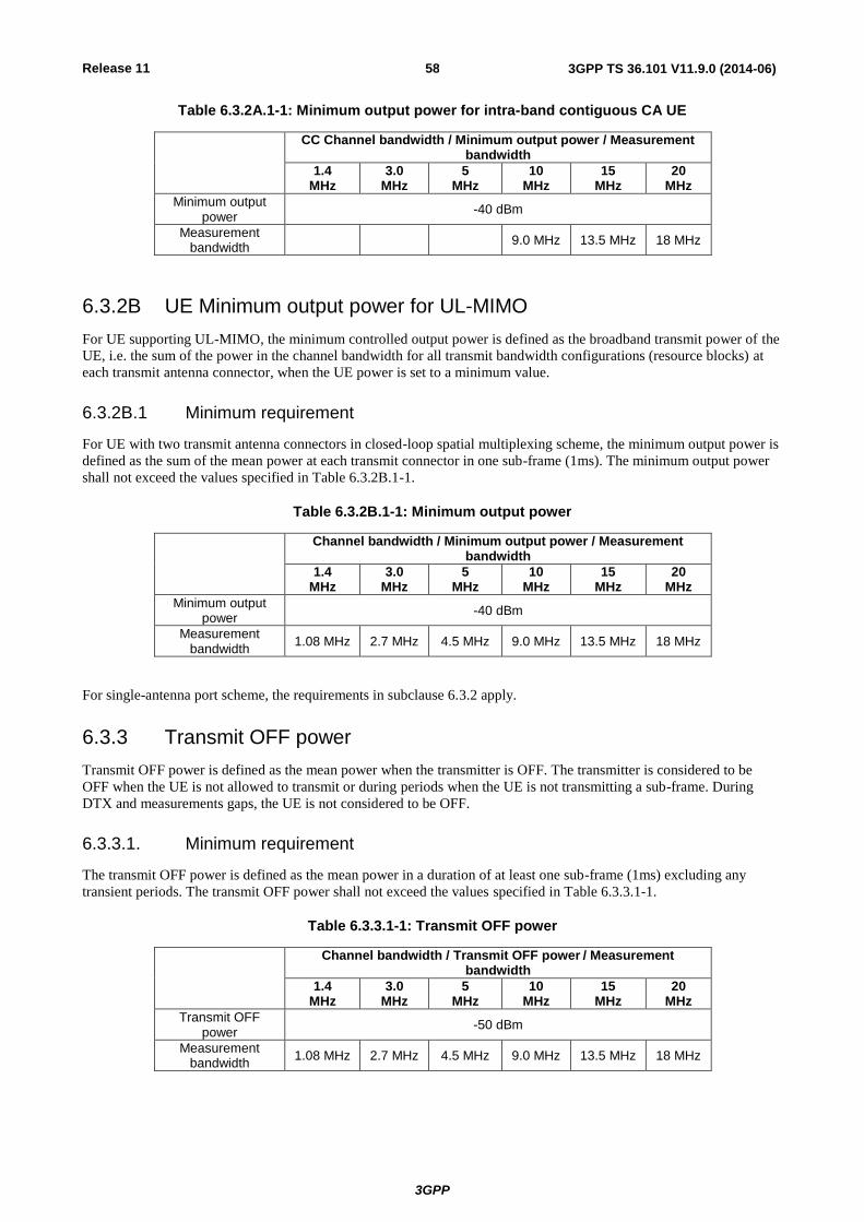
Release 11
3GPP
3GPP TS 36.101 V11.9.0 (2014-06) 58
Table 6.3.2A.1-1: Minimum output power for intra-band contiguous CA UE
CC Channel bandwidth / Minimum output power / Measurement bandwidth
1.4 MHz
3.0 MHz
5 MHz
10 MHz
15 MHz
20 MHz
Minimum output power
-40 dBm
Measurement bandwidth
9.0 MHz 13.5 MHz 18 MHz
6.3.2B UE Minimum output power for UL-MIMO
For UE supporting UL-MIMO, the minimum controlled output power is defined as the broadband transmit power of the
UE, i.e. the sum of the power in the channel bandwidth for all transmit bandwidth configurations (resource blocks) at
each transmit antenna connector, when the UE power is set to a minimum value.
6.3.2B.1 Minimum requirement
For UE with two transmit antenna connectors in closed-loop spatial multiplexing scheme, the minimum output power is
defined as the sum of the mean power at each transmit connector in one sub-frame (1ms). The minimum output power
shall not exceed the values specified in Table 6.3.2B.1-1.
Table 6.3.2B.1-1: Minimum output power
Channel bandwidth / Minimum output power / Measurement bandwidth
1.4 MHz
3.0 MHz
5 MHz
10 MHz
15 MHz
20 MHz
Minimum output power
-40 dBm
Measurement bandwidth
1.08 MHz 2.7 MHz 4.5 MHz 9.0 MHz 13.5 MHz 18 MHz
For single-antenna port scheme, the requirements in subclause 6.3.2 apply.
6.3.3 Transmit OFF power
Transmit OFF power is defined as the mean power when the transmitter is OFF. The transmitter is considered to be
OFF when the UE is not allowed to transmit or during periods when the UE is not transmitting a sub-frame. During
DTX and measurements gaps, the UE is not considered to be OFF.
6.3.3.1. Minimum requirement
The transmit OFF power is defined as the mean power in a duration of at least one sub-frame (1ms) excluding any
transient periods. The transmit OFF power shall not exceed the values specified in Table 6.3.3.1-1.
Table 6.3.3.1-1: Transmit OFF power
Channel bandwidth / Transmit OFF power / Measurement bandwidth
1.4 MHz
3.0 MHz
5 MHz
10 MHz
15 MHz
20 MHz
Transmit OFF power
-50 dBm
Measurement bandwidth
1.08 MHz 2.7 MHz 4.5 MHz 9.0 MHz 13.5 MHz 18 MHz

Release 11
3GPP
3GPP TS 36.101 V11.9.0 (2014-06) 59
6.3.3A UE Transmit OFF power for CA
For intra-band contiguous carrier aggregation, transmit OFF power is defined as the mean power per component carrier
when the transmitter is OFF on both component carriers. The transmitter is considered to be OFF when the UE is not
allowed to transmit or during periods when the UE is not transmitting a sub-frame. During measurements gaps, the UE
is not considered to be OFF.
6.3.3A.1 Minimum requirement for CA
For intra-band contiguous carrier aggregation the transmit OFF power is defined as the mean power in a duration of at
least one sub-frame (1ms) excluding any transient periods. The transmit OFF power shall not exceed the values
specified in Table 6.3.3A.1-1.
Table 6.3.3A.1-1: Transmit OFF power for intra-band contiguous CA UE
Channel bandwidth / Transmit OFF power / Measurement bandwidth
1.4 MHz
3.0 MHz
5 MHz
10 MHz
15 MHz
20 MHz
Transmit OFF power
-50 dBm
Measurement bandwidth
9.0 MHz 13.5 MHz 18 MHz
6.3.3B UE Transmit OFF power for UL-MIMO
For UE supporting UL-MIMO, the transmit OFF power is defined as the mean power at each transmit antenna
connector when the transmitter is OFF at all transmit antenna connectors. The transmitter is considered to be OFF when
the UE is not allowed to transmit or during periods when the UE is not transmitting a sub-frame. During DTX and
measurements gaps, the UE is not considered to be OFF.
6.3.3B.1 Minimum requirement
The transmit OFF power is defined as the mean power at each transmit antenna connector in a duration of at least one
sub-frame (1ms) excluding any transient periods. The transmit OFF power at each transmit antenna connector shall not
exceed the values specified in Table 6.3.3B.1-1.
Table 6.3.3B.1-1: Transmit OFF power per antenna port
Channel bandwidth / Transmit OFF power/ Measurement bandwidth
1.4 MHz
3.0 MHz
5 MHz
10 MHz
15 MHz
20 MHz
Transmit OFF power
-50 dBm
Measurement bandwidth
1.08 MHz 2.7 MHz 4.5 MHz 9.0 MHz 13.5 MHz 18 MHz
6.3.4 ON/OFF time mask
6.3.4.1 General ON/OFF time mask
The General ON/OFF time mask defines the observation period between Transmit OFF and ON power and between
Transmit ON and OFF power. ON/OFF scenarios include; the beginning or end of DTX, measurement gap, contiguous,
and non contiguous transmission
The OFF power measurement period is defined in a duration of at least one sub-frame excluding any transient periods.
The ON power is defined as the mean power over one sub-frame excluding any transient period.
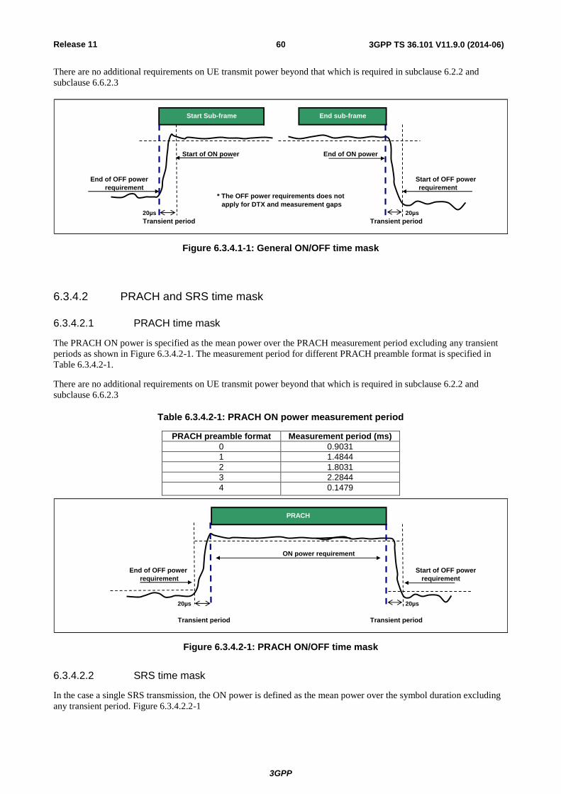
Release 11
3GPP
3GPP TS 36.101 V11.9.0 (2014-06) 60
There are no additional requirements on UE transmit power beyond that which is required in subclause 6.2.2 and
subclause 6.6.2.3
End of OFF power
20µs 20µs
Transient period Transient period
Start of OFF power
Start of ON power
requirement
Start Sub-frame End sub-frame
End of ON power
requirement
* The OFF power requirements does not
apply for DTX and measurement gaps
Figure 6.3.4.1-1: General ON/OFF time mask
6.3.4.2 PRACH and SRS time mask
6.3.4.2.1 PRACH time mask
The PRACH ON power is specified as the mean power over the PRACH measurement period excluding any transient
periods as shown in Figure 6.3.4.2-1. The measurement period for different PRACH preamble format is specified in
Table 6.3.4.2-1.
There are no additional requirements on UE transmit power beyond that which is required in subclause 6.2.2 and
subclause 6.6.2.3
Table 6.3.4.2-1: PRACH ON power measurement period
PRACH preamble format Measurement period (ms)
0 0.9031
1 1.4844
2 1.8031
3 2.2844
4 0.1479
ON power requirement
requirement
20µs 20µs
Transient period Transient period
PRACH
End of OFF power Start of OFF power
requirement
Figure 6.3.4.2-1: PRACH ON/OFF time mask
6.3.4.2.2 SRS time mask
In the case a single SRS transmission, the ON power is defined as the mean power over the symbol duration excluding
any transient period. Figure 6.3.4.2.2-1

Release 11
3GPP
3GPP TS 36.101 V11.9.0 (2014-06) 61
In the case a dual SRS transmission, the ON power is defined as the mean power for each symbol duration excluding
any transient period. Figure 6.3.4.2.2-2
There are no additional requirements on UE transmit power beyond that which is required in subclause 6.2.2 and
subclause 6.6.2.3
requirement
20µs 20µs
Transient period Transient period
End of OFF
power requirement
SRS
SRS ON power
requirement
Start of OFF power
Figure 6.3.4.2.2-1: Single SRS time mask
End of OFF
20µs 20µs 20µs 20µs
* Transient period is only specifed in the case of frequency hopping or a power change between SRS symbols
*Transient periodTransient period
SRS SRS
requirement
Transient period
Start of OFF power
power requirement
SRS ON power
requirement
SRS ON power
requirement
Figure 6.3.4.2.2-2: Dual SRS time mask for the case of UpPTS transmissions
6.3.4.3 Slot / Sub frame boundary time mask
The sub frame boundary time mask defines the observation period between the previous/subsequent sub–frame and the
(reference) sub-frame. A transient period at a slot boundary within a sub-frame is only allowed in the case of Intra-sub
frame frequency hopping. For the cases when the subframe contains SRS the time masks in subclause 6.3.4.4 apply.
There are no additional requirements on UE transmit power beyond that which is required in subclause 6.2.2 and
subclause 6.6.2.3

Release 11
3GPP
3GPP TS 36.101 V11.9.0 (2014-06) 62
20µs 20µs 20µs 20µs 20µs 20µs
Transient period Transient period Transient period
Start of N+1 power
requirement
End of N+1 power
requirement
N+1 Sub-frame
Sloti Sloti+1
N0 Sub-frame N+2 Sub-frame
Figure 6.3.4.3-1: Transmission power template
6.3.4.4 PUCCH / PUSCH / SRS time mask
The PUCCH/PUSCH/SRS time mask defines the observation period between sounding reference symbol (SRS) and an
adjacent PUSCH/PUCCH symbol and subsequent sub-frame.
There are no additional requirements on UE transmit power beyond that which is required in subclause 6.2.2 and
subclause 6.6.2.3
End of N+1 power
20µs 20µs 40µs 20µs
Transient period
requirement
Start of OFF power
Transient period
Start of N+1 power
PUSCH/PUCCH
Transient period
N0 Sub-frame N+1 Sub-frame SRS
PUSCH/PUCCH
SRS ON power
requirement
Figure 6.3.4.4-1: PUCCH/PUSCH/SRS time mask when there is a transmission before SRS but not after
PUSCH/PUCCH
20µs 20µs 40µs 40µs
SRS ON power
N0 Sub-frame N+1 Sub-frame N+2 Sub-frameSRS
PUSCH/PUCCH requirement
Transient period
End of N+1 power
Start of N+1 power Start of N+2 power
Transient period
requirement
Transient period
Figure 6.3.4.4-2: PUCCH/PUSCH/SRS time mask when there is transmission before and after SRS
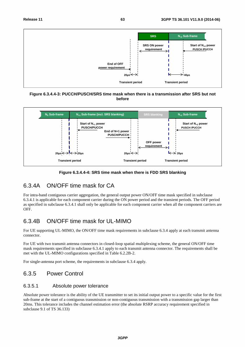
Release 11
3GPP
3GPP TS 36.101 V11.9.0 (2014-06) 63
20µs 40µs
Transient period
PUSCH /PUCCH
Start of N+2 power
power requirement
Transient period
End of OFF
SRS N+2 Sub-frame
SRS ON power
requirement
Figure 6.3.4.4-3: PUCCH/PUSCH/SRS time mask when there is a transmission after SRS but not before
20µs 20µs 20µs 20µs
Transient period
PUSCH /PUCCH
N+2 Sub-frame
End of N+1 power
SRS blanking
PUSCH/PUCCH
Start of N+1 power
N0 Sub-frame
Transient period Transient period
PUSCH/PUCCH
OFF power
N+1 Sub-frame (incl. SRS blanking)
Start of N+2 power
requirement
Figure 6.3.4.4-4: SRS time mask when there is FDD SRS blanking
6.3.4A ON/OFF time mask for CA
For intra-band contiguous carrier aggregation, the general output power ON/OFF time mask specified in subclause
6.3.4.1 is applicable for each component carrier during the ON power period and the transient periods. The OFF period
as specified in subclause 6.3.4.1 shall only be applicable for each component carrier when all the component carriers are
OFF.
6.3.4B ON/OFF time mask for UL-MIMO
For UE supporting UL-MIMO, the ON/OFF time mask requirements in subclause 6.3.4 apply at each transmit antenna
connector.
For UE with two transmit antenna connectors in closed-loop spatial multiplexing scheme, the general ON/OFF time
mask requirements specified in subclause 6.3.4.1 apply to each transmit antenna connector. The requirements shall be
met with the UL-MIMO configurations specified in Table 6.2.2B-2.
For single-antenna port scheme, the requirements in subclause 6.3.4 apply.
6.3.5 Power Control
6.3.5.1 Absolute power tolerance
Absolute power tolerance is the ability of the UE transmitter to set its initial output power to a specific value for the first
sub-frame at the start of a contiguous transmission or non-contiguous transmission with a transmission gap larger than
20ms. This tolerance includes the channel estimation error (the absolute RSRP accuracy requirement specified in
subclause 9.1 of TS 36.133)

Release 11
3GPP
3GPP TS 36.101 V11.9.0 (2014-06) 64
In the case of a PRACH transmission, the absolute tolerance is specified for the first preamble. The absolute power
tolerance includes the channel estimation error (the absolute RSRP accuracy requirement specified in subclause 9.1 of
TS 36.133).
6.3.5.1.1 Minimum requirements
The minimum requirement for absolute power tolerance is given in Table 6.3.5.1.1-1 over the power range bounded by
the Maximum output power as defined in subclause 6.2.2 and the Minimum output power as defined in subclause 6.3.2.
For operating bands under Note 2 in Table 6.2.2-1, the absolute power tolerance as specified in Table 6.3.5.1.1-1 is
relaxed by reducing the lower limit by 1.5 dB when the transmission bandwidth is confined within FUL_low and FUL_low +
4 MHz or FUL_high – 4 MHz and FUL_high.
Table 6.3.5.1.1-1: Absolute power tolerance
Conditions Tolerance
Normal ± 9.0 dB
Extreme ± 12.0 dB
6.3.5.2 Relative Power tolerance
The relative power tolerance is the ability of the UE transmitter to set its output power in a target sub-frame relatively to
the power of the most recently transmitted reference sub-frame if the transmission gap between these sub-frames is ≤ 20
ms.
For PRACH transmission, the relative tolerance is the ability of the UE transmitter to set its output power relatively to
the power of the most recently transmitted preamble. The measurement period for the PRACH preamble is specified in
Table 6.3.4.2-1.
6.3.5.2.1 Minimum requirements
The requirements specified in Table 6.3.5.2.1-1 apply when the power of the target and reference sub-frames are within
the power range bounded by the Minimum output power as defined in subclause 6.3.2 and the measured PUMAX as
defined in subclause 6.2.5 (i.e, the actual power as would be measured assuming no measurement error). This power
shall be within the power limits specified in subclause 6.2.5.
To account for RF Power amplifier mode changes 2 exceptions are allowed for each of two test patterns. The test
patterns are a monotonically increasing power sweep and a monotonically decreasing power sweep over a range
bounded by the requirements of minimum power and maximum power specified in subclauses 6.3.2 and 6.2.2. For these
exceptions the power tolerance limit is a maximum of ±6.0 dB in Table 6.3.5.2.1-1

Release 11
3GPP
3GPP TS 36.101 V11.9.0 (2014-06) 65
Table 6.3.5.2.1-1 Relative power tolerance for transmission (normal conditions)
Power step P (Up or down)
[dB]
All combinations of PUSCH and
PUCCH transitions [dB]
All combinations of PUSCH/PUCCH and
SRS transitions between sub-frames [dB]
PRACH [dB]
ΔP < 2 ±2.5 (Note 3) ±3.0 ±2.5
2 ≤ ΔP < 3 ±3.0 ±4.0 ±3.0
3 ≤ ΔP < 4 ±3.5 ±5.0 ±3.5
4 ≤ ΔP ≤ 10 ±4.0 ±6.0 ±4.0
10 ≤ ΔP < 15 ±5.0 ±8.0 ±5.0
15 ≤ ΔP ±6.0 ±9.0 ±6.0
NOTE 1: For extreme conditions an additional ± 2.0 dB relaxation is allowed NOTE 2: For operating bands under Note 2 in Table 6.2.2-1, the relative power
tolerance is relaxed by increasing the upper limit by 1.5 dB if the transmission bandwidth of the reference sub-frames is confined within FUL_low and FUL_low + 4 MHz or FUL_high – 4 MHz and FUL_high and the target sub-frame is not confined within any one of these frequency ranges; if the transmission bandwidth of the target sub-frame is confined within FUL_low and FUL_low + 4 MHz or FUL_high – 4 MHz and FUL_high and the reference sub-frame is not confined within any one of these frequency ranges, then the tolerance is relaxed by reducing the lower limit by 1.5 dB.
NOTE 3: For PUSCH to PUSCH transitions with the allocated resource blocks fixed in frequency and no transmission gaps other than those generated by downlink subframes, DwPTS fields or Guard Periods for TDD: for a power step ΔP ≤ 1 dB, the relative power tolerance for transmission is ±1.0 dB.
The power step (ΔP) is defined as the difference in the calculated setting of the UE Transmit power between the target
and reference sub-frames with the power setting according to subclause 5.1 of [TS 36.213]. The error is the difference
between ΔP and the power change measured at the UE antenna port with the power of the cell-specific reference signals
kept constant. The error shall be less than the relative power tolerance specified in Table 6.3.5.2.1-1.
For sub-frames not containing an SRS symbol, the power change is defined as the relative power difference between the
mean power of the original reference sub-frame and the mean power of the target subframe not including transient
durations. The mean power of successive sub-frames shall be calculated according to Figure 6.3.4.3-1 and Figure
6.3.4.1-1 if there is a transmission gap between the reference and target sub-frames.
If at least one of the sub-frames contains an SRS symbol, the power change is defined as the relative power difference
between the mean power of the last transmission within the reference sub-frame and the mean power of the first
transmission within the target sub-frame not including transient durations. A transmission is defined as PUSCH,
PUCCH or an SRS symbol. The mean power of the reference and target sub-frames shall be calculated according to
Figures 6.3.4.1-1, 6.3.4.2-1, 6.3.4.4-1, 6.3.4.4-2 and 6.3.4.4-3 for these cases.
6.3.5.3 Aggregate power control tolerance
Aggregate power control tolerance is the ability of a UE to maintain its power in non-contiguous transmission within 21
ms in response to 0 dB TPC commands with respect to the first UE transmission, when the power control parameters
specified in TS 36.213 are constant.
6.3.5.3.1 Minimum requirement
The UE shall meet the requirements specified in Table 6.3.5.3.1-1 for aggregate power control over the power range
bounded by the minimum output power as defined in subclause 6.3.2 and the maximum output power as defined in
subclause 6.2.2.

Release 11
3GPP
3GPP TS 36.101 V11.9.0 (2014-06) 66
Table 6.3.5.3.1-1: Aggregate power control tolerance
TPC command UL channel Aggregate power tolerance within 21 ms
0 dB PUCCH ±2.5 dB
0 dB PUSCH ±3.5 dB
NOTE: The UE transmission gap is 4 ms. TPC command is transmitted via PDCCH 4 subframes preceding each PUCCH/PUSCH transmission.
6.3.5A Power control for CA
The requirements apply for one single PUCCH, PUSCH or SRS transmission of contiguous PRB allocation per
component carrier with power setting in accordance with Clause 5.1 of [6].
6.3.5A.1 Absolute power tolerance
The absolute power tolerance is the ability of the UE transmitter to set its initial output power to a specific value for the
first sub-frame at the start of a contiguous transmission or non-contiguous transmission with a transmission gap on each
active component carriers larger than 20ms. The requirement can be tested by time aligning any transmission gaps on
the component carriers.
6.3.5A.1.1 Minimum requirements
For intra-band contiguous carrier aggregation bandwidth classes B and C the absolute power control tolerance per
component carrier is given in Table 6.3.5.1.1-1.
6.3.5A.2 Relative power tolerance
6.3.5A.2.1 Minimum requirements
The requirements apply when the power of the target and reference sub-frames on each component carrier exceed -20
dBm and the total power is limited by PUMAX as defined in subclause 6.2.5A. For the purpose of these requirements, the
power in each component carrier is specified over only the transmitted resource blocks.
For intra-band contiguous carrier aggregation bandwidth classes B and C, the UE shall meet the following requirements
for transmission on both assigned component carriers when the average transmit power per PRB is aligned across both
assigned carriers in the reference sub-frame:
a) for all possible combinations of PUSCH and PUCCH transitions per component carrier, the corresponding
requirements given in Table 6.3.5.2.1-1:
b) for SRS transitions on each component carrier, the requirements for combinations of PUSCH/PUCCH and SRS
transitions given in Table 6.3.5.2.1-1 with simultaneous SRS of constant SRS bandwidth allocated in the target and
reference subrames:
c) for RACH on the primary component carrier, the requirements given in Table 6.3.5.2.1-1 for PRACH
For a) and b) above, the power step P between the reference and target subframes shall be set by a TPC command
and/or an uplink scheduling grant transmitted by means of an appropriate DCI Format.
For a), b) and c) above, two exceptions are allowed for each component carrier for a power per carrier ranging from -20
dBm to PUMAX,c as defined in subclause 6.2.5. For these exceptions the power tolerance limit is ±6.0 dB in Table
6.3.5.2.1-1..
6.3.5A.3 Aggregate power control tolerance
Aggregate power control tolerance is the ability of a UE to maintain its power in non-contiguous transmission within 21
ms in response to 0 dB TPC commands with respect to the first UE transmission, when the power control parameters
specified in [6] are constant on all active component carriers.
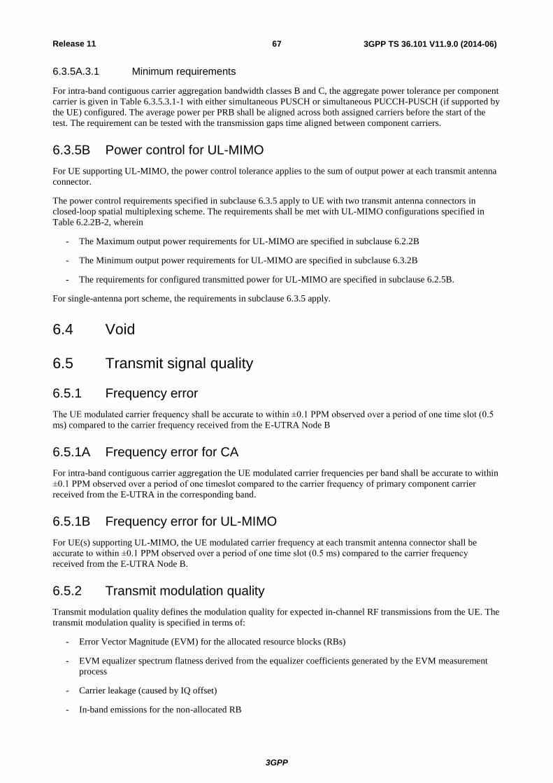
Release 11
3GPP
3GPP TS 36.101 V11.9.0 (2014-06) 67
6.3.5A.3.1 Minimum requirements
For intra-band contiguous carrier aggregation bandwidth classes B and C, the aggregate power tolerance per component
carrier is given in Table 6.3.5.3.1-1 with either simultaneous PUSCH or simultaneous PUCCH-PUSCH (if supported by
the UE) configured. The average power per PRB shall be aligned across both assigned carriers before the start of the
test. The requirement can be tested with the transmission gaps time aligned between component carriers.
6.3.5B Power control for UL-MIMO
For UE supporting UL-MIMO, the power control tolerance applies to the sum of output power at each transmit antenna
connector.
The power control requirements specified in subclause 6.3.5 apply to UE with two transmit antenna connectors in
closed-loop spatial multiplexing scheme. The requirements shall be met with UL-MIMO configurations specified in
Table 6.2.2B-2, wherein
- The Maximum output power requirements for UL-MIMO are specified in subclause 6.2.2B
- The Minimum output power requirements for UL-MIMO are specified in subclause 6.3.2B
- The requirements for configured transmitted power for UL-MIMO are specified in subclause 6.2.5B.
For single-antenna port scheme, the requirements in subclause 6.3.5 apply.
6.4 Void
6.5 Transmit signal quality
6.5.1 Frequency error
The UE modulated carrier frequency shall be accurate to within ±0.1 PPM observed over a period of one time slot (0.5
ms) compared to the carrier frequency received from the E-UTRA Node B
6.5.1A Frequency error for CA
For intra-band contiguous carrier aggregation the UE modulated carrier frequencies per band shall be accurate to within
±0.1 PPM observed over a period of one timeslot compared to the carrier frequency of primary component carrier
received from the E-UTRA in the corresponding band.
6.5.1B Frequency error for UL-MIMO
For UE(s) supporting UL-MIMO, the UE modulated carrier frequency at each transmit antenna connector shall be
accurate to within ±0.1 PPM observed over a period of one time slot (0.5 ms) compared to the carrier frequency
received from the E-UTRA Node B.
6.5.2 Transmit modulation quality
Transmit modulation quality defines the modulation quality for expected in-channel RF transmissions from the UE. The
transmit modulation quality is specified in terms of:
- Error Vector Magnitude (EVM) for the allocated resource blocks (RBs)
- EVM equalizer spectrum flatness derived from the equalizer coefficients generated by the EVM measurement
process
- Carrier leakage (caused by IQ offset)
- In-band emissions for the non-allocated RB

Release 11
3GPP
3GPP TS 36.101 V11.9.0 (2014-06) 68
All the parameters defined in subclause 6.5.2 are defined using the measurement methodology specified in Annex F.
6.5.2.1 Error Vector Magnitude
The Error Vector Magnitude is a measure of the difference between the reference waveform and the measured
waveform. This difference is called the error vector. Before calculating the EVM the measured waveform is corrected
by the sample timing offset and RF frequency offset. Then the IQ origin offset shall be removed from the measured
waveform before calculating the EVM.
The measured waveform is further modified by selecting the absolute phase and absolute amplitude of the Tx chain.
The EVM result is defined after the front-end IDFT as the square root of the ratio of the mean error vector power to the
mean reference power expressed as a %.
The basic EVM measurement interval in the time domain is one preamble sequence for the PRACH and is one slot for
the PUCCH and PUSCH in the time domain.. When the PUSCH or PUCCH transmission slot is shortened due to
multiplexing with SRS, the EVM measurement interval is reduced by one symbol, accordingly. The PUSCH or PUCCH
EVM measurement interval is also reduced when the mean power, modulation or allocation between slots is expected to
change. In the case of PUSCH transmission, the measurement interval is reduced by a time interval equal to the sum of
5 μs and the applicable exclusion period defined in subclause 6.3.4, adjacent to the boundary where the power change is
expected to occur. The PUSCH exclusion period is applied to the signal obtained after the front-end IDFT. In the case
of PUCCH transmission with power change, the PUCCH EVM measurement interval is reduced by one symbol
adjacent to the boundary where the power change is expected to occur.
6.5.2.1.1 Minimum requirement
The RMS average of the basic EVM measurements for 10 sub-frames excluding any transient period for the average
EVM case, and 60 sub-frames excluding any transient period for the reference signal EVM case, for the different
modulations schemes shall not exceed the values specified in Table 6.5.2.1.1-1 for the parameters defined in Table
6.5.2.1.1-2. For EVM evaluation purposes, [all PRACH preamble formats 0-4 and] all PUCCH formats 1, 1a, 1b, 2, 2a
and 2b are considered to have the same EVM requirement as QPSK modulated.
Table 6.5.2.1.1-1: Minimum requirements for Error Vector Magnitude
Parameter Unit Average EVM Level Reference Signal EVM Level
QPSK or BPSK % 17.5 17.5
16QAM % 12.5 12.5
Table 6.5.2.1.1-2: Parameters for Error Vector Magnitude
Parameter Unit Level
UE Output Power dBm -40
Operating conditions Normal conditions
6.5.2.2 Carrier leakage
Carrier leakage (The IQ origin offset) is an additive sinusoid waveform that has the same frequency as the modulated
waveform carrier frequency. The measurement interval is one slot in the time domain.
6.5.2.2.1 Minimum requirements
The relative carrier leakage power is a power ratio of the additive sinusoid waveform and the modulated waveform. The
relative carrier leakage power shall not exceed the values specified in Table 6.5.2.2.1-1.
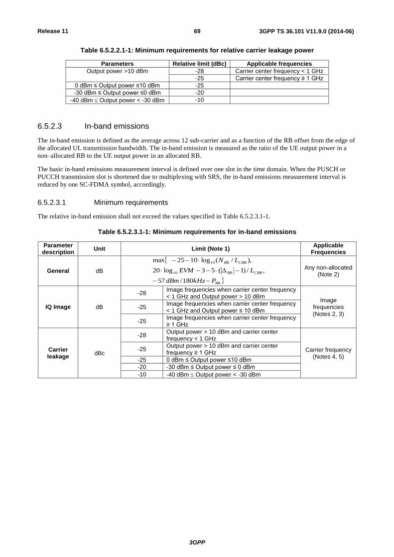
Release 11
3GPP
3GPP TS 36.101 V11.9.0 (2014-06) 69
Table 6.5.2.2.1-1: Minimum requirements for relative carrier leakage power
Parameters Relative limit (dBc) Applicable frequencies
Output power >10 dBm -28 Carrier center frequency < 1 GHz
-25 Carrier center frequency ≥ 1 GHz
0 dBm ≤ Output power ≤10 dBm -25
-30 dBm ≤ Output power ≤0 dBm -20
-40 dBm Output power < -30 dBm -10
6.5.2.3 In-band emissions
The in-band emission is defined as the average across 12 sub-carrier and as a function of the RB offset from the edge of
the allocated UL transmission bandwidth. The in-band emission is measured as the ratio of the UE output power in a
non–allocated RB to the UE output power in an allocated RB.
The basic in-band emissions measurement interval is defined over one slot in the time domain. When the PUSCH or
PUCCH transmission slot is shortened due to multiplexing with SRS, the in-band emissions measurement interval is
reduced by one SC-FDMA symbol, accordingly.
6.5.2.3.1 Minimum requirements
The relative in-band emission shall not exceed the values specified in Table 6.5.2.3.1-1.
Table 6.5.2.3.1-1: Minimum requirements for in-band emissions
Parameter description
Unit Limit (Note 1) Applicable
Frequencies
General dB
RB
CRBRB
CRBRB
PkHzdBm
LEVM
LN
180/57
,/)1(53log20
),/(log1025max
10
10
Any non-allocated (Note 2)
IQ Image dB
-28 Image frequencies when carrier center frequency < 1 GHz and Output power > 10 dBm
Image frequencies (Notes 2, 3)
-25 Image frequencies when carrier center frequency < 1 GHz and Output power ≤ 10 dBm
-25 Image frequencies when carrier center frequency ≥ 1 GHz
Carrier leakage
dBc
-28 Output power > 10 dBm and carrier center frequency < 1 GHz
Carrier frequency (Notes 4, 5)
-25 Output power > 10 dBm and carrier center frequency ≥ 1 GHz
-25 0 dBm ≤ Output power ≤10 dBm
-20 -30 dBm ≤ Output power ≤ 0 dBm
-10 -40 dBm Output power < -30 dBm
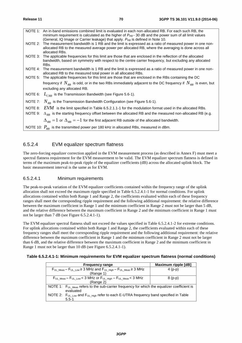
Release 11
3GPP
3GPP TS 36.101 V11.9.0 (2014-06) 70
NOTE 1: An in-band emissions combined limit is evaluated in each non-allocated RB. For each such RB, the minimum requirement is calculated as the higher of PRB - 30 dB and the power sum of all limit values (General, IQ Image or Carrier leakage) that apply. PRB is defined in Note 10.
NOTE 2: The measurement bandwidth is 1 RB and the limit is expressed as a ratio of measured power in one non-allocated RB to the measured average power per allocated RB, where the averaging is done across all allocated RBs.
NOTE 3: The applicable frequencies for this limit are those that are enclosed in the reflection of the allocated bandwidth, based on symmetry with respect to the centre carrier frequency, but excluding any allocated RBs.
NOTE 4: The measurement bandwidth is 1 RB and the limit is expressed as a ratio of measured power in one non-allocated RB to the measured total power in all allocated RBs.
NOTE 5: The applicable frequencies for this limit are those that are enclosed in the RBs containing the DC
frequency if RBN is odd, or in the two RBs immediately adjacent to the DC frequency if RBN is even, but
excluding any allocated RB.
NOTE 6: CRBL is the Transmission Bandwidth (see Figure 5.6-1).
NOTE 7: RBN is the Transmission Bandwidth Configuration (see Figure 5.6-1).
NOTE 8: EVM is the limit specified in Table 6.5.2.1.1-1 for the modulation format used in the allocated RBs.
NOTE 9: RB is the starting frequency offset between the allocated RB and the measured non-allocated RB (e.g.
1RB or 1RB for the first adjacent RB outside of the allocated bandwidth.
NOTE 10: RBP is the transmitted power per 180 kHz in allocated RBs, measured in dBm.
6.5.2.4 EVM equalizer spectrum flatness
The zero-forcing equalizer correction applied in the EVM measurement process (as described in Annex F) must meet a
spectral flatness requirement for the EVM measurement to be valid. The EVM equalizer spectrum flatness is defined in
terms of the maximum peak-to-peak ripple of the equalizer coefficients (dB) across the allocated uplink block. The
basic measurement interval is the same as for EVM.
6.5.2.4.1 Minimum requirements
The peak-to-peak variation of the EVM equalizer coefficients contained within the frequency range of the uplink
allocation shall not exceed the maximum ripple specified in Table 6.5.2.4.1-1 for normal conditions. For uplink
allocations contained within both Range 1 and Range 2, the coefficients evaluated within each of these frequency
ranges shall meet the corresponding ripple requirement and the following additional requirement: the relative difference
between the maximum coefficient in Range 1 and the minimum coefficient in Range 2 must not be larger than 5 dB,
and the relative difference between the maximum coefficient in Range 2 and the minimum coefficient in Range 1 must
not be larger than 7 dB (see Figure 6.5.2.4.1-1).
The EVM equalizer spectral flatness shall not exceed the values specified in Table 6.5.2.4.1-2 for extreme conditions.
For uplink allocations contained within both Range 1 and Range 2, the coefficients evaluated within each of these
frequency ranges shall meet the corresponding ripple requirement and the following additional requirement: the relative
difference between the maximum coefficient in Range 1 and the minimum coefficient in Range 2 must not be larger
than 6 dB, and the relative difference between the maximum coefficient in Range 2 and the minimum coefficient in
Range 1 must not be larger than 10 dB (see Figure 6.5.2.4.1-1).
Table 6.5.2.4.1-1: Minimum requirements for EVM equalizer spectrum flatness (normal conditions)
Frequency range Maximum ripple [dB]
FUL_Meas – FUL_Low ≥ 3 MHz and FUL_High – FUL_Meas ≥ 3 MHz (Range 1)
4 (p-p)
FUL_Meas – FUL_Low < 3 MHz or FUL_High – FUL_Meas < 3 MHz (Range 2)
8 (p-p)
NOTE 1: FUL_Meas refers to the sub-carrier frequency for which the equalizer coefficient is evaluated
NOTE 2: FUL_Low and FUL_High refer to each E-UTRA frequency band specified in Table 5.5-1

Release 11
3GPP
3GPP TS 36.101 V11.9.0 (2014-06) 71
Table 6.5.2.4.1-2: Minimum requirements for EVM equalizer spectrum flatness (extreme conditions)
Frequency range Maximum Ripple [dB]
FUL_Meas – FUL_Low ≥ 5 MHz and FUL_High – FUL_Meas ≥ 5 MHz (Range 1)
4 (p-p)
FUL_Meas – FUL_Low < 5 MHz or FUL_High – FUL_Meas < 5 MHz (Range 2)
12 (p-p)
NOTE 1: FUL_Meas refers to the sub-carrier frequency for which the equalizer coefficient is evaluated
NOTE 2: FUL_Low and FUL_High refer to each E-UTRA frequency band specified in Table 5.5-1
Figure 6.5.2.4.1-1: The limits for EVM equalizer spectral flatness with the maximum allowed variation of the coefficients indicated (the ETC minimum requirement within brackets).
6.5.2A Transmit modulation quality for CA
The requirements in this clause apply with PCC and SCC in the UL configured and activated: PCC with PRB allocation
and SCC without PRB allocation and without CSI reporting and SRS configured.
6.5.2A.1 Error Vector Magnitude
For the intra-band contiguous carrier aggregation, the Error Vector Magnitude requirement should be defined for each
component carrier. Requirements only apply with PRB allocation in one of the component carriers.
When a single component carrier is configured Table 6.5.2.1.1-1 apply.
The EVM requirements are according to Table 6.5.2A.1-1 if CA is configured in uplink.
Table 6.5.2A.1-1: Minimum requirements for Error Vector Magnitude
Parameter Unit Average EVM Level per CC
Reference Signal EVM Level
QPSK or BPSK % 17.5 17.5
16QAM % 12.5 12.5
6.5.2A.2 Carrier leakage for CA
Carrier leakage (The IQ origin offset) is an additive sinusoid waveform that has the same frequency as the modulated
waveform carrier frequency. Carrier leakage is defined for each component carrier and is measured on the carrier with
PRBs allocated. The measurement interval is one slot in the time domain.
f FUL_High FUL_High – 3(5) MHz
< 4(4) dBp-p
Range 1 Range 2
max(Range 1)-min(Range 2) < 5(6) dB max(Range 2)-min(Range 1) < 7(10) dB < 8(12) dBp-p
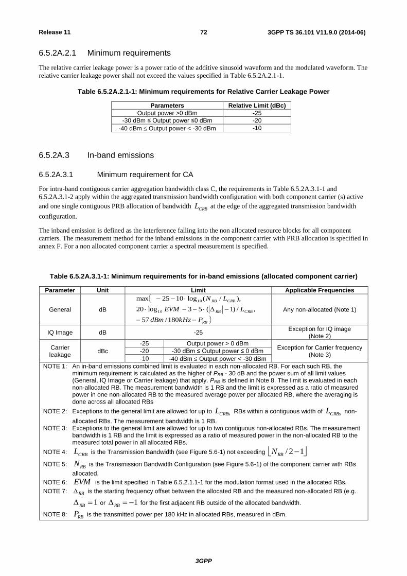
Release 11
3GPP
3GPP TS 36.101 V11.9.0 (2014-06) 72
6.5.2A.2.1 Minimum requirements
The relative carrier leakage power is a power ratio of the additive sinusoid waveform and the modulated waveform. The
relative carrier leakage power shall not exceed the values specified in Table 6.5.2A.2.1-1.
Table 6.5.2A.2.1-1: Minimum requirements for Relative Carrier Leakage Power
Parameters Relative Limit (dBc)
Output power >0 dBm -25
-30 dBm ≤ Output power ≤0 dBm -20
-40 dBm Output power < -30 dBm -10
6.5.2A.3 In-band emissions
6.5.2A.3.1 Minimum requirement for CA
For intra-band contiguous carrier aggregation bandwidth class C, the requirements in Table 6.5.2A.3.1-1 and
6.5.2A.3.1-2 apply within the aggregated transmission bandwidth configuration with both component carrier (s) active
and one single contiguous PRB allocation of bandwidth CRBL at the edge of the aggregated transmission bandwidth
configuration.
The inband emission is defined as the interference falling into the non allocated resource blocks for all component
carriers. The measurement method for the inband emissions in the component carrier with PRB allocation is specified in
annex F. For a non allocated component carrier a spectral measurement is specified.
Table 6.5.2A.3.1-1: Minimum requirements for in-band emissions (allocated component carrier)
Parameter Unit Limit Applicable Frequencies
General dB
RB
CRBRB
CRBRB
PkHzdBm
LEVM
LN
180/57
,/)1(53log20
),/(log1025max
10
10
Any non-allocated (Note 1)
IQ Image dB -25 Exception for IQ image
(Note 2)
Carrier leakage
dBc
-25 Output power > 0 dBm Exception for Carrier frequency
(Note 3) -20 -30 dBm ≤ Output power ≤ 0 dBm
-10 -40 dBm Output power < -30 dBm
NOTE 1: An in-band emissions combined limit is evaluated in each non-allocated RB. For each such RB, the minimum requirement is calculated as the higher of PRB - 30 dB and the power sum of all limit values (General, IQ Image or Carrier leakage) that apply. PRB is defined in Note 8. The limit is evaluated in each non-allocated RB. The measurement bandwidth is 1 RB and the limit is expressed as a ratio of measured power in one non-allocated RB to the measured average power per allocated RB, where the averaging is done across all allocated RBs
NOTE 2: Exceptions to the general limit are allowed for up to CRBsL RBs within a contiguous width of CRBsL non-
allocated RBs. The measurement bandwidth is 1 RB. NOTE 3: Exceptions to the general limit are allowed for up to two contiguous non-allocated RBs. The measurement
bandwidth is 1 RB and the limit is expressed as a ratio of measured power in the non-allocated RB to the measured total power in all allocated RBs.
NOTE 4: CRBL is the Transmission Bandwidth (see Figure 5.6-1) not exceeding 12/ RBN
NOTE 5: RBN is the Transmission Bandwidth Configuration (see Figure 5.6-1) of the component carrier with RBs
allocated.
NOTE 6: EVM is the limit specified in Table 6.5.2.1.1-1 for the modulation format used in the allocated RBs.
NOTE 7: RB is the starting frequency offset between the allocated RB and the measured non-allocated RB (e.g.
1RB or 1RB for the first adjacent RB outside of the allocated bandwidth.
NOTE 8: RBP is the transmitted power per 180 kHz in allocated RBs, measured in dBm.
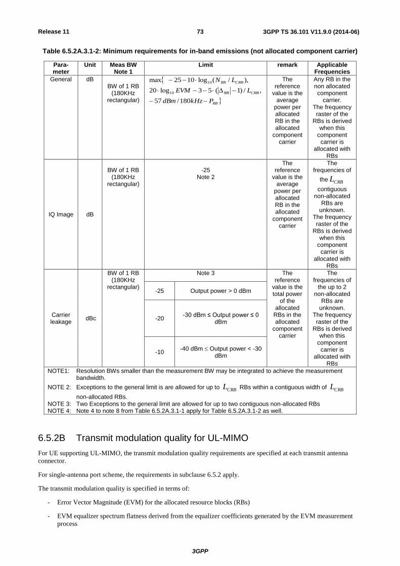
Release 11
3GPP
3GPP TS 36.101 V11.9.0 (2014-06) 73
Table 6.5.2A.3.1-2: Minimum requirements for in-band emissions (not allocated component carrier)
Para-meter
Unit Meas BW Note 1
Limit remark Applicable Frequencies
General dB BW of 1 RB
(180KHz rectangular)
RB
CRBRB
CRBRB
PkHzdBm
LEVM
LN
180/57
,/)1(53log20
),/(log1025max
10
10
The reference
value is the average
power per allocated RB in the allocated
component carrier
Any RB in the non allocated component
carrier. The frequency raster of the
RBs is derived when this
component carrier is
allocated with RBs
IQ Image dB
BW of 1 RB
(180KHz rectangular)
-25
Note 2
The reference
value is the average
power per allocated RB in the allocated
component carrier
The frequencies of
the CRBL
contiguous non-allocated
RBs are unknown.
The frequency raster of the
RBs is derived when this
component carrier is
allocated with RBs
Carrier leakage
dBc
BW of 1 RB (180KHz
rectangular)
Note 3 The reference
value is the total power
of the allocated
RBs in the allocated
component carrier
The frequencies of
the up to 2 non-allocated
RBs are unknown.
The frequency raster of the
RBs is derived when this
component carrier is
allocated with RBs
-25 Output power > 0 dBm
-20 -30 dBm ≤ Output power ≤ 0
dBm
-10 -40 dBm Output power < -30
dBm
NOTE1: Resolution BWs smaller than the measurement BW may be integrated to achieve the measurement bandwidth.
NOTE 2: Exceptions to the general limit is are allowed for up to CRBL RBs within a contiguous width of CRBL
non-allocated RBs. NOTE 3: Two Exceptions to the general limit are allowed for up to two contiguous non-allocated RBs NOTE 4: Note 4 to note 8 from Table 6.5.2A.3.1-1 apply for Table 6.5.2A.3.1-2 as well.
6.5.2B Transmit modulation quality for UL-MIMO
For UE supporting UL-MIMO, the transmit modulation quality requirements are specified at each transmit antenna
connector.
For single-antenna port scheme, the requirements in subclause 6.5.2 apply.
The transmit modulation quality is specified in terms of:
- Error Vector Magnitude (EVM) for the allocated resource blocks (RBs)
- EVM equalizer spectrum flatness derived from the equalizer coefficients generated by the EVM measurement
process

Release 11
3GPP
3GPP TS 36.101 V11.9.0 (2014-06) 74
- Carrier leakage (caused by IQ offset)
- In-band emissions for the non-allocated RB
6.5.2B.1 Error Vector Magnitude
For UE with two transmit antenna connectors in closed-loop spatial multiplexing scheme, the Error Vector Magnitude
requirements specified in Table 6.5.2.1.1-1 which is defined in subclause 6.5.2.1 apply at each transmit antenna
connector. The requirements shall be met with the UL-MIMO configurations specified in Table 6.2.2B-2.
6.5.2B.2 Carrier leakage
For UE with two transmit antenna connectors in closed-loop spatial multiplexing scheme, the Relative Carrier Leakage
Power requirements specified in Table 6.5.2.2.1-1 which is defined in subclause 6.5.2.2 apply at each transmit antenna
connector. The requirements shall be met with the UL-MIMO configurations specified in Table 6.2.2B-2.
6.5.2B.3 In-band emissions
For UE with two transmit antenna connectors in closed-loop spatial multiplexing scheme, the In-band Emission
requirements specified in Table 6.5.2.3.1-1 which is defined in subclause 6.5.2.3 apply at each transmit antenna
connector. The requirements shall be met with the uplink MIMO configurations specified in Table 6.2.2B-2.
6.5.2B.4 EVM equalizer spectrum flatness for UL-MIMO
For UE with two transmit antenna connectors in closed-loop spatial multiplexing scheme, the EVM Equalizer Spectrum
Flatness requirements specified in Table 6.5.2.4.1-1 and Table 6.5.2.4.1-2 which are defined in subclause 6.5.2.4 apply
at each transmit antenna connector. The requirements shall be met with the UL-MIMO configurations specified in Table
6.2.2B-2.
6.6 Output RF spectrum emissions
The output UE transmitter spectrum consists of the three components; the emission within the occupied bandwidth
(channel bandwidth), the Out Of Band (OOB) emissions and the far out spurious emission domain.
Figure 6.6-1: Transmitter RF spectrum
6.6.1 Occupied bandwidth
Occupied bandwidth is defined as the bandwidth containing 99 % of the total integrated mean power of the transmitted
spectrum on the assigned channel. The occupied bandwidth for all transmission bandwidth configurations (Resources
Blocks) shall be less than the channel bandwidth specified in Table 6.6.1-1
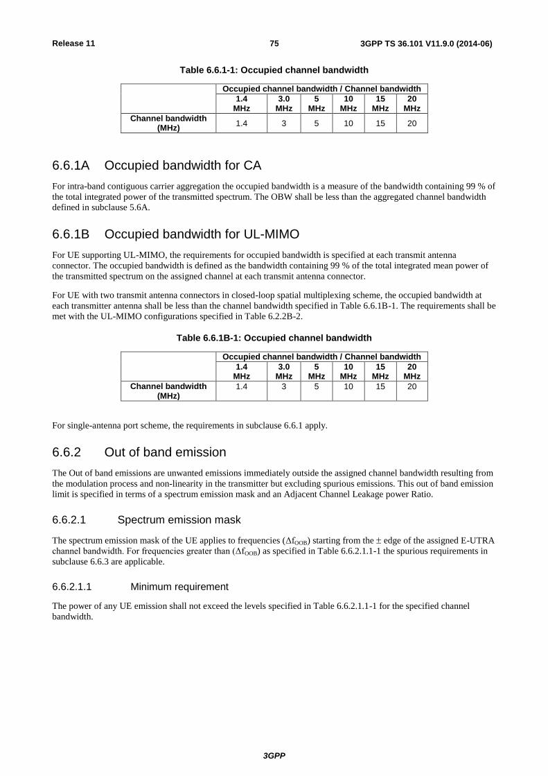
Release 11
3GPP
3GPP TS 36.101 V11.9.0 (2014-06) 75
Table 6.6.1-1: Occupied channel bandwidth
Occupied channel bandwidth / Channel bandwidth
1.4 MHz
3.0 MHz
5 MHz
10 MHz
15 MHz
20 MHz
Channel bandwidth (MHz)
1.4 3 5 10 15 20
6.6.1A Occupied bandwidth for CA
For intra-band contiguous carrier aggregation the occupied bandwidth is a measure of the bandwidth containing 99 % of
the total integrated power of the transmitted spectrum. The OBW shall be less than the aggregated channel bandwidth
defined in subclause 5.6A.
6.6.1B Occupied bandwidth for UL-MIMO
For UE supporting UL-MIMO, the requirements for occupied bandwidth is specified at each transmit antenna
connector. The occupied bandwidth is defined as the bandwidth containing 99 % of the total integrated mean power of
the transmitted spectrum on the assigned channel at each transmit antenna connector.
For UE with two transmit antenna connectors in closed-loop spatial multiplexing scheme, the occupied bandwidth at
each transmitter antenna shall be less than the channel bandwidth specified in Table 6.6.1B-1. The requirements shall be
met with the UL-MIMO configurations specified in Table 6.2.2B-2.
Table 6.6.1B-1: Occupied channel bandwidth
Occupied channel bandwidth / Channel bandwidth
1.4 MHz
3.0 MHz
5 MHz
10 MHz
15 MHz
20 MHz
Channel bandwidth (MHz)
1.4 3 5 10 15 20
For single-antenna port scheme, the requirements in subclause 6.6.1 apply.
6.6.2 Out of band emission
The Out of band emissions are unwanted emissions immediately outside the assigned channel bandwidth resulting from
the modulation process and non-linearity in the transmitter but excluding spurious emissions. This out of band emission
limit is specified in terms of a spectrum emission mask and an Adjacent Channel Leakage power Ratio.
6.6.2.1 Spectrum emission mask
The spectrum emission mask of the UE applies to frequencies (ΔfOOB) starting from the edge of the assigned E-UTRA
channel bandwidth. For frequencies greater than (ΔfOOB) as specified in Table 6.6.2.1.1-1 the spurious requirements in
subclause 6.6.3 are applicable.
6.6.2.1.1 Minimum requirement
The power of any UE emission shall not exceed the levels specified in Table 6.6.2.1.1-1 for the specified channel
bandwidth.
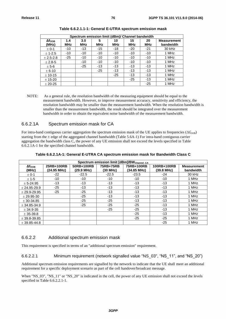
Release 11
3GPP
3GPP TS 36.101 V11.9.0 (2014-06) 76
Table 6.6.2.1.1-1: General E-UTRA spectrum emission mask
Spectrum emission limit (dBm)/ Channel bandwidth
ΔfOOB (MHz)
1.4 MHz
3.0 MHz
5 MHz
10 MHz
15 MHz
20 MHz
Measurement bandwidth
0-1 -10 -13 -15 -18 -20 -21 30 kHz
1-2.5 -10 -10 -10 -10 -10 -10 1 MHz
2.5-2.8 -25 -10 -10 -10 -10 -10 1 MHz
2.8-5 -10 -10 -10 -10 -10 1 MHz
5-6 -25 -13 -13 -13 -13 1 MHz
6-10 -25 -13 -13 -13 1 MHz
10-15 -25 -13 -13 1 MHz
15-20 -25 -13 1 MHz
20-25 -25 1 MHz
NOTE: As a general rule, the resolution bandwidth of the measuring equipment should be equal to the
measurement bandwidth. However, to improve measurement accuracy, sensitivity and efficiency, the
resolution bandwidth may be smaller than the measurement bandwidth. When the resolution bandwidth is
smaller than the measurement bandwidth, the result should be integrated over the measurement
bandwidth in order to obtain the equivalent noise bandwidth of the measurement bandwidth.
6.6.2.1A Spectrum emission mask for CA
For intra-band contiguous carrier aggregation the spectrum emission mask of the UE applies to frequencies (ΔfOOB)
starting from the edge of the aggregated channel bandwidth (Table 5.6A-1) For intra-band contiguous carrier
aggregation the bandwidth class C, the power of any UE emission shall not exceed the levels specified in Table
6.6.2.1A-1 for the specified channel bandwidth.
Table 6.6.2.1A-1: General E-UTRA CA spectrum emission mask for Bandwidth Class C
Spectrum emission limit [dBm]/BWChannel_CA
ΔfOOB (MHz)
25RB+100RB (24.95 MHz)
50RB+100RB (29.9 MHz)
75RB+75RB (30 MHz)
75RB+100RB (34.85 MHz)
100RB+100RB (39.8 MHz)
Measurement bandwidth
0-1 -22 -22.5 -22.5 -23.5 -24 30 kHz
1-5 -10 -10 -10 -10 -10 1 MHz
5-24.95 -13 -13 -13 -13 -13 1 MHz
24.95-29.9 -25 -13 -13 -13 -13 1 MHz
29.9-29.95 -25 -25 -13 -13 -13 1 MHz
29.95-30 -25 -13 -13 -13 1 MHz
30-34.85 -25 -25 -13 -13 1 MHz
34.85-34.9 -25 -25 -25 -13 1 MHz
34.9-35 -25 -25 -13 1 MHz
35-39.8 -25 -13 1 MHz
39.8-39.85 -25 -25 1 MHz
39.85-44.8 -25 1 MHz
6.6.2.2 Additional spectrum emission mask
This requirement is specified in terms of an "additional spectrum emission" requirement.
6.6.2.2.1 Minimum requirement (network signalled value "NS_03", “NS_11”, and “NS_20”)
Additional spectrum emission requirements are signalled by the network to indicate that the UE shall meet an additional
requirement for a specific deployment scenario as part of the cell handover/broadcast message.
When "NS_03", "NS_11" or "NS_20" is indicated in the cell, the power of any UE emission shall not exceed the levels
specified in Table 6.6.2.2.1-1.

Release 11
3GPP
3GPP TS 36.101 V11.9.0 (2014-06) 77
Table 6.6.2.2.1-1: Additional requirements
Spectrum emission limit (dBm)/ Channel bandwidth
ΔfOOB (MHz)
1.4 MHz
3.0 MHz
5 MHz
10 MHz
15 MHz
20 MHz
Measurement bandwidth
0-1 -10 -13 -15 -18 -20 -21 30 kHz
1-2.5 -13 -13 -13 -13 -13 -13 1 MHz
2.5-2.8 -25 -13 -13 -13 -13 -13 1 MHz
2.8-5 -13 -13 -13 -13 -13 1 MHz
5-6 -25 -13 -13 -13 -13 1 MHz
6-10 -25 -13 -13 -13 1 MHz
10-15 -25 -13 -13 1 MHz
15-20 -25 -13 1 MHz
20-25 -25 1 MHz
NOTE: As a general rule, the resolution bandwidth of the measuring equipment should be equal to the
measurement bandwidth. However, to improve measurement accuracy, sensitivity and efficiency, the
resolution bandwidth may be smaller than the measurement bandwidth. When the resolution bandwidth is
smaller than the measurement bandwidth, the result should be integrated over the measurement
bandwidth in order to obtain the equivalent noise bandwidth of the measurement bandwidth.
6.6.2.2.2 Minimum requirement (network signalled value "NS_04")
Additional spectrum emission requirements are signalled by the network to indicate that the UE shall meet an additional
requirement for a specific deployment scenario as part of the cell handover/broadcast message.
When "NS_04" is indicated in the cell, the power of any UE emission shall not exceed the levels specified in Table
6.6.2.2.2-1.
Table 6.6.2.2.2-1: Additional requirements
Spectrum emission limit (dBm)/ Channel bandwidth
ΔfOOB (MHz)
1.4 MHz
3.0 MHz
5 MHz
10 MHz
15 MHz
20 MHz
Measurement bandwidth
0-1 -10 -13 -15 -18 -20 -21 30 kHz
1-2.5 -13 -13 -13 -13 -13 -13 1 MHz
2.5-2.8 -25 -13 -13 -13 -13 -13 1 MHz
2.8-5.5 -13 -13 -13 -13 -13 1 MHz
5.5-6 -25 -25 -25 -25 -25 1 MHz
6-10 -25 -25 -25 -25 1 MHz
10-15 -25 -25 -25 1 MHz
15-20 -25 -25 1 MHz
20-25 -25 1 MHz
Note: As a general rule, the resolution bandwidth of the measuring equipment should be equal to the
measurement bandwidth. However, to improve measurement accuracy, sensitivity and efficiency, the
resolution bandwidth may be smaller than the measurement bandwidth. When the resolution bandwidth is
smaller than the measurement bandwidth, the result should be integrated over the measurement
bandwidth in order to obtain the equivalent noise bandwidth of the measurement bandwidth.
6.6.2.2.3 Minimum requirement (network signalled value "NS_06" or “NS_07”)
Additional spectrum emission requirements are signalled by the network to indicate that the UE shall meet an additional
requirement for a specific deployment scenario as part of the cell handover/broadcast message.
When "NS_06" or “NS_07” is indicated in the cell, the power of any UE emission shall not exceed the levels specified
in Table 6.6.2.2.3-1.
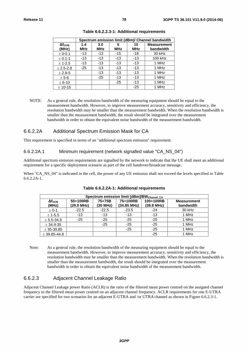
Release 11
3GPP
3GPP TS 36.101 V11.9.0 (2014-06) 78
Table 6.6.2.2.3-1: Additional requirements
Spectrum emission limit (dBm)/ Channel bandwidth
ΔfOOB (MHz)
1.4 MHz
3.0 MHz
5 MHz
10 MHz
Measurement bandwidth
0-0.1 -13 -13 -15 -18 30 kHz
0.1-1 -13 -13 -13 -13 100 kHz
1-2.5 -13 -13 -13 -13 1 MHz
2.5-2.8 -25 -13 -13 -13 1 MHz
2.8-5 -13 -13 -13 1 MHz
5-6 -25 -13 -13 1 MHz
6-10 -25 -13 1 MHz
10-15 -25 1 MHz
NOTE: As a general rule, the resolution bandwidth of the measuring equipment should be equal to the
measurement bandwidth. However, to improve measurement accuracy, sensitivity and efficiency, the
resolution bandwidth may be smaller than the measurement bandwidth. When the resolution bandwidth is
smaller than the measurement bandwidth, the result should be integrated over the measurement
bandwidth in order to obtain the equivalent noise bandwidth of the measurement bandwidth.
6.6.2.2A Additional Spectrum Emission Mask for CA
This requirement is specified in terms of an "additional spectrum emission" requirement.
6.6.2.2A.1 Minimum requirement (network signalled value "CA_NS_04")
Additional spectrum emission requirements are signalled by the network to indicate that the UE shall meet an additional
requirement for a specific deployment scenario as part of the cell handover/broadcast message.
When "CA_NS_04" is indicated in the cell, the power of any UE emission shall not exceed the levels specified in Table
6.6.2.2A-1.
Table 6.6.2.2A-1: Additional requirements
Spectrum emission limit [dBm]/BWChannel_CA
ΔfOOB (MHz)
50+100RB (29.9 MHz)
75+75B (30 MHz)
75+100RB (34.85 MHz)
100+100RB (39.8 MHz)
Measurement bandwidth
0-1 -22.5 -22.5 -23.5 -24 30 kHz
1-5.5 -13 -13 -13 -13 1 MHz
5.5-34.9 -25 -25 -25 -25 1 MHz
34.9-35 -25 -25 -25 1 MHz
35-39.85 -25 -25 1 MHz
39.85-44.8 -25 1 MHz
Note: As a general rule, the resolution bandwidth of the measuring equipment should be equal to the
measurement bandwidth. However, to improve measurement accuracy, sensitivity and efficiency, the
resolution bandwidth may be smaller than the measurement bandwidth. When the resolution bandwidth is
smaller than the measurement bandwidth, the result should be integrated over the measurement
bandwidth in order to obtain the equivalent noise bandwidth of the measurement bandwidth.
6.6.2.3 Adjacent Channel Leakage Ratio
Adjacent Channel Leakage power Ratio (ACLR) is the ratio of the filtered mean power centred on the assigned channel
frequency to the filtered mean power centred on an adjacent channel frequency. ACLR requirements for one E-UTRA
carrier are specified for two scenarios for an adjacent E-UTRA and /or UTRA channel as shown in Figure 6.6.2.3-1.

Release 11
3GPP
3GPP TS 36.101 V11.9.0 (2014-06) 79
E-UTRAACLR1 UTRA ACLR2 UTRAACLR1
RB
E-UTRA channel
Channel
ΔfOOB
Figure 6.6.2.3-1: Adjacent Channel Leakage requirements for one E-UTRA carrier
6.6.2.3.1 Minimum requirement E-UTRA
E-UTRA Adjacent Channel Leakage power Ratio (E-UTRAACLR) is the ratio of the filtered mean power centred on the
assigned channel frequency to the filtered mean power centred on an adjacent channel frequency at nominal channel
spacing. The assigned E-UTRA channel power and adjacent E-UTRA channel power are measured with rectangular
filters with measurement bandwidths specified in Table 6.6.2.3.1-1 and Table 6.6.2.3.1-2. If the measured adjacent
channel power is greater than –50dBm then the E-UTRAACLR shall be higher than the value specified in Table 6.6.2.3.1-
1 and Table 6.6.2.3.1-2.
Table 6.6.2.3.1-1: General requirements for E-UTRAACLR
Channel bandwidth / E-UTRAACLR1 / Measurement bandwidth
1.4 MHz
3.0 MHz
5 MHz
10 MHz
15 MHz
20 MHz
E-UTRAACLR1 30 dB 30 dB 30 dB 30 dB 30 dB 30 dB
E-UTRA channel Measurement
bandwidth
1.08 MHz
2.7 MHz
4.5 MHz 9.0 MHz 13.5 MHz 18 MHz
Adjacent channel centre frequency
offset [MHz]
+1.4 /
-1.4
+3.0 /
-3.0
+5 /
-5
+10 /
-10
+15 /
-15
+20 /
-20
Table 6.6.2.3.1-2: Additional E-UTRAACLR requirements for Power Class 1
Channel bandwidth / E-UTRAACLR1 / Measurement bandwidth
1.4 MHz
3.0 MHz
5 MHz
10 MHz
15 MHz
20 MHz
E-UTRAACLR1 37 dB 37 dB
E-UTRA channel Measurement
bandwidth 4.5 MHz 9.0 MHz
Adjacent channel centre frequency
offset [MHz]
+5 /
-5
+10 /
-10
NOTE 1: E-UTRAACLR1 shall be applicable for >23dBm
6.6.2.3.1A Void
6.6.2.3.2 Minimum requirements UTRA
UTRA Adjacent Channel Leakage power Ratio (UTRAACLR) is the ratio of the filtered mean power centred on the
assigned E-UTRA channel frequency to the filtered mean power centred on an adjacent(s) UTRA channel frequency.

Release 11
3GPP
3GPP TS 36.101 V11.9.0 (2014-06) 80
UTRA Adjacent Channel Leakage power Ratio is specified for both the first UTRA adjacent channel (UTRAACLR1) and
the 2nd
UTRA adjacent channel (UTRAACLR2). The UTRA channel power is measured with a RRC bandwidth filter with
roll-off factor =0.22. The assigned E-UTRA channel power is measured with a rectangular filter with measurement
bandwidth specified in Table 6.6.2.3.2-1. If the measured UTRA channel power is greater than –50dBm then the
UTRAACLR shall be higher than the value specified in Table 6.6.2.3.2-1.
Table 6.6.2.3.2-1: Requirements for UTRAACLR1/2
Channel bandwidth / UTRAACLR1/2 / Measurement bandwidth
1.4 MHz
3.0 MHz
5 MHz
10 MHz
15 MHz
20 MHz
UTRAACLR1 33 dB 33 dB 33 dB 33 dB 33 dB 33 dB
Adjacent channel centre
frequency offset [MHz]
0.7+BWUTRA/2 /
-0.7-BWUTRA/2
1.5+BWUTRA/2 /
-1.5-BWUTRA/2
+2.5+BWUTRA/2 /
-2.5-BWUTRA/2
+5+BWUTRA/2 /
-5-BWUTRA/2
+7.5+BWUTRA/2 /
-7.5-BWUTRA/2
+10+BWUTRA/2 /
-10-BWUTRA/2
UTRAACLR2 - - 36 dB 36 dB 36 dB 36 dB
Adjacent channel centre
frequency offset [MHz]
- - +2.5+3*BWUTRA/2
/ -2.5-3*BWUTRA/2
+5+3*BWUTRA/2 /
-5-3*BWUTRA/2
+7.5+3*BWUTRA/2 /
-7.5-3*BWUTRA/2
+10+3*BWUTRA/2 /
-10-3*BWUTRA/2
E-UTRA
channel Measurement
bandwidth
1.08 MHz 2.7 MHz 4.5 MHz 9.0 MHz 13.5 MHz 18 MHz
UTRA 5MHz channel
Measurement bandwidth (Note 1)
3.84 MHz 3.84 MHz 3.84 MHz 3.84 MHz 3.84 MHz 3.84 MHz
UTRA 1.6MHz channel
measurement bandwidth (Note 2)
1.28 MHz 1.28 MHz 1.28 MHz 1.28MHz 1.28MHz 1.28MHz
NOTE 1: Applicable for E-UTRA FDD co-existence with UTRA FDD in paired spectrum. NOTE 2: Applicable for E-UTRA TDD co-existence with UTRA TDD in unpaired spectrum.
6.6.2.3.2A Minimum requirement UTRA for CA
For intra-band contiguous carrier aggregation the UTRA Adjacent Channel Leakage power Ratio (UTRAACLR) is the
ratio of the filtered mean power centred on the aggregated channel bandwidth to the filtered mean power centred on an
adjacent(s) UTRA channel frequency.
UTRA Adjacent Channel Leakage power Ratio is specified for both the first UTRA adjacent channel (UTRAACLR1) and
the 2nd
UTRA adjacent channel (UTRAACLR2). The UTRA channel power is measured with a RRC bandwidth filter with
roll-off factor =0.22. The assigned aggregated channel bandwidth power is measured with a rectangular filter with
measurement bandwidth specified in Table 6.6.2.3.2A-1. If the measured UTRA channel power is greater than –50dBm
then the UTRAACLR shall be higher than the value specified in Table 6.6.2.3.2A-1.

Release 11
3GPP
3GPP TS 36.101 V11.9.0 (2014-06) 81
Table 6.6.2.3.2A-1: Requirements for UTRAACLR1/2
CA bandwidth class / UTRAACLR1/2 / measurement bandwidth
CA bandwidth class C
UTRAACLR1 33 dB
Adjacent channel centre frequency offset (in MHz)
+ BWChannel_CA /2 + BWUTRA/2 /
- BWChannel_CA / 2 - BWUTRA/2
UTRAACLR2 36 dB
Adjacent channel centre frequency offset (in MHz)
+ BWChannel_CA /2 + 3*BWUTRA/2 /
- BWChannel_CA /2 – 3*BWUTRA/2
CA E-UTRA channel Measurement bandwidth
BWChannel_CA - 2* BWGB
UTRA 5MHz channel Measurement bandwidth (Note 1)
3.84 MHz
UTRA 1.6MHz channel measurement bandwidth (Note 2)
1.28 MHz
NOTE 1: Applicable for E-UTRA FDD co-existence with UTRA FDD in paired spectrum. NOTE 2: Applicable for E-UTRA TDD co-existence with UTRA TDD in unpaired spectrum.
6.6.2.3.3A Minimum requirements for CA E-UTRA
For intra-band contiguous carrier aggregation the carrier aggregation E-UTRA Adjacent Channel Leakage power Ratio
(CA E-UTRAACLR) is the ratio of the filtered mean power centred on the aggregated channel bandwidth to the filtered
mean power centred on an adjacent aggregated channel bandwidth at nominal channel spacing. The assigned aggregated
channel bandwidth power and adjacent aggregated channel bandwidth power are measured with rectangular filters with
measurement bandwidths specified in Table 6.6.2.3.3A-1. If the measured adjacent channel power is greater than –
50dBm then the E-UTRAACLR shall be higher than the value specified in Table 6.6.2.3.3A-1.
Table 6.6.2.3.3A-1: General requirements for CA E-UTRAACLR
CA bandwidth class / CA E-UTRAACLR / Measurement bandwidth
CA bandwidth class C
CA E-UTRAACLR 30 dB
CA E-UTRA channel Measurement bandwidth
BWChannel_CA - 2* BWGB
Adjacent channel centre frequency offset (in MHz)
+ BWChannel_CA /
- BWChannel_CA
6.6.2.4 Void
6.6.2.4.1 Void
6.6.2A Void
<reserved for future use>
6.6.2B Out of band emission for UL-MIMO
For UE supporting UL-MIMO, the requirements for Out of band emissions resulting from the modulation process and
non-linearity in the transmitters are specified at each transmit antenna connector.
For UEs with two transmit antenna connectors in closed-loop spatial multiplexing scheme, the requirements in
subclause 6.6.2 apply to each transmit antenna connector. The requirements shall be met with the UL-MIMO
configurations specified in Table 6.2.2B-2.
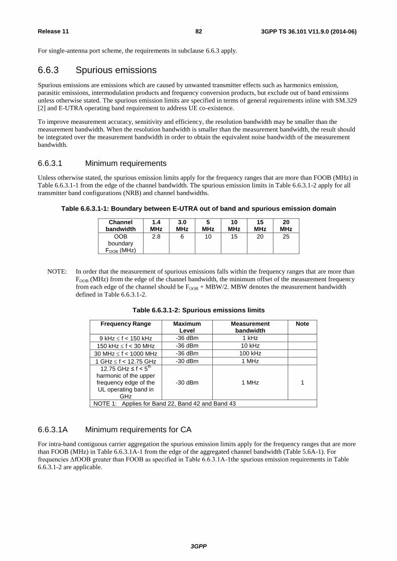
Release 11
3GPP
3GPP TS 36.101 V11.9.0 (2014-06) 82
For single-antenna port scheme, the requirements in subclause 6.6.3 apply.
6.6.3 Spurious emissions
Spurious emissions are emissions which are caused by unwanted transmitter effects such as harmonics emission,
parasitic emissions, intermodulation products and frequency conversion products, but exclude out of band emissions
unless otherwise stated. The spurious emission limits are specified in terms of general requirements inline with SM.329
[2] and E-UTRA operating band requirement to address UE co-existence.
To improve measurement accuracy, sensitivity and efficiency, the resolution bandwidth may be smaller than the
measurement bandwidth. When the resolution bandwidth is smaller than the measurement bandwidth, the result should
be integrated over the measurement bandwidth in order to obtain the equivalent noise bandwidth of the measurement
bandwidth.
6.6.3.1 Minimum requirements
Unless otherwise stated, the spurious emission limits apply for the frequency ranges that are more than FOOB (MHz) in
Table 6.6.3.1-1 from the edge of the channel bandwidth. The spurious emission limits in Table 6.6.3.1-2 apply for all
transmitter band configurations (NRB) and channel bandwidths.
Table 6.6.3.1-1: Boundary between E-UTRA out of band and spurious emission domain
Channel bandwidth
1.4 MHz
3.0 MHz
5 MHz
10 MHz
15 MHz
20 MHz
OOB boundary
FOOB (MHz)
2.8 6 10 15 20 25
NOTE: In order that the measurement of spurious emissions falls within the frequency ranges that are more than
FOOB (MHz) from the edge of the channel bandwidth, the minimum offset of the measurement frequency
from each edge of the channel should be FOOB + MBW/2. MBW denotes the measurement bandwidth
defined in Table 6.6.3.1-2.
Table 6.6.3.1-2: Spurious emissions limits
Frequency Range Maximum Level
Measurement bandwidth
Note
9 kHz f < 150 kHz -36 dBm 1 kHz
150 kHz f < 30 MHz -36 dBm 10 kHz
30 MHz f < 1000 MHz -36 dBm 100 kHz
1 GHz f < 12.75 GHz -30 dBm 1 MHz
12.75 GHz ≤ f < 5th
harmonic of the upper frequency edge of the UL operating band in
GHz
-30 dBm 1 MHz 1
NOTE 1: Applies for Band 22, Band 42 and Band 43
6.6.3.1A Minimum requirements for CA
For intra-band contiguous carrier aggregation the spurious emission limits apply for the frequency ranges that are more
than FOOB (MHz) in Table 6.6.3.1A-1 from the edge of the aggregated channel bandwidth (Table 5.6A-1). For
frequencies ΔfOOB greater than FOOB as specified in Table 6.6.3.1A-1the spurious emission requirements in Table
6.6.3.1-2 are applicable.

Release 11
3GPP
3GPP TS 36.101 V11.9.0 (2014-06) 83
Table 6.6.3.1A-1: Boundary between E-UTRA out of band and spurious emission domain for intra-band contiguous carrier aggregation
CA Bandwidth Class OOB boundary FOOB
(MHz)
A Table 6.6.3.1-1
B FFS
C BWChannel_CA + 5
NOTE: In order that the measurement of spurious emissions falls within the frequency ranges that are more than
FOOB (MHz) from the edge of the channel bandwidth, the minimum offset of the measurement frequency
from each edge of the aggregated channel should be FOOB + MBW/2. MBW denotes the measurement
bandwidth defined in Table 6.6.3.1-2.
6.6.3.2 Spurious emission band UE co-existence
This clause specifies the requirements for the specified E-UTRA band, for coexistence with protected bands
NOTE: For measurement conditions at the edge of each frequency range, the lowest frequency of the
measurement position in each frequency range should be set at the lowest boundary of the frequency
range plus MBW/2. The highest frequency of the measurement position in each frequency range should
be set at the highest boundary of the frequency range minus MBW/2. MBW denotes the measurement
bandwidth defined for the protected band.

Release 11
3GPP
3GPP TS 36.101 V11.9.0 (2014-06) 84
Table 6.6.3.2-1: Requirements
E-UTRA Band
Spurious emission
Protected band Frequency range (MHz)
Maximum Level (dBm)
MBW (MHz)
Note
1 E-UTRA Band 1, 7, 8, 11, 18, 19, 20, 21, 22, 26, 27, 28, 38, 40, 41, 42, 43, 44 FDL_low - FDL_high
-50 1
E-UTRA Band 3, 34 FDL_low - FDL_high -50 1 15
Frequency range 1880 1895 -40 1 15,27
Frequency range 1895 1915 -15.5 5 15, 26, 27
Frequency range 1915 1920 +1.6 5 15, 26, 27
Frequency range 1839.9 - 1879.9 -50 1 15
2 E-UTRA Band 4, 5, 10, 12, 13, 14, 17, 22, 23, 24, 26, 27, 28, 29, 41, 42 FDL_low - FDL_high
-50 1
E-UTRA Band 2, 25 FDL_low - FDL_high -50 1 15
E-UTRA Band 43 FDL_low - FDL_high -50 1 2
3 E-UTRA Band 1, 7, 8, 20, 26, 27, 28, 33, 34, 38, 41, 43, 44 FDL_low - FDL_high
-50 1
E-UTRA Band 3 FDL_low - FDL_high -50 1 15
E-UTRA Band 11, 18, 19, 21 FDL_low - FDL_high -50 1 13
E-UTRA Band 22, 42 FDL_low - FDL_high -50 1 2
Frequency range 1884.5 - 1915.7 -41 0.3 13
4 E-UTRA Band 2, 4, 5, 10, 12, 13, 14, 17, 22, 23, 24, 25, 26, 27, 28, 29, 41, 43 FDL_low - FDL_high
-50 1
E-UTRA Band 42 FDL_low - FDL_high -50 1 2
5 E-UTRA Band 2, 4, 5, 10, 12, 13, 14, 17, 22, 23, 24, 25, 28, 29,42, 43 FDL_low - FDL_high
-50 1
E-UTRA Band 41 FDL_low - FDL_high -50 1 2
E-UTRA Band 26 859 - 869 -27 1
6 E-UTRA Band 1, 9, 11, 34 FDL_low - FDL_high -50 1
Frequency range 860 - 875 -37 1
Frequency range 875 - 895 -50 1
Frequency range
1884.5 - 1919.6 -41 0.3
7
1884.5 - 1915.7 8
7 E-UTRA Band 1, 3, 7, 8, 20, 22, 27, 28, 29, 33, 34, 40, 42, 43 FDL_low - FDL_high
-50 1
Frequency range 2570 - 2575 +1.6 5 15, 21, 26
Frequency range 2575 - 2595 -15.5 5 15, 21, 26
Frequency range 2595 - 2620 -40 1 15, 21
8 E-UTRA Band 1, 20, 28, 33, 34, 38, 39, 40 FDL_low - FDL_high
-50 1
E-UTRA band 3 FDL_low - FDL_high -50 1 2
E-UTRA band 7 FDL_low - FDL_high -50 1 2
E-UTRA Band 8 FDL_low - FDL_high -50 1 15
E-UTRA Band 22, 41, 42, 43 FDL_low - FDL_high -50 1 2
E-UTRA Band 11, 21 FDL_low - FDL_high -50 1 23
Frequency range 860 - 890 -40 1 15, 23
Frequency range 1884.5 - 1915.7 -41 0.3 8, 23
9 E-UTRA Band 1, 11, 18, 19, 21, 26, 28, 34 FDL_low - FDL_high
-50 1
Frequency range 1884.5 - 1915.7 -41 0.3 8
Frequency range 945 - 960 -50 1
Frequency range 1839.9 - 1879.9 -50 1
Frequency range 2545 - 2575 -50 1
10 E-UTRA Band 2, 4, 5, 10, 12, 13, 14, 17, 23, 24, 25, 26, 27, 28, 29, 41, 43 FDL_low - FDL_high
-50 1
E-UTRA Band 22, 42 FDL_low - FDL_high -50 1 2
11 E-UTRA Band 1, 11, 18, 19, 21, 28, 34 FDL_low - FDL_high -50 1
Frequency range 1884.5 - 1915.7 -41 0.3 8
Frequency range 945 - 960 -50 1
Frequency range 1839.9 - 1879.9 -50 1
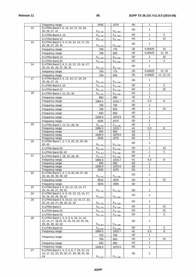
Release 11
3GPP
3GPP TS 36.101 V11.9.0 (2014-06) 85
Frequency range 2545 - 2575 -50 1
12 E-UTRA Band 2, 5, 13, 14, 17, 23, 24, 25, 26, 27, 41 FDL_low - FDL_high
-50 1
E-UTRA Band 4, 10 FDL_low - FDL_high -50 1 2
E-UTRA Band 12 FDL_low - FDL_high -50 1 15
13 E-UTRA Band 2, 4, 5, 10, 12, 13, 17, 23, 25, 26, 27, 29, 41 FDL_low - FDL_high
-50 1
Frequency range 769 - 775 -35 0.00625 15
Frequency range 799 - 805 -35 0.00625 11, 15
E-UTRA Band 14 FDL_low - FDL_high -50 1 15
E-UTRA Band 24 FDL_low - FDL_high -50 1 2
14
E-UTRA Band 2, 4, 5, 10, 12, 13, 14, 17, 23, 24, 25, 26, 27, 29, 41 FDL_low - FDL_high
-50 1
Frequency range 769 - 775 -35 0.00625 12, 15
Frequency range 799 - 805 -35 0.00625 11, 12, 15
17 E-UTRA Band 2, 5, 13, 14, 17, 23, 24, 25, 26, 27, 41 FDL_low - FDL_high
-50 1
E-UTRA Band 4, 10 FDL_low - FDL_high -50 1 2
E-UTRA Band 12 FDL_low - FDL_high -50 1 15
18 E-UTRA Band 1, 11, 21, 34 FDL_low - FDL_high -50 1
Frequency range 860 - 890 -40 1
Frequency range 1884.5 - 1915.7 -41 0.3 8
Frequency range 758 - 799 -50 1
Frequency range 799 - 803 -40 1 15
Frequency range 945 - 960 -50 1
Frequency range 1839.9 - 1879.9 -50 1
Frequency range 2545 - 2575 -50 1
19 E-UTRA Band 1, 11, 21, 28, 34 FDL_low - FDL_high -50 1
Frequency range 1884.5 - 1915.7 -41 0.3 8
Frequency range 945 - 960 -50 1
Frequency range 1839.9 - 1879.9 -50 1
Frequency range 2545 - 2575 -50 1
20 E-UTRA Band 1, 3, 7, 8, 20, 22, 33, 34, 40, 43 FDL_low - FDL_high
-50 1
E-UTRA Band 20 FDL_low - FDL_high -50 1 15
E-UTRA Band 38, 42 FDL_low - FDL_high -50 1 2
21 E-UTRA Band 1, 18, 19, 28, 34 FDL_low - FDL_high -50 1
Frequency range 1884.5 - 1915.7 -41 0.3 8
Frequency range 945 - 960 -50 1
Frequency range 1839.9 - 1879.9 -50 1
Frequency range 2545 - 2575 -50 1
22 E-UTRA Band 1, 3, 7, 8, 20, 26, 27, 28, 33, 34, 38, 39, 40, 43 FDL_low - FDL_high
-50 1
Frequency range 3510 - 3525 -40 1 15
Frequency range 3525 - 3590 -50 1
23 E-UTRA Band 4, 5, 10, 12, 13, 14, 17, 23, 24, 26, 27, 29, 41 FDL_low - FDL_high -50 1
24 E-UTRA Band 2, 4, 5, 10, 12, 13, 14, 17, 23, 24, 25, 26, 29, 41 FDL_low - FDL_high
-50 1
25 E-UTRA Band 4, 5, 10,12, 13, 14, 17, 22, 23, 24, 26, 27, 28, 29, 41, 42 FDL_low - FDL_high
-50 1
E-UTRA Band 2 FDL_low - FDL_high -50 1 15
E-UTRA Band 25 FDL_low - FDL_high -50 1 15
E-UTRA Band 43 FDL_low - FDL_high -50 1 2
26 E-UTRA Band 1, 2, 3, 4, 5, 10, 11, 12, 13, 14, 17, 18,19, 21, 22, 23, 24, 25, 26, 29, 34, 40, 42, 43 FDL_low - FDL_high
-50 1
E-UTRA Band 41 FDL_low - FDL_high -50 1 2
Frequency range 1884.5 - 1915.7 -41 0.3 8
Frequency range 703 - 799 -50 1
799 - 803 -40 1 15
Frequency range 945 - 960 -50 1
Frequency range 1839.9 - 1879.9 -50 1
27 E-UTRA Band 1, 2, 3, 4, 5, 7, 10, 12, 13, 14, 17, 22, 23, 25, 26, 27, 29, 38, 41, 42, 43 FDL_low - FDL_high
-50 1
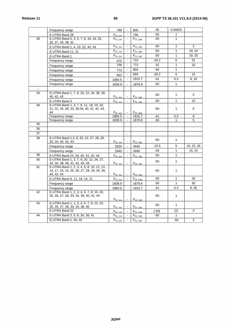
Release 11
3GPP
3GPP TS 36.101 V11.9.0 (2014-06) 86
Frequency range 799 - 805 -35 0.00625
E-UTRA Band 28 FDL_low - 790 -50 1
28 E-UTRA Band 2, 3, 5, 7, 8, 18, 19, 25, 26, 27, 34, 38, 41
FDL_low - FDL_high -50 1
E-UTRA Band 1, 4, 10, 22, 42, 43 FDL_low - FDL_high -50 1 2
E-UTRA Band 11, 21 FDL_low - FDL_high -50 1 19, 24
E-UTRA Band 1 FDL_low - FDL_high -50 1 19, 25
Frequency range 470 - 710 -26.2 6 31
Frequency range 758 - 773 -32 1 15
Frequency range 773 - 803 -50 1
Frequency range 662 - 694 -26.2 6 15
Frequency range 1884.5 - 1915.7 -41 0.3 8, 19
Frequency range 1839.9 - 1879.9 -50 1
…
33 E-UTRA Band 1, 7, 8, 20, 22, 34, 38, 39, 40, 42, 43 FDL_low - FDL_high
-50 1 5
E-UTRA Band 3 FDL_low - FDL_high -50 1 15
34 E-UTRA Band 1, 3, 7, 8, 11, 18, 19, 20, 21, 22, 26, 28, 33, 38,39, 40, 41, 42, 43, 44 FDL_low - FDL_high
-50 1 5
Frequency range 1884.5 - 1915.7 -41 0.3 8
Frequency range 1839.9 - 1879.9 -50 1 5
35
36
37 -
38 E-UTRA Band 1,3, 8, 20, 22, 27, 28, 29, 33, 34, 40, 42, 43 FDL_low - FDL_high
-50 1
Frequency range 2620 - 2645 -15.5 5 15, 22, 26
Frequency range 2645 - 2690 -40 1 15, 22
39 E-UTRA Band 22, 34, 40, 41, 42, 44 FDL_low - FDL_high -50 1
40 E-UTRA Band 1, 3, 7, 8, 20, 22, 26, 27, 33, 34, 38, 39, 41, 42, 43, 44 FDL_low - FDL_high
-50 1
41 E-UTRA Band 1, 2, 3, 4, 5, 8, 10, 12, 13 , 14, 17, 23, 24, 25, 26, 27, 28, 29, 34, 39, 40, 42, 44 FDL_low - FDL_high
-50 1
E-UTRA Band 9, 11, 18, 19, 21 FDL_low - FDL_high -50 1 30
Frequency range 1839.9 1879.9 -50 1 30
Frequency range 1884.5 1915.7 -41 0.3 8, 30
42 E-UTRA Band 1, 2, 3, 4, 5, 7, 8, 10, 20, 25, 26, 27, 28, 33, 34, 38, 40, 41, 44 FDL_low - FDL_high
-50 1
43 E-UTRA Band 1, 2, 3, 4, 5, 7, 8, 10, 20, 25, 26, 27, 28, 33, 34, 38, 40 FDL_low - FDL_high
-50 1
E-UTRA Band 22 FDL_low - FDL_high [-50] [1] 3
44 E-UTRA Band 3, 5, 8, 34, 39, 41 FDL_low - FDL_high -50 1
E-UTRA Band 1, 40, 42 FDL_low - FDL_high -50 2
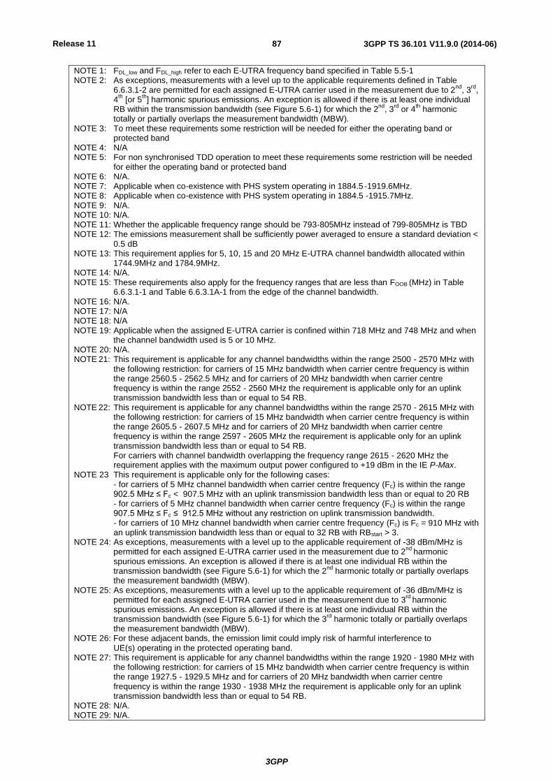
Release 11
3GPP
3GPP TS 36.101 V11.9.0 (2014-06) 87
NOTE 1: FDL_low and FDL_high refer to each E-UTRA frequency band specified in Table 5.5-1 NOTE 2: As exceptions, measurements with a level up to the applicable requirements defined in Table
6.6.3.1-2 are permitted for each assigned E-UTRA carrier used in the measurement due to 2nd
, 3rd
, 4
th [or 5
th] harmonic spurious emissions. An exception is allowed if there is at least one individual
RB within the transmission bandwidth (see Figure 5.6-1) for which the 2nd
, 3rd
or 4th
harmonic totally or partially overlaps the measurement bandwidth (MBW).
NOTE 3: To meet these requirements some restriction will be needed for either the operating band or protected band
NOTE 4: N/A NOTE 5: For non synchronised TDD operation to meet these requirements some restriction will be needed
for either the operating band or protected band NOTE 6: N/A. NOTE 7:
Applicable when co-existence with PHS system operating in 1884.5 -1919.6MHz.
NOTE 8:
Applicable when co-existence with PHS system operating in 1884.5 -1915.7MHz. NOTE 9:
N/A.
NOTE 10: N/A.
NOTE 11: Whether the applicable frequency range should be 793-805MHz instead of 799-805MHz is TBD
NOTE 12: The emissions measurement shall be sufficiently power averaged to ensure a standard deviation < 0.5 dB
NOTE 13: This requirement applies for 5, 10, 15 and 20 MHz E-UTRA channel bandwidth allocated within 1744.9MHz and 1784.9MHz.
NOTE 14: N/A. NOTE 15:
These requirements also apply for the frequency ranges that are less than FOOB (MHz) in Table 6.6.3.1-1 and Table 6.6.3.1A-1 from the edge of the channel bandwidth.
NOTE 16: N/A. NOTE 17: N/A NOTE 18: N/A NOTE 19:
Applicable when the assigned E-UTRA carrier is confined within 718 MHz and 748 MHz and when the channel bandwidth used is 5 or 10 MHz.
NOTE 20: N/A.
NOTE 21:
This requirement is applicable for any channel bandwidths within the range 2500 - 2570 MHz with the following restriction: for carriers of 15 MHz bandwidth when carrier centre frequency is within the range 2560.5 - 2562.5 MHz and for carriers of 20 MHz bandwidth when carrier centre frequency is within the range 2552 - 2560 MHz the requirement is applicable only for an uplink transmission bandwidth less than or equal to 54 RB.
NOTE 22:
This requirement is applicable for any channel bandwidths within the range 2570 - 2615 MHz with the following restriction: for carriers of 15 MHz bandwidth when carrier centre frequency is within the range 2605.5 - 2607.5 MHz and for carriers of 20 MHz bandwidth when carrier centre frequency is within the range 2597 - 2605 MHz the requirement is applicable only for an uplink transmission bandwidth less than or equal to 54 RB. For carriers with channel bandwidth overlapping the frequency range 2615 - 2620 MHz the requirement applies with the maximum output power configured to +19 dBm in the IE P-Max.
NOTE 23 This requirement is applicable only for the following cases: - for carriers of 5 MHz channel bandwidth when carrier centre frequency (Fc) is within the range 902.5 MHz ≤ Fc < 907.5 MHz with an uplink transmission bandwidth less than or equal to 20 RB - for carriers of 5 MHz channel bandwidth when carrier centre frequency (Fc) is within the range 907.5 MHz ≤ Fc ≤ 912.5 MHz without any restriction on uplink transmission bandwidth. - for carriers of 10 MHz channel bandwidth when carrier centre frequency (Fc) is Fc = 910 MHz with an uplink transmission bandwidth less than or equal to 32 RB with RBstart > 3.
NOTE 24: As exceptions, measurements with a level up to the applicable requirement of -38 dBm/MHz is permitted for each assigned E-UTRA carrier used in the measurement due to 2
nd harmonic
spurious emissions. An exception is allowed if there is at least one individual RB within the transmission bandwidth (see Figure 5.6-1) for which the 2
nd harmonic totally or partially overlaps
the measurement bandwidth (MBW). NOTE 25: As exceptions, measurements with a level up to the applicable requirement of -36 dBm/MHz is
permitted for each assigned E-UTRA carrier used in the measurement due to 3rd
harmonic spurious emissions. An exception is allowed if there is at least one individual RB within the transmission bandwidth (see Figure 5.6-1) for which the 3
rd harmonic totally or partially overlaps
the measurement bandwidth (MBW). NOTE 26: For these adjacent bands, the emission limit could imply risk of harmful interference to
UE(s) operating in the protected operating band. NOTE 27: This requirement is applicable for any channel bandwidths within the range 1920 - 1980 MHz with
the following restriction: for carriers of 15 MHz bandwidth when carrier centre frequency is within the range 1927.5 - 1929.5 MHz and for carriers of 20 MHz bandwidth when carrier centre frequency is within the range 1930 - 1938 MHz the requirement is applicable only for an uplink transmission bandwidth less than or equal to 54 RB.
NOTE 28: N/A. NOTE 29: N/A.
Release 11
3GPP
3GPP TS 36.101 V11.9.0 (2014-06) 88
NOTE 30: This requirement applies when the E-UTRA carrier is confined within 2545-2575 MHz and the channel bandwidth is 10 or 20 MHz.
NOTE 31: This requirement is applicable for 5 and 10 MHz E-UTRA channel bandwidth allocated within 718-728MHz. For carriers of 10 MHz bandwidth, this requirement applies for an uplink transmission bandwidth less than or equal to [30] RB with [RBstart > 1] and RBstart<48.
6.6.3.2A Spurious emission band UE co-existence for CA
This clause specifies the requirements for the specified carrier aggregation configurations for coexistence with protected
bands
NOTE: For measurement conditions at the edge of each frequency range, the lowest frequency of the
measurement position in each frequency range should be set at the lowest boundary of the frequency
range plus MBW/2. The highest frequency of the measurement position in each frequency range should
be set at the highest boundary of the frequency range minus MBW/2. MBW denotes the measurement
bandwidth defined for the protected band.
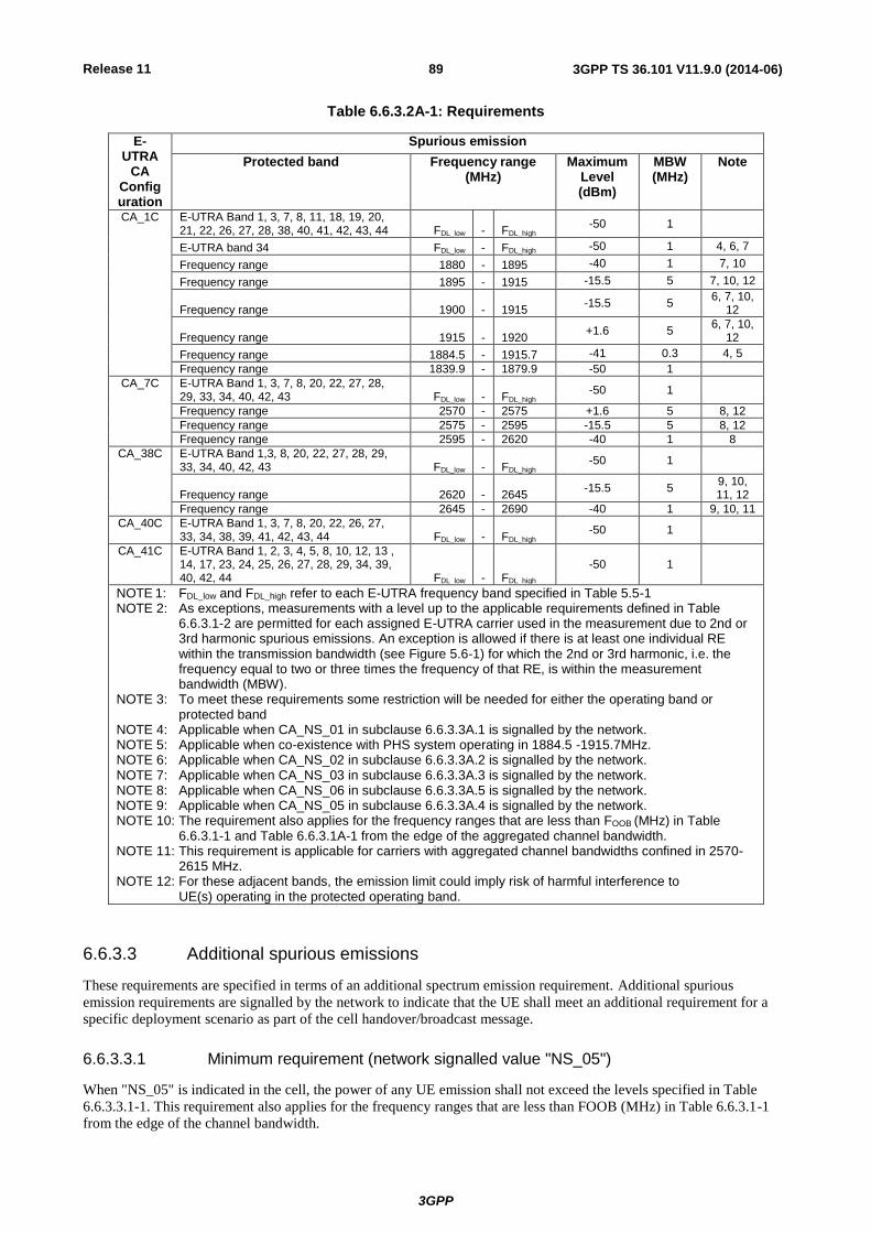
Release 11
3GPP
3GPP TS 36.101 V11.9.0 (2014-06) 89
Table 6.6.3.2A-1: Requirements
E-UTRA
CA Configuration
Spurious emission
Protected band Frequency range (MHz)
Maximum Level (dBm)
MBW (MHz)
Note
CA_1C E-UTRA Band 1, 3, 7, 8, 11, 18, 19, 20, 21, 22, 26, 27, 28, 38, 40, 41, 42, 43, 44 FDL_low - FDL_high
-50 1
E-UTRA band 34 FDL_low - FDL_high -50 1 4, 6, 7
Frequency range 1880 - 1895 -40 1 7, 10
Frequency range 1895 - 1915 -15.5 5 7, 10, 12
Frequency range 1900 - 1915 -15.5 5
6, 7, 10, 12
Frequency range 1915 - 1920 +1.6 5
6, 7, 10, 12
Frequency range 1884.5 - 1915.7 -41 0.3 4, 5
Frequency range 1839.9 - 1879.9 -50 1
CA_7C E-UTRA Band 1, 3, 7, 8, 20, 22, 27, 28, 29, 33, 34, 40, 42, 43 FDL_low - FDL_high
-50 1
Frequency range 2570 - 2575 +1.6 5 8, 12
Frequency range 2575 - 2595 -15.5 5 8, 12
Frequency range 2595 - 2620 -40 1 8
CA_38C E-UTRA Band 1,3, 8, 20, 22, 27, 28, 29, 33, 34, 40, 42, 43 FDL_low - FDL_high
-50 1
Frequency range 2620 - 2645 -15.5 5
9, 10, 11, 12
Frequency range 2645 - 2690 -40 1 9, 10, 11
CA_40C E-UTRA Band 1, 3, 7, 8, 20, 22, 26, 27, 33, 34, 38, 39, 41, 42, 43, 44 FDL_low - FDL_high
-50 1
CA_41C E-UTRA Band 1, 2, 3, 4, 5, 8, 10, 12, 13 , 14, 17, 23, 24, 25, 26, 27, 28, 29, 34, 39, 40, 42, 44 FDL_low - FDL_high
-50 1
NOTE 1:
FDL_low and FDL_high refer to each E-UTRA frequency band specified in Table 5.5-1
NOTE 2:
As exceptions, measurements with a level up to the applicable requirements defined in Table 6.6.3.1-2 are permitted for each assigned E-UTRA carrier used in the measurement due to 2nd or 3rd harmonic spurious emissions. An exception is allowed if there is at least one individual RE within the transmission bandwidth (see Figure 5.6-1) for which the 2nd or 3rd harmonic, i.e. the frequency equal to two or three times the frequency of that RE, is within the measurement bandwidth (MBW).
NOTE 3:
To meet these requirements some restriction will be needed for either the operating band or protected band
NOTE 4:
Applicable when CA_NS_01 in subclause 6.6.3.3A.1 is signalled by the network. NOTE 5:
Applicable when co-existence with PHS system operating in 1884.5 -1915.7MHz.
NOTE 6:
Applicable when CA_NS_02 in subclause 6.6.3.3A.2 is signalled by the network. NOTE 7:
Applicable when CA_NS_03 in subclause 6.6.3.3A.3 is signalled by the network.
NOTE 8:
Applicable when CA_NS_06 in subclause 6.6.3.3A.5 is signalled by the network. NOTE 9: Applicable when CA_NS_05 in subclause 6.6.3.3A.4 is signalled by the network. NOTE 10: The requirement also applies for the frequency ranges that are less than FOOB (MHz) in Table
6.6.3.1-1 and Table 6.6.3.1A-1 from the edge of the aggregated channel bandwidth. NOTE 11: This requirement is applicable for carriers with aggregated channel bandwidths confined in 2570-
2615 MHz. NOTE 12: For these adjacent bands, the emission limit could imply risk of harmful interference to
UE(s) operating in the protected operating band.
6.6.3.3 Additional spurious emissions
These requirements are specified in terms of an additional spectrum emission requirement. Additional spurious
emission requirements are signalled by the network to indicate that the UE shall meet an additional requirement for a
specific deployment scenario as part of the cell handover/broadcast message.
6.6.3.3.1 Minimum requirement (network signalled value "NS_05")
When "NS_05" is indicated in the cell, the power of any UE emission shall not exceed the levels specified in Table
6.6.3.3.1-1. This requirement also applies for the frequency ranges that are less than FOOB (MHz) in Table 6.6.3.1-1
from the edge of the channel bandwidth.
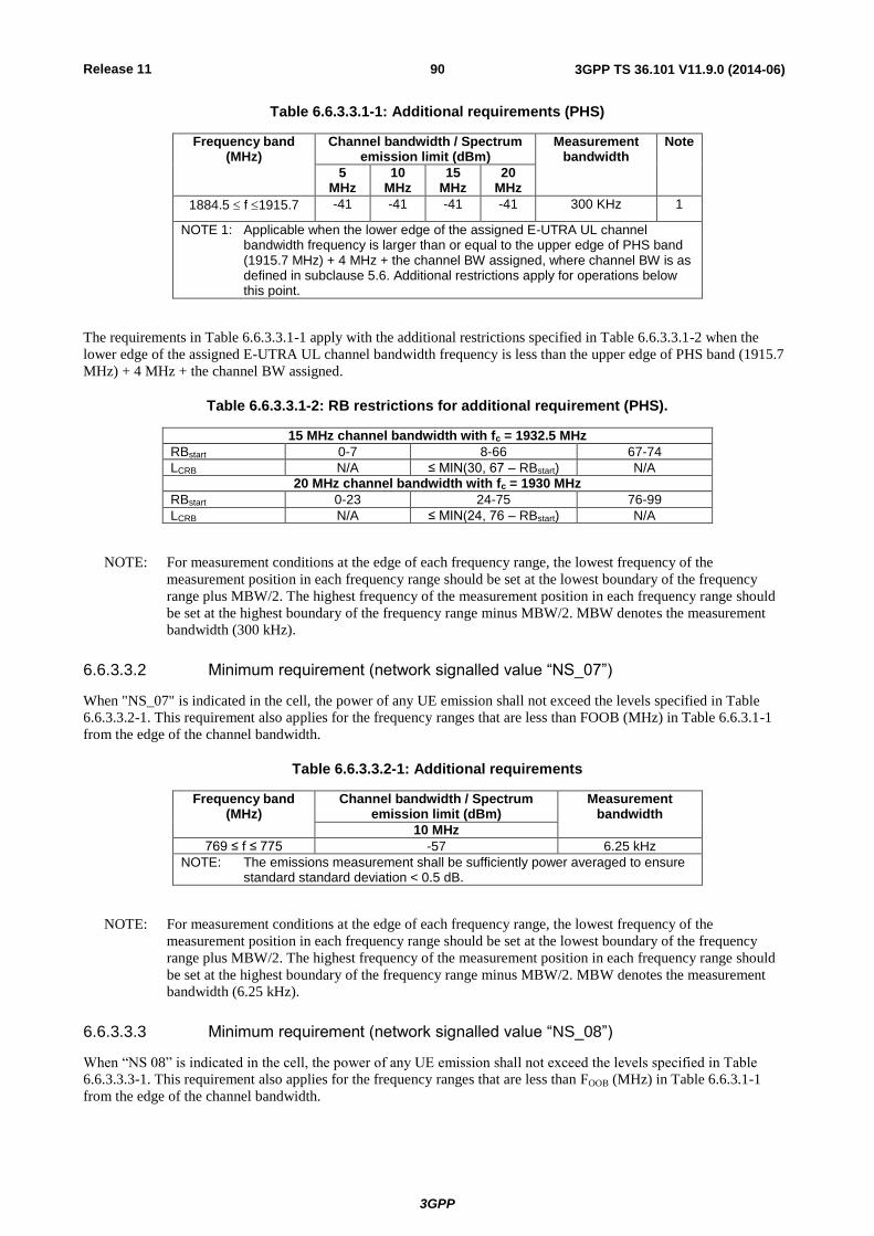
Release 11
3GPP
3GPP TS 36.101 V11.9.0 (2014-06) 90
Table 6.6.3.3.1-1: Additional requirements (PHS)
Frequency band (MHz)
Channel bandwidth / Spectrum emission limit (dBm)
Measurement bandwidth
Note
5 MHz
10 MHz
15 MHz
20 MHz
1884.5 f 1915.7 -41 -41 -41 -41 300 KHz 1
NOTE 1: Applicable when the lower edge of the assigned E-UTRA UL channel bandwidth frequency is larger than or equal to the upper edge of PHS band (1915.7 MHz) + 4 MHz + the channel BW assigned, where channel BW is as defined in subclause 5.6. Additional restrictions apply for operations below this point.
The requirements in Table 6.6.3.3.1-1 apply with the additional restrictions specified in Table 6.6.3.3.1-2 when the
lower edge of the assigned E-UTRA UL channel bandwidth frequency is less than the upper edge of PHS band (1915.7
MHz) + 4 MHz + the channel BW assigned.
Table 6.6.3.3.1-2: RB restrictions for additional requirement (PHS).
15 MHz channel bandwidth with fc = 1932.5 MHz
RBstart 0-7 8-66 67-74
LCRB N/A ≤ MIN(30, 67 – RBstart) N/A
20 MHz channel bandwidth with fc = 1930 MHz
RBstart 0-23 24-75 76-99
LCRB N/A ≤ MIN(24, 76 – RBstart) N/A
NOTE: For measurement conditions at the edge of each frequency range, the lowest frequency of the
measurement position in each frequency range should be set at the lowest boundary of the frequency
range plus MBW/2. The highest frequency of the measurement position in each frequency range should
be set at the highest boundary of the frequency range minus MBW/2. MBW denotes the measurement
bandwidth (300 kHz).
6.6.3.3.2 Minimum requirement (network signalled value “NS_07”)
When "NS_07" is indicated in the cell, the power of any UE emission shall not exceed the levels specified in Table
6.6.3.3.2-1. This requirement also applies for the frequency ranges that are less than FOOB (MHz) in Table 6.6.3.1-1
from the edge of the channel bandwidth.
Table 6.6.3.3.2-1: Additional requirements
Frequency band (MHz)
Channel bandwidth / Spectrum emission limit (dBm)
Measurement bandwidth
10 MHz
769 ≤ f ≤ 775 -57 6.25 kHz
NOTE: The emissions measurement shall be sufficiently power averaged to ensure standard standard deviation < 0.5 dB.
NOTE: For measurement conditions at the edge of each frequency range, the lowest frequency of the
measurement position in each frequency range should be set at the lowest boundary of the frequency
range plus MBW/2. The highest frequency of the measurement position in each frequency range should
be set at the highest boundary of the frequency range minus MBW/2. MBW denotes the measurement
bandwidth (6.25 kHz).
6.6.3.3.3 Minimum requirement (network signalled value “NS_08”)
When “NS 08” is indicated in the cell, the power of any UE emission shall not exceed the levels specified in Table
6.6.3.3.3-1. This requirement also applies for the frequency ranges that are less than FOOB (MHz) in Table 6.6.3.1-1
from the edge of the channel bandwidth.
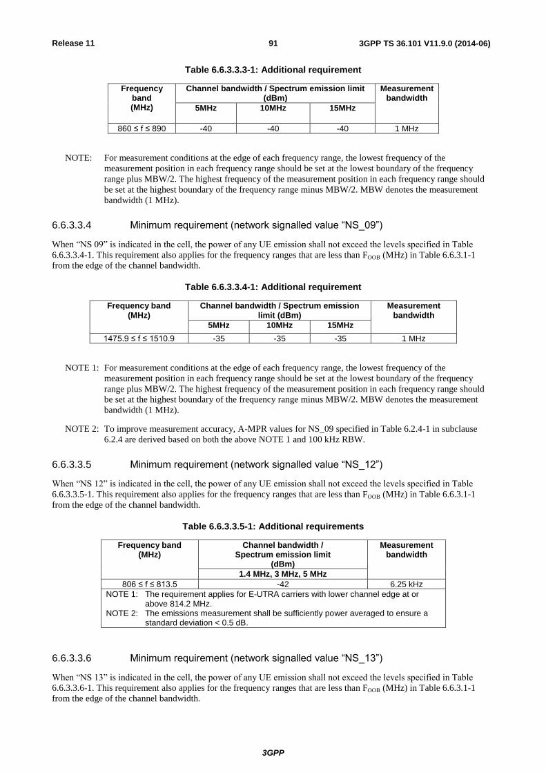
Release 11
3GPP
3GPP TS 36.101 V11.9.0 (2014-06) 91
Table 6.6.3.3.3-1: Additional requirement
Frequency band (MHz)
Channel bandwidth / Spectrum emission limit (dBm)
Measurement bandwidth
5MHz 10MHz 15MHz
860 ≤ f ≤ 890 -40 -40 -40 1 MHz
NOTE: For measurement conditions at the edge of each frequency range, the lowest frequency of the
measurement position in each frequency range should be set at the lowest boundary of the frequency
range plus MBW/2. The highest frequency of the measurement position in each frequency range should
be set at the highest boundary of the frequency range minus MBW/2. MBW denotes the measurement
bandwidth (1 MHz).
6.6.3.3.4 Minimum requirement (network signalled value “NS_09”)
When “NS 09” is indicated in the cell, the power of any UE emission shall not exceed the levels specified in Table
6.6.3.3.4-1. This requirement also applies for the frequency ranges that are less than FOOB (MHz) in Table 6.6.3.1-1
from the edge of the channel bandwidth.
Table 6.6.3.3.4-1: Additional requirement
Frequency band (MHz)
Channel bandwidth / Spectrum emission limit (dBm)
Measurement bandwidth
5MHz 10MHz 15MHz
1475.9 ≤ f ≤ 1510.9 -35 -35 -35 1 MHz
NOTE 1: For measurement conditions at the edge of each frequency range, the lowest frequency of the
measurement position in each frequency range should be set at the lowest boundary of the frequency
range plus MBW/2. The highest frequency of the measurement position in each frequency range should
be set at the highest boundary of the frequency range minus MBW/2. MBW denotes the measurement
bandwidth (1 MHz).
NOTE 2: To improve measurement accuracy, A-MPR values for NS_09 specified in Table 6.2.4-1 in subclause
6.2.4 are derived based on both the above NOTE 1 and 100 kHz RBW.
6.6.3.3.5 Minimum requirement (network signalled value “NS_12”)
When “NS 12” is indicated in the cell, the power of any UE emission shall not exceed the levels specified in Table
6.6.3.3.5-1. This requirement also applies for the frequency ranges that are less than FOOB (MHz) in Table 6.6.3.1-1
from the edge of the channel bandwidth.
Table 6.6.3.3.5-1: Additional requirements
Frequency band (MHz)
Channel bandwidth / Spectrum emission limit
(dBm)
Measurement bandwidth
1.4 MHz, 3 MHz, 5 MHz
806 ≤ f ≤ 813.5 -42 6.25 kHz
NOTE 1: The requirement applies for E-UTRA carriers with lower channel edge at or above 814.2 MHz.
NOTE 2: The emissions measurement shall be sufficiently power averaged to ensure a standard deviation < 0.5 dB.
6.6.3.3.6 Minimum requirement (network signalled value “NS_13”)
When “NS 13” is indicated in the cell, the power of any UE emission shall not exceed the levels specified in Table
6.6.3.3.6-1. This requirement also applies for the frequency ranges that are less than FOOB (MHz) in Table 6.6.3.1-1
from the edge of the channel bandwidth.

Release 11
3GPP
3GPP TS 36.101 V11.9.0 (2014-06) 92
Table 6.6.3.3.6-1: Additional requirements
Frequency band (MHz)
Channel bandwidth / Spectrum emission limit
(dBm)
Measurement bandwidth
5 MHz
806 ≤ f ≤ 816 -42 6.25 kHz
NOTE 1: The requirement applies for E-UTRA carriers with lower channel edge at or above 819 MHz.
NOTE 2: The emissions measurement shall be sufficiently power averaged to ensure a standard deviation < 0.5 dB.
6.6.3.3.7 Minimum requirement (network signalled value “NS_14”)
When “NS 14” is indicated in the cell, the power of any UE emission shall not exceed the levels specified in Table
6.6.3.3.7-1. This requirement also applies for the frequency ranges that are less than FOOB (MHz) in Table 6.6.3.1-1
from the edge of the channel bandwidth.
Table 6.6.3.3.7-1: Additional requirements
Frequency band (MHz)
Channel bandwidth / Spectrum emission limit
(dBm)
Measurement bandwidth
10 MHz, 15 MHz
806 ≤ f ≤ 816 -42 6.25 kHz
NOTE 1: The requirement applies for E-UTRA carriers with lower channel edge at or above 824 MHz.
NOTE 2: The emissions measurement shall be sufficiently power averaged to ensure a standard deviation < 0.5 dB.
6.6.3.3.8 Minimum requirement (network signalled value “NS_15”)
When “NS 15” is indicated in the cell, the power of any UE emission shall not exceed the levels specified in Table
6.6.3.3.8-1. This requirement also applies for the frequency ranges that are less than FOOB (MHz) in Table 6.6.3.1-1
from the edge of the channel bandwidth.
Table 6.6.3.3.8-1: Additional requirements
Frequency band (MHz)
Channel bandwidth / Spectrum emission limit
(dBm)
Measurement bandwidth
1.4 MHz, 3 MHz, 5 MHz, 10 MHz, 15 MHz
851 ≤ f ≤ 859 -53 6.25 kHz
NOTE 1: The emissions measurement shall be sufficiently power averaged to ensure a standard deviation < 0.5 dB.
6.6.3.3.9 Minimum requirement (network signalled value “NS_16”)
When “NS_16” is indicated in the cell, the power of any UE emission shall not exceed the levels specified in Table
6.6.3.3.9-1. This requirement also applies for the frequency ranges that are less than FOOB (MHz) in Table 6.6.3.1-1
from the edge of the channel bandwidth.
Table 6.6.3.3.9-1: Additional requirements
Frequency band (MHz)
Channel bandwidth / Spectrum emission limit (dBm)
Measurement bandwidth
Note
1.4, 3, 5, 10 MHz
790 ≤ f ≤ 803 -32 1 MHz

Release 11
3GPP
3GPP TS 36.101 V11.9.0 (2014-06) 93
6.6.3.3.10 Minimum requirement (network signalled value “NS_17”)
When “NS_17” is indicated in the cell, the power of any UE emission shall not exceed the levels specified in Table
6.6.3.3.10-1. This requirement also applies for the frequency ranges that are less than FOOB (MHz) in Table 6.6.3.3.1-1
from the edge of the channel bandwidth.
Table 6.6.3.3.10-1: Additional requirements
Frequency band (MHz)
Channel bandwidth / Spectrum emission limit (dBm)
Measurement bandwidth
Note
5, 10 MHz
470 ≤ f ≤ 710 -26.2 6 MHz 1
NOTE 1: Applicable when the assigned E-UTRA carrier is confined within 718 MHz and 748 MHz and when the channel bandwidth used is 5 or 10 MHz.
6.6.3.3.11 Minimum requirement (network signalled value “NS_18”)
When “NS_18” is indicated in the cell, the power of any UE emission shall not exceed the levels specified in Table
6.6.3.3.11-1. This requirement also applies for the frequency ranges that are less than FOOB (MHz) in Table 6.6.3.1-1
from the edge of the channel bandwidth.
Table 6.6.3.3.11-1: Additional requirements
Frequency band (MHz)
Channel bandwidth / Spectrum emission limit (dBm)
Measurement bandwidth
Note
5, 10, 15, 20 MHz
692-698 -26.2 6 MHz
6.6.3.3.12 Minimum requirement (network signalled value “NS_19”)
When “NS_19” is indicated in the cell, the power of any UE emission shall not exceed the levels specified in Table
6.6.3.3.12-1. This requirement also applies for the frequency ranges that are less than FOOB (MHz) in Table 6.6.3.1-1
from the edge of the channel bandwidth.
Table 6.6.3.3.12-1: Additional requirements
Frequency band (MHz)
Channel bandwidth / Spectrum emission limit (dBm)
Measurement bandwidth
Note
3, 5, 10, 15, 20 MHz
662 ≤ f ≤ 694 -25 8 MHz
6.6.3.3.13 Minimum requirement (network signalled value "NS_11")
When " NS_11" is indicated in the cell, the power of any UE emission shall not exceed the levels specified in Table
6.6.3.3.13-1. These requirements also apply for the frequency ranges that are less than FOOB (MHz) in Table 6.6.3.1-1
and Table 6.6.3.1A-1 from the edge of the channel bandwidth.
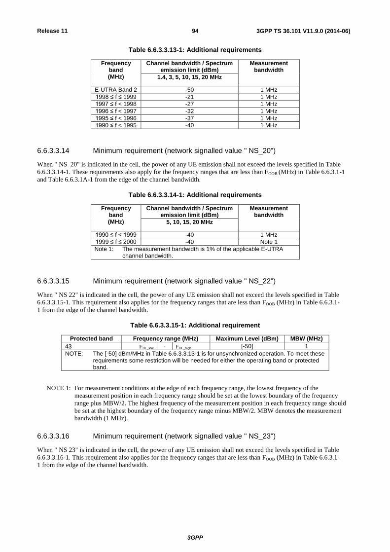
Release 11
3GPP
3GPP TS 36.101 V11.9.0 (2014-06) 94
Table 6.6.3.3.13-1: Additional requirements
Frequency band (MHz)
Channel bandwidth / Spectrum emission limit (dBm)
Measurement bandwidth
1.4, 3, 5, 10, 15, 20 MHz
E-UTRA Band 2 -50 1 MHz
1998 ≤ f ≤ 1999 -21 1 MHz
1997 ≤ f < 1998 -27 1 MHz
1996 ≤ f < 1997 -32 1 MHz
1995 ≤ f < 1996 -37 1 MHz
1990 ≤ f < 1995 -40 1 MHz
6.6.3.3.14 Minimum requirement (network signalled value " NS_20")
When " NS_20" is indicated in the cell, the power of any UE emission shall not exceed the levels specified in Table
6.6.3.3.14-1. These requirements also apply for the frequency ranges that are less than FOOB (MHz) in Table 6.6.3.1-1
and Table 6.6.3.1A-1 from the edge of the channel bandwidth.
Table 6.6.3.3.14-1: Additional requirements
Frequency band (MHz)
Channel bandwidth / Spectrum emission limit (dBm)
Measurement bandwidth
5, 10, 15, 20 MHz
1990 ≤ f < 1999 -40 1 MHz
1999 ≤ f ≤ 2000 -40 Note 1
Note 1: The measurement bandwidth is 1% of the applicable E-UTRA channel bandwidth.
6.6.3.3.15 Minimum requirement (network signalled value " NS_22")
When " NS 22" is indicated in the cell, the power of any UE emission shall not exceed the levels specified in Table
6.6.3.3.15-1. This requirement also applies for the frequency ranges that are less than FOOB (MHz) in Table 6.6.3.1-
1 from the edge of the channel bandwidth.
Table 6.6.3.3.15-1: Additional requirement
Protected band Frequency range (MHz) Maximum Level (dBm) MBW (MHz)
43 FDL_low - FDL_high [-50] 1
NOTE: The [-50] dBm/MHz in Table 6.6.3.3.13-1 is for unsynchronized operation. To meet these requirements some restriction will be needed for either the operating band or protected band.
NOTE 1: For measurement conditions at the edge of each frequency range, the lowest frequency of the
measurement position in each frequency range should be set at the lowest boundary of the frequency
range plus MBW/2. The highest frequency of the measurement position in each frequency range should
be set at the highest boundary of the frequency range minus MBW/2. MBW denotes the measurement
bandwidth (1 MHz).
6.6.3.3.16 Minimum requirement (network signalled value " NS_23")
When " NS 23" is indicated in the cell, the power of any UE emission shall not exceed the levels specified in Table
6.6.3.3.16-1. This requirement also applies for the frequency ranges that are less than FOOB (MHz) in Table 6.6.3.1-
1 from the edge of the channel bandwidth.

Release 11
3GPP
3GPP TS 36.101 V11.9.0 (2014-06) 95
Table 6.6.3.3.16-1: Additional requirement
Protected band Frequency range (MHz) Maximum Level (dBm) MBW (MHz)
42 FDL_low - FDL_high [-50] 1
NOTE: The [-50] dBm/MHz in Table 6.6.3.3.14-1 is for unsynchronized operation. To meet these requirements some restriction will be needed for either the operating band or protected band.
NOTE 1: For measurement conditions at the edge of each frequency range, the lowest frequency of the
measurement position in each frequency range should be set at the lowest boundary of the frequency
range plus MBW/2. The highest frequency of the measurement position in each frequency range should
be set at the highest boundary of the frequency range minus MBW/2. MBW denotes the measurement
bandwidth (1 MHz).
6.6.3.3A Additional spurious emissions for CA
These requirements are specified in terms of an additional spectrum emission requirement. Additional spurious
emission requirements are signalled by the network to indicate that the UE shall meet an additional requirement for a
specific deployment scenario as part of the cell reconfiguration message.
6.6.3.3A.1 Minimum requirement for CA_1C (network signalled value "CA_NS_01")
When "CA_NS_01" is indicated in the cell, the power of any UE emission shall not exceed the levels specified in Table
6.6.3.3A.1-1. This requirement also applies for the frequency ranges that are less than FOOB (MHz) in Table 6.6.3.1A-
1 from the edge of the aggregated channel bandwidth.
Table 6.6.3.3A.1-1: Additional requirements (PHS)
Protected band Frequency range (MHz) Maximum Level (dBm) MBW (MHz) Note
E-UTRA band 34 FDL_low - FDL_high -50 1
Frequency range 1884.5 - 1915.7 -41 0.3 1
NOTE 1: Applicable when the aggregated channel bandwidth is confined within frequency range 1940 – 1980 MHz
NOTE: For measurement conditions at the edge of each frequency range, the lowest frequency of the
measurement position in each frequency range should be set at the lowest boundary of the frequency
range plus MBW/2. The highest frequency of the measurement position in each frequency range should
be set at the highest boundary of the frequency range minus MBW/2. MBW denotes the measurement
bandwidth (300 kHz).
6.6.3.3A.2 Minimum requirement for CA_1C (network signalled value "CA_NS_02")
When "CA_NS_02" is indicated in the cell, the power of any UE emission shall not exceed the levels specified in Table
6.6.3.3A.2-1. This requirement also applies for the frequency ranges that are less than FOOB (MHz) in Table 6.6.3.1A-
1 from the edge of the aggregated channel bandwidth.
Table 6.6.3.3A.2-1: Additional requirements
Protected band Frequency range (MHz) Maximum Level (dBm) MBW (MHz)
E-UTRA band 34 FDL_low - FDL_high -50 1
Frequency range 1900 - 1915 -15.5 5
Frequency range 1915 - 1920 +1.6 5

Release 11
3GPP
3GPP TS 36.101 V11.9.0 (2014-06) 96
6.6.3.3A.3 Minimum requirement for CA_1C (network signalled value "CA_NS_03")
When "CA_NS_03" is indicated in the cell, the power of any UE emission shall not exceed the levels specified in Table
6.6.3.3A.3-1. This requirement also applies for the frequency ranges that are less than FOOB (MHz) in Table 6.6.3.1A-
1 from the edge of the aggregated channel bandwidth.
Table 6.6.3.3A.3-1: Additional requirements
Protected band Frequency range (MHz) Maximum Level (dBm) MBW (MHz)
E-UTRA band 34 FDL_low - FDL_high -50 1
Frequency range 1880 - 1895 -40 1
Frequency range 1895 - 1915 -15.5 5
Frequency range 1915 - 1920 +1.6 5
6.6.3.3A.4 Minimum requirement for CA_38C (network signalled value "CA_NS_05")
When "CA_NS_05" is indicated in the cell, the power of any UE emission shall not exceed the levels specified in Table
6.6.3.3A.4-1. This requirement also applies for the frequency ranges that are less than FOOB (MHz) in Table 6.6.3.1A-1
from the edge of the aggregated channel bandwidth. This requirement is applicable for carriers with aggregated channel
bandwidths confined in 2570 - 2615 MHz.
Table 6.6.3.3A.4-1: Additional requirements
Protected band Frequency range (MHz) Maximum Level (dBm) MBW (MHz)
Frequency range 2620 - 2645 -15.5 5
Frequency range 2645 - 2690 -40 1
6.6.3.3A.5 Minimum requirement for CA_7C (network signalled value "CA_NS_06")
When "CA_NS_06" is indicated in the cell, the power of any UE emission shall not exceed the levels specified in Table
6.6.3.3A.5-1. This requirement also applies for the frequency ranges that are less than FOOB (MHz) in Table 6.6.3.1A-1
from the edge of the aggregated channel bandwidth.
Table 6.6.3.3A.5-1: Additional requirements
Protected band Frequency range (MHz) Maximum Level (dBm) MBW (MHz)
Frequency range 2570 - 2575 +1.6 5
Frequency range 2575 - 2595 -15.5 5
Frequency range 2595 - 2620 -40 1
6.6.3A Void
<reserved for future use>
6.6.3B Spurious emission for UL-MIMO
For UE supporting UL-MIMO, the requirements for Spurious emissions which are caused by unwanted transmitter
effects such as harmonics emission, parasitic emissions, intermodulation products and frequency conversion products
are specified at each transmit antenna connector.
For UEs with two transmit antenna connectors in closed-loop spatial multiplexing scheme, the requirements in
subclause 6.6.3 apply to each transmit antenna connector. The requirements shall be met with the UL-MIMO
configurations specified in Table 6.2.2B-1.
For single-antenna port scheme, the general requirements in subclause 6.6.3 apply.

Release 11
3GPP
3GPP TS 36.101 V11.9.0 (2014-06) 97
6.6A Void
6.6B Void
6.7 Transmit intermodulation
The transmit intermodulation performance is a measure of the capability of the transmitter to inhibit the generation of
signals in its non linear elements caused by presence of the wanted signal and an interfering signal reaching the
transmitter via the antenna.
6.7.1 Minimum requirement
User Equipment(s) transmitting in close vicinity of each other can produce intermodulation products, which can fall into
the UE, or eNode B receive band as an unwanted interfering signal. The UE intermodulation attenuation is defined by
the ratio of the mean power of the wanted signal to the mean power of the intermodulation product when an interfering
CW signal is added at a level below the wanted signal at each of the transmitter antenna port with the other antenna
port(s) if any is terminated. Both the wanted signal power and the intermodulation product power are measured through
E-UTRA rectangular filter with measurement bandwidth shown in Table 6.7.1-1.
The requirement of transmitting intermodulation is prescribed in Table 6.7.1-1.
Table 6.7.1-1: Transmit Intermodulation
BW Channel (UL) 5MHz 10MHz 15MHz 20MHz
Interference Signal Frequency Offset
5MHz 10MHz 10MHz 20MHz 15MHz 30MHz 20MHz 40MHz
Interference CW Signal Level
-40dBc
Intermodulation Product -29dBc -35dBc -29dBc -35dBc -29dBc -35dBc -29dBc -35dBc
Measurement bandwidth 4.5MHz 4.5MHz 9.0MHz 9.0MHz 13.5MHz 13.5MHz 18MHz 18MHz
6.7.1A Minimum requirement for CA
User Equipment(s) transmitting in close vicinity of each other can produce intermodulation products, which can fall into
the UE, or eNode B receive band as an unwanted interfering signal. The UE intermodulation attenuation is defined by
the ratio of the mean power of the wanted signal to the mean power of the intermodulation product on both component
carriers when an interfering CW signal is added at a level below the wanted signal at each of the transmitter antenna
port with the other antenna port(s) if any is terminated. Both the wanted signal power and the intermodulation product
power are measured through rectangular filter with measurement bandwidth shown in Table 6.7.1A-1.
For intra-band contiguous carrier aggregation the requirement of transmitting intermodulation is specified in Table
6.7.1A-1.
Table 6.7.1A-1: Transmit Intermodulation
CA bandwidth class(UL) C
Interference Signal Frequency Offset
BWChannel_CA 2*BWChannel_CA
Interference CW Signal Level
-40dBc
Intermodulation Product -29dBc -35dBc
Measurement bandwidth BWChannel_CA- 2* BWGB

Release 11
3GPP
3GPP TS 36.101 V11.9.0 (2014-06) 98
6.7.1B Minimum requirement for UL-MIMO
For UE supporting UL-MIMO, the transmit intermodulation requirements are specified at each transmit antenna
connector and the wanted signal is defined as the sum of output power at each transmit antenna connector.
For UEs with two transmit antenna connectors in closed-loop spatial multiplexing scheme, the requirements in
subclause 6.7.1 apply to each transmit antenna connector. The requirements shall be met with the UL-MIMO
configurations specified in Table 6.2.2B-2.
For single-antenna port scheme, the requirements in subclause 6.7.1 apply.
6.8 Void
6.8.1 Void
6.8A Void
6.8B Time alignment error for UL-MIMO
For UE(s) with multiple transmit antenna connectors supporting UL-MIMO, this requirement applies to frame timing
differences between transmissions on multiple transmit antenna connectors in the closed-loop spatial multiplexing
scheme.
The time alignment error (TAE) is defined as the average frame timing difference between any two transmissions on
different transmit antenna connectors.
6.8B.1 Minimum Requirements
For UE(s) with multiple transmit antenna connectors, the Time Alignment Error (TAE) shall not exceed 130 ns.
7 Receiver characteristics
7.1 General
Unless otherwise stated the receiver characteristics are specified at the antenna connector(s) of the UE. For UE(s) with
an integral antenna only, a reference antenna(s) with a gain of 0 dBi is assumed for each antenna port(s). UE with an
integral antenna(s) may be taken into account by converting these power levels into field strength requirements,
assuming a 0 dBi gain antenna. . For UEs with more than one receiver antenna connector, identical interfering signals
shall be applied to each receiver antenna port if more than one of these is used (diversity).
The levels of the test signal applied to each of the antenna connectors shall be as defined in the respective sections
below.
With the exception of subclause 7.3, the requirements shall be verified with the network signalling value NS_01
configured (Table 6.2.4-1).
All the parameters in clause 7 are defined using the UL reference measurement channels specified in Annexes A.2.2 and
A.2.3, the DL reference measurement channels specified in Annex A.3.2 and using the set-up specified in Annex C.3.1.
For the additional requirements for intra-band non-contiguous carrier aggregation, in-gap test refers to the case when
the interfering signal(s) is (are) located at a negative offset with respect to the the assigned channel frequency of the
highest carrier frequency; or located at a positive offset with respect to the assigned channel frequency of the lowest
carrier frequency.
For the additional requirements for intra-band non-contiguous carrier aggregation, out-of-gap test refers to the case
when the interfering signal(s) is (are) located at a positive offset with respect to the assigned channel frequency of the

Release 11
3GPP
3GPP TS 36.101 V11.9.0 (2014-06) 99
highest carrier frequency, or located at a negative offset with respect to the assigned channel frequency of the lowest
carrier frequency.
For the additional requirements for intra-band non-contiguous carrier aggregation with channel bandwidth larger than or
equal to 5 MHz, existing adjacent channel selectivity requirements, in-band blocking requirements and narrow band
blocking requirements shall be supported for in-gap tests only if the sub-block gap size satisfies the following condition
so that the interferer position does not change the nature of the core requirement tested:
Wgap ≥ (Interferer frequency offset 1) + (Interferer frequency offset 2) –0.5*( (Channel bandwidth 1) +
(Channel bandwidth 2) )
where the interferer frequency offset represents the interferer frequency offset per carrier specified in subclause 7.5.1 ,
subclause 7.6.1 and subclause 7.6.3.
7.2 Diversity characteristics
The requirements in Section 7 assume that the receiver is equipped with two Rx port as a baseline. These requirements
apply to all UE categories unless stated otherwise. Requirements for 4 ports are FFS. With the exception of subclause
7.9 all requirements shall be verified by using both (all) antenna ports simultaneously.
7.3 Reference sensitivity power level
The reference sensitivity power level REFSENS is the minimum mean power applied to both the UE antenna ports at
which the throughput shall meet or exceed the requirements for the specified reference measurement channel.
7.3.1 Minimum requirements (QPSK)
The throughput shall be ≥ 95% of the maximum throughput of the reference measurement channels as specified in
Annexes A.2.2, A.2.3 and A.3.2 (with one sided dynamic OCNG Pattern OP.1 FDD/TDD for the DL-signal as
described in Annex A.5.1.1/A.5.2.1) with parameters specified in Table 7.3.1-1 and Table 7.3.1-2
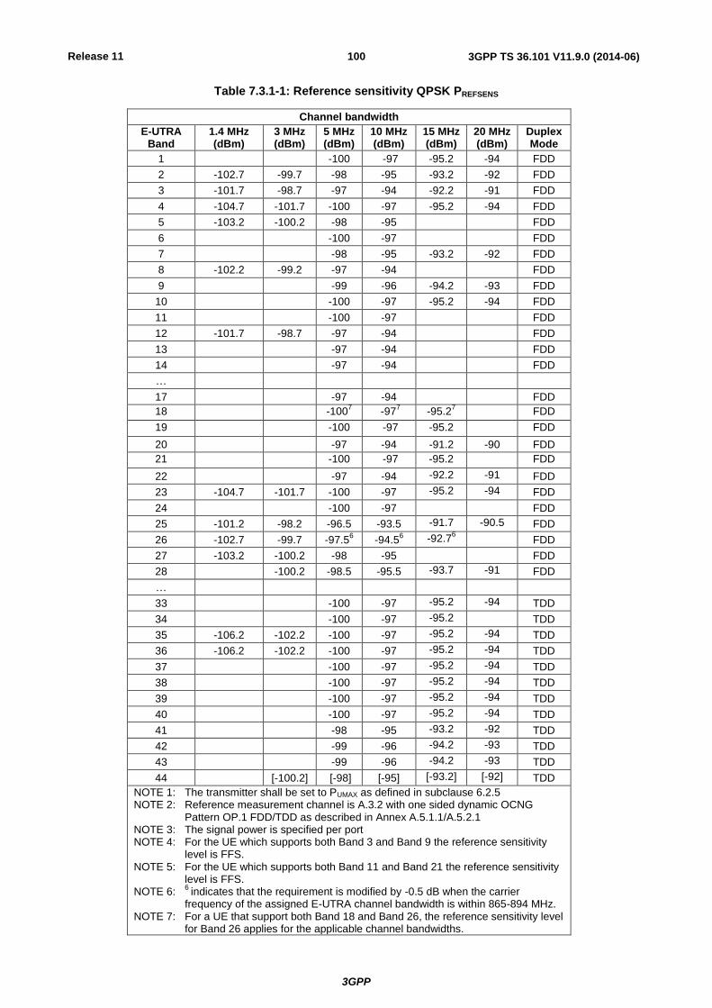
Release 11
3GPP
3GPP TS 36.101 V11.9.0 (2014-06) 100
Table 7.3.1-1: Reference sensitivity QPSK PREFSENS
Channel bandwidth
E-UTRA Band
1.4 MHz (dBm)
3 MHz (dBm)
5 MHz (dBm)
10 MHz (dBm)
15 MHz (dBm)
20 MHz (dBm)
Duplex Mode
1 -100 -97 -95.2 -94 FDD
2 -102.7 -99.7 -98 -95 -93.2 -92 FDD
3 -101.7 -98.7 -97 -94 -92.2 -91 FDD
4 -104.7 -101.7 -100 -97 -95.2 -94 FDD
5 -103.2 -100.2 -98 -95 FDD
6 -100 -97 FDD
7 -98 -95 -93.2 -92 FDD
8 -102.2 -99.2 -97 -94 FDD
9 -99 -96 -94.2 -93 FDD
10 -100 -97 -95.2 -94 FDD
11 -100 -97 FDD
12 -101.7 -98.7 -97 -94 FDD
13 -97 -94 FDD
14 -97 -94 FDD
…
17 -97 -94 FDD
18 -1007 -97
7 -95.2
7 FDD
19 -100 -97 -95.2 FDD
20 -97 -94 -91.2 -90 FDD
21 -100 -97 -95.2 FDD
22 -97 -94 -92.2 -91 FDD
23 -104.7 -101.7 -100 -97 -95.2 -94 FDD
24 -100 -97 FDD
25 -101.2 -98.2 -96.5 -93.5 -91.7 -90.5 FDD
26 -102.7 -99.7 -97.56 -94.5
6 -92.7
6 FDD
27 -103.2 -100.2 -98 -95 FDD
28 -100.2 -98.5 -95.5 -93.7 -91 FDD
…
33 -100 -97 -95.2 -94 TDD
34 -100 -97 -95.2 TDD
35 -106.2 -102.2 -100 -97 -95.2 -94 TDD
36 -106.2 -102.2 -100 -97 -95.2 -94 TDD
37 -100 -97 -95.2 -94 TDD
38 -100 -97 -95.2 -94 TDD
39 -100 -97 -95.2 -94 TDD
40 -100 -97 -95.2 -94 TDD
41 -98 -95 -93.2 -92 TDD
42 -99 -96 -94.2 -93 TDD
43 -99 -96 -94.2 -93 TDD
44 [-100.2] [-98] [-95] [-93.2] [-92] TDD
NOTE 1: The transmitter shall be set to PUMAX as defined in subclause 6.2.5 NOTE 2: Reference measurement channel is A.3.2 with one sided dynamic OCNG
Pattern OP.1 FDD/TDD as described in Annex A.5.1.1/A.5.2.1 NOTE 3: The signal power is specified per port NOTE 4: For the UE which supports both Band 3 and Band 9 the reference sensitivity
level is FFS. NOTE 5: For the UE which supports both Band 11 and Band 21 the reference sensitivity
level is FFS. NOTE 6:
6 indicates that the requirement is modified by -0.5 dB when the carrier
frequency of the assigned E-UTRA channel bandwidth is within 865-894 MHz. NOTE 7: For a UE that support both Band 18 and Band 26, the reference sensitivity level
for Band 26 applies for the applicable channel bandwidths.

Release 11
3GPP
3GPP TS 36.101 V11.9.0 (2014-06) 101
The reference receive sensitivity (REFSENS) requirement specified in Table 7.3.1-1 shall be met for an uplink
transmission bandwidth less than or equal to that specified in Table 7.3.1-2.
NOTE: Table 7.3.1-2 is intended for conformance tests and does not necessarily reflect the operational conditions
of the network, where the number of uplink and downlink allocated resource blocks will be practically
constrained by other factors. Typical receiver sensitivity performance with HARQ retransmission enabled
and using a residual BLER metric relevant for e.g. Speech Services is given in the Annex X
(informative).
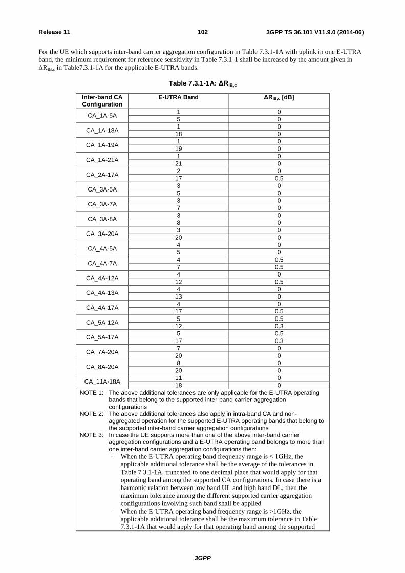
Release 11
3GPP
3GPP TS 36.101 V11.9.0 (2014-06) 102
For the UE which supports inter-band carrier aggregation configuration in Table 7.3.1-1A with uplink in one E-UTRA
band, the minimum requirement for reference sensitivity in Table 7.3.1-1 shall be increased by the amount given in
ΔRIB,c in Table7.3.1-1A for the applicable E-UTRA bands.
Table 7.3.1-1A: ΔRIB,c
Inter-band CA Configuration
E-UTRA Band ΔRIB,c [dB]
CA_1A-5A 1 0
5 0
CA_1A-18A 1 0
18 0
CA_1A-19A 1 0
19 0
CA_1A-21A 1 0
21 0
CA_2A-17A 2 0
17 0.5
CA_3A-5A 3 0
5 0
CA_3A-7A 3 0
7 0
CA_3A-8A 3 0
8 0
CA_3A-20A 3 0
20 0
CA_4A-5A 4 0
5 0
CA_4A-7A 4 0.5
7 0.5
CA_4A-12A 4 0
12 0.5
CA_4A-13A 4 0
13 0
CA_4A-17A 4 0
17 0.5
CA_5A-12A 5 0.5
12 0.3
CA_5A-17A 5 0.5
17 0.3
CA_7A-20A 7 0
20 0
CA_8A-20A 8 0
20 0
CA_11A-18A 11 0
18 0
NOTE 1: The above additional tolerances are only applicable for the E-UTRA operating bands that belong to the supported inter-band carrier aggregation configurations
NOTE 2: The above additional tolerances also apply in intra-band CA and non-aggregated operation for the supported E-UTRA operating bands that belong to the supported inter-band carrier aggregation configurations
NOTE 3: In case the UE supports more than one of the above inter-band carrier aggregation configurations and a E-UTRA operating band belongs to more than one inter-band carrier aggregation configurations then:
- When the E-UTRA operating band frequency range is ≤ 1GHz, the
applicable additional tolerance shall be the average of the tolerances in
Table 7.3.1-1A, truncated to one decimal place that would apply for that
operating band among the supported CA configurations. In case there is a
harmonic relation between low band UL and high band DL, then the
maximum tolerance among the different supported carrier aggregation
configurations involving such band shall be applied
- When the E-UTRA operating band frequency range is >1GHz, the
applicable additional tolerance shall be the maximum tolerance in Table
7.3.1-1A that would apply for that operating band among the supported

Release 11
3GPP
3GPP TS 36.101 V11.9.0 (2014-06) 103
CA configurations
NOTE : The above additional tolerances do not apply to supported UTRA operating bands with frequency range
below 1 GHz that correspond to the E-UTRA operating bands that belong to the supported inter-band
carrier aggregation configurations when such bands are belonging only to band combination(s) where one
band is <1GHz and another band is >1.7GHz and there is no harmonic relationship between the low band
UL and high band DL. Otherwise the above additional tolerances also apply to supported UTRA
operating bands that correspond to the E-UTRA operating bands that belong to the supported inter-band
carrier aggregation configurations.

Release 11
3GPP
3GPP TS 36.101 V11.9.0 (2014-06) 104
Table 7.3.1-2: Uplink configuration for reference sensitivity
E-UTRA Band / Channel bandwidth / NRB / Duplex mode
E-UTRA Band
1.4 MHz 3 MHz 5 MHz 10 MHz 15 MHz 20 MHz Duplex Mode
1 25 50 75 100 FDD
2 6 15 25 50 501 50
1 FDD
3 6 15 25 50 501 50
1 FDD
4 6 15 25 50 75 100 FDD
5 6 15 25 251 FDD
6 25 251 FDD
7 25 50 75 751 FDD
8 6 15 25 251 FDD
9 25 50 501 50
1 FDD
10 25 50 75 100 FDD
11 25 251 FDD
12 6 15 201 20
1 FDD
13 201
201
FDD
14 151 15
1 FDD
...
17 201 20
1 FDD
18 25 251 25
1 FDD
19 25 251 25
1 FDD
20 25 201 20
3 20
3 FDD
21 25 251 25
1 FDD
22 25 50 501 50
1 FDD
23 6 15 25 50 75 100 FDD
24 25 50 FDD
25 6 15 25 50 501 50
1 FDD
26 6 15 25 251 25
1 FDD
27 6 15 25 251 FDD
28 15 25 251 25
1 25
1 FDD
…
33 25 50 75 100 TDD
34 25 50 75 TDD
35 6 15 25 50 75 100 TDD
36 6 15 25 50 75 100 TDD
37 25 50 75 100 TDD
38 25 50 75 100 TDD
39 25 50 75 100 TDD
40 25 50 75 100 TDD
41 25 50 75 100 TDD
42 25 50 75 100 TDD
43 25 50 75 100 TDD
44 15 25 50 75 100 TDD
NOTE 1: 1 refers to the UL resource blocks shall be located as close as possible to
the downlink operating band but confined within the transmission bandwidth configuration for the channel bandwidth (Table 5.6-1).
NOTE 2: For the UE which supports both Band 11 and Band 21 the uplink configuration for reference sensitivity is FFS.
NOTE 3: 3
refers to Band 20; in the case of 15MHz channel bandwidth, the UL resource blocks shall be located at RBstart 11 and in the case of 20MHz channel bandwidth, the UL resource blocks shall be located at RBstart 16
Unless given by Table 7.3.1-3, the minimum requirements specified in Tables 7.3.1-1 and 7.3.1-2 shall be verified with
the network signalling value NS_01 (Table 6.2.4-1) configured.
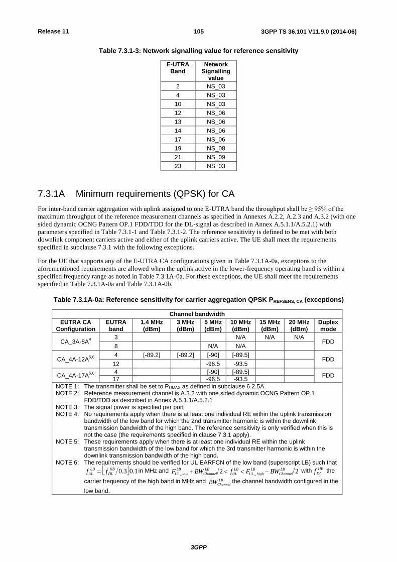
Release 11
3GPP
3GPP TS 36.101 V11.9.0 (2014-06) 105
Table 7.3.1-3: Network signalling value for reference sensitivity
E-UTRA Band
Network Signalling
value
2 NS_03
4 NS_03
10 NS_03
12 NS_06
13 NS_06
14 NS_06
17 NS_06
19 NS_08
21 NS_09
23 NS_03
7.3.1A Minimum requirements (QPSK) for CA
For inter-band carrier aggregation with uplink assigned to one E-UTRA band the throughput shall be ≥ 95% of the
maximum throughput of the reference measurement channels as specified in Annexes A.2.2, A.2.3 and A.3.2 (with one
sided dynamic OCNG Pattern OP.1 FDD/TDD for the DL-signal as described in Annex A.5.1.1/A.5.2.1) with
parameters specified in Table 7.3.1-1 and Table 7.3.1-2. The reference sensitivity is defined to be met with both
downlink component carriers active and either of the uplink carriers active. The UE shall meet the requirements
specified in subclause 7.3.1 with the following exceptions.
For the UE that supports any of the E-UTRA CA configurations given in Table 7.3.1A-0a, exceptions to the
aforementioned requirements are allowed when the uplink active in the lower-frequency operating band is within a
specified frequency range as noted in Table 7.3.1A-0a. For these exceptions, the UE shall meet the requirements
specified in Table 7.3.1A-0a and Table 7.3.1A-0b.
Table 7.3.1A-0a: Reference sensitivity for carrier aggregation QPSK PREFSENS, CA (exceptions)
Channel bandwidth
EUTRA CA Configuration
EUTRA band
1.4 MHz (dBm)
3 MHz (dBm)
5 MHz (dBm)
10 MHz (dBm)
15 MHz (dBm)
20 MHz (dBm)
Duplex mode
CA_3A-8A4
3 N/A N/A N/A FDD
8 N/A N/A
CA_4A-12A5,6
4 [-89.2] [-89.2] [-90] [-89.5]
FDD 12 -96.5 -93.5
CA_4A-17A5,6
4 [-90] [-89.5]
FDD 17 -96.5 -93.5
NOTE 1: The transmitter shall be set to PUMAX as defined in subclause 6.2.5A. NOTE 2: Reference measurement channel is A.3.2 with one sided dynamic OCNG Pattern OP.1
FDD/TDD as described in Annex A.5.1.1/A.5.2.1 NOTE 3: The signal power is specified per port NOTE 4: No requirements apply when there is at least one individual RE within the uplink transmission
bandwidth of the low band for which the 2nd transmitter harmonic is within the downlink transmission bandwidth of the high band. The reference sensitivity is only verified when this is not the case (the requirements specified in clause 7.3.1 apply).
NOTE 5: These requirements apply when there is at least one individual RE within the uplink transmission bandwidth of the low band for which the 3rd transmitter harmonic is within the downlink transmission bandwidth of the high band.
NOTE 6: The requirements should be verified for UL EARFCN of the low band (superscript LB) such that
1.03.0HB
DL
LB
UL ff in MHz and 22 __
LB
Channel
LB
highUL
LB
UL
LB
Channel
LB
lowUL BWFfBWF with HB
DLf the
carrier frequency of the high band in MHz and LB
ChannelBW the channel bandwidth configured in the
low band.

Release 11
3GPP
3GPP TS 36.101 V11.9.0 (2014-06) 106
Table 7.3.1A-0b: Uplink configuration for the low band (exceptions)
E-UTRA Band / Channel bandwidth of the high band / NRB / Duplex mode
EUTRA CA Configuration
UL band 1.4 MHz 3 MHz 5 MHz 10 MHz 15 MHz 20 MHz Duplex mode
CA_4A-12A 12 2 5 8 16 FDD
CA_4A-17A 17 8 16 FDD
NOTE 1: refers to the UL resource blocks, which shall be centred within the transmission bandwidth configuration for the channel bandwidth.
NOTE 2: the UL configuration applies regardless of the channel bandwidth of the low band unless the UL resource blocks exceed that specified in Table 7.3.1-2 for the uplink bandwidth in which case the allocation according to Table 7.3.1-2 applies.
For band combinations including operating bands without uplink band (as noted in Table 5.5-1), the requirements are
specified in Table 7.3.1A-0d and Table 7.3.1A-0e.
Table 7.3.1A-0d: Reference sensitivity QPSK PREFSENS
Channel bandwidth
EUTRA CA Configuration
EUTRA band
1.4 MHz (dBm)
3 MHz (dBm)
5 MHz (dBm)
10 MHz (dBm)
15 MHz (dBm)
20 MHz (dBm)
Duplex mode
CA_2A-29A 2 -98 -95
FDD 29 -98.7 -97 -94
CA_4A-29A 4 -100 -97
FDD 29 -98.7 -97 -94
NOTE 1: The transmitter shall be set to PUMAX as defined in subclause 6.2.5A. NOTE 2: Reference measurement channel is A.3.2 with one sided dynamic OCNG Pattern OP.1
FDD/TDD as described in Annex A.5.1.1/A.5.2.1 NOTE 3: The signal power is specified per port
Table 7.3.1A-0e: Uplink configuration for reference sensitivity
E-UTRA Band / Channel bandwidth / NRB / Duplex mode
EUTRA CA Configuration
EUTRA band
1.4 MHz (dBm)
3 MHz (dBm)
5 MHz (dBm)
10 MHz (dBm)
15 MHz (dBm)
20 MHz (dBm)
Duplex mode
CA_2A-29A 2 25 50
FDD 29 N/A N/A N/A
CA_4A-29A 4 25 50
FDD 29 N/A N/A N/A
In all cases for single uplink inter-band CA, unless given by Table 7.3.1-3 for the band with the active uplink carrier,
the applicable reference sensitivity requirements shall be verified with the network signalling value NS_01 (Table 6.2.4-
1) configured.
For intra-band contiguous carrier aggregation the throughput of each component carrier shall be ≥ 95% of the maximum
throughput of the reference measurement channels as specified in Annexes A.2.2, A.2.3 and A.3.2 (with one sided
dynamic OCNG Pattern OP.1 FDD/TDD for the DL-signal as described in Annex A.5.1.1/A.5.2.1) with parameters
specified in Table 7.3.1-1 and Table 7.3.1A-1. Table 7.3.1A-1 specifies the maximum number of allocated uplink
resource blocks for which the intra-band contiguous carrier aggregation reference sensitivity requirement shall be met.
The PCC and SCC allocations follow Table 7.3.1A-1 and form a contiguous allocation where TX–RX frequency
separations are as defined in Table 5.7.4-1. For UE(s) supporting one uplink carrier, the uplink configuration of the
PCC shall be in accordance with Table 7.3.1-2 and the downlink PCC carrier center frequency shall be configured
closer to uplink operating band than the downlink SCC center frequency. Unless given by Table 7.3.1-3, the reference
sensitivity requirements shall be verified with the network signalling value NS_01 (Table 6.2.4-1) configured.
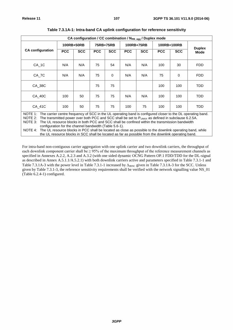
Release 11
3GPP
3GPP TS 36.101 V11.9.0 (2014-06) 107
Table 7.3.1A-1: Intra-band CA uplink configuration for reference sensitivity
CA configuration / CC combination / NRB_agg / Duplex mode
CA configuration
100RB+50RB 75RB+75RB 100RB+75RB 100RB+100RB Duplex Mode PCC SCC PCC SCC PCC SCC PCC SCC
CA_1C N/A N/A 75 54 N/A N/A 100 30 FDD
CA_7C N/A N/A 75 0 N/A N/A 75 0 FDD
CA_38C 75 75 100 100 TDD
CA_40C 100 50 75 75 N/A N/A 100 100 TDD
CA_41C 100 50 75 75 100 75 100 100 TDD
NOTE 1: The carrier centre frequency of SCC in the UL operating band is configured closer to the DL operating band. NOTE 2: The transmitted power over both PCC and SCC shall be set to PUMAX as defined in subclause 6.2.5A. NOTE 3: The UL resource blocks in both PCC and SCC shall be confined within the transmission bandwidth
configuration for the channel bandwidth (Table 5.6-1). NOTE 4: The UL resource blocks in PCC shall be located as close as possible to the downlink operating band, while
the UL resource blocks in SCC shall be located as far as possible from the downlink operating band.
For intra-band non-contiguous carrier aggregation with one uplink carrier and two downlink carriers, the throughput of
each downlink component carrier shall be ≥ 95% of the maximum throughput of the reference measurement channels as
specified in Annexes A.2.2, A.2.3 and A.3.2 (with one sided dynamic OCNG Pattern OP.1 FDD/TDD for the DL-signal
as described in Annex A.5.1.1/A.5.2.1) with both downlink carriers active and parameters specified in Table 7.3.1-1 and
Table 7.3.1A-3 with the power level in Table 7.3.1-1 increased by IBNC given in Table 7.3.1A-3 for the SCC. Unless
given by Table 7.3.1-3, the reference sensitivity requirements shall be verified with the network signalling value NS_01
(Table 6.2.4-1) configured.
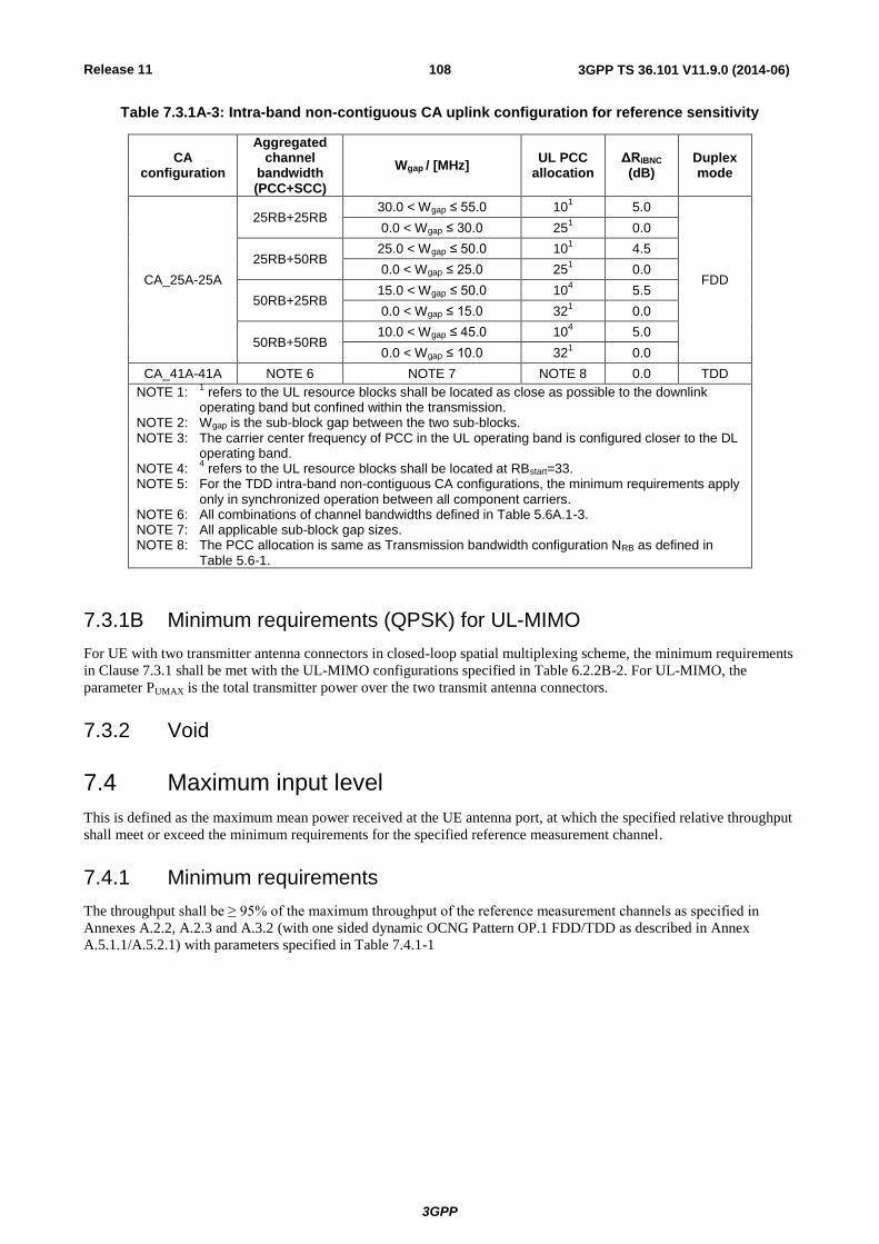
Release 11
3GPP
3GPP TS 36.101 V11.9.0 (2014-06) 108
Table 7.3.1A-3: Intra-band non-contiguous CA uplink configuration for reference sensitivity
CA configuration
Aggregated channel
bandwidth (PCC+SCC)
Wgap / [MHz] UL PCC
allocation ΔRIBNC (dB)
Duplex mode
CA_25A-25A
25RB+25RB 30.0 < Wgap ≤ 55.0 10
1 5.0
FDD
0.0 < Wgap ≤ 30.0 251
0.0
25RB+50RB 25.0 < Wgap ≤ 50.0 10
1 4.5
0.0 < Wgap ≤ 25.0 251
0.0
50RB+25RB 15.0 < Wgap ≤ 50.0 10
4 5.5
0.0 < Wgap ≤ 15.0 321
0.0
50RB+50RB 10.0 < Wgap ≤ 45.0 10
4 5.0
0.0 < Wgap ≤ 10.0 321
0.0
CA_41A-41A NOTE 6 NOTE 7 NOTE 8 0.0 TDD
NOTE 1: 1 refers to the UL resource blocks shall be located as close as possible to the downlink
operating band but confined within the transmission. NOTE 2: Wgap is the sub-block gap between the two sub-blocks. NOTE 3: The carrier center frequency of PCC in the UL operating band is configured closer to the DL
operating band. NOTE 4:
4 refers to the UL resource blocks shall be located at RBstart=33.
NOTE 5: For the TDD intra-band non-contiguous CA configurations, the minimum requirements apply only in synchronized operation between all component carriers.
NOTE 6: All combinations of channel bandwidths defined in Table 5.6A.1-3. NOTE 7: All applicable sub-block gap sizes. NOTE 8: The PCC allocation is same as Transmission bandwidth configuration NRB as defined in
Table 5.6-1.
7.3.1B Minimum requirements (QPSK) for UL-MIMO
For UE with two transmitter antenna connectors in closed-loop spatial multiplexing scheme, the minimum requirements
in Clause 7.3.1 shall be met with the UL-MIMO configurations specified in Table 6.2.2B-2. For UL-MIMO, the
parameter PUMAX is the total transmitter power over the two transmit antenna connectors.
7.3.2 Void
7.4 Maximum input level
This is defined as the maximum mean power received at the UE antenna port, at which the specified relative throughput
shall meet or exceed the minimum requirements for the specified reference measurement channel.
7.4.1 Minimum requirements
The throughput shall be ≥ 95% of the maximum throughput of the reference measurement channels as specified in
Annexes A.2.2, A.2.3 and A.3.2 (with one sided dynamic OCNG Pattern OP.1 FDD/TDD as described in Annex
A.5.1.1/A.5.2.1) with parameters specified in Table 7.4.1-1

Release 11
3GPP
3GPP TS 36.101 V11.9.0 (2014-06) 109
Table 7.4.1-1: Maximum input level
Rx Parameter Units Channel bandwidth
1.4 MHz
3 MHz
5 MHz
10 MHz
15 MHz
20 MHz
Power in Transmission Bandwidth Configuration
dBm -25
NOTE 1: The transmitter shall be set to 4dB below PCMAX_L at the minimum uplink configuration specified in Table 7.3.1-2 with PCMAX_L as defined in subclause 6.2.5.
NOTE 2: Reference measurement channel is Annex A.3.2: 64QAM, R=3/4 variant with one sided dynamic OCNG Pattern OP.1 FDD/TDD as described in Annex A.5.1.1/A.5.2.1.
7.4.1A Minimum requirements for CA
For inter-band carrier aggregation with uplink assigned to one E-UTRA band the maximum input level is defined with
the uplink active on the band other than the band whose downlink is being tested. The UE shall meet the requirements
specified in subclause 7.4.1 for each component carrier while both downlink carriers are active.
For intra-band contiguous carrier aggregation maximum input level is defined as a mean power received at the UE
antenna port over the aggregated channel bandwidth, at which the specified relative throughput shall meet or exceed the
minimum requirements for the specified reference measurement channel over each component carrier.
The downlink SCC shall be configured at nominal channel spacing to the PCC with the PCC configured closest to the
uplink band. Downlink PCC and SCC are both activated. The uplink output power shall be set as specified in Table
7.4.1A-1 with the uplink configuration set according to Table 7.3.1A-1 for the applicable carrier aggregation
configuration. For UE(s) supporting one uplink carrier, the uplink configuration of the PCC shall be in accordance with
Table 7.3.1-2.
The throughput shall be ≥ 95% of the maximum throughput of the reference measurement channels over each
component carrier as specified in Annexes A.2.2, A.2.3 and A.3.2 (with one sided dynamic OCNG Pattern OP.1
FDD/TDD as described in Annex A.5.1.1/A.5.2.1) with parameters specified in Table 7.4.1A-1.
For intra-band non-contiguous carrier aggregation with two downlink carriers the maximum input level requirement is –
22 dBm and is defined as a sum of mean carrier powers received at the UE antenna port while both carriers have equal
power. The throughput shall be ≥ 95% of the maximum throughput of the specified reference measurement channel as
specified in Annexes A.2.2, A.2.3 and A.3.2 (with one sided dynamic OCNG Pattern OP.1 FDD/TDD as described in
Annex A.5.1.1/A.5.2.1) over each carrier. For UE(s) supporting one uplink carrier, the uplink configuration of the PCC
shall be in accordance with Table 7.3.1A-3.
Table 7.4.1A-1: Maximum input level for intra-band contiguous CA
Rx Parameter Units CA Bandwidth Class
A B C D E F
Power in Transmission Aggregated Bandwidth Configuration
dBm -22
NOTE 1: The transmitter shall be set to 4dB below PCMAX_L or PCMAX_L_CA as defined in subclause 6.2.5A.
NOTE 2: Reference measurement channel is Annex A.3.2: 64QAM, R=3/4 variant with one sided dynamic OCNG Pattern OP.1 FDD/TDD as described in Annex A.5.1.1/A.5.2.1.
7.4.1B Minimum requirements for UL-MIMO
For UE with two transmitter antenna connectors in closed-loop spatial multiplexing, the minimum requirements in
Clause 7.4.1 shall be met with the UL-MIMO configurations specified in Table 6.2.2B-2. For UL-MIMO, the parameter
PCMAX_L is defined as the total transmitter power over the two transmit antenna connectors.
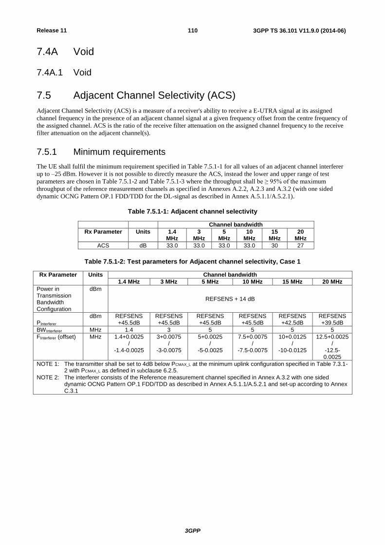
Release 11
3GPP
3GPP TS 36.101 V11.9.0 (2014-06) 110
7.4A Void
7.4A.1 Void
7.5 Adjacent Channel Selectivity (ACS)
Adjacent Channel Selectivity (ACS) is a measure of a receiver's ability to receive a E-UTRA signal at its assigned
channel frequency in the presence of an adjacent channel signal at a given frequency offset from the centre frequency of
the assigned channel. ACS is the ratio of the receive filter attenuation on the assigned channel frequency to the receive
filter attenuation on the adjacent channel(s).
7.5.1 Minimum requirements
The UE shall fulfil the minimum requirement specified in Table 7.5.1-1 for all values of an adjacent channel interferer
up to –25 dBm. However it is not possible to directly measure the ACS, instead the lower and upper range of test
parameters are chosen in Table 7.5.1-2 and Table 7.5.1-3 where the throughput shall be ≥ 95% of the maximum
throughput of the reference measurement channels as specified in Annexes A.2.2, A.2.3 and A.3.2 (with one sided
dynamic OCNG Pattern OP.1 FDD/TDD for the DL-signal as described in Annex A.5.1.1/A.5.2.1).
Table 7.5.1-1: Adjacent channel selectivity
Channel bandwidth
Rx Parameter Units 1.4 MHz
3 MHz
5 MHz
10 MHz
15 MHz
20 MHz
ACS dB 33.0 33.0 33.0 33.0 30 27
Table 7.5.1-2: Test parameters for Adjacent channel selectivity, Case 1
Rx Parameter Units Channel bandwidth
1.4 MHz 3 MHz 5 MHz 10 MHz 15 MHz 20 MHz
Power in Transmission Bandwidth Configuration
dBm
REFSENS + 14 dB
PInterferer dBm REFSENS
+45.5dB REFSENS +45.5dB
REFSENS +45.5dB
REFSENS +45.5dB
REFSENS +42.5dB
REFSENS +39.5dB
BWInterferer MHz 1.4 3 5 5 5 5
FInterferer (offset) MHz 1.4+0.0025 /
-1.4-0.0025
3+0.0075 /
-3-0.0075
5+0.0025 /
-5-0.0025
7.5+0.0075 /
-7.5-0.0075
10+0.0125 /
-10-0.0125
12.5+0.0025 /
-12.5-0.0025
NOTE 1: The transmitter shall be set to 4dB below PCMAX_L at the minimum uplink configuration specified in Table 7.3.1-2 with PCMAX_L as defined in subclause 6.2.5.
NOTE 2: The interferer consists of the Reference measurement channel specified in Annex A.3.2 with one sided dynamic OCNG Pattern OP.1 FDD/TDD as described in Annex A.5.1.1/A.5.2.1 and set-up according to Annex C.3.1

Release 11
3GPP
3GPP TS 36.101 V11.9.0 (2014-06) 111
Table 7.5.1-3: Test parameters for Adjacent channel selectivity, Case 2
Rx Parameter Units Channel bandwidth
1.4 MHz 3 MHz 5 MHz 10 MHz 15 MHz 20 MHz
Power in Transmission Bandwidth Configuration
dBm -56.5 -56.5 -56.5 -56.5 -53.5 -50.5
PInterferer dBm -25
BWInterferer MHz 1.4 3 5 5 5 5
FInterferer (offset) MHz 1.4+0.0025 /
-1.4-0.0025
3+0.0075 /
-3-0.0075
5+0.0025 /
-5-0.0025
7.5+0.0075 /
-7.5-0.0075
10+0.0125 /
-10-0.0125
12.5+0.0025 /
-12.5-0.0025
NOTE 1: The transmitter shall be set to 24dB below PCMAX_L at the minimum uplink configuration specified in Table 7.3.1-2 with PCMAX_L as defined in subclause 6.2.5.
NOTE 2: The interferer consists of the Reference measurement channel specified in Annex 3.2 with one sided dynamic OCNG Pattern OP.1 FDD/TDD as described in Annex A.5.1.1/A.5.2.1 and set-up according to Annex C.3.1.
7.5.1A Minimum requirements for CA
For inter-band carrier aggregation with uplink assigned to one E-UTRA band, the adjacent channel requirements are
defined with the uplink active on the band other than the band whose downlink is being tested. The UE shall meet the
requirements specified in subclause 7.5.1 for each component carrier while both downlink carriers are active. For E-
UTRA CA configurations including an operating band without uplink band (as noted in Table 5.5-1), the requirements
for both downlinks shall be met with the uplink active in the band capable of UL operation. For E-UTRA CA
configurations listed in Table 7.3.1A-0a under conditions for which reference sensitivity for the operating band being
tested is N/A, the adjacent channel requirements of subclause 7.5.1A do not apply.
For intra-band contiguous carrier aggregation the downlink SCC shall be configured at nominal channel spacing to the
PCC with the PCC configured closest to the uplink band. Downlink PCC and SCC are both activated. The uplink output
power shall be set as specified in Table 7.5.1A-2 and Table 7.5.1A-3 with the uplink configuration set according to
Table 7.3.1A-1 for the applicable carrier aggregation configuration. For UE(s) supporting one uplink carrier, the uplink
configuration of the PCC shall be in accordance with Table 7.3.1-2. The UE shall fulfil the minimum requirement
specified in Table 7.5.1A-1 for an adjacent channel interferer on either side of the aggregated downlink signal at a
specified frequency offset and for an interferer power up to -25 dBm. The throughput of each carrier shall be ≥ 95% of
the maximum throughput of the reference measurement channels as specified in Annexes A.2.2, A.2.3 and A.3.2 (with
one sided dynamic OCNG Pattern OP.1 FDD/TDD for the DL-signal as described in Annex A.5.1.1/A.5.2.1) with
parameters specified in Tables 7.5.1A-2 and 7.5.1A-3.
For intra-band non-contiguous carrier aggregation with one uplink carrier and two downlink carriers, each larger than or
equal to 5 MHz, the adjacent channel selectivity requirements are defined with the uplink configuration in accordance
with Table 7.3.1A-3. For this uplink configuration, the UE shall meet the requirements specified in subclause 7.5.1 for
each component carrier subject to in-gap and out-of-gap interferers while both downlink carriers are active. The
interferer powerPinterferer for Case 1 in Table 7.5.1-2 shall be set to the maximum of the levels given by the two downlink
carriers. For both Case 1 and Case 2 (Table 7.5.1-3), the wanted signal power level of each carrier shall be set in
accordance with the ACS requirement (Clause 7.5.1) relative to the interferer power P interferer.
Table 7.5.1A-1: Adjacent channel selectivity
CA Bandwidth Class
Rx Parameter Units B C D E F
ACS dB 24
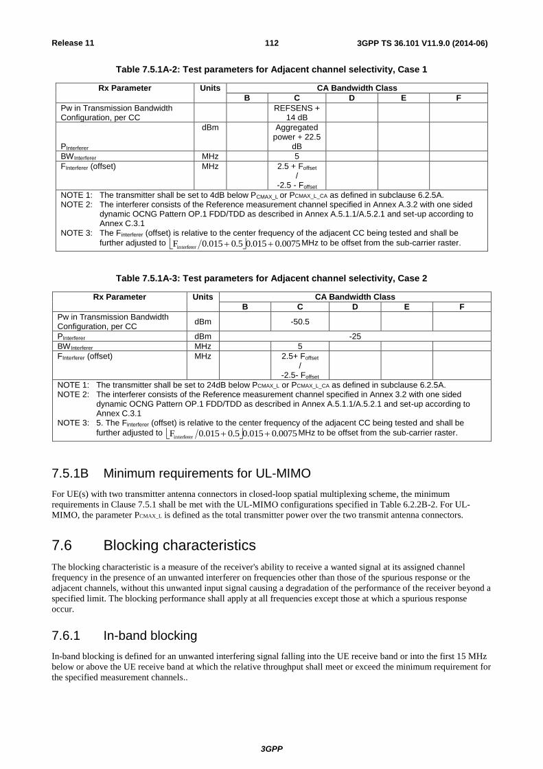
Release 11
3GPP
3GPP TS 36.101 V11.9.0 (2014-06) 112
Table 7.5.1A-2: Test parameters for Adjacent channel selectivity, Case 1
Rx Parameter Units CA Bandwidth Class
B C D E F
Pw in Transmission Bandwidth Configuration, per CC
REFSENS + 14 dB
PInterferer
dBm Aggregated power + 22.5
dB
BWInterferer MHz 5
FInterferer (offset) MHz 2.5 + Foffset /
-2.5 - Foffset
NOTE 1: The transmitter shall be set to 4dB below PCMAX_L or PCMAX_L_CA as defined in subclause 6.2.5A. NOTE 2: The interferer consists of the Reference measurement channel specified in Annex A.3.2 with one sided
dynamic OCNG Pattern OP.1 FDD/TDD as described in Annex A.5.1.1/A.5.2.1 and set-up according to Annex C.3.1
NOTE 3: The Finterferer (offset) is relative to the center frequency of the adjacent CC being tested and shall be
further adjusted to 0075.0015.00.50.015Finterferer MHz to be offset from the sub-carrier raster.
Table 7.5.1A-3: Test parameters for Adjacent channel selectivity, Case 2
Rx Parameter Units CA Bandwidth Class
B C D E F
Pw in Transmission Bandwidth Configuration, per CC
dBm -50.5
PInterferer dBm -25
BWInterferer MHz 5
FInterferer (offset)
MHz 2.5+ Foffset
/ -2.5- Foffset
NOTE 1: The transmitter shall be set to 24dB below PCMAX_L or PCMAX_L_CA as defined in subclause 6.2.5A. NOTE 2: The interferer consists of the Reference measurement channel specified in Annex 3.2 with one sided
dynamic OCNG Pattern OP.1 FDD/TDD as described in Annex A.5.1.1/A.5.2.1 and set-up according to Annex C.3.1
NOTE 3: 5. The Finterferer (offset) is relative to the center frequency of the adjacent CC being tested and shall be
further adjusted to 0075.0015.00.50.015Finterferer MHz to be offset from the sub-carrier raster.
7.5.1B Minimum requirements for UL-MIMO
For UE(s) with two transmitter antenna connectors in closed-loop spatial multiplexing scheme, the minimum
requirements in Clause 7.5.1 shall be met with the UL-MIMO configurations specified in Table 6.2.2B-2. For UL-
MIMO, the parameter PCMAX_L is defined as the total transmitter power over the two transmit antenna connectors.
7.6 Blocking characteristics
The blocking characteristic is a measure of the receiver's ability to receive a wanted signal at its assigned channel
frequency in the presence of an unwanted interferer on frequencies other than those of the spurious response or the
adjacent channels, without this unwanted input signal causing a degradation of the performance of the receiver beyond a
specified limit. The blocking performance shall apply at all frequencies except those at which a spurious response
occur.
7.6.1 In-band blocking
In-band blocking is defined for an unwanted interfering signal falling into the UE receive band or into the first 15 MHz
below or above the UE receive band at which the relative throughput shall meet or exceed the minimum requirement for
the specified measurement channels..

Release 11
3GPP
3GPP TS 36.101 V11.9.0 (2014-06) 113
7.6.1.1 Minimum requirements
The throughput shall be ≥ 95% of the maximum throughput of the reference measurement channels as specified in
Annexes A.2.2, A.2.3 and A.3.2 (with one sided dynamic OCNG Pattern OP.1 FDD/TDD for the DL-signal as
described in Annex A.5.1.1/A.5.2.1) with parameters specified in Tables 7.6.1.1-1 and 7.6.1.1-2.
Table 7.6.1.1-1: In band blocking parameters
Rx parameter Units Channel bandwidth
1.4 MHz 3 MHz 5 MHz 10 MHz 15 MHz 20 MHz
Power in Transmission Bandwidth Configuration
dBm
REFSENS + channel bandwidth specific value below
6 6 6 6 7 9
BWInterferer MHz 1.4 3 5 5 5 5
FIoffset, case 1 MHz 2.1+0.0125 4.5+0.0075 7.5+0.0125 7.5+0.0025 7.5+0.0075 7.5+0.0125
FIoffset, case 2 MHz 3.5+0.0075 7.5+0.0075 12.5+0.0075 12.5+0.0125
12.5+0.0025
12.5+0.0075
NOTE 1: The transmitter shall be set to 4dB below PCMAX_L at the minimum uplink configuration specified in Table 7.3.1-2 with PCMAX_L as defined in subclause 6.2.5.
NOTE 2: The interferer consists of the Reference measurement channel specified in Annex A.3.2 with one sided dynamic OCNG Pattern OP.1 FDD/TDD as described in Annex A.5.1.1/A.5.2.1 and set-up according to Annex C.3.1
Table 7.6.1.1-2: In-band blocking
E-UTRA band
Parameter Unit Case 1 Case 2 Case 3 Case 4 Case 5
PInterferer dBm -56 -44
Void Void
-38
FInterferer (offset)
MHz =-BW/2 – FIoffset,case 1
& =+BW/2 + FIoffset,case 1
≤-BW/2 – FIoffset,case 2 &
≥+BW/2 + FIoffset,case 2 -BW/2 - 11
1, 2, 3, 4, 5, 6, 7, 8, 9,
10, 11, 12, 13, 14, 17, 18, 19, 20, 21, 22, 23, 25, 26, 27, 28, 31, 33, 34, 35, 36, 37, 38, 39, 40, 41, 42,
43, 44
FInterferer MHz (Note 2) FDL_low – 15
to FDL_high + 15
30 FInterferer MHz (Note 2) FDL_low – 15
to FDL_high + 15
FDL_low – 11
NOTE 1: For certain bands, the unwanted modulated interfering signal may not fall inside the UE receive band, but within the first 15 MHz below or above the UE receive band
NOTE 2: For each carrier frequency the requirement is valid for two frequencies: a. the carrier frequency -BW/2 - FIoffset, case 1 and b. the carrier frequency +BW/2 + FIoffset, case 1
NOTE 3: FInterferer range values for unwanted modulated interfering signal are interferer center frequencies
For the UE which supports inter band CA configuration in Table 7.3.1-1A, PInterferer power defined in Table 7.6.1.1-2 is
increased by the amount given by ΔRIB,c in Table 7.3.1-1A.
7.6.1.1A Minimum requirements for CA
For inter-band carrier aggregation with uplink assigned to one E-UTRA band the in-band blocking requirements are
defined with the uplink active on the band other than the band whose downlink is being tested. The UE shall meet the
requirements specified in subclause 7.6.1.1 for each component carrier while both downlink carriers are active. For the
UE which supports inter band CA configuration in Table 7.3.1-1A, PInterferer power defined in Table 7.6.1.1-2 is
increased by the amount given by ΔRIB,c in Table 7.3.1-1A. For E-UTRA CA configurations including an operating
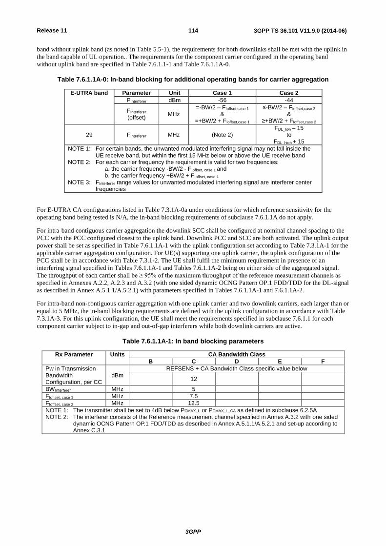
Release 11
3GPP
3GPP TS 36.101 V11.9.0 (2014-06) 114
band without uplink band (as noted in Table 5.5-1), the requirements for both downlinks shall be met with the uplink in
the band capable of UL operation.. The requirements for the component carrier configured in the operating band
without uplink band are specified in Table 7.6.1.1-1 and Table 7.6.1.1A-0.
Table 7.6.1.1A-0: In-band blocking for additional operating bands for carrier aggregation
E-UTRA band Parameter Unit Case 1 Case 2
PInterferer dBm -56 -44
FInterferer (offset)
MHz =-BW/2 – FIoffset,case 1
& =+BW/2 + FIoffset,case 1
≤-BW/2 – FIoffset,case 2 &
≥+BW/2 + FIoffset,case 2
29 FInterferer MHz (Note 2) FDL_low – 15
to FDL_high + 15
NOTE 1: For certain bands, the unwanted modulated interfering signal may not fall inside the UE receive band, but within the first 15 MHz below or above the UE receive band
NOTE 2: For each carrier frequency the requirement is valid for two frequencies: a. the carrier frequency -BW/2 - FIoffset, case 1 and b. the carrier frequency +BW/2 + FIoffset, case 1
NOTE 3: FInterferer range values for unwanted modulated interfering signal are interferer center frequencies
For E-UTRA CA configurations listed in Table 7.3.1A-0a under conditions for which reference sensitivity for the
operating band being tested is N/A, the in-band blocking requirements of subclause 7.6.1.1A do not apply.
For intra-band contiguous carrier aggregation the downlink SCC shall be configured at nominal channel spacing to the
PCC with the PCC configured closest to the uplink band. Downlink PCC and SCC are both activated. The uplink output
power shall be set as specified in Table 7.6.1.1A-1 with the uplink configuration set according to Table 7.3.1A-1 for the
applicable carrier aggregation configuration. For UE(s) supporting one uplink carrier, the uplink configuration of the
PCC shall be in accordance with Table 7.3.1-2. The UE shall fulfil the minimum requirement in presence of an
interfering signal specified in Tables 7.6.1.1A-1 and Tables 7.6.1.1A-2 being on either side of the aggregated signal.
The throughput of each carrier shall be ≥ 95% of the maximum throughput of the reference measurement channels as
specified in Annexes A.2.2, A.2.3 and A.3.2 (with one sided dynamic OCNG Pattern OP.1 FDD/TDD for the DL-signal
as described in Annex A.5.1.1/A.5.2.1) with parameters specified in Tables 7.6.1.1A-1 and 7.6.1.1A-2.
For intra-band non-contiguous carrier aggregation with one uplink carrier and two downlink carriers, each larger than or
equal to 5 MHz, the in-band blocking requirements are defined with the uplink configuration in accordance with Table
7.3.1A-3. For this uplink configuration, the UE shall meet the requirements specified in subclause 7.6.1.1 for each
component carrier subject to in-gap and out-of-gap interferers while both downlink carriers are active.
Table 7.6.1.1A-1: In band blocking parameters
Rx Parameter Units CA Bandwidth Class
B C D E F
Pw in Transmission Bandwidth Configuration, per CC
dBm REFSENS + CA Bandwidth Class specific value below
12
BWInterferer MHz 5
FIoffset, case 1 MHz 7.5
FIoffset, case 2 MHz 12.5
NOTE 1: The transmitter shall be set to 4dB below PCMAX_L or PCMAX_L_CA as defined in subclause 6.2.5A NOTE 2: The interferer consists of the Reference measurement channel specified in Annex A.3.2 with one sided
dynamic OCNG Pattern OP.1 FDD/TDD as described in Annex A.5.1.1/A.5.2.1 and set-up according to Annex C.3.1

Release 11
3GPP
3GPP TS 36.101 V11.9.0 (2014-06) 115
Table 7.6.1.1A-2: In-band blocking
CA configuration Parameter Unit Case 1 Case 2
PInterferer dBm -56 -44
FInterferer MHz =-Foffset– FIoffset,case 1
& =+Foffset + FIoffset,case 1
≤-Foffset– FIoffset,case 2 &
≥+Foffset + FIoffset,case 2
CA_1C, CA_7C, CA_38C, CA_40C, CA_41C
FInterferer (Range)
MHz (Note 2) FDL_low – 15
to FDL_high + 15
NOTE 1: For certain bands, the unwanted modulated interfering signal may not fall inside the UE receive band, but within the first 15 MHz below or above the UE receive band
NOTE 2: For each carrier frequency the requirement is valid for two frequencies: a. the carrier frequency -Foffset - FIoffset, case 1 and b. the carrier frequency +Foffset + FIoffset, case 1 NOTE 3: Foffset is the frequency offset from the center frequency of the adjacent CC being tested to the
edge of aggregated channel bandwidth. NOTE 4: The Finterferer (offset) is relative to the center frequency of the adjacent CC being tested and shall
be further adjusted to 0075.0015.05.00.015Finterferer MHz to be offset from the sub-carrier
raster.
7.6.2 Out-of-band blocking
Out-of-band band blocking is defined for an unwanted CW interfering signal falling more than 15 MHz below or above
the UE receive band. For the first 15 MHz below or above the UE receive band the appropriate in-band blocking or
adjacent channel selectivity in subclause 7.5.1 and subclause 7.6.1 shall be applied.
7.6.2.1 Minimum requirements
The throughput shall be ≥ 95% of the maximum throughput of the reference measurement channels as specified in
Annexes A.2.2, A.2.3 and A.3.2 (with one sided dynamic OCNG Pattern OP.1 FDD/TDD for the DL-signal as
described in Annex A.5.1.1/A.5.2.1) with parameters specified in Tables 7.6.2.1-1 and 7.6.2.1-2.
For Table 7.6.2.1-2 in frequency range 1, 2 and 3, up to 6/6,24max RBN exceptions are allowed for spurious
response frequencies in each assigned frequency channel when measured using a 1MHz step size, where RBN is the
number of resource blocks in the downlink transmission bandwidth configuration (see Figure 5.6-1). For these
exceptions the requirements of subclause 7.7 Spurious response are applicable.
For Table 7.6.2.1-2 in frequency range 4, up to 8/)2(,8max CRBsRB LN exceptions are allowed for spurious
response frequencies in each assigned frequency channel when measured using a 1MHz step size, where RBN is the
number of resource blocks in the downlink transmission bandwidth configurations (see Figure 5.6-1) and CRBsL is the
number of resource blocks allocated in the uplink. For these exceptions the requirements of clause 7.7 spurious response
are applicable.
Table 7.6.2.1-1: Out-of-band blocking parameters
Rx Parameter Units Channel bandwidth
1.4 MHz
3 MHz 5 MHz 10 MHz
15 MHz
20 MHz
Power in Transmission Bandwidth Configuration
dBm
REFSENS + channel bandwidth specific value below
6 6 6 6 7 9
NOTE 1: The transmitter shall be set to 4dB below PCMAX_L at the minimum uplink configuration specified in Table 7.3.1-2 with PCMAX_L as defined in subclause 6.2.5.
NOTE 2: Reference measurement channel is specified in Annex A.3.2 with one sided dynamic OCNG Pattern OP.1 FDD/TDD as described in Annex A.5.1.1/A.5.2.

Release 11
3GPP
3GPP TS 36.101 V11.9.0 (2014-06) 116
Table 7.6.2.1-2: Out of band blocking
E-UTRA band Parameter Units Frequency
Range 1 Range 2 Range 3 Range 4
PInterferer dBm -44 -30 -15 -15
1, 2, 3, 4, 5, 6, 7, 8, 9, 10, 11, 12, 13, 14, 17, 18, 19, 20, 21,
22, 23, 24, 25, 26, 27, 28, 33, 34, 35, 36, 37, 38, 39, 40, 41, 42, 43, 44
FInterferer
(CW) MHz
FDL_low -15 to FDL_low -60
FDL_low -60 to FDL_low -85
FDL_low -85 to 1 MHz
-
FDL_high +15 to FDL_high + 60
FDL_high +60 to FDL_high +85
FDL_high +85 to +12750 MHz
-
2, 5, 12, 17 FInterferer MHz - - - FUL_low - FUL_high
NOTE 1: For the UE which supports both Band 11 and Band 21 the out of blocking is FFS.
7.6.2.1A Minimum requirements for CA
For inter-band carrier aggregation with the uplink assigned to one E-UTRA band, the out-of-band blocking
requirements are defined with the uplink active on the band other than the band whose downlink is being tested. The
throughput in the downlink measured shall be ≥ 95% of the maximum throughput of the reference measurement
channels as specified in Annexes A.2.2, A.2.3 and A.3.2 (with one sided dynamic OCNG Pattern OP.1 FDD/TDD for
the DL-signal as described in Annex A.5.1.1/A.5.2.1) with parameters specified in Tables 7.6.2.1-1 and 7.6.2.1A-0. The
UE shall meet these requirements for each component carrier while both downlink carriers are active. For E-UTRA CA
configurations including an operating band without uplink band (as noted in Table 5.5-1), the requirements for both
downlinks shall be met with the uplink active in the band capable of UL operation. For E-UTRA CA configurations
listed in Table 7.3.1A-0a under conditions for which reference sensitivity for the operating band being tested is N/A, the
out-of-band blocking requirements of subclause 7.6.2.1A do not apply.
Table 7.6.2.1A-0: out-of-band blocking for inter-band carrier aggregation with one active uplink
Parameter Unit Range 1 Range 2 Range 3
Pw dBm Table 7.6.2.1-1 for both component carriers
Pinterferer dBm -44 + RIB,c -30 + RIB,c -15 + RIB,c
Finterferer (CW)
MHz -60 < f – FDL_Low(1) < -15 or
-60 < f – FDL_Low(2) < -15 or
15 < f – FDL_High(1) < 60 or
15 < f – FDL_High(2) < 60
-85 < f – FDL_Low(1) ≤ -60 or
-85 < f – FDL_Low(2) ≤ -60 or
60 ≤ f – FDL_High(1) < 85 or
60 ≤ f – FDL_High(2) < 85
1 ≤ f ≤ FDL_Low(1) – 85 or
FDL_High(1) + 85 ≤ f ≤ FDL_Low(2) – 85
or FDL_High(2) + 85 ≤ f
≤ 12750
NOTE 1: FDL_Low(1) and FDL_High(1) denote the respective lower and upper frequency limits of the lower operating band, FDL_Low(2) and FDL_High(2) the respective lower and upper frequency limits of the upper operating band.
NOTE 2: For FDL_Low(2) – FDL_High(1) < 145 MHz and FInterferer in FDL_High(1) < f < FDL_Low(2), FInterferer can be in both Range 1 and Range 2. Then the lower of the PInterferer applies.
NOTE 3: For FDL_Low(1) – 15 MHz ≤ f ≤ FDL_High(1) + 15 MHz and FDL_Low(2) – 15 MHz ≤ f ≤ FDL_High(2) + 15 MHz the appropriate adjacent channel selectivity and in-band blocking in the respective subclauses 7.5.1A and 7.6.1.1A shall be applied.
NOTE 4: RIB,c according to Table 7.3.1-1A applies when serving cell c is measured.
For Table 7.6.2.1A-0 in frequency ranges 1, 2 and 3, up to 6/6,24max RBN exceptions per downlink are allowed
for spurious response frequencies when measured using a step size of 1 MHz. For these exceptions the requirements in
clause 7.7.1A apply.
For intra-band contiguous carrier aggreagations the downlink SCC shall be configured at nominal channel spacing to
the PCC with the PCC configured closest to the uplink band. Downlink PCC and SCC are both activated. The uplink
output power shall be set as specified in Table 7.6.2.1A-1 with the uplink configuration set according to Table 7.3.1A-1
for the applicable carrier aggregation configuration. For UE(s) supporting one uplink carrier, the uplink configuration of
the PCC shall be in accordance with Table 7.3.1-2.

Release 11
3GPP
3GPP TS 36.101 V11.9.0 (2014-06) 117
The UE shall fulfil the minimum requirement in presence of an interfering signal specified in Tables 7.6.2.1A-1 and
Tables 7.6.2.1A-2 being on either side of the aggregated signal. The throughput of each carrier shall be ≥ 95% of the
maximum throughput of the reference measurement channels as specified in Annexes A.2.2, A.2.3 and A.3.2 (with one
sided dynamic OCNG Pattern OP.1 FDD/TDD for the DL-signal as described in Annex A.5.1.1/A.5.2.1) with
parameters specified in Tables 7.6.2.1A-1 and 7.6.2.1A-2.
For Table 7.6.2.1A-2 in frequency range 1, 2 and 3, up to 6/6,24max RBN exceptions are allowed for spurious
response frequencies in each assigned frequency channel when measured using a 1MHz step size. For these exceptions
the requirements of subclause 7.7 Spurious response are applicable.
Table 7.6.2.1A-1: Out-of-band blocking parameters
Rx Parameter Units CA Bandwidth Class
B C D E F
Pw in Transmission Bandwidth Configuration, per CC
dBm
REFSENS + CA Bandwidth Class specific value below
9
NOTE 1: The transmitter shall be set to 4dB below PCMAX_L or PCMAX_L_CA as defined in subclause 6.2.5A. NOTE 2: Reference measurement channel is specified in Annex A.3.2 with one sided dynamic OCNG Pattern OP.1
FDD/TDD as described in Annex A.5.1.1/A.5.2.
Table 7.6.2.1A-2: Out of band blocking
CA configuration Parameter Units Frequency
Range 1 Range 2 Range 3
PInterferer dBm -44 -30 -15
CA_1C, CA_3C, CA_7C , CA_38C, CA_40C, CA_41C
FInterferer
(CW)
MHz
FDL_low -15 to FDL_low -60
FDL_low -60 to FDL_low -85
FDL_low -85 to 1 MHz
FDL_high +15 to FDL_high + 60
FDL_high +60 to FDL_high +85
FDL_high +85 to +12750 MHz
For intra-band non-contiguous carrier aggregation with one uplink carrier and two downlink carriers, the out-of-band
blocking requirements are defined with the uplink configuration in accordance with table 7.3.1A-3. For this uplink
configuration, the UE shall meet the requirements specified in subclause 7.6.2.1 for each component carrier while both
downlink carriers are active.
For Table 7.6.2.1-2 in frequency range 1, 2 and 3, up to 6/6,24max RBN exceptions per assigned E-UTRA channel
per sub-block of the E-UTRA CA configuration are allowed for spurious response frequencies when measured using a
1MHz step size. For these exceptions the requirements of subclause 7.7 spurious response are applicable.
For Table 7.6.2.1-2 in frequency range 4, up to 8/)2(,8max CRBsRB LN exceptions per assigned E-UTRA channel
per sub-block of the E-UTRA CA configuration are allowed for spurious response frequencies when measured using a
1MHz step size. For these exceptions the requirements of clause 7.7 spurious response are applicable.
7.6.3 Narrow band blocking
This requirement is measure of a receiver's ability to receive a E-UTRA signal at its assigned channel frequency in the
presence of an unwanted narrow band CW interferer at a frequency, which is less than the nominal channel spacing.
7.6.3.1 Minimum requirements
The relative throughput shall be ≥ 95% of the maximum throughput of the reference measurement channels as specified
in Annexes A.2.2, A.2.3 and A.3.2 (with one sided dynamic OCNG Pattern OP.1 FDD/TDD for the DL-signal as
described in Annex A.5.1.1/A.5.2.1) with parameters specified in Table 7.6.3.1-1

Release 11
3GPP
3GPP TS 36.101 V11.9.0 (2014-06) 118
Table 7.6.3.1-1: Narrow-band blocking
Parameter Unit Channel Bandwidth
1.4 MHz 3 MHz 5 MHz 10 MHz 15 MHz 20 MHz
Pw dBm PREFSENS + channel-bandwidth specific value below
22 18 16 13 14 16
Puw (CW) dBm -55 -55 -55 -55 -55 -55
Fuw (offset for
f = 15 kHz) MHz 0.9075 1.7025 2.7075 5.2125 7.7025 10.2075
Fuw (offset for
f = 7.5 kHz)MHz
NOTE 1: The transmitter shall be set a 4 dB below PCMAX_L at the minimum uplink configuration specified in Table 7.3.1-2 with PCMAX_L as defined in subclause 6.2.5.
NOTE 2: Reference measurement channel is specified in Annex A.3.2 with one sided dynamic OCNG Pattern OP.1 FDD/TDD as described in Annex A.5.1.1/A.5.2.1.
For the UE which supports inter-band CA configuration in Table 7.3.1-1A, PUW power defined in Table 7.6.3.1-1 is
increased by the amount given by ΔRIB,c in Table 7.3.1-1A.
7.6.3.1A Minimum requirements for CA
For inter-band carrier aggregation with uplink assigned to one E-UTRA band the narrow-band blocking requirements
are defined with the uplink active on the band other than the band whose downlink is being tested. The UE shall meet
the requirements specified in subclause 7.6.3.1 for each component carrier while both downlink carriers are active. For
E-UTRA CA configurations including an operating band without uplink band (as noted in Table 5.5-1), the
requirements for both downlinks shall be met with the uplink active in the band capable of UL operation. For E-UTRA
CA configurations listed in Table 7.3.1A-0a under conditions for which reference sensitivity for the operating band
being tested is N/A, the narrow-band blocking requirements of subclause 7.6.3.1A do not apply.
For intra-band contiguous carrier aggregation the downlink SCC shall be configured at nominal channel spacing to the
PCC with the PCC configured closest to the uplink band. Downlink PCC and SCC are both activated. The uplink output
power shall be set as specified in Table 7.6.3.1A-1 with the uplink configuration set according to Table 7.3.1A-1 for the
applicable carrier aggregation configuration. For UE(s) supporting one uplink, the uplink configuration of the PCC shall
be in accordance with Table 7.3.1-2. The UE shall fulfil the minimum requirement in presence of an interfering signal
specified in Table 7.6.3.1A-1 being on either side of the aggregated signal. The throughput of each carrier shall be ≥
95% of the maximum throughput of the reference measurement channels as specified in Annexes A.2.2, A.2.3 and
A.3.2 (with one sided dynamic OCNG Pattern OP.1 FDD/TDD for the DL-signal as described in Annex
A.5.1.1/A.5.2.1) with parameters specified in Table 7.6.3.1A-1.
For intra-band non-contiguous carrier aggregation with one uplink carrier and two downlink carriers, the narrow band
blocking requirements are defined with the uplink configuration in accordance with Table 7.3.1A-3. For this uplink
configuration, the UE shall meet the requirements specified in subclause 7.6.3.1 for each component carrier subject to
in-gap and out-of-gap interferers while both downlink carriers are active.
Table 7.6.3.1A-1: Narrow-band blocking
Parameter Unit CA Bandwidth Class
B C D E F
Pw in Transmission Bandwidth Configuration, per CC
dBm REFSENS + CA Bandwidth Class specific value below
164
Puw (CW) dBm -55
Fuw (offset for
f = 15 kHz) MHz
- Foffset – 0.2 /
+ Foffset + 0.2
Fuw (offset for
f = 7.5 kHz)MHz
NOTE 1: The transmitter shall be set to 4dB below PCMAX_L or PCMAX_L_CA as defined in subclause 6.2.5A. NOTE 2: Reference measurement channel is specified in Annex A.3.2 with one sided dynamic OCNG Pattern OP.1
FDD/TDD as described in Annex A.5.1.1/A.5.2.1. NOTE 3: The Finterferer (offset) is relative to the center frequency of the adjacent CC being tested and shall be further
adjusted to 0075.0015.00.5 0.015Finterferer MHz to be offset from the sub-carrier raster.
NOTE 4: The requirement is applied for the band combinations whose component carriers’ BW≥5 MHz.

Release 11
3GPP
3GPP TS 36.101 V11.9.0 (2014-06) 119
7.6A Void
<Reserved for future use>
7.6B Blocking characteristics for UL-MIMO
For UE with two transmitter antenna connectors in closed-loop spatial multiplexing scheme, the minimum requirements
in subclause 7.6 shall be met with the UL-MIMO configurations specified in Table 6.2.2B-2. For UL-MIMO, the
parameter PCMAX_L is defined as the total transmitter power over the two transmit antenna connectors.
7.7 Spurious response
Spurious response is a measure of the receiver's ability to receive a wanted signal on its assigned channel frequency
without exceeding a given degradation due to the presence of an unwanted CW interfering signal at any other frequency
at which a response is obtained i.e. for which the out of band blocking limit as specified in subclause 7.6.2 is not met.
7.7.1 Minimum requirements
The throughput shall be ≥ 95% of the maximum throughput of the reference measurement channels as specified in
Annexes A.2.2, A.2.3 and A.3.2 (with one sided dynamic OCNG Pattern OP.1 FDD/TDD for the DL-signal as
described in Annex A.5.1.1/A.5.2.1) with parameters specified in Tables 7.7.1-1 and 7.7.1-2.
Table 7.7.1-1: Spurious response parameters
Rx parameter Units Channel bandwidth
1.4 MHz 3 MHz 5 MHz 10 MHz 15 MHz 20 MHz
Power in Transmission Bandwidth Configuration
dBm
REFSENS + channel bandwidth specific value below
6 6 6 6 7 9
NOTE 1: The transmitter shall be set to 4dB below PCMAX_L at the minimum uplink configuration specified in Table 7.3.1-2.
N OTE 2: Reference measurement channel is specified in Annex A.3.2 with one sided dynamic OCNG Pattern OP.1 FDD/TDD as described in Annex A.5.1.1/A.5.2.1.
Table 7.7.1-2: Spurious response
Parameter Unit Level
PInterferer
(CW) dBm -44
FInterferer MHz Spurious response frequencies
For the UE which supports inter-band CA configuration in Table 7.3.1-1A, Pinterferer power defined in Table 7.7.1-2 is
increased by the amount given by ΔRIB,c in Table 7.3.1-1A.
7.7.1A Minimum requirements for CA
For inter-band carrier aggregation with uplink assigned to one E-UTRA band the spurious response requirements are
defined with the uplink active on the band other than the band whose downlink is being tested. The throughput
measured in each downlink with Finterferer in Table 7.6.2.1A-0 at spurious response frequencies shall be ≥ 95% of the
maximum throughput of the reference measurement channels as specified in Annexes A.2.2, A.2.3 and A.3.2 (with one
sided dynamic OCNG Pattern OP.1 FDD/TDD for the DL-signal as described in Annex A.5.1.1/A.5.2.1) with
parameters specified in Tables 7.7.1-1 and 7.7.1-2. The UE shall meet these requirements for each component carrier
while both downlink carriers are active. For E-UTRA CA configurations including an operating band without uplink
band (as noted in Table 5.5-1), the requirements for both downlinks shall be met with the uplink active in the band
capable of UL operation. For E-UTRA CA configurations listed in Table 7.3.1A-0a under conditions for which
reference sensitivity for the operating band being tested is N/A, the spurious response requirements of subclause 7.7.1A
do not apply.

Release 11
3GPP
3GPP TS 36.101 V11.9.0 (2014-06) 120
For intra-band contiguous carrier aggregation the downlink SCC shall be configured at nominal channel spacing to the
PCC with the PCC configured closest to the uplink band. Downlink PCC and SCC are both activated. The uplink output
power shall be set as specified in Table 7.7.1A-1 with the uplink configuration set according to Table 7.3.1A-1 for the
applicable carrier aggregation configuration. For UE(s) supporting one uplink carrier, the uplink configuration of the
PCC shall be in accordance with Table 7.3.1-2. The throughput of each carrier shall be ≥ 95% of the maximum
throughput of the reference measurement channels as specified in Annexes A.2.2, A.2.3 and A.3.2 (with one sided
dynamic OCNG Pattern OP.1 FDD/TDD for the DL-signal as described in Annex A.5.1.1/A.5.2.1) with parameters
specified in Tables 7.7.1A-1 and 7.7.1A-2.
For intra-band non-contiguous carrier aggregation with one uplink carrier and two downlink carriers, the spurious
response requirements are defined with the uplink configuration in accordance with Table 7.3.1A-3. For this uplink
configuration, the UE shall meet the requirements specified in clause 7.7.1 for each component carrier while both
downlink carriers are active.
Table 7.7.1A-1: Spurious response parameters
Rx Parameter Units CA Bandwidth Class
B C D E F
Pw in Transmission Bandwidth Configuration, per CC
dBm REFSENS + CA Bandwidth Class specific value below
9
NOTE 1: The transmitter shall be set to 4dB below PCMAX_L or PCMAX_L_CA as defined in subclause 6.2.5A. NOTE 2: Reference measurement channel is specified in Annex A.3.2 with one sided dynamic OCNG Pattern
OP.1 FDD/TDD as described in Annex A.5.1.1/A.5.2.1.
Table 7.7.1A-2: Spurious response
Parameter Unit Level
PInterferer
(CW) dBm -44
FInterferer MHz Spurious response frequencies
7.7.1B Minimum requirements for UL-MIMO
For UE with two transmitter antenna connectors in closed-loop spatial multiplexing scheme, the minimum requirements
in Clause 7.7.1 shall be met with the UL-MIMO configurations specified in Table 6.2.2B-2. For UL-MIMO, the
parameter PCMAX_L is defined as the total transmitter power over the two transmit antenna connectors.
7.8 Intermodulation characteristics
Intermodulation response rejection is a measure of the capability of the receiver to receiver a wanted signal on its
assigned channel frequency in the presence of two or more interfering signals which have a specific frequency
relationship to the wanted signal.
7.8.1 Wide band intermodulation
The wide band intermodulation requirement is defined following the same principles using modulated E-UTRA carrier
and CW signal as interferer.
7.8.1.1 Minimum requirements
The throughput shall be ≥ 95% of the maximum throughput of the reference measurement channels as specified in
Annexes A.2.2, A.2.3 and A.3.2 (with one sided dynamic OCNG Pattern OP.1 FDD/TDD for the DL-signal as
described in Annex A.5.1.1/A.5.2.1) with parameters specified in Table 7.8.1.1 for the specified wanted signal mean
power in the presence of two interfering signals
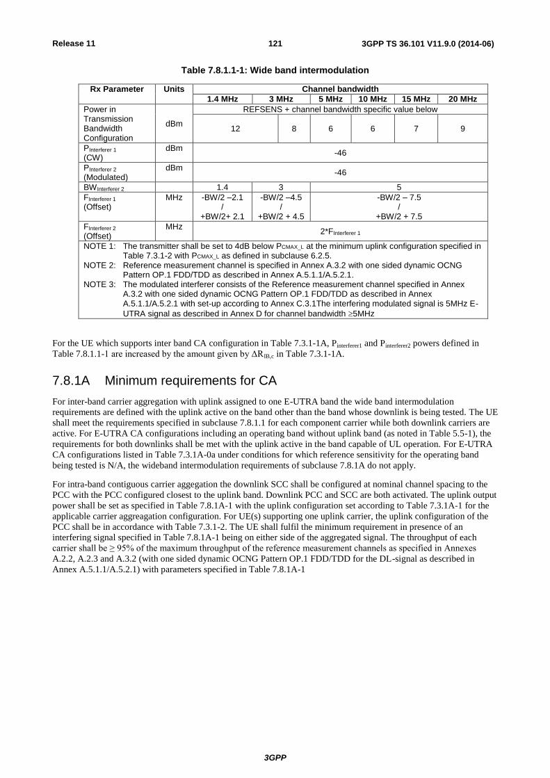
Release 11
3GPP
3GPP TS 36.101 V11.9.0 (2014-06) 121
Table 7.8.1.1-1: Wide band intermodulation
Rx Parameter Units Channel bandwidth
1.4 MHz 3 MHz 5 MHz 10 MHz 15 MHz 20 MHz
Power in Transmission Bandwidth Configuration
dBm
REFSENS + channel bandwidth specific value below
12 8 6 6 7 9
PInterferer 1 (CW)
dBm -46
PInterferer 2 (Modulated)
dBm -46
BWInterferer 2 1.4 3 5
FInterferer 1 (Offset)
MHz -BW/2 –2.1 /
+BW/2+ 2.1
-BW/2 –4.5 /
+BW/2 + 4.5
-BW/2 – 7.5 /
+BW/2 + 7.5
FInterferer 2 (Offset)
MHz 2*FInterferer 1
NOTE 1: The transmitter shall be set to 4dB below PCMAX_L at the minimum uplink configuration specified in Table 7.3.1-2 with PCMAX_L as defined in subclause 6.2.5.
NOTE 2: Reference measurement channel is specified in Annex A.3.2 with one sided dynamic OCNG Pattern OP.1 FDD/TDD as described in Annex A.5.1.1/A.5.2.1.
NOTE 3: The modulated interferer consists of the Reference measurement channel specified in Annex A.3.2 with one sided dynamic OCNG Pattern OP.1 FDD/TDD as described in Annex A.5.1.1/A.5.2.1 with set-up according to Annex C.3.1The interfering modulated signal is 5MHz E-
UTRA signal as described in Annex D for channel bandwidth 5MHz
For the UE which supports inter band CA configuration in Table 7.3.1-1A, Pinterferer1 and Pinterferer2 powers defined in
Table 7.8.1.1-1 are increased by the amount given by ΔRIB,c in Table 7.3.1-1A.
7.8.1A Minimum requirements for CA
For inter-band carrier aggregation with uplink assigned to one E-UTRA band the wide band intermodulation
requirements are defined with the uplink active on the band other than the band whose downlink is being tested. The UE
shall meet the requirements specified in subclause 7.8.1.1 for each component carrier while both downlink carriers are
active. For E-UTRA CA configurations including an operating band without uplink band (as noted in Table 5.5-1), the
requirements for both downlinks shall be met with the uplink active in the band capable of UL operation. For E-UTRA
CA configurations listed in Table 7.3.1A-0a under conditions for which reference sensitivity for the operating band
being tested is N/A, the wideband intermodulation requirements of subclause 7.8.1A do not apply.
For intra-band contiguous carrier aggegation the downlink SCC shall be configured at nominal channel spacing to the
PCC with the PCC configured closest to the uplink band. Downlink PCC and SCC are both activated. The uplink output
power shall be set as specified in Table 7.8.1A-1 with the uplink configuration set according to Table 7.3.1A-1 for the
applicable carrier aggreagation configuration. For UE(s) supporting one uplink carrier, the uplink configuration of the
PCC shall be in accordance with Table 7.3.1-2. The UE shall fulfil the minimum requirement in presence of an
interfering signal specified in Table 7.8.1A-1 being on either side of the aggregated signal. The throughput of each
carrier shall be ≥ 95% of the maximum throughput of the reference measurement channels as specified in Annexes
A.2.2, A.2.3 and A.3.2 (with one sided dynamic OCNG Pattern OP.1 FDD/TDD for the DL-signal as described in
Annex A.5.1.1/A.5.2.1) with parameters specified in Table 7.8.1A-1

Release 11
3GPP
3GPP TS 36.101 V11.9.0 (2014-06) 122
Table 7.8.1A-1: Wide band intermodulation
Rx parameter Units CA Bandwidth Class
B C D E F
Pw in Transmission Bandwidth Configuration, per CC
dBm
REFSENS + CA Bandwidth Class specific value below
12
PInterferer 1 (CW)
dBm -46
PInterferer 2 (Modulated)
dBm -46
BWInterferer 2 MHz 5
FInterferer 1 (Offset)
MHz
–Foffset-7.5 /
+ Foffset+7.5
FInterferer 2 (Offset)
MHz 2*FInterferer 1
NOTE 1: The transmitter shall be set to 4dB below PCMAX_L or PCMAX_L_CA as defined in subclause 6.2.5A. NOTE 2: Reference measurement channel is specified in Annex A.3.2 with one sided dynamic OCNG
Pattern OP.1 FDD/TDD as described in Annex A.5.1.1/A.5.2.1. NOTE 3: The modulated interferer consists of the Reference measurement channel specified in Annex
A.3.2 with one sided dynamic OCNG Pattern OP.1 FDD/TDD as described in Annex A.5.1.1/A.5.2.1 with set-up according to Annex C.3.1.
NOTE 4: The interfering modulated signal is 5MHz E-UTRA signal as described in Annex D for channel
bandwidth 5MHz
For intra-band non-contiguous carrier aggregation with one uplink carrier and two downlink carriers, the wide band
intermodulation requirements are defined with the uplink configuration in accordance with Table 7.3.1A-3. For this
uplink configuration, the UE shall meet the requirements specified in subclause 7.8.1.1 for each component carrier
while both downlink carriers are active. The wide band intermodulation requirements shall be supported for out-of-gap
test only.
7.8.1B Minimum requirements for UL-MIMO
For UE(s) with two transmitter antenna connectors in closed-loop spatial multiplexing scheme, the minimum
requirements in subclause 7.8.1 shall be met with the UL-MIMO configurations specified in Table 6.2.2B-2. For UL-
MIMO, the parameter PCMAX_L is defined as the total transmitter power over the two transmit antenna connectors.
7.8.2 Void
7.9 Spurious emissions
The spurious emissions power is the power of emissions generated or amplified in a receiver that appear at the UE
antenna connector.
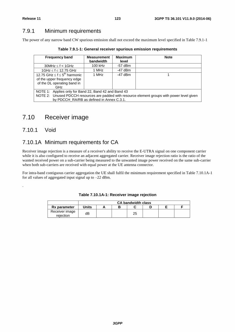
Release 11
3GPP
3GPP TS 36.101 V11.9.0 (2014-06) 123
7.9.1 Minimum requirements
The power of any narrow band CW spurious emission shall not exceed the maximum level specified in Table 7.9.1-1
Table 7.9.1-1: General receiver spurious emission requirements
Frequency band Measurement bandwidth
Maximum level
Note
30MHz f < 1GHz 100 kHz -57 dBm
1GHz f 12.75 GHz 1 MHz -47 dBm
12.75 GHz f 5th harmonic
of the upper frequency edge of the DL operating band in
GHz
1 MHz -47 dBm 1
NOTE 1: Applies only for Band 22, Band 42 and Band 43 NOTE 2: Unused PDCCH resources are padded with resource element groups with power level given
by PDCCH_RA/RB as defined in Annex C.3.1.
7.10 Receiver image
7.10.1 Void
7.10.1A Minimum requirements for CA
Receiver image rejection is a measure of a receiver's ability to receive the E-UTRA signal on one component carrier
while it is also configured to receive an adjacent aggregated carrier. Receiver image rejection ratio is the ratio of the
wanted received power on a sub-carrier being measured to the unwanted image power received on the same sub-carrier
when both sub-carriers are received with equal power at the UE antenna connector.
For intra-band contiguous carrier aggregation the UE shall fulfil the minimum requirement specified in Table 7.10.1A-1
for all values of aggregated input signal up to –22 dBm.
.
Table 7.10.1A-1: Receiver image rejection
CA bandwidth class
Rx parameter Units A B C D E F
Receiver image rejection
dB 25