3GPP TS 25 - ARIB · 3GPP TS 25.319 V10.6.0 (2011-09) Technical Specification 3rd Generation...
81
3GPP TS 25.319 V10.6.0 (2011-09) Technical Specification 3 rd Generation Partnership Project; Technical Specification Group Radio Access Network; Enhanced uplink; Overall description; Stage 2 (Release 10) The present document has been developed within the 3 rd Generation Partnership Project (3GPP TM ) and may be further elaborated for the purposes of 3GPP. The present document has not been subject to any approval process by the 3GPP Organizational Partners and shall not be implemented. This Specification is provided for future development work within 3GPP only. The Organizational Partners accept no liability for any use of this Specification. Specifications and reports for implementation of the 3GPP TM system should be obtained via the 3GPP Organizational Partners' Publications Offices.
Transcript of 3GPP TS 25 - ARIB · 3GPP TS 25.319 V10.6.0 (2011-09) Technical Specification 3rd Generation...
3GPP TS 25.319 V10.6.0 (2011-09) Technical Specification
3rd
Generation Partnership Project; Technical Specification Group Radio Access Network;
Enhanced uplink; Overall description;
Stage 2 (Release 10)
The present document has been developed within the 3rd Generation Partnership Project (3GPP TM) and may be further elaborated for the purposes of 3GPP. The present document has not been subject to any approval process by the 3GPP Organizational Partners and shall not be implemented.
This Specification is provided for future development work within 3GPP only. The Organizational Partners accept no liability for any use of this Specification.
Specifications and reports for implementation of the 3GPP TM system should be obtained via the 3GPP Organizational Partners' Publications Offices.
3GPP
3GPP TS 25.319 V10.6.0 (2011-09) 2 Release 10
Keywords
UMTS, data, stage 2
3GPP
Postal address
3GPP support office address
650 Route des Lucioles – Sophia Antipolis Valbonne - France
Tel.: +33 4 92 94 42 00 Fax: +33 4 93 65 47 16
Internet
http://www.3gpp.org
Copyright Notification
No part may be reproduced except as authorized by written permission.
The copyright and the foregoing restriction extend to reproduction in all media.
© 2011, 3GPP Organizational Partners (ARIB, ATIS, CCSA, ETSI, TTA, TTC).
All rights reserved.
UMTS™ is a Trade Mark of ETSI registered for the benefit of its members
3GPP™ is a Trade Mark of ETSI registered for the benefit of its Members and of the 3GPP Organizational Partners
LTE™ is a Trade Mark of ETSI currently being registered for the benefit of its Members and of the 3GPP Organizational
Partners
GSM® and the GSM logo are registered and owned by the GSM Association

3GPP
3GPP TS 25.319 V10.6.0 (2011-09) 3 Release 10
Contents
Foreword ............................................................................................................................................................ 5
1 Scope ........................................................................................................................................................ 6
2 References ................................................................................................................................................ 6
3 Definitions and abbreviations .................................................................................................................. 7 3.1 Definitions .......................................................................................................................................................... 7 3.1.1 General ......................................................................................................................................................... 7 3.1.2 FDD .............................................................................................................................................................. 7 3.1.3 TDD .............................................................................................................................................................. 8 3.2 Abbreviations ..................................................................................................................................................... 8
4 Background and introduction ................................................................................................................... 9
5 Requirements ........................................................................................................................................... 9
6 Overall architecture of enhanced uplink DCH ....................................................................................... 10 6.1 Protocol architecture ........................................................................................................................................ 10 6.2 Transport channel attributes ............................................................................................................................. 12 6.3 Basic physical structure .................................................................................................................................... 13 6.3.1 UL Physical layer model ............................................................................................................................ 13 6.3.1.1 FDD ...................................................................................................................................................... 13 6.3.1.2 TDD ...................................................................................................................................................... 13 6.3.2 DL Physical layer model ............................................................................................................................ 16 6.3.2.1 FDD ...................................................................................................................................................... 16 6.3.2.2 3.84 Mcps and 7.68 Mcps TDD ............................................................................................................ 18 6.3.2.3 1.28 Mcps TDD .................................................................................................................................... 18
7 MAC architecture ................................................................................................................................... 21 7.1 General Principle .............................................................................................................................................. 21 7.1.1 MAC multiplexing ...................................................................................................................................... 21 7.1.2 Reordering entity ........................................................................................................................................ 22 7.2 MAC architecture – UE side ............................................................................................................................ 22 7.2.1 Overall architecture .................................................................................................................................... 22 7.2.2 Details of MAC-d ....................................................................................................................................... 25 7.2.3 Details of MAC-c/sh ................................................................................................................................... 26 7.2.4 Details of MAC-hs ..................................................................................................................................... 27 7.2.5 Details of MAC-es/MAC-e ........................................................................................................................ 27 7.2.6 Details of MAC-is/MAC-i .......................................................................................................................... 28 7.3 MAC architecture – UTRAN side .................................................................................................................... 32 7.3.1 Overall architecture .................................................................................................................................... 32 7.3.2 Details of MAC-d ....................................................................................................................................... 35 7.3.3 Details of MAC-c/sh ................................................................................................................................... 36 7.3.4 Details of MAC-hs ..................................................................................................................................... 37 7.3.5 Details of MAC-es ...................................................................................................................................... 37 7.3.6 Details of MAC-e ....................................................................................................................................... 39 7.3.7 Details of MAC-is ...................................................................................................................................... 40 7.3.8 Details of MAC-i ........................................................................................................................................ 45
8 HARQ protocol ...................................................................................................................................... 47 8.1 General principle .............................................................................................................................................. 47 8.2 Error handling .................................................................................................................................................. 49 8.3 Signalling ......................................................................................................................................................... 49 8.3.1 Uplink ......................................................................................................................................................... 49 8.3.2 Downlink .................................................................................................................................................... 50
9 Node B controlled scheduling ................................................................................................................ 50 9.1 General principle .............................................................................................................................................. 50 9.2 UE scheduling operation .................................................................................................................................. 52
3GPP
3GPP TS 25.319 V10.6.0 (2011-09) 4 Release 10
9.2.1 Grants from the Serving RLS ..................................................................................................................... 52 9.2.1.1 FDD ...................................................................................................................................................... 52 9.2.1.2 TDD ...................................................................................................................................................... 54 9.2.2 Grants from the Non-serving RL (FDD only) ............................................................................................ 55 9.2.3 Reception of Grants from both the Serving RLS and Non-serving RL(s) (FDD only) .............................. 55 9.3 Signalling ......................................................................................................................................................... 55 9.3.1 Uplink ......................................................................................................................................................... 55 9.3.1.1 Scheduling information ......................................................................................................................... 55 9.3.1.1.1 Content ............................................................................................................................................ 55 9.3.1.1.2 Triggers ........................................................................................................................................... 56 9.3.1.1.3 Transmission and Reliability scheme .............................................................................................. 57 9.3.1.2 Happy bit of E-DPCCH (FDD only) ..................................................................................................... 59 9.3.2 Downlink .................................................................................................................................................... 59
10 Non-scheduled transmissions ................................................................................................................. 59
11 QoS control ............................................................................................................................................ 60 11.1 General Principle .............................................................................................................................................. 60 11.1.1 QoS configuration principles ...................................................................................................................... 61 11.2 TFC and E-TFC selection ................................................................................................................................ 62 11.3 Setting of Power offset attributes of MAC-d flows .......................................................................................... 64
12 Signalling parameters ............................................................................................................................. 64 12.1 Uplink signalling parameters ........................................................................................................................... 64 12.2 Downlink signalling parameters ....................................................................................................................... 64
13 Mobility procedures ............................................................................................................................... 68 13.1 Change of serving cell and/or serving RLS ...................................................................................................... 68
14 Resource management ........................................................................................................................... 68 14.1 Scheduler control from CRNC to Node B (FDD only) .................................................................................... 69 14.2 Node B to CRNC reporting (FDD only) .......................................................................................................... 69 14.3 Void.................................................................................................................................................................. 69
15 Timing Advance and Synchronisation (3.84/7.68 Mcps TDD only) ..................................................... 70
16 E-DCH transmission in CELL_FACH state and Idle Mode (FDD only) .............................................. 70
17 E-DCH semi-persistent scheduling transmission in 1.28Mcps TDD ..................................................... 71 17.1 Assignment/reassignment of semi-persistent E-PUCH resources for E-DCH semi-persistent
scheduling transmission ................................................................................................................................... 72
18 E-DCH transmission in CELL_FACH state and Idle Mode (1.28Mcps TDD only) ............................. 72
19 Dual Cell E-DCH operation (FDD only) ............................................................................................... 73 19.1 Deactivation/activation of secondary RL using HS-SCCH orders ................................................................... 75
20 Multi-Carrier E-DCH operation (1.28 Mcps TDD only) ....................................................................... 77
21 MU-MIMO operation in HSUPA channel in 1.28Mcps TDD ............................................................... 79
Annex A (informative): Change history ............................................................................................... 80

3GPP
3GPP TS 25.319 V10.6.0 (2011-09) 5 Release 10
Foreword
This Technical Specification has been produced by the 3rd
Generation Partnership Project (3GPP).
The contents of the present document are subject to continuing work within the TSG and may change following
formal TSG approval. Should the TSG modify the contents of the present document, it will be re-released by the
TSG with an identifying change of release date and an increase in version number as follows:
Version x.y.z
where:
x the first digit:
1 presented to TSG for information;
2 presented to TSG for approval;
3 or greater indicates TSG approved document under change control.
y the second digit is incremented for all changes of substance, i.e. technical enhancements, corrections,
updates, etc.
z the third digit is incremented when editorial only changes have been incorporated in the document.

3GPP
3GPP TS 25.319 V10.6.0 (2011-09) 6 Release 10
1 Scope
The present document is a technical specification of the overall support of FDD, TDD Enhanced Uplink in UTRA.
2 References
The following documents contain provisions which, through reference in this text, constitute provisions of the
present document.
References are either specific (identified by date of publication, edition number, version number, etc.) or
non-specific.
For a specific reference, subsequent revisions do not apply.
For a non-specific reference, the latest version applies. In the case of a reference to a 3GPP document
(including a GSM document), a non-specific reference implicitly refers to the latest version of that document
in the same Release as the present document.
[1] 3GPP TR 25.896: "Feasibility Study for Enhanced Uplink for UTRA FDD".
[2] 3GPP TR 21.905: "Vocabulary for 3GPP Specifications".
[3] 3GPP TS 25.214: "Physical layer procedures (FDD)".
[4] 3GPP TS 25.321: "Medium Access Control (MAC) protocol specification".
[5] 3GPP TS 25.427: "UTRAN Iub/Iur interface user plane protocol for DCH data streams"
[6] 3GPP TS 25.212: "Multiplexing and channel coding (FDD)".
[7] 3GPP TS 25.215: "Physical layer - Measurements (FDD)".
[8] 3GPP TS 25.306: "UE Radio Access capabilities".
[9] 3GPP TR 25.804: "Feasibility Study on Uplink Enhancements for UTRA TDD"
[10] 3GPP TR 25.224: "Physical layer procedures (TDD)"
[11] 3GPP TS 25.225: "Physical layer – Measurements (TDD)"
[12] 3GPP TR 25.826: "3.84 Mcps TDD Enhanced Uplink: Physical Layer Aspects"
[13] 3GPP TS 25.221: "Physical Channels and Mapping of Transport Channels onto Physical
Channeals (TDD)"
[14] 3GPP TR 25.827: "1.28 Mcps TDD Enhanced Uplink: Physical Layer Aspects"
[15] 3GPP TS 25.222: "Multiplexing and channel coding (TDD)".
[16] 3GPP TS 25.308: "High Speed Downlink Packet Access (HSDPA); Overall description; Stage
2".
3GPP
3GPP TS 25.319 V10.6.0 (2011-09) 7 Release 10
3 Definitions and abbreviations
3.1 Definitions
For the purposes of the present document, the terms and definitions given in 3GPP TR 21.905 [2] and the following
apply:
3.1.1 General
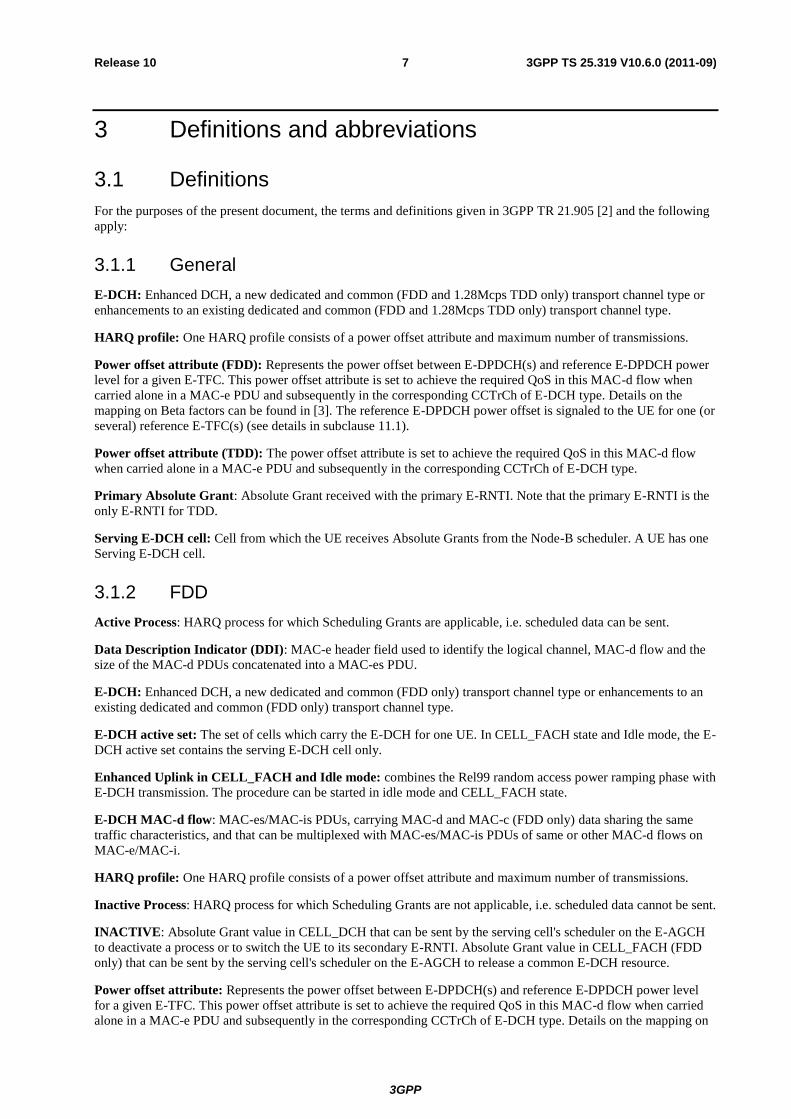
E-DCH: Enhanced DCH, a new dedicated and common (FDD and 1.28Mcps TDD only) transport channel type or
enhancements to an existing dedicated and common (FDD and 1.28Mcps TDD only) transport channel type.
HARQ profile: One HARQ profile consists of a power offset attribute and maximum number of transmissions.
Power offset attribute (FDD): Represents the power offset between E-DPDCH(s) and reference E-DPDCH power
level for a given E-TFC. This power offset attribute is set to achieve the required QoS in this MAC-d flow when
carried alone in a MAC-e PDU and subsequently in the corresponding CCTrCh of E-DCH type. Details on the
mapping on Beta factors can be found in [3]. The reference E-DPDCH power offset is signaled to the UE for one (or
several) reference E-TFC(s) (see details in subclause 11.1).
Power offset attribute (TDD): The power offset attribute is set to achieve the required QoS in this MAC-d flow
when carried alone in a MAC-e PDU and subsequently in the corresponding CCTrCh of E-DCH type.
Primary Absolute Grant: Absolute Grant received with the primary E-RNTI. Note that the primary E-RNTI is the
only E-RNTI for TDD.
Serving E-DCH cell: Cell from which the UE receives Absolute Grants from the Node-B scheduler. A UE has one
Serving E-DCH cell.
3.1.2 FDD
Active Process: HARQ process for which Scheduling Grants are applicable, i.e. scheduled data can be sent.
Data Description Indicator (DDI): MAC-e header field used to identify the logical channel, MAC-d flow and the
size of the MAC-d PDUs concatenated into a MAC-es PDU.
E-DCH: Enhanced DCH, a new dedicated and common (FDD only) transport channel type or enhancements to an
existing dedicated and common (FDD only) transport channel type.
E-DCH active set: The set of cells which carry the E-DCH for one UE. In CELL_FACH state and Idle mode, the E-
DCH active set contains the serving E-DCH cell only.
Enhanced Uplink in CELL_FACH and Idle mode: combines the Rel99 random access power ramping phase with
E-DCH transmission. The procedure can be started in idle mode and CELL_FACH state.
E-DCH MAC-d flow: MAC-es/MAC-is PDUs, carrying MAC-d and MAC-c (FDD only) data sharing the same
traffic characteristics, and that can be multiplexed with MAC-es/MAC-is PDUs of same or other MAC-d flows on
MAC-e/MAC-i.
HARQ profile: One HARQ profile consists of a power offset attribute and maximum number of transmissions.
Inactive Process: HARQ process for which Scheduling Grants are not applicable, i.e. scheduled data cannot be sent.
INACTIVE: Absolute Grant value in CELL_DCH that can be sent by the serving cell's scheduler on the E-AGCH
to deactivate a process or to switch the UE to its secondary E-RNTI. Absolute Grant value in CELL_FACH (FDD
only) that can be sent by the serving cell's scheduler on the E-AGCH to release a common E-DCH resource.
Power offset attribute: Represents the power offset between E-DPDCH(s) and reference E-DPDCH power level
for a given E-TFC. This power offset attribute is set to achieve the required QoS in this MAC-d flow when carried
alone in a MAC-e PDU and subsequently in the corresponding CCTrCh of E-DCH type. Details on the mapping on

3GPP
3GPP TS 25.319 V10.6.0 (2011-09) 8 Release 10
Beta factors can be found in [3]. The reference E-DPDCH power offset is signaled to the UE for one (or several)
reference E-TFC(s) (see details in subclause 11.1).
Primary Absolute Grant: Absolute Grant received with the primary E-RNTI.
Secondary Absolute Grant: Absolute Grant received with the secondary E-RNTI.
Secondary E-DCH Active Set: The set of cells on the secondary downlink frequency where E-DCH is carried for
one UE. Only radio links for which an E-HICH configuration is stored are considered part of the secondary E-DCH
active set.
Secondary Serving E-DCH cell: Cell from which the UE receives Absolute Grants from the Node-B scheduler on
the secondary downlink frequency. A UE has one Serving E-DCH cell on the secondary uplink frequency.
Secondary Serving E-DCH RLS or Secondary Serving RLS: In Dual Cell E-DCH operation, the set of cells
which contains at least the Secondary Serving E-DCH cell and from which the UE can receive and combine one
Relative Grant. A UE can have zero or one Secondary Serving E-DCH RLS.
Secondary Non-serving E-DCH RL or Secondary Non-serving RL: In Dual Cell E-DCH operation, the cell
which belongs to the Secondary E-DCH active set but does not belong to the Secondary Serving E-DCH RLS and
from which the UE in CELL_DCH can receive one Relative Grant. The UE can have zero, one or several Secondary
Non-serving E-DCH RL(s).
Activated uplink frequency: For a specific UE, an uplink frequency is said to be activated if the UE is allowed to
transmit on that frequency. The primary uplink frequency is always activated when configured while a secondary
uplink frequency can be activated and de-activated by means of an HS-SCCH order.
Configured uplink frequency: For a specific UE, an uplink frequency is said to be configured if the UE has
received all relevant information from higher layers in order to perform transmission on that frequency.
Primary uplink frequency: If a single uplink frequency is configured for the UE, then it is the primary uplink
frequency. In case more than one uplink frequencies are configured for the UE, then the primary uplink frequency is
the frequency on which the E-DCH corresponding to the serving E-DCH cell associated with the serving HS-DSCH
cell is transmitted. The association between a pair of uplink and downlink frequencies is indicated by higher layers.
Secondary uplink frequency: A secondary uplink frequency is a frequency on which an E-DCH corresponding to a
serving E-DCH cell associated with a secondary serving HS-DSCH cell is transmitted. The association between a
pair of uplink and downlink frequencies is indicated by higher layers.
Serving E-DCH RLS or Serving RLS: Set of cells which contains at least the Serving E-DCH cell and from which
the UE can receive and combine one Relative Grant. The UE has only one Serving E-DCH RLS. In CELL_FACH
state and Idle mode, the Serving E-DCH RLS or Serving RLS contains the Serving E-DCH cell only, from which
the UE can receive the Relative Grant.
Non-serving E-DCH RL or Non-serving RL: Cell which belongs to the E-DCH active set but does not belong to
the Serving E-DCH RLS and from which the UE in CELL_DCH can receive one Relative Grant. The UE can have
zero, one or several Non-serving E-DCH RL(s).
Common E-DCH resource: Common E-DCH resources are under direct control of the Node B and are shared by
UEs in CELL_FACH and IDLE mode. The RNC is not involved in the assignment of these resources to UEs. Since
only one cell is involved in the resource allocation, soft handover is not possible.
3.1.3 TDD
Enhanced Uplink in CELL_FACH and Idle mode (1.28Mcps TDD only): in 1.28Mcps TDD, the REL7
enhanced random access procedure for E-DCH is used in idle mode and CELL_FACH state.
Common E-DCH resource (1.28Mcps TDD only): common E-DCH resource are used by UEs in CELL_FACH
and IDLE mode under direct control of Node B and are shared between UEs using E-DCH transmission in
CELL_FACH, Idle mode and CELL_DCH.
3.2 Abbreviations

3GPP
3GPP TS 25.319 V10.6.0 (2011-09) 9 Release 10
For the purposes of the present document, the abbreviations given in 3GPP TR 21.905 [2] and the following apply:
AG Absolute Grant
E-AGCH E-DCH Absolute Grant Channel
E-DPCCH E-DCH Dedicated Physical Control Channel (FDD only)
E-DPDCH E-DCH Dedicated Physical Data Channel (FDD only)
E-HICH E-DCH HARQ Acknowledgement Indicator Channel
E-PUCH Enhanced Uplink Physical Channel (TDD only)
E-RGCH E-DCH Relative Grant Channel
E-RUCCH E-DCH Random Access Uplink Control Channel (TDD only)
E-RNTI E-DCH Radio Network Temporary Identifier
E-TFC E-DCH Transport Format Combination
E-UCCH E-DCH Uplink Control Channel (TDD only)
HARQ Hybrid Automatic Repeat Request
HSDPA High Speed Downlink Packet Access
MC-HSUPA Multi-Carrier HSUPA
MU-MIMO Multi-User Multiple Input Multiple Output
RG Relative Grant
RLS Radio Link Set
RSN Retransmission Sequence Number
SG Serving Grant
TSN Transmission Sequence Number
4 Background and introduction
The technical purpose of the Enhanced Uplink feature is to improve the performance of uplink dedicated and
common (FDD and 1.28Mcps TDD only) transport channels, i.e. to increase capacity and throughput and reduce
delay. This is applicable for UTRA TDD and FDD.
The following techniques are part of the Enhanced Uplink feature:
- Node B controlled scheduling: possibility for the Node B to control, within the limits set by the RNC, the set
of TFCs from which the UE may choose a suitable TFC.
- Node B controlled physical resource scheduling (TDD ony).
- Hybrid ARQ: rapid retransmissions of erroneously received data packets between UE and Node B.
- Higher order modulation (16QAM) (TDD and FDD).
- Intra-frame code hopping (3.84 Mcps and 7.68 Mcps TDD only).
- Shorter TTI: possibility of introducing a 2 ms TTI (FDD only).
- Enhanced Uplink in CELL_FACH state and Idle mode (FDD and 1.28Mcps TDD only).
- Dual Cell E-DCH (FDD).
- Multi-Carrier E-DCH (1.28 Mcps TDD only).
5 Requirements
- The Enhanced Uplink feature shall aim at providing significant enhancements in terms of user experience
(throughput and delay) and/or capacity. The coverage is an important aspect of the user experience and that it
is desirable to allow an operator to provide for consistency of performance across the whole cell area.
- The focus shall be on urban, sub-urban and rural deployment scenarios.
- Full mobility shall be supported, i.e., mobility should be supported for high-speed cases also, but
optimisation should be for low-speed to medium-speed scenarios.

3GPP
3GPP TS 25.319 V10.6.0 (2011-09) 10 Release 10
- Improvements in the uplink performance of dedicated transport channels are required, with priority given to
improving performance with respect to streaming, interactive and background services. Relevant QoS
mechanisms shall allow the support of streaming, interactive and background PS services.
- It is highly desirable to keep the Enhanced Uplink as simple as possible. New techniques or group of
techniques shall therefore provide significant incremental gain for an acceptable complexity. The value added
per feature/technique should be considered in the evaluation. It is also desirable to avoid unnecessary options
in the specification of the feature.
- The UE and network complexity shall be minimised for a given level of system performance.
- The impact on current releases in terms of both protocol and hardware perspectives shall be taken into
account.
- It shall be possible to introduce the Enhanced Uplink feature in a network which has terminals from
Release'99, Release 4 and Release 5. The Enhanced Uplink feature shall enable to achieve significant
improvements in overall system performance when operated together with HSDPA. Emphasis shall be given
on the potential impact the new feature may have on the downlink capacity. Likewise it shall be possible to
deploy the Enhanced Uplink feature without any dependency on the deployment of the HSDPA feature.
However, a terminal supporting the Enhanced Uplink feature shall support HSDPA.
- Commonality between TDD and FDD E-DCH features is desired as long as system performance is not
impaired.
- For TDD, it shall be possible to run enhanced uplink in parallel with HS-DSCH without associated (or
otherwise) uplink or downlink dedicated physical channels.
- For FDD, it shall be possible to combine the REL99 random access signature transmission and power
ramping phase with E-DCH transmission, called Enhanced Uplink in CELL_FACH and Idle mode.
Improvements in the uplink performance of dedicated and common transport channels in Idle and Connected
mode are required.
- For 1.28Mcps TDD, it shall be possible to run enhanced uplink in CELL_FACH and Idle state, called
Enhanced Uplink in CELL_FACH and Idle state.
- For FDD, it shall be possible to have simultaneous transmission of two E-DCH transport channels when Dual
Cell HSDPA operation on a single frequency band is configured, called Dual Cell E-DCH operation.
- For 1.28 Mcps TDD, it shall be possible to have simultaneous transmission of multiple E-DCH transport
channels on a single frequency band, called Multi-Carrier E-DCH operation, with the characteristic that the
E-DCH associated channels (including control channel and traffic channel) are allocated on more than one
carriers.
6 Overall architecture of enhanced uplink DCH
6.1 Protocol architecture
The following modifications to the existing nodes are needed to support enhanced uplink DCH and Enhanced
Uplink in CELL_FACH state (FDD and 1.28Mcps TDD only) and Idle mode (FDD and 1.28Mcps TDD only):
UE
New MAC entities (MAC-es/MAC-e and MAC-is/i) are added in the UE below MAC-d. MAC- es/MAC-e or MAC-
is/i in the UE handle HARQ retransmissions, scheduling and MAC-e/i multiplexing, E-DCH TFC selection.
Node B
New MAC entities (MAC-e and MAC-i) are added in the Node B to handle HARQ retransmissions, scheduling and
MAC-e / MAC-i demultiplexing.
3GPP
3GPP TS 25.319 V10.6.0 (2011-09) 11 Release 10
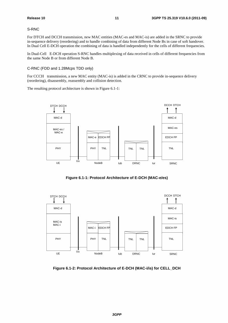
S-RNC
For DTCH and DCCH transmission, new MAC entities (MAC-es and MAC-is) are added in the SRNC to provide
in-sequence delivery (reordering) and to handle combining of data from different Node Bs in case of soft handover.
In Dual Cell E-DCH operation the combining of data is handled independently for the cells of different frequencies.
In Dual-Cell E-DCH operation S-RNC handles multiplexing of data received in cells of different frequencies from
the same Node B or from different Node B.
C-RNC (FDD and 1.28Mcps TDD only)
For CCCH transmission, a new MAC entity (MAC-is) is added in the CRNC to provide in-sequence delivery
(reordering), disassembly, reassembly and collision detection.
The resulting protocol architecture is shown in Figure 6.1-1:
PHY PHY
EDCH FP EDCH FP
Iub UE NodeB Uu
DCCH DTCH
TNL TNL
DTCH DCCH
MAC-e
SRNC
MAC-d
MAC-e
MAC-d
MAC-es / MAC-e
MAC-es
Iur
TNL TNL
DRNC
Figure 6.1-1: Protocol Architecture of E-DCH (MAC-e/es)
PHY PHY
EDCH FP EDCH FP
Iub UE NodeB Uu
DCCH DTCH
TNL TNL
DTCH DCCH
SRNC
MAC-d
MAC-i
MAC - d
MAC-is
Iur
TNL TNL
D RNC
MAC-is MAC-i
Figure 6.1-2: Protocol Architecture of E-DCH (MAC-i/is) for CELL_DCH

3GPP
3GPP TS 25.319 V10.6.0 (2011-09) 12 Release 10
PHY PHY
EDCH FP EDCH FP
Iub UE NodeB Uu
DCCH DTCH
TNL TNL
DTCH DCCH
SRNC
MAC - d
MAC - i
MAC - d
MAC - is
Iur
TNL TNL
D RNC
MAC - is
MAC - i EDCH FP EDCH FP
Figure 6.1-3: Protocol Architecture of E-DCH (MAC-i/is) for DTCH/DCCH transmission in CELL_FACH
PHY PHY
EDCH FP EDCH FP
IubUE NodeBUu
TNL TNL
CRNC
MAC-c
MAC-i
MAC-c
MAC-is
MAC-isMAC-i
CCCHCCCH
Figure 6.1-4: Protocol Architecture of E-DCH (MAC-i/is) for CCCH transmission
6.2 Transport channel attributes
The E-DCH transport channel has the following characteristics:
- E-DCH and DCH use separate CCTrCHs
- There is only one CCTrCH of E-DCH type per UE per Activated Uplink Frequency;
- There is only one E-DCH per CCTrCH of E-DCH type;
- There is only one transport block per TTI per E-DCH transport channel;
- Both 2 ms TTI and 10 ms TTI are supported by FDD E-DCH. Only a 5 ms TTI is supported by 1.28 Mcps
TDD E-DCH. Only a 10 ms TTI is supported by 3.84 Mcps and 7.68 Mcps TDD E-DCH.
- For FDD:
The support of 10 ms TTI is mandatory for all UEs. The support of the 2 ms TTI by the UE is only
mandatory for certain UE categories. Switching between the two TTIs can be performed by UTRAN
through L3 signalling;

3GPP
3GPP TS 25.319 V10.6.0 (2011-09) 13 Release 10
- For all UE categories, the uplink DCH capability is limited to 64kbps when E-DCH is configured for the
radio link (see [8]).
- CRC size = 24 bits;
- channel coding = turbo 1/3;
- redundancy version: always use RV index 0, or use table defined in [6] for FDD and in [15] for TDD.
6.3 Basic physical structure
6.3.1 UL Physical layer model
6.3.1.1 FDD
E-DCH model with DCH and HS-DSCH
Coded Composite Transport Channel
CCTrCH)
Phy CH Phy CH
TPC & TFCI
(
Physical Channel Data Streams
Demultiplexing
/Splitting
DCH
Coding and multiplexing
Phy CH
DCH
.....
.....
Phy CH
ACK/NACK
CQI Physical Channel Data Streams
Demultiplexing
/Splitting
E-DCH
Coding and multiplexing
Phy CH
.....
Coded Composite Transport Channel
CCTrCH)
Phy CH
E-DCH TFCI
E-DCH HARQ
Phy CH
Figure 6.3.1.1-1: Model of the UE's Uplink physical layer
There is only one E-DCH per CCTrCh of E-DCH type.
For both 2 ms and 10 ms TTI, the information carried on the E-DPCCH consists of 10 bits in total: the E-TFCI (7
bits), the RSN (2 bits) and the 'happy' bit (see in subclause 9.3.1.2).
The E-DPCCH is sent with a power offset relative to the DPCCH. The power offset is signalled by RRC.
If E-DCH is used in CELL_FACH state and Idle mode, then no parallel DCH transmission is supported.
The network is able to configure with the system information whether the UE transmits HS-DPCCH after collision
resolution in the CELL_FACH state when it has E-DCH resources allocated. If the UE is transmitting CCCH HS-
DPCCH is not transmitted.
6.3.1.2 TDD
E-DCH model with HS-DSCH

3GPP
3GPP TS 25.319 V10.6.0 (2011-09) 14 Release 10
E-DCH
(CCTrCH)
Coded Composite
Transport Channel
E-UCCH
TPC
Phy CH
ACK/NACK
CQI
TPC
Physical Channel Data Streams
Demultiplexing
/Splitting
Coding and multiplexing
Phy CH
.....
Phy CH Phy CH
E-RUCCH
Figure 6.3.1.2-1: Model of the UE's Uplink physical layer
E-DCH model with DCH and HS-DSCH
E-UCCH
TPC Demultiplexing
/Splitting
Coding and multiplexing
Phy CH
E-DCH
.....
Coded Composite
Transport Channel
(CCTrCH)
Phy CH
ACK/NACK
CQI
TPC
Demultiplexing/
Splitting
Coded Composite Transport Channel
(CCTrCH)
TPC & TFCI
Phy CH
....
Coding and
multiplexin
g
DCH DCH
Phy CH Phy CH
Physical Channel
Data Steams
E-RUCCH
Phy CH
Figure 6.3.1.2-2: Model of the UE's Uplink physical layer (E-DCH with DCH and HS-DSCH)
E-DCH model with HS-DSCH

3GPP
3GPP TS 25.319 V10.6.0 (2011-09) 15 Release 10
Coding and
multiplexing
Demultiplexing
/SplittingE-UCCH
TPCE-RUCCH
Physical Channel
Data Stream
Coded
Composite
Transport
Channel
( CCTrCH)
Carrier 1
assosiciated
ACK/NACK
CQI
TPC
Phy
CH
Phy
CH
…… Phy
CH
Phy
CH
……Phy
CH
E-DCH(Carrier 1)
Carrier m
assosiciated
ACK/NACK
CQI
TPC
Coding and
multiplexing
Demultiplexing
/SplittingE-UCCH
TPC
Coded
Composite
Transport
Channel
( CCTrCH)
Phy
CH
Phy
CH
……
E-DCH(Carrier n)
……
Figure 6.3.1.2-3: Model of the UE's Uplink physical layer (1.28 Mcps TDD multi-carrier E-DCH operation mode only)
E-DCH model with DCH
Coding and
multiplexing
Demultiplexing
/SplittingE-UCCH
TPCE-RUCCH
Physical Channel
Data Stream
Coded
Composite
Transport
Channel
( CCTrCH)
Phy
CH
Phy
CH
……Phy
CH
E-DCH(Carrier 1)
Coding and
multiplexing
Demultiplexing
/SplittingE-UCCH
TPC
Coded
Composite
Transport
Channel
( CCTrCH)
Phy
CH
Phy
CH
……
E-DCH(Carrier n)
Phy CHPhy CH
Coding and
multiplexing
Coded
Composite
Transport
Channel
( CCTrCH) MUX
Physical Channel
Data Streams
DCH DCH
TPC
&TFCI
……
Figure 6.3.1.2-4: Model of the UE's Uplink physical layer (1.28 Mcps TDD multi-carrier E-DCH operation mode only)
E-DCH model with DCH and HS-DSCH
Coding and
multiplexing
Demultiplexing
/SplittingE-UCCH
TPCE-RUCCH
Physical Channel
Data Stream
Coded
Composite
Transport
Channel
( CCTrCH)
Carrier 1
assosiciated
ACK/NACK
CQI
TPC
Phy
CH
Phy
CH
…… Phy
CH
Phy
CH
……Phy
CH
E-DCH(Carrier 1)
Coding and
multiplexing
Demultiplexing
/SplittingE-UCCH
TPC
Coded
Composite
Transport
Channel
( CCTrCH)
Phy
CH
Phy
CH
……
E-DCH(Carrier n)
Phy CHPhy CH
Coding and
multiplexing
Coded
Composite
Transport
Channel
( CCTrCH) MUX
Physical Channel
Data Streams
DCH DCH
TPC
&TFCI
Carrier m
assosiciated
ACK/NACK
CQI
TPC
……
Figure 6.3.1.2-5: Model of the UE's Uplink physical layer (1.28 Mcps TDD multi-carrier E-DCH operation mode only)
E-DCH model with HS-DSCH

3GPP
3GPP TS 25.319 V10.6.0 (2011-09) 16 Release 10
Carrier 1 Carrier m
(CCTrCH)
Coded Composite
Transport Channel
E- UCCH
TPC
Coding and
multiplexing
Phy CH
ACK/NACK
CQI
TPC
Physical Channel
Data Streams
Demultiplexing
/Splitting
Phy CH
.....
Phy CH Phy CH
E- RUCCH
Phy CH
ACK/NACK
CQI
TPC
E- DCH
Figure 6.3.1.2-6: Model of the UE's Uplink physical layer (1.28 Mcps TDD multi-carrier HS-DSCH operation mode)
E-DCH model with DCH and HS-DSCH
E- UCCH
TPC Demultiplexing
/Splitting
Coding and multiplexing
Phy CH
E- DCH
.....
Coded Composite
Transport Channel
( CCTrCH)
Phy CH
ACK/NACK
CQI
TPC
Demultiplexing/
Splitting
Coded Composite
Transport Channel
( CCTrCH)
TPC & TFCI
Phy CH
....
Coding and
multiplexing
DCH DCH
Phy CH Phy CH
Physical Channel
Data Steams
E- RUCCH
Phy CH
ACK/NACK
CQI
TPC
Phy CH
Carrier 1 Carrier m
Figure 6.3.1.2-7: Model of the UE's Uplink physical layer (1.28 Mcps TDD multi-carrier HS-DSCH operation mode)
If E-DCH is used in CELL_FACH state and Idle mode, then no parallel DCH transmission is supported.
6.3.2 DL Physical layer model
6.3.2.1 FDD
E-DCH model with DCH and HS-DSCH
3GPP
3GPP TS 25.319 V10.6.0 (2011-09) 17 Release 10
ACK/NACK
stream 1,…m
TPC stream 1
TFCI 1
TPC stream n
TFCI n
Phy CH Phy CH
Phy CH Phy CH
.....
..... .....
Relative Grant
stream 1,…m
Cell es
Absolute Grant TFRI
HARQ
TFRI
HARQ
Cell e1
Cell em
Coded Composite
(
Phy CH Phy CH
HS-DSCH
Phy CH
Cell d1
Cell dn
Cell Hs=Cell es Phy CH Phy CH
Coded Composite Transport Channel
( CCTrCH)
Physical Channel Data Streams
MUX
DCH
Decoding and demultiplexing
Phy CH Phy CH
Phy CH Phy CH
DCH
.....
.....
.....
.....
Decoding
Transport Channel CCTrCH)
MUX
..... Data Streams Physical Channel
.....
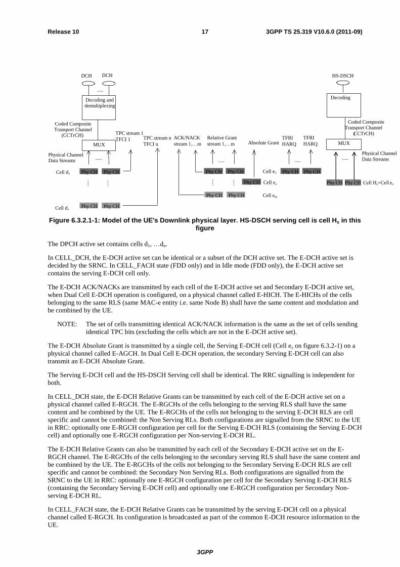
Figure 6.3.2.1-1: Model of the UE's Downlink physical layer. HS-DSCH serving cell is cell Hs in this figure
The DPCH active set contains cells d1, …dn.
In CELL_DCH, the E-DCH active set can be identical or a subset of the DCH active set. The E-DCH active set is
decided by the SRNC. In CELL_FACH state (FDD only) and in Idle mode (FDD only), the E-DCH active set
contains the serving E-DCH cell only.
The E-DCH ACK/NACKs are transmitted by each cell of the E-DCH active set and Secondary E-DCH active set,
when Dual Cell E-DCH operation is configured, on a physical channel called E-HICH. The E-HICHs of the cells
belonging to the same RLS (same MAC-e entity i.e. same Node B) shall have the same content and modulation and
be combined by the UE.
NOTE: The set of cells transmitting identical ACK/NACK information is the same as the set of cells sending
identical TPC bits (excluding the cells which are not in the E-DCH active set).
The E-DCH Absolute Grant is transmitted by a single cell, the Serving E-DCH cell (Cell es on figure 6.3.2-1) on a
physical channel called E-AGCH. In Dual Cell E-DCH operation, the secondary Serving E-DCH cell can also
transmit an E-DCH Absolute Grant.
The Serving E-DCH cell and the HS-DSCH Serving cell shall be identical. The RRC signalling is independent for
both.
In CELL_DCH state, the E-DCH Relative Grants can be transmitted by each cell of the E-DCH active set on a
physical channel called E-RGCH. The E-RGCHs of the cells belonging to the serving RLS shall have the same
content and be combined by the UE. The E-RGCHs of the cells not belonging to the serving E-DCH RLS are cell
specific and cannot be combined: the Non Serving RLs. Both configurations are signalled from the SRNC to the UE
in RRC: optionally one E-RGCH configuration per cell for the Serving E-DCH RLS (containing the Serving E-DCH
cell) and optionally one E-RGCH configuration per Non-serving E-DCH RL.
The E-DCH Relative Grants can also be transmitted by each cell of the Secondary E-DCH active set on the E-
RGCH channel. The E-RGCHs of the cells belonging to the secondary serving RLS shall have the same content and
be combined by the UE. The E-RGCHs of the cells not belonging to the Secondary Serving E-DCH RLS are cell
specific and cannot be combined: the Secondary Non Serving RLs. Both configurations are signalled from the
SRNC to the UE in RRC: optionally one E-RGCH configuration per cell for the Secondary Serving E-DCH RLS
(containing the Secondary Serving E-DCH cell) and optionally one E-RGCH configuration per Secondary Non-
serving E-DCH RL.
In CELL_FACH state, the E-DCH Relative Grants can be transmitted by the serving E-DCH cell on a physical
channel called E-RGCH. Its configuration is broadcasted as part of the common E-DCH resource information to the
UE.

3GPP
3GPP TS 25.319 V10.6.0 (2011-09) 18 Release 10
The ACK/NACKs received from UTRAN after combining (see Note above), the Absolute Grant information
received from UTRAN (from the Serving E-DCH cell), and the Relative Grants received from UTRAN (optionally
one from the Serving E-DCH RLS after combining, and optionally one from each Non-serving RL), are all sent to
MAC by L1.
If E-DCH is used in CELL_FACH state and Idle mode, then no parallel DCH transmission is supported. The DPCH
active set contains one cell only.
6.3.2.2 3.84 Mcps and 7.68 Mcps TDD
E-DCH model with HS-DSCH
E-HICH
ACK/NACK
Phy CH
Absolute Grant
Phy CH
E-AGCH
TPC
TFRI
HARQ
Phy CH
HS-DSCH
Decoding
Coded Composite
Transport Channel
(CCTRCH)
MUX
Phy CH Phy CH
HS-SCCH
Figure 6.3.2.2-1: Model of the UE's Downlink physical layer.
6.3.2.3 1.28 Mcps TDD
E-DCH model with HS-DSCH
3GPP
3GPP TS 25.319 V10.6.0 (2011-09) 19 Release 10
E-HICH
ACK/NACK
Phy CH
TPC, SS
Phy CH
E-AGCH
Phy CH Phy CH
HS-SCCH
TFRI
HARQ info
TPC, SS
.....
Absolute Grant
Coded Composite
(
HS-DSCH
Decoding
Transport Channel CCTrCH)
MUX
Phy CH Phy CH
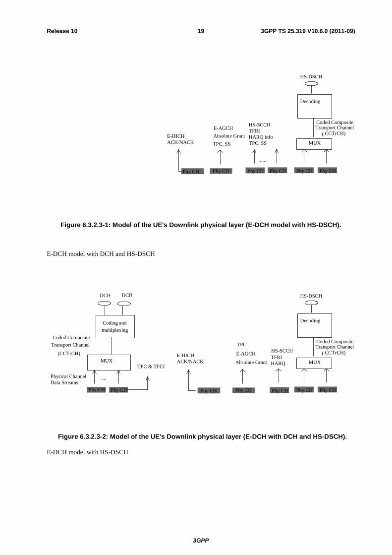
Figure 6.3.2.3-1: Model of the UE's Downlink physical layer (E-DCH model with HS-DSCH).
E-DCH model with DCH and HS-DSCH
MUX TPC & TFCI
....
Coding and
multiplexing
DCH DCH
Phy CH Phy CH
(CCTrCH)
Coded Composite
Transport Channel
Physical Channel
Data Streams
TPC
E-HICH
ACK/NACK
Phy CH
Absolute Grant
Phy CH
E-AGCH TFRI
HARQ
Coded Composite
(
Phy CH
HS-DSCH
Decoding
Transport Channel CCTrCH)
MUX
Phy CH Phy CH
HS-SCCH
Figure 6.3.2.3-2: Model of the UE's Downlink physical layer (E-DCH with DCH and HS-DSCH).
E-DCH model with HS-DSCH

3GPP
3GPP TS 25.319 V10.6.0 (2011-09) 20 Release 10
Phy CHPhy CH
Phy CHPhy CHPhy CH
HS-DSCH(Carrier 1)
Decoding
Coded Composite
Transport Channel
( CCTrCH)
MUX
Carrier 1 assosicated
HS-SCCH
TFRI
HARQ info
TPC,SS
Carrier 1 assosicated
E-AGCH
Absolute Grant
TPC,SS
Carrier 1 assosicated
E-HICH
ACK/NACK
Phy CH
……
Phy CH
……
Phy CH
……
Phy CH
……
Phy CH
Carrier n assosicated
E-HICH
ACK/NACK
Carrier n assosicated
E-AGCH
Absolute Grant
TPC,SS
Carrier m assosicated
HS-SCCH
TFRI
HARQ info
TPC,SS
……
Phy CHPhy CH
HS-DSCH(Carrier m)
Decoding
Coded Composite
Transport Channel
( CCTrCH)
MUX
……
……
Figure 6.3.2.3-3: Model of the UE's Downlink physical layer (1.28 Mcps TDD multi-carrier E-DCH operation mode only)
E-DCH model with DCH
Phy CHPhy CH
Carrier 1
assosicated
E-AGCH
Absolute Grant
TPC,SS
Carrier 1
assosicated
E-HICH
ACK/NACK
……
Phy CH
……
Phy CH
Carrier n
assosicated
E-HICH
ACK/NACK
Carrier n
assosicated
E-AGCH
Absolute Grant
TPC,SS
Phy CHPhy CH
Coding and
multiplexing
Coded
Composite
Transport
Channel
( CCTrCH) MUX
Physical Channel
Data Streams
DCH DCH
TPC
&TFCI
Figure 6.3.2.3-4: Model of the UE's Downlink physical layer (1.28 Mcps TDD multi-carrier E-DCH operation mode only)
E-DCH model with DCH and HS-DSCH
Phy CHPhy CH
Phy CHPhy CHPhy CH
HS-DSCH(Carrier 1)
Decoding
Coded
Composite
Transport
Channel
( CCTrCH)MUX
Carrier 1
assosicated
HS-SCCH
TFRI
HARQ info
TPC,SS
Carrier 1
assosicated
E-AGCH
Absolute Grant
TPC,SS
Carrier 1
assosicated
E-HICH
ACK/NACK
Phy CH
……
Phy CH
……
Phy CH
……
Phy CH
……
Phy CH
Carrier n
assosicated
E-HICH
ACK/NACK
Carrier n
assosicated
E-AGCH
Absolute Grant
TPC,SS
Carrier m
assosicated
HS-SCCH
TFRI
HARQ info
TPC,SS
……
Phy CHPhy CH
HS-DSCH(Carrier m)
Decoding
Coded
Composite
Transport
Channel
( CCTrCH)MUX
……
……
Phy CHPhy CH
Coding and
multiplexing
Coded
Composite
Transport
Channel
( CCTrCH) MUX
Physical Channel
Data Streams
DCH DCH
TPC
&TFCI
Figure 6.3.2.3-5: Model of the UE's Downlink physical layer (1.28 Mcps TDD multi-carrier E-DCH operation mode only)
E-DCH model with HS-DSCH
3GPP
3GPP TS 25.319 V10.6.0 (2011-09) 21 Release 10
E- HICH
ACK/NACK
Phy CH
Absolute Grant
TPC, SS
Phy CH
E- AGCH
HS- DSCH ( Carrier 1)
Decoding
Coded
Composite
Transport
Channel
( CCTrCH )MUX
Carrier 1 assosicated
HS- SCCH
TFRI
TPC , SS
……
……
Carrier m
assosicated
HS- SCCH
TFRI
HARQ info
TPC , SS
……
HS- DSCH ( Carrier m )
DecodingCoded
Composite
Transport
Channel
( CCTrCH )
MUX
……
……
Phy CH Phy CH Phy CH Phy CH Phy CH Phy CH
Phy CH Phy CH
HARQ info
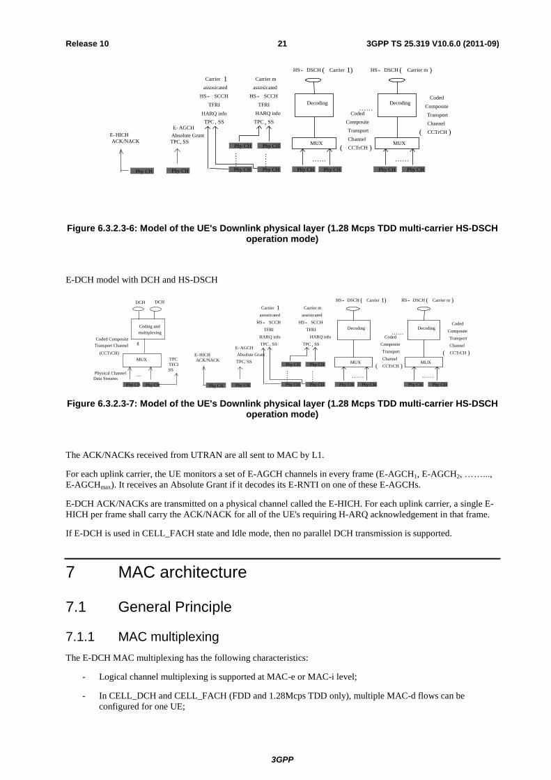
Figure 6.3.2.3-6: Model of the UE's Downlink physical layer (1.28 Mcps TDD multi-carrier HS-DSCH operation mode)
E-DCH model with DCH and HS-DSCH
MUX TPC
TFCI
SS ....
Coding and
multiplexing
g
DCH DCH
Phy CH Phy CH
(CCTrCH)
Coded Composite
Transport Channel
Physical Channel
Data Streams
E- HICH
ACK/NACK
Phy CH
TPC, SS
Phy CH
E- AGCH
Absolute Grant
HS- DSCH ( Carrier 1)
Decoding
Coded
Composite
Transport
Channel
( CCTrCH )MUX
Carrier 1 assosicated
HS- SCCH
TFRI
HARQ info
TPC , SS
……
……
Carrier m
assosicated
HS- SCCH
TFRI
HARQ info
TPC , SS
……
HS- DSCH ( Carrier m )
DecodingCoded
Composite
Transport
Channel
( CCTrCH )
MUX
……
……
Phy CH Phy CH Phy CH Phy CH Phy CH Phy CH
Phy CH Phy CH
Figure 6.3.2.3-7: Model of the UE's Downlink physical layer (1.28 Mcps TDD multi-carrier HS-DSCH operation mode)
The ACK/NACKs received from UTRAN are all sent to MAC by L1.
For each uplink carrier, the UE monitors a set of E-AGCH channels in every frame (E-AGCH1, E-AGCH2, ……...,
E-AGCHmax). It receives an Absolute Grant if it decodes its E-RNTI on one of these E-AGCHs.
E-DCH ACK/NACKs are transmitted on a physical channel called the E-HICH. For each uplink carrier, a single E-
HICH per frame shall carry the ACK/NACK for all of the UE's requiring H-ARQ acknowledgement in that frame.
If E-DCH is used in CELL_FACH state and Idle mode, then no parallel DCH transmission is supported.
7 MAC architecture
7.1 General Principle
7.1.1 MAC multiplexing
The E-DCH MAC multiplexing has the following characteristics:
- Logical channel multiplexing is supported at MAC-e or MAC-i level;
- In CELL_DCH and CELL_FACH (FDD and 1.28Mcps TDD only), multiple MAC-d flows can be
configured for one UE;

3GPP
3GPP TS 25.319 V10.6.0 (2011-09) 22 Release 10
- The multiplexing of different MAC-d flows within the same MAC-e or MAC-i PDU is supported. But not
all the combinations may be allowed for one UE. In CELL_DCH, the allowed combinations are under the
control of the SRNC (see in clause 11). In CELL_FACH (FDD and 1.28Mcps TDD only), the allowed
combinations are under the control of the CRNC (see in clause 11).
- There can be up to 8 MAC-d flows for a UE;
- Up to 15 logical channels can be multiplexed on an E-DCH transport channel.
7.1.2 Reordering entity
For DCCH and DTCH transmission, the re-ordering entity is part of a separate MAC sub-layer, MAC-es or MAC-is,
in the SRNC. Data coming from different MAC-d flows are reordered in different reordering queues. There is one
reordering queue per logical channel.
For DCCH and DTCH transmission, the reordering is based on a specific TSN included in the MAC-es or MAC-is
PDU for FDD and on Node-B tagging with a (CFN, subframe number). For each MAC-es or MAC-is PDU, the
SRNC receives the TSN originating from the UE, for FDD as well as the CFN and subframe number originating
from the Node-B to perform the re-ordering. Additional mechanisms (e.g. timer-based and/or window-based) are up
to SRNC implementation and will not be standardised. Furthermore, the reordering entity detects and removes
duplicated received MAC-es or MAC-is PDUs.
For FDD only, for CCCH transmission the re-ordering entity is part of a MAC-is in the CRNC. For each common E-
DCH resource, there is one reordering queue for the logical channel CCCH. The reordering is based on a specific
TSN included in the MAC-is PDU. Additional mechanisms are up to Node B implementation and will not be
standardised. Furthermore, the reordering entity detects and removes duplicated received MAC-is PDUs.
For 1.28Mcps TDD, when CCCH is transmitted on E-DCH, the re-ordering entity is part of a MAC-is in the CRNC.
For each UE, there is one reordering queue for the logical channel CCCH. The reordering is based on a specific TSN
included in the MAC-is PDU. Additional mechanisms are up to Node B implementation and will not be
standardized. Furthermore, the reordering entity detects and removes duplicated received MAC-is PDUs.
7.2 MAC architecture – UE side
7.2.1 Overall architecture
The overall UE MAC architecture, which is shown in Figure 7.2.1-1 and Figure 7.2.1-2, includes new MAC-
es/MAC-e and MAC-is/i entities which controls access to the E-DCH. A new connection from MAC-d to MAC-
es/MAC-e or MAC-is/i is added to the architecture, as well as a connection between MAC-es/MAC-e and the MAC
Control SAP. For FDD and 1.28Mcps TDD only, a new connection from MAC-c/sh to MAC-is/i is added to the
architecture. The higher layers configure whether MAC-es/e or MAC-i/is is used.

3GPP
3GPP TS 25.319 V10.6.0 (2011-09) 23 Release 10
Associated
Downlink
Signalling
E-DCH
MAC-d
FACH RACH
DCCH DTCH DTCH
DSCH DCH DCH
MAC Control
USCH ( TDD only )
CPCH ( FDD only )
CTCH BCCH CCCH SHCCH ( TDD only )
PCCH
PCH FACH
MAC-c/sh
USCH ( TDD only )
DSCH
MAC-hs
HS-DSCH
Associated
Uplink
Signalling
Associated
Downlink
Signalling
MAC-es /
MAC-e
Associated
Uplink
Signalling
Figure 7.2.1-1: UE side MAC architecture with MAC-e and MAC-es
Associated
Downlink
Signalling
E -DCH
MAC -d
FACH RACH
DCCH DTCHDTCH
DSCH DCH DCH
MAC Control
USCH ( TDD only )
CPCH ( FDD only )
CTCHBCCH CCCH SHCCH( TDD only )
PCCH
PCH FACH
MAC -c/sh
USCH ( TDD only )
DSCH
MAC -hs
HS -DSCH
Associated
Uplink
Signalling
Associated
Downlink
Signalling
MAC -is /
MAC -i
Associated
Uplink
Signalling
Figure 7.2.1-2: UE side MAC architecture with MAC-i and MAC-is
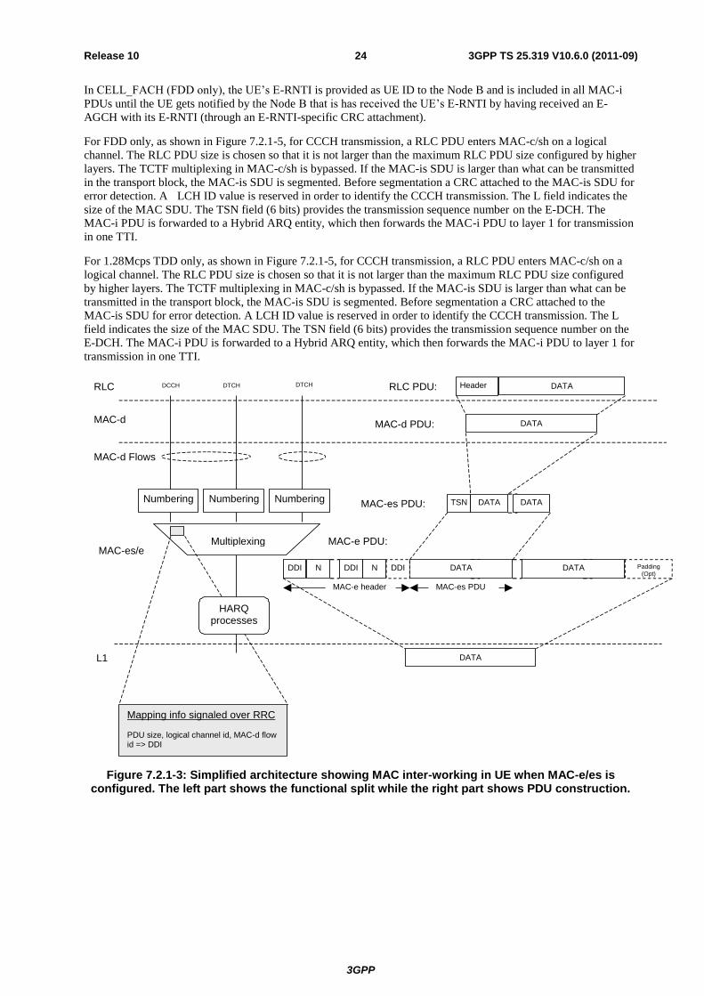
As shown in Figure 7.2.1-3, a RLC PDU enters MAC-d on a logical channel. The MAC-d C/T multiplexing is
bypassed. In the MAC-e header, the DDI (Data Description Indicator) field (6 bits) identifies logical channel, MAC-
d flow and MAC-d PDU size. A mapping table is signalled over RRC, to allow the UE to set DDI values. The N
field (fixed size of 6 bits) indicates the number of consecutive MAC-d PDUs corresponding to the same DDI value.
A special value of the DDI field indicates that no more data is contained in the remaining part of the MAC-e
PDU.The TSN field (6 bits) provides the transmission sequence number on the E-DCH. The MAC-e PDU is
forwarded to a Hybrid ARQ entity, which then forwards the MAC-e PDU to layer 1 for transmission in one TTI.
As shown in Figure 7.2.1-4 for DCCH and DTCH transmission, a RLC PDU enters MAC-d on a logical channel.
The RLC PDU size is chosen so that it is not smaller than the minimum RLC PDU size configured by higher layers
(unless there are no further data in the buffer) and not larger than the maximum RLC PDU size configured by higher
layers. The MAC-d C/T multiplexing is bypassed. If the MAC-is SDU is larger that what can be transmitted in the
transport block, the MAC-is SDU is segmented. In the MAC-i header, the LCH-ID (Logical Channel Indicator) field
(4 bits) identifies the logical channel and MAC-d flow. The L field indicates the size of the MAC SDU. The TSN
field (6 bits) provides the transmission sequence number on the E-DCH. The MAC-i PDU is forwarded to a Hybrid
ARQ entity, which then forwards the MAC-i PDU to layer 1 for transmission in one TTI.
3GPP
3GPP TS 25.319 V10.6.0 (2011-09) 24 Release 10
In CELL_FACH (FDD only), the UE’s E-RNTI is provided as UE ID to the Node B and is included in all MAC-i
PDUs until the UE gets notified by the Node B that is has received the UE’s E-RNTI by having received an E-
AGCH with its E-RNTI (through an E-RNTI-specific CRC attachment).
For FDD only, as shown in Figure 7.2.1-5, for CCCH transmission, a RLC PDU enters MAC-c/sh on a logical
channel. The RLC PDU size is chosen so that it is not larger than the maximum RLC PDU size configured by higher
layers. The TCTF multiplexing in MAC-c/sh is bypassed. If the MAC-is SDU is larger than what can be transmitted
in the transport block, the MAC-is SDU is segmented. Before segmentation a CRC attached to the MAC-is SDU for
error detection. A LCH ID value is reserved in order to identify the CCCH transmission. The L field indicates the
size of the MAC SDU. The TSN field (6 bits) provides the transmission sequence number on the E-DCH. The
MAC-i PDU is forwarded to a Hybrid ARQ entity, which then forwards the MAC-i PDU to layer 1 for transmission
in one TTI.
For 1.28Mcps TDD only, as shown in Figure 7.2.1-5, for CCCH transmission, a RLC PDU enters MAC-c/sh on a
logical channel. The RLC PDU size is chosen so that it is not larger than the maximum RLC PDU size configured
by higher layers. The TCTF multiplexing in MAC-c/sh is bypassed. If the MAC-is SDU is larger than what can be
transmitted in the transport block, the MAC-is SDU is segmented. Before segmentation a CRC attached to the
MAC-is SDU for error detection. A LCH ID value is reserved in order to identify the CCCH transmission. The L
field indicates the size of the MAC SDU. The TSN field (6 bits) provides the transmission sequence number on the
E-DCH. The MAC-i PDU is forwarded to a Hybrid ARQ entity, which then forwards the MAC-i PDU to layer 1 for
transmission in one TTI.
MAC-d Flows
MAC-es PDU MAC-e header
DCCH DTCH DTCH
HARQ processes
Multiplexing
DATA
MAC-d DATA
DATA
DDI N Padding
(Opt)
RLC PDU:
MAC-e PDU:
L1
RLC
DDI N
Mapping info signaled over RRC PDU size, logical channel id, MAC-d flow id => DDI
DATA DATA
MAC-d PDU:
DDI
Header
MAC-es/e
Numbering MAC-es PDU: TSN DATA DATA Numbering Numbering
Figure 7.2.1-3: Simplified architecture showing MAC inter-working in UE when MAC-e/es is configured. The left part shows the functional split while the right part shows PDU construction.

3GPP
3GPP TS 25.319 V10.6.0 (2011-09) 25 Release 10
MAC - d Flows
MAC - is PDU MAC - i header
DCCH
DTCH
DTCH
HARQ processes
Multiplexing
DATA
MAC - d DATA
DATA
Padding
(Opt)
RLC PDU:
MAC - i PDU:
L1
RLC
L DATA
DATA
MAC - d PDU:
Header
MAC - is/i
Numbering MAC - is PDU: TSN DATA
DATA
Numbering Numbering
LCH Add UE-id (FDD only)
SS
Figure 7.2.1-4: Simplified architecture showing MAC inter-working in UE when MAC-i/is is configured for DTCH and DCCH transmission. The left part shows the functional split while the
right part shows PDU construction.
MAC- is PDUi header
CCCH
HARQ
processes
Multiplexing
MAC-c DATA
DATA
RLC PDU:
MAC-i PDU:
L1
RLC
L DATA
MAC-c PDU:
MAC-is/i
MAC-is PDU: DATANumbering
LCH
DATA
MAC-
DATA
SS DATA
CRCCRC Attachment
paddingSI(opt) (opt)
TSN SS TSN
Figure 7.2.1-5: Simplified architecture showing MAC inter-working in UE when MAC-i/is is configured for CCCH transmission. The left part shows the functional split while the right part
shows PDU construction.
7.2.2 Details of MAC-d

3GPP
3GPP TS 25.319 V10.6.0 (2011-09) 26 Release 10
For support of E-DCH a new connection to MAC-es or MAC-is is added.
DCCH
DTCH
DTCH
MAC - d
from MAC - hs
Ciphering
MAC Control
UL: TFC selection
C/T MUX
C/T
MUX
Deciphering
Transport Channel Type Switching
to/from MAC - c/sh
to MAC - e/es
or MAC-i/is
Figure 7.2.2-1: UE side MAC architecture/ MAC-d details
7.2.3 Details of MAC-c/sh
For TDD, the support of E-DCH implies no change to the UE MAC-c/sh entity.
For FDD and 1.28Mcps TDD, for support of Enhanced Uplink in CELL_FACH and Idle mode a new connection to
MAC-is is added.
MAC-c/sh/m
MAC – Control
to MAC –d
FACH
FACH
CTCH CCCH BCCH SHCCH (TDD only) PCCH
PCH
UL: TF selection
USCH TDD only
RACH
Scheduling/Priority Handling (1)
USCH TDD only
TFC selection
ASC selection
MCCH MTCH MTCH
read MBMS Id
MSCH
TCTF MUX
DSCH TDD only
DSCH TDD only
From MAC-ehs
(FDD only)
Note: Dashed lines are FDD only
add/read UE Id
to MAC-is/i
Figure 7.2.3-1: UE side MAC architecture / MAC-c/sh/m details

3GPP
3GPP TS 25.319 V10.6.0 (2011-09) 27 Release 10
7.2.4 Details of MAC-hs
The support of E-DCH implies no change to the UE MAC-hs entity.
7.2.5 Details of MAC-es/MAC-e
The MAC-es/e handles the E-DCH specific functions. The split between MAC-e and MAC-es in the UE is not
detailed. In the model below the MAC-e/es comprises the following entities:
- HARQ:
The HARQ entity is responsible for handling the MAC functions relating to the HARQ protocol. It is
responsible for storing MAC-e payloads and re-transmitting them. The detailed configuration of the hybrid
ARQ protocol is provided by RRC over the MAC-Control SAP. The HARQ entity provides the E-TFC, the
retransmission sequence number (RSN), and the power offset to be used by L1. Redundancy version (RV) of
the HARQ transmission is derived by L1 from RSN, CFN and in case of 2 ms TTI from the sub-frame
number. RRC signalling can also configure the HARQ entity to use RV=0 for every transmission.
- Multiplexing and TSN setting:
The multiplexing and TSN setting entity is responsible for concatenating multiple MAC-d PDUs into MAC-
es PDUs, and to multiplex one or multiple MAC-es PDUs into a single MAC-e PDU, to be transmitted in the
next TTI, as instructed by the E-TFC selection function. It is also responsible for managing and setting the
TSN per logical channel for each MAC-es PDU.
- E-TFC selection:
This entity is responsible for E-TFC selection according to the scheduling information (Relative Grants and
Absolute Grants) received from UTRAN via L1, and for arbitration among the different flows mapped on the
E-DCH. The detailed configuration of the E-TFC entity is provided by RRC over the MAC-Control SAP.
The E-TFC selection function controls the multiplexing function.
- Scheduling Access Control (TDD only):
The Scheduling Access Control entity is responsible for routing associated uplink signalling via E-UCCH
and MAC-e PDU (in the case that E-DCH resources are assigned) or via E-RUCCH (in the case that no E-
DCH resources are assigned). It is also responsible for obtaining and formatting the appropriate information
to be carried on E-UCCH/E-RUCCH.
NOTE: HARQ process ID and RSN are carried on E-UCCH.

3GPP
3GPP TS 25.319 V10.6.0 (2011-09) 28 Release 10
MAC-es/e
MAC – Control
Associated Uplink Signalling E-TFC
(E-DPCCH)
To MAC-d
HARQ
Multiplexing and TSN setting E-TFC Selection
Associated Scheduling Downlink Signalling
(E-AGCH / E-RGCH(s))
Associated ACK/NACK signaling (E-HICH)
Figure 7.2.5-1: UE side MAC architecture / MAC-es/e details (FDD)
Scheduling Access Control
MAC-es/e
MAC – Control
To MAC-d
HARQ
Multiplexing and TSN setting E-TFC Selection
Associated Scheduling Downlink Signalling
(E-AGCH )
Associated ACK/NACK signaling (E-HICH)
Associated Uplink Signalling E-RUCCH
Associated Uplink Signalling E-UCCH
Figure 7.2.5-2: UE side MAC architecture / MAC-es/e details (TDD)
7.2.6 Details of MAC-is/MAC-i
The MAC-is/i handles the E-DCH specific functions. The split between MAC-i and MAC-is in the UE is not
detailed. In the model below the MAC-i/is comprises the following entities:
3GPP
3GPP TS 25.319 V10.6.0 (2011-09) 29 Release 10
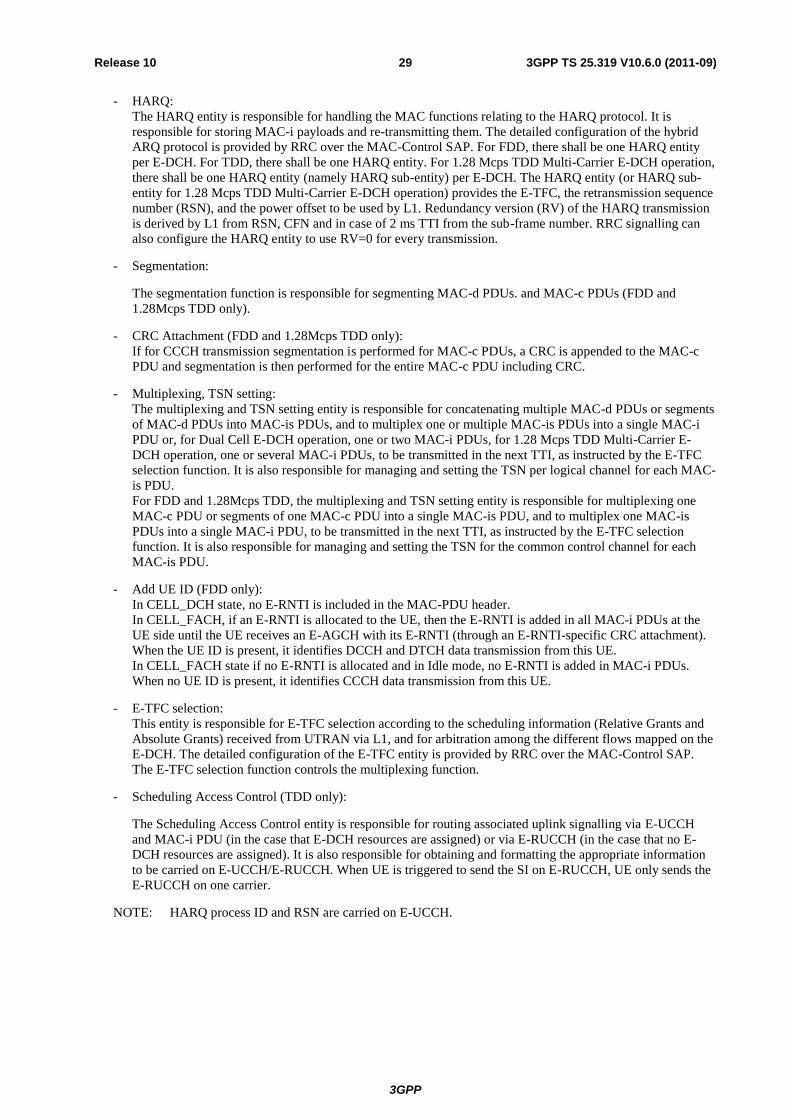
- HARQ:
The HARQ entity is responsible for handling the MAC functions relating to the HARQ protocol. It is
responsible for storing MAC-i payloads and re-transmitting them. The detailed configuration of the hybrid
ARQ protocol is provided by RRC over the MAC-Control SAP. For FDD, there shall be one HARQ entity
per E-DCH. For TDD, there shall be one HARQ entity. For 1.28 Mcps TDD Multi-Carrier E-DCH operation,
there shall be one HARQ entity (namely HARQ sub-entity) per E-DCH. The HARQ entity (or HARQ sub-
entity for 1.28 Mcps TDD Multi-Carrier E-DCH operation) provides the E-TFC, the retransmission sequence
number (RSN), and the power offset to be used by L1. Redundancy version (RV) of the HARQ transmission
is derived by L1 from RSN, CFN and in case of 2 ms TTI from the sub-frame number. RRC signalling can
also configure the HARQ entity to use RV=0 for every transmission.
- Segmentation:
The segmentation function is responsible for segmenting MAC-d PDUs. and MAC-c PDUs (FDD and
1.28Mcps TDD only).
- CRC Attachment (FDD and 1.28Mcps TDD only):
If for CCCH transmission segmentation is performed for MAC-c PDUs, a CRC is appended to the MAC-c
PDU and segmentation is then performed for the entire MAC-c PDU including CRC.
- Multiplexing, TSN setting:
The multiplexing and TSN setting entity is responsible for concatenating multiple MAC-d PDUs or segments
of MAC-d PDUs into MAC-is PDUs, and to multiplex one or multiple MAC-is PDUs into a single MAC-i
PDU or, for Dual Cell E-DCH operation, one or two MAC-i PDUs, for 1.28 Mcps TDD Multi-Carrier E-
DCH operation, one or several MAC-i PDUs, to be transmitted in the next TTI, as instructed by the E-TFC
selection function. It is also responsible for managing and setting the TSN per logical channel for each MAC-
is PDU.
For FDD and 1.28Mcps TDD, the multiplexing and TSN setting entity is responsible for multiplexing one
MAC-c PDU or segments of one MAC-c PDU into a single MAC-is PDU, and to multiplex one MAC-is
PDUs into a single MAC-i PDU, to be transmitted in the next TTI, as instructed by the E-TFC selection
function. It is also responsible for managing and setting the TSN for the common control channel for each
MAC-is PDU.
- Add UE ID (FDD only):
In CELL_DCH state, no E-RNTI is included in the MAC-PDU header.
In CELL_FACH, if an E-RNTI is allocated to the UE, then the E-RNTI is added in all MAC-i PDUs at the
UE side until the UE receives an E-AGCH with its E-RNTI (through an E-RNTI-specific CRC attachment).
When the UE ID is present, it identifies DCCH and DTCH data transmission from this UE.
In CELL_FACH state if no E-RNTI is allocated and in Idle mode, no E-RNTI is added in MAC-i PDUs.
When no UE ID is present, it identifies CCCH data transmission from this UE.
- E-TFC selection:
This entity is responsible for E-TFC selection according to the scheduling information (Relative Grants and
Absolute Grants) received from UTRAN via L1, and for arbitration among the different flows mapped on the
E-DCH. The detailed configuration of the E-TFC entity is provided by RRC over the MAC-Control SAP.
The E-TFC selection function controls the multiplexing function.
- Scheduling Access Control (TDD only):
The Scheduling Access Control entity is responsible for routing associated uplink signalling via E-UCCH
and MAC-i PDU (in the case that E-DCH resources are assigned) or via E-RUCCH (in the case that no E-
DCH resources are assigned). It is also responsible for obtaining and formatting the appropriate information
to be carried on E-UCCH/E-RUCCH. When UE is triggered to send the SI on E-RUCCH, UE only sends the
E-RUCCH on one carrier.
NOTE: HARQ process ID and RSN are carried on E-UCCH.

3GPP
3GPP TS 25.319 V10.6.0 (2011-09) 30 Release 10
MAC-is/i
MAC – Control
to MAC-d
E-TFC Selection
Associated Scheduling
Downlink Signaling (E-AGCH / E-RGCH)
Segmentation SegmentationSegmentation
to MAC-c
Multiplexing and TSN setting
CRC Attachment
HARQ
Add UE id
ASC Selection
-
HARQ
E-DCH E-DCH
Associated
ACK/NACK
Signalling
(E-HICH)
Associated
ACK/NACK
Signalling
(E-HICH)
Associated
Uplink
Signalling
E-TFC
(E-DPCCH)
Associated
Uplink
Signalling
E-TFC
(E-DPCCH)
Figure 7.2.6-1: UE side MAC architecture / MAC-is/i details (FDD)
Scheduling Access Control
MAC-is/i
M AC – Control
To MAC - d
HARQ
Multiplexing and TSN setting E-TFC Selection
Associated Scheduling Downlink Signalling
( E - AGCH )
Associated ACK/NACK signaling ( E - HICH )
Associated Uplink Signalling E - RUCCH
Associated Uplink Signalling E - UCCH
Segmentation Segmentation
Figure 7.2.6-2: UE side MAC architecture / MAC-is/i details (3.84Mcps TDD and 7.68Mcps TDD)

3GPP
3GPP TS 25.319 V10.6.0 (2011-09) 31 Release 10
CRC Attachment
Multiplexing and TSN setting
Segmentation
Segmentation Segmentation
HARQ
E-TFC SelectionScheduling
Access Control
Associated
ACK/NACK Signalling
(E-HICH)
Associated
Uplink Signalling
(E-UCCH)
Associated
Uplink Signalling
(E-RUCCH)
Associated
Scheduling Downlink
Signalling
(E-AGCH)
MAC-Control
to MAC-c to MAC-d
MAC-is/i
Figure 7.2.6-3: UE side MAC architecture / MAC-is/i details (1.28Mcps TDD)
Multiplexing and TSN setting
Segmentation Segmentation
E-TFC SelectionScheduling
Access Control
Associated
ACK/NACK Signalling
(E-HICH)
Associated
Uplink Signalling
(E-UCCH)
Associated
Uplink Signalling
(E-RUCCH)
Associated
Scheduling Downlink
Signalling
(E-AGCHs)
MAC-Control
to MAC-d
MAC-is/i
…
Associated
ACK/NACK Signalling
(E-HICH)
Associated
Uplink Signalling
(E-UCCH)
…
Carrier 1 Carrier n
HARQ sub-entity
(carrier n)HARQ sub-entity
(carrier 1)
Figure 7.2.6-3a: UE side MAC architecture / MAC-is/i details (1.28 Mcps TDD Multi-Carrier E-DCH operation)
3GPP
3GPP TS 25.319 V10.6.0 (2011-09) 32 Release 10
7.3 MAC architecture – UTRAN side
7.3.1 Overall architecture
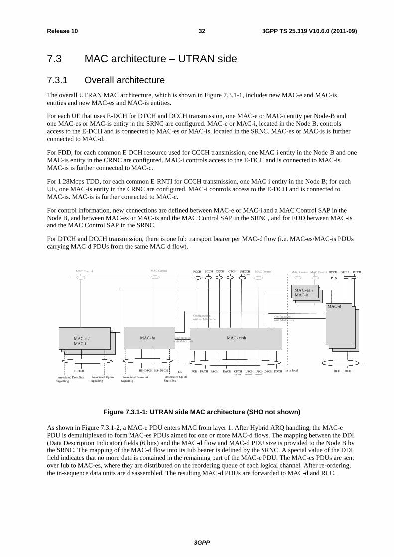
The overall UTRAN MAC architecture, which is shown in Figure 7.3.1-1, includes new MAC-e and MAC-is
entities and new MAC-es and MAC-is entities.
For each UE that uses E-DCH for DTCH and DCCH transmission, one MAC-e or MAC-i entity per Node-B and
one MAC-es or MAC-is entity in the SRNC are configured. MAC-e or MAC-i, located in the Node B, controls
access to the E-DCH and is connected to MAC-es or MAC-is, located in the SRNC. MAC-es or MAC-is is further
connected to MAC-d.
For FDD, for each common E-DCH resource used for CCCH transmission, one MAC-i entity in the Node-B and one
MAC-is entity in the CRNC are configured. MAC-i controls access to the E-DCH and is connected to MAC-is.
MAC-is is further connected to MAC-c.
For 1.28Mcps TDD, for each common E-RNTI for CCCH transmission, one MAC-i entity in the Node B; for each
UE, one MAC-is entity in the CRNC are configured. MAC-i controls access to the E-DCH and is connected to
MAC-is. MAC-is is further connected to MAC-c.
For control information, new connections are defined between MAC-e or MAC-i and a MAC Control SAP in the
Node B, and between MAC-es or MAC-is and the MAC Control SAP in the SRNC, and for FDD between MAC-is
and the MAC Control SAP in the SRNC.
For DTCH and DCCH transmission, there is one Iub transport bearer per MAC-d flow (i.e. MAC-es/MAC-is PDUs
carrying MAC-d PDUs from the same MAC-d flow).
FACH RACH
DCCH DTCHDTCH
DSCH
MAC Control
Iur or local
MAC Control
DCH DCH
MAC-d
USCHTDD only
MAC- c/sh
CPCHFDD only
CCCH CTCHBCCH SHCCHTDD only
PCCH
FACHPCH USCHTDD only
DSCH
MAC Control
HS- DSCH HS- DSCH
Associated Uplink
SignallingAssociated Downlink
Signalling
MAC-hs
Configuration
without MAC- c/shConfiguration
with MAC
Configuration
with MAC- c/sh
E- DCH
Associated Uplink
SignallingAssociated Downlink
Signalling
MAC Control
MAC-es /
MAC-e /
MAC Control
Iub
c/sh
MAC-i
MAC-is
Figure 7.3.1-1: UTRAN side MAC architecture (SHO not shown)
As shown in Figure 7.3.1-2, a MAC-e PDU enters MAC from layer 1. After Hybrid ARQ handling, the MAC-e
PDU is demultiplexed to form MAC-es PDUs aimed for one or more MAC-d flows. The mapping between the DDI
(Data Description Indicator) fields (6 bits) and the MAC-d flow and MAC-d PDU size is provided to the Node B by
the SRNC. The mapping of the MAC-d flow into its Iub bearer is defined by the SRNC. A special value of the DDI
field indicates that no more data is contained in the remaining part of the MAC-e PDU. The MAC-es PDUs are sent
over Iub to MAC-es, where they are distributed on the reordering queue of each logical channel. After re-ordering,
the in-sequence data units are disassembled. The resulting MAC-d PDUs are forwarded to MAC-d and RLC.

3GPP
3GPP TS 25.319 V10.6.0 (2011-09) 33 Release 10
Mac-es PDU:
Reordering queue distribution
Reordering queue distribution
DCCH DTCH DTCH
MAC-d Flows
HARQ
Demultiplexing
DATA Header
MAC-d
MAC-e
DATA
DATA
DATA DATA
MAC-e PDU:
RLC PDU:
L1
RLC
Reordering
MAC-es
Reordering Reordering
Disassembly Disassembly Disassembly
MAC-d PDU:
Mapping info signaled to Node B DDI => MAC-d PDU size, MAC-d flow ID
TSN
MAC-e header
DDI N Padding (Opt)
DDI N DATA DATA DDI
Transport block:
DDI N Iub FP:
Figure 7.3.1-2: Simplified architecture showing MAC inter-working in UTRAN (MAC-e/es configured). The left part shows the functional split while the right part shows PDU
decomposition.
In CELL_DCH state, as shown in Figure 7.3.1-3, a MAC-i PDU enters MAC from layer 1. After Hybrid ARQ
handling, the MAC-i PDU is demultiplexed to form MAC-is PDUs aimed for one or more MAC-d flows. The
mapping between the LCH-ID field and the MAC-d flow is provided to the Node B by the SRNC. The mapping of
the MAC-d flow into its Iub bearer is defined by the SRNC. The MAC-is PDUs are sent over Iub to MAC-is, where
they are distributed on the reordering queue of each logical channel. After re-ordering, the in-sequence data units are
reassembled and disassembled to create MAC-d PDUs. The resulting MAC-d PDUs are forwarded to MAC-d and
RLC.
For FDD only, in CELL_FACH state for DTCH and DCCH transmission, as shown in Figure 7.3.1-3, a MAC-i
PDU enters MAC from layer 1. After Hybrid ARQ handling, and if the UE ID is not known to the Node B, the UE’s
E-RNTI is read in the MAC-i PDU. The MAC-i PDU is then demultiplexed to form MAC-is PDUs aimed for one or
more MAC-d flow in CELL_FACH. The mapping between the LCH-ID field and the MAC-d flow is provided to
the Node B by the CRNC. The mapping of the MAC-d flow into its Iub bearer is defined by the CRNC. The MAC-
is PDUs are sent over Iub to MAC-is, where they are distributed on the reordering queue of each logical channel.
After re-ordering, the in-sequence data units are reassembled and disassembled to create MAC-d PDUs. The
resulting MAC-d PDUs are forwarded to MAC-d and RLC.
For FDD, for CCCH transmission, as shown in Figure 7.3.1-4, a MAC-i PDU enters MAC from layer 1. After
Hybrid ARQ handling, the MAC-i PDU is demultiplexed to from one MAC-is PDU aimed for MAC-is, where it is
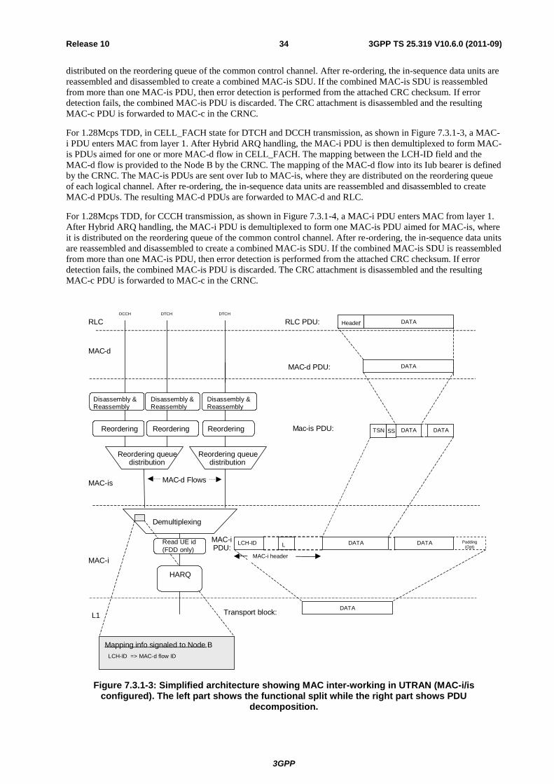
3GPP
3GPP TS 25.319 V10.6.0 (2011-09) 34 Release 10
distributed on the reordering queue of the common control channel. After re-ordering, the in-sequence data units are
reassembled and disassembled to create a combined MAC-is SDU. If the combined MAC-is SDU is reassembled
from more than one MAC-is PDU, then error detection is performed from the attached CRC checksum. If error
detection fails, the combined MAC-is PDU is discarded. The CRC attachment is disassembled and the resulting
MAC-c PDU is forwarded to MAC-c in the CRNC.
For 1.28Mcps TDD, in CELL_FACH state for DTCH and DCCH transmission, as shown in Figure 7.3.1-3, a MAC-
i PDU enters MAC from layer 1. After Hybrid ARQ handling, the MAC-i PDU is then demultiplexed to form MAC-
is PDUs aimed for one or more MAC-d flow in CELL_FACH. The mapping between the LCH-ID field and the
MAC-d flow is provided to the Node B by the CRNC. The mapping of the MAC-d flow into its Iub bearer is defined
by the CRNC. The MAC-is PDUs are sent over Iub to MAC-is, where they are distributed on the reordering queue
of each logical channel. After re-ordering, the in-sequence data units are reassembled and disassembled to create
MAC-d PDUs. The resulting MAC-d PDUs are forwarded to MAC-d and RLC.
For 1.28Mcps TDD, for CCCH transmission, as shown in Figure 7.3.1-4, a MAC-i PDU enters MAC from layer 1.
After Hybrid ARQ handling, the MAC-i PDU is demultiplexed to form one MAC-is PDU aimed for MAC-is, where
it is distributed on the reordering queue of the common control channel. After re-ordering, the in-sequence data units
are reassembled and disassembled to create a combined MAC-is SDU. If the combined MAC-is SDU is reassembled
from more than one MAC-is PDU, then error detection is performed from the attached CRC checksum. If error
detection fails, the combined MAC-is PDU is discarded. The CRC attachment is disassembled and the resulting
MAC-c PDU is forwarded to MAC-c in the CRNC.
Mac-is PDU:
Reordering queue distribution
Reordering queue distribution
DCCH DTCH DTCH
MAC-d Flows
HARQ
Demultiplexing
DATAHeader
MAC-d
MAC-i
DATA
DATA
DATA DATA
MAC-iPDU:
RLC PDU:
L1
RLC
Reordering
MAC-is
Reordering Reordering
Disassembly & Reassembly
MAC-d PDU:
Mapping info signaled to Node B
MAC-i header
LCH-ID Padding
(Opt)L DATADATA
Transport block:
LCH-ID => MAC-d flow ID
Disassembly & Reassembly
Disassembly & Reassembly
Read UE id
(FDD only)
TSN SS
Figure 7.3.1-3: Simplified architecture showing MAC inter-working in UTRAN (MAC-i/is configured). The left part shows the functional split while the right part shows PDU
decomposition.
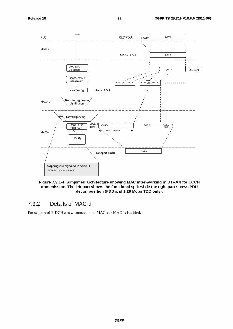
3GPP
3GPP TS 25.319 V10.6.0 (2011-09) 35 Release 10
Mac-is PDU:
Reordering queue distribution
CCCH
HARQ
Demultiplexing
DATAHeader
MAC-c
MAC-i
DATA
DATA
DATA
MAC-iPDU:
RLC PDU:
L1
RLC
MAC-is
Reordering
MAC-c PDU:
Mapping info signaled to Node B
MAC-i header
LCH-ID Padding
(Opt)L DATA
Transport block:
LCH-ID => MAC-d flow ID
Disassembly & Reassembly
Read UE id
(FDD only)
CRC Error
Detection
DATATSN
CRC (opt)DATA
SS TSN SS
Figure 7.3.1-4: Simplified architecture showing MAC inter-working in UTRAN for CCCH transmission. The left part shows the functional split while the right part shows PDU
decomposition (FDD and 1.28 Mcps TDD only).
7.3.2 Details of MAC-d
For support of E-DCH a new connection to MAC-es / MAC-is is added.

3GPP
3GPP TS 25.319 V10.6.0 (2011-09) 36 Release 10
DCCH
DTCH
DTCH
DCH
DCH
MAC - d to MAC - c/sh
MA C - Control
C/T
MUX
DL scheduling/ priority handling
Ciphering
Transport Channel Type Switching
Deciphering
to MAC - hs
to MAC-es /
Flow Control
C/T MUX / Priority
setting (DL)
MAC-is
Figure 7.3.2-1: UTRAN side MAC architecture / MAC-d details
7.3.3 Details of MAC-c/sh
For 3.84Mcps TDD and 7.68Mcps TDD, the support of E-DCH implies no change to the UTRAN MAC-c/sh entity.
For FDD, for support of Enhanced Uplink in CELL_FACH and Idle mode a new connection to MAC-is is added.
For 1.28Mcps TDD, for support of Enhanced Uplink in CELL_FACH and Idle mode a new connection to MAC-is is
added.
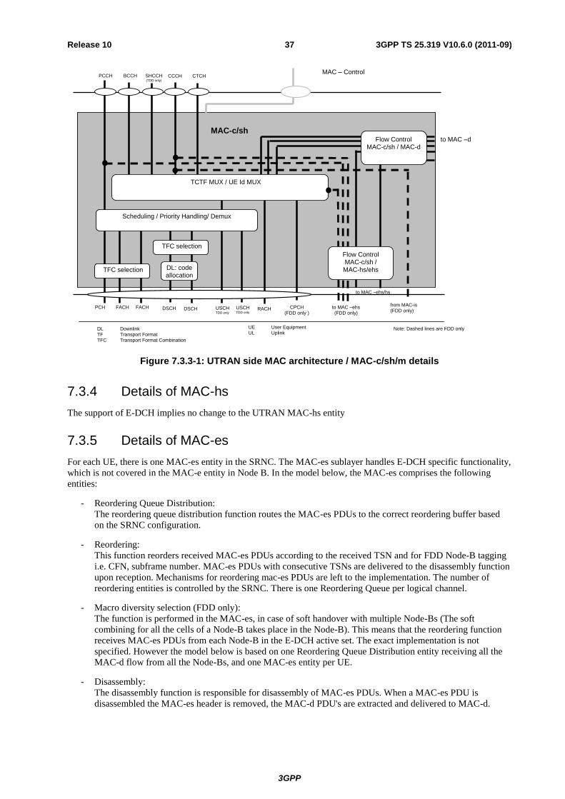
3GPP
3GPP TS 25.319 V10.6.0 (2011-09) 37 Release 10
UE User Equipment UL Uplink
CTCH
FACH
MAC-c/sh to MAC –d
RACH
MAC – Control
CPCH (FDD only )
CCCH
FACH
BCCH SHCCH (TDD only)
PCCH
PCH
TFC selection
DSCH USCH TDD only
USCH TDD only
DSCH
DL: code allocation
TFC selection
to MAC –ehs/hs
Flow Control MAC-c/sh / MAC-d
to MAC –ehs (FDD only)
Flow Control MAC-c/sh /
MAC-hs/ehs
Note: Dashed lines are FDD only
Scheduling / Priority Handling/ Demux
TCTF MUX / UE Id MUX
DL Downlink TF Transport Format TFC Transport Format Combination
from MAC-is (FDD only)
Figure 7.3.3-1: UTRAN side MAC architecture / MAC-c/sh/m details
7.3.4 Details of MAC-hs
The support of E-DCH implies no change to the UTRAN MAC-hs entity
7.3.5 Details of MAC-es
For each UE, there is one MAC-es entity in the SRNC. The MAC-es sublayer handles E-DCH specific functionality,
which is not covered in the MAC-e entity in Node B. In the model below, the MAC-es comprises the following
entities:
- Reordering Queue Distribution:
The reordering queue distribution function routes the MAC-es PDUs to the correct reordering buffer based
on the SRNC configuration.
- Reordering:
This function reorders received MAC-es PDUs according to the received TSN and for FDD Node-B tagging
i.e. CFN, subframe number. MAC-es PDUs with consecutive TSNs are delivered to the disassembly function
upon reception. Mechanisms for reordering mac-es PDUs are left to the implementation. The number of
reordering entities is controlled by the SRNC. There is one Reordering Queue per logical channel.
- Macro diversity selection (FDD only):
The function is performed in the MAC-es, in case of soft handover with multiple Node-Bs (The soft
combining for all the cells of a Node-B takes place in the Node-B). This means that the reordering function
receives MAC-es PDUs from each Node-B in the E-DCH active set. The exact implementation is not
specified. However the model below is based on one Reordering Queue Distribution entity receiving all the
MAC-d flow from all the Node-Bs, and one MAC-es entity per UE.
- Disassembly:
The disassembly function is responsible for disassembly of MAC-es PDUs. When a MAC-es PDU is
disassembled the MAC-es header is removed, the MAC-d PDU's are extracted and delivered to MAC-d.

3GPP
3GPP TS 25.319 V10.6.0 (2011-09) 38 Release 10
MAC-es
MAC – Control
From MAC-e in NodeB #1
To MAC-d
Disassembly
Reordering Queue Distribution
Reordering Queue Distribution
Disassembly
Reordering/ Combining
Disassembly
Reordering/ Combining
Reordering/ Combining
From MAC-e in NodeB #k
MAC-d flow #1 MAC-d flow #n
Figure 7.3.5-1: UTRAN side MAC architecture / MAC-es details (SHO case, FDD only)

3GPP
3GPP TS 25.319 V10.6.0 (2011-09) 39 Release 10
MAC-es
MAC – Control
From MAC-e in NodeB
To MAC-d
Disassembly
Reordering Queue Distribution
Reordering Queue Distribution
Disassembly
Reordering
Disassembly
Reordering Reordering
MAC-d flow #1 MAC-d flow #n
Figure 7.3.5-2: UTRAN side MAC architecture / MAC-es details (TDD only)
7.3.6 Details of MAC-e
There is one MAC-e entity in the NodeB for each UE and one E-DCH scheduler function in the Node-B. The MAC-
e and E-DCH scheduler handle Enhanced Uplink specific functions in the NodeB. In the model below, the MAC-e
and E-DCH scheduler comprises the following entities:
- E-DCH Scheduling:
This function manages E-DCH cell resources between UEs. Based on scheduling requests, Scheduling
Grants are determined and transmitted. The general principles of the E-DCH scheduling are described in
subclause 9.1 below. However implementation is not specified (i.e. depends on RRM strategy).
- E-DCH Control:
The E-DCH control entity is responsible for reception of scheduling requests and transmission of Scheduling
Grants. The general principles of the E-DCH scheduling are described in subclause 9.1 below.
- De-multiplexing:
This function provides de-multiplexing of MAC-e PDUs. MAC-es PDUs are forwarded to the associated
MAC-d flow.
- HARQ:
One HARQ entity is capable of supporting multiple instances (HARQ processes) of stop and wait HARQ
protocols. Each process is responsible for generating ACKs or NACKs indicating delivery status of E-DCH
transmissions. The HARQ entity handles all tasks that are required for the HARQ protocol.
The associated signalling shown in the figure illustrates the exchange of information between layer 1 and layer 2
provided by primitives.
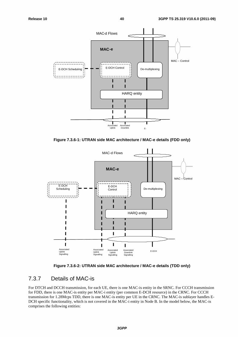
3GPP
3GPP TS 25.319 V10.6.0 (2011-09) 40 Release 10
MAC - e
MAC – Control
E - Associated Downlink
Associated Uplink
MAC - d Flows
De - multiplexing
HARQ entity
E-DCH Control E-DCH Scheduling
Figure 7.3.6-1: UTRAN side MAC architecture / MAC-e details (FDD only)
MAC – Control
E-DCH Scheduling
MAC-e
E-DCH Associated Downlink Signalling
Associated Uplink
Signalling
MAC-d Flows
E-DCH Control
Associated Uplink
Signalling
Associated Uplink
Signalling
De-multiplexing
HARQ entity
Figure 7.3.6-2: UTRAN side MAC architecture / MAC-e details (TDD only)
7.3.7 Details of MAC-is
For DTCH and DCCH transmission, for each UE, there is one MAC-is entity in the SRNC. For CCCH transmission
for FDD, there is one MAC-is entity per MAC-i entity (per common E-DCH resource) in the CRNC. For CCCH
transmission for 1.28Mcps TDD, there is one MAC-is entity per UE in the CRNC. The MAC-is sublayer handles E-
DCH specific functionality, which is not covered in the MAC-i entity in Node B. In the model below, the MAC-is
comprises the following entities:
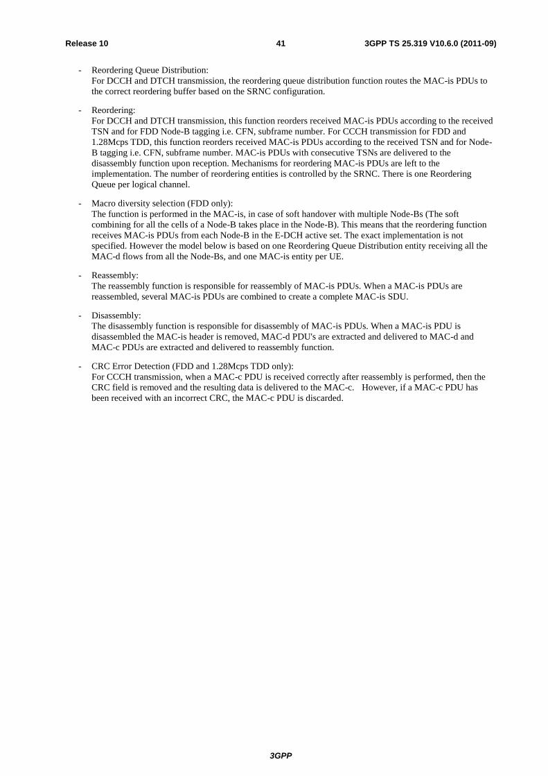
3GPP
3GPP TS 25.319 V10.6.0 (2011-09) 41 Release 10
- Reordering Queue Distribution:
For DCCH and DTCH transmission, the reordering queue distribution function routes the MAC-is PDUs to
the correct reordering buffer based on the SRNC configuration.
- Reordering:
For DCCH and DTCH transmission, this function reorders received MAC-is PDUs according to the received
TSN and for FDD Node-B tagging i.e. CFN, subframe number. For CCCH transmission for FDD and
1.28Mcps TDD, this function reorders received MAC-is PDUs according to the received TSN and for Node-
B tagging i.e. CFN, subframe number. MAC-is PDUs with consecutive TSNs are delivered to the
disassembly function upon reception. Mechanisms for reordering MAC-is PDUs are left to the
implementation. The number of reordering entities is controlled by the SRNC. There is one Reordering
Queue per logical channel.
- Macro diversity selection (FDD only):
The function is performed in the MAC-is, in case of soft handover with multiple Node-Bs (The soft
combining for all the cells of a Node-B takes place in the Node-B). This means that the reordering function
receives MAC-is PDUs from each Node-B in the E-DCH active set. The exact implementation is not
specified. However the model below is based on one Reordering Queue Distribution entity receiving all the
MAC-d flows from all the Node-Bs, and one MAC-is entity per UE.
- Reassembly:
The reassembly function is responsible for reassembly of MAC-is PDUs. When a MAC-is PDUs are
reassembled, several MAC-is PDUs are combined to create a complete MAC-is SDU.
- Disassembly:
The disassembly function is responsible for disassembly of MAC-is PDUs. When a MAC-is PDU is
disassembled the MAC-is header is removed, MAC-d PDU's are extracted and delivered to MAC-d and
MAC-c PDUs are extracted and delivered to reassembly function.
- CRC Error Detection (FDD and 1.28Mcps TDD only):
For CCCH transmission, when a MAC-c PDU is received correctly after reassembly is performed, then the
CRC field is removed and the resulting data is delivered to the MAC-c. However, if a MAC-c PDU has
been received with an incorrect CRC, the MAC-c PDU is discarded.

3GPP
3GPP TS 25.319 V10.6.0 (2011-09) 42 Release 10
MAC-is
MAC – Control
From
MAC - i in
NodeB #1
To MAC - d
Disassembly
Reordering Queue Distribution
Reordering Queue Distribution
Disassembly
Reordering/
Combining
Disassembly
Reordering/
Combining
Reorderi ng/
Combining
From
MAC - i in
NodeB #k
MAC - d flow #1 MAC - d flow #n
Reassembly Reassembly Reassembly
Figure 7.3.7-1: UTRAN side MAC architecture / MAC-is details (for DTCH and DCCH transmission, SHO case, FDD only)

3GPP
3GPP TS 25.319 V10.6.0 (2011-09) 43 Release 10
MAC-is
MAC – Control
From MAC-i &
NodeB #1
To MAC-d
Disassembly
Reordering Queue Distribution
Disassembly
Reordering/Combining
Disassembly
Reordering/Combining
Reordering/Combining
From MAC-i in
NodeB #k
ReassemblyReassembly Reassembly
carrier 1 in
From MAC-i &
NodeB #1
carrier 2 in carrier 1 in
From MAC-i in
NodeB #k
carrier 2 in
Reordering Queue Distribution
MAC-d flow #1 MAC-d flow #n
Figure 7.3.7-1a: UTRAN side MAC architecture / MAC-is details for Dual Cell E-DCH operation (for DTCH and DCCH transmission, SHO case, FDD only)

3GPP
3GPP TS 25.319 V10.6.0 (2011-09) 44 Release 10
MAC-is
MAC – Control
From
MAC - i in
Nod eB
To MAC - d
Disassembly
Reordering Queue Distribution
Reordering Queue Distribution
Disassembly
Reordering
Disassembly
Reordering Reorderi ng
MAC - d flow #1 MAC - d flow #n
Reassembly
Reassembly
Reassembly
Figure 7.3.7-2: UTRAN side MAC architecture / MAC-is details (for DTCH and DCCH transmission, TDD only)

3GPP
3GPP TS 25.319 V10.6.0 (2011-09) 45 Release 10
MAC-is
MAC – Control
From MAC-i in
the NodeB
To MAC-c
Disassembly
Reordering Queue Distribution
Reordering/Combining
Reassembly
CRC Error
Detection
Figure 7.3.7-3: UTRAN side MAC architecture / MAC-is details (for CCCH transmission, FDD and 1.28Mcps TDD only)
7.3.8 Details of MAC-i
In CELL_DCH state, there is one MAC-i entity in the NodeB for each UE.
For FDD, in CELL_FACH state and Idle mode, there is a collision resolution phase at the beginning of the data
transmission over the assigned common E-DCH resource where one or more UEs may access the MAC-i entity in
the Node B. After this phase the MAC-i entity in the Node B will be accessed at most by one UE.
For 1.28Mcps TDD, in CELL_FACH state and Idle mode, there is a common E-RNTI collision resolution phase at
the beginning of enhanced random access where one or more UEs may access the MAC-i entity in the Node B using
a same common E-RNTI. After this phase the MAC-i entity in the Node B will be accessed at most by one UE.
There is one E-DCH scheduler function in the Node-B. The MAC-i and E-DCH scheduler handle Enhanced Uplink
specific functions in the NodeB. In the model below, the MAC-i and E-DCH scheduler comprises the following
entities:
- E-DCH Scheduling:
This function manages E-DCH cell resources between UEs. Based on scheduling requests, Scheduling
Grants are determined and transmitted. The general principles of the E-DCH scheduling are described in
subclause 9.1 below. However implementation is not specified (i.e. depends on RRM strategy).
- E-DCH Control:
The E-DCH control entity is responsible for reception of scheduling requests and transmission of Scheduling
Grants. For FDD, for UEs in CELL_FACH state, the E-DCH control entity is additionally responsible for
collision resolution and common E-DCH resource release by transmitting Scheduling Grants. For 1.28Mcps
TDD, for UEs in CELL_FACH state, the E-DCH control entity is additionally responsible for common E-
RNTI collision resolution by transmitting Scheduling Grants.
The general principles of the E-DCH scheduling are described in subclause 9.1 below.
- De-multiplexing:
This function provides de-multiplexing of MAC-i PDUs. For DCCH and DTCH transmission, MAC-is PDUs
are forwarded to the associated MAC-d flow. For CCCH transmission, MAC-is PDUs are forwarded to the
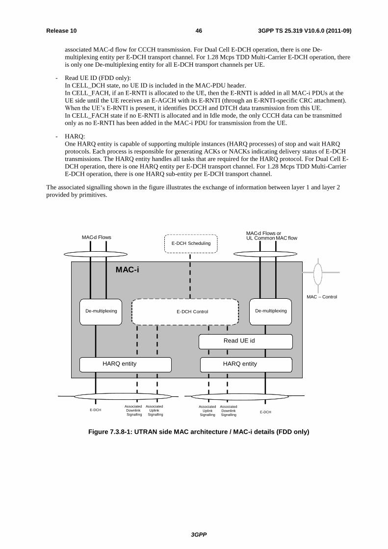
3GPP
3GPP TS 25.319 V10.6.0 (2011-09) 46 Release 10
associated MAC-d flow for CCCH transmission. For Dual Cell E-DCH operation, there is one De-
multiplexing entity per E-DCH transport channel. For 1.28 Mcps TDD Multi-Carrier E-DCH operation, there
is only one De-multiplexing entity for all E-DCH transport channels per UE.
- Read UE ID (FDD only):
In CELL_DCH state, no UE ID is included in the MAC-PDU header.
In CELL_FACH, if an E-RNTI is allocated to the UE, then the E-RNTI is added in all MAC-i PDUs at the
UE side until the UE receives an E-AGCH with its E-RNTI (through an E-RNTI-specific CRC attachment).
When the UE’s E-RNTI is present, it identifies DCCH and DTCH data transmission from this UE.
In CELL_FACH state if no E-RNTI is allocated and in Idle mode, the only CCCH data can be transmitted
only as no E-RNTI has been added in the MAC-i PDU for transmission from the UE.
- HARQ:
One HARQ entity is capable of supporting multiple instances (HARQ processes) of stop and wait HARQ
protocols. Each process is responsible for generating ACKs or NACKs indicating delivery status of E-DCH
transmissions. The HARQ entity handles all tasks that are required for the HARQ protocol. For Dual Cell E-
DCH operation, there is one HARQ entity per E-DCH transport channel. For 1.28 Mcps TDD Multi-Carrier
E-DCH operation, there is one HARQ sub-entity per E-DCH transport channel.
The associated signalling shown in the figure illustrates the exchange of information between layer 1 and layer 2
provided by primitives.
MAC-i
MAC – Control
E-DCH
Associated Downlink Signalling
Associated Uplink
Signalling
De-multiplexing
HARQ entity
E-DCH Scheduling
E-DCH Control
Read UE id
MAC-d Flows orUL Common MAC flow
De-multiplexing
Associated Downlink Signalling
Associated Uplink
Signalling
E-DCH
HARQ entity
MAC-d Flows
Figure 7.3.8-1: UTRAN side MAC architecture / MAC-i details (FDD only)
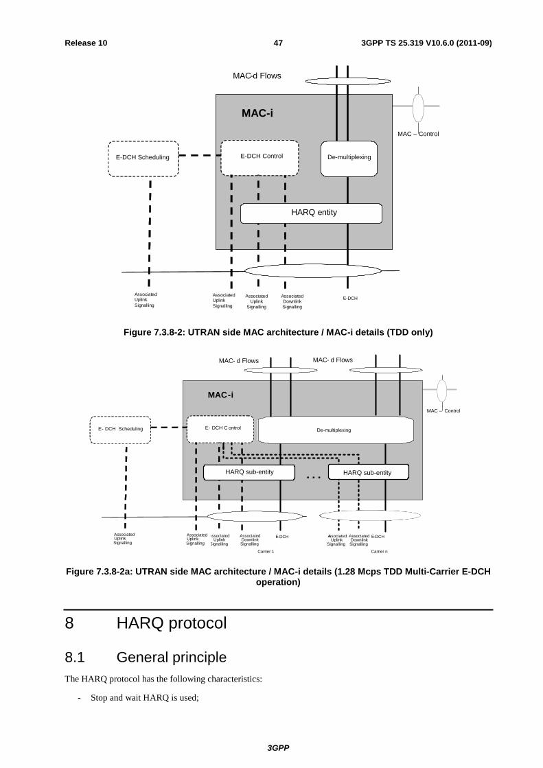
3GPP
3GPP TS 25.319 V10.6.0 (2011-09) 47 Release 10
MAC – Control
E-DCH Scheduling
MAC-i
E - DCH
Associated Downlink Signalling
A ssociated Uplink
Signalling
MAC - d Flows
Associated Uplink Signalling
Associated Uplink Signalling
De - multiplexing
HARQ entity
E-DCH Control
Figure 7.3.8-2: UTRAN side MAC architecture / MAC-i details (TDD only)
MAC – Control
E- DCH Scheduling
MAC-i
E - DCH
Associated
Downlink
Signalling
A ssociated
Uplink
Signalling
MAC - d Flows
Associated
Uplink
Signalling
Associated Uplink
Signalling
HARQ sub-entity
E- DCH C ontrol
MAC - d Flows
E-DCH
Associated
Downlink
Signalling
A ssociated
Uplink
Signalling
HARQ sub-entity…
Carrier 1 Carrier n
De-multiplexing
Figure 7.3.8-2a: UTRAN side MAC architecture / MAC-i details (1.28 Mcps TDD Multi-Carrier E-DCH operation)
8 HARQ protocol
8.1 General principle
The HARQ protocol has the following characteristics:
- Stop and wait HARQ is used;
3GPP
3GPP TS 25.319 V10.6.0 (2011-09) 48 Release 10
- The HARQ is based on synchronous downlink ACK/NACKs;
- There will be an upper limit to the number of retransmissions. The UE decides on a maximum number of
transmissions for a MAC-e / MAC-i PDU based on the maximum number of transmissions attribute (see
subclause 11.1.1), according to the following principles:
- The UE selects the highest 'maximum number of transmissions' among all the considered HARQ profiles
associated to the MAC-d flows in the MAC-e / MAC-i PDU.
- Pre-emption will not be supported by E-DCH (ongoing re-transmissions will not be pre-empted by higher
priority data for a particular process);
- Incremental redundancy shall be supported by the specifications with Chase combining as a subcase:
- The first transmission shall be self decodable;
- The UTRAN configures the UE to either use the same incremental redundancy version (RV) for
all transmissions, or to set the RV according to set of rules based on E-TFC, Retransmission Sequence
Number (RSN) and the transmission timing;
For FDD:
- The HARQ is based on synchronous retransmissions in the uplink:
- The number of processes per HARQ entity depends on the TTI: 8 processes for the 2ms TTI and 4
processes for the 10ms TTI. For both scheduled and non-scheduled transmission for a given UE, it is
possible to restrict the transmission to specific processes for the 2ms E-DCH TTI;
- In case of TTI reconfiguration, the MAC-e / MAC-i HARQ processes are flushed and no special
mechanism is defined to lower SDU losses.
- Intra Node B macro-diversity and Inter Node B macro-diversity should be supported for the E-DCH with
HARQ;
- There shall be no need, from the H-ARQ operation point of view, to reconfigure the Node B from upper
layers when moving in or out of soft handover situations.
For TDD:
- There are 8 HARQ processes (4 for scheduled transmissions and 4 for non-scheduled transmissions);
- If an Absolute Grant is received in Frame (i) then the UE transmits a data block in Frame (i+T1)
- For a data block transmitted in Frame (i+T1) the UE receives an ACK/NACK in Frame (i+T1+T2), see
Figure 8.1, E-HICH is decoded on the basis of slots and channelisation codes assigned via the Grant [13].
- If NACK is received in Frame (i+T1+T2) then the UE cannot retransmit any data block previously
transmitted in Frame (i+T1) (now stored for potential retransmission) until it receives an Absolute Grant.
- The interval T3 between reception of NACK and reception of a Grant for a subsequent retransmission is
variable and depends on a Node B scheduling decision.
- If an ACK is received in Frame (i+T1+T2) then data blocks previously transmitted in Frame (i+T1) (stored
for potential retransmission) are discarded and the HARQ process identity associated with the previously
transmitted data blocks can now be reassigned.
- The number of HARQ processes is a function of T1 and T2
Where:
T1 is the difference between the index of the frame in which Absolute Grant is received and the index
of the frame in which the UE shall transmit/retransmit data, e.g. if an Absolute Grant is received in
Frame (i) and data shall be transmitted/retransmitted in Frame (i+3) then T1 = 3.
T2 is the difference between the index of the frame in which a data block is transmitted/retransmitted
and the index of the frame in which ACK/NACK is received for that data block, e.g. if a data block is
sent in Frame (k) and ACK/NACK is received in Frame (k+2) then T2=2.
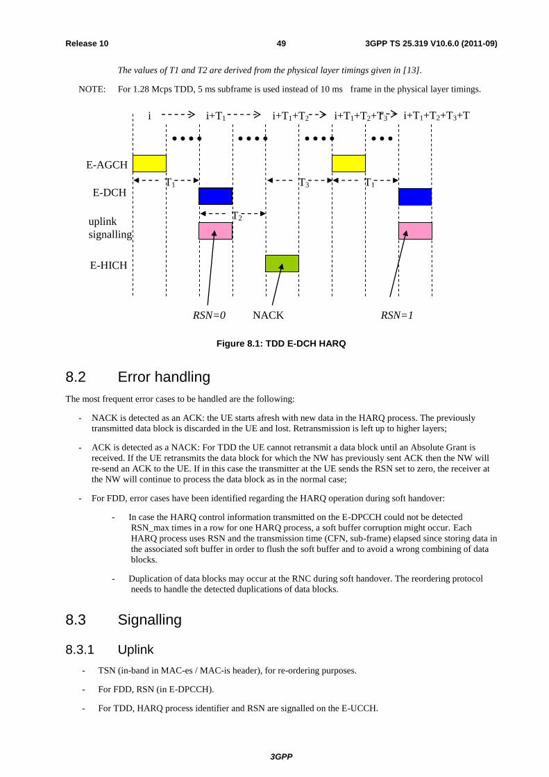
3GPP
3GPP TS 25.319 V10.6.0 (2011-09) 49 Release 10
The values of T1 and T2 are derived from the physical layer timings given in [13].
NOTE: For 1.28 Mcps TDD, 5 ms subframe is used instead of 10 ms frame in the physical layer timings.
E-AGCH
E-DCH
uplink
signalling
i i+T1
E-HICH
RSN=0
i+T1+T2
NACK
i+T1+T2+T3 i+T1+T2+T3+T
1
T1
T2
T3 T1
RSN=1
Figure 8.1: TDD E-DCH HARQ
8.2 Error handling
The most frequent error cases to be handled are the following:
- NACK is detected as an ACK: the UE starts afresh with new data in the HARQ process. The previously
transmitted data block is discarded in the UE and lost. Retransmission is left up to higher layers;
- ACK is detected as a NACK: For TDD the UE cannot retransmit a data block until an Absolute Grant is
received. If the UE retransmits the data block for which the NW has previously sent ACK then the NW will
re-send an ACK to the UE. If in this case the transmitter at the UE sends the RSN set to zero, the receiver at
the NW will continue to process the data block as in the normal case;
- For FDD, error cases have been identified regarding the HARQ operation during soft handover:
- In case the HARQ control information transmitted on the E-DPCCH could not be detected
RSN_max times in a row for one HARQ process, a soft buffer corruption might occur. Each
HARQ process uses RSN and the transmission time (CFN, sub-frame) elapsed since storing data in
the associated soft buffer in order to flush the soft buffer and to avoid a wrong combining of data
blocks.
- Duplication of data blocks may occur at the RNC during soft handover. The reordering protocol
needs to handle the detected duplications of data blocks.
8.3 Signalling
8.3.1 Uplink
- TSN (in-band in MAC-es / MAC-is header), for re-ordering purposes.
- For FDD, RSN (in E-DPCCH).
- For TDD, HARQ process identifier and RSN are signalled on the E-UCCH.

3GPP
3GPP TS 25.319 V10.6.0 (2011-09) 50 Release 10
8.3.2 Downlink
In the downlink, a report is used to indicate either ACK (positive acknowledgement) or NACK (negative
acknowledgement).
9 Node B controlled scheduling
9.1 General principle
The Node B controlled scheduling is based on uplink and downlink control together with a set of rules on how the
UE shall behave with respect to this signaling.
In the downlink, a resource indication (Scheduling Grant) is required to indicate to the UE the maximum amount of
uplink resources it may use. For FDD Dual Cell E-DCH operation, a resource indication (Scheduling grant) for each
Activated Uplink Frequency is required to indicate to the UE the maximum amount of uplink resources it may use
on the corresponding uplink frequency. For 1.28 Mcps TDD Multi-Carrier E-DCH operation, a resource indication
(Scheduling grant) for each uplink carrier is required to indicate to the UE the maximum amount of uplink resources
it may use on the same uplink carrier. When issuing Scheduling Grants, the Node B may use QoS-related
information provided by the SRNC (see subclause 11.1.1) and from the UE in Scheduling Requests (see subclause
9.3.1). For FDD, the E-AGCH is used for collision resolution for UE's in CELL_FACH. For FDD, the Node B uses
a resource indication (Absolute Grant) for resource release of a common E-DCH resource for UEs in CELL_FACH.
For 1.28Mcps TDD, the E-AGCH is used for common E-RNTI collision resolution for UEs in CELL_FACH.
Unless otherwise specified, the following procedures are run independently for each Activated Uplink Frequency.
For each uplink frequency, the UE has a serving E-DCH cell, and a serving E-DCH RLS. It may also have non-
serving E-DCH cells and non-serving E-DCH RL(s).
For 1.28 Mcps TDD Multi-Carrier E-DCH operation, unless otherwise specified, the following procedures are run
independently for each uplink carrier. For all uplink carriers, the UE has a serving E-DCH cell.
The Scheduling Grants have the following characteristics:
- Scheduling Grants are only to be used for the E-DCH TFC selection algorithm (i.e. they do not influence the
TFC selection for the DCHs);
- For FDD, Scheduling Grants control the maximum allowed E-DPDCH/DPCCH power ratio of the active
processes. For the inactive processes, the power ratio is 0 and the UE is not allowed to transmit scheduled
data;
- For TDD, Scheduling Grants control the maximum allowed rate to be used in E-TFC selection according to
information received in the Absolute Grant;
- For FDD, Scheduling Grants provide collision resolution information and common E-DCH resource release
commands for UEs in CELL_FACH.
- For 1.28Mcps TDD, Scheduling Grants provide common E-RNTI collision resolution information.
- All grants are deterministic;
- Scheduling Grants can be sent once per TTI or slower;
- There are two types of grants:
- The Absolute Grants provide an absolute limitation of the maximum amount of UL resources the UE may
use. In CELL_FACH (FDD only), Absolute Grants also provide collision resolution information and
common E-DCH resource release requests. In CELL_FACH (1.28Mcps TDD only), Absolute Grants also
provide common E-RNTI collision resolution information.
- The Relative Grants (FDD only) increase or decrease the resource limitation compared to the previously
used value;
- Absolute Grants are sent by the Serving E-DCH cell:

3GPP
3GPP TS 25.319 V10.6.0 (2011-09) 51 Release 10
- They are valid for one UE;
- For FDD they may also be valid for a group of UEs or for all UEs;
- The UE identity to be used in the Serving E-DCH cell, the E-RNTI, is signalled to the UE via RRC;
- For 1.28Mcps TDD, a group of common E-RNTIs are allocated to each E-RUCCH for CCCH
transmission. When initiating the CCCH transmission, UE selects an E-RUCCH and accordingly an E-
RNTI related to the E-RUCCH.
- For FDD, the Absolute Grant contains:
- the identity (E-RNTI) of the UE (or group of UEs) for which the grant is intended (through an ID-
specific CRC attachment);
- the maximum power ratio the UE is allowed to use, on 5 bits;
- in case of 2ms TTI an HARQ process activation flag indicating if the Primary Absolute Grant
activates or deactivates one or all HARQ processes. That bit is also used to switch the UE from its
primary E-RNTI to its secondary E-RNTI for both the 2ms and the 10ms TTI. When the E-DCH is
configured with a 10ms TTI the flag shall always indicate that the Absolute Grant Scope is set to all
HARQ processes. For Secondary Absolute Grants the flag shall always indicate that the Absolute
Grant Scope is set to all HARQ processes in this version of the protocol.
- For TDD, the Absolute Grant contains:
- details of the physical resources to be used for transmission
- The grant value – maximum transmit power per resource unit (per slot). The grant value is
indicated in form of the ratio of the maximum expected E-PUCH received power per resource unit
(per slot) to Pe-base via E-AGCH from Node B.
- Timeslots
- Channelisation code
- Resource duration
- E-HICH Indicator(EI), which is used to inform UE which E-HICH the feedback info is carried
on(1.28Mcps TDD only)
- E-UCCH Number Indicator(ENI), which is used to indicate the detailed number of E-
UCCH(1.28Mcps TDD only)
- For FDD, Group Identities are supported. Group identities or dedicated identities are not distinguished by
the UE. It is up to UTRAN to allocate the same identity to a group of UEs;
- For FDD, up to two identities (E-RNTIs), one primary and one secondary, can be allocated to a UE at a
time. In that case, both identities shall use the same E-AGCH channel. The allocation is done by the
Node-B and sent by the SRNC in RRC. No secondary E-RNTI is allocated in CELL_FACH.
- For TDD, one identity (E-RNTI) is allocated to a UE at any time. This allocation is performed by the
Node B and is sent to the UE by the SRNC (via RRC).
- The identity consists of 16 bits;
- For FDD:
- Relative Grants (updates) may be sent by the Serving and Non-Serving Node-Bs as a complement
to Absolute Grants:
- The UE behaviour is exactly the same for Relative Grants for one UE, for a group of UEs and for
all UEs;
- The Relative Grant from the Serving E-DCH RLS can take one of the three values: "UP", "HOLD"
or "DOWN";

3GPP
3GPP TS 25.319 V10.6.0 (2011-09) 52 Release 10
- The Relative Grant from the Non-serving E-DCH RL can take one of the two values: "HOLD" or
"DOWN". The "HOLD" command is sent as DTX. The "DOWN" command corresponds to an
"overload indicator";
- For each UE, the non-serving Node-B operation is as follows:
- If the Node-B could not decode the E-DPCCH/E-DPDCH for the last n1 TTIs (where n1 is TBD)
because of processing issue, it shall notify the SRNC;
- The non-serving Node-B is allowed to send a "DOWN" command only for RoT reasons (see
conditions for sending "DOWN" command in subclause 14.1) and not because of lack of internal
processing resources.
- For TDD:
- An Absolute Grant is sent via one of a set of E_AGCHs
- For each frame, a UE is required to monitor a set of E-AGCHs
- An Absolute Grant is received by the UE if it decodes it using the E-RNTI that it has been
allocated
- Details of the set of E-AGCHs to be monitored are signalled to the UE via RRC
9.2 UE scheduling operation
9.2.1 Grants from the Serving RLS
9.2.1.1 FDD
The UE shall be able to receive Absolute Grants from the Serving E-DCH cell and Relative Grants from the Serving
E-DCH RLS. For Dual Cell E-DCH operation, the UE shall be able to receive Absolute Grants from the Serving E-
DCH cell on each Activated Uplink Frequency and Relative Grants from the Serving E-DCH RLS on each
Activated Uplink Frequency.
The following procedures are run independently for each Activated Uplink Frequency.
The UE shall handle the Grant from the Serving E-DCH RLS as follows:
- If the UE in CELL_FACH is transmitting DTCH/DCCH:
- If an Absolute Grant was received within the collision resolution phase after starting transmitting on the
granted common E-DCH resource:
- stop including its E-RNTI in the MAC-i PDU;
- Else
- stop any E-DPCCH and E-DPDCH transmission, stops any E-AGCH and E-HICH reception, resets
MAC-is/i, releases all E-DCH HARQ resources and no longer considers any radio link to be the
serving E-DCH radio link.
- If an Absolute Grant was received with value set to 'INACTIVE':
- stop any E-DPCCH and E-DPDCH transmission, stops any E-AGCH and E-HICH reception, resets
MAC-is/i, releases all E-DCH HARQ resources and no longer considers any radio link to be the serving
E-DCH radio link.
- The UE maintains a "Serving Grant" (SG);
- The SG is used in the E-TFC selection algorithm as the maximum allowed E-DPDCH/DPCCH power ratio
for the transmission of scheduled data in active HARQ processes;

3GPP
3GPP TS 25.319 V10.6.0 (2011-09) 53 Release 10
- Each Absolute Grant and Relative Grant is associated with a specific uplink E-DCH TTI i.e. HARQ process
and HARQ entity. This association is implicitly based on the timing of the E-AGCH and E-RGCH (see [3]).
The timing is tight enough that this relationship is un-ambiguous;
- The SG is updated according to the following algorithm, regardless of the transmission/retransmission status
of the HARQ process. The SG is not used for the E-TFC selection algorithm if the HARQ process is in
retransmission;
- When receiving an "Absolute Grant" on the E-AGCH of the serving E-DCH cell:
- Primary Absolute Grants always affect the SG;
- Secondary Absolute Grants only affect the SG if the last Primary Absolute Grant was set to 'INACTIVE'
and, in case of 2ms TTI, the process activation flag was set to 'All' (transition trigger), or if the latest
Absolute Grant that affected the SG was the Secondary one. When transition to the secondary E-RNTI is
triggered, UE shall update the SG with the latest received Absolute Grant on the secondary E-RNTI (UE
shall listen to both E-RNTIs in parallel, if both E-RNTIs are configured);
- In case of 10ms TTI, SG is set to the received value if the grant value is different from 'INACTIVE';
- In case of 2ms TTI and a Primary Absolute Grant was received:
- If the received value is different from 'INACTIVE', the SG is set to that value and the following
activation mechanism is applied to processes that are not disabled as per L3 signalling:
- In case of an AG associated to an inactive process, the process activation flag indicates whether
all processes or only this particular process becomes active;
- In case of an AG associated to an active process, the process activation flag will indicate whether
all processes become active ('all') or the activation status of the processes is not changed
('single');
- If the received value is 'INACTIVE', the UE behaviour depends on the process activation flag:
- If the flag is set to 'single', this active process becomes inactive;
- If the activation flag is set to 'All' and the secondary E-RNTI is configured:
- All L3-enabled processes that are deactivated become active.
- If the activation flag is set to 'All' and the secondary E-RNTI is not configured:
- All L3-enabled processes are deactivated (if a process was inactive it remains inactive, if a
process was active it becomes inactive).
- In case of 2ms TTI and a Secondary Absolute Grant was received:
- In case the Secondary Absolute Grant affects the SG, the SG is set to the received value.
- If no "Absolute Grant" is received by the UE in a TTI and the last SG update was due to a Primary Absolute
Grant from the E-AGCH or from RRC signalling, then the UE shall follow the "Relative Grant" of the
Serving E-DCH RLS:
- A Serving Relative Grant is interpreted relative to the UE power ratio in the previous TTI for the same
hybrid ARQ process as the transmission which the Relative Grant will affect (see figure 9.2.1-1);
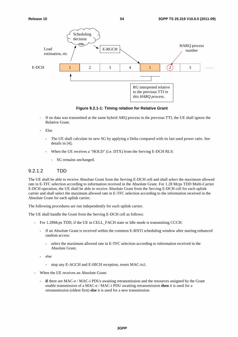
3GPP
3GPP TS 25.319 V10.6.0 (2011-09) 54 Release 10
1 2 3 4 1 2 3
E-RGCH
E-DCH
HARQ process
number
Scheduling
decision
Load
estimation, etc
RG interpreted relative
to the previous TTI in
this HARQ process.
Figure 9.2.1-1: Timing relation for Relative Grant
- If no data was transmitted at the same hybrid ARQ process in the previous TTI, the UE shall ignore the
Relative Grant.
- Else
- The UE shall calculate its new SG by applying a Delta compared with its last used power ratio. See
details in [4];
- When the UE receives a "HOLD" (i.e. DTX) from the Serving E-DCH RLS:
- SG remains unchanged.
9.2.1.2 TDD
The UE shall be able to receive Absolute Grant from the Serving E-DCH cell and shall select the maximum allowed
rate in E-TFC selection according to information received in the Absolute Grant. For 1.28 Mcps TDD Multi-Carrier
E-DCH operation, the UE shall be able to receive Absolute Grant from the Serving E-DCH cell for each uplink
carrier and shall select the maximum allowed rate in E-TFC selection according to the information received in the
Absolute Grant for each uplink carrier.
The following procedures are run independently for each uplink carrier.
The UE shall handle the Grant from the Serving E-DCH cell as follows:
- For 1.28Mcps TDD, if the UE in CELL_FACH state or Idle mode is transmitting CCCH:
- If an Absolute Grant is received within the common E-RNTI scheduling window after starting enhanced
random access:
- select the maximum allowed rate in E-TFC selection according to information received in the
Absolute Grant.
- else
- stop any E-AGCH and E-HICH reception, resets MAC-is/i.
- When the UE receives an Absolute Grant:
- if there are MAC-e / MAC-i PDUs awaiting retransmission and the resources assigned by the Grant
enable transmission of a MAC-e / MAC-i PDU awaiting retransmission then it is used for a
retransmission (oldest first) else it is used for a new transmission.
3GPP
3GPP TS 25.319 V10.6.0 (2011-09) 55 Release 10
9.2.2 Grants from the Non-serving RL (FDD only)
Non-serving RLs may only send Relative Grants to the UE. For Dual Cell E-DCH operation, the UE may have Non-
serving RLs for each Activated Uplink Frequency. The following procedure is run independently for each Activated
Uplink Frequency.
The UE shall handle the RG from these non-serving E-DCH RLs as follows:
- When the UE receives a "DOWN" from at least one Non-serving E-DCH RL, it is interpreted relative to the
UE power ratio in the previous TTI for the same hybrid ARQ process and entity as the transmission which
the Relative Grant will affect (see figure 9.2.1-1). The UE shall calculate its new SG, see details in [4].;
- Following reception of a non-serving 'DOWN', UE shall ensure that its SG is not increased (due to E-AGCH
or E-RGCH signalling) during one HARQ cycle.
9.2.3 Reception of Grants from both the Serving RLS and Non-serving RL(s) (FDD only)
In the case of a UE receiving grants from both the Serving RLS and Non-Serving RL(s), the UE behaviour is the
following:
- When the UE receives a scheduling grant from the Serving E-DCH RLS and a "DOWN" command from at
least one Non-Serving E-DCH RL:
- new SG is set to the minimum between the resulting SG from the non-serving E-DCH RL and the
resulting SG from the serving RLS.
9.3 Signalling
9.3.1 Uplink
For the UE to request resources from the Node B(s), Scheduling Requests will be transmitted in the uplink in the
form of Scheduling Information and Happy Bit (FDD only). The Scheduling information will be transmitted for the
logical channels for which RRC configured that reporting needed to be made. For FDD, the Happy Bit shall always
be included in the E-DPCCH, whenever the E-DPCCH is transmitted.
9.3.1.1 Scheduling information
9.3.1.1.1 Content
The UE includes the following in the Scheduling Information (only taking into account the logical channels for
which RRC configured that reporting was required and always excluding logical channels mapped on non-scheduled
MAC-d flows):
- Logical channel ID of the highest priority channel with data in buffer, on 4 bits. The logical channel ID
field identifies unambigiouly the highest priority logical channel with available data and QoS
information related to this indicated logical channel;
- UE Buffer occupancy (in Bytes):
- Buffer status for the highest priority logical channel with data in buffer, on 4 bits, as a fraction
of the total reported buffer;
- Total buffer status, on 5 bits;
- UE Power Headroom (UPH): For FDD, the UPH field indicates the ratio of the maximum UE
transmission power and the corresponding DPCCH code power defined in [7]. For TDD, the UPH field
indicates the ratio of the maximum power and the calculated UE transmit power as defined in [10] with
e = 0. The UPH field is 5 bits.
- For TDD: Path Loss:

3GPP
3GPP TS 25.319 V10.6.0 (2011-09) 56 Release 10
- Information derived from measurements of serving cell and neighbour cell's RSCP (5 bits);
9.3.1.1.2 Triggers
In the case where the UE is not allowed to transmit scheduled data (because it has no Serving Grant available or it
has received an Absolute Grant preventing it from transmitting in any process) and it has Scheduled data to send on
a logical channel for which Scheduling Information shall be reported:
- For FDD:
- Scheduling Information shall be sent to the Serving E-DCH RLS in a MAC-e / MAC-i PDU;
- Periodic reporting to protect against NACK-to-ACK misinterpretation;
- Scheduling Information could be sent alone, or with non-scheduled data, if such exist;
- Scheduling Information will also be triggered if higher priority data arrives in buffer.
- For 3.84 Mcps and 7.68 Mcps TDD:
- Scheduling Information shall be sent to the Node B on the E-RUCCH (E-DCH Random access Uplink
Control Channel)
- Buffer Information, Physical Layer Information plus the E-RNTI is sent on the E-RUCCH
- Scheduling information may also be sent with non-scheduled data.
In the case where the UE is allowed to transmit scheduled data and it has Scheduled data to send on a logical
channel for which Scheduling Information shall be reported:
- it shall send the Scheduling Information to the Serving E-DCH RLS in the MAC-e / MAC-i PDU;
- the Scheduling Information is sent periodically (period defined by RRC);
- For FDD and 1.28Mcps TDD, in CELL_FACH and IDLE mode, Scheduling Information shall be sent
to report an empty buffer status.
The details on how Scheduling Information is included in the MAC-e / MAC-i PDU can be found in [4].
- For 1.28 Mcps TDD:
- In the case where the UE has no Grant and it has data to send, or an E-DCH serving cell change occurs
with the TEBS larger than zero:
- Buffer Information and Physical Layer Information plus the E-RNTI shall be sent to the Node B on
the E-RUCCH (E-DCH Random access Uplink Control Channel).
- In the case where the UE has a Grant and has data to send:
- It shall send Buffer Information and Physical Layer Information to the Node B in the MAC-e / MAC-i
PDU.
- if the higher priority data arrives:
- if there is a Grant available for a new MAC-e / MAC-i PDU transmission, the Scheduling
Information should be sent and included in the MAC-e / MAC-i PDU.
- otherwise, the Scheduling Information should be sent on the periodic reporting mechanism.
- In the case where UE transits from having a Grant to not having a Grant and has data to send, a timer
T_WAIT is provided as a delay time to send buffer information mapped on E-RUCCH (T_WAIT is
configured by RRC,default value is 8TTIs):
- When UE has sent data on E-PUCH in the last TTI before the current Grant expires:
- The timer T_WAIT shall be started.
3GPP
3GPP TS 25.319 V10.6.0 (2011-09) 57 Release 10
- When a grant is received before the timer expires:
- The timer shall be stopped.
- When the timer T_WAIT expires:
- A new E-RUCCH transmission shall be made (the timer T_WAIT shall be stopped).
- In the case where the UE is only configured with non-scheduled transmission and without scheduled
transmission, the Scheduling Information shall be included in MAC-e / MAC-i PDU due to the
quantization of the transport block sizes that can be supported or upon the expiration of the timer T-SI-
NST if configured, details in [4].
For UE in CELL_FACH state with E-DCH transmission, control of E-RUCCH transmission procedure triggered by
different events shall be co-operated as below:
- In case Cell Reselection Indication via E-RUCCH is involved:
- During the E-RUCCH transmisson procedure triggered by Cell Reselection Indication ongoing, E-
RUCCH transmission triggered by any event shall not be initiated and the corresponding events shall be
ignored.
- During the E-RUCCH transmisson procedure triggered by events other than Cell Reselection Indication
ongoing, if Cell Reselection Indication via E-RUCCH needs to be sent, any event which would initiate E-
RUCCH transmission shall be cancelled.
- Else
- During the E-RUCCH transmisson procedure triggered by Scheduling Information reporting ongoing, E-
RUCCH transmission triggered as a response to synchronization establishment command shall not be
initiated and the newly triggered event shall be ignored.
- During the E-RUCCH transmisison procedure triggered as response to synchronization establishment
command, if Scheduling Information reporting via E-RUCCH is needed, the E-RUCCH transmission
shall be cancelled and Scheduling Information reporting via E-RUCCH shall be initiated with newly
updated field of Scheduling Information according to the UE’s current status.
9.3.1.1.3 Transmission and Reliability scheme
Two transmission mechanisms are defined, depending on whether the Scheduling Information is transmitted alone,
or with data (scheduled and/or non-scheduled):
1. When the Scheduling Information is sent alone:
For FDD:
- The power offset is configured by RRC and the maximum number of re-transmissions is
defined by the standard;
- HARQ (re)transmissions are performed until an ACK from the RLS containing the serving cell
is received or until the max number of transmissions is reached.
For TDD:
- Scheduling Information sent via the E-RUCCH (no Scheduling Grant) is transmitted at
appropriate power and forward error correction, as defined by physical layer specifications. If
the UE does not receive a response in the form of an Absolute Grant is received then the UE is
required to resend Scheduling Information.
- For 1.28 Mcps TDD, Scheduling Information sent via MAC-e / MAC-i PDU alone is
transmitted by applying the power offset, the retransmission timer and the maximum number of
re-transmissions configured by RRC. HARQ (re)transmissions are performed until an ACK is
received, or until the max number of transmissions is reached or the retransmission timer
expires.
3GPP
3GPP TS 25.319 V10.6.0 (2011-09) 58 Release 10
2. When Scheduling Information is sent with data:
- Use the HARQ power offset attribute of the highest priority data, and the maximum number of
transmissions among all the considered HARQ profiles associated to the MAC-d flows for the
MAC-e / MAC-i PDU to be transmitted;
- HARQ (re)transmissions are performed until an ACK is received, or until the max number of
transmissions is reached.
- For FDD, if the UE receives an ACK from an RLS not containing the serving cell
for a packet that includes scheduling information which was triggered by an event or
a timer as per section 9.3.1.1.2, it flushes the packet and includes the scheduling
information with new data payload in the following packet.
For 3.84 Mcps and 7.68 Mcps TDD:
- A timer value T-RUCCH is used to control retransmission of buffer information if there has been no grant
received. The timer TR manages retransmission of scheduling information if the UE does not receive a grant
following an E-RUCCH transmission.
- Even when the scheduling information is sent on E-PUCH it is possible that the Node B may send a NACK
(indicating that the buffer information was not correctly decoded) which the UE wrongly interprets as an
ACK. Therefore, timers are also required to control retransmission of scheduling information sent on E-
PUCH.
(T-RUCCH is configured by RRC, in Radio Bearer Setup Request, default value is 200 ms).
- When the aggregate buffer volume transitions from zero to greater than zero or the scheduling information
delay timer ≥ T-SCHED + T-RUCCH / 2:
- E-RUCCH shall be sent (carrying scheduling information) and TR shall be started/restarted.
- When timer TR ≥ T-RUCCH a new E-RUCCH transmission shall be made (the timer is restarted) once a
successful draw has been made using the E-RUCCH persistence value.
- Timer TR is stopped (if running) when a grant is received.
- The scheduling information delay timer is restarted whenever scheduling information is sent on the E-PUCH.
For 1.28 Mcps TDD
- A timer T_RUCCH and a maximum number of transmissions N_RUCCH are used to control the
retransmission of scheduling information, if there has been no Grant received following an E-RUCCH
transmission. The maximum number of transmissions N_RUCCH is a mechanism to prevent the redundant
transmission. T_RUCCH and N_RUCCH will be configured by higher layer and act as follows.
- A periodic Timer T-SI (defined by RRC) is used to avoid long pause duration of scheduling information
reporting when scheduling information is sent on E-PUCH.
- When the timer T_WAIT expires or when the SI is triggered and there is no Grant available for new MAC-e /
MAC-i PDU transmission in current TTI or in Extended Estimation Window (if configured by RRC):
- the UE sends information mapped on E-RUCCH;
- the timer T_RUCCH shall be started and a counter is set to 1.
- When a grant is received:
- the timer T_RUCCH shall be stopped and not be restarted, the counter shall be reset.
- When the timer T_RUCCH expires:
- if the counter is not greater than N_RUCCH:
- a new E-RUCCH transmission shall be made (restart the timer and increment the counter).
- else
3GPP
3GPP TS 25.319 V10.6.0 (2011-09) 59 Release 10
- the timer T_RUCCH shall be stopped and not be restarted, the counter shall be reset.
- Another hysteresis Timer with the value of N-RUCCH times of T-RUCCH period shall be started,
upon the hysteresis Timer expires and still no Grant has been received for the whole time duration
since the last E-RUCCH transmission, a "Radio link failure" shall be triggered and reported.
- A periodic timer T-SI-NST (optionally defined by RRC) may be used to avoid long pause duration of
scheduling information reporting when the UE is only configured with non-scheduled transmission and
without scheduled transmission.
9.3.1.2 Happy bit of E-DPCCH (FDD only)
One bit of the E-DPCCH is used to indicate whether or not the UE is satisfied ('happy') with the current Serving
Grant. This bit shall always be present during uplink transmission of E-DPCCH.
The UE shall indicate that it is 'unhappy' if the following criteria are met:
1) UE is transmitting as much scheduled data as allowed by the current Serving Grant; and
2) UE has enough power available to transmit at higher data rate; and
3) Total buffer status would require more than Happy_Bit_Delay_Condition ms to be transmited with the
current Serving_Grant × the ratio of active processes to the total number of processes.
The first criteria is always true for a deactivated process and the ratio of the third criteria is always 1 for 10ms
TTI.
Otherwise, the UE shall indicate that it is 'happy'.
9.3.2 Downlink
For each UE, there can only be one Absolute Grant transmitted by the serving E-DCH cell using the E-AGCH.
For 1.28 Mcps TDD Multi-Carrier E-DCH operation, for each UE, there can be one Absolute Grant transmitted by
the serving E-DCH cell using the E-AGCH for each uplink carrier.
For FDD:
- For each UE, there can be one Relative Grant transmitted per Serving RLS and one per Non-serving RL
from the E-DCH active set cells.
- The channel(s) (one per cell) on which the Relative Grant is transmitted is(are) signalled separately to each
UE (this allows for the same channel to be monitored by multiple UEs if UTRAN decides so).
10 Non-scheduled transmissions
When non-scheduled transmission is configured by the SRNC, the UE is allowed to send E-DCH data at any time,
up to a configured number of bits, without receiving any scheduling command from the Node B. Thus, signalling
overhead and scheduling delay are minimized.
Typical examples of data that may use non-scheduled transmission are the SRBs and GBR services.
For FDD and 1.28Mcps TDD, in CELL_FACH state and Idle mode, non-scheduled transmission is not supported.
Non-scheduled transmissions have the following characteristics:
- Non-scheduled transmissions are defined per MAC-d flow;
- The resource for non-scheduled transmission is given by the SRNC in terms of maximum number of bits that
can be included in a MAC-e / MAC-i PDU, and is called non-scheduled grant;
- Scheduled logical channels cannot use a non-scheduled grant.

3GPP
3GPP TS 25.319 V10.6.0 (2011-09) 60 Release 10
- For TDD a non scheduled grant is defined by:
- The codes and timeslots available for transmission in TTIs designated for unscheduled use
- The frames designated for unscheduled use (specified by means of start frame number, repetition
period and repetition length)
- For FDD:
- UTRAN can restrict a non-scheduled MAC-d flow to use a limited number of HARQ processes in
case of 2ms TTI;
- UTRAN can reserve some HARQ processes for non-scheduled transmission (i.e. scheduled data
cannot be sent using these processes, they are considered disabled) in case of 2ms TTI;
- Reserving certain HARQ processes for non-scheduled transmission and restricting non-scheduled
transmission to specific HARQ processes are scheduling mechanisms under the control of the
serving cell Node B; Serving cell Node B signals the applicability of allocated resources for non-
scheduled/scheduled transmission to HARQ processes according to the restriction/reservation
decision to S-RNC, which informs other Node Bs in the E-DCH active set.
- Multiple non-scheduled MAC-d flows may be configured in parallel by the SRNC;
- The UE is then allowed to transmit non-scheduled transmissions up to the sum of the non-
scheduled grant if multiplexed in the same TTI;
- For TDD, HARQ process identifiers 0 – 3 are reserved for scheduled transmissions and HARQ process
identifiers 4 – 7 are reserved for non-scheduled transmissions;
- For FDD, Scheduled grants will be considered on top of non-scheduled transmissions;
- Logical channels mapped on a non-scheduled MAC-d flow cannot transmit data using a Scheduling Grant;
- Logical channels mapped on a non-scheduled MAC-d flow can only transmit up to the non-scheduled grant
configured for that MAC-d flow;
- The multiplexing list restricting the set of HARQ profiles that can be used by a given logical channel will
apply both for scheduled and non-scheduled logical channels;
- Logical channels will be served in the order of their priorities until the non-scheduled grant and scheduled
grants are exhausted, or the maximum transmit power is reached;
- When multiple logical channels are assigned the highest priority, the selection of the HARQ
profile for these logical channels is not specified.
11 QoS control
11.1 General Principle
The QoS of ongoing flows mapped on E-DCH for a UE is maintained by the serving Node B and by the UE. The
Node B controls the resources allocated to a UE versus other UEs by means of scheduling as specified in clause 9.
The UE controls the QoS of all its logical channels mapped on E-DCH by means of E-TFC selection as specified in
subclause 11.2, and by HARQ operation, specified in clause 8.
In addition to these mechanisms, guaranteed bit rate services for MAC-d flows are also supported through non-
scheduled transmission. In CELL_DCH, a flow using non-scheduled transmission is defined by the SRNC and
provided in the UE and in the Node B. Details on non-scheduled transmission can be found in section 10. For FDD
and 1.28Mcps TDD, in CELL_FACH state and Idle mode, a flow using scheduled transmission is defined by the
SRNC and CRNC and provided in the UE and in the Node B.
3GPP
3GPP TS 25.319 V10.6.0 (2011-09) 61 Release 10
11.1.1 QoS configuration principles
RAB attributes are available in the SRNC according to R'99 principles. To enable QoS control for the E-DCH, QoS-
related information is made available in the UE and in the Node B as outlined below.
To the UE, the following QoS-related information is provided from the SRNC to enable QoS-based E-TFC
selection, multiplexing of logical channels in MAC-e / MAC-i PDUs, and HARQ operation:
- Logical channel priority for each logical channel (as in Rel-5);
- Mapping between logical channel(s) and MAC-d flow(s) (as in Rel-5);
- Allowed MAC-d flow combinations in one MAC-e / MAC-i PDU;
- for FDD, power offset for reference E-TFC(s). The UE then calculates the power offsets for its other E-
TFCs so that the quality (protection of a MAC-e / MAC-i PDU) when using any of the E-TFCs is
identical to that of the reference E-TFC(s);
- for 1.28Mcps TDD, power offset for reference coderate(s). The UE then calculates the power offset for
its E-TFC so that the quality (protection of a MAC-e / MAC-i PDU) when using any of the E-TFCs is
identical to that of the reference coderate(s);
- The E-DPCCH power offset (FDD only). This is used to set the protection level for E-DPCCH
transmissions;
- The E-RUCCH power offset (3.84 Mcps and 7.68 Mcps TDD only): This is used to set the power level
for E-RUCCH transmissions;
- E_UCCH protection level (3.84 Mcps and 7.68 Mcps TDD only): This is set to the FEC protection level
for E-UCCH transmissions;
- HARQ profile per MAC-d flow. One HARQ profile consists of a power offset attribute and a maximum
number of transmissions attribute and for 1.28 Mcps TDD a retransmission timer attribute. The power
offset attribute is used in E-TFC selection to regulate the BLER operating point for the transmission. The
maximum number of transmissions attribute is used in the HARQ operation to regulate maximal latency
and residual BLER of MAC-d flows. The retransmission timer (1.28 Mcps TDD only) is used to control
the retransmission of a MAC-e / MAC-i PDU;
- The non-scheduled grant (only for MAC-d flows that are configured for non-scheduled transmission).
In CELL_DCH, to the Node Bs in the E-DCH active set and Secondary E-DCH active set when Dual Cell E-DCH
operation is configured, the following QoS-related parameters are provided by the SRNC to enable scheduling and
resource reservation:
- Power offsets for reference E-TFC(s). The Node B then calculates the power offsets for the other E-
TFCs. This information is used whenever the nodeB needs to convert between rate and power in its
resource allocation operation;
- For FDD, E-DPCCH power offset. This is used whenever the Node B needs to convert between rate
and power in its resource allocation operation;
- For 3.84 Mcps and 7.68 Mcps TDD, E-RUCCH power offset and E-UCCH FEC protection level.
- HARQ profile per MAC-d flow. One HARQ profile consists of a power offset attribute and a
maximum number of transmissions attribute and for 1.28 Mcps TDD a retransmission timer attribute.
The power offset attribute is used whenever the Node B needs to convert between rate and power in its
resource allocation operation;
- Guaranteed bit rate for logical channels that carry guaranteed bit rate services. It is used to allocate
grants to UEs;
- The non-scheduled grant for MAC-d flows that are configured for non-scheduled transmission. It is
used for the Node B to reserve sufficient amount of resources. The need for additional mechanisms to
optimize the Node-B hardware is FFS (e.g. the UE may tell the Node-B ahead that a non-scheduled
transmission is coming);

3GPP
3GPP TS 25.319 V10.6.0 (2011-09) 62 Release 10
- Maximum UL UE power, as a minimum of the UE maximum transmit power (as per UE power class)
and maximum allowed UL Tx power configured by UTRAN. This information is only sent to the
serving cell's nodeB (whether the max UL UE power can also be signalled to other nodeBs in the
active set or not is FFS);
- Scheduling priority per logical channel of logical channels mapped to E-DCH and the corresponding
mapping between logical channel identifier and DDI value. This information enables Node B to
consider QoS related information of the logical channels for efficient scheduling.
For FDD, in CELL_FACH state and Idle mode, to the Node Bs in the Serving E-DCH cell, the following QoS-
related parameters are provided by the CRNC to enable scheduling and resource reservation:
- Power offsets for reference E-TFC(s). The Node B then calculates the power offsets for the other E-TFCs.
This information is used whenever the Node B needs to convert between rate and power in its resource
allocation operation;
- E-DPCCH power offset. It is used whenever the Node B needs to convert between rate and power in its
resource allocation operation;
- HARQ profile per MAC-d flow. One HARQ profile consists of a power offset attribute and a maximum
number of transmissions attribute. The power offset attribute is used whenever the Node B needs to convert
between rate and power in its resource allocation operation;
- Maximum UL UE power, as a minimum of the UE maximum transmit power (as per UE power class) and
maximum allowed UL Tx power configured by UTRAN.
- Maximum duration of collision resolution phase for DTCH/DTCCH transmission. If the maximum duration
of the collision resolution phase has expired, the Node B is aware that the common E-DCH resource is used
by at most one UE. This information enables the Node B to consider QoS related information for requesting
state transition to CELL_DCH.
- Maximum duration of common E-DCH resource allocation for CCCH transmission.
For 1.28Mcps TDD, in CELL_FACH state and Idle mode, to the Node Bs in the Serving E-DCH cell, the following
QoS-related parameters are provided by the CRNC to enable scheduling and resource reservation:
- Power offsets for reference coderate(s). The Node B then calculates the power offsets for the other coderates.
This information is used whenever the Node B needs to convert between rate and power in its resource
allocation operation;
- HARQ profile per MAC-d flow. One HARQ profile consists of a power offset attribute, a maximum number
of transmissions attribute and a retransmission timer attribute. The power offset attribute is used whenever
the Node B needs to convert between rate and power in its resource allocation operation;
11.2 TFC and E-TFC selection
For FDD:
- Logical channels mapped on the DCHs are always prioritised over those mapped on E-DCH.
- The principle of the TFC selection across E-DCH and DCH is the following:
- The UE performs TFC restriction for the CCTrCH of DCH type;
- The UE performs the TFC selection for the DCHs;
E-TFC restriction is performed with the following characteristics;
- The E-TFC restriction mechanism is independent of the existing TFC restriction;
- The E-TFC states defined per MAC-d flow are managed independently of the TFC states;
- The UE uses the power offsets for the reference E-TFC(s), the signalled power offset attributes for its MAC-
d flows, the required E-TFC dependent backoff, and the UE remaining power to determine the E-TFC states;

3GPP
3GPP TS 25.319 V10.6.0 (2011-09) 63 Release 10
- For FDD, when the UE has more than one Activated Uplink Frequency, the UE determines the state of each
E-TFC on each uplink frequency, based on the power offsets for the reference E-TFC(s), the signalled power
offset attributes for its MAC-d flows, the required E-TFC dependent backoff, and the maximum power
allowed for UE transmission on that frequency.
- For FDD, the HS-DPCCH, DPCCH, DPDCH and E-DPCCH powers are taken into account when calculating
the remaining power;
- For FDD, if the UE has more than one Activated Uplink Frequency, the power is pre-allocated for all non-
empty non-scheduled flow on the Primary Uplink Frequency.
- For FDD, if the UE has more than one Activated Uplink Frequency, the remaining power, Premaining after
power pre-allocation for all the non-empty non-scheduled MAC-d flows, is split among all the Activated
Uplink Frequencies in proportion to the respective serving grants.
- For FDD, if the UE has more than one Activated Uplink Frequency and E-TFC selection is invoked on only
one frequency, the E-TFC selection behaviour is performed as if only one uplink frequency is activated.
- For FDD, if the UE has more than one Activated Uplink Frequency, the maximum allowed power for UE
transmission on Primary Uplink Frequency is the sum of the power pre-allocated for all non-empty non-
scheduled MAC-d flows and the power Pi as a result of the power splitting for this frequency. For the
Secondary Uplink Frequency, the maximum allowed power for UE transmission is the resulting P i power for
this frequency.
- The result of E-TFC restriction is a state (blocked or supported) per E-TFC and MAC-d flow;
- For FDD:
- The minimum set of E-TFCs is defined as the number of bits that can be transmitted in a TTI independent
of the power situation in the UE, provided there is nothing sent on the DCH, and is configurable from the
RNC as one E-TFC per UE. When there is nothing sent on DCH, the E-TFCs belonging to the minimum
set are in supported state;
- In the case where 2ms TTI is configured, E-TFC selection shall not be performed for TTIs that overlap
with an uplink compressed mode gap;
- The UE performs the E-TFC selection for the E-DCH, taking into account the following rules:
- The E-TFC selection is based on logical channel priorities like in the Release '99, i.e. the UE shall
maximise the transmission of higher priority data;
- The UE shall respect the allowed combinations of MAC-d flows in the same MAC-e / MAC-i PDU;
- The UE shall use the multiplexing list of the different MAC-d flows to see if a certain MAC-d
flow can use the power offset of the highest priority MAC-d flow to be transmitted;
- The supported/blocked E-TFCs for a MAC-e / MAC-i PDU including MAC-d PDUs coming from one or
several MAC-d flows are obtained as follows:
- The UE uses the E-TFC restriction result (i.e. blocked/supported E-TFCs) associated to the MAC-d
flow with the highest priority logical channel in the MAC-e / MAC-i PDU;
- For FDD, if a 10ms TTI E-DPDCH frame that overlaps with a compressed mode gap, the Serving Grant shall
be scaled back according to the procedure described in [4];
- Among the supported E-TFCs, the UE selects the smallest E-TFC that maximises the transmission of data
according to the non-scheduled grant(s) or the serving grant;
- For FDD, when the UE has more than one Activated Uplink Frequency, non-scheduled transmissions are
only allowed on the Primary Uplink Frequency
- For each transmission, the MAC-e / MAC-i entity gives the selected power offset to L1 in addition to the E-
TFC:
3GPP
3GPP TS 25.319 V10.6.0 (2011-09) 64 Release 10
- For FDD, the power offset given to L1 is of E-DPDCH(s) relative to DPCCH;
- For TDD the power offset given to L1 is of E-PUCH(s) transmission power relative to a reference power
level defined as the calculated E-PUCH power level of [10] with e=0;
- In case the maximum UE transmit power is exceeded;
- For FDD, the UE shall scale down the E-DPDCH only on slot level for both initial transmission and
retransmissions. Further details on uplink power reduction mechanisms can be found in [3].
- For TDD, the UE shall scale down all physical channels present.
11.3 Setting of Power offset attributes of MAC-d flows
Power offset attributes of MAC-d flows are part of the HARQ profiles of the MAC-d flow. They are provided by the
UTRAN to the UE according to the following principles:
- For FDD, the DPCCH transmission power is controlled the same way as in Release '99;
- For TDD:
- Power control of the CCTrCH of E-DCH type is based on a combination of open loop power control
component as used in Release '99/4/5/6 and a closed loop TPC component (signalled from Node B to UE
alongside the Absolute Grant).
- For DTCH and DCCH transmission, with each MAC-es / MAC-is PDU transmitted to the SRNC, the Node-
B includes the number of transmissions that have been required to correctly decode the PDU. Also, the
serving NodeB shall send an HARQ failure indication in case of unsuccessful decoding of the E-DCH
payload (see [5]);
- For FDD and 1.28Mcps TDD only, with each MAC-is PDU carrying CCCH data transmitted to the CRNC,
the serving Node-B includes the number of transmissions that have been required to correctly decode the
PDU. Also, the serving NodeB shall send an HARQ failure indication in case of unsuccessful decoding of the
E-DCH payload (see [5]);
- In CELL_DCH, using the information provided by the Node B(s), the SRNC may maintain up to date power
offsets;
- In CELL_DCH, the SRNC may decide to signal to the UE and the Node Bs in the E-DCH active set and
Secondary E-DCH active set when Dual Cell E-DCH operation is configured new values for the power offset
attributes for one (or several) MAC-d flow(s);
12 Signalling parameters
12.1 Uplink signalling parameters
Void.
12.2 Downlink signalling parameters
With RRC signalling, the UE will in addition be informed about:
- The E-RNTI(s) assigned
- The E-HICH configuration
- For FDD, this includes signature sequence number and channelisation code;
- For 3.84 Mcps and 7.68 Mcps TDD, this includes timeslot, channelisation code, midamble and burst type;

3GPP
3GPP TS 25.319 V10.6.0 (2011-09) 65 Release 10
- For 1.28 Mcps TDD:
- In the case of scheduled transmission , a set of E-HICHs can be configured for a UE for each E-DCH
transport channel:
- Including timeslot, channelisation code, midamble;
- The mapping between EI (E-HICH Indicator) and E-HICH physical resource.
- In the case of non-scheduled transmission, only one E-HICH shall be configured for a UE:
- Including timeslot, channelisation code, midamble;
- Index of the pre-defined signature sequence table [10].
- For FDD:
- The E-RGCH configuration
- Including signature sequence number, channelisation code (same as the E-HICH), RG reference step
size for serving RLS, RG step size for non-serving RL and Serving E-DCH RLS ID;
- The E-AGCH configuration
- Including E-RNTI(s) and channelisation code;
- The E-DPCCH configuration
- E-DPCCH/DPCCH Power Offset;
- Threshold (in TTIs) used by the UE when evaluating the time needed to completely empty its
buffers. Used as a conditions for setting the 'happy' bit in E-DPCCH;
- For 3.84 Mcps and 7.68 Mcps TDD:
- T-SCHED
- The set of E-AGCHs configured
- including timeslot and channelisation code, midamble, burst type for each E_AGCH;
- E-UCCH configuration
- FEC protection level
- E-RUCCH configuration
- constant value, persistence scaling, rate matching attribute
- timeslot, midamble, SF16 or SF8, channelisation codes
- T-RUCCH
- The E-PUCH configuration including:
- timeslots assigned to E-PUCH
- identities of the E-PUCH timeslots which are to carry TPC and TFCI bits
- reference Beta values to use:
- for each reference T-TFC a (nominal) beta factor is calculated based on the power offset signalled for
each reference E-TFC via RRC (maximum number of reference E-TFCs is 8 for 16QAM and for
8PSK)
- for each E-PUCH timeslot:
- burst type and midamble to be used
3GPP
3GPP TS 25.319 V10.6.0 (2011-09) 66 Release 10
- minimum code rate and maximum code rate
- For 1.28 Mcps TDD:
- The set of E-AGCHs configured for each E-DCH transport channel
- Including frequency (for Multi-Carrier E-DCH operation), timeslot and channelisation code,
midamble for each E-AGCH
- TPC step size for E-AGCHs
- E-UCCH configuration for non-scheduled transmission
- E-RUCCH configuration
- T_WAIT
- T_RUCCH
- N_RUCCH
- T-SI
- Extended Estimation Window (optional)
- Indicates how many next consecutive 5ms TTIs the UE should estimate whether there is a valid Grant
before sending Scheduling Infomation via E-RUCCH and is used to prevent the UE from sending
unnecessary E-RUCCH especially in case the UE has a potential Grant a short time in the future, e.g,
considering whether there is a Non-scheduled Grant in Extended Estimation Window.
- The E-PUCH configuration including:
- reference Beta values to use.
- For each reference E-TFC a (nominal) beta factor is calculated based on the power offset signalled
for each reference E-TFC via RRC
- timeslots assigned to E-PUCH
- identities of the E-PUCH timeslots which are to carry TPC and TFCI bits
- reference Desired E-PUCH RX power for each E-DCH transport channel
- for each E-PUCH timeslot:
- midamble
- minmum code rate, maximum code rate
- TPC step size for E-PUCH
- Frequencies used for E-PUCH (for Multi-Carrier E-DCH operation)
- For FDD, a UE is allocated one and only one TB size table by RRC.
- For FDD, a total of four TB size tables are defined by the standard:
- Exponentially distributed TB sizes over the corresponding dynamic range, one optimized table for 2ms
TTI and one optimized table for 10ms TTI;
- TB sizes for 336 bit RLC PDU size, one optimized table for 2ms TTI and one optimized table for 10ms
TTI;
- For 1.28 Mcps TDD, a total of 8 TB size tables are defined by the standard according to UE capabilities:
- 3 optimized tables for UE supporting QPSK only and 5 optimized tables for UE supporting both QPSK
and 16QAM; Each TB size table is defined to include 64 exponentially distributed TB sizes for a certain
number of timeslot resources for 5 ms TTI.

3GPP
3GPP TS 25.319 V10.6.0 (2011-09) 67 Release 10
- For 3.84 Mcps and 7.68 Mcps TDD
- one TB size table is defined, exponentially distributed TB sizes for a 10 ms TTI;
- For each reference E-TFC a (nominal) beta factor is calculated based on the power offset signalled for each
reference E-TFC via RRC (maximum number of reference E-TFCs is 8);
- For FDD, a minimum set of E-TFCs, which is the largest E-TFC that can be used by the UE independent of
the UE power situation, given that a valid grant is available and there is no transmission on DCH;
- HARQ Incemental Redundancy Version configuration. Always use RV=0 or use the RV table;
- For FDD:
- Maximum number of E-DPDCH channelisation code along with minimum SF;
- PLnon-max (Puncturing Limit used to determine the combination of SF and the number of codes that are
used for transmitting E-DCH with a certain data rate);
- Processes in which transmission of a MAC-d flow using non-scheduled data is allowed for the 2ms E-
DCH TTI;
- Processes in which transmission of scheduled data is allowed (L3-enabled processes) for the 2ms E-DCH
TTI;
- E-DCH Scheduling Information parameters:
- Logical channels for which Scheduling Information is expected to be reported by the UE;
- Logical channel identity of logical channels mapped to E-DCH;
- Period for sending Scheduling Information (applicable when UE is not allowed to transmit scheduled
data);
- Period for sending Scheduling Information (applicable when UE is allowed to transmit scheduled data);
- For FDD, power offset to use when sending Scheduling Information alone;
- Grant information:
- Non-scheduled grant;
- For TDD, this includes:
- Frequency used for E-PUCH;
- timeslots allocated;
- maximum transmit power granted per resource unit (per slot);
- repetition periodicity in TTIs and repetition length;
- code resource information;
- reference Desired E-PUCH RX power (1.28 Mcps TDD only);
- T-SI-NST (1.28 Mcps TDD only, optional).
- For FDD:
- Initial Serving Grant to be used by UE, as well as initial grant selector information (primary or
secondary).
- maximum common E-DCH resource allocation period to resolve a collision by receiving an E-AGCH
with the UE’s E-RNTI (through an E-RNTI-specific CRC attachment); to be used by UEs in
CELL_FACH state for DTCH and DCCH transmission.
- For 1.28 Mcps TDD: SYNC_UL used for E-DCH random access configuration:

3GPP
3GPP TS 25.319 V10.6.0 (2011-09) 68 Release 10
- Indicate SYNC_ULs dedicatedly used for E-DCH random access.
RRC will signal the mapping between logical channel, MAC-d PDU size, MAC-d flow ID and Data Description
Indicator (see clause 7).
RRC will signal for each MACd-flow, the MAC-d flow specific power offset, the maximum number of
transmissions, and the multiplexing list (indicating with which other MAC-d flows, MAC-d PDU's of this flow can
be multiplexed in the same MAC-e / MAC-i PDU).
For 1.28 Mcps TDD, RRC will signal for each UE the Power Offset, the retransmission timer and the maximum
number of re-transmissions of the Scheduling Information, which are to be applied when the Scheduling Information
is sent via MAC-e/ MAC-i PDU alone.
13 Mobility procedures
13.1 Change of serving cell and/or serving RLS
In CELL_DCH, change of serving cell and/or change of serving RLS for E-DCH (FDD only) scheduling is
supported via RRC signalling.
For FDD, UTRAN may:
- For the serving RLS, select the RLS with the highest data throughput;
- For the serving cell, select that cell out of the serving RLS, which provides the best downlink quality.
For TDD, UTRAN may:
- select the serving E-DCH cell.
In CELL_DCH, UE based change of serving cell and/or change of serving RLS or mechanisms using L2 signalling
are not supported for E-DCH mobility.
When an E-DCH serving cell change is triggered:
- For FDD:
- The E-RNTI (primary or secondary) the UE will initially use to update its SG is given by RRC;
- The new SG is signaled through RRC;
- All L2-deactivated processes become active;
- For TDD:
- The E-RNTI that the UE will use is given by RRC;
- For non-scheduled transmissions, resources are signalled via RRC;
- For scheduled transmissions, the resources to be used are signalled via an Absolute Grant.
- Processes can be enabled/disabled via RRC;
For 1.28Mcps TDD, in enhanced uplink in CELL_FACH state and Idle mode, UE performs normal cell re-selection.
When the criterion for cell re-selection is met, UE shall notify the Node B in the serving cell before performing the
cell re-selection procedure. The cell re-selection indication can be sent via E-PUCH or HS-SICH if UE currently
has, otherwise via E-RUCCH.
14 Resource management

3GPP
3GPP TS 25.319 V10.6.0 (2011-09) 69 Release 10
14.1 Scheduler control from CRNC to Node B (FDD only)
The CRNC may send a maximum total RTWP value to the Node B to control cell coverage. The value reflects total
interference including contributions from all uplink traffic and external interferers. The scheduler can use this value
when issuing grants. The result of the scheduling should be such that the maximum total RTWP value is not
exceeded.
The CRNC may send to Node B the Reference Received Total Wideband Power. This value represents the received
noise power level in a particular cell and can be used e.g. when making noise rise estimates in the Node B scheduler.
The usage of this value in the Node B scheduler is optional.
The CRNC may send the target value of Non-serving E-DCH to total E-DCH power ratio per cell to the Node-B.
Node-B should not send Non-serving RL RG "Down" command, unless both of the following criteria are met:
1. Experienced total RTWP > Target RTWP signalled from CRNC
2. Non-serving E-DCH to total E-DCH power ratio > Target ratio signalled from CRNC
Non-serving E-DCH to total E-DCH power ratio is the ratio of power from UEs for which this cell is a non-serving
RL and the total E-DCH power. Received non-serving E-DCH power and total E-DCH power may be calculated
from the E-TFC information on the E-DPCCH and a reference power offset. A reference power offset is defined per
UE using the same value range as the MAC-d flow specific HARQ offset and signalled from SRNC to Node-B for
this calculation. When using the E-TFCI for computing the E-DCH power received in a cell which is part of a multi-
cell RLS, the Node-B shall allocate the computed power equally divided among all cells in the RLS (also
considering cells not in the E-DCH active set) regardless of whether the RLS contains the E-DCH serving cell or
not.
14.2 Node B to CRNC reporting (FDD only)
Radio Access Bearers with strict quality requirements (mapped on E-DCH or DCH) are subject to admission
control. To support such admission control and to enable noise floor estimation, the Node B shall measure/estimate
and signal to the CRNC the following:
- Total RTWP (as in Rel-5);
- Received scheduled E-DCH power share (RSEPS) [7];
- Provided bit rate per logical channel priority per cell, taking into account only logical channels mapped on E-
DCH.
For the received scheduled E-DCH power share (RSEPS) [7] of a cell the Node B shall take into account only:
- scheduled part of the E-DPDCH transport block and
- the corresponding portion of the E-DPCCH
for all UEs for which this cell is the serving E-DCH cell unless E-DPCCH can not be decoded successfully. In this
case E-DPCCH and the E-DPDCH transport block contributions are not taken into account. If the E-DPDCH
transport block can not be decoded successfully even from subsequent retransmissions, it is considered as scheduled
transmission.
For the provided bitrate measurement, the Node-B shall allocate the bitrate received over a multi-cell RLS, equally
divided among all cells in the RLS which are part of the E-DCH active set, regardless of whether the RLS contains
the E-DCH serving cell or not.
To enable the CRNC to manage resources between cells, a load excess indicator shall be signalled from Node-B to
CRNC if the frequency of the "Down" commands towards UEs for which this cell is a non-serving RL becomes
more than a pre-defined level.
14.3 Void

3GPP
3GPP TS 25.319 V10.6.0 (2011-09) 70 Release 10
15 Timing Advance and Synchronisation (3.84/7.68 Mcps TDD only)
In the case of non synchronised handover and E-DCH/HS-DSCH operation without an uplink DPCH the UE adjusts
timing of transmissions by obtaining Timing Advance (TA). This is achieved by the UE transmitting "Timing
Advance Request" message via the E-RUCCH and the Node B sending "Timing Advance Response" via the E-
AGCH. Special message formats are specified for "Timing Advance Request" and "Timing Advance Response".
In the case of E-DCH/HS-DSCH operation without a uplink DPCH after a period T-adv (configured by higher
layers [7]) of no uplink transmission on the E-DCH or E_RUCCH if the UE has information to send on the E-DCH
or HS-SICH then the UE shall obtain timing advance and synchronisation by transmission of Timing Advance
Request on the E-RUCCH and by receiving Timing Advance Response on the E-AGCH.
When the Node B receives a transmission on E-RUCCH (whether a conventional E-RUCCH carrying Scheduling
Information or a TA Request) the timing deviation measured is sent to the SRNC in the Rx Timing Deviation Frame
Protocol (when timing deviation measurements are configured at the Node B). The Rx Timing Deviation Frame
Protocol indicates whether the deviation was measured on a conventional E-RUCCH carrying Scheduling
Information or a TA Request.
16 E-DCH transmission in CELL_FACH state and Idle Mode (FDD only)
For FDD, the E-DCH transmission in CELL_FACH state and Idle Mode is a mechanism to improve the
performance of the random access procedure. The Enhanced Uplink in CELL_FACH state and Idle mode combines
the Rel99 random access power ramping phase with E-DCH transmission on common E-DCH resources, and is
characterized by the following:
- Up to 32 common E-DCH resources can be configured in the cell and are broadcast by system information
5/5bis;
- The E-DCH resources are configured per cell either with 2ms or 10ms TTI, and UE has to support both TTI
values;
- QPSK only is supported;
- Only scheduled transmission is supported;
- MAC-i/is is supported;
- HS-DSCH in CELL_FACH state is supported;
- The AICH is used for access grant and allocation of E-DCH resources;
- In CELL_FACH state, the E-AGCH is used for collision resolution and scheduling;
- In CELL_FACH state, collision resolution is applied only for DCCH/DTCH transmission;
- In CELL_FACH state, E-RGCH can be configured for DTCH/DCCH transmission and E-RGCH monitoring
would only apply after collision resolution;
- For DCCH/DTCH transmission an inactivity timer is applied after which an implicit release of the E-DCH
resource is triggered;
- For CCCH transmission only a maximum amount of E-DCH allocation time is applied;
- Multiple MAC-d flows can be configured which are common for all E-DCH resources configured in the cell;
- During E-DCH transmission cell reselection is not performed and FACH measurement occasions are not
used.
The E-DCH enhanced random access procedure consists of following steps:

3GPP
3GPP TS 25.319 V10.6.0 (2011-09) 71 Release 10
- Access Request preamble transmissions with preamble power ramping as in Rel99;
- Acquisition Indication and assignment of a common E-DCH resource;
- Data transmission over the assigned E-DCH channel, which is used to carry either a CCCH transmission or
DTCH/DCCH transmission, i.e. either MAC-c PDUs or segments of MAC-c PDUs are transmitted on an
assigned E-DCH channel, or MAC-d PDUs and/or segments of MAC-d PDUs;
- For DTCH/DCCH transmission, if in RRC Connected mode and an E-RNTI is allocated to the UE, this
phase starts with a collision resolution phase, followed by a collision resolved phase.
- Collision Resolution Phase: During the collision resolution phase, the UE’s E-RNTI is included in the all
MAC-i PDUs. With the reception of the UE’s E-RNTI, UTRAN is informed which UE was granted the
common E-DCH resource. Only then, the Node B may send E-AGCH with the UE’s E-RNTI (through an
E-RNTI-specific CRC attachment). The collision resolution phase ends when the UE receives an E-
AGCH with its E-RNTI. If the UE does not receive its E-RNTI on the E-AGCH collision resolution
channel upon the expiry of a timer then the collision has not been resolved and so the UE releases the
resources.
- Collision Resolved Phase: After successful collision resolution, the collision resolved phase starts.with
UE ID not included in any MAC-i PDU.
Note: Both during the collision resolution phase and collision resolved phase, DTCH and DCCH data
transmission is possible.
- For CCCH transmission, if in Idle mode or in RRC Connected mode, no UE specific E-RNTI identity is
included in the MAC-i PDU, i.e. there is no collision resolution.
- Release of the common E-DCH Resource;
- implicitly by the UE if the collision has not been resolved upon expiry of a timer;
- implicitly by the UE after an empty buffer status has been reported as SI to the Node B, and after the last
HARQ process has been acknowledged or maximum number of retransmission has been reached; The
empty buffer status report is transmitted if buffer remains empty for a network configured period of time,
starting with the transmission of the last MAC-i PDU. E.g. if the network configured period of time is set
to zero, then the buffer status report is piggybacked with the last MAC-i PDU containing user data. If the
network configured period of time is set to "infinity", implicit resource release is disabled.
- explicitly by the Node B by sending a release command on the E-AGCH during the collision resolved
phase;
- implicitly by the UE when the maximum common E-DCH resource allocation time for CCCH
transmission has been reached;
- during state transition from CELL_FACH to CELL_DCH.
If the UE buffer status remains zero for a network configured period of time set to any value except "infinity", then
the empty buffer status report is transmitted. If this network configured period of time is set to "infinity", the UE
always sends an empty buffer status report piggybacked with the last MAC-i PDU containing user data.
Note: An E-RNTI can be allocated to a UE in CELL_PCH state, which supports E-DCH transmission in
CELL_FACH. For UL data transmission, the UE performs an autonomous state transition from
CELL_PCH to CELL_FACH state, before starting E-DCH transmission.
17 E-DCH semi-persistent scheduling transmission in 1.28Mcps TDD
The E-DCH semi-persistent scheduling transmission is a mechanism that semi-persistent E-PUCH resources can be
configured to a UE by a grant on E-AGCH. UE may transmit transport blocks on the semi-persistent E-PUCH
resources without receiving other grants on E-AGCH.

3GPP
3GPP TS 25.319 V10.6.0 (2011-09) 72 Release 10
E-DCH semi-persistent scheduling transmission mechanism is a configuration of CELL_DCH state, when the semi-
persistent E-DCH resources are configured for a UE. And the semi-persistent E-DCH resources can be configured
and reconfigured by a new format E-AGCH.
Furthermore, during the E-DCH semi-persistent scheduling transmission, Node B may allocate additional E-PUCH
physical resource by legacy E-AGCH.
If the UE has both semi-persistent E-PUCH resources and legacy scheduling resources in the same TTI, UE shall
only send data on legacy scheduling E-PUCH resources.
For 1.28 Mcps TDD Multi-Carrier E-DCH operation, the E-DCH semi-persistent scheduling transmission can be
only configured on one uplink carrier.
17.1 Assignment/reassignment of semi-persistent E-PUCH resources for E-DCH semi-persistent scheduling transmission
For the E-DCH semi-persistent scheduling transmission, Node B sends the control commands on E-AGCH to
assign/reassign the semi-persistent E-PUCH resources. If the UE receives these commands correctly, the UE should
stop sending any data on the previous E-PUCH resources and begin to send data on the reallocated semi-persistent
E-PUCH resources. The Node B checks the data on E-PUCH to judge whether the commands have been received by
the UE correctly.
If the Node B determines the UE has received the E-AGCH commands correctly, it can schedule the previous semi-
persistent E-PUCH resources to other users. Otherwise, it shall send the assignment/reassignment commands again.
18 E-DCH transmission in CELL_FACH state and Idle Mode (1.28Mcps TDD only)
For 1.28Mcps TDD, The E-DCH transmission in CELL_FACH state and Idle mode is a mechanism to improve the
transmission performance. The Rel-7 enhanced random access procedure for E-DCH is used in the Enhanced Uplink
in CELL_FACH and Idle mode.
For 1.28Mcps TDD, the E-DCH transmission is always linked with HS-DSCH reception in CELL_FACH state.
UE performs initial access on primary frequency, i.e. UE sends RRC Connection Request or CELL Update when
entering a new cell after cell re-selection on primary frequency.
For initial access, UE uses a common E-RNTI and the enhanced random access procedure consists of common E-
RNTI collision resolution: a group of common E-RNTIs are allocated in relation to each E-RUCCH. The common
E-RNTIs are distributed on frame or sub-frame. UE selects an E-RUCCH and a common E-RNTI related to the E-
RUCCH based on the SFN or SFN’ on which the E-RUCCH is sent. The common E-RNTI is provided as UE ID in
E-RUCCH to the Node B. With the reception of random access request from common E-RNTI, Node B shall send
E-AGCH with the common E-RNTI (through an E-RNTI-specific CRC attachment) within the common E-RNTI
scheduling window. The common E-RNTI collision resolution phase ends when UE receives an E-AGCH with its
common E-RNTI in the common E-RNTI scheduling window. If the UE does not receive its common E-RNTI on
the E-AGCH upon the expiry of the common E-RNTI scheduling window, the random access fails.
When receiving UE’s initial access request, RNC configures a dedicated H-RNTI, E-RNTI and a working frequency
for the UE. Uplink E-DCH transmission and downlink HS-DSCH reception for a specific UE is performed on the
same frequency. The data transmission procedure over E-DCH is performed via scheduling request on E-RUCCH
and scheduling grant on E-AGCH.
Note: An E-RNTI can be allocated to a UE in CELL_PCH state, which supports E-DCH transmission in
CELL_FACH. For UL data transmission, the UE performs an autonomous state transition from
CELL_PCH to CELL_FACH state, before starting E-DCH transmission.
3GPP
3GPP TS 25.319 V10.6.0 (2011-09) 73 Release 10
19 Dual Cell E-DCH operation (FDD only)
For FDD and in CELL_DCH state, certain categories of UEs may be configured into Dual Cell E-DCH operation. In
Dual Cell E-DCH operation, a UE is configured in either Dual Cell HSDPA operation on a single frequency band,
or in Four Carrier HSDPA operation as described in [16]. Therefore, a UE is configured with at least the two
downlink frequencies corresponding to the two uplink configured frequencies.
Dual Cell E-DCH operation is characterized by the following properties:
- Physical channel structure:
- Only 2 ms TTI is supported,
- E-DPDCH, E-DPCCH and DPCCH are transmitted on each Activated Uplink Frequency,
- HS-DPCCH is only transmitted on the Primary Uplink Frequency,
- for each Configured Uplink Frequency, F-DPCH, E-HICH, E-RGCH and E-AGCH are configured on the
corresponding downlink frequency,
- each E-DCH transport channel has its own associated uplink and downlink signalling, The associated
uplink signalling is transmitted on the corresponding Activated Uplink Frequency, and the associated
downlink signalling is configured and transmitted on the corresponding downlink frequency,
- the F-DPCH transmitted on each downlink frequency associated to an Activated Uplink Frequency have
the same timing as required by [3]. The DPCCH, E-DPCCH and E-DPDCH transmitted on each
Activated Uplink Frequency also have the same timing,
- downlink and uplink power control procedures are performed independently on each Activated Uplink
Frequency,
- the Node-B can use HS-SCCH orders to activate and deactivate the Secondary Downlink Frequency and
Secondary Uplink Frequency. When the frequency of the Secondary Serving HS-DSCH cell is
deactivated using an HS-SCCH order, the associated Secondary Uplink Frequency is also deactivated.
The deactivation of the Secondary Uplink Frequency using an HS-SCCH order does not imply the
deactivation of the Secondary Downlink Frequency,
- MAC architecture:
- Only MAC-i/is entity is supported,
- in the UE side, the MAC-i/is has a multiplexing entity and TSN setting entity common to both E-DCH
transport channels; however, there is a HARQ entity per E-DCH transport channel (see Figure 7.2.6-1);
- in the UTRAN side, the MAC-i has a HARQ entity and a de-multiplexing entity per E-DCH transport
channel. The de-multiplexing entity demultiplexes MAC-i PDUs and forwards the received MAC-is
PDUs to the associated MAC-d flows (see Figure 7.3.8-1). The Reordering Queue Distribution entity in
the MAC-is receives all the MAC-d flows from all the Node-Bs (see Figure 7.3.7-1a),
- each HARQ entity is composed of multiple HARQ processes,
- for uplink transmissions, the length of the TSN field in the MAC-is header is 14 bits,
- DCH is not supported,
- upon deactivation of the Secondary Uplink Frequency, the HARQ buffers corresponding to the Secondary
Uplink Frequency are flushed,
- RLC architecture
- both partially and fully radio aware RLC PDU generation is supported,

3GPP
3GPP TS 25.319 V10.6.0 (2011-09) 74 Release 10
- Scheduling procedures:
- when non-scheduled transmissions are configured by the SRNC, the UE is allowed to send E-DCH data at
any time, to a configured number of bits, without receiving any scheduling command from the Node B on
the Primary Uplink Frequency,
- scheduled transmissions can be sent on any Activated Uplink Frequency. The resources to be used on
each Activated Uplink Frequency are signalled via Absolute Grants and Relative Grants,
- a minimum E-TFCI set can be configured per Configured Uplink Frequency,
- there is one primary E-RNTI and one secondary E-RNTI per Configured Uplink Frequency,
- absolute and relative grants are provided specifically to each Activated Uplink Frequency,
- the tables used for absolute and relative grants are common for both Configured Uplink Frequencies,
- a Happy Bit is transmitted in each Activated Uplink Frequency every E-DCH transmission and the Happy
Bits are evaluated and transmitted independently per Activated Uplink Frequency,
- Scheduling Information reporting mechanisms are evaluated per Activated Uplink Frequency and the
Scheduling Information is transmitted on the frequency which triggered the Scheduling Information.
When the secondary uplink frequency is deactivated, the Scheduling Information reporting behaviour is
as in Release 6. If periodic Scheduling Information is configured by higher layers, each Activated Uplink
Frequency keeps its own periodic trigger timers T_SIG and T_SING. The periodic trigger timers T_SIG
and T_SING are configured independently. When T_SIG expires, the UE shall send the Scheduling
Information in each Activated Uplink Frequency which T_SIG timer is running and the UE shall restart
the T_SIG timer,
- upon deactivation of the Secondary Uplink Frequency, the UE shall not maintain the Serving Grant for
the Secondary Uplink Frequency. Upon activation of the Secondary Uplink Frequency, the UE shall use
as Serving Grant the initial serving grant value configured by higher layers,
- Mobility and measurements:
- the serving E-DCH cell and the Secondary Serving E-DCH cell belong to the same Node-B,
- there is an active set and E-DCH active set for each Configured Uplink Frequency. The active sets on
both frequencies are independent. The E-DCH active sets on both frequencies are also independent. The
active set and E-DCH active set in the Secondary Uplink Frequency are identical,
- while the UE is configured in Dual Cell E-DCH operation and regardless of the activation status of the
Secondary Uplink Frequency, the UE shall maintain the Secondary E-DCH active set and the UE shall
perform measurements in the adjacent frequency (frequency associated to the Secondary Serving HS-
DSCH cell) without compressed mode,
- all intra-frequency events are supported on the Primary Uplink Frequency, while intra-frequency events
1A, 1B, 1C, 1E, 1F are supported on the Secondary Uplink Frequency. Mobility events are configured
and triggered independently per Configured Uplink Frequency,
- the same compressed mode pattern is applied to both Configured Uplink Frequencies,
- Discontinuous transmission and reception:
- at the UE, the DTX operation is independent for each Activated Uplink Frequency, whereas the DRX
operation is common on all downlink frequencies,
- the DTX status is common for all Activated Uplink Frequencies, this means that DTX is activated or
deactivated in all Activated Uplink Frequencies,
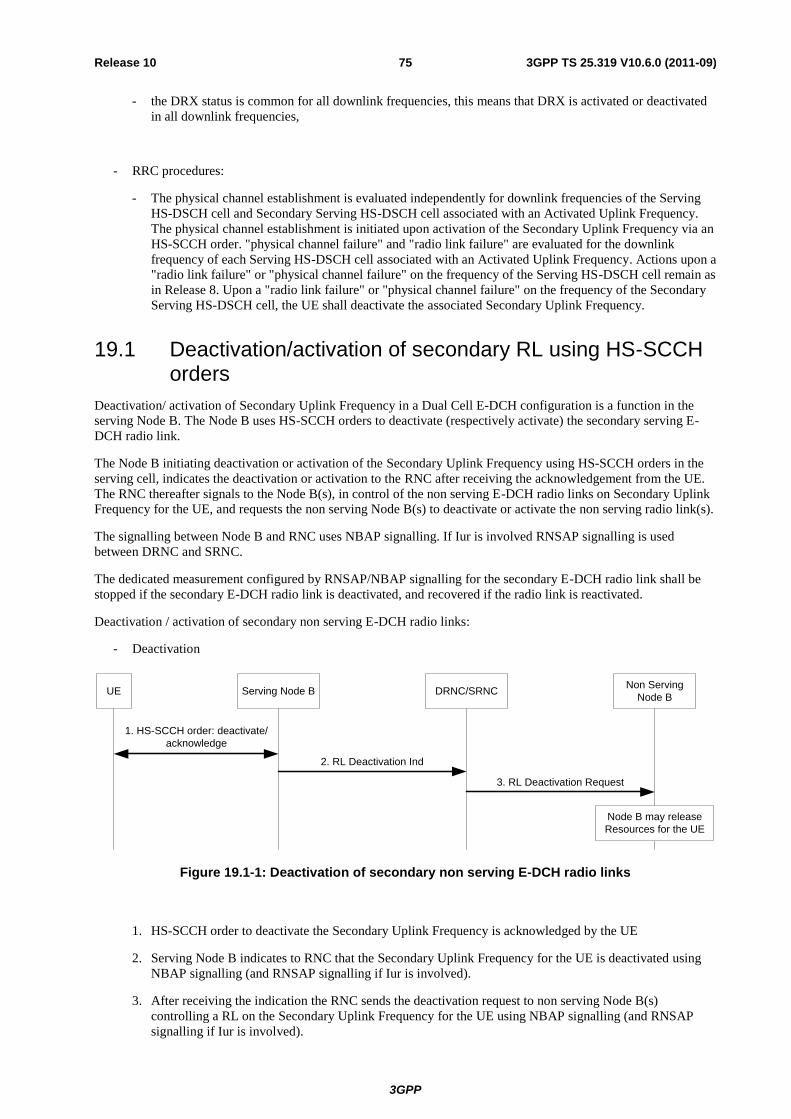
3GPP
3GPP TS 25.319 V10.6.0 (2011-09) 75 Release 10
- the DRX status is common for all downlink frequencies, this means that DRX is activated or deactivated
in all downlink frequencies,
- RRC procedures:
- The physical channel establishment is evaluated independently for downlink frequencies of the Serving
HS-DSCH cell and Secondary Serving HS-DSCH cell associated with an Activated Uplink Frequency.
The physical channel establishment is initiated upon activation of the Secondary Uplink Frequency via an
HS-SCCH order. "physical channel failure" and "radio link failure" are evaluated for the downlink
frequency of each Serving HS-DSCH cell associated with an Activated Uplink Frequency. Actions upon a
"radio link failure" or "physical channel failure" on the frequency of the Serving HS-DSCH cell remain as
in Release 8. Upon a "radio link failure" or "physical channel failure" on the frequency of the Secondary
Serving HS-DSCH cell, the UE shall deactivate the associated Secondary Uplink Frequency.
19.1 Deactivation/activation of secondary RL using HS-SCCH orders
Deactivation/ activation of Secondary Uplink Frequency in a Dual Cell E-DCH configuration is a function in the
serving Node B. The Node B uses HS-SCCH orders to deactivate (respectively activate) the secondary serving E-
DCH radio link.
The Node B initiating deactivation or activation of the Secondary Uplink Frequency using HS-SCCH orders in the
serving cell, indicates the deactivation or activation to the RNC after receiving the acknowledgement from the UE.
The RNC thereafter signals to the Node B(s), in control of the non serving E-DCH radio links on Secondary Uplink
Frequency for the UE, and requests the non serving Node B(s) to deactivate or activate the non serving radio link(s).
The signalling between Node B and RNC uses NBAP signalling. If Iur is involved RNSAP signalling is used
between DRNC and SRNC.
The dedicated measurement configured by RNSAP/NBAP signalling for the secondary E-DCH radio link shall be
stopped if the secondary E-DCH radio link is deactivated, and recovered if the radio link is reactivated.
Deactivation / activation of secondary non serving E-DCH radio links:
- Deactivation
UE Serving Node B DRNC/SRNCNon Serving
Node B
1. HS-SCCH order: deactivate/
acknowledge
2. RL Deactivation Ind
3. RL Deactivation Request
Node B may release
Resources for the UE
Figure 19.1-1: Deactivation of secondary non serving E-DCH radio links
1. HS-SCCH order to deactivate the Secondary Uplink Frequency is acknowledged by the UE
2. Serving Node B indicates to RNC that the Secondary Uplink Frequency for the UE is deactivated using
NBAP signalling (and RNSAP signalling if Iur is involved).
3. After receiving the indication the RNC sends the deactivation request to non serving Node B(s)
controlling a RL on the Secondary Uplink Frequency for the UE using NBAP signalling (and RNSAP
signalling if Iur is involved).
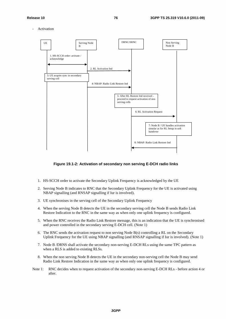
3GPP
3GPP TS 25.319 V10.6.0 (2011-09) 76 Release 10
- Activation
1. HS-SCCH order: activate /
acknowledge
2. RL Activation Ind
5: After RL Restore Ind received -
proceed to request activation of non
serving cells
4: NBAP: Radio Link Restore Ind
6: RL Activation Request
UE Serving Node
B
DRNC/SRNC Non Serving
Node B
8: NBAP: Radio Link Restore Ind
7: Node B / UE handles activation
simular as for RL Setup in soft
handover
3: UE acquire sync in secondary
serving cell
Figure 19.1-2: Activation of secondary non serving E-DCH radio links
1. HS-SCCH order to activate the Secondary Uplink Frequency is acknowledged by the UE
2. Serving Node B indicates to RNC that the Secondary Uplink Frequency for the UE is activated using
NBAP signalling (and RNSAP signalling if Iur is involved).
3. UE synchronises in the serving cell of the Secondary Uplink Frequency
4. When the serving Node B detects the UE in the secondary serving cell the Node B sends Radio Link
Restore Indication to the RNC in the same way as when only one uplink frequency is configured.
5. When the RNC receives the Radio Link Restore message, this is an indication that the UE is synchronised
and power controlled in the secondary serving E-DCH cell. (Note 1)
6. The RNC sends the activation request to non serving Node B(s) controlling a RL on the Secondary
Uplink Frequency for the UE using NBAP signalling (and RNSAP signalling if Iur is involved). (Note 1)
7. Node B /DRNS shall activate the secondary non-serving E-DCH RLs using the same TPC pattern as
when a RLS is added to existing RLSs.
8. When the non serving Node B detects the UE in the secondary non-serving cell the Node B may send
Radio Link Restore Indication in the same way as when only one uplink frequency is configured.
Note 1: RNC decides when to request activation of the secondary non-serving E-DCH RLs - before action 4 or
after.

3GPP
3GPP TS 25.319 V10.6.0 (2011-09) 77 Release 10
20 Multi-Carrier E-DCH operation (1.28 Mcps TDD only)
For 1.28 Mcps TDD, and in CELL_DCH state, certain categories of UEs may be configured into the Multi-Carrier
E-DCH operation. In Multi-Carrier E-DCH operation, a UE can be configured in Single-Carrier HSDPA or Multi-
Carrier HSDPA operation on a single frequency band. Therefore, a UE is configured with single or multiple
downlink frequencies and multiple uplink frequencies, and the transmission is characterized as simultaneous
transmission E-DCH transport channels.
Multi-Carrier E-DCH operation is characterized by the following properties:
- Physical channel structure:
- In MC-HSUPA, the UE transmission power should be shared among all the uplink carriers.
- In MC-HSUPA, there is only one CCTrCH of E-DCH type per uplink carrier per UE, there is only one E-
DCH per CCTrCH, and there is only one transport block per TTI per E-DCH per uplink carrier.
- E-PUCH and its corresponding control channels such as E-AGCH and E-HICH shall be configured on the
same carrier.
- The coding schemes of E-DCH, E-UCCH, E-AGCH and E-HICH are unchanged. The coding of E-DCH,
E-UCCH, E-AGCH and E-HICH on each uplink carrier should be independent. E-UCCH on one uplink
carrier is multiplexed onto the E-PUCH on the same carrier.
- There is no interleaving among all the uplink carriers for E-DCH, E-UCCH, E-AGCH and E-HICH.
- The spreading, burst format, timeslot format, and timing of E-AGCH/E-PUCH/E-HICH remain
unchanged
- All uplink carriers of one UE use the same TA
- The inner loop power control of E-PUCH shall be independent for each uplink carrier of one UE
- When MC-HSUPA and uplink SPS are configured simultaneously, E-AGCH type 2 is used to schedule
E-PUCH on the carrier where uplink SPS is configured while E-AGCH type 1 is used to schedule E-
PUCH on the carriers where uplink SPS is not configured.
- Only one carrier is configured to UE for the E-RUCCH procedure of UE. When UE is triggered to send
the SI on E-RUCCH, UE only initiates the E-RUCCH procedure on the configured uplink carrier.
- The definition of UPH in MC-HSUPA is the same as single carrier HSUPA. Pmax is determined by the
power class of the UE. The UPH of one E-PUCH carrier can be derived from the UPH of another E-
PUCH carrier.
- SNPL is reported per carrier group. UE shall divide all the uplink E-DCH carriers into several carrier
groups according to the higher layer configuration. The carriers in the same carrier group have the same
SNPL value.
- Control channel DRX should be supported in MC-HSUPA. The E-AGCH reception pattern is the same
for all the carriers of the UE. For multi-carrier E-DCH transmission and multi-carrier HS-DSCH
reception, the activation and deactivation of the discontinuous downlink reception operation applies to
HS-SCCH and E-AGCH on all carriers, namely, when receiving a DRX activation order on HS-SCCH,
the UE shall activate the DRX of HS-SCCH and E-AGCH on all carriers; when receiving a DRX
deactivation order on HS-SCCH, the UE shall deactivate the DRX of HS-SCCH and E-AGCH on all
carriers.
- No physical layer signaling (e.g. HS-SCCH orders) for activation and deactivation of UL carriers is
introduced.
- For MC-HSUPA, the primitive reporting of in-sync and out-of-sync is on per-UE basis for both uplink
and downlink
- Downlink synchronization primitives

3GPP
3GPP TS 25.319 V10.6.0 (2011-09) 78 Release 10
- in-sync shall be reported if at least one downlink physical channel on all carriers is received with a
correct CRC in the current sub frame
- Out-of-sync shall be reported if no downlink physical channel on all carriers has been received with a
correct CRC in the out-of-sync detection window period
- When DPCH is configured in MC-HSUPA, UE shall measure the burst reception quality and the CRC
of DPCH for DL sync detection. Otherwise, the UE shall measure the CRC of all the HS-SCCH, E-
AGCH, and HS-PDSCH for sync detection.
- For MC-HSUPA, radio link monitoring procedures for both uplink and downlink remain unchanged
- MAC architecture:
- Only MAC-i/is entity is supported,
- In the UE side, the MAC-i/is has a multiplexing entity and TSN setting entity common to all E-DCH
transport channels; however, there is a HARQ sub-entity per E-DCH transport channel and one E-DCH
per uplnk carrier (see Figure 7.2.6-3a). In the UTRAN side, the MAC-i has a HARQ sub-entity per E-
DCH transport channel and a de-multiplexing entity for all E-DCH transport channels. The de-
multiplexing entity demultiplexes MAC-i PDUs and forwards the received MAC-is PDUs to the
associated MAC-d flows (see Figure 7.3.8-2a),
- The Reordering Queue Distribution entity in the MAC-is receives all the MAC-d flows from the serving
E-DCH cell (see Figure 7.3.7-3a),
- Each HARQ sub-entity is composed of multiple HARQ processes,
- For uplink transmissions, the length of the TSN field in the MAC-is header shall be 6 or 14 bits according
to the higher layer configuration,
- At every TTI, the MAC-i/is will select the RLC PDU size for every carrier independenly,
- DCH is supported in MC-HSUPA and can be only configured on one uplink carrier,
- Non-scheduled transmission is not supported in MC-HSUPA,
- Scheduling procedures:
- Scheduled transmissions can be sent on any uplink carrier. The resources to be used on each uplink
carrier are signalled via Absolute Grants,
- for one UE, there is only one E-RNTI for all uplink carriers,
- absolute grant is provided specifically to each uplink carrier,
- The extended SI structure is introduced for MC HSUPA to report TEBS, HLID, HLBS, UPH of one
carrier and the SNPLs of one or more carrier groups to NodeB.
- T_SI is maintained per UE and the SI reporting scheme for MC HSUPA is same as that for single carrier
HSUPA.
- Mobility and measurements:
- The reference frequency is introduced for defining intra-frequency cell and inter-frequecy cell,
- The mobility procedure for MC-HSUPA should be identical to the legacy mobility procedure based on the
reference frequency,
- RRC procedures:
- The criteria for evaluating "physical channel failure" and "radio link failure" keep as Release 9 and
actions upon a "radio link failure" or "physical channel failure" also remain as in Release 9.

3GPP
3GPP TS 25.319 V10.6.0 (2011-09) 79 Release 10
21 MU-MIMO operation in HSUPA channel in 1.28Mcps TDD
In 1.28Mcps TDD, MU-MIMO operation in HSUPA channel includes the following contents.
- Four midamble allocation patterns (pattern 1A, pattern 1B, pattern 2A, pattern 2B) for the special default
midamble allocation scheme as in [13] shall be used for MU-MIMO operation. For the UEs sharing the same
uplink physical resource in the same TTI, the different midamble allocation patterns shall be allocated to
them.
- A MU-MIMO capable UE can be signalled to operate in "MU-MIMO mode" by RRC.
- MU-MIMO can be applied in CELL_DCH and CELL_FACH.
- If UE is configured in MU-MIMO mode and the default midamble allocation scheme is signalled to UE by
RRC, the default or special default midamble allocation scheme can be used. Whether the default or special
default midamble allocation scheme is used is signalled to UE dynamically through E-AGCH in [15].
- When UE is configured in MU-MIMO mode, the NodeB scheduler uses E-AGCH type 2 to signal the E-
DCH related information to UE. When the special default midamble allocation scheme is signalled to UE
through E-AGCH, the special default midamble pattern indicator on E-AGCH signals the UE’s midamble
allocation pattern.
- When the special default midamble allocation scheme is signalled to UE through E-AGCH, the signature
sequence allocated to UE to indicate the ACK/NACK for E-PUCH is related to both the E-DCH resources
allocated by NodeB and the special default midamble pattern indicator signalled on E-AGCH.
- In CELL_DCH and CELL_FACH, the Node B scheduler decides whether to allocate the same uplink
physical resource to multiple UEs in the same TTI based on the spatial isolation between the wireless
channels of these UEs.
- In CELL_DCH, standalone midamble channel can be used to improve the uplink channel estimation, thus
improving the wireless channel spatial isolaton decision performance.

3GPP
3GPP TS 25.319 V10.6.0 (2011-09) 80 Release 10
Annex A (informative): Change history
Change history
Date TSG # TSG Doc. CR Rev Subject/Comment Old New
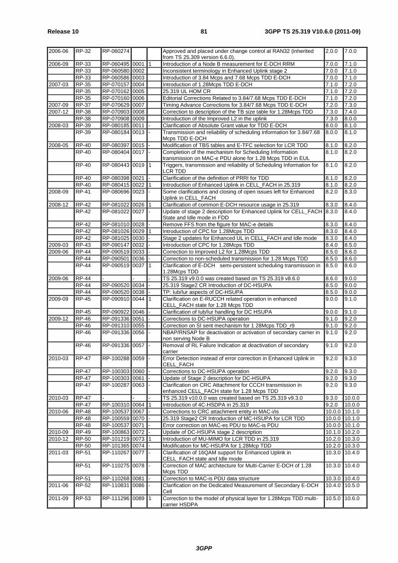
3GPP
3GPP TS 25.319 V10.6.0 (2011-09) 81 Release 10
2006-06 RP-32 RP-060274 Approved and placed under change control at RAN32 (inherited from TS 25.309 version 6.6.0).
2.0.0 7.0.0
2006-09 RP-33 RP-060495 0001 1 Introduction of a Node B measurement for E-DCH RRM 7.0.0 7.1.0
RP-33 RP-060580 0002 Inconsistent terminology in Enhanced Uplink stage 2 7.0.0 7.1.0
RP-33 RP-060586 0003 Introduction of 3.84 Mcps and 7.68 Mcps TDD E-DCH 7.0.0 7.1.0
2007-03 RP-35 RP-070157 0004 Introduction of 1.28Mcps TDD E-DCH 7.1.0 7.2.0
RP-35 RP-070162 0005 25.319 UL HOM CR 7.1.0 7.2.0
RP-35 RP-070160 0006 Editorial Corrections Related to 3.84/7.68 Mcps TDD E-DCH 7.1.0 7.2.0
2007-09 RP-37 RP-070629 0007 Timing Advance Corrections for 3.84/7.68 Mcps TDD E-DCH 7.2.0 7.3.0
2007-12 RP-38 RP-070903 0008 Correction to description of the TB size table for 1.28Mcps TDD 7.3.0 7.4.0
RP-38 RP-070908 0009 Introduction of the Improved L2 in the uplink 7.3.0 8.0.0
2008-03 RP-39 RP-080185 0011 - Clarification of Absolute Grant value for TDD E-DCH 8.0.0 8.1.0
RP-39 RP-080184 0013 - Transmission and reliability of scheduling information for 3.84/7.68 Mcps TDD E-DCH
8.0.0 8.1.0
2008-05 RP-40 RP-080397 0015 - Modification of TBS tables and E-TFC selection for LCR TDD 8.1.0 8.2.0
RP-40 RP-080404 0017 - Completion of the mechanism for Scheduling Information transmission on MAC-e PDU alone for 1.28 Mcps TDD in EUL
8.1.0 8.2.0
RP-40 RP-080443 0019 1 Triggers, transmission and reliability of Scheduling Information for LCR TDD
8.1.0 8.2.0
RP-40 RP-080398 0021 - Clarification of the definition of PRRI for TDD 8.1.0 8.2.0
RP-40 RP-080415 0022 1 Introduction of Enhanced Uplink in CELL_FACH in 25.319 8.1.0 8.2.0
2008-09 RP-41 RP-080696 0023 - Some clarifications and closing of open issues left for Enhanced Uplink in CELL_FACH
8.2.0 8.3.0
2008-12 RP-42 RP-081022 0026 1 Clarification of common E-DCH resource usage in 25.319 8.3.0 8.4.0
RP-42 RP-081022 0027 - Update of stage 2 description for Enhanced Uplink for CELL_FACH State and Idle mode in FDD
8.3.0 8.4.0
RP-42 RP-081010 0028 - Remove FFS from the figure for MAC-e details 8.3.0 8.4.0
RP-42 RP-081026 0029 1 Introduction of CPC for 1.28Mcps TDD 8.3.0 8.4.0
RP-42 RP-081025 0030 - Stage 2 updates for Enhanced UL in CELL_FACH and Idle mode 8.3.0 8.4.0
2009-03 RP-43 RP-090147 0032 - Introduction of CPC for 1.28Mcps TDD 8.4.0 8.5.0
2009-06 RP-44 RP-090519 0033 - Correction to Improved L2 for 1.28Mcps TDD 8.5.0 8.6.0
RP-44 RP-090501 0036 - Correction to non-scheduled transmission for 1.28 Mcps TDD 8.5.0 8.6.0
RP-44 RP-090519 0037 1 Clarification of E-DCH semi-persistent scheduling transmission in 1.28Mcps TDD
8.5.0 8.6.0
2009-06 RP-44 - - - TS 25.319 v9.0.0 was created based on TS 25.319 v8.6.0 8.6.0 9.0.0
RP-44 RP-090520 0034 - 25.319 Stage2 CR Introduction of DC-HSUPA 8.5.0 9.0.0
RP-44 RP-090520 0038 - TP: Iub/Iur aspects of DC-HSUPA 8.5.0 9.0.0
2009-09 RP-45 RP-090910 0044 1 Clarification on E-RUCCH related operation in enhanced CELL_FACH state for 1.28 Mcps TDD
9.0.0 9.1.0
RP-45 RP-090922 0046 - Clarification of Iub/Iur handling for DC HSUPA 9.0.0 9.1.0
2009-12 RP-46 RP-091336 0051 - Corrections to DC-HSUPA operation 9.1.0 9.2.0
RP-46 RP-091310 0055 - Correction on SI sent mechanism for 1 28Mcps TDD_r9 9.1.0 9.2.0
RP-46 RP-091336 0056 - NBAP/RNSAP for deactivation or activation of secondary carrier in non serving Node B
9.1.0 9.2.0
RP-46 RP-091336 0057 - Removal of RL Failure Indication at deactivation of secondary carrier
9.1.0 9.2.0
2010-03 RP-47 RP-100288 0059 - Error Detection instead of error correction in Enhanced Uplink in CELL_FACH
9.2.0 9.3.0
RP-47 RP-100303 0060 - Corrections to DC-HSUPA operation 9.2.0 9.3.0
RP-47 RP-100303 0061 - Update of Stage 2 description for DC-HSUPA 9.2.0 9.3.0
RP-47 RP-100287 0063 - Clarification on CRC Attachment for CCCH transmission in enhanced CELL_FACH state for 1.28 Mcps TDD
9.2.0 9.3.0
2010-03 RP-47 - - - TS 25.319 v10.0.0 was created based on TS 25.319 v9.3.0 9.3.0 10.0.0
RP-47 RP-100310 0064 1 Introduction of 4C-HSDPA in 25.319 9.2.0 10.0.0
2010-06 RP-48 RP-100537 0067 - Corrections to CRC attachment entity in MAC-i/is 10.0.0 10.1.0
RP-48 RP-100559 0070 - 25.319 Stage2 CR Introduction of MC-HSUPA for LCR TDD 10.0.0 10.1.0
RP-48 RP-100537 0071 - Error correction on MAC-es PDU to MAC-is PDU 10.0.0 10.1.0
2010-09 RP-49 RP-100863 0072 - Update of DC-HSUPA stage 2 description 10.1.0 10.2.0
2010-12 RP-50 RP-101219 0073 1 Introduction of MU-MIMO for LCR TDD in 25.319 10.2.0 10.3.0
RP-50 RP-101365 0074 - Modification for MC-HSUPA for 1.28Mcp TDD 10.2.0 10.3.0
2011-03 RP-51 RP-110267 0077 - Clarification of 16QAM support for Enhanced Uplink in CELL_FACH state and Idle mode
10.3.0 10.4.0
RP-51 RP-110275 0078 - Correction of MAC architecture for Multi-Carrier E-DCH of 1.28 Mcps TDD
10.3.0 10.4.0
RP-51 RP-110268 0081 - Correction to MAC-is PDU data structure 10.3.0 10.4.0
2011-06 RP-52 RP-110831 0086 - Clarification on the Dedicated Measurement of Secondary E-DCH Cell
10.4.0 10.5.0
2011-09 RP-53 RP-111296 0089 1 Correction to the model of physical layer for 1.28Mcps TDD multi-carrier HSDPA
10.5.0 10.6.0