3GPP TR 25.889 V1.2
30
3GPP TR 25.889 V1.2.1 (2002-11) Technical Report 3rd Generation Partnership Project; Technical Specification Group Radio Access Network; Feasibility Study considering the viable deployment of UTRA in additional and diverse spectrum arrangements (Release 6) The present document has been developed within the 3 rd Generation Partnership Project (3GPP TM ) and may be further elaborated for the purposes of 3GPP. The present document has not been subject to any approval process by the 3GPP Organizational Partners and shall not be implemented. This Specification is provided for future development work within 3GPP only. The Organizational Partners accept no liability for any use of this Specification. Specifications and reports for implementation of the 3GPP TM system should be obtained via the 3GPP Organizational Partners' Publications Offices.
Transcript of 3GPP TR 25.889 V1.2
3GPP TR 25.889 V1.2.1 (2002-11)Technical Report
3rd Generation Partnership Project;Technical Specification Group Radio Access Network;
Feasibility Study considering the viable deployment of UTRAin additional and diverse spectrum arrangements
(Release 6)
The present document has been developed within the 3rd Generation Partnership Project (3GPP TM) and may be further elaborated for the purposes of 3GPP.
The present document has not been subject to any approval process by the 3GPP Organizational Partners and shall not be implemented.This Specification is provided for future development work within 3GPP only. The Organizational Partners accept no liability for any use of this Specification.Specifications and reports for implementation of the 3GPP TM system should be obtained via the 3GPP Organizational Partners' Publications Offices.
3GPP
3GPP TR 25.889 V1.2.1 (2002-11)2Release 6
Select keywords from list provided in specs database.
Keywords<keyword[, keyword]>
3GPP
Postal address
3GPP support office address650 Route des Lucioles - Sophia Antipolis
Valbonne - FRANCETel.: +33 4 92 94 42 00 Fax: +33 4 93 65 47 16
Internethttp://www.3gpp.org
Copyright Notification
No part may be reproduced except as authorized by written permission.The copyright and the foregoing restriction extend to reproduction in all media.
© 2002, 3GPP Organizational Partners (ARIB, CWTS, ETSI, T1, TTA, TTC).All rights reserved.

3GPP
3GPP TR 25.889 V1.2.1 (2002-11)3Release 6
Contents
Foreword...........................................................................................................................................................56
Introduction ......................................................................................................................................................56
1 Scope ......................................................................................................................................................67
2 References ..............................................................................................................................................67
3 Definitions, symbols and abbreviations .................................................................................................783.1 Definitions..............................................................................................................................................................783.2 Symbols .................................................................................................................................................................783.3 Abbreviations.........................................................................................................................................................78
4 Background and Introduction.................................................................................................................784.1 Scope and Objective of work .................................................................................................................................894.1.1 General considerations .....................................................................................................................................894.1.2 UTRA FDD......................................................................................................................................................894.1.3 UTRA TDD....................................................................................................................................................9104.1.4 Caveat/Notice .................................................................................................................................................910
5 Description of the spectrum arrangements ...........................................................................................910
6 Enabling technologies for operation of UTRA FDD in the new bands .............................................10116.1 Solutions for implementing variable duplex separation in one terminal............................................................10116.1.1 Status in 3GPP specifications for accommodating variable duplex separation in one terminal ...................10116.1.1.1 Signalling and control of the UE (RAN2) ....................................................................................................10116.1.1.1.1 Common channel aspects........................................................................................................................10116.1.1.1.2 Dedicated channel aspects ....................................................................................................................11126.1.1.1.3 UE capability aspects..............................................................................................................................11126.1.1.1.4 Signalling summary ..............................................................................................................................12136.1.1.2 Frequency bands and hardware issues (RAN4)............................................................................................12136.1.1.2.1 Frequency bands .....................................................................................................................................12136.1.1.2.2 RF performance ......................................................................................................................................12136.1.2 Examples of Implementation of variable duplex separation in one terminal................................................12146.1.3 VDT Conclusion ..........................................................................................................................................14156.2 Solutions for having a terminal accommodating frequency band asymmetry ...................................................1415
7 Examples for viable implementations of spectrum arrangements for UTRA FDD ...........................14157.1 DL usage of the new band 2500 – 2690 MHz in conjunction with the Band I for UTRA FDD........................14167.1.1 Radio Network Performance Aspects regarding utilization of the 2500 – 2690 MHz Band........................15177.1.1.1 Relevant Propagation Aspects for 2.5 GHz Band ........................................................................................15177.1.1.2 Impact of increased PL in the 2.5 GHz band on UTRA UL/DL Cell Coverage...........................................15177.1.2 Radio Resource Management (RRM) aspects with extension DL carriers in 2500 – 2690 MHz ................16187.1.2.1 UL interference scenario ..............................................................................................................................16187.1.2.2 Interference detection and avoidance ...........................................................................................................16187.1.3 Towards an UTRA Standard for supporting DL optimised utilisation of the 2500 – 2690 MHz band ........18207.1.3.1 Overall Objectives for UTRA 3GPP standards development to support DL optimised utilisation of the
2500 – 2690 MHz band.....................................................................................................................19217.1.3.2 Towards a technical framework for extending UTRA to support DL optimised utilisation of the 2500 –
2690 MHz band.................................................................................................................................19217.1.4 Needed Additions to the UTRA Standard for supporting DL optimised utilisation of the 2500 – 2690
MHz band ...............................................................................................................................................21237.1.5 Summary of section 7.1 for usage of the new band in 2500 – 2690 MHz in conjunction with the Band I
for UTRA................................................................................................................................................21237.2 Use of VDT for deployment of public indoor systems ......................................................................................22247.2.1 Introduction to the scenario ..........................................................................................................................22247.2.2 Assumptions for the scenario .......................................................................................................................22247.2.3 UL interference from increased traffic in indoor system..............................................................................23257.2.4 Controlling the UL interference with the use of VDT..................................................................................24267.2.5 Summary of the use of VDT for deployment for public indoor systems......................................................2628

3GPP
3GPP TR 25.889 V1.2.1 (2002-11)4Release 6
7.2.6 Handover between cells with different duplex spacing ................................................................................26287.3 UL/DL usage of the new band in 2500 – 2690 MHz in conjunction with the Band I for UTRA FDD .............26287.4 UL/DL plus additional DL usage of the new band in 2500 – 2690 MHz in conjunction with the Band I for
UTRA FDD..................................................................................................................................................2628
8 The use of UTRA TDD in the 2500-2690MHz band.........................................................................2628
9 Recommendations ..............................................................................................................................2729
10 Open issues.........................................................................................................................................2729
11 Conclusion..........................................................................................................................................2729
Annex <A>: Impact of increased PL in the 2.5 GHz band on UTRA FDD UL/DL Cell Coverage ....2830
Annex <X>: Change history ......................................................................................................................3032
3GPP
3GPP TR 25.889 V1.2.1 (2002-11)5Release 6
ForewordThis Technical Report has been produced by the 3rd Generation Partnership Project (3GPP).
The contents of the present document are subject to continuing work within the TSG and may change following formalTSG approval. Should the TSG modify the contents of the present document, it will be re-released by the TSG with anidentifying change of release date and an increase in version number as follows:
Version x.y.z
where:
x the first digit:
1 presented to TSG for information;
2 presented to TSG for approval;
3 or greater indicates TSG approved document under change control.
y the second digit is incremented for all changes of substance, i.e. technical enhancements, corrections,updates, etc.
z the third digit is incremented when editorial only changes have been incorporated in the document.
IntroductionThis clause is optional. If it exists, it is always the second unnumbered clause.

3GPP
3GPP TR 25.889 V1.2.1 (2002-11)6Release 6
1 ScopeThe present document summarises results from the Study Item “Feasibility Study considering the viable deployment ofUTRA in additional and diverse spectrum arrangements”. Both UTRA FDD and UTRA TDD are considered. ForUTRA FDD, the spectrum arrangements include the present FDD frequency bands as defined in Release 5 of therelevant 3GPP specifications as well as the additional bands identified for IMT-2000 by ITU-R WRC-2000, inparticular the band 2500-2690 MHz. For UTRA TDD, the study focuses on the use of the additional band 2500-2690MHz.
2 ReferencesThe following documents contain provisions which, through reference in this text, constitute provisions of the presentdocument.
• References are either specific (identified by date of publication, edition number, version number, etc.) ornon-specific.
• For a specific reference, subsequent revisions do not apply.
• For a non-specific reference, the latest version applies. In the case of a reference to a 3GPP document (includinga GSM document), a non-specific reference implicitly refers to the latest version of that document in the sameRelease as the present document.
[<seq>] <doctype> <#>[ ([up to and including]{yyyy[-mm]|V<a[.b[.c]]>}[onwards])]: "<Title>".
[1] 3GPP TR 41.001: "GSM Release specifications".
[2] 3GPP TR 21 912 (V3.1.0): "Example 2, using fixed text".
[3] ITU-R 8F/623, “REPORT OF THE SEVENTH MEETING OF WORKING PARTY 8F(Queenstown, 27 February – 5 March 2002)”; ATTACHMENT 7.2, “Working document onpreferred options for frequency arrangements for IMT-2000 systems in bands identified byWARC-92 and WRC-2000 (Revision to Att. 8.2 of Doc. 8F/489)”
[4] 3GPP TS 25.331 v 3.9.0 (2001-12)“Radio Resource Control (RRC); Protocol Specification(Release 1999)”
[5] R2-011087 Proposed CR 776 on Missing UARFCN uplink info, Nokia.
[6] R2-011511 Approved Report of the 21st TSG-RAN WG2 meeting, Secretary.
[7] 3GPP TS 25.101 v 3.9.0 (2001-12) “UE Radio Transmission and Reception (FDD)(Release 1999)”
[8] 3GPP TS 25.104 v 3.9.0 (2001-12) “UTRA (BS) FDD; Radio transmission and Reception(Release 1999)”
[9] 3GPP TR 25.931 V3.6.0 (2002-03), “3rd Generation Partnership Project; Technical SpecificationGroup RAN; UTRAN Functions, Examples on Signalling Procedures (Release 1999).
[10] UMTS Forum Report #9: “The UMTS Third Generation Market – Structuring the ServiceRevenues Opportunities”
[11] UMTS Forum Report #13: “The UMTS Third Generation Market – Phase II, Structuring theService Revenues Opportunities”
[12] SAG 34/4, 12-14 Sept 2001
[13] SAG 35/2, 3-5 Dec 2001
[14] UMTS Forum SAG Doc SAG 36/3, 11-12 April 2002
3GPP
3GPP TR 25.889 V1.2.1 (2002-11)7Release 6
[15] Holma, Toskala, ”WCDMA for UMTS”, Wiley
[16] Wacker, Laiho, Novosad, “Radio Network Planning and Optimisation for UMTS”, Wiley
3 Definitions, symbols and abbreviationsDelete from the above heading those words which are not applicable.
Subclause numbering depends on applicability and should be renumbered accordingly.
3.1 DefinitionsFor the purposes of the present document, the [following] terms and definitions [given in ... and the following] apply.
Definition format
<defined term>: <definition>.
example: text used to clarify abstract rules by applying them literally.
3.2 SymbolsFor the purposes of the present document, the following symbols apply:
Symbol format
<symbol> <Explanation>
3.3 AbbreviationsFor the purposes of the present document, the following abbreviations apply:
Abbreviation format
<ACRONYM> <Explanation>
4 Background and IntroductionThe present 3GPP specifications cover the IMT-2000 2 GHz band (Band I and II), in accordance with ITU-R RadioRegulations Article S5 Footnote S5.388, in R99 and Rel4 and the work is continuing with the UMTS1900 Band IIimprovements and UMTS 1800 Band III.
ITU-R WRC-2000 identified additional extension bands for IMT-2000 that requires further studies for the subsequentfuture deployment of UTRA in the whole or parts of the bands as indicated below:
- 806 - 960 MHz (The whole band 806 - 960 MHz is not identified on a global basis for IMT-2000 due tovariation in the primary Mobile Service allocation across the three ITU Regions)
- 1710 - 1885 MHz, where the work is progressing under UMTS1800 WI.
- 2500 - 2690 MHz (In ITU Region 1 the bands 2500 - 2520 MHz and 2670 - 2690 MHz is also allocated on a co-primary basis to the Mobile Satellite Service subject to market demand)
3GPP
3GPP TR 25.889 V1.2.1 (2002-11)8Release 6
4.1 Scope and Objective of work
4.1.1 General considerations
The viable deployment of both UTRA modes FDD and TDD in additional and diverse spectrum arrangements should beassessed. Due to the difference in their duplex scheme, these modes have unequal intrinsic characteristics. It seemstherefore appropriate to treat both UTRA modes separately from each other.
For the purpose of this feasibility study, it is assumed that additional spectrum, and in particular the frequency band2500-2690 MHz, will be used exclusively by either UTRA FDD or UTRA TDD, respectively. Thus, co-existencebetween UTRA FDD and UTRA TDD is not considered, and corresponding compatibility studies between these modesare not considered in this report. It is however acknowledged that the combination of FDD and TDD in new bands is avalid option, as already discussed in ITU-R WP 8F.
4.1.2 UTRA FDD
In case of UTRA FDD, the assessment includes
- Duplex spacing arrangements other than for Bands I, II and III.
- Arbitrary selectable or variable duplex spacing methods.
- Use of asymmetric spectrum arrangements considering the need for additional downlink traffic capacity
- Impacts on equipment performance requirements due to new frequency bands and operating bandwidths.
- Terminal capabilities and signalling
- Possible interface impacts
Spectrum bands to study in an initial phase are
Present bands:
- 1920 - 1980 MHz paired with 2110 – 2170 MHz Band I (core band)
- 1850 - 1910 MHz paired with 1930 – 1990 MHz Band II (PCS1900 band)
- 1710 - 1785 MHz paired with 1805 – 1880 MHz Band III (GSM1800 band)
Implementations to study for new bands and combinations of bands:
1) 1710 - 1770 MHz paired with 2110 - 2170 MHz
2a) 1710 - 1800 MHz paired with 2110 - 2200 MHz
2b)1920 - 2010 MHz paired with 2110 - 2200 MHz
3) 1755 - [1805] MHz paired with 2110 - [2160] MHz
4) 1710 - [1755] MHz paired with 1805 – [1850] MHz
5) 2500 - 2690 MHz:
(Alt A) Entire band as additional DL to other bands used for technologies within scope & objective of 3GPP.
(Alt B) DL and UL in this band.
(Alt C) DL and UL in this band, and additional DL to other bands used for technologies within scope &objective of 3GPP.
The technology study should describe a possible technical implementation of a Variable Duplex technology(VDT)solution to satisfy the addressed new spectrum arrangements but also considering the existing spectrumarrangements. Enabling technologies for operating of UTRA FDD in the new bands are examined in clause 6. Examplesfor viable implementations of spectrum arrangements for UTRA FDD are described in clause 7.

3GPP
3GPP TR 25.889 V1.2.1 (2002-11)9Release 6
4.1.3 UTRA TDD
In case of UTRA TDD, the same frequency channel is used sequentially for transmission in the uplink and downlinkdirection. Therefore, the duplex arrangement is independent of the spectrum arrangement. Other technical issues andassessments to consider are:
- Impacts on equipment performance requirements due to new frequency bands and operating bandwidths.
- Terminal capabilities and signalling.
- Possible interface impacts.
4.1.4 Caveat/Notice
The information in this TR is partly based on text from RAN4 meeting documents that also contained information inareas outside of the RAN4 mandate. Examples are paragraphs containing information on how the split of uplink versusdownlink traffic will develop with time, as well as suggestions on how to develop a specification assuming certaindecisions are taken in e.g. regulatory bodies on how the new spectrum is to be used. As this information is useful inhelping understanding of the technical feasibility assessment and related conclusions in these sections, this informationhas been kept. RAN4 has refrained from discussing the text parts outside of its mandate for this TR, and thusconclusions should not be drawn from these parts.
The part related to the technical feasibility, and especially the text in the conclusion clause, have been agreed by RANWG4.
5 Description of the spectrum arrangementsDocument 8F/623 [3] lists several options for paired and unpaired frequency arrangements for IMT-2000 systems inbands identified by WARC-92 and WRC-2000.
For UTRA FDD, the options for paired frequency arrangements are applicable. Table 1 provides a selection of theseoptions and additionally proposes some further opportunities based on VDT.
Table 1: FDD Frequency Arrangements
Arrangements UE Tx (MHz) Duplex CentreGap (MHz)
BS Tx (MHz) Duplexseparation
(MHz)
Remarks
Band I 1920 - 1980 130 2110 - 2170 190 Option 1 in 6.1.2 and [3]Band II 1850 – 1910 20 1930 - 1990 80 Option 3 in 6.1.2 and [3]Band III 1710 - 1785 20 1805 - 1880 95 Option 2 in 6.1.2 and [3]
(*) 1710 – 1755 50 1805 - 1850 95(*) 1755 – 1805 305 2110 - 2160 355 Option 4 in 6.1.2 and [3](*) 1710 - 1770 240 2110 - 2170 400 Option 5 in 6.1.2 and [3](*) 1920 - 1980 520 2500 - 2690 Variable(*) 1850 – 1910 590 2500 - 2690 Variable(*) 1710 - 1785 715 2500 - 2690 Variable(*) 1710 -1770 730 2500 - 2690 Variable(**) 2500 (2520) - x y≥20 z – (2670) 2690 Variable x, y and z to be defined(**) z – (2670) 2690 y≥20 2500 (2520) - x Variable x, y and z to be defined.
(Reversed duplexdirection)
Note 1: Combination of Bands (*) and Bands (**) may be required to be considered in the future work.
Note 2: ITU-R Resolution 225 from the World Radio Communication Conference 2000 (WRC-2000) states thatthe bands 2500 - 2520 MHz and 2670 - 2690 MHz (as identified for IMT-2000 in the footnote S5.384Aof the RR, and allocated to the mobile-satellite service (MSS)) may be used for the satellite component ofIMT-2000. However, depending on market developments it may be possible in the longer term for bands2500 - 2520 MHz and 2670 - 2690 MHz to be used by the terrestrial component of IMT-2000.
3GPP
3GPP TR 25.889 V1.2.1 (2002-11)10Release 6
For UTRA TDD, the options for unpaired frequency arrangements are applicable. For the purpose of the present study,however, the only option of consideration is the use of UTRA TDD in the new band 2500-2690 MHz.
Although some of the general trends of traffic and spectrum development may be understood, there is still considerableuncertainty on the detailed market development. Therefore, regulators will decide on the use of additional spectrum forUMTS not until actual market demand will become clearer. CEPT ECC, for example, has stated in its Draft Decision onthe designation of frequency band 2500 – 2690 MHz for UMTS/IMT-2000 [ECC/DEC/(02)FF], that the “detailedspectrum arrangements for the band 2500-2690 MHz will be decided by the end of year 2004”. Furthermore, the draftstates that “the frequency band 2500 – 2690 MHz should be made available for use by UMTS/IMT-2000 systems by 1January 2008, subject to market demand and national licensing schemes”.
6 Enabling technologies for operation of UTRA FDD inthe new bands
6.1 Solutions for implementing variable duplex separation inone terminal
Enabling terminals to operate with a variable duplex separation will facilitate roaming between different countries orregions. In addition, for operators with multiple band pairings, such terminals will be able to handoff from one band toanother.
It is to be noted that, at this stage, the variable duplex separation may be understood as a variable duplex separation on afrequency block basis or a variable duplex separation on a frequency channel basis. Both are already supported bychannel numbering and frequency band concept in 3GPP specifications. There are aspects on signalling and control ofthe UE, and hardware impact, which are shown in the following sub-chapters.
6.1.1 Status in 3GPP specifications for accommodating variable duplexseparation in one terminal
Several technical specifications allow the possibility of accommodating variable duplex separation in one terminal.Mainly affected are the specifications in RAN WG2 regarding the signalling and RAN WG4 regarding the RadioTransmission and Reception, but also test specifications in TSG-T1.
6.1.1.1 Signalling and control of the UE (RAN2)
Affected specifications in RAN WG2 are TS 25.306 and TS 25.331. TS 25.306 specify the UE capabilities, whichincludes supported frequency bands and Tx/Rx frequency separation. TS 25.331 specify the UE signalling and some UEbehaviour related to random access and utilisation of the common channels. For the signalling two main cases are seen;signalling related to a UE using common channels and signalling related to a UE using dedicated channels.
6.1.1.1.1 Common channel aspects
In Rel’99, Rel-4 and Rel-5 when a UE sends its first access to a UMTS network, the UE will after it has found a cell ona certain downlink frequency, read the system information sent in that cell. This system information will give thechannel parameters for the uplink random access channel in system information block (SIB) number 5 (see TS 25.331[4] section 8.1.1.6.5). SIB 5 contain all configuration for common channels, both uplink and downlink. It should benoted that uplink frequency or duplex spacing is not included in the random access channel parameters. The UE willthen send an access attempt on an uplink frequency that is according to the default duplex of the downlink frequencythat the UE have selected and have been using to read system information (see TS 25.331 [4] section 8.5.17). Thismeans that for 2100 MHz the uplink frequency will be 190 MHz below the downlink, for 1900 MHz the uplink will be80 MHz below the downlink and for 1800 the uplink will be 95 MHz below the downlink.
Since a Rel'99, Rel-4 and Rel-5 UE always assumes that the uplink frequency is according to the default duplexdistance, there is a risk that the UE transmits on an uplink frequency that is erroneous according to the assigned band.This could be a problem in option 1, 2a and 3 according to section 4.1 if default duplex is used or in any option(including also the core band) if the network only supports a non default duplex. Solutions to this potential problem
3GPP
3GPP TR 25.889 V1.2.1 (2002-11)11Release 6
were discussed at 3GPP RAN2 meeting #21 related to document R2-011087 [5]. The discussions are captured in theminutes in R2-011511 [6].
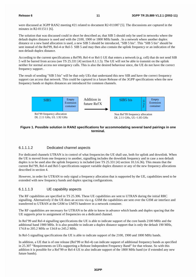
The solution that was discussed could in short be described as; that SIB 5 should only be used in networks where thedefault duplex distance is used and with the 2100, 1900 or 1800 MHz bands . In a network where another duplexdistance or a new band allocation is used, a new SIB 5 should be introduced, "SIB 5 bis". This "SIB 5 bis" should besent instead of the Rel'99, Rel-4 or Rel-5 SIB 5 and may then also contain the uplink frequency or an indication of thenon default duplex distance.
According to the current specifications a Rel'99, Rel-4 or Rel-5 UE that enters a network (e.g. cell) that do not send SIB5 will be barred from access (see TS 25.331 [4] section 8.1.1.5). The UE will not be able to transmit on the uplinkneither for normal access nor emergency calls. This is also the desired behaviour since, the UE do not have the correctfrequency support .
The result of sending "SIB 5 bis" will be that only UEs that understand this new SIB and have the correct frequencysupport can access that network. This could be captured in a future Release of the 3GPP specifications when the newfrequency bands or duplex distances are introduced for common channels.
EmptyExtensioncontainer
SIB5 bis EmptyExtensioncontainer
SIB5
Rel’99 frequency allocationDL 2.11 GHz, UL 1.92 GHz
Non Rel’99 frequency allocationDL 2.11 GHz, UL<1.85 GHz
UL
Freq.
Addition infuture Rel'X
Figure 1. Possible solution in RAN2 specifications for accommodating several band pairings in oneterminal.
6.1.1.1.2 Dedicated channel aspects
For dedicated channels UTRAN is in control of what frequencies the UE shall use, both for uplink and downlink. Whenthe UE is moved from one frequency to another, signalling includes the downlink frequency and in case a non defaultduplex is to be used also the uplink frequency is included (see TS 25.331 [4] section 10.3.6.36). This means that thecurrent Rel’99, Rel-4 and Rel-5 specifications support variable duplex distance or any of the new frequency allocationsdescribed in section 4.
However, in order for UTRAN to only signal a frequency allocation that is supported by the UE, capabilities need to beextended with new frequency bands and duplex spacing configurations.
6.1.1.1.3 UE capability aspects
The RF capabilities are specified in TS 25.306. These UE capabilities are sent to UTRAN during the initial RRCsignalling. Alternatively if the UE does an access via e.g. GSM the capabilities are sent over the GSM air interface andtransferred to UTRAN at the GSM to UMTS handover in a network container.
The RF capabilities are necessary for UTRAN to be able to know in advance which bands and duplex spacing that theUE supports prior to assignment of frequencies on a dedicated channel.
In Rel’99 and Rel-4 signalling specifications the UE is able to indicate support of the core bands 2100 MHz and theadditional band 1900 MHz. It is also possible to indicate a duplex distance support that is only the default 190 MHz,174.8 to 205.2 MHz or 134.8 to 245.2 MHz.
In Rel-5 signalling specifications the UE is able to indicate support of the 2100, 1900 and 1800 MHz bands.
In addition, a UE that is of one release (Rel’99 or Rel-4) can indicate support of additional frequency bands as specifiedin 25.307 “Requirements on UEs supporting a Release Independent Frequency Band” for that release. So with thisaddition it is possible for a Rel’99 or Rel-4 UE to also indicate support of the 1800 MHz band (or if extended any newfuture bands).

3GPP
3GPP TR 25.889 V1.2.1 (2002-11)12Release 6
6.1.1.1.4 Signalling summary
The following table summarises the status on signalling support in the Rel’99, Rel-4 and Rel-5 specifications for theexisting bands.
Table 2: Summary of signalling aspects for existing bands
Signalling aspect Band I (2100 MHz) Band II (1900 MHz) Band III (1800 MHz)Common channelsRel’99, Rel-4, Rel-5
Duplex distance = 190 MHz Duplex distance = 80 MHz Duplex distance = 95 MHz
Common channelswith a SIB 5 bis
Duplex distance flexible Duplex distance flexible Duplex distance flexible
Dedicated channelsRel’99, Rel-4, Rel-5
Duplex distance flexible Duplex distance flexible Duplex distance flexible
UE CapabilityRel’99, Rel-4
Signalling supported Signalling supported(Note 1)
Signalling supported onlywith additions according to
TS 25.307(Note 1)
UE CapabilityRel-5
Signalling supported Signalling supported(Note 1)
Signalling supported(Note 1)
Note 1. Signalling is currently not complete when it comes to signalling of degree of UE support of variable Tx/Rxfrequency separation for 1800 and 1900.
6.1.1.2 Frequency bands and hardware issues (RAN4)
6.1.1.2.1 Frequency bands
In TS 25.101 [7] (see section 5.3) the TX-RX frequency separation is specified for fixed separation of 190 MHz and 80MHz depending on the frequency band. Further it states that UTRA/FDD can support both fixed and variable transmitto receive frequency separation. And it also states that the use of other transmit to receive frequency separations inexisting or other frequency bands shall not be precluded. Similar text can be found in TS 25.104 [8] regarding the BaseStation.
When other frequency arrangements are introduced in 3GPP this section would be updated to list the TX-RX frequencyseparation for those frequency arrangements. Depending on the frequency arrangements there would also be otheradditions to RAN WG4 specifications, including that section 5.2 in 3GPP TS 25.101 [7] would be expanded by therelevant frequency bands.
The number of bands implemented in the UE is left to the manufacturers in agreement with operator partners.
6.1.1.2.2 RF performance
The impact to RF performance, firstly sensitivity, transmitter power and current drain, and secondly additionalinterference requirements, may require a change in the specifications. The variety of band combinations and the needfor non-compressed as well as compressed mode terminals leads to a high number of possibilities that must be takeninto account. It must be considered that RF performance specifications may be negatively affected, especially as thecomplexity in modes/bands increases.
It is therefore recommended to further study Rx and Tx RF performance before specifications can be finalised for UEssupporting multiple duplex spacings.
6.1.2 Examples of Implementation of variable duplex separation in oneterminal
The Table 1 in chapter 5 lists several band paring options in 1710 – 2200 MHz.
The UMTS core band is according to option 1 with 190 MHz fixed duplex separation as specified in 3GPP. Since notall options will be available in every region there will be a need to support more than one option in one terminal ifglobal roaming is envisaged. Based on the assumption that the UMTS core band will be used in several regions and will
3GPP
3GPP TR 25.889 V1.2.1 (2002-11)13Release 6
be available first on the market, one scenario is to combine option 1 with one or several other options. The followingscenarios have been chosen for further evaluation:
- Options 1 + 5 (+4)
- Options 1 + 2
The combination Options 1 + 3 has similar design impacts as Options 1 + 2.
Any of the proposed additional bands to the existing UMTS core band (Option 1) will require variable duplexseparation. The simplest configuration to consider is Option 1 + Option 5 configured in a compressed mode withDCS1800 or PCS1900.
- Options 1+5 (+4):
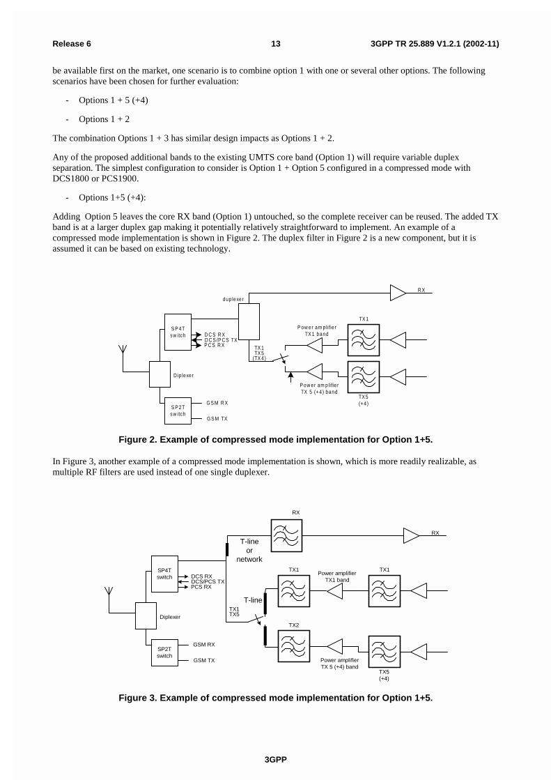
Adding Option 5 leaves the core RX band (Option 1) untouched, so the complete receiver can be reused. The added TXband is at a larger duplex gap making it potentially relatively straightforward to implement. An example of acompressed mode implementation is shown in Figure 2. The duplex filter in Figure 2 is a new component, but it isassumed it can be based on existing technology.
R X
TX 1TX 5
(TX 4)
S P 4Tsw itch
S P 2Tsw itch
P ow er am p lifie rTX 1 band
TX 5(+ 4)
TX 1
P ow er am p lifie rTX 5 (+ 4) band
dup lexer
D ip lexer
G S M R X
G S M TX
D C S R XD C S /P C S TXP C S R X
Figure 2. Example of compressed mode implementation for Option 1+5.
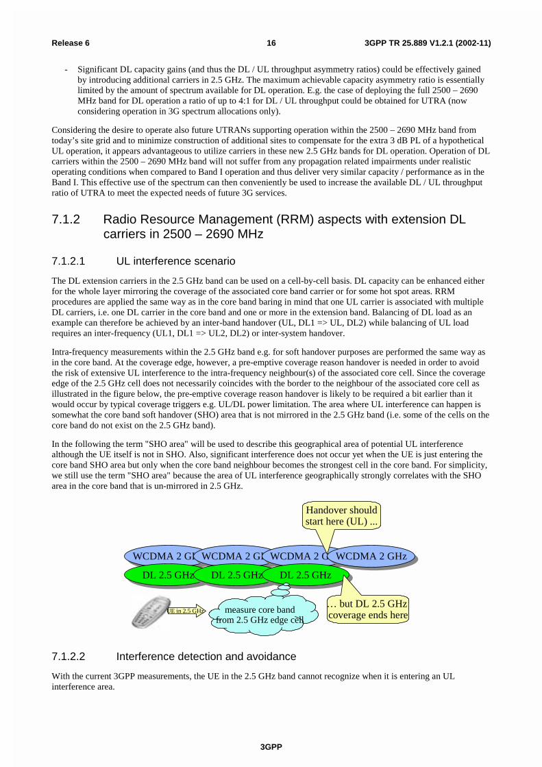
In Figure 3, another example of a compressed mode implementation is shown, which is more readily realizable, asmultiple RF filters are used instead of one single duplexer.
RX
TX1TX5
SP4Tswitch
SP2Tswitch
Power amplifierTX1 band
TX5(+4)
TX1
Power amplifierTX 5 (+4) band
Diplexer
GSM RX
GSM TX
DCS RXDCS/PCS TXPCS RX
TX1
TX2
RX
T-line
T-lineor
network
Figure 3. Example of compressed mode implementation for Option 1+5.

3GPP
3GPP TR 25.889 V1.2.1 (2002-11)14Release 6
Having an additional duplex mode results in additional losses to both the Tx and Rx sides of the WCDMA system. Asthe number of bands increases, the losses can be expected to increase even more. Furthermore if a non-compressedmode implementation is chosen for associating DCS1800 or PCS1900 to WCDMA, then the losses are likely to be evenmore important. In any case, these losses are likely to be bounded by [2] dB on either Tx or Rx side. Further studies areneeded so as to clearly evaluate the additional losses induced before specifications can be finalised.
- Options 1+2:
As diplexers and duplexers are carefully designed for specific frequencies, a classical implementation is to have oneduplexer for each band pairing supported by the terminal. This combination will thus require 2 duplexers with verydifferent requirements. Two complete receivers are needed for this combination. The general transceiver requirementsfrom GSM 1800 are different, so reuse of GSM 1800 RF components for UMTS on 1800 is not possible. Furtherstudies are needed before specifications can be finalised.
Note: The coexistence of Option 2 with the PCS1900 band is an open issue. The closeness of the bands will furthercomplicate the RF filter requirements and/or require large guard bands.
6.1.3 VDT Conclusion
Having terminals able to operate over several band pairings will facilitate roaming and will also enable operators toprovide service in multiple bands. Any vendor-specific implementation is suitable as long as RF performance arecarefully studied and specified. A choice is to be made between having the terminals implementing variable duplexseparation on a frequency block basis or on a frequency channel basis. It is however recommended not to have thisvariable duplex spacing capability mandatory in terminals.
6.2 Solutions for having a terminal accommodating frequencyband asymmetry
7 Examples for viable implementations of spectrumarrangements for UTRA FDD
Table 1 in chapter 5 list several band pairing options in the 1710 – 2200 MHz range. The implementation aspects ofthese were treated in chapter 6. The usage and implementation of the band 2500 – 2690 MHz will be discussed furtherin this chapter 7. And additional use of VDT for deployment for public indoor systems is shown in chapter 7.2.
7.1 DL usage of the new band 2500 – 2690 MHz in conjunctionwith the Band I for UTRA FDD
This clause discusses the usage of the 2500 - 2690 MHz spectrum on the assumption that it is used for for UTRA FDDDL in conjunction with an assumed operation of UTRA FDD within the 1920 - 1980 / 2110 – 2170 Band I (UTRAFDD core band). The following aspects shall be covered:
- Relevant radio network propagation and performance aspects for UL/DL operation within the 2.5 GHz band
- UTRA system requirements for efficiently supporting the 2500 – 2690 MHz band for asymmetric DL operation
- Required changes of current UTRA specifications in order to support efficient operation within the 2.5 GHzband

3GPP
3GPP TR 25.889 V1.2.1 (2002-11)15Release 6
7.1.1 Radio Network Performance Aspects regarding utilization of the2500 – 2690 MHz Band
In this clause we consider propagation and radio performance aspects related to the UTRA operating efficiency in the2.1, respective, 2.5 GHz bands.
7.1.1.1 Relevant Propagation Aspects for 2.5 GHz Band
There are no significant differences in the basic physical mechanisms of radio propagation in 2.5 GHz compared with 2GHz. All effects (PL, diffraction losses, building/wall penetration losses, etc) are understood to scale as a continousfunction of frequency and thus the basic modeling assumptions concerning radio propagation developed for the 2 GHzband can be re-used without much loss of accuracy.
However, and this is significant for the following discussion, there will be a larger path loss (PL) for the 2.5 GHz bandscompared to the 2 GHz . Assuming that the Okumura-Hata (OH) model (see e.g. [5]) is still valid around 2.5 GHz, wecan estimate the additional PL from the frequency dependent term in the OH model, B*log10(f), where B = 33.9 1:
dBBPL 57.2)1.2/5.2(10log* ==∆
Compared to operation in the 2 GHz bands, also additional cable losses for the 2.5 GHz signal relative to the one around2 GHz will occur at Node B sites - these are typically in the order of 1 … 3 dB/100 m, depending on the cable type andsize. Thus, for cable length of up to 20 m (typical for rooftop installations) the additional cable losses in 2.5 GHz will bein the order of 0.3 … 0.6 dB – these are the values used in the following calculations.
7.1.1.2 Impact of increased PL in the 2.5 GHz band on UTRA UL/DL Cell Coverage
Currently deployed urban UMTS cells are frequently co-sited with existing GSM cells and are typically designed for acoverage target on UL of about 64 – 144 kbps data and for DL of up to 384 kbps data, thus matching the GSM cellfootprint with typical PLs of some 150 – 155 dB. Typically an UL load factor of 0.3 … 0.6 is assumed resulting in anequivalent noise rise of some 1.5 … 4 dB. For DL larger load factors of up to 0.8 are frequently assumed. Under these(typical) conditions the UTRA UL becomes coverage and the DL capacity (or interference) limited, for a more detaileddiscussion see e.g. references [15,16].
It is important to note now that the increased PL in the 2.5 GHz band of approximately 3 dB effects the UTRA UL/DLcell coverage limitations. In fact, an additional PL will not affect an interference limited link such as the UTRA DLtypically is. However, the UTRA coverage limited UL (data coverage being essentially limited by the limited UE Txpower) would be adversively affected by the increased PL if deployed within the new 2.5 GHz band. In order to retainthe same cell coverage as in the 2 GHz Band I, additional and costly means to recover this 3 dB PL loss would need tobe deployed (e.g. UE with higher power class, smart antenna solutions in Node B, etc).
A more detailed case study analysis has been conducted to illustrate this dynamics and the results are presented inAppendix A. When introducing additional carriers in the 2.5 GHz band to share the DL traffic with the Band I carriersthe following observations can be made (see also to Fig.1 in the Appendix A):
- at each DL throughput point, the fractional DL load value is equal for 2.1 / 2.5 GHz carriers, in particular for thepole capacity (DL load = 1). No DL capacity is lost due to the extra PL. This is a consequence from the fact thatthe DL load equation (see [15], p. 159) does not depend on the path loss.
- The introduction of each additional DL 2.5 GHz carrier adds the same DL capacity as a corresponding Band Icarrier would do
- The introduction of each additional DL 2.5 GHz carriers increases the achievable DL / UL throughputasymmetry of the system
- There appears to be no need for power compensating the additional 3 dB PL on the 2.5 GHz carrier for coveragereasons as there is ample margin for DL coverage available
- As long as the DL / UL throughput asymmetry is high enough, the UL can carry the additional traffic to supportthe 2.5 GHz carrier with no adverse effect on the cell size / coverage
1 This value for B is expected to be larger for 2.5 GHz, thus in here we may underestimate the increase of the PL compared to 2.1 GHz
3GPP
3GPP TR 25.889 V1.2.1 (2002-11)16Release 6
- Significant DL capacity gains (and thus the DL / UL throughput asymmetry ratios) could be effectively gainedby introducing additional carriers in 2.5 GHz. The maximum achievable capacity asymmetry ratio is essentiallylimited by the amount of spectrum available for DL operation. E.g. the case of deploying the full 2500 – 2690MHz band for DL operation a ratio of up to 4:1 for DL / UL throughput could be obtained for UTRA (nowconsidering operation in 3G spectrum allocations only).
Considering the desire to operate also future UTRANs supporting operation within the 2500 – 2690 MHz band fromtoday’s site grid and to minimize construction of additional sites to compensate for the extra 3 dB PL of a hypotheticalUL operation, it appears advantageous to utilize carriers in these new 2.5 GHz bands for DL operation. Operation of DLcarriers within the 2500 – 2690 MHz band will not suffer from any propagation related impairments under realisticoperating conditions when compared to Band I operation and thus deliver very similar capacity / performance as in theBand I. This effective use of the spectrum can then conveniently be used to increase the available DL / UL throughputratio of UTRA to meet the expected needs of future 3G services.
7.1.2 Radio Resource Management (RRM) aspects with extension DLcarriers in 2500 – 2690 MHz
7.1.2.1 UL interference scenario
The DL extension carriers in the 2.5 GHz band can be used on a cell-by-cell basis. DL capacity can be enhanced eitherfor the whole layer mirroring the coverage of the associated core band carrier or for some hot spot areas. RRMprocedures are applied the same way as in the core band baring in mind that one UL carrier is associated with multipleDL carriers, i.e. one DL carrier in the core band and one or more in the extension band. Balancing of DL load as anexample can therefore be achieved by an inter-band handover (UL, DL1 => UL, DL2) while balancing of UL loadrequires an inter-frequency (UL1, DL1 => UL2, DL2) or inter-system handover.
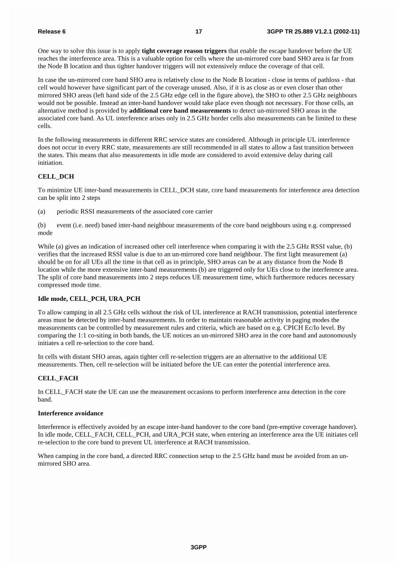
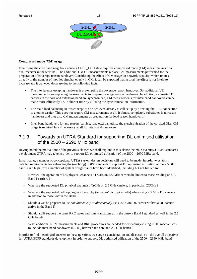
Intra-frequency measurements within the 2.5 GHz band e.g. for soft handover purposes are performed the same way asin the core band. At the coverage edge, however, a pre-emptive coverage reason handover is needed in order to avoidthe risk of extensive UL interference to the intra-frequency neighbour(s) of the associated core cell. Since the coverageedge of the 2.5 GHz cell does not necessarily coincides with the border to the neighbour of the associated core cell asillustrated in the figure below, the pre-emptive coverage reason handover is likely to be required a bit earlier than itwould occur by typical coverage triggers e.g. UL/DL power limitation. The area where UL interference can happen issomewhat the core band soft handover (SHO) area that is not mirrored in the 2.5 GHz band (i.e. some of the cells on thecore band do not exist on the 2.5 GHz band).
In the following the term "SHO area" will be used to describe this geographical area of potential UL interferencealthough the UE itself is not in SHO. Also, significant interference does not occur yet when the UE is just entering thecore band SHO area but only when the core band neighbour becomes the strongest cell in the core band. For simplicity,we still use the term "SHO area" because the area of UL interference geographically strongly correlates with the SHOarea in the core band that is un-mirrored in 2.5 GHz.
WCDMA 2 GHzWCDMA 2 GHz
DL 2.5 GHzDL 2.5 GHz
WCDMA 2 GHzWCDMA 2 GHz
DL 2.5 GHzDL 2.5 GHz
WCDMA 2 GHzWCDMA 2 GHz
DL 2.5 GHzDL 2.5 GHz
WCDMA 2 GHzWCDMA 2 GHz
Handover shouldstart here (UL) ...
… but DL 2.5 GHz coverage ends hereUE in 2.5 GHz measure core band
from 2.5 GHz edge cell
7.1.2.2 Interference detection and avoidance
With the current 3GPP measurements, the UE in the 2.5 GHz band cannot recognize when it is entering an ULinterference area.
3GPP
3GPP TR 25.889 V1.2.1 (2002-11)17Release 6
One way to solve this issue is to apply tight coverage reason triggers that enable the escape handover before the UEreaches the interference area. This is a valuable option for cells where the un-mirrored core band SHO area is far fromthe Node B location and thus tighter handover triggers will not extensively reduce the coverage of that cell.
In case the un-mirrored core band SHO area is relatively close to the Node B location - close in terms of pathloss - thatcell would however have significant part of the coverage unused. Also, if it is as close as or even closer than othermirrored SHO areas (left hand side of the 2.5 GHz edge cell in the figure above), the SHO to other 2.5 GHz neighbourswould not be possible. Instead an inter-band handover would take place even though not necessary. For those cells, analternative method is provided by additional core band measurements to detect un-mirrored SHO areas in theassociated core band. As UL interference arises only in 2.5 GHz border cells also measurements can be limited to thesecells.
In the following measurements in different RRC service states are considered. Although in principle UL interferencedoes not occur in every RRC state, measurements are still recommended in all states to allow a fast transition betweenthe states. This means that also measurements in idle mode are considered to avoid extensive delay during callinitiation.
CELL_DCH
To minimize UE inter-band measurements in CELL_DCH state, core band measurements for interference area detectioncan be split into 2 steps
(a) periodic RSSI measurements of the associated core carrier
(b) event (i.e. need) based inter-band neighbour measurements of the core band neighbours using e.g. compressedmode
While (a) gives an indication of increased other cell interference when comparing it with the 2.5 GHz RSSI value, (b)verifies that the increased RSSI value is due to an un-mirrored core band neighbour. The first light measurement (a)should be on for all UEs all the time in that cell as in principle, SHO areas can be at any distance from the Node Blocation while the more extensive inter-band measurements (b) are triggered only for UEs close to the interference area.The split of core band measurements into 2 steps reduces UE measurement time, which furthermore reduces necessarycompressed mode time.
Idle mode, CELL_PCH, URA_PCH
To allow camping in all 2.5 GHz cells without the risk of UL interference at RACH transmission, potential interferenceareas must be detected by inter-band measurements. In order to maintain reasonable activity in paging modes themeasurements can be controlled by measurement rules and criteria, which are based on e.g. CPICH Ec/Io level. Bycomparing the 1:1 co-siting in both bands, the UE notices an un-mirrored SHO area in the core band and autonomouslyinitiates a cell re-selection to the core band.
In cells with distant SHO areas, again tighter cell re-selection triggers are an alternative to the additional UEmeasurements. Then, cell re-selection will be initiated before the UE can enter the potential interference area.
CELL_FACH
In CELL_FACH state the UE can use the measurement occasions to perform interference area detection in the coreband.
Interference avoidance
Interference is effectively avoided by an escape inter-band handover to the core band (pre-emptive coverage handover).In idle mode, CELL_FACH, CELL_PCH, and URA_PCH state, when entering an interference area the UE initiates cellre-selection to the core band to prevent UL interference at RACH transmission.
When camping in the core band, a directed RRC connection setup to the 2.5 GHz band must be avoided from an un-mirrored SHO area.
3GPP
3GPP TR 25.889 V1.2.1 (2002-11)18Release 6
2GHz2GHz
DL 2.5GHzDL 2.5GHz
2GHz2GHz
x
Compressed mode (CM) usage
Identifying the core band neighbours during CELL_DCH state requires compressed mode (CM) measurements or adual-receiver in the terminal. The additional CM UE measurements replace CM measurements performed for thepreparation of coverage reason handover. Considering the effect of CM usage on network capacity, which relatesdirectly to the number of mobiles simultaneously in CM, it can be expected that in total the effect is not likely toincrease and it can even decrease due to the following facts.
• The interference escaping handover is pre-empting the coverage reason handover. So, additional UEmeasurements are replacing measurements to prepare coverage reason handovers. In addition, as co-sited DLcarriers in the core and extension band are synchronized, CM measurements for inter-band handovers can bemade more efficiently i.e. in shorter time by utilizing the synchronization information.
• The main load balancing in this concept can be achieved already at call setup by directing the RRC connectionto another carrier. This does not require CM measurements at all. It almost completely substitutes load reasonhandovers and thus also CM measurements as preparation for load reason handovers.
• Inter-band handovers for any reason (service, load etc.) can utilise the synchronisation of the co-sited DLs. CMusage is required less if necessary at all for inter-band handovers.
7.1.3 Towards an UTRA Standard for supporting DL optimised utilisationof the 2500 – 2690 MHz band
Having noted the motivations of the previous clauses we shall explore in this clause the main avenues a 3GPP standardsdevelopment UTRA may take in order to support DL optimised utilisation of the 2500 – 2690 MHz band.
In particular, a number of conceptional UTRA system design decisions will need to be made, in order to establishdetailed requirements for enhancing the (evolving) 3GPP standards to support DL optimised utilisation of the 2.5 GHzband. On a high level a number of system design issues have been identified, including but not limited to:
- How will the operation of DL physical channels / TrCHs on 2.5 GHz carriers be linked to those residing on ULBand I carriers ?
- What are the supported DL physical channels / TrCHs on 2.5 GHz carriers, in particular CCCHs ?
- What are the supported cell topologies / hierarchy (ie macro/micro/pico cells) when using 2.5 GHz DL carriersin addition to those within the Band I?
- Should a UE be prepared to use simultaneously or alternatively use a 2.5 GHz DL carrier with/to a DL carrieractive in the Band I?
- Should a UE support the same RRC states and state transitions as in the current Band I standard as well in the 2.5GHz band?
- What additional RRM measurements and RRC procedures are needed for extending existing IFHO mechanismsto include inter-band handovers (IBHO) between the core and 2.5 GHz bands?
In order to find meaningful answers to these questions we suggest consideration and discussion on the overall objectivesfor UTRA 3GPP standards development in order to support DL optimised utilisation of the 2500 – 2690 MHz band.

3GPP
3GPP TR 25.889 V1.2.1 (2002-11)19Release 6
7.1.3.1 Overall Objectives for UTRA 3GPP standards development to support DLoptimised utilisation of the 2500 – 2690 MHz band
We propose that the following overall objectives shall be taken into account when developing the 3GPP UTRAspecifications for supporting DL optimised utilisation of the 2500 – 2690 MHz band:
- No or minimum restrictions in the utilization of services and features available from the (evolving) 3GPP UTRABand I specifications, including those currently under development (such as e.g. HSDPA). There shall be fullflexibility in locating services and features between the core and 2.5 GHz bands primarily limited by the basiccapability of UE and Node B to operate in the 2500 – 2690 MHz band (in addition to the Band I).
- Reuse of all standard UTRA TrCH and physical channels in 2.5 GHz DL carriers, including those currentlyunder development (such as e.g. HSDPA). The goal shall be that the required capabilities and mechanisms forUTRA to operate in the 2500 – 2690 MHz band are orthogonal to the features developed for the UTRA Band Ispecifications, in order to simplify UTRA standards development and minimise adverse affects from featureinteractions.
- Possibility to implement the 2.5 GHz DL capability into UE and UTRAN Band I product families at low costand with comparably small development effort. In particular, it shall be possible for the UE to retain low costsingle-receiver architectures (as supported by today’s Band I UTRA standard) also for the 2.5 GHz DLenhancement. This is seen as important to migrate mass-market data traffic into the 2.5 GHz band.
- Support for flexible range of achievable DL-UL traffic asymmetry, limited by the available spectrum (up to 1:4ratio) only
- Spectrally efficient utilization of carriers residing within the additional 2.5 GHz spectrum in order to supportincreased DL throughput
- No or minimal negative impact (other than the required traffic handling capacity) on the operation andperformance of the utilized UL carriers in the Band I
- Smooth evolution of operational Band I UTRANs and operational and network planning practices when utilizingadditional 2.5 GHz DL carriers. A 2.5 GHz enabled UTRAN shall not be a “new mode”, but an additionalcapacity enhancing capability which does not require to enter a new significant learning curve. Adding a 2.5GHz DL carriers to a deployed UTRAN should be an effort comparable to adding an additional carrier in theBand I.
7.1.3.2 Towards a technical framework for extending UTRA to support DL optimisedutilisation of the 2500 – 2690 MHz band
We feel that the above overall objectives for development of the 3GPP UTRA standard for supporting DL optimisedutilisation of the 2500 – 2690 MHz band can be effectively met when making the following technical workingassumptions the starting point for further concept development:
1) Each additional 2.5 GHz DL carrier should be seen simply as an additional “other-frequency layer” for DLcapacity addition, matched to one of the corresponding layers already existing within the Band I. The additionallayer(s) within the 2.5 GHz band could thus “mirror” either a macro, micro, or indoor/pico layer implemented inthe Band I in a certain geographical area. This concept does not support eg a 2.5 GHz DL micro cell matchedwith a Band I macro cell UL2, however, there could be a 2.5 GHz micro cell layer coverage-matched to a Band Imicro cell layer. Mirroring an existing Band I UL/DL cell footprint/layer in 2.5 GHz, is the key for the simplicityin the areas of
- Re-using to maximum extent existing UTRA procedures and mechanisms (cell reselection, IFHO, RRMmeasurements and control); minimal impact on the UTRA standard
- Ease of radio network evolution; utilization of the additional 2.5 GHz cells is then building on known celldesigns / concepts / cell coverage plans and operational practices already available within the Band I UTRAN
- Full leverage of existing (mostly proprietary) RRM features for traffic management between cell layers
2 this is for following reason: for soft HO detection UL and DL cell coverage should be similar, in particular we should be able to derive the need forsoft HO from the UL perspective (for interference avoidance) from measurements of CPICH Ec/Io measurements obtained from 2.5 GHzcarriers
3GPP
3GPP TR 25.889 V1.2.1 (2002-11)20Release 6
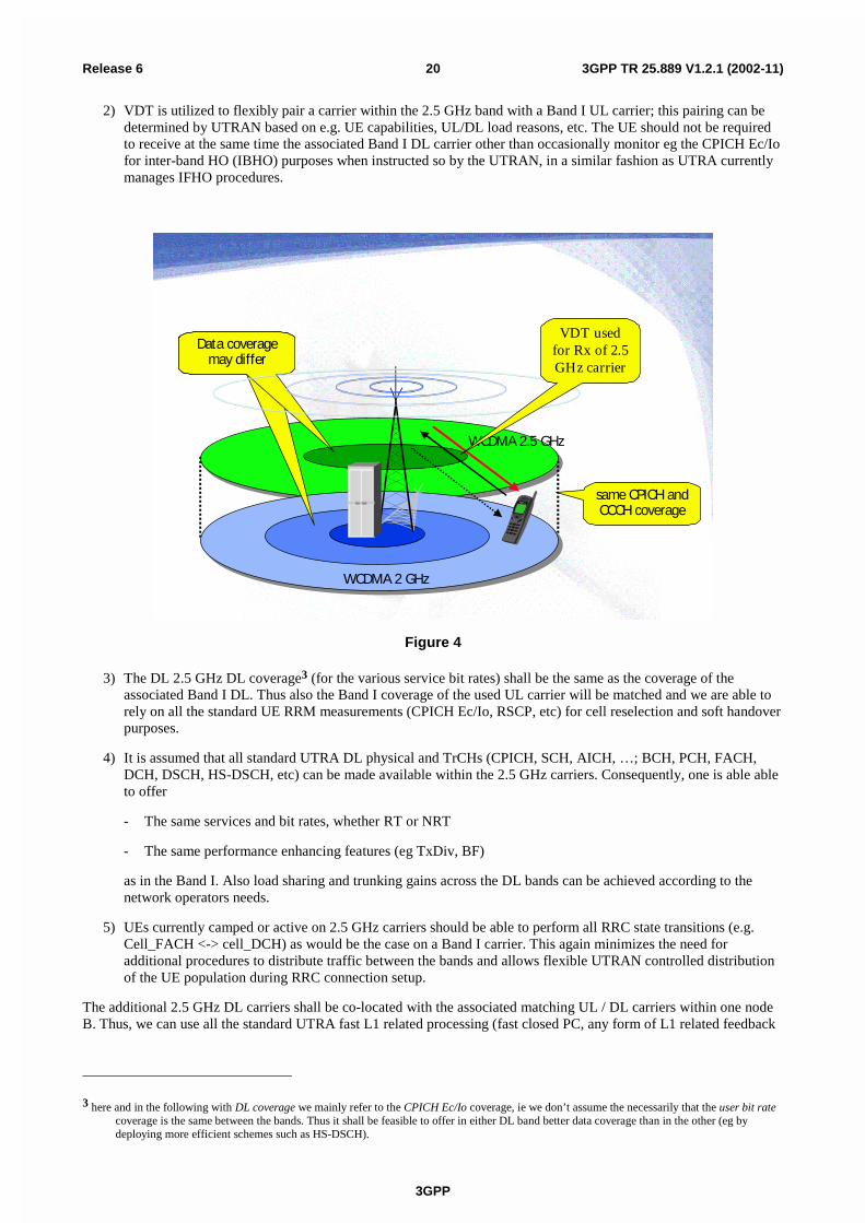
2) VDT is utilized to flexibly pair a carrier within the 2.5 GHz band with a Band I UL carrier; this pairing can bedetermined by UTRAN based on e.g. UE capabilities, UL/DL load reasons, etc. The UE should not be requiredto receive at the same time the associated Band I DL carrier other than occasionally monitor eg the CPICH Ec/Iofor inter-band HO (IBHO) purposes when instructed so by the UTRAN, in a similar fashion as UTRA currentlymanages IFHO procedures.
same CPICH and CCCH coverage
WCDMA 2 GHz
WCDMA 2.5 GHz
Data coverage may differ
VDT used for Rx of 2.5 GHz carrier
Figure 4
3) The DL 2.5 GHz DL coverage3 (for the various service bit rates) shall be the same as the coverage of theassociated Band I DL. Thus also the Band I coverage of the used UL carrier will be matched and we are able torely on all the standard UE RRM measurements (CPICH Ec/Io, RSCP, etc) for cell reselection and soft handoverpurposes.
4) It is assumed that all standard UTRA DL physical and TrCHs (CPICH, SCH, AICH, …; BCH, PCH, FACH,DCH, DSCH, HS-DSCH, etc) can be made available within the 2.5 GHz carriers. Consequently, one is able ableto offer
- The same services and bit rates, whether RT or NRT
- The same performance enhancing features (eg TxDiv, BF)
as in the Band I. Also load sharing and trunking gains across the DL bands can be achieved according to thenetwork operators needs.
5) UEs currently camped or active on 2.5 GHz carriers should be able to perform all RRC state transitions (e.g.Cell_FACH <-> cell_DCH) as would be the case on a Band I carrier. This again minimizes the need foradditional procedures to distribute traffic between the bands and allows flexible UTRAN controlled distributionof the UE population during RRC connection setup.
The additional 2.5 GHz DL carriers shall be co-located with the associated matching UL / DL carriers within one nodeB. Thus, we can use all the standard UTRA fast L1 related processing (fast closed PC, any form of L1 related feedback
3 here and in the following with DL coverage we mainly refer to the CPICH Ec/Io coverage, ie we don’t assume the necessarily that the user bit ratecoverage is the same between the bands. Thus it shall be feasible to offer in either DL band better data coverage than in the other (eg bydeploying more efficient schemes such as HS-DSCH).

3GPP
3GPP TR 25.889 V1.2.1 (2002-11)21Release 6
signaling typically carried on DPCCHs) between UL-DL4. The philosophy is to treat the additional 2.5 GHz DL carrierjust as any other additional Band I carrier, except for the obvious items related to the different carrier frequency.Certainly this list of technical assumptions is neither complete, nor “canonical”, however, we believe these are anindication of the kind of items 3GPP would be required to study further when developing an efficient UTRA support forthe new 2.5 GHz bands.
7.1.4 Needed Additions to the UTRA Standard for supporting DLoptimised utilisation of the 2500 – 2690 MHz band
It is perhaps premature to list the precise impact on the 3GPP UTRA specifications, before the overall system concepthas been agreed and stabilized.
However, assuming the UTRAN support for DL optimised utilisation of the 2500 – 2690 MHz band would be buildwithin the framework of Sect. 3.3, the most significant revisions are believed to be required for the following TSs:
TS 25.101 UE Radio Transmission and Reception (FDD)
UE RF requirements for 2.5 GHz band
TS 25.133 Requirements for Support of Radio Resource Management (FDD),
Additional RRM measurements for IBHO
TS 25.104 UTRA (BS) FDD; Base station Radio Transmission and Reception,
Node B RF requirements for 2.5 GHz band
TS 25.304 UE Procedures in Idle Mode,
Extending the cell selection/reselection procedures for to support the 2.5 GHz band
TS 25.331 Radio Resource Control (RRC) Protocol Specification,
“cleaning up” some of the missing parameters in RRC signalling required to fully utilize VDT, e.g. currently only fixeddistance duplexing for UL/DL CCCHs is supported
As can be seen from the list, this SI will also impact other WG’s than TSG RAN WG4 alone.
7.1.5 Summary of section 7.1 for usage of the new band in 2500 – 2690 MHzin conjunction with the Band I for UTRA
The section 7.1 has presented key system considerations and requirements for 3GPP UTRA standard developmenttowards supporting DL optimised utilisation of the 2500 – 2690 MHz band with the goal to obtain a capacity enhancingcomplement for UTRA operating in the Band I.
The main findings presented in this section were:
- There appears to be evidence that the nature of future mobile traffic points towards an increased asymmetry ofDL/UL traffic volume and that the use of the 2.5 GHz bands to increase DL capacity may be required to sustainthese future traffic needs at reasonable a cost
- There appears to be evidence that the use of the 2500 – 2690 MHz band for DL transmission is preferred fromthe perspective of UTRA radio system performance and propagation related reasons
- It appears entirely feasible to augment the existing UTRA Band I standard in order to support DL optimisedutilisation of the 2500 – 2690 MHz band with reasonable work effort effecting the specifications only in a fewlocalized areas (RRM measurements, RRC procedures)
- Use of VDT is an essential technological element in providing this solution
4 Otherwise there is either a large impact on 3GPP standard or one would need some RF-over-fiber type of concept for remote RF heads, however,then still all the DL BB processing would to be in same Node B as the UL BB.
3GPP
3GPP TR 25.889 V1.2.1 (2002-11)22Release 6
- Such an enhanced the UTRA standard would be able to offer a large degree of DL / UL traffic handlingasymmetry at reasonable complexity and cost
7.2 Use of VDT for deployment of public indoor systems
7.2.1 Introduction to the scenario
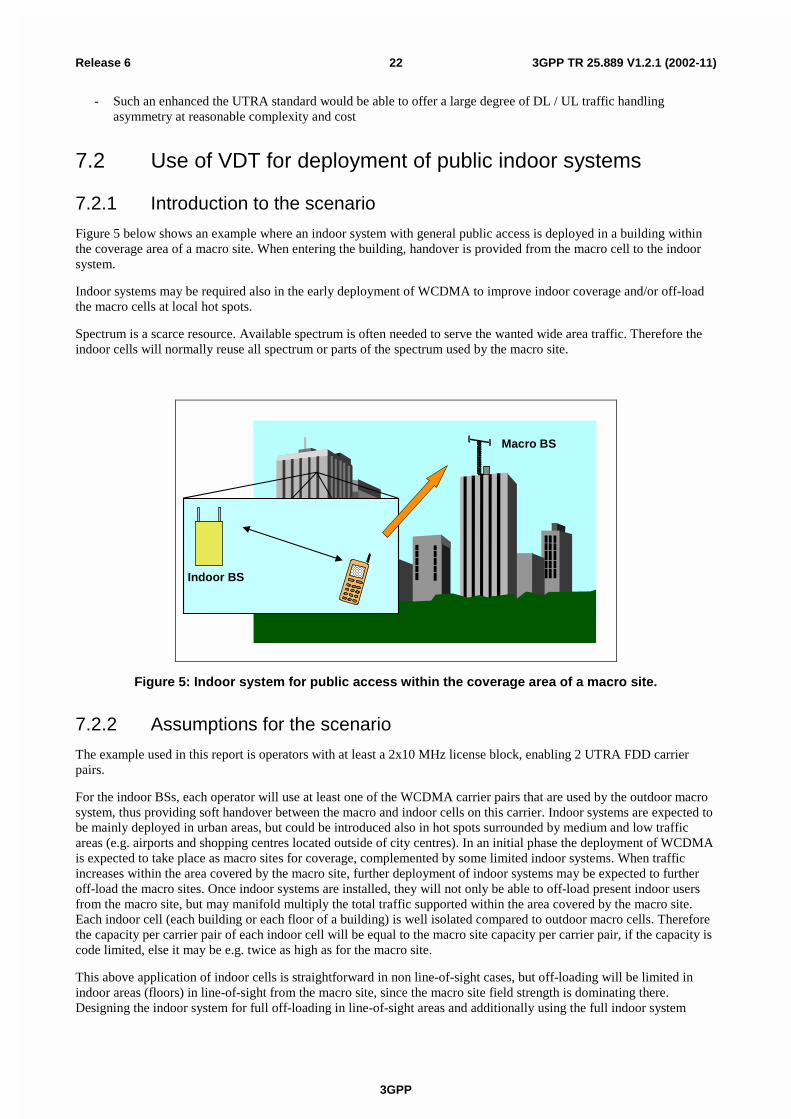
Figure 5 below shows an example where an indoor system with general public access is deployed in a building withinthe coverage area of a macro site. When entering the building, handover is provided from the macro cell to the indoorsystem.
Indoor systems may be required also in the early deployment of WCDMA to improve indoor coverage and/or off-loadthe macro cells at local hot spots.
Spectrum is a scarce resource. Available spectrum is often needed to serve the wanted wide area traffic. Therefore theindoor cells will normally reuse all spectrum or parts of the spectrum used by the macro site.
Indoor BS
Macro BS
Figure 5: Indoor system for public access within the coverage area of a macro site.
7.2.2 Assumptions for the scenario
The example used in this report is operators with at least a 2x10 MHz license block, enabling 2 UTRA FDD carrierpairs.
For the indoor BSs, each operator will use at least one of the WCDMA carrier pairs that are used by the outdoor macrosystem, thus providing soft handover between the macro and indoor cells on this carrier. Indoor systems are expected tobe mainly deployed in urban areas, but could be introduced also in hot spots surrounded by medium and low trafficareas (e.g. airports and shopping centres located outside of city centres). In an initial phase the deployment of WCDMAis expected to take place as macro sites for coverage, complemented by some limited indoor systems. When trafficincreases within the area covered by the macro site, further deployment of indoor systems may be expected to furtheroff-load the macro sites. Once indoor systems are installed, they will not only be able to off-load present indoor usersfrom the macro site, but may manifold multiply the total traffic supported within the area covered by the macro site.Each indoor cell (each building or each floor of a building) is well isolated compared to outdoor macro cells. Thereforethe capacity per carrier pair of each indoor cell will be equal to the macro site capacity per carrier pair, if the capacity iscode limited, else it may be e.g. twice as high as for the macro site.
This above application of indoor cells is straightforward in non line-of-sight cases, but off-loading will be limited inindoor areas (floors) in line-of-sight from the macro site, since the macro site field strength is dominating there.Designing the indoor system for full off-loading in line-of-sight areas and additionally using the full indoor system
3GPP
3GPP TR 25.889 V1.2.1 (2002-11)23Release 6
capacity in line-of-sight areas may cause increased up-link interference for the macro site. This interference can beeliminated by the use of Variable Duplex Technology.
A scenario without VDT is described in Table 2. The table indicates columns for areas with different average trafficdensities from high to low. In each type of area there could be hot spots where an indoor system is beneficial. Dx andUy are notations for downlink and up-link carriers. Dx-Ux indicates a coupled pair with the standard duplex separation(190 MHz for band I). The terminology Initial Phase means that providing coverage is most important. Carrier pairswithin parenthesis indicate possible application, but the traffic requirements do not require any special measures toprotect the macro cell from up-link interference. In the Second Phase traffic requirements increases also for indoorsystems. This may lead to increased up-link interference to the macro site. See next section.
Table 2:Scenario without VDT. Dx-Ux are coupled Downlink/Uplink carrier pairs. Pairs in brackets arewith limited or no traffic.
High traffic areas Medium trafficareas
Low traffic areas CommentPhase
IndoorSystems
Macro IndoorSystems
Macro IndoorSystems
Macro
Initial (D1-U1) D1-U1(D2-U2)
(D1-U1) D1-U1 (D1-U1) D1-U1 Coverage only. Mainly D1/U1.
Second D1-U1 D1-U1D2-U2
(D1-U1) D1-U1 (D1-U1) D1-U1 Traffic increases. IndoorSystems are introduced. D2/U2is added.
7.2.3 UL interference from increased traffic in indoor system
When assessing the impact of additional up-link, UL, interference, it is important to note that the WCDMA macro sitecapacity normally is downlink, DL, limited for symmetric (speech) traffic. We could furthermore assume that therecould substantial asymmetric (internet) traffic as well. This would make the WCDMA capacity even more DL limitedwhen using a symmetric DL/UL spectrum allocation. Thus we could assume that the macro site could stand additionalinterference on the UL before the macro site capacity is affected.
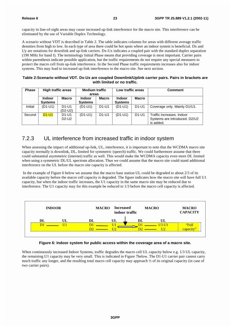
In the example of Figure 6 below we assume that the macro base station UL could be degraded to about 2/3 of itsavailable capacity before the macro cell capacity is degraded. The figure indicates how the macro site will have full U1capacity, but when the indoor traffic increases, the U1 capacity in the same macro site may be reduced due tointerference. The U1 capacity may for this example be reduced to 1/3 before the macro cell capacity is affected.
INDOOR MACRO MACRO MACROCAPACITY
DL UL DL UL DL ULD1 U1 D1 U1 D1 1/3 U1
D2 U2 D2 U2“Full
capacity”
Increasedindoor traffic
Figure 6: Indoor system for public access within the coverage area of a macro site.
When continuously increased Indoor Systems, traffic degrades the macro cell UL capacity below e.g. 1/3 UL capacity,the remaining U1 capacity may be very small. This is indicated in Figure 7below. The D1-U1 carrier pair cannot carrymuch traffic any longer, and the resulting total macro cell capacity may approach ½ of its original capacity (in case oftwo carrier pairs).

3GPP
3GPP TR 25.889 V1.2.1 (2002-11)24Release 6
INDOOR MACRO MACRO MACROCAPACITY
DL UL DL UL DL ULD1 U1 D1 U1 D1
D2 U2 D2 U2Totally halfcapacity**
Furtherincreasedindoor traffic
Figure 7: Indoor system for public access within the coverage area of a macro site.
7.2.4 Controlling the UL interference with the use of VDT
A suggested migration path to full utilization of both Indoor Systems and macro cell traffic capabilities is to de-coupling of the macro base station DL/UL frequency associations using VDT as indicated in Figure 4. The D1 carrier isallowed to be associated with U1 and U2.
INDOOR MACRO MACRO MACROCAPACITY
DL UL DL UL DL ULD1 U1 D1 U1 D1
D2 U2 D2 U2Half totalcapacity
D1 U1 D1 U1 D1D2 U2 D2 U2
Full DLcapacity*
Further increased indoor traffic
Figure 8: Indoor system for public access within the coverage area of a macro site.
Further increased aggregated indoor traffic may almost block U1. In this case carrier pairs D1-U2 and D2-U2 will carrythe macro site traffic. Full macro site capacity equals full total capacity if DL traffic > 2 times the UL traffic, whichmay be a typical case.
This migration path requires mobiles that can perform handover between cells with different duplex distances. Suchfunctionality is supported by the WCDMA standard.
The concept provides for a mix of handsets with and without VDT during a transition period. Handsets without VDTwill in the macro site mainly use D2-U2. (VDT could additionally if wanted also be applied for the indoor system byadding D2-U1).
This solution provides full Indoor Systems and macro cell capacity. The capacity of the indoor systems can be increasedas much as wanted by adding equipment (e.g. cell splitting) without damaging the planned macro site coverage.
Table 3 below is an extension of Table 2. The Third Phase with de-coupling of the macro base station DL/UL frequencyassociations, where macro base stations using carriers D1-U1 and D2-U2 to also support D1-U2, has been added. Thisphase is relevant when the indoor system traffic (aggregated traffic over the coverage area of a macro site) has furtherincreased, so that the U1 carrier at the macro site is substantially interfered.

3GPP
3GPP TR 25.889 V1.2.1 (2002-11)25Release 6
Table 3. Scenario with VDT. Dx-Ux are coupled Downlink/Uplink carrier pairs. Pairs in brackets arewith limited or no traffic.
High traffic areas Medium traffic areas Low traffic areas CommentPhaseIndoor
SystemsMacro Indoor
SystemsMacro Indoor
SystemsMacro
Initial (D1-U1) D1-U1(D2-U2)
(D1-U1) D1-U1 (D1-U1) D1-U1 Coverage only. D1/U1 only. Fullmacro capacity/coverage.
Second D1-U1 D1-U1D2-U2
(D1-U1) D1-U1 (D1-U1) D1-U1 Traffic increases, need for IndoorSystems. D2/U2 added. Fullmacro capacity/coverage.
Third D1-U1 D1-U1\
D2-U2
D1-U1 D1-U1D2-U2
D1-U1 D1-U1 Aggregated indoor trafficincreases further, add D1-U2association.Full macrocapacity/coverage.
Figure 9 below gives an example of a graphic representation of the three phases of evolution for the macro site trafficon carrier pair D1-U1 shown in Table 3 and Figure 8.
N is the maximum traffic on D1-U1 in the macro site, supposing no limiting interference on U1.
An indoor cell (a building or e.g each floor of a building) is well isolated compared to outdoor macro cells.
Therefore the maximum capacity on D1-U1 is supposed to be between N and 2N at each indoor cell, depending onwhether the capacity is code limited or not. In the example of Figure 9 the total aggregated indoor traffic reaches about6N before the macro site capacity becomes UL limited. At further increase of indoor traffic the D1-U1 macro site trafficwould approach zero, unless the D1 is de-coupled to allow D1-U2 pairing as shown in figure 8 and table 3.
The 6N break point is arbitrary. It could be much higher when all indoor systems are designed without trying to "force"off-loading the LOS parts of the building. NLOS areas could carry e.g. 20 N or higher aggregated traffic from severalsystems, without affecting the macro site. However, a single indoor system close to the macro site, where users on LOSfloors are “forced” to connect to the indoor system, and the full indoor system capacity is utilized, could severely affectthe macro site UL.
Traffic within the macro site coverage areausing one common DL carrier (D 1)
Time
N
2N
3N
4N
5N
6N Aggregated traffic fromall indoor system within
the macro site coverage area
Aggregated traffic inmacro cell system
Outdoor macro and indoor systemshare uplink carrier U1
First installation of indoor system
Macro system is UL limited
Macro system is DL limited.Assume 1/3 of UL capacity utilized
Implement VDT migration path
Separating UL carrier macro/indoors
Figure 9. Example of traffic evolution for the macro site and the indoor systems within the coveragearea of a macro site.
3GPP
3GPP TR 25.889 V1.2.1 (2002-11)26Release 6
7.2.5 Summary of the use of VDT for deployment for public indoorsystems
This section 7.2 describes one opportunity for using VDT in a scenario with macro and indoor cells using a common setof carrier frequencies. A prerequisite for the method to be implemented is that the Variable Duplex Technology hasbeen developed and ready to be used in commercially available terminals.
The method suggests a de-coupling of the nominal up-link and down-link carrier associations, to provide full off-loading of macro cells and utilising the full additional capacity provided by indoor cells. VDT is implemented allowingfor two downlink carriers to be coupled to one up-link. As a result, a serving macro base station can be capable ofmanifold multiplying the total traffic within a WCDMA macro cell area.
As a summary, the main objectives of the proposed method using VDT is to:
- give improved spectrum utilisation
- provide capacity of the indoor systems, that can be increased as much as wanted by adding equipment (e.g. cellsplitting) without damaging the planned macro site coverage
- admit for a smooth transition of cellular network when traffic increases
7.2.6 Handover between cells with different duplex spacing
In the proposed scheme for use of VDT in public indoor systems, we have macro cells where two downlink carriers arecoupled to one uplink carrier. Depending on the downlink carrier used, the duplex distance will be different. We willthus get handover situations where the target cell for handover will have the same downlink frequency available, but notthe same uplink frequency. A normal soft handover procedure cannot be used in this case.
In the WCDMA handover procedures there exists a procedure called "Physical channel reconfiguration". Thisprocedure indicates both the UL and DL frequencies to which the handover shall be made. Just taking the WCDMAstandard as it is means that handover between cells with different duplex distances will be executed as hard handoverusing the "Physical channel reconfiguration" procedure as described in [9]. The situation can thus be handled withexisting procedures.
It is possible (but not necessary) to define an improved handover procedure for this case and add it to the specifications.This would be a new "quasi-soft" handover, which implies that the handset is staying in soft-handover mode for the DLbut changes frequency for the UL. In this way full resynchronisation is not required for the mobile.
7.3 UL/DL usage of the new band in 2500 – 2690 MHz inconjunction with the Band I for UTRA FDD
7.4 UL/DL plus additional DL usage of the new band in 2500 –2690 MHz in conjunction with the Band I for UTRA FDD
8 The use of UTRA TDD in the 2500-2690MHz band
3GPP
3GPP TR 25.889 V1.2.1 (2002-11)27Release 6
9 RecommendationsWithin the present study, the viable deployment of UTRA in additional and diverse spectrum arrangements wasinvestigated taking into account both the present UTRA frequency bands and the additional frequency bands identifiedby WRC-2000, in particular the band 2500-2690 MHz. Both UTRA modes FDD and TDD were considered. The studyfocussed on the feasibility of such deployments; therefore, no attempt was made to compare different frequencyarrangements to each other. Accordingly, no specific frequency arrangement is recommended here. Nevertheless, somegeneral recommendations are provided for each UTRA mode, partly covering required further work.
In case of UTRA FDD, the following recommendations are made:
1) Do not require terminals to accommodate several band pairings. This is left to the discretion of the UEmanufacturers in consort with the operators.
2) Because of the additional losses in the Rx and Tx parts, further study for Rx and Tx RF performance is requiredbefore specifications can be finalised for UEs accommodating several band pairings.
3) Choose between having the terminals implementing variable duplex separation on a frequency block basis or ona frequency channel basis.
4) Further studies are required on possible solutions for signalling to terminals the system duplex configuration.
5) Develop protocol to allow a UE to declare if it can operate in more than one band and what are the bands inwhich it can operate.
In case of UTRA TDD, the following recommendations are made:
10 Open issues- How can the requirements for the 2.5 GHz band be addressed?
- How can the requirements for the frequency band asymmetry be addressed?
- Feasibility of UL next to DL allocations with flexible positions?
11 Conclusion

3GPP
3GPP TR 25.889 V1.2.1 (2002-11)28Release 6
Annex <A>:Impact of increased PL in the 2.5 GHz band on UTRA FDDUL/DL Cell CoverageUnder typical operating conditions of currently fielded UMTS networks, the UL becomes coverage and the DL capacity(or interference) limited, for a more detailed analysis please refer to e.g. references [15,16].
This fundamental dynamics can be read off from Fig. A.1 when comparing the load curves marked “Uplink path loss”respectively “Downlink path loss_all_traffic_in_2.1GHz” for a single carrier reference case operating in the Band I. Thecell is UL coverage limited at 153 dB PL achieving an UL throughput of 1000 kbps corresponding to a load factor of0.6. However, the DL capacity limit (here as example: load factor of 0.78, giving 700 kbps throughput) is reachedbefore the UL reaches it’s load limit of 0.6. On the other hand, there is ample margin for DL coverage compared to theUL, here approximately 8 dB. Also we note from Fig. A.1, that the asymmetry ratio DL / UL throughput is only 0.7, i.e.the DL has only 70% of the UL capacity.
WCDMA2100/2500 UL+DL Load curves
145.00
150.00
155.00
160.00
165.00
170.00
175.00
180.00
100
200
300
400
500
600
700
800
900
1000
1100
1200
1300
1400
1500
1600
1700
1800
1900
2000
2100
2200
2300
2400
Total Load [kbps]
Max
imu
m p
ath
loss
[d
B]
Downlink path loss_all_traffic_in_2.1GHz Downlink path loss_2.1GHz_split_traffic
Downlink path loss_2.5GHz_split_traffic Uplink path loss
NR = 4 dB
full 100% DL throughput gain w/o power compensation of extra PL!
UL/DL cell border at 153 dB, derived from UL coverage
excess power on DL link budget available.No need for power compensation of
DL load target = 0.8DL load target = 0.8
DL capacity limited operating point!
identical pole capacity for 2.1 / 2.5 GHz carriers!
3 dB extra PL
Figure A.1: UL/DL Load Curves for UTRA Operation in 2.1/2.5 GHz band
Figure A.1 also shows how the increased PL in the 2.5 GHz band of approximately 3 dB effects to the UL/DL cellcoverage limitations by introducing an additional carrier in the 2.5 GHz band and splitting the DL load equally betweenthese 2 DL carriers. The following observations can be made:
- at each throughput point, the fractional DL load value is equal for 2.1 / 2.5 GHz, in particular for the polecapacity (DL load = 1). No DL capacity is lost due to the extra PL. This is a consequence from the fact that theDL load equation (see [15], p. 159) does not depend on the path loss.
- The introduction of the additional DL 2.5 GHz carrier doubles the DL capacity
- The introduction of the additional DL 2.5 GHz carrier doubles the DL / UL throughput asymmetry
- There appears no need for power compensating the additional PL on the 2.5 GHz carrier for coverage reasons asthere is ample margin for DL coverage available (5 dB)
- As long as the DL / UL throughput asymmetry is > 1.4 (for this example), the UL can carry the additional trafficto support the 2.5 GHz carrier with no adverse effect on the cell size
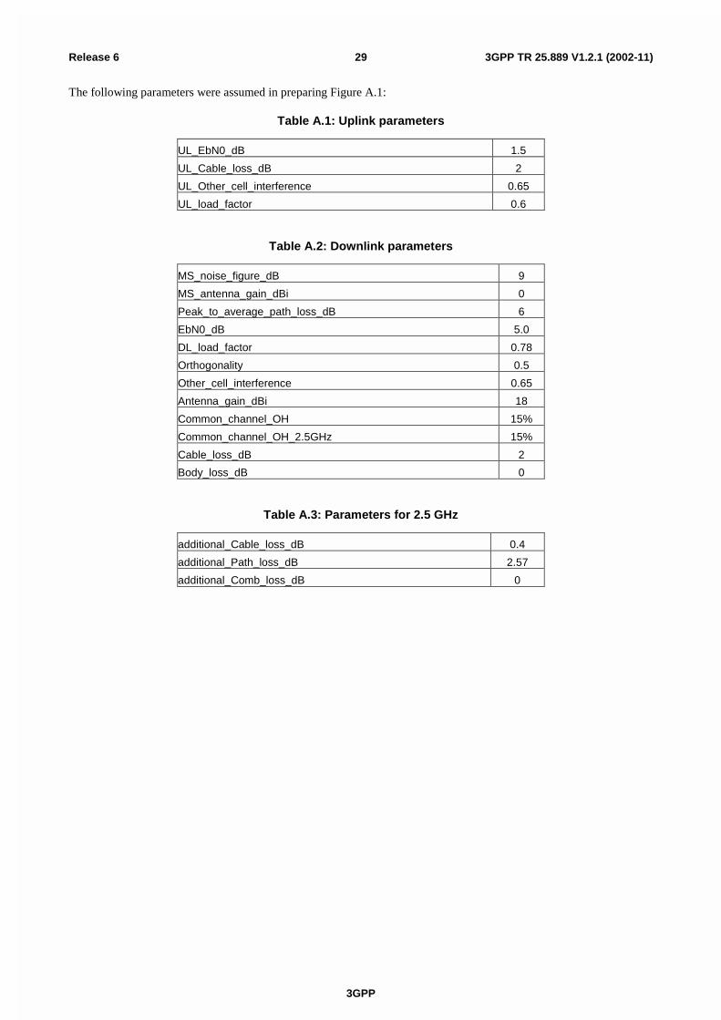
3GPP
3GPP TR 25.889 V1.2.1 (2002-11)29Release 6
The following parameters were assumed in preparing Figure A.1:
Table A.1: Uplink parameters
UL_EbN0_dB 1.5
UL_Cable_loss_dB 2
UL_Other_cell_interference 0.65
UL_load_factor 0.6
Table A.2: Downlink parameters
MS_noise_figure_dB 9
MS_antenna_gain_dBi 0
Peak_to_average_path_loss_dB 6
EbN0_dB 5.0
DL_load_factor 0.78
Orthogonality 0.5
Other_cell_interference 0.65
Antenna_gain_dBi 18
Common_channel_OH 15%
Common_channel_OH_2.5GHz 15%
Cable_loss_dB 2
Body_loss_dB 0
Table A.3: Parameters for 2.5 GHz
additional_Cable_loss_dB 0.4
additional_Path_loss_dB 2.57
additional_Comb_loss_dB 0
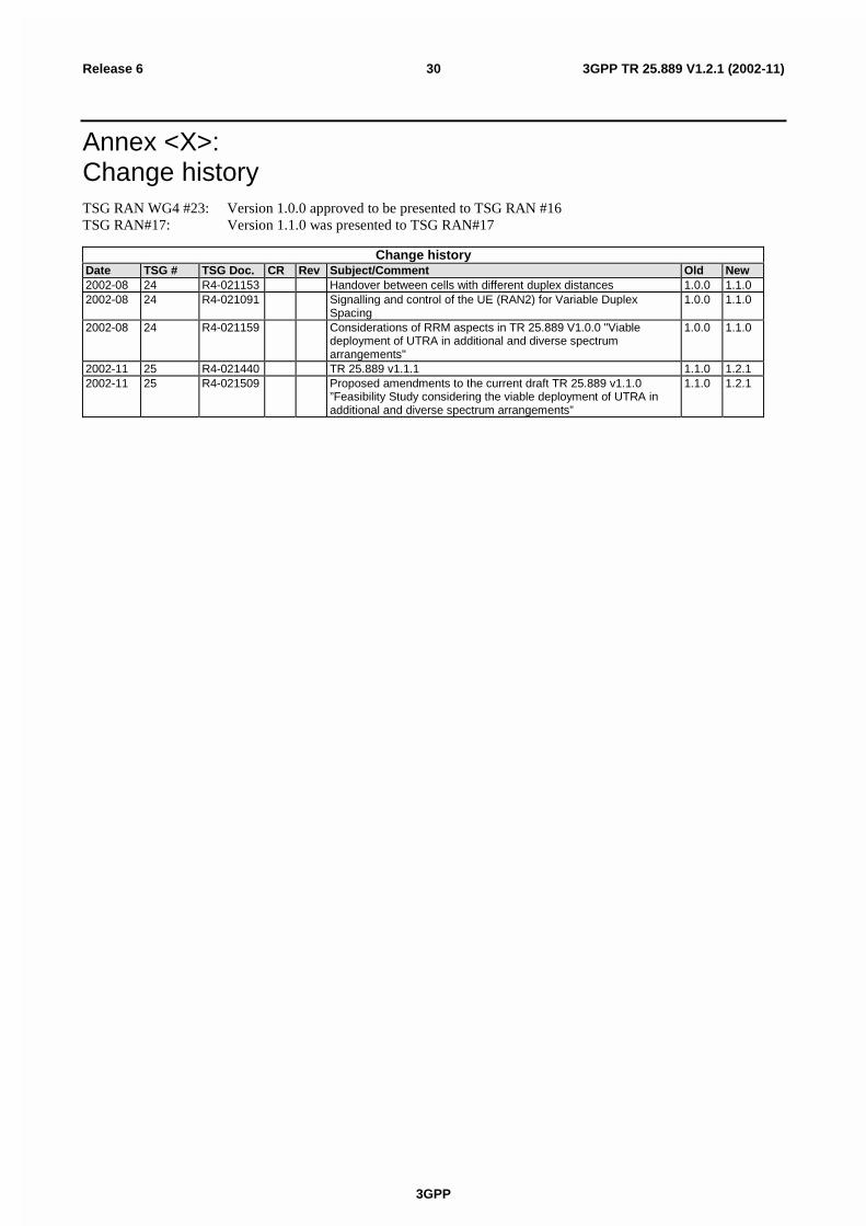
3GPP
3GPP TR 25.889 V1.2.1 (2002-11)30Release 6
Annex <X>:Change historyTSG RAN WG4 #23: Version 1.0.0 approved to be presented to TSG RAN #16TSG RAN#17: Version 1.1.0 was presented to TSG RAN#17
Change historyDate TSG # TSG Doc. CR Rev Subject/Comment Old New2002-08 24 R4-021153 Handover between cells with different duplex distances 1.0.0 1.1.02002-08 24 R4-021091 Signalling and control of the UE (RAN2) for Variable Duplex
Spacing1.0.0 1.1.0
2002-08 24 R4-021159 Considerations of RRM aspects in TR 25.889 V1.0.0 "Viabledeployment of UTRA in additional and diverse spectrumarrangements"
1.0.0 1.1.0
2002-11 25 R4-021440 TR 25.889 v1.1.1 1.1.0 1.2.12002-11 25 R4-021509 Proposed amendments to the current draft TR 25.889 v1.1.0
”Feasibility Study considering the viable deployment of UTRA inadditional and diverse spectrum arrangements”
1.1.0 1.2.1