3GPP-DTAP
460
3GPP TS 24.008 V4.17.0 (2007-09) Technical Specification 3rd Generation Partnership Project; Technical Specification Group Core Network and Terminals; Mobile radio interface Layer 3 specification; Core network protocols; Stage 3 (Release 4) GLOBAL SYSTEM FOR MOBILE COMMUNICATIONS R The present document has been developed within the 3 rd Generation Partnership Project (3GPP TM ) and may be further elaborated for the purposes of 3GPP. The present document has not been subject to any approval process by the 3GPP Organisational Partners and shall not be implemented. This Specification is provided for future development work within 3GPP only. The Organisational Partners accept no liability for any use of this Specification. Specifications and reports for implementation of the 3GPP TM system should be obtained via the 3GPP Organisational Partners' Publications Offices.
-
Upload
khalidox-solitaire -
Category
Documents
-
view
228 -
download
1
description
standard
Transcript of 3GPP-DTAP

3GPP TS 24.008 V4.17.0 (2007-09)Technical Specification
3rd Generation Partnership Project;Technical Specification Group Core Network and Terminals;
Mobile radio interface Layer 3 specification;Core network protocols; Stage 3
(Release 4)
GLOBAL SYSTEM FORMOBILE COMMUNICATIONS
R
The present document has been developed within the 3rd Generation Partnership Project (3GPP TM) and may be further elaborated for the purposes of 3GPP.
The present document has not been subject to any approval process by the 3GPP Organisational Partners and shall not be implemented.This Specification is provided for future development work within 3GPP only. The Organisational Partners accept no liability for any use of this Specification.Specifications and reports for implementation of the 3GPP TM system should be obtained via the 3GPP Organisational Partners' Publications Offices.

3GPP
3GPP TS 24.008 V4.17.0 (2007-09)Release 4 2
KeywordsUMTS, GSM, radio, layer 3, stage 3
3GPP
Postal address
3GPP support office address650 Route des Lucioles - Sophia Antipolis
Valbonne - FRANCETel.: +33 4 92 94 42 00 Fax: +33 4 93 65 47 16
Internethttp://www.3gpp.org
Copyright Notification
No part may be reproduced except as authorized by written permission.The copyright and the foregoing restriction extend to reproduction in all media.
© 2007, 3GPP Organizational Partners (ARIB, ATIS, CCSA, ETSI, TTA, TTC).All rights reserved.

3GPP
3GPP TS 24.008 V4.17.0 (2007-09)Release 4 3
ContentsForeword...........................................................................................................................................................21
Introduction ......................................................................................................................................................21
1 Scope ......................................................................................................................................................221.1 Scope of the Technical Specification............................................................................................................... 221.2 Application to the interface structures ............................................................................................................. 221.3 Structure of layer 3 procedures ........................................................................................................................ 221.4 Test procedures ................................................................................................................................................ 221.5 Use of logical channels in A/Gb mode ............................................................................................................ 231.6 Overview of control procedures....................................................................................................................... 231.6.1 List of procedures....................................................................................................................................... 231.7 Applicability of implementations .................................................................................................................... 251.7.1 Voice Group Call Service (VGCS) and Voice Broadcast Service (VBS) .................................................. 251.7.2 General Packet Radio Service (GPRS)....................................................................................................... 251.7.2.1 Packet services in GSM (GSM only).................................................................................................... 251.7.2.2 Packet services in UMTS (UMTS only)............................................................................................... 26
2 References ..............................................................................................................................................262.1 Definitions and abbreviations .......................................................................................................................... 302.1.1 Random values ........................................................................................................................................... 302.2.2 Vocabulary ................................................................................................................................................. 31
3 Radio Resource management procedures...............................................................................................32
4 Elementary procedures for Mobility Management.................................................................................324.1 General............................................................................................................................................................. 324.1.1 MM and GMM procedures ........................................................................................................................ 334.1.1.1 Types of MM and GMM procedures.................................................................................................... 334.1.1.1.1 Integrity Checking of Signalling Messages in the Mobile Station (UMTS only) ........................... 344.1.1.1.1a Integrity protection for emergency call (UMTS only) .................................................................... 354.1.1.2 MM-GMM co-ordination for GPRS MS's............................................................................................ 364.1.1.2.1 GPRS MS operating in mode A or B in a network that operates in mode I.................................... 364.1.1.2.2 GPRS MS operating in mode A or B in a network that operates in mode II or III ......................... 364.1.1.3 Core Network System Information for MM (UMTS only) .................................................................. 364.1.1.4 Core Network System Information for GMM (UMTS only) ............................................................... 374.1.2 MM sublayer states .................................................................................................................................... 374.1.2.1 MM sublayer states in the mobile station ............................................................................................. 374.1.2.1.1 Main states ...................................................................................................................................... 374.1.2.1.2 Substates of the MM IDLE state..................................................................................................... 414.1.2.2 The update Status ................................................................................................................................. 424.1.2.3 MM sublayer states on the network side .............................................................................................. 434.1.3 GPRS mobility management (GMM) sublayer states ................................................................................ 444.1.3.1 GMM states in the MS.......................................................................................................................... 444.1.3.1.1 Main states ...................................................................................................................................... 444.1.3.1.2 Substates of state GMM-DEREGISTERED................................................................................... 454.1.3.1.3 Substates of state GMM-REGISTERED ........................................................................................ 464.1.3.2 GPRS update status .............................................................................................................................. 484.1.3.3 GMM mobility management states on the network side ...................................................................... 484.1.3.3.1 Main States ..................................................................................................................................... 484.1.3.3.2 Substates of state GMM-REGISTERED ........................................................................................ 494.2 Behaviour of the MS in MM Idle state, GMM-DEREGISTERED state and GMM-REGISTERED state...... 494.2.1 Primary Service State selection.................................................................................................................. 504.2.1.1 Selection of the Service State after Power On. ..................................................................................... 504.2.1.2 Other Cases........................................................................................................................................... 504.2.2 Detailed Description of the MS behaviour in MM IDLE State. ................................................................. 514.2.2.1 Service State, NORMAL SERVICE .................................................................................................... 514.2.2.2 Service State, ATTEMPTING TO UPDATE....................................................................................... 514.2.2.3 Service State, LIMITED SERVICE ..................................................................................................... 52

3GPP
3GPP TS 24.008 V4.17.0 (2007-09)Release 4 4
4.2.2.4 Service State, NO IMSI ........................................................................................................................ 524.2.2.5 Service State, SEARCH FOR PLMN, NORMAL SERVICE .............................................................. 534.2.2.6 Service State, SEARCH FOR PLMN................................................................................................... 534.2.2.7 Service State, RECEIVING GROUP CALL (NORMAL SERVICE).................................................. 534.2.2.8 Service State, RECEIVING GROUP CALL (LIMITED SERVICE) .................................................. 544.2.3 Service state when back to state MM IDLE from another state ................................................................. 544.2.4 Behaviour in state GMM-DEREGISTERED............................................................................................. 554.2.4.1 Primary substate selection .................................................................................................................... 554.2.4.1.1 Selection of the substate after power on or enabling the MS's GPRS capability ............................ 554.2.4.1.2 Other Cases ..................................................................................................................................... 564.2.4.2 Detailed description of the MS behaviour in state GMM-DEREGISTERED ...................................... 564.2.4.2.1 Substate, NORMAL-SERVICE...................................................................................................... 564.2.4.2.2 Substate, ATTEMPTING-TO-ATTACH ....................................................................................... 564.2.4.2.3 Substate, LIMITED-SERVICE....................................................................................................... 564.2.4.2.4 Substate, NO-IMSI ......................................................................................................................... 564.2.4.2.5 Substate, NO-CELL........................................................................................................................ 564.2.4.2.6 Substate, PLMN-SEARCH............................................................................................................. 574.2.4.2.7 Substate, ATTACH-NEEDED........................................................................................................ 574.2.4.2.8 Substate, SUSPENDED (GSM only).............................................................................................. 574.2.4.3 Substate when back to state GMM-DEREGISTERED from another GMM state ............................... 574.2.5 Behaviour in state GMM-REGISTERED .................................................................................................. 574.2.5.1 Detailed description of the MS behaviour in state GMM-REGISTERED ........................................... 584.2.5.1.1 Substate, NORMAL-SERVICE...................................................................................................... 584.2.5.1.2 Substate, SUSPENDED (GSM only).............................................................................................. 584.2.5.1.3 Substate, UPDATE-NEEDED ........................................................................................................ 584.2.5.1.4 Substate, ATTEMPTING-TO-UPDATE........................................................................................ 584.2.5.1.5 Substate, NO-CELL-AVAILABLE................................................................................................ 584.2.5.1.6 Substate, LIMITED-SERVICE....................................................................................................... 594.2.5.1.7 Substate, ATTEMPTING-TO-UPDATE-MM................................................................................ 594.2.5.1.8 Substate, PLMN-SEARCH............................................................................................................. 594.3 MM common procedures................................................................................................................................. 594.3.1 TMSI reallocation procedure...................................................................................................................... 594.3.1.1 TMSI reallocation initiation by the network......................................................................................... 604.3.1.2 TMSI reallocation completion by the mobile station ........................................................................... 604.3.1.3 TMSI reallocation completion in the network. ..................................................................................... 604.3.1.4 Abnormal cases .................................................................................................................................... 604.3.2 Authentication procedure ........................................................................................................................... 614.3.2a Authentication procedure used for a UMTS authentication challenge ................................................. 614.3.2b Authentication Procedure used for a GSM authentication challenge ......................................................... 614.3.2.1 Authentication request by the network ................................................................................................. 624.3.2.2 Authentication response by the mobile station ..................................................................................... 624.3.2.3 Authentication processing in the network ............................................................................................ 624.3.2.4 Ciphering key sequence number........................................................................................................... 634.3.2.5 Authentication not accepted by the network......................................................................................... 634.3.2.5.1 Authentication not accepted by the MS .......................................................................................... 644.3.2.6 Abnormal cases .................................................................................................................................... 644.3.2.6.1 MS behaviour towards a network that has failed the authentication procedure .............................. 664.3.2.7 Handling of keys at intersystem change from UMTS to GSM............................................................. 664.3.2.7a Use of established security contexts ..................................................................................................... 674.3.2.8 Handling of keys at intersystem change from GSM to UMTS............................................................. 674.3.2.9 Void ...................................................................................................................................................... 684.3.3 Identification procedure ............................................................................................................................. 684.3.3.1 Identity request by the network ............................................................................................................ 684.3.3.2 Identification response by the mobile station ....................................................................................... 684.3.3.3 Abnormal cases .................................................................................................................................... 684.3.4 IMSI detach procedure ............................................................................................................................... 694.3.4.1 IMSI detach initiation by the mobile station ........................................................................................ 694.3.4.2 IMSI detach procedure in the network ................................................................................................. 694.3.4.3 IMSI detach completion by the mobile station ..................................................................................... 694.3.4.4 Abnormal cases .................................................................................................................................... 694.3.5 Abort procedure ......................................................................................................................................... 704.3.5.1 Abort procedure initiation by the network............................................................................................ 70

3GPP
3GPP TS 24.008 V4.17.0 (2007-09)Release 4 5
4.3.5.2 Abort procedure in the mobile station .................................................................................................. 704.3.6 MM information procedure ........................................................................................................................ 704.3.6.1 MM information procedure initiation by the network .......................................................................... 704.3.6.2 MM information procedure in the mobile station................................................................................. 704.4 MM specific procedures .................................................................................................................................. 704.4.1 Location updating procedure...................................................................................................................... 714.4.2 Periodic updating ....................................................................................................................................... 724.4.3 IMSI attach procedure................................................................................................................................ 724.4.4 Generic Location Updating procedure ....................................................................................................... 734.4.4.1 Location updating initiation by the mobile station ............................................................................... 734.4.4.1a Network Request for Additional mobile station Capability Information.............................................. 734.4.4.2 Identification request from the network................................................................................................ 734.4.4.3 Authentication by the network.............................................................................................................. 734.4.4.4 Security mode setting by the network................................................................................................... 734.4.4.5 Attempt Counter ................................................................................................................................... 734.4.4.6 Location updating accepted by the network ......................................................................................... 744.4.4.7 Location updating not accepted by the network ................................................................................... 754.4.4.8 Release of RR connection after location updating................................................................................ 764.4.4.9 Abnormal cases on the mobile station side........................................................................................... 764.4.4.10 Abnormal cases on the network side .................................................................................................... 774.4.5 Void............................................................................................................................................................ 784.4.6 Void............................................................................................................................................................ 784.5 Connection management sublayer service provision ....................................................................................... 784.5.1 MM connection establishment ................................................................................................................... 784.5.1.1 MM connection establishment initiated by the mobile station ............................................................. 784.5.1.2 Abnormal cases .................................................................................................................................... 814.5.1.3 MM connection establishment initiated by the network....................................................................... 824.5.1.3.1 Mobile Terminating CM Activity ................................................................................................... 824.5.1.3.2 Mobile Originating CM Activity $(CCBS)$................................................................................... 824.5.1.3.3 Paging response in UMTS (UMTS only)........................................................................................ 834.5.1.4 Abnormal cases .................................................................................................................................... 844.5.1.5 MM connection establishment for emergency calls ............................................................................. 844.5.1.6 Call re-establishment ............................................................................................................................ 844.5.1.6.1 Call re-establishment, initiation by the mobile station.................................................................... 844.5.1.6.2 Abnormal cases............................................................................................................................... 864.5.1.7 Forced release during MO MM connection establishment ................................................................... 874.5.2 MM connection information transfer phase ............................................................................................... 874.5.2.1 Sending CM messages.......................................................................................................................... 874.5.2.2 Receiving CM messages....................................................................................................................... 874.5.2.3 Abnormal cases .................................................................................................................................... 874.5.3 MM connection release .............................................................................................................................. 884.5.3.1 Release of associated RR connection ................................................................................................... 884.5.3.2 Uplink release in a voice group call ..................................................................................................... 884.6 Receiving a MM STATUS message by a MM entity. ..................................................................................... 884.7 Elementary mobility management procedures for GPRS services .................................................................. 894.7.1 General ....................................................................................................................................................... 894.7.1.1 Lower layer failure ............................................................................................................................... 894.7.1.2 Ciphering of messages (GSM only) ..................................................................................................... 894.7.1.3 P-TMSI signature ................................................................................................................................. 894.7.1.4 Radio resource sublayer address handling............................................................................................ 894.7.1.4.1 Radio resource sublayer address handling (GSM only) .................................................................. 904.7.1.5 P-TMSI handling .................................................................................................................................. 904.7.1.5.1 P-TMSI handling in GSM............................................................................................................... 904.7.1.5.2 P-TMSI handling in UMTS ............................................................................................................ 914.7.1.6 Change of network mode of operation ................................................................................................. 914.7.1.6.1 Change of network mode of operation in GSM (GSM only) .......................................................... 914.7.1.6.2 Change of network mode of operation in UMTS (UMTS only) ..................................................... 924.7.1.6.3 Change of network mode of operation at UMTS to GSM inter-system change ............................. 924.7.1.6.4 Change of network mode of operation at GSM to UMTS inter-system change ............................. 934.7.1.7 Intersystem change between GSM and UMTS..................................................................................... 944.7.1.8 List of forbidden PLMNs for GPRS service......................................................................................... 954.7.2 GPRS Mobility management timers and UMTS PS signalling connection control ................................... 95

3GPP
3GPP TS 24.008 V4.17.0 (2007-09)Release 4 6
4.7.2.1 READY timer behaviour ...................................................................................................................... 954.7.2.1.1 READY timer behaviour (GSM only) ............................................................................................ 954.7.2.1.2 Handling of READY timer in UMTS (UMTS only) ...................................................................... 964.7.2.2 Periodic routing area updating.............................................................................................................. 964.7.2.3 PMM-IDLE mode and PMM-CONNECTED mode (UMTS only)...................................................... 974.7.2.4 Handling of Force to standby in UMTS (UMTS only) ........................................................................ 984.7.2.5 RA Update procedure for Signalling Connection Re-establishment (UMTS only).............................. 984.7.3 GPRS attach procedure .............................................................................................................................. 984.7.3.1 GPRS attach procedure for GPRS services .......................................................................................... 994.7.3.1.1 GPRS attach procedure initiation.................................................................................................... 994.7.3.1.2 GMM common procedure initiation ............................................................................................... 994.7.3.1.3 GPRS attach accepted by the network ............................................................................................ 994.7.3.1.4 GPRS attach not accepted by the network .................................................................................... 1004.7.3.1.5 Abnormal cases in the MS ............................................................................................................ 1024.7.3.1.6 Abnormal cases on the network side............................................................................................. 1034.7.3.2 Combined GPRS attach procedure for GPRS and non-GPRS services .............................................. 1054.7.3.2.1 Combined GPRS attach procedure initiation ................................................................................ 1054.7.3.2.2 GMM Common procedure initiation ............................................................................................ 1054.7.3.2.3 Combined GPRS attach accepted by the network......................................................................... 1064.7.3.2.4 Combined GPRS attach not accepted by the network................................................................... 1074.7.3.2.5 Abnormal cases in the MS ............................................................................................................ 1084.7.3.2.6 Abnormal cases on the network side............................................................................................. 1094.7.4 GPRS detach procedure ........................................................................................................................... 1094.7.4.1 MS initiated GPRS detach procedure ................................................................................................. 1094.7.4.1.1 MS initiated GPRS detach procedure initiation ............................................................................ 1094.7.4.1.2 MS initiated GPRS detach procedure completion for GPRS services only .................................. 1104.7.4.1.3 MS initiated combined GPRS detach procedure completion ........................................................ 1104.7.4.1.4 Abnormal cases in the MS ............................................................................................................ 1104.7.4.2 Network initiated GPRS detach procedure ......................................................................................... 1114.7.4.2.1 Network initiated GPRS detach procedure initiation .................................................................... 1114.7.4.2.2 Network initiated GPRS detach procedure completion by the MS ............................................... 1124.7.4.2.3 Network initiated GPRS detach procedure completion by the network........................................ 1144.7.4.2.4 Abnormal cases on the network side............................................................................................. 1144.7.5 Routing area updating procedure ............................................................................................................. 1154.7.5.1 Normal and periodic routing area updating procedure ....................................................................... 1174.7.5.1.1 Normal and periodic routing area updating procedure initiation .................................................. 1174.7.5.1.2 GMM Common procedure initiation ............................................................................................ 1174.7.5.1.3 Normal and periodic routing area updating procedure accepted by the network .......................... 1174.7.5.1.4 Normal and periodic routing area updating procedure not accepted by the network .................... 1194.7.5.1.5 Abnormal cases in the MS ............................................................................................................ 1214.7.5.1.6 Abnormal cases on the network side............................................................................................. 1224.7.5.2 Combined routing area updating procedure........................................................................................ 1234.7.5.2.1 Combined routing area updating procedure initiation................................................................... 1234.7.5.2.2 GMM Common procedure initiation ............................................................................................ 1244.7.5.2.3 Combined routing area updating procedure accepted by the network .......................................... 1244.7.5.2.4 Combined routing area updating not accepted by the network ..................................................... 1264.7.5.2.5 Abnormal cases in the MS ............................................................................................................ 1284.7.5.2.6 Abnormal cases on the network side............................................................................................. 1284.7.6 P-TMSI reallocation procedure ................................................................................................................ 1284.7.6.1 P-TMSI reallocation initiation by the network ................................................................................... 1284.7.6.2 P-TMSI reallocation completion by the MS....................................................................................... 1294.7.6.3 P-TMSI reallocation completion by the network................................................................................ 1294.7.6.4 Abnormal cases on the network side .................................................................................................. 1294.7.7 Authentication and ciphering procedure .................................................................................................. 1304.7.7a Authentication and ciphering procedure used for UMTS authentication challenge. .......................... 1304.7.7b Authentication and ciphering procedure used for GSM authentication challenge.............................. 1314.7.7.1 Authentication and ciphering initiation by the network ..................................................................... 1314.7.7.2 Authentication and ciphering response by the MS ............................................................................. 1324.7.7.3 Authentication and ciphering completion by the network .................................................................. 1334.7.7.4 GPRS ciphering key sequence number............................................................................................... 1334.7.7.5 Authentication not accepted by the network....................................................................................... 1344.7.7.5.1 Authentication not accepted by the MS ........................................................................................ 134
3GPP
3GPP TS 24.008 V4.17.0 (2007-09)Release 4 7
4.7.7.6 Abnormal cases on the network side .................................................................................................. 1354.7.7.6.1 MS behaviour towards a network that has failed the authentication procedure ............................ 1384.7.7.7 Use of established security contexts ................................................................................................... 1384.7.7.8 Handling of keys at intersystem change from UMTS to GSM........................................................... 1394.7.7.9 Handling of keys at intersystem change from GSM to UMTS........................................................... 1394.7.8 Identification procedure ........................................................................................................................... 1394.7.8.1 Identification initiation by the network .............................................................................................. 1404.7.8.2 Identification response by the MS ...................................................................................................... 1404.7.8.3 Identification completion by the network........................................................................................... 1404.7.8.4 Abnormal cases on the network side .................................................................................................. 1404.7.9 Paging procedure...................................................................................................................................... 1414.7.9.1 Paging for GPRS services................................................................................................................... 1414.7.9.1.1 Paging for GPRS services using P-TMSI ..................................................................................... 1414.7.9.1.2 Paging for GPRS services using IMSI .......................................................................................... 1424.7.9.2 Paging for non-GPRS services ........................................................................................................... 1424.7.10 Receiving a GMM STATUS message by a GMM entity......................................................................... 1424.7.11 Void.......................................................................................................................................................... 1424.7.12 GMM Information procedure................................................................................................................... 1424.7.12.1 GMM information procedure initiation by the network ..................................................................... 1434.7.12.2 GMM information procedure in the mobile station ............................................................................ 1434.7.13 Service Request procedure (UMTS only) ................................................................................................ 1434.7.13.1 Service Request procedure initiation .................................................................................................. 1444.7.13.2 GMM common procedure initiation ................................................................................................... 1444.7.13.3 Service request procedure accepted by the network ........................................................................... 1444.7.13.4 Service request procedure not accepted by the network ..................................................................... 1444.7.13.5 Abnormal cases in the MS.................................................................................................................. 1464.7.13.6 Abnormal cases on the network side .................................................................................................. 1474.7.14 Void.......................................................................................................................................................... 148
5 Elementary procedures for circuit-switched Call Control....................................................................1485.1 Overview ....................................................................................................................................................... 1485.1.1 General ..................................................................................................................................................... 1485.1.2 Call Control States ................................................................................................................................... 1525.1.2.1 Call states at the mobile station side of the interface .......................................................................... 1525.1.2.1.1 Null (State U0).............................................................................................................................. 1525.1.2.1.2 MM Connection pending (U0.1)................................................................................................... 1525.1.2.1.2a CC prompt present (U0.2) $(CCBS)$........................................................................................... 1535.1.2.1.2b Wait for network information (U0.3) $(CCBS)$ .......................................................................... 1535.1.2.1.2c CC-Establishment present (U0.4) $(CCBS)$................................................................................ 1535.1.2.1.2d CC-Establishment confirmed (U0.5) $(CCBS)$........................................................................... 1535.1.2.1.2e Recall present (U0.6) $(CCBS)$................................................................................................... 1535.1.2.1.3 Call initiated (U1) ......................................................................................................................... 1535.1.2.1.4 Mobile originating call proceeding (U3)....................................................................................... 1535.1.2.1.5 Call delivered (U4) ....................................................................................................................... 1535.1.2.1.6 Call present (U6)........................................................................................................................... 1535.1.2.1.7 Call received (U7)......................................................................................................................... 1535.1.2.1.8 Connect Request (U8)................................................................................................................... 1535.1.2.1.9 Mobile terminating call confirmed (U9) ....................................................................................... 1545.1.2.1.10 Active (U10) ................................................................................................................................. 1545.1.2.1.11 Disconnect request (U11).............................................................................................................. 1545.1.2.1.12 Disconnect indication (U12) ......................................................................................................... 1545.1.2.1.13 Release request (U19) ................................................................................................................... 1545.1.2.1.14 Mobile originating modify (U26) ................................................................................................. 1545.1.2.1.15 Mobile terminating modify (U27)................................................................................................. 1545.1.2.2 Network call states ............................................................................................................................. 1545.1.2.2.1 Null (State N0).............................................................................................................................. 1545.1.2.2.2 MM connection pending (N0.1).................................................................................................... 1545.1.2.2.2a CC connection pending (N0.2) $(CCBS)$.................................................................................... 1545.1.2.2.2b Network answer pending (N0.3) $(CCBS)$ ................................................................................. 1545.1.2.2.2c CC-Establishment present (N0.4) $(CCBS)$................................................................................ 1555.1.2.2.2d CC-Establishment confirmed (N0.5) $(CCBS)$........................................................................... 1555.1.2.2.3 Call initiated (N1) ......................................................................................................................... 155
3GPP
3GPP TS 24.008 V4.17.0 (2007-09)Release 4 8
5.1.2.2.4 Mobile originating call proceeding (N3)....................................................................................... 1555.1.2.2.5 Call delivered (N4) ....................................................................................................................... 1555.1.2.2.6 Call present (N6)........................................................................................................................... 1555.1.2.2.7 Call received (N7)......................................................................................................................... 1555.1.2.2.8 Connect request (N8) .................................................................................................................... 1555.1.2.2.9 Mobile terminating call confirmed (N9) ....................................................................................... 1555.1.2.2.10 Active (N10) ................................................................................................................................. 1555.1.2.2.11 Not used ........................................................................................................................................ 1555.1.2.2.12 Disconnect indication (N12) ......................................................................................................... 1555.1.2.2.13 Release request (N19) ................................................................................................................... 1565.1.2.2.14 Mobile originating modify (N26) ................................................................................................. 1565.1.2.2.15 Mobile terminating modify (N27)................................................................................................. 1565.1.2.2.16 Connect Indication (N28).............................................................................................................. 1565.2 Call establishment procedures ....................................................................................................................... 1565.2.1 Mobile originating call establishment ...................................................................................................... 1565.2.1.1 Call initiation ...................................................................................................................................... 1575.2.1.2 Receipt of a setup message ................................................................................................................. 1575.2.1.3 Receipt of a CALL PROCEEDING message ..................................................................................... 1595.2.1.4 Notification of progressing mobile originated call ............................................................................. 1595.2.1.4.1 Notification of interworking in connection with mobile originated call establishment ................ 1595.2.1.4.2 Call progress in the PLMN/ISDN environment ............................................................................ 1605.2.1.5 Alerting............................................................................................................................................... 1605.2.1.6 Call connected .................................................................................................................................... 1605.2.1.7 Call rejection ...................................................................................................................................... 1615.2.1.8 Transit network selection.................................................................................................................... 1615.2.1.9 Traffic channel assignment at mobile originating call establishment ................................................. 1615.2.1.10 Call queuing at mobile originating call establishment........................................................................ 1625.2.1.11 Speech Codec Selection...................................................................................................................... 1625.2.2 Mobile terminating call establishment ..................................................................................................... 1635.2.2.1 Call indication .................................................................................................................................... 1635.2.2.2 Compatibility checking....................................................................................................................... 1645.2.2.3 Call confirmation................................................................................................................................ 1645.2.2.3.1 Response to SETUP...................................................................................................................... 1645.2.2.3.2 Receipt of CALL CONFIRMED and ALERTING by the network.............................................. 1645.2.2.3.3 Call failure procedures .................................................................................................................. 1655.2.2.3.4 Called mobile station clearing during mobile terminating call establishment .............................. 1655.2.2.4 Notification of interworking in connection with mobile terminating call establishment.................... 1665.2.2.5 Call accept .......................................................................................................................................... 1665.2.2.6 Active indication ................................................................................................................................ 1665.2.2.7 Traffic channel assignment at mobile terminating call establishment ................................................ 1665.2.2.8 Call queuing at mobile terminating call establishment ....................................................................... 1675.2.2.9 User connection attachment during a mobile terminating call ........................................................... 1675.2.2.10 Speech Codec Selection...................................................................................................................... 1675.2.3 Network initiated MO call $(CCBS)$...................................................................................................... 1675.2.3.1 Initiation ............................................................................................................................................. 1675.2.3.2 CC-Establishment present .................................................................................................................. 1685.2.3.2.1 Recall Alignment Procedure ......................................................................................................... 1695.2.3.3 CC-Establishment confirmation ......................................................................................................... 1705.2.3.4 Recall present ..................................................................................................................................... 1715.2.3.5 Traffic channel assignment during network initiated mobile originating call establishment ............. 1715.3 Signalling procedures during the "active" state ............................................................................................. 1715.3.1 User notification procedure ...................................................................................................................... 1715.3.2 Call rearrangements.................................................................................................................................. 1725.3.3 Codec Change Procedure ......................................................................................................................... 1725.3.4 Support of Dual Services.......................................................................................................................... 1725.3.4.1 Service Description ............................................................................................................................ 1725.3.4.2 Call establishment .............................................................................................................................. 1725.3.4.2.1 Mobile Originating Establishment ................................................................................................ 1725.3.4.2.2 Mobile Terminating Establishment............................................................................................... 1735.3.4.3 Changing the Call Mode..................................................................................................................... 1735.3.4.3.1 Initiation of in-call modification ................................................................................................... 1745.3.4.3.2 Successful completion of in-call modification.............................................................................. 174
3GPP
3GPP TS 24.008 V4.17.0 (2007-09)Release 4 9
5.3.4.3.3 Change of the channel configuration ............................................................................................ 1755.3.4.3.4 Failure of in-call modification ...................................................................................................... 1755.3.4.4 Abnormal procedures ......................................................................................................................... 1755.3.5 User initiated service level up- and downgrading (GSM only) ................................................................ 1765.3.5.1 Initiation of service level up- and downgrading ................................................................................. 1765.3.5.2 Successful completion of service level up- and downgrading............................................................ 1765.3.5.3 Rejection of service level up- and downgrading................................................................................. 1775.3.5.4 Time-out recovery .............................................................................................................................. 1775.3.6 Support of multimedia calls ..................................................................................................................... 1775.3.6.1 Service description ............................................................................................................................. 1775.3.6.2 Call establishment .............................................................................................................................. 1775.3.6.2.1 Mobile originated multimedia call establishment ......................................................................... 1775.3.6.2.2 Mobile terminating multimedia call.............................................................................................. 1785.3.6.3 In-call modification in the "active" state ............................................................................................ 1795.3.6.3.1 Void .............................................................................................................................................. 1795.3.6.3.2 Void .............................................................................................................................................. 1795.3.6.3.3 Void .............................................................................................................................................. 1795.4 Call clearing................................................................................................................................................... 1795.4.1 Terminology............................................................................................................................................. 1795.4.2 Exception conditions ................................................................................................................................ 1795.4.3 Clearing initiated by the mobile station.................................................................................................... 1805.4.3.1 Initiation of call clearing..................................................................................................................... 1805.4.3.2 Receipt of a DISCONNECT message from the mobile station. ......................................................... 1805.4.3.3 Receipt of a RELEASE message from the network ........................................................................... 1805.4.3.4 Receipt of a RELEASE COMPLETE message from the mobile station ............................................ 1805.4.3.5 Abnormal cases .................................................................................................................................. 1805.4.4 Clearing initiated by the network ............................................................................................................. 1815.4.4.1 Clearing initiated by the network: mobile does not support "Prolonged Clearing Procedure" ........... 1815.4.4.1.1 Clearing when tones/announcements provided .................................................................................. 1815.4.4.1.2 Clearing when tones/announcements not provided....................................................................... 1815.4.4.1.3 Completion of clearing ................................................................................................................. 1825.4.4.2 Clearing initiated by the network: mobile supports "Prolonged Clearing Procedure"........................ 1825.4.4.2.1 Clearing when tones/announcements provided and the network does not indicate that "CCBS
activation is possible" ................................................................................................................... 1825.4.4.2.2 Clearing when the network indicates that "CCBS activation is possible" .................................... 1835.4.4.2.3 Clearing when tones/announcements are not provided and the network does not indicate that
"CCBS activation is possible"....................................................................................................... 1845.4.4.2.4 Receipt of a RELEASE message from the mobile station ............................................................ 1855.4.4.2.5 Completion of clearing ................................................................................................................. 1855.5 Miscellaneous procedures.............................................................................................................................. 1865.5.1 In-band tones and announcements ........................................................................................................... 1865.5.2 Call collisions........................................................................................................................................... 1865.5.3 Status procedures ..................................................................................................................................... 1865.5.3.1 Status enquiry procedure .................................................................................................................... 1865.5.3.2 Reception of a STATUS message by a CC entity .............................................................................. 1875.5.3.2.1 STATUS message with incompatible state ................................................................................... 1875.5.3.2.2 STATUS message with compatible state ...................................................................................... 1875.5.4 Call re-establishment, mobile station side................................................................................................ 1875.5.4.1 Indication from the mobility management sublayer ........................................................................... 1875.5.4.2 Reaction of call control....................................................................................................................... 1875.5.4.3 Completion of re-establishment.......................................................................................................... 1875.5.4.4 Unsuccessful outcome ........................................................................................................................ 1885.5.5 Call re-establishment, network side ......................................................................................................... 1885.5.5.1 State alignment ................................................................................................................................... 1885.5.6 Progress.................................................................................................................................................... 1885.5.7 DTMF protocol control procedure ........................................................................................................... 1885.5.7.1 Start DTMF request by the mobile station.......................................................................................... 1885.5.7.2 Start DTMF response by the network................................................................................................. 1895.5.7.3 Stop DTMF request by the mobile station.......................................................................................... 1895.5.7.4 Stop DTMF response by the network ................................................................................................. 1895.5.7.5 Sequencing of subsequent start DTMF requests by the mobile station .............................................. 189

3GPP
3GPP TS 24.008 V4.17.0 (2007-09)Release 4 10
6 Support for packet services ..................................................................................................................1906.1 GPRS Session management........................................................................................................................... 1906.1.1 General ..................................................................................................................................................... 1906.1.2 Session management states ...................................................................................................................... 1906.1.2.1 Session management states in the MS ................................................................................................ 1916.1.2.1.1 PDP-INACTIVE........................................................................................................................... 1916.1.2.1.2 PDP-ACTIVE-PENDING ............................................................................................................ 1916.1.2.1.3 PDP-INACTIVE-PENDING ........................................................................................................ 1916.1.2.1.4 PDP-ACTIVE ............................................................................................................................... 1916.1.2.1.5 PDP-MODIFY_PENDING........................................................................................................... 1916.1.2.2 Session management states on the network side................................................................................. 1926.1.2.2.1 PDP-INACTIVE........................................................................................................................... 1926.1.2.2.2 PDP-ACTIVE-PENDING ............................................................................................................ 1926.1.2.2.3 PDP-INACTIVE-PENDING ........................................................................................................ 1926.1.2.2.4 PDP-ACTIVE ............................................................................................................................... 1926.1.2.2.5 PDP-MODIFY-PENDING ........................................................................................................... 1926.1.3 Session Management procedures ............................................................................................................. 1936.1.3.1 PDP context activation ....................................................................................................................... 1936.1.3.1.1 Successful PDP context activation initiated by the mobile station ............................................... 1936.1.3.1.2 Successful PDP context activation requested by the network....................................................... 1936.1.3.1.3 Unsuccessful PDP context activation initiated by the MS ............................................................ 1946.1.3.1.4 Unsuccessful PDP context activation requested by the network................................................... 1946.1.3.1.5 Abnormal cases............................................................................................................................. 1946.1.3.2 Secondary PDP Context Activation Procedure................................................................................... 1976.1.3.2.1 Successful Secondary PDP Context Activation Procedure Initiated by the MS ........................... 1976.1.3.2.2 Unsuccessful Secondary PDP Context Activation Procedure initiated by the MS ....................... 1986.1.3.2.3 Abnormal cases............................................................................................................................. 1986.1.3.3 PDP context modification procedure.................................................................................................. 1996.1.3.3.1 Network initiated PDP Context Modification ............................................................................... 2006.1.3.3.2 MS initiated PDP Context Modification accepted by the network ............................................... 2006.1.3.3.3 MS initiated PDP Context Modification not accepted by the network ......................................... 2016.1.3.3.4 Abnormal cases............................................................................................................................. 2026.1.3.4 PDP context deactivation procedure................................................................................................... 2036.1.3.4.1 PDP context deactivation initiated by the MS .............................................................................. 2036.1.3.4.2 PDP context deactivation initiated by the network ....................................................................... 2036.1.3.4.3 Abnormal cases............................................................................................................................. 2046.1.3.4a Void .................................................................................................................................................... 2056.1.3.5 Void .................................................................................................................................................... 2056.1.3.6 Receiving a SM STATUS message by a SM entity ........................................................................... 205
7 Examples of structured procedures ......................................................................................................205
8 Handling of unknown, unforeseen, and erroneous protocol data .........................................................2058.1 General........................................................................................................................................................... 2058.2 Message too short .......................................................................................................................................... 2058.3 Unknown or unforeseen transaction identifier ............................................................................................... 2068.3.1 Call Control.............................................................................................................................................. 2068.3.2 Session Management................................................................................................................................ 2078.4 Unknown or unforeseen message type........................................................................................................... 2078.5 Non-semantical mandatory information element errors................................................................................. 2088.5.1 Radio resource management .................................................................................................................... 2088.5.2 Mobility management .............................................................................................................................. 2088.5.3 Call control............................................................................................................................................... 2088.5.4 GMM mobility management .................................................................................................................... 2098.5.5 Session management ................................................................................................................................ 2098.6 Unknown and unforeseen IEs in the non-imperative message part ............................................................... 2098.6.1 IEIs unknown in the message ................................................................................................................... 2098.6.2 Out of sequence IEs.................................................................................................................................. 2098.6.3 Repeated IEs............................................................................................................................................. 2098.7 Non-imperative message part errors .............................................................................................................. 2108.7.1 Syntactically incorrect optional IEs ......................................................................................................... 2108.7.2 Conditional IE errors................................................................................................................................ 210

3GPP
3GPP TS 24.008 V4.17.0 (2007-09)Release 4 11
8.8 Messages with semantically incorrect contents ............................................................................................. 210
9 Message functional definitions and contents........................................................................................2109.1 Messages for Radio Resources management ................................................................................................. 2119.2 Messages for mobility management .............................................................................................................. 2119.2.1 Authentication reject ................................................................................................................................ 2129.2.2 Authentication request.............................................................................................................................. 2139.2.2.1 Authentication Parameter AUTN ....................................................................................................... 2139.2.3 Authentication response ........................................................................................................................... 2139.2.3.1 Authentication Response Parameter ................................................................................................... 2149.2.3.2 Authentication Response Parameter (extension) ................................................................................ 2149.2.3a Authentication Failure.............................................................................................................................. 2149.2.3a.1 Authentication Failure parameter ....................................................................................................... 2149.2.4 CM Re-establishment request .................................................................................................................. 2159.2.4.1 Location area identification ................................................................................................................ 2159.2.4.2 Mobile Station Classmark .................................................................................................................. 2159.2.5 CM service accept .................................................................................................................................... 2159.2.5a CM service prompt $(CCBS)$ ................................................................................................................. 2169.2.6 CM service reject ..................................................................................................................................... 2169.2.7 CM service abort ...................................................................................................................................... 2179.2.8 Abort ........................................................................................................................................................ 2179.2.9 CM service request................................................................................................................................... 2189.2.9.1 Mobile Station Classmark .................................................................................................................. 2189.2.9.2 Priority................................................................................................................................................ 2189.2.10 Identity request......................................................................................................................................... 2189.2.11 Identity response ...................................................................................................................................... 2199.2.12 IMSI detach indication ............................................................................................................................. 2199.2.12.1 Mobile Station Classmark .................................................................................................................. 2209.2.13 Location updating accept ......................................................................................................................... 2209.2.13.1 Follow on proceed .............................................................................................................................. 2209.2.13.2 CTS permission .................................................................................................................................. 2209.2.13.3 Equivalent PLMNs ............................................................................................................................. 2219.2.14 Location updating reject........................................................................................................................... 2219.2.15 Location updating request ........................................................................................................................ 2219.2.15.1 Location area identification ................................................................................................................ 2229.2.15.2 Mobile Station Classmark .................................................................................................................. 2229.2.15.3 Mobile Station Classmark for UMTS................................................................................................. 2229.2.15a MM information....................................................................................................................................... 2229.2.15a.1 Full name for network ........................................................................................................................ 2239.2.15a.2 Short name for network ...................................................................................................................... 2239.2.15a.3 Local time zone .................................................................................................................................. 2239.2.15a.4 Universal time and local time zone .................................................................................................... 2239.2.15a.5 LSA Identity ....................................................................................................................................... 2239.2.15a.6 Network Daylight Saving Time.......................................................................................................... 2249.2.16 MM Status................................................................................................................................................ 2249.2.17 TMSI reallocation command.................................................................................................................... 2249.2.18 TMSI reallocation complete ..................................................................................................................... 2259.2.19 MM Null .................................................................................................................................................. 2259.3 Messages for circuit-switched call control..................................................................................................... 2269.3.1 Alerting .................................................................................................................................................... 2269.3.1.1 Alerting (network to mobile station direction) ................................................................................... 2269.3.1.1.1 Facility .......................................................................................................................................... 2279.3.1.1.2 Progress indicator.......................................................................................................................... 2279.3.1.1.3 User-user ....................................................................................................................................... 2279.3.1.2 Alerting (mobile station to network direction) ................................................................................... 2279.3.1.2.1 Facility .......................................................................................................................................... 2289.3.1.2.2 User-user ....................................................................................................................................... 2289.3.1.2.3 SS version ..................................................................................................................................... 2289.3.2 Call confirmed.......................................................................................................................................... 2289.3.2.1 Repeat indicator.................................................................................................................................. 2289.3.2.2 Bearer capability 1 and bearer capability 2 ........................................................................................ 2299.3.2.3 Cause .................................................................................................................................................. 229
3GPP
3GPP TS 24.008 V4.17.0 (2007-09)Release 4 12
9.3.2.4 CC Capabilities................................................................................................................................... 2299.3.2.5 Stream Identifier ................................................................................................................................. 2299.3.2.6 Supported Codecs............................................................................................................................... 2299.3.3 Call proceeding ........................................................................................................................................ 2299.3.3.1 Repeat indicator.................................................................................................................................. 2309.3.3.2 Bearer capability 1 and bearer capability 2 ........................................................................................ 2309.3.3.3 Facility................................................................................................................................................ 2309.3.3.4 Progress Indicator ............................................................................................................................... 2309.3.3.5 Priority granted ................................................................................................................................... 2309.3.3.6 Network Call Control Capabilities ..................................................................................................... 2309.3.4 Congestion control ................................................................................................................................... 2319.3.4.1 Cause .................................................................................................................................................. 2319.3.5 Connect .................................................................................................................................................... 2319.3.5.1 Connect (network to mobile station direction) ................................................................................... 2319.3.5.1.1 Facility .......................................................................................................................................... 2329.3.5.1.2 Progress indicator.......................................................................................................................... 2329.3.5.1.3 User-user ....................................................................................................................................... 2329.3.5.2 Connect (mobile station to network direction) ................................................................................... 2329.3.5.2.1 Facility .......................................................................................................................................... 2339.3.5.2.2 User-user ....................................................................................................................................... 2339.3.5.2.3 SS version ..................................................................................................................................... 2339.3.5.2.4 Stream Identifier ........................................................................................................................... 2339.3.6 Connect acknowledge .............................................................................................................................. 2339.3.7 Disconnect................................................................................................................................................ 2349.3.7.1 Disconnect (network to mobile station direction)............................................................................... 2349.3.7.1.1 Facility .......................................................................................................................................... 2349.3.7.1.2 Progress indicator.......................................................................................................................... 2349.3.7.1.3 User-user ....................................................................................................................................... 2349.3.7.1.4 Allowed actions $(CCBS)$........................................................................................................... 2349.3.7.2 Disconnect (mobile station to network direction)............................................................................... 2359.3.7.2.1 Facility .......................................................................................................................................... 2359.3.7.2.2 User-user ....................................................................................................................................... 2359.3.7.2.3 SS version ..................................................................................................................................... 2359.3.8 Emergency setup ...................................................................................................................................... 2359.3.8.1 Bearer capability................................................................................................................................. 2369.3.8.2 Stream Identifier ................................................................................................................................. 2369.3.8.3 Supported Codecs............................................................................................................................... 2369.3.8.4 Service category ................................................................................................................................. 2369.3.9 Facility ..................................................................................................................................................... 2369.3.9.1 Facility (network to mobile station direction) .................................................................................... 2369.3.9.2 Facility (mobile station to network direction) .................................................................................... 2379.3.9.2.1 SS version ..................................................................................................................................... 2379.3.10 Hold.......................................................................................................................................................... 2389.3.11 Hold Acknowledge................................................................................................................................... 2389.3.12 Hold Reject............................................................................................................................................... 2389.3.13 Modify...................................................................................................................................................... 2399.3.13.1 Low layer compatibility...................................................................................................................... 2399.3.13.2 High layer compatibility ..................................................................................................................... 2399.3.13.3 Reverse call setup direction ................................................................................................................ 2399.3.13.4 Void .................................................................................................................................................... 2409.3.14 Modify complete ...................................................................................................................................... 2409.3.14.1 Low layer compatibility...................................................................................................................... 2409.3.14.2 High layer compatibility ..................................................................................................................... 2409.3.14.3 Reverse call setup direction ................................................................................................................ 2409.3.15 Modify reject ............................................................................................................................................ 2409.3.15.1 Low layer compatibility...................................................................................................................... 2419.3.15.2 High layer compatibility ..................................................................................................................... 2419.3.16 Notify ....................................................................................................................................................... 2419.3.17 Progress.................................................................................................................................................... 2419.3.17.1 User-user ............................................................................................................................................ 2429.3.17a CC-Establishment $(CCBS)$................................................................................................................... 2429.3.17a.1 Void .................................................................................................................................................... 243
3GPP
3GPP TS 24.008 V4.17.0 (2007-09)Release 4 13
9.3.17a.2 Setup container ................................................................................................................................... 2439.3.17b CC-Establishment confirmed $(CCBS)$ ................................................................................................. 2439.3.17b.1 Repeat indicator.................................................................................................................................. 2439.3.17b.2 Bearer capability 1 and bearer capability 2 ........................................................................................ 2439.3.17b.3 Cause .................................................................................................................................................. 2439.3.17b.4 Supported Codecs............................................................................................................................... 2439.3.18 Release ..................................................................................................................................................... 2449.3.18.1 Release (network to mobile station direction) .................................................................................... 2449.3.18.1.1 Cause............................................................................................................................................. 2449.3.18.1.2 Second cause................................................................................................................................. 2449.3.18.1.3 Facility .......................................................................................................................................... 2449.3.18.1.4 User-user ....................................................................................................................................... 2449.3.18.2 Release (mobile station to network direction) .................................................................................... 2449.3.18.2.1 Cause............................................................................................................................................. 2459.3.18.2.2 Second cause................................................................................................................................. 2459.3.18.2.3 Facility .......................................................................................................................................... 2459.3.18.2.4 User-user ....................................................................................................................................... 2459.3.18.2.5 SS version ..................................................................................................................................... 2459.3.18a Recall $(CCBS)$...................................................................................................................................... 2459.3.18a.1 Recall Type......................................................................................................................................... 2469.3.18a.2 Facility................................................................................................................................................ 2469.3.19 Release complete...................................................................................................................................... 2469.3.19.1 Release complete (network to mobile station direction)..................................................................... 2469.3.19.1.1 Cause............................................................................................................................................. 2479.3.19.1.2 Facility .......................................................................................................................................... 2479.3.19.1.3 User-user ....................................................................................................................................... 2479.3.19.2 Release complete (mobile station to network direction)..................................................................... 2479.3.19.2.1 Cause............................................................................................................................................. 2489.3.19.2.2 Facility .......................................................................................................................................... 2489.3.19.2.3 User-user ....................................................................................................................................... 2489.3.19.2.4 SS version. .................................................................................................................................... 2489.3.20 Retrieve .................................................................................................................................................... 2489.3.21 Retrieve Acknowledge ............................................................................................................................. 2499.3.22 Retrieve Reject ......................................................................................................................................... 2499.3.23 Setup......................................................................................................................................................... 2509.3.23.1 Setup (mobile terminated call establishment)..................................................................................... 2509.3.23.1.1 BC repeat indicator ....................................................................................................................... 2519.3.23.1.2 Bearer capability 1 and bearer capability 2 ................................................................................... 2529.3.23.1.3 Facility .......................................................................................................................................... 2529.3.23.1.4 Progress indicator.......................................................................................................................... 2529.3.23.1.4a Called party BCD number............................................................................................................. 2529.3.23.1.5 Called party subaddress ................................................................................................................ 2529.3.23.1.6 LLC repeat indicator ..................................................................................................................... 2529.3.23.1.7 Low layer compatibility I.............................................................................................................. 2529.3.23.1.8 Low layer compatibility II ............................................................................................................ 2529.3.23.1.9 HLC repeat indicator..................................................................................................................... 2529.3.23.1.10 High layer compatibility i ............................................................................................................. 2529.3.23.1.11 High layer compatibility ii ............................................................................................................ 2539.3.23.1.12 User-user ....................................................................................................................................... 2539.3.23.1.13 Redirecting party BCD number .................................................................................................... 2539.3.23.1.14 Redirecting party subaddress ........................................................................................................ 2539.3.23.1.15 Priority .......................................................................................................................................... 2539.3.23.1.16 Alert $(Network Indication of Alerting in the MS)$ .................................................................... 2539.3.23.1.17 Network Call Control Capabilities................................................................................................ 2539.3.23.1.18 Cause of No CLI ........................................................................................................................... 2539.3.23.2 Setup (mobile originating call establishment) .................................................................................... 2539.3.23.2.1 BC repeat indicator ....................................................................................................................... 2549.3.23.2.2 Facility .......................................................................................................................................... 2549.3.23.2.3 LLC repeat indicator ..................................................................................................................... 2559.3.23.2.4 Low layer compatibility I.............................................................................................................. 2559.3.23.2.5 Low layer compatibility II ............................................................................................................ 2559.3.23.2.6 HLC repeat indicator..................................................................................................................... 255
3GPP
3GPP TS 24.008 V4.17.0 (2007-09)Release 4 14
9.3.23.2.7 High layer compatibility i ............................................................................................................. 2559.3.23.2.8 High layer compatibility ii ............................................................................................................ 2559.3.23.2.9 User-user ....................................................................................................................................... 2559.3.23.2.10 SS version ..................................................................................................................................... 2559.3.23.2.11 CLIR suppression.......................................................................................................................... 2559.3.23.2.12 CLIR invocation............................................................................................................................ 2559.3.23.2.13 CC Capabilities ............................................................................................................................. 2569.3.23.2.14 Stream Identifier ........................................................................................................................... 2569.3.23.2.15 Bearer capability 1 and bearer capability 2 ................................................................................... 2569.3.23.2.16 Supported Codecs ......................................................................................................................... 2569.3.23a Start CC $(CCBS)$ .................................................................................................................................. 2569.3.23a.1 CC Capabilities................................................................................................................................... 2569.3.24 Start DTMF .............................................................................................................................................. 2569.3.25 Start DTMF Acknowledge ....................................................................................................................... 2579.3.25.1 Keypad facility ................................................................................................................................... 2579.3.26 Start DTMF reject .................................................................................................................................... 2579.3.27 Status........................................................................................................................................................ 2589.3.27.1 Auxiliary states ................................................................................................................................... 2589.3.28 Status enquiry........................................................................................................................................... 2589.3.29 Stop DTMF .............................................................................................................................................. 2599.3.30 Stop DTMF acknowledge ........................................................................................................................ 2599.3.31 User information ...................................................................................................................................... 2599.3.31.1 User-user ............................................................................................................................................ 2609.3.31.2 More data............................................................................................................................................ 2609.4 GPRS Mobility Management Messages ........................................................................................................ 2609.4.1 Attach request........................................................................................................................................... 2609.4.1.1 Old P-TMSI signature ........................................................................................................................ 2619.4.1.2 Requested READY timer value.......................................................................................................... 2619.4.1.3 TMSI status ........................................................................................................................................ 2619.4.2 Attach accept ............................................................................................................................................ 2619.4.2.1 P-TMSI signature ............................................................................................................................... 2629.4.2.2 Negotiated READY timer .................................................................................................................. 2629.4.2.3 Allocated P-TMSI .............................................................................................................................. 2629.4.2.4 MS identity ......................................................................................................................................... 2629.4.2.5 GMM cause ........................................................................................................................................ 2629.4.2.6 T3302 value ........................................................................................................................................ 2639.4.2.7 Cell Notification (GSM only) ............................................................................................................. 2639.4.2.8 Equivalent PLMNs ............................................................................................................................. 2639.4.2.9 Network feature support ..................................................................................................................... 2639.4.3 Attach complete ....................................................................................................................................... 2639.4.4 Attach reject ............................................................................................................................................. 2639.4.4.1 T3302 value ........................................................................................................................................ 2649.4.5 Detach request .......................................................................................................................................... 2649.4.5.1 Detach request (mobile terminated detach) ........................................................................................ 2649.4.5.1.1 GMM cause ........................................................................................................................................ 2649.4.5.2 Detach request (mobile originating detach) ........................................................................................ 2649.4.5.2.1 P-TMSI ......................................................................................................................................... 2659.4.5.2.2 P-TMSI signature.......................................................................................................................... 2659.4.6 Detach accept ........................................................................................................................................... 2659.4.6.1 Detach accept (mobile terminated detach).......................................................................................... 2659.4.6.2 Detach accept (mobile originating detach) ......................................................................................... 2659.4.7 P-TMSI reallocation command ................................................................................................................ 2669.4.7.1 P-TMSI signature ............................................................................................................................... 2669.4.8 P-TMSI reallocation complete ................................................................................................................. 2669.4.9 Authentication and ciphering request ....................................................................................................... 2679.4.9.1 Authentication Parameter RAND ....................................................................................................... 2679.4.9.2 GPRS ciphering key sequence number............................................................................................... 2679.4.9.3 Authentication Parameter AUTN ....................................................................................................... 2679.4.10 Authentication and ciphering response .................................................................................................... 2689.4.10.1 Authentication Response Parameter ................................................................................................... 2689.4.10.2 IMEISV .............................................................................................................................................. 2689.4.10.3 Authentication Response Parameter (extension) ................................................................................ 268
3GPP
3GPP TS 24.008 V4.17.0 (2007-09)Release 4 15
9.4.10a Authentication and Ciphering Failure ...................................................................................................... 2689.4.10a.1 Authentication Failure parameter ....................................................................................................... 2699.4.11 Authentication and ciphering reject ......................................................................................................... 2699.4.12 Identity request......................................................................................................................................... 2699.4.13 Identity response ...................................................................................................................................... 2709.4.14 Routing area update request ..................................................................................................................... 2709.4.14.1 Old P-TMSI signature ........................................................................................................................ 2719.4.14.2 Requested READY timer value.......................................................................................................... 2719.4.14.3 DRX parameter................................................................................................................................... 2719.4.14.4 TMSI status ........................................................................................................................................ 2719.4.14.5 P-TMSI (UMTS only) ........................................................................................................................ 2719.4.14.6 MS network capability........................................................................................................................ 2719.4.14.7 PDP context status .............................................................................................................................. 2729.4.15 Routing area update accept ...................................................................................................................... 2729.4.15.1 P-TMSI signature ............................................................................................................................... 2729.4.15.2 Allocated P-TMSI .............................................................................................................................. 2729.4.15.3 MS identity ......................................................................................................................................... 2739.4.15.4 List of Receive N-PDU Numbers ....................................................................................................... 2739.4.15.5 Negotiated READY timer value ......................................................................................................... 2739.4.15.6 GMM cause ........................................................................................................................................ 2739.4.15.7 T3302 value ........................................................................................................................................ 2739.4.15.8 Cell Notification (GSM only) ............................................................................................................. 2739.4.15.9 Equivalent PLMNs ............................................................................................................................. 2739.4.15.10 PDP context status .............................................................................................................................. 2739.4.15.11 Network feature support ..................................................................................................................... 2739.4.16 Routing area update complete .................................................................................................................. 2739.4.16.1 List of Receive N-PDU Numbers ....................................................................................................... 2749.4.17 Routing area update reject........................................................................................................................ 2749.4.17.1 T3302 value ........................................................................................................................................ 2749.4.18 GMM Status ............................................................................................................................................. 2749.4.19 GMM Information.................................................................................................................................... 2759.4.19.1 Full name for network ........................................................................................................................ 2759.4.19.2 Short name for network ...................................................................................................................... 2759.4.19.3 Local time zone .................................................................................................................................. 2759.4.19.4 Universal time and local time zone .................................................................................................... 2769.4.19.5 LSA Identity ....................................................................................................................................... 2769.4.19.6 Network Daylight Saving Time.......................................................................................................... 2769.4.20 Service Request (UMTS only) ................................................................................................................. 2769.4.20.1 PDP context status .............................................................................................................................. 2769.4.21 Service Accept (UMTS only)................................................................................................................... 2769.4.21.1 PDP context status .............................................................................................................................. 2779.4.22 Service Reject (UMTS only) .................................................................................................................... 2779.5 GPRS Session Management Messages .......................................................................................................... 2779.5.1 Activate PDP context request................................................................................................................... 2779.5.1.1 Access point name .............................................................................................................................. 2789.5.1.2 Protocol configuration options ........................................................................................................... 2789.5.2 Activate PDP context accept .................................................................................................................... 2789.5.2.1 PDP address........................................................................................................................................ 2799.5.2.2 Protocol configuration options ........................................................................................................... 2799.5.2.3 Packet Flow Identifier ........................................................................................................................ 2799.5.3 Activate PDP context reject ..................................................................................................................... 2799.5.3.1 Protocol configuration options ........................................................................................................... 2809.5.4 Activate Secondary PDP Context Request............................................................................................... 2809.5.4.1 TFT..................................................................................................................................................... 2809.5.5 Activate Secondary PDP Context Accept ................................................................................................ 2819.5.5.1 Packet Flow Identifier ........................................................................................................................ 2819.5.6 Activate Secondary PDP Context Reject ................................................................................................. 2819.5.7 Request PDP context activation ............................................................................................................... 2829.5.8 Request PDP context activation reject ..................................................................................................... 2829.5.9 Modify PDP context request (Network to MS direction)......................................................................... 2829.5.9.1 PDP address........................................................................................................................................ 2839.5.9.2 Packet Flow Identifier ........................................................................................................................ 283
3GPP
3GPP TS 24.008 V4.17.0 (2007-09)Release 4 16
9.5.10 Modify PDP context request (MS to network direction).......................................................................... 2839.5.10.1 Requested LLC SAPI ......................................................................................................................... 2849.5.10.2 Requested new QoS............................................................................................................................ 2849.5.10.3 New TFT ............................................................................................................................................ 2849.5.11 Modify PDP context accept (MS to network direction) ........................................................................... 2849.5.12 Modify PDP context accept (Network to MS direction) .......................................................................... 2849.5.12.1 Negotiated QoS .................................................................................................................................. 2859.5.12.2 Negotiated LLC SAPI ........................................................................................................................ 2859.5.12.3 New radio priority .............................................................................................................................. 2859.5.12.4 Packet Flow Identifier ........................................................................................................................ 2859.5.13 Modify PDP Context Reject..................................................................................................................... 2859.5.14 Deactivate PDP context request ............................................................................................................... 2869.5.14.1 Tear down indicator............................................................................................................................ 2869.5.15 Deactivate PDP context accept................................................................................................................. 2869.5.16 Void.......................................................................................................................................................... 2879.5.17 Void.......................................................................................................................................................... 2879.5.18 Void.......................................................................................................................................................... 2879.5.19 Void.......................................................................................................................................................... 2879.5.20 Void.......................................................................................................................................................... 2879.5.21 SM Status ................................................................................................................................................. 287
10 General message format and information elements coding .................................................................28710.1 Overview ....................................................................................................................................................... 28710.2 Protocol Discriminator................................................................................................................................... 28810.3 Skip indicator and transaction identifier ........................................................................................................ 28810.3.1 Skip indicator ........................................................................................................................................... 28810.3.2 Transaction identifier ............................................................................................................................... 28810.4 Message Type ................................................................................................................................................ 28910.5 Other information elements ........................................................................................................................... 29210.5.1 Common information elements. ............................................................................................................... 29310.5.1.1 Cell identity ........................................................................................................................................ 29310.5.1.2 Ciphering Key Sequence Number ...................................................................................................... 29410.5.1.3 Location Area Identification............................................................................................................... 29410.5.1.4 Mobile Identity ................................................................................................................................... 29610.5.1.5 Mobile Station Classmark 1 ............................................................................................................... 29810.5.1.6 Mobile Station Classmark 2 ............................................................................................................... 30010.5.1.7 Mobile Station Classmark 3 ............................................................................................................... 30310.5.1.8 Spare Half Octet ................................................................................................................................. 31110.5.1.9 Descriptive group or broadcast call reference .................................................................................... 31110.5.1.10 Group Cipher Key Number ................................................................................................................ 31310.5.1.10a PD and SAPI $(CCBS)$..................................................................................................................... 31410.5.1.11 Priority Level...................................................................................................................................... 31510.5.1.12 Core Network System Information (UMTS only) .............................................................................. 31510.5.1.12.1 CN Common GSM-MAP NAS system information..................................................................... 31510.5.1.12.2 CS domain specific system information ....................................................................................... 31610.5.1.12.3 PS domain specific system information ........................................................................................ 31610.5.1.13 PLMN list ........................................................................................................................................... 31710.5.2 Radio Resource management information elements. ............................................................................... 31810.5.3 Mobility management information elements............................................................................................ 31810.5.3.1 Authentication parameter RAND ....................................................................................................... 31810.5.3.1.1 Authentication Parameter AUTN (UMTS authentication challenge only) ................................... 31810.5.3.2 Authentication Response parameter ................................................................................................... 31910.5.3.2.1 Authentication Response Parameter (extension) (UMTS authentication challenge only) ............ 32010.5.3.2.2 Authentication Failure parameter (UMTS authentication challenge only) ................................... 32010.5.3.3 CM service type.................................................................................................................................. 32110.5.3.4 Identity type........................................................................................................................................ 32110.5.3.5 Location updating type ....................................................................................................................... 32210.5.3.5a Network Name.................................................................................................................................... 32210.5.3.6 Reject cause ........................................................................................................................................ 32310.5.3.7 Follow-on Proceed.............................................................................................................................. 32410.5.3.8 Time Zone .......................................................................................................................................... 32510.5.3.9 Time Zone and Time .......................................................................................................................... 325
3GPP
3GPP TS 24.008 V4.17.0 (2007-09)Release 4 17
10.5.3.10 CTS permission .................................................................................................................................. 32610.5.3.11 LSA Identifier..................................................................................................................................... 32710.5.3.12 Daylight Saving Time......................................................................................................................... 32710.5.4 Call control information elements ............................................................................................................ 32810.5.4.1 Extensions of codesets........................................................................................................................ 32810.5.4.2 Locking shift procedure...................................................................................................................... 32810.5.4.3 Non-locking shift procedure ............................................................................................................... 32910.5.4.4 Auxiliary states ................................................................................................................................... 32910.5.4.5 Bearer capability................................................................................................................................. 33010.5.4.5.1 Static conditions for the bearer capability IE contents.................................................................. 34510.5.4.5a Call Control Capabilities .................................................................................................................... 34510.5.4.6 Call state ............................................................................................................................................. 34610.5.4.7 Called party BCD number .................................................................................................................. 34710.5.4.8 Called party subaddress ...................................................................................................................... 34910.5.4.9 Calling party BCD number ................................................................................................................. 35010.5.4.10 Calling party subaddress..................................................................................................................... 35110.5.4.11 Cause .................................................................................................................................................. 35210.5.4.11a CLIR suppression ............................................................................................................................... 35710.5.4.11b CLIR invocation ................................................................................................................................. 35810.5.4.12 Congestion level ................................................................................................................................. 35810.5.4.13 Connected number.............................................................................................................................. 35810.5.4.14 Connected subaddress......................................................................................................................... 35910.5.4.15 Facility................................................................................................................................................ 35910.5.4.16 High layer compatibility ..................................................................................................................... 36010.5.4.16.1 Static conditions for the high layer compatibility IE contents ...................................................... 36010.5.4.17 Keypad facility ................................................................................................................................... 36010.5.4.18 Low layer compatibility...................................................................................................................... 36110.5.4.19 More data............................................................................................................................................ 36110.5.4.20 Notification indicator.......................................................................................................................... 36210.5.4.21 Progress indicator ............................................................................................................................... 36210.5.4.21a Recall type $(CCBS)$................................................................................................................... 36310.5.4.21b Redirecting party BCD number .................................................................................................... 36410.5.4.21c Redirecting party subaddress ........................................................................................................ 36410.5.4.22 Repeat indicator.................................................................................................................................. 36510.5.4.22a Reverse call setup direction ................................................................................................................ 36510.5.4.22b SETUP Container $(CCBS)$ ............................................................................................................. 36610.5.4.23 Signal.................................................................................................................................................. 36610.5.4.24 SS Version Indicator........................................................................................................................... 36710.5.4.25 User-user ............................................................................................................................................ 36710.5.4.26 Alerting Pattern $(NIA)$.................................................................................................................... 36810.5.4.27 Allowed actions $(CCBS)$ ................................................................................................................ 36910.5.4.28 Stream Identifier ................................................................................................................................. 36910.5.4.29 Network Call Control Capabilities ..................................................................................................... 37010.5.4.30 Cause of No CLI................................................................................................................................. 37010.5.4.31 Void .................................................................................................................................................... 37110.5.4.32 Supported codec list............................................................................................................................ 37110.5.4.33 Service category ................................................................................................................................. 37210.5.5 GPRS mobility management information elements ................................................................................. 37310.5.5.1 Attach result........................................................................................................................................ 37310.5.5.2 Attach type.......................................................................................................................................... 37310.5.5.3 Ciphering algorithm............................................................................................................................ 37410.5.5.4 TMSI status ........................................................................................................................................ 37410.5.5.5 Detach type ......................................................................................................................................... 37510.5.5.6 DRX parameter................................................................................................................................... 37610.5.5.7 Force to standby ................................................................................................................................. 37810.5.5.8 P-TMSI signature ............................................................................................................................... 37810.5.5.8a P-TMSI signature 2 ............................................................................................................................ 37910.5.5.9 Identity type 2..................................................................................................................................... 37910.5.5.10 IMEISV request.................................................................................................................................. 38010.5.5.11 Receive N-PDU Numbers list............................................................................................................. 38010.5.5.12 MS network capability........................................................................................................................ 38110.5.5.12a MS Radio Access capability............................................................................................................... 383
3GPP
3GPP TS 24.008 V4.17.0 (2007-09)Release 4 18
10.5.5.13 Spare................................................................................................................................................... 38910.5.5.14 GMM cause ........................................................................................................................................ 38910.5.5.15 Routing area identification ................................................................................................................. 39010.5.5.16 Spare................................................................................................................................................... 39210.5.5.17 Update result....................................................................................................................................... 39210.5.5.18 Update type......................................................................................................................................... 39210.5.5.19 A&C reference number ...................................................................................................................... 39310.5.5.20 Service type ........................................................................................................................................ 39310.5.5.21 Cell Notification ................................................................................................................................. 39410.5.5.22 Spare................................................................................................................................................... 39410.5.5.23 Network feature support ..................................................................................................................... 39410.5.6 Session management information elements ............................................................................................. 39510.5.6.1 Access Point Name............................................................................................................................. 39510.5.6.2 Network service access point identifier .............................................................................................. 39510.5.6.3 Protocol configuration options ........................................................................................................... 39610.5.6.4 Packet data protocol address............................................................................................................... 39910.5.6.5 Quality of service ............................................................................................................................... 40010.5.6.6 SM cause ............................................................................................................................................ 40610.5.6.7 Linked TI ............................................................................................................................................ 40710.5.6.8 Spare................................................................................................................................................... 40810.5.6.9 LLC service access point identifier .................................................................................................... 40810.5.6.10 Tear down indicator............................................................................................................................ 40810.5.6.11 Packet Flow Identifier ........................................................................................................................ 40910.5.6.12 Traffic Flow Template........................................................................................................................ 40910.5.7 GPRS Common information elements ..................................................................................................... 41310.5.7.1 PDP context status .............................................................................................................................. 41310.5.7.2 Radio priority...................................................................................................................................... 41310.5.7.3 GPRS Timer ....................................................................................................................................... 41410.5.7.4 GPRS Timer 2 .................................................................................................................................... 414
11 List of system parameters.....................................................................................................................41611.1 Timers and counters for radio resource management .................................................................................... 41611.2 Timers of mobility management .................................................................................................................... 41611.2.1 Timer T3240 and Timer T3241................................................................................................................ 41711.2.2 Timers of GPRS mobility management ................................................................................................... 41811.2.3 Timers of session management ................................................................................................................ 42111.3 Timers of circuit-switched call control .......................................................................................................... 422
Annex A (informative): Example of subaddress information element coding................................424
Annex B (normative): Compatibility checking ...............................................................................425B.1 Introduction ..........................................................................................................................................425
B.2 Calling side compatibility checking .....................................................................................................425B.2.1 Compatibility checking of the CM SERVICE REQUEST message.............................................................. 425B.2.2 Compatibility/Subscription checking of the SETUP message ....................................................................... 425
B.3 Called side compatibility checking ......................................................................................................425B.3.1 Compatibility checking with addressing information .................................................................................... 426B.3.2 Network-to-MS compatibility checking ........................................................................................................ 426B.3.3 User-to-User compatibility checking ............................................................................................................. 426
B.4 High layer compatibility checking .......................................................................................................426
Annex C (normative): Low layer information coding principles...................................................427C.1 Purpose.................................................................................................................................................427
C.2 Principles..............................................................................................................................................427C.2.1 Definition of types of information ................................................................................................................. 427C.2.2 Examination by network ................................................................................................................................ 427C.2.3 Location of type I information....................................................................................................................... 428C.2.4 Location of types II and III information ........................................................................................................ 428C.2.5 Relationship between bearer capability and low layer compatibility information elements .......................... 428
3GPP
3GPP TS 24.008 V4.17.0 (2007-09)Release 4 19
Annex D (informative): Examples of bearer capability information element coding ....................429D.1 Coding for speech for a full rate support only mobile station..............................................................429D.1.1 Mobile station to network direction ............................................................................................................... 429D.1.2 Network to mobile station direction .............................................................................................................. 429
D.2 An example of a coding for modem access with V22-bis, 2,4 kbit/s, 8 bit no parity ..........................430D.2.1 Mobile station to network direction, data compression allowed.................................................................... 430D.2.2 Network to mobile station direction, data compression possible ................................................................... 431
D.3 An example of a coding for group 3 facsimile (9,6 kbit/s, transparent)...............................................432D.3.1 Mobile station to network direction ............................................................................................................... 432D.3.2 Network to mobile station direction .............................................................................................................. 433
Annex E (informative): Comparison between call control procedures specified in 3GPP TS24.008 and ITU-T Recommendation Q.931...............................................434
Annex F (informative): GSM specific cause values for radio resource management ....................438
Annex G (informative): UMTS specific cause values for mobility management ............................439G.1 Causes related to MS identification......................................................................................................439
G.2 Cause related to subscription options...................................................................................................439
G.3 Causes related to PLMN specific network failures and congestion/Authentication Failures ..............440
G.4 Causes related to nature of request.......................................................................................................440
G.5 Causes related to invalid messages ......................................................................................................440
G.6 Additional cause codes for GMM ........................................................................................................441
Annex H (informative): UMTS specific cause values for call control ..............................................442
H.1 Normal class.........................................................................................................................................442H.1.1 Cause No. 1 "unassigned (unallocated) number"........................................................................................... 442H.1.2 Cause No. 3 "no route to destination"............................................................................................................ 442H.1.3 Cause No. 6 "channel unacceptable" ............................................................................................................. 442H.1.4 Cause No. 8 "operator determined barring" ................................................................................................... 442H.1.5 Cause No.16 "normal call clearing"............................................................................................................... 442H.1.6 Cause No.17 "user busy" ............................................................................................................................... 442H.1.7 Cause No. 18 "no user responding" ............................................................................................................... 442H.1.8 Cause No. 19 "user alerting, no answer" ....................................................................................................... 442H.1.9 Cause No. 21 "call rejected" .......................................................................................................................... 443H.1.10 Cause No. 22 "number changed" ................................................................................................................... 443H.1.11 Cause No. 25 "pre-emption" .......................................................................................................................... 443H.1.12 Cause No. 26 "non-selected user clearing" .................................................................................................... 443H.1.13 Cause No. 27 "destination out of order" ........................................................................................................ 443H.1.14 Cause No. 28 "invalid number format (incomplete number)" ....................................................................... 443H.1.15 Cause No. 29 "facility rejected"..................................................................................................................... 443H.1.16 Cause No. 30 "response to STATUS ENQUIRY"......................................................................................... 443H.1.17 Cause No. 31 "normal, unspecified" .............................................................................................................. 443
H.2 Resource unavailable class...................................................................................................................443H.2.1 Cause No. 34 "no circuit/channel available".................................................................................................. 443H.2.2 Cause No. 38 "network out of order"............................................................................................................. 444H.2.3 Cause No. 41 "temporary failure".................................................................................................................. 444H.2.4 Cause No. 42 "switching equipment congestion" .......................................................................................... 444H.2.5 Cause No. 43 "access information discarded" ............................................................................................... 444H.2.6 Cause No. 44 "requested circuit/channel not available" ................................................................................ 444H.2.7 Cause No. 47 "resource unavailable, unspecified" ........................................................................................ 444
H.3 Service or option not available class ....................................................................................................444H.3.1 Cause No. 49 "quality of service unavailable"............................................................................................... 444H.3.2 Cause No. 50 "Requested facility not subscribed"......................................................................................... 444

3GPP
3GPP TS 24.008 V4.17.0 (2007-09)Release 4 20
H.3.3 Cause No. 55 "Incoming calls barred within the CUG" ................................................................................ 444H.3.4 Cause No. 57 "bearer capability not authorized" ........................................................................................... 445H.3.5 Cause No. 58 "bearer capability not presently available" .............................................................................. 445H.3.6 Cause No. 63 "service or option not available, unspecified" ......................................................................... 445H.3.7 Cause No. 68 "ACM equal to or greater than ACMmax".............................................................................. 445
H.4 Service or option not implemented class..............................................................................................445H.4.1 Cause No. 65 "bearer service not implemented"............................................................................................ 445H.4.2 Cause No. 69 "Requested facility not implemented" ..................................................................................... 445H.4.3 Cause No. 70 "only restricted digital information bearer capability is available" ......................................... 445H.4.4 Cause No. 79 "service or option not implemented, unspecified"................................................................... 445
H.5 Invalid message (e.g., parameter out of range) class............................................................................445H.5.1 Cause No. 81 "invalid transaction identifier value" ....................................................................................... 445H.5.2 Cause No. 87 "user not member of CUG" ..................................................................................................... 446H.5.3 Cause No. 88 "incompatible destination" ...................................................................................................... 446H.5.4 Cause No. 91 "invalid transit network selection" .......................................................................................... 446H.5.5 Cause No. 95 "semantically incorrect message" ............................................................................................ 446
H.6 Protocol error (e.g., unknown message) class ......................................................................................446H.6.1 Cause No. 96 "invalid mandatory information"............................................................................................. 446H.6.2 Cause No. 97 "message type non-existent or not implemented" ................................................................... 446H.6.3 Cause No. 98 "message type not compatible with protocol state" ................................................................. 446H.6.4 Cause No. 99 "information element non-existent or not implemented" ........................................................ 446H.6.5 Cause No. 100 "conditional IE error" ............................................................................................................ 446H.6.6 Cause No. 101 "message not compatible with protocol state"....................................................................... 447H.6.7 Cause No. 102 "recovery on timer expiry" .................................................................................................... 447H.6.8 Cause No. 111 "protocol error, unspecified" ................................................................................................. 447
H.7 Interworking class ................................................................................................................................447H.7.1 Cause No. 127 "interworking, unspecified"................................................................................................... 447
Annex I (informative): GPRS specific cause values for session management ...............................448
I.1 Causes related to nature of request.......................................................................................................448
I.2 Causes related to invalid messages ......................................................................................................449
Annex J (informative): Algorithm to encode frequency list information elements .......................451
Annex K (informative): Default Codings of Information Elements.................................................452K.1 Common information elements. ...........................................................................................................452
K.2 Radio Resource management information elements. ...........................................................................452
K.3 Mobility management information elements. ......................................................................................452
K.4 Call control information elements. .......................................................................................................453
Annex L (normative): Establishment cause (Iu mode only)...........................................................455
L.1 Mapping of NAS procedure to RRC establishment cause(Iu mode only) ...........................................455
Annex M (normative): Additional Requirements for backward compatibility with PCS 1900for NA revision 0 ME ..................................................................................457
Annex N (informative): Change Record.............................................................................................458

3GPP
3GPP TS 24.008 V4.17.0 (2007-09)Release 4 21
ForewordThis Technical Specification has been produced by the 3rd Generation Partnership Project (3GPP).
The contents of the present document are subject to continuing work within the TSG and may change following formalTSG approval. Should the TSG modify the contents of the present document, it will be re-released by the TSG with anidentifying change of release date and an increase in version number as follows:
Version x.y.z
where:
x the first digit:
1 presented to TSG for information;
2 presented to TSG for approval;
3 or greater indicates TSG approved document under change control.
y the second digit is incremented for all changes of substance, i.e. technical enhancements, corrections,updates, etc.
z the third digit is incremented when editorial only changes have been incorporated in the document.
IntroductionThe present document includes references to features which are not part of the Phase 2+ Release 96 of the GSMTechnical specifications. All subclauses which were changed as a result of these features contain a marker (see tablebelow) relevant to the particular feature.
The following table lists all features that were introduced after GSM Release 96.
Feature DesignatorBA Range IE handling $(impr-BA-range-handling)$Advanced Speech Call Item $(ASCI)$Call Completion Busy Subscriber $(CCBS)$Mobile Assisted Frequency Allocation $(MAFA)$Network Indication of Alerting in MS $(NIA)$
3GPP
3GPP TS 24.008 V4.17.0 (2007-09)Release 4 22
1 ScopeThe present document specifies the procedures used at the radio interface core network protocols within the 3rd
generation mobile telecommunications system and the digital cellular telecommunications system.
It specifies the procedures used at the radio interface (Reference Point Um or Uu, see 3GPP TS 24.002 or 3GPP TS23.002) for Call Control (CC), Mobility Management (MM), and Session Management (SM).
When the notations for "further study" or "FS" or "FFS" are present in this TS they mean that the indicated text is not anormative portion of the present document.
These procedures are defined in terms of messages exchanged over the control channels of the radio interface. Thecontrol channels are described in 3GPP TS 44.003 and 3GPP TS 25.301.
The structured functions and procedures of this protocol and the relationship with other layers and entities are describedin general terms in 3GPP TS 24.007.
1.1 Scope of the Technical SpecificationThe procedures currently described in this TS are for the call control of circuit-switched connections, sessionmanagement for GPRS services, mobility management and radio resource management for circuit-switched and GPRSservices.
3GPP TS 24.010 contains functional procedures for support of supplementary services.
3GPP TS 24.011 contains functional procedures for support of point-to-point short message services.
3GPP TS 24.012 contains functional description of short message - cell broadcast.
3GPP TS 44.060 [76] contains procedures for radio link control and medium access control (RLC/MAC) of packet dataphysical channels.
3GPP TS 44.071 [23a] contains functional descriptions and procedures for support of location services.
NOTE: "layer 3" includes the functions and protocols described in the present document. The terms "data linklayer" and "layer 2" are used interchangeably to refer to the layer immediately below layer 3.
1.2 Application to the interface structuresThe procedures defined in the present document apply to the interface structures defined in 3GPP TS 44.003 and3GPP TS 25.301. They use the functions and services provided by lower layers defined in 3GPP TS 44.005 and3GPP TS 44.006 or 3GPP TS 25.331 [23c], 3GPP TS 25.322 and 3GPP TS 25.321. 3GPP TS 24.007 [20] gives thegeneral description of layer 3 (A/Gb mode) and Non Access Stratum (Iu mode) including procedures, messages formatand error handling.
1.3 Structure of layer 3 proceduresA building block method is used to describe the layer 3 procedures.
The basic building blocks are "elementary procedures" provided by the protocol control entities of the three sublayers,i.e. radio resource management, mobility management and connection management sublayer.
Complete layer 3 transactions consist of specific sequences of elementary procedures. The term "structured procedure"is used for these sequences.
1.4 Test proceduresTest procedures of the GSM radio interface signalling are described in 3GPP TS 51.010 and 3GPP TS 51.02x series.
3GPP
3GPP TS 24.008 V4.17.0 (2007-09)Release 4 23
1.5 Use of logical channels in A/Gb modeThe logical control channels are defined in 3GPP TS 45.002 [32]. In the following those control channels areconsidered which carry signalling information or specific types of user packet information:
i) Broadcast Control CHannel (BCCH): downlink only, used to broadcast Cell specific information;
ii) Synchronization CHannel (SCH): downlink only, used to broadcast synchronization and BSS identificationinformation;
iii) Paging CHannel (PCH): downlink only, used to send page requests to Mobile Stations (MSs);
iv) Random Access CHannel (RACH): uplink only, used to request a Dedicated Control CHannel;
v) Access Grant CHannel (AGCH): downlink only, used to allocate a Dedicated Control CHannel;
vi) Standalone Dedicated Control CHannel (SDCCH): bi-directional;
vii)Fast Associated Control CHannel (FACCH): bi-directional, associated with a Traffic CHannel;
viii) Slow Associated Control CHannel (SACCH): bi-directional, associated with a SDCCH or a Traffic CHannel;
ix) Cell Broadcast CHannel (CBCH): downlink only used for general (not point to point) short message information;
x) Notification CHannel (NCH): downlink only, used to notify mobile stations of VBS (Voice Broadcast Service)calls or VGCS (Voice Group Call Service) calls.
Two service access points are defined on signalling layer 2 which are discriminated by their Service Access PointIdentifiers (SAPI) (see 3GPP TS 44.006):
i) SAPI 0: supports the transfer of signalling information including user-user information;
ii) SAPI 3: supports the transfer of user short messages.
Layer 3 selects the service access point, the logical control channel and the mode of operation of layer 2(acknowledged, unacknowledged or random access, see 3GPP TS 44.005 and 3GPP TS 44.006) as required for eachindividual message.
1.6 Overview of control procedures
1.6.1 List of proceduresThe following procedures are specified in the present document:
a) Clause 4 specifies elementary procedures for Mobility Management:
- mobility management common procedures (subclause 4.3):
- TMSI reallocation procedure (subclause 4.3.1);
- authentication procedure (subclause 4.3.2);
- identification procedure (subclause 4.3.3);
- IMSI detach procedure (subclause 4.3.4);
- abort procedure (subclause 4.3.5);
- MM information procedure (subclause 4.3.6).
- mobility management specific procedures (subclause 4.4):
- location updating procedure (subclause 4.4.1);
- periodic updating (subclause 4.4.2);
3GPP
3GPP TS 24.008 V4.17.0 (2007-09)Release 4 24
- IMSI attach procedure (subclause 4.4.3);
- generic location updating procedure (subclause 4.4).
- connection management sublayer service provision:
- mobility management connection establishment (subclause 4.5.1);
- mobility management connection information transfer phase (subclause 4.5.2);
- mobility management connection release (subclause 4.5.3).
- GPRS specific mobility management procedures (subclause 4.7):
- GPRS attach procedure (subclause 4.7.3);
- GPRS detach procedure (subclause 4.7.4);
- GPRS routing area updating procedure (subclause 4.7.5).
- GPRS common mobility management procedures (subclause 4.7):
- GPRS P-TMSI reallocation procedure (subclause 4.7.6);
- GPRS authentication and ciphering procedure (subclause 4.7.7);
- GPRS identification procedure (subclause 4.7.8);
- GPRS information procedure (subclause 4.7.12).
b) Clause 5 specifies elementary procedures for circuit switched Call Control comprising the following elementaryprocedures:
- mobile originating call establishment (subclause 5.2.1);
- mobile terminating call establishment (subclause 5.2.2);
- signalling procedures during the active state (subclause 5.3):
- user notification procedure (subclause 5.3.1);
- call rearrangements (subclause 5.3.2);
- DTMF protocol control procedure (subclause 5.5.7);
- in-call modification (subclause 5.3.4).
- call clearing initiated by the mobile station (subclause 5.4.3);
- call clearing initiated by the network (subclause 5.4.4);
- miscellaneous procedures:
- in-band tones and announcements (subclause 5.5.1);
- status enquiry procedure (subclause 5.5.3);
- call re-establishment procedure (subclause 5.5.4).
d) Clause 6 specifies elementary procedures for session management:
- GPRS session management procedures (subclause 6.1):
- PDP context activation (subclause 6.1.1);
- PDP context modification (subclause 6.1.2);
- PDP context deactivation (subclause 6.1.3).
3GPP
3GPP TS 24.008 V4.17.0 (2007-09)Release 4 25
The elementary procedures can be combined to form structured procedures. Examples of such structured procedures aregiven in clause 7. This part of the present document is only provided for guidance to assist implementations.
Clause 8 specifies actions to be taken on various error conditions and also provides rules to ensure compatibility withfuture enhancements of the protocol.
1.7 Applicability of implementationsThe applicability of procedures of the present document for the mobile station is dependent on the services andfunctions which are to be supported by a mobile station.
1.7.1 Voice Group Call Service (VGCS) and Voice Broadcast Service(VBS)
Voice Group Call Service and Voice Broadcast Service are applicable in GSM only.
For mobile stations supporting the Voice Group Call Service or the Voice Broadcast Service, it is explicitly mentionedthroughout the present document if a certain procedure is applicable only for such a service and, if necessary, howmobile stations not supporting such a service shall behave.
For VGCS and VBS, the following possible mobile station implementations exist:
- support of listening to voice broadcast calls (VBS listening);
- support of originating a voice broadcast call (VBS originating);
- support of listening to voice group calls (VGCS listening);
- support of talking in voice group calls (VGCS talking. This always includes the implementation for VGCSlistening);
- support of originating a voice group call (VGCS originating. This always includes the implementation for VGCStalking).
Apart from the explicitly mentioned combinations, all possible combinations are optional and supported by the presentdocument.
The related terms are used in the present document, if information on these implementation options is required.
1.7.2 General Packet Radio Service (GPRS)
1.7.2.1 Packet services in GSM (GSM only)
For mobile stations supporting the General Packet Radio Service (GPRS), it is explicitly mentioned throughout thetechnical specification if a certain procedure is applicable only for such a service and, if necessary, how mobile stationsnot supporting such a service shall behave.
A GPRS MS may operate in one of the following MS operation modes, see 3GPP TS 23.060 [74]:
- MS operation mode A;
- MS operation mode B; or
- MS operation mode C.
The MS operation mode depends on the services that the MS is attached to, i.e., only GPRS or both GPRS and non-GPRS services, and upon the MS's capabilities to operate GPRS and other GSM services simultaneously. Mobilestations that are capable to operate GPRS services are referred to as GPRS MSs.
NOTE: Other GSM technical specifications may refer to the MS operation modes A, B, and C as GPRS class-AMS, GPRS class-B MS, and GPRS class-C MS.
3GPP
3GPP TS 24.008 V4.17.0 (2007-09)Release 4 26
It should be noted that it is possible that for a GPRS MS, the GMM procedures currently described in the ETS do notsupport combinations of VGCS, VBS and GPRS. The possible interactions are not studied yet.
1.7.2.2 Packet services in UMTS (UMTS only)
An MS attached to packet switched domain may operate in one of the following MS operation modes, see 23.060 [74]:
- PS/CS mode of operation; or
- PS mode of operation.
The terms 'PS/CS mode of operation' and 'PS mode of operation' are not used in the present document with someexceptions. Instead the terms 'MS operation mode A' and 'MS operation mode C' are used.
In network operation mode I and II (see 3GPP TS 23.060 [74]), an MS in PS/CS mode of operation shall use the sameprocedures as for a GPRS MS operating in MS operation mode A, unless it is explicitly stated for GSM only orUMTS only.
In network operation mode I and II, an MS in PS mode of operation shall use the same procedures as for a GPRS MSoperating in MS operation mode C, unless it is explicitly stated for GSM only or UMTS only.
NOTE: Network operation mode III is not applicable for UMTS, see 3GPP TS 23.060 [74].
2 ReferencesThe following documents contain provisions which, through reference in this text, constitute provisions of the presentdocument.
References are either specific (identified by date of publication, edition number, version number, etc.) ornon-specific.
For a specific reference, subsequent revisions do not apply.
For a non-specific reference, the latest version applies. In the case of a reference to a 3GPP document (includinga GSM document), a non-specific reference implicitly refers to the latest version of that document in the sameRelease as the present document.
[1] Void.
[2] Void.
[2a] 3GPP TR 21.905 "Vocabulary for 3GPP Specifications"
[3] 3GPP TS 22.002: "Circuit Bearer Services (BS) supported by a Public Land Mobile Network(PLMN)".
[4] 3GPP TS 22.003: "Teleservices supported by a Public Land Mobile Network (PLMN)".
[5] 3GPP TS 42.009: " Security aspects".
[5a] 3GPP TS 33.102: "3G security; Security architecture".
[6] 3GPP TS 22.011: "Service accessibility".
[7] 3GPP TS 42.017: " Subscriber Identity Modules (SIM); Functional characteristics".
[8] 3GPP TS 22.101: "Service aspects; Service principles".
[8a] 3GPP TS 22.001: "Principles of circuit telecommunication services supported by a Public LandMobile Network (PLMN)".
[8b] 3GPP TS 23.038: "Alphabets and language-specific information".
[9] 3GPP TS 23.101: "General UMTS Architecture".
3GPP
3GPP TS 24.008 V4.17.0 (2007-09)Release 4 27
[9a] 3GPP TS 23.108: "Mobile radio interface layer 3 specification core network protocols; Stage 2(structured procedures)".
[10] 3GPP TS 23.003: "Numbering, addressing and identification".
[11] 3GPP TS 43.013: "Discontinuous Reception (DRX) in the GSM system".
[12] 3GPP TS 23.014: "Support of Dual Tone Multi-Frequency (DTMF) signalling".
[12a] Void.
[13] 3GPP TS 43.020: "Security-related network functions".
[14] 3GPP TS 23.122: "Non-Access-Stratum functions related to Mobile Station (MS) in idle mode".
[15] 3GPP TS 24.002: "GSM-UMTS Public Land Mobile Network (PLMN) access referenceconfiguration".
[16] 3GPP TS 44.003: "Mobile Station - Base Station System (MS - BSS) interface; Channel structuresand access capabilities".
[17] 3GPP TS 44.004: "Layer 1; General requirements".
[18] 3GPP TS 44.005: "Data Link (DL) layer; General aspects".
[19] 3GPP TS 44.006: "Mobile Station - Base Station System (MS - BSS) interface; Data Link (DL)layer specification".
[19a] 3GPP TS 25.321: "Medium Access Control (MAC) protocol specification".
[19b] 3GPP TS 25.322: "Radio Link Control (RLC) protocol specification".
[19c] 3GPP TS 25.413: "UTRAN Iu interface RANAP signalling".
[20] 3GPP TS 24.007: "Mobile radio interface signalling layer 3; General aspects".
[21] 3GPP TS 24.010: "Mobile radio interface layer 3; Supplementary services specification; Generalaspects".
[22] 3GPP TS 24.011: "Point-to-Point (PP) Short Message Service (SMS) support on mobile radiointerface".
[23] 3GPP TS 24.012: "Short Message Service Cell Broadcast (SMSCB) support on the mobile radiointerface".
[23a] 3GPP TS 44.071: "Location Services (LCS); Mobile radio interface layer 3 specification."
[23b] 3GPP TS 44.031 "Location Services LCS); Mobile Station (MS) - Serving Mobile Location Centre(SMLC); Radio Resource LCS Protocol (RRLP)".
[23c] 3GPP TS 25.331: "Radio Resource Control (RRC) protocol specification"
[24] 3GPP TS 24.080: "Mobile radio Layer 3 supplementary service specification; Formats andcoding".
[25] 3GPP TS 24.081: "Line identification supplementary services; Stage 3".
[26] 3GPP TS 24.082: "Call Forwarding (CF) supplementary services; Stage 3".
[27] 3GPP TS 24.083: "Call Waiting (CW) and Call Hold (HOLD) supplementary services; Stage 3".
[28] 3GPP TS 24.084: "MultiParty (MPTY) supplementary services; Stage 3".
[29] 3GPP TS 24.085: "Closed User Group (CUG) supplementary services; Stage 3".
[30] 3GPP TS 24.086: "Advice of Charge (AoC) supplementary services; Stage 3".
[31] 3GPP TS 24.088: "Call Barring (CB) supplementary services; Stage 3".

3GPP
3GPP TS 24.008 V4.17.0 (2007-09)Release 4 28
[32] 3GPP TS 45.002: "Multiplexing and multiple access on the radio path".
[33] 3GPP TS 45.005: "Radio transmission and reception".
[34] 3GPP TS 45.008: "Radio subsystem link control".
[35] 3GPP TS 45.010: "Radio subsystem synchronization".
[36] 3GPP TS 27.001: "General on Terminal Adaptation Functions (TAF) for Mobile Stations (MS)".
[36a] 3GPP TS 27.060: "Mobile Station (MS) supporting Packet Switched Services".
[37] 3GPP TS 29.002: "Mobile Application Part (MAP) specification".
[38] 3GPP TS 29.007: "General requirements on interworking between the Public Land MobileNetwork (PLMN) and the Integrated Services Digital Network (ISDN) or Public SwitchedTelephone Network (PSTN)".
[39] 3GPP TS 51.010: "Mobile Station (MS) conformance specification".
[40] 3GPP TS 51.021: "GSM radio aspects base station system equipment specification".
[41] ISO/IEC 646 (1991): "Information technology - ISO 7-bit coded character set for informationinterchange".
[42] ISO/IEC 6429: "Information technology - Control functions for coded character sets".
[43] ISO 8348 (1987): "Information technology -- Open Systems Interconnection -- Network ServiceDefinition".
[44] ITU-T Recommendation E.163: "Numbering plan for the international telephone service".
[45] ITU-T Recommendation E.164: "The international public telecommunication numbering plan".
[46] ITU-T Recommendation E.212: "The international identification plan for mobile terminals andmobile users".
[47] ITU-T Recommendation F.69 (1993): "The international telex service - Service and operationalprovisions of telex destination codes and telex network identification codes".
[48] ITU-T Recommendation I.330: "ISDN numbering and addressing principles".
[49] ITU-T Recommendation I.440 (1989): "ISDN user-network interface data link layer - Generalaspects".
[50] ITU-T Recommendation I.450 (1989): "ISDN user-network interface layer 3 General aspects".
[51] ITU-T Recommendation I.500 (1993): "General structure of the ISDN interworkingrecommendations".
[52] ITU-T Recommendation T.50: "International Reference Alphabet (IRA) (Formerly InternationalAlphabet No. 5 or IA5) - Information technology - 7-bit coded character set for informationinterchange".
[53] ITU Recommendation Q.931: ISDN user-network interface layer 3 specification for basic control".
[54] ITU-T Recommendation V.21: "300 bits per second duplex modem standardized for use in thegeneral switched telephone network".
[55] ITU-T Recommendation V.22: "1200 bits per second duplex modem standardized for use in thegeneral switched telephone network and on point-to-point 2-wire leased telephone-type circuits".
[56] ITU-T Recommendation V.22bis: "2400 bits per second duplex modem using the frequencydivision technique standardized for use on the general switched telephone network and on point-to-point 2-wire leased telephone-type circuits".
[57] Void.
3GPP
3GPP TS 24.008 V4.17.0 (2007-09)Release 4 29
[58] ITU-T Recommendation V.26ter: "2400 bits per second duplex modem using the echocancellation technique standardized for use on the general switched telephone network and onpoint-to-point 2-wire leased telephone-type circuits".
[59] ITU-T Recommendation V.32: "A family of 2-wire, duplex modems operating at data signallingrates of up to 9600 bit/s for use on the general switched telephone network and on leasedtelephone-type circuits".
[60] ITU-T Recommendation V.110: "Support by an ISDN of data terminal equipments with V-Seriestype interfaces".
[61] ITU-T Recommendation V.120: "Support by an ISDN of data terminal equipment with V-Seriestype interfaces with provision for statistical multiplexing".
[62] ITU-T Recommendation X.21: "Interface between Data Terminal Equipment (DTE) and DataCircuit-terminating Equipment (DCE) for synchronous operation on public data networks".
[63] Void.
[64] Void.
[65] ITU-T Recommendation X.30: "Support of X.21, X.21 bis and X.20 bis based Data TerminalEquipments (DTEs) by an Integrated Services Digital Network (ISDN)".
[66] ITU-T Recommendation X.31: "Support of packet mode terminal equipment by an ISDN".
[67] Void.
[68] Void.
[69] ITU-T Recommendation X.121: "International numbering plan for public data networks".
[70] ETSI ETS 300 102-1: "Integrated Services Digital Network (ISDN); User-network interfacelayer 3; Specifications for basic call control".
[71] ETSI ETS 300 102-2: "Integrated Services Digital Network (ISDN); User-network interfacelayer 3; Specifications for basic call control; Specification Description Language (SDL)diagrams".
[72] ISO/IEC 10646: "Information technology -- Universal Multiple-Octet Coded Character Set(UCS)".
[73] 3GPP TS 22.060: "General Packet Radio Service (GPRS); Service Description; Stage 1".
[74] 3GPP TS 23.060: "General Packet Radio Service (GPRS); Service Description; Stage 2".
[75] 3GPP TS 43.064: "General Packet Radio Service (GPRS); Overall description of the GPRS radiointerface; Stage 2".
[76] 3GPP TS 44.060: "General Packet Radio Service (GPRS); Mobile Station (MS) - Base StationSystem (BSS) interface; Radio Link Control/Medium Access Control (RLC/MAC) protocol".
[77] IETF RFC 1034: "Domain names - concepts and facilities".
[78] 3GPP TS 44.065: "Mobile Station (MS) - Serving GPRS Support Node (SGSN); SubnetworkDependent Convergence Protocol (SNDCP)".
[78a] 3GPP TS 44.064: "Mobile Station - Serving GPRS Support Node (MS-SGSN) Logical LinkControl (LLC) Layer Specification".
[79] ITU Recommendation I.460: "Multiplexing, rate adaption and support of existing interfaces".
[80] 3GPP TS 26.111: "Codec for Circuit Switched Multimedia Telephony Service; Modifications toH.324".
[81] 3GPP TS 23.107: "Quality of Service (QoS) concept and architecture".
3GPP
3GPP TS 24.008 V4.17.0 (2007-09)Release 4 30
[82] 3GPP TS 43.022: "Functions related to Mobile Station (MS) in idle mode and group receivemode".
[82a] 3GPP TS 25.304: "UE Procedures in Idle Mode and Procedures for Cell Reselection in ConnectedMode".
[83] 3GPP TS 26.103: "Speech Codec List for GSM and UMTS".
[84] 3GPP TS 44.018: "Mobile radio interface layer 3 specification, Radio Resource Control Protocol".
[85] 3GPP TS 48.008: "Mobile-services Switching Centre – Base Station System (MSC – BSS)interface; layer 3 specification".
[86] 3GPP TS 48.018: "General Packet Radio Service (GPRS); Base Station System (BSS) - ServingGPRS Support Node (SGSN); BSS GPRS Protocol (BSSGP)".
[87] 3GPP TS 43.055: "Dual Transfer Mode (DTM); Stage 2".
[88] 3GPP TS 23.067: "enhanced Multi-Level Precedence and Pre-emption service (eMLPP); Stage 2".
[88a] 3GPP TS 23.093: "Technical realization of Completion of Calls to Busy Subscriber (CCBS);Stage 2".
[89] 3GPP TS 22.042: "Network Identity and Time Zone (NITZ), Stage 1".
[90] 3GPP TS 23.040: "Technical realization of Short Message Service (SMS)".
[91] 3GPP TS 44.056: "GSM Cordless Telephony System (CTS), (Phase 1) CTS Radio Interface Layer3 Specification".
[92] 3GPP TS 23.205: "Bearer-independent circuit-switched core network; Stage 2".
[93] RFC 3513 (April 2003): "Internet Protocol Version 6 (IPv6) Addressing Architecture".
[94] RFC 1661 (July 1994): "The Point-to-Point Protocol (PPP)".
[95] RFC 3232 (January 2002): "Assigned Numbers: RFC 1700 is Replaced by an On-line Database".
[96] 3GPP TS 23.271: "Functional stage 2 description of LCS".
2.1 Definitions and abbreviationsFor the purposes of the present document, the abbreviations defined in 3GPP TR 21.905 [2a] apply.
2.1.1 Random valuesIn a number of places in the present document, it is mentioned that some value must take a "random" value, in a givenrange, or more generally with some statistical distribution. Such cases interest only the Mobile Station.
It is required that there is a low probability that two MSs in the same conditions (including the case of two MSs of thesame type from the same manufacturer) will choose the same value. Moreover, it is required that, if it happens that twoMSs in similar conditions choose the same value, the probability of their choices being identical at the next occasion isthe same as if their first choices had been different.
The meaning of such a specification is that any statistical test for these values, done on a series of similar events, willobtain a result statistically compatible with the specified distribution. This shall hold even in the cases where the testsare conducted with a subset of possible events, with some common parameters. Moreover, basic tests of independenceof the values within the series shall pass.
Data against which correlation with the values shall not be found are the protocol state, or the IMSI, or identities orother unrelated information broadcast by the network, or the current TDMA frame number.

3GPP
3GPP TS 24.008 V4.17.0 (2007-09)Release 4 31
2.2.2 VocabularyFor the purposes of the present document, the following terms and definitions apply:
- A GSM security context is established and stored in the MS and the network as a result of a successfulexecution of a GSM authentication challenge. The GSM security context consists of the GSM ciphering key andthe ciphering key sequence number.
- A UMTS security context is established and stored in the MS and the network as a result of a successfulexecution of a UMTS authentication challenge. The UMTS security context consists of the UMTS ciphering key,the UMTS integrity key, the GSM ciphering key and the cipher key sequence number.
- idle mode: In this mode, the mobile station is not allocated any dedicated channel; it listens to the CCCH and theBCCH;
- group receive mode: (only applicable for mobile stations supporting VGCS listening or VBS listening) In thismode, the mobile station is not allocated a dedicated channel with the network; it listens to the downlink of avoice broadcast channel or voice group call channel allocated to the cell. Occasionally, the mobile station has tolisten to the BCCH of the serving cell as defined in 3GPP TS 43.022 [82] and 3GPP TS 45.008 [34];
- dedicated mode: In this mode, the mobile station is allocated at least two dedicated channels, only one of thembeing a SACCH;
- group transmit mode: (only applicable for mobile stations supporting VGCS talking) In this mode, one mobilestation of a voice group call is allocated two dedicated channels, one of them being a SACCH. These channelscan be allocated to one mobile station at a time but to different mobile stations during the voice group call;
- packet idle mode: (only applicable for mobile stations supporting GPRS) In this mode, mobile station is notallocated any radio resource on a packet data physical channel; it listens to the PBCCH and PCCCH or, if thoseare not provided by the network, to the BCCH and the CCCH, see 3GPP TS 44.060 [76].
- packet transfer mode: (only applicable for mobile stations supporting GPRS) In this mode, the mobile station isallocated radio resource on one or more packet data physical channels for the transfer of LLC PDUs.
- main DCCH: In Dedicated mode and group transmit mode, only two channels are used as DCCH, one being aSACCH, the other being a SDCCH or a FACCH; the SDCCH or FACCH is called here "the main DCCH";
- A channel is activated if it can be used for transmission, in particular for signalling, at least with UI frames. Onthe SACCH, whenever activated, it must be ensured that a contiguous stream of layer 2 frames is sent;
- A TCH is connected if circuit mode user data can be transferred. A TCH cannot be connected if it is notactivated. A TCH which is activated but not connected is used only for signalling, i.e. as a DCCH;
- The data link of SAPI 0 on the main DCCH is called the main signalling link. Any message specified to be senton the main signalling link is sent in acknowledged mode except when otherwise specified;
- The term "to establish" a link is a short form for "to establish the multiframe mode" on that data link. It ispossible to send UI frames on a data link even if it is not established as soon as the corresponding channel isactivated. Except when otherwise indicated, a data link layer establishment is done without an information field.
- "channel set" is used to identify TCHs that carry related user information flows, e.g., in a multislotconfiguration used to support circuit switched connection(s), which therefore need to be handled together.
- A temporary block flow (TBF) is a physical connection used by the two RR peer entities to support the uni-directional transfer of LLC PDUs on packet data physical channels, see 3GPP TS 44.060 [76].
- RLC/MAC block: A RLC/MAC block is the protocol data unit exchanged between RLC/MAC entities, see3GPP TS 44.060 [76].
- A GMM context is established when a GPRS attach procedure is successfully completed.
- Network operation mode
The three different network operation modes I, II, and III are defined in 3GPP TS 23.060 [74].
3GPP
3GPP TS 24.008 V4.17.0 (2007-09)Release 4 32
The network operation mode shall be indicated as system information. For proper operation, the networkoperation mode should be the same in each cell of one routing area.
- GPRS MS operation mode
The three different GPRS MS operation modes A, B, and C are defined in 3GPP TS 23.060 [74].
- RR connection: A RR connection is a dedicated physical circuit switched domain connection used by the twoRR or RRC peer entities to support the upper layers' exchange of information flows.
- PS signalling connection is a peer to peer UMTS connection between MS and CN packet domain node.
- Inter-System change is a change of radio access between different radio access technologies such as GSM andUMTS.
- GPRS: Packet Services for GSM and UMTS system.
- The label (GSM only) indicates this section or paragraph applies only to GSM system. For multi system casethis is determined by the current serving radio access network.
- The label (UMTS only) indicates this section or paragraph applies only to UMTS system. For multi system casethis is determined by the current serving radio access network.
- In GSM,... Indicates this paragraph applies only to GSM System. For multi system case this is determined bythe current serving radio access network.
- In UMTS,... Indicates this paragraph applies only to UMTS System. For multi system case this is determined bythe current serving radio access network.
- SIM, Subscriber Identity Module (see 3GPP TS 42.017 [7]). The present document makes no distinctionbetween SIM and USIM.
- MS, Mobile Station. The present document makes no distinction between MS and UE.
- Cell Notification is an (optimised) variant of the Cell Update Procedure which uses the LLC NULL frame forcell change notification which does not trigger the restart of the READY timer
- DTM: dual transfer mode, see 3GPP TS 44.018 [84] and 3GPP TS 43.055 [87]
3 Radio Resource management proceduresSee 3GPP TS 44.018 [84].
4 Elementary procedures for Mobility Management
4.1 GeneralThis clause describes the procedures used for mobility management for non-GPRS services and for GPRS-services atthe radio interface (Reference Point Um and Uu).
The main function of the Mobility Management sublayer is to support the mobility of user terminals, such as informingthe network of its present location and providing user identity confidentiality.
A further function of the MM sublayer is to provide connection management services to the different entities of theupper Connection Management (CM) sublayer (see 3GPP TS 24.007).
There are two sets of procedures defined in this chapter:
- MM procedures for non-GPRS services (performed by the MM entity of the MM sublayer); and
3GPP
3GPP TS 24.008 V4.17.0 (2007-09)Release 4 33
- GMM procedures for GPRS services (performed by the GMM entity of the MM sublayer), see3GPP TS 24.007 [20].
All the MM procedures described in this clause can only be performed if a RR connection has been established betweenthe MS and the network. Else, the MM sublayer has to initiate the establishment of a RR connection (see 3GPP TS44.018 [84] clause 3.3 and 3GPP TS 25.331 [23c]).
In A/Gb mode, the GMM procedures described in this clause, use services provided by the RR sublayer without priorRR connection establishment.
In Iu mode: all the GMM procedures described in this clause can only be performed if a PS signalling connection hasbeen established between the MS and the network. Else, the GMM sublayer has to initiate the establishment of a PSsignalling connection (see 3GPP TS 25.331 [23c]).
GMM procedures are mandatory and applicable only for GPRS MSs and networks supporting those MSs. For GPRSMSs which are IMSI attached for both GPRS and non-GPRS services, some MM procedures are replaced by GMMcombined procedures provided that the network operates in network operation mode I, i.e. is supporting combinedGMM procedures. GMM combined procedures are not applicable for the GPRS MS operation mode C but aremandatory for the GPRS MS operation modes A and B and networks supporting network operation mode I, see3GPP TS 23.060 [74].
4.1.1 MM and GMM procedures
4.1.1.1 Types of MM and GMM procedures
Depending on how they can be initiated, three types of MM procedures can be distinguished:
1) MM common procedures:
A MM common procedure can always be initiated whilst a RR connection exists. The procedures belonging tothis type are:
Initiated by the network:
- TMSI reallocation procedure;
- authentication procedure;
- identification procedure;
- MM information procedure;
- abort procedure.
However, abort procedure is used only if an MM connection is being established or has already been established i.e. notduring MM specific procedures or during IMSI detach procedure, see subclause 4.3.5.
Initiated by the mobile station:
- IMSI detach procedure (with the exceptions specified in subclause 4.3.4).
ii) MM specific procedures:
A MM specific procedure can only be initiated if no other MM specific procedure is running or no MMconnection exists. The procedures belonging to this type are:
- normal location updating procedure;
- periodic updating procedure;
- IMSI attach procedure.
iii) MM connection management procedures:

3GPP
3GPP TS 24.008 V4.17.0 (2007-09)Release 4 34
These procedures are used to establish, maintain and release a MM connection between the mobile station and thenetwork, over which an entity of the upper CM layer can exchange information with its peer. A MM connectionestablishment can only be performed if no MM specific procedure is running. More than one MM connection may beactive at the same time. Depending on how they can be initiated, two types of GMM procedures can be distinguished:
i) GMM common procedures:
In Iu mode, a GMM common procedure can always be initiated whilst a PS signalling connection exists.
The procedures belonging to this type are:
Initiated by the network when a GMM context has been established:
- P-TMSI (re-) allocation;
- GPRS authentication and ciphering;
- GPRS identification;
- GPRS information.
ii) GMM specific procedures:
Initiated by the network and used to detach the IMSI in the network for GPRS services and/or non-GPRSservices and to release a GMM context:
- GPRS detach.
Initiated by the MS and used to attach or detach the IMSI in the network for GPRS services and/or non-GPRS services and to establish or release a GMM context:
- GPRS attach and combined GPRS attach;
- GPRS detach and combined GPRS detach.
Initiated by the MS when a GMM context has been established:
- normal routing area updating and combined routing area updating;
- periodic routing area updating.
In UMTS, initiated by the MS and used to establish a secure connection to the network and/or to request theresource reservation for sending data:
- Service Request.
4.1.1.1.1 Integrity Checking of Signalling Messages in the Mobile Station (UMTS only)
In UMTS only, integrity protected signalling is mandatory with one exception regarding emergency calls (seesubclause 4.1.1.1.1a). In UMTS only, all layer 3 protocols shall use integrity protected signalling once the securitymode procedure has been successfully activated in the network and the MS. Integrity protection of all layer 3 signallingmessages is the responsibility of lower layers. It is the network which activates integrity protection. This is done usingthe security mode control procedure (3GPP TS 25.331 [23c]).
The supervision that integrity protection is activated shall be the responsibility of the MM and GMM layer in the MS(see 3GPP TS 33.102). In order to do this, the lower layers shall provide the MM and GMM layer with an indication onwhen the integrity protection is activated in the MS (i.e. one indication to the MM layer when a security mode controlprocedure for the CS domain is processed successfully and one indication to the GMM layer when a security modecontrol procedure for the PS domain is processed successfully).
The CS and PS domains in the network and the MM and GMM layers in the MS, are not aware of whether integrityprotection has been started in the lower layers by the other domain. It is mandatory for the network to initiate onesecurity mode control procedure for the CS domain and one for the PS domain.
Except the messages listed below, no layer 3 signalling messages shall be processed by the receiving MM and GMMentities or forwarded to the CM entities, unless the security mode control procedure is activated for that domain.

3GPP
3GPP TS 24.008 V4.17.0 (2007-09)Release 4 35
- MM messages:
- AUTHENTICATION REQUEST
- AUTHENTICATION REJECT
- IDENTITY REQUEST
- LOCATION UPDATING ACCEPT (at periodic location update with no change of location area ortemporary identity)
- LOCATION UPDATING REJECT
- CM SERVICE ACCEPT, if the following two conditions apply:
- no other MM connection is established; and
- the CM SERVICE ACCEPT is the response to a CM SERVICE REQUEST with CM SERVICETYPE IE set to ‘emergency call establishment’
- CM SERVICE REJECT
- ABORT
- GMM messages:
- AUTHENTICATION & CIPHERING REQUEST
- AUTHENTICATION & CIPHERING REJECT
- IDENTITY REQUEST
- ATTACH REJECT
- ROUTING AREA UPDATE ACCEPT (at periodic routing area update with no change of routing area ortemporary identity)
- ROUTING AREA UPDATE REJECT
- SERVICE REJECT
- DETACH ACCEPT (for non power-off)
CC messages:
- all CC messages, if the following two conditions apply:
- no other MM connection is established; and
- the MM entity in the MS has received a CM SERVICE ACCEPT message with no ciphering orintegrity protection applied as response to a CM SERVICE REQUEST message, with CM SERVICETYPE set to ‘Emergency call establishment’ sent to the network.
The receiving layer 3 entity in the MS shall not process any other layer 3 signalling messages unless they have beensuccessfully integrity checked by the lower layers once integrity protection is activated. If any signalling messages,having not successfully passed the integrity check, are received, then the lower layers in the MS shall discard thatmessage (see 3GPP TS 25.331 [23c]). If any layer 3 signalling message is received, in either PS or CS domains, as notintegrity protected even though the integrity protection has been activated in the MS by that domain in the network,then the lower layers shall discard this message (see 3GPP TS 25.331 [23c]).
Integrity checking on the network side is performed by the RNC and is described in 3GPP TS 25.331 [23c].
4.1.1.1.1a Integrity protection for emergency call (UMTS only)
The network should initiate the security mode procedure for an emergency call, in the same way as it would for anyother call except in the cases defined in sub-clause "Security Procedures Not Applied" in 3GPP TS 33.102.
3GPP
3GPP TS 24.008 V4.17.0 (2007-09)Release 4 36
For the establishment of a MM connection for an emergency call when no other MM connection is established (e.g. foran emergency call initiated without a SIM no other MM connections can exist) the decision on whether or not to applythe security procedures shall be made by the network as defined in the sub-clause "Emergency Call Handling" in3GPP TS 33.102.
4.1.1.2 MM-GMM co-ordination for GPRS MS's
4.1.1.2.1 GPRS MS operating in mode A or B in a network that operates in mode I
If the network operates in mode I, GPRS MSs that operate in mode A or B and wish to be or are simultaneously IMSIattached for GPRS and non-GPRS services, shall use the combined GPRS attach and the combined and periodic routingarea updating procedures instead of the corresponding MM specific procedures IMSI attach and normal and periodiclocation area updating.
NOTE: A GPRS MS operating in mode A or B in a network that operates in mode I, shall perform the combinedGPRS attach or routing area update procedure regardless the value of the ATT flag.
If a GPRS MS is operating in mode A or B in a network that operates in mode I the IMSI detach shall be performed bythe GMM using the combined GPRS detach procedure.
NOTE: A GPRS MS operating in mode A or B in a network that operates in mode I, shall perform the combinedGPRS detach procedure regardless the value of the ATT flag.
A GPRS MS operating in mode A or B in network that operates in mode I, uses the combined GMM specificprocedures in place of the MM specific procedures, so all conditions describing when to trigger a MM specificprocedure listed in subclauses 4.3 and 4.4 shall not apply.
A GPRS MS operating in mode A or B in a network that operates in mode I should not use any MM timers relating toMM specific procedures, (e.g T3210, T3211, T3212, T3213) except in some error and abnormal cases. If the MMtimers are already running, the MS should not react on the expiration of the timers.
NOTE: Whenever GMM performs a combined GMM procedure, a GPRS MS enters the MM state MMLOCATION UPDATING PENDING in order to prevent the MM to perform a location update procedure.
If the authentication procedure is performed by MM and the authentication is rejected by the network (i.e upon receiveof AUTHENTICATION REJECT), the MS shall in addition set the GPRS update status to GU3 ROAMING NOTALLOWED and shall, if available, delete the P-TMSI, P-TMSI signature, RAI and GPRS ciphering key sequencenumber stored. The SIM shall be considered as invalid for GPRS and non-GPRS services until switching off or the SIMis removed. The MS shall abort any GMM procedure and shall enter state GMM-DEREGISTERED.
4.1.1.2.2 GPRS MS operating in mode A or B in a network that operates in mode II or III
If the network operates in mode II or III, a GPRS MSs that operate in mode A or B and wish to be or are simultaneouslyIMSI attached for GPRS and non-GPRS services, shall use the MM specific procedures listed in subclauses 4.3 and 4.4and the GMM specific procedures listed in subclauses 4.7.3, 4.7.4 and 4.7.5. The applicability of periodic locationupdating is further specified in subclause 4.4.2 and the periodic routing area updating is specified in subclause 4.7.2.2.
If the authentication procedure is performed by MM and the authentication is rejected by the network (i.e upon receiveof AUTHENTICATION REJECT), the MS shall in addition set the GPRS update status to GU3 ROAMING NOTALLOWED and shall, if available, delete the P-TMSI, P-TMSI signature, RAI and GPRS ciphering key sequencenumber stored. The SIM shall be considered as invalid for GPRS and non-GPRS services until switching off or the SIMis removed. The MS shall abort any GMM procedure and shall enter state GMM-DEREGISTERED.
4.1.1.3 Core Network System Information for MM (UMTS only)
In the network broadcast system information some of the system information is used by MM.
At reception of new system information, the RRC layer in the MS delivers the contents of the CN common systeminformation and the CS domain specific system information to the MM layer in the MS.
The Core Network system information is included in specific information elements within some RRC messages sent toMS, see 3GPP TS 25.331 [23c]. In the Core Network system information the Common system information part and the
3GPP
3GPP TS 24.008 V4.17.0 (2007-09)Release 4 37
CS domain specific system information part contains settings of parameters controlling MM functionality. No MMmessages contain the Core Network System Information.
4.1.1.4 Core Network System Information for GMM (UMTS only)
In the network broadcast system information some of the system information is used by GMM.
At reception of new system information, the RRC layer in the MS delivers the contents of the CN common systeminformation and the PS domain specific system information to the GMM layer in the MS.
The Core Network system information is included in specific information elements within some RRC messages sent toMS, see 3GPP TS 25.331 [23c]. In the Core Network system information the Common system information part and thePS domain specific system information part contains settings of parameters controlling GMM functionality. No GMMmessages contain the Core Network System Information.
4.1.2 MM sublayer statesThe description of the states for the MM sublayer is organized as follows. The main states for the MS side, related tothe procedures, are described in subclause 4.1.2.1.1. The MM IDLE state is subdivided in substates for the descriptionof the behaviour in idle mode (subclause 4.1.2.1.2). This behaviour depends on an update status, described insubclause 4.1.2.2. The states for the network side are described in subclause 4.1.2.3.
4.1.2.1 MM sublayer states in the mobile station
In this subclause, the possible states for the MM sublayer in the mobile station is described. In figure 4.1 of the presentdocument, an overview of the MM sublayer protocol is given.
4.1.2.1.1 Main states
0 NULL
The mobile station is inactive (e.g. power down). Important parameters are stored. Only manual action by theuser may transfer the MM sublayer to another state.
3 LOCATION UPDATING INITIATED
A location updating procedure has been started and the MM awaits a response from the network. The timerT3210 is running.
5 WAIT FOR OUTGOING MM CONNECTION
The MM connection establishment has been started, and the MM awaits a response from the network. Thetimer T3230 is running.
6 MM CONNECTION ACTIVE
The MM sublayer has a RR connection to its peer entity on the network side. One or more MM connectionsare active.
7 IMSI DETACH INITIATED
The IMSI detach procedure has been started. The timer T3220 is running.
8 PROCESS CM SERVICE PROMPT
The MM sublayer has a RR connection to its peer entity on the network side. The Mobile Station hasreceived a CM SERVICE PROMPT message but has not yet responded $(CCBS)$.
9 WAIT FOR NETWORK COMMAND
The MM sublayer has a RR connection to its peer entity in the network, but no MM connection isestablished. The mobile station is passive, awaiting further commands from the network. The timer T3240may be running.

3GPP
3GPP TS 24.008 V4.17.0 (2007-09)Release 4 38
10 LOCATION UPDATE REJECTED
A location updating procedure has been rejected and RR connection release is awaited. The timer T3240 isrunning.

3GPP
3GPP TS 24.008 V4.17.0 (2007-09)Release 4 39
A t t a c h o r L o c a t io nu p d a t e n e e d e d
Attac h an d Loc ati onupd ate not ne ede d
R R c on nec ti one stabli sh ed
L o c a ti o nu p d a t e re j e c t
L o c a t io n u p d a t ea c c e p t
R R c o nnec tio n r elea sed
N e w L AI , c o n n e c t i o n r e q u e s to r T 3 2 1 2 / T 3 2 1 1 t im e o u t
M S d e a c t i v a t e da n d a tt a c h N O T
a l l o w e d
M M - c o n n e c t i o nr e q u e s t
RR c o nnec ti o ne stab lis hed
Fi r st me ss ager ec eive d
La st c onn ec ti o nr elea se d
L o w l a y e r f a il u r ea n d r e e s ta b li s h
RR c o nnec ti o ne stabli shed
( pagi ng)
M S dea c ti vat edand atta c h
allo wed
M S d e a c t iv a te d a n da t t a c h a l lo w e d
RR c o nnec ti o ne stabli s hed
R R c onn ec ti onr eleas ed
l o w l a y e rf a il u r e
L o w l a y e r f a i l u r ea n d r e e st a b l is h
Ree stabli shnot po ssi ble
up date SI M
S e n d I M S Id e t a c h
Req ue stR R c o nn ec ti on
S en d c mr ee stabli sh
r eq ue st
I ndic ateM M c o nne c tion
S en d c m ser vic er e que st
C onfi r mM M c on nec ti on
S e nd c m servic er e q uest
Reque stRR c on nec t ion
Update S I M
Stor e sy ste m i nf o
Delete sy s te m i nfo
S e nd loc ati onup date r eq uest
Requ estR R c on nec ti on
Ac ti v ate R R
I M SI D E TA C HI NI TI A TE D
7
W A I T F O RRE E S TA B LI S H
17
M M C ON NE C TI ONA C TI V E
6
W AI T F O RRR C O NNE C TI O N( I M SI D E TA C H)
15
W AI T F OROUTGOI NG
M M C O N N EC TIO N
5
W AI T F O RR R C O NN E C TI O N
( M M C O NN E C TI O N)
1 4
L O C A T I O N U P D A T I N GI N IT IA T E D
3
L O C A TI O N UP D A TERE J E C TE D
10
W AI T F O RRR C ON NE C TI O N
( L O C A TI O N UP D A TE )
13
W AI T F ORRR A C TI V E
18N ULL
S ta te s 3 , 5 , 9 ,1 0 , 1 3 , 1 4 , 1 5
C M r eestabli sh-ment ac c e pted
W A I T F O R N E T W O R KC O M M A N D
9
SI Min se r ted
M Sa c t i v a te d
D e l e t es y s t e min f o !!lo w la y e r fa i lu re a n d
n o r e e s t a b l i s h
C M s e rv ic ea c c e p t
M M-I D L E
19
C ip h e rin g s t a r t e do r C M s e r v ic e
a c c e p t
M M c o nne c tio nr eq ue st
W A I T F O RA D D I T I O N A LO U TG O IN G
M M C O N N E C TI O N
2 0
R R c o nn e c t i o nr e l e a s e d
First messagereceived
25RR
CONNECTIONRELEASE NOT
ALLOWED
RR connectionreleased
S t a t e s 6 ,2 0
Figure 4.1a/3GPP TS 24.008: Overview mobility management protocol/MS Side
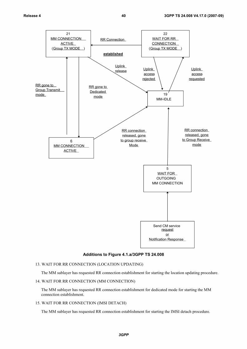
3GPP
3GPP TS 24.008 V4.17.0 (2007-09)Release 4 40
RR gone toGroup Transmitmode
21MM CONNECTION
ACTIVE(Group TX MODE )
22WAIT FOR RRCONNECTION
(Group TX MODE )
RR Connection
established
6MM CONNECTION
ACTIVE
19MM-IDLE
5WAIT FOR
OUTGOINGMM CONNECTION
Send CM servicerequest
orNotification Response
RR gone toDedicated
mode
Uplinkrelease Uplink
accessrejected
Uplinkaccess
requested
RR connectionreleased, gone
to group receiveMode
RR connectionreleased, gone
to Group Receivemode
Additions to Figure 4.1.a/3GPP TS 24.008
13. WAIT FOR RR CONNECTION (LOCATION UPDATING)
The MM sublayer has requested RR connection establishment for starting the location updating procedure.
14. WAIT FOR RR CONNECTION (MM CONNECTION)
The MM sublayer has requested RR connection establishment for dedicated mode for starting the MMconnection establishment.
15. WAIT FOR RR CONNECTION (IMSI DETACH)
The MM sublayer has requested RR connection establishment for starting the IMSI detach procedure.
3GPP
3GPP TS 24.008 V4.17.0 (2007-09)Release 4 41
17. WAIT FOR REESTABLISH
A lower layer failure has occurred and re-establishment may be performed from the disturbed CM layerentities.
18. WAIT FOR RR ACTIVE
The MM sublayer has requested activation of the RR sublayer.
19. MM IDLE
There is no MM procedure running and no RR connection exists except that a local MM context may existwhen the RR sublayer is in Group Receive mode. This is a compound state, and the actual behaviour of themobile station to Connection Management requests is determined by the actual substate as describedhereafter.
20. WAIT FOR ADDITIONAL OUTGOING MM CONNECTION.
The MM connection establishment for an additional MM connection has been started, and the MM awaitsresponse from the network.
21. MM CONNECTION ACTIVE (GROUP TRANSMIT MODE)
(Only applicable for mobile stations supporting VGCS talking:) The MM sublayer has a RR connection onthe VGCS channel to its peer entity on the network side. Only one MM connection is active.
22. WAIT FOR RR CONNECTION (GROUP TRANSMIT MODE)
(Only applicable for mobile stations supporting VGCS talking:) The MM sublayer has requested to performan uplink access on the VGCS channel.
23. LOCATION UPDATING PENDING
(Only applicable for GPRS MS operation modes A and B; not shown in figure 4.1a) A location updating hasbeen started using the combined GPRS routing area updating procedure.
24. IMSI DETACH PENDING
(Only applicable for GPRS MS operation modes A and B; not shown in figure 4.1a) An IMSI detach for non-GPRS services has been started using the combined GPRS detach procedure at not switching off.
25. RR CONNECTION RELEASE NOT ALLOWED
(Only applicable for mobile stations supporting RRLP procedures (see 3GPP TS 44.031 [23b]) or LCSprocedures over RRC (see 3GPP TS 25.331 [23c])). All MM connections are released by their CM entities,but the RR connection is maintained by the network due to an ongoing RRLP procedure or LCS procedureover RRC.
4.1.2.1.2 Substates of the MM IDLE state
For the description of the behaviour of the MS the MM IDLE state is subdivided in several substates, also called theservice states. The service state pertains to the whole MS (ME alone if no SIM is inserted, or ME plus SIM.). Theservice state depends on the update status (see subclause 4.1.2.2) and on the selected cell.
19.1 NORMAL SERVICE
Valid subscriber data are available, update status is U1, a cell is selected that belongs to the LA where thesubscriber is registered.
In this state, all requests from the CM layers are treated normally.
19.2 ATTEMPTING TO UPDATE
Valid subscriber data are available, update status is U2 and a cell is selected. Requests from upper layers areaccepted. Emergency call requests are treated normally, otherwise the request triggers first a location

3GPP
3GPP TS 24.008 V4.17.0 (2007-09)Release 4 42
updating attempt in the selected cell, and then triggers the needed procedure only in case of successfullocation updating, otherwise the request is rejected.
19.3 LIMITED SERVICE
Valid subscriber data are available, update status is U3, and a cell is selected, which is known not to be ableto provide normal service. Only emergency services are offered.
19.4 NO IMSI
No valid subscriber data (no SIM, or the SIM is not considered valid by the ME), and a cell is selected. Onlyemergency services are offered.
19.5 NO CELL AVAILABLE
No cell can be selected. This state is entered after a first intensive search failed (state 19.7). Cells aresearched at a low rhythm. No services are offered.
19.6 LOCATION UPDATE NEEDED
Valid subscriber data are available, and for some reason a location updating must be done as soon as possible(for instance update status is U1 but the selected cell is not in the registered LA, or the timer has expired, ...).This state is usually of no duration, but can last, e.g., in the case of access class blocking.
19.7 PLMN SEARCH
The mobile station is searching for PLMNs, and the conditions for state 19.8 are not met. This state is endedwhen either a cell is selected (the new state is 19.1, 19.3 or 19.6), or when it is concluded that no cell isavailable for the moment (the new state is 19.5).
19.8 PLMN SEARCH, NORMAL SERVICE
Valid subscriber data are available, update status is U1, a cell is selected which belongs to the LA where thesubscriber is registered, and the mobile station is searching for PLMNs. This state is ended when either a cellis selected (the new state is 19.1, 19.3 or 19.6), or when it is concluded that no cell is available for themoment (the new state is 19.5).
19.9 RECEIVING GROUP CALL (NORMAL SERVICE)
Only applicable for mobile stations supporting VGCS listening or VBS listening. Valid subscriber data areavailable, update status is U1, a VGCS channel or VBS channel is received in a cell that belongs to the LAwhere the subscriber is registered.
In this state, only requests from the GCC or BCC layers are treated.
19.10 RECEIVING GROUP CALL (LIMITED SERVICE)
Only applicable for mobile stations supporting VGCS listening or VBS listening. Valid subscriber data areavailable, update status is U3, a VGCS channel or VBS channel is received in a cell which is known not to beable to provide normal service.
In this state, only requests from the GCC or BCC layers for the reception of VGCS or VBS calls are treatedand group call emergency services are offered.
4.1.2.2 The update Status
In parallel with the sublayer states described in subclause 4.1.2.1 and which control the MM sublayer protocol, anupdate status exists.
The update status pertains to a specific subscriber embodied by a SIM. This status is defined even when the subscriberis not activated (SIM removed or connected to a switched-off ME). It is stored in a non volatile memory in the SIM.The update status is changed only as a result of a location updating procedure attempt (with the exception of anauthentication failure and of some cases of CM service rejection). In some cases, the update status is changed as a resultof a GPRS attach, GPRS routing area update, service request or network initiated GPRS detach procedure.
U1 UPDATED
3GPP
3GPP TS 24.008 V4.17.0 (2007-09)Release 4 43
The last location updating attempt was successful (correct procedure outcome, and the answer wasacceptance from the network). With this status, the SIM contains also the LAI of the LA where the subscriberis registered, and possibly valid TMSI, GSM ciphering key, UMTS integrity key, UMTS ciphering key andciphering key sequence number. The "Location update status" stored on the SIM shall be "updated".
U2 NOT UPDATED
The last location updating attempt made failed procedurally (no significant answer was received from thenetwork, including the cases of failures or congestion inside the network).
For this status, the SIM does not contain any valid LAI, TMSI, GSM ciphering key, UMTS integrity key,UMTS ciphering key or ciphering key sequence number. For compatibility reasons, all these fields must beset to the "deleted" value at the moment the status is set to NOT UPDATED. However the presence of othervalues shall not be considered an error by the mobile station. The "Location update status" stored on the SIMshall be "not updated".
U3 ROAMING NOT ALLOWED
The last location updating attempt run correctly, but the answer from the network was negative (because ofroaming or subscription restrictions).
For this status, the SIM may contain a valid LAI, TMSI, GSM ciphering key, UMTS integrity key, UMTSciphering key or ciphering key sequence number. For compatibility reasons, all these fields must be set to the"deleted" value if the LAI is deleted. However the presence of other values shall not be considered an errorby the mobile station. The "Location update status" stored on the SIM shall be "Location Area not allowed".
4.1.2.3 MM sublayer states on the network side
1. IDLE
The MM sublayer is not active except possibly when the RR sublayer is in Group Receive mode.
2. WAIT FOR RR CONNECTION
The MM sublayer has received a request for MM connection establishment from the CM layer. A RRconnection to the mobile station is requested from the RR sublayer (i.e. paging is performed).
3. MM CONNECTION ACTIVE
The MM sublayer has a RR connection to a mobile station. One or more MM connections are active, or noMM connection is active but an RRLP procedure or LCS procedure over RRC is ongoing.
4. IDENTIFICATION INITIATED
The identification procedure has been started by the network. The timer T3270 is running.
5. AUTHENTICATION INITIATED
The authentication procedure has been started by the network. The timer T3260 is running.
6. TMSI REALLOCATION INITIATED
The TMSI reallocation procedure has been started by the network. The timer T3250 is running.
7. SECURITY MODE INITIATED
In UMTS, the security mode setting procedure has been requested to the RR sublayer. In GSM, the ciphermode setting procedure has been requested to the RR sublayer.
8a. WAIT FOR MOBILE ORIGINATED MM CONNECTION
A CM SERVICE REQUEST message is received and processed, and the MM sublayer awaits the "openingmessage" of the MM connection.
8b. WAIT FOR NETWORK ORIGINATED MM CONNECTION

3GPP
3GPP TS 24.008 V4.17.0 (2007-09)Release 4 44
A CM SERVICE PROMPT message has been sent by the network and the MM sublayer awaits the "openingmessage" of the MM connection $(CCBS)$.
9. WAIT FOR REESTABLISHMENT
The RR connection to a mobile station with one or more active MM connection has been lost. The networkawaits a possible re-establishment request from the mobile station.
10. WAIT OF A GROUP CALL
Only applicable in case for mobile station supporting VGCS talking. The MM sublayer has received arequest for establishing a VGCS from the GCC sublayer. The request for establishing a VGCS channels isgiven to the RR sublayer.
11. GROUP CALL ACTIVE
Only applicable in case of mobile station supporting VGCS talking. A VGCS channel is established by theRR sublayer. An RR connection to the talking mobile station can be established by the RR sublayer on theVGCS channel. The MM sublayer is active but no sending of MM message between the network and themobile station has occurred.
12. MM CONNECTION ACTIVE (GROUP CALL)
Only applicable in case of mobile station supporting VGCS talking. The MM sublayer has a RR connectionto the talking mobile station on the VGCS channel. Only one MM connection is active.
13. WAIT FOR BROADCAST CALL
Only applicable in case of VBS. The MM sublayer has received a request for a VBS establishment from theBCC sublayer. The request for establishment of VBS channels is given to the RR sublayer.
14. BROADCAST CALL ACTIVE
Only applicable in case of VBS. A VBS channel is established by the RR sublayer. The MM sublayer isactive but no explicit MM establishment between the Network and the mobile station has occurred.
4.1.3 GPRS mobility management (GMM) sublayer statesIn this subclause, the GMM protocol of the MS and the network are described by means of two different state machines.In subclause 4.1.3.1, the states of the GMM entity in the MS are introduced. The behaviour of the MS depends on aGPRS update status that is described in subclause 4.1.3.2. The states for the network side are described insubclause 4.1.3.3.
4.1.3.1 GMM states in the MS
In this subclause, the possible GMM states are described of a GMM entity in the mobile station. subclause 4.1.3.1.1summarises the main states of a GMM entity, see figure 4.1b of the present document. The substates that have beendefined are described in subclause 4.1.3.1.2 and subclause 4.1.3.1.3.
However, it should be noted that this subclause does not include a description of the detailed behaviour of the MS in thesingle states and does not cover abnormal cases. Thus, figure 4.1b of the present document is rather intended to give anoverview of the state transitions than to be a complete state transition diagram. A detailed description of the behaviourof the MS is given in subclause 4.2. Especially, with respect to the behaviour of the MS in abnormal cases it is referredto subclause 4.7.
4.1.3.1.1 Main states
4.1.3.1.1.1 GMM-NULL
The GPRS capability is disabled in the MS. No GPRS mobility management function shall be performed in this state.
3GPP
3GPP TS 24.008 V4.17.0 (2007-09)Release 4 45
4.1.3.1.1.2 GMM-DEREGISTERED
The GPRS capability has been enabled in the MS, but no GMM context has been established. In this state, the MS mayestablish a GMM context by starting the GPRS attach or combined GPRS attach procedure.
4.1.3.1.1.3 GMM-REGISTERED-INITIATED
A GPRS attach or combined GPRS attach procedure has been started and the MS is awaiting a response from thenetwork.
4.1.3.1.1.4 GMM-REGISTERED
A GMM context has been established, i.e. the GPRS attach or combined GPRS attach procedure has been successfullyperformed. In this state, the MS may activate PDP contexts, may send and receive user data and signalling informationand may reply to a page request. Furthermore, cell and routing area updating are performed.
4.1.3.1.1.5 GMM-DEREGISTERED-INITIATED
The MS has requested release of the GMM context by starting the GPRS detach or combined GPRS detach procedure.This state is only entered if the MS is not being switched off at detach request.
4.1.3.1.1.6 GMM-ROUTING-AREA-UPDATING-INITIATED
A routing area updating procedure has been started and the MS is awaiting a response from the network.
4.1.3.1.1.7 GMM-SERVICE-REQUEST-INITIATED (UMTS only)
A service request procedure has been started and the MS is awaiting a response from the network.
4.1.3.1.2 Substates of state GMM-DEREGISTERED
The GMM-DEREGISTERED state is subdivided into several substates as explained below. The substates pertain to thewhole MS (ME alone if no SIM is inserted, or ME plus SIM). The selection of the appropriate substate depends on theGPRS update status, see subclause 4.1.3.2, and on the selected cell.
4.1.3.1.2.1 GMM-DEREGISTERED.NORMAL-SERVICE
Valid subscriber data is available, the GPRS update status is GU1 or GU2, a cell has been selected. In this state, arequest for GPRS attach is performed using the stored temporary mobile subscriber identity for GPRS (P-TMSI),routing area identification (RAI) and GPRS ciphering key sequence number in case of GU1. If the GPRS update statusis GU2, the IMSI shall be used to attach for GPRS services.
4.1.3.1.2.2 GMM-DEREGISTERED.LIMITED-SERVICE
Valid subscriber data is available, GPRS update status is GU3, and a cell is selected, which is known not to be able toprovide normal service.
4.1.3.1.2.3 GMM-DEREGISTERED.ATTACH-NEEDED
Valid subscriber data is available and for some reason a GPRS attach must be performed as soon as possible. This stateis usually of no duration, but can last, e.g. if the access class is blocked.
4.1.3.1.2.4 GMM-DEREGISTERED.ATTEMPTING-TO-ATTACH
The GPRS update status is GU2, a cell is selected, a previous GPRS attach was rejected. The execution of further attachprocedures depends on the GPRS attach attempt counter. No GMM procedure except GPRS attach shall be initiated bythe MS in this substate.
3GPP
3GPP TS 24.008 V4.17.0 (2007-09)Release 4 46
4.1.3.1.2.5 GMM-DEREGISTERED.NO-IMSI
No valid subscriber data is available (no SIM, or the SIM is not considered valid by the ME) and a cell has beenselected.
4.1.3.1.2.6 GMM-DEREGISTERED.NO-CELL-AVAILABLE
No cell can be selected. This substate is entered after a first intensive search failed (substate PLMN SEARCH). Cellsare searched for at a low rhythm. No services are offered.
4.1.3.1.2.7 GMM-DEREGISTERED.PLMN-SEARCH
The mobile station is searching for PLMNs. This substate is left either when a cell has been selected (the new substateis NORMAL-SERVICE or LIMITED-SERVICE) or when it has been concluded that no cell is available at the moment(the new substate is NO-CELL-AVAILABLE).
4.1.3.1.2.8 GMM-DEREGISTERED.SUSPENDED (GSM only)
The MS shall enter this substate when entering dedicated mode and the MS limitations make it unable to communicateon GPRS channels. The MS shall leave this substate when leaving dedicated mode.
4.1.3.1.3 Substates of state GMM-REGISTERED
The state GMM-REGISTERED is subdivided into several substate as explained below. The substates pertain to thewhole MS (ME alone if no SIM is inserted, or ME plus SIM.).
4.1.3.1.3.1 GMM-REGISTERED.NORMAL-SERVICE
User data and signalling information may be sent and received.
4.1.3.1.3.2 GMM-REGISTERED.SUSPENDED (GSM only)
The MS shall enter this substate when entering dedicated mode and when the MS limitations makes it unable tocommunicate on GPRS channels... In this substate, no user data should be sent and no signalling information shall besent. The MS shall leave this substate when leaving dedicated mode.
4.1.3.1.3.3 GMM-REGISTERED.UPDATE-NEEDED
The MS has to perform a routing area updating procedure, but its access class is not allowed in the cell. The procedurewill be initiated as soon as access is granted (this might be due to a cell-reselection or due to change of the access classof the current cell). No GMM procedure except routing area updating shall be initiated by the MS in this substate. Inthis substate, no user data and no signalling information shall be sent.
4.1.3.1.3.4 GMM-REGISTERED.ATTEMPTING-TO-UPDATE
A routing area updating procedure failed due to a missing response from the network. The MS retries the procedurecontrolled by timers and a GPRS attempt counter. No GMM procedure except routing area updating shall be initiated bythe MS in this substate. No data shall be sent or received.
4.1.3.1.3.5 GMM-REGISTERED.NO-CELL-AVAILABLE
GPRS coverage has been lost. In this substate, the MS shall not initiate any GMM procedures except of cell (andPLMN) reselection.
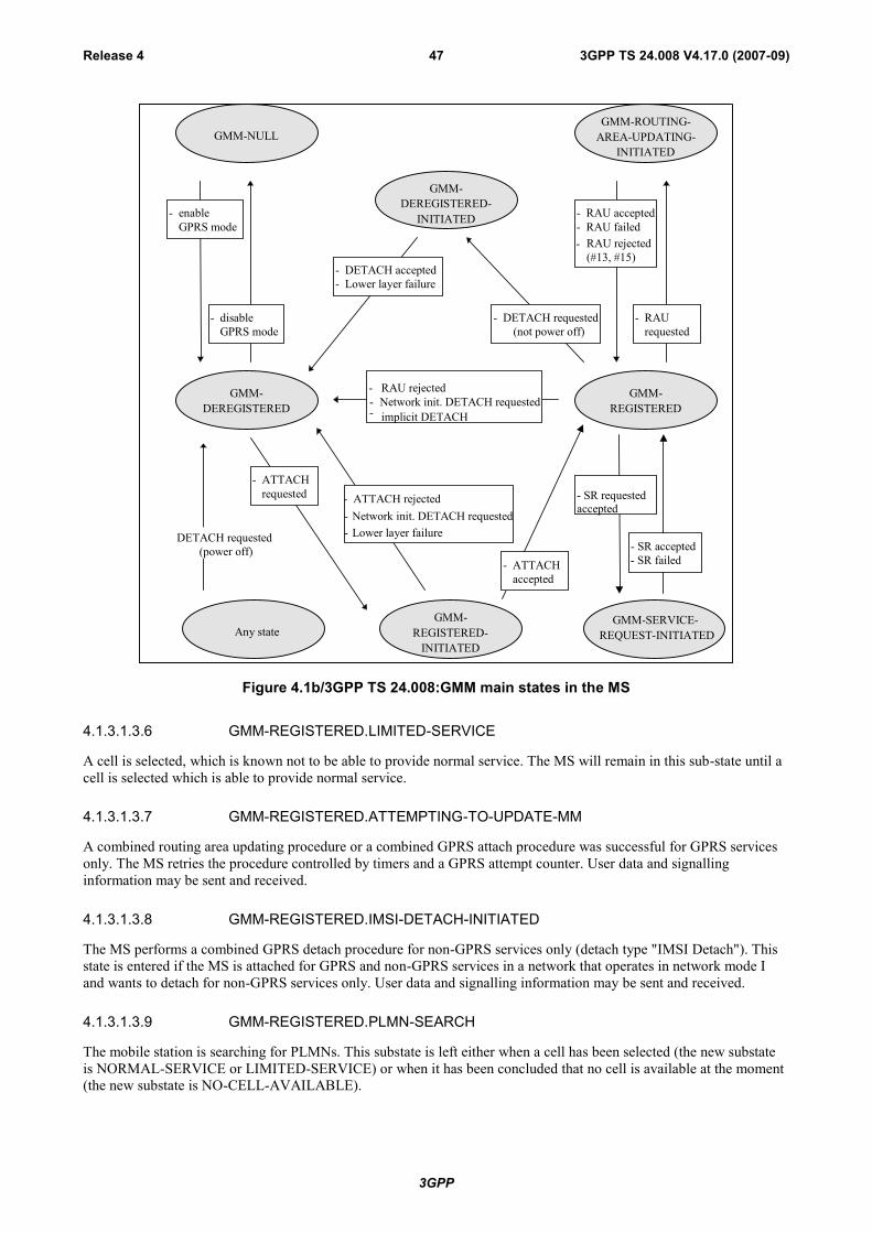
3GPP
3GPP TS 24.008 V4.17.0 (2007-09)Release 4 47
GMM-NULLGMM-ROUTING-
AREA-UPDATING-INITIATED
GMM-DEREGISTERED
- enableGPRS mode
- DETACH requested(not power off)
GMM-REGISTERED
Any state
GMM-DEREGISTERED-
INITIATED
- ATTACHrequested - ATTACH rejected
DETACH requested (power off)
- Network init. DETACH requested- Lower layer failure
- RAU rejected- Network init. DETACH requested- implicit DETACH
- DETACH accepted- Lower layer failure
- disableGPRS mode
- RAUrequested
- RAU accepted- RAU failed
GMM-REGISTERED-
INITIATED
GMM-SERVICE-REQUEST-INITIATED
- SR accepted- SR failed
- SR requestedaccepted
- ATTACHaccepted
RAU rejected(#13, #15)
-
Figure 4.1b/3GPP TS 24.008:GMM main states in the MS
4.1.3.1.3.6 GMM-REGISTERED.LIMITED-SERVICE
A cell is selected, which is known not to be able to provide normal service. The MS will remain in this sub-state until acell is selected which is able to provide normal service.
4.1.3.1.3.7 GMM-REGISTERED.ATTEMPTING-TO-UPDATE-MM
A combined routing area updating procedure or a combined GPRS attach procedure was successful for GPRS servicesonly. The MS retries the procedure controlled by timers and a GPRS attempt counter. User data and signallinginformation may be sent and received.
4.1.3.1.3.8 GMM-REGISTERED.IMSI-DETACH-INITIATED
The MS performs a combined GPRS detach procedure for non-GPRS services only (detach type "IMSI Detach"). Thisstate is entered if the MS is attached for GPRS and non-GPRS services in a network that operates in network mode Iand wants to detach for non-GPRS services only. User data and signalling information may be sent and received.
4.1.3.1.3.9 GMM-REGISTERED.PLMN-SEARCH
The mobile station is searching for PLMNs. This substate is left either when a cell has been selected (the new substateis NORMAL-SERVICE or LIMITED-SERVICE) or when it has been concluded that no cell is available at the moment(the new substate is NO-CELL-AVAILABLE).
3GPP
3GPP TS 24.008 V4.17.0 (2007-09)Release 4 48
4.1.3.2 GPRS update status
In addition to the GMM sublayer states described so far, a GPRS update status exists.
The GPRS update status pertains to a specific subscriber embodied by a SIM. This status is defined even when thesubscriber is not activated (SIM removed or connected to a switched off ME). It is stored in a non volatile memory inthe SIM. The GPRS update status is changed only after execution of a GPRS attach, network initiated GPRS detach,authentication procedure, or routing area updating procedure.
GU1: UPDATED
The last GPRS attach or routing area updating attempt was successful (correct procedure outcome, and theanswer was accepted by the network). The SIM contains the RAI of the routing area (RA) to which thesubscriber was attached, and possibly a valid P-TMSI, GPRS GSM ciphering key, GPRS UMTS ciphering key,GPRS UMTS integrity key and GPRS ciphering key sequence number.
GU2: NOT UPDATED
The last GPRS attach or routing area updating attempt failed procedurally, i.e. no response was received fromthe network. This includes the cases of failures or congestion inside the network.
In this case, the SIM may contain the RAI of the routing area (RA) to which the subscriber was attached, andpossibly also a valid P-TMSI, GPRS GSM ciphering key, GPRS UMTS ciphering key, GPRS UMTS integritykey and GPRS ciphering key sequence number. For compatibility reasons, all these fields shall be set to the"deleted" value if the RAI is deleted. However, the presence of other values shall not be considered an error bythe MS.
GU3: ROAMING NOT ALLOWED
The last GPRS attach or routing area updating attempt was correctly performed, but the answer from the networkwas negative (because of roaming or subscription restrictions).
In this case, the SIM may contain the RAI of the routing area (RA) to which the subscriber was attached, andpossibly also a valid P-TMSI, GPRS GSM ciphering key, GPRS UMTS ciphering key, GPRS UMTS integritykey or GPRS ciphering key sequence number. For compatibility reasons, all these fields shall be set to the value"deleted" if the RAI is deleted. However, the presence of other values shall not be considered an error by theMS.
4.1.3.3 GMM mobility management states on the network side
In this subsubclause, the possible states are described for the GMM on the network side. Subclause 4.1.3.3.1summarises the main states. The corresponding substates are described in subclause 4.1.3.3.2.
However, it should be noted that this subclause does not include a description of the detailed behaviour of the networkin the single states and does not cover abnormal cases. Thus, figure 4.1c/3GPP TS 24.008 is rather intended to give anoverview of the state transitions than to be a complete state transition diagram. A detailed description of the behaviourof the MS is given in subclause 4.2. Especially, with respect to the behaviour of the MS in abnormal cases it is referredto subclause 4.7.
4.1.3.3.1 Main States
4.1.3.3.1.1 GMM-DEREGISTERED
The network has no GMM context or the GMM context is marked as detached, the MS is detached. In this state, thenetwork may answer to a GPRS attach or combined GPRS attach procedure initiated by the MS.
4.1.3.3.1.2 GMM-COMMON-PROCEDURE-INITIATED
A common GMM procedure, as defined in subclause 4.1.1, has been started. The network is awaiting the answer fromthe MS.

3GPP
3GPP TS 24.008 V4.17.0 (2007-09)Release 4 49
4.1.3.3.1.3 GMM-REGISTERED
The GMM context has been established and the GPRS attach procedure has been successfully performed.
4.1.3.3.1.4 GMM-DEREGISTERED-INITIATED
The network has started a GPRS detach procedure and is awaiting the answer from the MS.
GMM-DE-REGISTERED
- Network initiatedDETACH requested
GMM-REGISTERED
GMM-COMMON-PROCEDURE-INITIATED
GMM-DE-REGISTERED-
INITIATED
- COMMON procedurefailed
- Lower layer failure
- ATTACH proceduresuccessful
- MS initiatedDETACH requestedRAU rejectedimplicit DETACH
- DETACH accepted- Lower layer failure
- COMMON proceduresuccessful
- ATTACH proceduresuccessful
- COMMON procedurerequested
- COMMON procedurerequested
Figure 4.1c/3GPP TS 24.008: GMM main states on the network side
4.1.3.3.2 Substates of state GMM-REGISTERED
The state GMM-REGISTERED is subdivided into two substates as explained below.
4.1.3.3.2.1 GMM-REGISTERED.NORMAL-SERVICE
User data and signalling information may be sent and received.
4.1.3.3.2.2 GMM-REGISTERED.SUSPENDED (GSM only)
In this substate, the lower layers shall be prevented of sending user data or signalling information.
4.2 Behaviour of the MS in MM Idle state, GMM-DEREGISTERED state and GMM-REGISTERED state
In this subclause, the detailed behaviour of the MS in the main states MM IDLE, GMM-DEREGISTERED and GMM-REGISTERED is described. Subclauses 4.2.1 to 4.2.3 refer to the state MM IDLE, whereas subclauses 4.2.4 and 4.2.5refer to the states GMM-DEREGISTERED and GMM-REGISTERED, respectively.
The MM IDLE state is entered when none of the MM procedures are running and no RR connection exists. It is leftwhen one of the MM procedures are triggered or a RR connection is established.
3GPP
3GPP TS 24.008 V4.17.0 (2007-09)Release 4 50
The specific behaviour in the MM IDLE state depends on the service state of the mobile station as described insubclause 4.1.2.1.2. The service state depends in particular on the update status which is defined in subclause 4.1.2.2.
How an appropriate service state is chosen after power on is described in subclause 4.2.1, and the specific behaviour ofthe mobile station in MM IDLE state is described in subclause 4.2.2. The service state chosen when the MM IDLE stateis returned to from any state except NULL state is described in 4.2.3.
It should be noted that transitions between the various MM idle states are caused by (e.g.):
- results of procedures on RR connected mode (see subclause 4.2.3);
- insertion or removal of the SIM;
- cell selection/reselection (see also 3GPP TS 43.022 [82]);
- PLMN search;
- loss of coverage.
How various MM procedures affects the service state and the update status is described in the detailed descriptions ofthe procedures in subclauses 4.3 to 4.5.
4.2.1 Primary Service State selection
4.2.1.1 Selection of the Service State after Power On.
When mobility management is activated after power-on, the service state is 19.7 PLMN SEARCH. The detailedprocessing in this state is described in detail in 3GPP TS 43.022 [82] and 45.008 [34], where procedures for power onand selection of PLMN is described in detail. If the "Location update status" stored on the SIM is different from"updated", then the mobile shall act as if the "Location update status" stored on the SIM is "not updated".
The service state when the PLMN SEARCH state is left depends on the outcome of the search and on the presence ofthe SIM:
- if no cell has been found, the state is NO CELL AVAILABLE, until a cell is found;
- if no SIM is present the state is NO IMSI;
- if the mobile station has been continuously activated since loosing coverage and then returns to coverage, and ifthe selected cell is in the location area where the mobile station is registered and the timer T3212 has notexpired, then the state is NORMAL SERVICE;
- if the selected cell is in the location area where the mobile station is registered and IMSI ATTACH is notrequired and timer T3212 has not expired, then the state is NORMAL SERVICE;
- if the mobile station is in automatic network selection mode and the selected cell is in a forbidden PLMN or aforbidden LA, then the mobile station enters the LIMITED SERVICE state;
- if the mobile station is in manual network selection mode and no cell of the selected PLMN has been found, thenthe mobile station enters the LIMITED SERVICE state;
- otherwise, the mobile station enters the LOCATION UPDATE NEEDED state.
4.2.1.2 Other Cases
The state PLMN SEARCH is also entered in the following cases:
- in state NO IMSI, a SIM is inserted;
- in any state except NO IMSI, NO CELL AVAILABLE, NORMAL SERVICE and RECEIVING GROUP CALL(NORMAL SERVICE) after the user has asked for a PLMN selection;
- in any state except NO IMSI and NO CELL AVAILABLE, coverage is lost;
- roaming is denied;
3GPP
3GPP TS 24.008 V4.17.0 (2007-09)Release 4 51
- optionally, when the mobile station is in the ATTEMPTING TO UPDATE state and is in Automatic NetworkSelection mode and location update attempt counter is greater than or equal to 4.
The service state when the PLMN SEARCH is left depends on the outcome of the search and on the presence of theSIM as specified in subclause 4.2.1.1.
4.2.2 Detailed Description of the MS behaviour in MM IDLE State.In the MM IDLE state the mobile station shall behave according to the service state. In the following subclauses thebehaviour is described for the non transient service states. It should be noted that after procedures in RR connectedmode, e.g. location updating procedures, subclause 4.2.3 applies which specifies the selection of the MM idle state.Furthermore when in sub-state NORMAL SERVICE, if a PLMN selection is requested, the MS enters sub-stateSEARCH FOR PLMN, NORMAL SERVICE.
4.2.2.1 Service State, NORMAL SERVICE
When in state MM IDLE and service state NORMAL SERVICE, the mobile station shall:
- perform normal location updating when a new location area is entered;
- perform location updating procedure at expiry of timer T3211 or T3213;
- perform periodic updating at expiration of timer T3212;
- perform IMSI detach;
- support requests from the CM layer;
- respond to paging.
In addition, mobile stations supporting VGCS listening or VBS listening shall:
- indicate notifications to the GCC or BCC sublayer;
- respond to notification if the GCC or BCC sublayer requests the reception of a voice group or broadcast call forwhich no channel description has been received in the notification by the RR sublayer;
- request the RR sublayer to receive a voice group or broadcast call if the GCC or BCC sublayer requests thereception of a voice group or broadcast call for which a channel description has been received in the notificationby the RR sublayer and then go to the service state RECEIVING GROUP CALL (NORMAL SERVICE).
4.2.2.2 Service State, ATTEMPTING TO UPDATE
When in state MM IDLE and service state ATTEMPTING TO UPDATE the mobile station shall:
- perform location updating procedure at expiry of timer T3211 or T3213;
- perform normal location updating when the location area identification of the serving cell changes;
- if entry into this state was caused by c) or d) or f) (with cause different from "abnormal release, unspecified") org) (with cause "retry upon entry into a new cell") of subclause 4.4.4.9, then location updating shall be performedwhen a new cell is entered;
- if entry into this state was caused by e) or f) (with cause "abnormal release, unspecified") or g) (with causedifferent from "retry upon entry into a new cell") of subclause 4.4.4.9, then location updating shall not beperformed because a new cell is entered;
- perform normal location updating at expiry of timer T3212;
- not perform IMSI detach;
- support request for emergency calls;
- use other request from CM layer as triggering of normal location updating procedure (if the location updatingprocedure is successful, then the request for MM connection is accepted, see subclause 4.5.1);
3GPP
3GPP TS 24.008 V4.17.0 (2007-09)Release 4 52
- respond to paging (with IMSI).
In addition, mobile stations supporting VGCS listening or VBS listening shall:
- indicate notifications to the GCC or BCC sublayer for which a channel description has been received in thenotification by the RR sublayer;
- reject requests of the GCC or BCC sublayer to respond to notifications for which no channel description hasbeen received in the notification by the RR sublayer;
- request the RR sublayer to receive a voice group or broadcast call if the GCC or BCC sublayer requests thereception of a voice group or broadcast call for which a channel description has been received in the notificationby the RR sublayer and then go to the service state RECEIVING GROUP CALL (LIMITED SERVICE).
4.2.2.3 Service State, LIMITED SERVICE
When in state MM IDLE and service state LIMITED SERVICE the mobile station shall:
- not perform periodic updating;
- not perform IMSI detach;
- reject any requests from CM entities for MM connections except for emergency calls;
- perform normal location updating when a cell is entered which may provide normal service (e.g. location areanot in one of the forbidden LAI lists.);
- it may respond to paging (with IMSI).
In addition, mobile stations supporting VGCS listening or VBS listening shall:
- indicate notifications to the GCC or BCC sublayer for which a channel description has been received in thenotification by the RR sublayer;
- reject requests of the GCC or BCC sublayer to respond to notifications for which no channel description hasbeen received in the notification by the RR sublayer;
- request the RR sublayer to receive a voice group or broadcast call if the GCC or BCC sublayer requests thereception of a voice group or broadcast call for which a channel description has been received in the notificationby the RR sublayer and then go to the service state RECEIVING GROUP CALL (LIMITED SERVICE).
4.2.2.4 Service State, NO IMSI
When in state MM IDLE and service state NO IMSI the mobile station shall (see subclause 3.2, 3GPP TS 43.022 [82]and 3GPP TS 45.008 [34]):
- not start any normal location updating attempt;
- not perform periodic updating;
- not perform IMSI detach if powered down;
- reject any request from CM entities for MM connections except for emergency calls;
- not respond to paging;
- only perform default cell selection.
In addition, mobile stations supporting VGCS listening or VBS listening shall:
- not indicate notifications to the GCC or BCC layer.
3GPP
3GPP TS 24.008 V4.17.0 (2007-09)Release 4 53
4.2.2.5 Service State, SEARCH FOR PLMN, NORMAL SERVICE
When in state MM IDLE and service state SEARCH FOR PLMN, NORMAL SERVICE the mobile station shall:
- if timer T3211 or T3213 expires in this state perform a location updating procedure at the latest if and when backto NORMAL SERVICE state and if the cell is not changed;
- if timer T3212 expires in this state perform a periodic location updating procedure at the latest if and when backto NORMAL SERVICE state;
- perform IMSI detach;
- support requests from the CM layer;
- listen as far as possible to paging, and respond.
In addition, mobile stations supporting VGCS listening or VBS listening shall:
- listen as far as possible to notifications and indicate notifications to the GCC or BCC layer;
- respond to notification if the GCC or BCC sublayer requests the reception of a voice group or broadcast call forwhich no channel description has been received in the notification by the RR sublayer;
- request the RR sublayer to receive a voice group or broadcast call if the GCC or BCC sublayer requests thereception of a voice group or broadcast call for which a channel description has been received in the notificationby the RR sublayer.
4.2.2.6 Service State, SEARCH FOR PLMN
When in state MM IDLE and service state SEARCH FOR PLMN the mobile station shall:
- not start any normal location updating attempt;
- not perform periodic updating;
- not perform IMSI detach if powered down;
- reject any request from CM entities for MM connections except emergency calls;
- not respond to paging.
4.2.2.7 Service State, RECEIVING GROUP CALL (NORMAL SERVICE)
Only applicable for mobile stations supporting VGCS listening or VBS listening:
When in state MM IDLE and service state RECEIVING GROUP CALL (NORMAL SERVICE), the mobile stationshall:
- perform normal location updating when a new location area is entered;
- perform location updating procedure at expiry of timer T3211 or T3213;
- perform periodic updating at expiration of timer T3212;
- perform IMSI detach;
- support requests from the GCC or BCC layers;
- indicate notifications or paging information to the GCC or BCC layer;
- respond to notification if the GCC or BCC sublayer requests the reception of a voice group or broadcast call forwhich no channel description has been received in the notification by the RR sublayer;
- request the RR sublayer to receive another voice group or broadcast call if the GCC or BCC sublayer requeststhe reception of a voice group or broadcast call for which a channel description has been received in thenotification by the RR sublayer.

3GPP
3GPP TS 24.008 V4.17.0 (2007-09)Release 4 54
4.2.2.8 Service State, RECEIVING GROUP CALL (LIMITED SERVICE)
Only applicable for mobile stations supporting VGCS listening or VBS listening:
When in state MM IDLE and service state RECEIVING GROUP CALL (LIMITED SERVICE), the mobile stationshall:
- not perform periodic updating;
- not perform IMSI detach;
- reject any requests from CM entities for MM connections except for emergency calls;
- perform normal location updating when a cell is entered which may provide normal service (e.g. location areanot in one of the forbidden LAI lists.);
- it may respond to paging (with IMSI);
- indicate notifications to the GCC or BCC sublayer for which a channel description has been received in thenotification by the RR sublayer;
- reject requests of the GCC or BCC sublayer to respond to notifications for which no channel description hasbeen received in the notification by the RR sublayer;
- request the RR sublayer to receive a voice group or broadcast call if the GCC or BCC sublayer requests thereception of a voice group or broadcast call for which a channel description has been received in the notificationby the RR sublayer and then go to the service state RECEIVING GROUP CALL (LIMITED SERVICE).
4.2.3 Service state when back to state MM IDLE from another stateWhen returning to MM IDLE, e.g., after a location updating procedure, the mobile station selects the cell as specified in3GPP TS 43.022 [82]. With one exception, this is a normal cell selection.
If this return to idle state is not subsequent to a location updating procedure terminated with reception of cause"Roaming not allowed in this location area" the service state depends on the result of the cell selection procedure, on theupdate status of the mobile station, on the location data stored in the mobile station and on the presence of the SIM:
- if no cell has been found, the state is NO CELL AVAILABLE, until a cell is found;
- if no SIM is present, or if the inserted SIM is considered invalid by the MS, the state is NO IMSI;
- if the selected cell is in the location area where the MS is registered, then the state is NORMAL SERVICE; itshall be noted that this also includes an abnormal case described in subclause 4.4.4.9;
- (Only applicable for mobile stations supporting VGCS listening or VBS listening.) if the mobile stations was inthe service state RECEIVING GROUP CALL (NORMAL SERVICE) or RECEIVING GROUP CALL(LIMITED SERVICE) before the location updating procedure and the selected cell is in the location area wherethe mobile station is registered, then the state is RECEIVING GROUP CALL (NORMAL SERVICE);
- if the selected cell is in a location area where the mobile station is not registered but in which the MS is allowedto attempt a location update, then the state is LOCATION UPDATE NEEDED;
- if the selected cell is in a location area where the mobile station is not allowed to attempt a location update, thenthe state is LIMITED SERVICE;
- (Only applicable for MSs supporting VGCS listening or VBS listening.) if the MSs was in the service stateRECEIVING GROUP CALL (NORMAL SERVICE) or RECEIVING GROUP CALL (LIMITED SERVICE)before the location updating procedure and the selected cell is in the location area where the MS is not allowedto attempt a location update, then the state is RECEIVING GROUP CALL (LIMITED SERVICE);
- after some abnormal cases occurring during an unsuccessful location updating procedure, as described insubclause 4.4.4.9, the state is ATTEMPTING TO UPDATE.
In case of a return from a location updating procedure to which was answered "Roaming not allowed in this locationarea", the service state PLMN SEARCH is entered as specified in subclause 4.2.1.2.

3GPP
3GPP TS 24.008 V4.17.0 (2007-09)Release 4 55
4.2.4 Behaviour in state GMM-DEREGISTEREDThe state GMM-DEREGISTERED is entered when:
- the MS is switched on;
- the GPRS capability has been enabled in the MS;
- a GPRS detach or combined GPRS detach procedure has been performed; or
- a GMM procedure has failed (except routing area updating, see subclause 4.7.5).
The selection of the appropriate substate of GMM-DEREGISTERED after switching on is described insubclause 4.2.4.1. The specific behaviour of the MS in state GMM-DEREGISTERED is described in subclause 4.2.4.2.The substate chosen when the GMM-DEREGISTERED state is returned to from another state except state GMM-NULL is described in subclause 4.2.4.3.
It should be noted that transitions between the various substates of GMM-DEREGISTERED are caused by (e.g.):
- insertion or removal of the SIM;
- cell selection/reselection (see also 3GPP TS 43.022 [82]);
- PLMN search;
- loss/regain of coverage; or
- change of RA.
How various GMM procedures affect the GMM-DEREGISTERED substates and the GPRS update status is describedin the detailed description of the GMM procedures in subclause 4.7.
4.2.4.1 Primary substate selection
4.2.4.1.1 Selection of the substate after power on or enabling the MS's GPRS capability
When the MS is switched on, the substate shall be PLMN-SEARCH in case the SIM is inserted and valid. See3GPP TS 23.122 [14] and 3GPP TS 45.008 [34] for further details.
When the GPRS capability in an activated MS has been enabled, the selection of the GMM-DEREGISTERED substatedepends on the MM state and the GPRS update status.
The substate chosen after PLMN-SEARCH, in case of power on or after enabling of the GPRS capability is:
- if the cell is not supporting GPRS, the substate shall be NO-CELL-AVAILABLE;
- if no SIM is present the substate shall be NO-IMSI;
- if a cell supporting GPRS has been found and the PLMN or LA is not in the forbidden list, then the substate shallbe NORMAL-SERVICE;
- if the selected cell supporting GPRS is in a forbidden PLMN or a forbidden LA, then the MS shall enter thesubstate LIMITED-SERVICE;
- if the MS is in manual network selection mode and no cell supporting GPRS of the selected PLMN has beenfound, the MS shall enter the substate NO-CELL-AVAILABLE.

3GPP
3GPP TS 24.008 V4.17.0 (2007-09)Release 4 56
4.2.4.1.2 Other Cases
When the MM state is IDLE, the GMM substate PLMN-SEARCH shall also be entered in the following cases:
- when a SIM is inserted in substate NO-IMSI;
- when the user has asked for a PLMN selection in any substate except NO IMSI and NO CELL AVAILABLE ;
- when coverage is lost in any substate except NO IMSI and NO CELL AVAILABLE ;
- Roaming is denied;
- optionally, when the MS is in automatic network selection mode and the maximum allowed number ofsubsequently unsuccessful attach attempts controlled by the GPRS attach attempt counter (subclause 4.7.3) havebeen performed.
4.2.4.2 Detailed description of the MS behaviour in state GMM-DEREGISTERED
In state GMM-DEREGISTERED, the MS shall behave according to the substate. In the following subclauses, thebehaviour is described for the non transient substates.
4.2.4.2.1 Substate, NORMAL-SERVICE
The MS shall:
- perform GPRS attach.
4.2.4.2.2 Substate, ATTEMPTING-TO-ATTACH
The MS shall:
- perform GPRS attach on the expiry of timers T3311 or T3302;
- perform GPRS attach when the routing area of the serving cell has changed and the location area this cell isbelonging to is not in the list of forbidden LAs;
- if entry into this state was caused by b) or d) with cause "Retry upon entry into a new cell" ofsubclause 4.7.3.1.5, GPRS attach shall be performed when a new cell is entered;
- if entry into this state was caused by c) or d) with cause different from "Retry upon entry into a new cell" ofsubclause 4.7.3.1.5, GPRS attach shall not be performed when a new cell is entered; and
- use requests from CM layers to trigger the combined GPRS attach procedure, if the network operates in networkoperation mode I. Depending on which of the timers T3311 or T3302 is running the MS shall stop the relevanttimer and act as if the stopped timer has expired.
4.2.4.2.3 Substate, LIMITED-SERVICE
The MS shall:
- perform GPRS attach when a cell is entered which may provide normal service (e.g. location area is not in one ofthe forbidden lists).
4.2.4.2.4 Substate, NO-IMSI
The MS shall:
- only perform default cell selection.
4.2.4.2.5 Substate, NO-CELL
The MS shall:
- perform cell selection according to 3GPP TS 43.022 [82] and shall choose an appropriate substate.
3GPP
3GPP TS 24.008 V4.17.0 (2007-09)Release 4 57
4.2.4.2.6 Substate, PLMN-SEARCH
No specific action is required in this substate.
4.2.4.2.7 Substate, ATTACH-NEEDED
The MS shall start a GPRS attach procedure if still needed as soon as the access class allows network contact in theselected cell.
4.2.4.2.8 Substate, SUSPENDED (GSM only)
The MS:
- shall not send any user data; and
- shall not send any signalling information.
4.2.4.3 Substate when back to state GMM-DEREGISTERED from another GMMstate
When returning to state GMM-DEREGISTERED, the MS shall select a cell as specified in 3GPP TS 43.022 [82].
The substate depends on the result of the cell selection procedure, the outcome of the previously performed GMMspecific procedures, on the GPRS update status of the MS, on the location area data stored in the MS and on thepresence of the SIM:
- if no cell has been found, the substate is NO-CELL-AVAILABLE, until a cell is found;
- if no SIM is present or if the inserted SIM is considered invalid by the MS, the substate shall be NO-IMSI;
- if the selected cell is in a location area where the MS is allowed to roam, the substate shall be NORMAL-SERVICE;
- if a GPRS attach shall be performed (e.g. network requested reattach), the substate shall be ATTEMPTING-TO-ATTACH
- if a PLMN reselection (according to 3GPP TS 23.122 [14]) is needed, the substate shall be PLMN SEARCH
- if the selected cell is in a location area where the MS is not allowed to roam, the state shall be LIMITED-SERVICE.
4.2.5 Behaviour in state GMM-REGISTEREDThe state GMM-REGISTERED is entered when:
- a GMM context is established, i.e. the MS is IMSI attached for GPRS services only or for GPRS and non-GPRSservices.
The specific behaviour of the MS in state GMM-REGISTERED is described in subclause 4.2.5.1. The primary substatewhen entering the state GMM-REGISTERED is always NORMAL-SERVICE.
It should be noted that transitions between the various substates of GMM-REGISTERED are caused by (e.g.):
- cell selection/reselection (see also 3GPP TS 43.022 [82]);
- change of RA;
- loss/regain of coverage.
How various GMM procedures affect the GMM-REGISTERED substates is described in the detailed description of theprocedures in subclause 4.7.

3GPP
3GPP TS 24.008 V4.17.0 (2007-09)Release 4 58
4.2.5.1 Detailed description of the MS behaviour in state GMM-REGISTERED
In state GMM-REGISTERED, the MS shall behave according to the substate as explained below.
4.2.5.1.1 Substate, NORMAL-SERVICE
The MS shall:
- perform cell selection/reselection according to 3GPP TS 43.022 [82];
- perform normal and periodic routing area updating; and
- receive and transmit user data and signalling information.
GPRS MSs in operation modes C or A shall answer to paging requests.
GPRS MS in operation mode B may answer to paging requests.
4.2.5.1.2 Substate, SUSPENDED (GSM only)
The MS:
- shall not send any user data;
- shall not send any signalling information; and
- shall not perform cell-updates.
4.2.5.1.3 Substate, UPDATE-NEEDED
The MS shall:
- not send any user data;
- not send any signalling information;
- perform cell selection/reselection according to 3GPP TS 43.022 [82]; and
- chose the appropriate new substate depending on the GPRS update status as soon as the access class allowsnetwork contact in the selected cell.
4.2.5.1.4 Substate, ATTEMPTING-TO-UPDATE
The MS:
- should not send any user data;
- shall perform routing area update on the expiry of timers T3311 or T3302;
- shall perform routing area update when the routing area of the serving cell has changed and the location area thiscell is belonging to is not in the list of forbidden LAs;
- shall if entry into this state was caused by b) or d) with cause "Retry upon entry into a new cell", ofsubclause 4.7.5.1.5, perform routing area updating when a new cell is entered;
- shall if entry into this state was caused by c) or d) with cause different from "Retry upon entry into a new cell" ofsubclause 4.7.5.1.5, not perform routing area updating when a new cell is entered; and
- shall use request from CM layers to trigger the combined routing area update procedure, if the network operatesin network operation mode I. Depending on which of the timers T3311 or T3302 is running the MS shall stop therelevant timer and act as if the stopped timer has expired.
4.2.5.1.5 Substate, NO-CELL-AVAILABLE
The MS shall perform cell selection/reselection according to 3GPP TS 43.022 [82].

3GPP
3GPP TS 24.008 V4.17.0 (2007-09)Release 4 59
4.2.5.1.6 Substate, LIMITED-SERVICE
The MS shall perform cell selection/reselection according to 3GPP TS 43.022 [82];
4.2.5.1.7 Substate, ATTEMPTING-TO-UPDATE-MM
The MS shall:
- perform cell selection/reselection according to 3GPP TS 43.022 [82];
- receive and transmit user data and signalling information;
- perform routing area update indicating "combined RA/LA updating with IMSI attach" on the expiry of timersT3311 or T3302;
- perform routing area update indicating "combined RA/LA updating with IMSI attach" when the routing area ofthe serving cell has changed and the location area this cell is belonging to is not in the list of forbidden LAs.
GPRS MSs in operation modes C or A shall answer to paging requests.
GPRS MS in operation mode B may answer to paging requests.
4.2.5.1.8 Substate, PLMN-SEARCH
When the MM state is IDLE, the GMM substate PLMN-SEARCH may be entered if the MS is in automatic networkselection mode and the maximum allowed number of subsequently unsuccessful routing area update attempts controlledby the GPRS routing area update attempt counter (clause 4.7.5) have been performed. If a new PLMN is selected theMS shall perform the routing area updating procedure.
4.3 MM common proceduresAs described in subclause 4.1.1, a MM common procedure can be initiated at any time whilst a RR connection existsbetween the network and the mobile station.
4.3.1 TMSI reallocation procedureThe purpose of the TMSI reallocation procedure is to provide identity confidentiality, i.e. to protect a user against beingidentified and located by an intruder (see 3GPP TS 42.009, 3GPP TS 43.020 [13] and 3GPP TS 33.102).
If the identity confidentiality service is applied for an IMSI, a Temporary Mobile Subscriber Identity (TMSI) is used foridentification within the radio interface signalling procedures.
The structure of the TMSI is specified in 3GPP TS 23.003 [10]. The TMSI has significance only within a location area.Outside the location area it has to be combined with the Location Area Identifier (LAI) to provide for an unambiguousidentity.
Usually the TMSI reallocation is performed at least at each change of a location area. (Such choices are left to thenetwork operator).
The reallocation of a TMSI can be performed either by a unique procedure defined in this subclause or implicitly by alocation updating procedure using the TMSI. The implicit reallocation of a TMSI is described together with thatprocedure.
If a TMSI provided by a mobile station is unknown in the network e.g. due to a data base failure, the network mayrequire the mobile station to provide its International Mobile Subscriber Identity (IMSI). In this case the identificationprocedure (see subclause 4.3.3) should be used before the TMSI reallocation procedure may be initiated.
The TMSI reallocation can be initiated by the network at any time whilst a RR connection exists between the networkand the mobile station.
NOTE 1: Usually the TMSI reallocation is performed in ciphered mode.

3GPP
3GPP TS 24.008 V4.17.0 (2007-09)Release 4 60
NOTE 2: Normally the TMSI reallocation will take place in conjunction with another procedure, e.g. at locationupdating or at call setup (see 3GPP TS 29.002 [37]).
4.3.1.1 TMSI reallocation initiation by the network
The network initiates the TMSI reallocation procedure by sending a TMSI REALLOCATION COMMAND message tothe mobile station and starts the timer T3250.
The TMSI REALLOCATION COMMAND message contains a new combination of TMSI and LAI allocated by thenetwork or a LAI and the IMSI if the used TMSI shall be deleted. Usually the TMSI-REALLOCATION COMMANDmessage is sent to the mobile station using a RR connection in ciphered mode (see 3GPP TS 43.020 [13] and3GPP TS 33.102).
4.3.1.2 TMSI reallocation completion by the mobile station
Upon receipt of the TMSI REALLOCATION COMMAND message the mobile station stores the Location AreaIdentifier (LAI) in the SIM. If the received identity is the IMSI of the relevant mobile station, the mobile station deletesany TMSI. If the received identity is a TMSI the mobile station stores the TMSI in the SIM. In both cases the mobilestation sends a TMSI REALLOCATION COMPLETE message to the network.
4.3.1.3 TMSI reallocation completion in the network.
Upon receipt of the TMSI REALLOCATION COMPLETE message, the network stops the timer T3250 and eitherconsiders the new TMSI as valid or, if an IMSI was sent to the mobile station, considers the old TMSI as deleted.
If the RR connection is no more needed, then the network will request the RR sublayer to release it (see3GPP TS 44.018 [84] subclause 3.5 and 3GPP TS 25.331 [23c]).
4.3.1.4 Abnormal cases
Mobile station side:
The mobile station shall consider the new TMSI and new LAI, if any, as valid and the old TMSI and old LAI asdeleted as soon as a TMSI REALLOCATION COMMAND or another message containing a new TMSI (e.g.LOCATION UPDATING ACCEPT) is correctly received. Any RR connection failure at a later stage shall nothave any impact on the TMSI and LAI storage.
Network side:
(a) RR connection failure:
If the RR connection is lost before the TMSI REALLOCATION COMPLETE message is received, all MMconnections (if any) shall be released and both the old and the new TMSIs should be considered as occupiedfor a certain recovery time.
During this period the network may:
- use the IMSI for paging in the case of network originated transactions on the CM layer. Upon responsefrom the mobile station the TMSI reallocation is restarted;
- consider the new TMSI as valid if it is used by the mobile station in mobile originated requests for RRconnection;
- use the Identification procedure followed by a new TMSI reallocation if the mobile station uses the oldTMSI.
Other implementations are possible.
(b) Expiry of timer T3250:
The TMSI reallocation is supervised by the timer T3250 in the network. At the first expiry of timer T3250the network may release the RR connection. In this case, the network shall abort the reallocation procedurerelease all MM connections if any, and follow the rules described for RR connection failure above.

3GPP
3GPP TS 24.008 V4.17.0 (2007-09)Release 4 61
Figure 4.1/3GPP TS 24.008: TMSI reallocation sequence
4.3.2 Authentication procedure
4.3.2a Authentication procedure used for a UMTS authentication challenge
The purpose of the authentication procedure is fourfold (see 3GPP TS 33.102):
First to permit the network to check whether the identity provided by the mobile station is acceptable or not;
Second to provide parameters enabling the mobile station to calculate a new UMTS ciphering key;
Third to provide parameters enabling the mobile station to calculate a new UMTS integrity key;
Fourth to permit the mobile station to authenticate the network.
The cases where the authentication procedure should be used are defined in 3GPP TS 33.102.
The UMTS authentication procedure is always initiated and controlled by the network. However, there is the possibilityfor the MS to reject the UMTS authentication challenge sent by the network. UMTS authentication challenge shall besupported by a MS supporting the UMTS authentication algorithm.
NOTE: According to 3GPP TS 33.102, a ME supporting only A/Gb mode need not support the USIM interfaceand in consequence need not support the UMTS authentication algorithm.
A UMTS security context is established in the MS and the network when a UMTS authentication challenge isperformed in GSM or in UMTS. After a successful UMTS authentication, the UMTS ciphering key, the UMTSintegrity key, the GSM ciphering key and the ciphering key sequence number, are stored both in the network and theMS.
4.3.2b Authentication Procedure used for a GSM authentication challengeThe purpose of the authentication procedure is twofold (see 3GPP TS 43.020 [13]):
First to permit the network to check whether the identity provided by the mobile station is acceptable or not;
Second to provide parameters enabling the mobile station to calculate a new GSM ciphering key.
The cases where the authentication procedure should be used are defined in 3GPP TS 42.009 [5].
The authentication procedure is always initiated and controlled by the network. GSM authentication challenge shall besupported by a ME supporting GSM or UMTS radio access.
A GSM security context is established in the MS and the network when a GSM authentication challenge is performed inGSM or in UMTS. However, in UMTS an MS which supports the UMTS authentication algorithm shall not accept aGSM authentication challenge. After a successful GSM authentication, the GSM ciphering key and the ciphering keysequence number, are stored both in the network and the MS.
3GPP
3GPP TS 24.008 V4.17.0 (2007-09)Release 4 62
4.3.2.1 Authentication request by the network
The network initiates the authentication procedure by transferring an AUTHENTICATION REQUEST message acrossthe radio interface and starts the timer T3260. The AUTHENTICATION REQUEST message contains the parametersnecessary to calculate the response parameters (see 3GPP TS 43.020 [13] (in case of GSM authentication challenge)and 3GPP TS 33.102 (in case of an UMTS authentication challenge)). In a GSM authentication challenge, theAUTHENTICATION REQUEST message also contains the GSM ciphering key sequence number allocated to the keywhich may be computed from the given parameters. In a UMTS authentication challenge, the AUTHENTICATIONREQUEST message also contains the ciphering key sequence number allocated to the key set of UMTS ciphering key,UMTS integrity key and GSM ciphering key which may be computed from the given parameters.
4.3.2.2 Authentication response by the mobile station
The mobile station shall be ready to respond upon an AUTHENTICATION REQUEST message at any time whilst aRR connection exists. With exception of the cases described in subclause 4.3.2.5.1, it shall process the challengeinformation and send back an AUTHENTICATION RESPONSE message to the network.
A MS which does not support the UMTS authentication algorithm shall ignore the Authentication Parameter AUTN IEif included in the AUTHENTICATION REQUEST message and shall proceed as in case of a GSM authenticationchallenge. It shall not perform the authentication of the network described in subclause 4.3.2.5.1.
In a GSM authentication challenge, the new GSM ciphering key calculated from the challenge information shalloverwrite the previous GSM ciphering key and any previously stored UMTS ciphering key and UMTS integrity keyshall be deleted. The new GSM ciphering key shall be stored on the SIM together with the ciphering key sequencenumber.
In a UMTS authentication challenge, the new UMTS ciphering key, the new GSM ciphering key and the new UMTSintegrity key calculated from the challenge information shall overwrite the previous UMTS ciphering key, GSMciphering key and UMTS integrity key. The new UMTS ciphering key, GSM ciphering key and UMTS integrity key arestored on the SIM together with the ciphering key sequence number.
The SIM will provide the mobile station with the authentication response, based upon the authentication challengegiven from the ME. A UMTS authentication challenge will result in the SIM passing a RES to the ME. A GSMauthentication challenge will result in the SIM passing a SRES to the ME.
A mobile station supporting UMTS authentication challenge may support the following procedure:
In order to avoid a synchronisation failure, if the same RAND is received twice, the mobile station shall store thereceived RAND and the RES returned from the SIM in the volatile memory and compare it with any subsequentlyreceived RAND values, until the RAND value stored in the mobile station is deleted. If the stored RAND value is equalto the new received value in the AUTHENTICATION REQUEST message, then the mobile station shall not pass theRAND to the SIM, but shall immediately send the AUTHENTICATION RESPONSE message with the stored RES. Ifthere is no valid stored RAND in the mobile station or the stored RAND is different from the new received value in theAUTHENTICATION REQUEST message, the mobile station shall pass the RAND to the SIM, shall override anypreviously stored RAND and RES with the new ones and reset and restart timer T3218.
The RAND and RES values stored in the mobile station shall be deleted:
- upon receipt of a SECURITY MODE COMMAND (Iu mode only), CIPHERING MODE COMMAND (A/Gbmode only) or AUTHENTICATION REJECT message;
- upon expiry of timer T3218; or
- if the mobile station enters the MM state MM IDLE or NULL.
4.3.2.3 Authentication processing in the network
Upon receipt of the AUTHENTICATION RESPONSE message, the network stops the timer T3260 and checks thevalidity of the response (see 3GPP TS 43.020 [13] in case of a GSM authentication challenge respective 3GPP TS33.102 in case of an UMTS authentication challenge).
Upon receipt of the AUTHENTICATION FAILURE message, the network stops the timer T3260. In Synch failurecase, the core network may renegotiate with the HLR/AuC and provide the MS with new authentication parameters.
3GPP
3GPP TS 24.008 V4.17.0 (2007-09)Release 4 63
4.3.2.4 Ciphering key sequence number
The security parameters for authentication and ciphering are tied together in sets.In a GSM authentication challenge,from a challenge parameter RAND both the authentication response parameter SRES and the GSM ciphering key canbe computed given the secret key associated to the IMSI. In a UMTS authentication challenge, from a challengeparameter RAND, the authentication response parameter RES and the UMTS ciphering key and the UMTS integritykey can be computed given the secret key associated to the IMSI. In addition, a GSM ciphering key can be computedfrom the UMTS ciphering key and the UMTS integrity key by means of an unkeyed conversion function.
In order to allow start of ciphering on a RR connection without authentication, the ciphering key sequence numbers areintroduced. The ciphering key sequence number is managed by the network in the way that the AUTHENTICATIONREQUEST message contains the ciphering key sequence number allocated to the GSM ciphering key (in case of a GSMauthentication challenge) or the UMTS ciphering key and the UMTS integrity key (in case of a UMTS authenticationchallenge) which may be computed from the RAND parameter carried in that message.
The mobile station stores the ciphering key sequence number with the GSM ciphering key (in case of a GSMauthentication challenge) and the UMTS ciphering key and the UMTS integrity key (in case of a UMTS authenticationchallenge) and indicates to the network in the first message (LOCATION UPDATING REQUEST, CM SERVICEREQUEST, PAGING RESPONSE, CM RE-ESTABLISHMENT REQUEST) which ciphering key sequence numberthe stored GSM ciphering key (in case of a GSM authentication challenge) or set of UMTS ciphering, UMTS integrityand derived GSM ciphering keys (in case of a UMTS authentication challenge) has.
When the deletion of the ciphering key sequence number is described this also means that the associated GSMciphering key, the UMTS ciphering key and the UMTS integrity key shall be considered as invalid (i.e. the establishedGSM security context or the UMTS security context is no longer valid).
In GSM, the network may choose to start ciphering with the stored GSM ciphering key (under the restrictions given in3GPP TS 42.009 [5]) if the stored ciphering key sequence number and the one given from the mobile station are equal.
In UMTS, the network may choose to start ciphering and integrity with the stored UMTS ciphering key and UMTSintegrity key (under the restrictions given in 3GPP TS 42.009 [5] and 3GPP TS 33.102) if the stored ciphering keysequence number and the one given from the mobile station are equal.
NOTE: In some specifications the term KSI (Key Set Identifier) might be used instead of the term ciphering keysequence number.
4.3.2.5 Authentication not accepted by the network
If authentication fails, i.e. if the response is not valid, the network may distinguish between the two different ways ofidentification used by the mobile station:
- the TMSI was used;
- the IMSI was used.
If the TMSI has been used, the network may decide to initiate the identification procedure. If the IMSI given by themobile station then differs from the one the network had associated with the TMSI, the authentication should berestarted with the correct parameters. If the IMSI provided by the MS is the expected one (i.e. authentication has reallyfailed), the network should proceed as described below.
If the IMSI has been used, or the network decides not to try the identification procedure, an AUTHENTICATIONREJECT message should be transferred to the mobile station.
After having sent this message, all MM connections in progress (if any) are released and the network should initiate theRR connection release procedure described in subclause 3.5.of 3GPP TS 44.018 [84] (GSM) or in3GPP TS 25.331 [23c] (UMTS).
Upon receipt of an AUTHENTICATION REJECT message, the mobile station shall set the update status in the SIM toU3 ROAMING NOT ALLOWED, delete from the SIM the stored TMSI, LAI and ciphering key sequence number. TheSIM shall be considered as invalid until switching off or the SIM is removed.
If the AUTHENTICATION REJECT message is received in the state IMSI DETACH INITIATED the mobile stationshall follow subclause 4.3.4.3.
3GPP
3GPP TS 24.008 V4.17.0 (2007-09)Release 4 64
If the AUTHENTICATION REJECT message is received in any other state the mobile station shall abort any MMspecific, MM connection establishment or call re-establishment procedure, stop any of the timers T3210 or T3230 (ifrunning), release all MM connections (if any), start timer T3240 and enter the state WAIT FOR NETWORKCOMMAND, expecting the release of the RR connection. If the RR connection is not released within a given timecontrolled by the timer T3240, the mobile station shall abort the RR connection. In both cases, either after a RRconnection release triggered from the network side or after a RR connection abort requested by the MS-side, the MSenters state MM IDLE, substate NO IMSI.
4.3.2.5.1 Authentication not accepted by the MS
In a UMTS authentication challenge, the authentication procedure is extended to allow the MS to check the authenticityof the core network. Thus allowing, for instance, detection of false base station.
Following a UMTS authentication challenge, the MS may reject the core network, on the grounds of an incorrectAUTN parameter (see 3GPP TS 33.102). This parameter contains two possible causes for authentication failure:
a) MAC code failure:
If the MS considers the MAC code (supplied by the core network in the AUTN parameter) to be invalid, itshall send an AUTHENTICATION FAILURE message to the network, with the reject cause 'MAC failure'.The MS shall then follow the procedure described in subclause 4.3.2.6 (c).
b) SQN failure:
If the MS considers the SQN (supplied by the core network in the AUTN parameter) to be out of range, itshall send a AUTHENTICATION FAILURE message to the network, with the reject cause 'Synch failure'and a re-synchronization token AUTS provided by the SIM (see 3GPP TS 33.102). The MS shall then followthe procedure described in subclause 4.3.2.6 (d).
In UMTS, an MS which supports the UMTS authentication algorithm shall reject the authentication challenge if noAuthentication Parameter AUTN IE was present in the AUTHENTICATION REQUEST message (i.e. a GSMauthentication challenge has been received when the MS expects a UMTS authentication challenge). In such a case, theMS shall send the AUTHENTICATION FAILURE message to the network, with the reject cause "GSM authenticationunacceptable". The MS shall then follow the procedure described in subclause 4.3.2.6 (c).
4.3.2.6 Abnormal cases
(a) RR connection failure:
Upon detection of a RR connection failure before the AUTHENTICATION RESPONSE is received, thenetwork shall release all MM connections (if any) and abort any ongoing MM specific procedure.
(b) Expiry of timer T3260:
The authentication procedure is supervised on the network side by the timer T3260. At expiry of this timer thenetwork may release the RR connection. In this case the network shall abort the authentication procedure andany ongoing MM specific procedure, release all MM connections if any, and initiate the RR connection releaseprocedure described in subclause 3.5.
(c) Authentication failure (reject cause "MAC failure" or "GSM authentication unacceptable"):
The MS shall send an AUTHENTICATION FAILURE message, with reject cause "MAC failure" or "GSMauthentication unacceptable" according to subclause 4.3.2.5.1, to the network and start timer T3214. Uponreceipt of an AUTHENTICATION FAILURE message from the MS, with reject cause "MAC failure" or "GSMauthentication unacceptable" the network may initiate the identification procedure described in subclause 4.3.3.This is to allow the network to obtain the IMSI from the MS. The network may then check that the TMSIoriginally used in the authentication challenge corresponded to the correct IMSI. Upon receipt of the IDENTITYREQUEST message from the network, the MS shall send the IDENTITY RESPONSE message.
If the TMSI/IMSI mapping in the network was incorrect, the network should respond by sending a newAUTHENTICATION REQUEST message to the MS. Upon receiving the second AUTHENTICATIONREQUEST message from the network, the MS shall stop the timer T3214, if running, and then process thechallenge information as normal.

3GPP
3GPP TS 24.008 V4.17.0 (2007-09)Release 4 65
When the first AUTHENTICATION REQUEST message containing an invalid MAC has been received by theMS from the network, the MS shall stop any of the retransmission timers that are running (i.e. T3210, T3220 orT3230).
Upon successfully validating the network (an AUTHENTICATION REQUEST that contains a valid MAC isreceived), the MS shall send the AUTHENTICATION RESPONSE message to the network and shall start anyretransmission timers (e.g. T3210, T3220 or T3230), if they were running and stopped when the MS received thefirst AUTHENTICATION REQUEST message containing an invalid MAC.
It can be assumed that the source of the authentication challenge is not genuine (authentication not accepted bythe MS) if any of the following occur:
- After sending the AUTHENTICATION FAILURE message with the reject cause "MAC failure" or "GSMauthentication unacceptable" the timer T3214 expires.
- Upon receipt of the second AUTHENTICATION REQUEST while T3214 is running and the MAC valuecannot be resolved.
- The second AUTHENTICATION REQUEST which is received while T3214 is running is GSMauthentication challenge (i.e. no AUTN parameter was received).
When it has been deemed by the MS that the source of the authentication challenge is not genuine (i.e.authentication not accepted by the MS), the MS shall behave as described in subclause 4.3.2.6.1.
MS NetworkAUTHENTICATION REQUEST
Start T3260
AUTH FAILURE (cause=’MAC failure’ or ‘GSMauthentication unacceptable’) Stop T3260
IDENTITY REQUEST
IDENTITY RESPONSE (IMSI)
AUTHENTICATION REQUEST
AUTHENTICATION RESPONSE
Start T3214
Stop T3214
Start T3270
Stop T3270
Start T3260
Stop T3260
Figure 4.2/3GPP TS 24.008: Authentication Failure Procedure(reject cause "MAC failure" or "GSM authentication unacceptable")
(d) Authentication failure (reject cause "synch failure"):
The MS shall send an AUTHENTICATION FAILURE message, with reject cause "synch failure", to thenetwork and start the timer T3216. Upon receipt of an AUTHENTICATION FAILURE message from the MSwith the reject cause "synch failure", the network shall use the returned AUTS parameter from the authenticationfailure parameter IE in the AUTHENTICATION FAILURE message, to re-synchronise. The re-synchronisationprocedure requires the VLR/MSC to delete all unused authentication vectors for that IMSI and obtain newvectors from the HLR. When re-synchronisation is complete, the network shall initiate the authenticationprocedure. Upon receipt of the AUTHENTICATION REQUEST message, the MS shall stop the timer T3216, ifrunning.

3GPP
3GPP TS 24.008 V4.17.0 (2007-09)Release 4 66
When the first AUTHENTICATION REQUEST message containing an invalid SQN has been received by theMS from the network, the MS shall stop any of the retransmission timers that are running (i.e. T3210, T3220 orT3230).
Upon successfully validating the network (a second AUTHENTICATION REQUEST is received which containsa valid SQN) while T3216 is running, the MS shall send the AUTHENTICATION RESPONSE message to thenetwork and shall start any retransmission timers (e.g. T3210, T3220 or T3230), if they were running andstopped when the MS received the first AUTHENTICATION REQUEST message containing an invalid SQN.
If the MS receives a second AUTHENTICATION REQUEST which contains an invalid SQN or GSMAUTHENTICATION REQUEST while T3216 is running, then the MS shall behave as described insubclause 4.3.2.6.1.
If the timer T3216 expires, then the MS shall behave as described in subclause 4.3.2.6.1.
MS NetworkAUTHENTICATION REQUEST Start T3360
AUTH FAILURE (cause=’Synch failure’) Stop T3360
AUTHENTICATION REQUEST
AUTHENTICATION RESPONSE
Start T3216
Stop T3216
PerformRe-synchwith HLR
MS NetworkAUTHENTICATION REQUEST Start T3260
AUTH FAILURE (cause=’Synch failure’) Stop T3260
AUTHENTICATION REQUEST
AUTHENTICATION RESPONSE
Start T3216
Stop T3216
PerformRe-synchwith HLR
Figure 4.2a/3GPP TS 24.008: Authentication Failure Procedure (reject cause "Synch failure")
4.3.2.6.1 MS behaviour towards a network that has failed the authentication procedure
In addition to the cases specified in subclause 4.3.2.6, the MS may deem that the network has failed the authenticationcheck after any combination of three consecutive authentication failures, regardless whether ‘MAC failure’, ‘invalidSQN’, or ‘GSM authentication unacceptable’ was diagnosed. The authentication failures shall be considered asconsecutive only, if the authentication challenges causing the second and third authentication failure are received by theMS, while the timer T3214 or T3216 started after the previous authentication failure is running.
If the MS deems that the network has failed the authentication check, then it shall request RR or RRC to release the RRconnection and the PS signalling connection, if any, and bar the active cell or cells (see 3GPP TS 25.331 and3GPP TS 44.018). The MS shall start any retransmission timers (e.g. T3210, T3220 or T3230), if they were running andstopped when the MS received the first AUTHENTICATION REQUEST message containing an invalid MAC orinvalid SQN, or no AUTN when a UMTS authentication challenge was expected.
4.3.2.7 Handling of keys at intersystem change from UMTS to GSM
At intersystem change from UMTS to GSM, ciphering may be started (see 3GPP TS 44.018 [86]) without any newauthentication procedure. Deduction of the appropriate security key for ciphering in GSM, depends on the currentGSM/UMTS security context stored in the MS and the network.
The ME shall handle the GSM ciphering key according to table 4.3.2.7.1.
3GPP
3GPP TS 24.008 V4.17.0 (2007-09)Release 4 67
Table 4.3.2.7.1/3GPP TS 24.008: Intersystem change from UMTS to GSM
Security context established in MS andnetwork in UMTS
At intersystem change to GSM:
GSM security context An ME shall apply the GSM cipher key received from the GSMsecurity context residing in the SIM.
UMTS security context An ME shall apply the GSM cipher key derived by the SIM fromthe UMTS cipher key and the UMTS integrity key.
NOTE A SIM with UMTS security context, passes the UMTS cipher key, the UMTS integrity key and thederived GSM cipher key to the ME independent on the current radio access being UMTS or GSM.
4.3.2.7a Use of established security contexts
In GSM, in the case of an established GSM security context, the GSM ciphering key shall be loaded from the SIM andtaken into use by the ME when any valid CIPHERING MODE COMMAND is received during an RR connection (thedefinition of a valid CIPHERING MODE COMMAND message is given in 3GPP TS 44.018 [84] subclause 3.4.7.2).
In GSM, in the case of an established UMTS security context, the GSM ciphering key shall be loaded from the SIM andtaken into use by the MS when a valid CIPHERING MODE COMMAND is received during an RR connection (thedefinition of a valid CIPHERING MODE COMMAND message is given in 3GPP TS 44.018 [84] subclause 3.4.7.2).The network shall derive a GSM ciphering key from the UMTS ciphering key and the UMTS integrity key by using theconversion function named "c3" defined in 3GPP TS 33.102.
In UMTS, in the case of an established GSM security context, the ME shall derive a UMTS ciphering key and a UMTSintegrity key from the GSM ciphering key by using the conversion functions named "c4" and "c5" defined in3GPP TS 33.102. The GSM ciphering key shall be loaded from the SIM and the derived UMTS ciphering key andUMTS integrity key shall be taken into use by the MS when a valid SECURITY MODE COMMAND indicating CSdomain is received during an RR connection (the definition of a valid SECURITY MODE COMMAND message isgiven in 3GPP TS 25.331 [23c]). The network shall derive a UMTS ciphering key and a UMTS integrity key from theGSM ciphering key by using the conversion functions named "c4" and "c5" defined in 3GPP TS 33.102.
In UMTS, in the case of an established UMTS security context, the UMTS ciphering key and UMTS integrity key shallbe loaded from the SIM and taken into use by the MS when a valid SECURITY MODE COMMAND indicating CSdomain is received during a RR connection (the definition of a valid SECURITY MODE COMMAND message isgiven in 3GPP TS 25.331 [23c]).
NOTE: In UMTS and GSM, during an ongoing, already ciphering and/or integrity protected RR connection, thenetwork might initiate a new Authentication procedure in order to establish a new GSM/UMTS securitycontext. The new keys are taken into use in the MS when a new valid SECURITY MODE COMMANDindicating CS domain in UMTS, or a new valid CIPHERING MODE COMMAND in GSM, is receivedduring the RR connection.
4.3.2.8 Handling of keys at intersystem change from GSM to UMTS
At intersystem change from GSM to UMTS, ciphering and integrity may be started (see 3GPP TS 25.331 [23c]) withoutany new authentication procedure. Deduction of the appropriate security keys for ciphering and integrity check inUMTS, depend on the current GSM/UMTS security context stored in the MS and the network.
The ME shall handle the UMTS cipher key and the UMTS integrity key according to table 4.3.2.8.1.
3GPP
3GPP TS 24.008 V4.17.0 (2007-09)Release 4 68
Table 4.3.2.8.1/3GPP TS 24.008: Intersystem change from GSM to UMTS
Security context established in MS andnetwork in GSM
At intersystem change to UMTS:
GSM security context An ME shall derive the UMTS cipher key and UMTS integrity keyfrom the GSM cipher key provided by the SIM. The conversionfunctions named "c4" and "c5" in 3GPP TS 33.102 are used forthis purpose.
UMTS security context An ME shall apply the UMTS ciphering key and the UMTSintegrity key received from the UMTS security context residing inthe SIM.
NOTE A SIM with UMTS security context, passes the UMTS cipher key, the UMTS integrity key and thederived GSM cipher key to the ME independent on the current radio access being UMTS or GSM.
4.3.2.9 Void
4.3.3 Identification procedureThe identification procedure is used by the network to request a mobile station to provide specific identificationparameters to the network e.g. International Mobile Subscriber Identity, International Mobile Equipment Identity (see3GPP TS 23.003 [10]). For the presentation of the IMEI, the requirements of 3GPP TS 42.009 [5] apply.
4.3.3.1 Identity request by the network
The network initiates the identification procedure by transferring an IDENTITY REQUEST message to the mobilestation and starts the timer T3270. The IDENTITY REQUEST message specifies the requested identificationparameters in the identity type information element.
4.3.3.2 Identification response by the mobile station
The mobile station shall be ready to respond to an IDENTITY REQUEST message at any time whilst a RR connectionexists.
Upon receipt of the IDENTITY REQUEST message the mobile station sends back an IDENTITY RESPONSEmessage. The IDENTITY RESPONSE message contains the identification parameters as requested by the network.
Upon receipt of the IDENTITY RESPONSE the network shall stop timer T3270.
4.3.3.3 Abnormal cases
(a) RR connection failure:
Upon detection of a RR connection failure before the IDENTITY RESPONSE is received, the network shallrelease all MM connections (if any) and abort any ongoing MM specific procedure.
(b) Expiry of timer T3270:
The identification procedure is supervised by the network by the timer T3270. At expiry of the timer T3270 thenetwork may release the RR connection. In this case, the network shall abort the identification procedure and anyongoing MM specific procedure, release all MM connections if any, and initiate the RR connection releaseprocedure as described in 3GPP TS 44.018 [84] subclause 3.5 and 3GPP TS 25.331 [23c].
Figure 4.3/3GPP TS 24.008: Identification sequence
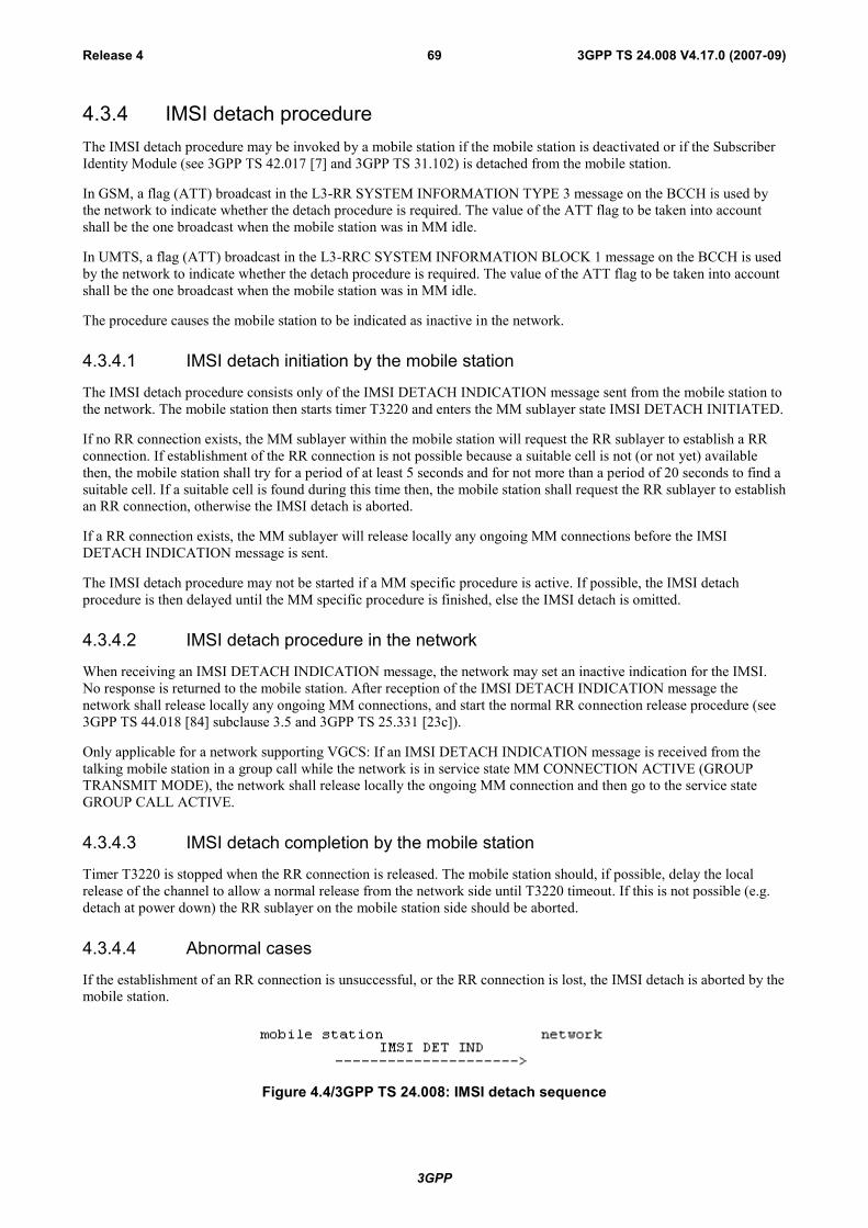
3GPP
3GPP TS 24.008 V4.17.0 (2007-09)Release 4 69
4.3.4 IMSI detach procedureThe IMSI detach procedure may be invoked by a mobile station if the mobile station is deactivated or if the SubscriberIdentity Module (see 3GPP TS 42.017 [7] and 3GPP TS 31.102) is detached from the mobile station.
In GSM, a flag (ATT) broadcast in the L3-RR SYSTEM INFORMATION TYPE 3 message on the BCCH is used bythe network to indicate whether the detach procedure is required. The value of the ATT flag to be taken into accountshall be the one broadcast when the mobile station was in MM idle.
In UMTS, a flag (ATT) broadcast in the L3-RRC SYSTEM INFORMATION BLOCK 1 message on the BCCH is usedby the network to indicate whether the detach procedure is required. The value of the ATT flag to be taken into accountshall be the one broadcast when the mobile station was in MM idle.
The procedure causes the mobile station to be indicated as inactive in the network.
4.3.4.1 IMSI detach initiation by the mobile station
The IMSI detach procedure consists only of the IMSI DETACH INDICATION message sent from the mobile station tothe network. The mobile station then starts timer T3220 and enters the MM sublayer state IMSI DETACH INITIATED.
If no RR connection exists, the MM sublayer within the mobile station will request the RR sublayer to establish a RRconnection. If establishment of the RR connection is not possible because a suitable cell is not (or not yet) availablethen, the mobile station shall try for a period of at least 5 seconds and for not more than a period of 20 seconds to find asuitable cell. If a suitable cell is found during this time then, the mobile station shall request the RR sublayer to establishan RR connection, otherwise the IMSI detach is aborted.
If a RR connection exists, the MM sublayer will release locally any ongoing MM connections before the IMSIDETACH INDICATION message is sent.
The IMSI detach procedure may not be started if a MM specific procedure is active. If possible, the IMSI detachprocedure is then delayed until the MM specific procedure is finished, else the IMSI detach is omitted.
4.3.4.2 IMSI detach procedure in the network
When receiving an IMSI DETACH INDICATION message, the network may set an inactive indication for the IMSI.No response is returned to the mobile station. After reception of the IMSI DETACH INDICATION message thenetwork shall release locally any ongoing MM connections, and start the normal RR connection release procedure (see3GPP TS 44.018 [84] subclause 3.5 and 3GPP TS 25.331 [23c]).
Only applicable for a network supporting VGCS: If an IMSI DETACH INDICATION message is received from thetalking mobile station in a group call while the network is in service state MM CONNECTION ACTIVE (GROUPTRANSMIT MODE), the network shall release locally the ongoing MM connection and then go to the service stateGROUP CALL ACTIVE.
4.3.4.3 IMSI detach completion by the mobile station
Timer T3220 is stopped when the RR connection is released. The mobile station should, if possible, delay the localrelease of the channel to allow a normal release from the network side until T3220 timeout. If this is not possible (e.g.detach at power down) the RR sublayer on the mobile station side should be aborted.
4.3.4.4 Abnormal cases
If the establishment of an RR connection is unsuccessful, or the RR connection is lost, the IMSI detach is aborted by themobile station.
Figure 4.4/3GPP TS 24.008: IMSI detach sequence
3GPP
3GPP TS 24.008 V4.17.0 (2007-09)Release 4 70
4.3.5 Abort procedureThe abort procedure may be invoked by the network to abort any on-going MM connection establishment or alreadyestablished MM connection. The mobile station shall treat ABORT message as compatible with current protocol stateonly if it is received when at least one MM connection exists or an MM connection is being established.
4.3.5.1 Abort procedure initiation by the network
The abort procedure consists only of the ABORT message sent from the network to the mobile station. Before thesending of the ABORT message the network shall locally release any ongoing MM connection. After the sending thenetwork may start the normal RR connection release procedure.
The Cause information element indicates the reason for the abortion. The following cause values may apply:
# 6: Illegal ME
#17: Network failure
4.3.5.2 Abort procedure in the mobile station
At the receipt of the ABORT message the mobile station shall abort any MM connection establishment or call re-establishment procedure and release all MM connections (if any). If cause value #6 is received the mobile station shalldelete any TMSI, LAI and ciphering key sequence number stored in the SIM, set the update status to ROAMING NOTALLOWED (and store it in the SIM according to subclause 4.1.2.2) and consider the SIM invalid until switch off or theSIM is removed. As a consequence the mobile station enters state MM IDLE, substate NO IMSI after the release of theRR connection.
The mobile station shall then wait for the network to release the RR connection - see subclause 4.5.3.1.
4.3.6 MM information procedureThe MM information message support is optional in the network.
The MM information procedure may be invoked by the network at any time during an RR connection.
4.3.6.1 MM information procedure initiation by the network
The MM information procedure consists only of the MM INFORMATION message sent from the network to themobile station. During an RR connection, the network shall send none, one, or more MM INFORMATION messages tothe mobile station. If more than one MM INFORMATION message is sent, the messages need not have the samecontent.
NOTE: The network may be able to select particular instants where it can send the MM INFORMATIONmessage without adding delay to, or interrupting, any CM layer transaction, e.g. immediately after theAUTHENTICATION REQUEST message.
4.3.6.2 MM information procedure in the mobile station
When the mobile station (supporting the MM information message) receives an MM INFORMATION message, it shallaccept the message and optionally use the contents to update appropriate information stored within the mobile station.
If the mobile station does not support the MM information message the mobile station shall ignore the contents of themessage and return an MM STATUS message with cause #97.
4.4 MM specific proceduresA MM specific procedure can only be started if no other MM specific procedure is running or no MM connection existsbetween the network and the mobile station. The end of the running MM specific procedure or the release of all MMconnections have to be awaited before a new MM specific procedure can be started.

3GPP
3GPP TS 24.008 V4.17.0 (2007-09)Release 4 71
During the lifetime of a MM specific procedure, if a MM connection establishment is requested by a CM entity, thisrequest will either be rejected or be delayed until the running MM specific procedure is terminated (this depends on theimplementation).
Any MM common procedure (except IMSI detach) may be initiated during a MM specific procedure.
Unless it has specific permission from the network (follow-on proceed) the mobile station side should await the releaseof the RR connection used for a MM specific procedure before a new MM specific procedure or MM connectionestablishment is started.
NOTE: The network side may use the same RR connection for MM connection management.
4.4.1 Location updating procedureThe location updating procedure is a general procedure which is used for the following purposes:
- normal location updating (described in this subclause);
- periodic updating (see subclause 4.4.2);
- IMSI attach (see subclause 4.4.3).
The normal location updating procedure is used to update the registration of the actual Location Area of a mobilestation in the network. The location updating type information element in the LOCATION UPDATING REQUESTmessage shall indicate normal location updating. The conditions under which the normal location updating procedure isused by a mobile station in the MM IDLE state are defined for each service state in subclause 4.2.2.
Only applicable for mobile stations supporting VGCS listening or VBS listening: A mobile station in RR group receivemode is in the MM IDLE state, substate RECEIVING GROUP CALL (NORMAL SERVICE) or RECEIVING GROUPCALL (LIMITED SERVICE). To perform a location updating, the MS in RR group receive mode shall leave the groupreceive mode, establish an independent dedicated RR connection to perform the location updating as described aboveand return to the RR group receive mode afterwards.
The normal location updating procedure shall also be started if the network indicates that the mobile station is unknownin the VLR as a response to MM connection establishment request.
To limit the number of location updating attempts made, where location updating is unsuccessful, an attempt counter isused. The attempt counter is reset when a mobile station is switched on or a SIM card is inserted.
Upon successful location updating the mobile station sets the update status to UPDATED in the SIM, and stores thereceived Location Area Identification in the SIM. The attempt counter shall be reset.
The detailed handling of the attempt counter is described in subclauses 4.4.4.6 to 4.4.4.9.
The Mobile Equipment shall contain a list of "forbidden location areas for roaming", as well as a list of "forbiddenlocation areas for regional provision of service". These lists shall be erased when the MS is switched off or when theSIM is removed, and periodically (with period in the range 12 to 24 hours). The location area identification received onthe BCCH that triggered the location updating request shall be added to the suitable list whenever a location updatereject message is received with the cause "Roaming not allowed in this location area" or with the cause "Location Areanot allowed". The lists shall accommodate each 10 or more location area identifications. When the list is full and a newentry has to be inserted, the oldest entry shall be deleted.
The Mobile Equipment shall store a list of "equivalent PLMNs". This list is replaced or deleted at the end of eachlocation update procedure, routing area update procedure and GPRS attach procedure. The stored list consists of a list ofequivalent PLMNs as downloaded by the network plus the PLMN code of the network that downloaded the list. Thestored list shall not be deleted when the MS is switched off. The stored list shall be deleted if the SIM is removed. Themaximum number of possible entries in the stored list is six.
The cell selection processes in the different states are described in 3GPP TS 43.022 [82] and 3GPP TS 45.008 [34].
The location updating procedure is always initiated by the mobile station.
3GPP
3GPP TS 24.008 V4.17.0 (2007-09)Release 4 72
4.4.2 Periodic updatingPeriodic updating may be used to notify periodically the availability of the mobile station to the network. Periodicupdating is performed by using the location updating procedure. The location updating type information element in theLOCATION UPDATING REQUEST message shall indicate periodic updating.
The procedure is controlled by the timer T3212 in the mobile station. If the timer is not already started, the timer isstarted each time the mobile station enters the MM IDLE substate NORMAL SERVICE or ATTEMPTing TOUPDATE. When the MS leaves the MM Idle State the timer T3212 shall continue running until explicitly stopped.
The timer is stopped (shall be set to its initial value for the next start) when:
- a LOCATION UPDATING ACCEPT or LOCATION UPDATING REJECT message is received;
- an AUTHENTICATION REJECT message is received;
- the first MM message is received, or security mode setting is completed in the case of MM connectionestablishment, except when the most recent service state is LIMITED SERVICE;
- the mobile station has responded to paging and thereafter has received the first correct layer 3 message exceptRR message;
- the mobile station is deactivated (i.e. equipment powered down or SIM removed).
When the timer T3212 expires, the location updating procedure is started and the timer shall be set to its initial value forthe next start. If the mobile station is in other state than MM Idle when the timer expires the location updatingprocedure is delayed until the MM Idle State is entered.
The conditions under which the periodic location updating procedure is used by a mobile station in the MM IDLE stateare defined for each service state in subclause 4.2.2.
If the mobile station is in service state NO CELL AVAILABLE, LIMITED SERVICE, PLMN SEARCH or PLMNSEARCH-NORMAL SERVICE when the timer expires the location updating procedure is delayed until this servicestate is left.
In GSM, the (periodic) location updating procedure is not started if the BCCH information at the time the procedure istriggered indicates that periodic location shall not be used. The timeout value is broadcasted in the L3-RR SYSTEMINFORMATION TYPE 3 message on the BCCH, in the Control channel description IE, see 3GPP TS 44.018 [84]subclause 10.5.2.11.
In UMTS, the (periodic) location updating procedure is not started if the information on BCCH or in the last receiveddedicated system information at the time the procedure is triggered indicates that periodic location shall not be used.The timeout value is broadcasted in the L3-RRC SYSTEM INFORMATION BLOCK 1 message on the BCCH, see3GPP TS 25.331 [23c].
The T3212 timeout value shall not be changed in the NO CELL AVAILABLE, LIMITED SERVICE, PLMN SEARCHand PLMN SEARCH-NORMAL SERVICE states.
When a change of the T3212 timeout value has to be taken into account and the timer is running (at change of theserving cell or, change of the broadcast value of T3212), the MS shall behave as follows:
Let t1 be the new T3212 timeout value and let t be the current timer value at the moment of the change to thenew T3212 timeout value; then the timer shall be restarted with the value t modulo t1.
When the mobile station is activated, or when a change of the T3212 timeout value has to be taken into account and thetimer is not running, the mobile station shall behave as follows:
Let t1 be the new T3212 timeout value, the new timer shall be started at a value randomly, uniformly drawnbetween 0 and t1.
4.4.3 IMSI attach procedureThe IMSI attach procedure is the complement of the IMSI detach procedure (see subclause 4.3.4). It is used to indicatethe IMSI as active in the network.

3GPP
3GPP TS 24.008 V4.17.0 (2007-09)Release 4 73
In GSM, a flag (ATT) is broadcast in the L3-RR SYSTEM INFORMATION TYPE 3 message. It indicates whether theattach and detach procedures are required to be used or not.
In UMTS, a flag (ATT) is broadcast in the L3-RRC SYSTEM INFORMATION BLOCK 1 message. It indicateswhether the attach and detach procedures are required to be used or not.
The IMSI attach procedure is invoked if the detach/attach procedures are required by the network and an IMSI isactivated in a mobile station (i.e. activation of a mobile station with plug-in SIM, insertion of a card in a card-operatedmobile station etc.) within coverage area from the network or a mobile station with an IMSI activated outside thecoverage area enters the coverage area. The IMSI attach procedure is used only if the update status is UPDATED and ifthe stored Location Area Identification is the same as the one which is actually broadcasted on the BCCH of the currentserving cell. Otherwise a normal location updating procedure (see subclause 4.4.1) is invoked independently of the ATTflag indication.
IMSI attach is performed by using the location updating procedure. The location updating type information element inthe LOCATION UPDATING REQUEST message shall in this case indicate IMSI attach.
4.4.4 Generic Location Updating procedure
4.4.4.1 Location updating initiation by the mobile station
Any timer used for triggering the location updating procedure (e.g. T3211, T3212) is stopped if running.
As no RR connection exists at the time when the location updating procedure has to be started, the MM sublayer withinthe mobile station will request the RR sublayer to establish a RR connection and enter state WAIT FOR RRCONNECTION (LOCATION UPDATE). The procedure for establishing an RR connection is described in3GPP TS 44.018 [84] subclause 3.3 and 3GPP TS 25.331 [23c].
The mobile station initiates the location updating procedure by sending a LOCATION UPDATING REQUESTmessage to the network, starts the timer T3210 and enters state LOCATION UPDATING INITIATED. The locationupdating type information element shall indicate what kind of updating is requested.
4.4.4.1a Network Request for Additional mobile station Capability Information
In GSM, the network may initiate the classmark interrogation procedure, for example, to obtain further information onthe mobile station's encryption capabilities.
4.4.4.2 Identification request from the network
The network may initiate the identification procedure, e.g. if the network is unable to get the IMSI based on the TMSIand LAI used as identification by the mobile station (see subclause 4.3.3).
4.4.4.3 Authentication by the network
The authentication procedure (see subclause 4.3.2) may be initiated by the network upon receipt of the LOCATIONUPDATING REQUEST message from the mobile station. (See the cases defined in 3GPP TS 42.009 [5]).
4.4.4.4 Security mode setting by the network
In GSM, the security mode setting procedure (see 3GPP TS 44.018 [84] subclause 3.4.7) may be initiated by thenetwork, e.g., if a new TMSI has to be allocated.
In UMTS, the security mode control procedure (see 3GPP TS 25.331 [23c]) may be initiated by the network, e.g., if anew TMSI has to be allocated.
4.4.4.5 Attempt Counter
To limit the number of location updating attempts made, where location updating is unsuccessful, an attempt counter isused. It counts the number of consecutive unsuccessful location update attempts.
3GPP
3GPP TS 24.008 V4.17.0 (2007-09)Release 4 74
The attempt counter is incremented when a location update procedure fails. The specific situations are specified insubclause 4.4.4.9.
The attempt counter is reset when:
- the mobile station is powered on;
- a SIM is inserted;
- location update is successfully completed;
- location update completed with cause #11, #12,#13 or #15 (see subclause 4.4.4.7).
and in case of service state ATTEMPTING to UPDATE:
- a MS detects that a new location area is entered;
- expiry of timer T3212;
- location update is triggered by CM sublayer requests.
The attempt counter is used when deciding whether to re-attempt a location update after timeout of timer T3211.
4.4.4.6 Location updating accepted by the network
If the location updating is accepted by the network a LOCATION UPDATING ACCEPT message is transferred to themobile station.
In case the identity confidentiality service is active (see subclauses 4.3.1 and 4.4.4.4), the TMSI reallocation may bepart of the location updating procedure. The TMSI allocated is then contained in the LOCATION UPDATINGACCEPT message together with the location area identifier LAI. The network shall in this case start the supervisiontimer T3250 as described in subclause 4.3.1.
If the network wishes to prolong the RR connection to allow the mobile station to initiate MM connection establishment(for example if the mobile station has indicated in the LOCATION UPDATING REQUEST that it has a follow-onrequest pending) the network shall send "follow on proceed" in the LOCATION UPDATING ACCEPT and start timerT3255.
The mobile station receiving a LOCATION UPDATING ACCEPT message shall store the received location areaidentification LAI, stop timer T3210, reset the attempt counter and set the update status in the SIM to UPDATED. If themessage contains an IMSI, the mobile station is not allocated any TMSI, and shall delete any TMSI in the SIMaccordingly. If the message contains a TMSI, the mobile station is allocated this TMSI, and shall store this TMSI in theSIM and a TMSI REALLOCATION COMPLETE shall be returned to the network. If neither IMSI nor TMSI isreceived in the LOCATION UPDATING ACCEPT message, the old TMSI if any available shall be kept.
If the LAI or PLMN identity contained in the LOCATION UPDATING ACCEPT message is a member of any of the"forbidden lists" then any such entries shall be deleted.
The network may also send a list of "equivalent PLMNs" in the LOCATION UPDATING ACCEPT message. Eachentry of the list contains a PLMN code (MCC+MNC). The mobile station shall store the list, as provided by thenetwork, except that any PLMN code that is already in the "forbidden PLMN list" shall be removed from the"equivalent PLMNs" list before it is stored by the mobile station. In addition the mobile station shall add to the storedlist the PLMN code of the network that sent the list. All PLMNs in the stored list shall be regarded as equivalent to eachother for PLMN selection, cell selection/re-selection and handover. The stored list in the mobile station shall bereplaced on each occurrence of the LOCATION UPDATING ACCEPT message. If no list is contained in the message,then the stored list in the mobile station shall be deleted. The list shall be stored in the mobile station while switched offso that it can be used for PLMN selection after switch on.
After that, the mobile station shall act according to the presence of the "Follow-on proceed" information element in theLOCATION UPDATING ACCEPT; if this element is present and the mobile station has a CM application requestpending, it shall send a CM SERVICE REQUEST to the network and proceed as in subclause 4.5.1.1. Otherwise, itshall start timer T3240 and enter state WAIT FOR NETWORK COMMAND.
Furthermore, the network may grant authorisation for the mobile station to use GSM-Cordless Telephony System (CTS)in the Location Area and its immediate neighbourhood. The mobile should memorise this permission in non-volatile

3GPP
3GPP TS 24.008 V4.17.0 (2007-09)Release 4 75
memory. If the "CTS permission" IE is not present in the message, the mobile is not authorised to use GSM-CTS, andshall accordingly delete any memorised permission.
NOTE: the interaction between CTS and GPRS procedures are not yet defined.
4.4.4.7 Location updating not accepted by the network
If the location updating cannot be accepted the network sends a LOCATION UPDATING REJECT message to themobile station. The mobile station receiving a LOCATION UPDATING REJECT message shall stop the timer T3210,store the reject cause, start T3240, enter state LOCATION UPDATING REJECTED await the release of the RRconnection triggered by the network, and for all causes except #12, #14 and #15 deletes the list of "equivalent PLMNs".
Upon the release of the RR connection the mobile station shall take the following actions depending on the stored rejectcause:
# 2: (IMSI unknown in HLR);
# 3: (Illegal MS); or
# 6: (Illegal ME).
The mobile station shall set the update status to ROAMING NOT ALLOWED (and store it in the SIM accordingto subclause 4.1.2.2), and delete any TMSI, stored LAI and ciphering key sequence number and shall considerthe SIM as invalid for non-GPRS services until switch-off or the SIM is removed.
# 11: (PLMN not allowed);
The mobile station shall delete any LAI, TMSI and ciphering key sequence number stored in the SIM, reset theattempt counter, set the update status to ROAMING NOT ALLOWED (and store it in the SIM according tosubclause 4.1.2.2). The mobile station shall store the PLMN identity in the "forbidden PLMN list".
The MS shall perform a PLMN selection when back to the MM IDLE state according to 3GPP TS 23.122 [14].
# 12: (Location Area not allowed);
The mobile station shall delete any LAI, TMSI and ciphering key sequence number stored in the SIM, reset theattempt counter, set the update status to ROAMING NOT ALLOWED (and store it in the SIM according tosubclause 4.1.2.2).
The mobile station shall store the LAI in the list of "forbidden location areas for regional provision of service".
The MS shall perform a cell selection when back to the MM IDLE state according to 3GPP TS 43.022 and3GPP TS 25.304.
# 13: (Roaming not allowed in this location area).
The mobile station shall reset the attempt counter, set the update status to ROAMING NOT ALLOWED (andstore it in the SIM according to clause 4.1.2.2).
The mobile station shall store the LAI in the list of "forbidden location areas for roaming".
The mobile station shall perform a PLMN selection instead of a cell selection when back to the MM IDLE stateaccording to 3GPP TS 23.122 [14].
# 15: (No Suitable Cells In Location Area).
The mobile station shall reset the attempt counter, set the update status to ROAMING NOT ALLOWED (andstore it in the SIM according to clause 4.1.2.2).
The mobile station shall store the LAI in the list of "forbidden location areas for roaming".
The mobile station shall search for a suitable cell in another location area in the same PLMN according to3GPP TS 43.022 and 3GPP TS 25.304.
Other values are considered as abnormal cases and the specification of the mobile station behaviour in those cases isgiven in subclause 4.4.4.9.

3GPP
3GPP TS 24.008 V4.17.0 (2007-09)Release 4 76
4.4.4.8 Release of RR connection after location updating
When the Location updating procedure is finished (see subclause s 4.4.4.6 and 4.4.4.7) the mobile station shall (exceptin the case where the mobile has a follow-on CM application request pending and has received the follow-on proceedindication, see subclause 4.4.4.6) set timer T3240 and enter the state WAIT FOR NETWORK COMMAND, expectingthe release of the RR connection. The network may decide to keep the RR connection for network initiatedestablishment of a MM connection, or to allow for mobile initiated MM connection establishment.
Any release of the RR connection shall be initiated by the network according to subclause 3.5 in 3GPP TS 44.018 [84],and 3GPP TS 25.331 [23c]. If the RR connection is not released within a given time controlled by the timer T3240, themobile station shall abort the RR connection. In both cases, either after a RR connection release triggered from thenetwork side or after a RR connection abort requested by the MS-side, the MS shall return to state MM IDLE.
At transition to state MM IDLE, substates NORMAL SERVICE or RECEIVING GROUP CALL (NORMALSERVICE) or ATTEMPTING TO UPDATE either timer T3212 or timer T3211 is started as described insubclause 4.4.4.9.
4.4.4.9 Abnormal cases on the mobile station side
The different abnormal cases that can be identified are the following:
a) Access barred because of access class control
The location updating procedure is not started. The mobile station stays in the current serving cell and applies normalcell reselection process. The procedure is started as soon as possible and if still necessary (when the barred state isended or because of a cell change).
b) The answer to random access is an IMMEDIATE ASSIGNMENT REJECT message (A/Gb mode only)
The location updating is not started. The mobile station stays in the chosen cell and applies normal cell selectionprocess. The waiting timer T3122 is reset when a cell change occurs. The procedure is started as soon as possible afterT3122 timeout if still necessary.
c) Random access failure (A/Gb mode only)
Timer T3213 is started. When it expires the procedure is attempted again if still necessary.
NOTE: As specified in 3GPP TS 45.008 [34], a cell reselection then takes place, with return to the cell inhibitedfor 5 seconds if there is at least one other suitable cell. Typically the selection process will take themobile station back to the cell where the random access failed after 5 seconds.
If at the expiry of timer T3213 a new cell has not been selected due to the lack of valid information (see 3GPP TS45.008 [34]), the mobile station may as an option delay the repeated attempt for up to 8 seconds to allow cell re-selection to take place. In this case the procedure is attempted as soon as a new cell has been selected or the mobilestation has concluded that no other cell can be selected.
If random access failure occurs for two successive random access attempts for location updating the mobile stationproceeds as specified below.
d) RR connection failure
The procedure is aborted and the mobile station proceeds as specified below.
e) T3210 timeout
The procedure is aborted, the RR connection is aborted and the MS proceeds as specified below.
f) RR release before the normal end of procedure
The procedure is aborted and the mobile station proceeds as specified below.
g) Location updating reject, other causes than those treated in subclause 4.4.4.7
The MS waits for release of the RR connection as specified in subclause 4.4.4.8, and then proceeds as specified below.
h) RR connection establishment failure (Iu mode only)

3GPP
3GPP TS 24.008 V4.17.0 (2007-09)Release 4 77
The procedure is aborted and the mobile station proceeds as specified below.
NOTE: Case h) covers all cases when the signalling connection cannot be established, including random accessfailure and access reject. As the RRC protocol has error specific retransmission mechanisms (see3GPP TS 25.331 [23c]), there is no need to distinguish between the different error cases within MM.
In cases d) to h) above and for repeated failures as defined in c) above the mobile station proceeds as follows. TimerT3210 is stopped if still running. The RR Connection is aborted in case of timer T3210 timeout. The attempt counter isincremented. The next actions depend on the Location Area Identities (stored and received from the BCCH of thecurrent serving cell) and the value of the attempt counter.
– the update status is UPDATED, and the stored LAI is equal to the one received on the BCCH from the currentserving cell and the attempt counter is smaller than 4:
The mobile station shall keep the update status to UPDATED, the MM IDLE sub-state after the RR connectionrelease is NORMAL SERVICE. The mobile station shall memorize the location updating type used in the locationupdating procedure. It shall start timer T3211 when the RR connection is released. When timer T3211 expires thelocation updating procedure is triggered again with the memorized location updating type;
– either the update status is different from UPDATED, or the stored LAI is different from the one received on theBCCH from the current serving cell, or the attempt counter is greater or equal to 4:
The mobile station shall delete any LAI, TMSI, ciphering key sequence number stored in the SIM, and list ofequivalent PLMNs, set the update status to NOT UPDATED and enter the MM IDLE sub-state ATTEMPTING TOUPDATE when the RR connection is released (See subclause 4.2.2.2 for the subsequent actions). If the attempt counteris smaller than 4, the mobile station shall memorize that timer T3211 is to be started when the RR connection isreleased, otherwise it shall memorize that timer T3212 is to be started when the RR connection is released.
4.4.4.10 Abnormal cases on the network side
a) RR connection failure
If a RR connection failure occurs during a common procedure integrated with the location updating procedure, thebehaviour of the network should be according to the description of that common procedure.
If a RR connection failure occurs when a common procedure does not exist, the location updating procedure towardsthe mobile station should be aborted.
b) protocol error
If the LOCATION UPDATING REQUEST message is received with a protocol error, the network should, if possible,return a LOCATION UPDATING REJECT message with one of the following Reject causes:
#96: Mandatory information element error
#99: Information element non-existent or not implemented
#100: Conditional IE error
#111: Protocol error, unspecified
Having sent the response, the network should start the channel release procedure (see subclause 3.5).
Figure 4.5/3GPP TS 24.008: Location updating sequence
3GPP
3GPP TS 24.008 V4.17.0 (2007-09)Release 4 78
4.4.5 Void
4.4.6 Void
4.5 Connection management sublayer service provisionThe concept of MM connection is introduced in this subclause. This concept is mainly a descriptive tool: Theestablishment of an MM connection by the network can be local (i.e. it is achieved by the transmission of the first CMlayer message and without the transmission of any MM layer messages) or can be achieved by the transmission of a CMSERVICE PROMPT message (eg. in the case of certain ring back services). The release of an MM connection by thenetwork or by the mobile station is always local, i.e. these purposes can be achieved without sending any MM messagesover the radio interface. (On the contrary, establishment of an MM connection by the mobile station requires thesending of MM messages over the radio interface. An exception is VGCS, where an MM connection will be establishedas result of an uplink access procedure (see subclause 3.7.2.1.1in 3GPP TS 44.018 [84]).)
The Mobility Management (MM) sublayer is providing connection management services to the different entities of theupper Connection management (CM) sublayer (see 3GPP TS 24.007 [20]). It offers to a CM entity the possibility to usean MM connection for the exchange of information with its peer entity. An MM connection is established and releasedon request from a CM entity. Different CM entities communicate with their peer entity using different MM connections.Several MM connections may be active at the same time.
An MM connection requires an RR connection. All simultaneous MM connections for a given mobile station use thesame RR connection.
In the following subclause s, the procedures for establishing, re-establishing, maintaining, and releasing an MMconnection are described, usually separately for the mobile station and the network side.
4.5.1 MM connection establishment
4.5.1.1 MM connection establishment initiated by the mobile station
Upon request of a CM entity to establish an MM connection the MM sublayer first decides whether to accept, delay, orreject this request:
- An MM connection establishment may only be initiated by the mobile station when the following conditions arefulfilled:
- Its update status is UPDATED.
- The MM sublayer is in one of the states MM IDLE, RR CONNECTION RELEASE NOT ALLOWED orMM connection active but not in MM connection active (Group call).
An exception from this general rule exists for emergency calls (see subclause 4.5.1.5). A further exception isdefined in the following clause.
- If an MM specific procedure is running at the time the request from the CM sublayer is received, and theLOCATION UPDATING REQUEST message has been sent, the request will either be rejected or delayed,depending on implementation, until the MM specific procedure is finished and, provided that the network hasnot sent a "follow-on proceed" indication, the RR connection is released. If the LOCATION UPDATINGREQUEST message has not been sent, the mobile station may include a "follow-on request" indicator in themessage. The mobile station shall then delay the request until the MM specific procedure is completed, when itmay be given the opportunity by the network to use the RR connection: see subclause 4.4.4.6.
In order to establish an MM connection, the mobile station proceeds as follows:
a) If no RR connection exists, the MM sublayer requests the RR sublayer to establish an RR connection and entersMM sublayer state WAIT FOR RR CONNECTION (MM CONNECTION). This request contains anestablishment cause and a CM SERVICE REQUEST message. When the establishment of an RR connection isindicated by the RR sublayer, the MM sublayer of the mobile station starts timer T3230, gives an indication tothe CM entity that requested the MM connection establishment, and enters MM sublayer state WAIT FOROUTGOING MM CONNECTION.

3GPP
3GPP TS 24.008 V4.17.0 (2007-09)Release 4 79
b) If an RR connection is available, the MM sublayer of the mobile station sends a CM SERVICE REQUESTmessage to the network, starts timer T3230, stops and resets timer T3241, gives an indication to the CM entitythat requested the MM connection establishment, and enters:
- MM sublayer state WAIT FOR OUTGOING MM CONNECTION, if no MM connection is active;
- MM sublayer state WAIT FOR ADDITIONAL OUTGOING MM CONNECTION, if at least one MMconnection is active;
- If an RR connection exists but the mobile station is in the state WAIT FOR NETWORK COMMAND thenany requests from the CM layer that are received will either be rejected or delayed until this state is left.
c) Only applicable for mobile stations supporting VGCS talking:
If a mobile station which is in the MM sublayer state MM IDLE, service state RECEIVING GROUP CALL(NORMAL SERVICE), receives a request from the GCC sublayer to perform an uplink access, the MM sublayerrequests the RR sublayer to perform an uplink access procedure and enters MM sublayer state WAIT FOR RRCONNECTION (GROUP TRANSMIT MODE).
When a successful uplink access is indicated by the RR sublayer, the MM sublayer of the mobile station gives anindication to the GCC sublayer and enters MM sublayer state MM CONNECTION ACTIVE (GROUPTRANSMIT MODE).
When an uplink access reject is indicated by the RR sublayer, the MM sublayer of the mobile station gives anindication to the GCC sublayer and enters the MM sublayer state MM IDLE, service state RECEIVING GROUPCALL (NORMAL SERVICE).
In the network, if an uplink access procedure is performed, the RR sublayer in the network provides anindication to the MM sublayer together with the mobile subscriber identity received in the TALKERINDICATION message. The network shall then enter the MM sublayer state MM CONNECTION ACTIVE(GROUP TRANSMIT MODE).
The CM SERVICE REQUEST message contains the:
- mobile identity according to subclause 10.5.1.4;
- mobile station classmark 2;
- ciphering key sequence number; and
- CM service type identifying the requested type of transaction (e.g. mobile originating call establishment,emergency call establishment, short message service, supplementary service activation, location services).
A MS supporting eMLPP may optionally include a priority level in the CM SERVICE REQUEST message.
A collision may occur when a CM layer message is received by the mobile station in MM sublayer state WAIT FOROUTGOING MM CONNECTION or in WAIT FOR ADDITIONAL OUTGOING MM CONNECTION. In this casethe MM sublayer in the MS shall establish a new MM connection for the incoming CM message as specified insubclause 4.5.1.3.
Upon receiving a CM SERVICE REQUEST message, the network shall analyse its content. The type of semanticanalysis may depend on other on going MM connection(s). Depending on the type of request and the current status ofthe RR connection, the network may start any of the MM common procedures and RR procedures.
In GSM, the network may initiate the classmark interrogation procedure, for example, to obtain further information onthe mobile station's encryption capabilities.
The identification procedure (see subclause 4.3.3) may be invoked for instance if a TMSI provided by the mobilestation is not recognized.
The network may invoke the authentication procedure (see subclause 4.3.2) depending on the CM service type.
In GSM, the network decides also if the ciphering mode setting procedure shall be invoked (see subclause 3.4.7 in3GPP TS 44.018 [84]).
3GPP
3GPP TS 24.008 V4.17.0 (2007-09)Release 4 80
In UMTS, the network decides also if the security mode control procedure shall be invoked (see 3GPP TS 25.331[23c]).
NOTE: If the CM_SERVICE_REQUEST message contains a priority level the network may use this to performqueuing and pre-emption as defined in 3GPP TS 23.067 [88].
In GSM, an indication from the RR sublayer that the ciphering mode setting procedure is completed, or reception of aCM SERVICE ACCEPT message, shall be treated as a service acceptance indication by the mobile station.
In UMTS, an indication from the RR sublayer that the security mode control procedure is completed, or reception of aCM SERVICE ACCEPT message, shall be treated as a service acceptance indication by the mobile station. Theprocedures in subclause 4.1.1.1.1 shall always have precedence over this subclause.
In UMTS, during a MM connection establishment for all services, except for emergency call (see subclause 4.1.1.1.1),the security mode control procedure with activation of integrity protection shall be invoked by the network unlessintegrity protection is already started (see subclause 4.1.1.1.1).
The MM connection establishment is completed, timer T3230 shall be stopped, the CM entity that requested the MMconnection shall be informed, and MM sublayer state MM CONNECTION ACTIVE is entered. The MM connection isconsidered to be active.
If the service request cannot be accepted, the network returns a CM SERVICE REJECT message to the mobile station.
The reject cause information element (see subclause 10.5.3.6 and annex G) indicates the reason for rejection. Thefollowing cause values may apply:
#4: IMSI unknown in VLR
#6: Illegal ME
#17: Network failure
#22: Congestion
#32: Service option not supported
#33: Requested service option not subscribed
#34: Service option temporarily out of order
If no other MM connection is active, the network may start the RR connection release (see subclause 3.5) when the CMSERVICE REJECT message is sent.
If a CM SERVICE REJECT message is received by the mobile station, timer T3230 shall be stopped, the requestingCM sublayer entity informed. Then the mobile station shall proceed as follows:
- If the cause value is not #4 or #6 the MM sublayer returns to the previous state (the state where the request wasreceived). Other MM connections shall not be affected by the CM SERVICE REJECT message.
- If cause value #4 is received, the mobile station aborts any MM connection, deletes any TMSI, LAI andciphering key sequence number in the SIM, changes the update status to NOT UPDATED (and stores it in theSIM according to subclause 4.1.2.2), and enters the MM sublayer state WAIT FOR NETWORK COMMAND. Ifsubsequently the RR connection is released or aborted, this will force the mobile station to initiate a normallocation updating). Whether the CM request shall be memorized during the location updating procedure, is achoice of implementation.
- If cause value #6 is received, the mobile station aborts any MM connection, deletes any TMSI, LAI andciphering key sequence number in the SIM, changes the update status to ROAMING NOT ALLOWED (andstores it in the SIM according to subclause 4.1.2.2), and enters the MM sublayer state WAIT FOR NETWORKCOMMAND. The mobile station shall consider the SIM as invalid for non-GPRS services until switch-off or theSIM is removed.

3GPP
3GPP TS 24.008 V4.17.0 (2007-09)Release 4 81
4.5.1.2 Abnormal cases
Mobile station side:
a) RR connection failure or IMSI deactivation
If an RR connection failure occurs or the IMSI is deactivated during the establishment of an MM connection, theMM connection establishment is aborted, timers T3230 is stopped, and an indication is given to the CM entitythat requested the MM connection establishment. This shall be treated as a rejection for establishment of the newMM connection, and the MM sublayer shall release all active MM connections.
b) T3230 expiry
If T3230 expires (i.e. no response is given but a RR connection is available) the MM connection establishment isaborted and the requesting CM sublayer is informed. If no other MM connection exists then the mobile stationshall proceed as described in subclause 4.5.3.1 for release of the RR connection. Otherwise the mobile stationshall return to the MM sublayer state where the request of an MM connection was received, i.e. to MM sublayerstate MM connection active. Other ongoing MM connections (if any) shall not be affected.
c) Reject cause values #95, #96, #97, #99, #100, #111 received
The same actions as on timer expiry shall be taken by the mobile station.
d) Random access failure or RR connection establishment failure
If the mobile station detects a random access failure or RR connection establishment failure during theestablishment of an MM connection, it aborts the MM connection establishment and gives an indication to theCM entity that requested the MM connection establishment.
NOTE: Further actions of the mobile station depend on the RR procedures and MM specific procedures duringwhich the abnormal situation has occurred and are described together with those procedures.
Network side:
a) RR connection failure
The actions to be taken upon RR connection failure within a MM common procedure are described together withthat procedure. A RR connection failure occurring outside such MM common procedures, shall trigger therelease of all active MM connections if any.
b) Invalid message or message content
Upon reception of an invalid initial message or a CM SERVICE REQUEST message with invalid content, a CMSERVICE REJECT message shall be returned with one of the following appropriate Reject cause indications:
# 95: Semantically incorrect message
# 96: Mandatory information element error
# 97: Message type non-existent or not implemented
# 99: Information element non-existent or not implemented
# 100: Conditional IE error
# 111: Protocol error, unspecified
When the CM SERVICE REJECT message has been sent, the network may start RR connection release if noother MM connections exist or if the abnormal condition also has influence on the other MM connections.
3GPP
3GPP TS 24.008 V4.17.0 (2007-09)Release 4 82
4.5.1.3 MM connection establishment initiated by the network
4.5.1.3.1 Mobile Terminating CM Activity
When a CM sublayer entity in the network requests the MM sublayer to establish a MM connection, the MM sublayerwill request the establishment of an RR connection to the RR sublayer if no RR connection to the desired mobile stationexists. The MM sublayer is informed when the paging procedure is finished (see 3GPP TS 44.018 [84] subclause 3.3.2and 3GPP TS 25.331 [23c]) and the mobile station shall enter the MM state WAIT FOR NETWORK COMMAND.
In GSM, when an RR connection is established (or if it already exists at the time the request is received), the MMsublayer may initiate any of the MM common procedures (except IMSI detach); it may request the RR sublayer toperform the RR classmark interrogation procedure, and/or the security mode setting procedure.
In UMTS, when an RR connection is established (or if it already exists at the time the request is received), the MMsublayer may initiate any of the MM common procedures (except IMSI detach); it may request the RR sublayer toperform the security mode control procedure.
When all MM and RR procedures are successfully completed which the network considers necessary, the MM sublayerwill inform the requesting mobile terminating CM sublayer entity on the success of the MM connection establishment.
If an RR connection already exists and no MM specific procedure is running, the network may also establish a newmobile terminating MM connection by sending a CM message with a new PD/TI combination.
If the MS receives the first CM message in the MM states WAIT FOR NETWORK COMMAND or RRCONNECTION RELEASE NOT ALLOWED, the MS shall stop and reset the timers T3240 and T3241 and shall enterthe MM state MM CONNECTION ACTIVE.
In GSM, if the establishment of an RR connection is unsuccessful, or if any of the MM common procedures or thesecurity mode setting fail, this is indicated to the CM layer with an appropriate error cause.
In UMTS, if the establishment of an RR connection is unsuccessful, or if any of the MM common procedures or thesecurity mode control fail, this is indicated to the CM layer with an appropriate error cause.
If an RR connection used for a MM specific procedure exists to the mobile station, the CM request may be rejected ordelayed depending on implementation. When the MM specific procedure has been completed, the network may use thesame RR connection for the delayed CM request.
Only applicable in case of VGCS talking:
In the MM CONNECTION ACTIVE (GROUP TRANSMIT MODE) the mobile station is in RR Group transmit mode.There shall be only one MM connection active.
When in MM CONNECTION ACTIVE (GROUP TRANSMIT MODE) state, the MM sublayer in the network shallreject the request for the establishment of another MM connection by any CM layer.
If the RR sublayer in the network indicates a request to perform a transfer of the mobile station from RR connectedmode to RR Group transmit mode which will result in a transition from MM CONNECTION ACTIVE state to MMCONNECTION ACTIVE (GROUP TRANSMIT MODE) state in the MM sublayer, the MM sublayer shall not allowthe transition if more than one MM connection is active with the mobile station.
4.5.1.3.2 Mobile Originating CM Activity $(CCBS)$
When a CM sublayer entity in the network requests the MM sublayer to establish a MM connection, the MM sublayerwill request the establishment of an RR connection to the RR sublayer if no RR connection to the desired mobile stationexists. The MM sublayer is informed when the paging procedure is finished (see 3GPP TS 44.018 [84] subclause 3.3.2and 3GPP TS 25.331 [23c]) and the mobile station shall enter the MM state WAIT FOR NETWORK COMMAND.
In GSM, when an RR connection is established (or if it already exists at the time the request is received), the MMsublayer may initiate any of the MM common procedures (except IMSI detach), it may request the RR sublayer toperform the RR classmark interrogation procedure and/or the security mode setting procedure.
In UMTS, when an RR connection is established (or if it already exists at the time the request is received), the MMsublayer may initiate any of the MM common procedures (except IMSI detach), it may request the RR sublayer toperform the security mode control procedure.
3GPP
3GPP TS 24.008 V4.17.0 (2007-09)Release 4 83
The network should use the information contained in the Mobile Station Classmark Type 2 IE on the mobile station'ssupport for "Network Initiated MO CM Connection Request" to determine whether to:
not start this procedure (eg if an RR connection already exists), or,
to continue this procedure, or,
to release the newly established RR connection.
In the case of a "Network Initiated MO CM Connection Request" the network shall use the established RR connectionto send a CM SERVICE PROMPT message to the mobile station.
If the mobile station supports "Network Initiated MO CM Connection Request", the MM sublayer of the MS gives anindication to the CM entity identified by the CM SERVICE PROMPT message and enters the MM sublayer statePROCESS CM SERVICE PROMPT. In the state PROCESS CM SERVICE PROMPT the MM sublayer waits foreither the rejection or confirmation of the recall by the identified CM entity. Any other requests from the CM entitiesshall either be rejected or delayed until this state is left.
When the identified CM entity informs the MM sublayer, that it has send the first CM message in order to start the CMrecall procedure the MM sublayer enters the state MM CONNECTION ACTIVE.
If the identified CM entity indicates that it will not perform the CM recall procedure and all MM connections arereleased by their CM entities the MS shall proceed according to subclause 4.5.3.1.
If the CM SERVICE PROMPT message is received by the MS in MM sublayer states WAIT FOR OUTGOING MMCONNECTION or in WAIT FOR ADDITIONAL OUTGOING MM CONNECTION then the mobile station shall sendan MM STATUS message with cause " Message not compatible with protocol state".
A mobile that does not support "Network Initiated MO CM Connection Request" shall return an MM STATUS messagewith cause #97 "message type non-existent or not implemented" to the network.
If the mobile station supports "Network Initiated MO CM Connection Request" but the identified CM entity in themobile station does not provide the associated support, then the mobile station shall send an MM STATUS messagewith cause "Service option not supported". In the case of a temporary CM problem (eg lack of transaction identifiers)then the mobile station shall send an MM STATUS message with cause "Service option temporarily out of order".
If an RR connection already exists and no MM specific procedure is running, the network may use it to send the CMSERVICE PROMPT message.
In GSM, if the establishment of an RR connection is unsuccessful, or if any of the MM common procedures or thesecurity mode setting fail, this is indicated to the CM layer in the network with an appropriate error cause.
In UMTS, if the establishment of an RR connection is unsuccessful, or if any of the MM common procedures or thesecurity mode control fail, this is indicated to the CM layer in the network with an appropriate error cause.
If an RR connection used for a MM specific procedure exists to the mobile station, the "Network Initiated MO CMConnection Request" may be rejected or delayed depending on implementation. When the MM specific procedure hasbeen completed, the network may use the same RR connection for the delayed "Network Initiated MO CM ConnectionRequest".
4.5.1.3.3 Paging response in UMTS (UMTS only)
The network may initiate the paging procedure for CS services when the MS is IMSI attached for CS services. Toinitiate the procedure, the MM entity requests the RR sublayer to initiate paging (see 3GPP TS 25.331 [23c] and3GPP TS 25.413) for CS services.
At reception of a paging message, the RR sublayer in the MS shall deliver a paging indication to the MM sublayer if thepaging was initiated by the MM entity in the network (see 3GPP TS 25.331 [23c]). The MS shall respond with thePAGING RESPONSE message defined in 3GPP TS 44.018 [84], subclause 9.1.25. For reasons of backwardcompatibility the paging response shall use the RR protocol discriminator.
If the MS receives a paging request for CS services during an ongoing MM procedure, and the MS has alreadyrequested the establishment of a radio connection, the MS shall ignore the paging request and the MS and the networkshall continue the MM procedure.
3GPP
3GPP TS 24.008 V4.17.0 (2007-09)Release 4 84
4.5.1.4 Abnormal cases
The behaviour upon abnormal events is described together with the relevant RR procedure or MM common procedure.
4.5.1.5 MM connection establishment for emergency calls
A MM connection for an emergency call may be established in all states of the mobility management sublayer whichallow MM connection establishment for a normal originating call. In addition, establishment may be attempted in allservice states where a cell is selected (see subclause 4.2.2) but not in the MM CONNECTION ACTIVE state (GROUPTRANSMIT MODE) state. However, as a network dependent option, a MM connection establishment for emergencycall may be rejected in some of the states.
When a user requests an emergency call establishment the mobile station will send a CM SERVICE REQUESTmessage to the network with a CM service type information element indicating emergency call establishment. If thenetwork does not accept the emergency call request, e.g., because IMEI was used as identification and this capability isnot supported by the network, the network will reject the request by returning a CM SERVICE REJECT message to themobile station.
The reject cause information element indicates the reason for rejection. The following cause values may apply:
#3 "Illegal MS"
#4 "IMSI unknown in VLR"
#5 "IMEI not accepted"
#6 "Illegal ME"
#17 "Network failure"
#22 "Congestion"
#32 "Service option not supported"
#34 "Service option temporarily out of order"
With the above defined exceptions, the procedures described for MM connection establishment in subclauses 4.5.1.1and 4.5.1.2 shall be followed.
NOTE: Normally, the mobile station will be identified by an IMSI or a TMSI. However, if none of theseidentifiers is available in the mobile station, then the mobile station shall use the IMEI for identificationpurposes. The network may in that case reject the request by returning a CM SERVICE REJECT messagewith reject cause: #5 "IMEI not accepted".
4.5.1.6 Call re-establishment
The re-establishment procedure allows a MS to resume a connection in progress after a radio link failure, possibly in anew cell and possibly in a new location area. The conditions in which to attempt call re-establishment or not depend onthe call control state, see subclause 5.5.4 and, whether or not a cell allowing call re-establishment has been found (asdescribed in 3GPP TS 45.008 [34]). MM connections are identified by their protocol discriminators and transactionidentifiers: these shall not be changed during call re-establishment.
The re-establishment takes place when a lower layer failure occurs and at least one MM connection is active (i.e.. themobile station's MM sublayer is either in state 6 "MM CONNECTION ACTIVE" or state 20 "WAIT FORADDITIONAL OUTGOING MM CONNECTION").
NOTE: During a re-establishment attempt the mobile station does not return to the MM IDLE state; thus nolocation updating is performed even if the mobile is not updated in the location area of the selected cell.
No call re-establishment shall be performed for voice group and broadcast calls.
4.5.1.6.1 Call re-establishment, initiation by the mobile station
NOTE: The network is unable to initiate call re-establishment.
3GPP
3GPP TS 24.008 V4.17.0 (2007-09)Release 4 85
If at least one request to re-establish an MM connection is received from a CM entity as a response to the indication thatthe MM connection is interrupted (see subclause 4.5.2.3.) the mobile station initiates the call re-establishmentprocedure. If several CM entities request re-establishment only one re-establishment procedure is initiated. If any CMentity requests re-establishment, then re-establishment of all transactions belonging to all Protocol Discriminators thatpermit Call Re-establishment shall be attempted.
Upon request of a CM entity to re-establish an MM connection the MM sublayer requests the RR sublayer to establishan RR connection and enters MM sublayer state WAIT FOR REESTABLISH. This request contains an establishmentcause and a CM RE-ESTABLISHMENT REQUEST message. When the establishment of an RR connection isindicated by the RR sublayer, the MM sublayer of the mobile station starts timer T3230, gives an indication to all CMentities that are being re-established, and remains in the MM sublayer state WAIT FOR REESTABLISH.
The CM RE-ESTABLISHMENT REQUEST message contains the
- mobile identity according to subclause 10.5.1.4;
- mobile station classmark 2;
- ciphering key sequence number.
NOTE: Whether or not a CM entity can request re-establishment depends upon the Protocol Discriminator. Thespecifications for Short Message Service (3GPP TS 24.011), Call Independent Supplementary Services(3GPP TS 24.010 [21]) and Location Services (3GPP TS 44.071 [23a]) do not currently specify any re-establishment procedures.
Upon receiving a CM RE-ESTABLISHMENT REQUEST message, the network shall analyse its content. Dependingon the type of request, the network may start any of the MM common procedures and RR procedures.
The network may initiate the classmark interrogation procedure, for example, to obtain further information on themobile station's encryption capabilities.
The identification procedure (see subclause 4.3.3) may be invoked.
The network may invoke the authentication procedure (see subclause 4.3.2).
In GSM, the network decides if the security mode setting procedure shall be invoked (see 3GPP TS 44.018 [84]subclause 3.4.7).
An indication from the RR sublayer that the security mode setting procedure is completed, or reception of a CMSERVICE ACCEPT message, shall be treated as a service acceptance indication by the mobile station.
In UMTS, the network decides if the security mode control procedure shall be invoked (see 3GPP TS 25.331 [23c]). Anindication from the RR sublayer that the security mode control procedure is completed, or reception of a CM SERVICEACCEPT message, shall be treated as a service acceptance indication by the mobile station.
The MM connection re-establishment is completed, timer T3230 shall be stopped, all CM entities associated with there-establishment shall be informed, and MM sublayer state MM CONNECTION ACTIVE is re-entered. All the MMconnections are considered to be active.
If the network cannot associate the re-establishment request with any existing call for that mobile station, a CMSERVICE REJECT message is returned with the reject cause:
#38 "call cannot be identified"
If call re-establishment cannot be performed for other reasons, a CM SERVICE REJECT is returned, the appropriatereject cause may be any of the following (see annex G):
# 4 "IMSI unknown in VLR";
# 6 "illegal ME";
#17 "network failure";
#22 "congestion";
#32 "service option not supported";
3GPP
3GPP TS 24.008 V4.17.0 (2007-09)Release 4 86
#34 "service option temporarily out of order".
Whatever the reject cause a mobile station receiving a CM SERVICE REJECT as a response to the CM RE-ESTABLISHMENT REQUEST shall stop T3230, release all MM connections and proceed as described insubclause 4.5.3.1. In addition:
- if cause value #4 is received, the mobile station deletes any TMSI, LAI and ciphering key sequence number inthe SIM, changes the update status to NOT UPDATED (and stores it in the SIM according to subclause 4.1.2.2),and enters the MM sublayer state WAIT FOR NETWORK COMMAND. If subsequently the RR connection isreleased or aborted, this will force the mobile station to initiate a normal location updating). The CM re-establishment request shall not be memorized during the location updating procedure.
- if cause value #6 is received, the mobile station deletes any TMSI, LAI and ciphering key sequence number inthe SIM, changes the update status to ROAMING NOT ALLOWED (and stores it in the SIM according tosubclause 4.1.2.2), and enters the MM sublayer state WAIT FOR NETWORK COMMAND. The MS shallconsider the SIM as invalid for non-GPRS services until switch-off or the SIM is removed.
4.5.1.6.2 Abnormal cases
Mobile station side:
a) Random access failure or RR connection establishment failure
If the mobile station detects a random access failure or RR connection establishment failure during the re-establishment of an MM connection, the re-establishment is aborted and all MM connections are released.
b) RR connection failure
If a RR connection failure occurs, timer T3230 is stopped, the re-establishment is aborted and all active MMconnections are released.
c) IMSI deactivation
If the IMSI deactivated during the re-establishment attempt then timer T3230 is stopped, the re-establishment isaborted and all MM connections are released.
d) T3230 expires
If T3230 expires (i.e. no response is given but a RR connection is available) the re-establishment is aborted, allactive MM connections are released and the mobile station proceeds as described in subclause 4.5.3.1.
e) Reject causes #96, #97, #99, #100, #111 received
The mobile station shall perform the same actions as if timer T3230 had expired.
Network side:
a) RR connection failure
If a RR connection failure occurs after receipt of the CM RE-ESTABLISHMENT REQUEST the network shallrelease all MM connections.
b) Invalid message content
Upon reception an invalid initial of message or a CM RE-ESTABLISHMENT REQUEST message with invalidcontent, a CM SERVICE REJECT message shall be returned with one of the following appropriate Reject causeindications:
#96: Mandatory information element error
#99: Information element non-existent or not implemented
#100: Conditional IE error
#111: Protocol error, unspecified
3GPP
3GPP TS 24.008 V4.17.0 (2007-09)Release 4 87
When the CM SERVICE REJECT message has been sent, the network shall release the RR connection.
4.5.1.7 Forced release during MO MM connection establishment
If the mobile station's CM layer initiated the MM connection establishment but the CM layer wishes to abort theestablishment prior to the completion of the establishment phase, the mobile station shall send a CM SERVICEABORT message any time after the completion of the RR connection and not after the first CM message (e.g. SETUP)is sent.
If the first CM message has already been sent, the normal release procedure defined by the appropriate CM protocolapplies and the CM SERVICE ABORT shall not be sent.
Sending of the CM SERVICE ABORT message is only allowed during the establishment of the first MM connection,where no other MM connection exists in parallel. If parallel MM connections exist already, a new connectionestablishment cannot be aborted and normal MM connection release according to subclause 4.5.3 applies after MMconnection establishment.
Upon transmission of the CM SERVICE ABORT message the mobile station shall set timer T3240 and enter the stateWAIT FOR NETWORK COMMAND, expecting the release of the RR connection.
Upon receipt of the CM SERVICE ABORT message the network shall abort ongoing processes, release the appropriateresources, and unless another MM connection establishment is pending, initiate a normal release of the RR connection.
If the RR connection is not released within a given time controlled by timer T3240, the mobile station shall abort theRR connection. In both cases, either after a RR connection release triggered from the network side or after a RRconnection abort requested by the mobile station side the mobile station shall return to state MM IDLE; the service statedepending upon the current update status as specified in subclause 4.2.3.
4.5.2 MM connection information transfer phaseAfter the MM connection has been established, it can be used by the CM sublayer entity for information transfer.According to the protocol architecture described in 3GPP TS 24.007 [20], each CM entity will have its own MMconnection. These different MM connections are identified by the protocol discriminator PD and, additionally, by thetransaction identifier TI.
All MM common procedures may be initiated at any time while MM connections are active. Except for Short MessageControl which uses a separate layer 2 low priority data link, no priority mechanism is defined between the CM, MMand RR sublayer messages.
4.5.2.1 Sending CM messages
A CM sublayer entity, after having been advised that a MM connection has been established, can request the transfer ofCM messages. The CM messages passed to the MM sublayer are then sent to the other side of the interface with the PDand TI set according to the source entity.
4.5.2.2 Receiving CM messages
Upon receiving a CM message, the MM sublayer will distribute it to the relevant CM entity according to the PD valueand TI value. However, if the received CM message is the first for the MM connection (identified by PD and TI), theMM sublayer will in addition indicate to the CM entity that a new MM connection has been established.
4.5.2.3 Abnormal cases
RR connection failure:
If the RR connection failure occurs during a RR or MM common procedure, the consequent actions aredescribed together with that procedure.
In other cases, the following applies:
- Mobile station:

3GPP
3GPP TS 24.008 V4.17.0 (2007-09)Release 4 88
The MM sublayer shall indicate to all CM entities associated with active MM connections that the MMconnection is interrupted, the subsequent action of the MM sublayer (call re-establishment, see 4.5.1.6, orlocal release) will then depend on the decisions by the CM entities.
- Network:
The MM sublayer shall locally release all active MM connections. As an option the network may delay therelease of all or some of the MM connections to allow the mobile station to initiate call re-establishment.
4.5.3 MM connection releaseAn established MM connection can be released by the local CM entity. The release of the CM connection will then bedone locally in the MM sublayer, i.e. no MM message are sent over the radio interface for this purpose.
4.5.3.1 Release of associated RR connection
If all MM connections are released by their CM entities, and no RRLP procedure (see 3GPP TS 44.031 [23b]) and noLCS procedure over RRC (see 3GPP TS 25.331 [23c]) is ongoing, the mobile station shall set timer T3240 and enter thestate WAIT FOR NETWORK COMMAND, expecting the release of the RR connection.
If all MM connections are released by their CM entities and an RRLP procedure or LCS procedure over RRC isongoing, the MS shall start the timer T3241 and enter the state RR CONNECTION RELEASE NOT ALLOWED.
If the MS is expecting the release of the RR connection in MM state WAIT FOR NETWORK COMMAND and anRRLP procedure or LCS procedure over RRC is started, the MS shall stop the timer T3240, start the timer T3241 andenter the state RR CONNECTION RELEASE NOT ALLOWED.
If the MS is in MM state RR CONNECTION RELEASE NOT ALLOWED and the ongoing RRLP procedure or LCSprocedure over RRC is finished, the MS shall stop the timer T3241, reset and start the timer T3240 and shall enter thestate WAIT FOR NETWORK COMMAND.
In the network, if the last MM connection is released by its user, the MM sublayer may decide to release the RRconnection. The RR connection may be maintained by the network, e.g. in order to establish another MM connection.
If the RR connection is not released within a given time controlled by the timer T3240 or T3241, the mobile stationshall abort the RR connection. In both cases, either after a RR connection release triggered from the network side orafter a RR connection abort requested by the MS-side, the MS shall return to MM IDLE state; the service statedepending upon the current update status as specified in subclause 4.2.3.
4.5.3.2 Uplink release in a voice group call
(Only applicable for mobile stations supporting VGCS talking:)
If a mobile station which is in the MM sublayer state MM CONNECTION ACTIVE (GROUP TRANSMIT MODE)receives a request from the GCC sublayer to perform an uplink release, the MM sublayer requests the RR sublayer toperform an uplink release procedure and enters the MM sublayer state RECEIVING GROUP CALL (NORMALSERVICE).
4.6 Receiving a MM STATUS message by a MM entity.If the MM entity of the mobile station receives a MM STATUS message no state transition and no specific action shallbe taken as seen from the radio interface, i.e. local actions are possible.
With the exceptions described for the responses to the CM SERVICE PROMPT message, the actions to be taken onreceiving a MM STATUS message in the network are an implementation dependent option.

3GPP
3GPP TS 24.008 V4.17.0 (2007-09)Release 4 89
4.7 Elementary mobility management procedures for GPRSservices
4.7.1 GeneralThis subclause describes the basic functions offered by the mobility management (GMM) sublayer at the radio interface(reference point Um/UU). The functionality is described in terms of timers and procedures. During GMM procedures,procedures of CM layer services via the PS domain, e.g. SM, SMS, and SS, are suspended.
4.7.1.1 Lower layer failure
The lower layers shall indicate a logical link failure or an RR sublayer failure or an RRC sublayer failure to the GMMsublayer. The failure indicates an error that cannot be corrected by the lower layers.
4.7.1.2 Ciphering of messages (GSM only)
If ciphering is to be applied on a GMM context, all GMM messages shall be ciphered except the following messages:
-- ATTACH REQUEST;
-- ATTACH REJECT;
-- AUTHENTICATION AND CIPHERING REQUEST;
-- AUTHENTICATION AND CIPHERING RESPONSE;
-- AUTHENTICATION AND CIPHERING FAILURE;
-- AUTHENTICATION AND CIPHERING REJECT;
-- IDENTITY REQUEST;
-- IDENTITY RESPONSE;
-- ROUTING AREA UPDATE REQUEST; and
-- ROUTING AREA UPDATE REJECT.
4.7.1.3 P-TMSI signature
The network may assign a P-TMSI signature to an MS in an attach, routing area update, or P-TMSI reallocationprocedure. Only in combination with a valid P-TMSI, this P-TMSI signature is used by the MS for authentication andidentification purposes in the subsequent attach, routing area update or detach procedure. If the MS has no valid P-TMSI it shall not use the P-TMSI signature in the subsequent attach, routing area update or detach procedure. Uponsuccessful completion of the subsequent attach or routing area update procedure, the used P-TMSI signature shall bedeleted. Upon completion of the detach procedure, the used P-TMSI signature shall be deleted.
4.7.1.4 Radio resource sublayer address handling
In GSM, while a packet TMSI (P-TMSI) is used in the GMM sublayer for identification of an MS, a temporary logicallink identity (TLLI) is used for addressing purposes at the RR sublayer..
In UMTS a Radio Network Temporary Identity (RNTI) identifies a UMTS user between the MS and the UTRAN. Therelationship between RNTI and IMSI is known only in the MS and in the UTRAN, see 3GPP TS 25.301[10].

3GPP
3GPP TS 24.008 V4.17.0 (2007-09)Release 4 90
4.7.1.4.1 Radio resource sublayer address handling (GSM only)
This subclause describes how the RR addressing is managed by GMM. For the detailed coding of the different TLLItypes and how a TLLI can be derived from a P-TMSI, see 3GPP TS 23.003 [10].
Two cases can be distinguished:
- a valid P-TMSI is available in the MS; or
- no valid P-TMSI is available in the MS.
i) valid P-TMSI available
If the MS has stored a valid P-TMSI, the MS shall derive a foreign TLLI from that P-TMSI and shall use it fortransmission of the:
- ATTACH REQUEST message of any GPRS combined/non-combined attach procedure; other GMMmessages sent during this procedure shall be transmitted using the same foreign TLLI until the ATTACHACCEPT message or the ATTACH REJECT message is received; and
- ROUTING AREA UPDATE REQUEST message of a combined/non-combined RAU procedure if the MShas entered a new routing area, or if the GPRS update status is not equal to GU1 UPDATED. Other GMMmessages sent during this procedure shall be transmitted using the same foreign TLLI, until the ROUTINGAREA UPDATE ACCEPT message or the ROUTING AREA UPDATE REJECT message is received.
After a successful GPRS attach or routing area update procedure, independent whether a new P-TMSI isassigned, if the MS has stored a valid P-TMSI then the MS shall derive a local TLLI from the stored P-TMSIand shall use it for addressing at lower layers.
NOTE: Although the MS derives a local TLLI for addressing at lower layers, the network should not assume thatit will receive only LLC frames using a local TLLI. Immediately after the successful GPRS attach orrouting area update procedure, the network must be prepared to continue accepting LLC frames from theMS still using the foreign TLLI.
ii) no valid P-TMSI available
When the MS has not stored a valid P-TMSI, i.e. the MS is not attached to GPRS, the MS shall use a randomlyselected random TLLI for transmission of the:
- ATTACH REQUEST message of any combined/non-combined GPRS attach procedure.
The same randomly selected random TLLI value shall be used for all message retransmission attempts and forthe cell updates within one attach attempt.
Upon receipt of an ATTACH REQUEST message, the network shall assign a P-TMSI to the MS. The networkderives a local TLLI from the assigned P-TMSI, and transmits the assigned P-TMSI to the MS.
Upon receipt of the assigned P-TMSI, the MS shall derive the local TLLI from this P-TMSI and shall use it foraddressing at lower layers.
NOTE: Although the MS derives a local TLLI for addressing at lower layers, the network should not assume thatit will receive only LLC frames using a local TLLI. Immediately after the successful GPRS attach, thenetwork must be prepared to continue accepting LLC frames from the MS still using the random TLLI.
In both cases, the MS shall acknowledge the reception of the assigned P-TMSI to the network. After receipt of theacknowledgement, the network shall use the local TLLI for addressing at lower layers.
4.7.1.5 P-TMSI handling
4.7.1.5.1 P-TMSI handling in GSM
If a new P-TMSI is assigned by the network the MS and the network shall handle the old and the new P-TMSI asfollows:

3GPP
3GPP TS 24.008 V4.17.0 (2007-09)Release 4 91
Upon receipt of a GMM message containing a new P-TMSI the MS shall consider the new P-TMSI and new RAI andalso the old P-TMSI and old RAI as valid in order to react to paging requests and downlink transmission of LLCframes. For uplink transmission of LLC frames the new P-TMSI shall be used.
The MS shall consider the old P-TMSI and old RAI as invalid as soon as an LLC frame is received with the local TLLIderived from the new P-TMSI.
Upon the transmission of a GMM message containing a new P-TMSI the network shall consider the new P-TMSI andnew RAI and also the old P-TMSI and old RAI as valid in order to be able to receive LLC frames from the MS.
The network shall consider the old P-TMSI and old RAI as invalid as soon as an LLC frame is received with the localTLLI derived from the new P-TMSI.
4.7.1.5.2 P-TMSI handling in UMTS
If a new P-TMSI is assigned by the network the MS and the network shall handle the old and the new P-TMSI asfollows:
Upon receipt of a GMM message containing a new P-TMSI the MS shall consider the new P-TMSI and new RAI asvalid. Old P-TMSI and old RAI are regarded as invalid.
The network shall consider the old P-TMSI and old RAI as invalid as soon as an acknowledge message (e.g. ATTACHCOMPLETE, ROUTING AREA UPDATE COMPLETE and P-TMSI REALLOCATION COMPLETE) is received.
4.7.1.6 Change of network mode of operation
In the following tables below the abbreviations 'GSM I', 'GSM II' and 'GSM III' are used for network operation mode I,II and III in GSM.
In the following tables below the abbreviations 'UMTS I' and 'UMTS II' are used for network operation modes I and IIin UMTS.
4.7.1.6.1 Change of network mode of operation in GSM (GSM only)
Whenever an MS moves to a new RA, the procedures executed by the MS depend on the network mode of operation inthe old and new routing area.
In case the MS is in state GMM-REGISTERED or GMM-ROUTING-AREA-UPDATING-INITIATED and is inoperation mode:
a) A or B (with the exceptions in b and c below), the MS shall execute:
Table 4.7.1.6.1/3GPP TS 24.008: Mode A or B
Network operationmode change
Procedure to execute
I II or I III Normal Location Update(*),followed by a Normal Routing Area Update
II III or III II Normal Location Update (see subclause 4.2.2),followed by a Normal Routing Area Update
II I or III I Combined Routing Area Update with IMSI attach

3GPP
3GPP TS 24.008 V4.17.0 (2007-09)Release 4 92
b) B which reverts to operation mode C in network operation mode III, the MS shall execute:
Table 4.7.1.6.2/3GPP TS 24.008: Mode B which reverts into mode C in network operation mode III
Network operationmode change
Procedure to execute
I II Normal Location Update(*),followed by a Normal Routing Area Update
I III or II III IMSI Detach (see subclause 4.3.4),followed by a Normal Routing Area Update
II I or III I Combined Routing Area Update with IMSI attachIII II IMSI attach (see subclause 4.4.3),
followed by a Normal Routing Area Update
c) B which reverts to IMSI attached for CS services only in network operation mode III, the MS shall execute:
Table 4.7.1.6.3/3GPP TS 24.008: Mode B which reverts into IMSI attached for CS services only innetwork operation mode III
Network operationmode change
Procedure to execute
I II Normal Location Update(*),followed by a Normal Routing Area Update
I III Normal Location Update(*),followed by a GPRS Detach with type indicating "GPRS Detach"
II III Normal Location Update (see subclause 4.2.2),followed by a GPRS Detach with detach type indicating "GPRS Detach"
II I Combined Routing Area Update with IMSI attachIII I Combined GPRS AttachIII II Normal Location Update (see subclause 4.2.2),
followed by a Normal GPRS Attach(*) Intended to remove the Gs association in the MSC/VLR.
Further details are implementation issues.
4.7.1.6.2 Change of network mode of operation in UMTS (UMTS only)
Whenever an MS moves to a new RA, the procedures executed by the MS depend on the network mode of operation inthe old and new routing area.
In case the MS is in state GMM-REGISTERED or GMM-ROUTING-AREA-UPDATING-INITIATED and is inoperation mode A, the MS shall execute:
Table 4.7.1.6.4/3GPP TS 24.008: Mode A
Network operationmode change
Procedure to execute
I II Normal Location Update(*),followed by a Normal Routing Area Update
II I Combined Routing Area Update with IMSI attach
(*) Intended to remove the Gs association in the MSC/VLR.
Further details are implementation issues.
4.7.1.6.3 Change of network mode of operation at UMTS to GSM inter-system change
Whenever an MS moves to a new RA supporting the GSM radio interface, the procedures executed by the MS dependon the network mode of operation in the old and new routing area.
In case the MS is in state GMM-REGISTERED or GMM-ROUTING-AREA-UPDATING-INITIATED and is inoperation mode:
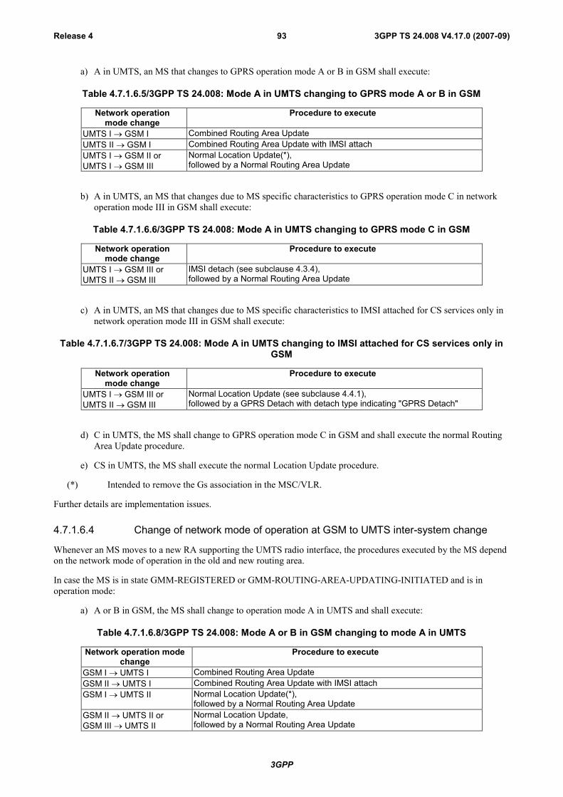
3GPP
3GPP TS 24.008 V4.17.0 (2007-09)Release 4 93
a) A in UMTS, an MS that changes to GPRS operation mode A or B in GSM shall execute:
Table 4.7.1.6.5/3GPP TS 24.008: Mode A in UMTS changing to GPRS mode A or B in GSM
Network operationmode change
Procedure to execute
UMTS I GSM I Combined Routing Area UpdateUMTS II GSM I Combined Routing Area Update with IMSI attachUMTS I GSM II orUMTS I GSM III
Normal Location Update(*),followed by a Normal Routing Area Update
b) A in UMTS, an MS that changes due to MS specific characteristics to GPRS operation mode C in networkoperation mode III in GSM shall execute:
Table 4.7.1.6.6/3GPP TS 24.008: Mode A in UMTS changing to GPRS mode C in GSM
Network operationmode change
Procedure to execute
UMTS I GSM III orUMTS II GSM III
IMSI detach (see subclause 4.3.4),followed by a Normal Routing Area Update
c) A in UMTS, an MS that changes due to MS specific characteristics to IMSI attached for CS services only innetwork operation mode III in GSM shall execute:
Table 4.7.1.6.7/3GPP TS 24.008: Mode A in UMTS changing to IMSI attached for CS services only inGSM
Network operationmode change
Procedure to execute
UMTS I GSM III orUMTS II GSM III
Normal Location Update (see subclause 4.4.1),followed by a GPRS Detach with detach type indicating "GPRS Detach"
d) C in UMTS, the MS shall change to GPRS operation mode C in GSM and shall execute the normal RoutingArea Update procedure.
e) CS in UMTS, the MS shall execute the normal Location Update procedure.
(*) Intended to remove the Gs association in the MSC/VLR.
Further details are implementation issues.
4.7.1.6.4 Change of network mode of operation at GSM to UMTS inter-system change
Whenever an MS moves to a new RA supporting the UMTS radio interface, the procedures executed by the MS dependon the network mode of operation in the old and new routing area.
In case the MS is in state GMM-REGISTERED or GMM-ROUTING-AREA-UPDATING-INITIATED and is inoperation mode:
a) A or B in GSM, the MS shall change to operation mode A in UMTS and shall execute:
Table 4.7.1.6.8/3GPP TS 24.008: Mode A or B in GSM changing to mode A in UMTS
Network operation modechange
Procedure to execute
GSM I UMTS I Combined Routing Area UpdateGSM II UMTS I Combined Routing Area Update with IMSI attachGSM I UMTS II Normal Location Update(*),
followed by a Normal Routing Area UpdateGSM II UMTS II orGSM III UMTS II
Normal Location Update,followed by a Normal Routing Area Update
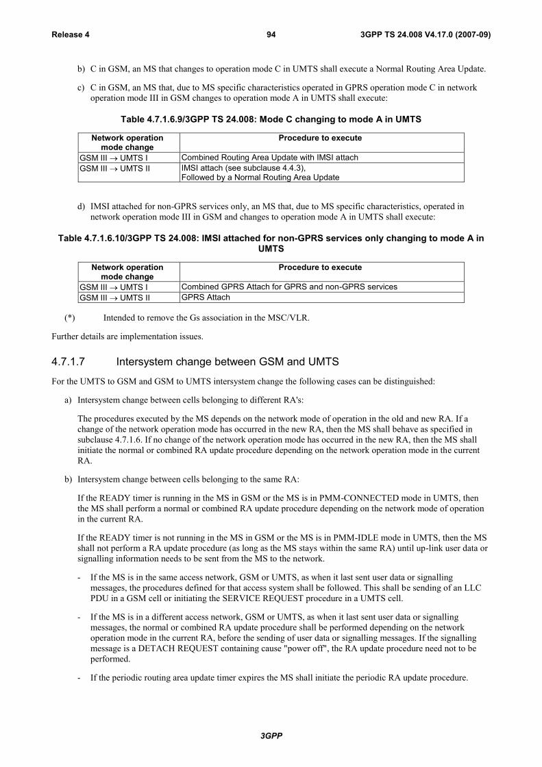
3GPP
3GPP TS 24.008 V4.17.0 (2007-09)Release 4 94
b) C in GSM, an MS that changes to operation mode C in UMTS shall execute a Normal Routing Area Update.
c) C in GSM, an MS that, due to MS specific characteristics operated in GPRS operation mode C in networkoperation mode III in GSM changes to operation mode A in UMTS shall execute:
Table 4.7.1.6.9/3GPP TS 24.008: Mode C changing to mode A in UMTS
Network operationmode change
Procedure to execute
GSM III UMTS I Combined Routing Area Update with IMSI attachGSM III UMTS II IMSI attach (see subclause 4.4.3),
Followed by a Normal Routing Area Update
d) IMSI attached for non-GPRS services only, an MS that, due to MS specific characteristics, operated innetwork operation mode III in GSM and changes to operation mode A in UMTS shall execute:
Table 4.7.1.6.10/3GPP TS 24.008: IMSI attached for non-GPRS services only changing to mode A inUMTS
Network operationmode change
Procedure to execute
GSM III UMTS I Combined GPRS Attach for GPRS and non-GPRS servicesGSM III UMTS II GPRS Attach
(*) Intended to remove the Gs association in the MSC/VLR.
Further details are implementation issues.
4.7.1.7 Intersystem change between GSM and UMTS
For the UMTS to GSM and GSM to UMTS intersystem change the following cases can be distinguished:
a) Intersystem change between cells belonging to different RA's:
The procedures executed by the MS depends on the network mode of operation in the old and new RA. If achange of the network operation mode has occurred in the new RA, then the MS shall behave as specified insubclause 4.7.1.6. If no change of the network operation mode has occurred in the new RA, then the MS shallinitiate the normal or combined RA update procedure depending on the network operation mode in the currentRA.
b) Intersystem change between cells belonging to the same RA:
If the READY timer is running in the MS in GSM or the MS is in PMM-CONNECTED mode in UMTS, thenthe MS shall perform a normal or combined RA update procedure depending on the network mode of operationin the current RA.
If the READY timer is not running in the MS in GSM or the MS is in PMM-IDLE mode in UMTS, then the MSshall not perform a RA update procedure (as long as the MS stays within the same RA) until up-link user data orsignalling information needs to be sent from the MS to the network.
- If the MS is in the same access network, GSM or UMTS, as when it last sent user data or signallingmessages, the procedures defined for that access system shall be followed. This shall be sending of an LLCPDU in a GSM cell or initiating the SERVICE REQUEST procedure in a UMTS cell.
- If the MS is in a different access network, GSM or UMTS, as when it last sent user data or signallingmessages, the normal or combined RA update procedure shall be performed depending on the networkoperation mode in the current RA, before the sending of user data or signalling messages. If the signallingmessage is a DETACH REQUEST containing cause "power off", the RA update procedure need not to beperformed.
- If the periodic routing area update timer expires the MS shall initiate the periodic RA update procedure.

3GPP
3GPP TS 24.008 V4.17.0 (2007-09)Release 4 95
If the READY timer is not running in the network in GSM or the network is in PMM-IDLE mode in UMTS,then the network shall page the MS if down-link user data or signalling information needs to be sent from thenetwork to the MS. This shall include both GSM and UMTS cells.
- If the MS receives the paging indication in the same access network, GSM or UMTS, as when it last sent userdata or signalling information, the MS shall send any LLC PDU in a GSM cell or shall initiate the SERVICEREQUEST procedure indicating service type "paging response" in a UMTS cell.
- If the MS receives the paging indication in a different access network, GSM or UMTS, as when it last sentuser data or signalling information, the normal or combined RA update procedure shall be performeddepending on the network operation mode in the current RA.
c) Intersystem handover from GSM to UMTS during a CS connection:
After the successful completion of the handover from an GSM cell to an UMTS cell, an MS which hasperformed the GPRS suspension procedure in Gb mode (see 3GPP TS 44.018 [84]) (i.e. an MS in MS operationmode B or an DTM MS in a GSM cell that does not support DTM) shall perform a normal RA update procedurein the UMTS cell in order to resume the GPRS services in the network, before sending any other signallingmessages or user data.
4.7.1.8 List of forbidden PLMNs for GPRS service
The Mobile Equipment shall contain a list of "forbidden PLMNs for GPRS service". This lists shall be erased when theMS is switched off or when the SIM is removed. The PLMN identification received on the BCCH shall be added to thelist whenever a GPRS attach, GPRS detach or routing area update is rejected by the network with the cause "GPRSservices not allowed in this PLMN". The maximum number of possible entries in this list is implementation dependant,but must be at least one entry. When the list is full and a new entry has to be inserted, the oldest entry shall be deleted.
4.7.2 GPRS Mobility management timers and UMTS PS signallingconnection control
4.7.2.1 READY timer behaviour
4.7.2.1.1 READY timer behaviour (GSM only)
The READY timer, T3314 is used in the MS and in the network per each assigned P-TMSI to control the cell updatingprocedure.
When the READY timer is running or has been deactivated the MS shall perform cell update each time a new cell isselected (see 3GPP TS 43.022 [82]). If a routing area border is crossed, a routing area updating procedure shall beperformed instead of a cell update.
When the READY timer has expired the MS shall:
- perform the routing area updating procedure when a routing area border is crossed;
- not perform a cell update when a new cell is selected.
All other GMM procedures are not affected by the READY timer.
The READY timer is started:
- in the MS when the GMM entity receives an indication from lower layers that an LLC frame other than LLCNULL frame has been transmitted on the radio interface; and
- in the network when the GMM entity receives an indication from lower layers that an LLC frame other than LLCNULL frame has been successfully received by the network.
Within GMM signalling procedures the network includes a "force to standby" information element, in order to indicatewhether or not the READY timer shall be stopped when returning to the GMM-REGISTERED state. If the "force tostandby" information element is received within more than one message during a ongoing GMM specific procedure, the

3GPP
3GPP TS 24.008 V4.17.0 (2007-09)Release 4 96
last one received shall apply. If the READY timer is deactivated and the network indicates "force to standby" with the"force to standby" information element, this shall not cause a modification of the READY timer.
The READY timer is not affected by state transitions to and from the GMM-REGISTERED.SUSPENDED sub-state.
The value of the READY timer may be negotiated between the MS and the network using the GPRS attach or GPRSrouting area updating procedure.
- If the MS wishes to indicate its preference for a READY timer value it shall include the preferred values into theATTACH REQUEST and/or ROUTING AREA UPDATE REQUEST messages. The preferred values may besmaller, equal to or greater than the default values or may be equal to the value requesting the READY Timerfunction to be deactivated.
- Regardless of whether or not a timer value has been received by the network in the ATTACH REQUEST orROUTING AREA UPDATE REQUEST messages, the network may include a timer value for the READY timer(different or not from the default value) into the ATTACH ACCEPT or ROUTING AREA UPDATE ACCEPTmessages, respectively. If the READY Timer value was included, it shall be applied for the GMM context by thenetwork and by the MS.
- When the MS proposes a READY Timer value and the Network does not include any READY Timer Value inits answer, then the value proposed by the MS shall be applied for the GMM context by the Network and by theMS.
- When neither the MS nor the Network proposes a READY Timer value into the ATTACH ACCEPT orROUTING AREA UPDATE ACCEPT message, then the default value shall be used.
If the negotiated READY timer value indicates that the ready timer function is deactivated, the READY timer shallalways run without expiry. If the negotiated READY timer value indicates that the ready timer function is deactivated,and within the same procedure the network indicates "force to standby" with the "force to standby" informationelement, the READY timer shall always run without expiry. If the negotiated READY timer value is set to zero,READY timer shall be stopped immediately.
To account for the LLC frame uplink transmission delay, the READY timer value should be slightly shorter in thenetwork than in the MS. This is a network implementation issue.
If a new READY timer value is negotiated, the MS shall upon the reception of the ATTACH ACCEPT or ROUTINGAREA UPDATE ACCEPT message perform a initial cell update (either by transmitting a LLC frame or, if required, aATTACH COMPLETE or ROUTING AREA UPDATE COMPLETE message), in order to apply the new READYtimer value immediately. If both the network and the MS supports the Cell Notification, the initial cell update shall useany LLC frame except the LLC NULL frame. If the new READY timer value is set to zero or if the network indicates"force to standby" with the "force to standby" IE, the initial cell update should not be done.
4.7.2.1.2 Handling of READY timer in UMTS (UMTS only)
The READY timer is not applicable for UMTS.
An MS may indicate a READY timer value to the network in the ATTACH REQUEST and the ROUTING AREAUPDATE REQUEST messages.
If a READY timer value is received by an MS capable of both UMTS and GSM in the ATTACH ACCEPT or theROUTING AREA UPDATE ACCEPT messages, then the received value shall be stored by the MS in order to be usedat an intersystem change from UMTS to GSM.
4.7.2.2 Periodic routing area updating
Periodic routing area updating is used to periodically notify the availability of the MS to the network. The procedure iscontrolled in the MS by the periodic RA update timer, T3312. The value of timer T3312 is sent by the network to theMS in the messages ATTACH ACCEPT and ROUTING AREA UPDATE ACCEPT. The value of the timer T3312shall be unique within a RA.
In GSM, the timer T3312 is reset and started with its initial value, when the READY timer is stopped or expires. Thetimer T3312 is stopped and shall be set to its initial value for the next start when the READY timer is started. If after aREADY timer negotiation the READY timer value is set to zero, timer T3312 is reset and started with its initial value.

3GPP
3GPP TS 24.008 V4.17.0 (2007-09)Release 4 97
If the initial READY timer value is zero, the timer T3312 is reset and started with its initial value, when the ROUTINGAREA UPDATE REQUEST message is transmitted.
In UMTS, the timer T3312 is reset and started with its initial value, when the MS goes from PMM-CONNECTED toPMM-IDLE mode. The timer T3312 is stopped when the MS enters PMM-CONNECTED mode.
When timer T3312 expires, the periodic routing area updating procedure shall be started and the timer shall be set to itsinitial value for the next start.
If the MS is in other state than GMM-REGISTERED.NORMAL-SERVICE when the timer expires the periodic routingarea updating procedure is delayed until the MS returns to GMM-REGISTERED.NORMAL-SERVICE.
In GSM, if the MS in MS operation mode B is in the state GMM-REGISTERED.SUSPENDED when the timer expiresthe periodic routing area updating procedure is delayed until the state is left.
The network supervises the periodic routing area updating procedure by means of the Mobile Reachable timer. TheMobile Reachable timer shall be longer than the periodic RA update timer. When the Mobile Reachable timer expires,typically the network stops sending paging messages to the mobile and may take other appropriate actions.
In GSM, the Mobile Reachable timer is reset and started with its initial value, when the READY timer is stopped orexpires. The Mobile Reachable timer is stopped and shall be set to its initial value for the next start when the READYtimer is started.
In GSM, if after a READY timer negotiation the READY timer value is set to zero the Mobile Reachable timer is resetand started with its initial value. If the initial READY timer value is zero, the Mobile Reachable is reset and started withits initial value, when the ROUTING AREA UPDATE REQUEST message is received.
In UMTS, the Mobile Reachable timer is reset and started with its initial value, when the MS goes from PMM-CONNECTED to PMM-IDLE mode. The Mobile Reachable timer is stopped when the MS enters PMM-CONNECTEDmode.
If the MS is both IMSI attached for GPRS and non-GPRS services, and if the MS lost coverage of the registered PLMNand timer T3312 expires, then:
a) if the MS returns to coverage in a cell that supports GPRS and that indicates that the network is in networkoperation mode I, then the MS shall either perform the combined routing area update procedure indicating"combined RA/LA updating with IMSI attach"; or
b) if the MS returns to coverage in a cell in the same RA that supports GPRS and that indicates that the network isin network operation mode II or III, then the MS shall perform the periodic routing area updating procedureindicating "Periodic updating" and shall perform the periodic location updating procedure; or
c) if the MS returns to coverage in a cell that does not support GPRS, then, depending upon the LA of the cell, theMS shall either perform the periodic location updating procedure or a normal location updating procedure. Inaddition, the MS shall perform a combined routing area update procedure indicating "combined RA/LA updatingwith IMSI attach" when the MS enters a cell that supports GPRS and that indicates that the network is innetwork operation mode I; or
d) if the MS returns to coverage in a new RA the description given in subclause 4.7.5 applies.
If the MS is both IMSI attached for GPRS and non-GPRS services in a network that operates in network operationmode I, and if the MS has camped on a cell that does not support GPRS, and timer T3312 expires, then the MS shallstart an MM location updating procedure. In addition, the MS shall perform a combined routing area update procedureindicating "combined RA/LA updating with IMSI attach" when the MS enters a cell that supports GPRS and indicatesthat the network is in operation mode I.
In GSM, timer T3312 shall not be stopped when a GPRS MS enters state GMM-REGISTERED.SUSPENDED.
4.7.2.3 PMM-IDLE mode and PMM-CONNECTED mode (UMTS only)
An MS shall enter PMM-CONNECTED mode when a PS signalling connection for packet switched domain isestablished between the MS and the network. The MS shall not perform periodic routing area update in PMM-CONNECTED mode.

3GPP
3GPP TS 24.008 V4.17.0 (2007-09)Release 4 98
An MS shall enter PMM-IDLE mode when the PS signalling connection for packet switched domain between the MSand the network has been released. The MS shall perform periodic routing area update in PMM-IDLE mode.
4.7.2.4 Handling of Force to standby in UMTS (UMTS only)
Force to standby is not applicable for UMTS.
The network shall always indicate Force to standby not indicated in the Force to standby information element.
The Force to standby information element shall be ignored by the MS.
4.7.2.5 RA Update procedure for Signalling Connection Re-establishment (UMTSonly)
When the MS receives an indication from the lower layers that the RRC connection has been released with cause"Directed signalling connection re-establishment", see 3GPP TS 25.331 [23c], then the MS shall enter PMM-IDLEmode and initiate immediately a normal routing area update procedure (the use of normal or combined proceduredepends on the network operation mode in the current serving cell) regardless whether the routing area has beenchanged since the last update or not.
4.7.3 GPRS attach procedureThe GPRS attach procedure is used for two purposes:
- normal GPRS attach, performed by the MS to IMSI attach for GPRS services only. The normal GPRS attachprocedure shall be used by GPRS MSs in MS operation mode C, independent of the network operation mode. Itshall also be used by GPRS MSs in MS operation modes A or B if the network operates in network operationmode II or III;
- combined GPRS attach procedure, used by GPRS MSs in MS operation modes A or B to attach the IMSI forGPRS and non-GPRS services provided that the network operates in network operation mode I.
With a successful GPRS attach procedure a GMM context is established.
Subclause 4.7.3.1 describes the GPRS attach procedure to attach the IMSI only for GPRS services. The combinedGPRS attach procedure used to attach the IMSI for both GPRS and non-GPRS services is described insubclause 4.7.3.2.
If an IMSI attach for non-GPRS services is requested and a GMM context exists, the routing area updating procedureshall be used as described in subclause 4.7.5.2.
To limit the number of subsequently rejected attach attempts, a GPRS attach attempt counter is introduced. The GPRSattach attempt counter shall be incremented as specified in subclause 4.7.3.1.5. Depending on the value of the GPRSattempt counter, specific actions shall be performed. The GPRS attach attempt counter shall be reset when:
- the MS is powered on;
- a SIM is inserted;
- a GPRS attach procedure is successfully completed;
- a combined GPRS attach procedure is completed for GPRS services only with cause #2, #16, #17 or #22; or
- a GPRS attach procedure is completed with cause #11, #12, #13 or #15,
and additionally when the MS is in substate ATTEMPTING-TO-ATTACH:
- expiry of timer T3302;
- a new routing area is entered; or
- an attach is triggered by CM sublayer requests.
3GPP
3GPP TS 24.008 V4.17.0 (2007-09)Release 4 99
The mobile equipment shall contain a list of "forbidden location areas for roaming", as well as a list of "forbiddenlocation areas for regional provision of service". The handling of these lists is described in subclause 4.4.1; the samelists are used by GMM and MM procedures.
The Mobile Equipment shall contain a list of "equivalent PLMNs". The handling of this list is described insubclause 4.4.1, the same list is used by GMM and MM procedures.
The network informs the MS about the support of specific features, such as LCS-MOLR, in the “Network featuresupport” Information Element. The information is either explicitly given by sending the “Network feature support” IEor implicitly by not sending it. The handling in the network is described in subclause 9.4.2.9. The MS may use theindication to inform the user about the availability of the appropriate services and it shall not request services that havenot been indicated as available.
4.7.3.1 GPRS attach procedure for GPRS services
The GPRS attach procedure is a GMM procedure used by GPRS MSs to IMSI attach for GPRS services.
The attach type information element shall indicate "GPRS attach".
4.7.3.1.1 GPRS attach procedure initiation
In state GMM-DEREGISTERED, the MS initiates the GPRS attach procedure by sending an ATTACH REQUESTmessage to the network, starts timer T3310 and enters state GMM-REGISTERED-INITIATED.
The MS capable both UMTS and GSM or only GSM system shall include a valid P-TMSI, if any is available, the P-TMSI signature associated with the P-TMSI and the routing area identity associated with the P-TMSI in the ATTACHREQUEST message. If there is no valid P-TMSI available, the IMSI shall be included instead of the P-TMSI and P-TMSI signature.
The MS shall also indicate within the DRX parameters whether it supports the split pg cycle option on CCCH. Theoptional support of the split pg cycle on CCCH by the network is indicated in SI13 or PSI1. Split pg cycle on CCCH isapplied by both the network and the MS when the split pg cycle option is supported by both (see 3GPP TS 45.002 [32]).
In UMTS, if the MS wishes to prolong the established PS signalling connection after the GPRS attach procedure, it mayset a follow-on request pending indicator on.
4.7.3.1.2 GMM common procedure initiation
The network may initiate GMM common procedures, e.g. the GMM identification and GMM authentication andciphering procedure, depending on the received information such as IMSI, CKSN, old RAI, P-TMSI and P-TMSIsignature.
4.7.3.1.3 GPRS attach accepted by the network
If the GPRS attach request is accepted by the network, an ATTACH ACCEPT message is sent to the MS.
The P-TMSI reallocation may be part of the GPRS attach procedure. The P-TMSI that shall be allocated is thenincluded in the ATTACH ACCEPT message together with the routing area identifier. The network shall, in this case,change to state GMM-COMMON-PROCEDURE-INITIATED and shall start timer T3350 as described insubclause 4.7.6. Furthermore, the network may assign a P-TMSI signature for the GMM context which is then alsoincluded in the ATTACH ACCEPT message. If the LAI or PLMN identity that has been transmitted in the ATTACHACCEPT message is a member of any of the "forbidden" lists, any such entry shall be deleted. Additionally, thenetwork shall include the radio priority level to be used by the MS for mobile originated SMS transfer in the ATTACHACCEPT message.
In GSM, the Cell Notification information element shall be included in the ATTACH ACCEPT message by the networkwhich indicates that the Cell Notification is supported by the network.
In UMTS, the network should prolong the PS signalling connection if the mobile station has indicated a follow-onrequest pending in ATTACH REQUEST. The network may also prolong the PS signalling connection without anyindication from the mobile terminal.
3GPP
3GPP TS 24.008 V4.17.0 (2007-09)Release 4 100
The MS, receiving an ATTACH ACCEPT message, stores the received routing area identification, stops timer T3310,reset the GPRS attach attempt counter, reset the routing area updating attempt counter, enters state GMM-REGISTERED and sets the GPRS update status to GU1 UPDATED.
If the message contains a P-TMSI, the MS shall use this P-TMSI as the new temporary identity for GPRS services. Inthis case, an ATTACH COMPLETE message is returned to the network. The MS shall delete its old P-TMSI and shallstore the new one. If no P-TMSI has been included by the network in the ATTACH ACCEPT message, the old P-TMSI,if any available, shall be kept.
If the message contains a P-TMSI signature, the MS shall use this P-TMSI signature as the new temporary signature forthe GMM context. The MS shall delete its old P-TMSI signature, if any is available, and shall store the new one. If themessage contains no P-TMSI signature, the old P-TMSI signature, if available, shall be deleted.
The network may also send a list of "equivalent PLMNs" in the ATTACH ACCEPT message. Each entry of the listcontains a PLMN code (MCC+MNC). The mobile station shall store the list, as provided by the network, except thatany PLMN code that is already in the "forbidden PLMN" list shall be removed from the "equivalent PLMNs" list beforeit is stored by the mobile station. In addition the mobile station shall add to the stored list the PLMN code of thenetwork that sent the list. All PLMNs in the stored list shall be regarded as equivalent to each other for PLMN selection,cell selection/re-selection and handover. The stored list in the mobile station shall be replaced on each occurrence of theATTACH ACCEPT message. If no list is contained in the message, then the stored list in the mobile station shall bedeleted. The list shall be stored in the mobile station while switched off so that it can be used for PLMN selection afterswitch on.
After that in UMTS, if the mobile station has indicated follow-on request pending and has a CM application requestpending, it shall send an appropriate message (for example ACTIVATE PDP CONTEXT REQUEST) to the network.
In GSM, if the ATTACH ACCEPT message contains the Cell Notification information element, then the MS shall startto use the LLC NULL frame to perform cell updates. The network receiving an ATTACH COMPLETE message stopstimer T3350, changes to GMM-REGISTERED state and considers the P-TMSI sent in the ATTACH ACCEPT messageas valid.
4.7.3.1.4 GPRS attach not accepted by the network
If the attach request cannot be accepted by the network, an ATTACH REJECT message is transferred to the MS. TheMS receiving the ATTACH REJECT message, stops timer T3310 and for all causes except #12, #14 and #15 deletes thelist of "equivalent PLMNs".
The MS shall then take one of the following actions depending upon the reject cause:
# 3 (Illegal MS);
# 6 (Illegal ME);
The MS shall set the GPRS update status to GU3 ROAMING NOT ALLOWED (and shall store it according tosubclause 4.1.3.2) and shall delete any P-TMSI, P-TMSI signature, RAI and GPRS ciphering key sequencenumber. The new GMM state is GMM-DEREGISTERED. The SIM shall be considered as invalid for GPRSservices until switching off or the SIM is removed.
If the MS is IMSI attached, the MS shall in addition set the update status to U3 ROAMING NOT ALLOWED,shall delete any TMSI, LAI and ciphering key sequence number. The SIM shall be considered as invalid also fornon-GPRS services until switching off or the SIM is removed.
# 7 (GPRS services not allowed);
The MS shall set the GPRS update status to GU3 ROAMING NOT ALLOWED (and shall store it according tosubclause 4.1.3.2) and shall delete any P-TMSI, P-TMSI signature, RAI and GPRS ciphering key sequencenumber. The SIM shall be considered as invalid for GPRS services until switching off or the SIM is removed.The new state is GMM-DEREGISTERED.
# 8 (GPRS services and non-GPRS services not allowed);
The MS shall set the GPRS update status to GU3 ROAMING NOT ALLOWED (and shall store it according tosubclause 4.1.3.2) and shall delete any P-TMSI, P-TMSI signature, RAI and GPRS ciphering key sequencenumber. The new GMM state is GMM-DEREGISTERED.

3GPP
3GPP TS 24.008 V4.17.0 (2007-09)Release 4 101
The MS shall set the update status to U3 ROAMING NOT ALLOWED, shall delete any TMSI, LAI andciphering key sequence number. The SIM shall be considered as invalid for GPRS and non-GPRS services untilswitching off or the SIM is removed.
# 11 (PLMN not allowed);
The MS shall delete any RAI, P-TMSI, P-TMSI signature, and GPRS ciphering key sequence number stored,shall set the GPRS update status to GU3 ROAMING NOT ALLOWED (and shall store it according tosubclause 4.1.3.2), shall reset the GPRS attach attempt counter and shall change to state GMM-DEREGISTERED.
The MS shall store the PLMN identity in the "forbidden PLMN list".
If no RR connection exists, the MS shall perform the following additional actions immediately. If the MS isoperating in MS operation mode A and an RR connection exists, the MS shall perform these actions when theRR connection is subsequently released:
- If the MS is IMSI attached, the MS shall set the update status to U3 ROAMING NOT ALLOWED, shalldelete any TMSI, LAI and ciphering key sequence number and shall reset the location update attemptcounter. The new MM state is MM IDLE.
- The MS shall perform a PLMN selection according to 3GPP TS 23.122 [14].
# 12 (Location area not allowed);
The MS shall delete any RAI, P-TMSI, P-TMSI signature and GPRS ciphering key sequence number, shall setthe GPRS update status to GU3 ROAMING NOT ALLOWED (and shall store it according to clause 4.1.3.2) andshall reset the attach attempt counter. The state is changed to GMM-DEREGISTERED.LIMITED-SERVICE.
The mobile station shall store the LAI in the list of "forbidden location areas for regional provision of service".
If no RR connection exists, the MS shall perform the following additional actions immediately. If the MS isoperating in MS operation mode A and an RR connection exists, the MS shall perform these actions when theRR connection is subsequently released:
- If the MS is IMSI attached, the MS shall set the update status to U3 ROAMING NOT ALLOWED, shalldelete any TMSI, LAI and ciphering key sequence number and shall reset the location update attemptcounter. The new MM state is MM IDLE.
- The MS shall perform a cell selection according to 3GPP TS 43.022 and 3GPP TS 25.304.
# 13 (Roaming not allowed in this location area);
The MS shall delete any RAI, P-TMSI, P-TMSI signature and GPRS ciphering key sequence number, shall setthe GPRS update status to GU3 ROAMING NOT ALLOWED (and shall store it according to clause 4.1.3.2) andshall reset the attach attempt counter. The state is changed to GMM-DEREGISTERED.LIMITED-SERVICE oroptionally to GMM-DEREGISTERED.PLMN-SEARCH.
The MS shall store the LAI in the list of "forbidden location areas for roaming".
If no RR connection exists, the MS shall perform the following additional actions immediately. If the MS isoperating in MS operation mode A and an RR connection exists, the MS shall perform these actions when theRR connection is subsequently released:
- If the MS is IMSI attached, the MS shall set the update status to U3 ROAMING NOT ALLOWED, shalldelete any TMSI, LAI and ciphering key sequence number and shall reset the location update attemptcounter. The new MM state is MM IDLE.
- The MS shall perform a PLMN selection according to 3GPP TS 23.122 [14].
# 14 (GPRS services not allowed in this PLMN);
The MS shall delete any RAI, P-TMSI, P-TMSI signature, and GPRS ciphering key sequence number stored,shall set the GPRS update status to GU3 ROAMING NOT ALLOWED (and shall store it according tosubclause 4.1.3.2) and shall change to state GMM-DEREGISTERED.
3GPP
3GPP TS 24.008 V4.17.0 (2007-09)Release 4 102
The MS shall store the PLMN identity in the "forbidden PLMNs for GPRS service" list. A GPRS MS operatingin MS operation mode C shall perform a PLMN selection instead of a cell selection.
A GPRS MS operating in MS operation mode A or B in network operation mode II or III, is still IMSI attachedfor CS services in the network.
# 15 (No Suitable Cells In Location Area);
The MS shall delete any RAI, P-TMSI, P-TMSI signature and GPRS ciphering key sequence number, shall setthe GPRS update status to GU3 ROAMING NOT ALLOWED(and shall store it according to clause 4.1.3.2) andshall reset the attach attempt counter. The state is changed to GMM-DEREGISTERED.LIMITED-SERVICE.
The MS shall store the LAI in the list of "forbidden location areas for roaming".
If no RR connection exists, the MS shall perform the following additional actions immediately. If the MS isoperating in MS operation mode A and an RR connection exists, the MS shall perform these actions when theRR connection is subsequently released:
- If the MS is IMSI attached, the MS shall set the update status to U3 ROAMING NOT ALLOWED, shalldelete any TMSI, LAI and ciphering key sequence number and shall reset the location update attemptcounter. The new MM state is MM IDLE.
- The MS shall search for a suitable cell in another location area in the same PLMN according to 3GPPTS 43.022 and 3GPP TS 25.304.
Other values are considered as abnormal cases. The specification of the MS behaviour in those cases is specified insubclause 4.7.3.1.5.
4.7.3.1.5 Abnormal cases in the MS
The following abnormal cases can be identified:
a) Access barred because of access class control
The GPRS attach procedure shall not be started. The MS stays in the current serving cell and applies normal cellreselection process. The GPRS attach procedure is started as soon as possible, i.e. when access is granted orbecause of a cell change.
b) Lower layer failure before the ATTACH ACCEPT or ATTACH REJECT message is received
The procedure shall be aborted. The MS shall proceed as described below.
c) T3310 time-out
On the first expiry of the timer, the MS reset and restart timer T3310 and shall retransmit the ATTACHREQUEST message. This retransmission is repeated four times, i.e. on the fifth expiry of timer T3310, theGPRS attach procedure shall be aborted and the MS shall proceed as described below.
d) ATTACH REJECT, other causes than those treated in subclause 4.7.3.1.4
The MS shall proceed as described below.
e) Change of cell within the same RA (GSM only)
If a cell change occurs within the same RA when the MS is in state GMM-REGISTERED-INITIATED, then thecell update procedure shall be performed before completion of the attach procedure.
3GPP
3GPP TS 24.008 V4.17.0 (2007-09)Release 4 103
f) Change of cell into a new routing area
If a cell change into a new routing area occurs before an ATTACH ACCEPT or ATTACH REJECT message hasbeen received, the GPRS attach procedure shall be aborted and re-initiated immediately. If a routing area borderis crossed when the ATTACH ACCEPT message is received but before an ATTACH COMPLETE message issent, the GPRS attach procedure shall be aborted and the routing area updating procedure shall be initiated. If aP-TMSI was allocated during the GPRS attach procedure, this P-TMSI shall be used in the routing area updatingprocedure. If a P-TMSI signature was allocated together with the P-TMSI during the GPRS attach procedure,this P-TMSI signature shall be used in the routing area updating procedure.
g) Mobile originated detach required
If the MS is in state GMM-REGISTERED-INITIATED, the GPRS attach procedure shall be aborted and theGPRS detach procedure shall be performed (see subclause 4.7.4.1).
h) Procedure collision
If the MS receives a DETACH REQUEST message from the network in state GMM-REGISTERED-INITIATED with type of detach 're-attach not required, the GPRS detach procedure shall be progressed and theGPRS attach procedure shall be aborted. Otherwise the GPRS attach procedure shall be progressed and theDETACH REQUEST message shall be ignored.
In cases b, c and d the MS shall proceed as follows. Timer T3310 shall be stopped if still running. The GPRS attachattempt counter shall be incremented.
If the GPRS attach attempt counter is less than 5:
- timer T3311 is started and the state is changed to GMM-DEREGISTERED.ATTEMPTING-TO-ATTACH.
If the GPRS attach attempt counter is greater than or equal to 5:
- the MS shall delete any RAI, P-TMSI, P-TMSI signature, list of equivalent PLMNs, and GPRS ciphering keysequence number, shall set the GPRS update status to GU2 NOT UPDATED, shall start timer T3302. The stateis changed to GMM-DEREGISTERED. ATTEMPTING-TO-ATTACH or optionally to GMM-DEREGISTERED.PLMN-SEARCH (see subclause 4.2.4.1.2).
- In UMTS, in case c the MS shall release the PS signaling connection and in case d the network shall release thePS signaling connection for this MS (see 3GPP TS 25.331 [23c]).
4.7.3.1.6 Abnormal cases on the network side
The following abnormal cases can be identified:
a) Lower layer failure
If a low layer failure occurs before the message ATTACH COMPLETE has been received from the MS and anew P-TMSI (or a new P-TMSI and a new P-TMSI signature) has been assigned, the network shall consider boththe old and new P-TMSI each with its corresponding P-TMSI-signature as valid until the old P-TMSI can beconsidered as invalid by the network (see subclause 4.7.1.5) and shall not resent the message ATTACHACCEPT. During this period the network may:
- use the identification procedure followed by a P-TMSI reallocation procedure if the old P-TMSI is used bythe MS in a subsequent message.
b) Protocol error
If the ATTACH REQUEST message is received with a protocol error, the network shall return an ATTACHREJECT message with one of the following reject causes:
#96: Mandatory information element error;
#99: Information element non-existent or not implemented;
#100: Conditional IE error;
#111: Protocol error, unspecified.
3GPP
3GPP TS 24.008 V4.17.0 (2007-09)Release 4 104
c) T3350 time-out
On the first expiry of the timer, the network shall retransmit the ATTACH ACCEPT message and shall reset andrestart timer T3350.
This retransmission is repeated four times, i.e. on the fifth expiry of timer T3350, the GPRS attach procedureshall be aborted. If a new P-TMSI or a new P-TMSI together with a new P-TMSI signature were allocated in theATTACH ACCEPT message, the network shall consider both the old and new P-TMSI each together with thecorresponding P-TMSI signatures as valid until the old P-TMSI can be considered as invalid by the network (seesubclause 4.7.1.5). During this period the network acts as specified for case a.
d.1) ATTACH REQUEST received
- If one or more of the information elements in the ATTACH REQUEST message differ from the ones receivedwithin the previous ATTACH REQUEST message, the previously initiated GPRS attach procedure shall beaborted and the new GPRS attach procedure shall be progressed, or
- If no information element differ, then the ATTACH ACCEPT message shall be resent.
d.2) More than one ATTACH REQUEST received and no ATTACH ACCEPT or ATTACH REJECT messagehas been sent
- If one or more of the information elements in the ATTACH REQUEST message differs from the ones receivedwithin the previous ATTACH REQUEST message, the previously initiated GPRS attach procedure shall beaborted and the new GPRS attach procedure shall be progressed;
- If the information elements do not differ, then the network shall continue with the previous attach procedure andshall not treat any further this ATTACH REQUEST message.
e) ATTACH REQUEST received in state GMM-REGISTERED
If an ATTACH REQUEST message is received in state GMM-REGISTERED the network may initiate theGMM common procedures; if it turned out that the ATTACH REQUEST message was send by an MS that hasalready been attached, the GMM context and PDP contexts, if any, are deleted and the new ATTACHREQUEST is progressed.
f) ROUTING AREA UPDATE REQUEST message received before ATTACH COMPLETE message.
Timer T3350 shall be stopped. The allocated P-TMSI shall be considered as valid and the routing area updatingprocedure shall be progressed as described in subclause 4.7.5.

3GPP
3GPP TS 24.008 V4.17.0 (2007-09)Release 4 105
MS Network
ATTACH REQUESTStart T3310
ATTACH ACCEPT
ATTACH REJECTStop T3310
Stop T3310
or
ATTACH COMPLETEStop T3350
ATTACH REQUESTStart T3310
If P-TMSI and/orTMSI allocatedStart T3350
If P-TMSI and/orTMSI allocated
Figure 4.7.3/1 3GPP TS 24.008: GPRS attach procedure and combined GPRS attach procedure
4.7.3.2 Combined GPRS attach procedure for GPRS and non-GPRS services
The combined GPRS attach procedure is a GMM procedure used by a GPRS MS operating in MS operation modes A orB for IMSI attach for GPRS and non-GPRS services if the network operates in network operation mode I.
If a GPRS MS operating in MS operation modes A or B is already attached for non-GPRS services by use of the MMspecific IMSI attach procedure, but additionally wishes to perform an IMSI attach for GPRS services, the combinedGPRS attach procedure shall also be used.
The attach type information element shall indicate "combined GPRS attach". In this case, the messages ATTACHACCEPT, ATTACH COMPLETE, and ATTACH REJECT used by the combined GPRS attach procedure carryinformation for both the GPRS and the non-GPRS services.
4.7.3.2.1 Combined GPRS attach procedure initiation
If the MS is in GMM state GMM-DEREGISTERED and in MM state MM IDLE, the MS initiates the combined GPRSattach procedure by sending an ATTACH REQUEST message to the network, starts timer T3310 and enters stateGMM-REGISTERED-INITIATED and MM LOCATION UPDATING PENDING.
The MS shall include a valid P-TMSI, if available, the P-TMSI signature associated with the P-TMSI and the routingarea identity associated with the P-TMSI in the ATTACH REQUEST message. If there is no valid P-TMSI available,the IMSI shall be included instead of the P-TMSI and P-TMSI signature. Furthermore the MS shall include the TMSIstatus IE if no valid TMSI is available.
In UMTS, if the MS wishes to prolong the established PS signalling connection after the GPRS attach, it may set afollow-on request pending indicator on.
4.7.3.2.2 GMM Common procedure initiation
The network may initiate GMM common procedures, e.g. the GMM identification and GMM authentication andciphering procedure, depending on the received information such as IMSI, CKSN, old RAI, P-TMSI and P-TMSIsignature.

3GPP
3GPP TS 24.008 V4.17.0 (2007-09)Release 4 106
4.7.3.2.3 Combined GPRS attach accepted by the network
Depending on the value of the attach result IE received in the ATTACH ACCEPT message, two different cases can bedistinguished:
Case 1) The attach result IE value indicates "combined GPRS attach": IMSI attach for GPRS and non-GPRSservices have been successful.
Case 2) The attach result IE value indicates "GPRS only": IMSI attach for GPRS services has been successful butIMSI attach for non-GPRS services has not been successful.
4.7.3.2.3.1 Combined attach successful for GPRS and non-GPRS services
The description for IMSI attach for GPRS services as specified in subclause 4.7.3.1.3 shall be followed. In addition, thefollowing description for IMSI attach for non-GPRS services applies.
The TMSI reallocation may be part of the combined GPRS attach procedure. The TMSI allocated is then included in theATTACH ACCEPT message together with the location area identification (LAI). The network shall, in this case,change to state GMM-COMMON-PROCEDURE-INITIATED and shall start timer T3350 as described insubclause 4.7.6.
The MS, receiving an ATTACH ACCEPT message, stores the received location area identification, stops timer T3310,reset the location update attempt counter and sets the update status to U1 UPDATED. If the message contains an IMSI,the mobile station is not allocated any TMSI, and shall delete any TMSI accordingly. If the message contains a TMSI,the MS shall use this TMSI as the new temporary identity. The MS shall delete its old TMSI and shall store the newTMSI. In this case, an ATTACH COMPLETE message is returned to the network. If neither a TMSI nor an IMSI hasbeen included by the network in the ATTACH ACCEPT message, the old TMSI, if any available, shall be kept. Thenew MM state is MM IDLE, the new GMM state is GMM-REGISTERED.
Any timer used for triggering the location update procedure (e.g T3211, T3212) shall be stopped if running.
The network receiving an ATTACH COMPLETE message stops timer T3350, changes to state GMM-REGISTEREDand considers the new TMSI as valid.
4.7.3.2.3.2 Combined attach successful for GPRS services only
The description for IMSI attach for GPRS services as specified in subclause 4.7.3.1.3 shall be followed. In addition, thefollowing description for IMSI attach for non-GPRS services applies.
The MS receiving the ATTACH ACCEPT message takes one of the following actions depending on the reject cause:
# 2 (IMSI unknown in HLR)
The MS shall set the update status to U3 ROAMING NOT ALLOWED and shall delete any TMSI, LAI andciphering key sequence number. The new MM state is MM IDLE. The SIM shall be considered as invalid fornon-GPRS services until switching off or the SIM is removed.
# 16 (MSC temporarily not reachable)
# 17 (Network failure); or
# 22 (Congestion)
The MS shall change to state GMM-REGISTERED.ATTEMPTING-TO-UPDATE-MM. Timer T3310 shallbe stopped if still running. The routing area updating attempt counter shall be incremented.
If the routing area updating attempt counter is less than 5, and the stored RAI is equal to the RAI of thecurrent serving cell and the GMM update status is equal to GU1 UPDATED:
- the MS shall keep the GMM update status GU1 UPDATED and changes state to GMM-REGISTERED.ATTEMPTING-TO-UPDATE-MM. The MS shall start timer T3311. When timer T3311expires the combined routing area update procedure indicating "combined RA/LA updating with IMSIattach" is triggered again.
3GPP
3GPP TS 24.008 V4.17.0 (2007-09)Release 4 107
If the routing area updating attempt counter is greater than or equal to 5:
- the MS shall start timer T3302 and shall change to state GMM-REGISTERED.ATTEMPTING-TO-UPDATE-MM;
- a GPRS MS operating in MS operation mode A shall then proceed with appropriate MM specificprocedure; a GPRS MS operating in MS operation mode B may then proceed with appropriate MMspecific procedures. The MM sublayer shall act as in network operation mode II as long as the combinedGMM procedures are not successful and no new RA is entered. The new MM state is IDLE.
Other values are considered as abnormal cases. The combined attach procedure shall be considered as failed for GPRSand non-GPRS services. The behaviour of the MS in those cases is specified in subclause 4.7.3.2.5.
4.7.3.2.4 Combined GPRS attach not accepted by the network
If the attach request can neither be accepted by the network for GPRS nor for non-GPRS services, an ATTACHREJECT message is transferred to the MS. The MS receiving the ATTACH REJECT message stops timer T3310, andfor all causes except #12, #14 and #15 deletes the list of "equivalent PLMNs".
The MS shall then take one of the following actions depending upon the reject cause:
# 3 (Illegal MS);
# 6 (Illegal ME), or
# 8 (GPRS services and non-GPRS services not allowed);
The MS shall set the GPRS update status to GU3 ROAMING NOT ALLOWED (shall store it according tosubclause 4.1.3.2) and shall delete any P-TMSI, P-TMSI signature, RAI and GPRS ciphering key sequencenumber. The new GMM state is GMM-DEREGISTERED. The new MM state is MM IDLE.
The MS shall set the update status to U3 ROAMING NOT ALLOWED, shall delete any TMSI, LAI andciphering key sequence number. The SIM shall be considered as invalid for GPRS and non-GPRS services untilswitching off or the SIM is removed.
# 7 (GPRS services not allowed);
The MS shall set the GPRS update status to GU3 ROAMING NOT ALLOWED (and shall store it according tosubclause 4.1.3.2) and shall delete any P-TMSI, P-TMSI signature, RAI and GPRS ciphering key sequencenumber. The SIM shall be considered as invalid for GPRS services until switching off or the SIM is removed.The new GMM state is GMM-DEREGISTERED; the MM state is MM IDLE. A GPRS MS operating in MSoperation mode A shall then perform an IMSI attach for non-GPRS services by use of the MM IMSI attachprocedure; a GPRS MS operating in MS operation mode B shall then perform an IMSI attach for non-GPRSservices by use of the MM IMSI attach procedure.
# 11 (PLMN not allowed);
The MS shall delete any RAI, P-TMSI, P-TMSI signature and GPRS ciphering key sequence number stored,shall set the GPRS update status to GU3 ROAMING NOT ALLOWED (and shall store it according tosubclause 4.1.3.2), shall reset the routing area updating attempt counter and reset the GPRS attach attemptcounter and changes to state GMM-DEREGISTERED.
The MS shall set the update status to U3 ROAMING NOT ALLOWED, reset the location update attemptcounter and shall delete any TMSI, LAI and ciphering key sequence number. The new MM state is MM IDLE.
The MS shall store the PLMN identity in the "forbidden PLMN list".
The MS shall perform a PLMN selection according to 3GPP TS 23.122 [14].
# 12 (Location area not allowed);
The MS shall delete any RAI, P-TMSI, P-TMSI signature GPRS ciphering key sequence number, shall set theGPRS update status to GU3 ROAMING NOT ALLOWED(and shall store it according to clause 4.1.3.2) andshall reset the attach attempt counter. The state is changed to GMM-DEREGISTERED.LIMITED-SERVICE.

3GPP
3GPP TS 24.008 V4.17.0 (2007-09)Release 4 108
The MS shall set the update status to U3 ROAMING NOT ALLOWED, reset the location update attemptcounter and shall delete any TMSI, LAI and ciphering key sequence number. The new MM state is MM IDLE.
The MS shall store the LAI in the list of "forbidden location areas for regional provision of service".
The MS shall perform a cell selection according to 3GPP TS 43.022 and 3GPP TS 25.304.
# 13 (Roaming not allowed in this location area);
The MS shall delete any RAI, P-TMSI, P-TMSI signature and GPRS ciphering key sequence number, shall setthe GPRS update status to GU3 ROAMING NOT ALLOWED(and shall store it according to clause 4.1.3.2) andshall reset the attach attempt counter. The state is changed to GMM-DEREGISTERED.LIMITED-SERVICE oroptionally to GMM-DEREGISTERED.PLMN-SEARCH.
The MS shall set the update status to U3 ROAMING NOT ALLOWED, reset the location update attemptcounter and shall delete any TMSI, LAI and ciphering key sequence number. The new MM state is MM IDLE.
The mobile station shall store the LAI in the list of "forbidden location areas for roaming".
The MS shall perform a PLMN selection according to 3GPP TS 23.122 [14].
# 14 (GPRS services not allowed in this PLMN);
The MS shall delete any RAI, P-TMSI, P-TMSI signature, and GPRS ciphering key sequence number stored,shall set the GPRS update status to GU3 ROAMING NOT ALLOWED (and shall store it according tosubclause 4.1.3.2) and shall change to state GMM-DEREGISTERED.
The MS shall store the PLMN identity in the "forbidden PLMNs for GPRS service" list.
A GPRS MS operating in MS operation mode A or B shall then perform an IMSI attach for non-GPRS servicesby use of the MM IMSI attach procedure.
# 15 (No Suitable Cells In Location Area);
The MS shall delete any RAI, P-TMSI, P-TMSI signature and GPRS ciphering key sequence number, shall setthe GPRS update status to GU3 ROAMING NOT ALLOWED(and shall store it according to clause 4.1.3.2) andshall reset the attach attempt counter. The state is changed to GMM-DEREGISTERED.LIMITED-SERVICE.
The MS shall set the update status to U3 ROAMING NOT ALLOWED, reset the location update attemptcounter and shall delete any TMSI, LAI and ciphering key sequence number. The new MM state is MM IDLE.
The MS shall store the LAI in the list of "forbidden location areas for roaming".
The MS shall search for a suitable cell in another location area in the same PLMN according to 3GPP TS 43.022and 3GPP TS 25.304.
Other values are considered as abnormal cases. The specification of the MS behaviour in those cases is specified insubclause 4.7.3.2.5.
4.7.3.2.5 Abnormal cases in the MS
The abnormal cases specified in subclause 4.7.3.1.5 apply with the following modification:
If the GPRS attach attempt counter is less than 5, the MM state remains MM LOCATION UPDATING PENDING.
If the GPRS attach attempt counter is incremented according to subclause 4.7.3.1.5 the next actions depend on theLocation Area Identities (stored on SIM and the one of the current serving cell) and the value of the attach attemptcounter:
- if the update status is U1 UPDATED, and the stored LAI is equal to the one of the current serving cell and theattach attempt counter is smaller than 5, then the mobile station shall keep the update status to U1 UPDATED,the new MM state is MM IDLE substate NORMAL SERVICE; or
3GPP
3GPP TS 24.008 V4.17.0 (2007-09)Release 4 109
- if the update status is different from U1 UPDATED, or the stored LAI is different from the one of the currentserving cell, or the attach attempt counter is greater or equal to 5, then the mobile station shall delete any LAI,TMSI, ciphering key sequence number stored in the SIM and list of equivalent PLMNs and set the update statusto U2 NOT UPDATED. The new MM state is MM IDLE substate ATTEMPTING TO UPDATE.
4.7.3.2.6 Abnormal cases on the network side
The abnormal cases specified in subclause 4.7.3.1.6 apply with the exceptions for cases a and c in which in addition tothe P-TMSI and P-TMSI signature the old TMSI shall be considered occupied until the new TMSI is used by the MS ina subsequent message.
4.7.4 GPRS detach procedureThe GPRS detach procedure is used:
- to detach the IMSI for GPRS services only. Independent of the network operation mode, this procedure is usedby all kind of GPRS MSs;
- as a combined GPRS detach procedure used by GPRS MSs operating in MS operation mode A or B to detach theIMSI for GPRS and non-GPRS services or for non-GPRS services only, if the network operates in networkoperation mode I; or
- in the case of a network failure condition to indicate to the MS that a re-attach with successive activation ofpreviously active PDP contexts shall be performed.
After completion of a GPRS detach procedure or combined GPRS detach procedure for GPRS and non-GPRS servicesthe GMM context is released.
The GPRS detach procedure shall be invoked by the MS if the MS is switched off, the SIM card is removed from theMS or if the GPRS or non-GPRS capability of the MS is disabled. The procedure may be invoked by the network todetach the IMSI for GPRS services. The GPRS detach procedure causes the MS to be marked as inactive in the networkfor GPRS services, non-GPRS services or both services.
In GSM, if the GPRS detach procedure is performed, the PDP contexts are deactivated locally without peer to peersignalling between the SM and LLC entities in the MS and the network.
In UMTS, if the GPRS detach procedure is performed, the PDP contexts are deactivated locally without peer to peersignalling between the SM entities in the MS and the network.
4.7.4.1 MS initiated GPRS detach procedure
4.7.4.1.1 MS initiated GPRS detach procedure initiation
The GPRS detach procedure is initiated by the MS by sending a DETACH REQUEST message. The detach typeinformation element may indicate "GPRS detach with switching off", "GPRS detach without switching off", "IMSIdetach", "GPRS/IMSI detach with switching off" or "GPRS/IMSI detach without switching off".
The MS shall include the P-TMSI in the DETACH REQUEST message. The MS shall also include a valid P-TMSIsignature, if available.
If the MS is not switched off and the MS is in the state GMM_REGISTERED, timer T3321 shall be started after theDETACH REQUEST message has been sent. If the detach type information element value indicates "IMSI Detach" theMS shall enter GMM-REGISTERED.IMSI-DETACH_INITIATED, otherwise the MS shall enter the state GMM-DEREGISTERED-INITIATED. If the detach type information element value indicates "IMSI Detach" or "GPRS/IMSIDetach", state MM IMSI DETACH PENDING is entered. If the MS is to be switched off, the MS shall try for a periodof 5 seconds to send the DETACH REQUEST message. If the MS is able to send the DETACH REQUEST messageduring this time the MS may be switched off.
If the detach type information element value indicates "GPRS detach without switching off " and the MS is attached forGPRS and non-GPRS services and the network operates in network operation mode I, then if in the MS the timer T3212is not already running, the timer T3212 shall be set to its initial value and restarted after the DETACH REQUESTmessage has been sent.
3GPP
3GPP TS 24.008 V4.17.0 (2007-09)Release 4 110
4.7.4.1.2 MS initiated GPRS detach procedure completion for GPRS services only
When the DETACH REQUEST message is received by the network, the network shall send a DETACH ACCEPTmessage to the MS, if the detach type IE value indicates that the detach request has not been sent due to switching off. Ifswitching off was indicated, the procedure is completed when the network receives the DETACH REQUEST message.The network and the MS shall deactivate the PDP contexts and deactivate the logical link(s), if any.
The MS is marked as inactive in the network for GPRS services; state GMM-DEREGISTERED is entered in the MSand the network.
In UMTS, if the detach has been sent due to switching off, then the network shall release the resources in the lowerlayers for this MS (see 3GPP TS 25.331 [23c]).
NOTE: When the DETACH REQUEST message is received by the network, and if the detach type IE valueindicates that the detach is not due to power off, the authentication and ciphering procedure as well as theidentification procedure may be performed.
4.7.4.1.3 MS initiated combined GPRS detach procedure completion
When the DETACH REQUEST message is received by the network, a DETACH ACCEPT message shall be sent to theMS, if the detach type IE value indicates that the detach request has not been sent due to switching off. Depending onthe value of the detach type IE the following applies:
GPRS/IMSI detach:The MS is marked as inactive in the network for GPRS and for non-GPRS services. The network and the MS shalldeactivate the PDP contexts and deactivate the logical link(s), if any. The States GMM-DEREGISTERED and MMNULL are entered in both the MS and the network.
In UMTS, if the detach has been sent due to switching off, then the network shall release the resources in the lowerlayers for this MS (see 3GPP TS 25.331 [23c]).
IMSI detach:The MS is marked as inactive in the network for non-GPRS services. State MM NULL is entered in the MS and thenetwork.
4.7.4.1.4 Abnormal cases in the MS
The following abnormal cases can be identified:
a) T3321 time-out
On the first expiry of the timer, the MS shall retransmit the DETACH REQUEST message and shall reset andrestart timer T3321. This retransmission is repeated four times, i.e. on the fifth expiry of timer T3321, the GPRSdetach procedure shall be aborted, the MS shall change to state:
- MM-NULL if "IMSI detach" was requested;
- GMM-REGISTERED.NORMAL-SERVICE if "IMSI Detach" was requested;
- GMM-DEREGISTERED if "GPRS detach" was requested;
- GMM-DEREGISTERED and MM-NULL if "GPRS/IMSI" detach was requested.
b) Lower layer failure before reception of DETACH ACCEPT message
The detach procedure is aborted and the MS shall change to state:
- MM-NULL if "IMSI detach" was requested;
- GMM-REGISTERED.NORMAL-SERVICE if "IMSI Detach" was requested;
- GMM-DEREGISTERED if "GPRS detach" was requested;
- GMM-DEREGISTERED and MM-NULL if "IMSI/GPRS" detach was requested.
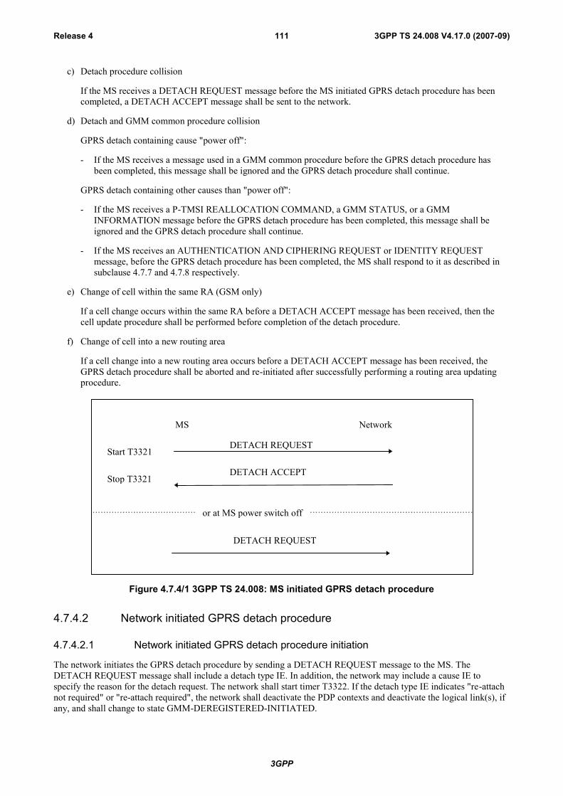
3GPP
3GPP TS 24.008 V4.17.0 (2007-09)Release 4 111
c) Detach procedure collision
If the MS receives a DETACH REQUEST message before the MS initiated GPRS detach procedure has beencompleted, a DETACH ACCEPT message shall be sent to the network.
d) Detach and GMM common procedure collision
GPRS detach containing cause "power off":
- If the MS receives a message used in a GMM common procedure before the GPRS detach procedure hasbeen completed, this message shall be ignored and the GPRS detach procedure shall continue.
GPRS detach containing other causes than "power off":
- If the MS receives a P-TMSI REALLOCATION COMMAND, a GMM STATUS, or a GMMINFORMATION message before the GPRS detach procedure has been completed, this message shall beignored and the GPRS detach procedure shall continue.
- If the MS receives an AUTHENTICATION AND CIPHERING REQUEST or IDENTITY REQUESTmessage, before the GPRS detach procedure has been completed, the MS shall respond to it as described insubclause 4.7.7 and 4.7.8 respectively.
e) Change of cell within the same RA (GSM only)
If a cell change occurs within the same RA before a DETACH ACCEPT message has been received, then thecell update procedure shall be performed before completion of the detach procedure.
f) Change of cell into a new routing area
If a cell change into a new routing area occurs before a DETACH ACCEPT message has been received, theGPRS detach procedure shall be aborted and re-initiated after successfully performing a routing area updatingprocedure.
MS Network
DETACH REQUESTStart T3321
DETACH ACCEPTStop T3321
or at MS power switch off
DETACH REQUEST
Figure 4.7.4/1 3GPP TS 24.008: MS initiated GPRS detach procedure
4.7.4.2 Network initiated GPRS detach procedure
4.7.4.2.1 Network initiated GPRS detach procedure initiation
The network initiates the GPRS detach procedure by sending a DETACH REQUEST message to the MS. TheDETACH REQUEST message shall include a detach type IE. In addition, the network may include a cause IE tospecify the reason for the detach request. The network shall start timer T3322. If the detach type IE indicates "re-attachnot required" or "re-attach required", the network shall deactivate the PDP contexts and deactivate the logical link(s), ifany, and shall change to state GMM-DEREGISTERED-INITIATED.
3GPP
3GPP TS 24.008 V4.17.0 (2007-09)Release 4 112
4.7.4.2.2 Network initiated GPRS detach procedure completion by the MS
When receiving the DETACH REQUEST message and the detach type IE indicates "re-attach required", the MS shalldeactivate the PDP contexts and deactivate the logical link(s), if any. The MS shall then send a DETACH ACCEPTmessage to the network and shall change state to GMM-DEREGISTERED. The MS shall, after the completion of theGPRS detach procedure, initiate a GPRS attach procedure. The MS should also activate PDP context(s) to replace anypreviously active PDP contexts.
NOTE: In some cases, user interaction may be required and then the MS cannot activate the PDP context(s)automatically.
A GPRS MS operating in MS operation mode A or B in network operation mode I, which receives an DETACHREQUEST message with detach type indicating "re-attach required" or "re-attach not required" and no cause code, isonly detached for GPRS services in the network.
When receiving the DETACH REQUEST message and the detach type IE indicates "IMSI detach", the MS shall notdeactivate the PDP contexts. The MS shall set the MM update status to U2 NOT UPDATED. A MS in operation modeA or B in network operation mode I may send a DETACH ACCEPT message to the network, and shall re-attach to non-GPRS service by performing the combined routing area updating procedure according to subclause 4.7.5.2, sending aROUTING AREA UPDATE REQUEST message with Update type IE indicating "combined RA/LA updating withIMSI attach". A MS in operation mode C, or in MS operation mode A or B in network operation mode II or III, shallsend a DETACH ACCEPT message to the network.
If the detach type IE indicates "IMSI detach", or "re-attach required" then the MS shall ignore the cause code ifreceived.
If the detach type information element value indicates "re-attach required" or "re-attach not required" and the MS isattached for GPRS and non-GPRS services and the network operates in network operation mode I, then if in the MS thetimer T3212 is not already running, the timer T3212 shall be set to its initial value and restarted.
When receiving the DETACH REQUEST message and the detach type IE indicates "re-attach not required" and thecause code is not "#2 (IMSI unknown in HLR)", the MS shall deactivate the PDP contexts and deactivate the logicallink(s), if any. The MS shall then send a DETACH ACCEPT message to the network and shall change state to GMM-DEREGISTERED.
If the detach type IE indicates "re-attach not required", then, depending on the received cause code, the MS shall act asfollows:
# 2 (IMSI unknown in HLR);
The MS shall set the update status to U3 ROAMING NOT ALLOWED and shall delete any TMSI, LAI andciphering key sequence number. The new MM state is MM IDLE. The SIM shall be considered as invalid fornon-GPRS services until switching off or the SIM is removed.
A GPRS MS operating in MS operation mode A or B in network operation mode I, is still IMSI attached forGPRS services in the network.
# 3 (Illegal MS);
# 6 (Illegal ME);
The MS shall set the GPRS update status to GU3 ROAMING NOT ALLOWED (and shall store it according tosubclause 4.1.3.2) and shall delete any P-TMSI, P-TMSI signature, RAI and GPRS ciphering key sequencenumber. The new GMM state is GMM-DEREGISTERED. The SIM shall be considered as invalid for GPRSservices until switching off or the SIM is removed.
A GPRS MS operating in MS operation mode A or B shall in addition set the update status to U3 ROAMINGNOT ALLOWED, shall delete any TMSI, LAI and ciphering key sequence number. The SIM shall beconsidered as invalid also for non-GPRS services until switching off or the SIM is removed.
3GPP
3GPP TS 24.008 V4.17.0 (2007-09)Release 4 113
# 7 (GPRS services not allowed);
The MS shall set the GPRS update status to GU3 ROAMING NOT ALLOWED (and shall store it according tosubclause 4.1.3.2) and shall delete any P-TMSI, P-TMSI signature, RAI and GPRS ciphering key sequencenumber. The SIM shall be considered as invalid for GPRS services until switching off or the SIM is removed.The new state is GMM-DEREGISTERED.
A GPRS MS operating in MS operation mode A or B in network operation mode I shall set the timer T3212 toits initial value and restart it, if it is not already running.
A GPRS MS operating in MS operation mode A or B in network operation mode I, is still IMSI attached for CSservices in the network.
# 8 (GPRS services and non-GPRS services not allowed);
The MS shall set the GPRS update status to GU3 ROAMING NOT ALLOWED (and shall store it according tosubclause 4.1.3.2) and shall delete any P-TMSI, P-TMSI signature, RAI and GPRS ciphering key sequencenumber. The new GMM state is GMM-DEREGISTERED.
The MS shall set the update status to U3 ROAMING NOT ALLOWED, shall delete any TMSI, LAI andciphering key sequence number. The SIM shall be considered as invalid for GPRS and non-GPRS services untilswitching off or the SIM is removed.
# 11 (PLMN not allowed);
The MS shall delete any RAI or LAI, P-TMSI, P-TMSI signature and GPRS ciphering key sequence number,shall set the GPRS update status to GU3 ROAMING NOT ALLOWED (and shall store it according tosubclause 4.1.3.2). The new GMM state is GMM-DEREGISTERED.
The MS shall store the PLMN identity in the "forbidden PLMN list".
If no RR connection exists, the MS shall perform the following additional actions immediately. If the MS isoperating in MS operation mode A and an RR connection exists, the MS shall perform these actions when theRR connection is subsequently released:
- A GPRS MS operating in MS operation mode A or B shall set the update status to U3 ROAMING NOTALLOWED and shall delete any TMSI, LAI and ciphering key sequence number. The new MM state is MMIDLE.
- The MS shall perform a PLMN selection according to 3GPP TS 23.122 [14].
# 12 (Location area not allowed);
The MS shall delete any RAI, P-TMSI, P-TMSI signature GPRS ciphering key sequence number, shall set theGPRS update status to GU3 ROAMING NOT ALLOWED(and shall store it according to clause 4.1.3.2) andshall reset the attach attempt counter. The state is changed to GMM-DEREGISTERED.LIMITED-SERVICE.
The MS shall store the LAI in the list of "forbidden location areas for regional provision of service".
If no RR connection exists, the MS shall perform the following additional actions immediately. If the MS isoperating in MS operation mode A and an RR connection exists, the MS shall perform these actions when theRR connection is subsequently released:
- If the MS is IMSI attached, the MS shall set the update status to U3 ROAMING NOT ALLOWED, shalldelete any TMSI, LAI and ciphering key sequence number and shall reset the location update attemptcounter. The new MM state is MM IDLE.
- The MS shall perform a cell selection according to 3GPP TS 43.022 and 3GPP TS 25.304.
# 13 (Roaming not allowed in this location area);
The MS shall delete any RAI, P-TMSI, P-TMSI signature and GPRS ciphering key sequence number, shall setthe GPRS update status to GU3 ROAMING NOT ALLOWED (and shall store it according to clause 4.1.3.2) andshall reset the attach attempt counter. The state is changed to GMM-DEREGISTERED.LIMITED-SERVICE oroptionally to GMM-DEREGISTERED.PLMN-SEARCH.
3GPP
3GPP TS 24.008 V4.17.0 (2007-09)Release 4 114
The MS shall store the LAI in the list of "forbidden location areas for roaming".
If no RR connection exists, the MS shall perform the following additional actions immediately. If the MS isoperating in MS operation mode A and an RR connection exists, the MS shall perform these actions when theRR connection is subsequently released:
- If the MS is IMSI attached, the MS shall set the update status to U3 ROAMING NOT ALLOWED, shalldelete any TMSI, LAI and ciphering key sequence number and shall reset the location update attemptcounter. The new MM state is MM IDLE.
- The MS shall perform a PLMN selection according to 3GPP TS 23.122 [14].
# 14 (GPRS services not allowed in this PLMN);
The MS shall delete any RAI, P-TMSI, P-TMSI signature, and GPRS ciphering key sequence number stored,shall set the GPRS update status to GU3 ROAMING NOT ALLOWED (and shall store it according tosubclause 4.1.3.2) and shall change to state GMM-DEREGISTERED.
The MS shall store the PLMN identity in the "forbidden PLMNs for GPRS service" list.
A GPRS MS operating in MS operation mode A or B in network operation mode I shall set the timer T3212 toits initial value and restart it, if it is not already running.
A GPRS MS operating in MS operation mode A or B, is still IMSI attached for CS services in the network.
# 15 (No Suitable Cells In Location Area);
The MS shall delete any RAI, P-TMSI, P-TMSI signature and GPRS ciphering key sequence number, shall setthe GPRS update status to GU3 ROAMING NOT ALLOWED(and shall store it according to clause 4.1.3.2) andshall reset the attach attempt counter. The state is changed to GMM-DEREGISTERED.LIMITED-SERVICE.
The MS shall store the LAI in the list of "forbidden location areas for roaming".
If no RR connection exists, the MS shall perform the following additional actions immediately. If the MS isoperating in MS operation mode A and an RR connection exists, the MS shall perform these actions when theRR connection is subsequently released:
- If the MS is IMSI attached, the MS shall set the update status to U3 ROAMING NOT ALLOWED, shalldelete any TMSI, LAI and ciphering key sequence number and shall reset the location update attemptcounter. The new MM state is MM IDLE.
- The MS shall search for a suitable cell in another location area in the same PLMN according to3GPP TS 43.022 and 3GPP TS 25.304.
Other cause values shall not impact the update status. Further actions of the MS are implementation dependent.
4.7.4.2.3 Network initiated GPRS detach procedure completion by the network
The network shall, upon receipt of the DETACH ACCEPT message, stop timer T3322 and shall change state to GMM-DEREGISTERED.
4.7.4.2.4 Abnormal cases on the network side
The following abnormal cases can be identified:
a) T3322 time-out
On the first expiry of the timer, the network shall retransmit the DETACH REQUEST message and shall starttimer T3322. This retransmission is repeated four times, i.e. on the fifth expiry of timer T3322, the GPRS detachprocedure shall be aborted and the network changes to state GMM-DEREGISTERED.
b) Low layer failure
The GPRS detach procedure is aborted and the network changes to state GMM-DEREGISTERED.
c) GPRS detach procedure collision

3GPP
3GPP TS 24.008 V4.17.0 (2007-09)Release 4 115
If the network receives a DETACH REQUEST message with "switching off" indicated, before the networkinitiated GPRS detach procedure has been completed, both procedures shall be considered completed.
If the network receives a DETACH REQUEST message without "switching off" indicated, before the networkinitiated GPRS detach procedure has been completed, the network shall send a DETACH ACCEPT message tothe MS.
d) GPRS detach and GPRS attach procedure collision
If the network receives an ATTACH REQUEST message before the network initiated GPRS detach procedurewith type of detach 're-attach not required' has been completed, the network shall ignore the ATTACHREQUEST message. If the detach type IE value, sent in the DETACH REQUEST message, indicates "re-attachrequired" the detach procedure is aborted and the GPRS attach procedure shall be progressed after the PDPcontexts have been deleted. If the detach type IE value, sent in the DETACH REQUEST message, indicates"IMSI detach" the detach procedure is aborted and the GPRS attach procedure shall be progressed.
e) GPRS detach and routing area updating procedure collision
GPRS detach containing detach type "re-attach required" or "re-attach not required":
If the network receives a ROUTING AREA UPDATE REQUEST message before the network initiatedGPRS detach procedure has been completed, the detach procedure shall be progressed, i.e. the ROUTINGAREA UPDATE REQUEST message shall be ignored.
GPRS detach containing detach type "IMSI detach":
If the network receives a ROUTING AREA UPDATE REQUEST message before the network initiatedGPRS detach procedure has been completed, the network shall abort the detach procedure, shall stop T3322and shall progress the routing area update procedure.
f) GPRS detach and service request procedure collision
If the network receives a SERVICE REQUEST message before the network initiated GPRS detach procedurehas been completed, the network shall ignore the SERVICE REQUEST message.
MS Network
DETACH REQUESTStart T3322
DETACH ACCEPTStop T3322
Figure 4.7.4/2 3GPP TS 24.008: Network initiated GPRS detach procedure
4.7.5 Routing area updating procedureThis procedure is used for:
- normal routing area updating to update the registration of the actual routing area of an MS in the network. Thisprocedure is used by GPRS MSs in MS operation mode C and by GPRS MSs in MS operation modes A or B thatare IMSI attached for GPRS and non-GPRS services if the network operates in network operation mode II or III;
- combined routing area updating to update the registration of the actual routing and location area of an MS in thenetwork. This procedure is used by GPRS MSs in MS operation modes A or B that are IMSI attached for GPRSand non-GPRS services provided that the network operates in network operation mode I;
- periodic routing area updating. This procedure is used by GPRS MSs in MS operation mode C and by GPRSMSs in MS operation modes A or B that are IMSI attached for GPRS or for GPRS and non-GPRS servicesindependent of the network operation mode;

3GPP
3GPP TS 24.008 V4.17.0 (2007-09)Release 4 116
- IMSI attach for non-GPRS services when the MS is IMSI attached for GPRS services. This procedure is used byGPRS MSs in MS operation modes A or B, if the network operates in network operation mode I;
- in GSM, resuming GPRS services when the RR sublayer indicated a resumption failure after dedicated modewas left, see 3GPP TS 44.018 [84];
- in GSM, updating the network with the new MS Radio Access Capability IE when the content of the IE haschanged. Normal or combined routing area updating procedure is used;
- updating the network with the new DRX parameter IE when the content of the IE has changed;
NOTE 1: Such changes can be used e.g. when the MS activates a PDP context with service requirements thatcannot be met with the current DRX parameter. As PDP context(s) are activated and deactivated, theGMM context will be updated with an appropriate DRX parameter;
- UMTS to GSM and for GSM to UMTS intersystem change, see subclause 4.7.1.7; or
- in UMTS, to re-synchronize the PMM mode of MS and network after RRC connection release with cause"Directed signalling connection re-establishment", see subclause 4.7.2.5.
The routing area updating procedure shall also be used by a MS which is attached for GPRS services if a new PLMN isentered (see 3GPP TS 23.122 [14]).
Subclause 4.7.5.1 describes the routing area updating procedures for updating the routing area only. The combinedrouting area updating procedure used to update both the routing and location area is described in subclause 4.7.5.2.
The routing area updating procedure is always initiated by the MS. It is only invoked in state GMM-REGISTERED.
To limit the number of subsequently rejected routing area update attempts, a routing area updating attempt counter isintroduced. The routing area updating attempt counter shall be incremented as specified in subclause 4.7.5.1.5.Depending on the value of the routing area updating attempt counter, specific actions shall be performed. The routingarea updating attempt counter shall be reset when:
- a GPRS attach procedure is successfully completed; or
- a routing area updating procedure is successfully completed;
and additionally when the MS is in substate ATTEMPTING-TO-UPDATE:
- a new routing area is entered;
- expiry of timer T3302; or
- at request from registration function.
The mobile equipment shall contain a list of "forbidden location areas for roaming", as well as a list of "forbiddenlocation areas for regional provision of service". The handling of these lists is described in subclause 4.4.1.
The Mobile Equipment shall contain a list of "equivalent PLMNs". The handling of this list is described insubclause 4.4.1.
In, GSM, user data transmission in the MS shall be suspended during the routing area updating procedure; user datareception shall be possible. User data transmission in the network shall be suspended during the routing area updatingprocedure, if a new P-TMSI is assigned.
In UMTS, user data transmission and reception in the MS shall not be suspended during the routing area updatingprocedure. User data transmission in the network shall not be suspended during the routing area updating procedure.
In UMTS, when a ROUTING AREA UPDATE REQUEST is received by the SGSN over a new PS signallingconnection while there is an ongoing PS signalling connection (network is already in mode PMM-CONNECTED) forthis UE, the network shall progress the routing area update procedure as normal and release the previous PS signallingconnection when the routing area update procedure has been accepted by the network.
NOTE 2: The re-establishment of the radio bearers of active PDP contexts is done as described in subclause"Service Request procedure".
3GPP
3GPP TS 24.008 V4.17.0 (2007-09)Release 4 117
The network informs the MS about the support of specific features, such as LCS-MOLR, in the “Network featuresupport” Information Element. The information is either explicitly given by sending the “Network feature support” IEor implicitly by not sending it. The handling in the network is described in subclause 9.4.15.11. The MS may use theindication to inform the user about the availability of the appropriate services and it shall not request services that havenot been indicated as available.
4.7.5.1 Normal and periodic routing area updating procedure
Periodic routing area updating is used to periodically notify the availability of the MS to the network. The value of theupdate type IE in the ROUTING AREA UPDATE REQUEST message shall indicate "periodic updating". Theprocedure is controlled in the MS by timer T3312. When timer T3312 expires, the periodic routing area updatingprocedure is started. Start and reset of timer T3312 is described in subclause 4.7.2.2.
In GSM, the normal routing area updating procedure is initiated:
- when the MS detects a change of the routing area in state GMM-REGISTERED;
- when the MS determines that GPRS resumption shall be performed;
- when the MS needs to update the network with the new MS Radio Access Capability IE; or
- when the MS needs to update the network with the new DRX parameter IE.
The ROUTING AREA UPDATE REQUEST message shall always be the first data sent by the MS when a routing areaborder is crossed. The routing area identification is broadcast on the broadcast channel(s).
In UMTS, the normal routing area updating procedure is initiated when the MS detects a change of the routing area instate GMM-REGISTERED. The ROUTING AREA UPDATE REQUEST message shall always be the first GMMmessage sent by the MS when a routing area border is crossed.
A normal routing area updating shall abort any ongoing GMM procedure. Aborted GMM procedures may be repeatedafter the normal routing area updating procedure has been successfully performed. The value of the update type IEincluded in the message shall indicate "normal routing area updating".
4.7.5.1.1 Normal and periodic routing area updating procedure initiation
To initiate the normal routing area updating procedure, the MS sends the message ROUTING AREA UPDATEREQUEST to the network, starts timer T3330 and changes to state GMM-ROUTING-AREA-UPDATING-INITIATED. The message ROUTING AREA UPDATE REQUEST shall contain the P-TMSI signature when receivedwithin a previous ATTACH ACCEPT or ROUTING AREA UPDATE ACCEPT message.
In UMTS, if the MS wishes to prolong the established PS signalling connection after the normal routing area updatingprocedure, it may set a follow-on request pending indicator on.
4.7.5.1.2 GMM Common procedure initiation
The network may initiate GMM common procedures, e.g. the GMM authentication and ciphering procedure.
4.7.5.1.3 Normal and periodic routing area updating procedure accepted by the network
If the routing area updating request has been accepted by the network, a ROUTING AREA UPDATE ACCEPTmessage shall be sent to the MS. The network may assign a new P-TMSI and/or a new P-TMSI signature for the MS. Ifa new P-TMSI and/or P-TMSI signature have been assigned to the MS, it/they shall be included in the ROUTINGAREA UPDATE ACCEPT message together with the routing area identification.
If a new DRX parameter was included in the ROUTING AREA UPDATE REQUEST message, the network shall storethe new DRX parameter and use it for the downlink transfer of signalling and user data.
In GSM the Cell Notification information element shall be included in the ROUTING AREA UPDATE ACCEPTmessage in order to indicate the ability of the network to support the Cell Notification.
The network shall change to state GMM-COMMON-PROCEDURE-INITIATED and shall start the supervision timerT3350 as described in subclause 4.7.6.
3GPP
3GPP TS 24.008 V4.17.0 (2007-09)Release 4 118
If the LAI or PLMN identity contained in the ROUTING AREA UPDATE ACCEPT message is a member of any ofthe "forbidden" lists then any such entry shall be deleted.
In UMTS, the network should prolong the PS signalling connection if the mobile station has indicated a follow-onrequest pending in ROUTING AREA UPDATE REQUEST. The network may also prolong the PS signallingconnection without any indication from the mobile terminal.
If the PDP context status information element is included in ROUTING AREA UPDATE REQUEST message, then thenetwork shall deactivate all those PDP contexts locally (without peer to peer signalling between the MS and thenetwork), which are not in SM state PDP-INACTIVE on network side but are indicated by the MS as being in statePDP-INACTIVE.
Upon receipt of a ROUTING AREA UPDATE ACCEPT message, the MS stores the received routing areaidentification, stops timer T3330, shall reset the routing area updating attempt counter and sets the GPRS update statusto GU1 UPDATED. If the message contains a P-TMSI, the MS shall use this P-TMSI as new temporary identity forGPRS services and shall store the new P-TMSI. If no P-TMSI was included by the network in the ROUTING AREAUPDATING ACCEPT message, the old P-TMSI shall be kept. Furthermore, the MS shall store the P-TMSI signature ifreceived in the ROUTING AREA UPDATING ACCEPT message. If no P-TMSI signature was included in themessage, the old P-TMSI signature, if available, shall be deleted.
If the ROUTING AREA UPDATE REQUEST message was used to update the network with a new DRX parameter IE,the MS shall start using the new DRX parameter upon receipt of the ROUTING AREA UPDATE ACCEPT message.
If the PDP context status information element is included in ROUTING AREA UPDATE ACCEPT message, then theMS shall deactivate all those PDP contexts locally (without peer to peer signalling between the MS and network), whichare not in SM state PDP-INACTIVE in the MS but are indicated by the network as being in state PDP-INACTIVE.
In GSM, if the ROUTING AREA UPDATE ACCEPT message contains the Cell Notification information element, thenthe MS shall start to use the LLC NULL frame to perform cell updates.
The network may also send a list of "equivalent PLMNs" in the ROUTING AREA UPDATE ACCEPT message. Eachentry of the list contains a PLMN code (MCC+MNC). The mobile station shall store the list, as provided by thenetwork, except that any PLMN code that is already in the "forbidden PLMN" list shall be removed from the"equivalent PLMNs" list before it is stored by the mobile station. In addition the mobile station shall add to the storedlist the PLMN code of the network that sent the list. All PLMNs in the stored list shall be regarded as equivalent to eachother for PLMN selection, cell selection/re-selection and handover. The stored list in the mobile station shall bereplaced on each occurrence of the ROUTING AREA UPDATE ACCEPT message. If no list is contained in themessage, then the stored list in the mobile station shall be deleted. The list shall be stored in the mobile station whileswitched off so that it can be used for PLMN selection after switch on.
A ROUTING AREA UPDATE COMPLETE message shall be returned to the network if the ROUTING AREAUPDATE ACCEPT message contained:
- a P-TMSI; and/or
- Receive N-PDU Numbers (see 3GPP TS 44.065 [78] and 3GPP TS 25.322).
In the latter case the Receive N-PDU Numbers values valid in the MS, shall be included in the ROUTING AREAUPDATE COMPLETE message.
NOTE: In UMTS, after a routing area updating procedure, the mobile station can initiate Service Requestprocedure to request the resource reservation for the active PDP contexts if the resources have beenreleased by the network or send upper layer message (e.g. ACTIVATE PDP CONTEXT REQUEST) tothe network via the existing PS signaling connection.
After that in UMTS, if the mobile station has indicated follow-on request pending and has a CM application requestpending, it shall send an appropriate message (for example ACTIVATE PDP CONTEXT REQUEST) to the network.
3GPP
3GPP TS 24.008 V4.17.0 (2007-09)Release 4 119
4.7.5.1.4 Normal and periodic routing area updating procedure not accepted by thenetwork
If the routing area updating cannot be accepted, the network sends a ROUTING AREA UPDATE REJECT message tothe MS. An MS that receives a ROUTING AREA UPDATE REJECT message, stops timer T3330, and for all causesexcept #12, #14 and #15 deletes the list of "equivalent PLMNs".
The MS shall then take different actions depending on the received reject cause value:
# 3 (Illegal MS);
# 6 (Illegal ME);
The MS shall set the GPRS update status to GU3 ROAMING NOT ALLOWED (and shall store it according tosubclause 4.1.3.2) and enter the state GMM-DEREGISTERED. Furthermore, it shall delete any P-TMSI, P-TMSI signature, RAI and GPRS ciphering key sequence number and shall consider the SIM as invalid for GPRSservices until switching off or the SIM is removed.
If the MS is IMSI attached, the MS shall set the update status to U3 ROAMING NOT ALLOWED, shall deleteany TMSI, LAI and ciphering key sequence number. The SIM shall be considered as invalid also for non-GPRSservices until switching off or the SIM is removed.
# 7 (GPRS services not allowed);
The MS shall set the GPRS update status to GU3 ROAMING NOT ALLOWED (and shall store it according tosubclause 4.1.3.2.9) and shall delete any P-TMSI, P-TMSI signature, RAI and GPRS ciphering key sequencenumber. The SIM shall be considered as invalid for GPRS services until switching off or the SIM is removed.The new state is GMM-DEREGISTERED.
If the update type is "periodic updating" a GPRS MS operating in MS operation mode A or B innetworkoperation mode I shall set the timer T3212 to its initial value and restart it, if it is not already running.
# 9 (MS identity cannot be derived by the network);
The MS shall set the GPRS update status to GU2 NOT UPDATED (and shall store it according tosubclause 4.1.3.2), enter the state GMM-DEREGISTERED, and shall delete any P-TMSI, P-TMSI signature,RAI and GPRS ciphering key sequence number. Subsequently, the MS may automatically initiate the GPRSattach procedure.
# 10 (Implicitly detached);
The MS shall change to state GMM-DEREGISTERED.NORMAL-SERVICE. The MS shall then perform a newattach procedure. The MS should also activate PDP context(s) to replace any previously active PDP contexts.
NOTE: In some cases, user interaction may be required and then the MS cannot activate the PDP context(s)automatically.
# 11 (PLMN not allowed);
- The MS shall delete any RAI, P-TMSI, P-TMSI signature and GPRS ciphering key sequence number, shall setthe GPRS update status to GU3 ROAMING NOT ALLOWED (and shall store it according to subclause 4.1.3.2)and enter the state GMM-DEREGISTERED.
The MS shall store the PLMN identity in the "forbidden PLMN list".
If no RR connection exists, the MS shall perform the following additional actions immediately. If the MS isoperating in MS operation mode A and an RR connection exists, the MS shall perform these actions when theRR connection is subsequently released:
- If the MS is IMSI attached, the MS shall set the update status to U3 ROAMING NOT ALLOWED and shalldelete any TMSI, LAI and ciphering key sequence number and shall reset the location update attemptcounter. The new MM state is MM IDLE.
- The MS shall perform a PLMN selection according to 3GPP TS 23.122 [14].
# 12 (Location area not allowed);

3GPP
3GPP TS 24.008 V4.17.0 (2007-09)Release 4 120
The MS shall delete any RAI, P-TMSI, P-TMSI signature and GPRS ciphering key sequence number, shall setthe GPRS update status to GU3 ROAMING NOT ALLOWED (and shall store it according to clause 4.1.3.2),shall reset the routing area updating attempt counter and shall change to state GMM-DEREGISTERED.LIMITED-SERVICE.
The mobile station shall store the LAI in the list of "forbidden location areas for regional provision of service".
If no RR connection exists, the MS shall perform the following additional actions immediately. If the MS isoperating in MS operation mode A and an RR connection exists, the MS shall perform these actions when theRR connection is subsequently released:
- If the MS is IMSI attached, the MS shall set the update status to U3 ROAMING NOT ALLOWED, shalldelete any TMSI, LAI and ciphering key sequence number and shall reset the location update attemptcounter. The new MM state is MM IDLE.
- The MS shall perform a cell selection according to 3GPP TS 43.022 and 3GPP TS 25.304.
# 13 (Roaming not allowed in this location area);
The MS shall set the GPRS update status to GU3 ROAMING NOT ALLOWED (and shall store it according toclause 4.1.3.2) shall reset the routing area updating attempt counter and shall change to state GMM-REGISTERED.LIMITED-SERVICE.
The MS shall store the LAI in the list of "forbidden location areas for roaming".
If no RR connection exists, the MS shall perform the following additional actions immediately. If the MS isoperating in MS operation mode A and an RR connection exists, the MS shall perform these actions when theRR connection is subsequently released:
- If the MS is IMSI attached, the MS shall set the update status to U3 ROAMING NOT ALLOWED and shallreset the location update attempt counter. The new MM state is MM IDLE.
- The MS shall perform a PLMN selection according to 3GPP TS 23.122 [14].
# 14 (GPRS services not allowed in this PLMN);
The MS shall delete any RAI, P-TMSI, P-TMSI signature, and GPRS ciphering key sequence number stored,shall set the GPRS update status to GU3 ROAMING NOT ALLOWED (and shall store it according tosubclause 4.1.3.2) and shall change to state GMM-DEREGISTERED.
The MS shall store the PLMN identity in the "forbidden PLMNs for GPRS service" list. A GPRS MS operatingin MS operation mode C shall perform a PLMN selection instead of a cell selection.
If the update type is "periodic updating" a GPRS MS operating in MS operation mode A or B in networkoperation mode I shall set the timer T3212 to its initial value and restart it, if it is not already running.
A GPRS MS operating in MS operation mode A or B in network operation mode II or III, is still IMSI attachedfor CS services in the network.
# 15 (No Suitable Cells In Location Area);
The MS shall set the GPRS update status to GU3 ROAMING NOT ALLOWED (and shall store it according toclause 4.1.3.2) shall reset the routing area updating attempt counter and shall change to state GMM-REGISTERED.LIMITED-SERVICE.
The MS shall store the LAI in the list of "forbidden location areas for roaming".
If no RR connection exists, the MS shall perform the following additional actions immediately. If the MS isoperating in MS operation mode A and an RR connection exists, the MS shall perform these actions when theRR connection is subsequently released:
- If the MS is IMSI attached, the MS shall set the update status to U3 ROAMING NOT ALLOWED and shallreset the location update attempt counter. The new MM state is MM IDLE.
- The MS shall search for a suitable cell in another location area in the same PLMN according to3GPP TS 43.022 and 3GPP TS 25.304.

3GPP
3GPP TS 24.008 V4.17.0 (2007-09)Release 4 121
Other values are considered as abnormal cases. The specification of the MS behaviour in those cases is described insubclause 4.7.5.1.5.
4.7.5.1.5 Abnormal cases in the MS
The following abnormal cases can be identified:
a) Access barred because of access class control
The routing area updating procedure shall not be started. The MS stays in the current serving cell and applies thenormal cell reselection process. The procedure is started as soon as possible and if still necessary, i.e. when thebarred state is removed or because of a cell change.
b) Lower layer failure before the ROUTING AREA UPDATE ACCEPT or ROUTING AREA UPDATE REJECTmessage is received
The procedure shall be aborted. The MS shall proceed as described below.
c) T3330 time-out
The procedure is restarted four times, i.e. on the fifth expiry of timer T3330, the MS shall abort the procedure.The MS shall proceed as described below.
d) ROUTING AREA UPDATE REJECT, other causes than those treated in subclause 4.7.5.1.4
The MS shall proceed as described below.
e) If a routing area border is crossed, when the MS is in state GMM-ROUTING-AREA-UPDATE-INITIATED, therouting area updating procedure shall be aborted and re-initiated immediately. The MS shall set the GPRS updatestatus to GU2 NOT UPDATED.
f) In GSM, if a cell change occurs within the same RA, when the MS is in state GMM-ROUTING-AREA-UPDATE-INITIATED, the cell update procedure is performed, before completion of the routing area updatingprocedure.
g) Routing area updating and detach procedure collision
GPRS detach containing detach type"re-attach required" or "re-attach not required":
If the MS receives a DETACH REQUEST message before the routing area updating procedure has beencompleted, the routing area updating procedure shall be aborted and the GPRS detach procedure shall beprogressed.
GPRS detach containing detach type "IMSI detach":
If the MS receives a DETACH REQUEST message before the routing area updating procedure has beencompleted, the routing area updating procedure shall be progressed, i.e. the DETACH REQUEST messageshall be ignored.
h) Routing area updating and P-TMSI reallocation procedure collision
If the MS receives a P-TMSI REALLOCATION REQUEST message before the routing area updating procedurehas been completed, the P-TMSI reallocation procedure shall be aborted and the routing area updating procedureshall be progressed.
In cases b, c and d the MS shall proceed as follows:
Timer T3330 shall be stopped if still running. The routing area updating attempt counter shall be incremented.
If the routing area updating attempt counter is less than 5, and the stored RAI is equal to the RAI of the currentserving cell and the GMM update status is equal to GU1 UPDATED:
- the MS shall keep the GMM update status to GU1 UPDATED and changes state to GMM-REGISTERED.NORMAL-SERVICE. The MS shall start timer T3311. When timer T3311 expires therouting area updating procedure is triggered again.
3GPP
3GPP TS 24.008 V4.17.0 (2007-09)Release 4 122
If the routing area updating attempt counter is less than 5, and the stored RAI is different to the RAI of thecurrent serving cell or the GMM update status is different to GU1 UPDATED:
- the MS shall start timer T3311, shall set the GPRS update status to GU2 NOT UPDATED and changes stateto GMM-REGISTERED.ATTEMPTING-TO-UPDATE.
If the routing area updating attempt counter is greater than or equal to 5:
- the MS shall start timer T3302, shall set the GPRS update status to GU2 NOT UPDATED and shall changeto state GMM-REGISTERED.ATTEMPTING-TO-UPDATE or optionally to GMM-REGISTERED.PLMN-SEARCH (see subclause 4.2.5.1.8).
In UMTS, in case c the MS shall release the PS signaling connection and in case d the network shall release thePS signaling connection for this MS (see 3GPP TS 25.331 [23c]).
4.7.5.1.6 Abnormal cases on the network side
The following abnormal cases can be identified:
a) If a lower layer failure occurs before the message ROUTING AREA UPDATE COMPLETE has been receivedfrom the MS and a P-TMSI and/or PTMSI signature has been assigned, the network shall abort the procedureand shall consider both, the old and new P-TMSI and the corresponding P-TMSI signatures as valid until the oldP-TMSI can be considered as invalid by the network (see subclause 4.7.1.5). During this period the network mayuse the identification procedure followed by a P-TMSI reallocation procedure if the old P-TMSI is used by theMS in a subsequent message.
NOTE: Optionally, paging with IMSI may be used if paging with old and new P-TMSI fails. Paging with IMSIcauses the MS to re-attach as described in subclause 4.7.9.1.
b) Protocol error
If the ROUTING AREA UPDATE REQUEST message has been received with a protocol error, the networkshall return a ROUTING AREA UPDATE REJECT message with one of the following reject causes:
#96: Mandatory information element error;
#99: Information element non-existent or not implemented;
#100: Conditional IE error;
#111: Protocol error, unspecified.
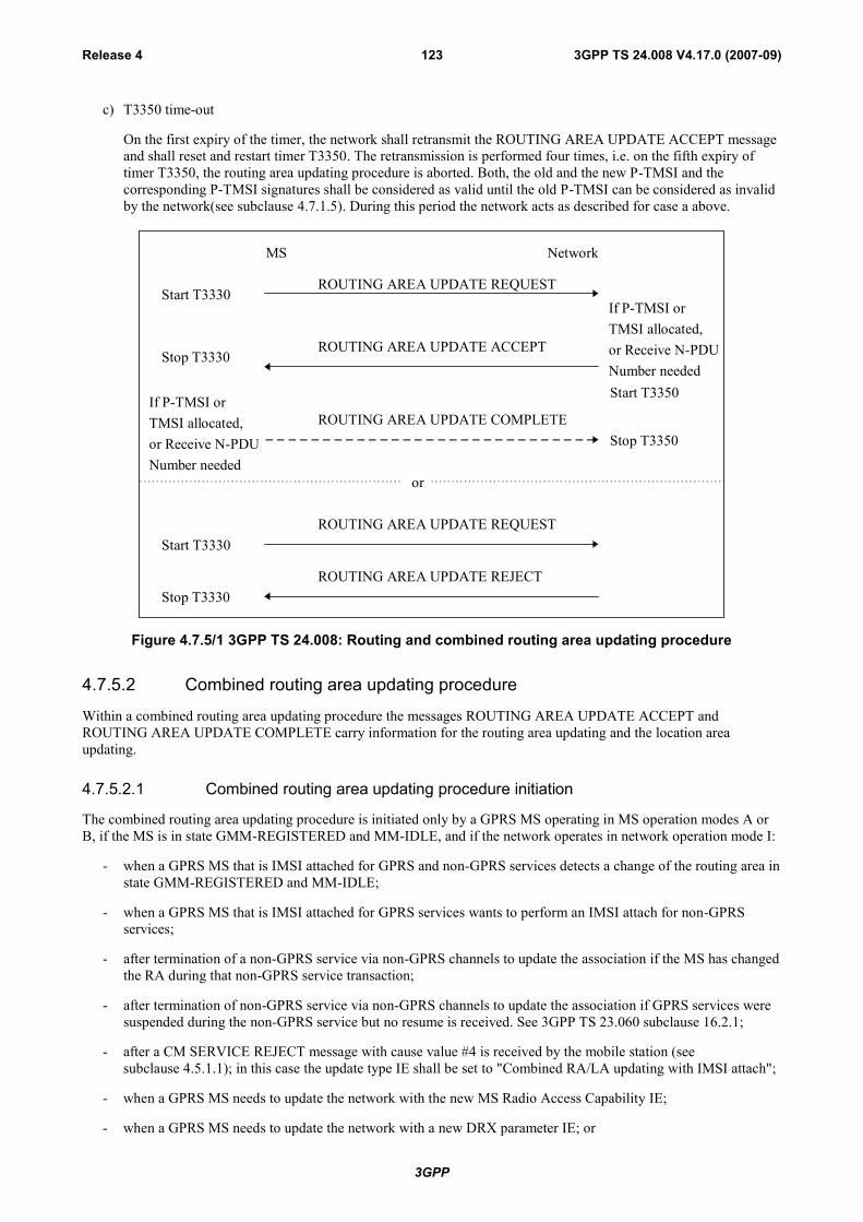
3GPP
3GPP TS 24.008 V4.17.0 (2007-09)Release 4 123
c) T3350 time-out
On the first expiry of the timer, the network shall retransmit the ROUTING AREA UPDATE ACCEPT messageand shall reset and restart timer T3350. The retransmission is performed four times, i.e. on the fifth expiry oftimer T3350, the routing area updating procedure is aborted. Both, the old and the new P-TMSI and thecorresponding P-TMSI signatures shall be considered as valid until the old P-TMSI can be considered as invalidby the network(see subclause 4.7.1.5). During this period the network acts as described for case a above.
MS Network
ROUTING AREA UPDATE REQUEST
If P-TMSI orTMSI allocated,or Receive N-PDUNumber needed
ROUTING AREA UPDATE ACCEPT
ROUTING AREA UPDATE COMPLETE
Stop T3330
Start T3330
Stop T3350
Start T3350
or
ROUTING AREA UPDATE REJECTStop T3330
ROUTING AREA UPDATE REQUESTStart T3330
If P-TMSI orTMSI allocated,or Receive N-PDUNumber needed
Figure 4.7.5/1 3GPP TS 24.008: Routing and combined routing area updating procedure
4.7.5.2 Combined routing area updating procedure
Within a combined routing area updating procedure the messages ROUTING AREA UPDATE ACCEPT andROUTING AREA UPDATE COMPLETE carry information for the routing area updating and the location areaupdating.
4.7.5.2.1 Combined routing area updating procedure initiation
The combined routing area updating procedure is initiated only by a GPRS MS operating in MS operation modes A orB, if the MS is in state GMM-REGISTERED and MM-IDLE, and if the network operates in network operation mode I:
- when a GPRS MS that is IMSI attached for GPRS and non-GPRS services detects a change of the routing area instate GMM-REGISTERED and MM-IDLE;
- when a GPRS MS that is IMSI attached for GPRS services wants to perform an IMSI attach for non-GPRSservices;
- after termination of a non-GPRS service via non-GPRS channels to update the association if the MS has changedthe RA during that non-GPRS service transaction;
- after termination of non-GPRS service via non-GPRS channels to update the association if GPRS services weresuspended during the non-GPRS service but no resume is received. See 3GPP TS 23.060 subclause 16.2.1;
- after a CM SERVICE REJECT message with cause value #4 is received by the mobile station (seesubclause 4.5.1.1); in this case the update type IE shall be set to "Combined RA/LA updating with IMSI attach";
- when a GPRS MS needs to update the network with the new MS Radio Access Capability IE;
- when a GPRS MS needs to update the network with a new DRX parameter IE; or
3GPP
3GPP TS 24.008 V4.17.0 (2007-09)Release 4 124
- in UMTS, to re-synchronize the PMM mode of MS and network after RRC connection release with cause"Directed signalling connection re-establishment", see subclause 4.7.2.5.
In GSM, the routing and location area identification are broadcast on the broadcast channel(s). A combined routing areaupdating procedure shall abort any ongoing GMM procedure. Aborted GMM procedures shall be repeated after thecombined routing area updating procedure has been successfully performed. The ROUTING AREA UPDATEREQUEST message shall always be the first message sent from the MS in the new routing area after routing areachange.
In UMTS, the routing and location area identification are broadcast on the broadcast channel(s) or sent to the MS viathe PS signaling connection. A combined routing area updating procedure shall abort any ongoing GMM procedure.Aborted GMM procedures may be repeated after the combined routing area updating procedure has been successfullyperformed. The ROUTING AREA UPDATE REQUEST message shall always be the first GMM message sent from theMS in the new routing area after routing area change.
To initiate a combined routing area updating procedure the MS sends the message ROUTING AREA UPDATEREQUEST to the network, starts timer T3330 and changes to state GMM-ROUTING-UPDATING-INITIATED andMM LOCATION UPDATING PENDING. The value of the update type IE in the message shall indicate "combinedRA/LA updating". If for the last attempt to update the registration of the location area a MM specific procedure wasperformed, the value of the update type IE in the ROUTING AREA UPDATE REQUEST message shall indicate"combined RA/LA updating with IMSI attach". Furthermore the MS shall include the TMSI status IE if no valid TMSIis available.
A GPRS MS in MS operation modes A or B that is in an ongoing circuit-switched transaction, shall initiate thecombined routing area updating procedure after the circuit-switched transaction has been released, if the MS haschanged the RA during the circuit-switched transaction and if the network operates in network operation mode I.
A GPRS MS in MS operation mode A shall initiate the combined routing area updating procedure with IMSI attachafter the circuit-switched transaction has been released if a GPRS attach was performed during the circuit-switchedtransaction and provided that the network operates in network operation mode I.
A GPRS MS in MS operation mode A shall perform the normal routing area update procedure during an ongoingcircuit-switched transaction.
In UMTS, if the MS wishes to prolong the established PS signalling connection after the normal routing area updatingprocedure when it is served under UMTS area, it may set a follow-on request pending indicator on.
In UMTS, when a ROUTING AREA UPDATE REQUEST is received by the SGSN over a new PS signallingconnection while there is an ongoing PS signalling connection (network is already in mode PMM-CONNECTED) forthis UE, the network shall progress the routing area update procedure as normal and release the previous PS signallingconnection when the routing area update procedure has been accepted by the network.
NOTE: The re-establishment of the radio bearers of active PDP contexts is done as described in subclause"Service Request procedure".
4.7.5.2.2 GMM Common procedure initiation
The network may initiate GMM common procedures, e.g. the GMM authentication and ciphering procedure.
4.7.5.2.3 Combined routing area updating procedure accepted by the network
Depending on the value of the update result IE received in the ROUTING AREA UPDATE ACCEPT message, twodifferent cases can be distinguished:
Case 1) The update result IE value indicates "combined RA/LA": Routing and location area updating issuccessful;
Case 2) The update result IE value indicates "RA only": Routing area updating is successful, but location areaupdating is not successful.
A ROUTING AREA UPDATE COMPLETE message shall be returned to the network if the ROUTING AREAUPDATE ACCEPT message contains:
- a P-TMSI and/or a TMSI; and/or

3GPP
3GPP TS 24.008 V4.17.0 (2007-09)Release 4 125
- Receive N-PDU Numbers (see 3GPP TS 44.065 [78] and 3GPP TS 25.322).
In the latter case, the Receive N-PDU Numbers that are valid in the MS shall be included in the ROUTING AREAUPDATE COMPLETE message.
In UMTS, the network should prolong the PS signalling connection if the mobile station has indicated a follow-onrequest pending in ROUTING AREA UPDATE REQUEST. The network may also prolong the PS signallingconnection without any indication from the mobile terminal.
4.7.5.2.3.1 Combined routing area updating successful
The description for normal routing area update as specified in subclause 4.7.5.1.3 shall be followed. In addition, thefollowing description for location area updating applies.
The handling at the receipt of the ROUTING AREA UPDATE ACCEPT depends on the value received in the updateresult IE as specified below.
The TMSI reallocation may be part of the combined routing area updating procedure. The TMSI allocated is thenincluded in the ROUTING AREA UPDATE ACCEPT message together with the location area identification (LAI).The network shall, in this case, change to state GMM-COMMON-PROCEDURE-INITIATED and shall start the timerT3350 as described in subclause 4.7.6.
The MS, receiving a ROUTING AREA UPDATE ACCEPT message, stores the received location area identification,stops timer T3330, enters state MM IDLE, reset the location update attempt counter and sets the update status to U1UPDATED. If the ROUTING AREA UPDATE ACCEPT message contains an IMSI, the mobile station is not allocatedany TMSI, and shall delete any TMSI accordingly. If the ROUTING AREA UPDATE ACCEPT message contains aTMSI, the MS shall use this TMSI as new temporary identity. The MS shall delete its old TMSI and shall store the newTMSI. In this case, an ROUTING AREA UPDATE COMPLETE message is returned to the network. If neither a TMSInor an IMSI has been included by the network in the ROUTING AREA UPDATE ACCEPT message, the old TMSI, ifany is available, shall be kept.
Any timer used for triggering the location updating procedure (e.g. T3211, T3212) shall be stopped if running.
The network receiving a ROUTING AREA UPDATE COMPLETE message stops timer T3350, changes to GMM-REGISTERED state and considers the new TMSI as valid.
4.7.5.2.3.2 Combined routing are updating successful for GPRS services only
The description for normal routing area update as specified in subclause 4.7.5.1.3 shall be followed. In addition, thefollowing description for location area updating applies.
The MS receiving the ROUTING AREA UPDATE ACCEPT message takes one of the following actions depending onthe reject cause:
#2 (IMSI unknown in HLR);
The MS shall set the update status to U3 ROAMING NOT ALLOWED and shall delete any TMSI, LAI and cipheringkey sequence number. The new MM state is MM IDLE. The SIM shall be considered as invalid for non-GPRS servicesuntil switching off or the SIM is removed.
#16 (MSC temporarily not reachable);
#17 (Network failure); or
#22 (Congestion).
The MS shall change to state GMM-REGISTERED.ATTEMPTING-TO-UPDATE-MM. Timer T3330 shall bestopped if still running. The routing area updating attempt counter shall be incremented. If the routing areaupdating attempt counter is less than 5, and the stored RAI is equal to the RAI of the current serving cell and theGMM update status is equal to GU1 UPDATED:
- the MS shall keep the GMM update status GU1 UPDATED and changes state to GMM-REGISTERED.ATTEMPTING-TO-UPDATE-MM. The MS shall start timer T3311. When timer T3311expires the combined routing area update procedure indicating "combined RA/LA updating with IMSIattach" is triggered again.
3GPP
3GPP TS 24.008 V4.17.0 (2007-09)Release 4 126
If the routing area updating attempt counter is greater than or equal to 5:
- the MS shall start timer T3302 and shall change to state GMM-REGISTERED.ATTEMPTING-TO-UPDATE-MM;
- a GPRS MS operating in MS operation mode A shall then proceed with appropriate MM specific procedure;a GPRS MS operating in MS operation mode B may then proceed with appropriate MM specific procedures.The MM sublayer shall act as in network operation mode II as long as the combined GMM procedures arenot successful and no new RA is entered. The new MM state is IDLE.
Other values are considered as abnormal cases. The combined routing area updating shall be considered as failed forGPRS and non-GPRS services. The specification of the MS behaviour in those cases is specified in subclause4.7.5.2.5.
4.7.5.2.4 Combined routing area updating not accepted by the network
If the combined routing area updating cannot be accepted, the network sends a ROUTING AREA UPDATE REJECTmessage to the MS. An MS that receives a ROUTING AREA UPDATE REJECT message stops timer T3330, entersstate MM IDLE, and for all causes except #12, #14 and #15 deletes the list of "equivalent PLMNs".
The MS shall then take different actions depending on the received reject cause:
# 3 (Illegal MS);
# 6 (Illegal ME), or
# 8 (GPRS services and non GPRS services not allowed);
The MS shall set the GPRS update status to GU3 ROAMING NOT ALLOWED and the update status to U3ROAMING NOT ALLOWED (and shall store it according to subclause 4.1.3.2) and enter the state GMM-DEREGISTERED. Furthermore, it shall delete any P-TMSI, P-TMSI signature, TMSI, RAI, LAI, ciphering keysequence number and GPRS ciphering key sequence number and shall consider the SIM as invalid for GPRS andnon GPRS services until switching off or the SIM is removed.
# 7 (GPRS services not allowed);
The MS shall set the GPRS update status to GU3 ROAMING NOT ALLOWED (and shall store it according tosubclause 4.1.3.2) and shall delete any P-TMSI, P-TMSI signature, RAI and GPRS ciphering key sequencenumber. The SIM shall be considered as invalid for GPRS services until switching off or the SIM is removed.The new state is GMM-DEREGISTERED. If in the MS the timer T3212 is not already running, the timer shallbe set to its initial value and restarted.
A GPRS MS operating in MS operation mode A or B in network operation mode I, is still IMSI attached for CSservices in the network. and shall then proceed with the appropriate MM specific procedure according to theMM service state.
# 9 (MS identity cannot be derived by the network);
The MS shall set the GPRS update status to GU2 NOT UPDATED (and shall store it according tosubclause 4.1.3.2), enter the state GMM-DEREGISTERED, and shall delete any P-TMSI, P-TMSI signature,RAI and GPRS ciphering key sequence number. Subsequently, the MS may automatically initiate the GPRSattach procedure.
A GPRS MS operating in MS operation mode A or B in network operation mode I, is still IMSI attached for CSservices in the network.
# 10 (Implicitly detached);
A GPRS MS operating in MS operation mode A or B in network operation mode I, is IMSI detached for bothGPRS and CS services in the network.
The MS shall change to state GMM-DEREGISTERED.NORMAL-SERVICE. The MS shall then perform a newattach procedure. The MS should also activate PDP context(s) to replace any previously active PDP contexts.
NOTE: In some cases, user interaction may be required and then the MS cannot activate the PDP context(s)automatically.

3GPP
3GPP TS 24.008 V4.17.0 (2007-09)Release 4 127
# 11 (PLMN not allowed);
The MS shall set the GPRS update status to GU3 ROAMING NOT ALLOWED and the update status to U3ROAMING NOT ALLOWED (and shall store it according to subclause 4.1.3.2) and enter the state GMM-DEREGISTERED. Furthermore, it shall delete any P-TMSI, P-TMSI signature, TMSI, RAI, LAI, ciphering keysequence number GPRS ciphering key sequence number, and reset the location update attempt counter.
The MS shall store the PLMN identity in the "forbidden PLMN list".
The MS shall then perform a PLMN selection according to 3GPP TS 23.122 [14].
# 12 (Location area not allowed);
The MS shall delete any RAI, P-TMSI, P-TMSI signature and GPRS ciphering key sequence number, shall setthe GPRS update status to GU3 ROAMING NOT ALLOWED (and shall store it according to clause 4.1.3.2),shall reset the routing area updating attempt counter and shall change to state GMM-DEREGISTERED.LIMITED-SERVICE.
The MS shall in addition set the update status to U3 ROAMING NOT ALLOWED, shall delete any TMSI, LAIand ciphering key sequence number and shall reset the location update attempt counter. The new MM state isMM IDLE.
The mobile station shall store the LAI in the list of "forbidden location areas for regional provision of service".
The MS shall perform a cell selection according to 3GPP TS 43.022 and 3GPP TS 25.304.
# 13 (Roaming not allowed in this location area);
The MS shall set the GPRS update status to GU3 ROAMING NOT ALLOWED (and shall store it according toclause 4.1.3.2), shall reset the routing area updating attempt counter and shall change to state GMM-REGISTERED.LIMITED-SERVICE.
The MS shall in addition set the update status to U3 ROAMING NOT ALLOWED and shall reset the locationupdate attempt counter. The new MM state is MM IDLE.
The MS shall store the LAI in the list of "forbidden location areas for roaming".
The MS shall perform a PLMN selection according to 3GPP TS 23.122 [14].
# 14 (GPRS services not allowed in this PLMN);
The MS shall delete any RAI, P-TMSI, P-TMSI signature, and GPRS ciphering key sequence number stored,shall set the GPRS update status to GU3 ROAMING NOT ALLOWED (and shall store it according tosubclause 4.1.3.2) and shall change to state GMM-DEREGISTERED. If in the MS the timer T3212 is notalready running, the timer shall be set to its initial value and restarted.
The MS shall store the PLMN identity in the "forbidden PLMNs for GPRS service" list.
A GPRS MS operating in MS operation mode A or B in network operation mode I, is still IMSI attached for CSservices in the network and shall then proceed with the appropriate MM specific procedure according to the MMservice state.
# 15 (No Suitable Cells In Location Area);
The MS shall set the GPRS update status to GU3 ROAMING NOT ALLOWED (and shall store it according toclause 4.1.3.2), shall reset the routing area updating attempt counter and shall change to state GMM-REGISTERED.LIMITED-SERVICE.
The MS shall in addition set the update status to U3 ROAMING NOT ALLOWED and shall reset the locationupdate attempt counter. The new MM state is MM IDLE.
The MS shall store the LAI in the list of "forbidden location areas for roaming".
The MS shall search for a suitable cell in another location area in the same PLMN according to 3GPP TS 43.022and 3GPP TS 25.304.

3GPP
3GPP TS 24.008 V4.17.0 (2007-09)Release 4 128
Other values are considered as abnormal cases. The specification of the MS behaviour in those cases is described insubclause 4.7.5.2.5.
4.7.5.2.5 Abnormal cases in the MS
The abnormal cases specified in subclause 4.7.5.1.5 apply with the following modification:
If the GPRS routing area updating counter is less than 5, the MM state remains MM LOCATION UPDATINGPENDING.
If the GPRS routing area updating attempt counter is incremented according to subclause 4.7.5.1.5 the next actionsdepend on the Location Area Identities (stored on SIM and the one of the current serving cell) and the value of therouting area updating attempt counter.
- if the update status is U1 UPDATED, and the stored LAI is equal to the one of the current serving cell and therouting area updating attempt counter is smaller than 5, then the mobile station shall keep the update status to U1UPDATED, the new MM state is MM IDLE substate NORMAL SERVICE, or
- if the update status is different from U1 UPDATED, or the stored LAI is different from the one of the currentserving cell, or the routing area updating attempt counter is greater or equal to 5, the mobile station shall deleteany LAI, TMSI, ciphering key sequence number stored in the SIM and list of equivalent PLMNs and set theupdate status to U2 NOT UPDATED. The new MM state is MM IDLE substate ATTEMPTING TO UPDATE.
4.7.5.2.6 Abnormal cases on the network side
The abnormal cases specified in subclause 4.7.5.1.6 apply with the exceptions for cases a and c in which in addition tothe P-TMSI and P-TMSI signature the old TMSI shall be considered occupied until the new TMSI is used by the MS ina subsequent message.
4.7.6 P-TMSI reallocation procedureA temporary mobile station identity for GPRS services, the Packet-TMSI (P-TMSI), is used for identification within theradio interface signalling procedures. The structure of the P-TMSI is specified in 3GPP TS 23.003 [10]. The P-TMSIhas significance only within a routing area. Outside the routing area it has to be combined with the routing areaidentification (RAI) to provide for an unambiguous identity.
The purpose of the P-TMSI reallocation procedure is to provide identity confidentiality, i.e. to protect a user againstbeing identified and located by an intruder (see 3GPP TS 42.009 [5] and 43.020 [13]).
Usually, P-TMSI reallocation is performed at least at each change of a routing area. (Such choices are left to thenetwork operator).
The reallocation of a P-TMSI is performed by the unique procedure defined in this subclause. This procedure can onlybe initiated by the network in state GMM-REGISTERED.
P-TMSI can also be implicitly reallocated in the attach or routing area updating procedures. The implicit reallocation ofa P-TMSI is described in the corresponding subclause s.
NOTE: Normally, the P-TMSI reallocation will take place in conjunction with another GMM procedure, e.g. atrouting area updating (see 3GPP TS 29.002 [37]).
4.7.6.1 P-TMSI reallocation initiation by the network
The network initiates the P-TMSI reallocation procedure by sending a P-TMSI REALLOCATION COMMANDmessage to the MS and starts the timer T3350.
The P-TMSI REALLOCATION COMMAND message contains a new combination of P-TMSI, RAI and optionally aP-TMSI signature allocated by the network.
The network shall not send any user data during the P-TMSI reallocation procedure.
3GPP
3GPP TS 24.008 V4.17.0 (2007-09)Release 4 129
4.7.6.2 P-TMSI reallocation completion by the MS
Upon receipt of the P-TMSI REALLOCATION COMMAND message, the MS stores the Routing Area Identifier(RAI) and the P-TMSI and sends a P-TMSI REALLOCATION COMPLETE message to the network.
If a P-TMSI signature is present in the P-TMSI REALLOCATION COMMAND message, the MS shall store the newP-TMSI signature and shall if available delete the old P-TMSI signature. If no P-TMSI signature is present in the P-TMSI REALLOCATION COMMAND message, the old P-TMSI signature, if available, shall be kept.
4.7.6.3 P-TMSI reallocation completion by the network
Upon receipt of the P-TMSI REALLOCATION COMPLETE message, the network stops the timer T3350 andconsiders both the old and the new P-TMSI and the corresponding P-TMSI signatures as valid until the old P-TMSI canbe considered as invalid by the network (see subclause 4.7.1.5).
In GSM, the GMM layer shall notify the LLC layer that the P-TMSI has been changed (see 3GPP TS 44.064 [78a]).
4.7.6.4 Abnormal cases on the network side
The following abnormal cases can be identified:
a) Lower layer failure
If a lower layer failure is detected before the P-TMSI REALLOCATION COMPLETE message is received, theold and the new P-TMSI shall be considered as occupied until the old P-TMSI can be considered as invalid bythe network (see subclause 4.7.1.5).
During this period the network:
may first use the old P-TMSI for paging for an implementation dependent number of paging attempts in thecase of network originated transactions. Upon response from the MS, the network may re-initiate the P-TMSIreallocation. If no response is received to the paging attempts, the network may use the new P-TMSI forpaging for an implementation dependent number of paging attempts. Upon response from the MS thenetwork shall consider the new P-TMSI as valid and the old P-TMSI as invalid. If no response is received tothe paging attempts, the network may use the IMSI for paging. for an implementation dependent number ofpaging attempts;
NOTE: Paging with IMSI causes the MS to re-attach as described in subclause 4.7.9.1.
- shall consider the new P-TMSI as valid if it is used by the MS (see subclause 4.7.1.5); or
- may use the identification procedure followed by a new P-TMSI reallocation if the MS uses the old P-TMSI.
b) Expiry of timer T3350
The P-TMSI reallocation procedure is supervised by the timer T3350. The network shall, on the first expiry oftimer T3350, reset and restart timer T3350 and shall retransmit the P-TMSI REALLOCATION COMMAND.This retransmission is repeated four times, i.e. on the fifth expiry of timer T3350, the network shall abort thereallocation procedure and shall follow the rules for case a as described above.
c) P-TMSI reallocation and GPRS attach procedure collision
If the network receives an ATTACH REQUEST message before the ongoing P-TMSI reallocation procedure hasbeen completed the network shall proceed with the GPRS attach procedure after deletion of the GMM context.
d) P-TMSI reallocation and an MS initiated GPRS detach procedure collision
If the network receives a DETACH REQUEST message before the ongoing P-TMSI reallocation procedure hasbeen completed, the network shall abort the P-TMSI reallocation procedure and shall progress the GPRS detachprocedure.

3GPP
3GPP TS 24.008 V4.17.0 (2007-09)Release 4 130
e) P-TMSI reallocation and a routing area updating procedure collision
If the network receives a ROUTING AREA UPDATE REQUEST message before the ongoing P-TMSIreallocation procedure has been completed, the network shall abort the P-TMSI reallocation procedure and shallprogress the routing area updating procedure. The network may then perform a new P-TMSI reallocation.
f) P-TMSI reallocation and a service request procedure collision
If the network receives a SERVICE REQUEST message before the ongoing P-TMSI reallocation procedureprocedure has been completed, the network shall progress both procedures.
If there are different new P-TMSI included in subsequent P-TMSI REALLOCATION COMMAND messages, due toan aborted or repeated P-TMSI reallocation procedure, the MS always regards the newest and its existing P-TMSI asvalid for the recovery time.
MS Network
P-TMSI REALLOCATION COMMANDStart T3350
P-TMSI REALLOCATION COMPLETEStop T3350
Figure 4.7.6/1 3GPP TS 24.008: P-TMSI reallocation procedure
4.7.7 Authentication and ciphering procedure
4.7.7a Authentication and ciphering procedure used for UMTS authenticationchallenge.
The purpose of the authentication and ciphering procedure is fourfold (see 3GPP TS 33.102):
- to permit the network to check whether the identity provided by the MS is acceptable or not;
- to provide parameters enabling the MS to calculate a new GPRS UMTS ciphering key and a new GPRS UMTSintegrity key;
- to let the network set the GSM ciphering mode (ciphering /no ciphering) and GSM ciphering algorithm; and
- to permit the mobile station to authenticate the network.
In UMTS, and in the case of a UMTS authentication challenge, the authentication and ciphering procedure can be usedfor authentication only.
The cases in which the authentication and ciphering procedure shall be used are defined in 3GPP TS 33.102 and3GPP TS 42.009 [5].
The authentication and ciphering procedure is always initiated and controlled by the network. However, in the case of aUMTS authentication challenge, there is the possibility for the MS to reject the network.
UMTS authentication challenge shall be supported by a MS supporting the UMTS authentication algorithm.
NOTE: According to 3GPP TS 33.102, a ME supporting only A/Gb mode need not support the USIM interfaceand in consequence need not support the UMTS authentication challenge.
The authentication and ciphering procedure can be used for either:
- authentication only;
- setting of the GSM ciphering mode and the GSM ciphering algorithm only; or
- authentication and the setting of the GSM ciphering mode and the GSM ciphering algorithm.
3GPP
3GPP TS 24.008 V4.17.0 (2007-09)Release 4 131
In GSM, the network should not send any user data during the authentication and ciphering procedure.
A UMTS security context is established in the MS and the network when a UMTS authentication challenge isperformed in GSM or in UMTS. After a successful UMTS authentication, the GPRS UMTS ciphering key, the GPRSUMTS integrity key, the GPRS GSM ciphering key and the GPRS ciphering key sequence number, are stored both inthe network and the MS.
4.7.7b Authentication and ciphering procedure used for GSM authenticationchallenge
The purpose of the authentication and ciphering procedure is threefold (see 3GPP TS 43.020 [13]):
- to permit the network to check whether the identity provided by the MS is acceptable or not;
- to provide parameters enabling the MS to calculate a new GPRS GSM ciphering key; and
- to let the network set the GSM ciphering mode (ciphering/no ciphering) and GSM ciphering algorithm.
The authentication and ciphering procedure can be used for either:
- authentication only;
- setting of the GSM ciphering mode and the GSM ciphering algorithm only; or
- authentication and the setting of the GSM ciphering mode and the GSM ciphering algorithm.
The cases in which the authentication and ciphering procedure shall be used are defined in 3GPP TS 42.009 [5].
In GSM, the authentication and ciphering procedure is always initiated and controlled by the network. It shall beperformed in a non ciphered mode because of the following reasons:
- the network cannot decipher a ciphered AUTHENTICATION AND CIPHERING RESPONSE from anunauthorised MS and put it on the black list; and
- to be able to define a specific point in time from which on a new GPRS GSM ciphering key should be usedinstead of the old one.
GSM authentication challenge shall be supported by a ME supporting GSM or UMTS radio access.
In GSM, the network should not send any user data during the authentication and ciphering procedure.
A GSM security context is established in the MS and the network when a GSM authentication challenge is performed inGSM or in UMTS. However, in UMTS an MS which supports the UMTS authentication algorithm shall not accept aGSM authentication challenge. After a successful GSM authentication challenge, the GPRS GSM ciphering key and theGPRS ciphering key sequence number, are stored both in the network and the MS.
4.7.7.1 Authentication and ciphering initiation by the network
The network initiates the authentication and ciphering procedure by transferring an AUTHENTICATION ANDCIPHERING REQUEST message across the radio interface and starts timer T3360. The AUTHENTICATION ANDCIPHERING REQUEST message shall contain all parameters necessary to calculate the response parameters whenauthentication is performed (see 3GPP TS 43.020 [13] and 3GPP TS 33.102).
If authentication is requested, then the AUTHENTICATION AND CIPHERING REQUEST message shall containeither:
- In a GSM authentication challenge, the GPRS ciphering key sequence number, allocated to the GPRS GSMciphering key and the RAND, or
- In a UMTS authentication challenge, the GPRS ciphering key sequence number, allocated to the GPRS UMTSciphering and GPRS UMTS integrity keys, the RAND and the AUTN.
In GSM, if authentication is not requested, then the AUTHENTICATION AND CIPHERING REQUEST message shallnot contain neither the GPRS ciphering key sequence number, the RAND nor the AUTN.
3GPP
3GPP TS 24.008 V4.17.0 (2007-09)Release 4 132
In GSM, if ciphering is requested, in a GSM authentication challenge or in a UMTS authentication challenge, then theAUTHENTICATION AND CIPHERING REQUEST message shall indicate the GPRS GSM ciphering algorithm.
The network includes the A&C reference number information element in the AUTHENTICATION AND CIPHERINGREQUEST message. Its value is chosen in order to link an AUTHENTICATION AND CIPHERING REQUEST in aRA with its RESPONSE. The A&C reference number value might be based on the RA Colour Code value.
Additionally, the network may request the MS to include its IMEISV in the AUTHENTICATION AND CIPHERINGRESPONSE message.
4.7.7.2 Authentication and ciphering response by the MS
In GSM, a MS that is attached to GPRS shall be ready to respond upon an AUTHENTICATION AND CIPHERINGREQUEST message at any time.
In UMTS, an MS that is attached to GPRS shall be ready to respond upon an AUTHENTICATION AND CIPHERINGREQUEST message at any time whilst a PS signalling connection exists.
A MS which does not support the UMTS authentication algorithm shall ignore the Authentication Parameter AUTN IEif included in the AUTHENTICATION AND CIPHERING REQUEST message and perform the GSM authenticationchallenge. It shall not perform the authentication of the network described in 4.7.7.5.1.
In a GSM authentication challenge, if the AUTHENTICATION AND CIPHERING REQUEST message includes theauthentication parameters RAND and GPRS CKSN, then upon receipt of the message, the MS processes the challengeinformation and sends an AUTHENTICATION AND CIPHERING RESPONSE message to the network. The value ofthe received A&C reference number information element shall be copied into the A&C reference number informationelement in the AUTHENTICATION AND CIPHERING RESPONSE message. A GSM authentication challenge willresult in the SIM passing a SRES and a GPRS GSM ciphering key to the ME. The new GPRS GSM ciphering keycalculated from the challenge information shall overwrite the previous one and any previously stored GPRS UMTSciphering and GPRS UMTS integrity keys shall be deleted. The calculated GSM ciphering key shall be stored on theSIM together with the GPRS ciphering key sequence number before the AUTHENTICATION AND CIPHERINGRESPONSE message is transmitted.
In a UMTS authentication challenge, if the AUTHENTICATION AND CIPHERING REQUEST message includes theUMTS authentication parameters GPRS CKSN, RAND and AUTN, then upon receipt of the message, the MS verifiesthe AUTN parameter and if this is accepted, the MS processes the challenge information and sends anAUTHENTICATION AND CIPHERING RESPONSE message to the network. The value of the received A&Creference number information element shall be copied into the A&C reference number information element in theAUTHENTICATION AND CIPHERING RESPONSE message. A UMTS authentication challenge will result in theSIM passing a RES, a GPRS UMTS ciphering key, a GPRS UMTS integrity key and a GPRS GSM ciphering key to theME. The new GPRS UMTS ciphering key, GPRS UMTS integrity key and GPRS GSM ciphering key calculated fromthe challenge information shall overwrite the previous ones. The new GPRS UMTS ciphering key, GPRS UMTSintegrity key and GPRS GSM ciphering key shall be stored on the SIM together with the GPRS ciphering key sequencenumber before the AUTHENTICATION AND CIPHERING RESPONSE message is transmitted.
In UMTS, an MS capable of UMTS only shall ignore the Ciphering Algorithm IE in the AUTHENTICATION ANDCIPHERING REQUEST message. An MS capable of both UMTS and GSM shall store the received value in theCiphering Algorithm IE in the AUTHENTICATION AND CIPHERING REQUEST message in order to use it at aninter system change from UMTS to GSM.
If the AUTHENTICATION AND CIPHERING REQUEST message does not include neither the GSM authenticationparameters (RAND and GPRS CKSN) nor the UMTS authentication parameters (RAND, AUTN and GPRS CKSN),then upon receipt of the message, the MS replies by sending an AUTHENTICATION AND CIPHERING RESPONSEmessage to the network.
In GSM, the GMM layer shall notify the LLC layer if ciphering shall be used or not and if yes which GSM cipheringalgorithm and GPRS GSM ciphering key that shall be used (see 3GPP TS 44.064 [78a]).
A mobile station supporting UMTS authentication challenge shall support the following procedure:
3GPP
3GPP TS 24.008 V4.17.0 (2007-09)Release 4 133
In order to avoid a synchronisation failure, if the same RAND is received twice, the mobile station shall store thereceived RAND and the RES returned from the SIM in the volatile memory and compare it with any subsequentlyreceived RAND values, until the RAND value stored in the mobile station is deleted. If the stored RAND value is equalto the new received value in the AUTHENTICATION & CIPHERING REQUEST message, then the mobile stationshall not pass the RAND to the SIM, but shall immediately send the AUTHENTICATION & CIPHERING RESPONSEmessage with the stored RES. If there is no valid stored RAND in the mobile station or the stored RAND is differentfrom the new received value in the AUTHENTICATION & CIPHERING REQUEST message, the mobile station shallpass the RAND to the SIM, shall override any previously stored RAND and RES with the new ones and reset andrestart timer T3316.
The RAND and RES values stored in the mobile station shall be deleted:
- upon receipt of a SECURITY MODE COMMAND (Iu mode only) or AUTHENTICATION & CIPHERINGREJECT message;
- upon expiry of timer T3316; or
- if the mobile station enters the GMM states GMM-DEREGISTERED or GMM-NULL.
4.7.7.3 Authentication and ciphering completion by the network
Upon receipt of the AUTHENTICATION AND CIPHERING RESPONSE message, the network stops the timer T3360and checks the validity of the response (see 3GPP TS 43.020 [13] and 3GPP TS 33.102). For this, it may use the A&Creference number information element within the AUTHENTICATION AND CIPHERING RESPONSE message todetermine whether the response is correlating to the last request that was sent.
In GSM, the GMM layer shall notify the LLC sublayer if ciphering shall be used or not and if yes which algorithm andGPRS GSM ciphering key that shall be used (see 3GPP TS 44.064 [78a]).
Upon receipt of the AUTHENTICATION AND CIPHERING FAILURE message, the network stops the timer T3360.In Synch failure case, the core network may renegotiate with the HLR/AuC and provide the MS with newauthentication parameters.
4.7.7.4 GPRS ciphering key sequence number
The security parameters for authentication and ciphering are tied together in sets. In a GSM authentication challenge,from a challenge parameter RAND both the authentication response parameter SRES and the GPRS GSM ciphering keycan be computed given the secret key associated to the IMSI. In a UMTS authentication challenge, from a challengeparameter RAND, the authentication response parameter RES and the GPRS UMTS ciphering key and the GPRSUMTS integrity key can be computed given the secret key associated to the IMSI.
In order to allow start of ciphering on a logical link without authentication, GPRS ciphering key sequence numbers areintroduced.
The GPRS ciphering key sequence number is managed by the network such that the AUTHENTICATIONAND CIPHERING REQUEST message contains the GPRS ciphering key sequence number allocated to the GPRSGSM ciphering key (in case of a GSM authentication challenge) or the GPRS UMTS ciphering key and the GPRSUMTS integrity key (in case of a UMTS authentication challenge) which may be computed from the RAND parametercarried in that message.
The MS stores the GPRS ciphering key sequence number with the GPRS GSM ciphering key (in case of a GSMauthentication challenge) and the GPRS UMTS ciphering key and the GPRS UMTS integrity key (in case of a UMTSauthentication challenge),and includes the corresponding GPRS ciphering key sequence number in the ROUTINGAREA UPDATE REQUEST, SERVICE REQUEST and ATTACH REQUEST messages.
If the GPRS ciphering key sequence number is deleted, the associated GPRS GSM ciphering key, GPRS UMTSciphering key and GPRS UMTS integrity key shall be deleted (i.e. the established GSM security context or the UMTSsecurity context is no longer valid).
In UMTS, the network may choose to start ciphering and integrity checking with the stored GPRS UMTS ciphering keyand the stored GPRS UMTS integrity key (under the restrictions given in 3GPP TS 42.009 [5] and 3GPP TS 33.102) ifthe stored GPRS ciphering key sequence number and the one given from the MS are equal.
3GPP
3GPP TS 24.008 V4.17.0 (2007-09)Release 4 134
In GSM, the network may choose to start ciphering with the stored GPRS GSM ciphering key (under the restrictionsgiven in 3GPP TS 42.009 [5]) if the stored GPRS ciphering key sequence number and the one given from the MS areequal and the previously negotiated ciphering algorithm is known and supported in the network. When ciphering isrequested at GPRS attach, the authentication and ciphering procedure shall be performed since the MS does not storethe ciphering algorithm at detach.
Upon GPRS attach, if ciphering is to be used, an AUTHENTICATION AND CIPHERING REQUEST message shallbe sent to the MS to start ciphering.
If the GPRS ciphering key sequence number stored in the network does not match the GPRS ciphering key sequencenumber received from the MS in the ATTACH REQUEST message, then the network should authenticate the MS.
In GSM, the MS starts ciphering after sending the AUTHENTICATION AND CIPHERING RESPONSE message. Thenetwork starts ciphering when a valid AUTHENTICATION AND CIPHERING RESPONSE is received from the MS.
In UMTS, the MS starts ciphering and integrity checking according to the conditions specified in specification 3GPPTS 25.331 [23c].
In GSM, as an option, the network may decide to continue ciphering without sending an AUTHENTICATION ANDCIPHERING REQUEST message after receiving a ROUTING AREA UPDATE REQUEST message with a validGPRS ciphering key sequence number. Both the MS and the network shall use the latest ciphering parameters. Thenetwork starts ciphering when sending the ciphered ROUTING AREA UPDATE ACCEPT message to the MS. The MSstarts ciphering after receiving a valid ciphered ROUTING AREA UPDATE ACCEPT message from the network.
NOTE: In some specifications the term KSI (Key Set Identifier) is used instead of the term GPRS ciphering keysequence number.
4.7.7.5 Authentication not accepted by the network
If authentication and ciphering fails, i.e. if the response is not valid, the network considers whether the MS has used theP-TMSI or the IMSI for identification.
- If the P-TMSI has been used, the network may decide to initiate the identification procedure. If the IMSI givenby the MS differs from the one the network had associated with the P-TMSI, the authentication should berestarted with the correct parameters. If the IMSI provided by the MS is the expected one (i.e. authentication hasreally failed), the network should proceed as described below.
- If the IMSI has been used, or the network decides not to try the identification procedure, anAUTHENTICATION AND CIPHERING REJECT message should be transferred to the MS.
Upon receipt of an AUTHENTICATION AND CIPHERING REJECT message, the MS shall set the GPRS updatestatus to GU3 ROAMING NOT ALLOWED and shall delete the P-TMSI, P-TMSI signature, RAI and GPRSciphering key sequence number stored. If available, also the TMSI, LAI and ciphering key sequence number shall bedeleted and the update status shall be set to U3 ROAMING NOT ALLOWED. The SIM shall be considered asinvalid until switching off or the SIM is removed.
If the AUTHENTICATION AND CIPHERING REJECT message is received, the MS shall abort any GMMprocedure, shall stop the timers T3310, T3317 and T3330 (if running) and shall enter state GMM-DEREGISTERED.
4.7.7.5.1 Authentication not accepted by the MS
In a UMTS authentication challenge, the authentication procedure is extended to allow the MS to check the authenticityof the core network. Thus allowing, for instance, detection of false base station.
Following a UMTS authentication challenge, the MS may reject the core network, on the grounds of an incorrectAUTN parameter (see 3GPP TS 33.102). This parameter contains two possible causes for authentication failure:
a) MAC code failure
If the MS considers the MAC code (supplied by the core network in the AUTN parameter) to be invalid, it shall send aAUTHENTICATION AND CIPHERING FAILURE message to the network, with the GMM cause 'MAC failure'. TheMS shall then follow the procedure described in subclause 4.7.7.6 (f).

3GPP
3GPP TS 24.008 V4.17.0 (2007-09)Release 4 135
b) SQN failure
If the MS considers the SQN (supplied by the core network in the AUTN parameter) to be out of range, it shallsend a AUTHENTICATION AND CIPHERING FAILURE message to the network, with the GMM cause'Synch failure' and the re-synchronization token AUTS provided by the SIM (see 3GPP TS 33.102). The MSshall then follow the procedure described in subclause 4.7.7.6 (g).
In UMTS, an MS which supports the UMTS authentication algorithm shall reject the authentication challenge if noAuthentication Parameter AUTN IE was present in the AUTHENTICATION REQUEST message (i.e. a GSMauthentication challenge has been received when the MS expects a UMTS authentication challenge). In such a case, theMS shall send the AUTHENTICATION AND CIPHERING FAILURE message to the network, with the GMM cause‘GSM authentication unacceptable’. The MS shall then follow the procedure described in subclause 4.7.7.6 (f).
4.7.7.6 Abnormal cases on the network side
The following abnormal cases can be identified:
a) Lower layer failure
Upon detection of a lower layer failure before the AUTHENTICATION AND CIPHERING RESPONSE isreceived, the network shall abort the procedure.
b) Expiry of timer T3360
The network shall, on the first expiry of the timer T3360, retransmit the AUTHENTICATION ANDCIPHERING REQUEST and shall reset and start timer T3360. This retransmission is repeated four times, i.e. onthe fifth expiry of timer T3360, the procedure shall be aborted.
c) Collision of an authentication and ciphering procedure with a GPRS attach procedure
If the network receives an ATTACH REQUEST message before the ongoing authentication procedure has beencompleted and no GPRS attach procedure is pending on the network (i.e. no ATTACH ACCEPT/REJECTmessage has to be sent as an answer to an ATTACH REQUEST message), the network shall abort theauthentication and ciphering procedure and proceed with the new GPRS attach procedure.
d) Collision of an authentication and ciphering procedure with a GPRS attach procedure when the authenticationand ciphering procedure has been caused by a previous GPRS attach procedure
If the network receives an ATTACH REQUEST message before the ongoing authentication procedure has beencompleted and a GPRS attach procedure is pending (i.e. an ATTACH ACCEPT/REJECT message has still to besent as an answer to an earlier ATTACH REQUEST message), then:
- If one or more of the information elements in the ATTACH REQUEST message differs from the onesreceived within the previous ATTACH REQUEST message, the network shall not treat the authenticationany further and proceed with the GPRS attach procedure; or
- If the information elements do not differ, then the network shall not treat any further this new ATTACHREQUEST.
Collision of an authentication and ciphering procedure with a GPRS detach procedure
GPRS detach containing cause "power off":
If the network receives a DETACH REQUEST message before the ongoing authentication and cipheringprocedure has been completed, the network shall abort the authentication and ciphering procedure and shallprogress the GPRS detach procedure.
GPRS detach containing other causes than "power off":
If the network receives a DETACH REQUEST message before the ongoing authentication and cipheringprocedure has been completed, the network shall complete the authentication and ciphering procedure andshall respond to the GPRS detach procedure as described in subclause 4.7.4.

3GPP
3GPP TS 24.008 V4.17.0 (2007-09)Release 4 136
e) Collision of an authentication and ciphering procedure with a routing area updating procedure
If the network receives a ROUTING AREA UPDATE REQUEST message before the ongoing authenticationprocedure has been completed, the network shall progress both procedures.
MS NetworkAUTHENTICATION AND CIPHERING REQUEST
Start T3360
AUTHENTICATION AND CIPHERING RESPONSEStop T3360
AUTHENTICATION AND CIPHERING REJECT
Figure 4.7.7/1 3GPP TS 24.008: Authentication and ciphering procedure
(f) Authentication failure (GMM cause "MAC failure" or "GSM authentication unacceptable")
The MS shall send an AUTHENTICATION & CIPHERING FAILURE message, with GMM cause ‘MACfailure’ or ‘GSM authentication unacceptable’ according to subclause 4.7.7.5.1, to the network and start timerT3318. Upon receipt of an AUTHENTICATION & CIPHERING FAILURE message from the MS with GMMcause ‘MAC failure’ or ‘GSM authentication unacceptable’ the network may initiate the identification proceduredescribed in subclause 4.7.8. This is to allow the network to obtain the IMSI from the MS. The network maythen check that the P-TMSI originally used in the authentication challenge corresponded to the correct IMSI.Upon receipt of the IDENTITY REQUEST message from the network, the MS shall send the IDENTITYRESPONSE message.
If the P-TMSI/IMSI mapping in the network was incorrect, the network should respond by sending a newAUTHENTICATION & CIPHERING REQUEST message to the MS. Upon receiving the secondAUTHENTICATION & CIPHERING REQUEST message from the network, the MS shall stop timer T3318, ifrunning, and then process the challenge information as normal.
When the first AUTHENTICATION & CIPHERING REQUEST message containing an invalid MAC has beenreceived by the MS from the network, the MS shall stop any of the retransmission timers that are running (e.g.T3310, T3321, T3330 or T3317).
Upon successfully validating the network, (an AUTHENTICATION & CIPHERING REQUEST message thatcontains a valid MAC is received), the MS shall send the AUTHENTICATION & CIPHERING RESPONSEmessage to the network and shall start any retransmission timers (i.e. T3310, T3321, T3330 or T3317), if theywere running and stopped when the MS received the first AUTHENTICATION AND CIPHERING REQUESTmessage containing an invalid MAC.
It can be assumed that the source of the authentication challenge is not genuine (authentication not accepted bythe MS) if any of the following occur:
- After sending the AUTHENTICATION & CIPHERING FAILURE message with GMM cause ‘MACfailure’ or ‘GSM authentication unacceptable’ the timer T3318 expires;
- Upon receipt of the second AUTHENTICATION & CIPHERING REQUEST message from the networkwhile the T3318 is running and the MAC value cannot be resolved;
- The second AUTHENTICATION REQUEST & CIPHERING REQUEST which is received in UMTS whileT3318 is running is a GSM authentication challenge (i.e. no AUTN parameter was received).
When it has been deemed by the MS that the source of the authentication challenge is not genuine(authentication not accepted by the MS), the MS shall behave as described in subclause 4.7.7.6.1.

3GPP
3GPP TS 24.008 V4.17.0 (2007-09)Release 4 137
MS NetworkAUTHENTICATION & CIPHERING REQUEST
Start T3360
AUTH & CIPH FAILURE (cause=’MAC failure’ or‘GSM authentication unacceptable’) Stop T3360
IDENTITY REQUEST
IDENTITY RESPONSE (IMSI)
AUTHENTICATION & CIPHERING REQUEST
AUTHENTICATION & CIPHERING RESPONSE
Start T3318
Stop T3318
Start T3370
Start T3370
Start T3360
Start T3360
Figure 4.7.7a/1 3GPP TS 24.008: Authentication failure cause "MAC failure" or "GSM authenticationunacceptable"
(g) Authentication failure (GMM cause "Synch failure"):
The MS shall send an AUTHENTICATION & CIPHERING FAILURE message, with the GMM cause "Synchfailure", to the network and start the timer T3320. Upon receipt of an AUTHENTICATION & CIPHERINGmessage from the MS with the GMM cause "synch failure", the network shall use the returned AUTS parameterfrom the authentication & ciphering failure parameter IE in the AUTHENTICATION & CIPHERING FAILUREmessage, to re-synchronise. The re-synchronisation procedure requires the SGSN to delete all unusedauthentication vectors for that IMSI and obtain new vectors from the HLR. When re-synchronisation iscomplete, the network shall initiate the authentication & ciphering procedure. Upon receipt of theAUTHENTICATION & CIPHERING REQUEST message, the MS shall stop timer T3320, if running.
When the first AUTHENTICATION & CIPHERING REQUEST message containing an invalid SQN has beenreceived by the MS from the network, the MS shall stop any of the retransmission timers that are running (e.g.T3310, T3321, T3330 or T3317).
Upon successfully validating the network, (a second AUTHENTICATION & CIPHERING REQUEST messageis received which contains a valid SQN) while T3320 is running, the MS shall send the AUTHENTICATION &CIPHERING RESPONSE message to the network and shall start any retransmission timers (i.e. T3310, T3321,T3330 or T3317), if they were running and stopped when the MS received the first AUTHENTICATION ANDCIPHERING REQUEST message containing an invalid SQN.
If the MS receives a second AUTHENTICATION & CIPHERING REQUEST message which contains aninvalid SQN while T3320 is running, then the MS shall behave as described in subclause 4.7.7.6.1.
If the timer T3320 expires, the MS shall behave as described in subclause 4.7.7.6.1.

3GPP
3GPP TS 24.008 V4.17.0 (2007-09)Release 4 138
MS NetworkAUTHENTICATION & CIPHERING REQUEST Start T3360
AUTH & CIPH FAILURE (cause=’Synch failure’) Stop T3360
AUTHENTICATION & CIPHERING REQUEST
AUTHENTICATION & CIPHERING RESPONSE
Start T3320
Stop T3320
PerformRe-synchwith HLR
Figure 4.7.7b/1 3GPP TS 24.008: Authentication failure cause ‘Synch failure’
4.7.7.6.1 MS behaviour towards a network that has failed the authentication procedure
In addition to the cases specified in subclause 4.7.7.6, the MS may deem that the network has failed the authenticationcheck after any combination of three consecutive authentication failures, regardless whether ‘MAC failure’, ‘invalidSQN’, or ‘GSM authentication unacceptable’ was diagnosed. The authentication failures shall be considered asconsecutive only, if the authentication challenges causing the second and third authentication failure are received by theMS, while the timer T3318 or T3320 started after the previous authentication failure is running.
If the MS deems that the network has failed the authentication check, then it shall request RR or RRC to release the RRconnection and the PS signalling connection, if any, and bar the active cell or cells (see 3GPP TS 25.331 and3GPP TS 44.018). The MS shall start any retransmission timers (i.e. T3310, T3321, T3330 or T3317), if they wererunning and stopped when the MS received the first AUTHENTICATION AND CIPHERING REQUEST messagecontaining an invalid MAC or invalid SQN, or no AUTN when a UMTS authentication challenge was expected.
4.7.7.7 Use of established security contexts
In GSM, in the case of an established GSM security context, the GPRS GSM ciphering key shall be taken into use bythe MS before the AUTHENTICATION AND CIPHERING RESPONSE message is transmitted.
In GSM, in the case of an established UMTS security context, the GPRS GSM ciphering key shall be taken into use bythe MS before the AUTHENTICATION AND CIPHERING RESPONSE message is transmitted. The network shallderive a GPRS GSM ciphering key from the GPRS UMTS ciphering key and the GPRS UMTS integrity key, by usingthe conversion function named "c3" defined in 3GPP TS 33.102.
In UMTS, in the case of an established GSM security context, the ME shall derive a GPRS UMTS ciphering key and aGPRS UMTS integrity key from the GPRS GSM ciphering key by using the conversion functions named "c4" and "c5"defined in 3GPP TS 33.102. The derived GPRS UMTS ciphering key and GPRS UMTS integrity key shall be taken intouse by the MS when a valid SECURITY MODE COMMAND indicating PS domain is received during an RRconnection (the definition of a valid SECURITY MODE COMMAND message is given in 3GPP TS 25.331 [23c]). Thenetwork shall derive a GPRS UMTS ciphering key and a GPRS UMTS integrity key from the GPRS GSM cipheringkey by using the conversion functions named "c4" and "c5" defined in 3GPP TS 33.102.
In UMTS, in the case of an established UMTS security context, the GPRS UMTS ciphering key and the GPRS UMTSintegrity key shall be taken into use by the MS when a valid SECURITY MODE COMMAND indicating PS domain isreceived during an PS signalling connection (the definition of a valid SECURITY MODE COMMAND message isgiven in 3GPP TS 25.331[23c]).
NOTE: In UMTS, during an ongoing, already ciphering/integrity protected PS signalling connection, the networkmight initiate a new Authentication and ciphering procedure in order to establish a new GSM/UMTSsecurity context. The new GPRS UMTS ciphering key and GPRS UMTS integrity key are taken into useby the MS, when a new valid SECURITY MODE COMMAND indicating PS domain is received duringthe PS signalling connection.

3GPP
3GPP TS 24.008 V4.17.0 (2007-09)Release 4 139
4.7.7.8 Handling of keys at intersystem change from UMTS to GSM
At an intersystem change from UMTS to GSM, ciphering may be started (see 3GPP TS 44.064 [78a]) without any newauthentication and ciphering procedure. Deduction of the appropriate security key for ciphering in GSM, depends on thecurrent GSM/UMTS security context stored in the MS and the network.
The ME shall handle the GPRS GSM ciphering key according to table 4.7.7.8.1.
Before any initial GMM message is sent in the new cell in GSM, the GMM layer in the MS shall notify the LLC layer ifciphering shall be used or not. If yes, the GPRS GSM ciphering key and the applicable ciphering algorithm according tothe stored Ciphering Algorithm IE in the MS shall also be indicated to the LLC layer (see 3GPP TS 44.064 [78a]).
Table 4.7.7.8.1/3GPP TS 24.008: Intersystem change from UMTS to GSM
Security context established in MS andnetwork in UMTS
At intersystem change to GSM:
GSM security context An ME shall apply the GPRS GSM cipher key received from theGSM security context residing in the SIM.
UMTS security context An ME shall apply the GPRS GSM cipher key derived by the SIMfrom the GPRS UMTS cipher key and the GPRS UMTS integritykey.
NOTE A SIM with UMTS security context, passes the GPRS UMTS ciphering key, the GPRS UMTS integritykey and the derived GPRS GSM ciphering key to the ME independent on the current radio access beingUMTS or GSM.
4.7.7.9 Handling of keys at intersystem change from GSM to UMTS
At an intersystem change from GSM to UMTS, ciphering and integrity may be started (see 3GPP TS 25.331) withoutany new authentication and ciphering procedure. Deduction of the appropriate security keys for ciphering and integritycheck in UMTS, depend on the current GSM/UMTS security context stored in the MS and the network.
The ME shall handle the GPRS UMTS cipher key and the GPRS UMTS integrity key according to table 4.7.7.9.1.
Table 4.7.7.9.1/3GPP TS 24.008: Intersystem change from GSM to UMTS
Security context established in MS andnetwork in GSM
At intersystem change to UMTS:
GSM security context An ME shall derive the GPRS UMTS cipher key and GPRSUMTS integrity key from the GPRS GSM cipher key provided bythe SIM. The conversion functions named "c4" and "c5" in 3GPPTS 33.102 are used for this purpose.
UMTS security context An ME shall apply the GPRS UMTS ciphering key and the GPRSUMTS integrity key received from the UMTS security contextresiding in the SIM.
NOTE: A SIM with UMTS security context, passes the GPRS UMTS ciphering key, the GPRS UMTS integritykey and the derived GPRS GSM ciphering key to the ME independent on the current radio access beingUMTS or GSM.
4.7.8 Identification procedureThe identification procedure is used by the network to request an MS to provide specific identification parameters to thenetwork e.g. International Mobile Subscriber Identity, International Mobile Equipment Identity (see3GPP TS 23.003 [10]). For the presentation of the IMEI, the requirements of 3GPP TS 42.009 [5] apply.
3GPP
3GPP TS 24.008 V4.17.0 (2007-09)Release 4 140
4.7.8.1 Identification initiation by the network
The network initiates the identification procedure by transferring an IDENTITY REQUEST message to the MS andstarts the timer T3370. The IDENTITY REQUEST message specifies the requested identification parameters in theidentity type information element.
4.7.8.2 Identification response by the MS
An MS that has been attached to GPRS shall be ready to respond to an IDENTITY REQUEST message at any time.
Upon receipt of the IDENTITY REQUEST message the MS sends back an IDENTITY RESPONSE message. TheIDENTITY RESPONSE message shall contain the identification parameters as requested by the network.
4.7.8.3 Identification completion by the network
Upon receipt of the IDENTITY RESPONSE the network shall stop timer T3370.
4.7.8.4 Abnormal cases on the network side
The following abnormal cases can be identified:
a) Lower layer failure
Upon detection of a lower layer failure before the IDENTITY RESPONSE is received, the network shall abortany ongoing GMM procedure.
b) Expiry of timer T3370
The identification procedure is supervised by the network by the timer T3370. The network shall, on the firstexpiry of the timer T3370, retransmit the IDENTITY REQUEST message and reset and restart the timer T3370.This retransmission is repeated four times, i.e. on the fifth expiry of timer T3370, the network shall abort theidentification procedure and any ongoing GMM procedure.
c) Collision of an identification procedure with a GPRS attach procedure
If the network receives an ATTACH REQUEST message before the ongoing identification procedure has beencompleted and no GPRS attach procedure is pending on the network (i.e. no ATTACH ACCEPT/REJECTmessage has still to be sent as an answer to an ATTACH REQUEST message), the network shall proceed withthe GPRS attach procedure.
d) Collision of an identification procedure with a GPRS attach procedure when the identification procedure hasbeen caused by a GPRS attach procedure
If the network receives an ATTACH REQUEST message before the ongoing identification procedure has beencompleted and a GPRS attach procedure is pending (i.e. an ATTACH ACCEPT/REJECT message has to be sentas an answer to an earlier ATTACH REQUEST message), then:
- If one or more of the information elements in the ATTACH REQUEST message differs from the onesreceived within the previous ATTACH REQUEST message, the network shall proceed with the GPRS attachprocedure; or
- If the information elements do not differ, then the network shall not treat any further this new ATTACHREQUEST.
Collision of an identification procedure with an MS initiated GPRS detach procedure
GPRS detach containing cause "power off":
If the network receives a DETACH REQUEST message before the ongoing identification procedure has beencompleted, the network shall abort the identification procedure and shall progress the GPRS detachprocedure.
GPRS detach containing other causes than "power off":

3GPP
3GPP TS 24.008 V4.17.0 (2007-09)Release 4 141
If the network receives a DETACH REQUEST message before the ongoing identification procedure has beencompleted, the network shall complete the identification procedure and shall respond to the GPRS detachprocedure as described in subclause 4.7.4.
e) Collision of an identification procedure with a routing area updating procedure
If the network receives a ROUTING AREA UPDATE REQUEST message before the ongoing identificationprocedure has been completed, the network shall progress both procedures.
f) Collision of an identification procedure with a service request procedure
If the network receives a SERVICE REQUEST message before the ongoing identification procedure has beencompleted, the network shall progress both procedures.
MS Network
IDENTITY REQUESTStart T3370
IDENTITY RESPONSEStop T3370
Figure 4.7.8/1 3GPP TS 24.008: Identification procedure
4.7.9 Paging procedure
4.7.9.1 Paging for GPRS services
In GSM, paging is used by the network to identify the cell the MS has currently selected, or to prompt the mobile to re-attach if necessary as a result of network failure. If the MS is not GPRS attached when it receives a paging for GPRSservices, the MS shall ignore the paging.
In UMTS, paging is used by the network to request the establishment of PS signalling connection or to prompt themobile to re-attach if necessary as a result of network failure. If the MS is not GPRS attached when it receives a pagingfor GPRS services, the MS shall ignore the paging.
4.7.9.1.1 Paging for GPRS services using P-TMSI
The network shall initiate the paging procedure for GPRS services using P-TMSI when GMM signalling messages oruser data is pending to be sent to the MS while the Mobile Reachable timer is running. The network may page onlyGPRS MSs which are GMM-REGISTERED and identified by a local P-TMSI.
In UMTS, to initiate the procedure the GMM entity in the network requests the lower layer to start paging (see3GPP TS 25.331 [23c] and 3GPP TS 25.413) and starts timer T3313. Upon reception of a paging indication, the MSshall respond to the paging with a SERVICE REQUEST message with service type "paging response" (see3GPP TS 24.007 [20], 3GPP TS 23.060 [74], 3GPP TS 25.331 [23c] and 3GPP TS 25.413). If the paging request forGPRS services was received during an ongoing MS initiated GMM specific procedure, then the MS shall progress theGMM specific procedure, and the network shall proceed with the GMM specific procedure.
In GSM, to initiate the procedure the GMM entity requests the RR sublayer to start paging (see 3GPP TS 44.018 [84],3GPP TS 44.060 [76], and starts timer T3313). Upon reception of a paging indication, the MS shall respond to thepaging with any LLC frame (see 3GPP TS 24.007 [20], 3GPP TS 23.060 [74]).
At intersystem change, an MS not having the READY timer running in GSM or an MS in PMM-IDLE mode in UMTS,being paged in a different access network as when it last sent user data or signalling message, uses ROUTING AREAUPDATE REQUEST message as paging response, i.e. the RA update procedure shall be performed instead according tothe selective routing area update procedure.
The network shall stop timer T3313 when a response is received from the MS. When the timer T3313 expires thenetwork may reinitiate paging.

3GPP
3GPP TS 24.008 V4.17.0 (2007-09)Release 4 142
In UMTS, when a response is received from the MS, the network shall change from PMM-IDLE mode to PMM-CONNECTED mode.
In GSM, when a response is received from the MS, the network shall start the READY timer.
4.7.9.1.2 Paging for GPRS services using IMSI
Paging for GPRS services using IMSI is an abnormal procedure used for error recovery in the network.
The network may initiate paging using IMSI if the P-TMSI is not available due to a network failure.
In UMTS, to initiate the procedure the GMM entity in the network requests the lower layer to start paging (see3GPP TS 25.331 [23c] and 3GPP TS 25.413).
In GSM, to initiate the procedure the GMM entity in the network requests the RR sublayer to start paging (see3GPP TS 44.018 [84], 3GPP TS 44.060 [76]).
Upon reception of a paging indication for GPRS services using IMSI, the MS shall locally deactivate any active PDPcontexts and locally detach from GPRS. The local detach includes deleting any RAI, P-TMSI, P-TMSI signature andGPRS ciphering key sequence number stored, setting the GPRS update status to GU2 NOT UPDATED and changingstate to GMM-DEREGISTERED.
In UMTS, when an MS receives a paging request for GPRS services using the IMSI from the network before an MSinitiated GMM specific procedure has been completed, then the MS shall abort the GMM specific procedure, and theMS shall proceed according to the description in this clause.
After performing the local detach, the MS shall then perform a GPRS attach or combined GPRS attach procedure.
After performing the attach, a MS should activate PDP context(s) to replace any previously active PDP context(s).
NOTE 1: In some cases, user interaction may be required and then the MS cannot activate the PDP context(s)automatically.
NOTE 2: The MS does not respond to the paging except with the Attach Request. Hence timer T3313 in thenetwork is not used when paging with IMSI.
NOTE 3: Paging without DRX parameters may require a considerable extension of the paging duration.
4.7.9.2 Paging for non-GPRS services
The network may initiate the paging procedure for non-GPRS services when the MS is IMSI attached for non-GPRSservices.
In UMTS, to initiate the procedure the GMM entity requests the lower layer to start paging (see 3GPP TS 25.331 [23c]and 3GPP TS 25.413) for non-GPRS services.
In GSM, to initiate the procedure the GMM entity requests the RR sublayer to start paging (see 3GPP TS 44.018 [84]and 3GPP TS 44.060 [76] for non-GPRS services).
The MS identity used for paging shall be the allocated TMSI if acknowledged by the MS, otherwise the IMSI.
4.7.10 Receiving a GMM STATUS message by a GMM entityIf the MS receives a GMM STATUS message no state transition and no specific action shall be taken as seen from theradio interface, i.e. local actions are possible. The actions to be taken on receiving a GMM STATUS message in thenetwork are an implementation dependent option.
4.7.11 Void
4.7.12 GMM Information procedureThe GMM information message support is optional in the network. The MM information procedure may be invoked bythe network at any time during an established GMM context.
3GPP
3GPP TS 24.008 V4.17.0 (2007-09)Release 4 143
4.7.12.1 GMM information procedure initiation by the network
The GMM information procedure consists only of the GMM INFORMATION message sent from the network to themobile station. During an established GMM context, the network may send none, one, or more GMM INFORMATIONmessages to the mobile station. If more than one GMM INFORMATION message is sent, the messages need not havethe same content.
4.7.12.2 GMM information procedure in the mobile station
When the mobile station (supporting the GMM information message) receives an GMM INFORMATION message, itshall accept the message and optionally use the contents to update appropriate information stored within the mobilestation.
If the mobile station does not support the GMM information message the mobile station shall ignore the contents of themessage and return an GMM STATUS message with cause #97.
4.7.13 Service Request procedure (UMTS only)The purpose of this procedure is to transfer the PMM mode from PMM-IDLE to PMM-CONNECTED mode, and/or toassign radio access bearer in case of PDP contexts are activated without radio access bearer assigned. In latter case, thePMM mode may be PMM-IDLE mode or may alternatively be the PMM-CONNECTED mode if the MS requires radioaccess bearer re-establishment. This procedure is used for;
- the initiation of CM layer service (e.g. SM or SMS) procedure from the MS in PMM-IDLE mode,
- the network to transfer down link signalling,
- uplink (in PMM-IDLE or PMM CONNECTED) and downlink (only in PMM-IDLE) user data.
For downlink transfer of signalling or user data in PMM-IDLE mode, the trigger is given from the network by thepaging request procedure, which is out of scope of the present document.
For pending downlink user data in PMM-CONNECTED mode, the re-establishment of radio access bearers for allactive PDP contexts is done without paging.
Service type can take either of the following values, "signalling", "data" or "paging response". Each of the values shallbe selected according to the criteria to initiate the Service request procedure.
The criteria to invoke the Service request procedure are when;
a) the MS has any signalling messages except GMM messages (e.g. for SM or SMS) to be sent to the network inPMM-IDLE mode (i.e., no secure PS signalling connection has been established). In this case, the service typeshall be set to "signalling".
b) the MS, either in PMM-IDLE or PMM-CONNECTED mode, has pending user data to be sent and no radioaccess bearer is established for the corresponding PDP context. The procedure is initiated by an indication fromthe lower layers (see 3GPP TS 24.007 [20]). In this case, the service type shall be set to "data".
c) the MS receives a paging request for PS domain from the network in PMM-IDLE mode. In this case, the servicetype shall be set to "paging response".
After completion of a Service request procedure but before re-establishment of radio access bearer, if the PDP contextstatus information element is included, then the network shall deactivate all those PDP contexts locally (without peer topeer signalling between the MS and the network), which are not in SM state PDP-INACTIVE on network side but areindicated by the MS as being in state PDP-INACTIVE.
After completion of a Service request procedure, the pending service is resumed and uses then the connectionestablished by the procedure. If the service type is indicating "data", then the radio access bearers for all activated PDPcontexts are re-established by the network, except for those activated PDP contexts having maximum bit rate value setto 0 kbit/s for both uplink and downlink. The re-establishment of radio access bearers for those PDP contexts isspecified in subclause 6.1.3.3.
The selective re-assignment capability is not supported for the simplicity of the function.

3GPP
3GPP TS 24.008 V4.17.0 (2007-09)Release 4 144
4.7.13.1 Service Request procedure initiation
The MS initiates the Service request procedure by sending a SERVICE REQUEST message. The timer T3317 shall bestarted after the SERVICE REQUEST message has been sent and state GMM-SERVICE-REQUEST-INITIATED isentered. The message SERVICE REQUEST shall contain the P-TMSI and the Service type shall indicate either data,signalling or paging response.
4.7.13.2 GMM common procedure initiation
The network may initiate GMM common procedures, e.g. the GMM identification or the GMM authentication andciphering procedure, depending on the received information such as GPRS ciphering key sequence number and P-TMSI.
4.7.13.3 Service request procedure accepted by the network
If the SERVICE REQUEST message was sent in PMM-IDLE mode, the indication from the lower layers that thesecurity mode control procedure is completed shall be treated as a successful completion of the procedure. The timerT3317 shall be stopped, and the MS enters GMM-REGISTERED state and PMM-CONNECTED mode.
If the SERVICE REQUEST message was sent in PMM-CONNECTED mode, then the reception of the SERVICEACCEPT message shall be treated as a successful completion of the procedure. The timer T3317 shall be stopped andthe MS remains in PMM-CONNECTED mode.
If the PDP context status information element is included in the Service Accept, then the MS shall deactivate locally(without peer to peer signalling between the MS and the network) all that PDP contexts which are not in SM state PDP-INACTIVE on MS side but are indicated by the Network as being in state PDP-INACTIVE.
4.7.13.4 Service request procedure not accepted by the network
If the Service request cannot be accepted, the network returns a SERVICE REJECT message to the mobile station. AnMS that receives a SERVICE REJECT message stops timer T3317. The MS shall then take different actions dependingon the received reject cause value:
# 3 (Illegal MS); or
# 6 (Illegal ME);
- The MS shall set the GPRS update status to GU3 ROAMING NOT ALLOWED (and shall store it according tosubclause 4.1.3.2) and enter the state GMM-DEREGISTERED. Furthermore, it shall delete any P-TMSI, P-TMSI signature, RAI and GPRS ciphering key sequence number and shall consider the SIM as invalid for GPRSservices until switching off or the SIM is removed.
- A GPRS MS operating in MS operation mode A shall in addition set the update status to U3 ROAMING NOTALLOWED, shall delete any TMSI, LAI and ciphering key sequence number. The SIM shall be considered asinvalid also for non-GPRS services until switching off or the SIM is removed.
# 7 (GPRS services not allowed);
- The MS shall set the GPRS update status to GU3 ROAMING NOT ALLOWED (and shall store it according tosubclause 4.1.3.2.9) and shall delete any P-TMSI, P-TMSI signature, RAI and GPRS ciphering key sequencenumber. The SIM shall be considered as invalid for GPRS services until switching off or the SIM is removed.The new state is GMM-DEREGISTERED.
# 9 (MS identity cannot be derived by the network);
- The MS shall set the GPRS update status to GU2 NOT UPDATED (and shall store it according to subclause4.1.3.2), enter the state GMM-DEREGISTERED, and shall delete any P-TMSI, P-TMSI signature, RAI andGPRS ciphering key sequence number. Subsequently, the MS may automatically initiate the GPRS attachprocedure.
3GPP
3GPP TS 24.008 V4.17.0 (2007-09)Release 4 145
# 10 (Implicitly detached);
- The MS shall change to state GMM-DEREGISTERED.NORMAL-SERVICE. The MS shall then perform a newattach procedure. The MS should also activate PDP context(s) to replace any previously active PDP contexts.
NOTE: In some cases, user interaction may be required and then the MS cannot activate the PDP context(s)automatically.
# 11 (PLMN not allowed);
- The MS shall delete any RAI, P-TMSI, P-TMSI signature and GPRS ciphering key sequence number, shall setthe GPRS update status to GU3 ROAMING NOT ALLOWED (and shall store it according to subclause 4.1.3.2)and enter the state GMM-DEREGISTERED.
- The MS shall store the PLMN identity in the "forbidden PLMN list".
- If no RR connection exists, the MS shall perform the following additional actions immediately. If the MS isoperating in MS operation mode A and an RR connection exists, the MS shall perform these actions when theRR connection is subsequently released:
- A GPRS MS operating in MS operation mode A shall set the update status to U3 ROAMING NOTALLOWED and shall delete any TMSI, LAI and ciphering key sequence number. The new MM state is MMIDLE.
- The MS shall perform a PLMN selection according to 3GPP TS 23.122 [14].
# 12 (Location area not allowed);
- The MS shall delete any RAI, P-TMSI, P-TMSI signature and GPRS ciphering key sequence number, shall setthe GPRS update status to GU3 ROAMING NOT ALLOWED (and shall store it according to subclause 4.1.3.2)and shall change to state GMM-DEREGISTERED.LIMITED-SERVICE.
- The mobile station shall store the LAI in the list of "forbidden location areas for regional provision of service".
- If no RR connection exists, the MS shall perform the following additional actions immediately. If the MS isoperating in MS operation mode A and an RR connection exists, the MS shall perform these actions when theRR connection is subsequently released:
- If the MS is IMSI attached, the MS shall set the update status to U3 ROAMING NOT ALLOWED, shalldelete any TMSI, LAI and ciphering key sequence number and shall reset the location update attemptcounter. The new MM state is MM IDLE.
- The MS shall perform a cell selection according to 3GPP TS 43.022 and 3GPP TS 25.304.
# 13 (Roaming not allowed in this location area);
- The MS shall set the GPRS update status to GU3 ROAMING NOT ALLOWED (and shall store it according tosubclause 4.1.3.2) and shall change to state GMM-REGISTERED.LIMITED-SERVICE.
- The MS shall store the LAI in the list of "forbidden location areas for roaming".
- If no RR connection exists, the MS shall perform the following additional actions immediately. If the MS isoperating in MS operation mode A and an RR connection exists, the MS shall perform these actions when theRR connection is subsequently released:
- If the MS is IMSI attached, the MS shall set the update status to U3 ROAMING NOT ALLOWED and shallreset the location update attempt counter. The new MM state is MM IDLE.
- The MS shall perform a PLMN selection according to 3GPP TS 23.122 [14].
# 15 (No Suitable Cells In Location Area);
- The MS shall set the GPRS update status to GU3 ROAMING NOT ALLOWED (and shall store it according tosubclause 4.1.3.2) and shall change to state GMM-REGISTERED.LIMITED-SERVICE.
- The MS shall store the LAI in the list of "forbidden location areas for roaming".
3GPP
3GPP TS 24.008 V4.17.0 (2007-09)Release 4 146
- If no RR connection exists, the MS shall perform the following additional actions immediately. If the MS isoperating in MS operation mode A and an RR connection exists, the MS shall perform these actions when theRR connection is subsequently released:
- If the MS is IMSI attached, the MS shall set the update status to U3 ROAMING NOT ALLOWED and shallreset the location update attempt counter. The new MM state is MM IDLE.
- The MS shall search for a suitable cell in another location area in the same PLMN according to3GPP TS 43.022 and 3GPP TS 25.304.
# 40 (No PDP context activated)
- The MS shall deactivate locally all active PDP contexts and the MS shall enter the state GMM-REGISTERED.NORMAL-SERVICE. The MS may also activate PDP context(s) to replace any previouslyactive PDP contexts.
NOTE: In some cases, user interaction may be required and then the MS cannot activate the PDP context(s)automatically.
Other values are considered as abnormal cases. The specification of the MS behaviour in those cases is described insubclause 4.7.13.5.
4.7.13.5 Abnormal cases in the MS
The following abnormal cases can be identified:
a) Access barred because of access class control
The Service request procedure shall not be started. The MS stays in the current serving cell and applies normalcell reselection process. The Service request procedure may be started by CM layer if it is still necessary, i.e.when access is granted or because of a cell change.
b) Lower layer failure before the security mode control procedure is completed, SERVICE ACCEPT or SERVICEREJECT message is received
The procedure shall be aborted.
c) T3317 expired
The MS shall enter GMM-REGISTERED state.
If the MS is in PMM-IDLE mode then the procedure shall be aborted and the MS shall initiate a PS signallingconnection release.
If the MS is in PMM-CONNECTED mode, then the procedure shall be aborted.
d) SERVICE REJECT received, other causes than those treated in subclause 4.7.13.4
The procedure shall be aborted.
e) Routing area update procedure is triggered
If a cell change into a new routing area occurs and the necessity of routing area update procedure is determinedbefore the security mode control procedure is completed, a SERVICE ACCEPT or SERVICE REJECT messagehas been received, the Service request procedure shall be aborted and the routing area updating procedure isstarted immediately. Follow-on request pending may be indicated in the ROUTING AREA UPDATEREQUEST for the service, which was the trigger of the aborted Service request procedure, to restart the pendingservice itself or the Service Request procedure after the completion of the routing area updating procedure. If theservice type of the aborted SERVICE REQUEST was indicating "data", then the routing area update proceduremay be followed by a re-initiated Service request procedure indicating "data", if it is still necessary.
f) Power off
If the MS is in state GMM-SERVICE-REQUEST-INITIATED at power off, the GPRS detach procedure shall beperformed.

3GPP
3GPP TS 24.008 V4.17.0 (2007-09)Release 4 147
g) Procedure collision
If the MS receives a DETACH REQUEST message from the network in state GMM-SERVICE-REQUEST-INITIATED, the GPRS detach procedure shall be progressed and the Service request procedure shall be aborted.If the cause IE, in the DETACH REQUEST message, indicated a "reattach request", the GPRS attach procedureshall be performed.
4.7.13.6 Abnormal cases on the network side
The following abnormal cases can be identified:
a) Lower layer failure
If a low layer failure occurs before the security mode control procedure is completed, a SERVICE ACCEPT orSERVICE REJECT message has been sent to the MS, the network enters/stays in PMM-IDLE.
b) Protocol error
If the SERVICE REQUEST message is received with a protocol error, the network shall return a SERVICEREJECT message with one of the following reject causes:
#96: Mandatory information element error;
#99: Information element non-existent or not implemented;
#100: Conditional IE error;
#111: Protocol error, unspecified.
The network stays in PMM-IDLE mode.
c) More than one SERVICE REQUEST received and the procedure has not been completed (i.e., the securitymode control procedure has not been completed or SERVICE ACCEPT, SERVICE REJECT message has notbeen sent)
- If one or more of the information elements in the SERVICE REQUEST message differs from the onesreceived within the previous SERVICE REQUEST message, the previously initiated Service requestprocedure shall be aborted and the new Service request procedure shall be progressed;
- If the information elements do not differ, then the network shall continue with the previous Service requestprocedure and shall not treat any further this SERVICE REQUEST message.
d) ATTACH REQUEST received before the security mode control procedure has been completed or an SERVICEACCEPT or an SERVICE REJECT message has been sent
If an ATTACH REQUEST message is received and the security mode control procedure has not been completedor an SERVICE ACCEPT or an SERVICE REJECT message has not been sent, the network may initiate theGMM common procedures, e.g. the GMM authentication and ciphering procedure. The network may e.g. after asuccesful GMM authentication and ciphering procedure execution, abort the Service request procedure, theGMM context and PDP contexts, if any, are deleted and the new ATTACH REQUEST is progressed.
e) ROUTING AREA UPDATE REQUEST message received before the security mode control procedure has beencompleted or an SERVICE ACCEPT or an SERVICE REJECT message has been sent
If an ROUTING AREA UPDATE REQUEST message is received and the security mode control procedure hasnot been completed or an SERVICE ACCEPT or an SERVICE REJECT message has not been sent, the networkmay initiate the GMM common procedures, e.g. the GMM authentication and ciphering procedure. The networkmay e.g. after a successful GMM authentication and ciphering procedure execution, abort the Service requestprocedure and progress the routing area update procedure.
f) If the Service Type indicates ‘data’ and the network fails to re-establish some or all RAB(s) then the SGSN maydetermines if PDP Context Modification or PDP Context Deactivation should be initiated.The appropriate action depends on the QoS profile of the PDP Context and is an operator choice.

3GPP
3GPP TS 24.008 V4.17.0 (2007-09)Release 4 148
4.7.14 Void
5 Elementary procedures for circuit-switched CallControl
5.1 Overview
5.1.1 GeneralThis subclause describes the call control (CC) protocol, which is one of the protocols of the Connection Management(CM) sublayer (see 3GPP TS 24.007 [20]).
Every mobile station must support the call control protocol. If a mobile station does not support any bearer capability atall then it shall respond to a SETUP message with a RELEASE COMPLETE message as specified in subclause 5.2.2.2.
In UMTS only, integrity protected signalling (see subclause 4.1.1.1.1 of the present document and in general, see3GPP TS 33.102) is mandatory. In UMTS only, all protocols shall use integrity protected signalling. Integrity protectionof all CC signalling messages is the responsibility of lower layers. It is the network which activates integrity protection.This is done using the security mode control procedure (3GPP TS 25.331 [23c]).
In the call control protocol, more than one CC entity are defined. Each CC entity is independent from each other andshall communicate with the correspondent peer entity using its own MM connection. Different CC entities use differenttransaction identifiers.
With a few exceptions the present document describes the call control protocol only with regard to two peer entities.The call control entities are described as communicating finite state machines which exchange messages across theradio interface and communicate internally with other protocol (sub)layers. This description is only normative as far asthe consequential externally observable behaviour is concerned.
Certain sequences of actions of the two peer entities compose "elementary procedures" which are used as a basis for thedescription in this subclause. These elementary procedures may be grouped into the following classes:
- call establishment procedures;
- call clearing procedures;
- call information phase procedures;
- miscellaneous procedures.
The terms "mobile originating" or "mobile originated" (MO) are used to describe a call initiated by the mobile station.The terms "mobile terminating" or "mobile terminated" (MT) are used to describe a call initiated by the network.
Figure 5.1a/3GPP TS 24.008 gives an overview of the main states and transitions on the mobile station side.
The MS side extension figure 5.1a.1/3GPP TS 24.008 shows how for the Network Initiated MO call the MS reachesstate U1.0 from state U0 $(CCBS)$.
Figure 5.1b/3GPP TS 24.008 gives an overview of the main states and transitions on the network side.
The Network side extension figure 5.1b.1/3GPP TS 24.008 shows for Network Initiated MO Calls the Network reachesstate N1.0 from state N0 $(CCBS)$.

3GPP
3GPP TS 24.008 V4.17.0 (2007-09)Release 4 149
MNCC-RE L-CNFMMCC-REL-REQ
U19 RELEASEREQUEST
DR (REL)DR (REL)
MNCC-DISC-IND
U11 DISCONNECTREQUEST
U12 DISCONNECTINDICATION
MNCC-SETUP-IND
U6CALL PRESENT
DR (CALL CONF)
U9 MT CALLCONFIRMED
DR (ALERT)MNCC-SYNC-IND
(res.ass)
U7 CALLRECEIVED
DR (CONN)DR (CONN)
MNCC-DISC-IND
U8 CONNECTREQUEST
MNCC-SETUPCOMPL. IND
DR (DISC)
S TATESU3, 4,7,8,9,10
MMCC-EST-REQ
DR (REL. COM)M NCC-REL-INDM MCC-REL-REQ
DR (SETUP)
U1CA LL INIT
MNCC-CALL.P ROC.IND.
MNCC-PROGRESS. IND U3 MO CALL
PROCEEDING
MNCC-SYNC. IND(res. ass )
MNCC-ALERT-IND
U4 CALLDELIVE RED
MNCC-SETUP-CNFDR (CONN ACK)
M NCC-SETUP-CNFDR (CONN ACK )
U10ACTIVE
MNCC-SETUP.REQ.
MM CC. EST. IND (SETUP)
M NCC-CALL.CO NF .REQ.
MNCC-ALERT.REQ.
(*)MMCC.SYNC.IND.(res.ass.)
MNCC. SETUP. RSP.
MNCC. SETUP. RSP
DI (CO NN ACK)
DI (DISC)
MNCC. REL.RE Q.
MNCC. DISC.REQ.
DI (DISC)
DI (REL COM)
DI (CALL PROC)
DI (PROGRESS)
DI (CONN)
DI (ALERT)
DI (CONN)
MMCC.SYNC.IND(*)
(res. as s)
(* ) early as signm ent
U0NULL
U0. 1 M M CON-NECTIO N PENDING
DI (CONN)
DI (ALERT)
MNCC.EST.CNF
NOTE:DR(MESSAGE) = M MCC_DATA_REQ(MESSAGE)DI (MESSAGE) = MM CC_DATA_IND (MESSAGE)
DI (REL)
Figure 5.1a/3GPP TS 24.008: Overview call control protocol/MS side

3GPP
3GPP TS 24.008 V4.17.0 (2007-09)Release 4 150
MNCC.PROMPT.IND
U0NU
LL
U0.2PROMPT
PRESENT
MMCC.PROMPT.IND
U0.3WAIT FOR
NW INFO
U0.4CC-EST.
PRESENT
DR(START_CC)
DR (CC ESTABLISHMENTCONFIRMED)
MNCC.RECALL.IND
U1CALL
INITIATED
DR(SETUP)
DI(RECALL)
DI (CCESTABLISHMENT)
MNCC.SETUP.REQ
U0.5CC_EST.
CONFIRMED
U0.6RECALL_PR
ESENT
Figure5.1a.1/3GPP TS 24.008: Overview call control protocol/MS side, extension:

3GPP
3GPP TS 24.008 V4.17.0 (2007-09)Release 4 151
N0NULL
MNCC.SETUP.IND. MMCC.EST. REQ.(mobile ID)
MNCC.REL.CNF.MMCC.REL.REQ.
N0.1 MM-CON-NECTION PENDING
DR (SETUP)
N6CALL PRESENT
MNCC. CALL.CONF.IND
N9 MT CALLCONFIRM ED
MNCC.ALERT.IND.
MNCC.SETUP.CNF.
N7 CALLRECEIVED
MNCC.SETUP.CNFN8 CONNECTREQUEST
DR (CONN ACK)
N19 RELEASEREQUEST
DR (REL COM),MNCC.REL.IND,MMCC.REL.REQ.
DR (REL)MNCC.DISC.IND
N12 DISCON-NECT INDICATION
DR (DISC)
N1CALL INIT
N3 MO CALLPROCEEDING
DR (PROGRESS)DR (ALERT)
DR (CONN)
N4 CALLDELIVERED
DR (CONN)
N28 CONNECTINDICATION
MNCC. SETUP.COMPL. IND.
N10ACTIVE
DR (CALL PROC)
MMCC.EST.IND (SETUP) MNCC. SETUP REQ.
MMCC. EST. CNF.
DI (CALL CONF)
DI (ALERT)DI (CONN)_
DI (CONN)
MNCC. SETUP.COMPL. REQ.
DI (CONN ACK)
MNCC. SETUP. RSP
MNCC. DISC. REQ.
DI (DISC)
DI (DISC)DI (REL)
DI (REL COM)
MNCC. CALL. PROC. REQ
MNCC.PROGRESS.REQ. MNCC.
SETUP. RSP
DR (REL)
STATES N1, 3, 4,7, 8, 9; 10, 28
MNCC ALERT REQ
NOTE:DR(MESSAGE) = MM CC_DATA_REQ(MESSAGE)DI (MESSAGE) = MMCC_DATA_IND (MESSAGE)
Figure 5.1b/3GPP TS 24.008 Overview call control protocol/Network side

3GPP
3GPP TS 24.008 V4.17.0 (2007-09)Release 4 152
MNCC.CC_CONN.REQ
MMCC.CC_CONN.REQ
N0NULL
N0.2CC_CONN_PENDING
N0.3NW_ANSWER_PENDING
DR (CC_ESTABLISH)
N0.4CC-EST.PESENT
N0.5CC_EST. CONFIRMED
DR (RECALL)
N0.6RECALL_PRESENT
N1CALL_INITIATED
MMCC.EST.IND (START CC)
DI (CC_EST_CONF)
DI (SETUP)
Figure 5.1b.1/3GPP TS 24.008 Overview call control protocol/Network side, extension
5.1.2 Call Control States
5.1.2.1 Call states at the mobile station side of the interface
The states which may exist on the mobile station side of the radio interface are defined in this subclause.
NOTE: States U0.1, U0.2, U0.3, U0.4, U0.5, U0.6, U26, and U27 are GSM specific. All other states are ITU-Tdefined.
5.1.2.1.1 Null (State U0)
No call exists.
5.1.2.1.2 MM Connection pending (U0.1)
This state exists for a mobile originating call, when the mobile station requests the establishment of a MM connection.

3GPP
3GPP TS 24.008 V4.17.0 (2007-09)Release 4 153
5.1.2.1.2a CC prompt present (U0.2) $(CCBS)$
This state exists for a mobile originating call when the network has prompted the mobile station to establish a CCconnection but the mobile station has not yet responded.
NOTE: This state is transient.
5.1.2.1.2b Wait for network information (U0.3) $(CCBS)$
This state exists for a mobile originating call when the mobile station has responded to the prompt from the network toestablish a CC connection and the mobile station is waiting for further information from the network.
5.1.2.1.2c CC-Establishment present (U0.4) $(CCBS)$
This state exists for a mobile originating call when the mobile station has received a CC-establishment request but hasnot yet responded.
NOTE: This state is transient.
5.1.2.1.2d CC-Establishment confirmed (U0.5) $(CCBS)$
This state exists for a mobile originating call when the mobile station has sent the acknowledgement that the mobilestation has received all the CC information that is needed.
5.1.2.1.2e Recall present (U0.6) $(CCBS)$
This state exists for a mobile originating call when the mobile station has received a recall request but has not yetresponded.
NOTE: This state is transient.
5.1.2.1.3 Call initiated (U1)
This state exists for a mobile originating call, when the MS requests call establishment from the network.
5.1.2.1.4 Mobile originating call proceeding (U3)
This state exists for a mobile originating call when the mobile station has received acknowledgement that the networkhas received all call information necessary to effect call establishment.
5.1.2.1.5 Call delivered (U4)
This state exists for a mobile originating call, when the calling mobile station has received an indication that remoteuser alerting has been initiated.
5.1.2.1.6 Call present (U6)
This state exists for a mobile terminating call when the mobile station has received a call establishment request but hasnot yet responded.
5.1.2.1.7 Call received (U7)
This state exists for a mobile terminating call when the mobile station has indicated alerting but has not yet answered.
5.1.2.1.8 Connect Request (U8)
This state exists for a mobile terminating call, when the mobile station has answered the call and is waiting to beawarded the call.

3GPP
3GPP TS 24.008 V4.17.0 (2007-09)Release 4 154
5.1.2.1.9 Mobile terminating call confirmed (U9)
This state exists for a mobile terminating call when the mobile station has sent acknowledgement that the mobile stationhas received all call information necessary to effect call establishment.
5.1.2.1.10 Active (U10)
This state exists for a mobile terminating call when the MS has answered the call. This state exists for a mobileoriginating call when the MS has received an indication that the remote user has answered the call.
5.1.2.1.11 Disconnect request (U11)
This state exists when the mobile station has requested the network to clear the end-to-end connection (if any) and iswaiting for a response.
5.1.2.1.12 Disconnect indication (U12)
This state exists when the mobile station has received an invitation to disconnect because the network has disconnectedthe end-to-end connection (if any).
5.1.2.1.13 Release request (U19)
This state exists when the MS has requested the network to release and is waiting for a response.
5.1.2.1.14 Mobile originating modify (U26)
This state exists when the mobile station has sent a request to the network for a new mode but has not yet received ananswer.
5.1.2.1.15 Mobile terminating modify (U27)
This state exists when the mobile station has received a request from the network for a new mode and has not yet sent aresponse to this request.
5.1.2.2 Network call states
NOTE: States N0.1, N0.2, N0.3, N0.4, N0.5, N0.6, N26, N27, N28, N3a, N4,a, N7a, and N9a are GSM specific.All other states are ITU-T defined.
The call states that may exist on the network side of the radio interface are defined in this subclause.
5.1.2.2.1 Null (State N0)
No call exists.
5.1.2.2.2 MM connection pending (N0.1)
This state exists for a mobile terminating call, when the network requests the establishment of a MM connection.
5.1.2.2.2a CC connection pending (N0.2) $(CCBS)$
This state exists for a mobile originating call when the network has requested the mobile station to establish a CCconnection.
5.1.2.2.2b Network answer pending (N0.3) $(CCBS)$
This state exists for a mobile originating call when the mobile station has established a CC connection upon the requestof the network, but the network has not yet informed the mobile station of the reason for the network's action.
3GPP
3GPP TS 24.008 V4.17.0 (2007-09)Release 4 155
5.1.2.2.2c CC-Establishment present (N0.4) $(CCBS)$
This state exists for a mobile originating call when the network has sent a CC establishment request but has not yetreceived a satisfactory response.
5.1.2.2.2d CC-Establishment confirmed (N0.5) $(CCBS)$
This state exists for a mobile originating call when the network has received acknowledgement that the mobile stationhas received all call information necessary to effect call establishment.5.1.2.2.2e Recall present (N0.6) $(CCBS)$
This state exists for a mobile originating call when the network has sent a recall request but has not yet received asatisfactory response.
5.1.2.2.3 Call initiated (N1)
This state exists for a mobile originating call when the network has received a call establishment request but has not yetresponded.
5.1.2.2.4 Mobile originating call proceeding (N3)
This state exists for a mobile originating call when the network has sent acknowledgement that the network hasreceived all call information necessary to effect call establishment.
5.1.2.2.5 Call delivered (N4)
This state exists for a mobile originating call when the network has indicated that remote user alerting has beeninitiated.
5.1.2.2.6 Call present (N6)
This state exists for a mobile terminating call when the network has sent a call establishment request but has not yetreceived a satisfactory response.
5.1.2.2.7 Call received (N7)
This state exists for a mobile terminating call when the network has received an indication that the mobile station isalerting but has not yet received an answer.
5.1.2.2.8 Connect request (N8)
This state exists for a mobile terminating call when the network has received an answer but the network has not yetawarded the call.
5.1.2.2.9 Mobile terminating call confirmed (N9)
This state exists for a mobile terminating call when the network has received acknowledgement that the mobile stationhas received all call information necessary to effect call establishment.
5.1.2.2.10 Active (N10)
This state exists for a mobile terminating call when the network has awarded the call to the called mobile station. Thisstate exists for a mobile originating call when the network has indicated that the remote user has answered the call.
5.1.2.2.11 Not used
5.1.2.2.12 Disconnect indication (N12)
This state exists when the network has disconnected the end- to-end connection (if any) and has sent an invitation todisconnect the mobile station to network connection.
3GPP
3GPP TS 24.008 V4.17.0 (2007-09)Release 4 156
5.1.2.2.13 Release request (N19)
This state exists when the network has requested the MS to release and is waiting for a response.
5.1.2.2.14 Mobile originating modify (N26)
This state exists when the network has received a request from the mobile station for a new mode but has not yet sent aresponse.
5.1.2.2.15 Mobile terminating modify (N27)
This state exists when the network has sent a request to the mobile station for a new mode but has not yet received ananswer.
5.1.2.2.16 Connect Indication (N28)
This state exists for a mobile originating call when the network has indicated that the remote user has answered the calland the network is waiting for acknowledgement by the mobile station.
5.2 Call establishment proceduresEstablishment of a call is initiated by request of upper layer in either the mobile station or the network; it consists of:
- the establishment of a CC connection between the mobile station and the network;
- the activation of the codec or interworking function.
Whenever it is specified in the present document clause 5 that the mobile station shall attach the user connection, thismeans that the mobile station shall activate the codec or interworking function as soon as an appropriate channel isavailable. The mobile station shall de-activate the codec or interworking function whenever an appropriate channel is nolonger available. As soon as an appropriate channel is (again) available, the codec or interworking function shall be re-activated. If a new order to attach the user connection is received, the new order shall supersede the previous one.
A channel shall be considered as appropriate if it is consistent with the possibly negotiated bearer capability applicablefor the actual phase of the call. The mobile station shall not consider a channel as not appropriate because the type ofthe channel (full rate/half rate) is not the preferred one. If:
- the user connection has to be attached but no appropriate channel is available for a contiguous time of 30seconds; or if
- the codec or interworking function is de-activated for a contiguous time of 30 seconds;
then the mobile station may initiate call clearing.
Upon request of upper layers to establish a call, restricting conditions for the establishment of the call are examined.These restricting conditions concern the states of parallel CC entities and are defined elsewhere. If these restrictingconditions are fulfilled, the call establishment is rejected. Otherwise a CC entity in state U0, "null", is selected toestablish the call. It initiates the establishment by requesting the MM sublayer to establish an MM connection.
In Iu mode, if the lower layers indicate the release of a radio access bearer, whereas the corresponding call is still active,the MS shall not automatically initiate the release of that call.
5.2.1 Mobile originating call establishmentThe call control entity of the mobile station initiates establishment of a CC connection by requesting the MM sublayerto establish a mobile originating MM connection and entering the "MM connection pending" state. There are two kindsof a mobile originating call: basic call and emergency call. The request to establish an MM connection shall contain aparameter to specify whether the call is a basic or an emergency call. This information may lead to specific qualities ofservices to be provided by the MM sublayers. Timer T303 is started when the CM SERVICE REQUEST message issent.
3GPP
3GPP TS 24.008 V4.17.0 (2007-09)Release 4 157
For mobile stations supporting eMLPP basic calls may optionally have an associated priority level as defined in3GPP TS 23.067 [88]. This information may also lead to specified qualities of service to be provided by the MMsublayers.
While being in the "MM connection pending" state, the call entity of the mobile station may cancel the call prior tosending the first call control message according to the rules given in subclause 4.5.1.7.
The mobile station supporting multicall that is initiating an emergency call shall release one or more existing call toensure the emergency call can be established if the multicall supported information stored in the mobile stationdescribed in subclauses 5.2.1.2 and 5.2.2.1 indicates the network does not support multicall and some ongoing callsexists.
Having entered the "MM connection pending" state, upon MM connection establishment, the call control entity of themobile station sends a setup message to its peer entity. This setup message is
- a SETUP message, if the call to be established is a basic call, and
- an EMERGENCY SETUP message, if the call to be established is an emergency call.
The mobile station then enters the "call initiated" state. Timer T303 is not stopped.
The setup message shall contain all the information required by the network to process the call. In particular, theSETUP message shall contain the called party address information. If the mobile station supports multicall, it shallinclude the Stream Identifier (SI) information element. For the first call i.e. when there are no other ongoing calls the SIvalue shall be 1.
For speech calls the mobile station shall indicate all codecs that it supports for UMTS in the Supported Codec Listinformation element. Codecs for GSM shall be indicated in the Bearer Capability information element, if thisinformation element is included.
If timer T303 elapses in the "MM connection pending" state, the MM connection in progress shall be aborted and theuser shall be informed about the rejection of the call.
5.2.1.1 Call initiation
The "call initiated" state is supervised by timer T303.For normal MO calls, this timer will have already been startedafter entering the "MM connection pending" state. For network-initiated MO calls this timer will be started in the recallpresent state as defined in subclause 5.2.3.4
When the call control entity of the mobile station is in the "call initiated" state and if it receives:
i) a CALL PROCEEDING message, it shall proceed as described in subclause 5.2.1.3;
ii) an ALERTING message, it shall proceed as described in subclause 5.2.1.5;
iii) a CONNECT message, it shall proceed as described in subclause 5.2.1.6;
iv) a RELEASE COMPLETE message it shall proceed as described in subclause 5.2.1.2.
Abnormal case:
- If timer T303 elapses in the "call initiated" state before any of the CALL PROCEEDING, ALERTING,CONNECT or RELEASE COMPLETE messages has been received, the clearing procedure described insubclause 5.4 is performed.
5.2.1.2 Receipt of a setup message
In the "null" or "recall present" states, upon receipt of a setup message (a SETUP message or an EMERGENCY SETUPmessage, see subclause 5.2.1.1), the call control entity of the network enters the "call initiated" state. It shall thenanalyse the call information contained in the setup message.
In UMTS, network shall include the SI received in the SETUP message into the RABid and send it back to the mobilestation. For RABid see 3GPP TS 25.413. If the network receives the SETUP message with no SI, the network shall setthe SI value to 1.

3GPP
3GPP TS 24.008 V4.17.0 (2007-09)Release 4 158
i) If, following the receipt of the setup message, the call control entity of the network determines that the callinformation received from the mobile station is invalid (e.g. invalid number), then the network shall initiate callclearing as defined in subclause 5.4 with one of the following cause values:
# 1 "unassigned (unallocated) number",
# 3 "no route to destination",
# 22 "number changed",
# 28 "invalid number format (incomplete number)".
ii) If, following the receipt of the setup message, the call control entity of the network determines that a requestedservice is not authorized or is not available, it shall initiate call clearing in accordance with subclause 5.4.2 withone of the following cause values:
# 8 "operator determined barring",
# 57 "bearer capability not authorized",
# 58 "bearer capability not presently available",
# 63 "service or option not available, unspecified", or
# 65 "bearer service not implemented".
iii) Otherwise, the call control entity of the network shall either:
- send a CALL PROCEEDING message to its peer entity to indicate that the call is being processed; and enterthe "mobile originating call proceeding" state;
- or: send an ALERTING message to its peer entity to indicate that alerting has been started at the called userside; and enter the "call received" state;
- or: send a CONNECT message to its peer entity to indicate that the call has been accepted at the called userside; and enter the "connect request" state.
The call control entity of the network may insert bearer capability information element(s) in the CALLPROCEEDING message to select options presented by the mobile station in the Bearer Capability informationelement(s) of the SETUP message. The bearer capability information element(s) shall contain the sameparameters as received in the SETUP except those presenting a choice. Where choices were offered, appropriateparameters indicating the results of those choices shall be included.
The CALL_PROCEEDING message shall also contain the priority of the call in the case where the networksupports eMLPP. Mobile stations supporting eMLPP shall indicate this priority level to higher sublayers andstore this information for the duration of the call for further action. Mobile stations not supporting eMLPP shallignore this information element if provided in a CALL PROCEEDING message.
NOTE: If the network supports only R98 or older versions of this protocol and the priority is not included in theCALL PROCEEDING message, this does not imply that the network does not support eMLPP.
- The CALL_PROCEEDING message shall contain the multicall supported information in the network callcontrol capabilities in the case where the network supports multicall and there are no other ongoing calls to theMS. Mobile stations supporting multicall shall store this information until the call control state for all callsreturns to null. Mobile stations not supporting multicall shall ignore this information if provided in a CALLPROCEEDING message. If the multicall supported information is not sent in the CALL_PROCEEDINGmessage, the mobile station supporting multicall shall regard that the network doesn't support multicall.
The call control entity of the network having entered the "mobile originating call proceeding" state, the network mayinitiate the assignment of a traffic channel according to subclause 5.2.1.9 (early assignment).
For speech calls, if the SETUP message or EMERGENCY SETUP message contains a Supported Codec Listinformation element, the network shall use this list to select the codec for UMTS. If no Supported Codec Listinformation element is received, then for UMTS the network shall select the default UMTS speech codec according tosubclause 5.2.1.11.

3GPP
3GPP TS 24.008 V4.17.0 (2007-09)Release 4 159
Codecs for GSM shall be selected from the codecs indicated in the Bearer Capability information element. If no BearerCapability information element is received, then for GSM the network shall select GSM full rate speech version 1.
Codec information that does not apply to the currently serving radio access shall be used by the network if an inter-system change occurs.
Figure 5.2/3GPP TS 24.008 Mobile originated call initiation and possible subsequent responses.
5.2.1.3 Receipt of a CALL PROCEEDING message
Having entered the "call initiated" state, when the call control entity of the mobile station receives a CALLPROCEEDING message, it shall stop timer T303; start timer T310 unless
- the CALL PROCEEDING message contains a progress indicator IE specifying progress description #1, #2, or#64; or
- it has received a PROGRESS message containing a progress indicator IE specifying progress description #1, #2,or #64 prior to the CALL PROCEEDING message
and enter the "mobile originating call proceeding" state.
Abnormal case:
If timer T310 elapses before any of the ALERTING, CONNECT or DISCONNECT messages has been received,the mobile station shall perform the clearing procedure described in subclause 5.4.
Figure 5.3/3GPP TS 24.008 Call proceeding sequence at mobile originating call establishment
5.2.1.4 Notification of progressing mobile originated call
In this subclause, the term "interworking" is used only in the meaning of interworking with a network other than PLMNor ISDN, not as interworking between PLMN and ISDN since this is the normal case. In this sense, PLMN and ISDNare seen within the same environment, called the PLMN/ISDN environment.
5.2.1.4.1 Notification of interworking in connection with mobile originated call establishment
During call establishment, the call may leave a PLMN/ISDN environment; e.g., because of interworking with anothernetwork, with a non-PLMN/ISDN user, or with non-PLMN/ISDN equipment within the called user's premises; the callmay also return to a PLMN/ISDN environment. When such situations occur, the network may send a progress indicatorinformation element to the calling mobile station either:

3GPP
3GPP TS 24.008 V4.17.0 (2007-09)Release 4 160
a) in an appropriate call control message, if a state change is required (e.g. ALERTING or CONNECT); or,
b) in the PROGRESS message, if no state change is appropriate.
This progress indicator information element shall contain one of the following progress description values:
a) #1 "call is not end-to-end PLMN/ISDN; further call progress information may be available in-band".
b) #2 "destination address is non-PLMN/ISDN".
c) #4 "call has returned to PLMN/ISDN.
See also subclauses 5.5.1 and 5.5.6 for further reactions of the mobile station.
5.2.1.4.2 Call progress in the PLMN/ISDN environment
In order to inform the mobile station that the call is progressing in the PLMN/ISDN environment the network may senda progress indicator information element to the calling mobile station either:
a) in an appropriate call control message, if a state change is required (e.g., ALERTING or CONNECT); or
b) in the PROGRESS message, if no state change is appropriate.
This progress indicator information element shall contain progress description value #32 "Call is end-to-endISDN/PLMN". See also subclause 5.5.6 for further reactions of the mobile station.
5.2.1.5 Alerting
Having entered the "mobile originating call proceeding" state, upon receiving an indication that user alerting has beeninitiated at the called address, the call control entity of the network shall: send an ALERTING message to its peer entityat the calling mobile station and enter the "call delivered" state.
When the call control entity of the mobile station in the "call initiated" state or "mobile originating call proceeding"state receives an ALERTING message then, the call control entity of the mobile station shall stop timer T303 and T310(if running) and shall enter the "call delivered" state. In this state, for speech calls:
- an alerting indication should be given to the user. If the mobile station has not attached the user connection thenthe mobile station shall internally generate an alerting indication. If the mobile station has attached the userconnection then the network is responsible for generating the alerting indication and the mobile station need notgenerate one.
Abnormal cases:
On the mobile station side, if timer T310 expires, the call control entity of the mobile station shall initiate callclearing as described in subclause 5.4.
Figure 5.4/3GPP TS 24.008 Call confirmation at mobile originating call establishment
5.2.1.6 Call connected
Upon receiving an indication that the call has been accepted, the call control entity of the network shall: throughconnect the traffic channel (including the connection of an interworking function, if required) and send a CONNECTmessage to its peer entity at the calling mobile station; start timer T313 and enter the "connect indication" state.
This message indicates to the call control entity of the calling mobile station that a connection has been establishedthrough the network.

3GPP
3GPP TS 24.008 V4.17.0 (2007-09)Release 4 161
The call control entity of the mobile station in the "call initiated" state, in the "mobile originating call proceeding" stateor in the "call delivered" state, shall, upon receipt of a CONNECT message:
- attach the user connection;
- return a CONNECT ACKNOWLEDGE message;
- stop any locally generated alerting indication (if applied);
- stop timer T303 and T310 (if running);
- enter the "active" state.
Abnormal cases:
On the mobile station side, if timer T303 or T310 expires, the call control entity of the mobile station shallinitiate call clearing as described in subclause 5.4.
NOTE: The mobile station may have applied an additional internal alerting supervision which causes initiation ofcall clearing prior to the expiry of T303 or T310.
The call control of the network in the "connect indication" state, shall, upon receipt of a CONNECT ACKNOWLEDGEmessage:
- stop timer T313 and enter the "active" state.
Abnormal cases:
On the network side, if timer T313 elapses before a CONNECT ACKNOWLEDGE message has been received,the network shall perform the clearing procedure as described in subclause 5.4.
Figure 5.5/3GPP TS 24.008 Call acceptance sequence at mobile originating call establishment
5.2.1.7 Call rejection
Upon receiving an indication that the network or the called user is unable to accept the call, the network shall initiatecall clearing at the radio interface to the mobile which originated the call, as described in subclause 5.4 using the causeprovided by the terminating network or the called user.
5.2.1.8 Transit network selection
NOTE: For further study.
5.2.1.9 Traffic channel assignment at mobile originating call establishment
The mobile station supporting multicall includes the Stream Identifier (SI) in the SETUP message. The multicallsupporting network shall interprets the SI value as follows:
a) Mobile station generates a new SI value at the initiation of an originating call, then a new traffic channel shall beassigned to the mobile originating call.
b) Mobile station indicates an existing SI value, then the indicated traffic channel shall be used for the mobileoriginating call.
Mobile station supporting multicall shall never send an additional SETUP with indication that a new traffic channel isrequested to a network that does not support multicall.
3GPP
3GPP TS 24.008 V4.17.0 (2007-09)Release 4 162
It is a network dependent decision when to initiate the assignment of an appropriate traffic channel during the mobileoriginating call establishment phase. Initiation of a suitable RR procedure to assign an appropriate traffic channel doesneither change the state of a call control entity nor affect any call control timer.
NOTE: During certain phases of such an RR procedure, transmission of CC and MM messages may besuspended, see 3GPP TS 44.018 [84], clause 3 and 3GPP TS 48.008 [85].
The assignment procedure does not affect any call control timer.
5.2.1.10 Call queuing at mobile originating call establishment
If an idle traffic channel is not available at the assignment instant, the network may place the traffic channel request in aqueue. Calls arriving when all positions in the queue are occupied shall be cleared by the network using the cause #34"no circuit/channel available".
The maximum queuing interval is supervised by the network. The limit is a network dependent choice. In case thenetwork is not able to allocate a traffic channel within the queuing limit, the network will release the call using cause#34 "no circuit/channel available".
Optionally, e.g. if eMLPP is used, the network may decide to pre-empt existing calls or to place the traffic channelrequest at some preferential position within the queue.
Specific indications provided in the network to the remote user are a network dependent choice.
5.2.1.11 Speech Codec Selection
For speech calls, a mobile station implementing this version of the protocol shall indicate all codecs that it supports forUMTS in the Supported Codec List information element. Codecs for GSM shall be indicated in the Bearer Capabilityinformation element, if this information element is included.
If the network does not receive a Supported Codec List information element then for speech calls in UMTS it shallselect the default UMTS speech codec.
For speech calls in GSM, if the network does not receive a Bearer Capability information element, the network shallselect GSM full rate speech version 1.
The network shall determine the default UMTS speech codec by the following:
i) If no GSM Speech Version codepoints are received in octet 3a etc. of the Bearer Capabilities IE then a"UMTS only" terminal is assumed and the default UMTS speech codec shall be UMTS_AMR.
ii) If at least one GSM Speech Version codepoint is received in octet 3a etc. of the Bearer Capabilities IEthen the ME supports GSM and UMTS and the default UMTS speech version shall be UMTS_AMR_2.
NOTE 1: In case (ii), if the call is set up in GSM by a R99 ME, call control in the core network may treat the ME asa "GSM only" ME. The default UMTS speech codec will only become relevant when an intersystemhandover to UMTS is initiated by the radio access network, and can be determined when this procedure isstarted.
If the Supported Codec List IE is received, then the network shall use this list to select the codec for UMTS and indicatethe selected codec to the ME via RANAP and RRC protocol in the NAS Synchronisation Indicator IE. See 3GPP TS25.413 and 3GPP TS 25.331 [32c].
The NAS Synchronisation Indicator IE shall be coded as the 4 least significant bits of the selected codec type (CoID)defined in 3GPP TS 26.103 [83], subclause 6.3.
The network shall determine the preference for the selected codec type; codec type prioritisation is not provided by theME.
The ME shall activate the codec type received in the NAS Synchronisation Indicator IE.
If the mobile station does not receive the NAS Synchronisation Indicator IE (RRC protocol)
- during setup of a speech call;
- during inter-system handover of a speech call from GSM to UMTS; or

3GPP
3GPP TS 24.008 V4.17.0 (2007-09)Release 4 163
- during an in-call modification from data to speech,
then it shall select the UMTS_AMR_2 speech codec.
NOTE 2: If the network does not support UMTS_AMR_2, it may activate the UMTS_AMR codec and indicate tothe mobile station that it shall select UMTS_AMR_2. According to 3GPP TS 26.103 [83], subclause 5.4,no interworking problem will occur in this case.
If the mobile station has selected a speech codec for UMTS, it shall keep this codec until
- a new codec is requested by the network by sending a NAS Synchronisation Indicator IE (RRC protocol);
- a new codec is requested by the network during inter-system handover from UMTS to GSM; or
- an in-call modification from speech to data is performed.
For adaptive multirate codec types no indication of subsets of modes is supported in this protocol, from the mobilestation or to the mobile station. It is a pre-condition that the support of such codec types by the mobile station implicitlyincludes all modes defined for that codec type.
5.2.2 Mobile terminating call establishmentBefore call establishment can be initiated in the mobile station, the MM connection must be established by the network.
5.2.2.1 Call indication
After the arrival of a call from a remote user, the corresponding call control entity in the network shall: initiate the MMconnection establishment according to clause 4 and enter the "MM connection pending" state. The request to establishthe MM connection is passed from the CM sublayer to the MM sublayer. It contains the necessary routing informationderived from the SETUP message.
Upon completion of the MM connection, the call control entity of the network shall: send the SETUP message to itspeer entity at the mobile station, start timer T303 and enter the "call present" state.
The SETUP message shall contain the multicall supported information in the network call control capabilities in thecase where the network supports multicall and there are no other ongoing calls to the MS. Mobile stations supportingmulticall shall store this information until the call control state for all calls returns to null. Mobile stations notsupporting multicall shall ignore this information if provided in a SETUP message. If the multicall supportedinformation is not sent in the SETUP message, the mobile station supporting multicall shall regard that the networkdoes not support multicall.
Upon receipt of a SETUP message, the mobile station shall perform compatibility checking as described insubclause 5.2.2.2. If the result of the compatibility checking was compatibility, the call control entity of the mobilestation shall enter the "call present" state. An incompatible mobile station shall respond with a RELEASE COMPLETEmessage in accordance with subclause 5.2.2.3.4.
If no response to the SETUP message is received by the call control entity of the network before the expiry of timerT303, the procedures described in subclause 5.2.2.3.3 shall apply.
Figure 5.6/3GPP TS 24.008 Mobile terminating call initiation and possible subsequent responses.

3GPP
3GPP TS 24.008 V4.17.0 (2007-09)Release 4 164
5.2.2.2 Compatibility checking
The mobile station receiving a SETUP message shall perform compatibility checking before responding to that SETUPmessage. Annex B defines compatibility checking to be performed by the mobile station upon receiving a SETUPmessage.
5.2.2.3 Call confirmation
5.2.2.3.1 Response to SETUP
Having entered the "call present state" the call control entity of the mobile station shall - with the exception of the casesdescribed below - acknowledge the SETUP message by a CALL CONFIRMED message, and enter the "mobileterminating call confirmed" state.
If the mobile station supports multicall, it shall include the Stream Identifier (SI) information element in the CALLCONFIRMED message.
If the mobile station is located in the network supporting multicall, it shall never include the SI that is in use andshall include with either of the following two values:
- SI="no bearer";
- SI=new value (not used by any of the existing bearers).
If the mobile station supporting multicall is located in the network not supporting multicall, it shall include the SI withvalue 1.
The call control entity of the mobile station may include in the CALL CONFIRMED message to the network one ortwo bearer capability information elements to the network, either preselected in the mobile station or corresponding to aservice dependent directory number (see 3GPP TS 29.007 [38]). The mobile station may also include one or two bearercapabilities in the CALL CONFIRMED message to define the radio channel requirements. In any case the rulesspecified in subclause 9.3.2.2 shall be followed.
NOTE: The possibility of alternative responses (e.g., in connection with supplementary services) is for furtherstudy.
For speech calls the mobile station shall indicate all codecs that it supports for UMTS in the Supported Codec Listinformation element. Codecs for GSM shall be indicated in the Bearer Capability information element, if thisinformation element is included.
A busy MS which satisfies the compatibility requirements indicated in the SETUP message shall respond either with aCALL CONFIRMED message if the call setup is allowed to continue or a RELEASE COMPLETE message if the callsetup is not allowed to continue, both with cause #17 "user busy".
If the mobile user wishes to refuse the call, a RELEASE COMPLETE message shall be sent with the cause #21 "callrejected".
In the cases where the mobile station responds to a SETUP message with RELEASE COMPLETE message the mobilestation shall release the MM connection and enter the "null" state after sending the RELEASE COMPLETE message.
The network shall process the RELEASE COMPLETE message in accordance with subclause 5.4.
5.2.2.3.2 Receipt of CALL CONFIRMED and ALERTING by the network
The call control entity of the network in the "call present" state, shall, upon receipt of a CALL CONFIRMED message:stop timer T303, start timer T310 and enter the "mobile terminating call confirmed" state.
In UMTS, network shall include the SI received in the CALL CONFIRMED message into the RABid and send it backto the mobile station. For RABid see 3GPP TS 25.413. If the network receives the CALL CONFIRMED message withno SI, the network shall set the SI value to 1.
For speech calls, if the CALL CONFIRMED message contains a Supported Codec List information element, thenetwork shall use this list to select the codec for UMTS. If no Supported Codec List information element is received,then for UMTS the network shall select the default UMTS speech codec according to subclause 5.2.1.11.

3GPP
3GPP TS 24.008 V4.17.0 (2007-09)Release 4 165
Codecs for GSM shall be selected from the codecs indicated in the Bearer Capability information element. If no BearerCapability information element is received, then for GSM the network shall select GSM full rate speech version 1.
Codec information that does not apply to the currently serving radio access shall be used by the network if an inter-system change occurs.
The call control entity of the mobile station having entered the "mobile terminating call confirmed" state, if the call isaccepted at the called user side, the mobile station proceeds as described in subclause 5.2.2.5. Otherwise, if the signalinformation element was present in the SETUP message user alerting is initiated at the mobile station side; if the signalinformation element was not present in the SETUP message, user alerting is initiated when an appropriate channel isavailable.
Here, initiation of user alerting means:
- the generation of an appropriate tone or indication at the mobile station; and
- sending of an ALERTING message by the call control entity of the MS to its peer entity in the network andentering the "call received" state.
The call control entity of the network in the "mobile terminated call confirmed" state shall, upon receipt of anALERTING message: send a corresponding ALERTING indication to the calling user; stop timer T310; start timerT301, and enter the "call received" state.
In the "mobile terminating call confirmed" state or the "call received" state, if the user of a mobile station is UserDetermined User Busy then a DISCONNECT message shall be sent with cause #17 "user busy". In the "mobileterminating call confirmed" state, if the user of a mobile station wishes to reject the call then a DISCONNECT messageshall be sent with cause #21 "call rejected".
5.2.2.3.3 Call failure procedures
In case of abnormal behaviour the following call failure procedures apply:
i. If the network does not receive any response to the SETUP message prior to the expiration of timer T303, thenthe network shall: initiate clearing procedures towards the calling user with cause #18 "no user responding"; andinitiate clearing procedures towards the called mobile station in accordance with subclause 5.4.4 using cause#102 "recovery on timer expiry".
ii. If the network has received a CALL CONFIRMED message, but does not receive an ALERTING, CONNECTor DISCONNECT message prior to the expiration of timer T310, then the network shall:
- initiate clearing procedures towards the calling user with cause #18 "no user responding"; and
- initiate clearing procedures towards the called MS in accordance with subclause 5.4.4 using cause #102"recovery on timer expiry".
iii. If the network has received an ALERTING message, but does not receive a CONNECT or DISCONNECTmessage prior to the expiry of timer T301 (or a corresponding internal alerting supervision timing function), thenthe network shall: initiate clearing procedures towards the calling user with cause #19 "user alerting, no answer";and initiate clearing procedures towards the called mobile station in accordance with subclause 5.4.4, usingcause #102 "recovery on timer expiry" or using cause #31 "normal, unspecified".
NOTE: The choice between cause #31 and cause #102 may have consequences on indications generated by themobile station, see 3GPP TS 22.001 [8a].
5.2.2.3.4 Called mobile station clearing during mobile terminating call establishment
See subclause 5.4.2.

3GPP
3GPP TS 24.008 V4.17.0 (2007-09)Release 4 166
5.2.2.4 Notification of interworking in connection with mobile terminating callestablishment
In this subclause, the term "interworking" is used only in the meaning of interworking with a network other than PLMNor ISDN, not as interworking between PLMN and ISDN since this is the normal case. In this sense, PLMN and ISDNare seen within the same environment, called the PLMN/ISDN environment.
During call establishment the call may enter an PLMN/ISDN environment, e.g., because of interworking with anothernetwork, with a non-PLMN/ISDN user, or with non-PLMN/ISDN equipment within the calling or called user'spremises. When this occurs, the network may include a progress indicator information element to be included in theSETUP message to be sent to the called mobile station specifying progress description value:
a) #1 "call is not end-to-end PLMN/ISDN; further call progress information may be available in-band" or
b) #3 "origination address is non-PLMN/ISDN".
See also subclause 5.5.1 for further reactions of the mobile station.
5.2.2.5 Call accept
In the "mobile terminating call confirmed" state or the "call received" state, the call control entity in the mobile stationindicates acceptance of a mobile terminating call by:
- sending a CONNECT message to its peer entity in the network;
- starting Timer T313; and
- entering the "connect request" state.
If the call control entity of the mobile station has indicated "No Bearer" as the SI value in the CALL CONFIRMEDmessage, it shall assign the SI value and include the SI information element in the CONNECT message. Otherwise theSI information element shall not be included in the CONNECT message.
5.2.2.6 Active indication
In the "mobile terminated call confirmed" state or in the "call received" state, the call control entity of the network shall,upon receipt of a CONNECT message: through connect the traffic channel (including the connection of an interworkingfunction, if required), stop timers T310, T303 or T301 (if running); send a CONNECT ACKNOWLEDGE message toits peer entity at the mobile station of the called user; initiate procedures to send a CONNECT message towards thecalling user and enter the "active" state.
In the "connect request" state, the call control entity of the mobile station shall, upon receipt of a CONNECTACKNOWLEDGE message: stop timer T313 and enter the "active" state.
When timer T313 expires prior to the receipt of a CONNECT ACKNOWLEDGE message, the mobile station shallinitiate clearing in accordance with subclause 5.4.3.
Figure 5.7/3GPP TS 24.008 Call acceptance and active indication at mobile terminating callestablishment
5.2.2.7 Traffic channel assignment at mobile terminating call establishment
After receiving the SETUP message, the mobile station supporting multicall may either require a new traffic channel orreuse an existing traffic channel.
3GPP
3GPP TS 24.008 V4.17.0 (2007-09)Release 4 167
If a mobile station in the network supporting multicall requires a new traffic channel, it shall:
- send a CALL CONFIRMED message including the SI indicating a new value, not used by any of the existingtraffic channels.
If a mobile station in the network supporting multicall does not require a new traffic channel, it shall:
- send a CALL CONFIRMED message including the SI equal to "no bearer".
After the mobile station has send the CALL CONFIRMED with SI="no bearer", the SI value in the CONNECTmessage will tell to the network if a user requests a new traffic channel or one of the existing ones will be re-uesd.
If a new traffic channel is requested by the user, the mobile station in the network supporting multicall shall:
- send a CONNECT message containing the SI with a new value, not used by any existing traffic channel.
If the user decides that an existing traffic channel will be reused, the mobile station in the network supporting multicallshall:
- send a CONNECT message with an SI indicating an existing value used by an existing traffic channel.
It is a network dependent decision when to initiate the assignment of a traffic channel during the mobile terminating callestablishment phase.
Initiation of the assignment phase does not directly change the state of a CC entity nor affect any call control timer, butmay have some secondary effects (see e.g. clause 5.2.2.3.2).
5.2.2.8 Call queuing at mobile terminating call establishment
The principles described in subclause 5.2.1.10 apply accordingly.
NOTE: The interworking to the fixed network has to fulfil the network specific requirements.
5.2.2.9 User connection attachment during a mobile terminating call
For speech calls:
The mobile station shall attach the user connection at latest when sending the connect message.
For data calls:
The mobile station shall attach the user connection when receiving the CONNECT ACKNOWLEDGE messagefrom the network.
5.2.2.10 Speech Codec Selection
The principles described in section 5.2.1.11 apply accordingly.
5.2.3 Network initiated MO call $(CCBS)$The procedures of subclause 5.2.3 are mandatory for mobile stations supporting "Network initiated MO call".
NOTE: The behaviour of a mobile station that does not support "Network initiated MO call" is described inclause 4.
5.2.3.1 Initiation
Before call establishment can be initiated in the mobile station, the MM connection shall be established by the network.
After the arrival of an appropriate stimulus (for example a Remote User Free Indication), the corresponding call controlentity in the network shall initiate the MM connection establishment according to clause 4, enter the "CC connectionpending" state and start timer T331. The request to establish the MM connection is passed from the CM sublayer to theMM sublayer. It contains the necessary routing information derived from the received stimulus.

3GPP
3GPP TS 24.008 V4.17.0 (2007-09)Release 4 168
Upon completion of the MM connection, the call control entity of the mobile station shall send a START CC messageto its peer entity in the network. The mobile station shall then enter the "Wait for network information" state and starttimer T332.
If the network receives a START CC message while in the "CC connection pending" state, the network stops T331,sends the CC-ESTABLISHMENT message, starts timer T333 and enters the "CC-establishment present" state.
The MM connection establishment may be unsuccessful for a variety of reasons, in which case the MM sublayer in thenetwork will inform the CC entity in the network with an indication of the reason for the failure. The CC entity shallthen stop all running timers, enter the "Null" state and inform all appropriate entities within the network.
If timer T331 expires, the network shall abort the MM connection establishment attempt, stop all running CC timers,enter the "Null" state and inform all appropriate entities within the network.
5.2.3.2 CC-Establishment present
In the "CC establishment present" state, the mobile station, upon receipt of the CC-ESTABLISHMENT message, shallstop timer T332.
The CC-ESTABLISHMENT message contains information which the mobile station shall use for the subsequentSETUP message (if any) related to this CC-ESTABLISHMENT.
The CC-ESTABLISHMENT message shall contain the Setup Container IE.
If no CC-ESTABLISHMENT message is received by the call control entity of the mobile station before the expiry oftimer T332, then the mobile station shall initiate clearing procedures towards the network using a RELEASECOMPLETE message with cause #102 "recovery on timer expiry" and proceed in accordance with subclause 5.4.2.
Upon receipt of a CC-ESTABLISHMENT message the mobile station shall perform checks on the Setup Container IEin order to align the contained information with the mobile's present capabilities and configuration. The "recallalignment procedure" is defined later on in this subclause.
If the recall alignment procedure has succeeded, the call control entity of the Mobile Station shall:
- form and store the SETUP message for sending later in the "Recall present" state,
- acknowledge the CC-ESTABLISHMENT message with a CC-ESTABLISHMENT CONFIRMED message,
- start timer T335, and
- enter the "CC-establishment confirmed" state.
Exception:
A busy mobile station which has successfully performed the recall alignment procedure shall respond with a CC-ESTABLISHMENT CONFIRMED message with cause #17 "user busy", and proceed as stated above.
For speech calls the mobile station shall indicate all codecs that it supports for UMTS in the Supported Codec Listinformation element of the CC-ESTABLISHMENT CONFIRMED message. Codecs for GSM shall be indicated in theBearer Capability information element.
A mobile station, for which the recall alignment procedure failed, shall respond with a RELEASE COMPLETEmessage in accordance with subclause 5.4.2 with the appropriate cause code as indicated in the description of the recallalignment procedure.
The SETUP message is constructed from the Setup Container IE received in the CC ESTABLISHMENT MESSAGE.The mobile station shall assume that the Setup Container IE contains an entire SETUP message with the exception ofthe Protocol Discriminator, Transaction ID and Message Type elements. The mobile station may assume that thecontents of the Setup Container IE are the same as were sent from the subscriber in a previous SETUP message of themobile originating call establishment attempt. The mobile station shall copy the Setup Container to the SETUP messageand not modify the contents except as defined in the recall alignment procedure and as defined in exceptions below. Themobile station shall not add other Information Elements to the end of the SETUP message.
Exceptions:
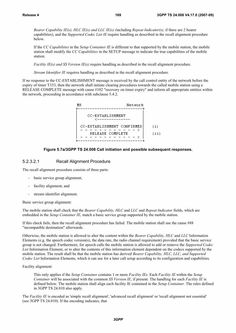
3GPP
3GPP TS 24.008 V4.17.0 (2007-09)Release 4 169
Bearer Capability IE(s), HLC IE(s) and LLC IE(s) (including Repeat Indicator(s), if there are 2 bearercapabilities), and the Supported Codec List IE require handling as described in the recall alignment procedurebelow.
If the CC Capabilities in the Setup Container IE is different to that supported by the mobile station, the mobilestation shall modify the CC Capabilities in the SETUP message to indicate the true capabilities of the mobilestation.
Facility IE(s) and SS Version IE(s) require handling as described in the recall alignment procedure.
Stream Identifier IE requires handling as described in the recall alignment procedure.
If no response to the CC-ESTABLISHMENT message is received by the call control entity of the network before theexpiry of timer T333, then the network shall initiate clearing procedures towards the called mobile station using aRELEASE COMPLETE message with cause #102 "recovery on timer expiry" and inform all appropriate entities withinthe network, proceeding in accordance with subclause 5.4.2.
Figure 5.7a/3GPP TS 24.008 Call initiation and possible subsequent responses.
5.2.3.2.1 Recall Alignment Procedure
The recall alignment procedure consists of three parts:
- basic service group alignment,
- facility alignment, and
- stream identifier alignment.
Basic service group alignment:
The mobile station shall check that the Bearer Capability, HLC and LLC and Repeat Indicator fields, which areembedded in the Setup Container IE, match a basic service group supported by the mobile station.
If this check fails, then the recall alignment procedure has failed. The mobile station shall use the cause #88"incompatible destination" afterwards.
Otherwise, the mobile station is allowed to alter the content within the Bearer Capability, HLC and LLC InformationElements (e.g. the speech codec version(s), the data rate, the radio channel requirement) provided that the basic servicegroup is not changed. Furthermore, for speech calls the mobile station is allowed to add or remove the Supported CodecList Information Element, or to alter the contents of this information element dependent on the codecs supported by themobile station. The result shall be that the mobile station has derived Bearer Capability, HLC, LLC, and SupportedCodec List Information Elements, which it can use for a later call setup according to its configuration and capabilities.
Facility alignment:
This only applies if the Setup Container contains 1 or more Facility IEs. Each Facility IE within the SetupContainer will be associated with the common SS Version IE, if present. The handling for each Facility IE isdefined below. The mobile station shall align each facility IE contained in the Setup Container. The rules definedin 3GPP TS 24.010 also apply.
The Facility IE is encoded as 'simple recall alignment', 'advanced recall alignment' or 'recall alignment not essential'(see 3GPP TS 24.010). If the encoding indicates, that
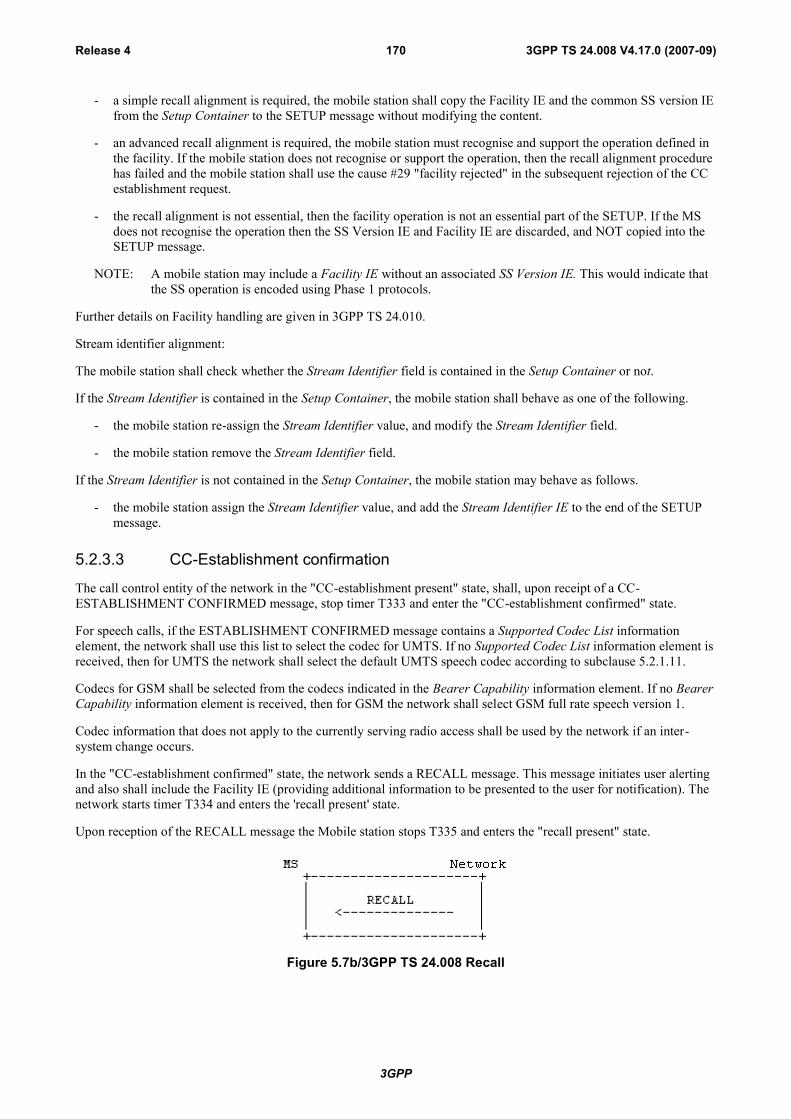
3GPP
3GPP TS 24.008 V4.17.0 (2007-09)Release 4 170
- a simple recall alignment is required, the mobile station shall copy the Facility IE and the common SS version IEfrom the Setup Container to the SETUP message without modifying the content.
- an advanced recall alignment is required, the mobile station must recognise and support the operation defined inthe facility. If the mobile station does not recognise or support the operation, then the recall alignment procedurehas failed and the mobile station shall use the cause #29 "facility rejected" in the subsequent rejection of the CCestablishment request.
- the recall alignment is not essential, then the facility operation is not an essential part of the SETUP. If the MSdoes not recognise the operation then the SS Version IE and Facility IE are discarded, and NOT copied into theSETUP message.
NOTE: A mobile station may include a Facility IE without an associated SS Version IE. This would indicate thatthe SS operation is encoded using Phase 1 protocols.
Further details on Facility handling are given in 3GPP TS 24.010.
Stream identifier alignment:
The mobile station shall check whether the Stream Identifier field is contained in the Setup Container or not.
If the Stream Identifier is contained in the Setup Container, the mobile station shall behave as one of the following.
- the mobile station re-assign the Stream Identifier value, and modify the Stream Identifier field.
- the mobile station remove the Stream Identifier field.
If the Stream Identifier is not contained in the Setup Container, the mobile station may behave as follows.
- the mobile station assign the Stream Identifier value, and add the Stream Identifier IE to the end of the SETUPmessage.
5.2.3.3 CC-Establishment confirmation
The call control entity of the network in the "CC-establishment present" state, shall, upon receipt of a CC-ESTABLISHMENT CONFIRMED message, stop timer T333 and enter the "CC-establishment confirmed" state.
For speech calls, if the ESTABLISHMENT CONFIRMED message contains a Supported Codec List informationelement, the network shall use this list to select the codec for UMTS. If no Supported Codec List information element isreceived, then for UMTS the network shall select the default UMTS speech codec according to subclause 5.2.1.11.
Codecs for GSM shall be selected from the codecs indicated in the Bearer Capability information element. If no BearerCapability information element is received, then for GSM the network shall select GSM full rate speech version 1.
Codec information that does not apply to the currently serving radio access shall be used by the network if an inter-system change occurs.
In the "CC-establishment confirmed" state, the network sends a RECALL message. This message initiates user alertingand also shall include the Facility IE (providing additional information to be presented to the user for notification). Thenetwork starts timer T334 and enters the 'recall present' state.
Upon reception of the RECALL message the Mobile station stops T335 and enters the "recall present" state.
Figure 5.7b/3GPP TS 24.008 Recall

3GPP
3GPP TS 24.008 V4.17.0 (2007-09)Release 4 171
5.2.3.4 Recall present
In the "recall present" state, the call control entity in the mobile station waits for acceptance of the Recall by the user.Once confirmation is received, the mobile station indicates acceptance of a recall by
- sending a SETUP message to its peer entity in the network;
- starting Timer T303; and
- entering the "call initiated" state and proceeding as described in subclause 5.2.1.1.
The MS shall ensure that the contents of the Bearer Capability IE(s) and Supported Codec List IE sent in the SETUPmessage are the same as the Bearer Capability IE(s) and Supported Codec List IE in the previous CC-ESTABLISHMENT CONFIRMED message related to this Network Initiated MO Call.
In the "recall-present" state, if the user of a mobile station is User Determined User Busy then a RELEASECOMPLETE message shall be sent with cause #17 "user busy" In the "recall-present" state. If the user of a mobilestation wishes to reject the recall then a RELEASE COMPLETE message shall be sent with cause #21 "call rejected".
In either case, the mobile shall release the connection in accordance with subclause 5.4.2
On receipt of the SETUP message in the "recall present" state, the network shall stop timer T334 and proceed asspecified in subclause 5.2.1.2.
If the call control entity of the network does not receive a SETUP message before the expiry of timer T334, then thenetwork shall send a RELEASE COMPLETE message to the mobile using cause #102 "recovery on timer expiry",release the MM connection, enter the "null" state and shall inform all appropriate entities within the network.
Figure 5.7b/3GPP TS 24.008 Recall acceptance or rejection by user
5.2.3.5 Traffic channel assignment during network initiated mobile originating callestablishment
It is a network dependent decision whether or not to initiate the assignment of a traffic channel during the "CC-establishment confirmed" state.
5.3 Signalling procedures during the "active" state
5.3.1 User notification procedureThe mobile terminating user notification procedure allows the network to notify a mobile station of any appropriatecall-related event during the "active" state of a call. The procedure consists in the network sending a NOTIFY messageto the mobile station. No state change occurs at any of the interface sides following the sending or the receipt of thismessage (but an appropriate indication may optionally be generated in the mobile station).
The mobile originating notification procedure allows the mobile station to notify the remote user of any appropriatecall-related event during the "active" state of a call by sending a NOTIFY message containing a notification indicator tothe network; upon receipt of this message, the network sends a NOTIFY message containing the same notify indicatorto the other user involved in the call. No state change occurs at any of the interface sides following the sending or thereceipt of this message.

3GPP
3GPP TS 24.008 V4.17.0 (2007-09)Release 4 172
5.3.2 Call rearrangementsCall rearrangements on the radio interface are not supported by explicit messages (e.g. SUSPEND and RESUMEmessages as defined in ETS 300 102-1 [70]). However if a remote non-PLMN user initiates call rearrangements, thenetwork shall inform the mobile station by means of a NOTIFY message. In a similar way the mobile station can informthe network about rearrangements by sending a NOTIFY message (e.g. change of user equipment connected to themobile station).
5.3.3 Codec Change ProcedureDuring a speech call in UMTS, if a mobile station supports more than one UMTS codec, the network can change theUMTS codec via RRC procedures. In order to request the mobile station to change the codec, the network shall send thenew selected codec type in the NAS Synchronisation Indicator IE (RRC protocol), see subclause 5.2.1.11.
5.3.4 Support of Dual ServicesThe behaviour described in this subclause is used to realize the following required services throughout subclause 5.3.4.The mobile station is not obliged to support the network originated in-call modification procedure. In that case, themobile station shall, when receiving a MODIFY message, treat the message as unknown and react as described insubclause 8.4. If the mobile station is already prepared to support the procedure in both directions, it shall act asdescribed in this subclause.
Alternate Speech/Group 3 fax (Teleservice 61 according to 3GPP TS 22.003 [4]).
5.3.4.1 Service Description
This circuit switched service allows the two users on a point-to-point connection to use the connection between themfor different information transfer during the same call, but not at the same time.
If the negotiation during call establishment leads to the recognition of the above mentioned services, the in-callmodification procedure is allowed to be executed within the current call by changing from one call mode to the other.
In some cases the in-call modification procedure makes it necessary to change the channel configuration by allocating anew channel and in other cases to change channel configuration parameters while keeping the previously allocatedchannel. This change is determined by the network, which initiates either the channel assignment procedure, handoverprocedure or channel mode modify procedure (see clause 3).
The capability and the initial mode desired must be identified by the mobile station by identifying each mode ofoperation with a separate information element during call establishment. Further the type of change between the modesmust be identified by means of the repeat indicator:
mode 1 "alternate" mode 2.
5.3.4.2 Call establishment
For both mobile originating and mobile terminating calls, the normal call establishment procedures apply.
5.3.4.2.1 Mobile Originating Establishment
The service is requested by the originating mobile station by transferring a SETUP message to the network containingthe BC repeat indicator IE, the bearer capability 1 information element, and the bearer capability 2 informationelement. The first mode of operation ("call mode") shall be indicated by the bearer capability 1 information elementand the second call mode by the bearer capability 2 information element.
A low layer compatibility may optionally be specified for each call mode in a low layer compatibility I and low layercompatibility II information element. In that case:
- the SETUP message shall contain the LLC repeat indicator IE and both low layer compatibility I and low layercompatibility II information elements. The low layer compatibility I information element then corresponds to thebearer capability 1 information element and the low layer compatibility II information element to the bearercapability 2 information element;
3GPP
3GPP TS 24.008 V4.17.0 (2007-09)Release 4 173
- if no low layer compatibility specification applies for one of the two call modes, the corresponding low layercompatibility IE (low layer compatibility I or low layer compatibility II) shall indicate "not applicable";
- the LLC repeat indicator shall specify the same repeat indication as the BC repeat indicator IE.
Similarly, a high layer compatibility may optionally be specified for each call mode in a high layer compatibility i andhigh layer compatibility ii information element. In that case:
- the SETUP message shall contain the HLC repeat indicator IE and both high layer compatibility i and high layercompatibility ii information elements. The high layer compatibility i information element then corresponds to thebearer capability 1 information element and the high layer compatibility ii information element to the bearercapability 2 information element;
- if no high layer compatibility specification applies for one of the two call modes, the corresponding high layercompatibility IE (high layer compatibility i or high layer compatibility ii) shall indicate "not applicable";
- the HLC repeat indicator shall specify the same repeat indication as the BC repeat indicator IE.
The receiving entity shall ignore whether the LLC repeat indicator IE or HLC repeat indicator are contained in themessage or not; it shall also ignore the repeat indication of an LLC repeat indicator IE or HLC repeat indicator IE. Ifthe low layer compatibility II IE is not contained in the message and the low layer compatibility I IE is contained in themessage, the receiving entity shall relate it to a call mode indicated in the message that does not specify speech (if any).If the high layer compatibility ii IE is not contained in the message and the high layer compatibility i IE is contained inthe message, the receiving entity shall relate it to a call mode indicated in the message that does not specify speech (ifany).
The specific part of the network which is sensitive to the call mode shall examine each mode described in the bearercapabilities included in the SETUP message by performing compatibility checking as defined in Annex B. If as a resultof this compatibility checking the network decides to reject the call, then the network shall initiate call clearing asspecified in subclause 5.4 with the following causes:
a) #57 "bearer capability not authorized";
b) #58 "bearer capability not presently available";
c) #65 "bearer service not implemented";
d) #70 "only restricted digital information bearer capability is available".
5.3.4.2.2 Mobile Terminating Establishment
The service is indicated to the called mobile station by a SETUP message coded in the same manner as in the mobileoriginating call establishment. As specified for normal terminating call establishment, the service may be indicated bythe called mobile station in the CALL CONFIRMED message.
The destination mobile station shall perform the compatibility checking as defined in Annex B for both required modesif indicated in the SETUP message. If as a result of compatibility checking the mobile station decides to reject the call,the mobile station shall initiate call clearing according to the procedures of subclause 5.4 with one of the followingcauses:
a) #57 "bearer capability not authorized";
b) #58 "bearer capability not presently available";
c) #65 "bearer service not implemented";
d) #88 "incompatible destination".
The mobile station may accept the call if the first mode indicated is free irrespective of whether the other mode is freeor busy.
5.3.4.3 Changing the Call Mode
In order to change the call mode, the following in-call modification procedures shall be used.

3GPP
3GPP TS 24.008 V4.17.0 (2007-09)Release 4 174
Either side of the radio interface may act as the requesting user to invoke the in-call modification.
Upon each successful completion of the in-call modification procedure, the call changes to the next mode negotiatedand agreed during the establishment phase of the call.
The in-call modification procedures are completely symmetrical at the radio interface.
NOTE: Considering a possible future evolution, in-call modification is specified as a symmetrical procedure.
5.3.4.3.1 Initiation of in-call modification
The procedure is initiated by the requesting originating side in the "active" state of the call. It shall send a MODIFYmessage including the new mode to be changed to; start timer T323; and enter the "mobile originating modify" state(mobile station side) or the "mobile terminating modify" state (network side). Any internal resources necessary tosupport the next call mode shall be reserved. The new mode given in the MODIFY message shall be one of thosealready negotiated and agreed during the establishment phase of the call. If the data call direction is different from thedirection of the call setup a reverse call setup direction IE shall be included in the MODIFY message; otherwise this IEshall not be included. The MODIFY originating side shall stop sending Bm-channel information; and stop interpretingreceived Bm-channel information according to the old call mode.
Upon receipt of the MODIFY message, the destination side shall check to ensure that the requested call mode can stillbe supported and if so, it shall initiate the reservation of any resources necessary to support the next call mode and enterthe "mobile originating modify" (network side) or "mobile terminating modify" state (mobile station side).
5.3.4.3.2 Successful completion of in-call modification
If the destination network/mobile station receives a MODIFY message with a new mode which is already the actual oneof the call the network/mobile station shall remain in the "active" state; send a MODIFY COMPLETE message with theactual mode; and shall not initiate anything else.
If the requested mode is speech and if during call establishment the network received a Supported Codec List IE, thenetwork shall use this list to select the codec for UMTS. If no Supported Codec List information element is received,then for UMTS the network shall select the default UMTS speech codec according to subclause 5.2.1.11.
Codecs for GSM shall be selected from the codecs indicated in the Bearer Capability information element. If no BearerCapability information element is received, then for GSM the network shall select GSM full rate speech version 1.
If the Supported Codec List IE is received, then the network shall indicate the codec selected for UMTS to the mobilestation via RANAP and RRC protocol in the NAS Synchronisation Indicator IE (see subclause 5.2.1.11).
If the in-call modification was originated by the mobile station, the mobile station and the network shall proceed asfollows:
If the requested mode is not the actual one and can be supported by the network it shall change the channelconfiguration, if required, and step on to any internal resources necessary to support the next call mode. If therequested mode is a data or facsimile mode, it shall also perform the appropriate means to take the direction ofthe data call into account. After successful change of the channel configuration it shall start sending userinformation according to the next call mode and start interpreting received user channel information according tothe next call mode; send a MODIFY COMPLETE message with the new call mode included and enter the"active" state (network side). If the MODIFY message had contained a reverse call setup direction IE, the sameIE shall be included in the MODIFY COMPLETE message.
Upon receipt of the MODIFY COMPLETE message the mobile station shall: initiate the alternation to thoseresources necessary to support the next call mode; stop timer T323; and enter the "active" state (mobile stationside).
If the in-call modification was originated by the network, the mobile station and the network shall proceed as follows:
If the requested mode is not the actual one and can be supported by the mobile station it shall step on to anyinternal resources necessary to support the next call mode. If the requested mode is a data or facsimile mode, itshall also perform the appropriate means to take the direction of the data call into account. The mobile stationshall send a MODIFY COMPLETE message with the new call mode included and enter the "active" state(mobile station side). If the MODIFY message had contained a reverse call setup direction IE, the same IE shallbe included in the MODIFY COMPLETE message.
3GPP
3GPP TS 24.008 V4.17.0 (2007-09)Release 4 175
Upon receipt of the MODIFY COMPLETE message the network shall: change the channel configuration, ifrequired; after successful change of the channel configuration initiate the alternation to those resources necessaryto support the next call mode; stop timer T323; and enter the "active" state (network side).
The mobile station shall start sending user information according to the next call mode and start interpretingreceived user channel information according to the next call mode as soon as a suitable channel for the newmode is available.
In both cases:
For an alternate speech/facsimile group 3 service (refer to subclause 5.3.4) the old resources may still be keptreserved.
The reaction of the originating side if it had included a reverse call setup direction IE in the MODIFY message,but the destination side did not include the IE in the MODIFY COMPLETE message is implementationdependent.
5.3.4.3.3 Change of the channel configuration
In case the requested bearer capability cannot be supported by the current channel configuration the network shallinitiate the assignment procedure and change the channel configuration accordingly.
5.3.4.3.4 Failure of in-call modification
5.3.4.3.4.1 Network rejection of in-call modification
If the network cannot support the change to the requested call mode or if the change of the channel configuration failsthe network shall: release the resources which had been reserved for the alternation: send a MODIFY REJECT messagewith the old bearer capability and with cause # 58 "bearer capability not presently available" to the initiating mobilestation; and enter the "active" state. If the change of the channel configuration fails, the network shall return to theinternal resources required for the old call mode.
Upon receipt of the MODIFY REJECT message with the old bearer capability the initiating mobile station shall: stoptimer T323; release any resources which had been reserved for the alternation; resume sending user channel informationaccording to the present call mode; resume interpreting received user channel information according to the present callmode; and enter the "active" state.
5.3.4.3.4.2 Mobile station rejection of in-call modification
If the mobile station cannot support the change to the requested call mode, the mobile station shall: release anyresources which had been reserved for the alternation; send a MODIFY REJECT message with the old bearer capabilityand cause # 58 "bearer capability not presently available", and enter the "active" state.
Upon receipt of the MODIFY REJECT message the network shall: stop timer T323, release any resources which hadbeen reserved for the alternation.
5.3.4.3.4.3 Time-out recovery
Upon expiration of T323 in either the mobile station or the network the procedures for call clearing shall be initiatedwith cause # 102 "recovery on timer expiry".
5.3.4.4 Abnormal procedures
If a MODIFY, MODIFY COMPLETE or MODIFY REJECT message is received in the "disconnect indication","disconnect request" (mobile station side only) or "release request" state then the received message shall be discardedand no action shall be taken.
If a MODIFY COMPLETE message indicating a call mode which does not correspond to the requested one is receivedor if a MODIFY REJECT message indicating a call mode which does not correspond to the actual one is received thenthe received message shall be discarded and no action shall be taken.

3GPP
3GPP TS 24.008 V4.17.0 (2007-09)Release 4 176
If a MODIFY message indicating a call mode which does not belong to those negotiated and agreed during theestablishment phase of the call, is received, then a MODIFY REJECT message with the actual call mode and with cause# 57 "bearer capability not authorized" shall be sent back.
Figure 5.10a/3GPP TS 24.008 In-call modification sequence initiated by MS
Figure 5.10b/3GPP TS 24.008 In-call modification sequence initiated by network
5.3.5 User initiated service level up- and downgrading (GSM only)The user initiated service level up- and downgrading is applicable for non-transparent multislot data services, only. Bymeans of this procedure the user can request a change of the "maximum number of traffic channels" and/or "wanted airinterface user rate" parameters, to be assigned by the network.
5.3.5.1 Initiation of service level up- and downgrading
The procedure is initiated by the mobile station in the "active" state of the call. It shall:
- send a MODIFY message including the wanted value of the "maximum number of traffic channels" and/or the"wanted air interface user rate" parameters;
- not change any of the other, possibly negotiated, parameters of the bearer capability information element;
- start timer T323; and
- enter the "mobile originating modify" state.
Any internal resources necessary to support the next service parameters shall be reserved. If a dual service wasnegotiated at call setup, the mobile station shall initiate the service level up- or down-grading only during the data phaseof the dual service.
Upon receipt of the MODIFY message, the network shall check if the indicated maximum number of traffic channelscan be supported and enter the "mobile originating modify" state.
5.3.5.2 Successful completion of service level up- and downgrading
The network may upon reception of the MODIFY message initiate a change of the channel configuration assigned tothe mobile station.

3GPP
3GPP TS 24.008 V4.17.0 (2007-09)Release 4 177
As a response to the MODIFY message the network sends a MODIFY COMPLETE message including the bearercapability negotiated at call setup and enters the "active" state.
Upon receipt of the MODIFY COMPLETE message the mobile station shall stop timer T323 and enter the "active"state.
5.3.5.3 Rejection of service level up- and downgrading
If a change of bearer service is requested together with a change of the "maximum number of traffic channels" and/orthe "wanted air interface user rate", or if the current used service is not a data service where up- and downgrading isapplicable, or if the receiver chooses not to grant the request, the network shall:
- send a MODIFY REJECT message with bearer capability negotiated at call setup and with cause #58 "bearercapability not presently available";
- enter the "active" state.
Upon receipt of the MODIFY REJECT message with the bearer capability negotiated at call setup, the mobile stationshall: stop timer T323 and enter the "active" state.
5.3.5.4 Time-out recovery
Upon expiration of T323 in the mobile station the procedures for call clearing shall be initiated with cause #102"recovery on timer expiry".
5.3.6 Support of multimedia calls
5.3.6.1 Service description
The GSM-UMTS circuit-switched multimedia call is based on the 3G-324M [26.111], which is a 3GPP-variant of theITU-T H.324 recommendation. CS Multimedia telephony is a Bearer Service, which utilizes the SynchronousTransparent Data service (BS30) [3].
At the multimedia call setup the required call type, 3G-324M, is indicated, for the network to be able to invokeappropriate interworking functionality. In the peer end the H.324 information is used to invoke the terminal application.In addition to H.324 indication the terminal must select Information Transfer Capability (ITC) for the multimedia call.The 'correct' ITC depends on the peer end and the transporting networks; an all-ISDN call is a UDI/RDI call, and a call,which involves PSTN, is an analog "3.1 kHz audio" call.
For the case when the setup of a multimedia call is not successful, fallback to speech is specified.
5.3.6.2 Call establishment
For both mobile originating and mobile terminating calls, the normal call establishment procedures apply, with theexceptions specified in the following subclauses.
For further description of the function of MSC/IWF in the following clauses, see 3GPP TS 29.007 [38].
5.3.6.2.1 Mobile originated multimedia call establishment
At call setup the required call type, 3G-324M, is indicated by the originating MS in the SETUP message, with thebearer capabilityIE parameter Other Rate Adaptation set to "H.223 and H.245". The support of a fallback to speech isrequested by including also a bearer capabilityIE 2 with speech indication in the SETUP message. The network shallexamine each mode described in the bearer capability IEs included in the SETUP message by performing compatibilitychecking as defined in annex B. If as a result of this compatibility checking the network decides to reject the call, thenthe network shall initiate call clearing as specified in subclause 5.4 with the following causes:
a) #57 "bearer capability not authorized";
b) #58 "bearer capability not presently available";
c) #65 "bearer service not implemented";
3GPP
3GPP TS 24.008 V4.17.0 (2007-09)Release 4 178
d) #70 "only restricted digital information bearer capability is available".
If the MS requested for a multimedia call with fallback to speech, and the network accepts the call, the network has thefollowing options for the inclusion of bearer capability IEs in the CALL PROCEEDING message:
- if the network accepts the requested multimedia call and supports fallback to speech, both multimedia andspeech bearer capability IEs shall be included;
- if the network accepts a multimedia (only) call, a multimedia bearer capability IE shall be included;
- if the network accepts a speech (only) call, a speech bearer capability IE shall be included.
If the MS requested for a multimedia call only, and the network accepts the call, the network shall always include asingle multimedia bearer capability IE in the CALL PROCEEDING message.
The originating user shall determine (possibly by pre-configuration of the terminal) whether a digital connection isrequired or if the call will be an analog modem call. If the call is expected to be digital the bearer capability IEparameter ITC is set to UDI/RDI. In an analog call the bearer capability IE parameter ITC is set to "3,1 kHz audio exPLMN". Additionally required modem type is indicated (Other Modem Type = V.34).
5.3.6.2.1.1 Fallback to speech
If the network, during setup of an analogue H.324-call, detects that the called end does not support a H.324 call, thennetwork initiates the in-call modification procedure (see subclause 5.3.4.3) towards the MS to modify the call mode tospeech, if the MS had included a speech bearer capability IE in the SETUP message.
NOTE: Fallback from digital (UDI) H.324-call to speech is not supported.
5.3.6.2.2 Mobile terminating multimedia call
At call setup the required call type, 3G-324M, is indicated by the network in the SETUP message, with the bearercapability IE parameter Other Rate Adaptation set to 'H.223 and H.245'. ITC is either '3,1 kHz audio ex PLMN' or'UDI/RDI'. If the network supports fallback to speech, and if the subscriber has subscription to speech, a bearercapability IE 2 with speech indication is included in the SETUP message. The bearer capabilityIE(s) may (in the caseof the single numbering scheme) be missing from the SETUP-message.
The MS shall perform the compatibility checking as defined in Annex B for the required mode(s) if indicated in theSETUP message. If as a result of compatibility checking the MS decides to reject the call, the MS shall initiate callclearing according to the procedures of subclause 5.4 with one of the following causes:
a) #57 "bearer capability not authorized";
b) #58 "bearer capability not presently available";
c) #65 "bearer service not implemented";
d) #88 "incompatible destination".
The MS shall indicate the supported call type(s) in the CALL_CONFIRMED-message, which is the acknowledgementto SETUP. If the network offered a multimedia call with fallback to speech, the MS has the following options for theinclusion of bearer capability IEs in the CALL_CONFIRMED message:
- if the MS/user accepts the offered multimedia call, and supports speech fallback both multimedia and speechbearer capability IEs shall be included;
- if the MS/user accepts the offered multimedia call, but does not support speech fallback only, a multimediabearer capability IE shall be included;
- if the MS/user wishes a speech (only) call a speech bearer capability IE shall be included.
If the network offered a multimedia call only, and the MS/user accepts the call, the MS shall always include a singlemultimedia bearer capability IE in the CALL CONFIRMED message.
3GPP
3GPP TS 24.008 V4.17.0 (2007-09)Release 4 179
If the SETUP contained no bearer capability IE the network shall perform compatibility checking of the CALLCONFIRMED message in the same way as the compatibility checking of the SETUP message in the mobile originatingcall case, described in subclause 5.3.6.2.1.
If modem handshaking fails (in a modem call) the call mode will be modified to speech. The modem signalling isinband, so the call must have reached the active state, when these conclusions about the presence of modems can bedone. The call modifications are realized through the in-call modification procedure, by which the network requests theMS to modify the call mode (see subclause 5.3.4.3).
NOTE: Fallback from digital (UDI) H.324-call to speech is not supported.
5.3.6.3 In-call modification in the "active" state
The in-call modification procedure as specified in subclause 5.3.4.3 shall be used. Following bearer capabilityparameters can be modified with the procedure (see 3GPP TS 29.007 [38]):
- Fixed Network User Rate
Only network side of the radio interface may act as the requesting user to invoke the in-call modification.
5.3.6.3.1 Void
5.3.6.3.2 Void
5.3.6.3.3 Void
5.3.6.3.3.1 Void
5.3.6.3.3.2 Void
5.4 Call clearing
5.4.1 TerminologyThe following terms are used in the present document in the description of clearing procedures:
- A traffic channel (see 3GPP TS 44.003 [16]) is "connected" when the channel is part of a circuit-switchedconnection established according to the present document.
- A traffic channel is "disconnected" when the channel is no longer part of a circuit-switched connection, but is notyet available for use in a new connection.
5.4.2 Exception conditionsUnder normal conditions, the call control entity of the mobile station or of the network initiates call clearing by sendinga DISCONNECT message to its peer entity; then both entities follow the procedures defined in subclauses 5.4.3 and5.4.4 respectively.
As an exception to the above rule, the call control entity of the mobile station or of the network, in response to a SETUPor START CC or CC-ESTABLISHMENT CC-ESTABLISHMENT CONFIRMED or RECALL message, can reject acall by stopping all running call control timers, responding with a RELEASE COMPLETE message, releasing the MMconnection, and returning to the "null" state, provided no other response has previously been sent.
As a further exception, the call control entity of the network may initiate call clearing by stopping all running callcontrol timers, sending a RELEASE message, starting timer T308, and entering the "release request" state.
NOTE: This way to initiate call clearing by sending a RELEASE message should not be used by the network:
- if in-band tones/announcements are provided and the network decides to use the procedure describedin subclause 5.4.4.1.1.1 or 5.4.4.2.1;
3GPP
3GPP TS 24.008 V4.17.0 (2007-09)Release 4 180
- if the network wants to have the opportunity to respond to information sent by the mobile stationduring call clearing, e.g. when the network indicates that "CCBS activation is possible".
A call control entity shall accept an incoming RELEASE COMPLETE message used to initiate the call clearing eventhough the cause information element is not included.
A control entity shall accept an incoming RELEASE message used to initiate the call clearing even though the causeinformation element is not included.
Furthermore, a call control entity shall regard an incoming RELEASE COMPLETE message as consistent with any ofits states; a call control entity shall regard an incoming RELEASE message as consistent with any of its states exceptthe null state: a call control entity of the mobile station shall regard an incoming DISCONNECT message as consistentwith any of its call control states except the "null" state, the "release request" state, and the "disconnect indication" state;a call control entity of the network shall regard an incoming DISCONNECT message as consistent with any of its callcontrol states except the "null" state and the "release request" state.
NOTE: This allows the introduction of shorter call clearing procedures in the future.
5.4.3 Clearing initiated by the mobile station
5.4.3.1 Initiation of call clearing
Apart from the exceptions identified in subclause 5.4.2, the call control entity of the mobile station shall initiate clearingby: stopping all running call control timers, sending a DISCONNECT message; starting timer T305; and entering the"disconnect request" state.
5.4.3.2 Receipt of a DISCONNECT message from the mobile station.
The call control entity in the network in any state except the "null" state and the "release request" state shall, uponreceipt of a DISCONNECT message:
- Stop all running call control timers;
- initiate procedures to clear the network connection and the call to the remote user;
- send a RELEASE message to its peer entity;
- start timer T308; and
- enter the "release request" state.
NOTE: The RELEASE message has only local significance and does not imply an acknowledgement of clearingfrom the remote user.
5.4.3.3 Receipt of a RELEASE message from the network
The call control entity of the mobile station in any state except the "null" state and the "release request" state, shall,upon receipt of a RELEASE message: stop all running call control timers; send a RELEASE COMPLETE message;release the MM connection; and return to the "null" state.
5.4.3.4 Receipt of a RELEASE COMPLETE message from the mobile station
A call control entity of the network in any call control state shall, upon receipt of a RELEASE COMPLETE messagefrom its peer entity in the mobile station: stop all running call control timers; release the MM connection; and return tothe "null" state.
5.4.3.5 Abnormal cases
The call control entity of the mobile station in the "disconnect request" state, shall upon expiry of timer T305: send aRELEASE message to the network with the cause number originally contained in the DISCONNECT message andoptionally, a second cause information element with cause #102 "recovery on timer expiry", start timer T308, and enterthe "release request" state.

3GPP
3GPP TS 24.008 V4.17.0 (2007-09)Release 4 181
The call control entity of the network in the "release request" state, shall, at first expiry of timer T308, retransmit theRELEASE message, start timer T308, and stay in the "release request" state. At second expiry of timer T308, the callcontrol entity of the network shall: release the MM connection; and return to the "null" state.
5.4.4 Clearing initiated by the networkApart from the exception conditions identified in subclause 5.4.2, the call control entity of the network shall initiateclearing by: sending a DISCONNECT message; and entering the "disconnect indication" state. The DISCONNECTmessage is a local invitation to clear the call.
NOTE: When the network initiates clearing by sending a RELEASE message, the procedures described insubclauses 5.4.3., 5.4.3.4 and 5.4.3.5 are followed.
A mobile station that does not support the "Prolonged Clearing Procedure" shall comply with the requirements ofsubclause 5.4.4.1 and shall ignore subclause 5.4.4.2. A mobile station that supports the "Prolonged Clearing Procedure"shall comply with the requirements of subclauses 5.4.4.2 and shall ignore subclause 5.4.4.1.
5.4.4.1 Clearing initiated by the network: mobile does not support "ProlongedClearing Procedure"
Sublause 5.4.4.1 only applies to mobile stations that do not support the "Prolonged Clearing Procedure" option.
5.4.4.1.1 Clearing when tones/announcements provided
When in-band tones/announcements are provided (see subclause 5.5.1), the call control entity of the network mayinitiate clearing by sending a DISCONNECT message containing progress indicator #8 "in-band information orappropriate pattern now available", starting timer T306, and entering the "disconnect indication" state.
5.4.4.1.1.1 Receipt of a DISCONNECT message with progress indicator #8 from the network
The call control entity of the MS in any state except the "null" state, the "disconnect indication" state, and the "releaserequest" state, shall, upon receipt of a DISCONNECT message with progress indicator #8:
i) if an appropriate speech traffic channel is not connected, continue clearing as defined in subclause 5.4.4.1.2.1without connecting to the in-band tone/announcement;
ii) if an appropriate speech traffic channel is connected, attach the user connection for speech if it is not yet attachedand enter the "disconnect indication" state. In that state, if upper layers request the clearing of the call, the callcontrol entity of the MS shall proceed as defined in subclause 5.4.4.1.2.1.
5.4.4.1.1.2 Expiry of timer T306
The call control entity of the network, having entered the "disconnect indication" state after sending a disconnectmessage with the progress indicator #8, shall, upon expiry of timer T306, continue clearing by sending a RELEASEmessage with the cause number originally contained in the DISCONNECT message; starting timer T308; and enteringthe "release request" state.
5.4.4.1.2 Clearing when tones/announcements not provided
When in-band tones and announcements are not provided, the call control entity of the network shall initiate callclearing by stopping all running call control timers, sending a DISCONNECT message without progress indicator,starting timer T305 and entering the "disconnect indication" state.

3GPP
3GPP TS 24.008 V4.17.0 (2007-09)Release 4 182
5.4.4.1.2.1 Receipt of a DISCONNECT message without progress indicator or with progressindicator different from #8 from the network
The call control entity of the mobile station in any state except the "null" state, the "disconnect indication" state, and the"release request" state, shall, upon the receipt of a DISCONNECT message without progress indicator informationelement or with progress indicator different from #8:
- stop all running call control timers;
- send a RELEASE message;
- start timer T308; and
- enter the "release request" state.
5.4.4.1.2.2 Receipt of a RELEASE message from the mobile station
The call control entity of the network in any state except the "null" state and the "release request" state, shall, uponreceipt of a RELEASE message: stop all running call control timers; send a RELEASE COMPLETE message; releasethe MM connection; and return to the "null" state.
5.4.4.1.2.3 Abnormal cases
The call control entity of the network, having entered the "disconnect indication" state after sending a DISCONNECTmessage without progress indicator or with progress indicator different from #8, shall upon expiry of timer T305: send aRELEASE message to the mobile station with the cause number originally contained in the DISCONNECT message;start timer T308; and enter the "release request" state. In addition to the original clearing cause, the RELEASE messagemay contain a second cause information element with cause #102 "recovery on timer expiry".
5.4.4.1.3 Completion of clearing
A call control entity of the mobile station in any call control state shall, upon receipt of a RELEASE COMPLETEmessage from its peer entity in the network: stop all running call control timers; release the MM connection; and returnto the "null" state.
5.4.4.1.3.1 Abnormal cases
The call control entity of the mobile station in the "release request" state shall at first expiry of timer T308 retransmitthe RELEASE message and restart timer T308. At second expiry of timer T308, the call control entity of the mobilestation shall: release the MM connection; and return to the "null" state.
5.4.4.2 Clearing initiated by the network: mobile supports "Prolonged ClearingProcedure"
Sublause 5.4.4.2 only applies to mobile stations that support the "Prolonged Clearing Procedure" option.
5.4.4.2.1 Clearing when tones/announcements provided and the network does not indicatethat "CCBS activation is possible"
When in-band tones/announcements are provided (see subclause 5.5.1) and CCBS is not applicable, the call controlentity of the network may initiate clearing by sending a DISCONNECT message containing progress indicator #8 "in-band information or appropriate pattern now available", either not containing an Allowed Actions IE or containing anAllowed Actions IE indicating "CCBS activation is not possible", starting timer T306, and entering the "disconnectindication" state.
3GPP
3GPP TS 24.008 V4.17.0 (2007-09)Release 4 183
5.4.4.2.1.1 Receipt of a DISCONNECT message
The call control entity of the MS in any state except the "null" state, the "disconnect indication" state, and the "releaserequest" state, shall, upon receipt of a DISCONNECT message with progress indicator #8 and, either not containing anAllowed Actions IE or containing an Allowed Actions IE indicating "CCBS activation is not possible":
i) if an appropriate speech traffic channel is not connected,
- stop all running call control timers;
- send a RELEASE message;
- start timer T308;
- enter the "release request" state; and
- not connect to the in-band tone/announcement.
ii) if an appropriate speech traffic channel is connected, attach the user connection for speech if it is not yet attachedand enter the "disconnect indication" state. In that state, if upper layers request the clearing of the call, the callcontrol entity of the MS shall:
- stop all running call control timers;
- send a RELEASE message;
- start timer T308; and
- enter the "release request" state.
5.4.4.2.1.2 Expiry of timer T306
The call control entity of the network, having entered the "disconnect indication, shall, upon expiry of timer T306,continue clearing by sending a RELEASE message with the cause number originally contained in the DISCONNECTmessage; starting timer T308; and entering the "release request" state.
5.4.4.2.2 Clearing when the network indicates that "CCBS activation is possible"
When Activation of CCBS is possible, the call control entity of the network may initiate clearing by sending aDISCONNECT message containing the Allowed Actions IE with an indication that "Activation of CCBS is possible"and starting T338. Optionally, progress indicator #8 "in-band information or appropriate pattern now available" mayalso be contained in the DISCONNECT message (in which case, T338 shall not be greater than T306).
5.4.4.2.2.1 Receipt of a DISCONNECT
Relative to the current state the following procedures apply:
- The call control entity of the MS in the "null" state, the "disconnect indication" state and the "release request"state, shall, upon receipt of a DISCONNECT message react as described in clause 8.
- The call control entity of the MS in the "disconnect request" state, shall, upon receipt of a DISCONNECTmessage:
- stop all running call control timers;
- send a RELEASE message;
- start timer T308; and
- enter the "release request" state.
- The call control entity of the MS in any other states, shall, upon receipt of a DISCONNECT message with anAllowed Actions IE indicating "Activation of CCBS is possible" pass the "Activation of CCBS is possible"indication to the upper layer, enter the "disconnect indication" state, stop all running call control timers and awaita response from the upper layers.
3GPP
3GPP TS 24.008 V4.17.0 (2007-09)Release 4 184
If the DISCONNECT message contained the progress indicator #8 "in-band information or appropriate pattern nowavailable" and an appropriate speech traffic channel is connected, then the MS shall attach the user connection forspeech if it is not yet attached. If the DISCONNECT message did not contain the progress indicator #8 "in-bandinformation or appropriate pattern now available" any connected speech traffic channel shall be disconnected.
Response from the upper layers:
i) If the upper layers request the clearing of the call, the call control entity of the MS shall:
- stop all running call control timers;
- send a RELEASE message;
- start timer T308; and
- enter the "release request" state.
ii) If the upper layers request that the "CCBS activation is to be attempted" then the MS shall
- send a RELEASE message containing a Facility IE including an
- Invoke=CCBSRequest to the network;
- stop all running call control timers;
- start timer T308; and
- enter the "release request" state.
If an appropriate speech traffic channel is connected, transmission of this RELEASE message shall not cause itto be disconnected.
5.4.4.2.2.2 Expiry of timer T338
The call control entity of the network, having entered the "disconnect indication" state after sending a DISCONNECTmessage with an Allowed Actions IE indicating "Activation of CCBS is possible" shall, upon expiry of timer T338,continue clearing by sending a RELEASE message with the cause number originally contained in the DISCONNECTmessage; starting timer T308; and entering the "release request" state.
5.4.4.2.3 Clearing when tones/announcements are not provided and the network does notindicate that "CCBS activation is possible"
When in-band tones and announcements are not provided, and, the network does not wish to indicate in the AllowedActions IE that "CCBS is possible", the call control entity of the network shall initiate call clearing by stopping allrunning call control timers, sending a DISCONNECT message without progress indicator, either without the AllowedActions IE or with the Allowed Actions IE indicating that "CCBS is not possible", starting timer T305 and entering the"disconnect indication" state.
5.4.4.2.3.1 Receipt of a DISCONNECT message
The call control entity of the mobile station in any state except the "null" state, the "disconnect indication" state, and the"release request" state, shall, upon the receipt of a DISCONNECT message either without progress indicatorinformation element or with progress indicator different from #8, and, either without the Allowed Actions IE or with theAllowed Actions IE indicating that "CCBS is not possible":
- stop all running call control timers;
- send a RELEASE message;
- start timer T308; and
- enter the "release request" state.
3GPP
3GPP TS 24.008 V4.17.0 (2007-09)Release 4 185
5.4.4.2.3.2 Abnormal cases
The call control entity of the network, having entered the "disconnect indication", shall upon expiry of timer T305: senda RELEASE message to the mobile station with the cause number originally contained in the DISCONNECT message;start timer T308; and enter the "release request" state.
5.4.4.2.4 Receipt of a RELEASE message from the mobile station
5.4.4.2.4.1 Release, CCBS not requested
For a network that does not support the "CCBS activation" option:
The call control entity of the network in any state except the "null" state and the "release request" state, shall,upon receipt of a RELEASE message: stop all running call control timers; send a RELEASE COMPLETEmessage; release the MM connection; and return to the "null" state.
For a network that does support the "CCBS activation" option:
The call control entity of the network in any state except the "null" state and the "release request" state, shall,upon receipt of a RELEASE message without a Facility IE including an Invoke=CCBSRequest: stop all runningcall control timers; send a RELEASE COMPLETE message; release the MM connection; and return to the "null"state.
5.4.4.2.4.2 Release, CCBS Requested
For a network that does not support the "CCBS activation" option:
The call control entity of the network in any state except the "null" state and the "release request" state, shall,upon receipt of a RELEASE message: stop all running call control timers; send a RELEASE COMPLETEmessage; release the MM connection; and return to the "null" state.
For a network that does support the "CCBS activation" option:
The call control entity of the network in any state except the "null" state and the "release request" state, shall,upon receipt of a RELEASE message containing a Facility IE including an Invoke=CCBSRequest: stop allrunning call control timers; then attempt to activate the recall; then send a RELEASE COMPLETE messageindicating the success or failure of the recall activation attempt; release the MM connection; and return to the"null" state.
5.4.4.2.5 Completion of clearing
A call control entity of the mobile station in any call control state shall, upon receipt of a RELEASE COMPLETEmessage from its peer entity in the network: stop all running call control timers; release the MM connection; and returnto the "null" state.
5.4.4.2.5.1 Abnormal cases
The call control entity of the mobile station in the "release request" state shall at first expiry of timer T308 retransmitthe RELEASE message and restart timer T308. At second expiry of timer T308, the call control entity of the mobilestation shall: release the MM connection; and return to the "null" state.
The retransmitted RELEASE message need not contain the Facility IE including an Invoke=CCBSRequest, even if theoriginal RELEASE message did contain this IE.5.4.5Clear collision
Clear collision occurs when both the mobile station and the network simultaneously transfer DISCONNECT messagesspecifying the same call.
The behaviour of the network call control entity receiving a DISCONNECT message whilst in the "disconnectindication" state is specified in subclause 5.4.3. The behaviour of the MS call control entity receiving a DISCONNECTmessage whilst in the "disconnect request" state is defined in subclause 5.4.4.

3GPP
3GPP TS 24.008 V4.17.0 (2007-09)Release 4 186
Clear collision can also occur when both sides simultaneously transfer RELEASE messages related to the same call.The entity receiving such a RELEASE message whilst within the "release request" state shall: stop timer T308; releasethe MM connection; and enter the "null" state (without sending a RELEASE COMPLETE message).
5.5 Miscellaneous procedures
5.5.1 In-band tones and announcementsWhen the network wants to make the mobile station attach the user connection (e.g. in order to provide in-bandtones/announcement) before the mobile station has reached the "active" state of a call, the network may include aprogress indicator IE indicating user attachment in a suitable CC message:
- Either it includes the IE in a SETUP, CALL PROCEEDING, ALERTING, or CONNECT message that is sendduring call establishment
- it sends a PROGRESS message containing the IE.
A progress indicator IE indicates user attachment if it specifies a progress description in the set {1, 2, 3} or in the set{6, 7, 8, ..., 20}.
On reception of a SETUP, CALL PROCEEDING, ALERTING, CONNECT, or PROGRESS message the mobilestation shall proceed as specified elsewhere in clause 5; if the progress indicator IE indicated user attachment and aspeech mode traffic channel is appropriate for the call the mobile station shall in addition: attach the user connection forspeech as soon as an appropriate channel in speech mode is available. (If a new order to attach the user connection isreceived before the attachment has been performed, the new order shall supersede the previous one.)
Under certain conditions the MS will have to attach the user connection before the CONNECT message. It is up to thenetwork to ensure that no undesired end-to-end through connection takes place during the establishment of a MT call.
NOTE: This allows the use of progress indicator IEs independently from the channel modes appropriate for thecall.
5.5.2 Call collisionsCall collisions as such cannot occur at the network. Any simultaneous mobile originating or mobile terminating callsare dealt with separately assigned and different transaction identifiers.
5.5.3 Status procedures
5.5.3.1 Status enquiry procedure
Whenever a call control entity wishes to check the call state of its peer entity, it may initiate the status enquiryprocedure.
NOTE: This may, in particular, apply to procedural error conditions described in clause 8.
A call control entity initiates the status enquiry procedure by sending the STATUS ENQUIRY message and startingtimer T322. While timer T322 is running, the call control entity shall not send further STATUS ENQUIRY messages.
Upon receipt of a STATUS ENQUIRY message, the receiver shall respond with a STATUS message, reporting thecurrent call state and cause value #30 "response to STATUS ENQUIRY". Receipt of the STATUS ENQUIRY shall notresult in a state change relating to any protocol and connection of the receiver.
If a STATUS message is received that contains cause value #30 "response to status enquiry", timer T322 shall bestopped and further appropriate actions taken, based on the information in that STATUS message, relative to the currentstate of the receiver of the STATUS message. These further "appropriate actions" are implementation dependent.However, the actions prescribed in subclause 5.5.3.2 shall apply.
If a clearing message is received while timer T322 is running, timer T322 shall be stopped, and call clearing shallcontinue.
3GPP
3GPP TS 24.008 V4.17.0 (2007-09)Release 4 187
If timer T322 expires, the STATUS ENQUIRY message may be retransmitted maximally once. If T322 expires afterthe STATUS ENQUIRY has been transmitted the maximum number of times, clearing of the call shall be initiated withcause value #41, "temporary failure", in the first call clearing message.
5.5.3.2 Reception of a STATUS message by a CC entity
5.5.3.2.1 STATUS message with incompatible state
On receipt of a STATUS message reporting an incompatible call control state, the receiving entity shall clear the call bysending a RELEASE COMPLETE message with cause # 101 "message not compatible with protocol state". Thereported call control state is incompatible if the combination of call control states at the sender and receiver side cannotoccur, do not match or cannot be aligned by actions of the receiver; the exact definition is implementation dependent.
5.5.3.2.2 STATUS message with compatible state
A STATUS message may be received indicating a compatible call state but containing one of the following causes:
# 95 "semantically incorrect message"; or
# 96 "invalid mandatory information"; or
# 97 "message type non-existent or not implemented"; or
# 98 "message type not compatible with protocol state"; or
# 99 "information element non-existent or not implemented"; or
# 100 "conditional IE error".
This indicates that the transmitter of the STATUS message was unable to accept some information sent by the recipientof the STATUS message. This allow the recipient to retransmit some or all of the information. Other actions arepossible and are implementation dependent; they may include releasing the call.
5.5.4 Call re-establishment, mobile station sideThis subclause describes the internal handling in the mobile station as far as call control is concerned.
5.5.4.1 Indication from the mobility management sublayer
When a MM connection is active, an indication may be given by the MM sublayer to the call control entity to announcethat the current MM connection has been interrupted but might be re-established on request of call control.
5.5.4.2 Reaction of call control
Depending whether call re-establishment is allowed or not and on its actual state, call control shall decide to eitherrequest re-establishment or to release the MM connection.
a) Re-establishment not required
If the call is in the call establishment or call clearing phase, i.e. any state other than the "active" state or the"mobile originating modify" state, call control shall release the MM connection
b) Re-establishment required
If the call is in the "active" state or "mobile originating modify" state, the indication from MM that re-establishment is possible shall cause call control to request re-establishment from the MM connection,suspend any further message to be sent and await the completion of the re-establishment procedure.
5.5.4.3 Completion of re-establishment
Call Control is notified when the MM connection is re-established and shall then resume the transmission of possiblysuspended messages and resume user data exchange when an appropriate channel is available.

3GPP
3GPP TS 24.008 V4.17.0 (2007-09)Release 4 188
5.5.4.4 Unsuccessful outcome
If the attempt to re-establish the connection was unsuccessful, the MM connection will be released and a releaseindication will be given to call control, see subclause 4.5.1.6.
5.5.5 Call re-establishment, network sideThis subclause describes the handling in the network as far as call control is concerned.
5.5.5.1 State alignment
After a successful call re-establishment it is a network responsibility to identify (e.g. by using the status enquiryprocedure, if needed, and resolve, if possible, any call state or auxiliary state mismatch between the network and themobile station.
5.5.6 ProgressAt any time during the establishment or release of a call and during an active call the network may send a PROGRESSmessage to the mobile station.
On receipt of a PROGRESS message during the establishment or release of a call the mobile station shall stop all callcontrol timers related to that call.
NOTE: If the PROGRESS has been received before the receipt of a CALL PROCEEDING message, the mobilestation will not start timer T310 on receipt of a CALL PROCEEDING message, see subclause 5.2.1.1.3.
Figure 5.11/3GPP TS 24.008 Progress
5.5.7 DTMF protocol control procedureDual Tone Multi Frequency (DTMF) is an inband one out of four plus one out of four signalling system primarily usedfrom terminal instruments in telecommunication networks. The support of DTMF in the network is described in3GPP TS 23.014.
The mobile station shall be capable of transmitting DTMF messages if and only if the mobile station has the userconnection for speech attached and an appropriate channel is available.
The transaction identifier used by the DTMF messages shall be that of the attached speech call.
NOTE 1: The present document means that DTMF messages can generally be sent in the active state of a call inspeech transmission mode or when a traffic channel is available during setup or release and the progressindicator IE has been received.
NOTE 2: Since the DTMF protocol messages are sent in a store and forward mode on the signalling channels thecontrol of the device at the far end may be delayed dependent on the load or quality of the channels.
NOTE 3: The procedures described in this paragraph support DTMF only in the direction mobile station tonetwork.
5.5.7.1 Start DTMF request by the mobile station
A user may cause a DTMF tone to be generated e.g. by depression of a key in the mobile station. The relevant action isinterpreted by the mobile station as a requirement for a DTMF digit to be sent in a START DTMF message on anestablished FACCH. This message contains the value of the digit to be transmitted (0, 1, ..., 9, A, B, C, D, *, #).
Only a single digit will be transferred in each START DTMF message.

3GPP
3GPP TS 24.008 V4.17.0 (2007-09)Release 4 189
On sending a START DTMF message the MS shall start timer T336.
Where a previous START DTMF message has been sent, another START DTMF message shall only be sent by the MSfollowing receipt of its STOP DTMF ACKNOWLEDGE message (see subclause 5.5.7.4) or a START DTMF REJECTmessage from the network (see subclause 5.5.7.2) or following the expiry of timers T336 and T337.
If timer T336 expires, the MS shall terminate the ongoing DTMF procedure without any retransmissions, and is free tobegin another DTMF procedure (e.g. another START DTMF message).
5.5.7.2 Start DTMF response by the network
Upon receiving the START DTMF message the network shall either:
- convert the received digit into a DTMF tone which is applied toward the remote user or;
- send the DTMF digit as an out-of-band message (see 3GPP TS 23.205 [92]),
and return a START DTMF ACKNOWLEDGE message to the mobile station. This acknowledgement may be used inthe mobile station to generate an indication as a feedback for a successful transmission.
If the network cannot accept the START DTMF message a START DTMF REJECT message will be sent to the mobilestation. Upon receipt of a START DTMF ACK message or a START DTMF REJECT message, the MS shall stop timerT336.
5.5.7.3 Stop DTMF request by the mobile station
When the user indicates that the DTMF sending should cease e.g. by releasing the key the mobile station will send aSTOP DTMF message to the network.
On sending a STOP DTMF message the MS shall start timer T337.
The MS shall only send a STOP DTMF message if a START DTMF ACKNOWLEDGE message has been receivedfrom the network (see subclause 5.5.7.2).
If timer T337 expires, the MS shall terminate the ongoing DTMF procedure without any retransmissions, and is free tobegin another DTMF procedure. (e.g. another START DTMF message).
5.5.7.4 Stop DTMF response by the network
Upon receiving the STOP DTMF message the network shall either:
- stop sending the DTMF tone if applied by the network or;
- initiate a suitable out-of-band message (see 3GPP TS 23.205 [92]),
and return a STOP DTMF ACKNOWLEDGE message to the mobile station. Upon receipt of a STOP DTMFACKNOWLEDGE message, the MS shall stop timer T337.
5.5.7.5 Sequencing of subsequent start DTMF requests by the mobile station
If the network is generating DTMF tones it shall ensure that the minimum length of tone and the minimum gap betweentwo subsequent tones (according to ETR 206) is achieved.
NOTE 1: In ETR 206 the minimum duration of a DTMF tone is 70ms ±5ms.
NOTE 2: In ETR 206 the minimum gap between DTMF tones is 65ms.
There is no defined maximum length to the tone, which will normally cease when a STOP DTMF message is receivedfrom the MS. However, the operator may choose to put a pre-defined time limit on the duration of tones sent.
The appropriate sequencing of DTMF control messages is shown in figures 5.8 and 5.9.
NOTE 3: The network may implement the time limit option where the DTMF tone duration is controlled by thenetwork irrespective of the receipt of a STOP DTMF message from the mobile station.
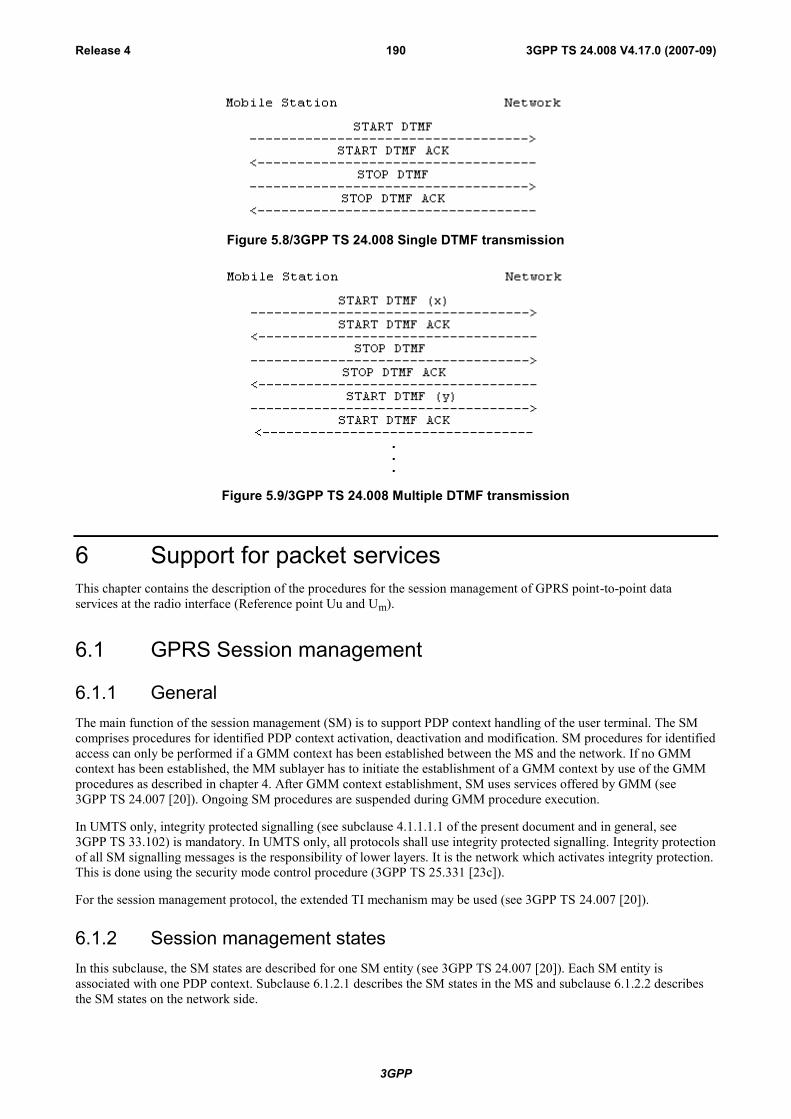
3GPP
3GPP TS 24.008 V4.17.0 (2007-09)Release 4 190
Figure 5.8/3GPP TS 24.008 Single DTMF transmission
Figure 5.9/3GPP TS 24.008 Multiple DTMF transmission
6 Support for packet servicesThis chapter contains the description of the procedures for the session management of GPRS point-to-point dataservices at the radio interface (Reference point Uu and Um).
6.1 GPRS Session management
6.1.1 GeneralThe main function of the session management (SM) is to support PDP context handling of the user terminal. The SMcomprises procedures for identified PDP context activation, deactivation and modification. SM procedures for identifiedaccess can only be performed if a GMM context has been established between the MS and the network. If no GMMcontext has been established, the MM sublayer has to initiate the establishment of a GMM context by use of the GMMprocedures as described in chapter 4. After GMM context establishment, SM uses services offered by GMM (see3GPP TS 24.007 [20]). Ongoing SM procedures are suspended during GMM procedure execution.
In UMTS only, integrity protected signalling (see subclause 4.1.1.1.1 of the present document and in general, see3GPP TS 33.102) is mandatory. In UMTS only, all protocols shall use integrity protected signalling. Integrity protectionof all SM signalling messages is the responsibility of lower layers. It is the network which activates integrity protection.This is done using the security mode control procedure (3GPP TS 25.331 [23c]).
For the session management protocol, the extended TI mechanism may be used (see 3GPP TS 24.007 [20]).
6.1.2 Session management statesIn this subclause, the SM states are described for one SM entity (see 3GPP TS 24.007 [20]). Each SM entity isassociated with one PDP context. Subclause 6.1.2.1 describes the SM states in the MS and subclause 6.1.2.2 describesthe SM states on the network side.
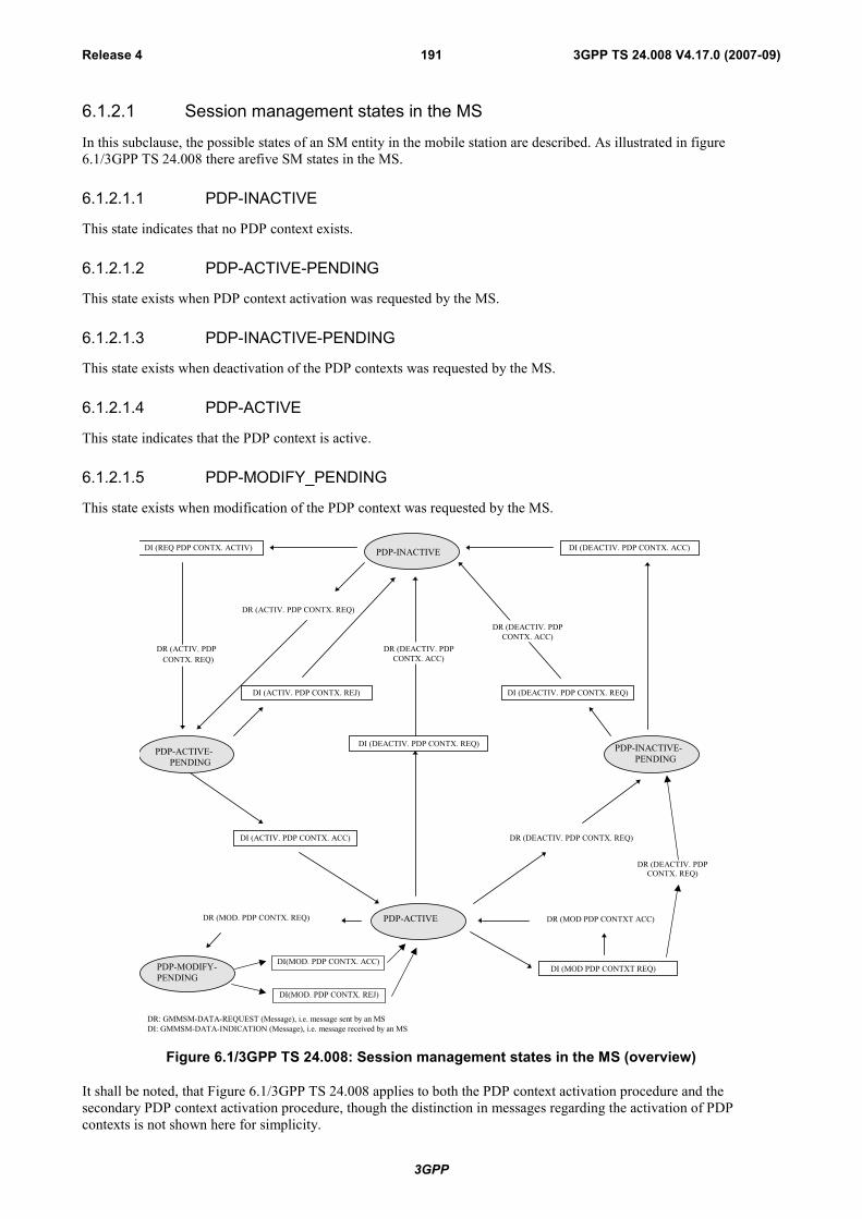
3GPP
3GPP TS 24.008 V4.17.0 (2007-09)Release 4 191
6.1.2.1 Session management states in the MS
In this subclause, the possible states of an SM entity in the mobile station are described. As illustrated in figure6.1/3GPP TS 24.008 there arefive SM states in the MS.
6.1.2.1.1 PDP-INACTIVE
This state indicates that no PDP context exists.
6.1.2.1.2 PDP-ACTIVE-PENDING
This state exists when PDP context activation was requested by the MS.
6.1.2.1.3 PDP-INACTIVE-PENDING
This state exists when deactivation of the PDP contexts was requested by the MS.
6.1.2.1.4 PDP-ACTIVE
This state indicates that the PDP context is active.
6.1.2.1.5 PDP-MODIFY_PENDING
This state exists when modification of the PDP context was requested by the MS.
PDP-ACTIVE-PENDING
PDP-ACTIVE
PDP-INACTIVE
PDP-INACTIVE-PENDING
DR (ACTIV. PDP CONTX. REQ)
DI (ACTIV. PDP CONTX. REJ) DI (DEACTIV. PDP CONTX. REQ)
DR: GMMSM-DATA-REQUEST (Message), i.e. message sent by an MSDI: GMMSM-DATA-INDICATION (Message), i.e. message received by an MS
DI (DEACTIV. PDP CONTX. REQ)
DR (DEACTIV. PDPCONTX. ACC)
DI (DEACTIV. PDP CONTX. ACC)
DR (DEACTIV. PDPCONTX. ACC)
DR (MOD PDP CONTXT ACC)
DI (ACTIV. PDP CONTX. ACC) DR (DEACTIV. PDP CONTX. REQ)
DI (MOD PDP CONTXT REQ)PDP-MODIFY-PENDING
DR (MOD. PDP CONTX. REQ)
DI (REQ PDP CONTX. ACTIV)
DR (ACTIV. PDP CONTX. REQ)
DR (DEACTIV. PDPCONTX. REQ)
DI(MOD. PDP CONTX. REJ)
DI(MOD. PDP CONTX. ACC)
Figure 6.1/3GPP TS 24.008: Session management states in the MS (overview)
It shall be noted, that Figure 6.1/3GPP TS 24.008 applies to both the PDP context activation procedure and thesecondary PDP context activation procedure, though the distinction in messages regarding the activation of PDPcontexts is not shown here for simplicity.

3GPP
3GPP TS 24.008 V4.17.0 (2007-09)Release 4 192
6.1.2.2 Session management states on the network side
In this subclause, the possible states of an SM entity on the network side are described. As illustrated in figure 6.2/3GPPTS 24.008 there are five SM states on the network side.
6.1.2.2.1 PDP-INACTIVE
This state indicates that the PDP context is not active.
6.1.2.2.2 PDP-ACTIVE-PENDING
This state exists when the PDP context activation was initiated by the network.
6.1.2.2.3 PDP-INACTIVE-PENDING
This state exists when deactivation of the PDP context was requested by the network.
6.1.2.2.4 PDP-ACTIVE
This state indicates that the PDP context is active.
6.1.2.2.5 PDP-MODIFY-PENDING
This state exists when modification of the PDP context was requested by the network.
DR: GMMSM-DATA-REQUEST (Message), i.e. message sent by networkDI: GMMSM-DATA-INDICATION (Message), i.e. message received by the network
PDP-INACTIVE-PEND
DR (DEACTIV. PDP CONTX. REQ) DI (DEACTIV. PDP CONTX. ACC)
DI (DEACTIV. PDP CONTX. REQ)
DR (DEACTIV. PDP CONTX. ACC)
DI (ACTIV. PDP CONTX. REQ)DR (ACTIV. PDP CONTX. ACC)
PDP ACTIVE
PDP-MODIFY-PEND
DR (MODIFY. PDP CONTX. REQ)
DI (MODIFY. PDP CONTX. ACC)
PDP-ACTIVE-PEND
DR (REQ PDP CONTX. ACTIV)
PDP-INACTIVE
DI (ACTIV. PDP CONTX. REQ)
DR (ACTIV. PDP CONTX. ACC)
DR (ACTIV. PDP CONTX. REJ)
DR (MOD PDPCONTXT REJ)
DI (MOD PDP CONTXT REQ)
DI (DEACTIV. PDP CONTX. REQ)
DR (DEACTIV. PDP CONTX. ACC)
DI (REQ PDP CONTX. ACTIV. REJ)DR (MOD PDPCONTXT ACC)
Figure 6.2/3GPP TS 24.008: Session management states on the network side (overview)

3GPP
3GPP TS 24.008 V4.17.0 (2007-09)Release 4 193
It shall be noted, that figure 6.2/3GPP TS 24.008 applies to both the PDP context activation procedure and thesecondary PDP context activation procedure, though the distinction in messages regarding the activation of PDPcontexts is not shown here for simplicity.
6.1.3 Session Management procedures
6.1.3.1 PDP context activation
The purpose of this procedure is to establish a PDP context between the MS and the network for a specific QoS on aspecific NSAPI. The PDP context activation may be initiated by the MS or the initiation may be requested by thenetwork.
Each PDP address may be described by one or more PDP contexts in the MS or the network. The PDP ContextActivation procedure is used to activate the first PDP context for a given PDP address and APN, whereas all additionalcontexts associated to the same PDP address and APN are activated with the secondary PDP context activationprocedure. When more than one PDP contexts are associated to a PDP address, there shall be a Traffic Flow Template(TFT) for each or all but one context. If present, the TFT shall be sent transparently via the SGSN to the GGSN toenable packet classification and policing for downlink data transfer (see 3GPP TS 23.060 [74]).
6.1.3.1.1 Successful PDP context activation initiated by the mobile station
In order to request a PDP context activation, the MS sends an ACTIVATE PDP CONTEXT REQUEST message to thenetwork, enters the state PDP-ACTIVE-PENDING and starts timer T3380. The message contains the selected NSAPI,PDP type, requested QoS and, if the MS requests a static address, the PDP address. The MS shall ensure that theselected NSAPI is not currently being used by another Session Management entity in the MS.
Upon receipt of an ACTIVATE PDP CONTEXT REQUEST message, the network selects a radio priority level basedon the QoS negotiated and may reply with an ACTIVATE PDP CONTEXT ACCEPT message. Upon receipt of themessage ACTIVATE PDP CONTEXT ACCEPT the MS shall stop timer T3380, shall enter the state PDP-ACTIVE. Ifthe offered QoS parameters received from the network differ from the QoS requested by the MS, the MS shall eitheraccept the negotiated QoS or initiate the PDP context deactivation procedure.
In GSM, the MS shall initiate establishment of the logical link for the LLC SAPI indicated by the network with theoffered QoS and selected radio priority level if no logical link has been already established for that SAPI. If the offeredQoS parameters received from the network differ from the QoS requested by the MS, the MS shall either accept thenegotiated QoS or initiate the PDP context deactivation procedure. If the LLC SAPI indicated by the network can not besupported by the MS, the MS shall initiate the PDP context deactivation procedure.
In UMTS, both the network and the MS shall store the LLC SAPI and the radio priority in the PDP context. If a UMTSto GSM system change is performed, the new SGSN shall initiate establishment of the logical link using the negotiatedQoS profile, the negotiated LLC SAPI, and selected radio priority level stored in the PDP context as in a GSM to GSMRouting Area Update.
An MS, which is capable of operating in both GSM and UMTS, shall use a valid LLC SAPI, while an MS which iscapable of operating only in UMTS shall indicate the LLC SAPI value as "LLC SAPI not assigned" in order to avoidunnecessary value range checking and any other possible confusion in the network. When the MS uses a valid LLCSAPI, the network shall return a valid LLC SAPI. The network shall return the “LLC SAPI not assigned” value onlywhen the MS uses the “LLC SAPI not assigned” value.
NOTE: The radio priority level and the LLC SAPI parameters, though not used in UMTS, shall be included in themessages, in order to support handover between UMTS and GSM networks.
6.1.3.1.2 Successful PDP context activation requested by the network
In order to request a PDP context activation, the network sends a REQUEST PDP CONTEXT ACTIVATION messageto the MS and starts timer T3385. The message contains an offered PDP address. If available, the APN shall be includedin the REQUEST PDP CONTEXT ACTIVATION message.
Upon receipt of a REQUEST PDP CONTEXT ACTIVATION message, the MS shall than either initiate the PDPcontext activation procedure as described in the previous subclause or shall reject the activation request by sending aREQUEST PDP CONTEXT ACTIVATION REJECT message as described in subclause 6.1.3.1.4. The value of the
3GPP
3GPP TS 24.008 V4.17.0 (2007-09)Release 4 194
reject cause IE of the REQUEST PDP CONTEXT ACTIVATION REJECT message shall indicate the reason forrejection, e.g. "insufficient resources to activate another context".
The ACTIVATE PDP CONTEXT REQUEST message sent by the MS in order to initiate the PDP context activationprocedure shall contain the PDP address, PDP Type and APN requested by the network in the REQUEST PDPCONTEXT ACTIVATION message.
Upon receipt of the ACTIVATE PDP CONTEXT REQUEST message, the network shall stop timer T3385.
The same procedures then apply as described for MS initiated PDP context activation.
6.1.3.1.3 Unsuccessful PDP context activation initiated by the MS
Upon receipt of an ACTIVATE PDP CONTEXT REQUEST message the network may reject the MS initiated PDPcontext activation by sending an ACTIVATE PDP CONTEXT REJECT message to the MS. The message shall containa cause code that typically indicates one of the following causes:
# 8: Operator Determined Barring;
# 26: insufficient resources;
# 27: missing or unknown APN;
# 28: unknown PDP address or PDP type;
# 29: user authentication failed;
# 30: activation rejected by GGSN;
# 31: activation rejected, unspecified;
# 32: service option not supported;
# 33: requested service option not subscribed;
# 34: service option temporarily out of order;
# 35: NSAPI already used. The network shall not send this cause code (see note 1); or
# 95 - 111: protocol errors.
NOTE 1: Pre-R99 network may send this cause code.
Upon receipt of an ACTIVATE PDP CONTEXT REJECT message, the MS shall stop timer T3380 and enter/remain instate PDP-INACTIVE.
6.1.3.1.4 Unsuccessful PDP context activation requested by the network
Upon receipt of the REQUEST PDP CONTEXT ACTIVATION message, the MS may reject the network requestedPDP context activation by sending the REQUEST PDP CONTEXT ACTIVATION REJECT message to the network.The message contains the same TI as included in the REQUEST PDP CONTEXT ACTIVATION and an additionalcause code that typically indicates one of the following causes:
# 26: insufficient resources;
# 31: activation rejected, unspecified;
# 40: feature not supported; or
# 95 - 111: protocol errors.
The network shall stop timer T3385 and enter state PDP-INACTIVE.
6.1.3.1.5 Abnormal cases
The following abnormal cases can be identified:

3GPP
3GPP TS 24.008 V4.17.0 (2007-09)Release 4 195
a) Expiry of timers
In the mobile station:
On the first expiry of the timer T3380, the MS shall resend the ACTIVATE PDP CONTEXT REQUEST andshall reset and restart timer T3380. This retransmission is repeated four times, i.e. on the fifth expiry of timerT3380, the MS shall release all resources possibly allocated for this invocation and shall abort the procedure;no automatic PDP context activation re-attempt shall be performed.
On the network side:
On the first expiry of the timer T3385, the network shall resend the message REQUEST PDP CONTEXTACTIVATION and shall reset and restart timer T3385. This retransmission is repeated four times, i.e. on thefifth expiry of timer T3385, the network shall release possibly allocated resources for this activation and shallabort the procedure.
b) Collision of MS initiated and network requested PDP context activation
Dynamic PDP address collision case:
If the MS uses dynamic PDP addressing that turns out to collide with the network requested PDP address, thenthere is no detection of collision specified but left for network implementation.
Static PDP address collision detected within the mobile station:
A collision of an MS initiated and a network requested PDP context activation procedure is identified by theMS if a REQUEST PDP CONTEXT ACTIVATION message is received from the network after the MS hassent an ACTIVATE PDP CONTEXT REQUEST message, and the MS has not yet received an ACTIVATEPDP CONTEXT ACCEPT or ACTIVATE PDP CONTEXT REJECT message.
NOTE: In general, the MS is unable to test if the PDP type, PDP address and APN in the REQUEST PDPCONTEXT ACTIVATION message are the same as those for the PDN to which it is attempting toactivate a context. This is because the MS may have omitted one or more of the parameters in theACTIVATE PDP CONTEXT REQUEST message, since it is relying on default values to be provided bythe network.
- In the case of such a collision, the MS initiated PDP context activation shall take precedence over thenetwork requested PDP context activation. If the MS is able to compare the PDP type, PDP address and APNrequested in the ACTIVATE PDP CONTEXT REQUEST message with those requested in the REQUESTPDP CONTEXT ACTIVATION message and these parameters are equal, then the MS shall discard theREQUEST PDP CONTEXT ACTIVATION message and shall wait for the network response to itsACTIVATE PDP CONTEXT REQUEST message. If the MS is not able to compare the PDP type, PDPaddress, and APN requested in the ACTIVATE PDP CONTEXT REQUEST message with those requested inthe REQUEST PDP CONTEXT ACTIVATION message, then the MS shall send a REQUEST PDPCONTEXT ACTIVATION REJECT message with the cause 'insufficient resources' to the network, and waitfor an ACTIVATE PDP CONTEXT ACCEPT message.
Static PDP address collision detected on the network side:
A collision is detected by the network in the case where the PDP address, PDP type and APN derived(according to 23.060 annex A) from the ACTIVATE PDP CONTEXT REQUEST message received from theMS match those in the REQUEST PDP CONTEXT ACTIVATION message sent to the MS.
- In the case of such a collision, the MS initiated PDP context activation shall take precedence over thenetwork requested PDP context activation. The network shall terminate the network requested PDP contextactivation procedure, and proceed with the MS initiated PDP context activation procedure.
c) MS initiated PDP context activation request for an already activated PDP context (on the network side)
i) If the network receives a ACTIVATE PDP CONTEXT REQUEST message with the same combinationof APN, PDP type and PDP address as an already activated PDP context, the network shall deactivate theexisting PDP context and, if any, all the linked PDP contexts (matching the combination of APN, PDPtype and PDP address), locally without notification to the MS and proceed with the requested PDPcontext activation.
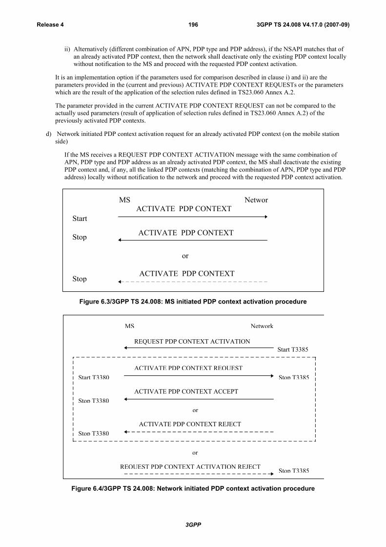
3GPP
3GPP TS 24.008 V4.17.0 (2007-09)Release 4 196
ii) Alternatively (different combination of APN, PDP type and PDP address), if the NSAPI matches that ofan already activated PDP context, then the network shall deactivate only the existing PDP context locallywithout notification to the MS and proceed with the requested PDP context activation.
It is an implementation option if the parameters used for comparison described in clause i) and ii) are theparameters provided in the (current and previous) ACTIVATE PDP CONTEXT REQUESTs or the parameterswhich are the result of the application of the selection rules defined in TS23.060 Annex A.2.
The parameter provided in the current ACTIVATE PDP CONTEXT REQUEST can not be compared to theactually used parameters (result of application of selection rules defined in TS23.060 Annex A.2) of thepreviously activated PDP contexts.
d) Network initiated PDP context activation request for an already activated PDP context (on the mobile stationside)
If the MS receives a REQUEST PDP CONTEXT ACTIVATION message with the same combination ofAPN, PDP type and PDP address as an already activated PDP context, the MS shall deactivate the existingPDP context and, if any, all the linked PDP contexts (matching the combination of APN, PDP type and PDPaddress) locally without notification to the network and proceed with the requested PDP context activation.
MS NetworkACTIVATE PDP CONTEXT
REQUESTStartT3380
ACTIVATE PDP CONTEXTACCEPT
ACTIVATE PDP CONTEXTREJECTStop
T3380
StopT3380
or
Figure 6.3/3GPP TS 24.008: MS initiated PDP context activation procedure
MS Network
REQUEST PDP CONTEXT ACTIVATIONStart T3385
Start T3380
ACTIVATE PDP CONTEXT ACCEPTStop T3380
ACTIVATE PDP CONTEXT REQUEST
Stop T3380ACTIVATE PDP CONTEXT REJECT
Stop T3385
or
or
REQUEST PDP CONTEXT ACTIVATION REJECTECREJECT Stop T3385
Figure 6.4/3GPP TS 24.008: Network initiated PDP context activation procedure
3GPP
3GPP TS 24.008 V4.17.0 (2007-09)Release 4 197
6.1.3.2 Secondary PDP Context Activation Procedure
The purpose of this procedure is to establish an additional PDP context between the MS and the network for a specificTraffic Flow Template (TFT) and QoS profile on a specific NSAPI, when one or more PDP contexts has/have alreadybeen established for the particular PDP address. The MS shall include a request for a TFT if a PDP context without aTFT is presently active, for the particular PDP address.
6.1.3.2.1 Successful Secondary PDP Context Activation Procedure Initiated by the MS
In order to request a PDP context activation with the same PDP address and APN as an already active PDP context, theMS shall send an ACTIVATE SECONDARY PDP CONTEXT REQUEST message to the network, enter the statePDP-ACTIVE-PENDING and start timer T3380. The message shall contain the selected NSAPI. The MS shall ensurethat the selected NSAPI is not currently being used by another Session Management entity in the MS. The messageshall also include a QoS profile, a requested LLC SAPI and the Linked TI. The QoS profile is the requested QoS. Ifpresent, the TFT shall be sent transparently through the SGSN to the GGSN to enable packet classification andpolicing for downlink data transfer.
Upon receipt of an ACTIVATE SECONDARY PDP CONTEXT REQUEST, the network shall validate the message byverifying the TI given in the Linked TI IE to be any of the active PDP context(s). The same GGSN address shall beused by the SGSN as for the already established PDP context(s) for that PDP address. The network shall select a radiopriority level based on the QoS negotiated and shall reply with an ACTIVATE SECONDARY PDP CONTEXTACCEPT message, if the request can be accepted.
Upon receipt of the message ACTIVATE SECONDARY PDP CONTEXT ACCEPT, the MS shall stop timer T3380and enter the state PDP-ACTIVE. If the offered QoS parameters received from the network differ from the QoSrequested by the MS, the MS shall either accept the negotiated QoS or initiate the PDP context deactivation procedure.
In GSM the MS shall initiate establishment of the logical link for the LLC SAPI indicated by the network with theoffered QoS and selected radio priority level if no logical link has been already established for that SAPI. If the LLCSAPI indicated by the network can not be supported by the MS, the MS shall initiate the PDP context deactivationprocedure.
In UMTS, both SGSN and MS shall store the LLC SAPI and the radio priority in the PDP context. If a UMTS to GSMRouting Area Update is performed, the new SGSN shall initiate establishment of the logical link using the negotiatedLLC SAPI, the negotiated QoS profile and selected radio priority level stored in the PDP context as in a GSM to GSMRouting Area Update.
An MS, which is capable of operating in both GSM and UMTS, shall use a valid LLC SAPI, while an MS which iscapable of operating only in UMTS shall indicate the LLC SAPI value as "LLC SAPI not assigned" in order to avoidunnecessary value range checking and any other possible confusion in the network. When the MS uses a valid LLCSAPI, the network shall return a valid LLC SAPI. The network shall return the “LLC SAPI not assigned” value onlywhen the MS uses the “LLC SAPI not assigned” value.
NOTE: The radio priority level and the LLC SAPI parameters, though not used in UMTS, shall be included in themessages, in order to support handover between UMTS and GSM networks.
3GPP
3GPP TS 24.008 V4.17.0 (2007-09)Release 4 198
6.1.3.2.2 Unsuccessful Secondary PDP Context Activation Procedure initiated by the MS
Upon receipt of an ACTIVATE SECONDARY PDP CONTEXT REQUEST message, the network may reject the MSinitiated PDP context activation by sending an ACTIVATE SECONDARY PDP CONTEXT REJECT message to theMS. The message shall contain a cause code that typically indicates one of the following:
# 26: insufficient resources;
# 30: activation rejected by GGSN;
# 31: activation rejected, unspecified;
# 32: service option not supported;
# 33: requested service option not subscribed;
# 34: service option temporarily out of order;
# 41: semantic error in the TFT operation;
# 42: syntactical error in the TFT operation;
# 43: unknown PDP context;
# 44: semantic errors in packet filter(s);
# 45: syntactical errors in packet filter(s);
# 46: PDP context without TFT already activated;
# 95: 111: protocol errors.
Upon receipt of an ACTIVATE SECONDARY PDP CONTEXT REJECT message, the MS shall stop timer T3380 andenter the state PDP-INACTIVE.
6.1.3.2.3 Abnormal cases
The following abnormal cases can be identified:
a) Expiry of timers
On the first expiry of the timer T3380, the MS shall resent the ACTIVATE SECONDARY PDP CONTEXTREQUEST and shall reset and restart timer T3380. This retransmission is repeated four times, i.e. on the fifthexpiry of timer T3380, the MS shall release all resources possibly allocated for this invocation and shall abort theprocedure; no automatic PDP context activation re-attempt shall be performed.
b) MS initiated secondary PDP context activation procedure for an already activated PDP context (On the networkside)
If the NSAPI matches that of an already activated PDP context, the network shall deactivate the existing PDPcontext locally without notification to the MS and proceed with the requested PDP context activation.
Otherwise, the network shall check the parameters as follows:
The network shall first check whether there is an activated PDP context for the TI given in the Linked TI IE in theACTIVATE SECONDARY PDP CONTEXT REQUEST message. If there is no active PDP context for the specifiedTI, the network shall reply with an ACTIVATE SECONDARY PDP CONTEXT REJECT message, cause codeindicating "unknown PDP context". If there exists a PDP context for the TI given in the Linked TI IE, then the TFT inthe request message is checked for different types of TFT IE errors as follows:
a) Semantic errors in TFT operations:
1) When the TFT operation is an operation other than "Create a new TFT".
The network shall reject the activation request with cause "semantic error in the TFT operation".

3GPP
3GPP TS 24.008 V4.17.0 (2007-09)Release 4 199
b) Syntactical errors in TFT operations:
1) When the TFT operation = "Create a new TFT" and the packet filter list in the TFT IE is empty.
2) When there are other types of syntactical errors in the coding of the TFT IE, such as a mismatch between thenumber of packet filters subfield, and the number of packet filters in the packet filter list.
The network shall reject the activation request with cause "syntactical error in the TFT operation".
c) Semantic errors in packet filters:
1) When a packet filter consists of conflicting packet filter components which would render the packet filterineffective, i.e., no IP packet will ever fit this packet filter. How the network determines a semantic error in apacket filter is outside the scope of the present document.
The network shall reject the activation request with cause "semantic errors in packet filter(s)".
d) Syntactical errors in packet filters:
1) When the TFT operation = "Create a new TFT" and two or more packet filters in the resultant TFT wouldhave identical packet filter identifiers.
2) When the TFT operation = "Create a new TFT" and two or more packet filters in all TFTs associated withthis PDP address would have identical packet filter precedence values.
3) When there are other types of syntactical errors in the coding of packet filters, such as the use of a reservedvalue for a packet filter component identifier.
The network shall reject the activation request with cause "syntactical errors in packet filter(s)".
Otherwise, the network shall accept the activation request by replying to the MS with an ACTIVATE SECONDARYPDP CONTEXT ACCEPT message.
MS Network
ACTIVATE SECONDARY PDP CONTEXT REQUESTStart T3380
ACTIVATE SECONDARY PDP CONTEXT ACCEPT
ACTIVATE SECONDARY PDP CONTEXT REJECTStop T3380
Stop T3380
or
Figure 6.5/3GPP TS 24.008: MS initiated secondary PDP context activation procedure
6.1.3.3 PDP context modification procedure
The PDP context modification procedure is invoked by the network or by the MS, in order to change the QoSnegotiated, the Radio priority level, or the TFT, negotiated during the PDP context activation procedure, the secondaryPDP context activation procedure or at previously performed PDP context modification procedures. The MS may alsocreate and delete a TFT in an active PDP context. The procedure can be initiated by the network or the MS at any timewhen a PDP context is active.
The PDP context modification procedure may also be invoked by the MS, in order to upgrade the maximum bit rate andto trigger the re-establishment of the radio access bearer for an activated PDP context which is preserved in the MSwith maximum bit rate values of 0kbit/s for both uplink and downlink (see 3GPP TS 23.060 [74]). If
- the PDP Context Modification request is accepted by the network but the radio access bearer is not established;or
- the PDP Context Modification request is rejected with cause "insufficient resources" (see subclause 6.1.3.3.3),

3GPP
3GPP TS 24.008 V4.17.0 (2007-09)Release 4 200
then the MS is not required to start a new PDP Context Modification procedure or to start a Service Request procedurein order to trigger the re-establishment of the radio access bearer.
The network requested PDP context modification procedure may also be used to update the PDP address when externalPDN address allocation is performed, in which case the MS receives the PDP address in the MODIFY PDP CONTEXTREQUEST (Network to MS direction) message.
NOTE: The procedure may be initiated by the network due to an inter-SGSN Routing Area Updating when a PDPcontext is active.
6.1.3.3.1 Network initiated PDP Context Modification
In order to initiate the procedure, the network sends the MODIFY PDP CONTEXT REQUEST message to the MS andstarts timer T3386. The message shall contain the new QoS and the radio priority level and LLC SAPI that shall be usedby the MS in GSM at the lower layers for the transmission of data related to the PDP context.
Upon receipt of this message the MS shall reply with the MODIFY PDP CONTEXT ACCEPT message, if the MSaccepts the new QoS and the indicated LLC SAPI.
If the MS does not accept the new QoS or the indicated LLC SAPI, the MS shall initiate the PDP context deactivationprocedure for the PDP context - the reject cause IE value of the DEACTIVATE PDP CONTEXT REQUEST messageshall indicate "QoS not accepted".
The network shall upon receipt of the MODIFY PDP CONTEXT ACCEPT message stop timer T3386.
In GSM, the network shall establish, reconfigure or continue using the logical link with the new QoS for the LLC SAPIindicated in the MODIFY PDP CONTEXT REQUEST message.
In UMTS, the network shall establish, reconfigure or continue using the Radio Access Bearer with the new QoSindicated in the MODIFY PDP CONTEXT REQUEST message.
6.1.3.3.2 MS initiated PDP Context Modification accepted by the network
In order to initiate the procedure, the MS sends the MODIFY PDP CONTEXT REQUEST message to the network,enters the state PDP-MODIFY-PENDING and starts timer T3381. The message may contain the requested new QoSand/or the TFT and the requested LLC SAPI (used in GSM).
Upon receipt of the MODIFY PDP CONTEXT REQUEST message, the network may reply with the MODIFY PDPCONTEXT ACCEPT message in order to accept the context modification. The reply message may contain thenegotiated QoS and the radio priority level based on the new QoS profile and the negotiated LLC SAPI, that shall beused in GSM by the logical link.
Upon receipt of the MODIFY PDP CONTEXT ACCEPT message, the MS shall stop the timer T3381. If the offeredQoS parameters received from the network differs from the QoS requested by the MS, the MS shall either accept thenegotiated QoS or initiate the PDP context deactivation procedure.
NOTE: When modification of QoS was requested by the MS, if the network does not accept the MS request,being unable to provide the requested QoS, it should maintain the QoS negotiated as previouslynegotiated or propose a new QoS. Therefore, the network would not reject the MS initiated PDP contextmodification request due to the unavailability of the required QoS.

3GPP
3GPP TS 24.008 V4.17.0 (2007-09)Release 4 201
6.1.3.3.3 MS initiated PDP Context Modification not accepted by the network
Upon receipt of a MODIFY PDP CONTEXT REQUEST message, the network may reject the MS initiated PDPcontext modification request by sending a MODIFY PDP CONTEXT REJECT message to the MS. The message shallcontain a cause code that typically indicates one of the following:
# 26: insufficient resources;
# 32: Service option not supported;
# 41: semantic error in the TFT operation;
# 42: syntactical error in the TFT operation;
# 44: semantic errors in packet filter(s);
# 45: syntactical errors in packet filter(s);
# 95 - 111: protocol errors.
If upon the reception of a MODIFY PDP CONTEXT REQUEST message the network fails to re-establish the radioaccess bearer for a PDP context whose maximum bit rate in uplink and downlink is set to 0kbit/s, the network shallreply with MODIFY PDP CONTEXT REJECT with cause "insufficient resources".
The TFT in the request message is checked for different types of TFT IE errors as follows:
a) Semantic errors in TFT operations:
I. TFT operation = "Create a new TFT" when there is already an existing TFT for the PDP context.
II. When the TFT operation is an operation other than "Create a new TFT" and there is no TFT for the PDPcontext.
III. TFT operation = "Delete existing TFT" when there is already another PDP context without a TFT.
IV. TFT operation = "Delete packet filters from existing TFT" when it would render the TFT empty.
The network shall reject the activation request with cause "semantic error in the TFT operation".
b) Syntactical errors in TFT operations:
I. When the TFT operation is an operation other than "Delete existing TFT" and the packet filter list in the TFT IEis empty.
II. TFT operation = "Delete existing TFT" with a non-empty packet filter list in the TFT IE.
III. TFT operation = "Replace packet filters in existing TFT" when a to be replaced packet filter does not exist in theoriginal TFT.
IV.TFT operation = "Delete packet filters from existing TFT" when a to be deleted packet filter does not exist in theoriginal TFT.
V. TFT operation = "Delete packet filters from existing TFT" with a packet filter list including packet filters insteadof packet filter identifiers.
VI.When there are other types of syntactical errors in the coding of the TFT IE, such as a mismatch between thenumber of packet filters subfield, and the number of packet filters in the packet filter list.
The network shall reject the activation request with cause "syntactical error in the TFT operation".
c) Semantic errors in packet filters:
When a packet filter consists of conflicting packet filter components which would render the packet filterineffective, i.e., no IP packet will ever fit this packet filter. How the network determines a semantic error in apacket filter is outside the scope of the present document.
The network shall reject the activation request with cause "semantic errors in packet filter(s)".

3GPP
3GPP TS 24.008 V4.17.0 (2007-09)Release 4 202
d) Syntactical errors in packet filters:
I. When the TFT operation = "Create a new TFT" or "Add packet filters to existing TFT" and two or morepacket filters in the resultant TFT would have identical packet filter identifiers.
II. When the TFT operation = "Create a new TFT" or "Add packet filters to existing TFT" or "Replace packetfilters in existing TFT" and two or more packet filters in all TFTs associated with this PDP address wouldhave identical packet filter precedence values.
III. When there are other types of syntactical errors in the coding of packet filters, such as the use of a reservedvalue for a packet filter component identifier.
The network shall reject the activation request with cause "syntactical errors in packet filter(s)".
Upon receipt of a MODIFY PDP CONTEXT REJECT message, the MS shall stop timer T3381 and enter the statePDP-ACTIVE.
6.1.3.3.4 Abnormal cases
a) Expiry of timers
On the network side:
On the first expiry of timer T3386, the network shall resend the MODIFY PDP CONTEXT REQUESTmessage reset and restart timer T3386. This retransmission is repeated four times, i.e. on the fifth expiry oftimer T3386, the network may continue to use the previously negotiated QoS or it may initiate the PDPcontext deactivation procedure.
In the MS:
On the first expiry of timer T3381, the MS shall resend the MODIFY PDP CONTEXT REQUEST messagereset and restart timer T3381. This retransmission is repeated four times, i.e. on the fifth expiry of timerT3381, the MS may continue to use the previously negotiated QoS or it may initiate the PDP contextdeactivation procedure.
b) Collision of MS and Network initiated PDP Context Modification Procedures
A collision of a MS and network initiated PDP context modification procedures is identified by the MS if aMODIFY PDP CONTEXT REQUEST message is received from the network after the MS has sent a MODIFYPDP CONTEXT REQUEST message itself, and both messages contain the same TI and the MS has not yetreceived a MODIFY PDP CONTEXT ACCEPT message from the network.
A collision is detected by the network in case a MODIFY PDP CONTEXT REQUEST message is received fromthe MS with the same TI as the MODIFY PDP CONTEXT REQUEST message sent to the MS.
In the case of such a collision, the network initiated PDP context modification shall take precedence over the MSinitiated PDP context modification. The MS shall terminate internally the MS initiated PDP context modificationprocedure, enter the state PDP-Active and proceed with the network initiated PDP context modificationprocedure by sending a MODIFY PDP CONTEXT ACCEPT message. The network shall ignore the MODIFYPDP CONTEXT REQUEST message received in the state PDP-MODIFY-PENDING. The network shallproceed with the network initiated PDP context modification procedure as if no MODIFY PDP CONTEXTREQUEST message was received from the MS.
MS NetworkMODIFY PDP CONTEXT REQUEST
Start T3386
MODIFY PDP CONTEXT ACCEPTStop T3386
Figure 6.6/3GPP TS 24.008: Network initiated PDP context modification procedure

3GPP
3GPP TS 24.008 V4.17.0 (2007-09)Release 4 203
MS Network
MODIFY PDP CONTEXTREQUESTStart T3381
MODIFY PDP CONTEXTACCEPTStop T3381
MODIFY PDP CONTEXTREJEXTStop T3381
or
Figure 6.7/3GPP TS 24.008: MS initiated PDP context modification procedure
6.1.3.4 PDP context deactivation procedure
The purpose of this procedure is to deactivate an existing PDP context between the MS and the network. The PDPcontext deactivation may be initiated by the MS or by the network. The tear down indicator information element maybe included in the DEACTIVATE PDP CONTEXT REQUEST message in order to indicate whether only the PDPcontext associated with this specific TI or all active PDP contexts sharing the same PDP address as the PDP contextassociated with this specific TI shall be deactivated. If the tear down indicator information element is not included inthe DEACTIVATE PDP CONTEXT REQUEST message, only the PDP context associated with this specific TI shall bedeactivated.
After successful PDP context deactivation, the associated NSAPI and TI values are released and can be reassigned toanother PDP context.
6.1.3.4.1 PDP context deactivation initiated by the MS
In order to deactivate a PDP context, the MS sends a DEACTIVATE PDP CONTEXT REQUEST message to thenetwork, enters the state PDP-INACTIVE-PENDING and starts timer T3390. The message contains the transactionidentifier (TI) in use for the PDP context to be deactivated and a cause code that typically indicates one of the followingcauses:
# 25: LLC or SNDCP failure(GSM only);
# 26: insufficient resources;
# 36: regular PDP context deactivation; or
# 37: QoS not accepted.
The network shall reply with the DEACTIVATE PDP CONTEXT ACCEPT message. Upon receipt of theDEACTIVATE PDP CONTEXT ACCEPT message, the MS shall stop timer T3390. In GSM, both the MS and thenetwork shall initiate local release of the logical link if it is not used by another PDP context. In UMTS, the networkshall initiate the release of Radio Access Bearer associated with this PDP context.
6.1.3.4.2 PDP context deactivation initiated by the network
In order to deactivate a PDP context, the network sends a DEACTIVATE PDP CONTEXT REQUEST message to theMS and starts timer T3395. The message contains the transaction identifier in use for the PDP context to be deactivatedand a cause code that typically indicates one of the following causes:
# 8: Operator Determined Barring;
# 25: LLC or SNDCP failure (GSM only);
# 36: regular PDP context deactivation;
# 38: network failure; or

3GPP
3GPP TS 24.008 V4.17.0 (2007-09)Release 4 204
# 39: reactivation requested.
The MS shall, upon receipt of this message, reply with a DEACTIVATE PDP CONTEXT ACCEPT message. Uponreceipt of the DEACTIVATE PDP CONTEXT ACCEPT message, the network shall stop the timer T3395. In GSM,both the MS and the network shall initiate local release of the logical link if it is not used by another PDP context. InUMTS, the network shall initiate the release of Radio Access Bearer associated with this PDP context.
6.1.3.4.3 Abnormal cases
The following abnormal cases can be identified:
a) Expiry of timers
In the mobile station:
On the first expiry of timer T3390, the MS shall resent the message DEACTIVATE PDP CONTEXTREQUEST and shall reset and restart the timer T3390. This retransmission is repeated four times, i.e. on thefifth expiry of timer T3390, the MS shall release all resources allocated and shall erase the PDP contextrelated data.
On the network side:
On the first expiry of timer T3395, the network shall resent the message DEACTIVATE PDP CONTEXTREQUEST and shall reset and restart timer T3395. This retransmission is repeated four times, i.e. on the fifthexpiry of timer T3395, the network shall erase the PDP context related data for that MS.
b) Collision of MS and network initiated PDP context deactivation requests
If the MS and the network initiated PDP context deactivation requests collide, the MS and the network shall eachreply with the messages DEACTIVATE PDP CONTEXT ACCEPT and shall stop timer T3390 and T3395,respectively.
MS Network
DEACTIVATE PDP CONTEXT REQUESTStart T3390
DEACTIVATE PDP CONTEXT ACCEPTStop T3390
Figure 6.8/3GPP TS 24.008: MS initiated PDP context deactivation procedure
MS Network
Start T3395
DEACTIVATE PDP CONTEXT ACCEPTStop T3395
DEACTIVATE PDP CONTEXT REQUEST
Figure 6.9/3GPP TS 24.008: Network initiated PDP context deactivation procedure
3GPP
3GPP TS 24.008 V4.17.0 (2007-09)Release 4 205
6.1.3.4a Void
6.1.3.5 Void
6.1.3.6 Receiving a SM STATUS message by a SM entity
If the SM entity of the MS receives a SM STATUS message no state transition and no specific action shall be taken asseen from the radio interface, i.e. local actions are possible.
The actions to be taken on receiving a SM STATUS message in the network are an implementation dependent option.
7 Examples of structured proceduresSee 3GPP TS 23.108 [9a]
8 Handling of unknown, unforeseen, and erroneousprotocol data
8.1 GeneralThe procedures specified in 3GPP TS 24.008 and call-related supplementary service handling in 3GPP TS 24.010 [21]apply to those messages which pass the checks described in this subclause.
This subclause also specifies procedures for the handling of unknown, unforeseen, and erroneous protocol data by thereceiving entity. These procedures are called "error handling procedures", but in addition to providing recoverymechanisms for error situations they define a compatibility mechanism for future extensions of the protocols.
Error handling concerning the value part of the Facility IE and of the SS Version Indicator IE are not in the scope of thepresent document. It is defined in 3GPP TS 24.010 [21] and the 3GPP TS 24.08x series.
Sub subclauses 8.1 to 8.8 shall be applied in order of precedence.
Most error handling procedures are mandatory for the mobile station.
Detailed error handling procedures in the network are implementation dependent and may vary from PLMN to PLMN.However, when extensions of this protocol are developed, networks will be assumed to have the error handling that isindicated in this subclause as mandatory ("shall") and that is indicated as strongly recommended ("should").Subclauses 8.2, 8.3, 8.4, 8.5 and 8.7.2 do not apply to the error handling in the network applied to the receipt of initiallayer 3 message: If the network diagnoses an error described in one of these subclause s in the initial layer 3 messagereceived from the mobile station, it shall either:
- try to recognize the classmark and then take further implementation dependent actions; or
- release the RR-connection.
Also, the error handling of the network is only considered as mandatory or strongly recommended when certainthresholds for errors are not reached during a dedicated connection.
For definition of semantical and syntactical errors see 3GPP TS 24.007 [20], subclause 11.4.2.
8.2 Message too shortWhen a message is received that is too short to contain a complete message type information element, that messageshall be ignored, cf. 3GPP TS 24.007 [20].
3GPP
3GPP TS 24.008 V4.17.0 (2007-09)Release 4 206
8.3 Unknown or unforeseen transaction identifier
8.3.1 Call ControlThe mobile station and the network shall ignore a Call Control message received with TI EXT bit = 0. Otherwise, if theTI EXT bit =1 or no extension is used, the behaviour described below shall be followed.
The mobile station and network shall reject a SETUP, EMERGENCY SETUP or START CC message received withoctet 1 part of the TI value coded as "111" by sending RELEASE COMPLETE with cause #81 "Invalid transactionidentifier value" The TI value in RELEASE COMPLETE shall be the complete TI value including the extension octetfrom the message that caused the rejection.
Any message other than SETUP, EMERGENCY SETUP or START CC received with octet 1 part of the TI valuecoded as "111" shall be ignored.
For a call control message received with octet 1 part of the TI value not coded as "111", the following procedures shallapply:
a) For a network that does not support the "Network initiated MO call" option and for all mobile stations:
Whenever any call control message except EMERGENCY SETUP, SETUP or RELEASE COMPLETE isreceived specifying a transaction identifier which is not recognized as relating to an active call or to a call inprogress, the receiving entity shall send a RELEASE COMPLETE message with cause #81 "invalid transactionidentifier value" using the received transaction identifier value and remain in the Null state.
For a network that does support the "Network initiated MO call" option $(CCBS)$:
Whenever any call control message except EMERGENCY SETUP, SETUP, START CC or RELEASECOMPLETE is received specifying a transaction identifier which is not recognized as relating to an active call orto a call in progress, the receiving entity shall send a RELEASE COMPLETE message with cause #81 "invalidtransaction identifier value" using the received transaction identifier value and remain in the Null state.
b) When a RELEASE COMPLETE message is received specifying a transaction identifier which is not recognizedas relating to an active call or to a call in progress, the MM connection associated with that transaction identifiershall be released.
c) For a network that does not support the "Network initiated MO call" option and for all mobile stations:
When an EMERGENCY SETUP or, a SETUP message is received specifying a transaction identifier which isnot recognized as relating to an active call or to a call in progress, and with a transaction identifier flagincorrectly set to "1", this message shall be ignored.
For a network that does support the "Network initiated MO call" option $(CCBS)$:
When an EMERGENCY SETUP, a START CC or, a SETUP message is received specifying a transactionidentifier which is not recognised as relating to an active call or to a call in progress, and with a transactionidentifier flag incorrectly set to "1", this message shall be ignored.
d) When a SETUP message is received by the mobile station specifying a transaction identifier which is recognizedas relating to an active call or to a call in progress, this SETUP message shall be ignored.
e) For a network that does not support the "Network initiated MO call" option:
When an EMERGENCY SETUP message or a SETUP message is received by the network specifying atransaction identifier which is recognized as relating to an active call or to a call in progress, this message neednot be treated and the network may perform other actions.
For a network that does support the "Network initiated MO call" option $(CCBS)$:
When an EMERGENCY SETUP message or a START CC message is received by the network specifying atransaction identifier which is recognised as relating to an active call or to a call in progress, this message neednot be treated and the network may perform other actions.
3GPP
3GPP TS 24.008 V4.17.0 (2007-09)Release 4 207
The same applies to a SETUP message unless the transaction has been established by a START_CC messageand the network is in the "recall present" state (N0.6).
8.3.2 Session ManagementThe mobile station and network shall ignore a session management message with TI EXT bit = 0. Otherwise, thefollowing procedures shall apply:
a) Whenever any session management message except ACTIVATE PDP CONTEXT REQUEST, ACTIVATESECONDARY PDP CONTEXT REQUEST, or SM-STATUS is received by the network specifying atransaction identifier which is not recognized as relating to an active context or to a context that is in the processof activation or deactivation, the network shall send a SM-STATUS message with cause #81 "invalid transactionidentifier value" using the received transaction identifier value including the extension octet and remain in thePDP-INACTIVE state.
b) Whenever any session management message except REQUEST PDP CONTEXT ACTIVATION or SM-STATUS is received by the MS specifying a transaction identifier which is not recognized as relating to anactive context or to a context that is in the process of activation or deactivation, the MS shall send a SM-STATUS message with cause #81 "invalid transaction identifier value" using the received transaction identifiervalue including the extension octet and remain in the PDP-INACTIVE state.
c) When REQUEST PDP CONTEXT ACTIVATION message is received with a transaction identifier flag set to"1", this message shall be ignored.
d) When an ACTIVATE PDP CONTEXT REQUEST message is received specifying a transaction identifier whichis not recognized as relating to a context that is in the process of activation, and with a transaction identifier flagset to "1", this message shall be ignored.
e) Whenever an ACTIVATE PDP CONTEXT REQUEST message is received by the network specifying atransaction identifier relating to a PDP context not in state PDP-INACTIVE, the network shall deactivate the oldPDP context relating to the received transaction identifier without notifying the MS. Furthermore, the networkshall continue with the activation procedure of a new PDP context as indicated in the received message.
f) Whenever a REQUEST PDP CONTEXT ACTIVATION message is received by the MS specifying a transactionidentifier relating to a PDP context not in state PDP-INACTIVE, the MS shall locally deactivate the old PDPcontext relating to the received transaction identifier. Furthermore, the MS shall continue with the activationprocedure of a new PDP context as indicated in the received message.
8.4 Unknown or unforeseen message typeIf a mobile station receives an RR, MM or CC message with message type not defined for the PD or not implementedby the receiver in unacknowledged mode, it shall ignore the message.
If a mobile station receives an RR, MM or CC message with message type not defined for the PD or not implementedby the receiver in acknowledged mode, it shall return a status message (STATUS, MM STATUS depending on theprotocol discriminator) with cause # 97 "message type non-existent or not implemented".
If a mobile station receives a GMM message or SM message with message type not defined for the PD or notimplemented by the receiver, it shall return a status message (GMM STATUS or SM STATUS depending on theprotocol discriminator) with cause # 97 "message type non-existent or not implemented".
If the network receives an MM message with message type not defined for the PD or not implemented by the receiver ina protocol state where reception of an unsolicited message with the given PD from the mobile station is not foreseen inthe protocol, the network actions are implementation dependent. Otherwise, if the network receives a message withmessage type not defined for the PD or not implemented by the receiver, it shall ignore the message except that itshould return a status message (STATUS, MM STATUS, GMM STATUS or SM STATUS depending on the protocoldiscriminator) with cause #97 "message type non-existent or not implemented".
NOTE: A message type not defined for the PD in the given direction is regarded by the receiver as a messagetype not defined for the PD, see 3GPP TS 24.007 [20].
3GPP
3GPP TS 24.008 V4.17.0 (2007-09)Release 4 208
If the mobile station receives a message not compatible with the protocol state, the mobile station shall ignore themessage except for the fact that, if an RR connection exists, it returns a status message (STATUS, MM STATUSdepending on the protocol discriminator) with cause #98 "Message type not compatible with protocol state". When themessage was a GMM message the GMM-STATUS message with cause #98 "Message type not compatible withprotocol state" shall be returned. When the message was a SM message the SM-STATUS message with cause #98"Message type not compatible with protocol state" shall be returned.
If the network receives a message not compatible with the protocol state, the network actions are implementationdependent.
NOTE: The use by GMM and SM of unacknowledged LLC may lead to messages "not compatible with theprotocol state".
8.5 Non-semantical mandatory information element errorsWhen on receipt of a message,
- an "imperative message part" error; or
- a "missing mandatory IE" error;
is diagnosed or when a message containing:
- a syntactically incorrect mandatory IE; or
- an IE unknown in the message, but encoded as "comprehension required" (see 3GPP TS 24.007); or
- an out of sequence IE encoded as "comprehension required" (see 3GPP TS 24.007) is received,
the mobile station shall proceed as follows:
If the message is not one of the messages listed in subclauses 8.5.1, 8.5.2, 8.5.3, 8.5.4 and 8.5.5 a) or b), themobile station shall ignore the message except for the fact that, if an RR connection exists, it shall return a statusmessage (STATUS, MM STATUS depending on the protocol discriminator) with cause # 96 "Invalid mandatoryinformation". If the message was a GMM message the GMM-STATUS message with cause #96 " Invalidmandatory information" shall be returned. If the message was an SM message the SM-STATUS message withcause # 96 "invalid mandatory information" shall be returned.
- the network shall proceed as follows:
When the message is not one of the messages listed in subclause 8.5.3 b), c), d) or e) and 8.5.5 a) or c), thenetwork shall either:
- try to treat the message (the exact further actions are implementation dependent), or
- ignore the message except that it should return a status message (STATUS, or MM STATUS (dependingon the protocol discriminator), GMM STATUS, or SM STATUS) with cause # 96 "Invalid mandatoryinformation".
8.5.1 Radio resource managementSee 3GPP TS 44.018 [84].
8.5.2 Mobility managementNo exceptional cases are described for mobility management messages.
8.5.3 Call controla) If the message is a SETUP message, a RELEASE COMPLETE message with cause # 96 "invalid mandatory
information" shall be returned.

3GPP
3GPP TS 24.008 V4.17.0 (2007-09)Release 4 209
b) If the message is a DISCONNECT message, a RELEASE message shall be returned with cause value # 96"invalid mandatory information" and subclause 5.4. "call clearing" applies as normal.
c) If the message is a RELEASE message, a RELEASE COMPLETE message shall be returned with cause value #96 "invalid mandatory information".
d) If the message is a RELEASE COMPLETE message, it shall be treated as a normal RELEASE COMPLETEmessage.
e) If the message is a HOLD REJECT or RETRIEVE REJECT message, it shall be treated as a normal HOLDREJECT or RETRIEVE REJECT message.
f) If the message is a STATUS message and received by the network, a RELEASE COMPLETE message may bereturned with cause value # 96 "invalid mandatory information".
8.5.4 GMM mobility managementNo exceptional cases are described for mobility management messages.
8.5.5 Session managementa) If the message is a DEACTIVATE PDP CONTEXT REQUEST, a DEACTIVATE PDP CONTEXT ACCEPT
message shall be returned. All resources allocated for that context shall be released.
b) If the message is a REQUEST PDP CONTEXT ACTIVATION, a REQUEST PDP CONTEXT REJECTmessage with cause # 96 "Invalid mandatory information" shall be returned.
c) If the message is an ACTIVATE PDP CONTEXT REQUEST, an ACTIVATE PDP CONTEXT REJECTmessage with cause # 96 "Invalid mandatory information" shall be returned.
8.6 Unknown and unforeseen IEs in the non-imperativemessage part
8.6.1 IEIs unknown in the messageThe MS shall ignore all IEs unknown in a message which are not encoded as "comprehension required" (see3GPP TS 24.007).
The network shall take the same approach.
8.6.2 Out of sequence IEsThe MS shall ignore all out of sequence IEs in a message which are not encoded as "comprehension required" (see3GPP TS 24.007).
The network should take the same approach.
8.6.3 Repeated IEsIf an information element with format T, TV, or TLV is repeated in a message in which repetition of the informationelement is not specified in clause 9 of the present document, only the contents of the information element appearingfirst shall be handled and all subsequent repetitions of the information element shall be ignored. When repetition ofinformation elements is specified, only the contents of specified repeated information elements shall be handled. If thelimit on repetition of information elements is exceeded, the contents of information elements appearing first up to thelimit of repetitions shall be handled and all subsequent repetitions of the information element shall be ignored.
The network should follow the same procedures.

3GPP
3GPP TS 24.008 V4.17.0 (2007-09)Release 4 210
8.7 Non-imperative message part errorsThis category includes:
- syntactically incorrect optional IEs;
- conditional IE errors.
8.7.1 Syntactically incorrect optional IEsThe MS shall treat all optional IEs that are syntactically incorrect in a message as not present in the message.
The network shall take the same approach.
8.7.2 Conditional IE errorsWhen the MS upon receipt of an RR, MM or CC message diagnoses a "missing conditional IE" error or an "unexpectedconditional IE" error or when it receives an RR, MM or CC message containing at least one syntactically incorrectconditional IE, it shall ignore the message except for the fact that, if an RR connection exists, it shall return a statusmessage (STATUS, or MM STATUS depending on the PD) with cause value # 100 "conditional IE error".
When the MS upon receipt of a GMM or SM message diagnoses a "missing conditional IE" error or an "unexpectedconditional IE" error or when it receives a GMM or SM message containing at least one syntactically incorrectconditional IE, it shall ignore the message and it shall return a status message (GMM STATUS or SM STATUSdepending on the PD) with cause value # 100 "conditional IE error".
When the network receives a message and diagnose a "missing conditional IE" error or an "unexpected conditional IE"error or when it receives a message containing at least one syntactically incorrect conditional IE, the network shalleither
- try to treat the message (the exact further actions are implementation dependent), or
- ignore the message except that it should return a status message (STATUS, MM STATUS, GMM STATUS orSM STATUS depending on the protocol discriminator) with cause # 100 "conditional IE error".
8.8 Messages with semantically incorrect contentsWhen a message with semantically incorrect contents is received, the foreseen reactions of the procedural part of 3GPPTS 24.008 (i.e. of clauses 3, 4, 5) are performed. If however no such reactions are specified, the MS shall ignore themessage except for the fact that, if an RR connection exists, it returns a status message (STATUS, or MM STATUSdepending on the PD) with cause value # 95 "semantically incorrect message".
The network should follow the same procedure except that a status message is not normally transmitted.
Semantic checking of the Facility information element value part (defined in 3GPP TS 24.080 [24]) is the subject of thetechnical specifications 3GPP TS 24.010 [21] and the 3GPP TS 24.08x series.
9 Message functional definitions and contentsThis clause defines the structure of the messages of those layer 3 protocols defined in 3GPP TS 24.008. These arestandard L3 messages as defined in 3GPP TS 24.007 [20].
Each definition given in the present clause includes:
a) a brief description of the message direction and use, including whether the message has:
1. Local significance, i.e. relevant only on the originating or terminating access;
2. Access significance, i.e. relevant in the originating and terminating access, but not in the network;
3. Dual significance, i.e. relevant in either the originating or terminating access and in the network; or

3GPP
3GPP TS 24.008 V4.17.0 (2007-09)Release 4 211
4. Global significance, i.e. relevant in the originating and terminating access and in the network.
b) a table listing the information elements known in the message and their order of their appearance in the message.In messages for circuit-switched call control also a shift information element shall be considered as known evenif not included in the table. All information elements that may be repeated are explicitly indicated. (V and LVformatted IEs, which compose the imperative part of the message, occur before T, TV, and TLV formatted IEswhich compose the non-imperative part of the message, cf. 3GPP TS 24.007.) In a (maximal) sequence ofconsecutive information elements with half octet length, the first information element with half octet lengthoccupies bits 1 to 4 of octet N, the second bits 5 to 8 of octet N, the third bits 1 to 4 of octet N+1 etc. Such asequence always has an even number of elements.
For each information element the table indicates:
1. the information element identifier, in hexadecimal notation, if the IE has format T, TV, or TLV. Usually,there is a default IEI for an information element type; default IEIs of different IE types of the same protocolare different. If the IEI has half octet length, it is specified by a notation representing the IEI as ahexadecimal digit followed by a "-" (example: B-).
NOTE The same IEI may be used for different information element types in different messages of the sameprotocol.2.
2. the name of the information element (which may give an idea of the semantics of the element). The name ofthe information element (usually written in italics) followed by "IE" or "information element" is used in3GPP TS 24.008 as reference to the information element within a message.
3. the name of the type of the information element (which indicates the coding of the value part of the IE), andgenerally, the referenced subclause of clause 10 of 3GPP TS 24.008 describing the value part of theinformation element.
4. the presence requirement indication (M, C, or O) for the IE as defined in 3GPP TS 24.007 [20].
5. The format of the information element (T, V, TV, LV, TLV) as defined in 3GPP TS 24.007 [20].
6. The length of the information element (or permissible range of lengths), in octets, in the message, where "?"means that the maximum length of the IE is only constrained by link layer protocol, and in the case of theFacility IE by possible further conditions specified in 3GPP TS 24.010 [21]. This indication is non-normative.
c.) subclauses specifying, where appropriate, conditions for IEs with presence requirement C or O in the relevantmessage which together with other conditions specified in 3GPP TS 24.008 define when the informationelements shall be included or not, what non-presence of such IEs means, and - for IEs with presence requirementC - the static conditions for presence and/or non-presence of the IEs (see 3GPP TS 24.007 [20]).
9.1 Messages for Radio Resources managementSee 3GPP TS 44.018 [84].
9.2 Messages for mobility managementTable 9.2.1/3GPP TS 24.008 summarizes the messages for mobility management.
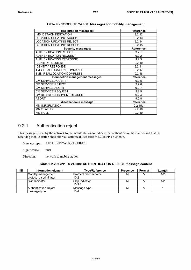
3GPP
3GPP TS 24.008 V4.17.0 (2007-09)Release 4 212
Table 9.2.1/3GPP TS 24.008: Messages for mobility management
Registration messages: Reference IMSI DETACH INDICATION 9.2.12 LOCATION UPDATING ACCEPT 9.2.13 LOCATION UPDATING REJECT 9.2.14 LOCATION UPDATING REQUEST 9.2.15
Security messages: Reference AUTHENTICATION REJECT 9.2.1 AUTHENTICATION REQUEST 9.2.2 AUTHENTICATION RESPONSE 9.2.3 IDENTITY REQUEST 9.2.10 IDENTITY RESPONSE 9.2.11 TMSI REALLOCATION COMMAND 9.2.17 TMSI REALLOCATION COMPLETE 9.2.18
Connection management messages: Reference CM SERVICE ACCEPT 9.2.5 CM SERVICE REJECT 9.2.6 CM SERVICE ABORT 9.2.7 CM SERVICE REQUEST 9.2.9 CM RE-ESTABLISHMENT REQUEST 9.2.4 ABORT 9.2.8
Miscellaneous message: Reference MM INFORMATION 9.2.15a MM STATUS 9.2.16 MM NULL 9.2.19
9.2.1 Authentication rejectThis message is sent by the network to the mobile station to indicate that authentication has failed (and that thereceiving mobile station shall abort all activities). See table 9.2.2/3GPP TS 24.008.
Message type: AUTHENTICATION REJECT
Significance: dual
Direction: network to mobile station
Table 9.2.2/3GPP TS 24.008: AUTHENTICATION REJECT message content
IEI Information element Type/Reference Presence Format LengthMobility management Protocol discriminator M V 1/2protocol discriminator 10.2Skip Indicator Skip Indicator M V 1/2
10.3.1Authentication Reject Message type M V 1message type 10.4
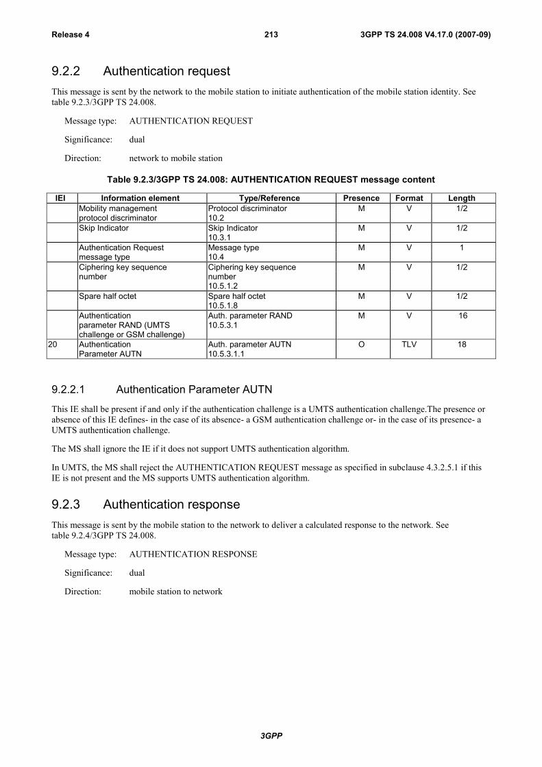
3GPP
3GPP TS 24.008 V4.17.0 (2007-09)Release 4 213
9.2.2 Authentication requestThis message is sent by the network to the mobile station to initiate authentication of the mobile station identity. Seetable 9.2.3/3GPP TS 24.008.
Message type: AUTHENTICATION REQUEST
Significance: dual
Direction: network to mobile station
Table 9.2.3/3GPP TS 24.008: AUTHENTICATION REQUEST message content
IEI Information element Type/Reference Presence Format LengthMobility management Protocol discriminator M V 1/2protocol discriminator 10.2Skip Indicator Skip Indicator M V 1/2
10.3.1Authentication Request Message type M V 1message type 10.4Ciphering key sequence Ciphering key sequence M V 1/2number number
10.5.1.2Spare half octet Spare half octet M V 1/2
10.5.1.8Authentication Auth. parameter RAND M V 16parameter RAND (UMTSchallenge or GSM challenge)
10.5.3.1
20 Authentication Auth. parameter AUTN O TLV 18Parameter AUTN 10.5.3.1.1
9.2.2.1 Authentication Parameter AUTN
This IE shall be present if and only if the authentication challenge is a UMTS authentication challenge.The presence orabsence of this IE defines- in the case of its absence- a GSM authentication challenge or- in the case of its presence- aUMTS authentication challenge.
The MS shall ignore the IE if it does not support UMTS authentication algorithm.
In UMTS, the MS shall reject the AUTHENTICATION REQUEST message as specified in subclause 4.3.2.5.1 if thisIE is not present and the MS supports UMTS authentication algorithm.
9.2.3 Authentication responseThis message is sent by the mobile station to the network to deliver a calculated response to the network. Seetable 9.2.4/3GPP TS 24.008.
Message type: AUTHENTICATION RESPONSE
Significance: dual
Direction: mobile station to network
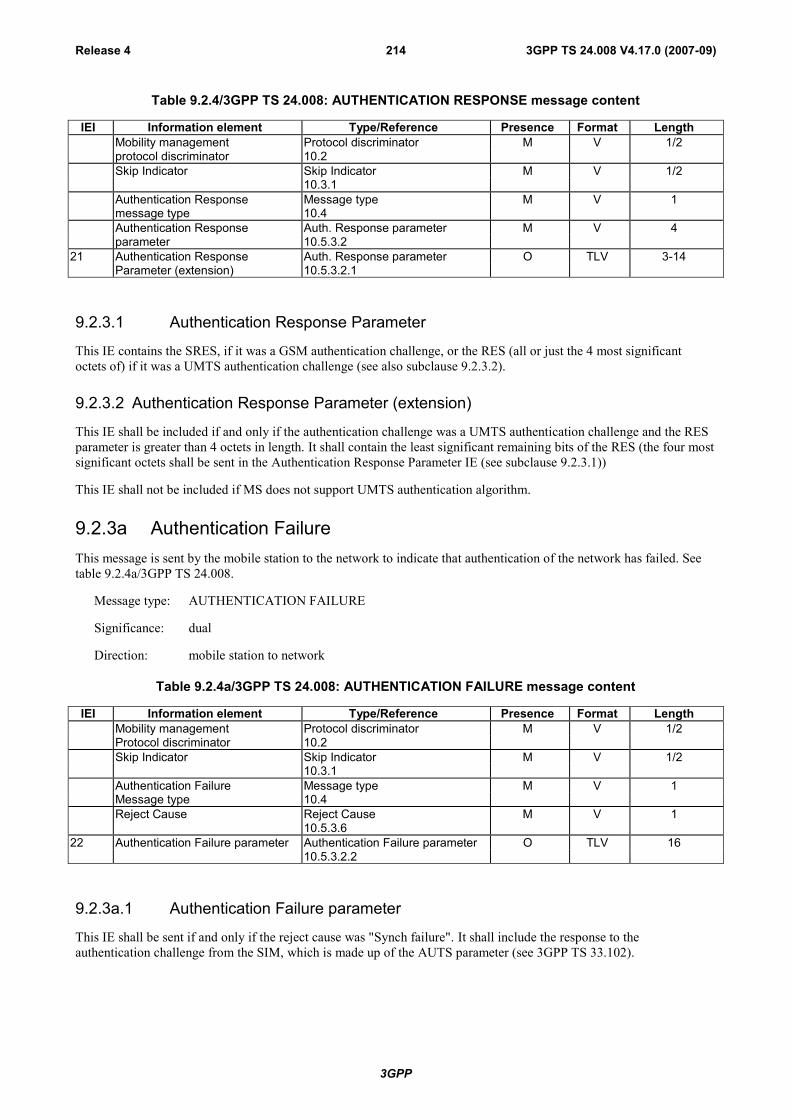
3GPP
3GPP TS 24.008 V4.17.0 (2007-09)Release 4 214
Table 9.2.4/3GPP TS 24.008: AUTHENTICATION RESPONSE message content
IEI Information element Type/Reference Presence Format LengthMobility management Protocol discriminator M V 1/2protocol discriminator 10.2Skip Indicator Skip Indicator M V 1/2
10.3.1Authentication Response Message type M V 1message type 10.4Authentication Response Auth. Response parameter M V 4parameter 10.5.3.2
21 Authentication Response Auth. Response parameter O TLV 3-14Parameter (extension) 10.5.3.2.1
9.2.3.1 Authentication Response Parameter
This IE contains the SRES, if it was a GSM authentication challenge, or the RES (all or just the 4 most significantoctets of) if it was a UMTS authentication challenge (see also subclause 9.2.3.2).
9.2.3.2 Authentication Response Parameter (extension)
This IE shall be included if and only if the authentication challenge was a UMTS authentication challenge and the RESparameter is greater than 4 octets in length. It shall contain the least significant remaining bits of the RES (the four mostsignificant octets shall be sent in the Authentication Response Parameter IE (see subclause 9.2.3.1))
This IE shall not be included if MS does not support UMTS authentication algorithm.
9.2.3a Authentication FailureThis message is sent by the mobile station to the network to indicate that authentication of the network has failed. Seetable 9.2.4a/3GPP TS 24.008.
Message type: AUTHENTICATION FAILURE
Significance: dual
Direction: mobile station to network
Table 9.2.4a/3GPP TS 24.008: AUTHENTICATION FAILURE message content
IEI Information element Type/Reference Presence Format LengthMobility management Protocol discriminator M V 1/2Protocol discriminator 10.2Skip Indicator Skip Indicator M V 1/2
10.3.1Authentication Failure Message type M V 1Message type 10.4Reject Cause Reject Cause
10.5.3.6M V 1
22 Authentication Failure parameter Authentication Failure parameter O TLV 1610.5.3.2.2
9.2.3a.1 Authentication Failure parameter
This IE shall be sent if and only if the reject cause was "Synch failure". It shall include the response to theauthentication challenge from the SIM, which is made up of the AUTS parameter (see 3GPP TS 33.102).

3GPP
3GPP TS 24.008 V4.17.0 (2007-09)Release 4 215
9.2.4 CM Re-establishment requestThis message is sent by the mobile station to the network to request re-establishment of a connection if the previous onehas failed. See table 9.2.5/3GPP TS 24.008.
Message type: CM RE-ESTABLISHMENT REQUEST
Significance: dual
Direction: mobile station to network
Table 9.2.5/3GPP TS 24.008: CM RE-ESTABLISHMENT REQUEST message content
IEI Information element Type/Reference Presence Format LengthMobility management Protocol discriminator M V ½protocol discriminator 10.2Skip Indicator Skip Indicator M V ½
10.3.1CM Re-Establishment Message type M V 1Request message type 10.4Ciphering key sequence Ciphering key sequence M V ½number number
10.5.1.2Spare half octet Spare half octet M V ½
10.5.1.8Mobile station Mobile station M LV 4classmark classmark 2
10.5.1.6Mobile identity Mobile identity M LV 2-9
10.5.1.413 Location area Location area C TV 6
identification identification10.5.1.3
9.2.4.1 Location area identification
The location area identification information element shall appear when a TMSI is used as mobile identity, to render thatmobile identity non-ambiguous. This is the LAI stored in the SIM.
9.2.4.2 Mobile Station Classmark
This IE shall include for multiband mobile station the Classmark 2 corresponding to the frequency band in use.
9.2.5 CM service acceptThis message is sent by the network to the mobile station to indicate that the requested service has been accepted. Seetable 9.2.6/3GPP TS 24.008.

3GPP
3GPP TS 24.008 V4.17.0 (2007-09)Release 4 216
Message type: CM SERVICE ACCEPT
Significance: dual
Direction: network to mobile station
Table 9.2.6/3GPP TS 24.008: CM SERVICE ACCEPT message content
IEI Information element Type/Reference Presence Format LengthMobility management Protocol discriminator M V 1/2protocol discriminator 10.2Skip Indicator Skip Indicator M V 1/2
10.3.1CM Service Accept Message type M V 1message type 10.4
9.2.5a CM service prompt $(CCBS)$A mobile station that does not support the "Network initiated MO call" option shall treat this message as a message withmessage type not defined for the PD.
This message is sent by the network to the mobile station to request the mobile to establish a service for the specifiedCM protocol using the specified SAPI, e.g. circuit switched connection establishment on SAPI 0, supplementaryservices activation on SAPI 0, or short message transfer on SAPI 3. See Table 9.2.7/3GPP TS 24.008.
Message type: CM SERVICE PROMPT
Significance: dual
Direction: network to mobile station
Table 9.2.7/3GPP TS 24.008: CM SERVICE PROMPT message content
IEI Information element Type/Reference Presence Format LengthMobility management Protocol discriminator M V 1/2protocol discriminator 10.2Skip Indicator Skip Indicator M V 1/2
10.3.1CM Service Prompt Message type M V 1message type 10.4PD and SAPI of CM PD and SAPI M V 1
10.5.1.10a
9.2.6 CM service rejectThis message is sent by the network to the mobile station to indicate that the requested service cannot be provided. Seetable 9.2.8/3GPP TS 24.008.
Message type: CM SERVICE REJECT
Significance: dual
Direction: network to mobile station
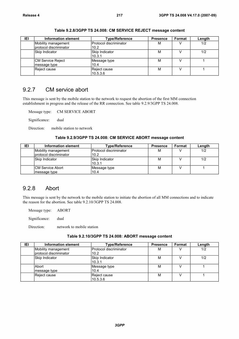
3GPP
3GPP TS 24.008 V4.17.0 (2007-09)Release 4 217
Table 9.2.8/3GPP TS 24.008: CM SERVICE REJECT message content
IEI Information element Type/Reference Presence Format LengthMobility management Protocol discriminator M V 1/2protocol discriminator 10.2Skip Indicator Skip Indicator M V 1/2
10.3.1CM Service Reject Message type M V 1message type 10.4Reject cause Reject cause M V 1
10.5.3.6
9.2.7 CM service abortThis message is sent by the mobile station to the network to request the abortion of the first MM connectionestablishment in progress and the release of the RR connection. See table 9.2.9/3GPP TS 24.008.
Message type: CM SERVICE ABORT
Significance: dual
Direction: mobile station to network
Table 9.2.9/3GPP TS 24.008: CM SERVICE ABORT message content
IEI Information element Type/Reference Presence Format LengthMobility management Protocol discriminator M V 1/2protocol discriminator 10.2Skip Indicator Skip Indicator M V 1/2
10.3.1CM Service Abort Message type M V 1message type 10.4
9.2.8 AbortThis message is sent by the network to the mobile station to initiate the abortion of all MM connections and to indicatethe reason for the abortion. See table 9.2.10/3GPP TS 24.008.
Message type: ABORT
Significance: dual
Direction: network to mobile station
Table 9.2.10/3GPP TS 24.008: ABORT message content
IEI Information element Type/Reference Presence Format LengthMobility management Protocol discriminator M V 1/2protocol discriminator 10.2Skip Indicator Skip Indicator M V 1/2
10.3.1Abort Message type M V 1message type 10.4Reject cause Reject cause M V 1
10.5.3.6

3GPP
3GPP TS 24.008 V4.17.0 (2007-09)Release 4 218
9.2.9 CM service requestThis message is sent by the mobile station to the network to request a service for the connection management sublayerentities, e.g. circuit switched connection establishment, supplementary services activation, short message transfer,location services. See table 9.2.11/3GPP TS 24.008.
Message type: CM SERVICE REQUEST
Significance: dual
Direction: mobile station to network
Table 9.2.11/3GPP TS 24.008: CM SERVICE REQUEST message content
IEI Information element Type/Reference Presence Format LengthMobility management Protocol discriminator M V ½protocol discriminator 10.2Skip Indicator Skip Indicator M V ½
10.3.1CM Service Request Message type M V 1message type 10.4CM service type CM service type M V ½
10.5.3.3Ciphering key sequence Ciphering key sequence M V ½number number
10.5.1.2Mobile station Mobile station M LV 4classmark classmark 2
10.5.1.6Mobile identity Mobile identity M LV 2-9
10.5.1.48- Priority Priority Level O TV 1
10.5.1.11
9.2.9.1 Mobile Station Classmark
This IE shall include for multiband mobile station the Classmark 2 corresponding to the frequency band in use.
9.2.9.2 Priority
May be included by mobile station supporting eMLPP to indicate the priority requested.
This information element is only meaningful when the CM service type is:
Mobile originating call establishment;
Emergency call establishment;
Voice group call establishment;
Voice broadcast call establishment.
9.2.10 Identity requestThis message is sent by the network to the mobile station to request a mobile station to submit the specified identity tothe network. See table 9.2.12/3GPP TS 24.008.
Message type: IDENTITY REQUEST
Significance: dual
Direction: network to mobile station

3GPP
3GPP TS 24.008 V4.17.0 (2007-09)Release 4 219
Table 9.2.12/3GPP TS 24.008: IDENTITY REQUEST message content
IEI Information element Type/Reference Presence Format LengthMobility management Protocol discriminator M V 1/2protocol discriminator 10.2Skip Indicator Skip Indicator M V 1/2
10.3.1Identity Request Message type M V 1message type 10.4Identity type Identity type M V 1/2
10.5.3.4Spare half octet Spare half octet M V 1/2
10.5.1.8
9.2.11 Identity responseThis message is sent by the mobile station to the network in response to an IDENTITY REQUEST message providingthe requested identity. See table 9.2.13/3GPP TS 24.008.
Message type: IDENTITY RESPONSE
Significance: dual
Direction: mobile station to network
Table 9.2.13/3GPP TS 24.008: IDENTITY RESPONSE message content
IEI Information element Type/Reference Presence Format LengthMobility management Protocol discriminator M V 1/2protocol discriminator 10.2Skip Indicator Skip Indicator M V 1/2
10.3.1Identity Response Message type M V 1message type 10.4Mobile identity Mobile identity M LV 2-10
10.5.1.4
9.2.12 IMSI detach indicationThis message is sent by the mobile station to the network to set a deactivation indication in the network. Seetable 9.2.14/3GPP TS 24.008.
Message type: IMSI DETACH INDICATION
Significance: dual
Direction: mobile station to network
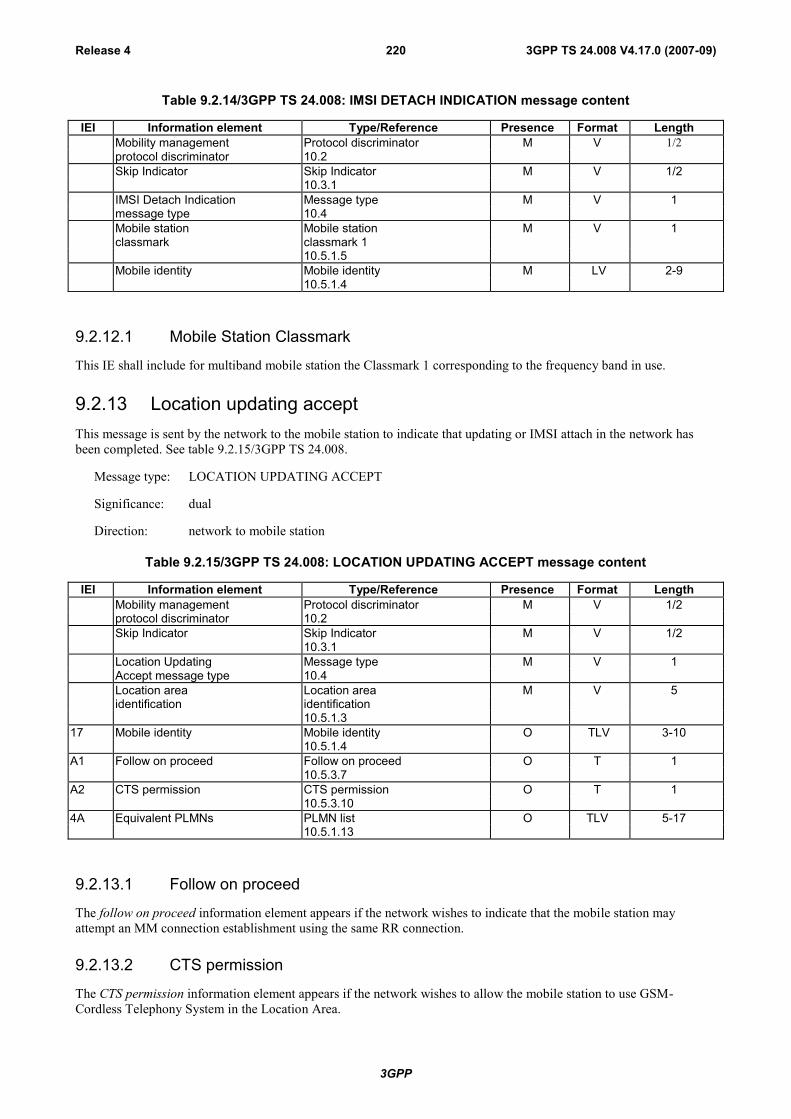
3GPP
3GPP TS 24.008 V4.17.0 (2007-09)Release 4 220
Table 9.2.14/3GPP TS 24.008: IMSI DETACH INDICATION message content
IEI Information element Type/Reference Presence Format LengthMobility management Protocol discriminator M V 1/2protocol discriminator 10.2Skip Indicator Skip Indicator M V 1/2
10.3.1IMSI Detach Indication Message type M V 1message type 10.4Mobile station Mobile station M V 1classmark classmark 1
10.5.1.5Mobile identity Mobile identity M LV 2-9
10.5.1.4
9.2.12.1 Mobile Station Classmark
This IE shall include for multiband mobile station the Classmark 1 corresponding to the frequency band in use.
9.2.13 Location updating acceptThis message is sent by the network to the mobile station to indicate that updating or IMSI attach in the network hasbeen completed. See table 9.2.15/3GPP TS 24.008.
Message type: LOCATION UPDATING ACCEPT
Significance: dual
Direction: network to mobile station
Table 9.2.15/3GPP TS 24.008: LOCATION UPDATING ACCEPT message content
IEI Information element Type/Reference Presence Format LengthMobility management Protocol discriminator M V 1/2protocol discriminator 10.2Skip Indicator Skip Indicator M V 1/2
10.3.1Location Updating Message type M V 1Accept message type 10.4Location area Location area M V 5identification identification
10.5.1.317 Mobile identity Mobile identity O TLV 3-10
10.5.1.4A1 Follow on proceed Follow on proceed O T 1
10.5.3.7A2 CTS permission CTS permission O T 1
10.5.3.104A Equivalent PLMNs PLMN list O TLV 5-17
10.5.1.13
9.2.13.1 Follow on proceed
The follow on proceed information element appears if the network wishes to indicate that the mobile station mayattempt an MM connection establishment using the same RR connection.
9.2.13.2 CTS permission
The CTS permission information element appears if the network wishes to allow the mobile station to use GSM-Cordless Telephony System in the Location Area.

3GPP
3GPP TS 24.008 V4.17.0 (2007-09)Release 4 221
9.2.13.3 Equivalent PLMNs
The Equivalent PLMNs information element is included if the network wants to inform the mobile station of equivalentPLMNs.
9.2.14 Location updating rejectThis message is sent by the network to the mobile station to indicate that updating or IMSI attach has failed. Seetable 9.2.16/3GPP TS 24.008.
Message type: LOCATION UPDATING REJECT
Significance: dual
Direction: network to mobile station
Table 9.2.16/3GPP TS 24.008: LOCATION UPDATING REJECT message content
IEI Information element Type/Reference Presence Format LengthMobility management Protocol discriminator M V 1/2protocol discriminator 10.2Skip Indicator Skip Indicator M V 1/2
10.3.1Location Updating Message type M V 1Reject message type 10.4Reject cause Reject cause M V 1
10.5.3.6
9.2.15 Location updating requestThis message is sent by the mobile station to the network either to request update of its location file (normal updating orperiodic updating) or to request IMSI attach. See table 9.2.17/3GPP TS 24.008.
Message type: LOCATION UPDATING REQUEST
Significance: dual
Direction: mobile station to network

3GPP
3GPP TS 24.008 V4.17.0 (2007-09)Release 4 222
Table 9.2.17/3GPP TS 24.008: LOCATION UPDATING REQUEST message content
IEI Information element Type/Reference Presence Format LengthMobility management Protocol discriminator M V 1/2protocol discriminator 10.2Skip Indicator Skip Indicator M V 1/2
10.3.1Location Updating Message type M V 1Request message type 10.4Location updating type Location updating type M V 1/2
10.5.3.5Ciphering key sequence Ciphering key sequence M V 1/2number number
10.5.1.2Location area Location area M V 5identification identification
10.5.1.3Mobile station Mobile station M V 1classmark classmark 1
10.5.1.5Mobile identity Mobile identity M LV 2-9
10.5.1.433 Mobile station Mobile station O TLV 5
classmark for UMTS classmark 210.5.1.6
9.2.15.1 Location area identification
The location area identification stored in the SIM is used.
9.2.15.2 Mobile Station Classmark
This IE shall include for multiband MS the Classmark 1 corresponding to the frequency band in use.
9.2.15.3 Mobile Station Classmark for UMTS
This IE shall be included when the mobile station is in UMTS network. The IE shall not be included when the mobilestation is in GSM network.
9.2.15a MM informationThis message is sent by the network to the mobile station to provide the mobile station with subscriber specificinformation. See table 9.2.18/3GPP TS 24.008.
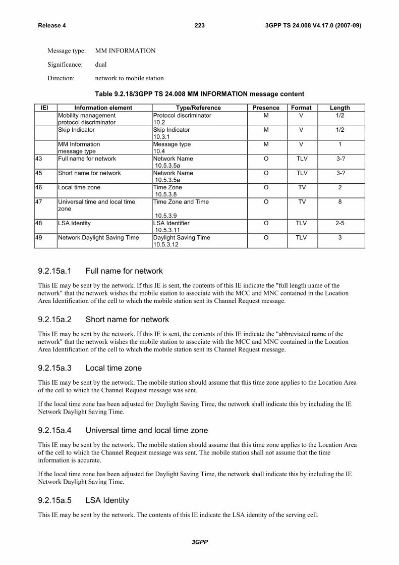
3GPP
3GPP TS 24.008 V4.17.0 (2007-09)Release 4 223
Message type: MM INFORMATION
Significance: dual
Direction: network to mobile station
Table 9.2.18/3GPP TS 24.008 MM INFORMATION message content
IEI Information element Type/Reference Presence Format LengthMobility management Protocol discriminator M V 1/2protocol discriminator 10.2Skip Indicator Skip Indicator M V 1/2
10.3.1MM Information Message type M V 1message type 10.4
43 Full name for network Network Name O TLV 3-? 10.5.3.5a
45 Short name for network Network Name O TLV 3-? 10.5.3.5a
46 Local time zone Time Zone O TV 2 10.5.3.8
47 Universal time and local timezone
Time Zone and Time O TV 8
10.5.3.948 LSA Identity LSA Identifier
10.5.3.11O TLV 2-5
49 Network Daylight Saving Time Daylight Saving Time O TLV 310.5.3.12
9.2.15a.1 Full name for network
This IE may be sent by the network. If this IE is sent, the contents of this IE indicate the "full length name of thenetwork" that the network wishes the mobile station to associate with the MCC and MNC contained in the LocationArea Identification of the cell to which the mobile station sent its Channel Request message.
9.2.15a.2 Short name for network
This IE may be sent by the network. If this IE is sent, the contents of this IE indicate the "abbreviated name of thenetwork" that the network wishes the mobile station to associate with the MCC and MNC contained in the LocationArea Identification of the cell to which the mobile station sent its Channel Request message.
9.2.15a.3 Local time zone
This IE may be sent by the network. The mobile station should assume that this time zone applies to the Location Areaof the cell to which the Channel Request message was sent.
If the local time zone has been adjusted for Daylight Saving Time, the network shall indicate this by including the IENetwork Daylight Saving Time.
9.2.15a.4 Universal time and local time zone
This IE may be sent by the network. The mobile station should assume that this time zone applies to the Location Areaof the cell to which the Channel Request message was sent. The mobile station shall not assume that the timeinformation is accurate.
If the local time zone has been adjusted for Daylight Saving Time, the network shall indicate this by including the IENetwork Daylight Saving Time.
9.2.15a.5 LSA Identity
This IE may be sent by the network. The contents of this IE indicate the LSA identity of the serving cell.

3GPP
3GPP TS 24.008 V4.17.0 (2007-09)Release 4 224
9.2.15a.6 Network Daylight Saving Time
This IE may be sent by the network. If this IE is sent, the contents of this IE indicates the value that has been used toadjust the local time zone.
9.2.16 MM StatusThis message is sent by the mobile station or the network at any time to report certain error conditions listed in clause 8.See table 9.2.19/3GPP TS 24.008.
Message type: MM STATUS
Significance: local
Direction: both
Table 9.2.19/3GPP TS 24.008: MM STATUS message content
IEI Information element Type/Reference Presence Format LengthMobility management Protocol discriminator M V 1/2protocol discriminator 10.2Skip Indicator Skip Indicator M V 1/2
10.3.1MM Status message Message type M V 1type 10.4Reject cause Reject cause M V 1
10.5.3.6
9.2.17 TMSI reallocation commandThis message is sent by the network to the mobile station to reallocate or delete a TMSI. See table 9.2.20/3GPP TS24.008.
Message type: TMSI REALLOCATION COMMAND
Significance: dual
Direction: network to mobile station
Table 9.2.20/3GPP TS 24.008: TMSI REALLOCATION COMMAND message content
IEI Information element Type/Reference Presence Format LengthMobility management Protocol discriminator M V 1/2protocol discriminator 10.2Skip Indicator Skip Indicator M V 1/2
10.3.1TMSI Reallocation Message type M V 1Command message type 10.4Location area Location area M V 5identification identification
10.5.1.3Mobile identity Mobile identity M LV 2-9
10.5.1.4

3GPP
3GPP TS 24.008 V4.17.0 (2007-09)Release 4 225
9.2.18 TMSI reallocation completeThis message is sent by the mobile station to the network to indicate that reallocation or deletion of a TMSI has takenplace. See table 9.2.21/3GPP TS 24.008.
Message type: TMSI REALLOCATION COMPLETE
Significance: dual
Direction: mobile station to network
Table 9.2.21/3GPP TS 24.008: TMSI REALLOCATION COMPLETE message content
IEI Information element Type/Reference Presence Format LengthMobility management Protocol discriminator M V 1/2protocol discriminator 10.2Skip Indicator Skip Indicator M V 1/2
10.3.1TMSI Reallocation Message type M V 1Complete message type 10.4
9.2.19 MM NullThis message is sent in mobile to network direction.
This message is not used on the radio interface. When received by the network it shall be ignored.
The introduction of this message solves interworking issues.
Message type: MM NULL
Table 9.2.22/3GPP TS 24.008 MM NULL message content
IEI Information element Type/Reference Presence Format LengthMobility management Protocol discriminator M V 1/2protocol discriminator 10.2Skip Indicator Skip Indicator M V 1/2
10.3.1MM Null message Message type M V 1type 10.4
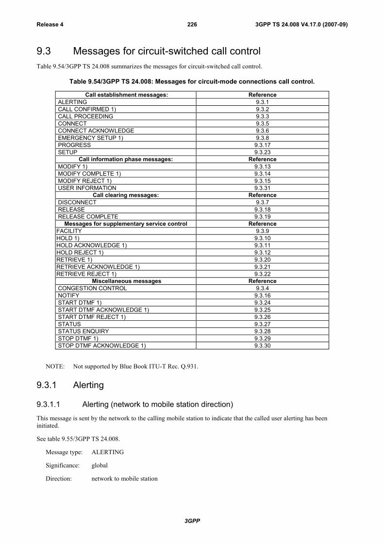
3GPP
3GPP TS 24.008 V4.17.0 (2007-09)Release 4 226
9.3 Messages for circuit-switched call controlTable 9.54/3GPP TS 24.008 summarizes the messages for circuit-switched call control.
Table 9.54/3GPP TS 24.008: Messages for circuit-mode connections call control.
Call establishment messages: Reference ALERTING 9.3.1 CALL CONFIRMED 1) 9.3.2 CALL PROCEEDING 9.3.3 CONNECT 9.3.5 CONNECT ACKNOWLEDGE 9.3.6 EMERGENCY SETUP 1) 9.3.8 PROGRESS 9.3.17 SETUP 9.3.23
Call information phase messages: Reference MODIFY 1) 9.3.13 MODIFY COMPLETE 1) 9.3.14 MODIFY REJECT 1) 9.3.15 USER INFORMATION 9.3.31
Call clearing messages: Reference DISCONNECT 9.3.7 RELEASE 9.3.18 RELEASE COMPLETE 9.3.19
Messages for supplementary service control ReferenceFACILITY 9.3.9HOLD 1) 9.3.10HOLD ACKNOWLEDGE 1) 9.3.11HOLD REJECT 1) 9.3.12RETRIEVE 1) 9.3.20RETRIEVE ACKNOWLEDGE 1) 9.3.21RETRIEVE REJECT 1) 9.3.22
Miscellaneous messages Reference CONGESTION CONTROL 9.3.4 NOTIFY 9.3.16 START DTMF 1) 9.3.24 START DTMF ACKNOWLEDGE 1) 9.3.25 START DTMF REJECT 1) 9.3.26 STATUS 9.3.27 STATUS ENQUIRY 9.3.28 STOP DTMF 1) 9.3.29 STOP DTMF ACKNOWLEDGE 1) 9.3.30
NOTE: Not supported by Blue Book ITU-T Rec. Q.931.
9.3.1 Alerting
9.3.1.1 Alerting (network to mobile station direction)
This message is sent by the network to the calling mobile station to indicate that the called user alerting has beeninitiated.
See table 9.55/3GPP TS 24.008.
Message type: ALERTING
Significance: global
Direction: network to mobile station

3GPP
3GPP TS 24.008 V4.17.0 (2007-09)Release 4 227
Table 9.55/3GPP TS 24.008: ALERTING message content (network to mobile station direction)
IEI Information element Type/Reference Presence Format LengthCall control Protocol discriminator M V 1/2protocol discriminator 10.2Transaction identifier Transaction identifier M V 1/2
10.3.2Alerting Message type M V 1message type 10.4
1C Facility Facility O TLV 2-?10.5.4.15
1E Progress indicator Progress indicator O TLV 410.5.4.21
7E User-user User-user O TLV 3-131 10.5.4.25
9.3.1.1.1 Facility
This information element may be used for functional operation of supplementary services.
9.3.1.1.2 Progress indicator
This information element may be included by the network:
- in order to pass information about the call in progress, e.g., in the event of interworking; and/or
- to make the mobile station attach the user connection for speech.
9.3.1.1.3 User-user
This information element may be included by the network if the called remote user included a user-user informationelement in the ALERTING message.
9.3.1.2 Alerting (mobile station to network direction)
This message is sent by the called mobile station to the network, to indicate that the called user alerting has beeninitiated.
See table 9.55a/3GPP TS 24.008.
Message type: ALERTING
Significance: global
Direction: mobile station to network
Table 9.55a/3GPP TS 24.008: ALERTING message content (mobile station to network direction)
IEI Information element Type/Reference Presence Format LengthCall control Protocol discriminator M V 1/2protocol discriminator 10.2Transaction identifier Transaction identifier M V 1/2
10.3.2Alerting Message type M V 1message type 10.4
1C Facility Facility O TLV 2-? 10.5.4.15
7E User-user User-user O TLV 3-13110.5.4.25
7F SS version SS version indicator O TLV 2-310.5.4.24
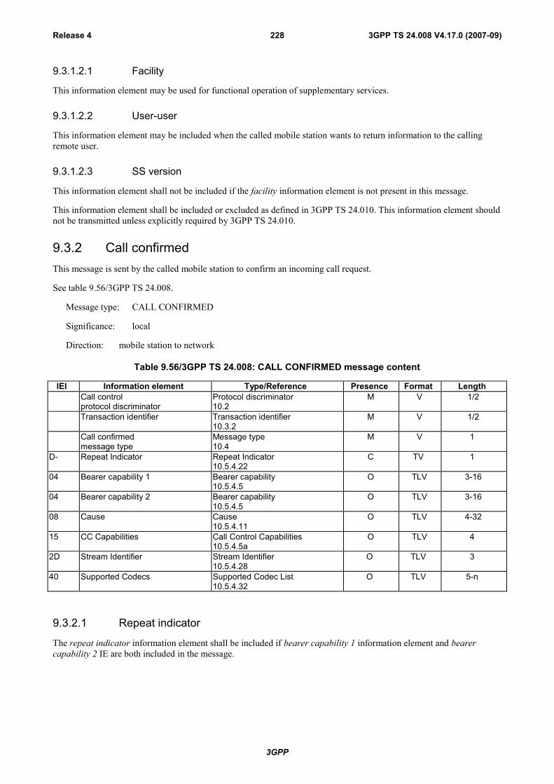
3GPP
3GPP TS 24.008 V4.17.0 (2007-09)Release 4 228
9.3.1.2.1 Facility
This information element may be used for functional operation of supplementary services.
9.3.1.2.2 User-user
This information element may be included when the called mobile station wants to return information to the callingremote user.
9.3.1.2.3 SS version
This information element shall not be included if the facility information element is not present in this message.
This information element shall be included or excluded as defined in 3GPP TS 24.010. This information element shouldnot be transmitted unless explicitly required by 3GPP TS 24.010.
9.3.2 Call confirmedThis message is sent by the called mobile station to confirm an incoming call request.
See table 9.56/3GPP TS 24.008.
Message type: CALL CONFIRMED
Significance: local
Direction: mobile station to network
Table 9.56/3GPP TS 24.008: CALL CONFIRMED message content
IEI Information element Type/Reference Presence Format LengthCall control Protocol discriminator M V 1/2protocol discriminator 10.2Transaction identifier Transaction identifier M V 1/2
10.3.2Call confirmed Message type M V 1message type 10.4
D- Repeat Indicator Repeat Indicator C TV 110.5.4.22
04 Bearer capability 1 Bearer capability O TLV 3-1610.5.4.5
04 Bearer capability 2 Bearer capability O TLV 3-1610.5.4.5
08 Cause Cause O TLV 4-3210.5.4.11
15 CC Capabilities Call Control Capabilities O TLV 410.5.4.5a
2D Stream Identifier Stream Identifier O TLV 310.5.4.28
40 Supported Codecs Supported Codec List O TLV 5-n10.5.4.32
9.3.2.1 Repeat indicator
The repeat indicator information element shall be included if bearer capability 1 information element and bearercapability 2 IE are both included in the message.

3GPP
3GPP TS 24.008 V4.17.0 (2007-09)Release 4 229
9.3.2.2 Bearer capability 1 and bearer capability 2
The bearer capability 1 information element shall be included if and only if at least one of the following six casesholds:
- the mobile station wishes another bearer capability than that given by the bearer capability 1 informationelement of the incoming SETUP message;
- the bearer capability 1 information element is missing or not fully specified in the SETUP message;
- the bearer capability 1 information element received in the SETUP message is accepted and the "radio channelrequirement" of the mobile station is other than "full rate support only mobile station";
- the bearer capability 1 information element received in the SETUP message indicates speech and is acceptedand the mobile station supports CTM text telephony;
- the bearer capability 1 information element received in the SETUP message indicates speech and is acceptedand the mobile station supports other GSM codecs than GSM speech version 1;
- the bearer capability 1 information element received in the SETUP message included the "fixed network userrate" parameter.
When the bearer capability 1 information element is followed by the bearer capability 2 IE in the SETUP, the aboverules apply to both bearer capability 1 IE and bearer capability 2 IE. Except those cases identified in 3GPP TS 27.001,if either bearer capability needs to be included, both shall be included.
Furthermore, both bearer capability information elements may be present if the mobile station wishes to reverse theorder of occurrence of the bearer capability information elements (which is referred to in the repeat indicatorinformation element, see subclause 10.5.4.22) in cases identified in 3GPP TS 27.001 [36].
If the mobile station wishes to indicate capability for an alternative call mode, which can be entered during the callthrough in-call modification, this is indicated by adding a bearer capability information element (bearer capability) 2element (see subclause 5.3.6).
9.3.2.3 Cause
This information element is included if the mobile station is compatible but the user is busy.
9.3.2.4 CC Capabilities
This information element may be included by the mobile station to indicate its call control capabilities.
9.3.2.5 Stream Identifier
This information element shall be included by the mobile station supporting multicall.
9.3.2.6 Supported Codecs
This information element shall be included for speech calls, if the mobile station supports UMTS radio access.
9.3.3 Call proceedingThis message is sent by the network to the calling mobile station to indicate that the requested call establishmentinformation has been received, and no more call establishment information will be accepted.
See table 9.57/3GPP TS 24.008.
Message type: CALL PROCEEDING
Significance: local
Direction: network to mobile station

3GPP
3GPP TS 24.008 V4.17.0 (2007-09)Release 4 230
Table 9.57/3GPP TS 24.008: CALL PROCEEDING message content
IEI Information element Type/Reference Presence Format LengthCall control Protocol discriminator M V 1/2protocol discriminator 10.2Transaction identifier Transaction identifier M V 1/2
10.3.2Call proceeding Message type M V 1message type 10.4
D- Repeat Indicator Repeat Indicator C TV 110.5.4.22
04 Bearer capability 1 Bearer capability O TLV 3-1610.5.4.5
04 Bearer capability 2 Bearer capability O TLV 3-1610.5.4.5
1C Facility Facility O TLV 2-?10.5.4.15
1E Progress indicator Progress indicator O TLV 410.5.4.21
8- Priority granted Priority Level O TV 110.5.1.11
2F Network Call Control Network Call Control cap. O TLV 3Capabilities 10.5.4.29
9.3.3.1 Repeat indicator
This information element is included if and only if bearer capability 1 IE and bearer capability 2 IE are both containedin the message.
9.3.3.2 Bearer capability 1 and bearer capability 2
The bearer capability 1 information element is included if the network has to specify at least one of the negotiableparameters described in 3GPP TS 27.001, or if the bearer capability 1 information element received in the SETUPmessage included the "fixed network user rate" parameter.
When the bearer capability 1 information element is followed by the bearer capability 2 IE in the SETUP, the aboverule applies to both bearer capability 1 IE and bearer capability 2 IE. Except those cases identified in3GPP TS 27.001 [36], if either bearer capability needs to be included, both shall be included.
9.3.3.3 Facility
This information element may be used for functional operation of supplementary services.
9.3.3.4 Progress Indicator
This information element may be included:
- in order to pass information about the call in progress e.g. in the event of interworking; and/or
- to make the MS attach the user connection for speech.
9.3.3.5 Priority granted
The priority field is provided by the network in the case that eMLPP is supported.
9.3.3.6 Network Call Control Capabilities
This information shall be included by the network to indicate its call control capabilities if the network supportsmulticall.and there are no other ongoing calls to the MS.
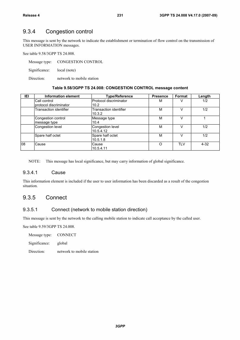
3GPP
3GPP TS 24.008 V4.17.0 (2007-09)Release 4 231
9.3.4 Congestion controlThis message is sent by the network to indicate the establishment or termination of flow control on the transmission ofUSER INFORMATION messages.
See table 9.58/3GPP TS 24.008.
Message type: CONGESTION CONTROL
Significance: local (note)
Direction: network to mobile station
Table 9.58/3GPP TS 24.008: CONGESTION CONTROL message content
IEI Information element Type/Reference Presence Format LengthCall control Protocol discriminator M V 1/2protocol discriminator 10.2Transaction identifier Transaction identifier M V 1/2
10.3.2Congestion control Message type M V 1message type 10.4Congestion level Congestion level M V 1/2
10.5.4.12Spare half octet Spare half octet M V 1/2
10.5.1.808 Cause Cause O TLV 4-32
10.5.4.11
NOTE: This message has local significance, but may carry information of global significance.
9.3.4.1 Cause
This information element is included if the user to user information has been discarded as a result of the congestionsituation.
9.3.5 Connect
9.3.5.1 Connect (network to mobile station direction)
This message is sent by the network to the calling mobile station to indicate call acceptance by the called user.
See table 9.59/3GPP TS 24.008.
Message type: CONNECT
Significance: global
Direction: network to mobile station

3GPP
3GPP TS 24.008 V4.17.0 (2007-09)Release 4 232
Table 9.59/3GPP TS 24.008: CONNECT message content(network to mobile station direction)
IEI Information element Type/Reference Presence Format LengthCall control Protocol discriminator M V 1/2protocol discriminator 10.2Transaction identifier Transaction identifier M V 1/2
10.3.2Connect Message type M V 1message type 10.4
1C Facility Facility O TLV 2-?10.5.4.15
1E Progress indicator Progress indicator O TLV 410.5.4.21
4C Connected number Connected number O TLV 3-1410.5.4.13
4D Connected subaddress Connected subaddress O TLV 2-2310.5.4.14
7E User-user User-user O TLV 3-13110.5.4.25
9.3.5.1.1 Facility
This information element may be used for functional operation of supplementary services.
9.3.5.1.2 Progress indicator
This information element may be included by the network:
- in order to pass information about the call in progress e.g. in the event of interworking; and/or
- to make the MS attach the user connection for speech.
9.3.5.1.3 User-user
This information element may be included by the network if the remote user awarded the call included a user- userinformation element in the CONNECT message.
9.3.5.2 Connect (mobile station to network direction)
This message is sent by the called mobile station to the network to indicate call acceptance by the called user.
See table 9.59a/3GPP TS 24.008.
Message type: CONNECT
Significance: global
Direction: mobile station to network

3GPP
3GPP TS 24.008 V4.17.0 (2007-09)Release 4 233
Table 9.59a/3GPP TS 24.008: CONNECT message content (mobile station to network direction)
IEI Information element Type/Reference Presence Format LengthCall control Protocol discriminator M V 1/2protocol discriminator 10.2Transaction identifier Transaction identifier M V 1/2
10.3.2Connect Message type M V 1message type 10.4
1C Facility Facility O TLV 2-?10.5.4.15
4D Connected subaddress Connected subaddress O TLV 2-2310.5.4.14
7E User-user User-user O TLV 3-13110.5.4.25
7F SS version SS version indicator O TLV 2-310.5.4.24
2D Stream Identifier Stream Identifier O TLV 310.5.4.28
9.3.5.2.1 Facility
This information element may be used for functional operation of supplementary services.
9.3.5.2.2 User-user
This information element is included when the answering mobile station wants to return user information to the callingremote user.
9.3.5.2.3 SS version
This information element shall not be included if the facility information element is not present in this message.
This information element shall be included or excluded as defined in 3GPP TS 24.010. This information element shouldnot be transmitted unless explicitly required by 3GPP TS 24.010.
9.3.5.2.4 Stream Identifier
This information element shall be included by a mobile station that supports multicall when a mobile station hasindicated "No Bearer" as the SI value in the CALL CONFIRMED message.
9.3.6 Connect acknowledgeThis message is sent by the network to the called mobile station to indicate that the mobile station has been awarded thecall. It shall also be sent by the calling mobile station to the network to acknowledge the offered connection.
See table 9.60/3GPP TS 24.008.
Message type: CONNECT ACKNOWLEDGE
Significance: local
Direction: both

3GPP
3GPP TS 24.008 V4.17.0 (2007-09)Release 4 234
Table 9.60/3GPP TS 24.008: CONNECT ACKNOWLEDGE message content
IEI Information element Type/Reference Presence Format LengthCall control Protocol discriminator M V 1/2protocol discriminator 10.2Transaction identifier Transaction identifier M V 1/2
10.3.2Connect acknowledge Message type M V 1message type 10.4
9.3.7 Disconnect
9.3.7.1 Disconnect (network to mobile station direction)
This message is sent by the network to indicate that the end-to-end connection is cleared.
See table 9.61/3GPP TS 24.008.
Message type: DISCONNECT
Significance: global
Direction: network to mobile station
Table 9.61/3GPP TS 24.008: DISCONNECT message content (network to mobile station direction)
IEI Information element Type/Reference Presence Format LengthCall control Protocol discriminator M V 1/2protocol discriminator 10.2Transaction identifier Transaction identifier M V 1/2
10.3.2Disconnect Message type M V 1message type 10.4Cause Cause M LV 3-31
10.5.4.111C Facility Facility O TLV 2-?
10.5.4.151E Progress indicator Progress indicator O TLV 4
10.5.4.217E User-user User-user O TLV 3-131
10.5.4.257B Allowed actions $(CCBS)$ Allowed actions O TLV 3
10.5.4.27
9.3.7.1.1 Facility
This information element may be used for functional operation of supplementary services, such as the user-user service.
9.3.7.1.2 Progress indicator
This information element is included by the network to make the MS attach the user connection for speech and react ina specific way during call clearing (see subclause 5.4.4).
9.3.7.1.3 User-user
This information element may be included by the network when the remote user initiates call clearing and included auser-user information element in the DISCONNECT message.
9.3.7.1.4 Allowed actions $(CCBS)$
This information element may be included by the network to inform the MS about further possible reactions.
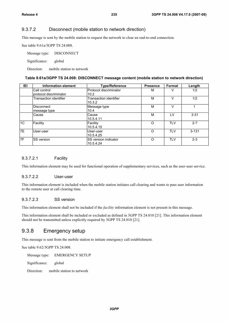
3GPP
3GPP TS 24.008 V4.17.0 (2007-09)Release 4 235
9.3.7.2 Disconnect (mobile station to network direction)
This message is sent by the mobile station to request the network to clear an end-to-end connection.
See table 9.61a/3GPP TS 24.008.
Message type: DISCONNECT
Significance: global
Direction: mobile station to network
Table 9.61a/3GPP TS 24.008: DISCONNECT message content (mobile station to network direction)
IEI Information element Type/Reference Presence Format LengthCall control Protocol discriminator M V 1/2protocol discriminator 10.2Transaction identifier Transaction identifier M V 1/2
10.3.2Disconnect Message type M V 1message type 10.4Cause Cause M LV 3-31
10.5.4.111C Facility Facility O TLV 2-?
10.5.4.157E User-user User-user O TLV 3-131
10.5.4.257F SS version SS version indicator O TLV 2-3
10.5.4.24
9.3.7.2.1 Facility
This information element may be used for functional operation of supplementary services, such as the user-user service.
9.3.7.2.2 User-user
This information element is included when the mobile station initiates call clearing and wants to pass user informationto the remote user at call clearing time.
9.3.7.2.3 SS version
This information element shall not be included if the facility information element is not present in this message.
This information element shall be included or excluded as defined in 3GPP TS 24.010 [21]. This information elementshould not be transmitted unless explicitly required by 3GPP TS 24.010 [21].
9.3.8 Emergency setupThis message is sent from the mobile station to initiate emergency call establishment.
See table 9.62/3GPP TS 24.008.
Message type: EMERGENCY SETUP
Significance: global
Direction: mobile station to network
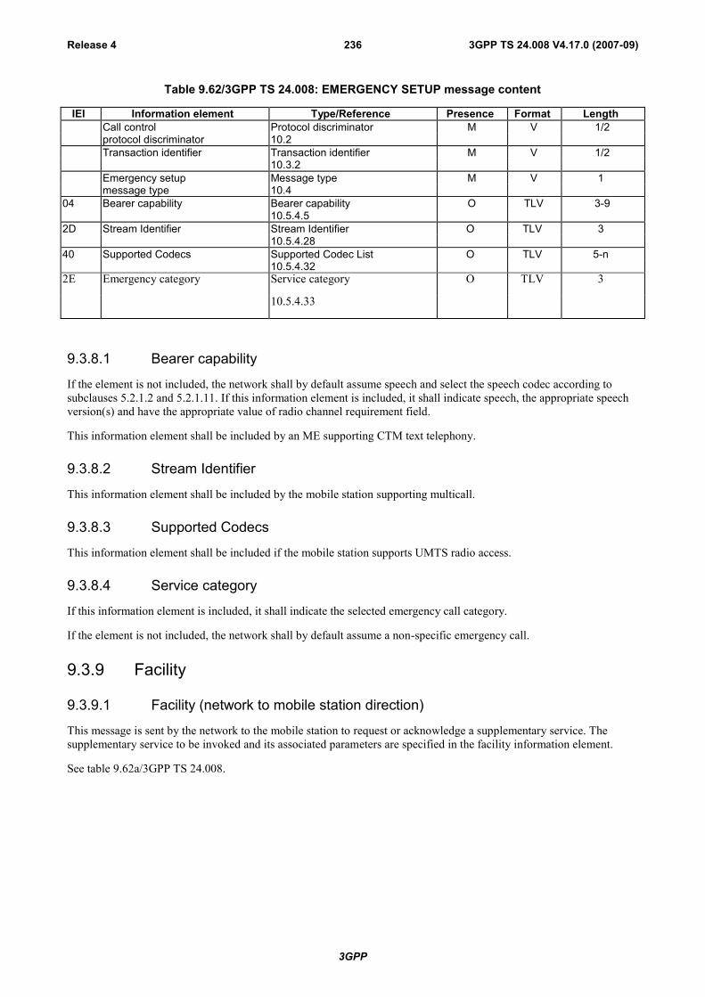
3GPP
3GPP TS 24.008 V4.17.0 (2007-09)Release 4 236
Table 9.62/3GPP TS 24.008: EMERGENCY SETUP message content
IEI Information element Type/Reference Presence Format LengthCall control Protocol discriminator M V 1/2protocol discriminator 10.2Transaction identifier Transaction identifier M V 1/2
10.3.2Emergency setup Message type M V 1message type 10.4
04 Bearer capability Bearer capability O TLV 3-910.5.4.5
2D Stream Identifier Stream Identifier O TLV 310.5.4.28
40 Supported Codecs Supported Codec List O TLV 5-n10.5.4.32
2E Emergency category Service category O TLV 3
10.5.4.33
9.3.8.1 Bearer capability
If the element is not included, the network shall by default assume speech and select the speech codec according tosubclauses 5.2.1.2 and 5.2.1.11. If this information element is included, it shall indicate speech, the appropriate speechversion(s) and have the appropriate value of radio channel requirement field.
This information element shall be included by an ME supporting CTM text telephony.
9.3.8.2 Stream Identifier
This information element shall be included by the mobile station supporting multicall.
9.3.8.3 Supported Codecs
This information element shall be included if the mobile station supports UMTS radio access.
9.3.8.4 Service category
If this information element is included, it shall indicate the selected emergency call category.
If the element is not included, the network shall by default assume a non-specific emergency call.
9.3.9 Facility
9.3.9.1 Facility (network to mobile station direction)
This message is sent by the network to the mobile station to request or acknowledge a supplementary service. Thesupplementary service to be invoked and its associated parameters are specified in the facility information element.
See table 9.62a/3GPP TS 24.008.

3GPP
3GPP TS 24.008 V4.17.0 (2007-09)Release 4 237
Message type: FACILITY
Significance: local (NOTE 1)
Direction: network to mobile station
Table 9.62a/3GPP TS 24.008: FACILITY message content (network to mobile station direction)
IEI Information element Type/Reference Presence Format LengthCall control Protocol discriminator M V 1/2protocol discriminator 10.2Transaction identifier Transaction identifier M V 1/2
10.3.2Facility Message type M V 1message type 10.4Facility (note 2) Facility M LV 1-?
10.5.4.15
NOTE 1: This message has local significance; however, it may carry information of global significance.
NOTE 2: The facility information element has no upper length limit except that given by the maximum number ofoctets in a L3 message, see 3GPP TS 44.006 [19].
9.3.9.2 Facility (mobile station to network direction)
This message is sent by the mobile station to the network to request or acknowledge a supplementary service. Thesupplementary service to be invoked and its associated parameters are specified in the facility information element.
See table 9.62b/3GPP TS 24.008.
Message type: FACILITY
Significance: local (note 1)
Direction: mobile station to network
Table 9.62b/3GPP TS 24.008: FACILITY message content (mobile station to network direction)
IEI Information element Type/Reference Presence Format LengthCall control Protocol discriminator M V 1/2protocol discriminator 10.2Transaction identifier Transaction identifier M V 1/2
10.3.2Facility Message type M V 1message type 10.4Facility (note 2) Facility M LV 1-?
10.5.4.157F SS version SS version indicator O TLV 2-3
10.5.4.24
NOTE 1: This message has local significance; however, it may carry information of global significance.
NOTE 2: The facility information element has no upper length limit except that given by the maximum number ofoctets in a L3 message, see 3GPP TS 44.006.
9.3.9.2.1 SS version
This information element shall be included or excluded as defined in 3GPP TS 24.010 [21]. This information elementshould not be transmitted unless explicitly required by 3GPP TS 24.010 [21].
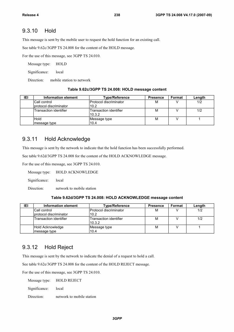
3GPP
3GPP TS 24.008 V4.17.0 (2007-09)Release 4 238
9.3.10 HoldThis message is sent by the mobile user to request the hold function for an existing call.
See table 9.62c/3GPP TS 24.008 for the content of the HOLD message.
For the use of this message, see 3GPP TS 24.010.
Message type: HOLD
Significance: local
Direction: mobile station to network
Table 9.62c/3GPP TS 24.008: HOLD message content
IEI Information element Type/Reference Presence Format LengthCall control Protocol discriminator M V 1/2protocol discriminator 10.2Transaction identifier Transaction identifier M V 1/2
10.3.2Hold Message type M V 1message type 10.4
9.3.11 Hold AcknowledgeThis message is sent by the network to indicate that the hold function has been successfully performed.
See table 9.62d/3GPP TS 24.008 for the content of the HOLD ACKNOWLEDGE message.
For the use of this message, see 3GPP TS 24.010.
Message type: HOLD ACKNOWLEDGE
Significance: local
Direction: network to mobile station
Table 9.62d/3GPP TS 24.008: HOLD ACKNOWLEDGE message content
IEI Information element Type/Reference Presence Format LengthCall control Protocol discriminator M V 1/2protocol discriminator 10.2Transaction identifier Transaction identifier M V 1/2
10.3.2Hold Acknowledge Message type M V 1message type 10.4
9.3.12 Hold RejectThis message is sent by the network to indicate the denial of a request to hold a call.
See table 9.62e/3GPP TS 24.008 for the content of the HOLD REJECT message.
For the use of this message, see 3GPP TS 24.010.
Message type: HOLD REJECT
Significance: local
Direction: network to mobile station

3GPP
3GPP TS 24.008 V4.17.0 (2007-09)Release 4 239
Table 9.62e/3GPP TS 24.008: HOLD REJECT message content
IEI Information element Type/Reference Presence Format LengthCall control Protocol discriminator M V 1/2protocol discriminator 10.2Transaction identifier Transaction identifier M V 1/2
10.3.2Hold Reject Message type M V 1message type 10.4Cause 10.5.4.11 M LV 3-31
9.3.13 ModifyThis message is sent by the mobile station to the network or by the network to the mobile station to request a change inbearer capability for a call.
See table 9.63/3GPP TS 24.008.
Message type: MODIFY
Significance: global
Direction: both
Table 9.63/3GPP TS 24.008: MODIFY message content
IEI Information element Type/Reference Presence Format LengthCall control Protocol discriminator M V 1/2protocol discriminator 10.2Transaction identifier Transaction identifier M V 1/2
10.3.2Modify Message type M V 1message type 10.4Bearer capability Bearer capability M LV 2-15
10.5.4.57C Low layer comp. Low layer comp. O TLV 2-18
10.5.4.187D High layer comp. High layer comp. O TLV 2-5
10.5.4.16A3 Reverse call setup Reverse call setup O T 1
direction direction10.5.4.22a
9.3.13.1 Low layer compatibility
This information element shall be included if it was included in the initial SETUP message.
9.3.13.2 High layer compatibility
This information element shall be included if it was included in the initial SETUP message.
9.3.13.3 Reverse call setup direction
This information element is included or omitted in the mobile to network direction according to the rules defined insubclause 5.3.4.3.1.
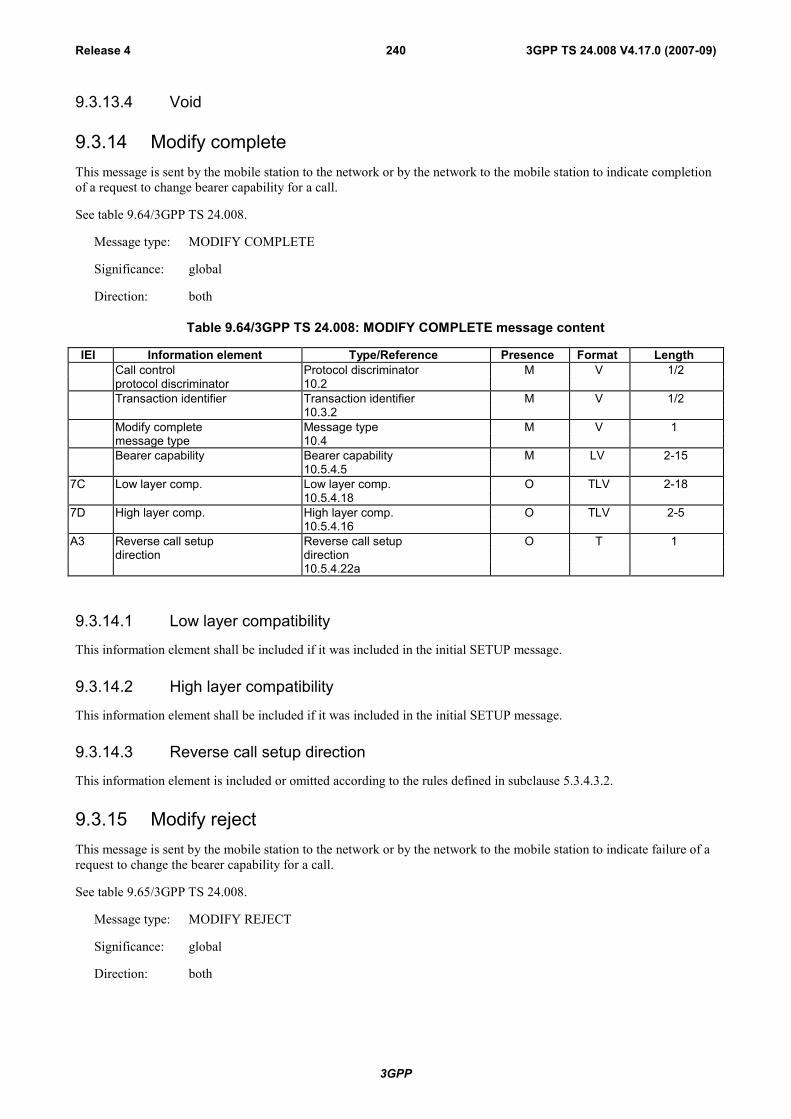
3GPP
3GPP TS 24.008 V4.17.0 (2007-09)Release 4 240
9.3.13.4 Void
9.3.14 Modify completeThis message is sent by the mobile station to the network or by the network to the mobile station to indicate completionof a request to change bearer capability for a call.
See table 9.64/3GPP TS 24.008.
Message type: MODIFY COMPLETE
Significance: global
Direction: both
Table 9.64/3GPP TS 24.008: MODIFY COMPLETE message content
IEI Information element Type/Reference Presence Format LengthCall control Protocol discriminator M V 1/2protocol discriminator 10.2Transaction identifier Transaction identifier M V 1/2
10.3.2Modify complete Message type M V 1message type 10.4Bearer capability Bearer capability M LV 2-15
10.5.4.57C Low layer comp. Low layer comp. O TLV 2-18
10.5.4.187D High layer comp. High layer comp. O TLV 2-5
10.5.4.16A3 Reverse call setup Reverse call setup O T 1
direction direction10.5.4.22a
9.3.14.1 Low layer compatibility
This information element shall be included if it was included in the initial SETUP message.
9.3.14.2 High layer compatibility
This information element shall be included if it was included in the initial SETUP message.
9.3.14.3 Reverse call setup direction
This information element is included or omitted according to the rules defined in subclause 5.3.4.3.2.
9.3.15 Modify rejectThis message is sent by the mobile station to the network or by the network to the mobile station to indicate failure of arequest to change the bearer capability for a call.
See table 9.65/3GPP TS 24.008.
Message type: MODIFY REJECT
Significance: global
Direction: both

3GPP
3GPP TS 24.008 V4.17.0 (2007-09)Release 4 241
Table 9.65/3GPP TS 24.008: MODIFY REJECT message content
IEI Information element Type/Reference Presence Format LengthCall control Protocol discriminator M V 1/2protocol discriminator 10.2Transaction identifier Transaction identifier M V 1/2
10.3.2Modify reject Message type M V 1message type 10.4Bearer capability Bearer capability M LV 2-15
10.5.4.5Cause Cause M LV 3-31
10.5.4.117C Low layer comp. Low layer comp. O TLV 2-18
10.5.4.187D High layer comp. High layer comp. O TLV 2-5
10.5.4.16
9.3.15.1 Low layer compatibility
This information element shall be included if it was included in the initial SETUP message.
9.3.15.2 High layer compatibility
This information element shall be included if it was included in the initial SETUP message.
9.3.16 NotifyThis message is sent either from the mobile station or from the network to indicate information pertaining to a call, suchas user suspended.
See table 9.66/3GPP TS 24.008.
Message type: NOTIFY
Significance: access
Direction: both
Table 9.66/3GPP TS 24.008: NOTIFY message content
IEI Information element Type/Reference Presence Format LengthCall control Protocol discriminator M V 1/2protocol discriminator 10.2Transaction identifier Transaction identifier M V 1/2
10.3.2Notify Message type M V 1message type 10.4Notification indicator Notification indicator M V 1
10.5.4.20
9.3.17 ProgressThis message is sent from the network to the mobile station to indicate the progress of a call in the event ofinterworking or in connection with the provision of in-band information/patterns.

3GPP
3GPP TS 24.008 V4.17.0 (2007-09)Release 4 242
See table 9.67/3GPP TS 24.008.
Message type: PROGRESS
Significance: global
Direction: network to mobile station
Table 9.67/3GPP TS 24.008: PROGRESS message content
IEI Information element Type/Reference Presence Format LengthCall control Protocol discriminator M V 1/2protocol discriminator 10.2Transaction identifier Transaction identifier M V 1/2
10.3.2Progress Message type M V 1message type 10.4Progress indicator Progress indicator M LV 3
10.5.4.217E User-user User-user O TLV 3-131
10.5.4.25
9.3.17.1 User-user
This information element is included when the PROGRESS message is sent by the network when the call has beencleared by the remote user before it reached the active state to indicate that the remote user wants to pass userinformation at call clearing time.
9.3.17a CC-Establishment $(CCBS)$A mobile station that does not support the "Network initiated MO call" option shall treat this message as a message withmessage type not defined for the PD.
This message is sent from the network to the mobile station to provide information on the call that the mobile stationshould attempt to establish.
See Table 9.67a/3GPP TS 24.008.
Message type: CC-ESTABLISHMENTSignificance: localDirection: network to mobile station
Table 9.67a/3GPP TS 24.008: CC-Establishment message content
IEI Information element Type/Reference Presence Format LengthCall control Protocol discriminator M V 1/2protocol discriminator 10.2Transaction identifier Transaction identifier M V 1/2
10.3.2CC-Establishment Message type M V 1message type 10.4Setup container Container M LV 3-n
10.5.4.22a
* From the 4th IE onwards the message is coded in the same way as the SETUP message in MS to networkdirection from the 4th IE onwards.

3GPP
3GPP TS 24.008 V4.17.0 (2007-09)Release 4 243
9.3.17a.1 Void
9.3.17a.2 Setup container
This information element contains the contents of a SETUP message (Mobile Station to Network).
9.3.17b CC-Establishment confirmed $(CCBS)$A Network that does not support the "Network initiated MO call" option shall treat this message as a message withmessage type not defined for the PD.
This message is sent by the mobile station to the network to indicate the requested channel characteristics for the callwhich may be initiated by the mobile station.
See Table 9.67b/3GPP TS 24.008.
Message type: CC-ESTABLISHMENT CONFIRMED
Significance: local
Direction: mobile station to network
Table 9.67b/3GPP TS 24.008: CC-ESTABLISHMENT CONFIRMED message content
IEI Information element Type/Reference Presence Format LengthCall control Protocol discriminator M V 1/2protocol discriminator 10.2Transaction identifier Transaction identifier M V 1/2
10.3.2CC-Establishmentconfirmed Message type M V 1message type 10.4
D- Repeat Indicator Repeat Indicator C TV 110.5.4.22
04 Bearer capability 1 Bearer capability M TLV 3-1010.5.4.5
04 Bearer capability 2 Bearer capability O TLV 3-1010.5.4.5
08 Cause Cause O TLV 4-3210.5.4.11
40 Supported Codecs Supported Codec List O TLV 5-n10.5.4.32
9.3.17b.1 Repeat indicator
The repeat indicator information element shall be included if bearer capability 1 information element and bearercapability 2 IE are both included in the message.
9.3.17b.2 Bearer capability 1 and bearer capability 2
If, in any subsequent SETUP message to be sent on this transaction the bearer capability 1 information element is to befollowed by the bearer capability 2 IE, then the bearer capability 2 IE shall be included in this message.
9.3.17b.3 Cause
This information element is included if the mobile station is compatible but the user is busy.
9.3.17b.4 Supported Codecs
This information element shall be included for speech calls, if the mobile station supports UMTS radio access.
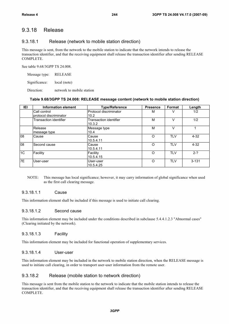
3GPP
3GPP TS 24.008 V4.17.0 (2007-09)Release 4 244
9.3.18 Release
9.3.18.1 Release (network to mobile station direction)
This message is sent, from the network to the mobile station to indicate that the network intends to release thetransaction identifier, and that the receiving equipment shall release the transaction identifier after sending RELEASECOMPLETE.
See table 9.68/3GPP TS 24.008.
Message type: RELEASE
Significance: local (note)
Direction: network to mobile station
Table 9.68/3GPP TS 24.008: RELEASE message content (network to mobile station direction)
IEI Information element Type/Reference Presence Format LengthCall control Protocol discriminator M V 1/2protocol discriminator 10.2Transaction identifier Transaction identifier M V 1/2
10.3.2Release Message type M V 1message type 10.4
08 Cause Cause O TLV 4-3210.5.4.11
08 Second cause Cause O TLV 4-3210.5.4.11
1C Facility Facility O TLV 2-?10.5.4.15
7E User-user User-user O TLV 3-13110.5.4.25
NOTE: This message has local significance; however, it may carry information of global significance when usedas the first call clearing message.
9.3.18.1.1 Cause
This information element shall be included if this message is used to initiate call clearing.
9.3.18.1.2 Second cause
This information element may be included under the conditions described in subclause 5.4.4.1.2.3 "Abnormal cases"(Clearing initiated by the network).
9.3.18.1.3 Facility
This information element may be included for functional operation of supplementary services.
9.3.18.1.4 User-user
This information element may be included in the network to mobile station direction, when the RELEASE message isused to initiate call clearing, in order to transport user-user information from the remote user.
9.3.18.2 Release (mobile station to network direction)
This message is sent from the mobile station to the network to indicate that the mobile station intends to release thetransaction identifier, and that the receiving equipment shall release the transaction identifier after sending RELEASECOMPLETE.

3GPP
3GPP TS 24.008 V4.17.0 (2007-09)Release 4 245
See table 9.68a/3GPP TS 24.008.
Message type: RELEASE
Significance: local (note)
Direction: mobile station to network direction
Table 9.68a/3GPP TS 24.008: RELEASE message content (mobile station to network direction)
IEI Information element Type/Reference Presence Format LengthCall control Protocol discriminator M V 1/2protocol discriminator 10.2Transaction identifier Transaction identifier M V 1/2
10.3.2Release Message type M V 1message type 10.4
08 Cause Cause O TLV 4-3210.5.4.11
08 Second cause Cause O TLV 4-3210.5.4.11
1C Facility Facility O TLV 2-?10.5.4.15
7E User-user User-user O TLV 3-13110.5.4.25
7F SS version SS version indicator O TLV 2-310.5.4.24
NOTE: This message has local significance; however, it may carry information of global significance when usedas the first call clearing message.
9.3.18.2.1 Cause
This information element shall be included if this message is used to initiate call clearing.
9.3.18.2.2 Second cause
This information element may be included under the conditions described in subclause 5.4.3.5 "Abnormal cases"(Clearing initiated by the mobile station).
9.3.18.2.3 Facility
This information element may be included for functional operation of supplementary services.
9.3.18.2.4 User-user
This information element is included when the RELEASE message is used to initiate call clearing and the mobilestation wants to pass user information to the remote user at call clearing time.
9.3.18.2.5 SS version
This information element shall not be included if the facility information element is not present in this message.
This information element shall be included or excluded as defined in 3GPP TS 24.010 [21]. This information elementshould not be transmitted unless explicitly required by 3GPP TS 24.010.
9.3.18a Recall $(CCBS)$A mobile station that does not support the "Network initiated MO call" option shall treat this message as a message withmessage type not defined for the PD.
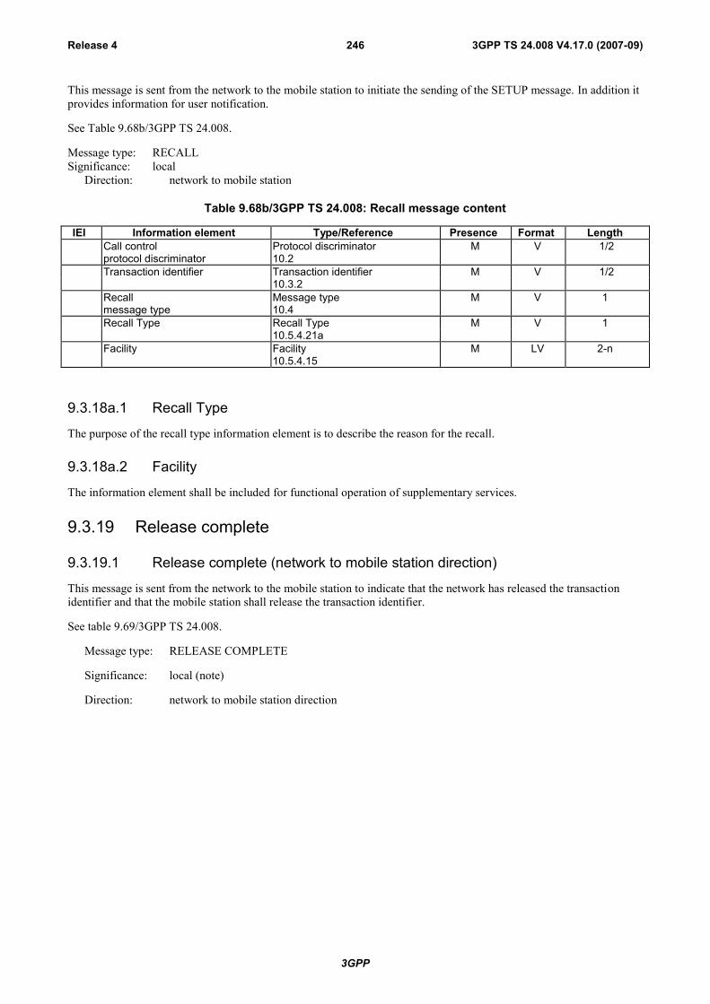
3GPP
3GPP TS 24.008 V4.17.0 (2007-09)Release 4 246
This message is sent from the network to the mobile station to initiate the sending of the SETUP message. In addition itprovides information for user notification.
See Table 9.68b/3GPP TS 24.008.
Message type: RECALLSignificance: local
Direction: network to mobile station
Table 9.68b/3GPP TS 24.008: Recall message content
IEI Information element Type/Reference Presence Format LengthCall control Protocol discriminator M V 1/2protocol discriminator 10.2Transaction identifier Transaction identifier M V 1/2
10.3.2Recall Message type M V 1message type 10.4Recall Type Recall Type M V 1
10.5.4.21aFacility Facility M LV 2-n
10.5.4.15
9.3.18a.1 Recall Type
The purpose of the recall type information element is to describe the reason for the recall.
9.3.18a.2 Facility
The information element shall be included for functional operation of supplementary services.
9.3.19 Release complete
9.3.19.1 Release complete (network to mobile station direction)
This message is sent from the network to the mobile station to indicate that the network has released the transactionidentifier and that the mobile station shall release the transaction identifier.
See table 9.69/3GPP TS 24.008.
Message type: RELEASE COMPLETE
Significance: local (note)
Direction: network to mobile station direction
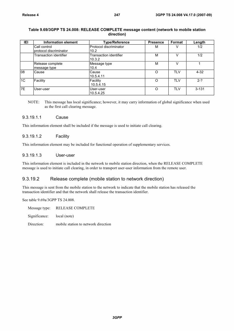
3GPP
3GPP TS 24.008 V4.17.0 (2007-09)Release 4 247
Table 9.69/3GPP TS 24.008: RELEASE COMPLETE message content (network to mobile stationdirection)
IEI Information element Type/Reference Presence Format LengthCall control Protocol discriminator M V 1/2protocol discriminator 10.2Transaction identifier Transaction identifier M V 1/2
10.3.2Release complete Message type M V 1message type 10.4
08 Cause Cause O TLV 4-3210.5.4.11
1C Facility Facility O TLV 2-? 10.5.4.15
7E User-user User-user O TLV 3-13110.5.4.25
NOTE: This message has local significance; however, it may carry information of global significance when usedas the first call clearing message.
9.3.19.1.1 Cause
This information element shall be included if the message is used to initiate call clearing.
9.3.19.1.2 Facility
This information element may be included for functional operation of supplementary services.
9.3.19.1.3 User-user
This information element is included in the network to mobile station direction, when the RELEASE COMPLETEmessage is used to initiate call clearing, in order to transport user-user information from the remote user.
9.3.19.2 Release complete (mobile station to network direction)
This message is sent from the mobile station to the network to indicate that the mobile station has released thetransaction identifier and that the network shall release the transaction identifier.
See table 9.69a/3GPP TS 24.008.
Message type: RELEASE COMPLETE
Significance: local (note)
Direction: mobile station to network direction

3GPP
3GPP TS 24.008 V4.17.0 (2007-09)Release 4 248
Table 9.69a/3GPP TS 24.008: RELEASE COMPLETE message content (mobile station to networkdirection)
IEI Information element Type/Reference Presence Format LengthCall control Protocol discriminator M V 1/2protocol discriminator 10.2Transaction identifier Transaction identifier M V 1/2
10.3.2Release complete Message type M V 1message type 10.4
08 Cause Cause O TLV 4-3210.5.4.11
1C Facility Facility O TLV 2-?10.5.4.15
7E User-user User-user O TLV 3-13110.5.4.25
7F SS version SS version indicator O TLV 2-310.5.4.24
NOTE: This message has local significance; however, it may carry information of global significance when usedas the first call clearing message.
9.3.19.2.1 Cause
This information element shall be included if the message is used to initiate call clearing.
9.3.19.2.2 Facility
This information element may be included for functional operation of supplementary services.
9.3.19.2.3 User-user
This information element is included in the mobile station to network direction when the RELEASE COMPLETEmessage is used to initiate call clearing and the mobile station wants to pass user information to the remote user at callclearing time.
9.3.19.2.4 SS version.
This information element shall not be included if the facility information element is not present in this message.
This information element shall be included or excluded as defined in 3GPP TS 24.010 [21]. This information elementshould not be transmitted unless explicitly required by 3GPP TS 24.010.
9.3.20 RetrieveThis message is sent by the mobile user to request the retrieval of a held call.
See table 9.69b/3GPP TS 24.008 for the content of the RETRIEVE message.
For the use of this message, see 3GPP TS 24.010 [21].

3GPP
3GPP TS 24.008 V4.17.0 (2007-09)Release 4 249
Message type: RETRIEVE
Significance: local
Direction: mobile station to network
Table 9.69b/3GPP TS 24.008: RETRIEVE message content
IEI Information element Type/Reference Presence Format LengthCall control Protocol discriminator M V 1/2protocol discriminator 10.2Transaction identifier Transaction identifier M V 1/2
10.3.2Retrieve Message type M V 1message type 10.4
9.3.21 Retrieve AcknowledgeThis message is sent by the network to indicate that the retrieve function has been successfully performed.
See table 9.69c/3GPP TS 24.008 for the content of the RETRIEVE ACKNOWLEDGE message.
For the use of this message, see 3GPP TS 24.010.
Message type: RETRIEVE ACKNOWLEDGE
Significance: local
Direction: network to mobile station
Table 9.69c/3GPP TS 24.008: RETRIEVE ACKNOWLEDGE message content
IEI Information element Type/Reference Presence Format LengthCall control Protocol discriminator M V 1/2protocol discriminator 10.2Transaction identifier Transaction identifier M V 1/2
10.3.2Retrieve Acknowledge Message type M V 1message type 10.4
9.3.22 Retrieve RejectThis message is sent by the network to indicate the inability to perform the requested retrieve function.
See table 9.69d/3GPP TS 24.008 for the content of the RETRIEVE REJECT message.
For the use of this message, see 3GPP TS 24.010.
Message type: RETRIEVE REJECT
Significance: local
Direction: network to mobile station

3GPP
3GPP TS 24.008 V4.17.0 (2007-09)Release 4 250
Table 9.69d/3GPP TS 24.008: RETRIEVE REJECT message content
IEI Information element Type/Reference Presence Format LengthCall control Protocol discriminator M V 1/2Protocol discriminator 10.2Transaction identifier Transaction identifier M V 1/2
10.3.2Retrieve Reject Message type M V 1Message type 10.4Cause 10.5.4.11 M LV 3-31
9.3.23 Setup
9.3.23.1 Setup (mobile terminated call establishment)
This message is sent by the network to the mobile station to initiate a mobile terminated call establishment.
See table 9.70/3GPP TS 24.008.
Message type: SETUP
Significance: global
Direction: network to mobile station

3GPP
3GPP TS 24.008 V4.17.0 (2007-09)Release 4 251
Table 9.70/3GPP TS 24.008: SETUP message content (network to mobile station direction)
IEI Information element Type/Reference Presence Format LengthCall control Protocol discriminator M V 1/2Protocol discriminator 10.2Transaction identifier Transaction identifier M V 1/2
10.3.2Setup Message type M V 1Message type 10.4
D- BC repeat indicator Repeat indicator C TV 110.5.4.22
04 Bearer capability 1 Bearer capability O TLV 3-1610.5.4.5
04 Bearer capability 2 Bearer capability O TLV 3-1610.5.4.5
1C Facility Facility O TLV 2-?10.5.4.15
1E Progress indicator Progress indicator O TLV 410.5.4.21
34 Signal Signal O TV 210.5.4.23
5C Calling party BCD Calling party BCD num. O TLV 3-14Number 10.5.4.9
5D Calling party sub- Calling party subaddr. O TLV 2-23Address 10.5.4.10
5E Called party BCD Called party BCD num. O TLV 3-19Number 10.5.4.7
6D Called party sub- Called party subaddr. O TLV 2-23Address 10.5.4.8
74 Redirecting party BCD number Redirecting party BCD num.10.5.4.21a
O TLV 3-19
75 Redirecting party sub-address Redirecting party subaddress.10.5.4.21b
O TLV 2-23
D- LLC repeat indicator Repeat indicator O TV 110.5.4.22
7C Low layer Low layer comp. O TLV 2-18Compatibility I 10.5.4.18
7C Low layer Low layer comp. C TLV 2-18Compatibility II 10.5.4.18
D- HLC repeat indicator Repeat indicator O TV 110.5.4.22
7D High layer High layer comp. O TLV 2-5Compatibility i 10.5.4.16
7D High layer High layer comp. C TLV 2-5Compatibility ii 10.5.4.16
7E User-user User-user O TLV 3-3510.5.4.25
8- Priority Priority Level O TV 110.5.1.11
19 Alert Alerting Pattern O TLV 310.5.4.26
2F Network Call Control Network Call Control cap. O TLV 3Capabilities 10.5.4.29
3A Cause of No CLI Cause of No CLI O TLV 310.5.4.30
9.3.23.1.1 BC repeat indicator
The BC repeat indicator information element is included if and only if bearer capability 1 information element andbearer capability 2 IE are both present in the message.
3GPP
3GPP TS 24.008 V4.17.0 (2007-09)Release 4 252
9.3.23.1.2 Bearer capability 1 and bearer capability 2
The bearer capability 1 information element may be omitted in the case where the mobile subscriber is allocated onlyone directory number for all services (ref.: 3GPP TS 29.007 [38]). The bearer capability 2 IE is missing at least if thebearer capability 1 IE is missing.
If the MSC wishes to indicate capability for an altenative call mode, which can be entered through fallback, this isindicated by adding a bearer capability information element (bearer capability) 2 element (see subclause 5.3.6).
9.3.23.1.3 Facility
This information element may be included for functional operation of supplementary services.
9.3.23.1.4 Progress indicator
This information element is included by the network
- in order to pass information about the call in progress e.g. in the event of interworking and/or
- to make the MS attach the user connection for speech.
9.3.23.1.4a Called party BCD number
For all bands except for PCS1900, the maximum length of this IE sent by the network shall be 13 octets
9.3.23.1.5 Called party subaddress
Included in the Network-to-mobile station direction if the calling user includes a called party subaddress informationelement in the SETUP message.
9.3.23.1.6 LLC repeat indicator
The LLC repeat indicator information element is included if and only if both following conditions hold:
- The BC repeat indicator IE is contained in the message.
- The low layer compatibility I IE is contained in the message.
If included, the LLC repeat indicator shall specify the same repeat indication as the BC repeat indicator IE.
9.3.23.1.7 Low layer compatibility I
Included in the network-to-mobile station direction if the calling user specified a low layer compatibility.
9.3.23.1.8 Low layer compatibility II
Included if and only if the LLC repeat indicator information element is contained in the message.
9.3.23.1.9 HLC repeat indicator
The HLC repeat indicator information element is included if and only both following conditions hold:
- The BC repeat indicator IE is contained in the message.
- The high layer compatibility i IE is contained in the message.
If included, the HLC repeat indicator shall specify the same repeat indication as the BC repeat indicator IE.
9.3.23.1.10 High layer compatibility i
Included in the network-to-mobile station direction if the calling user specified a high layer compatibility.
3GPP
3GPP TS 24.008 V4.17.0 (2007-09)Release 4 253
9.3.23.1.11 High layer compatibility ii
Included if and only if the HLC repeat indicator information element is contained in the message.
9.3.23.1.12 User-user
May be included in the network to called mobile station direction when the calling remote user included a user-userinformation element in the SETUP message.
9.3.23.1.13 Redirecting party BCD number
May be included in the network to called mobile station direction when the call has been redirected.
9.3.23.1.14 Redirecting party subaddress
May be included in the network to called mobile station direction when the calling remote user included a called partysubaddress in the SETUP message and the call has been redirected
9.3.23.1.15 Priority
May be included by the network to indicate the priority of the incoming call if eMLPP is used.
9.3.23.1.16 Alert $(Network Indication of Alerting in the MS)$
May be included by the network to give some indication about alerting (category or level). If supported in the MS, thisoptional indication is to be used by the MS as specified in 3GPP TS 22.101 [8].
9.3.23.1.17 Network Call Control Capabilities
This information shall be included by the network to indicate its call control capabilities if the network supportsmulticall.and there are no other ongoing calls to the MS.
9.3.23.1.18 Cause of No CLI
This IE may be included by the network as defined by 3GPP TS 24.081 [25].
When both Calling Party BCD number IE and Cause of No CLI IE are included in SETUP message then the Cause ofNo CLI IE provideds additional information on why the number digits are not present.
9.3.23.2 Setup (mobile originating call establishment)
This message is sent from the mobile station to the network to initiate a mobile originating call establishment.
See table 9.70a/3GPP TS 24.008.
Message type: SETUP
Significance: global
Direction: mobile station to network
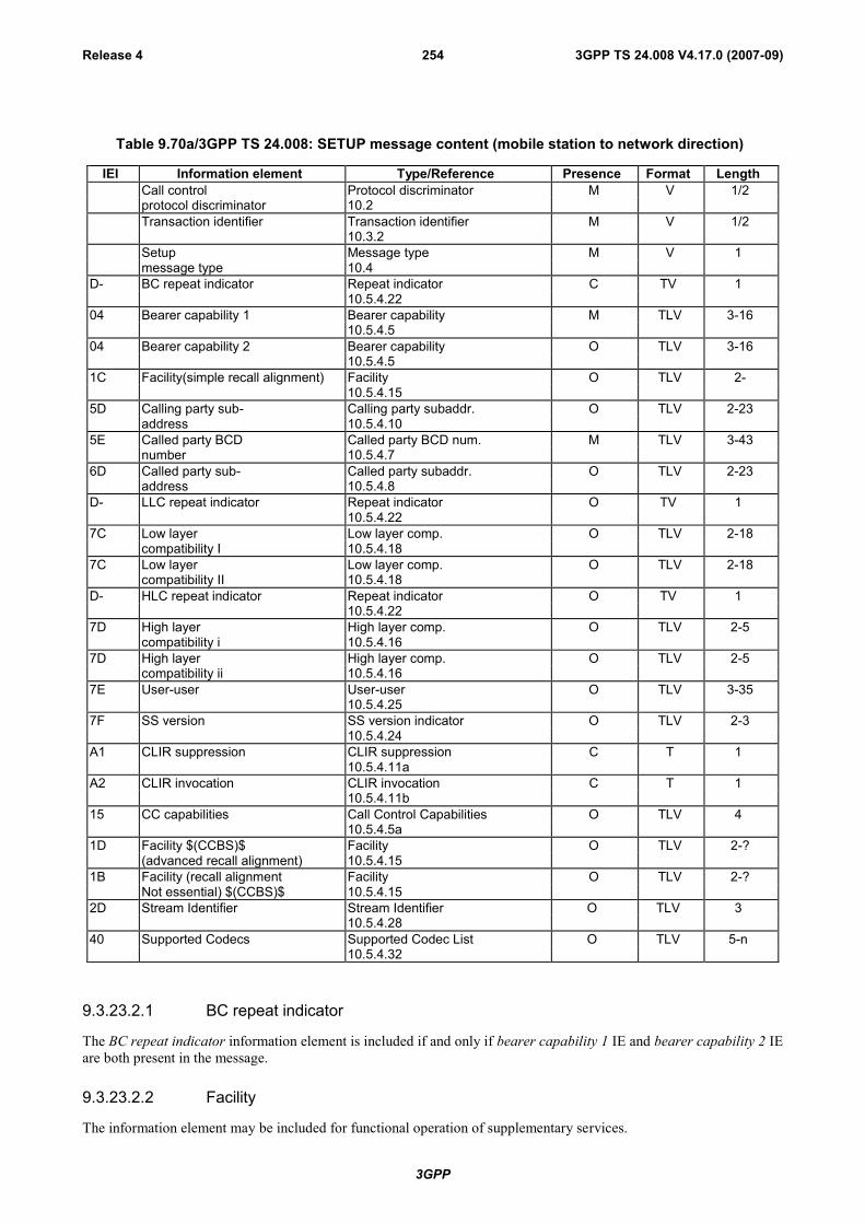
3GPP
3GPP TS 24.008 V4.17.0 (2007-09)Release 4 254
Table 9.70a/3GPP TS 24.008: SETUP message content (mobile station to network direction)
IEI Information element Type/Reference Presence Format LengthCall control Protocol discriminator M V 1/2protocol discriminator 10.2Transaction identifier Transaction identifier M V 1/2
10.3.2Setup Message type M V 1message type 10.4
D- BC repeat indicator Repeat indicator C TV 110.5.4.22
04 Bearer capability 1 Bearer capability M TLV 3-1610.5.4.5
04 Bearer capability 2 Bearer capability O TLV 3-1610.5.4.5
1C Facility(simple recall alignment) Facility O TLV 2-10.5.4.15
5D Calling party sub- Calling party subaddr. O TLV 2-23address 10.5.4.10
5E Called party BCD Called party BCD num. M TLV 3-43number 10.5.4.7
6D Called party sub- Called party subaddr. O TLV 2-23address 10.5.4.8
D- LLC repeat indicator Repeat indicator O TV 110.5.4.22
7C Low layer Low layer comp. O TLV 2-18compatibility I 10.5.4.18
7C Low layer Low layer comp. O TLV 2-18compatibility II 10.5.4.18
D- HLC repeat indicator Repeat indicator O TV 110.5.4.22
7D High layer High layer comp. O TLV 2-5compatibility i 10.5.4.16
7D High layer High layer comp. O TLV 2-5compatibility ii 10.5.4.16
7E User-user User-user O TLV 3-3510.5.4.25
7F SS version SS version indicator O TLV 2-310.5.4.24
A1 CLIR suppression CLIR suppression C T 110.5.4.11a
A2 CLIR invocation CLIR invocation C T 110.5.4.11b
15 CC capabilities Call Control Capabilities O TLV 410.5.4.5a
1D Facility $(CCBS)$ Facility O TLV 2-?(advanced recall alignment) 10.5.4.15
1B Facility (recall alignment Facility O TLV 2-?Not essential) $(CCBS)$ 10.5.4.15
2D Stream Identifier Stream Identifier O TLV 310.5.4.28
40 Supported Codecs Supported Codec List O TLV 5-n10.5.4.32
9.3.23.2.1 BC repeat indicator
The BC repeat indicator information element is included if and only if bearer capability 1 IE and bearer capability 2 IEare both present in the message.
9.3.23.2.2 Facility
The information element may be included for functional operation of supplementary services.

3GPP
3GPP TS 24.008 V4.17.0 (2007-09)Release 4 255
Three different codings of this IE exist, for further details see 3GPP TS 24.010.
9.3.23.2.3 LLC repeat indicator
The LLC repeat indicator information element is included if and only if both following conditions hold:
- The BC repeat indicator IE is contained in the message.
- The low layer compatibility I IE is contained in the message.
If included, the LLC repeat indicator shall specify the same repeat indication as the BC repeat indicator IE.
9.3.23.2.4 Low layer compatibility I
The information element is included in the MS-to-network direction when the calling MS wants to pass low layercompatibility information to the called user.
9.3.23.2.5 Low layer compatibility II
Included if and only if the LLC repeat indicator information element is contained in the message.
9.3.23.2.6 HLC repeat indicator
The HLC repeat indicator information element is included if and only if both following conditions hold:
- The BC repeat indicator IE is contained in the message.
- The high layer compatibility i IE is contained in the message.
If included, the HLC repeat indicator shall specify the same repeat indication as the BC repeat indicator IE.
9.3.23.2.7 High layer compatibility i
The information element is included when the calling MS wants to pass high layer compatibility information to thecalled user.
9.3.23.2.8 High layer compatibility ii
Included if and only if the HLC repeat indicator information element is contained in the message.
9.3.23.2.9 User-user
The information element is included in the calling mobile station to network direction when the calling mobile stationwants to pass user information to the called remote user.
9.3.23.2.10 SS version
This information element shall not be included if the facility information element is not present in this message.
This information element shall be included or excluded as defined in 3GPP TS 24.010 [21]. This information elementshould not be transmitted unless explicitly required by 3GPP TS 24.010.
9.3.23.2.11 CLIR suppression
The information element may be included by the MS (see 3GPP TS 24.081 [25]). If this information element is includedthe CLIR invocation IE shall not be included.
9.3.23.2.12 CLIR invocation
The information element may be included by the MS (see 3GPP TS 24.081). If this information element is included theCLIR suppression IE shall not be included.

3GPP
3GPP TS 24.008 V4.17.0 (2007-09)Release 4 256
9.3.23.2.13 CC Capabilities
This information element may be included by the mobile station to indicate its call control capabilities.
9.3.23.2.14 Stream Identifier
This information element shall be included by the mobile station supporting multicall.
9.3.23.2.15 Bearer capability 1 and bearer capability 2
If the mobile station wishes to indicate capability for an altenative call mode, which can be entered throughfallback, thisis indicated by adding a bearer capability information element (bearer capability) 2 element (see subclause 5.3.6).
9.3.23.2.16 Supported Codecs
This information element shall be included for speech calls, if the mobile station supports UMTS radio access.
9.3.23a Start CC $(CCBS)$A Network that does not support the "Network initiated MO call" option shall treat this message as a message withmessage type not defined for the PD.
This message is sent by the mobile station to the network to open a Call Control transaction which the network hasrequested the mobile station to open.
See Table 9.70b/3GPP TS 24.008.
Message type: START CCSignificance: localDirection: mobile station to network
Table 9.70b/3GPP TS 24.008: START CC message content
IEI Information element Type/Reference Presence Format LengthCall control Protocol discriminator M V 1/2Protocol discriminator 10.2Transaction identifier Transaction identifier M V 1/2
10.3.2Start CC Message type M V 1message type 10.4
15 CC Capabilities Call Control Capabilities O TLV 410.5.4.5a
9.3.23a.1 CC Capabilities
This information element may be included by the mobile station to indicate its call control capabilities
9.3.24 Start DTMFThis message is sent by the mobile station to the network and contains the digit the network should reconvert back intoa DTMF tone which is then applied towards the remote user.
See table 9.71/3GPP TS 24.008.
Message type: START DTMF
Significance: local
Direction: mobile station to network

3GPP
3GPP TS 24.008 V4.17.0 (2007-09)Release 4 257
Table 9.71/3GPP TS 24.008: START DTMF message content
IEI Information element Type/Reference Presence Format LengthCall control Protocol discriminator M V 1/2protocol discriminator 10.2Transaction identifier Transaction identifier M V 1/2
10.3.2Start DTMF Message type M V 1message type 10.4
2C Keypad facility Keypad facility M TV 210.5.4.17
9.3.25 Start DTMF AcknowledgeThis message is sent by the network to the mobile station to indicate the successful initiation of the action requested bythe START DTMF message (conversion of the digit contained in this message into a DTMF tone).
See table 9.72/3GPP TS 24.008.
Message type: START DTMF ACKNOWLEDGE
Significance: local
Direction: network to mobile station
Table 9.72/3GPP TS 24.008: START DTMF ACKNOWLEDGE message content
IEI Information element Type/Reference Presence Format LengthCall control Protocol discriminator M V 1/2protocol discriminator 10.2Transaction identifier Transaction identifier M V 1/2
10.3.2Start DTMF acknowledge Message type M V 1message type 10.4
2C Keypad facility Keypad facility M TV 210.5.4.17
9.3.25.1 Keypad facility
This information element contains the digit corresponding to the DTMF tone that the network applies towards theremote user.
9.3.26 Start DTMF rejectThis message is sent by the network to the mobile station, if the network can not accept the START DTMF message.
See table 9.73/3GPP TS 24.008.
Message type: START DTMF REJECT
Significance: local
Direction: network to mobile station

3GPP
3GPP TS 24.008 V4.17.0 (2007-09)Release 4 258
Table 9.73/3GPP TS 24.008: START DTMF REJECT message content
IEI Information element Type/Reference Presence Format LengthCall control Protocol discriminator M V 1/2protocol discriminator 10.2Transaction identifier Transaction identifier M V 1/2
10.3.2Start DTMF reject Message type M V 1message type 10.4Cause Cause M LV 3-31
10.5.4.11
9.3.27 StatusThis message is sent by the mobile station or the network at any time during a call to report certain error conditionslisted in clause 8. It shall also be sent in response to a STATUS ENQUIRY message.
See table 9.74/3GPP TS 24.008.
Message type: STATUS
Significance: local
Direction: both
Table 9.74/3GPP TS 24.008: STATUS message content
IEI Information element Type/Reference Presence Format LengthCall control Protocol discriminator M V 1/2protocol discriminator 10.2Transaction identifier Transaction identifier M V 1/2
10.3.2Status Message type M V 1message type 10.4Cause Cause M LV 3-31
10.5.4.11Call state Call state M V 1
10.5.4.624 Auxiliary states Auxiliary states O TLV 3
10.5.4.4
9.3.27.1 Auxiliary states
The information element is included if and only if the call state is "active" or "mobile originating modify" and anyauxiliary state is different from "idle". For the definition of the auxiliary states see 3GPP TS 24.083 and 3GPP TS24.084
9.3.28 Status enquiryThis message is sent by the mobile station or the network at any time to solicit a STATUS message from the peer layer3 entity. Sending of STATUS message in response to a STATUS ENQUIRY message is mandatory.
See table 9.75/3GPP TS 24.008.
Message type: STATUS ENQUIRY
Significance: local
Direction: both
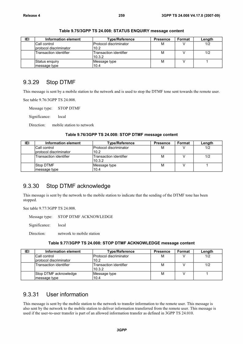
3GPP
3GPP TS 24.008 V4.17.0 (2007-09)Release 4 259
Table 9.75/3GPP TS 24.008: STATUS ENQUIRY message content
IEI Information element Type/Reference Presence Format LengthCall control Protocol discriminator M V 1/2protocol discriminator 10.2Transaction identifier Transaction identifier M V 1/2
10.3.2Status enquiry Message type M V 1message type 10.4
9.3.29 Stop DTMFThis message is sent by a mobile station to the network and is used to stop the DTMF tone sent towards the remote user.
See table 9.76/3GPP TS 24.008.
Message type: STOP DTMF
Significance: local
Direction: mobile station to network
Table 9.76/3GPP TS 24.008: STOP DTMF message content
IEI Information element Type/Reference Presence Format LengthCall control Protocol discriminator M V 1/2protocol discriminator 10.2Transaction identifier Transaction identifier M V 1/2
10.3.2Stop DTMF Message type M V 1message type 10.4
9.3.30 Stop DTMF acknowledgeThis message is sent by the network to the mobile station to indicate that the sending of the DTMF tone has beenstopped.
See table 9.77/3GPP TS 24.008.
Message type: STOP DTMF ACKNOWLEDGE
Significance: local
Direction: network to mobile station
Table 9.77/3GPP TS 24.008: STOP DTMF ACKNOWLEDGE message content
IEI Information element Type/Reference Presence Format LengthCall control Protocol discriminator M V 1/2protocol discriminator 10.2Transaction identifier Transaction identifier M V 1/2
10.3.2Stop DTMF acknowledge Message type M V 1message type 10.4
9.3.31 User informationThis message is sent by the mobile station to the network to transfer information to the remote user. This message isalso sent by the network to the mobile station to deliver information transferred from the remote user. This message isused if the user-to-user transfer is part of an allowed information transfer as defined in 3GPP TS 24.010.
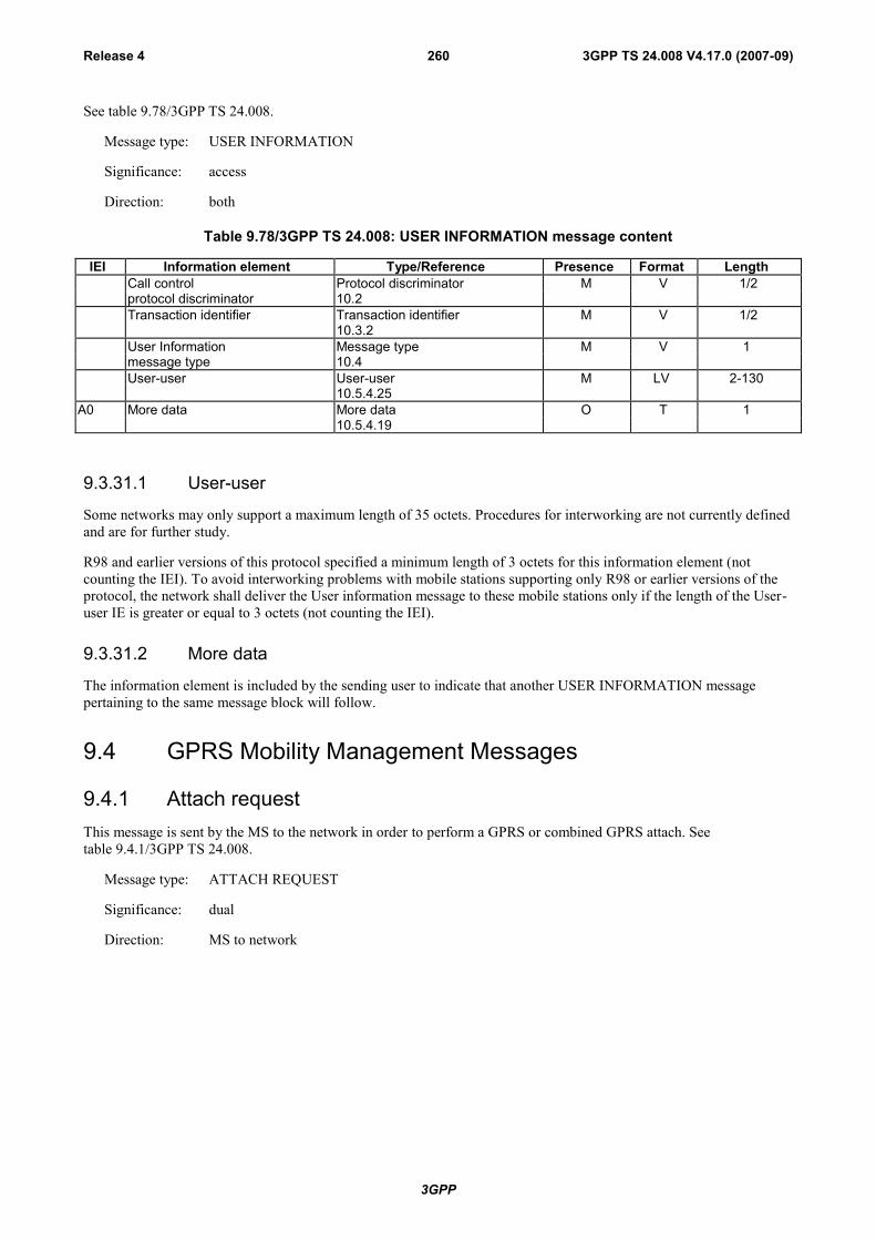
3GPP
3GPP TS 24.008 V4.17.0 (2007-09)Release 4 260
See table 9.78/3GPP TS 24.008.
Message type: USER INFORMATION
Significance: access
Direction: both
Table 9.78/3GPP TS 24.008: USER INFORMATION message content
IEI Information element Type/Reference Presence Format LengthCall control Protocol discriminator M V 1/2protocol discriminator 10.2Transaction identifier Transaction identifier M V 1/2
10.3.2User Information Message type M V 1message type 10.4User-user User-user M LV 2-130
10.5.4.25A0 More data More data O T 1
10.5.4.19
9.3.31.1 User-user
Some networks may only support a maximum length of 35 octets. Procedures for interworking are not currently definedand are for further study.
R98 and earlier versions of this protocol specified a minimum length of 3 octets for this information element (notcounting the IEI). To avoid interworking problems with mobile stations supporting only R98 or earlier versions of theprotocol, the network shall deliver the User information message to these mobile stations only if the length of the User-user IE is greater or equal to 3 octets (not counting the IEI).
9.3.31.2 More data
The information element is included by the sending user to indicate that another USER INFORMATION messagepertaining to the same message block will follow.
9.4 GPRS Mobility Management Messages
9.4.1 Attach requestThis message is sent by the MS to the network in order to perform a GPRS or combined GPRS attach. Seetable 9.4.1/3GPP TS 24.008.
Message type: ATTACH REQUEST
Significance: dual
Direction: MS to network

3GPP
3GPP TS 24.008 V4.17.0 (2007-09)Release 4 261
Table 9.4.1/3GPP TS 24.008: ATTACH REQUEST message content
IEI Information Element Type/Reference Presence Format LengthProtocol discriminator Protocol discriminator
10.2M V 1/2
Skip indicator Skip indicator10.3.1
M V ½
Attach request message identity Message type10.4
M V 1
MS network capability MS network capability10.5.5.12
M LV 3-9
Attach type Attach type10.5.5.2
M V ½
GPRS ciphering key sequencenumber
Ciphering key sequence number10.5.1.2
M V ½
DRX parameter DRX parameter10.5.5.6
M V 2
P-TMSI or IMSI Mobile identity10.5.1.4
M LV 6 - 9
Old routing area identification Routing area identification10.5.5.15
M V 6
MS Radio Access capability MS Radio Access capability10.5.5.12a
M LV 6 - 52
19 Old P-TMSI signature P-TMSI signature10.5.5.8
O TV 4
17 Requested READY timervalue
GPRS Timer10.5.7.3
O TV 2
9- TMSI status TMSI status10.5.5.4
O TV 1
9.4.1.1 Old P-TMSI signature
This IE is included if a valid P-TMSI and P-TMSI signature are stored in the MS.
9.4.1.2 Requested READY timer value
This IE may be included if the MS wants to indicate a preferred value for the READY timer.
9.4.1.3 TMSI status
This IE shall be included if the MS performs a combined GPRS attach and no valid TMSI is available.
9.4.2 Attach acceptThis message is sent by the network to the MS to indicate that the corresponding attach request has been accepted. Seetable 9.4.2/3GPP TS 24.008.
Message type: ATTACH ACCEPT
Significance: dual
Direction: network to MS

3GPP
3GPP TS 24.008 V4.17.0 (2007-09)Release 4 262
Table 9.4.2/3GPP TS 24.008: ATTACH ACCEPT message content
IEI Information Element Type/Reference Presence Format LengthProtocol discriminator Protocol discriminator
10.2M V 1/2
Skip indicator Skip indicator10.3.1
M V 1/2
Attach accept message identity Message type10.4
M V 1
Attach result Attach result10.5.5.1
M V 1/2
Force to standby Force to standby10.5.5.7
M V 1/2
Periodic RA update timer GPRS Timer10.5.7.3
M V 1
Radio priority for SMS Radio priority10.5.7.2
M V 1/2
Spare half octet Spare half octet10.5.1.8
M V 1/2
Routing area identification Routing area identification10.5.5.15
M V 6
19 P-TMSI signature P-TMSI signature10.5.5.8
O TV 4
17 Negotiated READY timervalue
GPRS Timer10.5.7.3
O TV 2
18 Allocated P-TMSI Mobile identity10.5.1.4
O TLV 7
23 MS identity Mobile identity10.5.1.4
O TLV 7-10
25 GMM cause GMM cause10.5.5.14
O TV 2
2A T3302 value GPRS Timer 210.5.7.4
O TLV 3
8C Cell Notification Cell Notification10.5.5.21
O T 1
4A Equivalent PLMNs PLMN List10.5.1.13
O TLV 5-17
B- Network feature support Network feature support10.5.5.23
O TV 1
9.4.2.1 P-TMSI signature
This IE may be included to assign an identity to the MS's GMM context.
9.4.2.2 Negotiated READY timer
This IE may be included to indicate a value for the READY timer.
9.4.2.3 Allocated P-TMSI
This IE may be included to assign a P-TMSI to an MS in case of a GPRS or combined GPRS attach.
9.4.2.4 MS identity
This IE may be included to assign or unassign a TMSI to an MS in case of a combined GPRS attach.
9.4.2.5 GMM cause
This IE shall be included when IMSI attach for non-GPRS services was not successful during a combined GPRS attachprocedure.
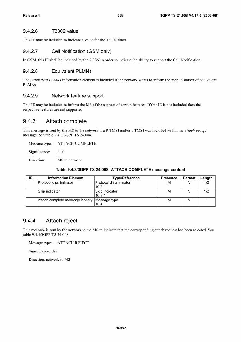
3GPP
3GPP TS 24.008 V4.17.0 (2007-09)Release 4 263
9.4.2.6 T3302 value
This IE may be included to indicate a value for the T3302 timer.
9.4.2.7 Cell Notification (GSM only)
In GSM, this IE shall be included by the SGSN in order to indicate the ability to support the Cell Notification.
9.4.2.8 Equivalent PLMNs
The Equivalent PLMNs information element is included if the network wants to inform the mobile station of equivalentPLMNs.
9.4.2.9 Network feature support
This IE may be included to inform the MS of the support of certain features. If this IE is not included then therespective features are not supported.
9.4.3 Attach completeThis message is sent by the MS to the network if a P-TMSI and/or a TMSI was included within the attach acceptmessage. See table 9.4.3/3GPP TS 24.008.
Message type: ATTACH COMPLETE
Significance: dual
Direction: MS to network
Table 9.4.3/3GPP TS 24.008: ATTACH COMPLETE message content
IEI Information Element Type/Reference Presence Format LengthProtocol discriminator Protocol discriminator
10.2M V 1/2
Skip indicator Skip indicator10.3.1
M V 1/2
Attach complete message identity Message type10.4
M V 1
9.4.4 Attach rejectThis message is sent by the network to the MS to indicate that the corresponding attach request has been rejected. Seetable 9.4.4/3GPP TS 24.008.
Message type: ATTACH REJECT
Significance: dual
Direction: network to MS

3GPP
3GPP TS 24.008 V4.17.0 (2007-09)Release 4 264
Table 9.4.4/3GPP TS 24.008: ATTACH REJECT message content
IEI Information Element Type/Reference Presence Format LengthProtocol discriminator Protocol discriminator
10.2M V 1/2
Skip indicator Skip indicator10.3.1
M V 1/2
Attach reject message identity Message type10.4
M V 1
GMM cause GMM cause10.5.5.14
M V 1
2A T3302 value GPRS Timer 210.5.7.4
O TLV 3
9.4.4.1 T3302 value
This IE may be included to indicate a value for the T3302 timer.
9.4.5 Detach request
9.4.5.1 Detach request (mobile terminated detach)
This message is sent by the network to request the release of a GMM context. See table 9.4.5.1/3GPP TS 24.008.
Message type: DETACH REQUEST
Significance: dual
Direction: network to MS
Table 9.4.5.1/3GPP TS 24.008:DETACH REQUEST message content
IEI Information Element Type/Reference Presence Format LengthProtocol discriminator Protocol discriminator
10.2M V 1/2
Skip indicator Skip indicator10.3.1
M V 1/2
Detach request message identity Message type10.4
M V 1
Detach type Detach type10.5.5.5
M V 1/2
Force to standby Force to standby10.5.5.7
M V 1/2
25 GMM cause GMM cause10.5.5.14
O TV 2
9.4.5.1.1 GMM cause
This IE shall be included in case the detach reason has to be indicated to the MS, e.g. due to a failed IMEI check.
9.4.5.2 Detach request (mobile originating detach)
This message is sent by the MS to request the release of a GMM context. See table 9.4.5.2/3GPP TS 24.008.
Message type: DETACH REQUEST
Significance: dual
Direction: MS to network
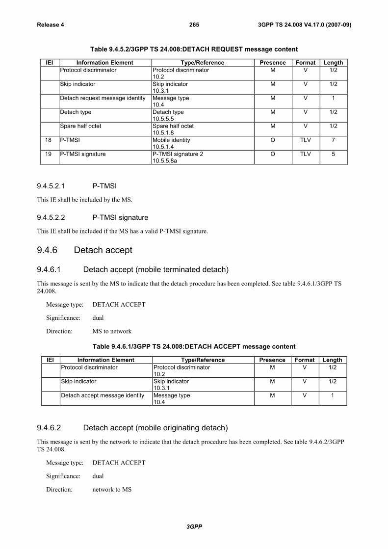
3GPP
3GPP TS 24.008 V4.17.0 (2007-09)Release 4 265
Table 9.4.5.2/3GPP TS 24.008:DETACH REQUEST message content
IEI Information Element Type/Reference Presence Format LengthProtocol discriminator Protocol discriminator
10.2M V 1/2
Skip indicator Skip indicator10.3.1
M V 1/2
Detach request message identity Message type10.4
M V 1
Detach type Detach type10.5.5.5
M V 1/2
Spare half octet Spare half octet10.5.1.8
M V 1/2
18 P-TMSI Mobile identity10.5.1.4
O TLV 7
19 P-TMSI signature P-TMSI signature 210.5.5.8a
O TLV 5
9.4.5.2.1 P-TMSI
This IE shall be included by the MS.
9.4.5.2.2 P-TMSI signature
This IE shall be included if the MS has a valid P-TMSI signature.
9.4.6 Detach accept
9.4.6.1 Detach accept (mobile terminated detach)
This message is sent by the MS to indicate that the detach procedure has been completed. See table 9.4.6.1/3GPP TS24.008.
Message type: DETACH ACCEPT
Significance: dual
Direction: MS to network
Table 9.4.6.1/3GPP TS 24.008:DETACH ACCEPT message content
IEI Information Element Type/Reference Presence Format LengthProtocol discriminator Protocol discriminator
10.2M V 1/2
Skip indicator Skip indicator10.3.1
M V 1/2
Detach accept message identity Message type10.4
M V 1
9.4.6.2 Detach accept (mobile originating detach)
This message is sent by the network to indicate that the detach procedure has been completed. See table 9.4.6.2/3GPPTS 24.008.
Message type: DETACH ACCEPT
Significance: dual
Direction: network to MS
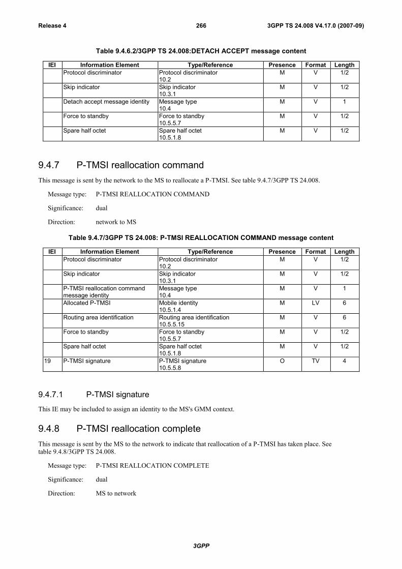
3GPP
3GPP TS 24.008 V4.17.0 (2007-09)Release 4 266
Table 9.4.6.2/3GPP TS 24.008:DETACH ACCEPT message content
IEI Information Element Type/Reference Presence Format LengthProtocol discriminator Protocol discriminator
10.2M V 1/2
Skip indicator Skip indicator10.3.1
M V 1/2
Detach accept message identity Message type10.4
M V 1
Force to standby Force to standby10.5.5.7
M V 1/2
Spare half octet Spare half octet10.5.1.8
M V 1/2
9.4.7 P-TMSI reallocation commandThis message is sent by the network to the MS to reallocate a P-TMSI. See table 9.4.7/3GPP TS 24.008.
Message type: P-TMSI REALLOCATION COMMAND
Significance: dual
Direction: network to MS
Table 9.4.7/3GPP TS 24.008: P-TMSI REALLOCATION COMMAND message content
IEI Information Element Type/Reference Presence Format LengthProtocol discriminator Protocol discriminator
10.2M V 1/2
Skip indicator Skip indicator10.3.1
M V 1/2
P-TMSI reallocation commandmessage identity
Message type10.4
M V 1
Allocated P-TMSI Mobile identity10.5.1.4
M LV 6
Routing area identification Routing area identification10.5.5.15
M V 6
Force to standby Force to standby10.5.5.7
M V 1/2
Spare half octet Spare half octet10.5.1.8
M V 1/2
19 P-TMSI signature P-TMSI signature10.5.5.8
O TV 4
9.4.7.1 P-TMSI signature
This IE may be included to assign an identity to the MS's GMM context.
9.4.8 P-TMSI reallocation completeThis message is sent by the MS to the network to indicate that reallocation of a P-TMSI has taken place. Seetable 9.4.8/3GPP TS 24.008.
Message type: P-TMSI REALLOCATION COMPLETE
Significance: dual
Direction: MS to network

3GPP
3GPP TS 24.008 V4.17.0 (2007-09)Release 4 267
Table 9.4.8/3GPP TS 24.008: P-TMSI REALLOCATION COMPLETE message content
IEI Information Element Type/Reference Presence Format LengthProtocol discriminator Protocol discriminator
10.2M V 1/2
Skip indicator Skip indicator10.3.1
M V 1/2
P-TMSI reallocation completemessage identity
Message type10.4
M V 1
9.4.9 Authentication and ciphering requestThis message is sent by the network to the MS to initiate authentication of the MS identity. Additionally, the cipheringmode is set, indicating whether ciphering will be performed or not. See table 9.4.9/3GPP TS 24.008.
Message type: AUTHENTICATION AND CIPHERING REQUEST
Significance: dual
Direction: network to MS
Table 9.4.9/GSM 24.008: AUTHENTICATION AND CIPHERING REQUEST message content
IEI Information Element Type/Reference Presence Format LengthProtocol discriminator Protocol discriminator
10.2M V 1/2
Skip indicator Skip indicator10.3.1
M V 1/2
Authentication and cipheringrequest message identity
Message type10.4
M V 1
Ciphering algorithm Ciphering algorithm10.5.5.3
M V 1/2
IMEISV request IMEISV request10.5.5.10
M V 1/2
Force to standby Force to standby10.5.5.7
M V 1/2
A&C reference number A&C reference number10.5.5.19
M V 1/2
21 Authentication parameter RAND Authentication parameter RAND10.5.3.1
O TV 17
8- GPRS ciphering key sequencenumber
Ciphering key sequence number10.5.1.2
C TV 1
28 Authentication parameterAUTN
Authentication parameter AUTN10.5.3.1.1
O TLV 18
9.4.9.1 Authentication Parameter RAND
This IE shall only be included if authentication shall be performed.
9.4.9.2 GPRS ciphering key sequence number
This IE is included if and only if the Authentication parameter RAND is contained in the message.
9.4.9.3 Authentication Parameter AUTN
This IE shall be present if and only if the authentication challenge is a UMTS authentication challenge.The presence orabsence of this IE defines- in the case of its absence- a GSM authentication challenge or- in the case of its presence- aUMTS authentication challenge.
The MS shall ignore the IE if it does not support UMTS authentication algorithm.

3GPP
3GPP TS 24.008 V4.17.0 (2007-09)Release 4 268
In UMTS, the MS shall reject the AUTHENTICATION & CIPHERING REQUEST message as specified insubclause 4.7.7.5.1 if this IE is not present and the MS supports UMTS authentication algorithm.
9.4.10 Authentication and ciphering responseThis message is sent by the MS to the network in response to an Authentication and ciphering request message. Seetable 9.4.10/3GPP TS 24.008.
Message type: AUTHENTICATION AND CIPHERING RESPONSE
Significance: dual
Direction: MS to network
Table 9.4.10/3GPP TS 24.008: AUTHENTICATION AND CIPHERING RESPONSE message content
IEI Information Element Type/Reference Presence Format LengthProtocol discriminator Protocol discriminator
10.2M V 1/2
Skip indicator Skip indicator10.3.1
M V 1/2
Authentication and cipheringresponse message identity
GPRS message type10.4
M V 1
A&C reference number A&C reference number10.5.5.19
M V 1/2
Spare half octet Spare half octet10.5.1.8
M V 1/2
22 Authentication parameterResponse
Authentication Response parameter10.5.3.2
O TV 5
23 IMEISV Mobile identity10.5.1.4
O TLV 11
29 Authentication Responseparameter (extension)
Authentication Response parameter10.5.3.2.1
O TLV 3-14
9.4.10.1 Authentication Response Parameter
This IE is included if authentication was requested within the corresponding authentication and ciphering requestmessage. This IE contains the SRES, if the authentication challenge was for GSM or the RES (all or just the 4 mostsignificant octets of) if it is a UMTS authentication challenge (see also subclause 9.4.10.2)
9.4.10.2 IMEISV
This IE is included if requested within the corresponding authentication and ciphering request message.
9.4.10.3 Authentication Response Parameter (extension)
This IE shall be included if and only if the authentication challenge was a UMTS authentication challenge and the RESparameter is greater than 4 octets in length. It shall contain the least significant remaining bits of the RES (the four mostsignificant octets shall be sent in the Authentication Response Parameter IE (see subclause 9.2.3.1))
This IE shall not be included if MS does not support UMTS authentication algorithm.
9.4.10a Authentication and Ciphering FailureThis message is sent by the mobile station to the network to indicate that authentication of the network has failed. Seetable 9.4.10a/3GPP TS 24.008.
Message type: AUTHENTICATION AND CIPHERING FAILURE
Significance: dual
Direction: mobile station to network
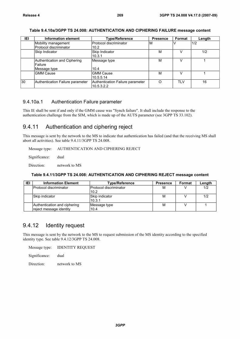
3GPP
3GPP TS 24.008 V4.17.0 (2007-09)Release 4 269
Table 9.4.10a/3GPP TS 24.008: AUTHENTICATION AND CIPHERING FAILURE message content
IEI Information element Type/Reference Presence Format LengthMobility management Protocol discriminator M V 1/2Protocol discriminator 10.2Skip Indicator Skip Indicator M V 1/2
10.3.1Authentication and CipheringFailure
Message type M V 1
Message type 10.4GMM Cause GMM Cause
10.5.5.14M V 1
30 Authentication Failure parameter Authentication Failure parameter O TLV 1610.5.3.2.2
9.4.10a.1 Authentication Failure parameter
This IE shall be sent if and only if the GMM cause was "Synch failure". It shall include the response to theauthentication challenge from the SIM, which is made up of the AUTS parameter (see 3GPP TS 33.102).
9.4.11 Authentication and ciphering rejectThis message is sent by the network to the MS to indicate that authentication has failed (and that the receiving MS shallabort all activities). See table 9.4.11/3GPP TS 24.008.
Message type: AUTHENTICATION AND CIPHERING REJECT
Significance: dual
Direction: network to MS
Table 9.4.11/3GPP TS 24.008: AUTHENTICATION AND CIPHERING REJECT message content
IEI Information Element Type/Reference Presence Format LengthProtocol discriminator Protocol discriminator
10.2M V 1/2
Skip indicator Skip indicator10.3.1
M V 1/2
Authentication and cipheringreject message identity
Message type10.4
M V 1
9.4.12 Identity requestThis message is sent by the network to the MS to request submission of the MS identity according to the specifiedidentity type. See table 9.4.12/3GPP TS 24.008.
Message type: IDENTITY REQUEST
Significance: dual
Direction: network to MS
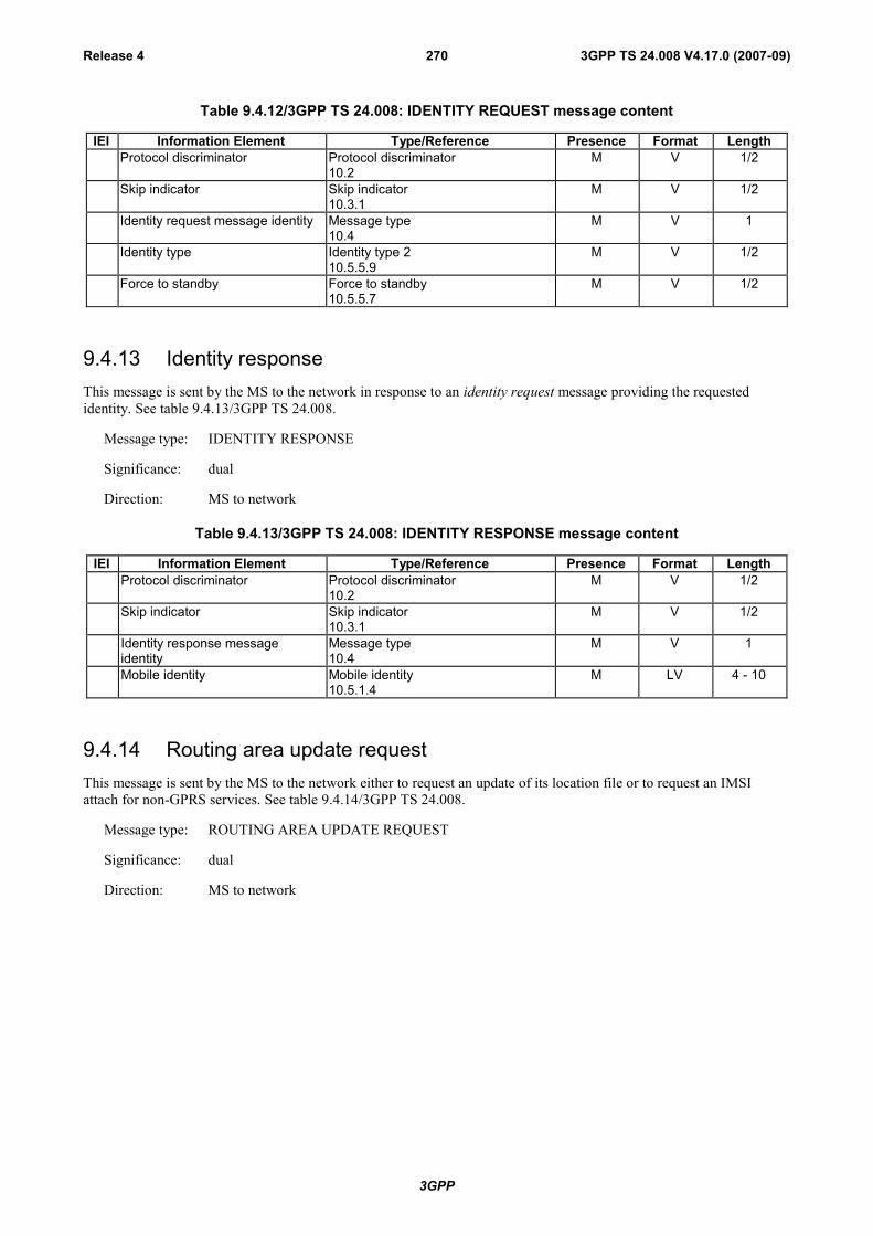
3GPP
3GPP TS 24.008 V4.17.0 (2007-09)Release 4 270
Table 9.4.12/3GPP TS 24.008: IDENTITY REQUEST message content
IEI Information Element Type/Reference Presence Format LengthProtocol discriminator Protocol discriminator
10.2M V 1/2
Skip indicator Skip indicator10.3.1
M V 1/2
Identity request message identity Message type10.4
M V 1
Identity type Identity type 210.5.5.9
M V 1/2
Force to standby Force to standby10.5.5.7
M V 1/2
9.4.13 Identity responseThis message is sent by the MS to the network in response to an identity request message providing the requestedidentity. See table 9.4.13/3GPP TS 24.008.
Message type: IDENTITY RESPONSE
Significance: dual
Direction: MS to network
Table 9.4.13/3GPP TS 24.008: IDENTITY RESPONSE message content
IEI Information Element Type/Reference Presence Format LengthProtocol discriminator Protocol discriminator
10.2M V 1/2
Skip indicator Skip indicator10.3.1
M V 1/2
Identity response messageidentity
Message type10.4
M V 1
Mobile identity Mobile identity10.5.1.4
M LV 4 - 10
9.4.14 Routing area update requestThis message is sent by the MS to the network either to request an update of its location file or to request an IMSIattach for non-GPRS services. See table 9.4.14/3GPP TS 24.008.
Message type: ROUTING AREA UPDATE REQUEST
Significance: dual
Direction: MS to network

3GPP
3GPP TS 24.008 V4.17.0 (2007-09)Release 4 271
Table 9.4.14/3GPP TS 24.008: ROUTING AREA UPDATE REQUEST message content
IEI Information Element Type/Reference Presence Format LengthProtocol discriminator Protocol discriminator
10.2M V 1/2
Skip indicator Skip indicator10.3.1
M V 1/2
Routing area update requestmessage identity
Message type10.4
M V 1
Update type Update type10.5.5.18
M V 1/2
GPRS ciphering key sequencenumber
Ciphering key sequence number10.5.1.2
M V 1/2
Old routing area identification Routing area identification10.5.5.15
M V 6
MS Radio Access capability MS Radio Access capability10.5.5.12a
M LV 6 - 52
19 Old P-TMSI signature P-TMSI signature10.5.5.8
O TV 4
17 Requested READY timer value GPRS Timer10.5.7.3
O TV 2
27 DRX parameter DRX parameter10.5.5.6
O TV 3
9- TMSI status TMSI status10.5.5.4
O TV 1
18 P-TMSI Mobile identity10.5.1.4
O TLV 7
31 MS network capability MS network capability10.5.5.12
O TLV 4-10
32 PDP context status PDP context status10.5.7.1
O TLV 4
9.4.14.1 Old P-TMSI signature
This IE is included by the MS if it was received from the network in an ATTACH ACCEPT or ROUTING AREAUPDATE ACCEPT message.
9.4.14.2 Requested READY timer value
This IE may be included if the MS wants to indicate a preferred value for the READY timer.
9.4.14.3 DRX parameter
This IE shall be included if the MS changes the access network from GSM to UMTS, or the MS wants to indicate newDRX parameters to the network.
9.4.14.4 TMSI status
This IE shall be included if the MS performs a combined routing area update and no valid TMSI is available.
9.4.14.5 P-TMSI (UMTS only)
This IE shall be included by the MS.
9.4.14.6 MS network capability
This IE shall be included by the MS to indicate it’s capabilities to the network.
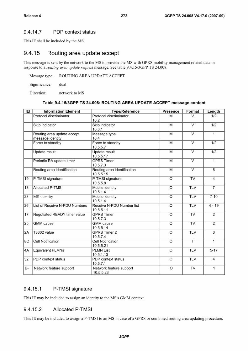
3GPP
3GPP TS 24.008 V4.17.0 (2007-09)Release 4 272
9.4.14.7 PDP context status
This IE shall be included by the MS.
9.4.15 Routing area update acceptThis message is sent by the network to the MS to provide the MS with GPRS mobility management related data inresponse to a routing area update request message. See table 9.4.15/3GPP TS 24.008.
Message type: ROUTING AREA UPDATE ACCEPT
Significance: dual
Direction: network to MS
Table 9.4.15/3GPP TS 24.008: ROUTING AREA UPDATE ACCEPT message content
IEI Information Element Type/Reference Presence Format LengthProtocol discriminator Protocol discriminator
10.2M V 1/2
Skip indicator Skip indicator10.3.1
M V 1/2
Routing area update acceptmessage identity
Message type10.4
M V 1
Force to standby Force to standby10.5.5.7
M V 1/2
Update result Update result10.5.5.17
M V 1/2
Periodic RA update timer GPRS Timer10.5.7.3
M V 1
Routing area identification Routing area identification10.5.5.15
M V 6
19 P-TMSI signature P-TMSI signature10.5.5.8
O TV 4
18 Allocated P-TMSI Mobile identity10.5.1.4
O TLV 7
23 MS identity Mobile identity10.5.1.4
O TLV 7-10
26 List of Receive N-PDU Numbers Receive N-PDU Number list10.5.5.11
O TLV 4 - 19
17 Negotiated READY timer value GPRS Timer10.5.7.3
O TV 2
25 GMM cause GMM cause10.5.5.14
O TV 2
2A T3302 value GPRS Timer 210.5.7.4
O TLV 3
8C Cell Notification Cell Notification10.5.5.21
O T 1
4A Equivalent PLMNs PLMN List10.5.1.13
O TLV 5-17
32 PDP context status PDP context status10.5.7.1
O TLV 4
B- Network feature support Network feature support10.5.5.23
O TV 1
9.4.15.1 P-TMSI signature
This IE may be included to assign an identity to the MS's GMM context.
9.4.15.2 Allocated P-TMSI
This IE may be included to assign a P-TMSI to an MS in case of a GPRS or combined routing area updating procedure.

3GPP
3GPP TS 24.008 V4.17.0 (2007-09)Release 4 273
9.4.15.3 MS identity
This IE may be included to assign or unassign a TMSI to a MS in case of a combined routing area updating procedure.
9.4.15.4 List of Receive N-PDU Numbers
This IE shall be included in case of an inter SGSN routing area updating, if there are PDP contexts that have beenactivated in acknowledged transfer mode.
9.4.15.5 Negotiated READY timer value
This IE may be included to indicate a value for the READY timer.
9.4.15.6 GMM cause
This IE shall be included if a combined GPRS routing area updating procedure was successful for GPRS services only.
9.4.15.7 T3302 value
This IE may be included to indicate a value for the T3302 timer.
9.4.15.8 Cell Notification (GSM only)
In GSM, this IE shall be included if by the SGSN in order to indicate the ability to support the Cell Notification.
9.4.15.9 Equivalent PLMNs
The Equivalent PLMNs information element is included if the network wants to inform the mobile station of equivalentPLMNs.
9.4.15.10 PDP context status
This IE shall be included by the NW.
9.4.15.11 Network feature support
This IE may be included to inform the MS of the support of certain features. If this IE is not included then therespective features are not supported.
9.4.16 Routing area update completeThis message shall be sent by the MS to the network in response to a routing area update accept message if a P-TMSIand/or a TMSI has been assigned and/or if there are established LLC connections. See table 9.4.16/3GPP TS 24.008.
Message type: ROUTING AREA UPDATE COMPLETE
Significance: dual
Direction: MS to network

3GPP
3GPP TS 24.008 V4.17.0 (2007-09)Release 4 274
Table 9.4.16/3GPP TS 24.008: ROUTING AREA UPDATE COMPLETE message content
IEI Information Element Type/Reference Presence Format LengthProtocol discriminator Protocol discriminator
10.2M V 1/2
Skip indicator Skip indicator10.3.1
M V 1/2
Routing area update completemessage identity
Message type10.4
M V 1
26 List of Receive N-PDU Numbers Receive N-PDU Number list10.5.5.11
O TLV 4 - 19
9.4.16.1 List of Receive N-PDU Numbers
This IE shall be included if the routing area update accept message contained this IE.
9.4.17 Routing area update rejectThis message is sent by the network to the MS in order to reject the routing area update procedure. Seetable 9.4.17/3GPP TS 24.008.
Message type: ROUTING AREA UPDATE REJECT
Significance: dual
Direction: network to MS
Table 9.4.17/3GPP TS 24.008: ROUTING AREA UPDATE REJECT message content
IEI Information Element Type/Reference Presence Format LengthProtocol discriminator Protocol discriminator
10.2M V 1/2
Skip indicator Skip indicator10.3.1
M V 1/2
Routing area update rejectmessage identity
Message type10.4
M V 1
GMM cause GMM cause10.5.5.14
M V 1
Force to standby Force to standby10.5.5.7
M V 1/2
Spare half octet Spare half octet10.5.1.8
M V 1/2
2A T3302 value GPRS Timer 210.5.7.4
O TLV 3
9.4.17.1 T3302 value
This IE may be included to indicate a value for the T3302 timer.
9.4.18 GMM StatusThis message is sent by the MS or by the network at any time to report certain error conditions listed in clause 8. Seetable 9.4.18/3GPP TS 24.008.
Message type: GMM STATUS
Significance: local
Direction: both
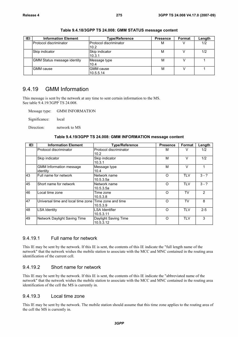
3GPP
3GPP TS 24.008 V4.17.0 (2007-09)Release 4 275
Table 9.4.18/3GPP TS 24.008: GMM STATUS message content
IEI Information Element Type/Reference Presence Format LengthProtocol discriminator Protocol discriminator
10.2M V 1/2
Skip indicator Skip indicator10.3.1
M V 1/2
GMM Status message identity Message type10.4
M V 1
GMM cause GMM cause10.5.5.14
M V 1
9.4.19 GMM InformationThis message is sent by the network at any time to sent certain information to the MS.See table 9.4.19/3GPP TS 24.008.
Message type: GMM INFORMATION
Significance: local
Direction: network to MS
Table 9.4.19/3GPP TS 24.008: GMM INFORMATION message content
IEI Information Element Type/Reference Presence Format LengthProtocol discriminator Protocol discriminator
10.2M V 1/2
Skip indicator Skip indicator10.3.1
M V 1/2
GMM Information messageidentity
Message type10.4
M V 1
43 Full name for network Network name10.5.3.5a
O TLV 3 - ?
45 Short name for network Network name10.5.3.5a
O TLV 3 - ?
46 Local time zone Time zone10.5.3.8
O TV 2
47 Universal time and local time zone Time zone and time10.5.3.9
O TV 8
48 LSA Identity LSA Identifier10.5.3.11
O TLV 2-5
49 Network Daylight Saving Time Daylight Saving Time10.5.3.12
O TLV 3
9.4.19.1 Full name for network
This IE may be sent by the network. If this IE is sent, the contents of this IE indicate the "full length name of thenetwork" that the network wishes the mobile station to associate with the MCC and MNC contained in the routing areaidentification of the current cell.
9.4.19.2 Short name for network
This IE may be sent by the network. If this IE is sent, the contents of this IE indicate the "abbreviated name of thenetwork" that the network wishes the mobile station to associate with the MCC and MNC contained in the routing areaidentification of the cell the MS is currently in.
9.4.19.3 Local time zone
This IE may be sent by the network. The mobile station should assume that this time zone applies to the routing area ofthe cell the MS is currently in.
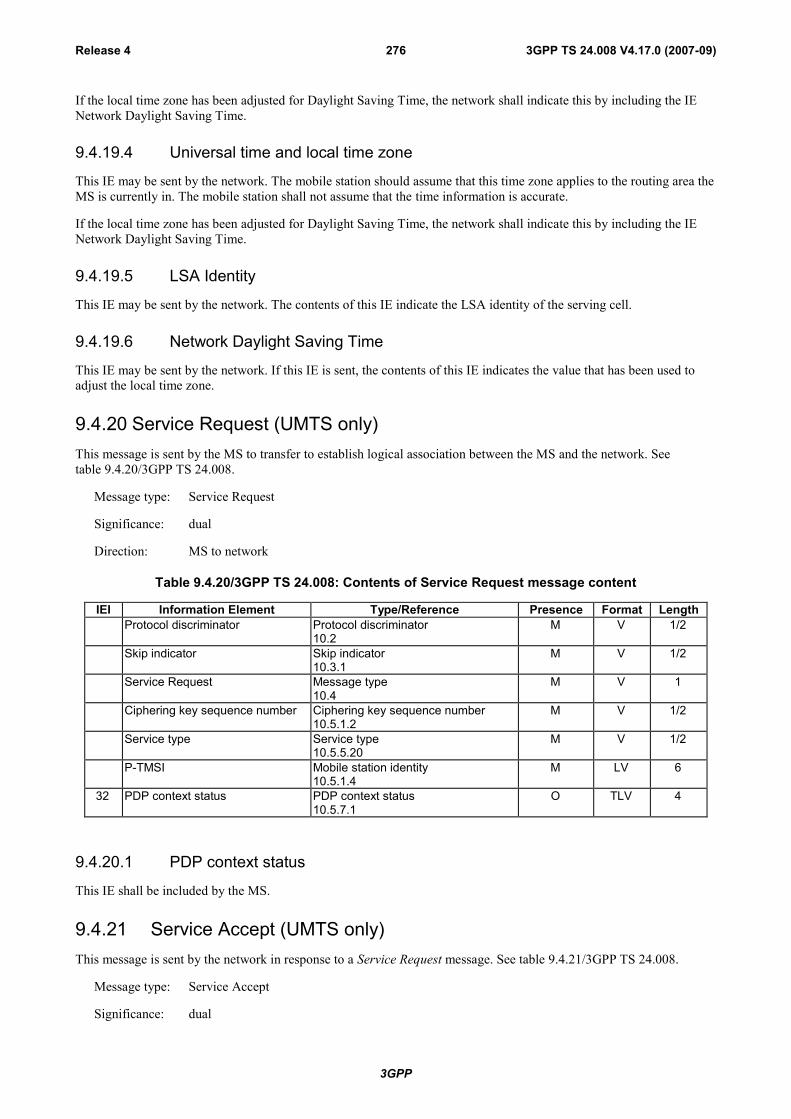
3GPP
3GPP TS 24.008 V4.17.0 (2007-09)Release 4 276
If the local time zone has been adjusted for Daylight Saving Time, the network shall indicate this by including the IENetwork Daylight Saving Time.
9.4.19.4 Universal time and local time zone
This IE may be sent by the network. The mobile station should assume that this time zone applies to the routing area theMS is currently in. The mobile station shall not assume that the time information is accurate.
If the local time zone has been adjusted for Daylight Saving Time, the network shall indicate this by including the IENetwork Daylight Saving Time.
9.4.19.5 LSA Identity
This IE may be sent by the network. The contents of this IE indicate the LSA identity of the serving cell.
9.4.19.6 Network Daylight Saving Time
This IE may be sent by the network. If this IE is sent, the contents of this IE indicates the value that has been used toadjust the local time zone.
9.4.20 Service Request (UMTS only)This message is sent by the MS to transfer to establish logical association between the MS and the network. Seetable 9.4.20/3GPP TS 24.008.
Message type: Service Request
Significance: dual
Direction: MS to network
Table 9.4.20/3GPP TS 24.008: Contents of Service Request message content
IEI Information Element Type/Reference Presence Format LengthProtocol discriminator Protocol discriminator
10.2M V 1/2
Skip indicator Skip indicator10.3.1
M V 1/2
Service Request Message type10.4
M V 1
Ciphering key sequence number Ciphering key sequence number10.5.1.2
M V 1/2
Service type Service type10.5.5.20
M V 1/2
P-TMSI Mobile station identity10.5.1.4
M LV 6
32 PDP context status PDP context status10.5.7.1
O TLV 4
9.4.20.1 PDP context status
This IE shall be included by the MS.
9.4.21 Service Accept (UMTS only)This message is sent by the network in response to a Service Request message. See table 9.4.21/3GPP TS 24.008.
Message type: Service Accept
Significance: dual
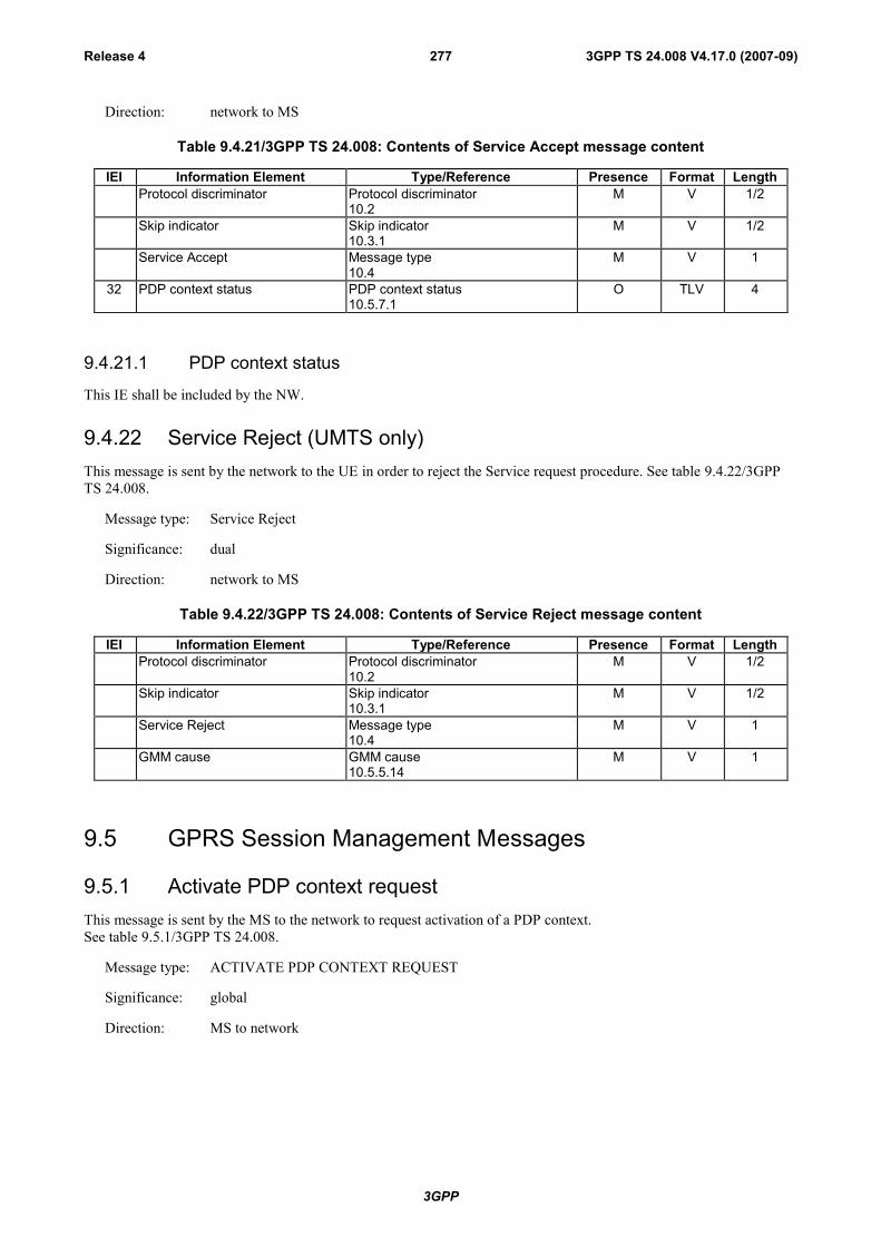
3GPP
3GPP TS 24.008 V4.17.0 (2007-09)Release 4 277
Direction: network to MS
Table 9.4.21/3GPP TS 24.008: Contents of Service Accept message content
IEI Information Element Type/Reference Presence Format LengthProtocol discriminator Protocol discriminator
10.2M V 1/2
Skip indicator Skip indicator10.3.1
M V 1/2
Service Accept Message type10.4
M V 1
32 PDP context status PDP context status10.5.7.1
O TLV 4
9.4.21.1 PDP context status
This IE shall be included by the NW.
9.4.22 Service Reject (UMTS only)This message is sent by the network to the UE in order to reject the Service request procedure. See table 9.4.22/3GPPTS 24.008.
Message type: Service Reject
Significance: dual
Direction: network to MS
Table 9.4.22/3GPP TS 24.008: Contents of Service Reject message content
IEI Information Element Type/Reference Presence Format LengthProtocol discriminator Protocol discriminator
10.2M V 1/2
Skip indicator Skip indicator10.3.1
M V 1/2
Service Reject Message type10.4
M V 1
GMM cause GMM cause10.5.5.14
M V 1
9.5 GPRS Session Management Messages
9.5.1 Activate PDP context requestThis message is sent by the MS to the network to request activation of a PDP context.See table 9.5.1/3GPP TS 24.008.
Message type: ACTIVATE PDP CONTEXT REQUEST
Significance: global
Direction: MS to network

3GPP
3GPP TS 24.008 V4.17.0 (2007-09)Release 4 278
Table 9.5.1/3GPP TS 24.008: ACTIVATE PDP CONTEXT REQUEST message content
IEI Information Element Type/Reference Presence Format LengthProtocol discriminator Protocol discriminator
10.2M V 1/2
Transaction identifier Transaction identifier10.3.2
M V 1/2– 3/2
Activate PDP context requestmessage identity
Message type10.4
M V 1
Requested NSAPI Network service access point identifier10.5.6.2
M V 1
Requested LLC SAPI LLC service access point identifier10.5.6.9
M V 1
Requested QoS Quality of service10.5.6.5
M LV 12
Requested PDP address Packet data protocol address10.5.6.4
M LV 3 - 19
28 Access point name Access point name10.5.6.1
O TLV 3 - 102
27 Protocol configuration options Protocol configuration options10.5.6.3
O TLV 3 - 253
9.5.1.1 Access point name
This IE is included in the message when the MS selects a specific external network to be connected to.
9.5.1.2 Protocol configuration options
This IE is included in the message when the MS provides protocol configuration options for the external PDN.
9.5.2 Activate PDP context acceptThis message is sent by the network to the MS to acknowledge activation of a PDP context.See table 9.5.2/3GPP TS 24.008.
Message type: ACTIVATE PDP CONTEXT ACCEPT
Significance: global
Direction: network to MS
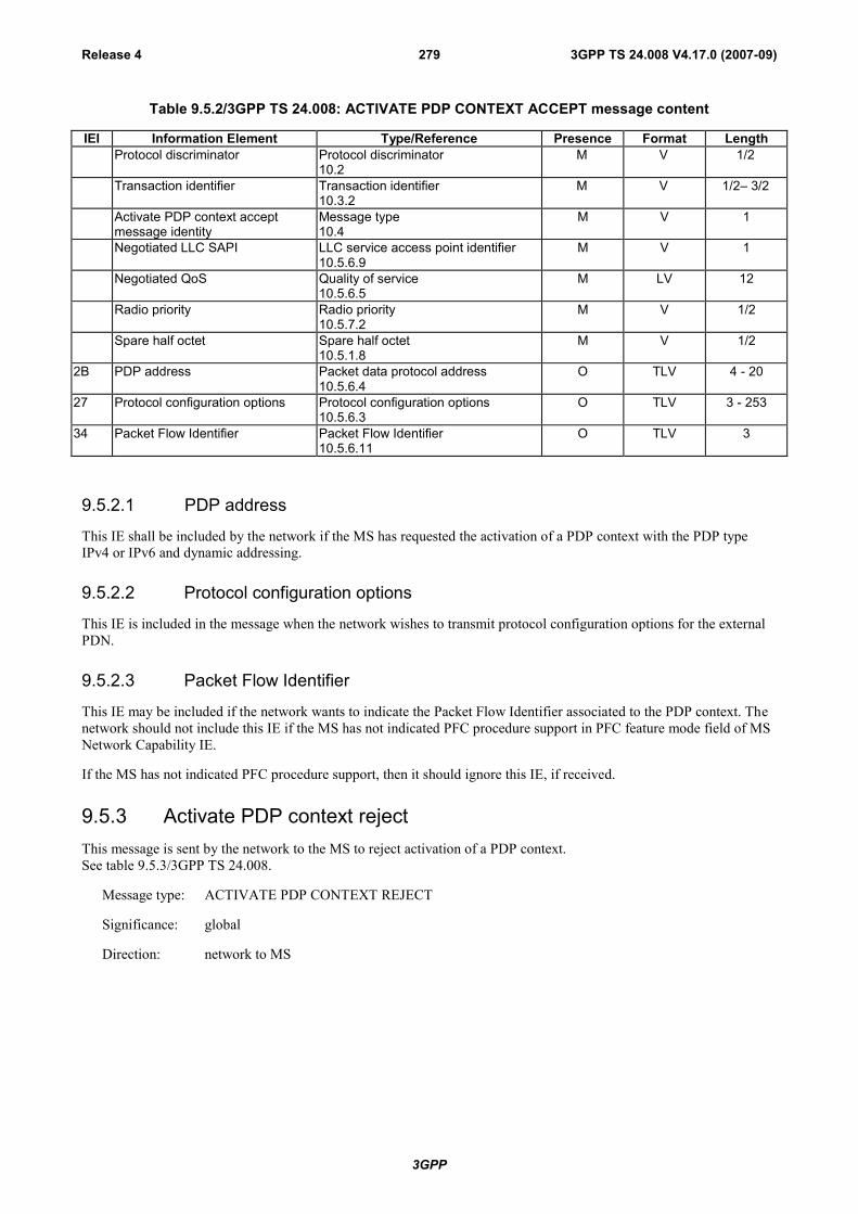
3GPP
3GPP TS 24.008 V4.17.0 (2007-09)Release 4 279
Table 9.5.2/3GPP TS 24.008: ACTIVATE PDP CONTEXT ACCEPT message content
IEI Information Element Type/Reference Presence Format LengthProtocol discriminator Protocol discriminator
10.2M V 1/2
Transaction identifier Transaction identifier10.3.2
M V 1/2– 3/2
Activate PDP context acceptmessage identity
Message type10.4
M V 1
Negotiated LLC SAPI LLC service access point identifier10.5.6.9
M V 1
Negotiated QoS Quality of service10.5.6.5
M LV 12
Radio priority Radio priority10.5.7.2
M V 1/2
Spare half octet Spare half octet10.5.1.8
M V 1/2
2B PDP address Packet data protocol address10.5.6.4
O TLV 4 - 20
27 Protocol configuration options Protocol configuration options10.5.6.3
O TLV 3 - 253
34 Packet Flow Identifier Packet Flow Identifier10.5.6.11
O TLV 3
9.5.2.1 PDP address
This IE shall be included by the network if the MS has requested the activation of a PDP context with the PDP typeIPv4 or IPv6 and dynamic addressing.
9.5.2.2 Protocol configuration options
This IE is included in the message when the network wishes to transmit protocol configuration options for the externalPDN.
9.5.2.3 Packet Flow Identifier
This IE may be included if the network wants to indicate the Packet Flow Identifier associated to the PDP context. Thenetwork should not include this IE if the MS has not indicated PFC procedure support in PFC feature mode field of MSNetwork Capability IE.
If the MS has not indicated PFC procedure support, then it should ignore this IE, if received.
9.5.3 Activate PDP context rejectThis message is sent by the network to the MS to reject activation of a PDP context.See table 9.5.3/3GPP TS 24.008.
Message type: ACTIVATE PDP CONTEXT REJECT
Significance: global
Direction: network to MS
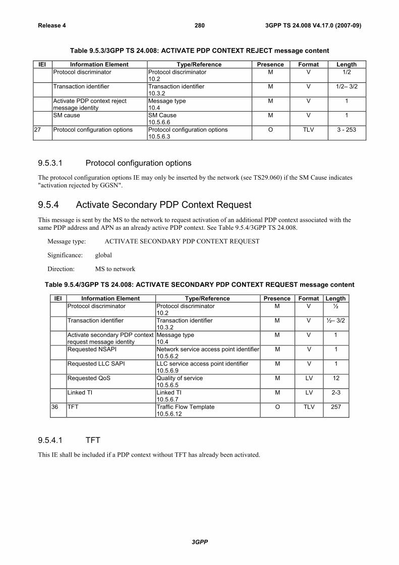
3GPP
3GPP TS 24.008 V4.17.0 (2007-09)Release 4 280
Table 9.5.3/3GPP TS 24.008: ACTIVATE PDP CONTEXT REJECT message content
IEI Information Element Type/Reference Presence Format LengthProtocol discriminator Protocol discriminator
10.2M V 1/2
Transaction identifier Transaction identifier10.3.2
M V 1/2– 3/2
Activate PDP context rejectmessage identity
Message type10.4
M V 1
SM cause SM Cause10.5.6.6
M V 1
27 Protocol configuration options Protocol configuration options10.5.6.3
O TLV 3 - 253
9.5.3.1 Protocol configuration options
The protocol configuration options IE may only be inserted by the network (see TS29.060) if the SM Cause indicates"activation rejected by GGSN".
9.5.4 Activate Secondary PDP Context RequestThis message is sent by the MS to the network to request activation of an additional PDP context associated with thesame PDP address and APN as an already active PDP context. See Table 9.5.4/3GPP TS 24.008.
Message type: ACTIVATE SECONDARY PDP CONTEXT REQUEST
Significance: global
Direction: MS to network
Table 9.5.4/3GPP TS 24.008: ACTIVATE SECONDARY PDP CONTEXT REQUEST message content
IEI Information Element Type/Reference Presence Format LengthProtocol discriminator Protocol discriminator
10.2M V ½
Transaction identifier Transaction identifier10.3.2
M V ½– 3/2
Activate secondary PDP contextrequest message identity
Message type10.4
M V 1
Requested NSAPI Network service access point identifier10.5.6.2
M V 1
Requested LLC SAPI LLC service access point identifier10.5.6.9
M V 1
Requested QoS Quality of service10.5.6.5
M LV 12
Linked TI Linked TI10.5.6.7
M LV 2-3
36 TFT Traffic Flow Template10.5.6.12
O TLV 257
9.5.4.1 TFT
This IE shall be included if a PDP context without TFT has already been activated.

3GPP
3GPP TS 24.008 V4.17.0 (2007-09)Release 4 281
9.5.5 Activate Secondary PDP Context AcceptThis message is sent by the network to the MS to acknowledge activation of an additional PDP context associated withthe same PDP address and APN as an already active PDP context. See Table 9.5.5/3GPP TS 24.008.
Message type: ACTIVATE SECONDARY PDP CONTEXT ACCEPT
Significance: global
Direction: network to MS
Table 9.5.5/3GPP TS 24.008: ACTIVATE SECONDARY PDP CONTEXT ACCEPT message content
IEI Information Element Type/Reference Presence Format LengthProtocol discriminator Protocol discriminator
10.2M V 1/2
Transaction identifier Transaction identifier10.3.2
M V 1/2– 3/2
Activate secondary PDP contextaccept message identity
Message type10.4
M V 1
Negotiated LLC SAPI LLC service access point identifier10.5.6.9
M V 1
Negotiated QoS Quality of service10.5.6.5
M LV 12
Radio priority Radio priority M V 1/2Spare half octet Spare half octet
10.5.1.8M V 1/2
34 Packet Flow Identifier Packet Flow Identifier10.5.6.11
O TLV 3
9.5.5.1 Packet Flow Identifier
This IE may be included if the network wants to indicate the Packet Flow Identifier associated to the PDP context. Thenetwork should not include this IE if the MS has not indicated PFC procedure support in PFC feature mode field of MSNetwork Capability IE.
If the MS has not indicated PFC procedure support, then it should ignore this IE, if received.
9.5.6 Activate Secondary PDP Context RejectThis message is sent by the network to the UE to reject activation of an additional PDP context associated with the samePDP address and APN as an already active PDP context. See Table 9.5.6/3GPP TS 24.008.
Message type: ACTIVATE SECONDARY PDP CONTEXT REJECT
Significance: global
Direction: network to MS
Table 9.5.6/3GPP TS 24.008: ACTIVATE SECONDARY PDP CONTEXT REJECT message content
IEI Information Element Type/Reference Presence Format LengthProtocol discriminator Protocol discriminator
10.2M V 1/2
Transaction identifier Transaction identifier10.3.2
M V 1/2– 3/2
Activate secondary PDP contextreject message identity
Message type10.4
M V 1
SM cause SM Cause10.5.6.6
M V 1
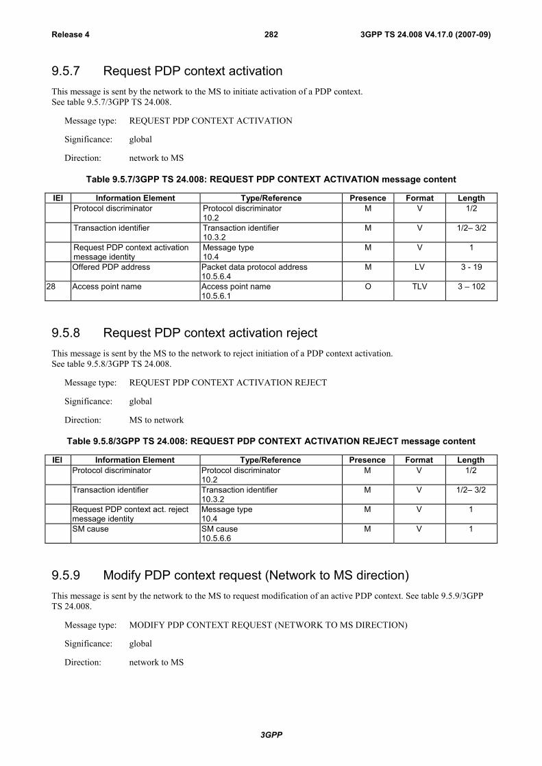
3GPP
3GPP TS 24.008 V4.17.0 (2007-09)Release 4 282
9.5.7 Request PDP context activationThis message is sent by the network to the MS to initiate activation of a PDP context.See table 9.5.7/3GPP TS 24.008.
Message type: REQUEST PDP CONTEXT ACTIVATION
Significance: global
Direction: network to MS
Table 9.5.7/3GPP TS 24.008: REQUEST PDP CONTEXT ACTIVATION message content
IEI Information Element Type/Reference Presence Format LengthProtocol discriminator Protocol discriminator
10.2M V 1/2
Transaction identifier Transaction identifier10.3.2
M V 1/2– 3/2
Request PDP context activationmessage identity
Message type10.4
M V 1
Offered PDP address Packet data protocol address10.5.6.4
M LV 3 - 19
28 Access point name Access point name10.5.6.1
O TLV 3 – 102
9.5.8 Request PDP context activation rejectThis message is sent by the MS to the network to reject initiation of a PDP context activation.See table 9.5.8/3GPP TS 24.008.
Message type: REQUEST PDP CONTEXT ACTIVATION REJECT
Significance: global
Direction: MS to network
Table 9.5.8/3GPP TS 24.008: REQUEST PDP CONTEXT ACTIVATION REJECT message content
IEI Information Element Type/Reference Presence Format LengthProtocol discriminator Protocol discriminator
10.2M V 1/2
Transaction identifier Transaction identifier10.3.2
M V 1/2– 3/2
Request PDP context act. rejectmessage identity
Message type10.4
M V 1
SM cause SM cause10.5.6.6
M V 1
9.5.9 Modify PDP context request (Network to MS direction)This message is sent by the network to the MS to request modification of an active PDP context. See table 9.5.9/3GPPTS 24.008.
Message type: MODIFY PDP CONTEXT REQUEST (NETWORK TO MS DIRECTION)
Significance: global
Direction: network to MS

3GPP
3GPP TS 24.008 V4.17.0 (2007-09)Release 4 283
Table 9.5.9/3GPP TS 24.008: MODIFY PDP CONTEXT REQUEST (NETWORK TO MS DIRECTION)message content
IEI Information Element Type/Reference Presence Format LengthProtocol discriminator Protocol discriminator
10.2M V 1/2
Transaction identifier Transaction identifier10.3.2
M V 1/2– 3/2
Modify PDP context requestmessage identity
Message type10.4
M V 1
Radio priority Radio priority10.5.7.2
M V 1/2
Spare half octet Spare half octet10.5.1.8
M V 1/2
Requested LLC SAPI LLC service access point identifier10.5.6.9
M V 1
New QoS Quality of service10.5.6.5
M LV 12
2B PDP address Packet data protocol address10.5.6.4
O TLV 4-20
34 Packet Flow Identifier Packet Flow Identifier10.5.6.11
O TLV 3
9.5.9.1 PDP address
If the MS requested external PDN address allocation at PDP context activation via an APN and this was confirmed bythe network in the ACTIVATE PDP CONTEXT ACCEPT message, then the network shall include the PDP address IEin the MODIFY PDP CONTEXT REQUEST message once the address has been actually allocated, in order to updatethe PDP context in the MS.
9.5.9.2 Packet Flow Identifier
This IE may be included if the network wants to indicate the Packet Flow Identifier associated to the PDP context. Thenetwork should not include this IE if the MS has not indicated PFC procedure support in PFC feature mode field of MSNetwork Capability IE.
If the MS has not indicated PFC procedure support, then it should ignore this IE, if received.
9.5.10 Modify PDP context request (MS to network direction)This message is sent by the MS to the network to request modification of an active PDP context. See table 9.5.10/3GPPTS 24.008.
Message type: MODIFY PDP CONTEXT REQUEST (MS TO NETWORK DIRECTION)
Significance: global
Direction: MS to network

3GPP
3GPP TS 24.008 V4.17.0 (2007-09)Release 4 284
Table 9.5.10/3GPP TS 24.008: MODIFY PDP CONTEXT REQUEST (MS to network direction) messagecontent
IEI Information Element Type/Reference Presence Format LengthProtocol discriminator Protocol discriminator
10.2M V 1/2
Transaction identifier Transaction identifier10.3.2
M V 1/2– 3/2
Modify PDP context requestmessage identity
Message type10.4
M V 1
32 Requested LLC SAPI LLC service access point identifier10.5.6.9
O TV 2
30 Requested new QoS Quality of service10.5.6.5
O TLV 13
31 New TFT Traffic Flow Template10.5.6.12
O TLV 257
9.5.10.1 Requested LLC SAPI
This IE may be included in the message to request a new LLC SAPI if a new QoS is requested.
9.5.10.2 Requested new QoS
This IE may be included in the message to request a modification of the QoS.
9.5.10.3 New TFT
This IE may be included in the message to request a new TFT or modification of an existing TFT.
9.5.11 Modify PDP context accept (MS to network direction)This message is sent by the MS to the network to acknowledge the modification of an active PDP context. Seetable 9.5.11/3GPP TS 24.008.
Message type: MODIFY PDP CONTEXT ACCEPT (MS TO NETWORK DIRECTION)
Significance: global
Direction: MS to network
Table 9.5.11/3GPP TS 24.008: MODIFY PDP CONTEXT ACCEPT (MS TO NETWORK DIRECTION)message content
IEI Information Element Type/Reference Presence Format LengthProtocol discriminator Protocol discriminator
10.2M V 1/2
Transaction identifier Transaction identifier10.3.2
M V 1/2– 3/2
Modify PDP context acceptmessage identity
Message type10.4
M V 1
9.5.12 Modify PDP context accept (Network to MS direction)This message is sent by the network to the MS to acknowledge the modification of an active PDP context. Seetable 9.5.12/3GPP TS 24.008.
Message type: MODIFY PDP CONTEXT ACCEPT (NETWORK TO MS DIRECTION)
Significance: global
Direction: Network to MS
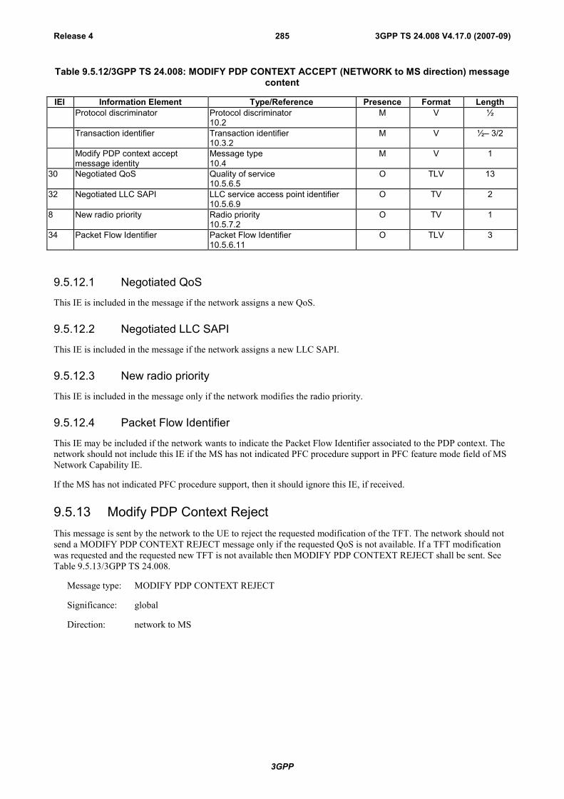
3GPP
3GPP TS 24.008 V4.17.0 (2007-09)Release 4 285
Table 9.5.12/3GPP TS 24.008: MODIFY PDP CONTEXT ACCEPT (NETWORK to MS direction) messagecontent
IEI Information Element Type/Reference Presence Format LengthProtocol discriminator Protocol discriminator
10.2M V ½
Transaction identifier Transaction identifier10.3.2
M V ½– 3/2
Modify PDP context acceptmessage identity
Message type10.4
M V 1
30 Negotiated QoS Quality of service10.5.6.5
O TLV 13
32 Negotiated LLC SAPI LLC service access point identifier10.5.6.9
O TV 2
8 New radio priority Radio priority10.5.7.2
O TV 1
34 Packet Flow Identifier Packet Flow Identifier10.5.6.11
O TLV 3
9.5.12.1 Negotiated QoS
This IE is included in the message if the network assigns a new QoS.
9.5.12.2 Negotiated LLC SAPI
This IE is included in the message if the network assigns a new LLC SAPI.
9.5.12.3 New radio priority
This IE is included in the message only if the network modifies the radio priority.
9.5.12.4 Packet Flow Identifier
This IE may be included if the network wants to indicate the Packet Flow Identifier associated to the PDP context. Thenetwork should not include this IE if the MS has not indicated PFC procedure support in PFC feature mode field of MSNetwork Capability IE.
If the MS has not indicated PFC procedure support, then it should ignore this IE, if received.
9.5.13 Modify PDP Context RejectThis message is sent by the network to the UE to reject the requested modification of the TFT. The network should notsend a MODIFY PDP CONTEXT REJECT message only if the requested QoS is not available. If a TFT modificationwas requested and the requested new TFT is not available then MODIFY PDP CONTEXT REJECT shall be sent. SeeTable 9.5.13/3GPP TS 24.008.
Message type: MODIFY PDP CONTEXT REJECT
Significance: global
Direction: network to MS
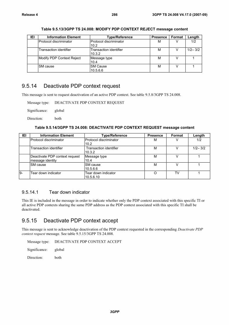
3GPP
3GPP TS 24.008 V4.17.0 (2007-09)Release 4 286
Table 9.5.13/3GPP TS 24.008: MODIFY PDP CONTEXT REJECT message content
IEI Information Element Type/Reference Presence Format LengthProtocol discriminator Protocol discriminator
10.2M V 1/2
Transaction identifier Transaction identifier10.3.2
M V 1/2– 3/2
Modify PDP Context Reject Message type10.4
M V 1
SM cause SM Cause10.5.6.6
M V 1
9.5.14 Deactivate PDP context requestThis message is sent to request deactivation of an active PDP context. See table 9.5.8/3GPP TS 24.008.
Message type: DEACTIVATE PDP CONTEXT REQUEST
Significance: global
Direction: both
Table 9.5.14/3GPP TS 24.008: DEACTIVATE PDP CONTEXT REQUEST message content
IEI Information Element Type/Reference Presence Format LengthProtocol discriminator Protocol discriminator
10.2M V 1/2
Transaction identifier Transaction identifier10.3.2
M V 1/2– 3/2
Deactivate PDP context requestmessage identity
Message type10.4
M V 1
SM cause SM cause10.5.6.6
M V 1
9- Tear down indicator Tear down indicator10.5.6.10
O TV 1
9.5.14.1 Tear down indicator
This IE is included in the message in order to indicate whether only the PDP context associated with this specific TI orall active PDP contexts sharing the same PDP address as the PDP context associated with this specific TI shall bedeactivated.
9.5.15 Deactivate PDP context acceptThis message is sent to acknowledge deactivation of the PDP context requested in the corresponding Deactivate PDPcontext request message. See table 9.5.15/3GPP TS 24.008.
Message type: DEACTIVATE PDP CONTEXT ACCEPT
Significance: global
Direction: both
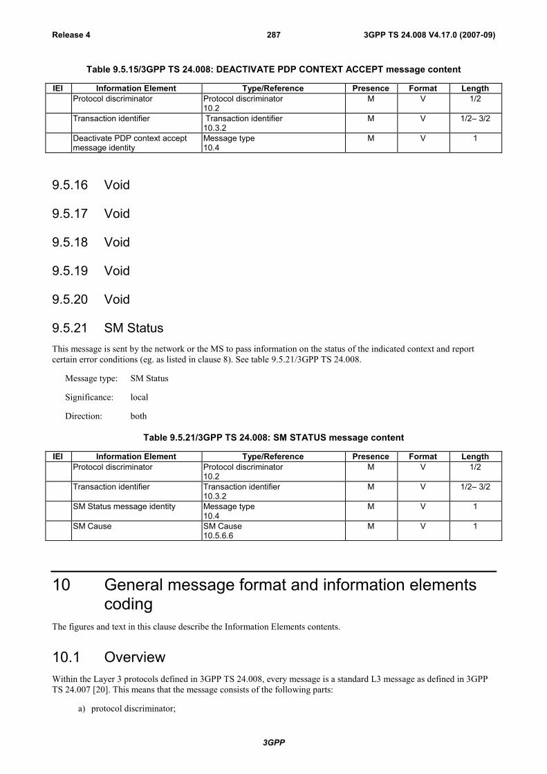
3GPP
3GPP TS 24.008 V4.17.0 (2007-09)Release 4 287
Table 9.5.15/3GPP TS 24.008: DEACTIVATE PDP CONTEXT ACCEPT message content
IEI Information Element Type/Reference Presence Format LengthProtocol discriminator Protocol discriminator
10.2M V 1/2
Transaction identifier Transaction identifier10.3.2
M V 1/2– 3/2
Deactivate PDP context acceptmessage identity
Message type10.4
M V 1
9.5.16 Void
9.5.17 Void
9.5.18 Void
9.5.19 Void
9.5.20 Void
9.5.21 SM StatusThis message is sent by the network or the MS to pass information on the status of the indicated context and reportcertain error conditions (eg. as listed in clause 8). See table 9.5.21/3GPP TS 24.008.
Message type: SM Status
Significance: local
Direction: both
Table 9.5.21/3GPP TS 24.008: SM STATUS message content
IEI Information Element Type/Reference Presence Format LengthProtocol discriminator Protocol discriminator
10.2M V 1/2
Transaction identifier Transaction identifier10.3.2
M V 1/2– 3/2
SM Status message identity Message type10.4
M V 1
SM Cause SM Cause10.5.6.6
M V 1
10 General message format and information elementscoding
The figures and text in this clause describe the Information Elements contents.
10.1 OverviewWithin the Layer 3 protocols defined in 3GPP TS 24.008, every message is a standard L3 message as defined in 3GPPTS 24.007 [20]. This means that the message consists of the following parts:
a) protocol discriminator;

3GPP
3GPP TS 24.008 V4.17.0 (2007-09)Release 4 288
b) transaction identifier;
c) message type;
d) other information elements, as required.
This organization is illustrated in the example shown in figure 10.1/3GPP TS 24.008.
Figure 10.1/3GPP TS 24.008 General message organization example
Unless specified otherwise in the message descriptions of clause 9, a particular information element shall not be presentmore than once in a given message.
The term "default" implies that the value defined shall be used in the absence of any assignment, or that this valueallows negotiation of alternative values in between the two peer entities.
When a field extends over more than one octet, the order of bit values progressively decreases as the octet numberincreases. The least significant bit of the field is represented by the lowest numbered bit of the highest numbered octetof the field.
10.2 Protocol DiscriminatorThe Protocol Discriminator (PD) and its use are defined in 3GPP TS 24.007 [20].
10.3 Skip indicator and transaction identifier
10.3.1 Skip indicatorBits 5 to 8 of the first octet of every Mobility Management message and GPRS MobilityManagement message containsthe skip indicator. A message received with skip indicator different from 0000 shall be ignored. A message receivedwith skip indicator encoded as 0000 shall not be ignored (unless it is ignored for other reasons). A protocol entitysending a Mobility Management message or a GPRS Mobility Management message shall encode the skip indicatoras 0000.
10.3.2 Transaction identifierBits 5 to 8 of the first octet of every message belonging to the protocols "Call Control; call related SS messages" and"Session Management"contain the transaction identifier (TI). The transaction identifier and its use are defined in 3GPPTS 24.007 [20].
For the session management protocol, the extended TI mechanism may be used (see 3GPP TS 24.007 [20]).
For the call control protocol, the extended TI mechanism shall be supported for the purpose of protocol error handlingas specified in subclause 8.3.1

3GPP
3GPP TS 24.008 V4.17.0 (2007-09)Release 4 289
10.4 Message TypeThe message type IE and its use are defined in 3GPP TS 24.007 [20]. Tables 10.3/3GPP TS 24.008,10.4/3GPP TS 24.008, and 10.4a/3GPP TS 24.008 define the value part of the message type IE used in the MobilityManagement protocol, the Call Control protocol, and Session management protocol.
Table 10.2/3GPP TS 24.008: Message types for Mobility Management
8 7 6 5 4 3 2 1
x x 0 0 - - - - Registration messages:0 0 0 1 - IMSI DETACH INDICATION0 0 1 0 - LOCATION UPDATING ACCEPT0 1 0 0 - LOCATION UPDATING REJECT1 0 0 0 - LOCATION UPDATING REQUEST
x x 0 1 - - - - Security messages:0 0 0 1 - AUTHENTICATION REJECT0 0 1 0 - AUTHENTICATION REQUEST0 1 0 0 - AUTHENTICATION RESPONSE1 1 0 0 - AUTHENTICATION FAILURE…………..1 0 0 0 - IDENTITY REQUEST1 0 0 1 - IDENTITY RESPONSE1 0 1 0 - TMSI REALLOCATION COMMAND1 0 1 1 - TMSI REALLOCATION COMPLETE
x x 1 0 - - - - Connection management messages:0 0 0 1 - CM SERVICE ACCEPT0 0 1 0 - CM SERVICE REJECT0 0 1 1 - CM SERVICE ABORT0 1 0 0 - CM SERVICE REQUEST0 1 0 1 - CM SERVICE PROMPT0 1 1 0 - Reserved (see NOTE)1 0 0 0 - CM RE-ESTABLISHMENT REQUEST1 0 0 1 - ABORT
x x 1 1 - - - - Miscellaneous messages:0 0 0 0 - MM NULL0 0 0 1 - MM STATUS0 0 1 0 - MM INFORMATION
NOTE: This value was allocated but never used in earlier phases of the protocol.
When the radio connection started with a core network node of earlier than R99, bit 8 shall be set to 0 and bit 7 isreserved for the send sequence number in messages sent from the mobile station. In messages sent from the network,bits 7 and 8 are coded with a "0". See 3GPP TS 24.007 [20].
When the radio connection started with a core network node of R'99 or later, bits 7 and 8 are reserved for the sendsequence number in messages sent from the mobile station. In messages sent from the network, bits 7 and 8 are codedwith a "0". See 3GPP TS 24.007 [20].
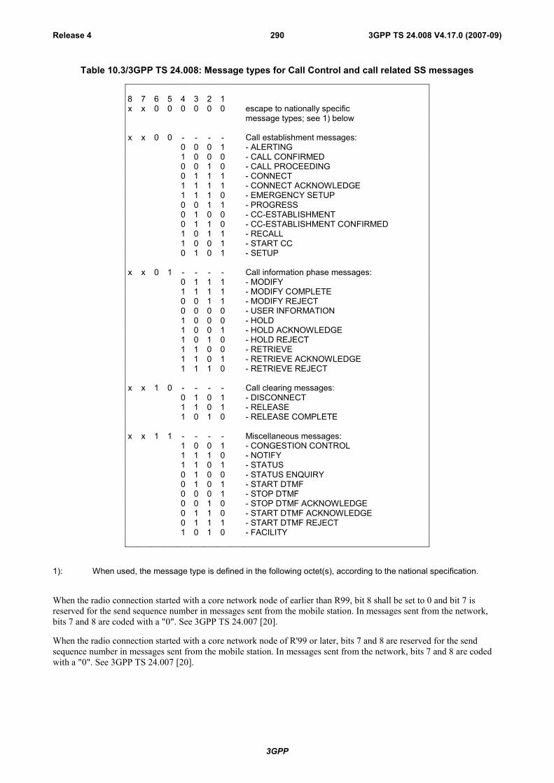
3GPP
3GPP TS 24.008 V4.17.0 (2007-09)Release 4 290
Table 10.3/3GPP TS 24.008: Message types for Call Control and call related SS messages
8 7 6 5 4 3 2 1x x 0 0 0 0 0 0 escape to nationally specific
message types; see 1) below
x x 0 0 - - - - Call establishment messages:0 0 0 1 - ALERTING1 0 0 0 - CALL CONFIRMED0 0 1 0 - CALL PROCEEDING0 1 1 1 - CONNECT1 1 1 1 - CONNECT ACKNOWLEDGE1 1 1 0 - EMERGENCY SETUP0 0 1 1 - PROGRESS0 1 0 0 - CC-ESTABLISHMENT0 1 1 0 - CC-ESTABLISHMENT CONFIRMED1 0 1 1 - RECALL1 0 0 1 - START CC0 1 0 1 - SETUP
x x 0 1 - - - - Call information phase messages:0 1 1 1 - MODIFY1 1 1 1 - MODIFY COMPLETE0 0 1 1 - MODIFY REJECT0 0 0 0 - USER INFORMATION1 0 0 0 - HOLD1 0 0 1 - HOLD ACKNOWLEDGE1 0 1 0 - HOLD REJECT1 1 0 0 - RETRIEVE1 1 0 1 - RETRIEVE ACKNOWLEDGE1 1 1 0 - RETRIEVE REJECT
x x 1 0 - - - - Call clearing messages:0 1 0 1 - DISCONNECT1 1 0 1 - RELEASE1 0 1 0 - RELEASE COMPLETE
x x 1 1 - - - - Miscellaneous messages:1 0 0 1 - CONGESTION CONTROL1 1 1 0 - NOTIFY1 1 0 1 - STATUS0 1 0 0 - STATUS ENQUIRY0 1 0 1 - START DTMF0 0 0 1 - STOP DTMF0 0 1 0 - STOP DTMF ACKNOWLEDGE0 1 1 0 - START DTMF ACKNOWLEDGE0 1 1 1 - START DTMF REJECT1 0 1 0 - FACILITY
1): When used, the message type is defined in the following octet(s), according to the national specification.
When the radio connection started with a core network node of earlier than R99, bit 8 shall be set to 0 and bit 7 isreserved for the send sequence number in messages sent from the mobile station. In messages sent from the network,bits 7 and 8 are coded with a "0". See 3GPP TS 24.007 [20].
When the radio connection started with a core network node of R'99 or later, bits 7 and 8 are reserved for the sendsequence number in messages sent from the mobile station. In messages sent from the network, bits 7 and 8 are codedwith a "0". See 3GPP TS 24.007 [20].

3GPP
3GPP TS 24.008 V4.17.0 (2007-09)Release 4 291
Table 10.4/3GPP TS 24.008: Message types for GPRS mobility management
Bits8 7 6 5 4 3 2 1
0 0 - - - - - - Mobility management messages
0 0 0 0 0 0 0 1 Attach request0 0 0 0 0 0 1 0 Attach accept0 0 0 0 0 0 1 1 Attach complete0 0 0 0 0 1 0 0 Attach reject0 0 0 0 0 1 0 1 Detach request0 0 0 0 0 1 1 0 Detach accept
0 0 0 0 1 0 0 0 Routing area update request0 0 0 0 1 0 0 1 Routing area update accept0 0 0 0 1 0 1 0 Routing area update complete0 0 0 0 1 0 1 1 Routing area update reject
0 0 0 0 1 1 0 0 Service Request0 0 0 0 1 1 0 1 Service Accept0 0 0 0 1 1 1 0 Service Reject
0 0 0 1 0 0 0 0 P-TMSI reallocation command0 0 0 1 0 0 0 1 P-TMSI reallocation complete0 0 0 1 0 0 1 0 Authentication and ciphering req0 0 0 1 0 0 1 1 Authentication and ciphering resp0 0 0 1 0 1 0 0 Authentication and ciphering rej0 0 0 1 1 1 0 0 Authentication and ciphering failure0 0 0 1 0 1 0 1 Identity request0 0 0 1 0 1 1 0 Identity response0 0 1 0 0 0 0 0 GMM status0 0 1 0 0 0 0 1 GMM information
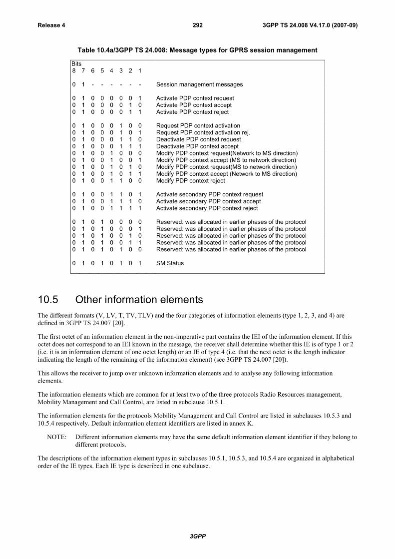
3GPP
3GPP TS 24.008 V4.17.0 (2007-09)Release 4 292
Table 10.4a/3GPP TS 24.008: Message types for GPRS session management
Bits8 7 6 5 4 3 2 1
0 1 - - - - - - Session management messages
0 1 0 0 0 0 0 1 Activate PDP context request0 1 0 0 0 0 1 0 Activate PDP context accept0 1 0 0 0 0 1 1 Activate PDP context reject
0 1 0 0 0 1 0 0 Request PDP context activation0 1 0 0 0 1 0 1 Request PDP context activation rej.0 1 0 0 0 1 1 0 Deactivate PDP context request0 1 0 0 0 1 1 1 Deactivate PDP context accept0 1 0 0 1 0 0 0 Modify PDP context request(Network to MS direction)0 1 0 0 1 0 0 1 Modify PDP context accept (MS to network direction)0 1 0 0 1 0 1 0 Modify PDP context request(MS to network direction)0 1 0 0 1 0 1 1 Modify PDP context accept (Network to MS direction)0 1 0 0 1 1 0 0 Modify PDP context reject
0 1 0 0 1 1 0 1 Activate secondary PDP context request0 1 0 0 1 1 1 0 Activate secondary PDP context accept0 1 0 0 1 1 1 1 Activate secondary PDP context reject
0 1 0 1 0 0 0 0 Reserved: was allocated in earlier phases of the protocol0 1 0 1 0 0 0 1 Reserved: was allocated in earlier phases of the protocol0 1 0 1 0 0 1 0 Reserved: was allocated in earlier phases of the protocol0 1 0 1 0 0 1 1 Reserved: was allocated in earlier phases of the protocol0 1 0 1 0 1 0 0 Reserved: was allocated in earlier phases of the protocol
0 1 0 1 0 1 0 1 SM Status
10.5 Other information elementsThe different formats (V, LV, T, TV, TLV) and the four categories of information elements (type 1, 2, 3, and 4) aredefined in 3GPP TS 24.007 [20].
The first octet of an information element in the non-imperative part contains the IEI of the information element. If thisoctet does not correspond to an IEI known in the message, the receiver shall determine whether this IE is of type 1 or 2(i.e. it is an information element of one octet length) or an IE of type 4 (i.e. that the next octet is the length indicatorindicating the length of the remaining of the information element) (see 3GPP TS 24.007 [20]).
This allows the receiver to jump over unknown information elements and to analyse any following informationelements.
The information elements which are common for at least two of the three protocols Radio Resources management,Mobility Management and Call Control, are listed in subclause 10.5.1.
The information elements for the protocols Mobility Management and Call Control are listed in subclauses 10.5.3 and10.5.4 respectively. Default information element identifiers are listed in annex K.
NOTE: Different information elements may have the same default information element identifier if they belong todifferent protocols.
The descriptions of the information element types in subclauses 10.5.1, 10.5.3, and 10.5.4 are organized in alphabeticalorder of the IE types. Each IE type is described in one subclause.

3GPP
3GPP TS 24.008 V4.17.0 (2007-09)Release 4 293
The subclause may have an introduction:
- possibly explaining the purpose of the IE;
- possibly describing whether the IE belongs to type 1, 2, 3, 4 or 5;
- possibly indicating the length that the information element has if it is either type 5 or if it is used in format TV(type 1 and 3) or TLV (type 4).
A figure of the subclause defines the structure of the IE indicating:
- possibly the position and length of the IEI. (However it depends on the message in which the IE occurs whetherthe IE contains an IEI.);
- the fields the IE value part is composed of;
- possibly the position and length of the length indicator. (However it depends on the IE type whether the IEcontains a length indicator or not.);
- possibly octet numbers of the octets that compose the IE (see clause a) below).
Finally, the subclause contains tables defining the structure and value range of the fields that compose the IE value part.The order of appearance for information elements in a message is defined in clause 9.
The order of the information elements within the imperative part of messages has been chosen so that informationelements with 1/2 octet of content (type 1) go together in succession. The first type 1 information element occupies bits1 to 4 of octet N, the second bits 5 to 8 of octet N, the third bits 1 to 4 of octet N + 1 etc. If the number of type 1information elements is odd then bits 5 to 8 of the last octet occupied by these information elements contains a sparehalf octet IE in format V.
Where the description of information elements in the present document contains bits defined to be "spare bits", thesebits shall set to the indicated value (0 or 1) by the sending side, and their value shall be ignored by the receiving side.With few exceptions, spare bits are indicated as being set to "0" in 3GPP TS 24.008.
10.5.1 Common information elements.
10.5.1.1 Cell identity
The purpose of the Cell Identity information element is to identify a cell within a location area.
The Cell Identity information element is coded as shown in figure 10.5.1/3GPP TS 24.008 and table 10.5.1/3GPP TS24.008.
The Cell Identity is a type 3 information element with 3 octets length.
8 7 6 5 4 3 2 1Cell Identity IEI octet 1
CI value octet 2
CI value (continued) octet 3
Figure 10.5.1/3GPP TS 24.008 Cell Identity information element
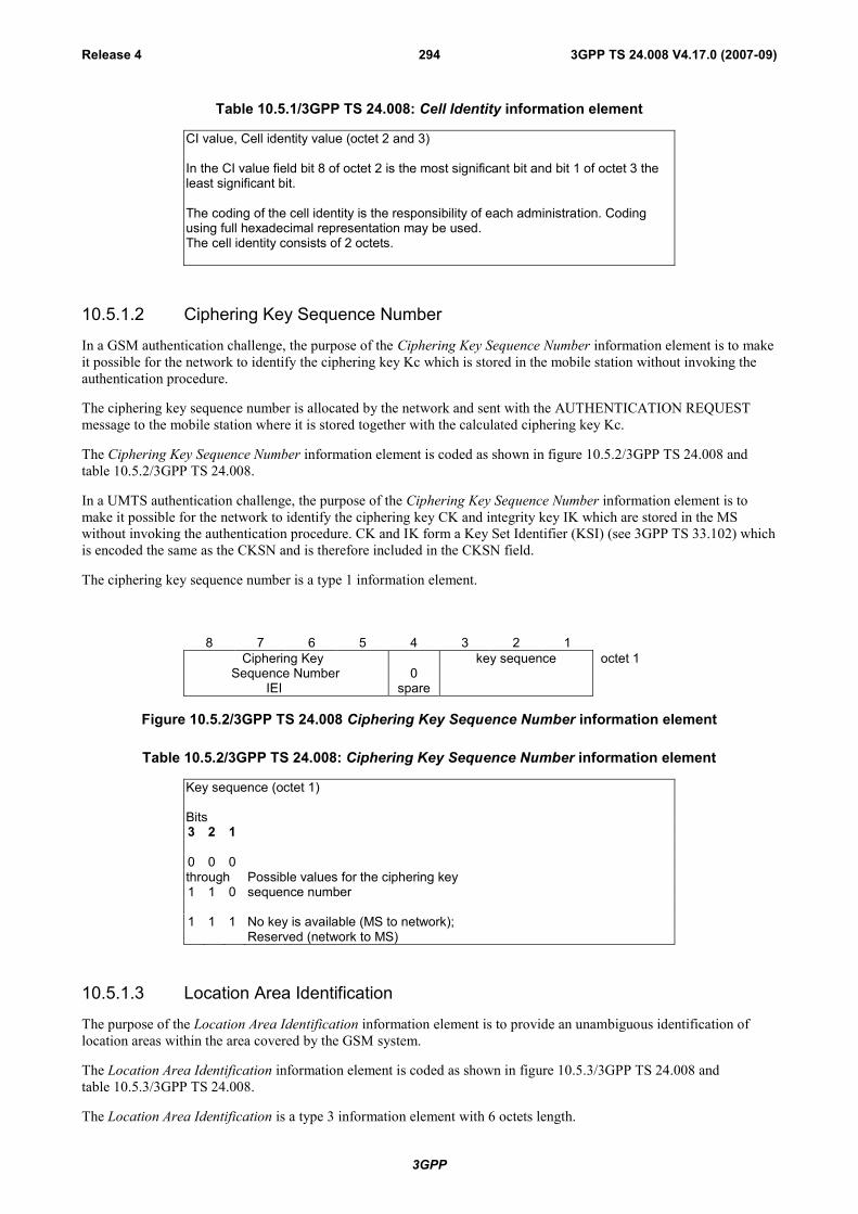
3GPP
3GPP TS 24.008 V4.17.0 (2007-09)Release 4 294
Table 10.5.1/3GPP TS 24.008: Cell Identity information element
CI value, Cell identity value (octet 2 and 3)
In the CI value field bit 8 of octet 2 is the most significant bit and bit 1 of octet 3 theleast significant bit.
The coding of the cell identity is the responsibility of each administration. Codingusing full hexadecimal representation may be used.The cell identity consists of 2 octets.
10.5.1.2 Ciphering Key Sequence Number
In a GSM authentication challenge, the purpose of the Ciphering Key Sequence Number information element is to makeit possible for the network to identify the ciphering key Kc which is stored in the mobile station without invoking theauthentication procedure.
The ciphering key sequence number is allocated by the network and sent with the AUTHENTICATION REQUESTmessage to the mobile station where it is stored together with the calculated ciphering key Kc.
The Ciphering Key Sequence Number information element is coded as shown in figure 10.5.2/3GPP TS 24.008 andtable 10.5.2/3GPP TS 24.008.
In a UMTS authentication challenge, the purpose of the Ciphering Key Sequence Number information element is tomake it possible for the network to identify the ciphering key CK and integrity key IK which are stored in the MSwithout invoking the authentication procedure. CK and IK form a Key Set Identifier (KSI) (see 3GPP TS 33.102) whichis encoded the same as the CKSN and is therefore included in the CKSN field.
The ciphering key sequence number is a type 1 information element.
8 7 6 5 4 3 2 1 Ciphering Key
Sequence Number IEI
0spare
key sequence octet 1
Figure 10.5.2/3GPP TS 24.008 Ciphering Key Sequence Number information element
Table 10.5.2/3GPP TS 24.008: Ciphering Key Sequence Number information element
Key sequence (octet 1)
Bits3 2 1
0 0 0through Possible values for the ciphering key1 1 0 sequence number
1 1 1 No key is available (MS to network);Reserved (network to MS)
10.5.1.3 Location Area Identification
The purpose of the Location Area Identification information element is to provide an unambiguous identification oflocation areas within the area covered by the GSM system.
The Location Area Identification information element is coded as shown in figure 10.5.3/3GPP TS 24.008 andtable 10.5.3/3GPP TS 24.008.
The Location Area Identification is a type 3 information element with 6 octets length.
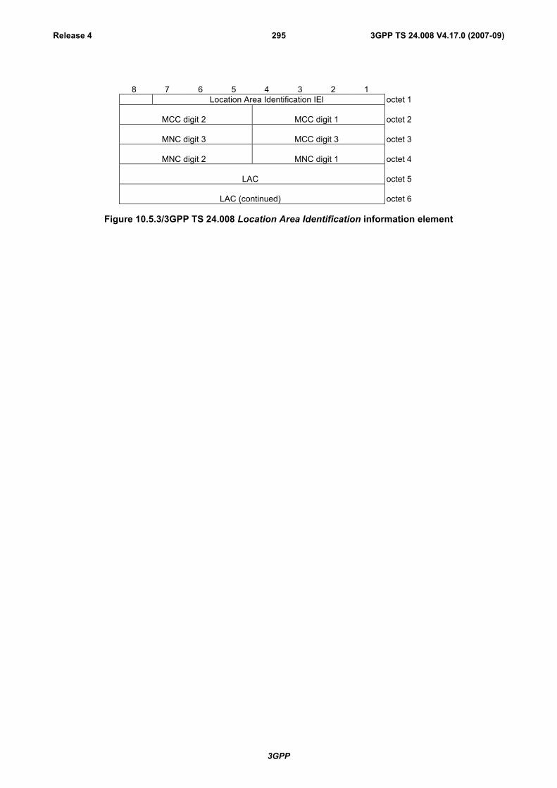
3GPP
3GPP TS 24.008 V4.17.0 (2007-09)Release 4 295
8 7 6 5 4 3 2 1Location Area Identification IEI octet 1
MCC digit 2 MCC digit 1 octet 2
MNC digit 3 MCC digit 3 octet 3
MNC digit 2 MNC digit 1 octet 4
LAC octet 5
LAC (continued) octet 6
Figure 10.5.3/3GPP TS 24.008 Location Area Identification information element

3GPP
3GPP TS 24.008 V4.17.0 (2007-09)Release 4 296
Table 10.5.3/3GPP TS 24.008: Location Area Identification information element
MCC, Mobile country code (octet 2 and 3)The MCC field is coded as in ITU-T Rec. E212, Annex A.
If the LAI is deleted the MCC and MNC shall take the value from the deleted LAI.
In abnormal cases, the MCC stored in the mobile station can contain elements notin the set {0, 1 ... 9}. In such cases the mobile station should transmit the storedvalues using full hexadecimal encoding. When receiving such an MCC, the networkshall treat the LAI as deleted.
MNC, Mobile network code (octet 3 bits 5 to 8, octet 4)The coding of this field is the responsibility of each administration but BCD codingshall be used. The MNC shall consist of 2 or 3 digits. For PCS 1900 for NA, Federalregulation mandates that a 3-digit MNC shall be used. However a network operatormay decide to use only two digits in the MNC in the LAI over the radio interface. Inthis case, bits 5 to 8 of octet 3 shall be coded as "1111". Mobile equipment shallaccept LAI coded in such a way.
NOTE 1: In earlier versions of this protocol, the possibility to use a one digit MNCin LAI was provided on the radio interface. However as this was not usedthis possibility has been deleted.
NOTE 2: In earlier versions of this protocol, bits 5 to 8 of octet 3 were coded as"1111". Mobile equipment compliant with these earlier versions of theprotocol may be unable to understand the 3-digit MNC format of the LAI,and therefore unable to register on a network broadcasting the LAI in thisformat.
In abnormal cases, the MNC stored in the mobile station can have:- digit 1 or 2 not in the set {0, 1 ... 9}, or- digit 3 not in the set {0, 1 ...9, F} hex.In such cases the mobile station shall transmit the stored values using fullhexadecimal encoding. When receiving such an MNC, the network shall treat theLAI as deleted.
The same handling shall apply for the network, if a 3-digit MNC is sent by themobile station to a network using only a 2-digit MNC.
LAC, Location area code (octet 5 and 6)In the LAC field bit 8 of octet 5 is the most significant bit and bit 1 of octet 6 theleast significant bit.The coding of the location area code is the responsibility of each administrationexcept that two values are used to mark the LAC, and hence the LAI, as deleted.Coding using full hexadecimal representation may be used. The location area codeconsists of 2 octets.If a LAI has to be deleted then all bits of the location area code shall be set to onewith the exception of the least significant bit which shall be set to zero. If a SIM isinserted in a Mobile Equipment with the location area code containing all zeros,then the Mobile Equipment shall recognise this LAC as part of a deleted LAI
10.5.1.4 Mobile Identity
The purpose of the Mobile Identity information element is to provide either the international mobile subscriber identity,IMSI, the temporary mobile subscriber identity, TMSI/P-TMSI, the international mobile equipment identity, IMEI orthe international mobile equipment identity together with the software version number, IMEISV.
The IMSI shall not exceed 15 digits, the TMSI/P-TMSI is 4 octets long, and the IMEI is composed of 15 digits, theIMEISV is 16 digits (see 3GPP TS 23.003 [10]).
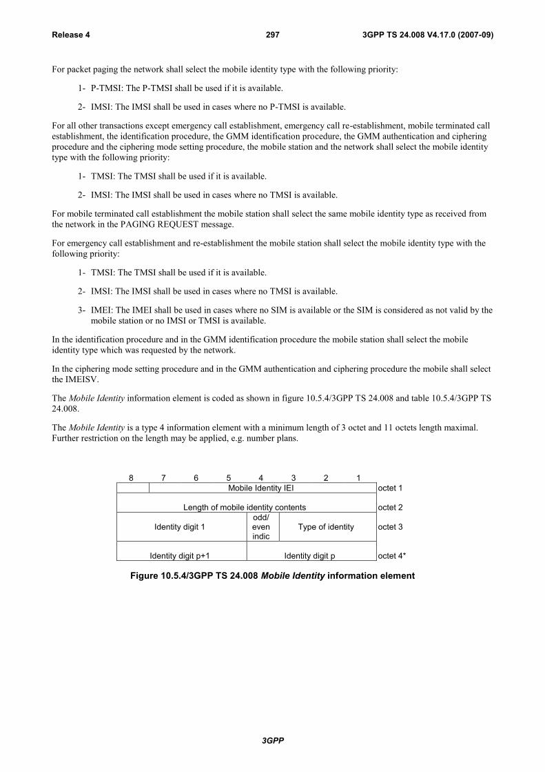
3GPP
3GPP TS 24.008 V4.17.0 (2007-09)Release 4 297
For packet paging the network shall select the mobile identity type with the following priority:
1- P-TMSI: The P-TMSI shall be used if it is available.
2- IMSI: The IMSI shall be used in cases where no P-TMSI is available.
For all other transactions except emergency call establishment, emergency call re-establishment, mobile terminated callestablishment, the identification procedure, the GMM identification procedure, the GMM authentication and cipheringprocedure and the ciphering mode setting procedure, the mobile station and the network shall select the mobile identitytype with the following priority:
1- TMSI: The TMSI shall be used if it is available.
2- IMSI: The IMSI shall be used in cases where no TMSI is available.
For mobile terminated call establishment the mobile station shall select the same mobile identity type as received fromthe network in the PAGING REQUEST message.
For emergency call establishment and re-establishment the mobile station shall select the mobile identity type with thefollowing priority:
1- TMSI: The TMSI shall be used if it is available.
2- IMSI: The IMSI shall be used in cases where no TMSI is available.
3- IMEI: The IMEI shall be used in cases where no SIM is available or the SIM is considered as not valid by themobile station or no IMSI or TMSI is available.
In the identification procedure and in the GMM identification procedure the mobile station shall select the mobileidentity type which was requested by the network.
In the ciphering mode setting procedure and in the GMM authentication and ciphering procedure the mobile shall selectthe IMEISV.
The Mobile Identity information element is coded as shown in figure 10.5.4/3GPP TS 24.008 and table 10.5.4/3GPP TS24.008.
The Mobile Identity is a type 4 information element with a minimum length of 3 octet and 11 octets length maximal.Further restriction on the length may be applied, e.g. number plans.
8 7 6 5 4 3 2 1Mobile Identity IEI octet 1
Length of mobile identity contents octet 2
Identity digit 1odd/evenindic
Type of identity octet 3
Identity digit p+1 Identity digit p octet 4*
Figure 10.5.4/3GPP TS 24.008 Mobile Identity information element

3GPP
3GPP TS 24.008 V4.17.0 (2007-09)Release 4 298
Table 10.5.4/3GPP TS 24.008: Mobile Identity information element
Type of identity (octet 3)Bits3 2 10 0 1 IMSI0 1 0 IMEI0 1 1 IMEISV1 0 0 TMSI/P-TMSI0 0 0 No Identity note 1)
All other values are reserved.
Odd/even indication (octet 3)Bit40 even number of identity digits and also when the TMSI/P-TMSI is used1 odd number of identity digits
Identity digits (octet 3 etc)
For the IMSI, IMEI and IMEISV this field is coded using BCD coding. If the numberof identity digits is even then bits 5 to 8 of the last octet shall be filled with an endmark coded as "1111".
If the mobile identity is the TMSI/P-TMSI then bits 5 to 8 of octet 3 are coded as"1111" and bit 8 of octet4 is the most significant bit and bit 1 of the last octet theleast significant bit. The coding of the TMSI/P-TMSI is left open for eachadministration.
NOTE: This can be used in the case when a fill paging message without any valid identity has to be sent on thepaging subchannel.
10.5.1.5 Mobile Station Classmark 1
The purpose of the Mobile Station Classmark 1 information element is to provide the network with informationconcerning aspects of high priority of the mobile station equipment. This affects the manner in which the networkhandles the operation of the mobile station. The Mobile Station Classmark information indicates general mobile stationcharacteristics and it shall therefore, except for fields explicitly indicated, be independent of the frequency band of thechannel it is sent on.
The Mobile Station Classmark 1 information element is coded as shown in figure 10.5.5/3GPP TS 24.008 andtable 10.5.5/3GPP TS 24.008.
The Mobile Station Classmark 1 is a type 3 information element with 2 octets length.
8 7 6 5 4 3 2 1Mobile Station Classmark 1 IEI octet 1
0spare
Revisionlevel
ESIND
A5/1 RF powercapability octet 2
Figure 10.5.5/3GPP TS 24.008 Mobile Station Classmark 1 information element
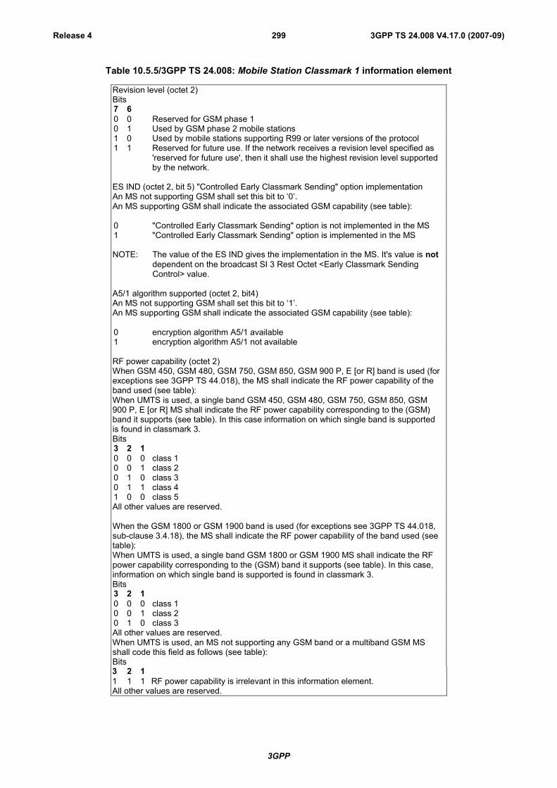
3GPP
3GPP TS 24.008 V4.17.0 (2007-09)Release 4 299
Table 10.5.5/3GPP TS 24.008: Mobile Station Classmark 1 information element
Revision level (octet 2)Bits7 60 0 Reserved for GSM phase 10 1 Used by GSM phase 2 mobile stations1 0 Used by mobile stations supporting R99 or later versions of the protocol1 1 Reserved for future use. If the network receives a revision level specified as
'reserved for future use', then it shall use the highest revision level supportedby the network.
ES IND (octet 2, bit 5) "Controlled Early Classmark Sending" option implementationAn MS not supporting GSM shall set this bit to ‘0’.An MS supporting GSM shall indicate the associated GSM capability (see table):
0 "Controlled Early Classmark Sending" option is not implemented in the MS1 "Controlled Early Classmark Sending" option is implemented in the MS
NOTE: The value of the ES IND gives the implementation in the MS. It's value is notdependent on the broadcast SI 3 Rest Octet <Early Classmark SendingControl> value.
A5/1 algorithm supported (octet 2, bit4)An MS not supporting GSM shall set this bit to ‘1’.An MS supporting GSM shall indicate the associated GSM capability (see table):
0 encryption algorithm A5/1 available1 encryption algorithm A5/1 not available
RF power capability (octet 2)When GSM 450, GSM 480, GSM 750, GSM 850, GSM 900 P, E [or R] band is used (forexceptions see 3GPP TS 44.018), the MS shall indicate the RF power capability of theband used (see table):When UMTS is used, a single band GSM 450, GSM 480, GSM 750, GSM 850, GSM900 P, E [or R] MS shall indicate the RF power capability corresponding to the (GSM)band it supports (see table). In this case information on which single band is supportedis found in classmark 3.Bits3 2 10 0 0 class 10 0 1 class 20 1 0 class 30 1 1 class 41 0 0 class 5All other values are reserved.
When the GSM 1800 or GSM 1900 band is used (for exceptions see 3GPP TS 44.018,sub-clause 3.4.18), the MS shall indicate the RF power capability of the band used (seetable):When UMTS is used, a single band GSM 1800 or GSM 1900 MS shall indicate the RFpower capability corresponding to the (GSM) band it supports (see table). In this case,information on which single band is supported is found in classmark 3.Bits3 2 10 0 0 class 10 0 1 class 20 1 0 class 3All other values are reserved.When UMTS is used, an MS not supporting any GSM band or a multiband GSM MSshall code this field as follows (see table):Bits3 2 11 1 1 RF power capability is irrelevant in this information element.All other values are reserved.

3GPP
3GPP TS 24.008 V4.17.0 (2007-09)Release 4 300
10.5.1.6 Mobile Station Classmark 2
The purpose of the Mobile Station Classmark 2 information element is to provide the network with informationconcerning aspects of both high and low priority of the mobile station equipment. This affects the manner in which thenetwork handles the operation of the mobile station. The Mobile Station Classmark information indicates generalmobile station characteristics and it shall therefore, except for fields explicitly indicated, be independent of thefrequency band of the channel it is sent on.
The Mobile Station Classmark 2 information element is coded as shown in figure 10.5.6/3GPP TS 24.008,table 10.5.6a/3GPP TS 24.008 and table 10.5.6b/3GPP TS 24.008.
The Mobile Station Classmark 2 is a type 4 information element with 5 octets length.
8 7 6 5 4 3 2 1Mobile station classmark 2 IEI octet 1
Length of mobile station classmark 2 contents octet 20
spareRevision
levelESIND
A5/1 RF powercapability octet 3
0spare
PScapa.
SS Screen.Indicator
SM capabi.
VBS VGCS FCoctet 4
CM3 0spare
LCSVACAP
UCS2 SoLSA CMSP A5/3 A5/2octet 5
NOTE: Owing to backward compatibility problems, bit 8 of octet 4 should not be used unless it is also checkedthat the bits 8, 7 and 6 of octet 3 are not "0 0 0".
Figure 10.5.6/3GPP TS 24.008 Mobile Station Classmark 2 information element
Table 10.5.6a/3GPP TS 24.008: Mobile Station Classmark 2 information element
Revision level (octet 3)Bits7 60 0 Reserved for GSM phase 10 1 Used by GSM phase 2 mobile stations1 0 Used by mobile stations supporting R99 or later versions of the protocol1 1 Reserved for future use. If the network receives a revision level specified as 'reserved
for future use', then it shall use the highest revision level supported by the network.
ES IND (octet 3, bit 5) "Controlled Early Classmark Sending" option implementationAN MS not supporting GSM shall set this bit to ‘0’.An MS supporting GSM shall indicate the associated GSM capability (see table):
0 "Controlled Early Classmark Sending" option is not implemented in the MS1 "Controlled Early Classmark Sending" option is implemented in the MS
NOTE: The value of the ES IND gives the implementation in the MS. It's value is notdependent on the broadcast SI 3 Rest Octet <Early Classmark Sending Control> value

3GPP
3GPP TS 24.008 V4.17.0 (2007-09)Release 4 301
Table 10.5.6a/3GPP TS 24.008: Mobile Station Classmark 2 information element
A5/1 algorithm supported (octet 3, bit 4)An MS not supporting GSM shall set this bit to ‘1’.An MS supporting GSM shall indicate the associated GSM capability (see table)
0 encryption algorithm A5/1 available1 encryption algorithm A5/1 not available
RF Power Capability (Octet 3)When GSM 450, GSM 480, GSM 750, GSM 850, GSM 900 P, E [or R] band is used (forexceptions see 3GPP TS 44.018), the MS shall indicate the RF power capability of the band used(see table).When UMTS is used, a single band GSM 450, GSM 480, GSM 750, GSM 850, GSM 900 P, E [orR] MS shall indicate the RF power capability corresponding to the (GSM) band it supports (seetable). In this case, information on which single band is supported is found in classmark 3.Bits3 2 10 0 0 class 10 0 1 class 20 1 0 class 30 1 1 class 41 0 0 class 5All other values are reserved.
When the GSM 1800 or GSM 1900 band is used (for exceptions see 3GPP TS 44.018) The MSshall indicate the RF power capability of the band used (see table).When UMTS is used, a single band GSM 1800 or GSM 1900 MS shall indicate the RF powercapability corresponding to the (GSM) band it supports (see table). In this case, information onwhich single band is supported is found in classmark 3Bits3 2 10 0 0 class 10 0 1 class 20 1 0 class 3All other values are reserved.
When UMTS is used, an MS not supporting any GSM band or a multiband GSM MS shall codethis field as follows (see table):Bits3 2 11 1 1 RF Power capability is irrelevant in this information elementAll other values are reserved.
PS capability (pseudo-synchronization capability) (octet 4)An MS not supporting GSM shall set this bit to ‘0’.An MS supporting GSM shall indicate the associated GSM capability (see table):Bit 70 PS capability not present1 PS capability present
SS Screening Indicator (octet 4)Bits6 50 0 defined in 3GPP TS 24.0800 1 defined in 3GPP TS 24.0801 0 defined in 3GPP TS 24.0801 1 defined in 3GPP TS 24.080
SM capability (MT SMS pt to pt capability) (octet 4)Bit 40 Mobile station does not support mobile terminated point to point SMS1 Mobile station supports mobile terminated point to point SMS

3GPP
3GPP TS 24.008 V4.17.0 (2007-09)Release 4 302
Table 10.5.6a/3GPP TS 24.008: Mobile Station Classmark 2 information element
VBS notification reception (octet 4)An MS not supporting GSM shall set this bit to ‘0’.An MS supporting GSM shall indicate the associated GSM capability (see table):Bit 30 no VBS capability or no notifications wanted1 VBS capability and notifications wanted
VGCS notification reception (octet 4)An MS not supporting GSM shall set this bit to ‘0’.An MS supporting GSM shall indicate the associated GSM capability (see table):Bit 20 no VGCS capability or no notifications wanted1 VGCS capability and notifications wanted
FC Frequency Capability (octet 4)When the GSM 400, or GSM 700, or GSM 850, or GSM 1800, or GSM 1900 band or UMTS isused (for exceptions see 3GPP TS 44.018), for definitions of frequency band see 3GPP TS45.005), this bit shall be sent with the value ‘0’.
Note: This bit conveys no information about support or non support of the E-GSM or R-GSMbands when GSM 400, GSM 700, GSM 850, GSM 1800, GSM 1900 band or UMTS is used.
When a GSM 900 band is used (for exceptions see 3GPP TS 44.018):Bit 10 The MS does not support the E-GSM or R-GSM band (For definition of frequency
bands see 3GPP TS 45.005 [33])1 The MS does support the E-GSM or R-GSM (For definition of frequency bands see
3GPP TS 45.005 [33])NOTE: For mobile station supporting the R-GSM band further information can be found in MS
Classmark 3.
CM3 (octet 5, bit 8)
0 The MS does not support any options that are indicated in CM31 The MS supports options that are indicated in classmark 3 IE
LCS VA capability (LCS value added location request notification capability) (octet 5,bit 6)
This information field indicates the support of the LCS value added location request notification viaCS domain as defined in 3GPP TS 23.271 [96].0 location request notification via CS domain not supported1 location request notification via CS domain supported
UCS2 treatment (octet 5, bit 5)
This information field indicates the likely treatment by the mobile station of UCS2 encodedcharacter strings. For backward compatibility reasons, if this field is not included, the value 0 shallbe assumed by the receiver.0 the ME has a preference for the default alphabet (defined in 3GPP TS 23.038 [8b])
over UCS2.1 the ME has no preference between the use of the default alphabet and the use of
UCS2.
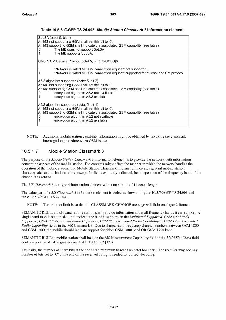
3GPP
3GPP TS 24.008 V4.17.0 (2007-09)Release 4 303
Table 10.5.6a/3GPP TS 24.008: Mobile Station Classmark 2 information element
SoLSA (octet 5, bit 4)An MS not supporting GSM shall set this bit to ‘0’.An MS supporting GSM shall indicate the associated GSM capability (see table):0 The ME does not support SoLSA.1 The ME supports SoLSA.
CMSP: CM Service Prompt (octet 5, bit 3) $(CCBS)$
0 "Network initiated MO CM connection request" not supported.1 "Network initiated MO CM connection request" supported for at least one CM protocol.
A5/3 algorithm supported (octet 5, bit 2)An MS not supporting GSM shall set this bit to ‘0’.An MS supporting GSM shall indicate the associated GSM capability (see table):0 encryption algorithm A5/3 not available1 encryption algorithm A5/3 available
A5/2 algorithm supported (octet 5, bit 1)An MS not supporting GSM shall set this bit to ‘0’.An MS supporting GSM shall indicate the associated GSM capability (see table):0 encryption algorithm A5/2 not available1 encryption algorithm A5/2 available
NOTE: Additional mobile station capability information might be obtained by invoking the classmarkinterrogation procedure when GSM is used.
10.5.1.7 Mobile Station Classmark 3
The purpose of the Mobile Station Classmark 3 information element is to provide the network with informationconcerning aspects of the mobile station. The contents might affect the manner in which the network handles theoperation of the mobile station. The Mobile Station Classmark information indicates general mobile stationcharacteristics and it shall therefore, except for fields explicitly indicated, be independent of the frequency band of thechannel it is sent on.
The MS Classmark 3 is a type 4 information element with a maximum of 14 octets length.
The value part of a MS Classmark 3 information element is coded as shown in figure 10.5.7/3GPP TS 24.008 andtable 10.5.7/3GPP TS 24.008.
NOTE: The 14 octet limit is so that the CLASSMARK CHANGE message will fit in one layer 2 frame.
SEMANTIC RULE: a multiband mobile station shall provide information about all frequency bands it can support. Asingle band mobile station shall not indicate the band it supports in the Multiband Supported, GSM 400 BandsSupported, GSM 750 Associated Radio Capability, GSM 850 Associated Radio Capability or GSM 1900 AssociatedRadio Capability fields in the MS Classmark 3. Due to shared radio frequency channel numbers between GSM 1800and GSM 1900, the mobile should indicate support for either GSM 1800 band OR GSM 1900 band.
SEMANTIC RULE: a mobile station shall include the MS Measurement Capability field if the Multi Slot Class fieldcontains a value of 19 or greater (see 3GPP TS 45.002 [32]).
Typically, the number of spare bits at the end is the minimum to reach an octet boundary. The receiver may add anynumber of bits set to "0" at the end of the received string if needed for correct decoding.

3GPP
3GPP TS 24.008 V4.17.0 (2007-09)Release 4 304
<Classmark 3 Value part> ::=< spare bit >{ < Multiband supported : { 000 } >
< A5 bits >| < Multiband supported : { 101 | 110 } >
< A5 bits >< Associated Radio Capability 2 : bit(4) >< Associated Radio Capability 1 : bit(4) >
| < Multiband supported : { 001 | 010 | 100 } >< A5 bits >< spare bit >(4)< Associated Radio Capability 1 : bit(4) > }
{ 0 | 1 < R Support > }{ 0 | 1 < Multi Slot Capability > }< UCS2 treatment: bit >< Extended Measurement Capability : bit >{ 0 | 1 < MS measurement capability > }{ 0 | 1 < MS Positioning Method Capability > }{ 0 | 1 < ECSD Multi Slot Capability > }{ 0 | 1 < 8-PSK Struct > }{ 0 | 1 < GSM 400 Bands Supported : { 01 | 10 | 11 } >
< GSM 400 Associated Radio Capability: bit(4) > }
{ 0 | 1 <GSM 850 Associated Radio Capability : bit(4) > }{ 0 | 1 <GSM 1900 Associated Radio Capability : bit(4) > }< UMTS FDD Radio Access Technology Capability : bit >< UMTS 3.84 Mcps TDD Radio Access Technology Capability : bit >< CDMA 2000 Radio Access Technology Capability : bit >
{ 0 | 1 < DTM GPRS Multi Slot Class : bit(2) >< Single Slot DTM : bit >{0 | 1< DTM EGPRS Multi Slot Class : bit(2) > } }
{ 0 | 1 < Single Band Support > } -- Release 4 starts here:{ 0 | 1 <GSM 750 Associated Radio Capability : bit(4)>}
< UMTS 1.28 Mcps TDD Radio Access Technology Capability : bit >< GERAN Feature Package 1 : bit >
{ 0 | 1 < Extended DTM GPRS Multi Slot Class : bit(2) >< Extended DTM EGPRS Multi Slot Class : bit(2) > }
< spare bit > ;
< A5 bits > ::=< A5/7 : bit > < A5/6 : bit > < A5/5 : bit > < A5/4 : bit > ;
<R Support>::=< R-GSM band Associated Radio Capability : bit(3) > ;
< Multi Slot Capability > ::=< Multi Slot Class : bit(5) > ;
< MS Measurement capability > ::=< SMS_VALUE : bit (4) >< SM_VALUE : bit (4) > ;
< MS Positioning Method Capability > ::=< MS Positioning Method : bit(5) > ;
< ECSD Multi Slot Capability > ::=< ECSD Multi Slot Class : bit(5) > ;
<8-PSK Struct> : :=< Modulation Capability : bit >{ 0 | 1 < 8-PSK RF Power Capability 1: bit(2) > }{ 0 | 1 < 8-PSK RF Power Capability 2: bit(2) > } ;

3GPP
3GPP TS 24.008 V4.17.0 (2007-09)Release 4 305
< Single Band Support > ::=< GSM Band : bit (4) > ;
Figure 10.5.7/3GPP TS 24.008 Mobile Station Classmark 3 information element

3GPP
3GPP TS 24.008 V4.17.0 (2007-09)Release 4 306
Table 10.5.7/3GPP TS 24.008: Mobile Station Classmark 3 information element
Multiband Supported (3 bit field)
Band 1 supportedBit 1
0 P-GSM not supported1 P-GSM supported
Band 2 supportedBit 2
0 E-GSM or R-GSM not supported1 E-GSM or R-GSM supported
Band 3 supportedBit 3
0 GSM 1800 not supported1 GSM 1800 supported
The indication of support of P-GSM band or E-GSM or R-GSM band is mutually exclusive.
When the 'Band 2 supported' bit indicates support of E-GSM or R-GSM, the presence of the <R Support> field,see below, indicates if the E-GSM or R-GSM band is supported.
In this version of the protocol, the sender indicates in this field either none, one or two of these 3 bandssupported.
For single band mobile station or a mobile station supporting none of the GSM 900 bands(P-GSM, E-GSM andR-GSM) and GSM 1800 bands, all bits are set to 0.
A5/4Bit 1
0 Encryption algorithm A5/4 not available1 Encryption algorithm A5/4 available
A5/5Bit 1
0 Encryption algorithm A5/5 not available1 Encryption algorithm A5/5 available
A5/6Bit 1
0 Encryption algorithm A5/6 not available1 Encryption algorithm A5/6 available
A5/70 Encryption algorithm A5/7 not available1 Encryption algorithm A5/7 available
Associated Radio capability 1 and 2 (4 bit fields)
If either of P-GSM or E-GSM or R-GSM is supported, the radio capability 1 field indicates the radio capability forP-GSM, E-GSM or R-GSM, and the radio capability 2 field indicates the radio capability for GSM 1800 ifsupported, and is spare otherwise.
If none of P-GSM or E-GSM or R-GSM are supported, the radio capability 1 field indicates the radio capabilityfor GSM 1800, and the radio capability 2 field is spare.
The radio capability contains the binary coding of the power class associated with the band indicated inmultiband support bits (see 3GPP TS 45.005 [33]).
(continued...)
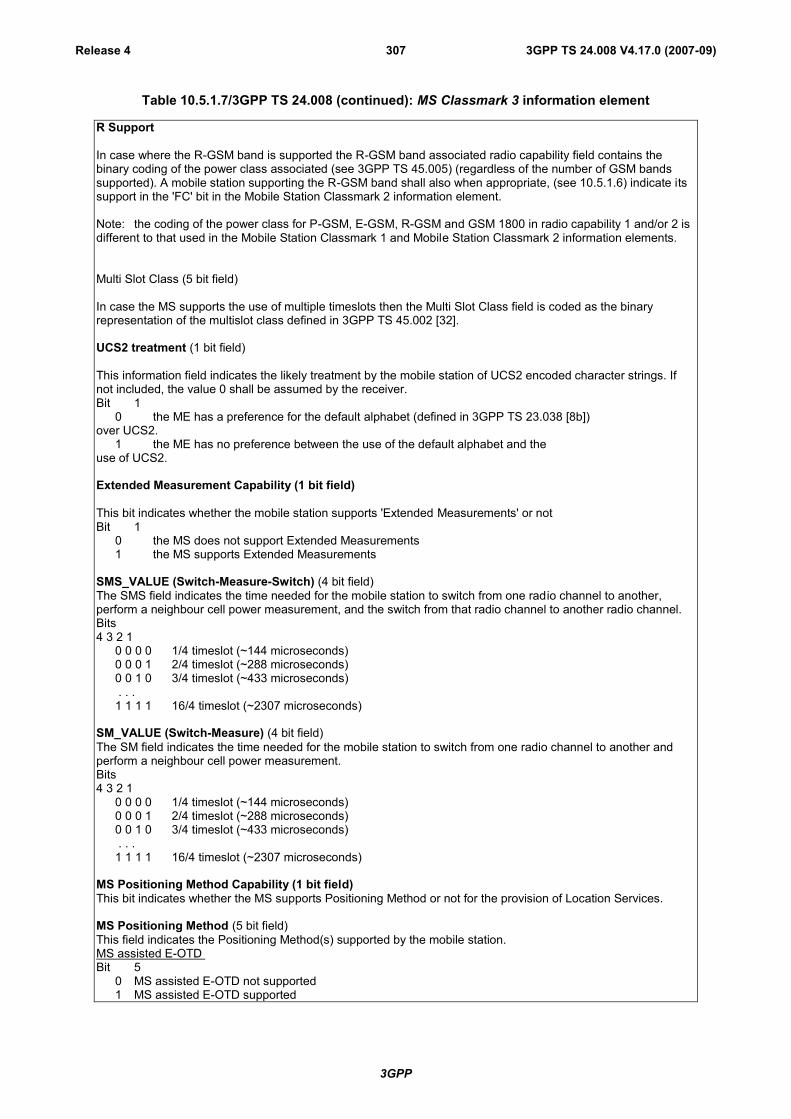
3GPP
3GPP TS 24.008 V4.17.0 (2007-09)Release 4 307
Table 10.5.1.7/3GPP TS 24.008 (continued): MS Classmark 3 information element
R Support
In case where the R-GSM band is supported the R-GSM band associated radio capability field contains thebinary coding of the power class associated (see 3GPP TS 45.005) (regardless of the number of GSM bandssupported). A mobile station supporting the R-GSM band shall also when appropriate, (see 10.5.1.6) indicate itssupport in the 'FC' bit in the Mobile Station Classmark 2 information element.
Note: the coding of the power class for P-GSM, E-GSM, R-GSM and GSM 1800 in radio capability 1 and/or 2 isdifferent to that used in the Mobile Station Classmark 1 and Mobile Station Classmark 2 information elements.
Multi Slot Class (5 bit field)
In case the MS supports the use of multiple timeslots then the Multi Slot Class field is coded as the binaryrepresentation of the multislot class defined in 3GPP TS 45.002 [32].
UCS2 treatment (1 bit field)
This information field indicates the likely treatment by the mobile station of UCS2 encoded character strings. Ifnot included, the value 0 shall be assumed by the receiver.Bit 1
0 the ME has a preference for the default alphabet (defined in 3GPP TS 23.038 [8b])over UCS2.
1 the ME has no preference between the use of the default alphabet and theuse of UCS2.
Extended Measurement Capability (1 bit field)
This bit indicates whether the mobile station supports 'Extended Measurements' or notBit 1
0 the MS does not support Extended Measurements1 the MS supports Extended Measurements
SMS_VALUE (Switch-Measure-Switch) (4 bit field)The SMS field indicates the time needed for the mobile station to switch from one radio channel to another,perform a neighbour cell power measurement, and the switch from that radio channel to another radio channel.Bits4 3 2 1
0 0 0 0 1/4 timeslot (~144 microseconds)0 0 0 1 2/4 timeslot (~288 microseconds)0 0 1 0 3/4 timeslot (~433 microseconds) . . .1 1 1 1 16/4 timeslot (~2307 microseconds)
SM_VALUE (Switch-Measure) (4 bit field)The SM field indicates the time needed for the mobile station to switch from one radio channel to another andperform a neighbour cell power measurement.Bits4 3 2 1
0 0 0 0 1/4 timeslot (~144 microseconds)0 0 0 1 2/4 timeslot (~288 microseconds)0 0 1 0 3/4 timeslot (~433 microseconds) . . .1 1 1 1 16/4 timeslot (~2307 microseconds)
MS Positioning Method Capability (1 bit field)This bit indicates whether the MS supports Positioning Method or not for the provision of Location Services.
MS Positioning Method (5 bit field)This field indicates the Positioning Method(s) supported by the mobile station.MS assisted E-OTDBit 5
0 MS assisted E-OTD not supported1 MS assisted E-OTD supported
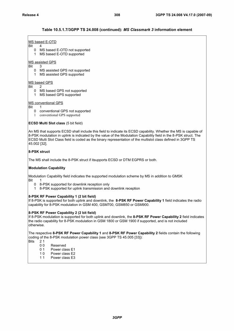
3GPP
3GPP TS 24.008 V4.17.0 (2007-09)Release 4 308
Table 10.5.1.7/3GPP TS 24.008 (continued): MS Classmark 3 information element
MS based E-OTDBit 4
0 MS based E-OTD not supported1 MS based E-OTD supported
MS assisted GPSBit 3
0 MS assisted GPS not supported1 MS assisted GPS supported
MS based GPSBit 2
0 MS based GPS not supported1 MS based GPS supported
MS conventional GPSBit 1
0 conventional GPS not supported1 conventional GPS supported
ECSD Multi Slot class (5 bit field)
An MS that supports ECSD shall include this field to indicate its ECSD capability. Whether the MS is capable of8-PSK modulation in uplink is indicated by the value of the Modulation Capability field in the 8-PSK struct. TheECSD Multi Slot Class field is coded as the binary representation of the multislot class defined in 3GPP TS45.002 [32].
8-PSK struct
The MS shall include the 8-PSK struct if itsupports ECSD or DTM EGPRS or both.
Modulation Capability
Modulation Capability field indicates the supported modulation scheme by MS in addition to GMSKBit 1
0 8-PSK supported for downlink reception only1 8-PSK supported for uplink transmission and downlink reception
8-PSK RF Power Capability 1 (2 bit field)If 8-PSK is supported for both uplink and downlink, the 8-PSK RF Power Capability 1 field indicates the radiocapability for 8-PSK modulation in GSM 400, GSM700, GSM850 or GSM900.
8-PSK RF Power Capability 2 (2 bit field)If 8-PSK modulation is supported for both uplink and downlink, the 8-PSK RF Power Capability 2 field indicatesthe radio capability for 8-PSK modulation in GSM 1800 or GSM 1900 if supported, and is not includedotherwise.
The respective 8-PSK RF Power Capability 1 and 8-PSK RF Power Capability 2 fields contain the followingcoding of the 8-PSK modulation power class (see 3GPP TS 45.005 [33]):Bits 2 1
0 0 Reserved0 1 Power class E11 0 Power class E21 1 Power class E3

3GPP
3GPP TS 24.008 V4.17.0 (2007-09)Release 4 309
Table 10.5.1.7/3GPP TS 24.008 (continued): MS Classmark 3 information element
GSM 400 Bands Supported (2 bit field)See the semantic rule for the sending of this field.Bits2 1
0 1 GSM 480 supported, GSM 450 not supported1 0 GSM 450 supported, GSM 480 not supported1 1 GSM 450 supported, GSM 480 supported
GSM 400 Associated Radio Capability (4 bit field)If either GSM 450 or GSM 480 or both is supported, the GSM 400 Associated Radio Capability field indicatesthe radio capability for GSM 450 and/or GSM 480.
The radio capability contains the binary coding of the power class associated with the band indicated in GSM400 Bands Supported bits (see 3GPP TS 45.005 [33]).
Note: the coding of the power class for GSM 450 and GSM 480 in GSM 400 Associated Radio Capability isdifferent to that used in the Mobile Station Classmark 1 and Mobile Station Classmark 2 information elements.
GSM 850 Associated Radio Capability (4 bit field)See the semantic rule for the sending of this field.This field indicates whether GSM 850 band is supported and its associated radio capability.
The radio capability contains the binary coding of the power class associated with the GSM 850 band (see3GPP TS 45.005 [33]).
Note: the coding of the power class for GSM 850 in GSM 850 Associated Radio Capability is different to thatused in the Mobile Station Classmark 1 and Mobile Station Classmark 2 information elements.
GSM 1900 Associated Radio Capability (4 bit field)See the semantic rule for the sending of this field.This field indicates whether GSM 1900 band is supported and its associated radio capability.
The radio capability contains the binary coding of the power class associated with the GSM 1900 band (see3GPP TS 45.005 [33]).
Note: the coding of the power class for GSM 1900 in GSM 1900 Associated Radio Capability is different to thatused in the Mobile Station Classmark 1 and Mobile Station Classmark 2 information elements.

3GPP
3GPP TS 24.008 V4.17.0 (2007-09)Release 4 310
Table 10.5.1.7/3GPP TS 24.008 (continued): MS Classmark 3 information element
UMTS FDD Radio Access Technology Capability (1 bit field)Bit 1
0 UMTS FDD not supported1 UMTS FDD supported
UMTS 3.84 Mcps TDD Radio Access Technology Capability (1 bit field)Bit 1
0 UMTS 3.84 Mcps TDD not supported1 UMTS 3.84 Mcps TDD supported
CDMA 2000 Radio Access Technology Capability (1 bit field)Bit 1
0 CDMA2000 not supported1 CDMA2000 supported
DTM GPRS Multi Slot Class (2 bit field)This field indicates the DTM GPRS multislot capabilities of the MS. It is coded as follows:
Bit 2 10 0 Unused. If received, the network shall interpret this as ‘01’0 1 Multislot class 5 supported1 0 Multislot class 9 supported1 1 Multislot class 11 supported
Single Slot DTM (1 bit field)This field indicates whether the MS supports single slot DTM operation (see 3GPP TS 43.055 [87]). It is codedas follows:
Bit 10 Single Slot DTM not supported1 Single Slot DTM supported
An MS indicating support for Extended DTM GPRS multislot class or Extended DTM EGPRS multislot classshall set this bit to ‘1’. The network may ignore the bit in this case.
DTM EGPRS Multi Slot Class (2 bit field)This field indicates the DTM EGPRS multislot capabilities of the MS. Whether the MS is capable of 8-PSKmodulation in uplink is indicated by the value of the Modulation Capability field in the 8-PSK struct. This fieldshall be included only if the mobile station supports DTM EGPRS. This field is coded as the DTM GPRS MultiSlot Class field.
Single Band SupportThis field shall be sent if the mobile station supports UMTS and one and only one GSM band with the exceptionof R-GSM; this field shall not be sent otherwise
GSM Band (4 bit field)Bits4 3 2 10 0 0 0 E-GSM is supported0 0 0 1 P-GSM is supported0 0 1 0 GSM 1800 is supported0 0 1 1 GSM 450 is supported0 1 0 0 GSM 480 is supported0 1 0 1 GSM 850 is supported0 1 1 0 GSM 1900 is supported0 1 1 1 GSM 750 is supportedAll other values are reserved for future use.
NOTE: When this field is received, the associated RF power capability is found in Classmark 1 or 2.
GSM 750 Associated Radio Capability (4 bit field)
See the semantic rule for the sending of this field.This field indicates whether GSM 750 band is supported and its associated radio capability.
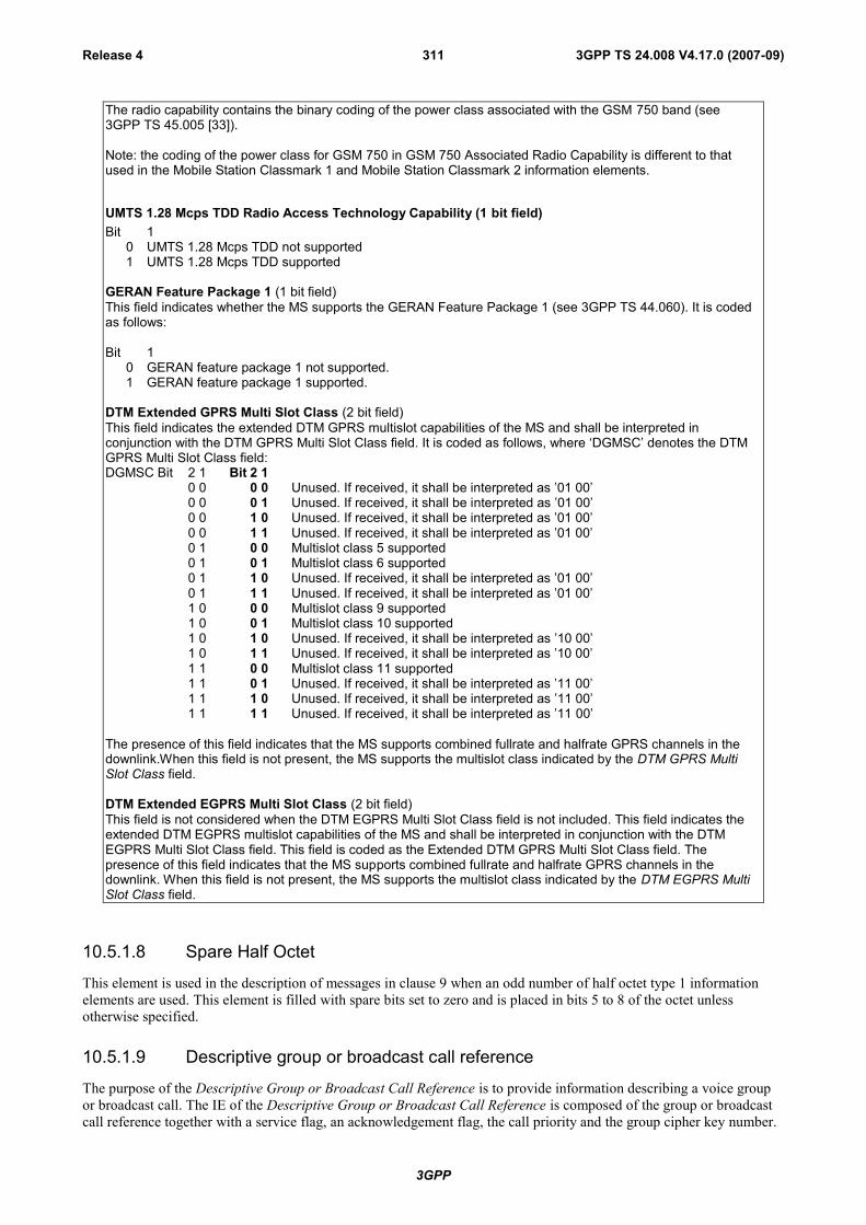
3GPP
3GPP TS 24.008 V4.17.0 (2007-09)Release 4 311
The radio capability contains the binary coding of the power class associated with the GSM 750 band (see3GPP TS 45.005 [33]).
Note: the coding of the power class for GSM 750 in GSM 750 Associated Radio Capability is different to thatused in the Mobile Station Classmark 1 and Mobile Station Classmark 2 information elements.
UMTS 1.28 Mcps TDD Radio Access Technology Capability (1 bit field)Bit 1
0 UMTS 1.28 Mcps TDD not supported1 UMTS 1.28 Mcps TDD supported
GERAN Feature Package 1 (1 bit field)This field indicates whether the MS supports the GERAN Feature Package 1 (see 3GPP TS 44.060). It is codedas follows:
Bit 10 GERAN feature package 1 not supported.1 GERAN feature package 1 supported.
DTM Extended GPRS Multi Slot Class (2 bit field)This field indicates the extended DTM GPRS multislot capabilities of the MS and shall be interpreted inconjunction with the DTM GPRS Multi Slot Class field. It is coded as follows, where ‘DGMSC’ denotes the DTMGPRS Multi Slot Class field:DGMSC Bit 2 1 Bit 2 1
0 0 0 0 Unused. If received, it shall be interpreted as ’01 00’0 0 0 1 Unused. If received, it shall be interpreted as ’01 00’0 0 1 0 Unused. If received, it shall be interpreted as ’01 00’0 0 1 1 Unused. If received, it shall be interpreted as ’01 00’0 1 0 0 Multislot class 5 supported0 1 0 1 Multislot class 6 supported0 1 1 0 Unused. If received, it shall be interpreted as ’01 00’0 1 1 1 Unused. If received, it shall be interpreted as ’01 00’1 0 0 0 Multislot class 9 supported1 0 0 1 Multislot class 10 supported1 0 1 0 Unused. If received, it shall be interpreted as ’10 00’1 0 1 1 Unused. If received, it shall be interpreted as ’10 00’1 1 0 0 Multislot class 11 supported1 1 0 1 Unused. If received, it shall be interpreted as ’11 00’1 1 1 0 Unused. If received, it shall be interpreted as ’11 00’1 1 1 1 Unused. If received, it shall be interpreted as ’11 00’
The presence of this field indicates that the MS supports combined fullrate and halfrate GPRS channels in thedownlink.When this field is not present, the MS supports the multislot class indicated by the DTM GPRS MultiSlot Class field.
DTM Extended EGPRS Multi Slot Class (2 bit field)This field is not considered when the DTM EGPRS Multi Slot Class field is not included. This field indicates theextended DTM EGPRS multislot capabilities of the MS and shall be interpreted in conjunction with the DTMEGPRS Multi Slot Class field. This field is coded as the Extended DTM GPRS Multi Slot Class field. Thepresence of this field indicates that the MS supports combined fullrate and halfrate GPRS channels in thedownlink. When this field is not present, the MS supports the multislot class indicated by the DTM EGPRS MultiSlot Class field.
10.5.1.8 Spare Half Octet
This element is used in the description of messages in clause 9 when an odd number of half octet type 1 informationelements are used. This element is filled with spare bits set to zero and is placed in bits 5 to 8 of the octet unlessotherwise specified.
10.5.1.9 Descriptive group or broadcast call reference
The purpose of the Descriptive Group or Broadcast Call Reference is to provide information describing a voice groupor broadcast call. The IE of the Descriptive Group or Broadcast Call Reference is composed of the group or broadcastcall reference together with a service flag, an acknowledgement flag, the call priority and the group cipher key number.
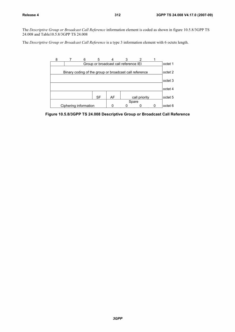
3GPP
3GPP TS 24.008 V4.17.0 (2007-09)Release 4 312
The Descriptive Group or Broadcast Call Reference information element is coded as shown in figure 10.5.8/3GPP TS24.008 and Table10.5.8/3GPP TS 24.008
The Descriptive Group or Broadcast Call Reference is a type 3 information element with 6 octets length.
8 7 6 5 4 3 2 1Group or broadcast call reference IEI octet 1
Binary coding of the group or broadcast call reference octet 2
octet 3
octet 4
SF AF call priority octet 5Spare
Ciphering information 0 0 0 0 octet 6
Figure 10.5.8/3GPP TS 24.008 Descriptive Group or Broadcast Call Reference

3GPP
3GPP TS 24.008 V4.17.0 (2007-09)Release 4 313
Table 10.5.8/3GPP TS 24.008 Descriptive Group or Broadcast Call Reference
Binary code of the group or broadcast call referenceThe length of the binary code has 27 bits which is encoded in the octet 2, 3, 4 andBits 8,7,6 (octet 5).The highest bit of the BC is the bit 8 in the octet 2 and the lowest bit is allocated inthe bit 6 in the octet 5. (see also 3GPP TS 23.003 [10])SF Service flag (octet 5)Bit50 VBS (broadcast call reference)1 VGCS (group call reference)
AF Acknowledgement flag (octet 5), network to MS direction:Bit40 acknowledgement is not required1 acknowledgement is required
Call priority (octet 5)Bit3 2 10 0 0 no priority applied0 0 1 call priority level 40 1 0 call priority level 30 1 1 call priority level 21 0 0 call priority level 11 0 1 call priority level 01 1 0 call priority level B1 1 1 call priority level A
Ciphering information (octet 6)Bit8 7 6 50 0 0 0 no ciphering0 0 0 1 ciphering with cipher key number 10 0 1 0 ciphering with cipher key number 20 0 1 1 ciphering with cipher key number 30 1 0 0 ciphering with cipher key number 40 1 0 1 ciphering with cipher key number 50 1 1 0 ciphering with cipher key number 60 1 1 1 ciphering with cipher key number 71 0 0 0 ciphering with cipher key number 81 0 0 1 ciphering with cipher key number 91 0 1 0 ciphering with cipher key number A1 0 1 1 ciphering with cipher key number B1 1 0 0 ciphering with cipher key number C1 1 0 1 ciphering with cipher key number D1 1 1 0 ciphering with cipher key number E1 1 1 1 ciphering with cipher key number F
AF Acknowledgement flag (octet 5), MS to network direction:Bit 4 is spare and shall be set to "0".
Call priority (octet 5)Bits 1 to 3 are spare and shall be set to "0".
Ciphering information (octet 6)Bits 5 to 8 are spare and shall be set to "0".
10.5.1.10 Group Cipher Key Number
The purpose of the Group Cipher Key Number is to provide information on the group cipher key to be used forciphering and deciphering by the mobile station.
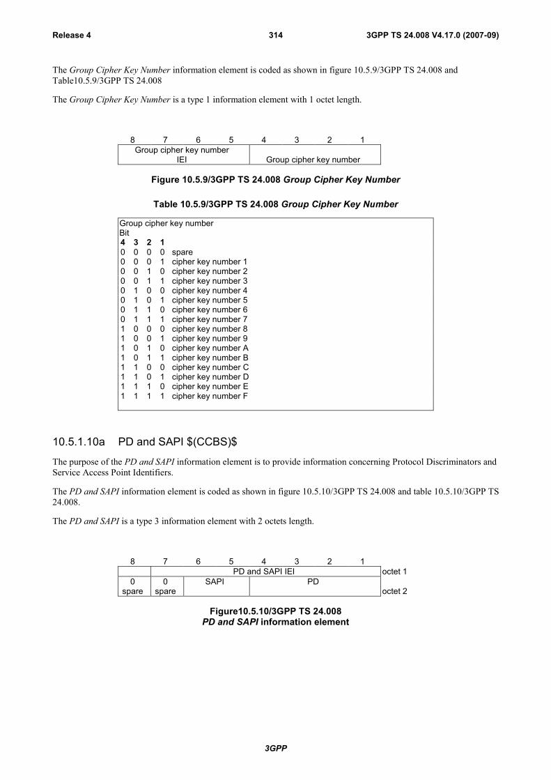
3GPP
3GPP TS 24.008 V4.17.0 (2007-09)Release 4 314
The Group Cipher Key Number information element is coded as shown in figure 10.5.9/3GPP TS 24.008 andTable10.5.9/3GPP TS 24.008
The Group Cipher Key Number is a type 1 information element with 1 octet length.
8 7 6 5 4 3 2 1Group cipher key number
IEI Group cipher key number
Figure 10.5.9/3GPP TS 24.008 Group Cipher Key Number
Table 10.5.9/3GPP TS 24.008 Group Cipher Key Number
Group cipher key numberBit4 3 2 10 0 0 0 spare0 0 0 1 cipher key number 10 0 1 0 cipher key number 20 0 1 1 cipher key number 30 1 0 0 cipher key number 40 1 0 1 cipher key number 50 1 1 0 cipher key number 60 1 1 1 cipher key number 71 0 0 0 cipher key number 81 0 0 1 cipher key number 91 0 1 0 cipher key number A1 0 1 1 cipher key number B1 1 0 0 cipher key number C1 1 0 1 cipher key number D1 1 1 0 cipher key number E1 1 1 1 cipher key number F
10.5.1.10a PD and SAPI $(CCBS)$
The purpose of the PD and SAPI information element is to provide information concerning Protocol Discriminators andService Access Point Identifiers.
The PD and SAPI information element is coded as shown in figure 10.5.10/3GPP TS 24.008 and table 10.5.10/3GPP TS24.008.
The PD and SAPI is a type 3 information element with 2 octets length.
8 7 6 5 4 3 2 1PD and SAPI IEI octet 1
0spare
0spare
SAPI PDoctet 2
Figure10.5.10/3GPP TS 24.008PD and SAPI information element
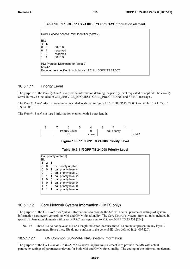
3GPP
3GPP TS 24.008 V4.17.0 (2007-09)Release 4 315
Table 10.5.1.10/3GPP TS 24.008: PD and SAPI information element
SAPI: Service Access Point Identifier (octet 2)
Bits6 50 0 SAPI 00 1 reserved1 0 reserved1 1 SAPI 3
PD: Protocol Discriminator (octet 2)bits 4-1Encoded as specified in subclause 11.2.1 of 3GPP TS 24.007.
10.5.1.11 Priority Level
The purpose of the Priority Level is to provide information defining the priority level requested or applied. The PriorityLevel IE may be included in CM_SERVICE_REQUEST, CALL_PROCEEDING and SETUP messages.
The Priority Level information element is coded as shown in figure 10.5.11/3GPP TS 24.008 and table 10.5.11/3GPPTS 24.008.
The Priority Level is a type 1 information element with 1 octet length.
8 7 6 5 4 3 2 1Priority Level
IEI0
sparecall priority
octet 1
Figure 10.5.11/3GPP TS 24.008 Priority Level
Table 10.5.11/3GPP TS 24.008 Priority Level
Call priority (octet 1)Bit3 2 10 0 0 no priority applied0 0 1 call priority level 40 1 0 call priority level 30 1 1 call priority level 21 0 0 call priority level 11 0 1 call priority level 01 1 0 call priority level B1 1 1 call priority level A
10.5.1.12 Core Network System Information (UMTS only)
The purpose of the Core Network System Information is to provide the MS with actual parameter settings of systeminformation parameters controlling MM and GMM functionality. The Core Network system information is included inspecific information elements within some RRC messages sent to MS, see 3GPP TS 25.331 [23c].
NOTE: These IEs do not have an IEI or a length indicator, because these IEs are never present in any layer 3messages, Hence these IEs do not conform to the general IE rules defined in 24.007 [20].
10.5.1.12.1 CN Common GSM-MAP NAS system information
The purpose of the CN Common GSM-MAP NAS system information element is to provide the MS with actualparameter settings of parameters relevant for both MM and GMM functionality. The coding of the information element

3GPP
3GPP TS 24.008 V4.17.0 (2007-09)Release 4 316
identifier and length information is defined in the 3GPP TS 25.331 [23c]. Only the coding of the content is in the scopeof the present document.
The content of the CN common GSM-MAP NAS system information element is coded as shown infigure 10.5.1.12.1/3GPP TS 24.008 and table 10.5.1.12.1/3GPP TS 24.008.
The length of this element content is two octets. The MS shall ignore any additional octets received.
8 7 6 5 4 3 2 1LAC octet 1
octet 2
Figure 10.5.1.12.1/3GPP TS 24.008 Common system information element
Table 10.5.1.12.1/3GPP TS 24.008: Common system information element
LAC, Location Area Code (2 octet field)This field is the binary representation of the Location Area Code, see 3GPP TS 23.003. The LAC fieldconsists of 16 bits. Bit 8 in octet 1 is the most significant bit and bit 1 in octet 2 is the least significant bit.
10.5.1.12.2 CS domain specific system information
The purpose of the CN domain specific GSM-MAP NAS system information element, when used for the CS domain, isto provide the MS with actual parameter settings of parameters relevant only for MM functionality. The coding of theinformation element identifier and length information is defined in the 3GPP TS 25.331 [23c]. Only the coding of thecontent is in the scope of the present document.
For CS domain, the content of the CN domain specific GSM-MAP NAS system information element is coded as shownin figure 10.5.1.12.2/3GPP TS 24.008 and table 10.5.1.12.2/3GPP TS 24.008. The length of this element content is twooctets. The MS shall ignore any additional octets received.
8 7 6 5 4 3 2 1T3212 octet 1
Spare ATT octet 2
Figure 10.5.1.12.2/3GPP TS 24.008 CS domain specific system information element
Table 10.5.1.12.2/3GPP TS 24.008: CS domain specific system information element
T3212 timeout value (1 octet field)The T3212 timeout field is coded as the binary representation of the timeout value for periodic updating indecihours. Bit 8 in octet 1 is the most significant bit and bit 1 in octet 1 is the least significant bit.Range: 1 to 255The value 0 is used for infinite timeout value i.e. periodic updating shall not be used
ATT, Attach-detach allowed (1 bit field):Bit 1
0 MSs shall not apply IMSI attach and detach procedure.1 MSs shall apply IMSI attach and detach procedure
The bits 2 – 8 of octet 2 are spare and shall be coded all zeros.
10.5.1.12.3 PS domain specific system information
The purpose of the CN domain specific GSM-MAP NAS system information element, when used for the PS domain, is toprovide the MS with actual parameter settings of parameters relevant only for GMM functionality. The coding of theinformation element identifier and length information is defined in the 3GPP TS 25.331. Only the coding of the contentis in the scope of the present document.
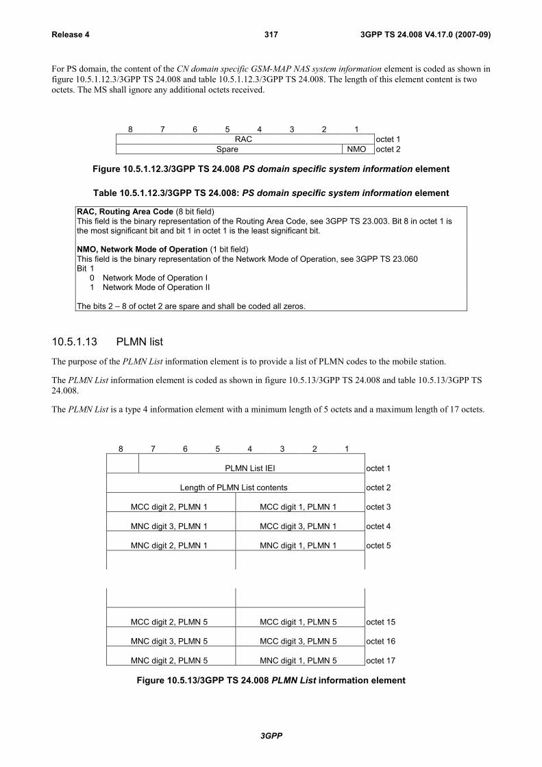
3GPP
3GPP TS 24.008 V4.17.0 (2007-09)Release 4 317
For PS domain, the content of the CN domain specific GSM-MAP NAS system information element is coded as shown infigure 10.5.1.12.3/3GPP TS 24.008 and table 10.5.1.12.3/3GPP TS 24.008. The length of this element content is twooctets. The MS shall ignore any additional octets received.
8 7 6 5 4 3 2 1RAC octet 1
Spare NMO octet 2
Figure 10.5.1.12.3/3GPP TS 24.008 PS domain specific system information element
Table 10.5.1.12.3/3GPP TS 24.008: PS domain specific system information element
RAC, Routing Area Code (8 bit field)This field is the binary representation of the Routing Area Code, see 3GPP TS 23.003. Bit 8 in octet 1 isthe most significant bit and bit 1 in octet 1 is the least significant bit.
NMO, Network Mode of Operation (1 bit field)This field is the binary representation of the Network Mode of Operation, see 3GPP TS 23.060Bit 1
0 Network Mode of Operation I1 Network Mode of Operation II
The bits 2 – 8 of octet 2 are spare and shall be coded all zeros.
10.5.1.13 PLMN list
The purpose of the PLMN List information element is to provide a list of PLMN codes to the mobile station.
The PLMN List information element is coded as shown in figure 10.5.13/3GPP TS 24.008 and table 10.5.13/3GPP TS24.008.
The PLMN List is a type 4 information element with a minimum length of 5 octets and a maximum length of 17 octets.
8 7 6 5 4 3 2 1
PLMN List IEI octet 1
Length of PLMN List contents octet 2
MCC digit 2, PLMN 1 MCC digit 1, PLMN 1 octet 3
MNC digit 3, PLMN 1 MCC digit 3, PLMN 1 octet 4
MNC digit 2, PLMN 1 MNC digit 1, PLMN 1 octet 5
MCC digit 2, PLMN 5 MCC digit 1, PLMN 5 octet 15
MNC digit 3, PLMN 5 MCC digit 3, PLMN 5 octet 16
MNC digit 2, PLMN 5 MNC digit 1, PLMN 5 octet 17
Figure 10.5.13/3GPP TS 24.008 PLMN List information element

3GPP
3GPP TS 24.008 V4.17.0 (2007-09)Release 4 318
Table 10.5.13/3GPP TS 24.008: PLMN List information element
MCC, Mobile country code (octet 3, octet 4 bits 1 to 4)The MCC field is coded as in ITU-T Rec. E212, Annex A.
MNC, Mobile network code (octet 5, octet 4 bits 5 to 8).The coding of this field is the responsibility of each administration but BCD codingshall be used. The MNC shall consist of 2 or 3 digits. For PCS 1900 for NA, Federalregulation mandates that a 3-digit MNC shall be used. However a network operatormay decide to use only two digits in the MNC over the radio interface. In this case,bits 5 to 8 of octet 4 shall be coded as "1111". Mobile equipment shall accept MNCcoded in such a way.
10.5.2 Radio Resource management information elements.See 3GPP TS 44.018 [84].
10.5.3 Mobility management information elements.
10.5.3.1 Authentication parameter RAND
The purpose of the Authentication Parameter RAND information element is to provide the mobile station with a non-predictable number to be used to calculate the authentication response signature SRES and the ciphering key Kc (for aGSM authentication challenge), or the response RES and both the ciphering key CK and integrity key IK (for a UMTSauthentication challenge).
The Authentication Parameter RAND information element is coded as shown in figure 10.5.75/3GPP TS 24.008 andtable 10.5.89/3GPP TS 24.008.
The Authentication Parameter RAND is a type 3 information element with 17 octets length.
8 7 6 5 4 3 2 1Authentication parameter RAND IEI octet 1
RAND value octet 2
octet 17
Figure 10.5.75/3GPP TS 24.008 Authentication Parameter RAND information element
Table 10.5.89/3GPP TS 24.008: Authentication Parameter RAND information element
RAND value (octet 2, 3,... and 17)The RAND value consists of 128 bits. Bit 8 of octet 2 is the most significant bit while bit 1 of octet17 is the least significant bit.
10.5.3.1.1 Authentication Parameter AUTN (UMTS authentication challenge only)
The purpose of the Authentication Parameter AUTN information element is to provide the MS with a means ofauthenticating the network.
The Authentication Parameter AUTN information element is coded as shown in figure 10.5.75.1/3GPP TS 24.008 andtable 10.5.89.1/3GPP TS 24.008.

3GPP
3GPP TS 24.008 V4.17.0 (2007-09)Release 4 319
The Authentication Parameter AUTN is a type 4 information element with a length of 18 octets.
8 7 6 5 4 3 2 1Authentication Parameter AUTN IEI octet 1
Length of AUTN contents octet 2octet 3
AUTN
octet 18
Figure 10.5.75.1/3GPP TS 24.008 Authentication Parameter AUTN information element (UMTSauthentication challenge only)
Table 10.5.89.1/3GPP TS 24.008 Authentication Parameter AUTN information element (UMTSauthentication challenge only)
AUTN value (octets 3 to 18)The AUTN consists of (SQN xor AK)||AMF||MAC
=48+16+64 bits(see 3GPP TS 33.102)
10.5.3.2 Authentication Response parameter
The purpose of the authentication response parameter information element is to provide the network with theauthentication response calculated in the SIM.
The Authentication Parameter SRES information element is coded as shown in figure 10.5.76/3GPP TS 24.008 andtables 10.5.90 a & b /3GPP TS 24.008.
The Authentication Response Parameter is a type 3 information element with 5 octets length. In a GSM authenticationchallenge, the response calculated in the SIM (SRES) is 4 bytes in length, and is placed in the Authentication ResponseParameter information element.
In a UMTS authentication challenge, the response calculated in the SIM (RES) may be up to 16 octets in length. The 4most significant octets shall be included in the Authentication Response Parameter information element. The remainingpart of the RES shall be included in the Authentication Response Parameter (extension) IE (see subclause 10.5.3.2.1)
8 7 6 5 4 3 2 1Authentication Response parameter IEI octet 1
SRES value or most significant4 octets of RES
:
octet 2
:octet 5
Figure 10.5.76/3GPP TS 24.008 Authentication Response Parameter information element
Table 10.5.90a/3GPP TS 24.008: Authentication Response Parameter information element(SRES) (GSM only)
SRES value (octet 2, 3, 4 and 5)The SRES value consists of 32 bits. Bit 8 of octet 2 is the most significant bit while bit 1 of octet 5is the least significant bit.

3GPP
3GPP TS 24.008 V4.17.0 (2007-09)Release 4 320
Table 10.5.90b/3GPP TS 24.008: Authentication Response Parameter information element (RES)(UMTS only)
RES value (octet 2, 3, 4 and 5)This contains the most significant 4 octets of RESIf RES>4 octets, the remaining octets of RES shall appear in the Authentication ResponseParameter (extension) IE (see subclause 10.5.3.2.1)
10.5.3.2.1 Authentication Response Parameter (extension) (UMTS authentication challengeonly)
This IE is included if the authentication response parameter RES is longer than 4 octets (UMTS only) and thereforedoes not fit in the Authentication Response Parameter field (see 10.5.3.2).
The Authentication Response parameter (extension) IE is coded as shown in figure 10.5.76.1/3GPP TS 24.008 and table10.5.90.1/3GPP TS 24.008.
The Authentication Response parameter (extension) IE is a type 4 information element with a minimum length of 3octets and a maximum length of 14 octets.
8 7 6 5 4 3 2 1Authentication Response (extension) IEI octet 1
Length of Authentication Response contents octet 2RES (all but 4 most significant octets)
:octet 3
:
octet 14
Figure 10.5.76.1/3GPP TS 24.008 Authentication Response Parameter (extension) informationelement (UMTS only)
Table 10.5.90.1/3GPP TS 24.008: Authentication Response Parameter (extension) information element(RES)
RES (extension) value (octet 3 to 14)
This contains all but the 4 most significant octets of RES
10.5.3.2.2 Authentication Failure parameter (UMTS authentication challenge only)
The purpose of the Authentication Failure parameter information element is to provide the network with the necessaryinformation to begin a re-authentication procedure (see 3GPP TS 33.102) in the case of a 'Synch failure', following aUMTS authentication challenge.
The Authentication Failure parameter IE is coded as shown in figure 10.5.76.2/3GPP TS 24.008 and table10.5.90.2/3GPP TS 24.008.
The Authentication Failure parameter IE is a type 4 information element with a length of 16 octets.

3GPP
3GPP TS 24.008 V4.17.0 (2007-09)Release 4 321
8 7 6 5 4 3 2 1Authentication Failure parameter IEI octet 1
Length ofAuthentication Failure parameter contents octet 2Authentication Failure parameter
:octet 3
:
octet 16
Figure 10.5.76.2/3GPP TS 24.008 Authentication Failure parameter information element (UMTSauthentication challenge only)
Table 10.5.90.2/3GPP TS 24.008: Authentication Failure parameter information element
Authentication Failure parameter value (octet 3 to 16)
This contains AUTS (see 3GPP TS 33.102)
10.5.3.3 CM service type
The purpose of the CM Service Type information element is to specify which service is requested from the network.
The CM Service Type information element is coded as shown in figure 10.5.77/3GPP TS 24.008 andtable 10.5.91/3GPP TS 24.008.
The CM Service Type is a type 1 information element.
8 7 6 5 4 3 2 1CM service type IEI service type octet 1
Figure 10.5.77/3GPP TS 24.008 CM Service Type information element
Table 10.5.91/3GPP TS 24.008: CM Service Type information element
Service type (octet 1)Bits4 3 2 10 0 0 1 Mobile originating call establishment or packet mode connection
establishment0 0 1 0 Emergency call establishment0 1 0 0 Short message service1 0 0 0 Supplementary service activation1 0 0 1 Voice group call establishment1 0 1 0 Voice broadcast call establishment1 0 1 1 Location Services (NOTE)
All other values are reserved.NOTE: this service type shall only be used by a type A LMU if the MM
connection was requested for the transmission of LCS signallingmessages specified in 3GPP TS 44.071 [23a].
10.5.3.4 Identity type
The purpose of the Identity Type information element is to specify which identity is requested.
The Identity Type information element is coded as shown in figure 10.5.78/3GPP TS 24.008 and table 10.5.92/3GPP TS24.008.

3GPP
3GPP TS 24.008 V4.17.0 (2007-09)Release 4 322
The Identity Type is a type 1 information element.
8 7 6 5 4 3 2 1Identity type IEI 0
sparetype of identity octet 1
Figure 10.5.78/3GPP TS 24.008 Identity Type information element
Table 10.5.92/3GPP TS 24.008: Identity Type information element
Type of identity (octet 1)Bits3 2 10 0 1 IMSI0 1 0 IMEI0 1 1 IMEISV1 0 0 TMSI
All other values are reserved.
10.5.3.5 Location updating type
The purpose of the Location Updating Type information element is to indicate whether a normal updating, a periodicupdating or an IMSI attach is wanted. It may also indicate that a follow-on request has been received from the mobilestation CM layer.
The Location Updating Type information element is coded as shown in figure 10.5.79/3GPP TS 24.008 andtable 10.5.93/3GPP TS 24.008.
The Location Updating Type is a type 1 information element.
8 7 6 5 4 3 2 1Location updating
type IEIFOR 0
spareLUT octet 1
Figure 10.5.79/3GPP TS 24.008 Location Updating Type information element
Table 10.5.93/3GPP TS 24.008: Location Updating Type information element
LUT (octet 1)Bits2 10 0 Normal location updating0 1 Periodic updating1 0 IMSI attach1 1 Reserved
FOR (octet 1)The Follow-On Request bit (FOR) is coded as follows:Bits40 No follow-on request pending1 Follow-on request pending
10.5.3.5a Network Name
The purpose of this information element is to pass a text string to the mobile station.
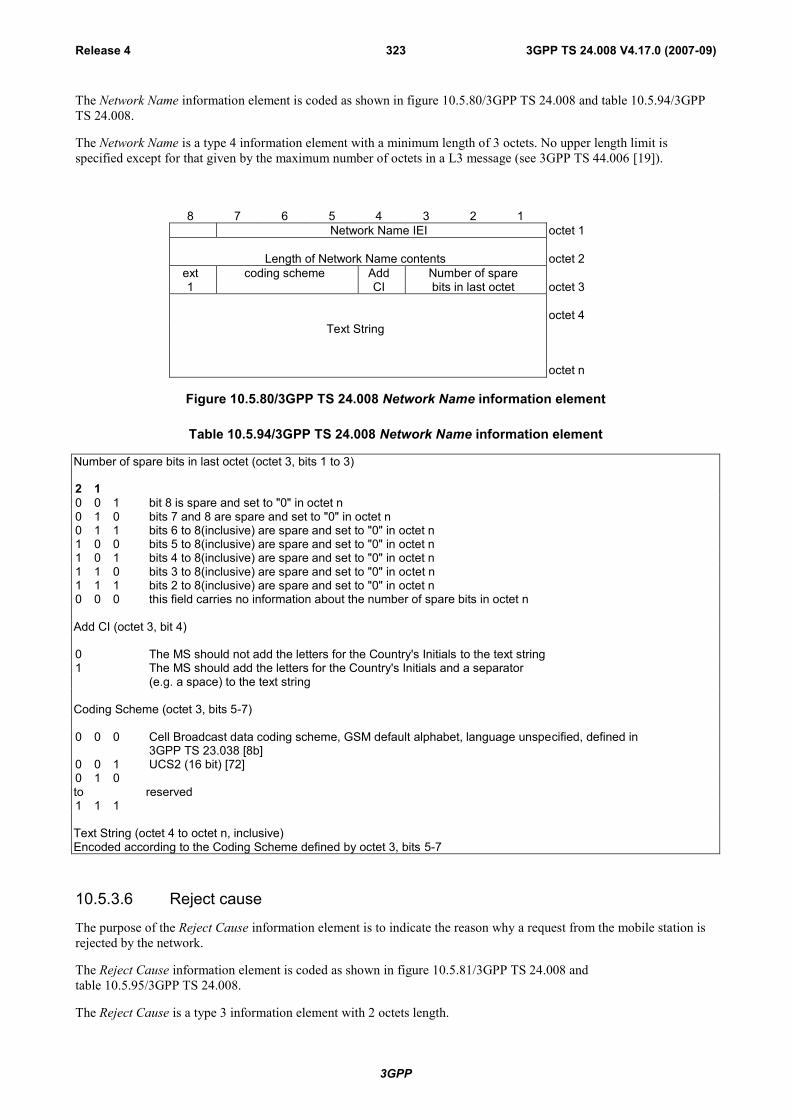
3GPP
3GPP TS 24.008 V4.17.0 (2007-09)Release 4 323
The Network Name information element is coded as shown in figure 10.5.80/3GPP TS 24.008 and table 10.5.94/3GPPTS 24.008.
The Network Name is a type 4 information element with a minimum length of 3 octets. No upper length limit isspecified except for that given by the maximum number of octets in a L3 message (see 3GPP TS 44.006 [19]).
8 7 6 5 4 3 2 1Network Name IEI octet 1
Length of Network Name contents octet 2ext1
coding scheme AddCI
Number of sparebits in last octet octet 3
octet 4Text String
octet n
Figure 10.5.80/3GPP TS 24.008 Network Name information element
Table 10.5.94/3GPP TS 24.008 Network Name information element
Number of spare bits in last octet (octet 3, bits 1 to 3)
2 10 0 1 bit 8 is spare and set to "0" in octet n0 1 0 bits 7 and 8 are spare and set to "0" in octet n0 1 1 bits 6 to 8(inclusive) are spare and set to "0" in octet n1 0 0 bits 5 to 8(inclusive) are spare and set to "0" in octet n1 0 1 bits 4 to 8(inclusive) are spare and set to "0" in octet n1 1 0 bits 3 to 8(inclusive) are spare and set to "0" in octet n1 1 1 bits 2 to 8(inclusive) are spare and set to "0" in octet n0 0 0 this field carries no information about the number of spare bits in octet n
Add CI (octet 3, bit 4)
0 The MS should not add the letters for the Country's Initials to the text string1 The MS should add the letters for the Country's Initials and a separator
(e.g. a space) to the text string
Coding Scheme (octet 3, bits 5-7)
0 0 0 Cell Broadcast data coding scheme, GSM default alphabet, language unspecified, defined in3GPP TS 23.038 [8b]
0 0 1 UCS2 (16 bit) [72]0 1 0to reserved1 1 1
Text String (octet 4 to octet n, inclusive)Encoded according to the Coding Scheme defined by octet 3, bits 5-7
10.5.3.6 Reject cause
The purpose of the Reject Cause information element is to indicate the reason why a request from the mobile station isrejected by the network.
The Reject Cause information element is coded as shown in figure 10.5.81/3GPP TS 24.008 andtable 10.5.95/3GPP TS 24.008.
The Reject Cause is a type 3 information element with 2 octets length.

3GPP
3GPP TS 24.008 V4.17.0 (2007-09)Release 4 324
8 7 6 5 4 3 2 1Reject cause IEI octet 1
reject cause value octet 2
Figure 10.5.81/3GPP TS 24.008 Reject Cause information element
Table 10.5.95/3GPP TS 24.008: Reject Cause information element
Reject cause value (octet 2)Bits8 7 6 5 4 3 2 10 0 0 0 0 0 1 0 IMSI unknown in HLR0 0 0 0 0 0 1 1 Illegal MS0 0 0 0 0 1 0 0 IMSI unknown in VLR0 0 0 0 0 1 0 1 IMEI not accepted0 0 0 0 0 1 1 0 Illegal ME0 0 0 0 1 0 1 1 PLMN not allowed0 0 0 0 1 1 0 0 Location Area not allowed0 0 0 0 1 1 0 1 Roaming not allowed in this location area0 0 0 0 1 1 1 1 No Suitable Cells In Location Area0 0 0 1 0 0 0 1 Network failure0 0 0 1 0 1 0 0 MAC failure0 0 0 1 0 1 0 1 Synch failure0 0 0 1 0 1 1 0 Congestion0 0 0 1 0 1 1 1 GSM authentication unacceptable0 0 1 0 0 0 0 0 Service option not supported0 0 1 0 0 0 0 1 Requested service option not subscribed0 0 1 0 0 0 1 0 Service option temporarily out of order0 0 1 0 0 1 1 0 Call cannot be identified0 0 1 1 0 0 0 0 }to } retry upon entry into a new cell0 0 1 1 1 1 1 1 }0 1 0 1 1 1 1 1 Semantically incorrect message0 1 1 0 0 0 0 0 Invalid mandatory information0 1 1 0 0 0 0 1 Message type non-existent or not implemented0 1 1 0 0 0 1 0 Message type not compatible with the protocol state0 1 1 0 0 0 1 1 Information element non-existent or not implemented0 1 1 0 0 1 0 0 Conditional IE error0 1 1 0 0 1 0 1 Message not compatible with the protocol state0 1 1 0 1 1 1 1 Protocol error, unspecified
Any other value received by the mobile station shall be treated as 0010 0010,'Service option temporarily out of order'. Any other value received by the networkshall be treated as 0110 1111, 'Protocol error, unspecified'.
NOTE: The listed reject cause values are defined in Annex G.
10.5.3.7 Follow-on Proceed
The purpose of the Follow-on Proceed information element is to indicate that an MM connection may be established onan existing RR connection.
The Follow-on Proceed information element is coded as shown in figure 10.5.82/3GPP TS 24.008.
The Follow-on Proceed is a type 2 information element.
8 7 6 5 4 3 2 1Follow-on Proceed IEI octet 1
Figure 10.5.82/3GPP TS 24.008 Follow-on Proceed information element

3GPP
3GPP TS 24.008 V4.17.0 (2007-09)Release 4 325
10.5.3.8 Time Zone
The purpose of this information element is to encode the offset between universal time and local timein steps of 15minutes.
The Time Zone information element is coded as shown in figure 10.5.83/3GPP TS 24.008 andtable 10.5.96/3GPP TS 24.008.
The Time Zone is a type 3 information element with a length of 2 octets.
8 7 6 5 4 3 2 1Time Zone IEI octet 1
Time Zoneoctet 2
Figure 10.5.83/3GPP TS 24.008 Time Zone information element
Table 10.5.96/3GPP TS 24.008 Time Zone information element
Time Zone (octet 2, bits 1-8)This field uses the same format as the Timezone field used in the TP-Service-Centre-Time-Stamp,which is defined in 3GPP TS 23.040 [90], and its value shall be set as defined in 3GPP TS 22.042[89]
10.5.3.9 Time Zone and Time
The purpose of the timezone part of this information element is to encode the offset between universal time and localtime in steps of 15 minutes.
The purpose of the time part of this information element is to encode the universal time at which this informationelement may have been sent by the network.
The Time Zone and Time information element is coded as shown in figure 10.5.84/3GPP TS 24.008 andtable 10.5.97/3GPP TS 24.008.
The Time Zone and Time is a type 3 information element with a length of 8 octets.
8 7 6 5 4 3 2 1Time Zone and Time IEI octet 1
Yearoctet 2
Monthoctet 3
Dayoctet 4
Houroctet 5
Minuteoctet 6
Secondoctet 7
Time zoneoctet 8
Figure 10.5.84/3GPP TS 24.008 Time Zone and Time information element

3GPP
3GPP TS 24.008 V4.17.0 (2007-09)Release 4 326
Table 10.5.97/3GPP TS 24.008 Timezone and Time information element
Year (octet 2, bits 1-8)
This field uses the same format as the Year field used in the TP-Service-Centre-Time-Stamp, which is defined in3GPP TS 23.040 [90], and its value shall be set as defined in 3GPP TS 22.042 [89]
Month (octet 3, bits 1-8)This field uses the same format as the Month field used in the TP-Service-Centre-Time-Stamp, which is defined in3GPP TS 23.040 [90], and its value shall be set as defined in 3GPP TS 22.042 [89].Day (octet 4, bits 1-8)This field uses the same format as the Day field used in the TP-Service-Centre-Time-Stamp, which is defined in 3GPPTS 23.040 [90], and its value shall be set as defined in 3GPP TS 22.042 [89].
Hour (octet 5, bits 1-8)This field uses the same format as the Hour field used in the TP-Service-Centre-Time-Stamp, which is defined in3GPP TS 23.040 [90], and its value shall be set as defined in 3GPP TS 22.042 [89].
Minute (octet 6, bits 1-8)This field uses the same format as the Minute field used in the TP-Service-Centre-Time-Stamp, which is defined in3GPP TS 23.040 [90], and its value shall be set as defined in 3GPP TS 22.042 [89].
Second (octet 7, bits 1-8)This field uses the same format as the Second field used in the TP-Service-Centre-Time-Stamp, which is defined in3GPP TS 23.040 [90], and its value shall be set as defined in 3GPP TS 22.042 [89].
Time Zone (octet 8, bits 1-8)This field uses the same format as the Time Zone field used in the TP-Service-Centre-Time-Stamp, which is defined in3GPP TS 23.040 [90], and its value shall be set as defined in 3GPP TS 22.042 [89].
NOTE: Due to ambiguities in earlier versions of the protocol specifications, some mobile stations may interpretthe received NITZ time as local time. This may result in incorrect time settings in the mobile.
10.5.3.10 CTS permission
The purpose of the CTS permission information element is to indicate that the mobile station is allowed to use GSM-Cordless Telephony System in the Location Area. The CTS permission information element is coded as shown infigure 10.5.84a/3GPP TS 24.008.
The CTS permission is a type 2 information element.
8 7 6 5 4 3 2 1CTS Permission IEI octet 1
Figure 10.5.84a/3GPP TS 24.008 CTS permission information element
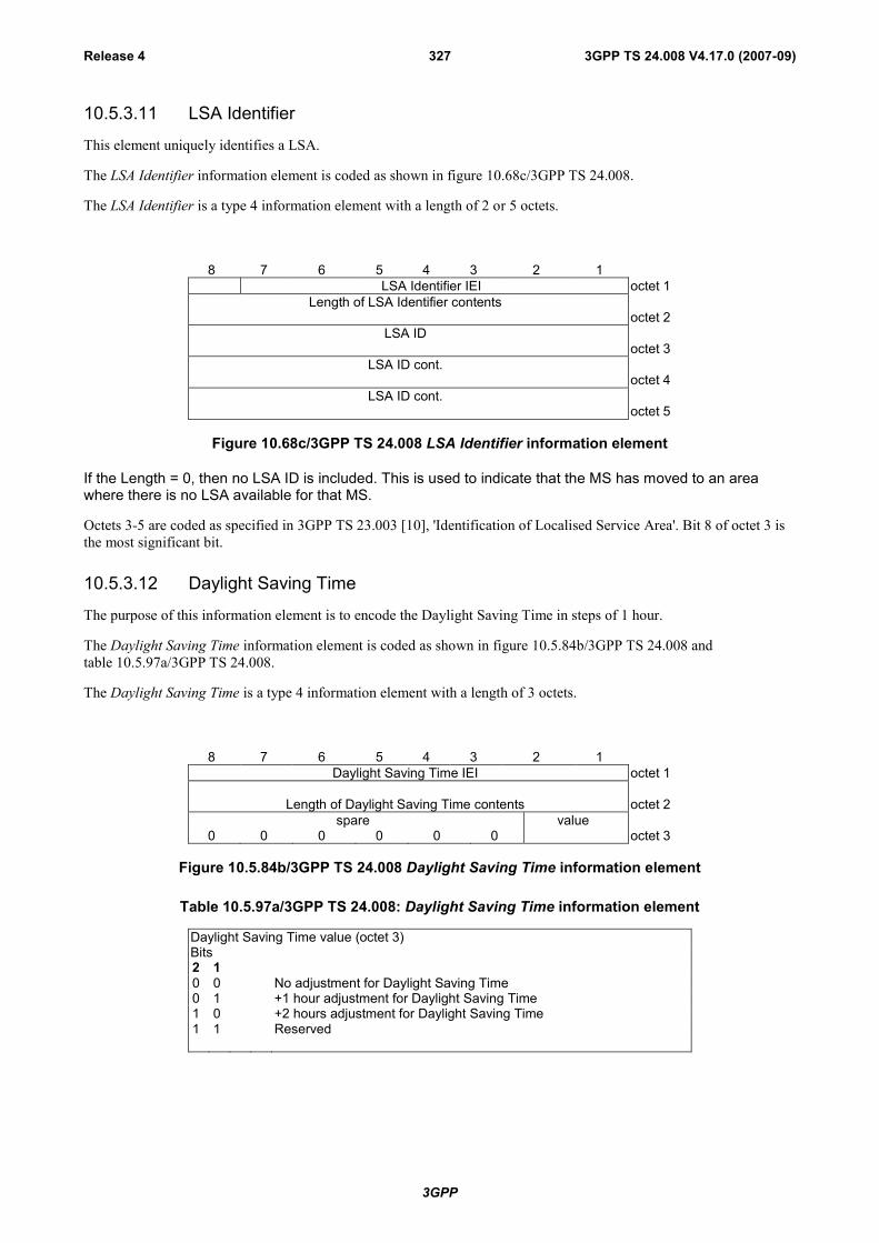
3GPP
3GPP TS 24.008 V4.17.0 (2007-09)Release 4 327
10.5.3.11 LSA Identifier
This element uniquely identifies a LSA.
The LSA Identifier information element is coded as shown in figure 10.68c/3GPP TS 24.008.
The LSA Identifier is a type 4 information element with a length of 2 or 5 octets.
8 7 6 5 4 3 2 1LSA Identifier IEI octet 1
Length of LSA Identifier contentsoctet 2
LSA IDoctet 3
LSA ID cont.octet 4
LSA ID cont.octet 5
Figure 10.68c/3GPP TS 24.008 LSA Identifier information element
If the Length = 0, then no LSA ID is included. This is used to indicate that the MS has moved to an areawhere there is no LSA available for that MS.
Octets 3-5 are coded as specified in 3GPP TS 23.003 [10], 'Identification of Localised Service Area'. Bit 8 of octet 3 isthe most significant bit.
10.5.3.12 Daylight Saving Time
The purpose of this information element is to encode the Daylight Saving Time in steps of 1 hour.
The Daylight Saving Time information element is coded as shown in figure 10.5.84b/3GPP TS 24.008 andtable 10.5.97a/3GPP TS 24.008.
The Daylight Saving Time is a type 4 information element with a length of 3 octets.
8 7 6 5 4 3 2 1Daylight Saving Time IEI octet 1
Length of Daylight Saving Time contents octet 2spare value
0 0 0 0 0 0 octet 3
Figure 10.5.84b/3GPP TS 24.008 Daylight Saving Time information element
Table 10.5.97a/3GPP TS 24.008: Daylight Saving Time information element
Daylight Saving Time value (octet 3)Bits2 10 0 No adjustment for Daylight Saving Time0 1 +1 hour adjustment for Daylight Saving Time1 0 +2 hours adjustment for Daylight Saving Time1 1 Reserved

3GPP
3GPP TS 24.008 V4.17.0 (2007-09)Release 4 328
10.5.4 Call control information elements
10.5.4.1 Extensions of codesets
There is a certain number of possible information element identifier values using the formatting rules described insubclause 10.5: 128 from the type 3 & 4 information element format and at least 8 from the type 1 & 2 informationelement format.
One value in the type 1 format is specified for shift operations described below. One other value in both the type 3 & 4and type 1 format is reserved. This leaves 133 information element identifier values available for assignment.
It is possible to expand this structure to eight codesets of 133 information element identifier values each. One commonvalue in the type 1 format is employed in each codeset to facilitate shifting from one codeset to another. The contents ofthis shift information element identifies the codeset to be used for the next information element or elements. Thecodeset in use at any given time is referred to as the "active codeset". By convention, codeset 0 is the initially activecodeset.
Two codeset shifting procedures are supported: locking shift and non-locking shift.
Codeset 5 is reserved for information elements reserved for national use.
Codeset 6 is reserved for information elements specific to the local network (either public or private).
Codeset 7 is reserved for user-specific information elements.
The coding rules specified in subclause 10.5 shall apply for information elements belonging to any active codeset.
Transitions from one active codeset to another (i.e. by means of the locking shift procedure) may only be made to acodeset with a higher numerical value than the codeset being left.
An information element belonging to codeset 5, 6 or 7 may appear together with information elements belonging tocodeset 0, by using the non-locking shift procedure (see subclause 10.5.4.3).
A user or network equipment shall have the capability to recognize a shift information element and to determine thelength of the following information element, although the equipment need not be able to interpret and act on the contentof the information element. This enables the equipment to determine the start of the subsequent information element.
10.5.4.2 Locking shift procedure
The locking shift procedure employs an information element to indicate the new active codeset. The specified codesetremains active until another locking shift information element is encountered which specifies the use of another codeset.For example, codeset 0 is active at the start of message content analysis. If a locking shift to codeset 5 is encountered,the next information elements will be interpreted according to the information element identifiers assigned in codeset 5,until another shift information element is encountered. This procedure is used only to shift to a higher order codesetthan the one being left.
The locking shift is valid only within that message which contains the locking shift information element. At the start ofevery message content analysis, the active codeset is codeset 0.
The locking shift information element uses the type 1 information element format and coding shown infigure 10.5.85/3GPP TS 24.008 and table 10.5.98/3GPP TS 24.008.
8 7 6 5 4 3 2 1
Shift identifier0 New codeset
identificationoctet 1
"0" in this position indicates locking shift
Figure 10.5.85/3GPP TS 24.008 Locking shift element

3GPP
3GPP TS 24.008 V4.17.0 (2007-09)Release 4 329
Table 10.5.98/3GPP TS 24.008: Locking shift element
Codeset identification (octet 1):Bits3 2 10 0 0 not applicable0 0 1 }to } reserved1 0 0 }1 0 1 codeset 5: information elements for national use1 1 0 codeset 6: information elements specific to the local network
(either public or private)1 1 1 codeset 7: user-specific information elements
10.5.4.3 Non-locking shift procedure
The non-locking shift procedure provides a temporary shift to the specified lower or higher codeset. The non-lockingshift procedure uses a type 1 information element to indicate the codeset to be used to interpret the next informationelement. After the interpretation of the next information element, the active codeset is again used for interpreting anyfollowing information elements. For example, codeset 0 is active at the beginning of message content analysis. If a non-locking shift to codeset 6 is encountered, only the next information element is interpreted according to the informationelement identifiers assigned in codeset 6. After this information element is interpreted, codeset 0 will again be used tointerpret the following information elements. A non-locking shift information element indicating the current codesetshall not be regarded as an error.
A locking shift information element shall not follow directly a non-locking shift information element. If thiscombination is received, it shall be interpreted as though a locking shift information element had been received.
The non-locking shift information element uses the type 1 information format and coding shown in figure 10.5.86/3GPPTS 24.008 and table 10.5.99/3GPP TS 24.008.
8 7 6 5 4 3 2 1
Shift identifier1 Temporary codeset
identificationoctet 1
"1" in this position indicates non-locking shift
Figure 10.5.86/3GPP TS 24.008 Non-locking shift element
Table 10.5.99/3GPP TS 24.008: Non-locking shift element
Codeset identification (octet 1):Bits3 2 10 0 0 codeset 0 (initially active):
3GPP TS 24.008 information elements0 0 1 }to } reserved1 0 0 }1 0 1 codeset 5: information elements for national use1 1 0 codeset 6: information elements specific to the local network
(either public or private)1 1 1 codeset 7: user-specific information elements
10.5.4.4 Auxiliary states
The purpose of the auxiliary states information element is to describe the current status of the auxiliary states of a call inthe call control states "active" and "mobile originating modify". (See TSs 3GPP TS 24.083 and 24.084 [28])
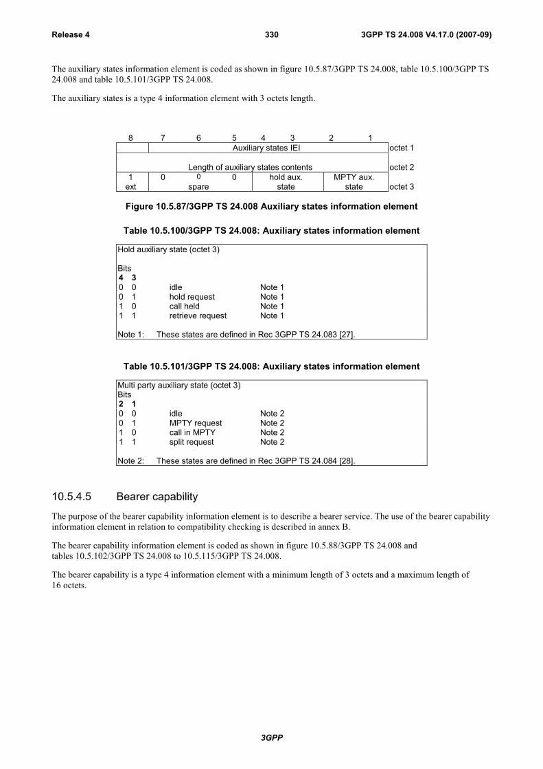
3GPP
3GPP TS 24.008 V4.17.0 (2007-09)Release 4 330
The auxiliary states information element is coded as shown in figure 10.5.87/3GPP TS 24.008, table 10.5.100/3GPP TS24.008 and table 10.5.101/3GPP TS 24.008.
The auxiliary states is a type 4 information element with 3 octets length.
8 7 6 5 4 3 2 1Auxiliary states IEI octet 1
Length of auxiliary states contents octet 21 0 0 0 hold aux. MPTY aux.
ext spare state state octet 3
Figure 10.5.87/3GPP TS 24.008 Auxiliary states information element
Table 10.5.100/3GPP TS 24.008: Auxiliary states information element
Hold auxiliary state (octet 3)
Bits4 30 0 idle Note 10 1 hold request Note 11 0 call held Note 11 1 retrieve request Note 1
Note 1: These states are defined in Rec 3GPP TS 24.083 [27].
Table 10.5.101/3GPP TS 24.008: Auxiliary states information element
Multi party auxiliary state (octet 3)Bits2 10 0 idle Note 20 1 MPTY request Note 21 0 call in MPTY Note 21 1 split request Note 2
Note 2: These states are defined in Rec 3GPP TS 24.084 [28].
10.5.4.5 Bearer capability
The purpose of the bearer capability information element is to describe a bearer service. The use of the bearer capabilityinformation element in relation to compatibility checking is described in annex B.
The bearer capability information element is coded as shown in figure 10.5.88/3GPP TS 24.008 andtables 10.5.102/3GPP TS 24.008 to 10.5.115/3GPP TS 24.008.
The bearer capability is a type 4 information element with a minimum length of 3 octets and a maximum length of16 octets.

3GPP
3GPP TS 24.008 V4.17.0 (2007-09)Release 4 331
8 7 6 5 4 3 2 1Bearer capability IEI octet 1
Length of the bearer capability contents octet 20/1ext
radiochannel
requirement
co-dingstd
transfer
mode
informationtransfer
capabilityoctet 3
0/1 0 0ext co-
dingCTM spare speech version
indicationoctet 3a*
0/1 0 0 0ext co-
dingspare spare speech version
indicationoctet 3b etc*
1ext
comp-ress. structure
dupl.mode
configur.
NIRR esta-bli. octet 4*
0/1 0 0 rate signallingext access id. adaption access protocol octet 5*0/1 Other rate 0 0 0ext Other ITC adaption Spare octet 5a*1
extHdr/
noHdrMultiframe
Mode LLI Assignor/e
Inb.neg
0Spare octet 5b*
0/1 0 1 User information sync/ext layer 1 id. layer 1 protocol async octet 6*0/1ext
numb.stopbits
nego-tia-tion
numb.databits
user rate octet 6a*
0/1ext
intermed.rate
NICon TX
NICon RX Parity octet 6b*
0/1ext
connectionelement modem type octet 6c*
0/1ext
Othermodem type Fixed network user rate octet 6d*
0/1ext
Acceptablechannelcodings
Maximum number oftraffic channels octet 6e*
0/1ext
UIMI Wanted air interfaceuser rate octet 6f*
1ext
Acceptablechannel codings Asymmetry
0 0
extended Indication Spare octet 6g*1 1 0 User information
ext layer 2 id. layer 2 protocol octet 7*
Figure 10.5.88/3GPP TS 24.008 Bearer capability information element
NOTE 1: The coding of the octets of the bearer capability information element is not conforming to ITU Q.931.
An MS shall encode the Bearer Capability infomation element according to GSM call control requirements also if it isrequesting for a UMTS service, with the following exceptions:
1. A mobile station not supporting GSM shall set the following parameters to the value "0":- Maximum number of traffic channels (octet 6e, bits 1-3)- Acceptable Channel coding(s) (octet 6e, bits 4, 5 and 7).
2. Furthermore, a mobile station not supporting GSM shall also set the following parameters to the value "0",if the respective octets have to be included in the bearer capability information element according tosubclause 10.5.4.5.1 and 3GPP TS 27.001 [36]:- UIMI, User initiated modification indication (octet 6f, bits 5-7)- Acceptable Channel Codings extended (octet 6g, bits 5-7).
For UTRAN access the following parameters are irrelevant for specifying the radio access bearer, because multipletraffic channels (multislot) are not deployed [3GPP TS 23.034]. However, the parameters if received, shall be stored inthe MSC, and forwarded at handover:- Maximum number of traffic channels (octet 6e, bits 1-3)
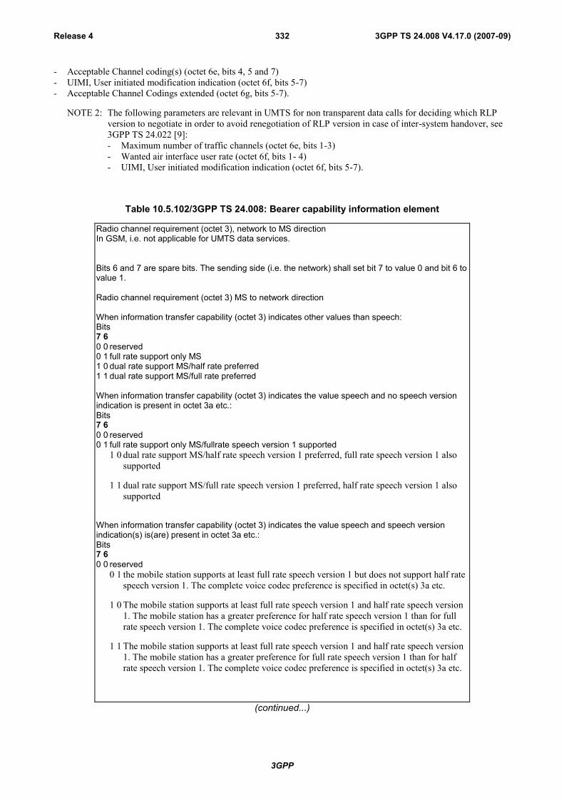
3GPP
3GPP TS 24.008 V4.17.0 (2007-09)Release 4 332
- Acceptable Channel coding(s) (octet 6e, bits 4, 5 and 7)- UIMI, User initiated modification indication (octet 6f, bits 5-7)- Acceptable Channel Codings extended (octet 6g, bits 5-7).
NOTE 2: The following parameters are relevant in UMTS for non transparent data calls for deciding which RLPversion to negotiate in order to avoid renegotiation of RLP version in case of inter-system handover, see3GPP TS 24.022 [9]:- Maximum number of traffic channels (octet 6e, bits 1-3)- Wanted air interface user rate (octet 6f, bits 1- 4)- UIMI, User initiated modification indication (octet 6f, bits 5-7).
Table 10.5.102/3GPP TS 24.008: Bearer capability information element
Radio channel requirement (octet 3), network to MS directionIn GSM, i.e. not applicable for UMTS data services.
Bits 6 and 7 are spare bits. The sending side (i.e. the network) shall set bit 7 to value 0 and bit 6 tovalue 1.
Radio channel requirement (octet 3) MS to network direction
When information transfer capability (octet 3) indicates other values than speech:Bits7 60 0 reserved0 1 full rate support only MS1 0 dual rate support MS/half rate preferred1 1 dual rate support MS/full rate preferred
When information transfer capability (octet 3) indicates the value speech and no speech versionindication is present in octet 3a etc.:Bits7 60 0 reserved0 1 full rate support only MS/fullrate speech version 1 supported
1 0 dual rate support MS/half rate speech version 1 preferred, full rate speech version 1 alsosupported
1 1 dual rate support MS/full rate speech version 1 preferred, half rate speech version 1 alsosupported
When information transfer capability (octet 3) indicates the value speech and speech versionindication(s) is(are) present in octet 3a etc.:Bits7 60 0 reserved
0 1 the mobile station supports at least full rate speech version 1 but does not support half ratespeech version 1. The complete voice codec preference is specified in octet(s) 3a etc.
1 0 The mobile station supports at least full rate speech version 1 and half rate speech version1. The mobile station has a greater preference for half rate speech version 1 than for fullrate speech version 1. The complete voice codec preference is specified in octet(s) 3a etc.
1 1 The mobile station supports at least full rate speech version 1 and half rate speech version1. The mobile station has a greater preference for full rate speech version 1 than for halfrate speech version 1. The complete voice codec preference is specified in octet(s) 3a etc.
(continued...)
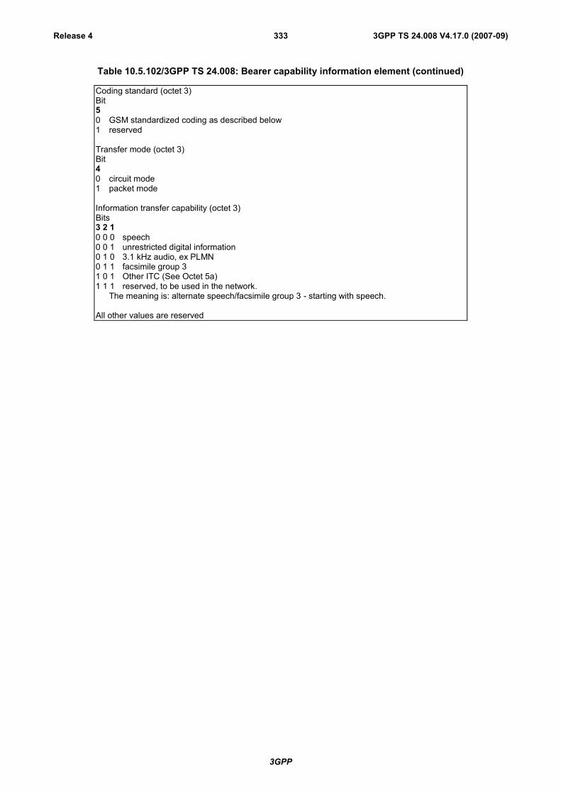
3GPP
3GPP TS 24.008 V4.17.0 (2007-09)Release 4 333
Table 10.5.102/3GPP TS 24.008: Bearer capability information element (continued)
Coding standard (octet 3)Bit50 GSM standardized coding as described below1 reserved
Transfer mode (octet 3)Bit40 circuit mode1 packet mode
Information transfer capability (octet 3)Bits3 2 10 0 0 speech0 0 1 unrestricted digital information0 1 0 3.1 kHz audio, ex PLMN0 1 1 facsimile group 31 0 1 Other ITC (See Octet 5a)1 1 1 reserved, to be used in the network.
The meaning is: alternate speech/facsimile group 3 - starting with speech.
All other values are reserved

3GPP
3GPP TS 24.008 V4.17.0 (2007-09)Release 4 334
Table 10.5.103/3GPP TS 24.008 Bearer capability information element
Octet(s) 3a etc. MS to network directionOctet(s) 3a etc., bits 1 to 4 shall only be used to convey speech coding information belonging to aGSM Radio Access. When included for a UMTS call establishment they shall be used forhandover to a GSM Radio Acess.A mobile station supporting CTM text telephony, but not supporting GSM radio access shallencode octet 3a, bits 1 to 4 as “no speech version supported for GSM radio access”.
Coding
Bit70 octet used for extension of information transfer capability1 octet used for other extension of octet 3
When information transfer capability (octet 3) indicates speech and coding (bit 7 in octet 3a etc.) iscoded as 0, bits 1 through 6 are coded:
CTM text telephony indication (octet 3a)Bit60 CTM text telephony is not supported1 CTM text telephony is supported
In this version of the protocol, bit 6 in octet 3a shall be ignored by the network.
Bit 6 in octet(s) 3b etc. is spare.
Bit 5 in octet(s) 3a etc. is spare.
Speech version indication (octet(s) 3a etc.)Bits4 3 2 10 0 0 0GSM full rate speech version 10 0 1 0GSM full rate speech version 20 1 0 0GSM full rate speech version 30 0 0 1GSM half rate speech version 10 1 0 1GSM half rate speech version 31 1 1 1no speech version supported for GSM radio access (note 1)
All other values have the meaning "speech version tbd" and shall be ignoredwhen received.
NOTE 1: This value shall only be used by an MS supporting CTM text telephony, but notsupporting GSM radio access.
If octet 3 is extended with speech version indication(s) (octets 3a etc.), all speech versionssupported shall be indicated and be included in order of preference (the first octet (3a) has thehighest preference and so on).
If information transfer capability (octet 3) indicates speech and coding (bit 7 in octet 3a etc.) iscoded as 1, or the information transfer capability does not indicate speech, then the extensionoctet shall be ignored.
Octet(s) 3a etc. network to MS direction
The octet(s) 3a etc. shall be ignored by the MS.

3GPP
3GPP TS 24.008 V4.17.0 (2007-09)Release 4 335
Table 10.5.104/3GPP TS 24.008: Bearer capability information element
Compression (octet 4), network to MS direction:Bit70 data compression not possible1 data compression possible
Compression (octet 4), MS to network direction:Bit70 data compression not allowed1 data compression allowed
Structure (octet 4)
Bits6 50 0 service data unit integrity1 1 unstructured
All other values are reserved.
Duplex mode (octet 4)Bit40 half duplex1 full duplex
Configuration (octet 4)Bit30 point-to-point
All other values are reserved.
NIRR (octet 4)(Negotiation of Intermediate Rate Requested)In GSM, i.e. not applicable for UMTS data services.
Bit20 No meaning is associated with this value.1 Data up to and including 4.8 kb/s, full rate, non-transparent, 6 kb/s radio interface rate isrequested.
Establishment (octet 4)Bit10 demand
All other values are reserved

3GPP
3GPP TS 24.008 V4.17.0 (2007-09)Release 4 336
Table 10.5.105/3GPP TS 24.008: Bearer capability information element
Access identity (octet 5)Bits7 60 0 octet identifier
All other values are reserved
Rate adaption (octet 5)Bits5 40 0 no rate adaption0 1 V.110, I.460/X.30 rate adaptation1 0 ITU-T X.31 flag stuffing1 1 Other rate adaption (see octet 5a)
Signalling access protocol (octet 5)
Bits3 2 10 0 1 I.440/4500 1 0 reserved: was allocated in earlier phases of the protocol0 1 1 reserved: was allocated in earlier phases of the protocol1 0 0 reserved: was allocated in earlier phases of the protocol.1 0 1 reserved: was allocated in earlier phases of the protocol1 1 0 reserved: was allocated in earlier phases of the protocol
All other values are reserved.
Table 10.5.106/3GPP TS 24.008: Bearer capability information element
Other ITC (octet 5a)If the value "Other ITC" is not signalled in the field "ITC" then the contents of this field shall beignored.
Bit7 60 0 restricted digital information
All other values are reserved
Other rate adaption (octet 5a)If the value " Other rate adaption" is not signalled in the field "Rate adaption" then the contents ofthis field shall be ignored.In UMTS, PIAFS shall be considered. In GSM, call shall be rejected if PIAFS requested.
Bit5 40 0 V.1200 1 H.223 & H.2451 0 PIAFS
All other values are reserved.

3GPP
3GPP TS 24.008 V4.17.0 (2007-09)Release 4 337
Table 10.5.107/3GPP TS 24.008: Bearer capability information element
Rate adaption header/no header (octet 5b)
Bit70 Rate adaption header not included1 Rate adaption header included
Multiple frame establishment support in data link (octet 5b)
Bit60 Multiple frame establishment not supported, only UI frames allowed1 Multiple frame establishment supported
Mode of operation (octet 5b)
Bit50 Bit transparent mode of operation1 Protocol sensitive mode of operation
Logical link identifier negotiation (octet 5b)
Bit40 Default, LLI=256 only1 Full protocol negotiation, (note: A connection over which protocol negotiation will
be executed is indicated in bit 2 of octet 5b)
Assignor/Assignee (octet 5b)
Bit30 Message originator is "default assignee"1 Message originator is "assignor only"
In band/Out of band negotiation (octet 5b)
Bit20 Negotiation is done in-band using logical link zero1 Negotiation is done with USER INFORMATION messages on a temporary
signalling connection
Bit 1 is spare and set to the value "0"
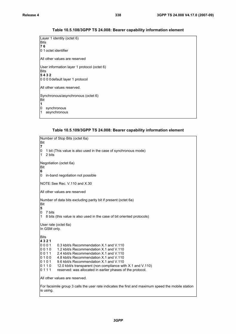
3GPP
3GPP TS 24.008 V4.17.0 (2007-09)Release 4 338
Table 10.5.108/3GPP TS 24.008: Bearer capability information element
Layer 1 identity (octet 6)Bits7 60 1 octet identifier
All other values are reserved
User information layer 1 protocol (octet 6)Bits5 4 3 20 0 0 0default layer 1 protocol
All other values reserved.
Synchronous/asynchronous (octet 6)Bit10 synchronous1 asynchronous
Table 10.5.109/3GPP TS 24.008: Bearer capability information element
Number of Stop Bits (octet 6a)Bit70 1 bit (This value is also used in the case of synchronous mode)1 2 bits
Negotiation (octet 6a)Bit60 in-band negotiation not possible
NOTE:See Rec. V.110 and X.30
All other values are reserved
Number of data bits excluding parity bit if present (octet 6a)Bit50 7 bits1 8 bits (this value is also used in the case of bit oriented protocols)
User rate (octet 6a)In GSM only.
Bits4 3 2 10 0 0 1 0.3 kbit/s Recommendation X.1 and V.1100 0 1 0 1.2 kbit/s Recommendation X.1 and V.1100 0 1 1 2.4 kbit/s Recommendation X.1 and V.1100 1 0 0 4.8 kbit/s Recommendation X.1 and V.1100 1 0 1 9.6 kbit/s Recommendation X.1 and V.1100 1 1 0 12.0 kbit/s transparent (non compliance with X.1 and V.110)0 1 1 1 reserved: was allocated in earlier phases of the protocol.
All other values are reserved.
For facsimile group 3 calls the user rate indicates the first and maximum speed the mobile stationis using.
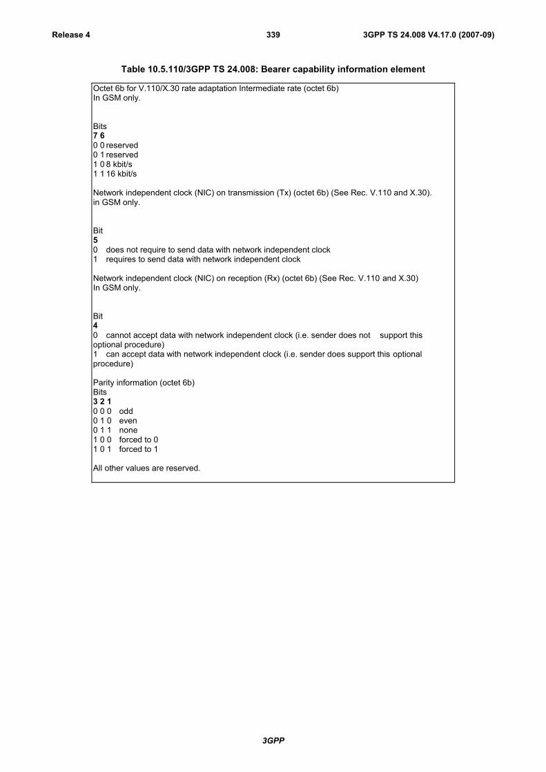
3GPP
3GPP TS 24.008 V4.17.0 (2007-09)Release 4 339
Table 10.5.110/3GPP TS 24.008: Bearer capability information element
Octet 6b for V.110/X.30 rate adaptation Intermediate rate (octet 6b)In GSM only.
Bits7 60 0 reserved0 1 reserved1 0 8 kbit/s1 1 16 kbit/s
Network independent clock (NIC) on transmission (Tx) (octet 6b) (See Rec. V.110 and X.30).in GSM only.
Bit50 does not require to send data with network independent clock1 requires to send data with network independent clock
Network independent clock (NIC) on reception (Rx) (octet 6b) (See Rec. V.110 and X.30)In GSM only.
Bit40 cannot accept data with network independent clock (i.e. sender does not support thisoptional procedure)1 can accept data with network independent clock (i.e. sender does support this optionalprocedure)
Parity information (octet 6b)Bits3 2 10 0 0 odd0 1 0 even0 1 1 none1 0 0 forced to 01 0 1 forced to 1
All other values are reserved.

3GPP
3GPP TS 24.008 V4.17.0 (2007-09)Release 4 340
Table 10.5.111/3GPP TS 24.008: Bearer capability information element
Connection element (octet 6c)Bit7 60 0 transparent0 1 non transparent (RLP)1 0 both, transparent preferred1 1 both, non transparent preferred
The requesting end (e.g. the one sending the SETUP message) should use the 4 valuesdepending on its capabilities to support the different modes. The answering party shall only usethe codings 00 or 01, based on its own capabilities and the proposed choice if any. If both MS andnetwork support both transparent and non transparent, priority should be given to the MSpreference.
Modem type (octet 6c)Bits5 4 3 2 10 0 0 0 0 none0 0 0 0 1 V.21 (note 1)0 0 0 1 0 V.22 (note 1)0 0 0 1 1 V.22 bis (note 1)0 0 1 0 0 reserved: was allocated in earlier phases of the protocol0 0 1 0 1 V.26 ter (note 1)0 0 1 1 0 V.320 0 1 1 1 modem for undefined interface0 1 0 0 0 autobauding type 1
All other values are reserved. Note 1: In GSM only.

3GPP
3GPP TS 24.008 V4.17.0 (2007-09)Release 4 341
Table 10.5.112/3GPP TS 24.008: Bearer capability information element
Other modem type (octet 6d)Bits7 60 0 no other modem type specified in this field1 0 V.34
All other values are reserved.
Fixed network user rate (octet 6d)Bit5 4 3 2 10 0 0 0 0 Fixed network user rate not applicable/No meaning is associated
with this value.0 0 0 0 1 9.6 kbit/s Recommendation X.1 and V.1100 0 0 1 0 14.4 kbit/s Recommendation X.1 and V.1100 0 0 1 1 19.2 kbit/s Recommendation X.1 and V.1100 0 1 0 0 28.8 kbit/s Recommendation X.1 and V.1100 0 1 0 1 38.4 kbit/s Recommendation X.1 and V.1100 0 1 1 0 48.0 kbit/s Recommendation X.1 and V.110(synch) (note 1)0 0 1 1 1 56.0 kbit/s Recommendation X.1 and V.110(synch) /bit transparent0 1 0 0 0 64.0 kbit/s bit transparent0 1 0 0 1 33.6 kbit/s bit transparent (note 2)0 1 0 1 0 32.0 kbit/s Recommendation I.4600 1 0 1 1 31.2 kbit/s Recommendation V.34 (note 2)
The value 31.2 kbit/s Recommendation V.34 shall be used only by the network to inform the MSabout FNUR modification due to negotiation between the modems in a 3.1 kHz multimedia call.
All other values are reserved.Note 1: In GSM only.Note 2: In UMTS only
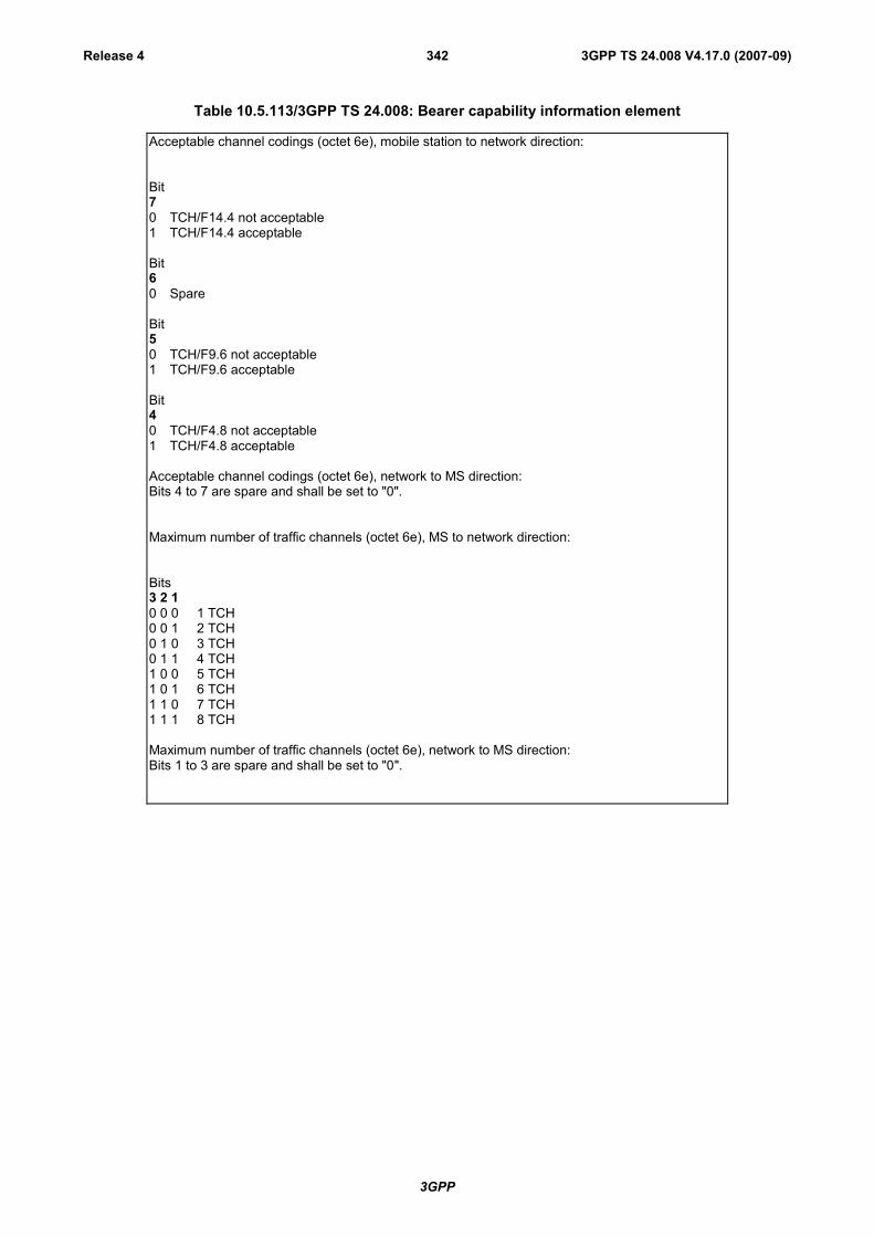
3GPP
3GPP TS 24.008 V4.17.0 (2007-09)Release 4 342
Table 10.5.113/3GPP TS 24.008: Bearer capability information element
Acceptable channel codings (octet 6e), mobile station to network direction:
Bit70 TCH/F14.4 not acceptable1 TCH/F14.4 acceptable
Bit60 Spare
Bit50 TCH/F9.6 not acceptable1 TCH/F9.6 acceptable
Bit40 TCH/F4.8 not acceptable1 TCH/F4.8 acceptable
Acceptable channel codings (octet 6e), network to MS direction:Bits 4 to 7 are spare and shall be set to "0".
Maximum number of traffic channels (octet 6e), MS to network direction:
Bits3 2 10 0 0 1 TCH0 0 1 2 TCH0 1 0 3 TCH0 1 1 4 TCH1 0 0 5 TCH1 0 1 6 TCH1 1 0 7 TCH1 1 1 8 TCH
Maximum number of traffic channels (octet 6e), network to MS direction:Bits 1 to 3 are spare and shall be set to "0".

3GPP
3GPP TS 24.008 V4.17.0 (2007-09)Release 4 343
Table 10.5.114/3GPP TS 24.008: Bearer capability information element
UIMI, User initiated modification indication (octet 6f),
7 6 50 0 0 User initiated modification not allowed/required/applicable0 0 1 User initiated modification up to 1 TCH/F allowed/may be requested0 1 0 User initiated modification up to 2 TCH/F allowed/may be requested0 1 1 User initiated modification up to 3 TCH/F allowed/may be requested1 0 0 User initiated modification up to 4 TCH/F allowed/may be requested
All other values shall be interpreted as "User initiated modification up to 4 TCH/F may be requested".
User initiated modification indication is not applicable for transparent connection.
Wanted air interface user rate (octet 6f), MS to network direction:Bits4 3 2 10 0 0 0Air interface user rate not applicable/No meaning associated with this value0 0 0 1 9.6 kbit/s0 0 1 0 14.4 kbit/s0 0 1 1 19.2 kbit/s0 1 0 1 28.8 kbit/s0 1 1 0 38.4 kbit/s0 1 1 1 43.2 kbit/s1 0 0 0 57.6 kbit/s1 0 0 1 interpreted by the network as 38.4 kbit/s in this version of the protocol1 0 1 0 interpreted by the network as 38.4 kbit/s in this version of the protocol1 0 1 1 interpreted by the network as 38.4 kbit/s in this version of the protocol1 1 0 0 interpreted by the network as 38.4 kbit/s in this version of the protocol
All other values are reserved.
Wanted air interface user rate (octet 6f), network to MS direction:Bits 1 to 4 are spare and shall be set to "0".

3GPP
3GPP TS 24.008 V4.17.0 (2007-09)Release 4 344
Table 10.5.115/3GPP TS 24.008: Bearer capability information element
Layer 2 identity (octet 7)Bits7 61 0 octet identifier
All other values are reserved
User information layer 2 protocol (octet 7)
Bits5 4 3 2 10 0 1 1 0 reserved: was allocated in earlier phases of the protocol0 1 0 0 0 ISO 6429, codeset 0 (DC1/DC3)0 1 0 0 1 reserved: was allocated but never used in earlier phases of the protocol0 1 0 1 0 videotex profile 10 1 1 0 0 COPnoFlCt (Character oriented Protocol with no Flow Control
mechanism)0 1 1 0 1 reserved: was allocated in earlier phases of the protocol
All other values are reserved.
Table 10.5.115a/3GPP TS 24.008: Bearer capability information element
Acceptable Channel Codings extended (octet 6g) mobile station to network direction:
Bit70 TCH/F28.8 not acceptable1 TCH/F28.8 acceptable
Bit60 TCH/F32.0 not acceptable1 TCH/F32.0 acceptable
Bit50 TCH/F43.2 not acceptable1 TCH/F43.2 acceptableChannel Coding Asymmetry Indication
Bits4 30 0 Channel coding symmetry preferred1 0 Downlink biased channel coding asymmetry is preferred0 1 Uplink biased channel coding asymmetry is preferred1 1 Unused, if received it shall be interpreted as "Channel coding symmetry preferred"
EDGE Channel Codings (octet 6g), network to MS direction:
Bits 3 to 7 are spare and shall be set to "0".
Bits 2 and 1 are spare.
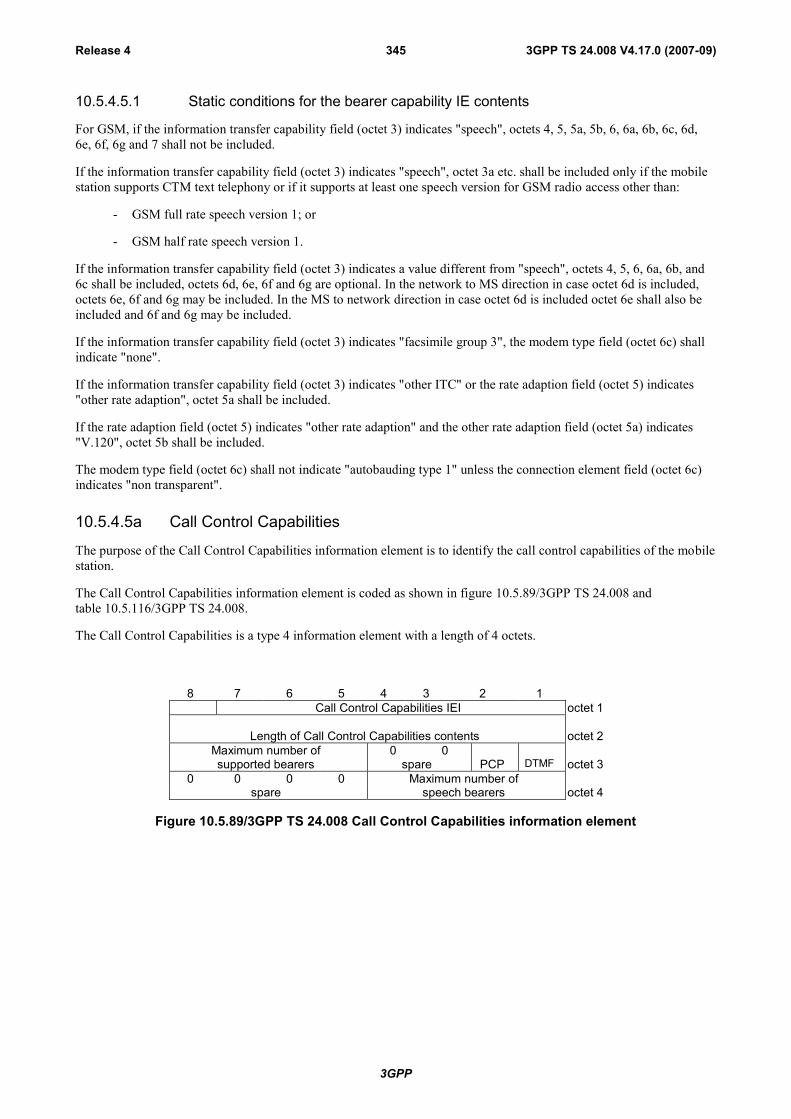
3GPP
3GPP TS 24.008 V4.17.0 (2007-09)Release 4 345
10.5.4.5.1 Static conditions for the bearer capability IE contents
For GSM, if the information transfer capability field (octet 3) indicates "speech", octets 4, 5, 5a, 5b, 6, 6a, 6b, 6c, 6d,6e, 6f, 6g and 7 shall not be included.
If the information transfer capability field (octet 3) indicates "speech", octet 3a etc. shall be included only if the mobilestation supports CTM text telephony or if it supports at least one speech version for GSM radio access other than:
- GSM full rate speech version 1; or
- GSM half rate speech version 1.
If the information transfer capability field (octet 3) indicates a value different from "speech", octets 4, 5, 6, 6a, 6b, and6c shall be included, octets 6d, 6e, 6f and 6g are optional. In the network to MS direction in case octet 6d is included,octets 6e, 6f and 6g may be included. In the MS to network direction in case octet 6d is included octet 6e shall also beincluded and 6f and 6g may be included.
If the information transfer capability field (octet 3) indicates "facsimile group 3", the modem type field (octet 6c) shallindicate "none".
If the information transfer capability field (octet 3) indicates "other ITC" or the rate adaption field (octet 5) indicates"other rate adaption", octet 5a shall be included.
If the rate adaption field (octet 5) indicates "other rate adaption" and the other rate adaption field (octet 5a) indicates"V.120", octet 5b shall be included.
The modem type field (octet 6c) shall not indicate "autobauding type 1" unless the connection element field (octet 6c)indicates "non transparent".
10.5.4.5a Call Control Capabilities
The purpose of the Call Control Capabilities information element is to identify the call control capabilities of the mobilestation.
The Call Control Capabilities information element is coded as shown in figure 10.5.89/3GPP TS 24.008 andtable 10.5.116/3GPP TS 24.008.
The Call Control Capabilities is a type 4 information element with a length of 4 octets.
8 7 6 5 4 3 2 1Call Control Capabilities IEI octet 1
Length of Call Control Capabilities contents octet 2Maximum number of 0 0supported bearers spare PCP DTMF octet 3
0 0 0 0 Maximum number ofspare speech bearers octet 4
Figure 10.5.89/3GPP TS 24.008 Call Control Capabilities information element
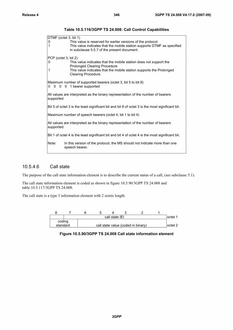
3GPP
3GPP TS 24.008 V4.17.0 (2007-09)Release 4 346
Table 10.5.116/3GPP TS 24.008: Call Control Capabilities
DTMF (octet 3, bit 1)0 This value is reserved for earlier versions of the protocol.1 This value indicates that the mobile station supports DTMF as specified
in subclause 5.5.7 of the present document.
PCP (octet 3, bit 2)0 This value indicates that the mobile station does not support the
Prolonged Clearing Procedure1 This value indicates that the mobile station supports the Prolonged
Clearing Procedure.
Maximum number of supported bearers (octet 3, bit 5 to bit 8)0 0 0 0 1 bearer supported
All values are interpreted as the binary representation of the number of bearerssupported.
Bit 5 of octet 3 is the least significant bit and bit 8 of octet 3 is the most significant bit.
Maximum number of speech bearers (octet 4, bit 1 to bit 4)
All values are interpreted as the binary representation of the number of bearerssupported.
Bit 1 of octet 4 is the least significant bit and bit 4 of octet 4 is the most significant bit.
Note: In this version of the protocol, the MS should not indicate more than onespeech bearer.
10.5.4.6 Call state
The purpose of the call state information element is to describe the current status of a call, (see subclause 5.1).
The call state information element is coded as shown in figure 10.5.90/3GPP TS 24.008 andtable 10.5.117/3GPP TS 24.008.
The call state is a type 3 information element with 2 octets length.
8 7 6 5 4 3 2 1call state IEI octet 1
codingstandard call state value (coded in binary) octet 2
Figure 10.5.90/3GPP TS 24.008 Call state information element

3GPP
3GPP TS 24.008 V4.17.0 (2007-09)Release 4 347
Table 10.5.117/3GPP TS 24.008: Call state information element
Coding standard (octet 2)Bits8 70 0 standardized coding as described in ITU-T Rec. Q.9310 1 reserved for other international standards1 0 national standard1 1 standard defined for the GSM PLMNS as described below
Coding standards other than "1 1 - Standard defined for the GSM PLMNS" shall not beused if the call state can be represented with the GSM standardized coding.
The mobile station or network need not support any other coding standard than"1 1 - Standard defined for the GSM PLMNS".If a call state IE indicating a coding standard not supported by the receiver is received,call state "active" shall be assumed.
Call state value (octet 2)Bits6 5 4 3 2 10 0 0 0 0 0 UO - null NO - null0 0 0 0 1 0 U0.1- MM connection pending N0.1- MM connection pending1 0 0 0 1 0 U0.2- CC prompt present N0.2- CC connection pending1 0 0 0 1 1 U0.3- Wait for network
informationN0.3- Network answer pending
1 0 0 1 0 0 U0.4- CC-Establishmentpresent
N0.4- CC-Establishmentpresent
1 0 0 1 0 1 U0.5- CC-Establishmentconfirmed
N0.5- CC-Establishmentconfirmed
1 0 0 1 1 0 U0.6- Recall present N0.6- Recall present0 0 0 0 0 1 U1 - call initiated N1 - call initiated0 0 0 0 1 1 U3 - mobile originating call
proceedingN3 - mobile originating callproceeding
0 0 0 1 0 0 U4 - call delivered N4 - call delivered0 0 0 1 1 0 U6 - call present N6 - call present0 0 0 1 1 1 U7 - call received N7 - call received0 0 1 0 0 0 U8 - connect request N8 - connect request0 0 1 0 0 1 U9 - mobile terminating call
confirmedN9 - mobile terminating callconfirmed
0 0 1 0 1 0 U10- active N10- active0 0 1 0 1 1 U11- disconnect request0 0 1 1 0 0 U12- disconnect indication N12-disconnect indication0 1 0 0 1 1 U19- release request N19- release request0 1 1 0 1 0 U26- mobile originating modify N26- mobile originating modify0 1 1 0 1 1 U27- mobile terminating modify N27- mobile terminating modify0 1 1 1 0 0 N28- connect indication
10.5.4.7 Called party BCD number
The purpose of the called party BCD number information element is to identify the called party.
The called party BCD number information element is coded as shown in figure 10.5.91/3GPP TS 24.008 andtable 10.5.118/3GPP TS 24.008.
The called party BCD number is a type 4 information element with a minimum length of 3 octets and a maximumlength of 43 octets. For PCS 1900 the maximum length is 19 octets.

3GPP
3GPP TS 24.008 V4.17.0 (2007-09)Release 4 348
8 7 6 5 4 3 2 1Called party BCD number IEI octet 1
Length of called party BCD number contents octet 21
exttype ofnumber
Numbering planidentification octet 3
Number digit 2 Number digit 1 octet 4*
Number digit 4 Number digit 3 octet 5*:
2) :
Figure 10.5.91/3GPP TS 24.008 Called party BCD number information element
NOTE 1: The number digit(s) in octet 4 precedes the digit(s) in octet 5 etc. The number digit which would beentered first is located in octet 4, bits 1 to 4.
NOTE 2: If the called party BCD number contains an odd number of digits, bits 5 to 8 of the last octet shall befilled with an end mark coded as "1111".
Since the information element must contain the complete called party BCD number there is no need for an additionalcomplete indication.
Table 10.5.118/3GPP TS 24.008: Called party BCD number
Type of number (octet 3) (Note 1)
Bits7 6 50 0 0 unknown (Note 2)0 0 1 international number (Note 3, Note 5)0 1 0 national number (Note 3)0 1 1 network specific number (Note 4)1 0 0 dedicated access, short code1 0 1 reserved1 1 0 reserved1 1 1 reserved for extension
NOTE 1: For the definition of "number" see ITU-T Recommendation I.330 and 3GPP TS 23.003 [10].
NOTE 2: The type of number "unknown" is used when the user or the network has no knowledge of the type ofnumber, e.g. international number, national number, etc. In this case the number digits field is organizedaccording to the network dialling plan, e.g. prefix or escape digits might be present.
NOTE 3: Prefix or escape digits shall not be included.
NOTE 4: The type of number "network specific number" is used to indicate administration/service number specificto the serving network, e.g. used to access an operator.
NOTE 5: The international format shall be accepted by the MSC when the call is destined to a destination in thesame country as the MSC.
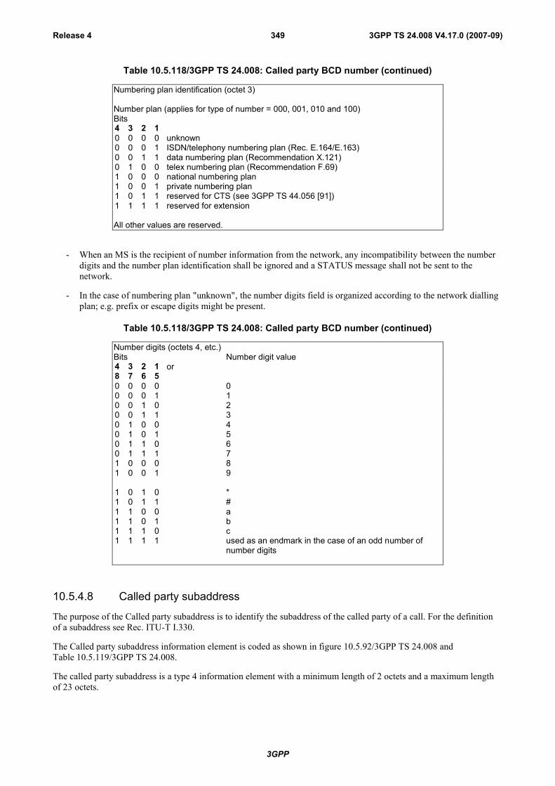
3GPP
3GPP TS 24.008 V4.17.0 (2007-09)Release 4 349
Table 10.5.118/3GPP TS 24.008: Called party BCD number (continued)
Numbering plan identification (octet 3)
Number plan (applies for type of number = 000, 001, 010 and 100)Bits4 3 2 10 0 0 0 unknown0 0 0 1 ISDN/telephony numbering plan (Rec. E.164/E.163)0 0 1 1 data numbering plan (Recommendation X.121)0 1 0 0 telex numbering plan (Recommendation F.69)1 0 0 0 national numbering plan1 0 0 1 private numbering plan1 0 1 1 reserved for CTS (see 3GPP TS 44.056 [91])1 1 1 1 reserved for extension
All other values are reserved.
- When an MS is the recipient of number information from the network, any incompatibility between the numberdigits and the number plan identification shall be ignored and a STATUS message shall not be sent to thenetwork.
- In the case of numbering plan "unknown", the number digits field is organized according to the network diallingplan; e.g. prefix or escape digits might be present.
Table 10.5.118/3GPP TS 24.008: Called party BCD number (continued)
Number digits (octets 4, etc.)Bits Number digit value4 3 2 1 or8 7 6 50 0 0 0 00 0 0 1 10 0 1 0 20 0 1 1 30 1 0 0 40 1 0 1 50 1 1 0 60 1 1 1 71 0 0 0 81 0 0 1 9
1 0 1 0 *1 0 1 1 #1 1 0 0 a1 1 0 1 b1 1 1 0 c1 1 1 1 used as an endmark in the case of an odd number of
number digits
10.5.4.8 Called party subaddress
The purpose of the Called party subaddress is to identify the subaddress of the called party of a call. For the definitionof a subaddress see Rec. ITU-T I.330.
The Called party subaddress information element is coded as shown in figure 10.5.92/3GPP TS 24.008 andTable 10.5.119/3GPP TS 24.008.
The called party subaddress is a type 4 information element with a minimum length of 2 octets and a maximum lengthof 23 octets.
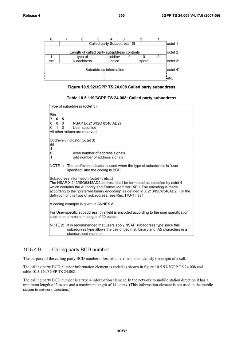
3GPP
3GPP TS 24.008 V4.17.0 (2007-09)Release 4 350
8 7 6 5 4 3 2 1Called party Subaddress IEI octet 1
Length of called party subaddress contents octet 21 type of odd/ev 0 0 0
ext subaddress Indica spare octet 3*
Subaddress information octet 4*:: etc.
Figure 10.5.92/3GPP TS 24.008 Called party subaddress
Table 10.5.119/3GPP TS 24.008: Called party subaddress
Type of subaddress (octet 3)
Bits7 6 50 0 0 NSAP (X.213/ISO 8348 AD2)0 1 0 User specifiedAll other values are reserved
Odd/even indicator (octet 3)Bit40 even number of address signals1 odd number of address signals
NOTE 1: The odd/even indicator is used when the type of subaddress is "userspecified" and the coding is BCD.
Subaddress information (octet 4, etc...)The NSAP X.213/ISO8348AD2 address shall be formatted as specified by octet 4which contains the Authority and Format Identifier (AFI). The encoding is madeaccording to the "preferred binary encoding" as defined in X.213/ISO8348AD2. For thedefinition of this type of subaddress, see Rec. ITU-T I.334.
A coding example is given in ANNEX A.
For User-specific subaddress, this field is encoded according to the user specification,subject to a maximum length of 20 octets.
NOTE 2: It is recommended that users apply NSAP subaddress type since thissubaddress type allows the use of decimal, binary and IA5 characters in astandardised manner.
10.5.4.9 Calling party BCD number
The purpose of the calling party BCD number information element is to identify the origin of a call.
The calling party BCD number information element is coded as shown in figure 10.5.93/3GPP TS 24.008 andtable 10.5.120/3GPP TS 24.008.
The calling party BCD number is a type 4 information element. In the network to mobile station direction it has aminimum length of 3 octets and a maximum length of 14 octets. (This information element is not used in the mobilestation to network direction.).
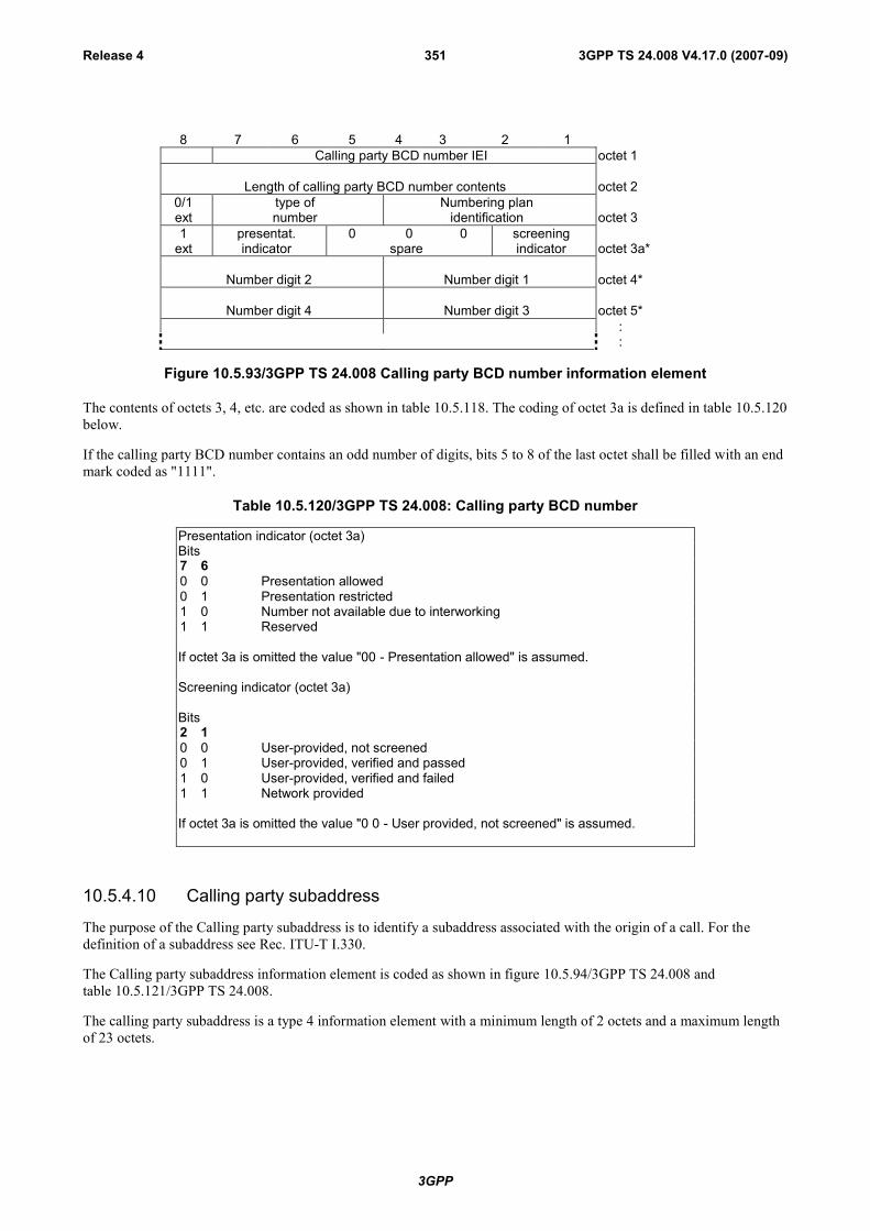
3GPP
3GPP TS 24.008 V4.17.0 (2007-09)Release 4 351
8 7 6 5 4 3 2 1Calling party BCD number IEI octet 1
Length of calling party BCD number contents octet 20/1ext
type ofnumber
Numbering planidentification octet 3
1 presentat. 0 0 0 screeningext indicator spare indicator octet 3a*
Number digit 2 Number digit 1 octet 4*
Number digit 4 Number digit 3 octet 5*::
Figure 10.5.93/3GPP TS 24.008 Calling party BCD number information element
The contents of octets 3, 4, etc. are coded as shown in table 10.5.118. The coding of octet 3a is defined in table 10.5.120below.
If the calling party BCD number contains an odd number of digits, bits 5 to 8 of the last octet shall be filled with an endmark coded as "1111".
Table 10.5.120/3GPP TS 24.008: Calling party BCD number
Presentation indicator (octet 3a)Bits7 60 0 Presentation allowed0 1 Presentation restricted1 0 Number not available due to interworking1 1 Reserved
If octet 3a is omitted the value "00 - Presentation allowed" is assumed.
Screening indicator (octet 3a)
Bits2 10 0 User-provided, not screened0 1 User-provided, verified and passed1 0 User-provided, verified and failed1 1 Network provided
If octet 3a is omitted the value "0 0 - User provided, not screened" is assumed.
10.5.4.10 Calling party subaddress
The purpose of the Calling party subaddress is to identify a subaddress associated with the origin of a call. For thedefinition of a subaddress see Rec. ITU-T I.330.
The Calling party subaddress information element is coded as shown in figure 10.5.94/3GPP TS 24.008 andtable 10.5.121/3GPP TS 24.008.
The calling party subaddress is a type 4 information element with a minimum length of 2 octets and a maximum lengthof 23 octets.

3GPP
3GPP TS 24.008 V4.17.0 (2007-09)Release 4 352
8 7 6 5 4 3 2 1Calling party Subaddress IEI octet 1
Length of calling party subaddress contents octet 21 type of odd/ev 0 0 0
ext subaddress Indica octet 3*
Subaddress information octet 4*:: etc.
Figure 10.5.94/3GPP TS 24.008 Calling party subaddress
Table 10.5.121/3GPP TS 24.008: Calling party subaddress
Type of subaddress (octet 3)
Bits7 6 50 0 0 NSAP (X.213/ISO 8348 AD2)0 1 0 User specifiedAll other values are reserved
Odd/even indicator (octet 3)Bit40 even number of address signals1 odd number of address signals
The odd/even indicator is used when the type of subaddress is "user specified" and thecoding is BCD
Subaddress information (octet 4, etc...)The NSAP X.213/ISO8348AD2 address shall be formatted as specified by octet 4which contains the Authority and Format Identifier (AFI). The encoding is madeaccording to the "preferred binary encoding" as defined in X.213/ISO8348AD2. For thedefinition of this type of this type of subaddress, see Rec. ITU-T I.332.
A coding example is given in annex A.
For User-specific subaddress, this field is encoded according to the user specification,subject to a maximum length of 20 octets.
NOTE: It is recommended that users apply NSAP subad dress type since thissubaddress type allows the use of decimal, binary and IA5 characters in astandardised manner.
10.5.4.11 Cause
The purpose of the cause information element is to describe the reason for generating certain messages, to providediagnostic information in the event of procedural errors and to indicate the location of the cause originator.
The cause information element is coded as shown in figure 10.5.95/3GPP TS 24.008 and tables 10.5.122 and10.5.123/3GPP TS 24.008.
The cause is a type 4 information element with a minimum length of 4 octets and a maximum length of 32 octets.
The cause information element may be repeated in a message.

3GPP
3GPP TS 24.008 V4.17.0 (2007-09)Release 4 353
8 7 6 5 4 3 2 1Cause IEI octet 1
Length of cause contents octet 20/1ext
codingstandard
0spare location octet 3
1ext recommendation octet 3a*1
ext cause value octet 4
diagnostic(s) if any octet 5*
octet N*
Figure 10.5.95/3GPP TS 24.008 Cause information element
If the default value applies for the recommendation field, octet 3a shall be omitted.
Table 10.5.122/3GPP TS 24.008: Cause information element
Coding standard (octet 3)Bits7 60 0 Coding as specified in ITU-T Rec. Q.9310 1 Reserved for other international standards1 0 National standard1 1 Standard defined for the GSMßPLMNS as described below and in table
10.86/3GPP TS 24.008
Coding standards other than "1 1 - Standard defined for the GSM PLMNS" shall not beused if the cause can be represented with the GSM standardized coding.
The mobile station or network need not support any other coding standard than "1 1 -Standard defined for the GSM PLMNS".If a cause IE indicating a coding standard not supported by the receiver is received,cause "interworking, unspecified" shall be assumed.
Location (octet 3)Bits4 3 2 10 0 0 0 user0 0 0 1 private network serving the local user0 0 1 0 public network serving the local user0 0 1 1 transit network0 1 0 0 public network serving the remote user0 1 0 1 private network serving the remote user0 1 1 1 international network1 0 1 0 network beyond interworking point
All other values are reserved.
Recommendation (octet 3a)Octet 3a shall not be included if the coding standard is coded as "1 1 - Standarddefined for GSM PLMNS".
If the coding standard is different from "1 1 - Standard defined for GSM PLMNS", thecoding of octet 3a, if included, and octets 4 to N is according to that coding standard.
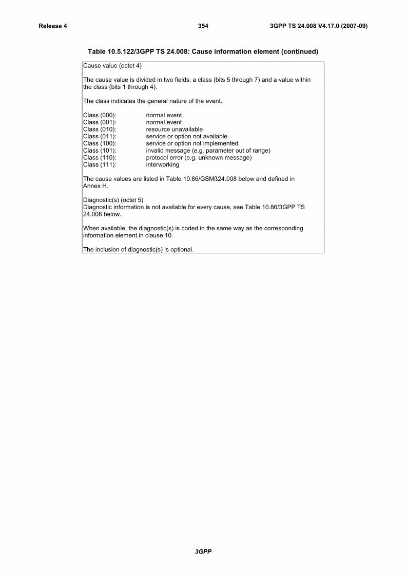
3GPP
3GPP TS 24.008 V4.17.0 (2007-09)Release 4 354
Table 10.5.122/3GPP TS 24.008: Cause information element (continued)
Cause value (octet 4)
The cause value is divided in two fields: a class (bits 5 through 7) and a value withinthe class (bits 1 through 4).
The class indicates the general nature of the event.
Class (000): normal eventClass (001): normal eventClass (010): resource unavailableClass (011): service or option not availableClass (100): service or option not implementedClass (101): invalid message (e.g. parameter out of range)Class (110): protocol error (e.g. unknown message)Class (111): interworking
The cause values are listed in Table 10.86/GSMß24.008 below and defined inAnnex H.
Diagnostic(s) (octet 5)Diagnostic information is not available for every cause, see Table 10.86/3GPP TS24.008 below.
When available, the diagnostic(s) is coded in the same way as the correspondinginformation element in clause 10.
The inclusion of diagnostic(s) is optional.

3GPP
3GPP TS 24.008 V4.17.0 (2007-09)Release 4 355
Table 10.5.123/3GPP TS 24.008: Cause information element values
Cause value Cause Cause Diag- RemarksClass Value num. nostic
7 6 5 4 3 2 1
0 0 0 0 0 0 1 1. Unassigned (unallocated) number Note 90 0 0 0 0 1 1 3. No route to destination Note 90 0 0 0 1 1 0 6. Channel unacceptable -0 0 0 1 0 0 0 8. Operator determined barring -0 0 1 0 0 0 0 16. Normal call clearing Note 90 0 1 0 0 0 1 17. User busy Note 10 0 1 0 0 1 0 18. No user responding -0 0 1 0 0 1 1 19. User alerting, no answer -0 0 1 0 1 0 1 21. Call rejected Note 9 - user supplied
diagnostic (note 4)0 0 1 0 1 1 0 22. Number changed New destination(note 5)0 0 1 1 0 0 1 25. Pre-emption0 0 1 1 0 1 0 26. Non selected user clearing -0 0 1 1 0 1 1 27. Destination out of order -0 0 1 1 1 0 0 28. Invalid number format (incomplete
number)-
0 0 1 1 1 0 1 29. Facility rejected Note 10 0 1 1 1 1 0 30. Response to STATUS ENQUIRY -0 0 1 1 1 1 1 31. Normal, unspecified -0 1 0 0 0 1 0 34. No circuit/channel available Note 10 1 0 0 1 1 0 38. Network out of order -0 1 0 1 0 0 1 41. Temporary failure -0 1 0 1 0 1 0 42. Switching equipment congestion -0 1 0 1 0 1 1 43. Access information discarded Discarded information
element identifiers(note 6)
0 1 0 1 1 0 0 44. requested circuit/channel not available -0 1 0 1 1 1 1 47. Resources unavailable, unspecified -0 1 1 0 0 0 1 49. Quality of service unavailable Note 90 1 1 0 0 1 0 50. Requested facility not subscribed Note 10 1 1 0 1 1 1 55. Incoming calls barred within the CUG Note 10 1 1 1 0 0 1 57. Bearer capability not authorized Note 30 1 1 1 0 1 0 58. Bearer capability not presently available Note 30 1 1 1 1 1 1 63. Service or option not available,
unspecified-
1 0 0 0 0 0 1 65. Bearer service not implemented Note 3
(continued)
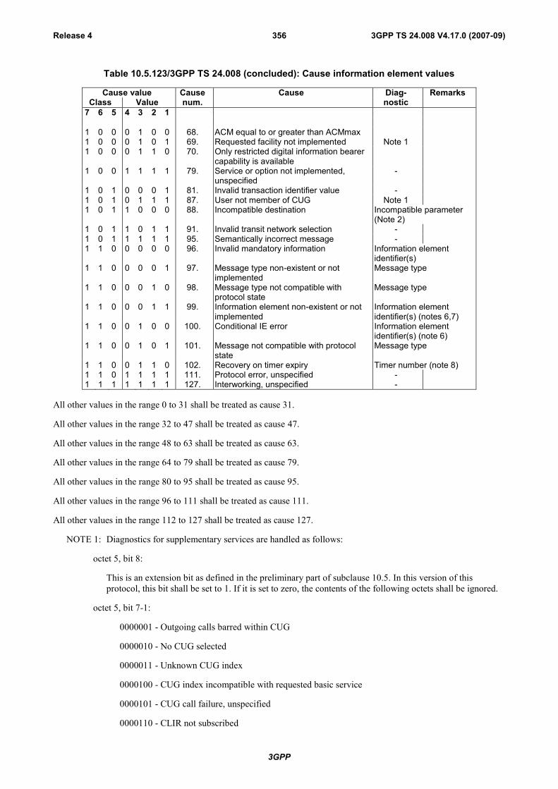
3GPP
3GPP TS 24.008 V4.17.0 (2007-09)Release 4 356
Table 10.5.123/3GPP TS 24.008 (concluded): Cause information element values
Cause value Cause Cause Diag- RemarksClass Value num. nostic
7 6 5 4 3 2 1
1 0 0 0 1 0 0 68. ACM equal to or greater than ACMmax1 0 0 0 1 0 1 69. Requested facility not implemented Note 11 0 0 0 1 1 0 70. Only restricted digital information bearer
capability is available1 0 0 1 1 1 1 79. Service or option not implemented,
unspecified-
1 0 1 0 0 0 1 81. Invalid transaction identifier value -1 0 1 0 1 1 1 87. User not member of CUG Note 11 0 1 1 0 0 0 88. Incompatible destination Incompatible parameter
(Note 2)1 0 1 1 0 1 1 91. Invalid transit network selection -1 0 1 1 1 1 1 95. Semantically incorrect message -1 1 0 0 0 0 0 96. Invalid mandatory information Information element
identifier(s)1 1 0 0 0 0 1 97. Message type non-existent or not
implementedMessage type
1 1 0 0 0 1 0 98. Message type not compatible withprotocol state
Message type
1 1 0 0 0 1 1 99. Information element non-existent or notimplemented
Information elementidentifier(s) (notes 6,7)
1 1 0 0 1 0 0 100. Conditional IE error Information elementidentifier(s) (note 6)
1 1 0 0 1 0 1 101. Message not compatible with protocolstate
Message type
1 1 0 0 1 1 0 102. Recovery on timer expiry Timer number (note 8)1 1 0 1 1 1 1 111. Protocol error, unspecified -1 1 1 1 1 1 1 127. Interworking, unspecified -
All other values in the range 0 to 31 shall be treated as cause 31.
All other values in the range 32 to 47 shall be treated as cause 47.
All other values in the range 48 to 63 shall be treated as cause 63.
All other values in the range 64 to 79 shall be treated as cause 79.
All other values in the range 80 to 95 shall be treated as cause 95.
All other values in the range 96 to 111 shall be treated as cause 111.
All other values in the range 112 to 127 shall be treated as cause 127.
NOTE 1: Diagnostics for supplementary services are handled as follows:
octet 5, bit 8:
This is an extension bit as defined in the preliminary part of subclause 10.5. In this version of thisprotocol, this bit shall be set to 1. If it is set to zero, the contents of the following octets shall be ignored.
octet 5, bit 7-1:
0000001 - Outgoing calls barred within CUG
0000010 - No CUG selected
0000011 - Unknown CUG index
0000100 - CUG index incompatible with requested basic service
0000101 - CUG call failure, unspecified
0000110 - CLIR not subscribed

3GPP
3GPP TS 24.008 V4.17.0 (2007-09)Release 4 357
0000111 - CCBS possible
0001000 - CCBS not possible
All other values shall be ignored.
NOTE 2: The incompatible parameter is composed of the incompatible information element identifier.
NOTE 3: The format of the diagnostic field for cause numbers 57, 58 and 65 is as shown in figure 10.5.88/3GPPTS 24.008 and tables 10.5.102/3GPP TS 24.008 to 10.5.115/3GPP TS 24.008.
NOTE 4: The user supplied diagnostics field is encoded according to the user specification, subject to themaximum length of the cause information element. The coding of user supplied diagnostics should bemade in such a way that it does not conflict with the coding described in note 9 below.
NOTE 5: The new destination is formatted as the called party BCD number information element, includinginformation element identifier.
NOTE 6: Locking and non-locking shift procedures described in subclause 10.5.4.2 and clause 3 are applied. Inprinciple, information element identifiers are ordered in the same order as the information elements in thereceived message.
NOTE 7: When only the locking shift information element is included and no information element identifierfollows, it means that the codeset in the locking shift itself is not implemented.
NOTE 8: The timer number is coded in IA5 characters, e.g., T308 is coded as "3" "0" "8". The following coding isused in each octet:
bit 8: spare "0"
bits 7-1: IA5 character
Octet 5 carries "3", octet 5a carries "0", etc.
NOTE 9: The following coding is used for octet 5:
bit 8 : 1
bits 7-3: 00000
bits 2-1: condition as follows:
00 - unknown
01 - permanent
10 - transient
10.5.4.11a CLIR suppression
The CLIR suppression information element may be sent by the mobile station to the network in the SETUP message.The use is defined in 3GPP TS 24.081 [25].
The CLIR suppression information element is coded as shown in figure 10.5.96/3GPP TS 24.008.
The CLIR suppression is a type 2 information element.
8 7 6 5 4 3 2 1CLIR suppression IEI octet 1
Figure 10.5.96/3GPP TS 24.008 CLIR suppression information element
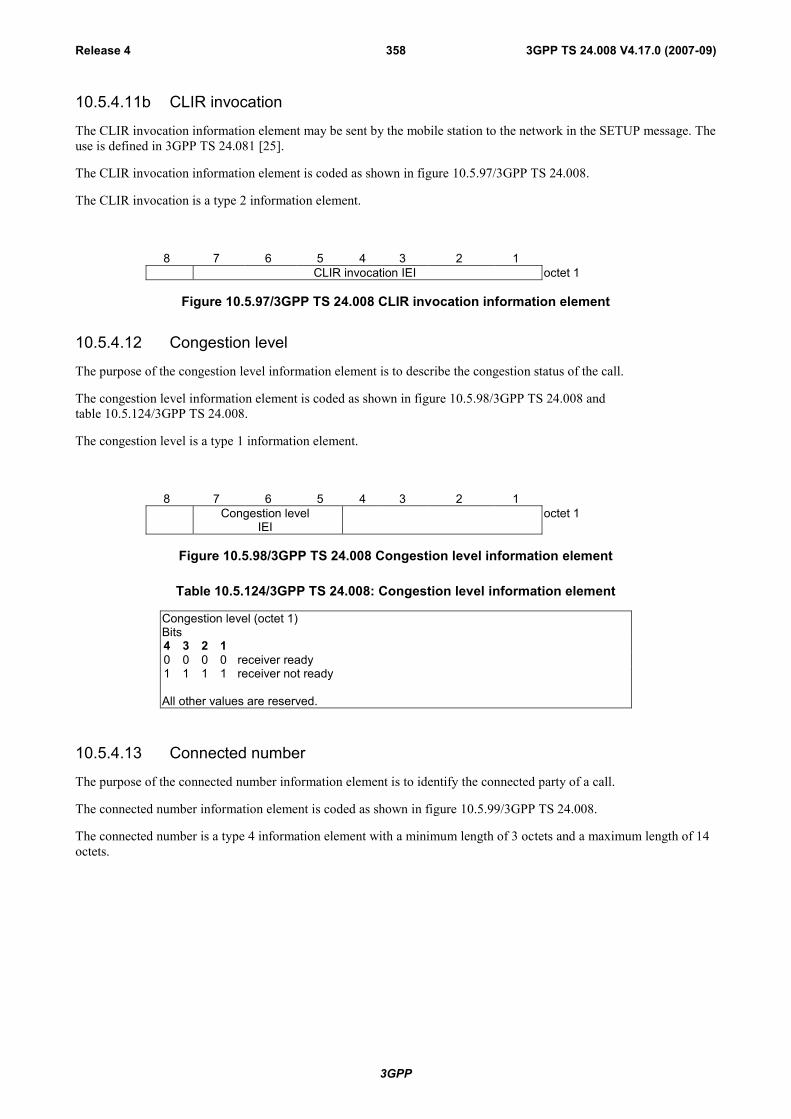
3GPP
3GPP TS 24.008 V4.17.0 (2007-09)Release 4 358
10.5.4.11b CLIR invocation
The CLIR invocation information element may be sent by the mobile station to the network in the SETUP message. Theuse is defined in 3GPP TS 24.081 [25].
The CLIR invocation information element is coded as shown in figure 10.5.97/3GPP TS 24.008.
The CLIR invocation is a type 2 information element.
8 7 6 5 4 3 2 1CLIR invocation IEI octet 1
Figure 10.5.97/3GPP TS 24.008 CLIR invocation information element
10.5.4.12 Congestion level
The purpose of the congestion level information element is to describe the congestion status of the call.
The congestion level information element is coded as shown in figure 10.5.98/3GPP TS 24.008 andtable 10.5.124/3GPP TS 24.008.
The congestion level is a type 1 information element.
8 7 6 5 4 3 2 1Congestion level
IEIoctet 1
Figure 10.5.98/3GPP TS 24.008 Congestion level information element
Table 10.5.124/3GPP TS 24.008: Congestion level information element
Congestion level (octet 1)Bits4 3 2 10 0 0 0 receiver ready1 1 1 1 receiver not ready
All other values are reserved.
10.5.4.13 Connected number
The purpose of the connected number information element is to identify the connected party of a call.
The connected number information element is coded as shown in figure 10.5.99/3GPP TS 24.008.
The connected number is a type 4 information element with a minimum length of 3 octets and a maximum length of 14octets.
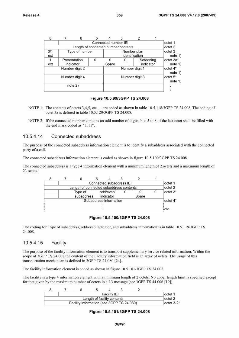
3GPP
3GPP TS 24.008 V4.17.0 (2007-09)Release 4 359
8 7 6 5 4 3 2 1Connected number IEI octet 1
Length of connected number contents octet 20/1ext
Type of number Number planidentification
octet 3note 1)
1 Presentation 0 0 0 Screening octet 3a*ext indicator Spare indicator note 1)
Number digit 2 Number digit 1 octet 4*note 1)
Number digit 4 Number digit 3 octet 5*note 1)
note 2) ::
Figure 10.5.99/3GPP TS 24.008
NOTE 1: The contents of octets 3,4,5, etc. ... are coded as shown in table 10.5.118/3GPP TS 24.008. The coding ofoctet 3a is defined in table 10.5.120/3GPP TS 24.008.
NOTE 2: If the connected number contains an odd number of digits, bits 5 to 8 of the last octet shall be filled withthe end mark coded as "1111".
10.5.4.14 Connected subaddress
The purpose of the connected subaddress information element is to identify a subaddress associated with the connectedparty of a call.
The connected subaddress information element is coded as shown in figure 10.5.100/3GPP TS 24.008.
The connected subaddress is a type 4 information element with a minimum length of 2 octets and a maximum length of23 octets.
8 7 6 5 4 3 2 1Connected subaddress IEI octet 1
Length of connected subaddress contents octet 2Type of odd/even 0 0 0 octet 3*subaddress indicator Spare
Subaddress information octet 4*:: etc.
Figure 10.5.100/3GPP TS 24.008
The coding for Type of subaddress, odd/even indicator, and subaddress information is in table 10.5.119/3GPP TS24.008.
10.5.4.15 Facility
The purpose of the facility information element is to transport supplementary service related information. Within thescope of 3GPP TS 24.008 the content of the Facility information field is an array of octets. The usage of thistransportation mechanism is defined in 3GPP TS 24.080 [24].
The facility information element is coded as shown in figure 10.5.101/3GPP TS 24.008.
The facility is a type 4 information element with a minimum length of 2 octets. No upper length limit is specified exceptfor that given by the maximum number of octets in a L3 message (see 3GPP TS 44.006 [19]).
8 7 6 5 4 3 2 1Facility IEI octet 1
Length of facility contents octet 2Facility information (see 3GPP TS 24.080) octet 3-?*
Figure 10.5.101/3GPP TS 24.008

3GPP
3GPP TS 24.008 V4.17.0 (2007-09)Release 4 360
10.5.4.16 High layer compatibility
The purpose of the high layer compatibility information element is to provide a means which should be used by theremote user for compatibility checking. See annex B.
The high layer compatibility information element is coded as shown in figure 10.5.102/3GPP TS 24.008 andtable 10.5.125/3GPP TS 24.008.
The high layer compatibility is a type 4 information element with a minimum length of 2 octets and a maximum lengthof 5 octets.
NOTE: The high layer compatibility information element is transported transparently by a PLMN between a calloriginating entity (e.g. a calling user) and the addressed entity (e.g. a remote user or a high layer functionnetwork node addressed by the call originating entity). However, if explicitly requested by the user (atsubscription time), a network which provides some capabilities to realize teleservices may interpret thisinformation to provide a particular service.
8 7 6 5 4 3 2 1High layer compatibility IEI octet 1
Length of high layer compatibility contents octet 21
extcoding
standard interpretationpresentat.method ofprotocolprofile
octet 3*
0/1ext High layer characteristics identification
octet 4*
1ext
Extended high layer characteristicsidentification
octet 4a*(note)
Figure 10.5.102/3GPP TS 24.008 High layer compatibility information element
If the value part of the IE is empty, the IE indicates "not applicable".
NOTE: Octet 4a may be present e.g. when octet 4 indicates Maintenance or Management, or audio visual.
Table 10.5.125/3GPP TS 24.008: High layer compatibility information element
Coding standard (octet 3)see ITU Recommendation Q.931.
Interpretation (octet 3)see ITU Recommendation Q.931.
Presentation method of protocol profile (octet 3)see ITU Recommendation Q.931.
High layer characteristics identification (octet 4)see ITU Recommendation Q.931.Extended high layer characteristics identification (octet 4a)see ITU Recommendation Q.931.
10.5.4.16.1 Static conditions for the high layer compatibility IE contents
Either the value part of the IE is empty, or it contains at least octet 3 and 4.
10.5.4.17 Keypad facility
The purpose of the keypad facility information element is to convey IA5 characters, e.g. entered by means of a terminalkeypad (see note).
The keypad facility information element is coded as shown in figure 10.5.103/3GPP TS 24.008.
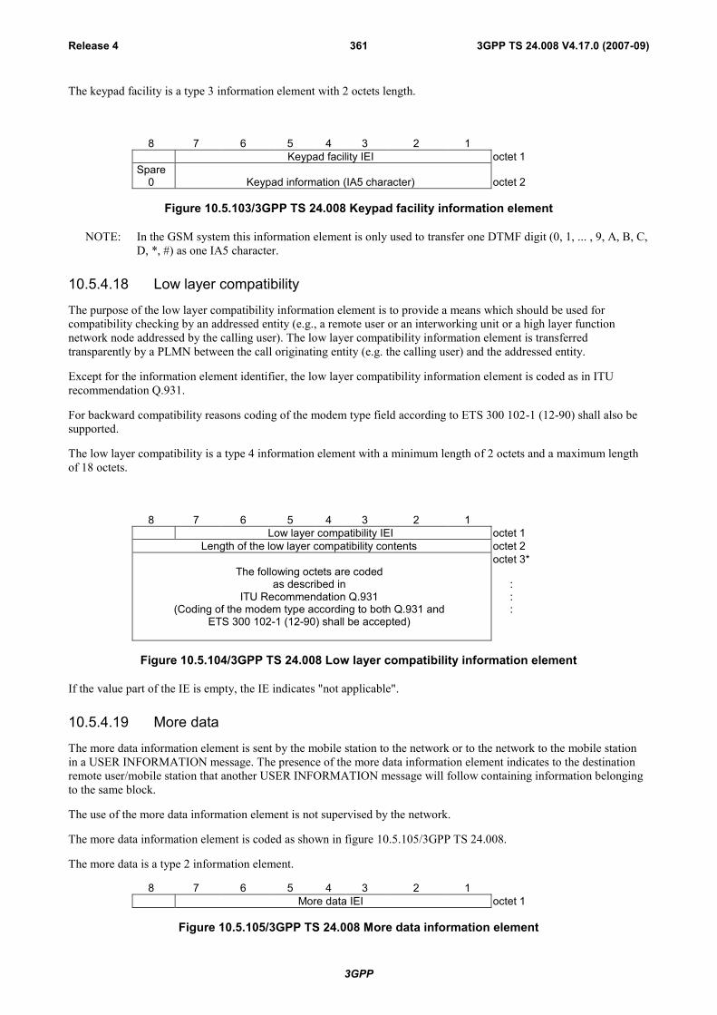
3GPP
3GPP TS 24.008 V4.17.0 (2007-09)Release 4 361
The keypad facility is a type 3 information element with 2 octets length.
8 7 6 5 4 3 2 1Keypad facility IEI octet 1
Spare0 Keypad information (IA5 character) octet 2
Figure 10.5.103/3GPP TS 24.008 Keypad facility information element
NOTE: In the GSM system this information element is only used to transfer one DTMF digit (0, 1, ... , 9, A, B, C,D, *, #) as one IA5 character.
10.5.4.18 Low layer compatibility
The purpose of the low layer compatibility information element is to provide a means which should be used forcompatibility checking by an addressed entity (e.g., a remote user or an interworking unit or a high layer functionnetwork node addressed by the calling user). The low layer compatibility information element is transferredtransparently by a PLMN between the call originating entity (e.g. the calling user) and the addressed entity.
Except for the information element identifier, the low layer compatibility information element is coded as in ITUrecommendation Q.931.
For backward compatibility reasons coding of the modem type field according to ETS 300 102-1 (12-90) shall also besupported.
The low layer compatibility is a type 4 information element with a minimum length of 2 octets and a maximum lengthof 18 octets.
8 7 6 5 4 3 2 1Low layer compatibility IEI octet 1
Length of the low layer compatibility contents octet 2
The following octets are codedas described in
ITU Recommendation Q.931(Coding of the modem type according to both Q.931 and
ETS 300 102-1 (12-90) shall be accepted)
octet 3*
:::
Figure 10.5.104/3GPP TS 24.008 Low layer compatibility information element
If the value part of the IE is empty, the IE indicates "not applicable".
10.5.4.19 More data
The more data information element is sent by the mobile station to the network or to the network to the mobile stationin a USER INFORMATION message. The presence of the more data information element indicates to the destinationremote user/mobile station that another USER INFORMATION message will follow containing information belongingto the same block.
The use of the more data information element is not supervised by the network.
The more data information element is coded as shown in figure 10.5.105/3GPP TS 24.008.
The more data is a type 2 information element.
8 7 6 5 4 3 2 1More data IEI octet 1
Figure 10.5.105/3GPP TS 24.008 More data information element

3GPP
3GPP TS 24.008 V4.17.0 (2007-09)Release 4 362
10.5.4.20 Notification indicator
The purpose of the notification indicator information element is to indicate information pertaining to a call.
The notification indicator element is coded as shown in figure 10.5.106/3GPP TS 24.008 and table 10.5.126/ 3GPP TS24.008.
The notification indicator is a type 3 information element with 2 octets length.
8 7 6 5 4 3 2 1Notification indicator IEI octet 1
1ext Notification description
octet 2
Figure 10.5.106/3GPP TS 24.008 Notification indicator information element
Table 10.5.126/3GPP TS 24.008: Notification indicator information element
Notification description (octet 2)Bits7 6 5 4 3 2 10 0 0 0 0 0 0 User suspended0 0 0 0 0 0 1 User resumed0 0 0 0 0 1 0 Bearer change
All other values are reserved.
10.5.4.21 Progress indicator
The purpose of the progress indicator information element is to describe an event which has occurred during the life ofa call.
The progress indicator information element is coded as shown in figure 10.5.107/3GPP TS 24.008 andtable 10.5.127/3GPP TS 24.008.
The progress indicator is a type 4 information element with a length of 4 octets.
8 7 6 5 4 3 2 1Progress indicator IEI octet 1
Length of progress indicator contents octet 21
extcoding
standard0
spare location octet 31
ext progress descriptionoctet 4
Figure 10.5.107/3GPP TS 24.008 Progress indicator information element

3GPP
3GPP TS 24.008 V4.17.0 (2007-09)Release 4 363
Table 10.5.127/3GPP TS 24.008: Progress indicator information element
Coding standard (octet 3)Bits7 60 0 Standardized coding, as described in ITU-T Rec. Q.9310 1 Reserved for other international standards1 0 National standard1 1 Standard defined for the GSMßPLMNS as described below
Coding standards other than "1 1 - Standard defined for the GSM PLMNS" shall not beused if the progress description can be represented with the GSMßstandardizedcoding.
The mobile station or network need not support any other coding standard than "1 1 -Standard defined for the GSM PLMNS".If a progress indicator IE indicating a coding standard not supported by the receiver isreceived, progress description "Unspecific" shall be assumed.
Location (octet 3)Bits4 3 2 10 0 0 0 User0 0 0 1 Private network serving the local user0 0 1 0 Public network serving the local user0 1 0 0 Public network serving the remote user0 1 0 1 Private network serving the remote user1 0 1 0 Network beyond interworking point
All other values are reserved.
Note: Depending on the location of the users, the local public network and remotepublic network may be the same network.
Progress description (octet 4)Bits7 6 5 4 3 2 1 No.0 0 0 0 0 0 1 1. Call is not end-to-end PLMN/ISDN, further call
progress information may be available in-band0 0 0 0 0 1 0 2. Destination address in non-PLMN/ISDN0 0 0 0 0 1 1 3. Origination address in non-PLMN/ISDN0 0 0 0 1 0 0 4. Call has returned to the PLMN/ISDN0 0 0 1 0 0 0 8. In-band information or appropriate pattern now
available0 1 0 0 0 0 0 32. Call is end-to-end PLMN/ISDN1 0 0 0 0 0 0 64. QueueingAll other values Unspecific
10.5.4.21a Recall type $(CCBS)$
The purpose of the recall type information element is to describe the reason for the recall.
The recall type information element is coded as shown in Figure 10.5.108/3GPP TS 24.008 and Table 10.5.128/3GPPTS 24.008.
The recall type is a type 3 information element with 2 octets length.
8 7 6 5 4 3 2 1recall type IEI octet 1
spare recall type0 0 0 0 0 octet 2
Figure 10.5.108/3GPP TS 24.008 Recall type information element
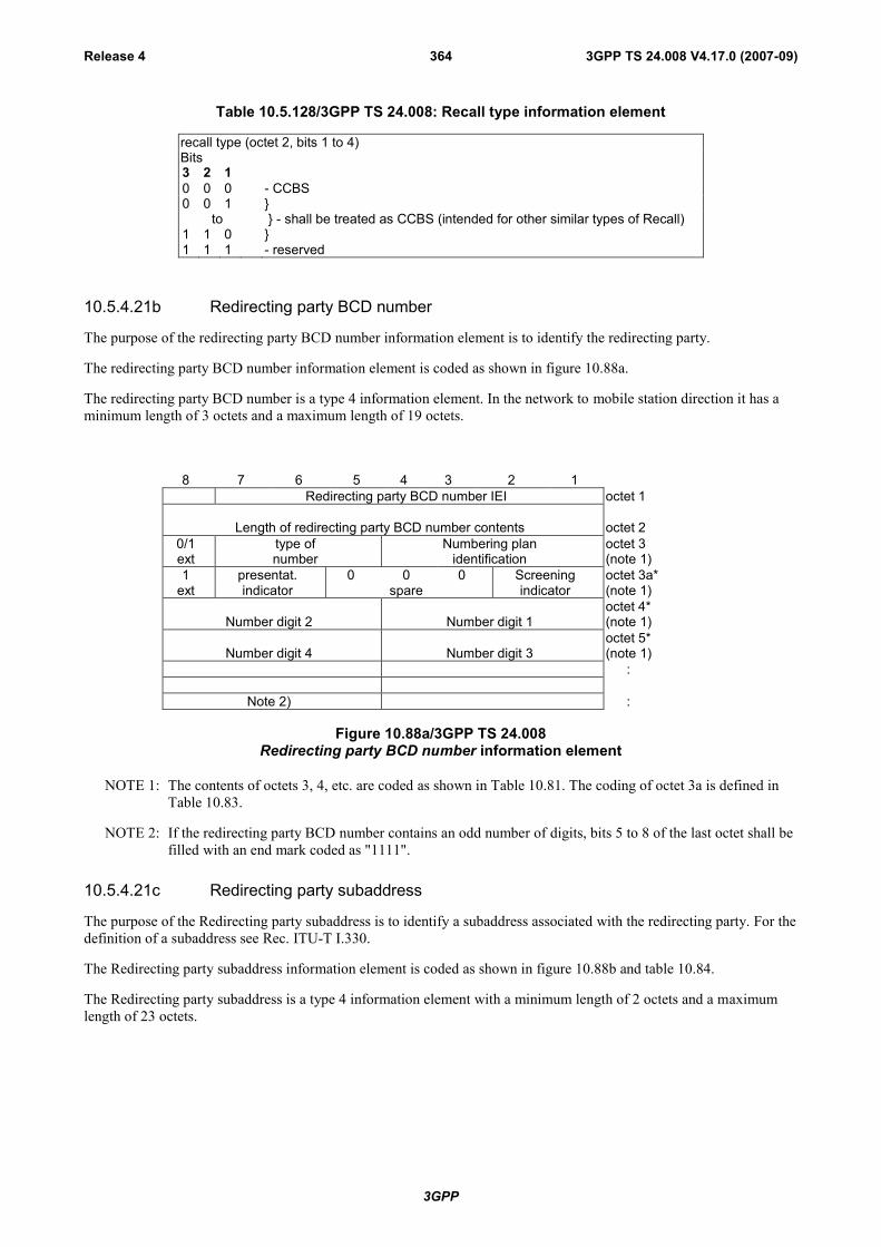
3GPP
3GPP TS 24.008 V4.17.0 (2007-09)Release 4 364
Table 10.5.128/3GPP TS 24.008: Recall type information element
recall type (octet 2, bits 1 to 4)Bits3 2 10 0 0 - CCBS0 0 1 }
to } - shall be treated as CCBS (intended for other similar types of Recall)1 1 0 }1 1 1 - reserved
10.5.4.21b Redirecting party BCD number
The purpose of the redirecting party BCD number information element is to identify the redirecting party.
The redirecting party BCD number information element is coded as shown in figure 10.88a.
The redirecting party BCD number is a type 4 information element. In the network to mobile station direction it has aminimum length of 3 octets and a maximum length of 19 octets.
8 7 6 5 4 3 2 1Redirecting party BCD number IEI octet 1
Length of redirecting party BCD number contents octet 20/1ext
type ofnumber
Numbering planidentification
octet 3(note 1)
1 presentat. 0 0 0 Screening octet 3a*ext indicator spare indicator (note 1)
Number digit 2 Number digit 1octet 4*(note 1)
Number digit 4 Number digit 3octet 5*(note 1)
:
Note 2) :
Figure 10.88a/3GPP TS 24.008Redirecting party BCD number information element
NOTE 1: The contents of octets 3, 4, etc. are coded as shown in Table 10.81. The coding of octet 3a is defined inTable 10.83.
NOTE 2: If the redirecting party BCD number contains an odd number of digits, bits 5 to 8 of the last octet shall befilled with an end mark coded as "1111".
10.5.4.21c Redirecting party subaddress
The purpose of the Redirecting party subaddress is to identify a subaddress associated with the redirecting party. For thedefinition of a subaddress see Rec. ITU-T I.330.
The Redirecting party subaddress information element is coded as shown in figure 10.88b and table 10.84.
The Redirecting party subaddress is a type 4 information element with a minimum length of 2 octets and a maximumlength of 23 octets.

3GPP
3GPP TS 24.008 V4.17.0 (2007-09)Release 4 365
8 7 6 5 4 3 2 1Redirecting party Subaddress IEI octet 1
Length of redirecting party subaddress contents octet 21
exttype of
subaddressodd/evIndica
0 0 0octet 3*
Subaddress information:
octet 4*
:etc.
Figure 10.88b/3GPP TS 24.008Redirecting party subaddress information element
10.5.4.22 Repeat indicator
The purpose of the repeat indicator information element is to indicate how the associated repeated information elementsshall be interpreted, when included in a message. The repeat indicator information element is included immediatelybefore the first occurrence of the associated information element which will be repeated in a message. "Mode 1" refersto the first occurrence of that information element, "mode 2" refers to the second occurrence of that information elementin the same message.
The repeat indicator information element is coded as shown in figure 10.5.109/3GPP TS 24.008 andtable 10.5.129/3GPP TS 24.008.
The repeat indicator is a type 1 information element.
8 7 6 5 4 3 2 1repeat indicator
IEIrepeat indication octet 1
Figure 10.5.109/3GPP TS 24.008 Repeat indicator information element
Table 10.5.129/3GPP TS 24.008: Repeat indicator information element
Repeat indication (octet 1)Bits4 3 2 10 0 0 1 Circular for successive selection
"mode 1 alternate mode 2"0 0 1 0 Support of fallback – mode 1 preferred, mode 2 selected if setup of
mode 1 fails0 0 1 1 reserved: was allocated in earlier phases of the protocolAll other values are reserved.
10.5.4.22a Reverse call setup direction
This information element may be included in a MODIFY and MODIFY COMPLETE message to indicate that thedirection of the data call to which the MODIFY message relates is opposite to the call setup direction.
The reverse call setup direction information element is coded as shown in figure 10.5.110/3GPP TS 24.008.
The reverse call setup direction is a type 2 information element
8 7 6 5 4 3 2 1reverse call setup direction IEI octet 1
Figure 10.5.110/3GPP TS 24.008 Reverse call setup direction information element

3GPP
3GPP TS 24.008 V4.17.0 (2007-09)Release 4 366
10.5.4.22b SETUP Container $(CCBS)$
This information element contains the contents of a SETUP message (Mobile Station to Network). This means that theCall Control protocol discriminator IE, the Transaction Identifier IE and the Setup message type IE are not included.
The SETUP Container information element is coded as shown in figure 10.5.111/3GPP TS 24.008.
The SETUP Container is a type 4 information. No upper length limit is specified except for that given by the maximumnumber of octets in a L3 message (see 3GPP TS 44.006 [19]).
8 7 6 5 4 3 2 1SETUP Container IEI octet 1
Length of SETUP container contents octet 2
SETUP message octet 3-n
Figure 10.5.111/3GPP TS 24.008 Octet j (j = 3, 4 ... n) is the unchanged octet j of the SETUP message.
10.5.4.23 Signal
The purpose of the signal information element is to allow the network to convey information to a user regarding tonesand alerting signals (see subclauses 5.2.2.3.2 and 7.3.3.).
The signal information element is coded as shown in figure 10.5.112/3GPP TS 24.008 andtable 10.5.130/3GPP TS 24.008.
The signal is a type 3 information element with 2 octets length.
8 7 6 5 4 3 2 1Signal IEI octet 1
Signal value octet 2
Figure 10.5.112/3GPP TS 24.008 Signal information element
Table 10.5.130/3GPP TS 24.008: Signal information element
Signal value (octet 2)Bits8 7 6 5 4 3 2 10 0 0 0 0 0 0 0 dial tone on0 0 0 0 0 0 0 1 ring back tone on0 0 0 0 0 0 1 0 intercept tone on0 0 0 0 0 0 1 1 network congestion tone on0 0 0 0 0 1 0 0 busy tone on0 0 0 0 0 1 0 1 confirm tone on0 0 0 0 0 1 1 0 answer tone on0 0 0 0 0 1 1 1 call waiting tone on0 0 0 0 1 0 0 0 off-hook warning tone on0 0 1 1 1 1 1 1 tones off0 1 0 0 1 1 1 1 alerting off
All other values are reserved.
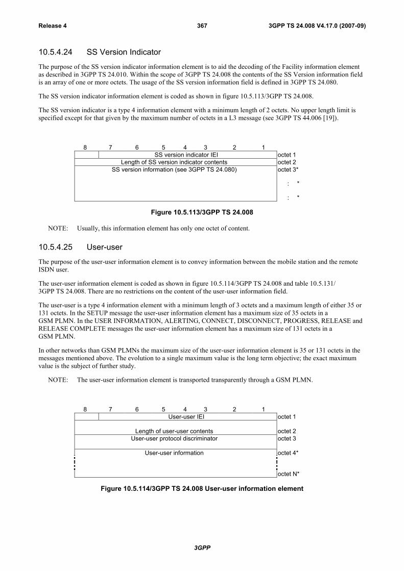
3GPP
3GPP TS 24.008 V4.17.0 (2007-09)Release 4 367
10.5.4.24 SS Version Indicator
The purpose of the SS version indicator information element is to aid the decoding of the Facility information elementas described in 3GPP TS 24.010. Within the scope of 3GPP TS 24.008 the contents of the SS Version information fieldis an array of one or more octets. The usage of the SS version information field is defined in 3GPP TS 24.080.
The SS version indicator information element is coded as shown in figure 10.5.113/3GPP TS 24.008.
The SS version indicator is a type 4 information element with a minimum length of 2 octets. No upper length limit isspecified except for that given by the maximum number of octets in a L3 message (see 3GPP TS 44.006 [19]).
8 7 6 5 4 3 2 1SS version indicator IEI octet 1
Length of SS version indicator contents octet 2SS version information (see 3GPP TS 24.080) octet 3*
: *
: *
Figure 10.5.113/3GPP TS 24.008
NOTE: Usually, this information element has only one octet of content.
10.5.4.25 User-user
The purpose of the user-user information element is to convey information between the mobile station and the remoteISDN user.
The user-user information element is coded as shown in figure 10.5.114/3GPP TS 24.008 and table 10.5.131/3GPP TS 24.008. There are no restrictions on the content of the user-user information field.
The user-user is a type 4 information element with a minimum length of 3 octets and a maximum length of either 35 or131 octets. In the SETUP message the user-user information element has a maximum size of 35 octets in aGSM PLMN. In the USER INFORMATION, ALERTING, CONNECT, DISCONNECT, PROGRESS, RELEASE andRELEASE COMPLETE messages the user-user information element has a maximum size of 131 octets in aGSM PLMN.
In other networks than GSM PLMNs the maximum size of the user-user information element is 35 or 131 octets in themessages mentioned above. The evolution to a single maximum value is the long term objective; the exact maximumvalue is the subject of further study.
NOTE: The user-user information element is transported transparently through a GSM PLMN.
8 7 6 5 4 3 2 1User-user IEI octet 1
Length of user-user contents octet 2User-user protocol discriminator octet 3
User-user information octet 4*
octet N*
Figure 10.5.114/3GPP TS 24.008 User-user information element

3GPP
3GPP TS 24.008 V4.17.0 (2007-09)Release 4 368
Table 10.5.131/3GPP TS 24.008: User-user information element
User-user protocol discriminator (octet 3)Bits8 7 6 5 4 3 2 10 0 0 0 0 0 0 0 User specific protocol (Note 1)0 0 0 0 0 0 0 1 OSI high layer protocols0 0 0 0 0 0 1 0 X.244 (Note 2)0 0 0 0 0 0 1 1 Reserved for system management convergence
function0 0 0 0 0 1 0 0 IA5 characters (Note 3)0 0 0 0 0 1 1 1 Rec.V.120 rate adaption0 0 0 0 1 0 0 0 Q.931 (I.451) user-network call control messages
0 0 0 1 0 0 0 0 Reserved for other network layer orthrough layer 3 protocols0 0 1 1 1 1 1 1
0 1 0 0 0 0 0 0through National use1 1 0 0 1 1 1 1
0 1 0 1 0 0 0 0 Reserved for other networkthrough layer or layer 3 protocols1 1 1 1 1 1 1 0
All other values are reserved.
NOTE 1: The user information is structured according to user needs.NOTE 2: The user information is structured according to Rec.X.244 which specifies
the structure of X.25 call user data.NOTE 3: The user information consists of IA5 characters.
10.5.4.26 Alerting Pattern $(NIA)$
The purpose of the Alerting Pattern information element is to allow the network to convey information related to thealert to be used by the MS (see 3GPP TS 22.101 [8]).
The Alerting Pattern information element is coded as shown in figure 10.5.115/3GPP TS 24.008 andtable 10.5.132/3GPP TS 24.008.
The Alerting Pattern IE is a type 4 information element with 3 octet length.
8 7 6 5 4 3 2 1Alerting Pattern IEI octet 1
length of alerting pattern content octet 20 0 0 0 Alerting Pattern
spare value octet 3
Figure 10.5.115/3GPP TS 24.008 Alerting Pattern information element
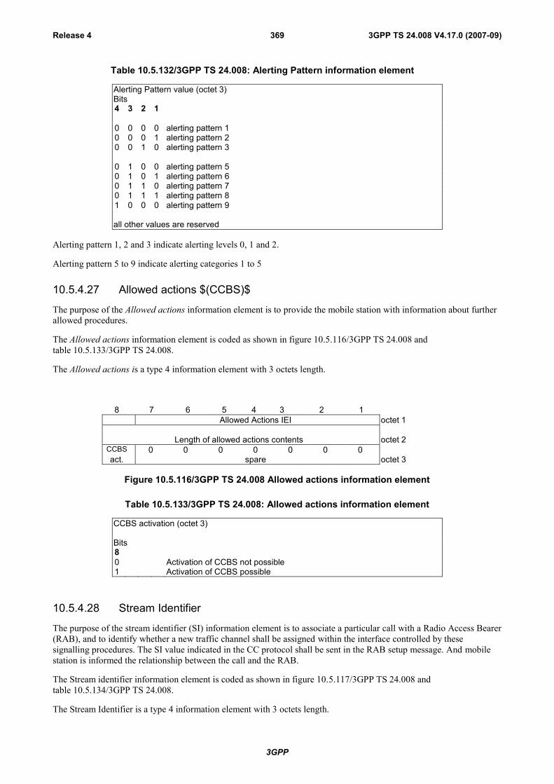
3GPP
3GPP TS 24.008 V4.17.0 (2007-09)Release 4 369
Table 10.5.132/3GPP TS 24.008: Alerting Pattern information element
Alerting Pattern value (octet 3)Bits4 3 2 1
0 0 0 0 alerting pattern 10 0 0 1 alerting pattern 20 0 1 0 alerting pattern 3
0 1 0 0 alerting pattern 50 1 0 1 alerting pattern 60 1 1 0 alerting pattern 70 1 1 1 alerting pattern 81 0 0 0 alerting pattern 9
all other values are reserved
Alerting pattern 1, 2 and 3 indicate alerting levels 0, 1 and 2.
Alerting pattern 5 to 9 indicate alerting categories 1 to 5
10.5.4.27 Allowed actions $(CCBS)$
The purpose of the Allowed actions information element is to provide the mobile station with information about furtherallowed procedures.
The Allowed actions information element is coded as shown in figure 10.5.116/3GPP TS 24.008 andtable 10.5.133/3GPP TS 24.008.
The Allowed actions is a type 4 information element with 3 octets length.
8 7 6 5 4 3 2 1Allowed Actions IEI octet 1
Length of allowed actions contents octet 2CCBS 0 0 0 0 0 0 0act. spare octet 3
Figure 10.5.116/3GPP TS 24.008 Allowed actions information element
Table 10.5.133/3GPP TS 24.008: Allowed actions information element
CCBS activation (octet 3)
Bits80 Activation of CCBS not possible1 Activation of CCBS possible
10.5.4.28 Stream Identifier
The purpose of the stream identifier (SI) information element is to associate a particular call with a Radio Access Bearer(RAB), and to identify whether a new traffic channel shall be assigned within the interface controlled by thesesignalling procedures. The SI value indicated in the CC protocol shall be sent in the RAB setup message. And mobilestation is informed the relationship between the call and the RAB.
The Stream identifier information element is coded as shown in figure 10.5.117/3GPP TS 24.008 andtable 10.5.134/3GPP TS 24.008.
The Stream Identifier is a type 4 information element with 3 octets length.

3GPP
3GPP TS 24.008 V4.17.0 (2007-09)Release 4 370
8 7 6 5 4 3 2 1Stream Identifier IEI octet 1
Length of Stream Identifier contents octet 2
Stream Identifier Value octet 3
Figure 10.5.117/3GPP TS 24.008: Stream Identifier information element
Table 10.5.134/3GPP TS 24.008: Stream Identifier information element
Stream Identifier value(octet 3)
Bit8 7 6 5 4 3 2 10 0 0 0 0 0 0 0 No bearer0 0 0 0 0 0 0 1 1
::
1 1 1 1 1 1 1 1 255
10.5.4.29 Network Call Control Capabilities
The purpose of the Network Call Control Capabilities information element is to identify the call control capabilities ofthe network. The contents might affect the manner in which the mobile station handles the call.
The Network Call Control Capabilities information element is coded as shown in figure 10.5.118/3GPP TS 24.008 andtable 10.5.135/3GPP TS 24.008.
The Network Call Control Capabilities is a type 4 information element with a length of 3 octets.
8 7 6 5 4 3 2 1Network Call Control Capabilities IEI octet 1
Length of NW Call Control Cap. contents octet 20 0 0 0 0 0 0
spare MCS octet 3
Figure 10.5.118/3GPP TS 24.008 Network Call Control Capabilities information element
Table 10.5.135/3GPP TS 24.008: Network Call Control Capabilities
MCS (octet 3, bit 1)0 This value indicates that the network does not support the multicall.1 This value indicates that the network supports the multicall.
10.5.4.30 Cause of No CLI
Cause of No CLI information element provides the mobile station the detailed reason why Calling party BCD number isnot notified (see 3GPP TS 24.081 [25]).
The Cause of No CLI information element is coded as shown in figure 10.5.118a/3GPP TS 24.008 andtable 10.5.135a/3GPP TS 24.008.
The Cause of No CLI is a type 4 information element with the length of 3 octets.
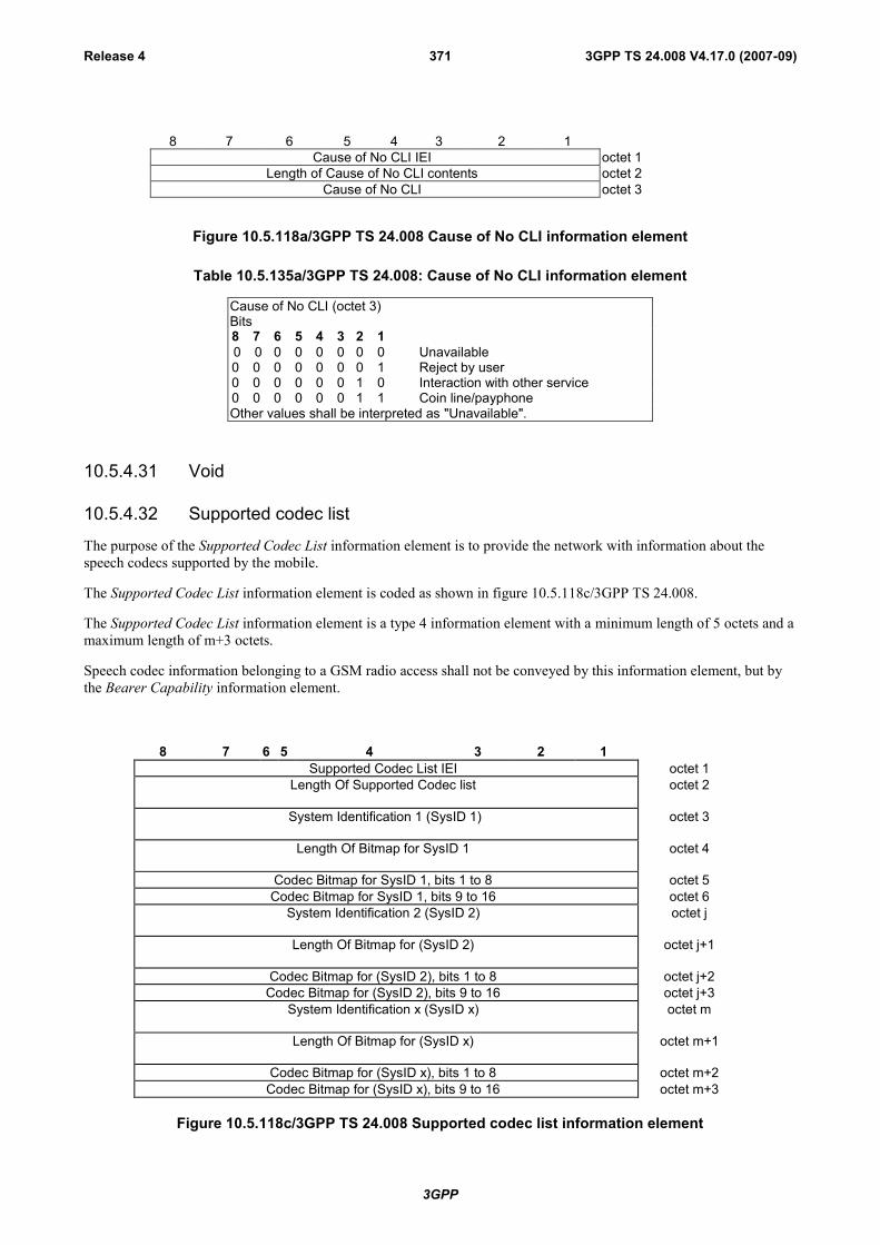
3GPP
3GPP TS 24.008 V4.17.0 (2007-09)Release 4 371
8 7 6 5 4 3 2 1Cause of No CLI IEI octet 1
Length of Cause of No CLI contents octet 2Cause of No CLI octet 3
Figure 10.5.118a/3GPP TS 24.008 Cause of No CLI information element
Table 10.5.135a/3GPP TS 24.008: Cause of No CLI information element
Cause of No CLI (octet 3)Bits8 7 6 5 4 3 2 10 0 0 0 0 0 0 0 Unavailable0 0 0 0 0 0 0 1 Reject by user0 0 0 0 0 0 1 0 Interaction with other service0 0 0 0 0 0 1 1 Coin line/payphoneOther values shall be interpreted as "Unavailable".
10.5.4.31 Void
10.5.4.32 Supported codec list
The purpose of the Supported Codec List information element is to provide the network with information about thespeech codecs supported by the mobile.
The Supported Codec List information element is coded as shown in figure 10.5.118c/3GPP TS 24.008.
The Supported Codec List information element is a type 4 information element with a minimum length of 5 octets and amaximum length of m+3 octets.
Speech codec information belonging to a GSM radio access shall not be conveyed by this information element, but bythe Bearer Capability information element.
8 7 6 5 4 3 2 1Supported Codec List IEI octet 1
Length Of Supported Codec list octet 2
System Identification 1 (SysID 1) octet 3
Length Of Bitmap for SysID 1 octet 4
Codec Bitmap for SysID 1, bits 1 to 8 octet 5Codec Bitmap for SysID 1, bits 9 to 16 octet 6
System Identification 2 (SysID 2) octet j
Length Of Bitmap for (SysID 2) octet j+1
Codec Bitmap for (SysID 2), bits 1 to 8 octet j+2Codec Bitmap for (SysID 2), bits 9 to 16 octet j+3
System Identification x (SysID x) octet m
Length Of Bitmap for (SysID x) octet m+1
Codec Bitmap for (SysID x), bits 1 to 8 octet m+2Codec Bitmap for (SysID x), bits 9 to 16 octet m+3
Figure 10.5.118c/3GPP TS 24.008 Supported codec list information element
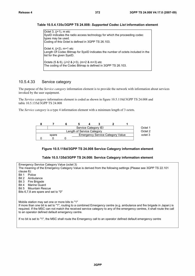
3GPP
3GPP TS 24.008 V4.17.0 (2007-09)Release 4 372
Table 10.5.4.135c/3GPP TS 24.008: Supported Codec List information element
Octet 3, (j+1), m etcSysID indicates the radio access technology for which the proceeding codectypes may be used.Coding of this Octet is defined in 3GPP TS 26.103.
Octet 4, (j+2), m+1 etcLength Of Codec Bitmap for SysID indicates the number of octets included in thelist for the given SysID.
Octets (5 & 6), (J+2 & j+3), (m+2 & m+3) etcThe coding of the Codec Bitmap is defined in 3GPP TS 26.103.
10.5.4.33 Service category
The purpose of the Service category information element is to provide the network with information about servicesinvoked by the user equipment.
The Service category information element is coded as shown in figure 10.5.118d/3GPP TS 24.008 andtable 10.5.135d/3GPP TS 24.008
The Service category is a type 4 information element with a minimum length of 3 octets.
8 7 6 5 4 3 2 1Service Category IEI Octet 1
Length of Service Category Octet 2spare Emergency Service Category Value
0 0 0octet 3
Figure 10.5.118d/3GPP TS 24.008 Service Category information element
Table 10.5.135d/3GPP TS 24.008: Service Category information element
Emergency Service Category Value (octet 3)The meaning of the Emergency Category Value is derived from the following settings (Please see 3GPP TS 22.101clause 8):Bit 1 PoliceBit 2 AmbulanceBit 3 Fire BrigadeBit 4 Marine GuardBit 5 Mountain RescueBits 6,7,8 are spare and set to "0"
Mobile station may set one or more bits to "1"If more than one bit is set to "1", routing to a combined Emergency centre (e.g. ambulance and fire brigade in Japan) isrequired. If the MSC can not match the received service category to any of the emergency centres, it shall route the callto an operator defined default emergency centre.
If no bit is set to "1", the MSC shall route the Emergency call to an operator defined default emergency centre
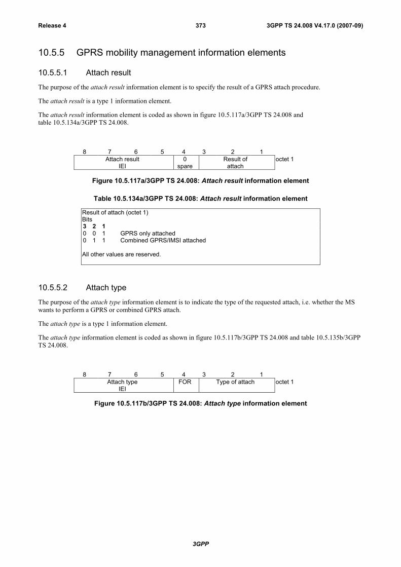
3GPP
3GPP TS 24.008 V4.17.0 (2007-09)Release 4 373
10.5.5 GPRS mobility management information elements
10.5.5.1 Attach result
The purpose of the attach result information element is to specify the result of a GPRS attach procedure.
The attach result is a type 1 information element.
The attach result information element is coded as shown in figure 10.5.117a/3GPP TS 24.008 andtable 10.5.134a/3GPP TS 24.008.
8 7 6 5 4 3 2 1Attach result
IEI0
spareResult of
attachoctet 1
Figure 10.5.117a/3GPP TS 24.008: Attach result information element
Table 10.5.134a/3GPP TS 24.008: Attach result information element
Result of attach (octet 1)Bits3 2 10 0 1 GPRS only attached0 1 1 Combined GPRS/IMSI attached
All other values are reserved.
10.5.5.2 Attach type
The purpose of the attach type information element is to indicate the type of the requested attach, i.e. whether the MSwants to perform a GPRS or combined GPRS attach.
The attach type is a type 1 information element.
The attach type information element is coded as shown in figure 10.5.117b/3GPP TS 24.008 and table 10.5.135b/3GPPTS 24.008.
8 7 6 5 4 3 2 1Attach type
IEIFOR Type of attach octet 1
Figure 10.5.117b/3GPP TS 24.008: Attach type information element

3GPP
3GPP TS 24.008 V4.17.0 (2007-09)Release 4 374
Table 10.5.135b/3GPP TS 24.008: Attach type information element
Type of attach (octet 1, bit 1 to 3)Bits3 2 10 0 1 GPRS attach0 1 0 GPRS attach while IMSI attached0 1 1 Combined GPRS/IMSI attach
All other values are interpreted as GPRS attach in this version of the protocol.
Follow-on request (octet 1, bit 4)Bits40 No follow-on request pending1 Follow-on request pendingFollow-on request pending is applicable only in UMTS.
10.5.5.3 Ciphering algorithm
The purpose of the ciphering algorithm information element is to specify which ciphering algorithm shall be used.
The ciphering algorithm is a type 1 information element.
The ciphering algorithm information element is coded as shown in figure 10.5.119/3GPP TS 24.008 andtable 10.5.136/3GPP TS 24.008.
8 7 6 5 4 3 2 1Ciphering algorithm
IEI0
spareType of
algorithmoctet 1
Figure 10.5.119/3GPP TS 24.008: Ciphering algorithm information element
Table 10.5.136/3GPP TS 24.008: Ciphering algorithm information element
Type of ciphering algorithm (octet 1)Bits3 2 10 0 0 ciphering not used0 0 1 GPRS Encryption Algorithm GEA/10 1 0 GPRS Encryption Algorithm GEA/20 1 1 GPRS Encryption Algorithm GEA/31 0 0 GPRS Encryption Algorithm GEA/41 0 1 GPRS Encryption Algorithm GEA/51 1 0 GPRS Encryption Algorithm GEA/61 1 1 GPRS Encryption Algorithm GEA/7
10.5.5.4 TMSI status
The purpose of the TMSI status information element is to indicate whether a valid TMSI is available in the MS or not.
The TMSI status is a type 1 information element.
The TMSI status information element is coded as shown in figure 10.5.120/3GPP TS 24.008 andtable 10.5.137/3GPP TS 24.008.
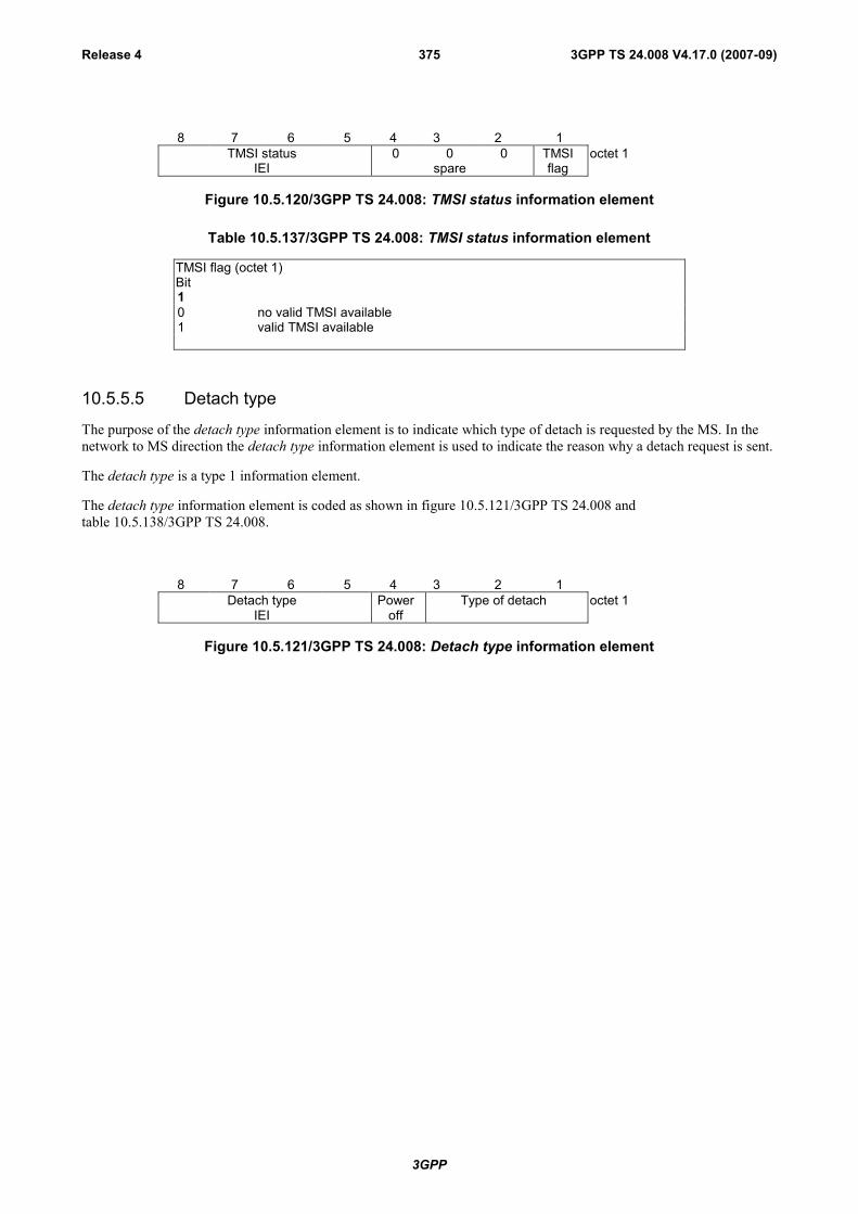
3GPP
3GPP TS 24.008 V4.17.0 (2007-09)Release 4 375
8 7 6 5 4 3 2 1TMSI status 0 0 0 TMSI octet 1
IEI spare flag
Figure 10.5.120/3GPP TS 24.008: TMSI status information element
Table 10.5.137/3GPP TS 24.008: TMSI status information element
TMSI flag (octet 1)Bit10 no valid TMSI available1 valid TMSI available
10.5.5.5 Detach type
The purpose of the detach type information element is to indicate which type of detach is requested by the MS. In thenetwork to MS direction the detach type information element is used to indicate the reason why a detach request is sent.
The detach type is a type 1 information element.
The detach type information element is coded as shown in figure 10.5.121/3GPP TS 24.008 andtable 10.5.138/3GPP TS 24.008.
8 7 6 5 4 3 2 1Detach type
IEIPower
offType of detach octet 1
Figure 10.5.121/3GPP TS 24.008: Detach type information element

3GPP
3GPP TS 24.008 V4.17.0 (2007-09)Release 4 376
Table 10.5.138/3GPP TS 24.008: Detach type information element
Type of detach (octet 1)
In the MS to network direction:Bits3 2 10 0 1 GPRS detach0 1 0 IMSI detach0 1 1 Combined GPRS/IMSI detach
All other values are interpreted as Combined GPRS/IMSI detach by this version of theprotocol.
In the network to MS direction:Bits3 2 10 0 1 re-attach required0 1 0 re-attach not required0 1 1 IMSI detach (after VLR failure)
All other values are interpreted as re-attach not required by this version of the protocol.
Power off (octet 1)
In the MS to network direction:Bit40 normal detach1 power switched off
In the network to MS direction the Power off bit shall be spare and set to zero.
10.5.5.6 DRX parameter
The purpose of the DRX parameter information element is to indicate whether the MS uses DRX mode or not.
The DRX parameter is a type 3 information element with a length of 3 octets.
The value part of a DRX parameter information element is coded as shown in table 10.5.139/3GPP TS 24.008.
8 7 6 5 4 3 2 1DRX parameter IEI octet 1
SPLIT PG CYCLE CODE octet 2CN Specific DRX cycle length
coefficientSPLIT
onCCCH
non-DRXtimer octet 3
Figure 10.5.122/3GPP TS 24.008: DRX parameter information element

3GPP
3GPP TS 24.008 V4.17.0 (2007-09)Release 4 377
Table 10.5.139/3GPP TS 24.008: DRX parameter information element
SPLIT PG CYCLE CODE, octet 2The octet contains the binary coded value of the SPLIT PG CYCLE CODE. The SPLITPG CYCLE value is derived from the SPLIT PG CYCLE CODE as follows:
0 704 (equivalent to no DRX)1 to 64 1 to 64, respectively65 7166 7267 7468 7569 7770 7971 8072 8373 8674 8875 9076 9277 9678 10179 10380 10781 11282 11683 11884 12885 14186 14487 15088 16089 17190 17691 19292 21493 22494 23595 25696 28897 32098 352
All other values are reserved and shall be interpreted as 1 by this version of theprotocol.
SPLIT on CCCH, octet 3 (bit 4)
0 Split pg cycle on CCCH is not supported by the mobile station1 Split pg cycle on CCCH is supported by the mobile station
non-DRX timer, octet 3bit3 2 10 0 0 no non-DRX mode after transfer state0 0 1 max. 1 sec non-DRX mode after transfer state0 1 0 max. 2 sec non-DRX mode after transfer state0 1 1 max. 4 sec non-DRX mode after transfer state1 0 0 max. 8 sec non-DRX mode after transfer state1 0 1 max. 16 sec non-DRX mode after transfer state1 1 0 max. 32 sec non-DRX mode after transfer state1 1 1 max. 64 sec non-DRX mode after transfer state

3GPP
3GPP TS 24.008 V4.17.0 (2007-09)Release 4 378
CN Specific DRX cycle length coefficient, octet 3bit8 7 6 5 UMTS specific0 0 0 0 CN Specific DRX cycle length coefficient not specified by the MS, ie. the
system information value 'CN domain specific DRX cycle length' is used.(Ref 3GPP TS 25.331)
0 1 1 0 CN Specific DRX cycle length coefficient 60 1 1 1 CN Specific DRX cycle length coefficient 71 0 0 0 CN Specific DRX cycle length coefficient 81 0 0 1 CN Specific DRX cycle length coefficient 9
All other values shall be interpreted as "CN Specific DRX cycle length coefficient notspecified by the MS " by this version of the protocol.
NOTE: In UMTS this field (octet 3 bits 8 to 5) is used, but was spare in earlierversions of this protocol.
10.5.5.7 Force to standby
The purpose of the force to standby information element is to force the MS to stop the READY timer in order to preventthe MS to perform cell updates.
In UMTS, the network shall always indicate force to standby not indicated in the force to standby information element.
The force to standby is a type 1 information element.
The force to standby information element is coded as shown in figure 10.5.123/3GPP TS 24.008 andtable 10.5.140/3GPP TS 24.008.
8 7 6 5 4 3 2 1Force to standby
IEI0
spareForce to
standby valueoctet 1
Figure 10.5.123/3GPP TS 24.008: Force to standby information element
Table 10.5.140/3GPP TS 24.008: Force to standby information element
Force to standby value (octet 1)
Bits3 2 10 0 0 Force to standby not indicated0 0 1 Force to standby indicated
All other values are interpreted asforce to standby not indicated by this version of the protocol.
10.5.5.8 P-TMSI signature
The purpose of the P-TMSI signature information element is to identify a GMM context of an MS.
The P-TMSI signature is a type 3 information element with 4 octets length.
The P-TMSI signature information element is coded as shown in figure 10.5.124/3GPP TS 24.008 andtable 10.5.141/3GPP TS 24.008.

3GPP
3GPP TS 24.008 V4.17.0 (2007-09)Release 4 379
8 7 6 5 4 3 2 1P-TMSI signature IEI octet 1
P-TMSI signature valueoctet 2
octet 4
Figure 10.5.124/3GPP TS 24.008: P-TMSI signature information element
Table 10.5.141/3GPP TS 24.008: P-TMSI signature information element
P-TMSI signature valueOctets 2, 3 and 4 contain the binary representation of the P-TMSI signature.
Bit 1 of octet 4 is the least significant bit and bit 8 of octet 2 is the most significant bit.
10.5.5.8a P-TMSI signature 2
The purpose of the P-TMSI signature 2 information element is to identify a GMM context of an MS.
The P-TMSI signature 2 is a type 4 information element with 5 octets length.
The P-TMSI signature 2 information element is coded as shown in figure 10.5.124a/3GPP TS 24.008 andtable 10.5.141a/3GPP TS 24.008.
8 7 6 5 4 3 2 1P-TMSI signature 2 IEI octet 1
Length of P-TMSI signature 2 contents octet 2
P-TMSI signature 2 valueoctet 3
octet 5
Figure 10.5.124a/3GPP TS 24.008: P-TMSI signature 2 information element
Table 10.5.141a/3GPP TS 24.008: P-TMSI signature 2 information element
P-TMSI signature 2 value is coded as octets 2 to 4 of the P-TMSI signature IE.
10.5.5.9 Identity type 2
The purpose of the identity type 2 information element is to specify which identity is requested.
The identity type 2 is a type 1 information element.
The identity type 2 information element is coded as shown in figure 10.5.125/3GPP TS 24.008 and table 10.5.142/3GPPTS 24.008.
8 7 6 5 4 3 2 1Identity type 2
IEI0
spareType ofidentity
octet 1
Figure 10.5.125/3GPP TS 24.008: Identity type 2 information element
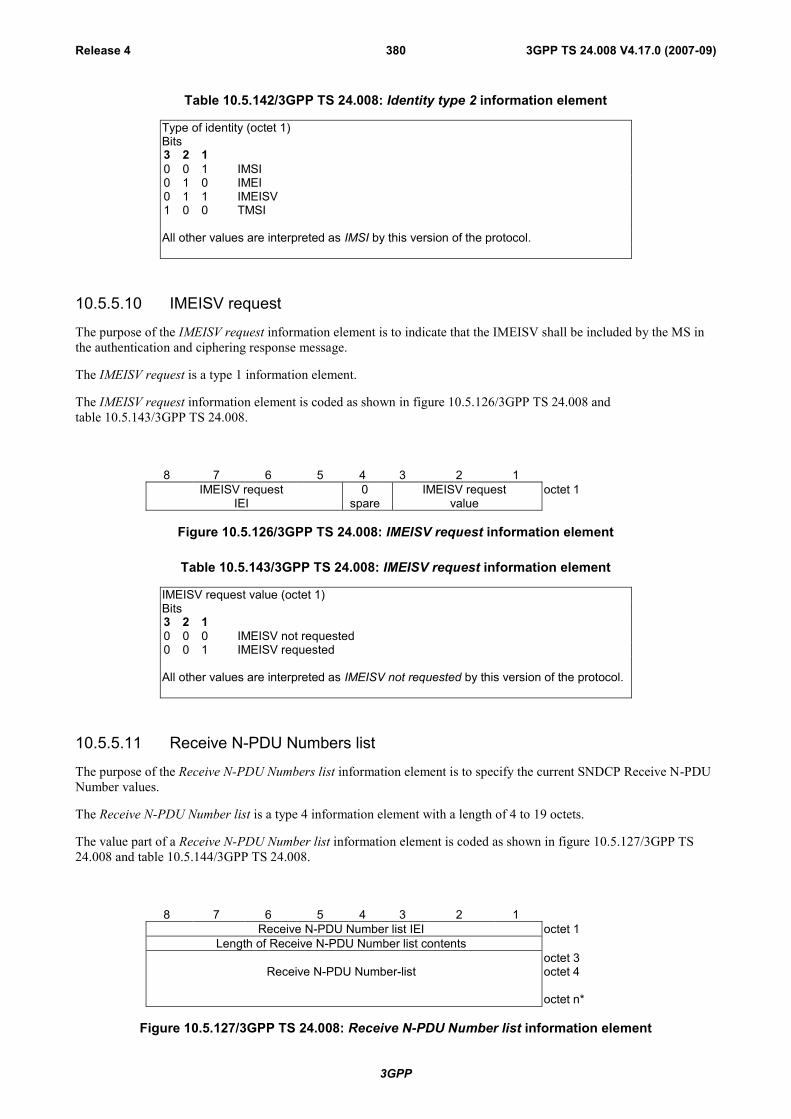
3GPP
3GPP TS 24.008 V4.17.0 (2007-09)Release 4 380
Table 10.5.142/3GPP TS 24.008: Identity type 2 information element
Type of identity (octet 1)Bits3 2 10 0 1 IMSI0 1 0 IMEI0 1 1 IMEISV1 0 0 TMSI
All other values are interpreted as IMSI by this version of the protocol.
10.5.5.10 IMEISV request
The purpose of the IMEISV request information element is to indicate that the IMEISV shall be included by the MS inthe authentication and ciphering response message.
The IMEISV request is a type 1 information element.
The IMEISV request information element is coded as shown in figure 10.5.126/3GPP TS 24.008 andtable 10.5.143/3GPP TS 24.008.
8 7 6 5 4 3 2 1IMEISV request
IEI0
spareIMEISV request
valueoctet 1
Figure 10.5.126/3GPP TS 24.008: IMEISV request information element
Table 10.5.143/3GPP TS 24.008: IMEISV request information element
IMEISV request value (octet 1)Bits3 2 10 0 0 IMEISV not requested0 0 1 IMEISV requested
All other values are interpreted as IMEISV not requested by this version of the protocol.
10.5.5.11 Receive N-PDU Numbers list
The purpose of the Receive N-PDU Numbers list information element is to specify the current SNDCP Receive N-PDUNumber values.
The Receive N-PDU Number list is a type 4 information element with a length of 4 to 19 octets.
The value part of a Receive N-PDU Number list information element is coded as shown in figure 10.5.127/3GPP TS24.008 and table 10.5.144/3GPP TS 24.008.
8 7 6 5 4 3 2 1Receive N-PDU Number list IEI octet 1
Length of Receive N-PDU Number list contents
Receive N-PDU Number-listoctet 3octet 4
octet n*
Figure 10.5.127/3GPP TS 24.008: Receive N-PDU Number list information element

3GPP
3GPP TS 24.008 V4.17.0 (2007-09)Release 4 381
Table 10.5.144/3GPP TS 24.008: Receive N-PDU Number list information element
Receive N-PDU Number -list value ::=
{ < Receive N-PDU Number -list > < Padding bits>} ;
< Receive N-PDU Number-list > ::= < sapi : bit-string(4) > < Receive N-PDUNumber-value : bit-string(8) > { < Receive N-PDU Number-list> | < null > } ;
< nsapi > ::={ 0101 }; |-- NSAPI 5{ 0110 }; | -- NSAPI 6{ 0111 }; | -- NSAPI 7{ 1000 }; | -- NSAPI 8{ 1001 }; | -- NSAPI 9{ 1010 }; | -- NSAPI 10{ 1011 }; | -- NSAPI 11{ 1100 }; | -- NSAPI 12{ 1101 }; | -- NSAPI 13{ 1110 }; | -- NSAPI 14{ 1111 }; -- NSAPI 15
< Receive N-PDU Number-value > ::= { 0 | 1} (8) ;-- Contains the binary coded representation of the receive N-PDU Number value.-- The first bit in transmission order is the most significant bit.
<Padding bits> ::= null | 0000;
10.5.5.12 MS network capability
The purpose of the MS network capability information element is to provide the network with information concerningaspects of the mobile station related to GPRS. The contents might affect the manner in which the network handles theoperation of the mobile station. The MS network capability information indicates general mobile station characteristicsand it shall therefore, except for fields explicitly indicated, be independent of the frequency band of the channel it issent on.
The MS network capability is a type 4 information element with a maximum of 10 octets length.
The value part of a MS network capabilityinformation element is coded as shown in figure 10.5.128/3GPP TS 24.008and table 10.5.145/3GPP TS 24.008.
8 7 6 5 4 3 2 1MS network capability IEI octet 1
Length of MS network capability contents octet 2MS network capability value octet 3-10
Figure 10.5.128/3GPP TS 24.008 MS network capability information element

3GPP
3GPP TS 24.008 V4.17.0 (2007-09)Release 4 382
Table 10.5.145/3GPP TS 24.008 MS network capability information element
<MS network capability value part> ::=
<GEA1 bits><SM capabilities via dedicated channels: bit><SM capabilities via GPRS channels: bit><UCS2 support: bit><SS Screening Indicator: bit string(2)><SoLSA Capability : bit><Revision level indicator: bit><PFC feature mode: bit><Extended GEA bits>< LCS VA capability: bit ><Spare bits>;
<GEA1 bits> ::= < GEA/1 :bit>;
<Extended GEA bits> ::= <GEA/2:bit><GEA/3:bit>< GEA/4:bit >< GEA/5:bit >< GEA/6:bit ><GEA/7:bit>;
<Spare bits> ::= null | {<spare bit> < Spare bits >};
SS Screening Indicator0 0 defined in 3GPP TS 24.080
0 1 defined in 3GPP TS 24.0801 0 defined in 3GPP TS 24.0801 1 defined in 3GPP TS 24.080
SM capabilities via dedicated channels0 Mobile station does not support mobile terminated point to point SMS via
dedicated signalling channels1 Mobile station supports mobile terminated point to point SMS via dedicated
signalling channels
SM capabilities via GPRS channels0 Mobile station does not support mobile terminated point to point SMS via
GPRS packet data channels1 Mobile station supports mobile terminated point to point SMS via GPRS
packet data channels
UCS2 supportThis information field indicates the likely treatment by the mobile station of UCS2 encoded character strings.
0 the ME has a preference for the default alphabet (defined in 3GPP TS 23.038 [8b])over UCS2.
1 the ME has no preference between the use of the default alphabet and theuse of UCS2.
GPRS Encryption Algorithm GEA/10 encryption algorithm GEA/1not available1 encryption algorithm GEA/1 available
SoLSA Capability0 The ME does not support SoLSA.1 The ME supports SoLSA.
Revision level indicator0 used by a mobile station not supporting R99 or later versions of the protocol1 used by a mobile station supporting R99 or later versions of the protocol
PFC feature mode0 Mobile station does not support BSS packet flow procedures1 Mobile station does support BSS packet flow procedures

3GPP
3GPP TS 24.008 V4.17.0 (2007-09)Release 4 383
GEA/20 encryption algorithm GEA/2 not available1 encryption algorithm GEA/2 available
GEA/30 encryption algorithm GEA/3 not available1 encryption algorithm GEA/3 available
GEA/40 encryption algorithm GEA/4 not available1 encryption algorithm GEA/4 available
GEA/50 encryption algorithm GEA/5 not available1 encryption algorithm GEA/5 available
GEA/60 encryption algorithm GEA/6 not available1 encryption algorithm GEA/6 available
GEA/70 encryption algorithm GEA/7 not available1 encryption algorithm GEA/7 available
LCS VA capability (LCS value added location request notification capability)This information field indicates the support of the LCS value added location request notification via PS domain asdefined in 3GPP TS 23.271 [96].
0 location request notification via PS domain not supported1 location request notification via PS domain supported
10.5.5.12a MS Radio Access capability
The purpose of the MS RA capability information element is to provide the radio part of the network with informationconcerning radio aspects of the mobile station. The contents might affect the manner in which the network handles theoperation of the mobile station.
The MS RA capability is a type 4 information element, with a maximum length of 52 octets.
The value part of a MS RA capability information element is coded a shown table 10.5.146/3GPP TS 24.008.
For the indication of the Access Technology Types the following conditions shall apply:
- Among the three Access Type Technologies GSM 900-P, GSM 900-E and GSM 900-R only one shall bepresent.
- Due to shared radio frequency channel numbers between GSM 1800 and GSM 1900, the mobile station shouldprovide the relevant radio access capability for either GSM 1800 band OR GSM 1900 band, not both.
- The MS shall indicate its supported Access Technology Types during a single MM procedure.
- If the alternative coding by using the Additional access technologies struct is chosen by the mobile station, themobile station shall indicate its radio access capability for the serving BCCH frequency band in the first includedAccess capabilities struct.
- The first Access Technology Type shall not be set to "1111".
For error handling the following shall apply:
If a received Access Technology Type is unknown to the receiver, it shall ignore all the corresponding fields.
If within a known Access Technology Type a receiver recognizes an unknown field it shall ignore it.

3GPP
3GPP TS 24.008 V4.17.0 (2007-09)Release 4 384
For more details about error handling of MS radio access capability see 3GPP TS 48.018 [86].
Table 10.5.146/3GPP TS 24.008: Mobile Station Radio Access Capability Information Element
< MS Radio Access capability IE > ::=<MS Radio Access capability IEI : 00100100 ><Length of MS RA capability: <octet>> -- length in octets of MS RA capability value part and spare bits<MS RA capability value part : < MS RA capability value part struct >><spare bits>**; -- may be used for future enhancements
<MS RA capability value part struct >::= --recursive structure allows any number of Access technologies{ { < Access Technology Type: bit (4) exclude 1111 >
< Access capabilities : <Access capabilities struct> > }
| { < Access Technology Type: bit (4) == 1111 > -- structure adding Access technologies with samecapabilities
< Length : bit (7) > -- length in bits of list of Additional access technologies and spare bits{ 1 < Additional access technologies: < Additional access technologies struct > > } ** 0<spare bits>** } }
{ 0 | 1 <MS RA capability value part struct> } ;
< Additional access technologies struct > ::=< Access Technology Type : bit (4) >< GMSK Power Class : bit (3) >< 8PSK Power Class : bit (2) > ;
< Access capabilities struct > ::=< Length : bit (7) > -- length in bits of Content and spare bits<Access capabilities : <Content>><spare bits>** ; -- expands to the indicated length
-- may be used for future enhancements
< Content > ::=< RF Power Capability : bit (3) >{ 0 | 1 <A5 bits : <A5 bits> > } -- zero means that the same values apply for parameters as in the immediately
preceding Access capabilities field within this IE< ES IND : bit >< PS : bit >< VGCS : bit >< VBS : bit >{ 0 | 1 < Multislot capability : Multislot capability struct > } -- zero means that the same values for multislot
parameters as given in an earlier Access capabilities field within this IE apply also here-- Additions in release 99
{ 0 | 1 < 8PSK Power Capability : bit(2) >} -- '1' also means 8PSK modulation capability in uplink.< COMPACT Interference Measurement Capability : bit >< Revision Level Indicator : bit >< UMTS FDD Radio Access Technology Capability : bit > -- 3G RAT< UMTS 3.84 Mcps TDD Radio Access Technology Capability : bit > -- 3G RAT< CDMA 2000 Radio Access Technology Capability : bit > -- 3G RAT
-- Additions in release 4< UMTS 1.28 Mcps TDD Radio Access Technology Capability: bit > -- 3G RAT< GERAN Feature Package 1 : bit >{ 0 | 1 < Extended DTM GPRS Multi Slot Class : bit(2) >
< Extended DTM EGPRS Multi Slot Class : bit(2) > }< Modulation based multislot class support : bit > ;-- error: struct too short, assume features do not exist-- error: struct too long, ignore data and jump to next Access technology

3GPP
3GPP TS 24.008 V4.17.0 (2007-09)Release 4 385
Table 10.5.146/3GPP TS 24.008 (continued): Mobile Station Radio Access Capability IE
< Multislot capability struct > ::={ 0 | 1 < HSCSD multislot class : bit (5) > }{ 0 | 1 < GPRS multislot class : bit (5) > < GPRS Extended Dynamic Allocation Capability : bit > }{ 0 | 1 < SMS_VALUE : bit (4) > < SM_VALUE : bit (4) > }
-- Additions in release 99{ 0 | 1 < ECSD multislot class : bit (5) > }{ 0 | 1 < EGPRS multislot class : bit (5) > < EGPRS Extended Dynamic Allocation Capability : bit > }{0 | 1 < DTM GPRS Multi Slot Class: bit(2)>
<Single Slot DTM : bit>{0 | 1 <DTM EGPRS Multi Slot Class : bit(2)> } } ;
-- error: struct too short, assume features do not exist
<A5 bits> ::= < A5/1 : bit> <A5/2 : bit> <A5/3 : bit> <A5/4 : bit> <A5/5 : bit> <A5/6 : bit> <A5/7 : bit>; -- bits for circuitmode ciphering algorithms. These fields are not used by the network and may be excluded by the MS.
Access Technology TypeThis field indicates the access technology type to be associated with the following access capabilities.Bits4 3 2 10 0 0 0 GSM P0 0 0 1 GSM E --note that GSM E covers GSM P0 0 1 0 GSM R --note that GSM R covers GSM E and GSM P0 0 1 1 GSM 18000 1 0 0 GSM 19000 1 0 1 GSM 4500 1 1 0 GSM 4800 1 1 1 GSM 8501 0 0 0 GSM 7501 1 1 1 Indicates the presence of a list of Additional access technologiesAll other values are treated as unknown by the receiver.
A MS which does not support any GSM access technology type shall set this field to '0000'.
RF Power Capability, GMSK Power Class (3 bit field)This field contains the binary coding of the power class used for GMSK associated with the indicated AccessTechnology Type (see 3GPP TS 45.005).
A MS which does not support any GSM access technology type shall set this field to '000'.
8PSK Power Capability (2 bit field)If 8-PSK modulation is supported for uplink, this field indicates the radio capability for 8-PSK modulation. Thefollowing coding is used (see 3GPP TS 45.005 [33]):Bits 2 1
0 0 Reserved0 1 Power class E11 0 Power class E21 1 Power class E3
8PSK Power Class (2 bit field)This field indicates the radio capability for 8-PSK modulation. The following coding is used (see 3GPP TS 45.005):Bits 2 1
0 0 8PSK modulation not supported for uplink0 1 Power class E11 0 Power class E21 1 Power class E3
Additional access technologies structThis structure contains the GMSK Power Class and 8PSK Power Class for an additional Access Technology. Allother capabilities for this indicated Access Technology are the same as the capabilities indicated by the precedingAccess capabilities struct.
A5/10 encryption algorithm A5/1 not available1 encryption algorithm A5/1 availableA5/2

3GPP
3GPP TS 24.008 V4.17.0 (2007-09)Release 4 386
0 encryption algorithm A5/2 not available1 encryption algorithm A5/2 availableA5/30 encryption algorithm A5/3 not available1 encryption algorithm A5/3 availableA5/40 encryption algorithm A5/4 not available1 encryption algorithm A5/4 availableA5/50 encryption algorithm A5/5 not available1 encryption algorithm A5/5 availableA5/60 encryption algorithm A5/6 not available1 encryption algorithm A5/6 availableA5/70 encryption algorithm A5/7 not available1 encryption algorithm A5/7 available
ES IND – (Controlled early Classmark Sending)0 "controlled early Classmark Sending" option is not implemented1 "controlled early Classmark Sending" option is implemented

3GPP
3GPP TS 24.008 V4.17.0 (2007-09)Release 4 387
Table 10.5.146/3GPP TS 24.008 (concluded): Mobile Station Radio Access Capability IE
PS – (Pseudo Synchronisation)0 PS capability not present1 PS capability present
VGCS – (Voice Group Call Service)0 no VGCS capability or no notifications wanted1 VGCS capability and notifications wanted.
VBS – (Voice Broadcast Service)0 no VBS capability or no notifications wanted1 VBS capability and notifications wanted
HSCSD Multi Slot ClassThe Multi Slot Class field is coded as the binary representation of the multislot class defined in 3GPP TS 45.002 [32].This field is not used by the network and may be excluded by the MS.Range 1 to 18, all other values are reserved.
GPRS Multi Slot ClassThe GPRS Multi Slot Class field is coded as the binary representation of the multislot class defined in 3GPP TS45.002 [32].
ECSD Multi Slot ClassThe presence of this field indicates ECSD capability. Whether the MS is capable of 8-PSK modulation in uplink isindicated by the presence of 8-PSK Power Capability field. The Multi Slot Class field is coded as the binaryrepresentation of the multislot class defined in 3GPP TS 45.002 [32]. This field is not used by the network and maybe excluded by the MS.Range 1 to 18, all other values are reserved.
EGPRS Multi Slot ClassThe presence of this field indicates EGPRS capability. Whether the MS is capable of 8-PSK modulation in uplink isindicated by the presence of 8-PSK Power Capability field. The EGPRS Multi Slot Class field is coded as the binaryrepresentation of the multislot class defined in 3GPP TS 45.002 [32].
GPRS Extended Dynamic Allocation Capability0 Extended Dynamic Allocation Capability for GPRS is not implemented1 Extended Dynamic Allocation Capability for GPRS is implemented
EGPRS Extended Dynamic Allocation Capability0 Extended Dynamic Allocation Capability for EGPRS is not implemented1 Extended Dynamic Allocation Capability for EGPRS is implemented
SMS_VALUE (Switch-Measure-Switch) (4 bit field)The SMS field indicates the time needed for the mobile station to switch from one radio channel to another, perform aneighbor cell power measurement, and the switch from that radio channel to another radio channel. This field is notused by the network and may be excluded by the MS.Bits4 3 2 10 0 0 0 1/4 timeslot (~144 microseconds)0 0 0 1 2/4 timeslot (~288 microseconds)0 0 1 0 3/4 timeslot (~433 microseconds) . . .1 1 1 1 16/4 timeslot (~2307 microseconds)
(SM_VALUE) Switch-Measure (4 bit field)The SM field indicates the time needed for the mobile station to switch from one radio channel to another andperform a neighbour cell power measurement. This field is not used by the network and may be excluded by the MS.Bits4 3 2 10 0 0 0 1/4 timeslot (~144 microseconds)0 0 0 1 2/4 timeslot (~288 microseconds)0 0 1 0 3/4 timeslot (~433 microseconds) . . .1 1 1 1 16/4 timeslot (~2307 microseconds)

3GPP
3GPP TS 24.008 V4.17.0 (2007-09)Release 4 388
DTM GPRS Multi Slot Class (2 bit field)This field indicates the DTM GPRS multislot capabilities of the MS. It is coded as follows:Bits2 10 0 Unused. If received, the network shall interpret this as ‘01’0 1 Multislot class 5 supported1 0 Multislot class 9 supported1 1 Multislot class 11 supported
Single Slot DTM (1 bit field)This field indicates whether the MS supports single slot DTM operation (see 3GPP TS 43.055 [87]).Bit10 Single Slot DTM not supported1 Single Slot DTM supported
An MS indicating support for Extended DTM GPRS multislot class or Extended DTM EGPRS multislot class shallset this bit to ‘1’. The network may ignore the bit in this case.
DTM EGPRS Multi Slot Class (2 bit field)This field indicates the DTM EGPRS multislot capabilities of the MS. This field shall be included only if the mobilestation supports DTM EGPRS. This field is coded as the DTM GPRS multislot Class field.
COMPACT Interference Measurement Capability (1 bit field)Bit0 COMPACT Interference Measurement Capability is not implemented1 COMPACT Interference Measurement Capability is implemented
Revision Level Indicator (1 bit field)Bit0 The ME is Release ’98 or older1 The ME is Release ’99 onwards
UMTS FDD Radio Access Technology Capability (1 bit field)Bit0 UMTS FDD not supported1 UMTS FDD supported
UMTS 3.84 Mcps TDD Radio Access Technology Capability (1 bit field)Bit0 UMTS 3.84 Mcps TDD not supported1 UMTS 3.84 Mcps TDD supported
CDMA 2000 Radio Access Technology Capability (1 bit field)Bit0 CDMA2000 not supported1 CDMA2000 supported
UMTS 1.28 Mcps TDD Radio Access Technology Capability (1 bit field)Bit0 UMTS 1.28 Mcps TDD not supported1 UMTS 1.28 Mcps TDD supported
GERAN Feature Package 1 (1 bit field)This field indicates whether the MS supports the GERAN Feature Package 1 (see 3GPP TS 44.060). It is coded asfollows:Bit0 GERAN feature package 1 not supported.1 GERAN feature package 1 supported.
DTM Extended GPRS Multi Slot Class (2 bit field)This field indicates the extended DTM GPRS capabilities of the MS and shall be interpreted in conjunction with theDTM GPRS Multi Slot Class field. It is coded as follows, where ‘DGMSC’ denotes the DTM GPRS multislot classfield:DGMSC Bit 2 1 Bit 2 1
0 0 0 0 Unused. If received, it shall be interpreted as ‘01 00’0 0 0 1 Unused. If received, it shall be interpreted as ‘01 00’0 0 1 0 Unused. If received, it shall be interpreted as ‘01 00’

3GPP
3GPP TS 24.008 V4.17.0 (2007-09)Release 4 389
0 0 1 1 Unused. If received, it shall be interpreted as ‘01 00’0 1 0 0 Multislot class 5 supported0 1 0 1 Multislot class 6 supported0 1 1 0 Unused. If received, it shall be interpreted as ‘01 00’0 1 1 1 Unused. If received, it shall be interpreted as ‘01 00’1 0 0 0 Multislot class 9 supported1 0 0 1 Multislot class 10 supported1 0 1 0 Unused. If received, it shall be interpreted as ’10 00’1 0 1 1 Unused. If received, it shall be interpreted as ’10 00’1 1 0 0 Multislot class 11 supported1 1 0 1 Unused. If received, it shall be interpreted as ’11 00’1 1 1 0 Unused. If received, it shall be interpreted as ’11 00’1 1 1 1 Unused. If received, it shall be interpreted as ’11 00’
The presence of this field indicates that the MS supports combined fullrate and halfrate GPRS channels in thedownlink. When this field is not present, the MS supports the multislot class indicated by the DTM GPRS Multi SlotClass field.
Extended DTM EGPRS Multislot Class (2 bit field)This field is not considered when the DTM EGPRS Multislot Class field is not included. This field indicates theextended DTM EGPRS multislot capabilities of the MS and shall be interpreted in conjunction with the DTM EGPRSMultislot Class field. This field is coded as the Extended DTM GPRS Multislot Class field. The presence of this fieldindicates that the MS supports combined fullrate and halfrate GPRS channels in the downlink. When this field is notpresent, the MS supports the multislot class indicated by the DTM EGPRS Multi Slot Class field.
Modulation based multislot class support (1 bit field)Bit0 "Modulation based multislot class" not supported1 "Modulation based multislot class" supported
10.5.5.13 Spare
This is intentionally left spare.
10.5.5.14 GMM cause
The purpose of the GMM cause information element is to indicate the reason why a GMM request from the mobilestation is rejected by the network.
The GMM cause information element is coded as shown in figure 10.5.129/3GPP TS 24.008 and table 10.5.147/3GPPTS 24.008.
The GMM cause is a type 3 information element with 2 octets length.
8 7 6 5 4 3 2 1GMM cause IEI octet 1
Cause value octet 2
Figure 10.5.129/3GPP TS 24.008: GMM cause information element

3GPP
3GPP TS 24.008 V4.17.0 (2007-09)Release 4 390
Table 10.5.147/3GPP TS 24.008: GMM cause information element
Cause value (octet 2)Bits8 7 6 5 4 3 2 10 0 0 0 0 0 1 0 IMSI unknown in HLR0 0 0 0 0 0 1 1 Illegal MS0 0 0 0 0 1 1 0 Illegal ME0 0 0 0 0 1 1 1 GPRS services not allowed0 0 0 0 1 0 0 0 GPRS services and non-GPRS services not
allowed0 0 0 0 1 0 0 1 MS identity cannot be derived by the network0 0 0 0 1 0 1 0 Implicitly detached0 0 0 0 1 0 1 1 PLMN not allowed0 0 0 0 1 1 0 0 Location Area not allowed0 0 0 0 1 1 0 1 Roaming not allowed in this location area0 0 0 0 1 1 1 0 GPRS services not allowed in this PLMN0 0 0 0 1 1 1 1 No Suitable Cells In Location Area0 0 0 1 0 0 0 0 MSC temporarily not reachable0 0 0 1 0 0 0 1 Network failure0 0 0 1 0 1 0 0 MAC failure0 0 0 1 0 1 0 1 Synch failure0 0 0 1 0 1 1 0 Congestion0 0 0 1 0 1 1 1 GSM authentication unacceptable0 0 1 0 1 0 0 0 No PDP context activated0 0 1 1 0 0 0 0 }
to } retry upon entry into a new cell0 0 1 1 1 1 1 1 }0 1 0 1 1 1 1 1 Semantically incorrect message0 1 1 0 0 0 0 0 Invalid mandatory information0 1 1 0 0 0 0 1 Message type non-existent or not implemented0 1 1 0 0 0 1 0 Message type not compatible with the protocol
state0 1 1 0 0 0 1 1 Information element non-existent or not
implemented0 1 1 0 0 1 0 0 Conditional IE error0 1 1 0 0 1 0 1 Message not compatible with the protocol state0 1 1 0 1 1 1 1 Protocol error, unspecified
Any other value received by the mobile station shall be treated as 0110 1111, "Protocolerror, unspecified". Any other value received by the network shall be treated as 01101111, "Protocol error, unspecified".
NOTE: The listed reject cause values are defined in annex G.
10.5.5.15 Routing area identification
The purpose of the routing area identification information element is to provide an unambiguous identification ofrouting areas within the GPRS coverage area.
The routing area identification is a type 3 information element with 7 octets length.
The routing area identification information element is coded as shown in figure 10.5.130/3GPP TS 24.008 andtable 10.5.148/3GPP TS 24.008.

3GPP
3GPP TS 24.008 V4.17.0 (2007-09)Release 4 391
8 7 6 5 4 3 2 1Routing Area Identification IEI octet 1
MCC digit 2 MCC digit 1 octet 2MNC digit 3 MCC digit 3 octet 3MNC digit 2 MNC digit 1 octet 4
LAC octet 5LAC cont'd octet 6
RAC octet 7
Figure 10.5.130/3GPP TS 24.008: Routing area identification information element
Table 10.5.148/3GPP TS 24.008: Routing area identification information element
MCC, Mobile country code (octet 2 and 3)
The MCC field is coded as in ITU-T Rec. E212, Annex A.If the RAI is deleted, the MCC and MNC shall take the value from the deleted RAI.
In abnormal cases, the MCC stored in the mobile station can contain elements not in the set {0, 1 ... 9}. In suchcases the mobile station should transmit the stored values using full hexadecimal encoding. When receiving suchan MCC, the network shall treat the RAI as deleted.
MNC, Mobile network code (octet 3 bits 5 to 8, octet 4)
The coding of this field is the responsibility of each administration but BCD coding shall be used. The MNC shallconsist of 2 or 3 digits. For PCS 1900 for NA, Federal regulation mandates that a 3-digit MNC shall be used.However a network operator may decide to use only two digits in the MNC in the RAI over the radio interface. Inthis case, bits 5 to 8 of octet 3 shall be coded as "1111". Mobile equipment shall accept RAI coded in such a way.
NOTE 1: In earlier versions of this protocol, the possibility to use a one digit MNC in RAI was provided on theradio interface. However as this was not used this possibility has been deleted.
NOTE 2: In earlier versions of this protocol, bits 5 to 8 of octet 3 were coded as "1111". Mobile equipmentcompliant with these earlier versions of the protocol may be unable to understand the 3-digit MNCformat of the RAI, and therefore unable to register on a network broadcasting the RAI in this format.
In abnormal cases, the MNC stored in the mobile station can have:- digit 1 or 2 not in the set {0, 1 ... 9}, or- digit 3 not in the set {0, 1 ...9, F} hex.In such cases the mobile station shall transmit the stored values using full hexadecimal encoding. Whenreceiving such an MNC, the network shall treat the RAI as deleted.
The same handling shall apply for the network, if a 3-digit MNC is sent by the mobile station to a network usingonly a 2-digit MNC.
LAC, Location area code (octet 5 and 6)
In the LAC field bit 8 of octet 5 is the most significant bit and bit 1 of octet 6 the least significant bit.The coding of the location area code is the responsibility of each administration except that two values are usedto mark the LAC, and hence the RAI, as deleted. Coding using full hexadecimal representation may be used. Thelocation area code consists of 2 octets.If a RAI has to be deleted then all bits of the location area code shall be set to one with the exception of the leastsignificant bit which shall be set to zero. If a SIM is inserted in a Mobile Equipment with the location area codecontaining all zeros, then the Mobile Equipment shall recognise this LAC as part of a deleted RAI.
RAC, Routing area code (octet 7)
In the RAC field bit 8 of octet 7 is the most significant. The coding of the routing area code is the responsibility ofeach administration. Coding using full hexadecimal representation may be used. The routing area code consistsof 1 octet.
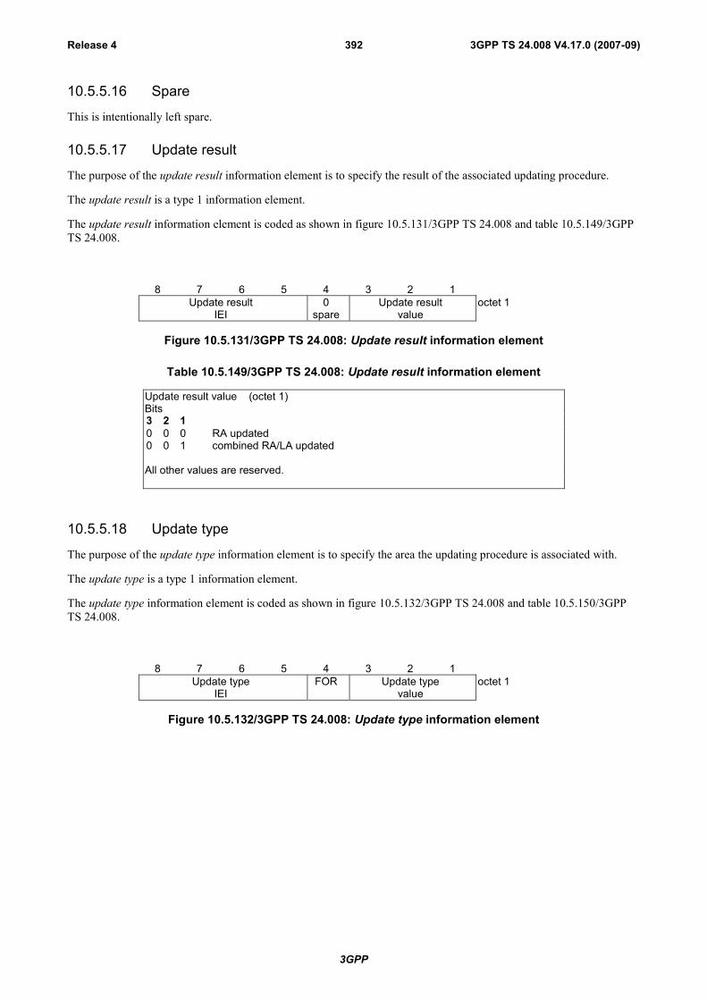
3GPP
3GPP TS 24.008 V4.17.0 (2007-09)Release 4 392
10.5.5.16 Spare
This is intentionally left spare.
10.5.5.17 Update result
The purpose of the update result information element is to specify the result of the associated updating procedure.
The update result is a type 1 information element.
The update result information element is coded as shown in figure 10.5.131/3GPP TS 24.008 and table 10.5.149/3GPPTS 24.008.
8 7 6 5 4 3 2 1Update result
IEI0
spareUpdate result
valueoctet 1
Figure 10.5.131/3GPP TS 24.008: Update result information element
Table 10.5.149/3GPP TS 24.008: Update result information element
Update result value (octet 1)Bits3 2 10 0 0 RA updated0 0 1 combined RA/LA updated
All other values are reserved.
10.5.5.18 Update type
The purpose of the update type information element is to specify the area the updating procedure is associated with.
The update type is a type 1 information element.
The update type information element is coded as shown in figure 10.5.132/3GPP TS 24.008 and table 10.5.150/3GPPTS 24.008.
8 7 6 5 4 3 2 1Update type
IEIFOR Update type
valueoctet 1
Figure 10.5.132/3GPP TS 24.008: Update type information element
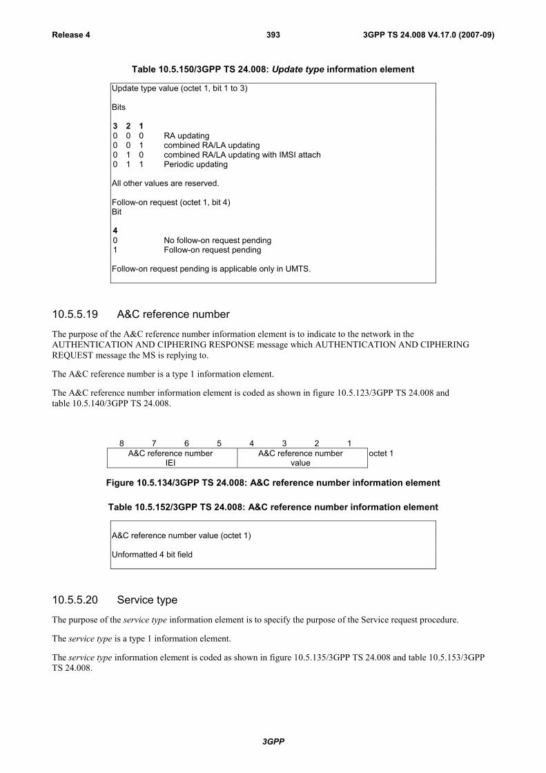
3GPP
3GPP TS 24.008 V4.17.0 (2007-09)Release 4 393
Table 10.5.150/3GPP TS 24.008: Update type information element
Update type value (octet 1, bit 1 to 3)
Bits
3 2 10 0 0 RA updating0 0 1 combined RA/LA updating0 1 0 combined RA/LA updating with IMSI attach0 1 1 Periodic updating
All other values are reserved.
Follow-on request (octet 1, bit 4)Bit
40 No follow-on request pending1 Follow-on request pending
Follow-on request pending is applicable only in UMTS.
10.5.5.19 A&C reference number
The purpose of the A&C reference number information element is to indicate to the network in theAUTHENTICATION AND CIPHERING RESPONSE message which AUTHENTICATION AND CIPHERINGREQUEST message the MS is replying to.
The A&C reference number is a type 1 information element.
The A&C reference number information element is coded as shown in figure 10.5.123/3GPP TS 24.008 andtable 10.5.140/3GPP TS 24.008.
8 7 6 5 4 3 2 1A&C reference number
IEIA&C reference number
valueoctet 1
Figure 10.5.134/3GPP TS 24.008: A&C reference number information element
Table 10.5.152/3GPP TS 24.008: A&C reference number information element
A&C reference number value (octet 1)
Unformatted 4 bit field
10.5.5.20 Service type
The purpose of the service type information element is to specify the purpose of the Service request procedure.
The service type is a type 1 information element.
The service type information element is coded as shown in figure 10.5.135/3GPP TS 24.008 and table 10.5.153/3GPPTS 24.008.
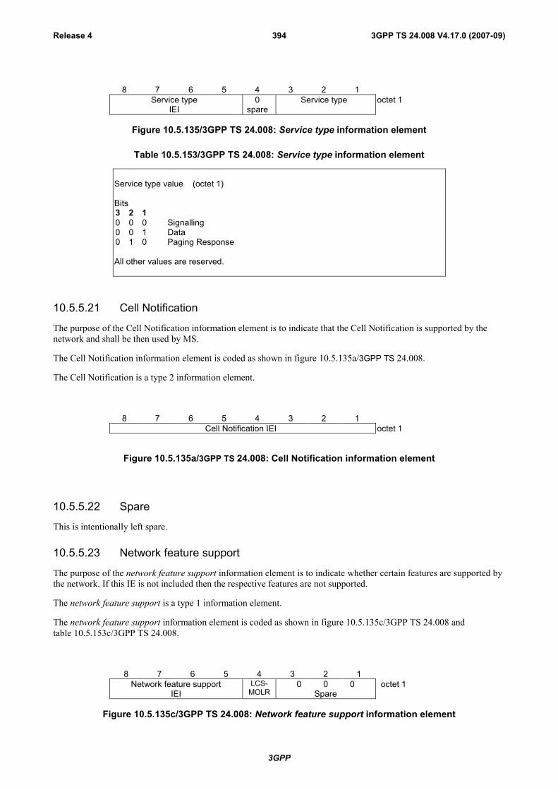
3GPP
3GPP TS 24.008 V4.17.0 (2007-09)Release 4 394
8 7 6 5 4 3 2 1Service type
IEI0
spareService type octet 1
Figure 10.5.135/3GPP TS 24.008: Service type information element
Table 10.5.153/3GPP TS 24.008: Service type information element
Service type value (octet 1)
Bits3 2 10 0 0 Signalling0 0 1 Data0 1 0 Paging Response
All other values are reserved.
10.5.5.21 Cell Notification
The purpose of the Cell Notification information element is to indicate that the Cell Notification is supported by thenetwork and shall be then used by MS.
The Cell Notification information element is coded as shown in figure 10.5.135a/3GPP TS 24.008.
The Cell Notification is a type 2 information element.
8 7 6 5 4 3 2 1Cell Notification IEI octet 1
Figure 10.5.135a/3GPP TS 24.008: Cell Notification information element
10.5.5.22 Spare
This is intentionally left spare.
10.5.5.23 Network feature support
The purpose of the network feature support information element is to indicate whether certain features are supported bythe network. If this IE is not included then the respective features are not supported.
The network feature support is a type 1 information element.
The network feature support information element is coded as shown in figure 10.5.135c/3GPP TS 24.008 andtable 10.5.153c/3GPP TS 24.008.
8 7 6 5 4 3 2 1Network feature support
IEILCS-
MOLR0 0 0
Spareoctet 1
Figure 10.5.135c/3GPP TS 24.008: Network feature support information element
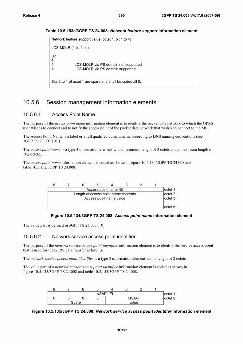
3GPP
3GPP TS 24.008 V4.17.0 (2007-09)Release 4 395
Table 10.5.153c/3GPP TS 24.008: Network feature support information element
Network feature support value (octet 1, bit 1 to 4)
LCS-MOLR (1 bit field)
Bit40 LCS-MOLR via PS domain not supported1 LCS-MOLR via PS domain supported
Bits 3 to 1 of octet 1 are spare and shall be coded all 0.
10.5.6 Session management information elements
10.5.6.1 Access Point Name
The purpose of the access point name information element is to identify the packet data network to which the GPRSuser wishes to connect and to notify the access point of the packet data network that wishes to connect to the MS.
The Access Point Name is a label or a full qualified domain name according to DNS naming conventions (see3GPP TS 23.003 [10]).
The access point name is a type 4 information element with a minimum length of 3 octets and a maximum length of102 octets.
The access point name information element is coded as shown in figure 10.5.134/3GPP TS 24.008 andtable 10.5.152/3GPP TS 24.008.
8 7 6 5 4 3 2 1Access point name IEI octet 1
Length of access point name contents octet 2Access point name value octet 3
octet n*
Figure 10.5.134/3GPP TS 24.008: Access point name information element
The value part is defined in 3GPP TS 23.003 [10].
10.5.6.2 Network service access point identifier
The purpose of the network service access point identifier information element is to identify the service access pointthat is used for the GPRS data transfer at layer 3.
The network service access point identifier is a type 3 information element with a length of 2 octets.
The value part of a network service access point identifier information element is coded as shown infigure 10.5.135/3GPP TS 24.008 and table 10.5.153/3GPP TS 24.008.
8 7 6 5 4 3 2 1NSAPI IEI octet 1
0 0 0 0 NSAPI octet 2Spare value
Figure 10.5.135/3GPP TS 24.008: Network service access point identifier information element
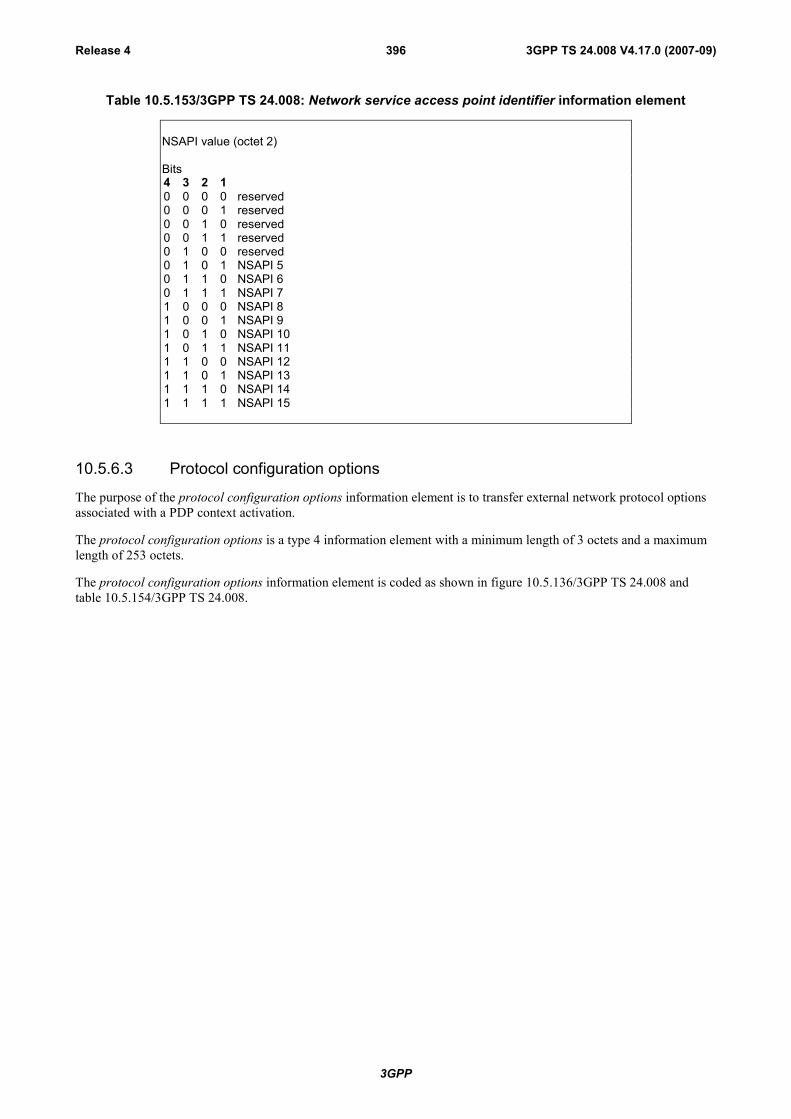
3GPP
3GPP TS 24.008 V4.17.0 (2007-09)Release 4 396
Table 10.5.153/3GPP TS 24.008: Network service access point identifier information element
NSAPI value (octet 2)
Bits4 3 2 10 0 0 0 reserved0 0 0 1 reserved0 0 1 0 reserved0 0 1 1 reserved0 1 0 0 reserved0 1 0 1 NSAPI 50 1 1 0 NSAPI 60 1 1 1 NSAPI 71 0 0 0 NSAPI 81 0 0 1 NSAPI 91 0 1 0 NSAPI 101 0 1 1 NSAPI 111 1 0 0 NSAPI 121 1 0 1 NSAPI 131 1 1 0 NSAPI 141 1 1 1 NSAPI 15
10.5.6.3 Protocol configuration options
The purpose of the protocol configuration options information element is to transfer external network protocol optionsassociated with a PDP context activation.
The protocol configuration options is a type 4 information element with a minimum length of 3 octets and a maximumlength of 253 octets.
The protocol configuration options information element is coded as shown in figure 10.5.136/3GPP TS 24.008 andtable 10.5.154/3GPP TS 24.008.
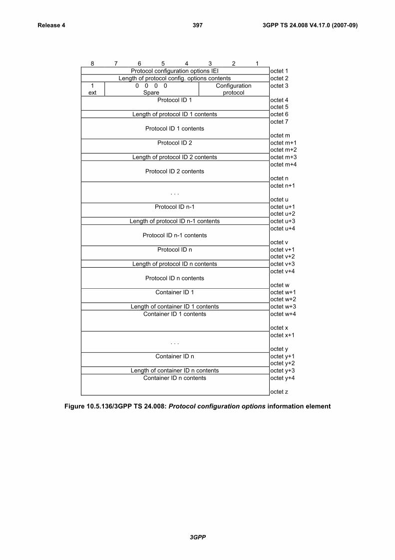
3GPP
3GPP TS 24.008 V4.17.0 (2007-09)Release 4 397
8 7 6 5 4 3 2 1Protocol configuration options IEI octet 1
Length of protocol config. options contents octet 21
ext0 0 0 0
SpareConfiguration
protocoloctet 3
Protocol ID 1 octet 4octet 5
Length of protocol ID 1 contents octet 6
Protocol ID 1 contentsoctet 7
octet mProtocol ID 2 octet m+1
octet m+2Length of protocol ID 2 contents octet m+3
Protocol ID 2 contentsoctet m+4
octet n
. . .octet n+1
octet uProtocol ID n-1 octet u+1
octet u+2Length of protocol ID n-1 contents octet u+3
Protocol ID n-1 contentsoctet u+4
octet vProtocol ID n octet v+1
octet v+2Length of protocol ID n contents octet v+3
Protocol ID n contentsoctet v+4
octet wContainer ID 1 octet w+1
octet w+2Length of container ID 1 contents octet w+3
Container ID 1 contents octet w+4
octet x
. . .octet x+1
octet yContainer ID n octet y+1
octet y+2Length of container ID n contents octet y+3
Container ID n contents octet y+4
octet z
Figure 10.5.136/3GPP TS 24.008: Protocol configuration options information element
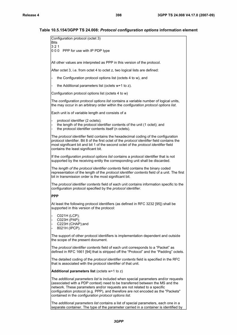
3GPP
3GPP TS 24.008 V4.17.0 (2007-09)Release 4 398
Table 10.5.154/3GPP TS 24.008: Protocol configuration options information element
Configuration protocol (octet 3)Bits3 2 10 0 0 PPP for use with IP PDP type
All other values are interpreted as PPP in this version of the protocol.
After octet 3, i.e. from octet 4 to octet z, two logical lists are defined:
- the Configuration protocol options list (octets 4 to w), and
- the Additional parameters list (octets w+1 to z).
Configuration protocol options list (octets 4 to w)
The configuration protocol options list contains a variable number of logical units,the may occur in an arbitrary order within the configuration protocol options list.
Each unit is of variable length and consists of a
- protocol identifier (2 octets);- the length of the protocol identifier contents of the unit (1 octet); and- the protocol identifier contents itself (n octets).
The protocol identifier field contains the hexadecimal coding of the configurationprotocol identifier. Bit 8 of the first octet of the protocol identifier field contains themost significant bit and bit 1 of the second octet of the protocol identifier fieldcontains the least significant bit.
If the configuration protocol options list contains a protocol identifier that is notsupported by the receiving entity the corresponding unit shall be discarded.
The length of the protocol identifier contents field contains the binary codedrepresentation of the length of the protocol identifier contents field of a unit. The firstbit in transmission order is the most significant bit.
The protocol identifier contents field of each unit contains information specific to theconfiguration protocol specified by the protocol identifier.
PPP
At least the following protocol identifiers (as defined in RFC 3232 [95]) shall besupported in this version of the protocol:
- C021H (LCP);- C023H (PAP);- C223H (CHAP);and- 8021H (IPCP).
The support of other protocol identifiers is implementation dependent and outsidethe scope of the present document.
The protocol identifier contents field of each unit corresponds to a “Packet” asdefined in RFC 1661 [94] that is stripped off the “Protocol” and the “Padding” octets.
The detailed coding of the protocol identifier contents field is specified in the RFCthat is associated with the protocol identifier of that unit.
Additional parameters list (octets w+1 to z)
The additional parameters list is included when special parameters and/or requests(associated with a PDP context) need to be transferred between the MS and thenetwork. These parameters and/or requests are not related to a specificconfiguration protocol (e.g. PPP), and therefore are not encoded as the "Packets"contained in the configuration protocol options list.
The additional parameters list contains a list of special parameters, each one in aseparate container. The type of the parameter carried in a container is identified by

3GPP
3GPP TS 24.008 V4.17.0 (2007-09)Release 4 399
a specific container identifier. In this version of the protocol, the following containeridentifiers are specified:
MS to network direction:
- 0003H (DNS Server Address Request).
Network to MS direction:
- 0003H (DNS Server Address).
If the additional parameters list contains a container identifier that is not supportedby the receiving entity the corresponding unit shall be discarded.
The container identifier field is encoded as the protocol identifier field and the lengthof container identifier contents field is encoded as the length of the protocol identifiercontents field.
When the container identifier indicates DNS Server Address Request, the containeridentifier contents field is empty and the length of container identifier contentsindicates a length equal to zero. If the container identifier contents field is not empty,it shall be ignored.
When the container identifier indicates DNS Server Address, the container identifiercontents field contains one IPv6 DNS server address (see 3GPP TS 27.060 [36a]).This IPv6 address is encoded as a 128-bit address according to RFC 2373 [93].When there is need to include more than one DNS server address, then morelogical units with container identifier indicating DNS Server Address are used.
NOTE 1: The additional parameters list and the configuration protocol options listare logically separated since they carry different type of information. The beginningof the additional parameters list is marked by a logical unit, which has an identifier(i.e. the first two octets) equal to a container identifier (i.e. it is not a protocolidentifier).
10.5.6.4 Packet data protocol address
The purpose of the packet data protocol address information element is to identify an address associated with a PDP.
The packet data protocol address is a type 4 information element with minimum length of 4 octets and a maximumlength of 20 octets.
The packet data protocol address information element is coded as shown in figure 10.5.137/3GPP TS 24.008 andtable 10.5.155/3GPP TS 24.008.
8 7 6 5 4 3 2 1Packet data protocol address IEI octet 1Length of PDP address contents octet 2
0 0 0 0spare
PDP type organisation octet 3
PDP type number octet 4
Address informationoctet 5
octet n
Figure 10.5.137/3GPP TS 24.008: Packet data protocol address information element
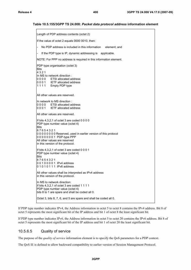
3GPP
3GPP TS 24.008 V4.17.0 (2007-09)Release 4 400
Table 10.5.155/3GPP TS 24.008: Packet data protocol address information element
Length of PDP address contents (octet 2)
If the value of octet 2 equals 0000 0010, then:
- No PDP address is included in this information element; and
- If the PDP type is IP, dynamic addressing is applicable.
NOTE: For PPP no address is required in this information element.
PDP type organisation (octet 3)Bits4 3 2 1In MS to network direction :0 0 0 0 ETSI allocated address0 0 0 1 IETF allocated address1 1 1 1 Empty PDP type
All other values are reserved.
In network to MS direction :0 0 0 0 ETSI allocated address0 0 0 1 IETF allocated address
All other values are reserved.
If bits 4,3,2,1 of octet 3 are coded 0 0 0 0PDP type number value (octet 4)Bits8 7 6 5 4 3 2 10 0 0 0 0 0 0 0 Reserved, used in earlier version of this protocol0 0 0 0 0 0 0 1 PDP-type PPPAll other values are reservedin this version of the protocol.
If bits 4,3,2,1 of octet 3 are coded 0 0 0 1PDP type number value (octet 4)Bits8 7 6 5 4 3 2 10 0 1 0 0 0 0 1 IPv4 address0 1 0 1 0 1 1 1 IPv6 address
All other values shall be interpreted as IPv4 addressin this version of the protocol.
In MS to network direction:If bits 4,3,2,1 of octet 3 are coded 1 1 1 1PDP type number value (octet 4)bits 8 to 1 are spare and shall be coded all 0.
Octet 3, bits 8, 7, 6, and 5 are spare and shall be coded all 0.
If PDP type number indicates IPv4, the Address information in octet 5 to octet 8 contains the IPv4 address. Bit 8 ofoctet 5 represents the most significant bit of the IP address and bit 1 of octet 8 the least significant bit.
If PDP type number indicates IPv6, the Address information in octet 5 to octet 20 contains the IPv6 address. Bit 8 ofoctet 5 represents the most significant bit of the IP address and bit 1 of octet 20 the least significant bit.
10.5.6.5 Quality of service
The purpose of the quality of service information element is to specify the QoS parameters for a PDP context.
The QoS IE is defined to allow backward compatibility to earlier version of Session Management Protocol.

3GPP
3GPP TS 24.008 V4.17.0 (2007-09)Release 4 401
The quality of service is a type 4 information element with a length of 13 octets. The QoS requested by the MS shall beencoded both in the QoS attributes specified in octets 3-5 and in the QoS attributes specified in octets 6-13.
A QoS IE received without octets 6-13 shall be accepted by a receiving entity.
NOTE: This behavior is required for interworking with entities supporting an earlier version of the protocol.
The quality of service information element is coded as shown in figure 10.5.138/3GPP TS 24.008 andtable 10.5.156/3GPP TS 24.008.
8 7 6 5 4 3 2 1Quality of service IEI octet 1
Length of quality of service IE Octet 20 0spare
Delayclass
Reliabilityclass
octet 3
Peakthroughput
0spare
Precedenceclass
octet 4
0 0 0spare
Meanthroughput
octet 5
Traffic Class Delivery order Delivery of erroneousSDU
Octet 6
Maximum SDU size Octet 7Maximum bit rate for uplink Octet 8
Maximum bit rate for downlink Octet 9Residual BER SDU error ratio Octet 10
Transfer delay Traffic Handlingpriority
Octet 11
Guaranteed bit rate for uplinkOctet 12
Guaranteed bit rate for downlink Octet 13
Figure 10.5.138/3GPP TS 24.008: Quality of service information element
Table 10.5.156/3GPP TS 24.008: Quality of service information element
Reliability class, octet 3 (see 3GPP TS 23.107)Bits3 2 1In MS to network direction:0 0 0 Subscribed reliability classIn network to MS direction:0 0 0 ReservedIn MS to network direction and in network to MS direction:0 0 1 Acknowledged GTP, LLC, and RLC; Protected data0 1 0 Unacknowledged GTP; Acknowledged LLC and RLC, Protected data0 1 1 Unacknowledged GTP and LLC; Acknowledged RLC, Protected data1 0 0 Unacknowledged GTP, LLC, and RLC, Protected data1 0 1 Unacknowledged GTP, LLC, and RLC, Unprotected data1 1 1 Reserved
All other values are interpreted as Unacknowledged GTP and LLC; Acknowledged RLC, Protected data in this version ofthe protocol.
Delay class, octet 3 (see 3GPP TS 22.060 and 3GPP TS 23.107)Bits6 5 4In MS to network direction:0 0 0 Subscribed delay classIn network to MS direction:0 0 0 ReservedIn MS to network direction and in network to MS direction:0 0 1 Delay class 10 1 0 Delay class 20 1 1 Delay class 3
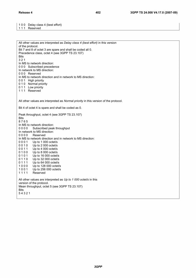
3GPP
3GPP TS 24.008 V4.17.0 (2007-09)Release 4 402
1 0 0 Delay class 4 (best effort)1 1 1 Reserved
All other values are interpreted as Delay class 4 (best effort) in this versionof the protocol.Bit 7 and 8 of octet 3 are spare and shall be coded all 0.Precedence class, octet 4 (see 3GPP TS 23.107)Bits3 2 1In MS to network direction:0 0 0 Subscribed precedenceIn network to MS direction:0 0 0 ReservedIn MS to network direction and in network to MS direction:0 0 1 High priority0 1 0 Normal priority0 1 1 Low priority1 1 1 Reserved
All other values are interpreted as Normal priority in this version of the protocol.
Bit 4 of octet 4 is spare and shall be coded as 0.
Peak throughput, octet 4 (see 3GPP TS 23.107)Bits8 7 6 5In MS to network direction:0 0 0 0 Subscribed peak throughputIn network to MS direction:0 0 0 0 ReservedIn MS to network direction and in network to MS direction:0 0 0 1 Up to 1 000 octet/s0 0 1 0 Up to 2 000 octet/s0 0 1 1 Up to 4 000 octet/s0 1 0 0 Up to 8 000 octet/s0 1 0 1 Up to 16 000 octet/s0 1 1 0 Up to 32 000 octet/s0 1 1 1 Up to 64 000 octet/s1 0 0 0 Up to 128 000 octet/s1 0 0 1 Up to 256 000 octet/s1 1 1 1 Reserved
All other values are interpreted as Up to 1 000 octet/s in thisversion of the protocol.Mean throughput, octet 5 (see 3GPP TS 23.107)Bits5 4 3 2 1

3GPP
3GPP TS 24.008 V4.17.0 (2007-09)Release 4 403
In MS to network direction:0 0 0 0 0 Subscribed mean throughputIn network to MS direction:0 0 0 0 0 ReservedIn MS to network direction and in network to MS direction:0 0 0 0 1 100 octet/h0 0 0 1 0 200 octet/h0 0 0 1 1 500 octet/h0 0 1 0 0 1 000 octet/h0 0 1 0 1 2 000 octet/h0 0 1 1 0 5 000 octet/h0 0 1 1 1 10 000 octet/h0 1 0 0 0 20 000 octet/h0 1 0 0 1 50 000 octet/h0 1 0 1 0 100 000 octet/h0 1 0 1 1 200 000 octet/h0 1 1 0 0 500 000 octet/h0 1 1 0 1 1 000 000 octet/h0 1 1 1 0 2 000 000 octet/h0 1 1 1 1 5 000 000 octet/h1 0 0 0 0 10 000 000 octet/h1 0 0 0 1 20 000 000 octet/h1 0 0 1 0 50 000 000 octet/h1 1 1 1 0 Reserved1 1 1 1 1 Best effortThe value Best effort indicates that throughput shall be made available to the MS on a per need and availability basis.All other values are interpreted as Best effort in thisversion of the protocol.
Bits 8 to 6 of octet 5 are spare and shall be coded all 0.
Delivery of erroneous SDUs, octet 6 (see 3GPP TS 23.107)Bits3 2 1In MS to network direction:0 0 0 Subscribed delivery of erroneous SDUsIn network to MS direction:0 0 0 ReservedIn MS to network direction and in network to MS direction:0 0 1 No detect ('-')0 1 0 Erroneous SDUs are delivered ('yes')0 1 1 Erroneous SDUs are not delivered ('no')1 1 1 Reserved
The network shall map all other values not explicitly defined onto one of the values defined in this version of the protocol.The network shall return a negotiated value which is explicitly defined in this version of this protocol.
The MS shall consider all other values as reserved.
Delivery order, octet 6 (see 3GPP TS 23.107)Bits5 4 3In MS to network direction:0 0 Subscribed delivery orderIn network to MS direction:0 0 ReservedIn MS to network direction and in network to MS direction:0 1 With delivery order ('yes')1 0 Without delivery order ('no')1 1 Reserved

3GPP
3GPP TS 24.008 V4.17.0 (2007-09)Release 4 404
Traffic class, octet 6 (see 3GPP TS 23.107)Bits8 7 6In MS to network direction:0 0 0 Subscribed traffic classIn network to MS direction:0 0 0 ReservedIn MS to network direction and in network to MS direction:0 0 1 Conversational class0 1 0 Streaming class0 1 1 Interactive class1 0 0 Background class1 1 1 Reserved
The network shall map all other values not explicitly defined onto one of the values defined in this version of the protocol.The network shall return a negotiated value which is explicitly defined in this version of this protocol.
The MS shall consider all other values as reserved.
Maximum SDU size, octet 7 (see 3GPP TS 23.107)In MS to network direction:0 0 0 0 0 0 0 0 Subscribed maximum SDU size1 1 1 1 1 1 1 1 ReservedIn network to MS direction:0 0 0 0 0 0 0 0 Reserved1 1 1 1 1 1 1 1 ReservedIn MS to network direction and in network to MS direction:
For values in the range 00000001 to 10010110 the Maximum SDU size value is binary coded in 8 bits, using agranularity of 10 octets, giving a range of values from 10 octets to 1500 octets.Values above 10010110 are as below:1 0 0 1 0 1 1 1 1502 octets1 0 0 1 1 0 0 0 1510 octets1 0 0 1 1 0 0 1 1520 octets
The network shall map all other values not explicitly defined onto one of the values defined in this version of the protocol.The network shall return a negotiated value which is explicitly defined in this version of this protocol.
The MS shall consider all other values as reserved.
Maximum bit rate for uplink, octet 8Bits8 7 6 5 4 3 2 1In MS to network direction:0 0 0 0 0 0 0 0 Subscribed maximum bit rate for uplinkIn network to MS direction:0 0 0 0 0 0 0 0 ReservedIn MS to network direction and in network to MS direction:0 0 0 0 0 0 0 1 The maximum bit rate is binary coded in 8 bits, using a granularity of 1 kbps0 0 1 1 1 1 1 1 giving a range of values from 1 kbps to 63 kbps in 1 kbps increments.
0 1 0 0 0 0 0 0 The maximum bit rate is 64 kbps + ((the binary coded value in 8 bits –01000000) * 8 kbps)0 1 1 1 1 1 1 1 giving a range of values from 64 kbps to 568 kbps in 8 kbps increments.
1 0 0 0 0 0 0 0 The maximum bit rate is 576 kbps + ((the binary coded value in 8 bits –10000000) * 64 kbps)1 1 1 1 1 1 1 0 giving a range of values from 576 kbps to 8640 kbps in 64 kbps increments.
1 1 1 1 1 1 1 1 0kbps
Maximum bit rate for downlink, octet 9 (see 3GPP TS 23.107)
Coding is identical to that of Maximum bit rate for uplink.
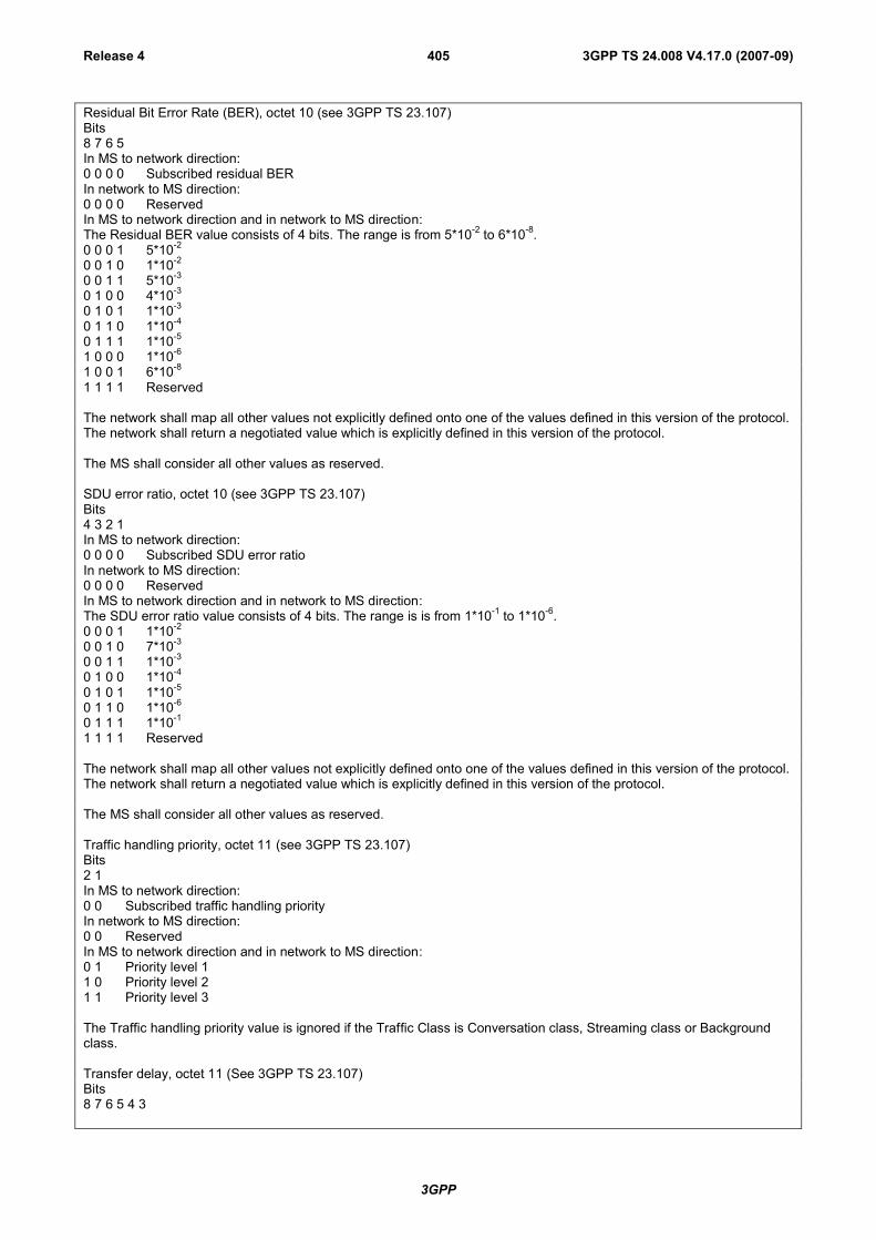
3GPP
3GPP TS 24.008 V4.17.0 (2007-09)Release 4 405
Residual Bit Error Rate (BER), octet 10 (see 3GPP TS 23.107)Bits8 7 6 5In MS to network direction:0 0 0 0 Subscribed residual BERIn network to MS direction:0 0 0 0 ReservedIn MS to network direction and in network to MS direction:The Residual BER value consists of 4 bits. The range is from 5*10-2 to 6*10-8.0 0 0 1 5*10-2
0 0 1 0 1*10-2
0 0 1 1 5*10-3
0 1 0 0 4*10-3
0 1 0 1 1*10-3
0 1 1 0 1*10-4
0 1 1 1 1*10-5
1 0 0 0 1*10-6
1 0 0 1 6*10-8
1 1 1 1 Reserved
The network shall map all other values not explicitly defined onto one of the values defined in this version of the protocol.The network shall return a negotiated value which is explicitly defined in this version of the protocol.
The MS shall consider all other values as reserved.
SDU error ratio, octet 10 (see 3GPP TS 23.107)Bits4 3 2 1In MS to network direction:0 0 0 0 Subscribed SDU error ratioIn network to MS direction:0 0 0 0 ReservedIn MS to network direction and in network to MS direction:The SDU error ratio value consists of 4 bits. The range is is from 1*10-1 to 1*10-6.0 0 0 1 1*10-2
0 0 1 0 7*10-3
0 0 1 1 1*10-3
0 1 0 0 1*10-4
0 1 0 1 1*10-5
0 1 1 0 1*10-6
0 1 1 1 1*10-1
1 1 1 1 Reserved
The network shall map all other values not explicitly defined onto one of the values defined in this version of the protocol.The network shall return a negotiated value which is explicitly defined in this version of the protocol.
The MS shall consider all other values as reserved.
Traffic handling priority, octet 11 (see 3GPP TS 23.107)Bits2 1In MS to network direction:0 0 Subscribed traffic handling priorityIn network to MS direction:0 0 ReservedIn MS to network direction and in network to MS direction:0 1 Priority level 11 0 Priority level 21 1 Priority level 3
The Traffic handling priority value is ignored if the Traffic Class is Conversation class, Streaming class or Backgroundclass.
Transfer delay, octet 11 (See 3GPP TS 23.107)Bits8 7 6 5 4 3

3GPP
3GPP TS 24.008 V4.17.0 (2007-09)Release 4 406
In MS to network direction:0 0 0 0 0 0 Subscribed transfer delayIn network to MS direction:0 0 0 0 0 0 ReservedIn MS to network direction and in network to MS direction:
0 0 0 0 0 1 The Transfer delay is binary coded in 6 bits, using a granularity of 10 ms0 0 1 1 1 1 giving a range of values from 10 ms to 150 ms in 10 ms increments
0 1 0 0 0 0 The transfer delay is 200 ms + ((the binary coded value in 6 bits – 010000) * 50 ms)0 1 1 1 1 1 giving a range of values from 200 ms to 950 ms in 50ms increments
1 0 0 0 0 0 The transfer delay is 1000 ms + ((the binary coded value in 6 bits – 100000) * 100 ms)1 1 1 1 1 0 giving a range of values from 1000 ms to 4000 ms in 100ms increments
1 1 1 1 1 1 Reserved
The Transfer delay value is ignored if the Traffic Class is Interactive class or Background class.Guaranteed bit rate for uplink, octet 12 (See 3GPP TS 23.107)
Coding is identical to that of Maximum bit rate for uplink.
The Guaranteed bit rate for uplink value is ignored if the Traffic Class is Interactive class or Background class, orMaximum bit rate for uplink is set to 0 kbps.Guaranteed bit rate for downlink, octet 13(See 3GPP TS 23.107)
Coding is identical to that of Maximum bit rate for uplink.
The Guaranteed bit rate for downlink value is ignored if the Traffic Class is Interactive class or Background class, orMaximum bit rate for downlink is set to 0 kbps.
10.5.6.6 SM cause
The purpose of the SM cause information element is to indicate the reason why a session management request isrejected.
The SM cause is a type 3 information element with 2 octets length.
The SM cause information element is coded as shown in figure 10.5.139/3GPP TS 24.008 and table 10.5.157/3GPP TS24.008.
8 7 6 5 4 3 2 1SM cause IEI octet 1Cause value octet 2
Figure 10.5.139/3GPP TS 24.008: SM cause information element
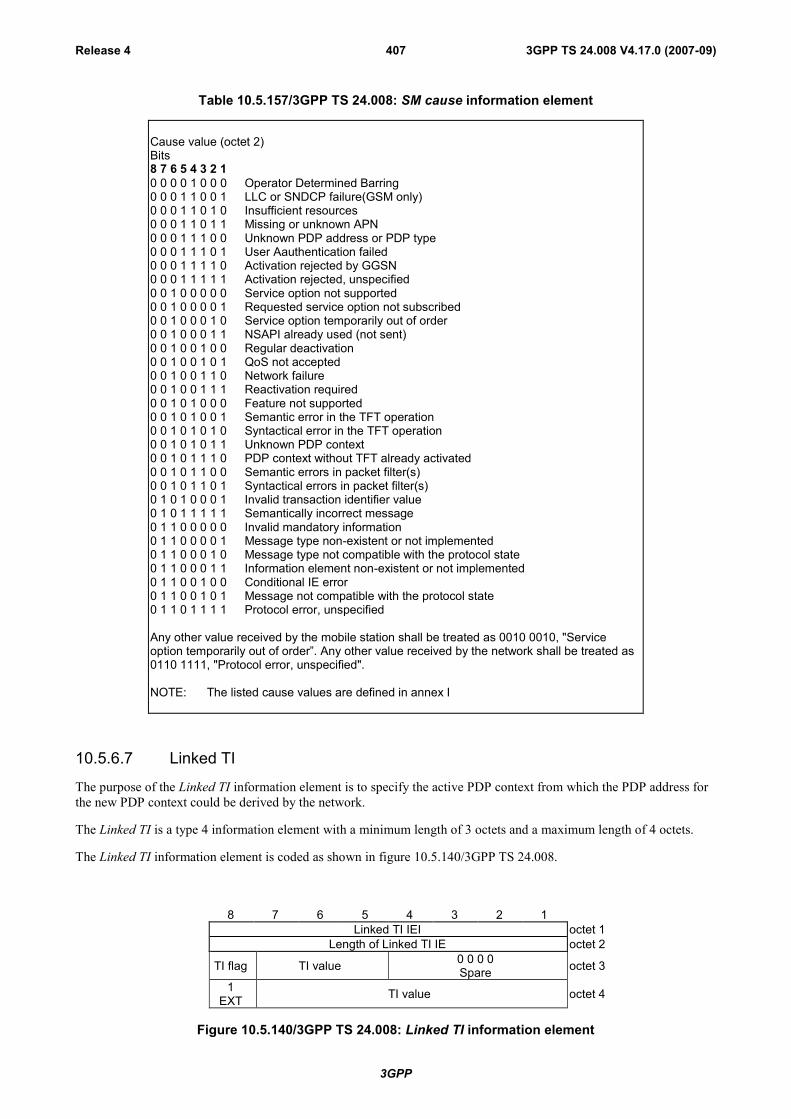
3GPP
3GPP TS 24.008 V4.17.0 (2007-09)Release 4 407
Table 10.5.157/3GPP TS 24.008: SM cause information element
Cause value (octet 2)Bits8 7 6 5 4 3 2 10 0 0 0 1 0 0 0 Operator Determined Barring0 0 0 1 1 0 0 1 LLC or SNDCP failure(GSM only)0 0 0 1 1 0 1 0 Insufficient resources0 0 0 1 1 0 1 1 Missing or unknown APN0 0 0 1 1 1 0 0 Unknown PDP address or PDP type0 0 0 1 1 1 0 1 User Aauthentication failed0 0 0 1 1 1 1 0 Activation rejected by GGSN0 0 0 1 1 1 1 1 Activation rejected, unspecified0 0 1 0 0 0 0 0 Service option not supported0 0 1 0 0 0 0 1 Requested service option not subscribed0 0 1 0 0 0 1 0 Service option temporarily out of order0 0 1 0 0 0 1 1 NSAPI already used (not sent)0 0 1 0 0 1 0 0 Regular deactivation0 0 1 0 0 1 0 1 QoS not accepted0 0 1 0 0 1 1 0 Network failure0 0 1 0 0 1 1 1 Reactivation required0 0 1 0 1 0 0 0 Feature not supported0 0 1 0 1 0 0 1 Semantic error in the TFT operation0 0 1 0 1 0 1 0 Syntactical error in the TFT operation0 0 1 0 1 0 1 1 Unknown PDP context0 0 1 0 1 1 1 0 PDP context without TFT already activated0 0 1 0 1 1 0 0 Semantic errors in packet filter(s)0 0 1 0 1 1 0 1 Syntactical errors in packet filter(s)0 1 0 1 0 0 0 1 Invalid transaction identifier value0 1 0 1 1 1 1 1 Semantically incorrect message0 1 1 0 0 0 0 0 Invalid mandatory information0 1 1 0 0 0 0 1 Message type non-existent or not implemented0 1 1 0 0 0 1 0 Message type not compatible with the protocol state0 1 1 0 0 0 1 1 Information element non-existent or not implemented0 1 1 0 0 1 0 0 Conditional IE error0 1 1 0 0 1 0 1 Message not compatible with the protocol state0 1 1 0 1 1 1 1 Protocol error, unspecified
Any other value received by the mobile station shall be treated as 0010 0010, "Serviceoption temporarily out of order”. Any other value received by the network shall be treated as0110 1111, "Protocol error, unspecified".
NOTE: The listed cause values are defined in annex I
10.5.6.7 Linked TI
The purpose of the Linked TI information element is to specify the active PDP context from which the PDP address forthe new PDP context could be derived by the network.
The Linked TI is a type 4 information element with a minimum length of 3 octets and a maximum length of 4 octets.
The Linked TI information element is coded as shown in figure 10.5.140/3GPP TS 24.008.
8 7 6 5 4 3 2 1Linked TI IEI octet 1
Length of Linked TI IE octet 2
TI flag TI value 0 0 0 0Spare octet 3
1EXT TI value octet 4
Figure 10.5.140/3GPP TS 24.008: Linked TI information element
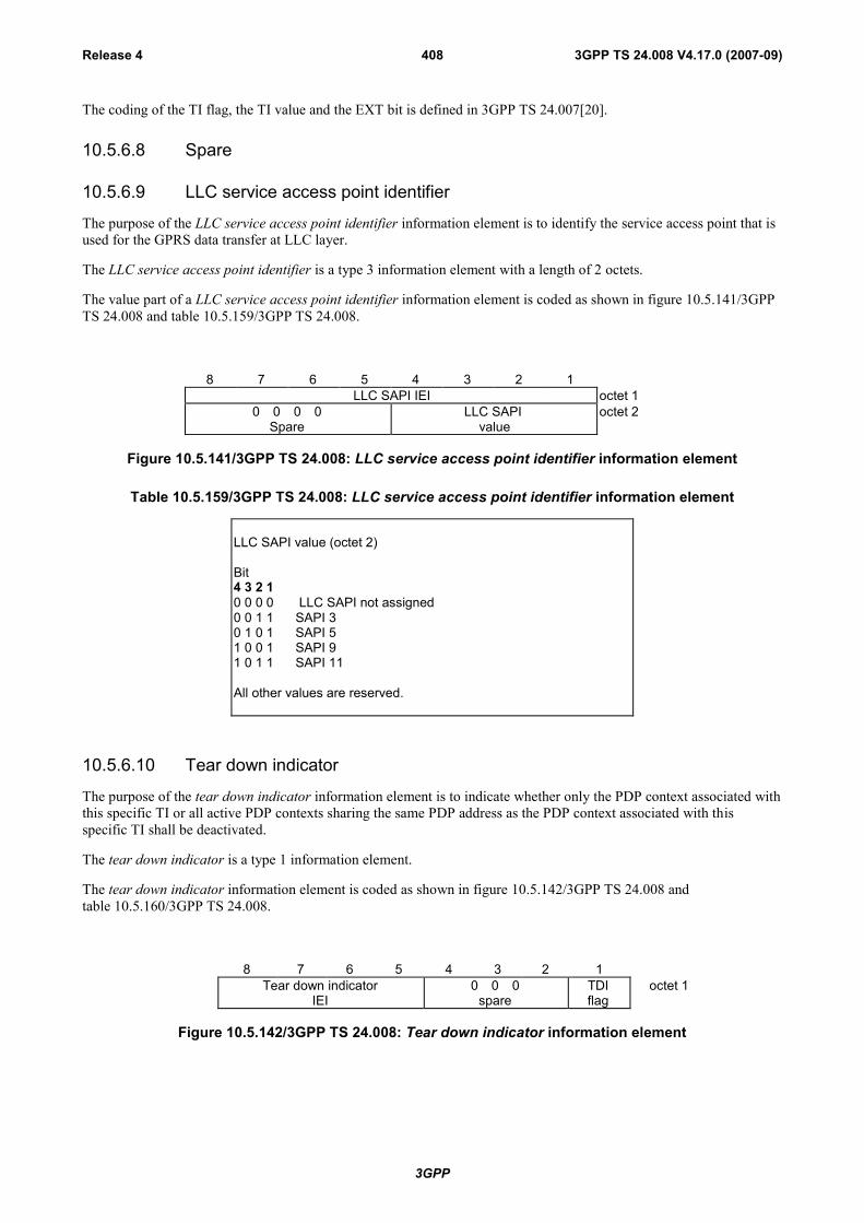
3GPP
3GPP TS 24.008 V4.17.0 (2007-09)Release 4 408
The coding of the TI flag, the TI value and the EXT bit is defined in 3GPP TS 24.007[20].
10.5.6.8 Spare
10.5.6.9 LLC service access point identifier
The purpose of the LLC service access point identifier information element is to identify the service access point that isused for the GPRS data transfer at LLC layer.
The LLC service access point identifier is a type 3 information element with a length of 2 octets.
The value part of a LLC service access point identifier information element is coded as shown in figure 10.5.141/3GPPTS 24.008 and table 10.5.159/3GPP TS 24.008.
8 7 6 5 4 3 2 1 LLC SAPI IEI octet 1
0 0 0 0Spare
LLC SAPI value
octet 2
Figure 10.5.141/3GPP TS 24.008: LLC service access point identifier information element
Table 10.5.159/3GPP TS 24.008: LLC service access point identifier information element
LLC SAPI value (octet 2)
Bit4 3 2 10 0 0 0 LLC SAPI not assigned0 0 1 1 SAPI 30 1 0 1 SAPI 51 0 0 1 SAPI 91 0 1 1 SAPI 11
All other values are reserved.
10.5.6.10 Tear down indicator
The purpose of the tear down indicator information element is to indicate whether only the PDP context associated withthis specific TI or all active PDP contexts sharing the same PDP address as the PDP context associated with thisspecific TI shall be deactivated.
The tear down indicator is a type 1 information element.
The tear down indicator information element is coded as shown in figure 10.5.142/3GPP TS 24.008 andtable 10.5.160/3GPP TS 24.008.
8 7 6 5 4 3 2 1Tear down indicator
IEI0 0 0
spareTDIflag
octet 1
Figure 10.5.142/3GPP TS 24.008: Tear down indicator information element

3GPP
3GPP TS 24.008 V4.17.0 (2007-09)Release 4 409
Table 10.5.160/3GPP TS 24.008: Tear down indicator information element
Tear down indicator(TDI) flag (octet 1)
Bit10 tear down not requested1 tear down requested
10.5.6.11 Packet Flow Identifier
The Packet Flow Identifier (PFI) information element indicates the Packet Flow Identifier for a Packet Flow Context.
The Packet Flow Identifier is a a type 4 information element with 3 octets length.
The Packet Flow Identifier information element is coded as shown in figure 10.5.143/3GPP TS 24.008 andtable 10.5.161/3GPP TS 24.008.
8 7 6 5 4 3 2 1Packet Flow Identifier IEI octet 1
Length of Packet Flow Identifier IE octet 2Spare
0Packet Flow Identifier value octet 3
Figure 10.5.143/3GPP TS 24.008: Packet Flow Identifier information element
Table 10.5.161/3GPP TS 24.008: Packet Flow Identifier information element
Packet Flow Identifier value (octet 3)Bits7 6 5 4 3 2 10 0 0 0 0 0 0 Best Effort0 0 0 0 0 0 1 Signaling0 0 0 0 0 1 0 SMS
0 0 0 0 0 1 1 }to } reserved
0 0 0 0 1 1 1 }
0 0 0 1 0 0 0 }to } dynamically assigned
1 1 1 1 1 1 1 }
10.5.6.12 Traffic Flow Template
The purpose of the traffic flow template information element is to specify the TFT parameters and operations for a PDPcontext.
The traffic flow template is a type 4 information element with a minimum length of 3 octets. The maximum length forthe IE is 257 octets.
NOTE 1: The IE length restriction is due to the maximum length that can be encoded in a single length octet.

3GPP
3GPP TS 24.008 V4.17.0 (2007-09)Release 4 410
NOTE 2: A maximum size IPv4 packet filter can be 32 bytes. Therefore, 7 maximum size IPv4 type packet filters,plus the last packet filter which can contain max 30 octets can fit into one TFT, i.e. if needed not allpacket filter components can be defined into one message. A maximum size Ipv6 packet filter can be 60bytes. Therefore, only 4 maximum size IPv6 packet filters can fit into one TFT. However, using "Addpacket filters to existing TFT", it's possible to create a TFT including 8 maximum size Ipv4 or IPv6filters.
The traffic flow template information element is coded as shown in figure 10.5.144/3GPP TS 24.008 and table10.5.162/3GPP TS 24.008.
8 7 6 5 4 3 2 1Traffic flow template IEI Octet 1
Length of traffic flow template IE Octet 2TFT operation code Spare 0 Number of packet filters Octet 3
Packet filter listOctet 4
Octet z
Figure 10.5.144/3GPP TS 24.008: Traffic flow template information element
8 7 6 5 4 3 2 1Packet filter identifier 1 Octet 4Packet filter identifier 2 Octet 5
…Packet filter identifier N Octet N+3
Figure 10.5.144a/3GPP TS 24.008: Packet filter list when the TFT operation is "delete packet filtersfrom existing TFT" (z=N+3)
8 7 6 5 4 3 2 1Packet filter identifier 1 Octet 4
Packet filter evaluation precedence 1 Octet 5Length of Packet filter contents 1 Octet 6
Packet filter contents 1 Octet 7Octet m
Packet filter identifier 2 Octet m+1Packet filter evaluation precedence 2 Octet m+2
Length of Packet filter contents 2 Octet m+3Packet filter contents 2 Octet m+4
Octet n… Octet n+1
Octet yPacket filter identifier N Octet y+1
Packet filter evaluation precedence N Octet y+2Length of Packet filter contents N Octet y+3
Packet filter contents N Octet y+4Octet z
Figure 10.5.144b/3GPP TS 24.008: Packet filter list when the TFT operation is "create new TFT", or"add packet filters to existing TFT" or "replace packet filters in existing TFT"

3GPP
3GPP TS 24.008 V4.17.0 (2007-09)Release 4 411
Table 10.5.162/3GPP TS 24.008: Traffic flow template information element
TFT operation code (octet 3)Bits8 7 6
0 0 0 Spare0 0 1 Create new TFT
0 1 0 Delete existing TFT0 1 1 Add packet filters to existing TFT
1 0 0 Replace packet filters in existing TFT
1 0 1 Delete packet filters from existing TFT1 1 0 Reserved
1 1 1 Reserved
Number of packet filters (octet 3)
The number of packet filters contains the binary coding for the number of packetfilters in the packet filter list. The number of packet filters field is encoded in bits 4through 1 of octet 3 where bit 4 is the most significant and bit 1 is the leastsignificant bit. For the "delete existing TFT" operation, the number of packet filtersshall be coded as 0. For all other operations, the number of packet filters shall begreater than 0 and less than or equal to 8.
Packet filter list (octets 4 to z)
The packet filter list contains a variable number of packet filters. For the "deleteexisting TFT" operation, the packet filter list shall be empty.
For the "delete packet filters from existing TFT" operation, the packet filter list shallcontain a variable number of packet filter identifiers. This number shall be derivedfrom the coding of the number of packet filters field in octet 3.
For the "create new TFT", "add packet filters to existing TFT" and "replace packetfilters in existing TFT" operations, the packet filter list shall contain a variablenumber of packet filters. This number shall be derived from the coding of thenumber of packet filters field in octet 3.
Each packet filter is of variable length and consists of
- a packet filter identifier (1 octet);- a packet filter evaluation precedence (1 octet);- the length of the packet filter contents (1 octet); and- the packet filter contents itself (v octets).
The packet filter identifier field is used to identify each packet filter in a TFT. Sincethe maximum number of packet filters in a TFT is 8, only the least significant 3 bitsare used. Bits 8 through 4 are spare bits.
The packet filter evaluation precedence field is used to specify the precedence forthe packet filter among all packet filters in all TFTs associated with this PDPaddress. Higher the value of the packet filter evaluation precedence field, lower theprecedence of that packet filter is. The first bit in transmission order is the mostsignificant bit.
The length of the packet filter contents field contains the binary codedrepresentation of the length of the packet filter contents field of a packet filter. Thefirst bit in transmission order is the most significant bit.

3GPP
3GPP TS 24.008 V4.17.0 (2007-09)Release 4 412
Table 10.5.162/3GPP TS 24.008 (continued): Traffic flow template information element
The packet filter contents field is of variable size and contains a variable number (atleast one) of packet filter components. Each packet filter component shall beencoded as a sequence of a one octet packet filter component type identifier and afixed length packet filter component value field. The packet filter component typeidentifier shall be transmitted first.In each packet filter, there shall not be more than one occurrence of each packet filtercomponent type. Among the "IPv4 source address type" and "IPv6 source addresstype" packet filter components, only one shall be present in one packet filter. Amongthe "single destination port type" and "destination port range type" packet filtercomponents, only one shall be present in one packet filter. Among the "single sourceport type" and "source port range type" packet filter components, only one shall bepresent in one packet filter.Packet filter component type identifierBits8 7 6 5 4 3 2 10 0 0 1 0 0 0 0 IPv4 source address type0 0 1 0 0 0 0 0 IPv6 source address type0 0 1 1 0 0 0 0 Protocol identifier/Next header type0 1 0 0 0 0 0 0 Single destination port type0 1 0 0 0 0 0 1 Destination port range type0 1 0 1 0 0 0 0 Single source port type0 1 0 1 0 0 0 1 Source port range type0 1 1 0 0 0 0 0 Security parameter index type0 1 1 1 0 0 0 0 Type of service/Traffic class type1 0 0 0 0 0 0 0 Flow label typeAll other values are reserved.For "IPv4 source address type", the packet filter component value field shall beencoded as a sequence of a four octet IPv4 address field and a four octet IPv4address mask field. The IPv4 address field shall be transmitted first.For "IPv6 source address type", the packet filter component value field shall beencoded as a sequence of a sixteen octet IPv6 address field and a sixteen octet IPv6address mask field. The IPv6 address field shall be transmitted first.For "Protocol identifier/Next header type", the packet filter component value field shallbe encoded as one octet which specifies the IPv4 protocol identifier or IPv6 nextheader.For "Single destination port type" and "Single source port type", the packet filtercomponent value field shall be encoded as two octet which specifies a port number.For "Destination port range type" and "Source port range type", the packet filtercomponent value field shall be encoded as a sequence of a two octet port range lowlimit field and a two octet port range high limit field. The port range low limit field shallbe transmitted first.For "Security parameter index", the packet filter component value field shall beencoded as four octet which specifies the IPSec security parameter index.For "Type of service/Traffic class type", the packet filter component value field shallbe encoded as a sequence of a one octet Type-of-Service/Traffic Class field and aone octet Type-of-Service/Traffic Class mask field. The Type-of-Service/Traffic Classfield shall be transmitted first.For "Flow label type", the packet filter component value field shall be encoded asthree octet which specifies the IPv6 flow label. The bits 8 through 5 of the first octetshall be spare whereas the remaining 20 bits shall contain the IPv6 flow label.
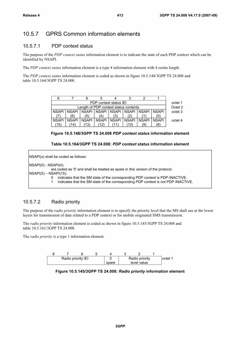
3GPP
3GPP TS 24.008 V4.17.0 (2007-09)Release 4 413
10.5.7 GPRS Common information elements
10.5.7.1 PDP context status
The purpose of the PDP context status information element is to indicate the state of each PDP context which can beidentified by NSAPI.
The PDP context status information element is a type 4 information element with 4 octets length.
The PDP context status information element is coded as shown in figure 10.5.148/3GPP TS 24.008 andtable 10.5.164/3GPP TS 24.008.
8 7 6 5 4 3 2 1PDP context status IEI octet 1
Length of PDP context status contents Octet 2NSAPI
(7)NSAPI
(6)NSAPI
(5)NSAPI
(4)NSAPI
(3)NSAPI
(2)NSAPI
(1)NSAPI
(0)octet 3
NSAPI(15)
NSAPI(14)
NSAPI(13)
NSAPI(12)
NSAPI(11)
NSAPI(10)
NSAPI(9)
NSAPI(8)
octet 4
Figure 10.5.148/3GPP TS 24.008 PDP context status information element
Table 10.5.164/3GPP TS 24.008: PDP context status information element
NSAPI(x) shall be coded as follows:
NSAPI(0) - NSAPI(4):are coded as '0' and shall be treated as spare in this version of the protocol.
NSAPI(5) – NSAPI(15):0 indicates that the SM state of the corresponding PDP context is PDP-INACTIVE.1 indicates that the SM state of the corresponding PDP context is not PDP-INACTIVE.
10.5.7.2 Radio priority
The purpose of the radio priority information element is to specify the priority level that the MS shall use at the lowerlayers for transmission of data related to a PDP context or for mobile originated SMS transmission.
The radio priority information element is coded as shown in figure 10.5.145/3GPP TS 24.008 andtable 10.5.161/3GPP TS 24.008.
The radio priority is a type 1 information element.
8 7 6 5 4 3 2 1Radio priority IEI 0
spareRadio priority
level valueoctet 1
Figure 10.5.145/3GPP TS 24.008: Radio priority information element
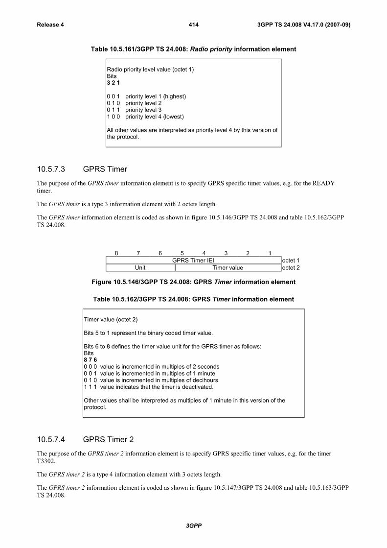
3GPP
3GPP TS 24.008 V4.17.0 (2007-09)Release 4 414
Table 10.5.161/3GPP TS 24.008: Radio priority information element
Radio priority level value (octet 1)Bits3 2 1
0 0 1 priority level 1 (highest)0 1 0 priority level 20 1 1 priority level 31 0 0 priority level 4 (lowest)
All other values are interpreted as priority level 4 by this version ofthe protocol.
10.5.7.3 GPRS Timer
The purpose of the GPRS timer information element is to specify GPRS specific timer values, e.g. for the READYtimer.
The GPRS timer is a type 3 information element with 2 octets length.
The GPRS timer information element is coded as shown in figure 10.5.146/3GPP TS 24.008 and table 10.5.162/3GPPTS 24.008.
8 7 6 5 4 3 2 1GPRS Timer IEI octet 1
Unit Timer value octet 2
Figure 10.5.146/3GPP TS 24.008: GPRS Timer information element
Table 10.5.162/3GPP TS 24.008: GPRS Timer information element
Timer value (octet 2)
Bits 5 to 1 represent the binary coded timer value.
Bits 6 to 8 defines the timer value unit for the GPRS timer as follows:Bits8 7 60 0 0 value is incremented in multiples of 2 seconds0 0 1 value is incremented in multiples of 1 minute0 1 0 value is incremented in multiples of decihours1 1 1 value indicates that the timer is deactivated.
Other values shall be interpreted as multiples of 1 minute in this version of theprotocol.
10.5.7.4 GPRS Timer 2
The purpose of the GPRS timer 2 information element is to specify GPRS specific timer values, e.g. for the timerT3302.
The GPRS timer 2 is a type 4 information element with 3 octets length.
The GPRS timer 2 information element is coded as shown in figure 10.5.147/3GPP TS 24.008 and table 10.5.163/3GPPTS 24.008.

3GPP
3GPP TS 24.008 V4.17.0 (2007-09)Release 4 415
8 7 6 5 4 3 2 1GPRS Timer 2 IEI octet 1
Length of GPRS Timer 2 contents octet 2GPRS Timer 2 value octet 3
Figure 10.5.147/3GPP TS 24.008: GPRS Timer 2 information element
Table 10.5.163/3GPP TS 24.008: GPRS Timer 2 information element
GPRS Timer 2 value is coded as octet 2 of the GPRS timer information element.
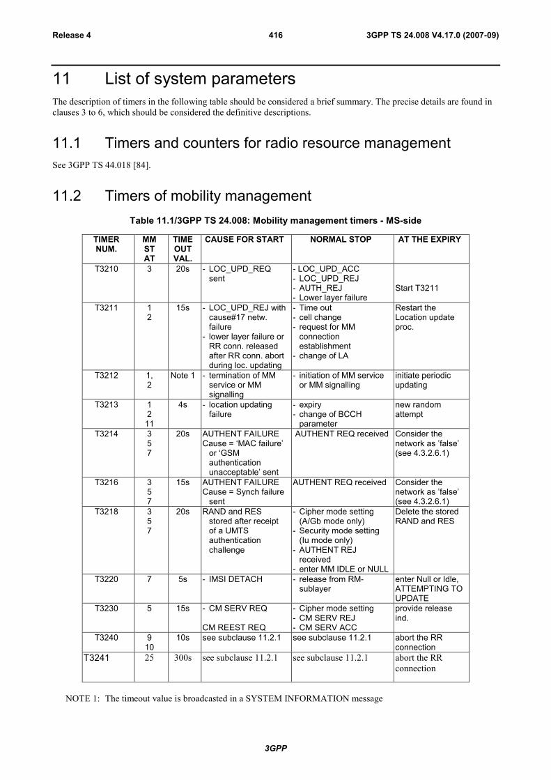
3GPP
3GPP TS 24.008 V4.17.0 (2007-09)Release 4 416
11 List of system parametersThe description of timers in the following table should be considered a brief summary. The precise details are found inclauses 3 to 6, which should be considered the definitive descriptions.
11.1 Timers and counters for radio resource managementSee 3GPP TS 44.018 [84].
11.2 Timers of mobility managementTable 11.1/3GPP TS 24.008: Mobility management timers - MS-side
TIMERNUM.
MMSTAT
TIMEOUTVAL.
CAUSE FOR START NORMAL STOP AT THE EXPIRY
T3210 3 20s - LOC_UPD_REQsent
- LOC_UPD_ACC- LOC_UPD_REJ- AUTH_REJ- Lower layer failure
Start T3211
T3211 12
15s - LOC_UPD_REJ withcause#17 netw.failure
- lower layer failure orRR conn. releasedafter RR conn. abortduring loc. updating
- Time out- cell change- request for MM
connectionestablishment
- change of LA
Restart theLocation updateproc.
T3212 1,2
Note 1 - termination of MMservice or MMsignalling
- initiation of MM serviceor MM signalling
initiate periodicupdating
T3213 12
11
4s - location updatingfailure
- expiry- change of BCCH
parameter
new randomattempt
T3214 357
20s AUTHENT FAILURECause = ‘MAC failure’
or ‘GSMauthenticationunacceptable’ sent
AUTHENT REQ received Consider thenetwork as ’false’(see 4.3.2.6.1)
T3216 357
15s AUTHENT FAILURECause = Synch failure
sent
AUTHENT REQ received Consider thenetwork as ’false’(see 4.3.2.6.1)
T3218 357
20s RAND and RESstored after receiptof a UMTSauthenticationchallenge
- Cipher mode setting(A/Gb mode only)
- Security mode setting(Iu mode only)
- AUTHENT REJreceived
- enter MM IDLE or NULL
Delete the storedRAND and RES
T3220 7 5s - IMSI DETACH - release from RM-sublayer
enter Null or Idle,ATTEMPTING TOUPDATE
T3230 5 15s - CM SERV REQ
CM REEST REQ
- Cipher mode setting- CM SERV REJ- CM SERV ACC
provide releaseind.
T3240 910
10s see subclause 11.2.1 see subclause 11.2.1 abort the RRconnection
T3241 25 300s see subclause 11.2.1 see subclause 11.2.1 abort the RRconnection
NOTE 1: The timeout value is broadcasted in a SYSTEM INFORMATION message

3GPP
3GPP TS 24.008 V4.17.0 (2007-09)Release 4 417
Table 11.2/3GPP TS 24.008: Mobility management timers - network-side
TIMERNUM.
MMSTAT
TIMEOUTVAL.
CAUSE FORSTART
NORMAL STOP AT THE EXPIRY AT THESECONDEXPIRY
T3250 6 12s TMSI-REAL-CMDor LOC UPDACC with newTMSI sent
TMSI-REALL-COMreceived
OptionallyRelease RRconnection
T3255 Note LOC UPD ACCsent with"Followon Proceed"
CM SERVICEREQUEST
Release RRConnection oruse for mobilestationterminating call
T3260 5 12s AUTHENT-REQUEST sent
AUTHENT-RESPONSEreceived
AUTHENT-FAILURE received
OptionallyRelease RRconnection
T3270 4 12s IDENTITYREQUEST sent
IDENTITYRESPONSEreceived
OptionallyRelease RRconnection
NOTE 2: The value of this timer is not specified by this recommendation.
11.2.1 Timer T3240 and Timer T3241Timer T3240 is started in the mobile station when:
- the mobile station receives a LOCATION UPDATING ACCEPT message completing a location updatingprocedure in the cases specified in subclauses 4.4.4.6 and 4.4.4.8;
- the mobile station receives a LOCATION UPDATING REJECT message in the cases specified insubclause 4.4.4.7;
- the mobile station has sent a CM SERVICE ABORT message as specified in subclause 4.5.1.7;
- the mobile station has released or aborted all MM connections in the cases specified in 4.3.2.5, 4.3.5.2, 4.5.1.1,and 4.5.3.1.
Timer T3240 is stopped, reset, and started again at receipt of an MM message.
Timer T3240 is stopped and reset (but not started) at receipt of a CM message that initiates establishment of an CMconnection (an appropriate SETUP, REGISTER, or CP-DATA message as defined in 3GPP TS 24.008, 3GPP TS24.010 or 3GPP TS 24.011).
Timer T3241 is started in the mobile station when entering MM state RR CONNECTION RELEASE NOTALLOWED.
Timer T3241 is stopped and reset (but not started) when the MM state RR CONNECTION RELEASE NOTALLOWED is left.
If timer T3241 expires, the MS shall abort the RR connection and enter the MM state MM IDLE.
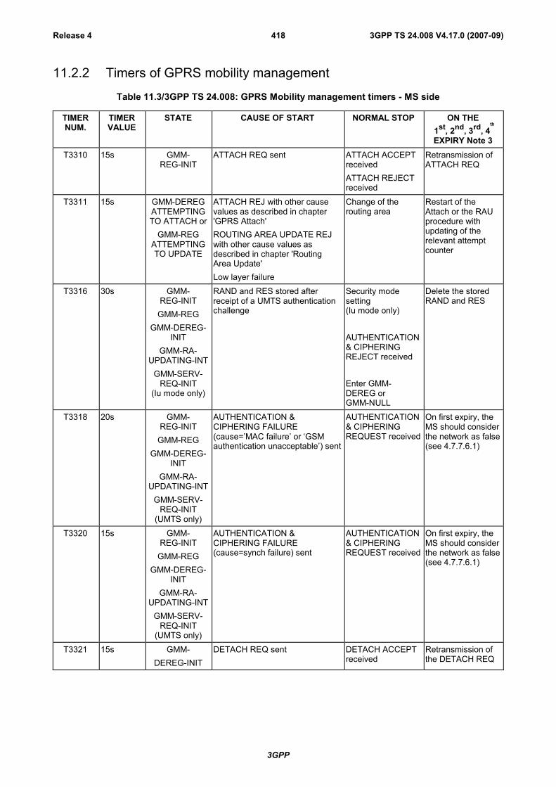
3GPP
3GPP TS 24.008 V4.17.0 (2007-09)Release 4 418
11.2.2 Timers of GPRS mobility management
Table 11.3/3GPP TS 24.008: GPRS Mobility management timers - MS side
TIMERNUM.
TIMERVALUE
STATE CAUSE OF START NORMAL STOP ON THE 1st, 2nd, 3rd, 4
th
EXPIRY Note 3T3310 15s GMM-
REG-INITATTACH REQ sent ATTACH ACCEPT
receivedATTACH REJECTreceived
Retransmission ofATTACH REQ
T3311 15s GMM-DEREGATTEMPTINGTO ATTACH or
GMM-REGATTEMPTINGTO UPDATE
ATTACH REJ with other causevalues as described in chapter'GPRS Attach'ROUTING AREA UPDATE REJwith other cause values asdescribed in chapter 'RoutingArea Update'Low layer failure
Change of therouting area
Restart of theAttach or the RAUprocedure withupdating of therelevant attemptcounter
T3316 30s GMM-REG-INIT
GMM-REGGMM-DEREG-
INITGMM-RA-
UPDATING-INTGMM-SERV-
REQ-INIT(Iu mode only)
RAND and RES stored afterreceipt of a UMTS authenticationchallenge
Security modesetting(Iu mode only)
AUTHENTICATION& CIPHERINGREJECT received
Enter GMM-DEREG orGMM-NULL
Delete the storedRAND and RES
T3318 20s GMM-REG-INIT
GMM-REGGMM-DEREG-
INITGMM-RA-
UPDATING-INTGMM-SERV-
REQ-INIT(UMTS only)
AUTHENTICATION &CIPHERING FAILURE(cause=’MAC failure’ or ‘GSMauthentication unacceptable’) sent
AUTHENTICATION& CIPHERINGREQUEST received
On first expiry, theMS should considerthe network as false(see 4.7.7.6.1)
T3320 15s GMM-REG-INIT
GMM-REGGMM-DEREG-
INITGMM-RA-
UPDATING-INTGMM-SERV-
REQ-INIT(UMTS only)
AUTHENTICATION &CIPHERING FAILURE(cause=synch failure) sent
AUTHENTICATION& CIPHERINGREQUEST received
On first expiry, theMS should considerthe network as false(see 4.7.7.6.1)
T3321 15s GMM-DEREG-INIT
DETACH REQ sent DETACH ACCEPTreceived
Retransmission ofthe DETACH REQ
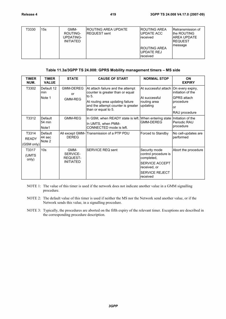
3GPP
3GPP TS 24.008 V4.17.0 (2007-09)Release 4 419
T3330 15s GMM-ROUTING-
UPDATING-INITIATED
ROUTING AREA UPDATEREQUEST sent
ROUTING AREAUPDATE ACCreceived
ROUTING AREAUPDATE REJreceived
Retransmission ofthe ROUTINGAREA UPDATEREQUESTmessage
Table 11.3a/3GPP TS 24.008: GPRS Mobility management timers – MS side
TIMERNUM.
TIMERVALUE
STATE CAUSE OF START NORMAL STOP ONEXPIRY
T3302 Default 12minNote 1
GMM-DEREGor
GMM-REG
At attach failure and the attemptcounter is greater than or equalto 5.At routing area updating failureand the attempt counter is greaterthan or equal to 5.
At successful attach
At successfulrouting areaupdating
On every expiry,initiation of theGPRS attachprocedureorRAU procedure
T3312 Default54 minNote1
GMM-REG In GSM, when READY state is left.In UMTS, when PMM-CONNECTED mode is left.
When entering stateGMM-DEREG
Initiation of thePeriodic RAUprocedure
T3314READY
(GSM only)
Default44 secNote 2
All except GMM-DEREG
Transmission of a PTP PDU Forced to Standby No cell-updates areperformed
T3317(UMTSonly)
10s GMM-SERVICE-REQUEST-INITIATED
SERVICE REQ sent Security modecontrol procedure iscompleted,SERVICE ACCEPTreceived, orSERVICE REJECTreceived
Abort the procedure
NOTE 1: The value of this timer is used if the network does not indicate another value in a GMM signallingprocedure.
NOTE 2: The default value of this timer is used if neither the MS nor the Network send another value, or if theNetwork sends this value, in a signalling procedure.
NOTE 3: Typically, the procedures are aborted on the fifth expiry of the relevant timer. Exceptions are described inthe corresponding procedure description.

3GPP
3GPP TS 24.008 V4.17.0 (2007-09)Release 4 420
Table 11.4/3GPP TS 24.008: GPRS Mobility management timers - network side
TIMERNUM.
TIMERVALUE
STATE CAUSE OF START NORMAL STOP ON THE 1st, 2nd, 3rd, 4th
EXPIRY Note 3T3322 6s GMM-
DEREG-INITDETACH REQ sent DETACH ACCEPT
receivedRetransmission ofDETACHREQUEST
T3350 6s GMM-COMMON-PROC-INIT
ATTACH ACCEPTsent with P-TMSI and/or TMSI
RAU ACCEPT sent with P-TMSIand/or TMSIP-TMSI REALLOC COMMANDsent
ATTACHCOMPLETEreceivedRAU COMPLETEreceivedP-TMSI REALLOCCOMPLETEreceived
Retransmission ofthe same messagetype, i.e. ATTACHACCEPT, RAUACCEPT orREALLOCCOMMAND
T3360 6s GMM-COMMON-PROC-INIT
AUTH AND CIPH REQUESTsent
AUTH AND CIPHRESPONSEreceivedAUTHENT-ANDCIPHER-FAILUREreceived
Retransmission ofAUTH AND CIPHREQUEST
T3370 6s GMM-COMMON-PROC-INIT
IDENTITY REQUEST sent IDENTITYRESPONSEreceived
Retransmission ofIDENTITYREQUEST
Table 11.4a/3GPP TS 24.008: GPRS Mobility management timers - network side
TIMERNUM.
TIMERVALUE
STATE CAUSE OF START NORMAL STOP ONEXPIRY
T3313 Note1 GMM_REG Paging procedure initiated Paging procedurecompleted
Network dependent
T3314READY
(GSM only)
Default44 secNote 2
All except GMM-DEREG
Receipt of a PTP PDU Forced to Standby The network shallpage the MS if a
PTP PDU has to besent to the MS
MobileReachable
Default 4min greaterthan T3312
All except GMM-DEREG
In GSM, change from READY toSTANDBY state
In UMTS, change from PMM-CONNECTED mode to PMM-IDLE
mode.
PTP PDU received Network dependentbut typically paging
is halted on 1stexpiry
NOTE 1: The value of this timer is network dependent.
NOTE 2: The default value of this timer is used if neither the MS nor the Network send another value, or if theNetwork sends this value, in a signalling procedure. The value of this timer should be slightly shorter inthe network than in the MS, this is a network implementation issue.
NOTE 3: Typically, the procedures are aborted on the fifth expiry of the relevant timer. Exceptions are described inthe corresponding procedure description.

3GPP
3GPP TS 24.008 V4.17.0 (2007-09)Release 4 421
11.2.3 Timers of session management
Table 11.2c/3GPP TS 24.008: Session management timers - MS side
TIMERNUM.
TIMERVALUE
STATE CAUSE OF START NORMAL STOP ON THE 1st, 2nd, 3rd, 4th
EXPIRYT3380 30s PDP-
ACTIVE-PENDACTIVATE PDP CONTEXTREQUEST or ACTIVATESECONDARY PDP CONTEXTREQUEST sent
ACTIVATEPDP CONTEXTACCEPT orACTIVATESECONDARY PDPCONTEXTACCEPT receivedACTIVATEPDP CONTEXTREJECT orACTIVATESECONDARY PDPCONTEXTREJECT received
Retransmission ofACTIVATE PDPCONTEXT REQ orACTIVATESECONDARY PDPCONTEXTREQUEST
T3381 8s PDP-MODIFY-PENDING
MODIFY PDP CONTEXTREQUEST sent
MODIFY PDPCONTEXTACCEPT received
Retransmission ofMODIFY PDPCONTEXTREQUEST
T3390 8s PDP-INACT-PEND
DEACTIVATE PDP CONTEXTREQUEST sent
DEACTIVATE PDPCONTEXT ACCreceived
Retransmission ofDEACTIVATEPDP CONTEXTREQUEST
NOTE: Typically, the procedures are aborted on the fifth expiry of the relevant timer. Exceptions are described inthe corresponding procedure description.
Table 11.2d/3GPP TS 24.008: Session management timers - network side
TIMERNUM.
TIMERVALUE
STATE CAUSE OF START NORMAL STOP ON THE 1st, 2nd, 3rd, 4th
EXPIRYT3385 8s PDP-
ACT-PENDREQUEST PDP CONTEXTACTIVATION sent
ACTIVATE PDPCONTEXT REQreceived
Retransmission ofREQUEST PDPCONTEXTACTIVATION
T3386 8s PDP-MOD-PEND
MODIFY PDP CONTEXTREQUEST sent
MODIFY PDPCONTEXT ACCreceived
Retransmission ofMODIFY PDPCONTEXT REQ
T3395 8s PDP-INACT-PEND
DEACTIVATE PDP CONTEXTREQUEST sent
DEACTIVATE PDPCONTEXT ACCreceived
Retransmission ofDEACTIVATE PDPCONTEXT REQ
NOTE: Typically, the procedures are aborted on the fifth expiry of the relevant timer. Exceptions are described inthe corresponding procedure description.
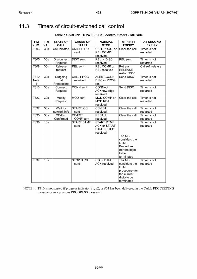
3GPP
3GPP TS 24.008 V4.17.0 (2007-09)Release 4 422
11.3 Timers of circuit-switched call controlTable 11.3/3GPP TS 24.008: Call control timers - MS side
TIMNUM.
TIMVAL
STATE OFCALL
CAUSE OFSTART
NORMALSTOP
AT FIRSTEXPIRY
AT SECONDEXPIRY
T303 30s Call initiated CM SER RQsent
CALL PROC, orREL COMPreceived
Clear the call Timer is notrestarted
T305 30s DisconnectRequest
DISC sent REL or DISCreceived
REL sent. Timer is notrestarted
T308 30s Releaserequest
REL sent REL COMP orREL received
Retrans.RELEASErestart T308
Call ref. release
T310Note
1
30s Outgoingcall
Proceeding
CALL PROCreceived
ALERT,CONN,DISC or PROGrec.
Send DISC Timer is notrestarted
T313 30s ConnectRequest
CONN sent CONNectACKnowledgereceived
Send DISC Timer is notrestarted
T323 30s ModifyRequest
MOD sent MOD COMP orMOD REJreceived
Clear the call Timer is notrestarted
T332 30s Wait fornetwork info
START_CCsent
CC-EST.received
Clear the call Timer is notrestarted
T335 30s CC-Est.Confirmed
CC-ESTCONF.sent
RECALLreceived
Clear the call Timer is notrestarted
T336 10s START DTMFsent
START DTMFACK or STARTDTMF REJECTreceived
Timer is notrestarted
The MSconsiders theDTMFProcedure(for the digit)to beterminated
T337 10s STOP DTMFsent
STOP DTMFACK received
The MSconsiders theDTMFprocedure (forthe currentdigit) to beterminated
Timer is notrestarted
NOTE 1: T310 is not started if progress indicator #1, #2, or #64 has been delivered in the CALL PROCEEDINGmessage or in a previous PROGRESS message.

3GPP
3GPP TS 24.008 V4.17.0 (2007-09)Release 4 423
Table 11.4/3GPP TS 24.008: Call control timers - network side
TIMNUM.
DFTTIMVAL
STATE OFCALL
CAUSE FORSTART
NORMALSTOP
AT FIRSTEXPIRY
AT SECONDEXPIRY
T301Note
1
Min180s
Callreceived
ALERTreceived
CONN received Clear the call Timer is notrestarted
T303 Note 2 Call present SETUP sent CALL CONF orREL COMPreceived
Clear the call Timer is notrestarted
T305 30s DisconnectIndication
DISC withoutprogressindic. #8sent orCCBSPossible
REL or DISCreceived
NetworksendsRELEASE
Timer is notrestarted
T306 30s DisconnectIndication
DISC withprogressindic. #8sent but noCCBSpossible
REL or DISCreceived
Stop the tone/announc.Send REL
Timer is notrestarted
T308 Note 2 Releaserequest
REL sent REL COMP orREL received
Retrans.RELEASErestart T308
Release callreference
T310 Note 2 Incomingcall
proceeding
CALL CONFreceived
ALERT, CONNor DISCreceived
Clear the call Timer is notrestarted
T313 Note 2 ConnectIndication
CON sent CON ACKreceived
Clear the call Timer is notrestarted
T323 30s Modifyrequest
MOD sent MOD COMP orMOD REJreceived
Clear the call Timer is notrestarted
T331 Note 2 CC Connec.Pending
CM-SERVPROMPTsent
START CCreceived
Clear the call Timer is notrestarted
T333 Note 2 CC-Est.Present
START CCreceived
CC-EST.CONFor REL COMPreceived
Clear the call Timer is notrestarted
T334Note
3
Min15s
CC-Est.Confirmed
RECALL sent SETUPreceived
Clear the call Timer is notrestarted
T338 Note 2 Disconnectindication
DISC withCCBSpossible
REL or DISCreceived
stop any tone/announc.Send REL
Timer is notrestarted
NOTE 1: The network may already have applied an internal alerting supervision function; e.g. incorporated withincall control. If such a function is known to be operating on the call, then timer T301 is not used.
NOTE 2: These time values are set by the network operator.
NOTE 3: When applied to the supplementary service CCBS, the timer T334 can either represent the recall timer T4or the notification timer T10 (see 3GPP TS 23.093). Thus the timer T334 can take two different values.3GPP TS 23.093 defines the range of these values.
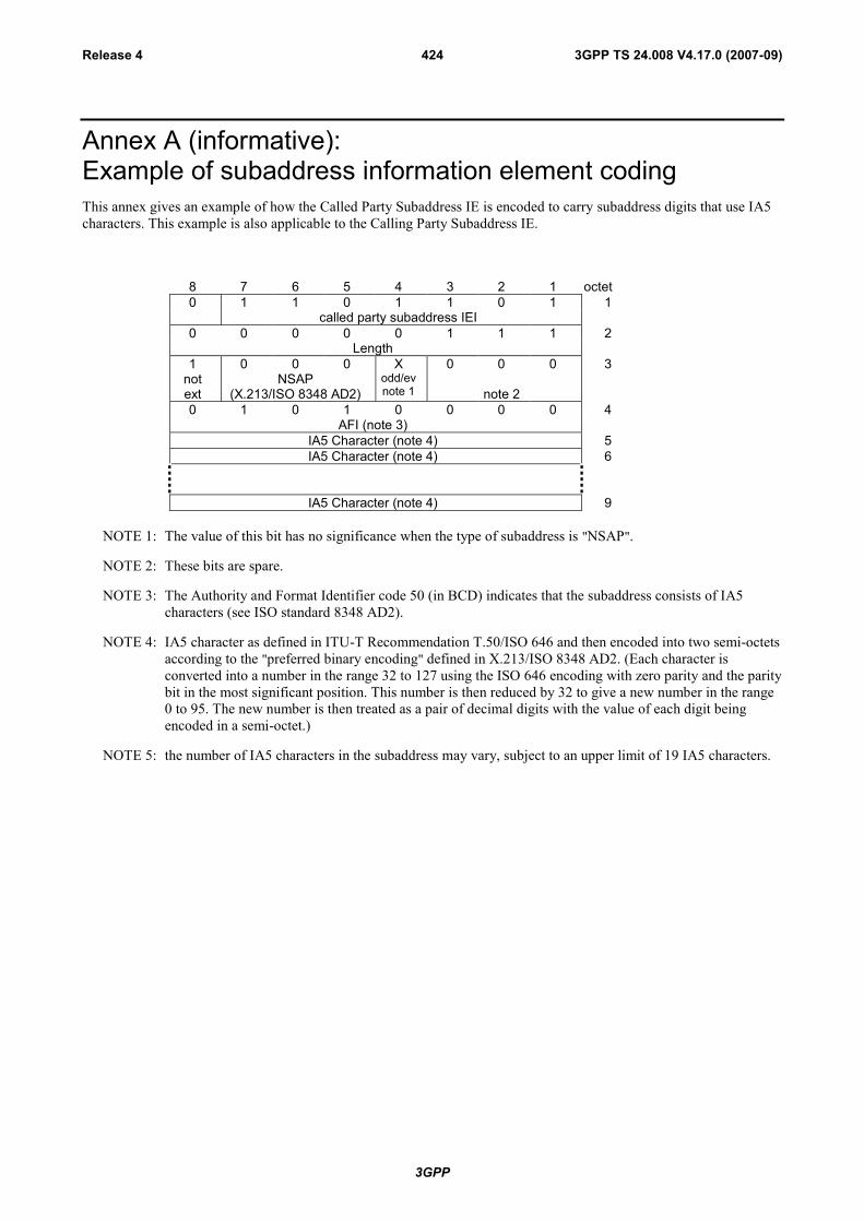
3GPP
3GPP TS 24.008 V4.17.0 (2007-09)Release 4 424
Annex A (informative):Example of subaddress information element codingThis annex gives an example of how the Called Party Subaddress IE is encoded to carry subaddress digits that use IA5characters. This example is also applicable to the Calling Party Subaddress IE.
8 7 6 5 4 3 2 1 octet0 1 1 0 1 1 0 1 1
called party subaddress IEI0 0 0 0 0 1 1 1 2
Length1 0 0 0 X 0 0 0 3
notext
NSAP(X.213/ISO 8348 AD2)
odd/evnote 1 note 2
0 1 0 1 0 0 0 0 4AFI (note 3)
IA5 Character (note 4) 5IA5 Character (note 4) 6
IA5 Character (note 4) 9
NOTE 1: The value of this bit has no significance when the type of subaddress is "NSAP".
NOTE 2: These bits are spare.
NOTE 3: The Authority and Format Identifier code 50 (in BCD) indicates that the subaddress consists of IA5characters (see ISO standard 8348 AD2).
NOTE 4: IA5 character as defined in ITU-T Recommendation T.50/ISO 646 and then encoded into two semi-octetsaccording to the "preferred binary encoding" defined in X.213/ISO 8348 AD2. (Each character isconverted into a number in the range 32 to 127 using the ISO 646 encoding with zero parity and the paritybit in the most significant position. This number is then reduced by 32 to give a new number in the range0 to 95. The new number is then treated as a pair of decimal digits with the value of each digit beingencoded in a semi-octet.)
NOTE 5: the number of IA5 characters in the subaddress may vary, subject to an upper limit of 19 IA5 characters.
3GPP
3GPP TS 24.008 V4.17.0 (2007-09)Release 4 425
Annex B (normative):Compatibility checking
B.1 IntroductionThis annex describes the various compatibility checks which shall be carried out to ensure that the best matched MS andnetwork capabilities are achieved on a call between a PLMN and the ISDN.
Three different processes of compatibility checking shall be performed:
i) at the user-to-network interface on the calling side (see B.2);
ii) at the network-user interface on the called side (see B.3.2);
iii) user-to-user (see B 3.3).
NOTE: In this context and throughout this annex the term "called user" is the end point entity which is explicitlyaddressed.
For details on the coding of the information required for compatibility checking, see annex C.
B.2 Calling side compatibility checking
B.2.1 Compatibility checking of the CM SERVICE REQUESTmessage
The network shall check if the service requested in the CM SERVICE REQUEST message is permitted for thatsubscriber.
B.2.2 Compatibility/Subscription checking of the SETUP messageAt the calling side the network shall check that the basic service(s) requested by the calling MS in the Bearer Capabilityinformation element(s) match(es) with the basic services provided to that subscriber by the PLMN. If for at least onebearer capability information element contained in the SETUP message a mismatch is detected, then the network shallproceed as follows:
- if the SETUP message contained two bearer capability information elements for only one of which a mismatch isdetected, the network shall either:
- under the conditions specified in 3GPP TS 27.001 (e.g. TS 61 and TS 62), accept the SETUP message with aCALL PROCEEDING message containing the, possibly negotiated, bearer capability information elementfor which no mismatch is detected, or
- reject the call using one of the causes listed in annex H.
- otherwise the network shall reject the call using one of the causes listed in annex H.
Network services are described in 3GPP TS 22.002 and 3GPP TS 22.003 [4] as bearer services and teleservices,respectively.
B.3 Called side compatibility checkingIn this clause, the word "check" means that the MS examines the contents of the specified information element.
3GPP
3GPP TS 24.008 V4.17.0 (2007-09)Release 4 426
B.3.1 Compatibility checking with addressing informationIf an incoming SETUP message is offered to the MS with addressing information (i.e. sub-address or called partynumber) the following shall occur:
a) if the MS has a DDI number or a sub-address, then the information in any Called Party BCD Number or anyCalled Party subaddress information elements of the incoming SETUP message shall be checked by the MSagainst the corresponding part of the number assigned to the user (e.g. for DDI) or the user's own sub-address.
In the cases of a mismatch, the MS shall release the call. In the case of a match, the compatibility checkingdescribed in B.3.2 and B.3.3 shall be performed.
b) if the MS has no DDI number and no sub-address, then the Called Party BCD Number and Called Party Sub-address information element shall be ignored for the purposes of compatibility checking. The compatibilitychecking described in B.3.2 and B.3.3 shall be performed.
NOTE: According to the user's requirements, compatibility checking can be performed in various ways from theviewpoint of execution order and information to be checked, e.g. first DDI number/sub-address and thenbearer capability or vice versa.
B.3.2 Network-to-MS compatibility checkingWhen the network is providing a basic service at the called side, the MS shall check that the basic service(s) offered bythe network in the Bearer Capability information element(s) match(es) the basic services that the MS is able to support.If a mismatch is detected, then the MS shall proceed as follows:
- if the SETUP message contained two bearer capability information elements for only one of which a mismatch isdetected, the MS shall either:
- under the conditions specified in 3GPP TS 27.001 [36] (e.g. TS 61 and TS 62), accept the SETUP messagewith a CALL CONFIRMED message containing the, possibly negotiated, bearer capability informationelement for which no mismatch is detected, or
- reject the call using cause No. 88 "incompatible destination".
- otherwise the MS shall reject the offered call using a RELEASE COMPLETE message with cause No. 88"incompatible destination".
When interworking with existing networks, limitations in network or distant user signalling (e.g. in the case of anincoming call from a PSTN or a call from an analogue terminal) may restrict the information available to the called MSin the incoming SETUP message (e.g. missing Bearer Capability Information Element or missing High LayerCompatibility Information Element). For compatibility checking, and handling of such calls see 3GPP TS 27.001 [36].
B.3.3 User-to-User compatibility checkingSee 3GPP TS 27.001 [36].
B.4 High layer compatibility checkingSee 3GPP TS 27.001 [36].
3GPP
3GPP TS 24.008 V4.17.0 (2007-09)Release 4 427
Annex C (normative):Low layer information coding principles
C.1 PurposeThis annex describes principles that shall be used when the calling MS specifies information during call setup regardinglow layer capabilities required in the network and by the destination terminal. Refer also to 3GPP TS 27.001 [36].
NOTE: In this context and throughout this annex the term "called user" is the end point entity which is explicitlyaddressed. This may also be an explicitly addressed interworking unit (IWU) (see ITU-T I.500-SeriesRecommendations and ITU-T Recommendation X.31 case a).
C.2 Principles
C.2.1 Definition of types of informationThere are three different types of information that the calling PLMN user may specify during call setup to identify lowlayer capabilities needed in the network and in the destination terminal:
a) type I information is information about the calling terminal which is only used at the destination end to allow adecision regarding terminal compatibility. An example would be the user information layer 3 protocol. Type Iinformation is encoded in octets 5 to 7 of the low layer compatibility information element;
b) type II information is only used by the network (PLMN) to which the calling user is connected for selection ofPLMN specific network resources, e.g. channel type or specific functionality within the interworking function(IWF, see 3GPP TS 29.007). This type of information is always present. An example is the connection element.Type II information is coded in:
i) octet 3 of the bearer capability information element when the information transfer capability required by thecalling user is speech ;
ii) octets 3, 4, 5, and optionally octet 7 of the bearer capability information element when the informationtransfer capability required by the calling user is not speech;
c) type III information is required for selection of a basic service from the choice of basic services offered by thenetwork and together with type II information for selection of an appropriate interworking function (IWF, see3GPP TS 29.007 [38]), as well as for terminal compatibility checking at the destination terminal. An example isthe information transfer capability. Type III information is always present and is encoded in:
i) octet 3 of the bearer capability information element when the information transfer capability required by thecalling user is speech ;
ii) octets 3, 5, 6, 6a, 6b and 6c of the bearer capability information element when the information transfercapability required by the calling user is not speech;
C.2.2 Examination by networkType I information is user-to-user (i.e. at the calling side not examined by network) while type II and III informationshould be available for examination by the destination user and the network.
NOTE: In the case of a mobile terminated call, if the type II and type III information is not sufficient for theselection of an appropriate interworking function, the type I information will also examined by thenetwork.
3GPP
3GPP TS 24.008 V4.17.0 (2007-09)Release 4 428
C.2.3 Location of type I informationType I information (i.e. terminal information only significant to the called user) shall, when used, be included in the lowlayer compatibility information element.
C.2.4 Location of types II and III informationType II information is included in the bearer capability information element. Type III information is also included in thebearer capability information element. The network may use and modify type III information (e.g. to provideinterworking).
In any case a modification of the bearer capability information element has to be performed when interworking to thefixed network (e.g. ISDN) is required, where the signalling of the radio interface has to be mapped to fixed networksignalling (e.g. mapping of GSM BCIE to ISDN BCIE, see 3GPP TS 29.007 [38]).
C.2.5 Relationship between bearer capability and low layercompatibility information elements
There shall be no contradiction of information between the low layer compatibility and the bearer capability at theoriginating side. However, as some bearer capability code points may be modified during the transport of the call (e.g.by the interworking function), this principle implies that there should be minimal duplication of information betweenthe bearer capability information element and the low layer compatibility information element.
NOTE: If as a result of duplication, a contradiction occurs at the terminating side between the bearer capabilityinformation element and the low layer compatibility information element at the terminating side, thereceiving entity shall ignore the conflicting information in the low layer compatibility informationelement.

3GPP
3GPP TS 24.008 V4.17.0 (2007-09)Release 4 429
Annex D (informative):Examples of bearer capability information element codingThis annex gives examples of the coding of bearer capability information elements for various telecommunicationservices. This annex is included for information purposes only. In the case of any inconsistency between this annex and3GPP TS 27.001 [36], then 3GPP TS 27.001 shall take precedence over this annex.
D.1 Coding for speech for a full rate support only mobilestation
D.1.1 Mobile station to network direction
8 7 6 5 4 3 2 10 0 0 0 0 1 0 0 octet 1
Bearer capability IEI0 0 0 0 0 0 0 1
Length of the bearer capability contents octet 21 0 1 0 0 0 0 0
notext
full rateonly
GSM circ.mode
speech octet 3
D.1.2 Network to mobile station direction
8 7 6 5 4 3 2 10 0 0 0 0 1 0 0 octet 1
Bearer capability IEI0 0 0 0 0 0 0 1
Length of the bearer capability contents octet 21 0 1 0 0 0 0 0
notext
spare spare GSM circ.mode
speech octet 3
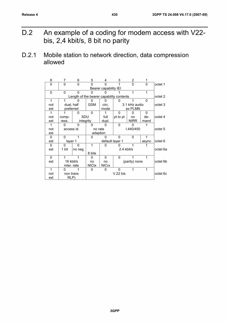
3GPP
3GPP TS 24.008 V4.17.0 (2007-09)Release 4 430
D.2 An example of a coding for modem access with V22-bis, 2,4 kbit/s, 8 bit no parity
D.2.1 Mobile station to network direction, data compressionallowed
8 7 6 5 4 3 2 10 0 0 0 0 1 0 0 octet 1
Bearer capability IEI0 0 0 0 0 1 1 1
Length of the bearer capability contents octet 21 1 0 0 0 0 1 0
notext
dual, halfpreferred
GSM circ.mode
3.1 kHz audioex PLMN
octet 3
1 1 0 0 1 0 0 0notext
comp-ress.
SDUintegrity
fulldupl.
pt to pt noNIRR
de-mand
octet 4
1 0 0 0 0 0 0 1notext
access id. no rateadaption
I.440/450 octet 5
0 0 1 0 0 0 0 1ext layer 1 default layer 1 async octet 60 0 0 1 0 0 1 1
ext 1 bit no neg8 bits
2.4 kbit/s octet 6a
0 1 1 0 0 0 1 1ext 16 kbit/s
inter. rateno
NICtxno
NICrx(parity) none octet 6b
1 0 1 0 0 0 1 1notext
non transRLP)
V.22 bis octet 6c

3GPP
3GPP TS 24.008 V4.17.0 (2007-09)Release 4 431
D.2.2 Network to mobile station direction, data compressionpossible
8 7 6 5 4 3 2 10 0 0 0 0 1 0 0 octet 1
Bearer capability IEI0 0 0 0 0 1 1 1
Length of the bearer capability contents octet 21 0 1 0 0 0 1 0
notext
spare spare GSM circ.mode
3.1 kHz audioex PLMN
octet 3
1 1 0 0 1 0 0 0notext
comp-ress.
SDUintegrity
fulldupl.
pt to pt noNIRR
de-mand
octet 4
1 0 0 0 0 0 0 1notext
access id. no rateadaption
I.440/450 octet 5
0 0 1 0 0 0 0 1ext layer 1 default layer 1 async octet 60 0 0 1 0 0 1 1
ext 1 bit noneg
8 bits 2.4 kbit/s octet 6a
0 1 1 0 0 0 1 1ext 16 kbit/s
inter. rateno
NICtxno
NICrx(parity) none octet 6b
1 0 1 0 0 0 1 1notext
non trans(RLP)
V.22 bis octet 6c

3GPP
3GPP TS 24.008 V4.17.0 (2007-09)Release 4 432
D.3 An example of a coding for group 3 facsimile (9,6kbit/s, transparent)
D.3.1 Mobile station to network direction
8 7 6 5 4 3 2 10 0 0 0 0 1 0 0 octet 1
Bearer capability IEI0 0 0 0 0 1 1 1
Length of the bearer capability contents octet 21 0 1 0 0 0 1 1
notext
full rateonly MS
GSM circ.mode
facsimilegroup 3
octet 3
1 0 1 1 1 0 0 0notext
comp-ress.
unstructured fulldupl.
pt topt
noNIRR
de-mand
octet 4
1 0 0 0 0 0 0 1notext
access id. no rateadaption
I.440/450 octet 5
0 0 1 0 0 0 0 0ext layer 1 default layer 1 sync octet 60 0 0 1 0 1 0 1
ext (syn) noneg
(syn) 9.6 kbit/s octet 6a
0 1 1 0 0 0 1 1ext 16 kbit/s
inter. rateno
NICtxno
NICrx(parity) none octet 6b
1 0 0 0 0 0 1 1notext
transparent none(modem type)
octet 6c

3GPP
3GPP TS 24.008 V4.17.0 (2007-09)Release 4 433
D.3.2 Network to mobile station direction
8 7 6 5 4 3 2 10 0 0 0 0 1 0 0 octet 1
Bearer capability IEI0 0 0 0 0 1 1 1
Length of the bearer capability contents octet 21 0 1 0 0 0 1 1
notext
spare spare GSM circ.mode
facsimilegroup 3
octet 3
1 0 1 1 1 0 0 0notext
comp-ress.
unstructured fulldupl.
pt topt
noNIRR
de-mand
octet 4
1 0 0 0 0 0 0 1notext
access id. no rateadaption
I.440/450 octet 5
0 0 1 0 0 0 0 0ext layer 1 default layer 1 sync octet 60 0 0 1 0 1 0 1
ext (syn) noneg
(syn) 9.6 kbit/s octet 6a
0 1 1 0 0 0 1 1ext 16 kbit/s
inter. rateno
NICtxno
NICrx(parity) none octet 6b
1 0 0 0 0 0 0 0notext
transparent none(modem type)
octet 6c
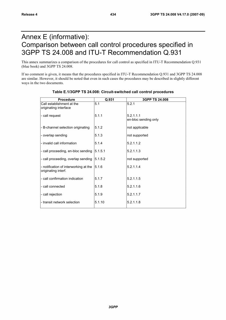
3GPP
3GPP TS 24.008 V4.17.0 (2007-09)Release 4 434
Annex E (informative):Comparison between call control procedures specified in3GPP TS 24.008 and ITU-T Recommendation Q.931This annex summarizes a comparison of the procedures for call control as specified in ITU-T Recommendation Q.931(blue book) and 3GPP TS 24.008.
If no comment is given, it means that the procedures specified in ITU-T Recommendation Q.931 and 3GPP TS 24.008are similar. However, it should be noted that even in such cases the procedures may be described in slightly differentways in the two documents.
Table E.1/3GPP TS 24.008: Circuit-switched call control procedures
Procedure Q.931 3GPP TS 24.008Call establishment at theoriginating interface
5.1 5.2.1
- call request 5.1.1 5.2.1.1.1en-bloc sending only
- B-channel selection originating 5.1.2 not applicable
- overlap sending 5.1.3 not supported
- invalid call information 5.1.4 5.2.1.1.2
- call proceeding, en-bloc sending 5.1.5.1 5.2.1.1.3
- call proceeding, overlap sending 5.1.5.2 not supported
- notification of interworking at theoriginating interf.
5.1.6 5.2.1.1.4
- call confirmation indication 5.1.7 5.2.1.1.5
- call connected 5.1.8 5.2.1.1.6
- call rejection 5.1.9 5.2.1.1.7
- transit network selection 5.1.10 5.2.1.1.8
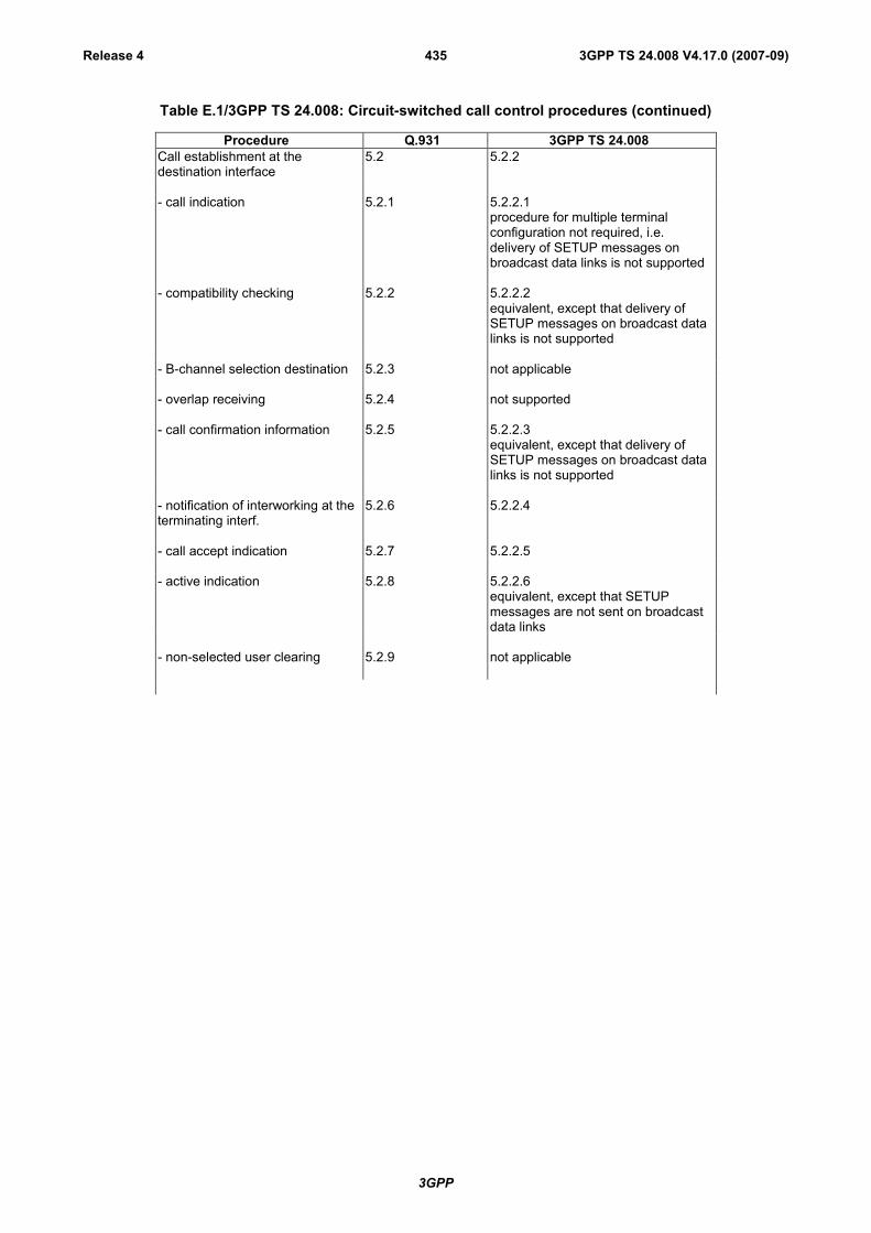
3GPP
3GPP TS 24.008 V4.17.0 (2007-09)Release 4 435
Table E.1/3GPP TS 24.008: Circuit-switched call control procedures (continued)
Procedure Q.931 3GPP TS 24.008Call establishment at thedestination interface
5.2 5.2.2
- call indication 5.2.1 5.2.2.1procedure for multiple terminalconfiguration not required, i.e.delivery of SETUP messages onbroadcast data links is not supported
- compatibility checking 5.2.2 5.2.2.2equivalent, except that delivery ofSETUP messages on broadcast datalinks is not supported
- B-channel selection destination 5.2.3 not applicable
- overlap receiving 5.2.4 not supported
- call confirmation information 5.2.5 5.2.2.3equivalent, except that delivery ofSETUP messages on broadcast datalinks is not supported
- notification of interworking at theterminating interf.
5.2.6 5.2.2.4
- call accept indication 5.2.7 5.2.2.5
- active indication 5.2.8 5.2.2.6equivalent, except that SETUPmessages are not sent on broadcastdata links
- non-selected user clearing 5.2.9 not applicable

3GPP
3GPP TS 24.008 V4.17.0 (2007-09)Release 4 436
Table E.1/3GPP TS 24.008: Circuit-switched call control procedures (continued)
Procedure Q.931 3GPP TS 24.008Call clearing 5.3 5.4
- terminology 5.3.1 5.4.1terminology adapted to GSMapplications
- exception conditions 5.3.2 5.4.2only case a) of clause 5.3.2 of Rec.Q.931 applies. All other exceptionsapply to functions which are notrelevant to GSM
- clearing initiated by the user/MS 5.3.3 5.4.3
- clearing initiated by the network 5.3.4 5.4.4
- clearing whentones/announcements areprovided
5.3.4.1 5.4.4.1.1 and 5.4.4.2.1exception: if not already connected,the traffic channel is connected inorder to provide thetone/announcement
- clearing whentones/announcements are notprovided
5.3.4.2 5.4.4.1.2 and 5.4.4.2.3
- completion of clearing 5.3.4.3 5.4.4.1.3 and 5.4.4.2.5
Clear collision 5.3.5 5.4.5
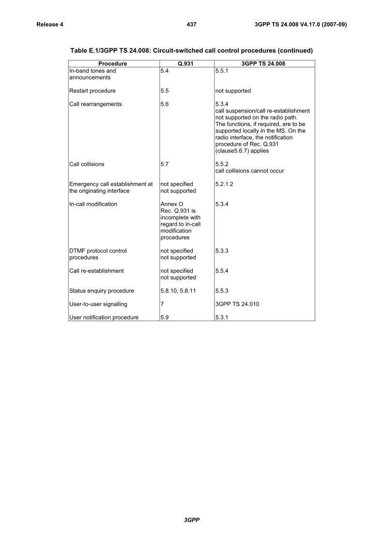
3GPP
3GPP TS 24.008 V4.17.0 (2007-09)Release 4 437
Table E.1/3GPP TS 24.008: Circuit-switched call control procedures (continued)
Procedure Q.931 3GPP TS 24.008In-band tones andannouncements
5.4 5.5.1
Restart procedure 5.5 not supported
Call rearrangements 5.6 5.3.4call suspension/call re-establishmentnot supported on the radio path.The functions, if required, are to besupported locally in the MS. On theradio interface, the notificationprocedure of Rec. Q.931(clause5.6.7) applies
Call collisions 5.7 5.5.2call collisions cannot occur
Emergency call establishment atthe originating interface
not specifiednot supported
5.2.1.2
In-call modification Annex ORec. Q.931 isincomplete withregard to in-callmodificationprocedures
5.3.4
DTMF protocol controlprocedures
not specifiednot supported
5.3.3
Call re-establishment not specifiednot supported
5.5.4
Status enquiry procedure 5.8.10, 5.8.11 5.5.3
User-to-user signalling 7 3GPP TS 24.010
User notification procedure 5.9 5.3.1
3GPP
3GPP TS 24.008 V4.17.0 (2007-09)Release 4 438
Annex F (informative):GSM specific cause values for radio resource managementSee 3GPP TS 44.018 [84].

3GPP
3GPP TS 24.008 V4.17.0 (2007-09)Release 4 439
Annex G (informative):UMTS specific cause values for mobility managementThis annex describes the cause values for the mobility management procedures for non-GPRS services (MM) andGPRS services (GMM). Clauses G1 to G5 are valid for both MM and GMM. However, the following codes areapplicable for non-GPRS services only:
#38 Call cannot be identified
Clause G.6 applies only for GMM procedures.
G.1 Causes related to MS identificationCause value = 2 IMSI unknown in HLR
This cause is sent to the MS if the MS is not known (registered) in the HLR. This cause code does not affectoperation of the GPRS service, although is may be used by a GMM procedure.
Cause value = 3 Illegal MS
This cause is sent to the MS when the network refuses service to the MS either because an identity of the MS isnot acceptable to the network or because the MS does not pass the authentication check, i.e. the SRES receivedfrom the MS is different from that generated by the network. When used by an MM procedure, except theauthentication procedure, this cause does not affect operation of the GPRS service.
Cause value = 4 IMSI unknown in VLR
This cause is sent to the MS when the given IMSI is not known at the VLR.
Cause value = 5 IMEI not accepted
This cause is sent to the MS if the network does not accept emergency call establishment using an IMEI.
Cause value = 6 Illegal ME
This cause is sent to the MS if the ME used is not acceptable to the network, e.g. blacklisted. When used by anMM procedure, this cause does not affect operation of the GPRS service.
G.2 Cause related to subscription optionsCause value = 11 PLMN not allowed
This cause is sent to the MS if it requests location updating in a PLMN where the MS, by subscription or due tooperator determined barring is not allowed to operate.
Cause value = 12 Location Area not allowed
This cause is sent to the MS if it requests location updating in a location area where the MS, by subscription, isnot allowed to operate.
Cause value = 13 Roaming not allowed in this location area
This cause is sent to an MS which requests location updating in a location area of a PLMN which offers roamingto that MS in that Location Area, by subscription.
Cause value = 15 No Suitable Cells In Location Area
This cause is sent to the MS if it requests location updating in a location area where the MS, by subscription, isnot allowed to operate, but when it should find another allowed location area in the same PLMN.

3GPP
3GPP TS 24.008 V4.17.0 (2007-09)Release 4 440
NOTE: Cause #15 and cause #12 differ in the fact that cause #12 does not trigger the MS to search for anotherallowed location area on the same PLMN.
G.3 Causes related to PLMN specific network failuresand congestion/Authentication Failures
Cause value = 20 MAC failure
This cause is sent to thenetwork if the SIM detects that the MAC in the authentication request message is notfresh (see 3GPP TS 33.102).
Cause value = 21 Synch failure
This cause is sent to the network if the SIM detects that the SQN in the authentication request message is out ofrange (see 3GPP TS 33.102).
Cause value = 17 Network failure
This cause is sent to the MS if the MSC cannot service an MS generated request because of PLMN failures, e.g.problems in MAP.
Cause value = 22 Congestion
This cause is sent if the service request cannot be actioned because of congestion (e.g. no channel, facilitybusy/congested etc.).
Cause value = 23 GSM authentication unacceptable
This cause is sent to the network in UMTS if the MS supports the UMTS authentication algorithm and there isno Authentication Parameter AUTN IE present in the AUTHENTICATION REQUEST message.
G.4 Causes related to nature of requestCause value = 32 Service option not supported
This cause is sent when the MS requests a service/facility in the CM SERVICE REQUEST message which is notsupported by the PLMN.
Cause value = 33 Requested service option not subscribed
This cause is sent when the MS requests a service option for which it has no subscription.
Cause value = 34 Service option temporarily out of order
This cause is sent when the MSC cannot service the request because of temporary outage of one or morefunctions required for supporting the service.
Cause value = 38 Call cannot be identified
This cause is sent when the network cannot identify the call associated with a call re-establishment request.
G.5 Causes related to invalid messagesCause value = 95 Semantically incorrect message.
See annex H, subclause H.5.10.
Cause value = 96 Invalid mandatory information.
See annex H, subclause H.6.1.
3GPP
3GPP TS 24.008 V4.17.0 (2007-09)Release 4 441
Cause value = 97 Message type non-existent or not implemented.
See annex H, subclause H.6.2.
Cause value = 98 Message not compatible with protocol state.
See annex H, subclause H.6.3.
Cause value = 99 Information element non-existent or not implemented.
See annex H, subclause H.6.4.
Cause value = 100 Conditional IE error.
See annex H, subclause H.6.5.
Cause value = 101 Message not compatible with protocol state.
See annex H, subclause H.6.6.
Cause value = 111 Protocol error, unspecified.
See annex H, subclause H.6.8.
G.6 Additional cause codes for GMMCause value = 7 GPRS services not allowed
This cause is sent to the MS if it requests an IMSI attach for GPRS services, but is not allowed to operate GPRSservices.
Cause value = 8 GPRS services and non-GPRS services not allowed
This cause is sent to the MS if it requests a combined IMSI attach for GPRS and non-GPRS services, but is notallowed to operate either of them.
Cause value = 9 MS identity cannot be derived by the network
This cause is sent to the MS when the network cannot derive the MS's identity from the P-TMSI in case of inter-SGSN routing area update.
Cause value = 10 Implicitly detached
This cause is sent to the MS either if the network has implicitly detached the MS, e.g. some while after theMobile reachable timer has expired, or if the GMM context data related to the subscription dose not exist in theSGSN e.g. because of a SGSN restart.
Cause value = 14 GPRS services not allowed in this PLMN
This cause is sent to the MS which requests GPRS service in a PLMN which does not offer roaming for GPRSservices to that MS.
Cause value = 16 MSC temporarily not reachable
This cause is sent to the MS if it requests a combined GPRS attach or routing are updating in a PLMN where theMSC is temporarily not reachable via the GPRS part of the GSM network.
Cause value = 40 No PDP context activated
This cause is sent to the MS if the MS requests an establishment of the radio access bearers for all active PDPcontexts by sending a SERVICE REQUEST message indicating "data" to the network, but the SGSN does nothave any active PDP context(s).
3GPP
3GPP TS 24.008 V4.17.0 (2007-09)Release 4 442
Annex H (informative):UMTS specific cause values for call control
H.1 Normal class
H.1.1 Cause No. 1 "unassigned (unallocated) number"This cause indicates that the destination requested by the mobile station cannot be reached because, although thenumber is in a valid format, it is not currently assigned (allocated).
H.1.2 Cause No. 3 "no route to destination"This cause indicates that the called user cannot be reached because the network through which the call has been routeddoes not serve the destination desired.
H.1.3 Cause No. 6 "channel unacceptable"This cause indicates the channel most recently identified is not acceptable to the sending entity for use in this call.
H.1.4 Cause No. 8 "operator determined barring"This cause indicates that the MS has tried to access a service that the MS's network operator or service provider is notprepared to allow.
H.1.5 Cause No.16 "normal call clearing"This cause indicates that the call is being cleared because one of the users involved in the call has requested that the callbe cleared.
Under normal situations, the source of this cause is not the network.
H.1.6 Cause No.17 "user busy"This cause is used when the called user has indicated the inability to accept another call.
It is noted that the user equipment is compatible with the call.
H.1.7 Cause No. 18 "no user responding"This cause is used when a user does not respond to a call establishment message with either an alerting or connectindication within the prescribed period of time allocated (defined by the expiry of either timer T303 or T310).
H.1.8 Cause No. 19 "user alerting, no answer"This cause is used when a user has provided an alerting indication but has not provided a connect indication within aprescribed period of time.
3GPP
3GPP TS 24.008 V4.17.0 (2007-09)Release 4 443
H.1.9 Cause No. 21 "call rejected"This cause indicates that the equipment sending this cause does not wish to accept this call, although it couldhave accepted the call because the equipment sending this cause is neither busy nor incompatible.
H.1.10 Cause No. 22 "number changed"This cause is returned to a calling mobile station when the called party number indicated by the calling mobile station isno longer assigned. The new called party number may optionally be included in the diagnostic field. If a network doesnot support this capability, cause No. 1 "unassigned (unallocated) number" shall be used.
H.1.11 Cause No. 25 "pre-emption"This cause is returned to the network when a mobile station clears an active call which is being pre-empted by anothercall with higher precedence.
H.1.12 Cause No. 26 "non-selected user clearing"Not supported. Treated as cause no. 31.
H.1.13 Cause No. 27 "destination out of order"This cause indicates that the destination indicated by the mobile station cannot be reached because the interface to thedestination is not functioning correctly. The term "not functioning correctly" indicates that a signalling message wasunable to be delivered to the remote user; e.g., a physical layer or data link layer failure at the remote user, userequipment off-line, etc.
H.1.14 Cause No. 28 "invalid number format (incomplete number)"This cause indicates that the called user cannot be reached because the called party number is not a valid format or isnot complete.
H.1.15 Cause No. 29 "facility rejected"This cause is returned when a facility requested by user can not be provided by the network.
H.1.16 Cause No. 30 "response to STATUS ENQUIRY"This cause is included in STATUS messages if the message is sent in response to a STATUS ENQUIRY message. Seealso subclause 5.5.3.
H.1.17 Cause No. 31 "normal, unspecified"This cause is used to report a normal event only when no other cause in the normal class applies.
H.2 Resource unavailable class
H.2.1 Cause No. 34 "no circuit/channel available"This cause indicates that there is no appropriate circuit/channel presently available to handle the call.

3GPP
3GPP TS 24.008 V4.17.0 (2007-09)Release 4 444
H.2.2 Cause No. 38 "network out of order"This cause indicates that the network is not functioning correctly and that the condition is likely to last a relatively longperiod of time; e.g., immediately re-attempting the call is not likely to be successful.
H.2.3 Cause No. 41 "temporary failure"This cause indicates that the network is not functioning correctly and that the condition is not likely to last a long periodof time; e.g., the mobile station may wish to try another call attempt almost immediately.
H.2.4 Cause No. 42 "switching equipment congestion"This cause indicates that the switching equipment generating this cause is experiencing a period of high traffic.
H.2.5 Cause No. 43 "access information discarded"This cause indicates that the network could not deliver access information to the remote user as requested; i.e., a user-to-user information, low layer compatibility, high layer compatibility, or sub-address as indicated in the diagnostic.
It is noted that the particular type of access information discarded is optionally included in the diagnostic.
H.2.6 Cause No. 44 "requested circuit/channel not available"This cause is returned when the circuit or channel indicated by the requesting entity cannot be provided by the otherside of the interface.
H.2.7 Cause No. 47 "resource unavailable, unspecified"This cause is used to report a resource unavailable event only when no other cause in the resource unavailable classapplies.
H.3 Service or option not available class
H.3.1 Cause No. 49 "quality of service unavailable"
This cause indicates to the mobile station that the requested quality of service, as defined in ITU-T RecommendationX.213, cannot be provided.
H.3.2 Cause No. 50 "Requested facility not subscribed"
This cause indicates that the requested supplementary service could not be provided by the network because the userhas no completed the necessary administrative arrangements with its supporting networks.
H.3.3 Cause No. 55 "Incoming calls barred within the CUG"
This cause indicates that although the called party is a member of the CUG for the incoming CUG call, incoming callsare not allowed within this CUG.

3GPP
3GPP TS 24.008 V4.17.0 (2007-09)Release 4 445
H.3.4 Cause No. 57 "bearer capability not authorized"
This cause indicates that the mobile station has requested a bearer capability which is implemented by the equipmentwhich generated this cause but the mobile station is not authorized to use.
H.3.5 Cause No. 58 "bearer capability not presently available"
This cause indicates that the mobile station has requested a bearer capability which is implemented by the equipmentwhich generated this cause but which is not available at this time.
H.3.6 Cause No. 63 "service or option not available, unspecified"
This cause is used to report a service or option not available event only when no other cause in the service or option notavailable class applies.
H.3.7 Cause No. 68 "ACM equal to or greater than ACMmax"
This cause is used by the mobile to indicate that call clearing is due to ACM being greater than or equal to ACMmax.
H.4 Service or option not implemented class
H.4.1 Cause No. 65 "bearer service not implemented"
This cause indicates that the equipment sending this cause does not support the bearer capability requested.
H.4.2 Cause No. 69 "Requested facility not implemented"
This cause indicates that the equipment sending this cause does not support the requested supplementary service.
H.4.3 Cause No. 70 "only restricted digital information bearercapability is available"
This cause indicates that one equipment has requested an unrestricted bearer service, but that the equipmentsending this cause only supports the restricted version of the requested bearer capability.
H.4.4 Cause No. 79 "service or option not implemented,unspecified"
This cause is used to report a service or option not implemented event only when no other cause in the service oroption not implemented class applies.
H.5 Invalid message (e.g., parameter out of range) class
H.5.1 Cause No. 81 "invalid transaction identifier value"
This cause indicates that the equipment sending this cause has received a message with a transaction identifierwhich is not currently in use on the MS-network interface.
3GPP
3GPP TS 24.008 V4.17.0 (2007-09)Release 4 446
H.5.2 Cause No. 87 "user not member of CUG"
This cause indicates that the called user for the incoming CUG call is not a member of the specified CUG.
H.5.3 Cause No. 88 "incompatible destination"
This cause indicates that the equipment sending this cause has received a request to establish a call which haslow layer compatibility, high layer compatibility, or other compatibility attributes (e.g., data rate) which cannotbe accommodated.
H.5.4 Cause No. 91 "invalid transit network selection"
For further study. Treated as cause no. 95.
H.5.5 Cause No. 95 "semantically incorrect message"
This cause is used to report receipt of a message with semantically incorrect contents (see subclause 8.8).
H.6 Protocol error (e.g., unknown message) class
H.6.1 Cause No. 96 "invalid mandatory information"
This cause indicates that the equipment sending this cause has received a message with a non-semanticalmandatory IE error (see subclause 8.5).
H.6.2 Cause No. 97 "message type non-existent or notimplemented"
This cause indicates that the equipment sending this cause has received a message with a message type it doesnot recognize either because this is a message not defined, or defined but not implemented by the equipmentsending this cause.
H.6.3 Cause No. 98 "message type not compatible with protocolstate"
This cause indicates that the equipment sending this cause has received a message not compatible with theprotocol state (subclause 8.4).
H.6.4 Cause No. 99 "information element non-existent or notimplemented"
This cause indicates that the equipment sending this cause has received a message which includes informationelements not recognized because the information element identifier is not defined or it is defined but notimplemented by the equipment sending the cause. However, the information element is not required to bepresent in the message in order for the equipment sending the cause to process the message.
H.6.5 Cause No. 100 "conditional IE error"
This cause indicates that the equipment sending this cause has received a message with conditional IE errors (seesubclause 8.7.2).

3GPP
3GPP TS 24.008 V4.17.0 (2007-09)Release 4 447
H.6.6 Cause No. 101 "message not compatible with protocol state"
This cause indicates that a message has been received which is incompatible with the protocol state or that aSTATUS message has been received indicating an incompatible call state.
H.6.7 Cause No. 102 "recovery on timer expiry"
This cause indicates that a procedure has been initiated by the expiry of a timer in association with3GPP TS 24.008 error handling procedures.
H.6.8 Cause No. 111 "protocol error, unspecified"
This cause is used to report a protocol error event only when no other cause in the protocol error class applies.
H.7 Interworking class
H.7.1 Cause No. 127 "interworking, unspecified"
This cause indicates that there has been interworking with a network which does not provide causes for actions ittakes; thus, the precise cause for a message which is being sent cannot be ascertained.
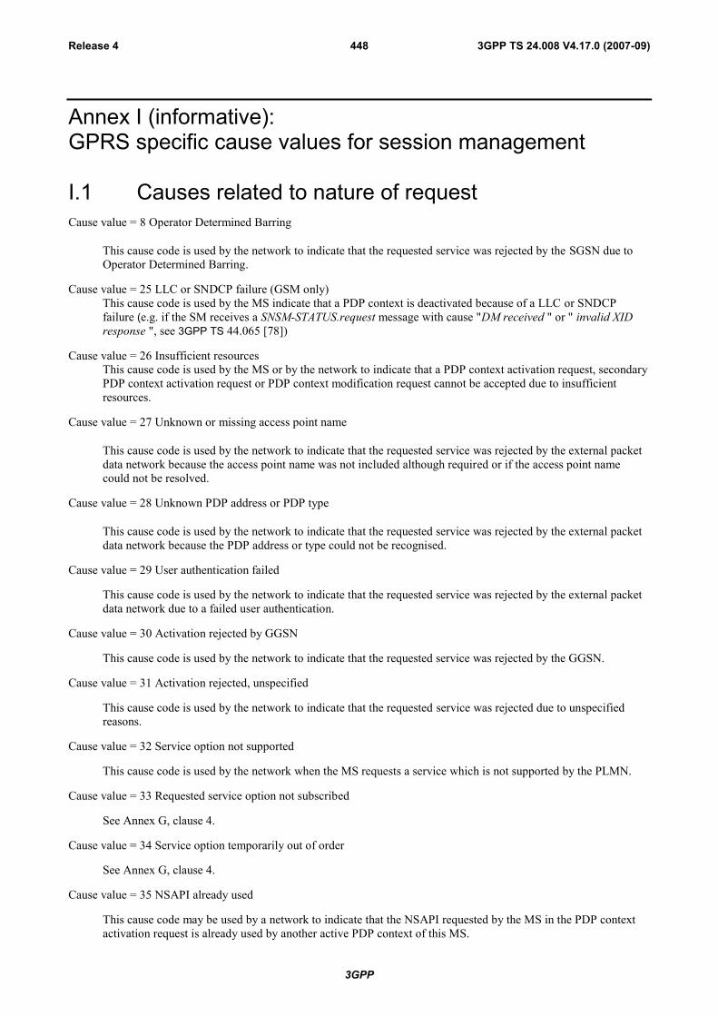
3GPP
3GPP TS 24.008 V4.17.0 (2007-09)Release 4 448
Annex I (informative):GPRS specific cause values for session management
I.1 Causes related to nature of requestCause value = 8 Operator Determined Barring
This cause code is used by the network to indicate that the requested service was rejected by the SGSN due toOperator Determined Barring.
Cause value = 25 LLC or SNDCP failure (GSM only)This cause code is used by the MS indicate that a PDP context is deactivated because of a LLC or SNDCPfailure (e.g. if the SM receives a SNSM-STATUS.request message with cause "DM received " or " invalid XIDresponse ", see 3GPP TS 44.065 [78])
Cause value = 26 Insufficient resourcesThis cause code is used by the MS or by the network to indicate that a PDP context activation request, secondaryPDP context activation request or PDP context modification request cannot be accepted due to insufficientresources.
Cause value = 27 Unknown or missing access point name
This cause code is used by the network to indicate that the requested service was rejected by the external packetdata network because the access point name was not included although required or if the access point namecould not be resolved.
Cause value = 28 Unknown PDP address or PDP type
This cause code is used by the network to indicate that the requested service was rejected by the external packetdata network because the PDP address or type could not be recognised.
Cause value = 29 User authentication failed
This cause code is used by the network to indicate that the requested service was rejected by the external packetdata network due to a failed user authentication.
Cause value = 30 Activation rejected by GGSN
This cause code is used by the network to indicate that the requested service was rejected by the GGSN.
Cause value = 31 Activation rejected, unspecified
This cause code is used by the network to indicate that the requested service was rejected due to unspecifiedreasons.
Cause value = 32 Service option not supported
This cause code is used by the network when the MS requests a service which is not supported by the PLMN.
Cause value = 33 Requested service option not subscribed
See Annex G, clause 4.
Cause value = 34 Service option temporarily out of order
See Annex G, clause 4.
Cause value = 35 NSAPI already used
This cause code may be used by a network to indicate that the NSAPI requested by the MS in the PDP contextactivation request is already used by another active PDP context of this MS.
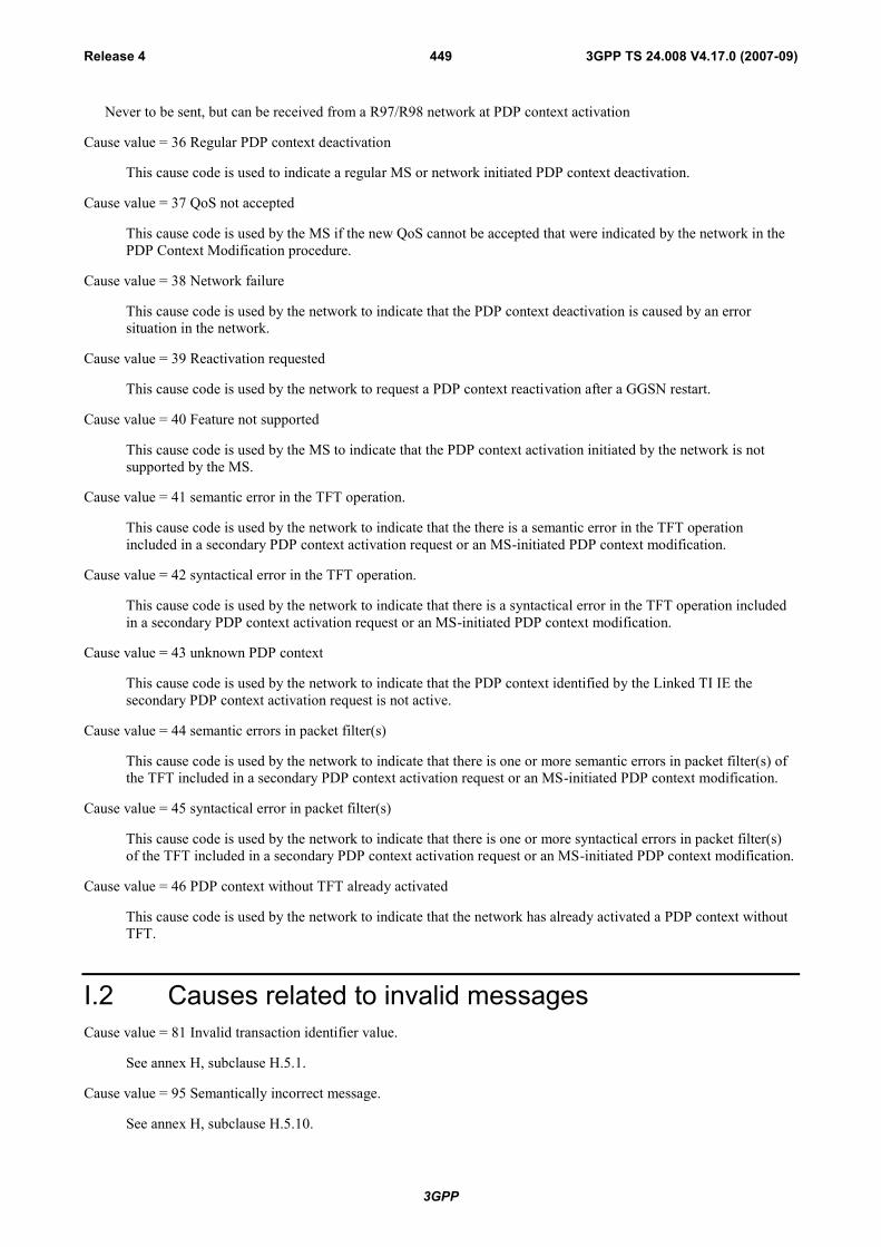
3GPP
3GPP TS 24.008 V4.17.0 (2007-09)Release 4 449
Never to be sent, but can be received from a R97/R98 network at PDP context activation
Cause value = 36 Regular PDP context deactivation
This cause code is used to indicate a regular MS or network initiated PDP context deactivation.
Cause value = 37 QoS not accepted
This cause code is used by the MS if the new QoS cannot be accepted that were indicated by the network in thePDP Context Modification procedure.
Cause value = 38 Network failure
This cause code is used by the network to indicate that the PDP context deactivation is caused by an errorsituation in the network.
Cause value = 39 Reactivation requested
This cause code is used by the network to request a PDP context reactivation after a GGSN restart.
Cause value = 40 Feature not supported
This cause code is used by the MS to indicate that the PDP context activation initiated by the network is notsupported by the MS.
Cause value = 41 semantic error in the TFT operation.
This cause code is used by the network to indicate that the there is a semantic error in the TFT operationincluded in a secondary PDP context activation request or an MS-initiated PDP context modification.
Cause value = 42 syntactical error in the TFT operation.
This cause code is used by the network to indicate that there is a syntactical error in the TFT operation includedin a secondary PDP context activation request or an MS-initiated PDP context modification.
Cause value = 43 unknown PDP context
This cause code is used by the network to indicate that the PDP context identified by the Linked TI IE thesecondary PDP context activation request is not active.
Cause value = 44 semantic errors in packet filter(s)
This cause code is used by the network to indicate that there is one or more semantic errors in packet filter(s) ofthe TFT included in a secondary PDP context activation request or an MS-initiated PDP context modification.
Cause value = 45 syntactical error in packet filter(s)
This cause code is used by the network to indicate that there is one or more syntactical errors in packet filter(s)of the TFT included in a secondary PDP context activation request or an MS-initiated PDP context modification.
Cause value = 46 PDP context without TFT already activated
This cause code is used by the network to indicate that the network has already activated a PDP context withoutTFT.
I.2 Causes related to invalid messagesCause value = 81 Invalid transaction identifier value.
See annex H, subclause H.5.1.
Cause value = 95 Semantically incorrect message.
See annex H, subclause H.5.10.
3GPP
3GPP TS 24.008 V4.17.0 (2007-09)Release 4 450
Cause value = 96 Invalid mandatory information.
See annex H, subclause H.6.1.
Cause value = 97 Message type non-existent or not implemented.
See annex H, subclause H.6.2.
Cause value = 98 Message not compatible with protocol state.
See annex H, subclause H.6.3.
Cause value = 99 Information element non-existent or not implemented.
See annex H, subclause H.6.4.
Cause value = 100 Conditional IE error.
See annex H, subclause H.6.5.
Cause value = 101 Message not compatible with protocol state.
See annex H, subclause H.6.6.
Cause value = 111 Protocol error, unspecified.
See annex H, subclause H.6.8.

3GPP
3GPP TS 24.008 V4.17.0 (2007-09)Release 4 451
Annex J (informative):Algorithm to encode frequency list information elementsSee 3GPP TS 44.018 [84].

3GPP
3GPP TS 24.008 V4.17.0 (2007-09)Release 4 452
Annex K (informative):Default Codings of Information ElementsThe information in this annex does NOT define the value of any IEI for any particular message. This annex exists to aidthe design of new messages, in particular with regard to backward compatibility with phase 1 mobile stations.
K.1 Common information elements.For the common information elements types listed below, the default coding of information element identifier bits issummarized in table K.1/3GPP TS 24.008.
Table K.1/3GPP TS 24.008: Default information element identifier codingfor common information elements
Referenceclause
8 7 6 5 4 3 2 1
1 : : : - - - - Type 1 info elements
1 1 1 1 - - - - Note 1
0 : : : : : : : Type 3 & 4 info elements
0 0 0 1 0 0 0 1 Note 10 0 0 1 0 0 1 1 Location Area Identification 10.5.1.30 0 0 1 0 1 1 1 Mobile Identity 10.5.1.40 0 0 1 1 0 0 0 Note 10 0 0 1 1 1 1 1 Note 10 0 1 0 0 0 0 0 Mobile Station classmark 3 10.5.1.7
Spare Half Octet 10.5.1.8All other values are reserved
NOTE 1: These values were allocated but never used in earlier phases of the protocol.
NOTE 2: For GPRS common information elements no default values are defined:
K.2 Radio Resource management information elements.See 3GPP TS 44.018 [84], annex K.
K.3 Mobility management information elements.For the mobility management information elements listed below, the default coding of the information elementidentifier bits is summarized in table K.3/3GPP TS 24.008.
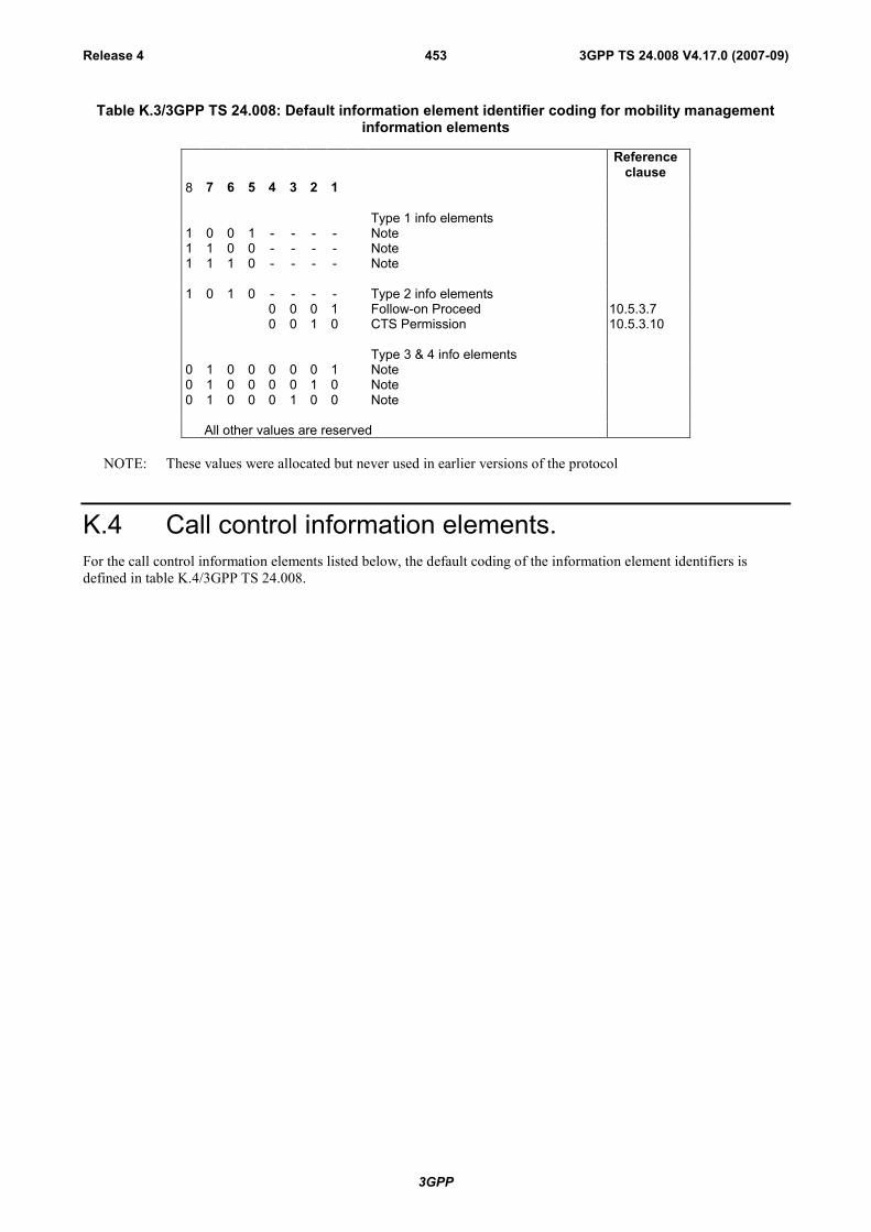
3GPP
3GPP TS 24.008 V4.17.0 (2007-09)Release 4 453
Table K.3/3GPP TS 24.008: Default information element identifier coding for mobility managementinformation elements
Referenceclause
8 7 6 5 4 3 2 1
Type 1 info elements1 0 0 1 - - - - Note1 1 0 0 - - - - Note1 1 1 0 - - - - Note
1 0 1 0 - - - - Type 2 info elements0 0 0 1 Follow-on Proceed 10.5.3.70 0 1 0 CTS Permission 10.5.3.10
Type 3 & 4 info elements0 1 0 0 0 0 0 1 Note0 1 0 0 0 0 1 0 Note0 1 0 0 0 1 0 0 Note
All other values are reserved
NOTE: These values were allocated but never used in earlier versions of the protocol
K.4 Call control information elements.For the call control information elements listed below, the default coding of the information element identifiers isdefined in table K.4/3GPP TS 24.008.

3GPP
3GPP TS 24.008 V4.17.0 (2007-09)Release 4 454
Table K.4/3GPP TS 24.008: Default information element identifier coding for call control informationelements
Referenceclause
8 7 6 5 4 3 2 11 : : : - - - - Type 1 info elements
0 0 1 - - - - shift 10.5.4.2and .3
0 1 1 - - - - Note1 0 1 - - - - Repeat indicator 10.5.4.22
1 0 1 0 : : : : Type 2 information elements0 0 0 0 More data 10.5.4.190 0 0 1 CLIR Suppression 10.5.4.11a0 0 1 0 CLIR Invocation 10.5.4.11b0 0 1 1 Reverse call setup direction 10.5.4.22a
0 : : : : : : : Type 3 & 4 info elements0 0 0 0 1 0 0 Bearer capability 10.5.4.50 0 0 1 0 0 0 Cause 10.5.4.110 0 1 0 1 0 0 Note0 0 1 0 1 0 1 Call Control Capabilities 10.5.4.5a0 0 1 1 1 0 0 Facility 10.5.4.150 0 1 1 1 1 0 Progress indicator 10.5.4.210 1 0 0 1 0 0 Auxiliary states 10.5.4.40 1 0 0 1 1 1 Note0 1 0 1 1 0 0 Keypad facility 10.5.4.170 1 1 0 1 0 0 Signal 10.5.4.231 0 0 1 1 0 0 Connected number 10.5.4.131 0 0 1 1 0 1 Connected subaddress 10.5.4.141 0 1 1 1 0 0 Calling party BCD number 10.5.4.91 0 1 1 1 0 1 Calling party subaddress 10.5.4.101 0 1 1 1 1 0 Called party BCD number 10.5.4.71 1 0 1 1 0 1 Called party subaddress 10.5.4.81 1 1 0 1 0 0 Redirecting Party BCD 10.5.4.21a1 1 1 1 1 0 1 Redirecting Party subaddress 10.5.4.21b1 1 1 1 1 0 0 Low layer compatib. 10.5.4.181 1 1 1 1 0 1 High layer compatib. 10.5.4.161 1 1 1 1 1 0 User-user 10.5.4.251 1 1 1 1 1 1 SS version indicator 10.5.4.24
NOTE: These values were allocated but never used in earlier phases of the protocol.

3GPP
3GPP TS 24.008 V4.17.0 (2007-09)Release 4 455
Annex L (normative):Establishment cause (Iu mode only)
L.1 Mapping of NAS procedure to RRC establishmentcause(Iu mode only)
When MM requests the establishment of a RR connection, the RRC establishment cause used by the MS shall beselected according to the CS NAS procedure as specified in table L.1.1.
Table L.1.1/3GPP TS 24.008: Mapping of CS NAS procedure to establishment cause
CS NAS procedure RRC Establishment cause (according 3GPP TS 25.331)Originating CS speech call Originating Conversational CallOriginating CS data call Originating Conversational CallCS Emergency call Emergency callCall re-establishment Call re-establishmentLocation update RegistrationIMSI Detach DetachMO SMS via CS domain Originating Low Priority SignallingSupplementary Services Originating High Priority SignallingAnswer to circuit switched paging Set equal to the value of the paging cause used in the reception of paging in the
RRC layerSS part of Location services Originating High Priority Signalling
When GMM requests the establishment of a PS signalling connection, the RRC establishment cause used by the MSshall be selected according to the PS NAS procedure as specified in Table L.1.2.
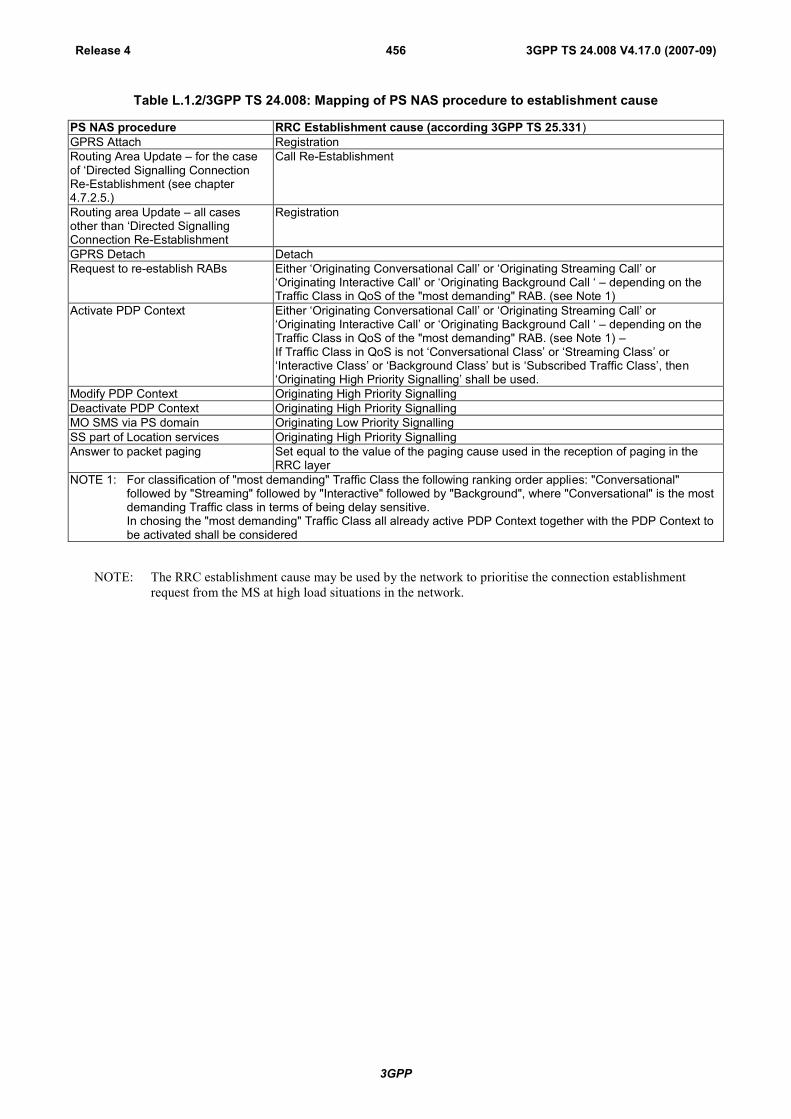
3GPP
3GPP TS 24.008 V4.17.0 (2007-09)Release 4 456
Table L.1.2/3GPP TS 24.008: Mapping of PS NAS procedure to establishment cause
PS NAS procedure RRC Establishment cause (according 3GPP TS 25.331)GPRS Attach RegistrationRouting Area Update – for the caseof ‘Directed Signalling ConnectionRe-Establishment (see chapter4.7.2.5.)
Call Re-Establishment
Routing area Update – all casesother than ‘Directed SignallingConnection Re-Establishment
Registration
GPRS Detach DetachRequest to re-establish RABs Either ‘Originating Conversational Call’ or ‘Originating Streaming Call’ or
‘Originating Interactive Call’ or ‘Originating Background Call ‘ – depending on theTraffic Class in QoS of the "most demanding" RAB. (see Note 1)
Activate PDP Context Either ‘Originating Conversational Call’ or ‘Originating Streaming Call’ or‘Originating Interactive Call’ or ‘Originating Background Call ‘ – depending on theTraffic Class in QoS of the "most demanding" RAB. (see Note 1) –If Traffic Class in QoS is not ‘Conversational Class’ or ‘Streaming Class’ or‘Interactive Class’ or ‘Background Class’ but is ‘Subscribed Traffic Class’, then‘Originating High Priority Signalling’ shall be used.
Modify PDP Context Originating High Priority SignallingDeactivate PDP Context Originating High Priority SignallingMO SMS via PS domain Originating Low Priority SignallingSS part of Location services Originating High Priority SignallingAnswer to packet paging Set equal to the value of the paging cause used in the reception of paging in the
RRC layerNOTE 1: For classification of "most demanding" Traffic Class the following ranking order applies: "Conversational"
followed by "Streaming" followed by "Interactive" followed by "Background", where "Conversational" is the mostdemanding Traffic class in terms of being delay sensitive.In chosing the "most demanding" Traffic Class all already active PDP Context together with the PDP Context tobe activated shall be considered
NOTE: The RRC establishment cause may be used by the network to prioritise the connection establishmentrequest from the MS at high load situations in the network.
3GPP
3GPP TS 24.008 V4.17.0 (2007-09)Release 4 457
Annex M (normative):Additional Requirements for backward compatibility withPCS 1900 for NA revision 0 METhis annex provides additional requirements to support network mechanisms for backward compatibility with PCS1900 for NA revision 0 mobile equipments (applicable until July 1, 1998).
PCS 1900 for NA revision 0 mobile equipments are defined to understand Mobile Network Codes made of up to 2digits. However federal regulation mandates that a 3-digit MNC shall be allocated by each administration to networkoperators. Therefore each network operator is identified by a 3-digit Mobile Country Code and a 3-digit MobileNetwork Code. An operator whose network code complies to the allocation principle specified for PCS 1900 for NAand wants to achieve for a transition period of time the backward compatibility with PCS 1900 for NA revision 0mobile equipments shall apply the following:
- The network shall send over the air interface the 3-digit Mobile Country Code and only the two most significantdigits of the Mobile Network Code (the value of the "digit" sent instead of the 3rd digit is specified in 3GPP TS24.008, subclause 10.5.1.3) (see note).
When a PCS 1900 for NA (revision greater than 0) mobile equipment recognizes over the air the Mobile Country Codeand the two most significant digits of the Mobile Network Code as being the HPLMN codes of the current IMSI, themobile equipment shall take into account the value of the sixth IMSI digit read from the SIM. If this value matches to avalue contained in the limited set of values for the least significant MNC digit assigned by the number administrationbodies for PCS 1900 for NA then the following applies for the mobile equipment:
- The value sent over the air instead of the 3rd MNC digit in the Location Area Identification (for coding see 3GPPTS 24.008, subclause 10.5.1.3) shall be interpreted as the value of the sixth IMSI digit read from the SIM.
NOTE:
It is still a network operator option to apply this requirement after July 1, 1998. However, in this case thefollowing shall be considered:
1. Network selection considerations for overlapping networks:
- Networks overlapping to the HPLMN, identified over the radio interface by an identical combinationMCC1 MCC2 MCC3 MNC1 MNC2 (possible after July 1, 1998) may be selectable by PCS 1900 forNA mobile equipments revision 0 with the same priority as the HPLMN or presented to the user as theHPLMN.
2 Roaming considerations:
- Roamers (SIM) from networks identified by an identical combination MCC1 MCC2 MCC3 MNC1MNC2 (possible after July 1, 1998) when roaming into the operator network with PCS 1900 for NAmobile equipments revision 0, may cause these equipments to exhibit an unpredictable behaviour (e.g.looping in the HPLMN selection and registration procedures).
- Home subscribers (SIM) roaming with PCS 1900 for NA mobile equipments revision 0 into networksidentified by an identical combination MCC1 MCC2 MCC3 MNC1 MNC2 (possible after July 1,1998), may consider being attached to the HPLMN.

3GPP
3GPP TS 24.008 V4.17.0 (2007-09)Release 4 458
Annex N (informative):Change RecordRelease 4 for 3GPP TS 24.008 v4.0.0 is based on 3GPP TS 24.008 version 3.5.0.
Date TSG # TSG Doc. CR Rev Subject/Comment Old New09-2000 TSG-CN-
9New release 4 for 24.008, based on V3.5.0 which was approved atthe same Plenary.
12-2000 NP-09 NP-000448 073 5 CC Enhancements for Codec Selection 3.5.0 4.0.012-2000 NP-09 NP-000447 245 3 Emergency Call Additions 3.5.0 4.0.012-2000 NP-10 NP-000667 262 1 The Group or Broadcast Call Reference from the mobile station to
the network4.0.0 4.1.0
12-2000 NP-10 NP-000669 264 1 GSM 700 addition into MS classmark & radio access capability IE 4.0.0 4.1.012-2000 NP-10 NP-000670 268 Clarification to the network initiated GPRS detach procedure (IMSI
detach)4.0.0 4.1.0
12-2000 NP-10 NP-000670 278 Correction of update status on Authentication Reject 4.0.0 4.1.012-2000 NP-10 NP-000671 283 Description Of Timer T3317 on expiry 4.0.0 4.1.012-2000 NP-10 NP-000671 286 2 Removal of "recently deactivated" condition for PDP contexts and
some references corrections4.0.0 4.1.0
12-2000 NP-10 NP-000672 290 2 The application of security procedures to emergency calls 4.0.0 4.1.012-2000 NP-10 NP-000671 295 1 Updating of Bearer Capability IE 4.0.0 4.1.012-2000 NP-10 NP-000673 301 3.1 kHz multimedia calls at 33.6 kbit/s data rate 4.0.0 4.1.012-2000 NP-10 NP-000673 303 32 kbit/s UDI/RDI multimedia 4.0.0 4.1.012-2000 NP-10 NP-000676 310 1 Change of reference to 26.103 for use of codec bitmap in the
Supported Codec List4.0.0 4.1.0
12-2000 NP-10 NP-000668 311 Introduction of EGPRS for DTM 4.0.0 4.1.012-2000 NP-10 NP-000670 312 Clarification of response handling of Service Request 4.0.0 4.1.012-2000 NP-10 NP-000670 313 Clarification of RAB re-establishment 4.0.0 4.1.012-2000 NP-10 NP-000670 314 APN used for detection of duplicated PDP context activation 4.0.0 4.1.012-2000 NP-10 NP-000670 315 1 Unsynchronized PDP contexts handling - MS less 4.0.0 4.1.012-2000 NP-10 NP-000671 317 Correction on TFT setting condition 4.0.0 4.1.012-2000 NP-10 NP-000672 318 Correction of the timer list 4.0.0 4.1.012-2000 NP-10 NP-000670 319 Correction of PDP context duplication handling 4.0.0 4.1.012-2000 NP-10 NP-000670 321 DRX parameter range correction 4.0.0 4.1.012-2000 NP-10 NP-000671 323 RR connection replaced with PS signalling connection 4.0.0 4.1.0
Jan-01 Correction of the version and date in the Header title /Page1 4.1.0 4.1.1
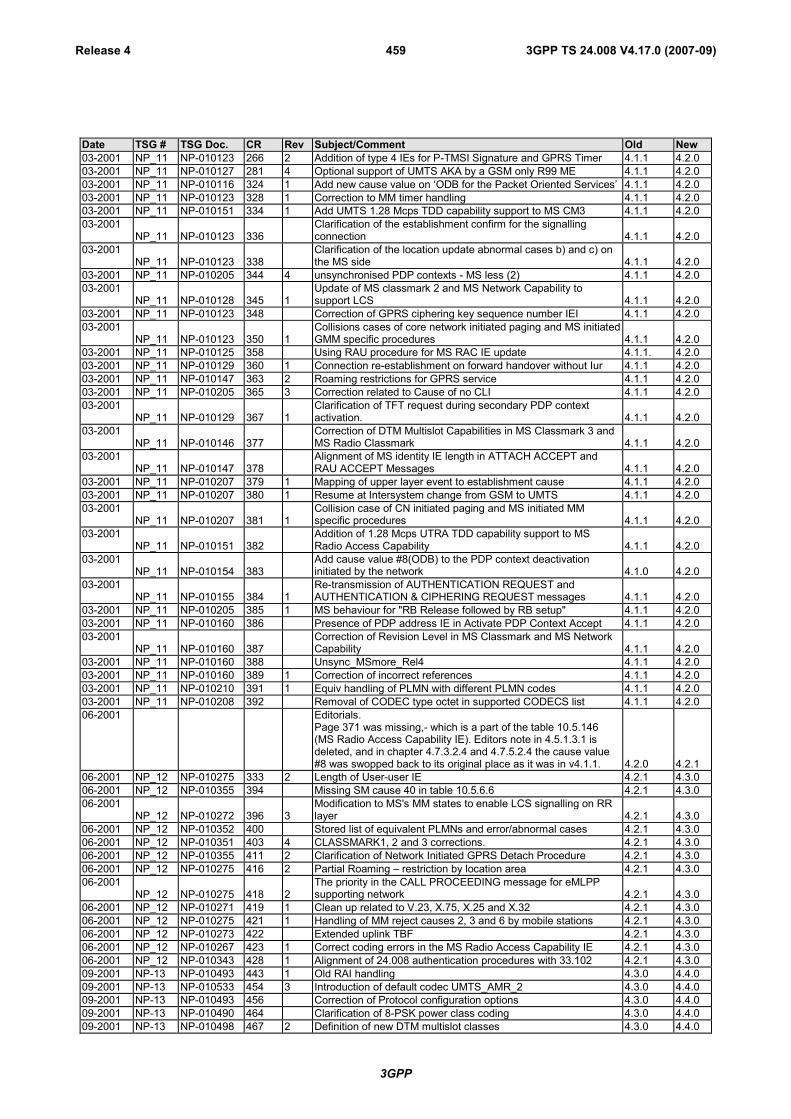
3GPP
3GPP TS 24.008 V4.17.0 (2007-09)Release 4 459
Date TSG # TSG Doc. CR Rev Subject/Comment Old New03-2001 NP_11 NP-010123 266 2 Addition of type 4 IEs for P-TMSI Signature and GPRS Timer 4.1.1 4.2.003-2001 NP_11 NP-010127 281 4 Optional support of UMTS AKA by a GSM only R99 ME 4.1.1 4.2.003-2001 NP_11 NP-010116 324 1 Add new cause value on ‘ODB for the Packet Oriented Services’ 4.1.1 4.2.003-2001 NP_11 NP-010123 328 1 Correction to MM timer handling 4.1.1 4.2.003-2001 NP_11 NP-010151 334 1 Add UMTS 1.28 Mcps TDD capability support to MS CM3 4.1.1 4.2.003-2001
NP_11 NP-010123 336Clarification of the establishment confirm for the signallingconnection 4.1.1 4.2.0
03-2001NP_11 NP-010123 338
Clarification of the location update abnormal cases b) and c) onthe MS side 4.1.1 4.2.0
03-2001 NP_11 NP-010205 344 4 unsynchronised PDP contexts - MS less (2) 4.1.1 4.2.003-2001
NP_11 NP-010128 345 1Update of MS classmark 2 and MS Network Capability tosupport LCS 4.1.1 4.2.0
03-2001 NP_11 NP-010123 348 Correction of GPRS ciphering key sequence number IEI 4.1.1 4.2.003-2001
NP_11 NP-010123 350 1Collisions cases of core network initiated paging and MS initiatedGMM specific procedures 4.1.1 4.2.0
03-2001 NP_11 NP-010125 358 Using RAU procedure for MS RAC IE update 4.1.1. 4.2.003-2001 NP_11 NP-010129 360 1 Connection re-establishment on forward handover without Iur 4.1.1 4.2.003-2001 NP_11 NP-010147 363 2 Roaming restrictions for GPRS service 4.1.1 4.2.003-2001 NP_11 NP-010205 365 3 Correction related to Cause of no CLI 4.1.1 4.2.003-2001
NP_11 NP-010129 367 1Clarification of TFT request during secondary PDP contextactivation. 4.1.1 4.2.0
03-2001NP_11 NP-010146 377
Correction of DTM Multislot Capabilities in MS Classmark 3 andMS Radio Classmark 4.1.1 4.2.0
03-2001NP_11 NP-010147 378
Alignment of MS identity IE length in ATTACH ACCEPT andRAU ACCEPT Messages 4.1.1 4.2.0
03-2001 NP_11 NP-010207 379 1 Mapping of upper layer event to establishment cause 4.1.1 4.2.003-2001 NP_11 NP-010207 380 1 Resume at Intersystem change from GSM to UMTS 4.1.1 4.2.003-2001
NP_11 NP-010207 381 1Collision case of CN initiated paging and MS initiated MMspecific procedures 4.1.1 4.2.0
03-2001NP_11 NP-010151 382
Addition of 1.28 Mcps UTRA TDD capability support to MSRadio Access Capability 4.1.1 4.2.0
03-2001NP_11 NP-010154 383
Add cause value #8(ODB) to the PDP context deactivationinitiated by the network 4.1.0 4.2.0
03-2001NP_11 NP-010155 384 1
Re-transmission of AUTHENTICATION REQUEST andAUTHENTICATION & CIPHERING REQUEST messages 4.1.1 4.2.0
03-2001 NP_11 NP-010205 385 1 MS behaviour for "RB Release followed by RB setup" 4.1.1 4.2.003-2001 NP_11 NP-010160 386 Presence of PDP address IE in Activate PDP Context Accept 4.1.1 4.2.003-2001
NP_11 NP-010160 387Correction of Revision Level in MS Classmark and MS NetworkCapability 4.1.1 4.2.0
03-2001 NP_11 NP-010160 388 Unsync_MSmore_Rel4 4.1.1 4.2.003-2001 NP_11 NP-010160 389 1 Correction of incorrect references 4.1.1 4.2.003-2001 NP_11 NP-010210 391 1 Equiv handling of PLMN with different PLMN codes 4.1.1 4.2.003-2001 NP_11 NP-010208 392 Removal of CODEC type octet in supported CODECS list 4.1.1 4.2.006-2001 Editorials.
Page 371 was missing,- which is a part of the table 10.5.146(MS Radio Access Capability IE). Editors note in 4.5.1.3.1 isdeleted, and in chapter 4.7.3.2.4 and 4.7.5.2.4 the cause value#8 was swopped back to its original place as it was in v4.1.1. 4.2.0 4.2.1
06-2001 NP_12 NP-010275 333 2 Length of User-user IE 4.2.1 4.3.006-2001 NP_12 NP-010355 394 Missing SM cause 40 in table 10.5.6.6 4.2.1 4.3.006-2001
NP_12 NP-010272 396 3Modification to MS's MM states to enable LCS signalling on RRlayer 4.2.1 4.3.0
06-2001 NP_12 NP-010352 400 Stored list of equivalent PLMNs and error/abnormal cases 4.2.1 4.3.006-2001 NP_12 NP-010351 403 4 CLASSMARK1, 2 and 3 corrections. 4.2.1 4.3.006-2001 NP_12 NP-010355 411 2 Clarification of Network Initiated GPRS Detach Procedure 4.2.1 4.3.006-2001 NP_12 NP-010275 416 2 Partial Roaming – restriction by location area 4.2.1 4.3.006-2001
NP_12 NP-010275 418 2The priority in the CALL PROCEEDING message for eMLPPsupporting network 4.2.1 4.3.0
06-2001 NP_12 NP-010271 419 1 Clean up related to V.23, X.75, X.25 and X.32 4.2.1 4.3.006-2001 NP_12 NP-010275 421 1 Handling of MM reject causes 2, 3 and 6 by mobile stations 4.2.1 4.3.006-2001 NP_12 NP-010273 422 Extended uplink TBF 4.2.1 4.3.006-2001 NP_12 NP-010267 423 1 Correct coding errors in the MS Radio Access Capability IE 4.2.1 4.3.006-2001 NP_12 NP-010343 428 1 Alignment of 24.008 authentication procedures with 33.102 4.2.1 4.3.009-2001 NP-13 NP-010493 443 1 Old RAI handling 4.3.0 4.4.009-2001 NP-13 NP-010533 454 3 Introduction of default codec UMTS_AMR_2 4.3.0 4.4.009-2001 NP-13 NP-010493 456 Correction of Protocol configuration options 4.3.0 4.4.009-2001 NP-13 NP-010490 464 Clarification of 8-PSK power class coding 4.3.0 4.4.009-2001 NP-13 NP-010498 467 2 Definition of new DTM multislot classes 4.3.0 4.4.0
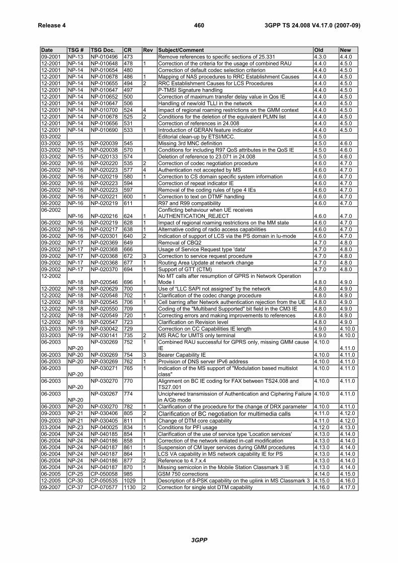
3GPP
3GPP TS 24.008 V4.17.0 (2007-09)Release 4 460
Date TSG # TSG Doc. CR Rev Subject/Comment Old New09-2001 NP-13 NP-010496 473 Remove references to specific sections of 25.331 4.3.0 4.4.012-2001 NP-14 NP-010648 478 1 Correction of the criteria for the usage of combined RAU 4.4.0 4.5.012-2001 NP-14 NP-010654 480 Correction of default codec selection criterion 4.4.0 4.5.012-2001 NP-14 NP-010678 486 1 Mapping of NAS procedures to RRC Establishment Causes 4.4.0 4.5.012-2001 NP-14 NP-010655 494 2 RRC Establishment Causes for LCS Procedures 4.4.0 4.5.012-2001 NP-14 NP-010647 497 P-TMSI Signature handling 4.4.0 4.5.012-2001 NP-14 NP-010652 500 Correction of maximum transfer delay value in Qos IE 4.4.0 4.5.012-2001 NP-14 NP-010647 506 Handling of new/old TLLI in the network 4.4.0 4.5.012-2001 NP-14 NP-010700 524 4 Impact of regional roaming restrictions on the GMM context 4.4.0 4.5.012-2001 NP-14 NP-010678 525 2 Conditions for the deletion of the equivalent PLMN list 4.4.0 4.5.012-2001 NP-14 NP-010656 531 Correction of references in 24.008 4.4.0 4.5.012-2001 NP-14 NP-010690 533 1 Introduction of GERAN feature indicator 4.4.0 4.5.003-2002 Editorial clean-up by ETSI/MCC. 4.5.003-2002 NP-15 NP-020039 545 Missing 3rd MNC definition 4.5.0 4.6.003-2002 NP-15 NP-020038 570 1 Conditions for including R97 QoS attributes in the QoS IE 4.5.0 4.6.003-2002 NP-15 NP-020133 574 Deletion of reference to 23.071 in 24.008 4.5.0 4.6.006-2002 NP-16 NP-020220 535 2 Correction of codec negotiation procedure 4.6.0 4.7.006-2002 NP-16 NP-020223 577 4 Authentication not accepted by MS 4.6.0 4.7.006-2002 NP-16 NP-020219 580 1 Correction to CS domain specific system information 4.6.0 4.7.006-2002 NP-16 NP-020223 594 Correction of repeat indicator IE 4.6.0 4.7.006-2002 NP-16 NP-020223 597 Removal of the coding rules of type 4 IEs 4.6.0 4.7.006-2002 NP-16 NP-020221 600 1 Correction to text on DTMF handling 4.6.0 4.7.006-2002 NP-16 NP-020219 611 R97 and R99 compatibility 4.6.0 4.7.006-2002
NP-16 NP-020216 624 1Conflicting behaviour when UE receivesAUTHENTICATION_REJECT 4.6.0 4.7.0
06-2002 NP-16 NP-020219 628 1 Impact of regional roaming restrictions on the MM state 4.6.0 4.7.006-2002 NP-16 NP-020217 638 1 Alternative coding of radio access capabilities 4.6.0 4.7.006-2002 NP-16 NP-020301 640 2 Indication of support of LCS via the PS domain in Iu-mode 4.6.0 4.7.009-2002 NP-17 NP-020369 649 Removal of CBQ2 4.7.0 4.8.009-2002 NP-17 NP-020368 666 Usage of Service Request type 'data' 4.7.0 4.8.009-2002 NP-17 NP-020368 672 3 Correction to service request procedure 4.7.0 4.8.009-2002 NP-17 NP-020368 677 1 Routing Area Update at network change 4.7.0 4.8.009-2002 NP-17 NP-020370 694 1 Support of GTT (CTM) 4.7.0 4.8.012-2002
NP-18 NP-020546 696 1No MT calls after resumption of GPRS in Network OperationMode I 4.8.0 4.9.0
12-2002 NP-18 NP-020629 700 Use of “LLC SAPI not assigned” by the network 4.8.0 4.9.012-2002 NP-18 NP-020548 702 1 Clarification of the codec change procedure 4.8.0 4.9.012-2002 NP-18 NP-020545 706 1 Cell barring after Network authentication rejection from the UE 4.8.0 4.9.012-2002 NP-18 NP-020550 709 Coding of the "Multiband Supported" bit field in the CM3 IE 4.8.0 4.9.012-2002 NP-18 NP-020549 720 1 Correcting errors and making improvements to references 4.8.0 4.9.012-2002 NP-18 NP-020547 723 Clarification on Revision level 4.8.0 4.9.003-2003 NP-19 NP-030042 729 Correction on CC Capabilities IE length 4.9.0 4.10.003-2003 NP-19 NP-030141 735 2 MS RAC for UMTS only terminal 4.9.0 4.10.006-2003
NP-20NP-030269 752 1 Combined RAU successful for GPRS only, missing GMM cause
IE4.10.0
4.11.006-2003 NP-20 NP-030269 754 3 Bearer Capability IE 4.10.0 4.11.006-2003 NP-20 NP-030269 762 1 Provision of DNS server IPv6 address 4.10.0 4.11.006-2003
NP-20NP-030271 765 1 Indication of the MS support of "Modulation based multislot
class"4.10.0 4.11.0
06-2003NP-20
NP-030270 770 Alignment on BC IE coding for FAX between TS24.008 andTS27.001
4.10.0 4.11.0
06-2003NP-20
NP-030267 774 Unciphered transmission of Authentication and Ciphering Failurein A/Gb mode
4.10.0 4.11.0
06-2003 NP-20 NP-030270 782 1 Clarification of the procedure for the change of DRX parameter 4.10.0 4.11.009-2003 NP-21 NP-030406 805 2 Clarification of BC negotiation for multimedia calls 4.11.0 4.12.009-2003 NP-21 NP-030405 811 1 Change of DTM core capability 4.11.0 4.12.003-2004 NP-23 NP-040025 834 1 Conditions for PFI usage 4.12.0 4.13.006-2004 NP-24 NP-040185 854 1 Clarification of the use of service type 'Location services' 4.13.0 4.14.006-2004 NP-24 NP-040186 858 1 Correction of the network initiated in-call modification 4.13.0 4.14.006-2004 NP-24 NP-040187 861 1 Suspension of CM layer services during GMM procedures 4.13.0 4.14.006-2004 NP-24 NP-040187 864 1 LCS VA capability in MS network capability IE for PS 4.13.0 4.14.006-2004 NP-24 NP-040186 877 2 Reference to 4.7.x.4 4.13.0 4.14.006-2004 NP-24 NP-040187 870 1 Missing semicolon in the Mobile Station Classmark 3 IE 4.13.0 4.14.006-2005 CP-25 CP-050058 985 GSM 750 corrections 4.14.0 4.15.012-2005 CP-30 CP-050535 1029 1 Description of 8-PSK capability on the uplink in MS Classmark 3 4.15.0 4.16.009-2007 CP-37 CP-070577 1130 2 Correction for single slot DTM capability 4.16.0 4.17.0