

Multi-RAT Small Cells: An Efficient Solution for 3G/LTE Deployment
Upload
truongdangCategory
view
231download
3
3G Wireless Remote Site Deployment Guide
February 2012 Series

PrefaceFebruary 2012 Series
Preface
Who Should Read This GuideThis Cisco® Smart Business Architecture (SBA) guide is for people who fill a variety of roles:
• Systems engineers who need standard procedures for implementing solutions
• Project managers who create statements of work for Cisco SBA implementations
• Sales partners who sell new technology or who create implementation documentation
• Trainers who need material for classroom instruction or on-the-job training
In general, you can also use Cisco SBA guides to improve consistency among engineers and deployments, as well as to improve scoping and costing of deployment jobs.
Release SeriesCisco strives to update and enhance SBA guides on a regular basis. As we develop a new series of SBA guides, we test them together, as a complete system. To ensure the mutual compatibility of designs in Cisco SBA guides, you should use guides that belong to the same series.
All Cisco SBA guides include the series name on the cover and at the bottom left of each page. We name the series for the month and year that we release them, as follows:
month year Series
For example, the series of guides that we released in August 2011 are the “August 2011 Series”.
You can find the most recent series of SBA guides at the following sites:
Customer access: http://www.cisco.com/go/sba
Partner access: http://www.cisco.com/go/sbachannel
How to Read CommandsMany Cisco SBA guides provide specific details about how to configure Cisco network devices that run Cisco IOS, Cisco NX-OS, or other operating systems that you configure at a command-line interface (CLI). This section describes the conventions used to specify commands that you must enter.
Commands to enter at a CLI appear as follows:
configure terminal
Commands that specify a value for a variable appear as follows:
ntp server 10.10.48.17
Commands with variables that you must define appear as follows:
class-map [highest class name]
Commands shown in an interactive example, such as a script or when the command prompt is included, appear as follows:
Router# enable
Long commands that line wrap are underlined. Enter them as one command:
wrr-queue random-detect max-threshold 1 100 100 100 100 100 100 100 100
Noteworthy parts of system output or device configuration files appear highlighted, as follows:
interface Vlan64 ip address 10.5.204.5 255.255.255.0
Comments and QuestionsIf you would like to comment on a guide or ask questions, please use the forum at the bottom of one of the following sites:
Customer access: http://www.cisco.com/go/sba
Partner access: http://www.cisco.com/go/sbachannel
An RSS feed is available if you would like to be notified when new comments are posted.

Table of ContentsFebruary 2012 Series
What’s In This SBA Guide . . . . . . . . . . . . . . . . . . . . . . . . . . . . . . . . . . . . . . . . . . . . . . . . . .1
About SBA . . . . . . . . . . . . . . . . . . . . . . . . . . . . . . . . . . . . . . . . . . . . . . . . . . . . . . . . . . . . . . 1
About This Guide . . . . . . . . . . . . . . . . . . . . . . . . . . . . . . . . . . . . . . . . . . . . . . . . . . . . . . . 1
Business Overview . . . . . . . . . . . . . . . . . . . . . . . . . . . . . . . . . . . . . . . . . . . . . . . . . . . . . . . .2
The Case for Wireless . . . . . . . . . . . . . . . . . . . . . . . . . . . . . . . . . . . . . . . . . . . . . . . . . . 2
Technology Overview . . . . . . . . . . . . . . . . . . . . . . . . . . . . . . . . . . . . . . . . . . . . . . . . . . . . .3
Cellular Options . . . . . . . . . . . . . . . . . . . . . . . . . . . . . . . . . . . . . . . . . . . . . . . . . . . . . . . . . 3
Deployment Details . . . . . . . . . . . . . . . . . . . . . . . . . . . . . . . . . . . . . . . . . . . . . . . . . . . . . . . .4
Deploying a VPN Headend Router with VTI . . . . . . . . . . . . . . . . . . . . . . . . . . . . . 5
Configuring a GSM-Specific Remote-Site Router . . . . . . . . . . . . . . . . . . . . . . . 8
Configuring a CDMA-Specific Remote-Site Router . . . . . . . . . . . . . . . . . . . . . 9
Configuring a Remote-Site 3G Router . . . . . . . . . . . . . . . . . . . . . . . . . . . . . . . . . 10
Controlling Usage of the 3G Interface . . . . . . . . . . . . . . . . . . . . . . . . . . . . . . . . . . 15
Appendix A: Product Part Numbers . . . . . . . . . . . . . . . . . . . . . . . . . . . . . . . . . . . . . .17
Appendix B: Branch ISR Configuration for GSM . . . . . . . . . . . . . . . . . . . . . . . . . .18
Appendix C: Branch ISR Configuration for CDMA . . . . . . . . . . . . . . . . . . . . . . . . .21
Appendix D: Headend or Headquarters ISR Configuration . . . . . . . . . . . . . . .24
Table of Contents
ALL DESIGNS, SPECIFICATIONS, STATEMENTS, INFORMATION, AND RECOMMENDATIONS (COLLECTIVELY, “DESIGNS”) IN THIS MANUAL ARE PRESENTED “AS IS,” WITH ALL FAULTS. CISCO AND ITS SUPPLIERS DISCLAIM ALL WARRANTIES, INCLUDING, WITHOUT LIMITATION, THE WARRANTY OF MERCHANTABILITY, FITNESS FOR A PARTICULAR PURPOSE AND NONINFRINGEMENT OR ARISING FROM A COURSE OF DEALING, USAGE, OR TRADE PRACTICE. IN NO EVENT SHALL CISCO OR ITS SUPPLIERS BE LIABLE FOR ANY INDIRECT, SPECIAL, CONSEQUENTIAL, OR INCIDENTAL DAMAGES, INCLUDING, WITHOUT LIMITA- TION, LOST PROFITS OR LOSS OR DAMAGE TO DATA ARISING OUT OF THE USE OR INABILITY TO USE THE DESIGNS, EVEN IF CISCO OR ITS SUPPLIERS HAVE BEEN ADVISED OF THE POSSIBILITY OF SUCH DAMAGES. THE DESIGNS ARE SUBJECT TO CHANGE WITHOUT NOTICE. USERS ARE SOLELY RESPONSIBLE FOR THEIR APPLICATION OF THE DESIGNS. THE DESIGNS DO NOT CONSTITUTE THE TECHNICAL OR OTHER PROFESSIONAL ADVICE OF CISCO, ITS SUPPLIERS OR PARTNERS. USERS SHOULD CONSULT THEIR OWN TECHNICAL ADVISORS BEFORE IMPLEMENTING THE DESIGNS. RESULTS MAY VARY DEPENDING ON FACTORS NOT TESTED BY CISCO.
Any Internet Protocol (IP) addresses used in this document are not intended to be actual addresses. Any examples, command display output, and figures included in the document are shown for illustrative purposes only. Any use of actual IP addresses in illustrative content is unintentional and coincidental.
© 2012 Cisco Systems, Inc. All rights reserved.

What’s In This SBA Guide
About SBACisco SBA helps you design and quickly deploy a full-service business network. A Cisco SBA deployment is prescriptive, out-of-the-box, scalable, and flexible.
Cisco SBA incorporates LAN, WAN, wireless, security, data center, application optimization, and unified communication technologies—tested together as a complete system. This component-level approach simplifies system integration of multiple technologies, allowing you to select solutions that solve your organization’s problems—without worrying about the technical complexity.
For more information, see the How to Get Started with Cisco SBA document:
http://www.cisco.com/en/US/docs/solutions/Enterprise/Borderless_Networks/Smart_Business_Architecture/SBA_Getting_Started.pdf
About This GuideThis additional deployment guide includes the following sections:
• BusinessOverview—The challenge that your organization faces. Business decision makers can use this section to understand the rel-evance of the solution to their organizations’ operations.
• TechnologyOverview—How Cisco solves the challenge. Technical decision makers can use this section to understand how the solution works.
• DeploymentDetails—Step-by-step instructions for implementing the solution. Systems engineers can use this section to get the solution up and running quickly and reliably.
This guide presumes that you have read the prerequisites guides, as shown on the Route to Success below.
1What’s In This SBA GuideFebruary 2012 Series
Route to SuccessTo ensure your success when implementing the designs in this guide, you should read any guides that this guide depends upon—shown to the left of this guide on the route above. Any guides that depend upon this guide are shown to the right of this guide.
For customer access to all SBA guides: http://www.cisco.com/go/sba For partner access: http://www.cisco.com/go/sbachannel
FoundationDesign Overview
FoundationDeployment Guide
3G Wireless Remote SiteDeployment Guide
BN
You are HerePrerequisite Guides

2Business OverviewFebruary 2012 Series
Business Overview
The Case for WirelessConnectivity to the organization’s data is no longer confined to the walls of the building. The world is more mobile, and today’s consumers expect products and services to come to them. For example:
• Mobile clinics require up-to-the-minute communication with various specialists and the ability to exchange patient x-rays, medical tests, and files.
• Emergency Mobile Deployment Units require up-to-the-minute communication, remote information feedback, and local site intercommunication.
• Tradeshows and special events require interactive kiosks and Internet hotspots, credit card processing, and up-to-the-minute marketing campaigns through digital advertising.
Figure 1 - Use cases
Cellular connectivity is a resilient solution for your remote site. A resilient solution provides an always-accessible network for the applications that users interact with directly, from site-to-site backup and recovery to reading email. How well users interact with the network, and their ability to reach essential services, impacts the organization’s overall performance.
Reliable network services provided by Cisco Smart Business Architecture (SBA)—such as the Internet connection, WAN infrastructure, and secu-rity—help ensure that an organization can rely on applications such as web conferencing for critical collaboration.
High availability at the remote site is an essential requirement for productiv-ity, safety, and security within the majority of organizations. Therefore, the ability to maintain connectivity for critical business data transactions is imperative to the Cisco SBA for Midsize Organizations design.
Cisco SBA for Midsize Organizations is a prescriptive architecture that delivers an easy-to-use, flexible, and scalable network with wired, wire-less, security, WAN optimization, and unified communication components. It eliminates the challenges of integrating various network components by using a standardized design that is reliable and has comprehensive support offerings.
To learn more about Cisco SBA, visit:
http://www.cisco.com/go/sba or http://www.cisco.com/go/partner/smartarchitecture
Reader Tip

3Technology OverviewFebruary 2012 Series
Technology Overview
Cellular OptionsA solution with cellular connectivity provides flexible, high-speed, high-bandwidth. There are two competing technologies that provide high-bandwidth network WAN connectivity where cellular service is avail-able: Code Division Multiple Access (CDMA) or Global System for Mobile Communications (GSM). Much of the world can only select one or the other.
CDMA
CDMA has its roots in World War II. It only relates to over-the-air transmis-sion, giving each user the full use of the radio spectrum, which can provide higher data rates than can be achieved with GSM, which leverages Time-Division Multiple Access (TDMA) and General Packet Radio Service (GPRS), a packetized technology. CDMA uses a much stronger signal and can have a much better coverage model, sometimes at the expense of GSM when both technologies exist together in densely populated areas.
When choosing CDMA over GSM, consider where you are deploying your remote site. CDMA is predominately used within the United States, but it is used rarely elsewhere in the world and is nonexistent in Europe because the European Union mandates the sole use of GSM.
GSM
GSM was invented in 1987 by the GSM Association, an international organi-zation dedicated to developing the GSM standard worldwide. The data rates are typically slower than those that can be achieved with CDMA; however, with enhanced data rates for GSM evolution (EDGE), the performance dis-parity is getting smaller. GSM also offers the advantage of being the world leader in deployment, with over 74 percent of the cellular deployments using GSM. As already mentioned, it is used by virtually all of Europe. Another clear advantage of GSM over CDMA is the ability to move the Subscriber Identity Module (SIM) from one device to another, which essentially moves your service from device to device without your having to work through your service provider.
3G and 4G
Today’s working data standard is third generation (3G), which theoretically can achieve data rates up to 14 Mbps. Some carriers are beginning to offer the latest fourth generation (4G) standard, which promises up to Gigabit per second (Gbps) data rates and must be able to at least achieve 100 Mbps data rates. Both of these standards are defined by the International Telecommunication Union (ITU).
According to the ITU requirements, a 4G cellular system must have target peak data rates of up to approximately 100 Mbps for high mobility such as mobile access and up to approximately 1 Gbps for low mobility such as nomadic/local wireless access. The promise of these data rates and band-width brings interesting opportunities to the remote branch offices.
4Deployment DetailsFebruary 2012 Series
Deployment Details
Before you begin the deployment process, you need to determine which technology to leverage and define your physical topology.
In order to decide which technology to use, consider the following questions:
• What technology is supported in the region where this remote site will be located?
Contact your local service provider to see what is in your area. As an example, Europe has mandated GSM for all cellular.
• Do you want or require redundant hardware for hot swap, should a failure occur?
GSM allows you to move your SIM card from device to device without your having to work through your service provider.
• Is high data throughput a requirement?
Although the difference in data throughput for each technology is closing, CDMA is still the clear leader.
• Will your office move from region to region?
If your remote site has wheels and moves around, such as a health clinic, you may wish to include both CDMA and GSM within your solu-tion, so that you can choose the best technology for your site.
• If price of service or service provider offerings are factors, which will provide the best features for the price for your remote site?
Some service providers offer both a business and wireless service to provide an alternative connection away from the public network (Internet) and drop you on your private Multiprotocol Label Switching (MPLS) network.
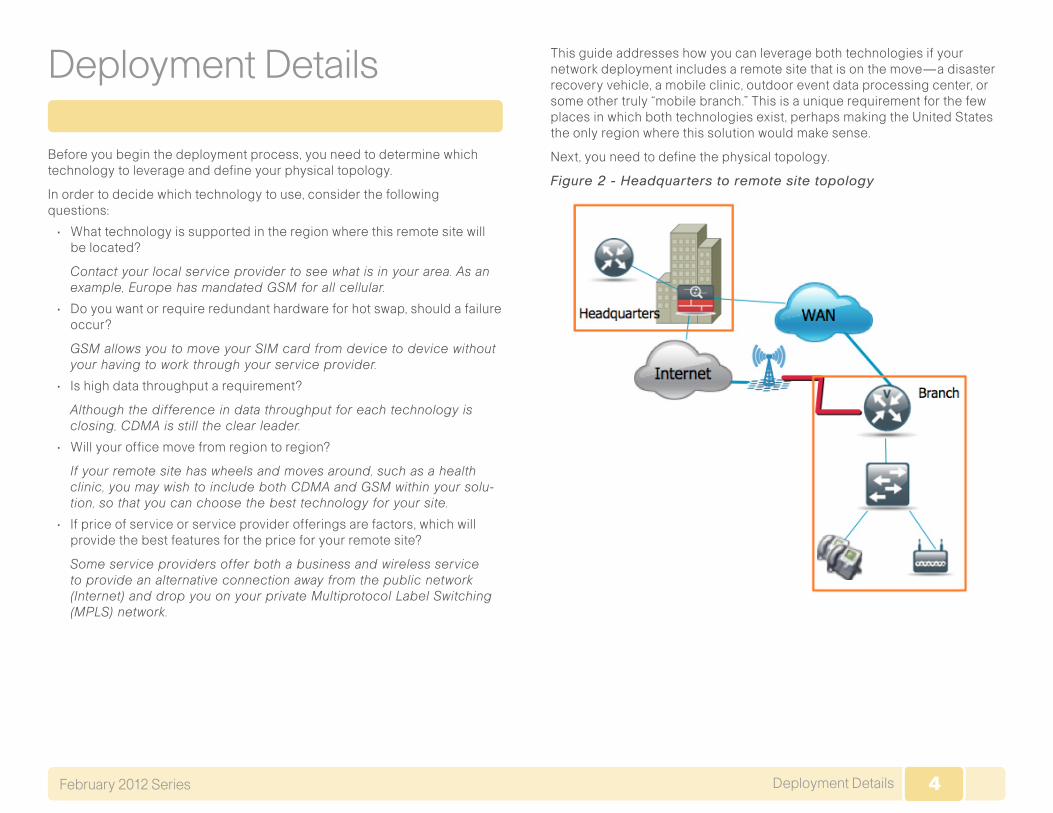
This guide addresses how you can leverage both technologies if your network deployment includes a remote site that is on the move—a disaster recovery vehicle, a mobile clinic, outdoor event data processing center, or some other truly “mobile branch.” This is a unique requirement for the few places in which both technologies exist, perhaps making the United States the only region where this solution would make sense.
Next, you need to define the physical topology.
Figure 2 - Headquarters to remote site topology

5Deployment DetailsFebruary 2012 Series
The Headquarters topology in Figure 3 shows the Internet edge firewall passing VPN traffic through to the Integrated Services Router (ISR) that serves as the VPN headend router within Cisco SBA.
Figure 3 - Headquarters topologyDeploying a VPN Headend Router with VTI
1. Configure ISAKMP, IPsec on the headend
2. Configure VTI template on the headend
3. Configure the headquarters ASA
Process
Follow these procedures to configure remote-site IPsec peers to connect to the VPN headend router. The design applies Cisco IOS IPsec Virtual Tunnel Interface (VTI) to provide encrypted transport of data and voice information with minimal configuration burden and maximum functionality. VTI offers two modes of operation:
• Static—Static VTI can initiate tunnels to other static VTI sites.
• Dynamic—Multiple static VTI sites can initiate tunnels to a template-based dynamic VTI (DVTI) aggregation point that offers simple configuration.
VTI was selected because:
• DVTI does not require that you know the remote sites’ public address, which simplifies configuration for remote sites that may be assigned an address dynamically or are using Network Address Translation (NAT).
• DVTI requires just one tunnel configuration for the headend router, offer-ing the least complex configuration and troubleshooting.
• VTI offers a virtual interface for applications of quality of service (QoS) policies, NAT, firewall, intrusion prevention IPS, access lists (ACLs), and tunnel monitoring, as compared to traditional crypto-map VPN configuration.
• VTI configuration provides superior dynamic routing flexibility to enable the requirements of the Cisco SBA design.
• Remote sites initiate their connection to the DVTI responder on the headend router, which will create a virtual tunnel interface for every remote site’s connection. DVTI applies a template-based configuration for remote sites’ connectivity so that multiple tunnels may be created by using one DVTI configuration. You don’t need to do any additional configuration to support multiple remote sites.

6Deployment DetailsFebruary 2012 Series
Usually, when you add WAN resilience to your remote-site router, you will have already configured the headend or headquarters router, or other termination point. However, this document assumes that this is your first resilient remote-site configuration in which you are leveraging the public network.
Tech Tip
Procedure 1 Configure ISAKMP, IPsec on the headend
Step 1: Configure the pre-shared key.
The crypto keyring defines a pre-shared key (or password) valid for an IP peer. If it applies to any IP source, this key is a wildcard pre-shared key. You configure a wildcard key by using the 0.0.0.0 0.0.0.0 network/mask combination.
crypto keyring [keyring name] pre-shared-key address 0.0.0.0 0.0.0.0 key [pre-shared key]
Step 2: Configure the Internet Security Association and Key Management Protocol (ISAKMP) policy.
The ISAKMP policy for VTI uses the following:
• Advanced Encryption Standard (AES) with a 128-bit key
• Secure Hash Standard (SHA)
• Authentication by pre-shared key
• Diffie-Hellman group 2
crypto isakmp policy [policy sequence] encr aes hash sha authentication pre-share group 2
Step 3: Create the ISAKMP profile.
The ISAKMP profile creates an association between an identity address, a VTI virtual template, and a crypto keyring. A wildcard identity address is referenced by using 0.0.0.0.
crypto isakmp profile [ISAKMP profile name] keyring [keyring name] match identity address 0.0.0.0 virtual-template [VTI template number]
Step 4: Define the IPsec transform set.
A transform set is an acceptable combination of security protocols, algo-rithms, and other settings to apply to IPsec-protected traffic. Peers agree to use a particular transform set when they protect a particular data flow.
The IPsec transform set uses the following:
• Encapsulating Security Payload (ESP) with the 128-bit AES encryption algorithm
• ESP with the SHA (Hash-based Message Authentication Code [HMAC] variant) authentication algorithm
crypto ipsec transform-set [IPSec transform-set name] esp-aes esp-sha-hmac
Step 5: Create the IPsec profile.
The IPsec profile creates an association between an identity address and an IPsec transform set.
crypto ipsec profile [IPSec profile name] set transform-set [IPSec transform-set name]
Example
crypto keyring sba-keys pre-shared-key address 0.0.0.0 0.0.0.0 key sbacrypto isakmp policy 1 encr aes hash sha authentication pre-share group 2crypto isakmp profile sba-isakmp keyring sba-keys

7Deployment DetailsFebruary 2012 Series
match identity address 0.0.0.0 virtual-template 1crypto ipsec transform-set sba-xform esp-aes esp-sha-hmac crypto ipsec profile sba-ipsec set transform-set sba-xform
Procedure 2 Configure VTI template on the headend
Step 1: Configure basic interface settings.
interface Virtual-Template [VTI template number] type tunnel ip unnumbered Loopback0
Step 2: Configure the tunnel template.
The tunnel source is the interface that connects the VTI headend router to the core switch.
interface Virtual-Template [VTI template number] type tunnel tunnel source [source interface] tunnel mode ipsec ipv4 tunnel protection ipsec profile [IPsec profile name]
When applying the virtual-template configuration, be sure that you apply the typetunnel option. Without this option, the VTI template will not apply to the cryptographic configuration.
Tech Tip
ExampleforStep2
interface Virtual-Template1 type tunnel ip unnumbered Loopback0 tunnel source Port-channel32 tunnel mode ipsec ipv4 tunnel protection ipsec profile sba-ipsec
Step 3: Configure Enhanced Interior Gateway Routing Protocol (EIGRP) interface timers.
EIGRP is already configured on the VPN headend router, but in this step you configure some additional EIGRP requirements for the VTI tunnel interface.
The EIGRP hello interval is increased to 20 seconds and the EIGRP hold time is increased to 60 seconds to accommodate the variable delay and latency associated with data running over a 3G network.
interface Virtual-Template [VTI template number] type tunnel ip hello-interval eigrp [as number] [hello-interval (sec)] ip hold-time eigrp [as number] [hold-time (sec)]
ExampleforStep3
interface Virtual-Template1 type tunnel ip hello-interval eigrp 1 20 ip hold-time eigrp 1 60
Procedure 3 Configure the headquarters ASA
The VPN hub is connected to the network core, behind the Internet edge firewall. The Internet Edge Adaptive Security Appliance (ASA) must forward all incoming VPN traffic to the router’s private IP address and accommodate the VPN traffic in the ASA’s outside-to-inside access policy.
Step 1: Apply the following configuration on the active Internet Edge ASA, to enable connectivity to the VPN headend router by translating the outside address of 172.16.20.7 to the VPN headend router’s private address, 10.10.32.126. This configuration allows VPN traffic to traverse the ASA and connect to the headend VTI hub router.
object network VPN-hub-inside host 10.10.32.126 description Private Address for WAN Router/VPN Hubobject network VPN-hub-outside host 172.16.20.7 description Public IP Address for VPN Hub!object-group service isakmp-esp service-object udp destination eq 4500 service-object udp destination eq isakmp service-object esp!

8Deployment DetailsFebruary 2012 Series
access-list outside_access_in extended permit object-group isakmp-esp any object VPN-hub-inside!nat (inside,outside) after-auto source static VPN-hub-inside VPN-hub-outside!access-group outside_access_in in interface outside
Configuring a GSM-Specific Remote-Site Router
1. Install the GSM HWIC into the ISR
2. Configure the chat script and GSM profile
Process
You must get a data service account from your service provider. You will receive a SIM card that you install on the GSM high-speed WAN interface card (HWIC). You will also receive the following information: PPP Challenge-Handshake Authentication Protocol (CHAP) User-Name (hostname), PPP CHAP Password, and APN (Access Point Name).
Tech Tip
Procedure 1 Install the GSM HWIC into the ISR
Figure 4 - GSM HWIC SIM card installation
Step 1: Insert the SIM card into the HWIC.
Step 2: Power off the ISR G2 router.
Step 3: Insert and fasten the GSM HWIC into the router.
Step 4: Power on the router and begin configuration.
Procedure 2 Configure the chat script and GSM profile
Chat scripts are strings of text used to send commands for modem dialing, to log in to remote systems, and to initialize asynchronous devices that are connected to an asynchronous line. The 3G WAN interface should be treated just like any other asynchronous interface.
The following chat script shows the required information to connect to the AT&T GSM network.

9Deployment DetailsFebruary 2012 Series
Step 1: This chat script uses a carrier-specific dial string and a timeout value of 30 seconds. Note that your carrier may require a different chat script.
chat-script [Script-Name] [Script]
ExampleforStep1
chat-script GSM “” “atdt*98*1#” TIMEOUT 30 “CONNECT”
Step 2: Apply the chat-script to the asynchronous line.
line [Cellular-Interface-Number] script dialer [Script-Name]
ExampleforStep2
For the interface cellular0/0/0, the matching line number would be:
line 0/0/0 script dialer GSM
Step 3: Create the GSM profile.
This step should be completed from enable mode and not from configura-tion mode.
cellular [Cellular-Interface] gsm profile create [sequence-Number] [AP-Name] ipv4 chap [username] [password]
ExampleforStep3
From enable mode, use the profile to identify the username and password provided to you by your service provider. Use the cellular interface identifier and the keyword gsm.
cellular 0/0/0 gsm profile create 1 isp.cingular ipv4 chap [email protected] CINGULAR1
Configuring a CDMA-Specific Remote-Site Router
1. Install the CDMA HWIC into the ISR
2. Activate the CDMA modem
3. Configure a chat script
Process
The CDMA deployment is different from the GSM deployment. You don’t need to use a profile.
Figure 5 - CDMA HWIC ESN location
You must obtain wireless data services and ensure that the HWIC has been registered with the wireless service provider’s network. The service provider will provide an activation number to call to activate the modem.
Tech Tip

10Deployment DetailsFebruary 2012 Series
Procedure 1 Install the CDMA HWIC into the ISR
Step 1: Register the CDMA HWIC with your service provider by using the electronic serial number (ESN) found on the HWIC.
Step 2: Power off the ISR G2 router.
Step 3: Insert and fasten the CDMA HWIC into the router.
Step 4: Power on the router and begin configuration.
Procedure 2 Activate the CDMA modem
Step 1: Before using your CDMA HWIC, you must activate it. Use the activa-tion number provided by the CDMA carrier.
cellular [interface number] cdma activate otasp [activation number]
Example (Verizon CDMA network)
Router# cellular 0/0/0 cdma activate otasp *22899
Procedure 3 Configure a chat script
Chat scripts are strings of text used to send commands for modem dialing, to log in to remote systems, and to initialize asynchronous devices con-nected to an asynchronous line. The 3G WAN interface should be treated just like any other asynchronous interface.
The following chat script shows the required information to connect to the Verizon CDMA network.
Step 1: This chat script uses a carrier-specific dial string and a timeout value of 30 seconds. Note that your carrier may require a different chat script.
chat-script [Script-Name] [Script]
ExampleforStep1
chat-script CDMA “” “atdt#777” TIMEOUT 30 “CONNECT”
Step 2: Apply the chat-script to the asynchronous line:
line [Cellular-Interface-Number] script dialer [Script-Name]
ExampleforStep2
For the interface cellular0/0/0, the matching line number would be:
line 0/0/0 script dialer CDMA
Configuring a Remote-Site 3G Router
1. Configure the cellular interface
2. Configure the dialer interface
3. Configure routing for a backup link
4. Apply the access list
5. Configure ISAKMP and IPsec
6. Configure the VTI tunnel
7. Configure EIGRP
Process
In this process, you configure a 3G/VTI spoke router for a remote site that uses either GSM or CDMA technology.
Procedure 1 Configure the cellular interface
You add the cellular interface to a dialer pool in this procedure, and assign all additional configuration parameters to the dialer interface in Procedure 2. The bandwidth value is set to match the uplink speed of the technology used in the remote site.

11Deployment DetailsFebruary 2012 Series
Table 1 - Uplink and downlink speed for GSM 3G and CDMA 3G
TechnologyMaximum Downlink speed (Kbps)
Maximum Uplink speed (Kbps)
GSM 3G 3600 384
CDMA 3G 3100 1800
Step 1: Assign the physical interface to a dialer pool.
interface Cellular [Interface-Number] bandwidth [bandwidth (Kbps)] no ip address encapsulation ppp dialer in-band dialer pool-member [Dialer Pool Number] no peer default ip address async mode interactive no shutdown
Example (bandwidth shown for GSM 3G)
interface Cellular0/0/0 bandwidth 384 no ip address encapsulation ppp dialer in-band dialer pool-member 1 no peer default ip address async mode interactive no shutdown
Procedure 2 Configure the dialer interface
The dialer interface is a logical interface that gives you control over a pool of one or more physical interfaces. The dialer interface provides consistent configuration that is independent of the type of underlying physical inter-face and the associated interface numbering.
Step 1: Assign dialer parameters.
interface Dialer [Dialer Interface Number] bandwidth [bandwidth (Kbps)] dialer pool [Dialer Pool Number] dialer idle-timeout 0 dialer string [Chat Script Name] dialer persistent no shutdown
For the dialer string, use the chat script that you created previously.
For GSM networks, use GSM. For CDMA networks, use CDMA .
Tech Tip
Step 2: Assign basic Point-to-Point Protocol (PPP) parameters.
interface Dialer [Dialer Pool Number] ip address negotiated encapsulation ppp ppp ipcp address accept ppp timeout retry 120 ppp timeout ncp 30

12Deployment DetailsFebruary 2012 Series
Step 3: Assign PPP authentication parameters. This step is only required for routers that use GSM technology.
PPP authentication information is provided by your GSM service provider. It is not necessary to configure PPP CHAP hostname and password for routers that use CDMA technology.
Tech Tip
interface Dialer [Dialer Interface Number] ppp chap hostname [PPP CHAP username for GSM] ppp chap password [PPP CHAP password for GSM]
Example
interface Dialer1 bandwidth 384 ip address negotiated encapsulation ppp dialer pool 1 dialer idle-timeout 0 dialer string GSM ! This example shows GSM (vs CDMA) dialer persistent ppp chap hostname [email protected] ! Required for GSM only ppp chap password CINGULAR1 ! Required for GSM only ppp ipcp address accept ppp timeout retry 120 ppp timeout ncp 30
Procedure 3 Configure routing for a backup link
The remote sites that use 3G/VTI use PPP-negotiated IP addresses for the dialer interfaces. Unlike DHCP, PPP negotiation does not automatically set static routes. This step must be completed manually.
Step 1: Configure a host route to enable IP reachability of the VPN headend router through the dialer interface.
ip route [IP Address of VPN Headend] 255.255.255.255 [interface type] [number]
Example
ip route 172.16.20.7 255.255.255.255 Dialer1
Procedure 4 Apply the access list
The 3G router connects directly to the Internet without a separate firewall. This connection is secured using an IP access list. The access list permits only the traffic required for an encrypted tunnel, as well as various Internet Control Message Protocol (ICMP) protocols for troubleshooting.
Step 1: Apply the access list.
The IP access list must permit the protocols specified in the following table. The access list is applied inbound on the WAN interface, so filtering is done on traffic destined for the router.
Table 2 - Required IPsec VTI protocols
Name Protocol Usage
non500-isakmp UDP 4500 IPsec via NAT-T
isakmp UDP 500 ISAKMP
esp IP 50 IPsec
Example for Required Protocols
interface [interface type] [number] ip access-group [ACL name] in ip access-list extended [ACL name] permit udp any any eq non500-isakmp permit udp any any eq isakmp permit esp any any

13Deployment DetailsFebruary 2012 Series
The additional protocols listed in the following table may assist in trouble-shooting but are not explicitly required to allow IPsec VTI to function properly.
Table 3 - Optional access-list protocols
Name Protocol Usage
ICMP echo ICMP type 0, code 0 Allow remote pings
ICMP echo-reply ICMP type8, code 0 Allow ping replies
ICMP ttl-exceeded ICMP type 11, Code0 Windows traceroute
ICMP port-unreachable
ICMP type 3, code 3 Service unreachable
The additional optional entries for an access list to support ping are as follows:
permit icmp any any echo permit icmp any any echo-reply
The additional optional entries for an access list to support a Windows traceroute are as follows:
permit icmp any any ttl-exceeded ! traceroute (sourced)permit icmp any any port-unreachable ! traceroute (sourced)
Example for Required Protocols and Optional Protocols for ping
interface Dialer1 ip access-group ACL-INET-PUBLIC inip access-list extended ACL-INET-PUBLIC permit udp any any eq non500-isakmp permit udp any any eq isakmp permit esp any any permit icmp any any echo permit icmp any any echo-reply
Procedure 5 Configure ISAKMP and IPsec
Step 1: Configure the pre-shared key.
The crypto ISAKMP key defines a pre-shared key (or password) that matches the key on the IPsec peer. Remote sites only connect to the Internet address used for connections to the VPN headend router, so the peer’s address is defined in the ISAKMP configuration:
crypto isakmp key [pre-shared key] address [IP Address VPN Hub Router]
Step 2: Configure the ISAKMP Policy
The ISAKMP policy for VTI uses the following:
• AES with a 128-bit key
• SHA
• Authentication by pre-shared key
• Diffie-Hellman group 2
crypto isakmp policy [policy sequence] encr aes hash sha authentication pre-share group 2
Step 3: Define the IPsec transform set.
A transform set is an acceptable combination of security protocols, algo-rithms, and other settings to apply to IPsec-protected traffic. Peers agree to use a particular transform set when protecting a particular data flow.
The IPsec transform set uses the following:
• ESP with the 128-bit AES encryption algorithm
• ESP with the SHA (HMAC variant) authentication algorithm
crypto ipsec transform-set [IPSec transform-set name] esp-aes esp-sha-hmac

14Deployment DetailsFebruary 2012 Series
Step 4: Create the IPsec profile.
The IPsec profile creates an association between an identity address and an IPsec transform set.
crypto ipsec profile [IPSec profile name] set transform-set [IPSec transform-set name]
Example
crypto isakmp policy 1 encr aes hash sha authentication pre-share group 2crypto isakmp key sba address 172.16.20.7!!crypto ipsec transform-set sba-xform esp-aes esp-sha-hmac!crypto ipsec profile sba-ipsec set transform-set sba-xform
Procedure 6 Configure the VTI tunnel
Step 1: Configure basic interface settings.
Tunnel interfaces are created as they are configured. The tunnel number is arbitrary, but it is best to begin tunnel numbering at 10 or above, because other features deployed in this design may also require tunnels and they may select lower numbers by default. You do need to assign an explicit IP address to the tunnel. It uses the same address as the loopback.
interface Tunnel [number] ip unnumbered Loopback0
Step 2: Configure the tunnel.
VTI uses IPSec IPv4 tunnels. This type of tunnel requires a source interface only. The source interface should be the same interface used to connect to the Internet. The tunnel destination is the VPN headend router.
Enabling encryption on this interface requires the application of the IPsec profile configured in Procedure 5.
interface Tunnel [number] tunnel source [source interface] tunnel mode ipsec ipv4 tunnel destination [IP Address VPN Hub Router] tunnel protection ipsec profile [IPSec profile name]
Step 3: Configure EIGRP.
EIGRP is configured in Procedure 7, but in this step you configure some additional EIGRP requirements for the VTI tunnel interface.
The EIGRP hello interval is increased to 20 seconds and the EIGRP hold time is increased to 60 seconds to accommodate the variable delay and latency associated with data running over a 3G network.
interface Tunnel [number] ip hello-interval eigrp [as number] [hello-interval (sec)] ip hold-time eigrp [as number] [hold-time (sec)]
The remote site LAN networks must be advertised. The IP assignment for the remote sites was designed so that all of the networks in use can be sum-marized within a single aggregate route. The summary address as config-ured below suppresses the more specific routes. If any network within the summary is present in the route table, the summary is advertised to the VPN hub, which offers a measure of resiliency. If the various LAN networks cannot be summarized, then EIGRP continues to advertise the specific routes.
interface Tunnel [number] ip summary-address eigrp [as number] [summary network] [summary mask]
Example
interface Tunnel10 ip unnumbered Loopback0 ip hello-interval eigrp 1 20 ip hold-time eigrp 1 60 ip summary-address eigrp 1 10.11.216.0 255.255.248.0 tunnel source Dialer1 tunnel mode ipsec ipv4 tunnel destination 172.16.20.7 tunnel protection ipsec profile sba-ipsec

15Deployment DetailsFebruary 2012 Series
Procedure 7 Configure EIGRP
A single EIGRP process runs on the 3G router. The VPN tunnel interface is a non-passive EIGRP interface, and all LAN interfaces on the router are passive EIGRP interfaces. The network range must include all interface IP addresses, either in a single network statement or in multiple network statements. All VPN spoke routers should run EIGRP stub routing to improve network stability and reduce resource usage.
Step 1: Assign the router ID to a loopback address.
router eigrp [as number] network [WAN remote range] [inverse mask] passive-interface default no passive-interface [tunnel interface] eigrp stub connected summary no auto-summary
Example
router eigrp 1 network 10.11.0.0 0.0.255.255 passive-interface default no passive-interface Tunnel10 eigrp stub connected summary no auto-summary
Controlling Usage of the 3G Interface
1. Monitor reachability of MPLS neighbor
Process
Many 3G service providers do not offer a mobile data plan with unlimited usage. More typically, you will need to select a usage based plan with a band-width tier that aligns with the business requirements for the remote site. To minimize recurring costs of the 3G solution, it is a best practice to limit the use of the 3G wireless WAN specifically to the periods where it must be active.
The remote sites that use 3G/VTI as a secondary transport can track the status of the primary MPLS link and activate the 3G WAN as a secondary link when necessary.
Procedure 1 Monitor reachability of MPLS neighbor
This procedure should be used to control the 3G interface usage for a dual-link design. The MPLS VPN is the primary WAN transport, and as long as it is operational, the 3G interface remains shut down.
The remote-site 3G router can use the IP SLA feature to send echo probes to the site’s MPLS PE router and if the PE router becomes unreachable, the router can use the Embedded Event Manager (EEM) to dynamically enable the 3G interface.
Step 1: Enable the IP SLA probe.
Standard ICMP echo (ping) probes are sent at 15-second intervals. Responses must be received before the timeout of 1000 ms expires. If you use the MPLS Provider Edge (PE) router as the probe destination, the destination address is the same as the IP default route next-hop address that was previously configured on the router. Use the MPLS WAN interface as the probe source-interface.
ip sla [probe number] icmp-echo [probe destination IP address] source-interface [interface] timeout 1000 threshold 1000 frequency 15 ip sla schedule [probe number] life forever start-time now
Step 2: Configure enhanced object tracking.
Link the status of the IP SLA probe to an object that is monitored by EEM scripts.
track [object number] ip sla [probe number] reachability
Step 3: Configure EEM scripting to enable or disable the 3G interface.
An event-tracking EEM script monitors the state of an object and runs Cisco IOS router commands for that particular state. It is also a best practice to generate syslog messages that provide status information regarding EEM.

16Deployment DetailsFebruary 2012 Series
event manager applet [EEM script name] event track [object number] state [tracked object state] action [sequence 1] cli command “[command 1]” action [sequence 2] cli command “[command 2]” action [sequence 3] cli command “[command 3]” action [sequence …] cli command “[command …]” action [sequence N] syslog msg “[syslog message test]”
Example
track 60 ip sla 100 reachabilityip sla 100 icmp-echo 192.168.5.134 source-interface GigabitEthernet0/0 threshold 1000 frequency 15ip sla schedule 100 life forever start-time now
EEM script to enable the 3G interface when the MPLS link fails:
event manager applet ACTIVATE-3G event track 60 state down action 1 cli command “enable” action 2 cli command “configure terminal” action 3 cli command “interface cellular0/0/0” action 4 cli command “no shutdown” action 5 cli command “end” action 99 syslog msg “Primary Link Down - Activating 3G interface”
EEM script to disable the 3G interface when the MPLS link is restored:
event manager applet DEACTIVATE-3G event track 60 state up action 1 cli command “enable” action 2 cli command “configure terminal” action 3 cli command “interface cellular0/0/0” action 4 cli command “shutdown” action 5 cli command “end” action 99 syslog msg “Primary Link Restored - Deactivating 3G interface”

17Appendix A: Product Part NumbersFebruary 2012 Series
Appendix A: Product Part Numbers
The following products and software versions have been validated for Cisco SBA.
Functional Area Product Part Numbers Software Version
Headquarters Cisco 3925 Integrated Services Router G2 C3925 15.1(4)M2
Branch Cisco 2911 Integrated Services Router G2 C2911-VSEC/K9
EHWIC-3G-EVDO-V HWIC-3G-CDMA HWIC-3G-GSM
15.1(4)M2

18Appendix B: Branch ISR Configuration for GSMFebruary 2012 Series
Appendix B: Branch ISR Configuration for GSM
version 15.1service timestamps debug datetime msec localtimeservice timestamps log datetime msec localtimeservice password-encryption!hostname Br4-1941!boot-start-markerboot-end-marker!!enable secret 5 $1$BFVP$A2lWGXIS0HtzpB0y7oy9B0!no aaa new-model!clock timezone PST -8 0clock summer-time PDT recurring!no ipv6 cefip source-routeip cef!!!ip multicast-routing !!ip domain name cisco.local!multilink bundle-name authenticated
!chat-script GSM “” “atdt*98*1#” TIMEOUT 30 “CONNECT”crypto pki token default removal timeout 0!license boot module c1900 technology-package securityk9hw-module ism 0!!!username admin password 7 141443180F0B7B7977!redundancy!!!!controller Cellular 0/0!ip ssh source-interface Loopback0ip ssh version 2!track 60 ip sla 100 reachability! !crypto isakmp policy 1 encr aes authentication pre-share group 2crypto isakmp key sba address 172.16.20.7!!crypto ipsec transform-set sba-xform esp-aes esp-sha-hmac !crypto ipsec profile sba-ipsec set transform-set sba-xform !!

19Appendix B: Branch ISR Configuration for GSMFebruary 2012 Series
!!!!interface Loopback0 ip address 10.11.216.254 255.255.255.255!interface Tunnel10 ip unnumbered Loopback0 ip hello-interval eigrp 1 20 ip hold-time eigrp 1 60 ip summary-address eigrp 1 10.11.216.0 255.255.248.0 tunnel source Dialer1 tunnel mode ipsec ipv4 tunnel destination 172.16.20.7 tunnel protection ipsec profile sba-ipsec!interface GigabitEthernet0/0 ip address 192.168.5.133 255.255.255.252 duplex auto speed auto!interface GigabitEthernet0/1 no ip address duplex auto speed auto!interface GigabitEthernet0/1.64 description Data encapsulation dot1Q 64 ip address 10.11.220.1 255.255.255.0!interface GigabitEthernet0/1.65 description WirelessData encapsulation dot1Q 65 ip address 10.11.218.1 255.255.255.0!interface Cellular0/0/0
bandwidth 384 no ip address encapsulation ppp dialer in-band dialer pool-member 1 no peer default ip address async mode interactive!interface Vlan1 no ip address!interface Dialer1 bandwidth 384 ip address negotiated ip access-group ACL-INET-PUBLIC in encapsulation ppp dialer pool 1 dialer idle-timeout 0 dialer string GSM dialer persistent ppp chap hostname [email protected] ppp chap password 7 <password omitted> ppp ipcp address accept ppp timeout retry 120 ppp timeout ncp 30!!router eigrp 1 network 10.11.0.0 0.0.255.255 passive-interface default no passive-interface Tunnel10 eigrp stub connected summary!ip forward-protocol nd!no ip http serverip http secure-server!

20Appendix B: Branch ISR Configuration for GSMFebruary 2012 Series
ip route 0.0.0.0 0.0.0.0 192.168.5.134ip route 172.16.20.7 255.255.255.255 Dialer1!ip access-list extended ACL-INET-PUBLIC permit udp any any eq non500-isakmp permit udp any any eq isakmp permit esp any any permit icmp any any echo permit icmp any any echo-reply!ip sla 100 icmp-echo 192.168.5.134 source-interface GigabitEthernet0/0 threshold 1000 frequency 15ip sla schedule 100 life forever start-time nowaccess-list 10 permit 239.1.0.0 0.0.255.255!!!!!snmp-server community cisco ROsnmp-server community cisco123 RWsnmp-server trap-source Loopback0!control-plane!!!line con 0 logging synchronousline aux 0line 0/0/0 script dialer GSM no exec rxspeed 3600000 txspeed 384000
line 67 no activation-character no exec transport preferred none transport input all transport output pad telnet rlogin lapb-ta mop udptn v120 sshline vty 0 4 login local transport input sshline vty 5 15 login local transport input ssh!scheduler allocate 20000 1000ntp source Loopback0ntp update-calendarntp server 10.10.48.17event manager applet DEACTIVATE-3G event track 60 state up action 1 cli command “enable” action 2 cli command “configure terminal” action 3 cli command “interface cellular0/0/0” action 4 cli command “shutdown” action 5 cli command “end” action 99 syslog msg “Primary Link Restored - Deactivating 3G interface”event manager applet ACTIVATE-3G event track 60 state down action 1 cli command “enable” action 2 cli command “configure terminal” action 3 cli command “interface cellular0/0/0” action 4 cli command “no shutdown” action 5 cli command “end” action 99 syslog msg “Primary Link Down - Activating 3G interface”!end

21Appendix C: Branch ISR Configuration for CDMAFebruary 2012 Series
Appendix C: Branch ISR Configuration for CDMA
version 15.1service timestamps debug datetime msec localtimeservice timestamps log datetime msec localtimeservice password-encryption!hostname Br5-1941!boot-start-markerboot-end-marker!!enable secret 5 $1$BFVP$A2lWGXIS0HtzpB0y7oy9B0!no aaa new-model!clock timezone PST -8 0clock summer-time PDT recurring!no ipv6 cefip source-routeip cef!!!ip multicast-routing !!ip domain name cisco.local!multilink bundle-name authenticated
!chat-script CDMA “” “atdt#777” TIMEOUT 30 “CONNECT”crypto pki token default removal timeout 0!license boot module c1900 technology-package securityk9hw-module ism 0!!!username admin password 7 141443180F0B7B7977!redundancy!!!!controller Cellular 0/0!ip ssh source-interface Loopback0ip ssh version 2!track 60 ip sla 100 reachability! !crypto isakmp policy 1 encr aes authentication pre-share group 2crypto isakmp key sba address 172.16.20.7!!crypto ipsec transform-set sba-xform esp-aes esp-sha-hmac !crypto ipsec profile sba-ipsec set transform-set sba-xform !!

22Appendix C: Branch ISR Configuration for CDMAFebruary 2012 Series
!!!!interface Loopback0 ip address 10.11.216.254 255.255.255.255!interface Tunnel10 ip unnumbered Loopback0 ip hello-interval eigrp 1 20 ip hold-time eigrp 1 60 ip summary-address eigrp 1 10.11.216.0 255.255.248.0 tunnel source Dialer1 tunnel mode ipsec ipv4 tunnel destination 172.16.20.7 tunnel protection ipsec profile sba-ipsec!interface GigabitEthernet0/0 ip address 192.168.5.133 255.255.255.252 duplex auto speed auto!interface GigabitEthernet0/1 no ip address duplex auto speed auto!interface GigabitEthernet0/1.64 description Data encapsulation dot1Q 64 ip address 10.11.220.1 255.255.255.0!interface GigabitEthernet0/1.65 description WirelessData encapsulation dot1Q 65 ip address 10.11.218.1 255.255.255.0!
interface Cellular0/0/0 bandwidth 384 no ip address encapsulation ppp dialer in-band dialer pool-member 1 no peer default ip address async mode interactive!interface Vlan1 no ip address!interface Dialer1 bandwidth 384 ip address negotiated ip access-group ACL-INET-PUBLIC in encapsulation ppp dialer pool 1 dialer idle-timeout 0 dialer string CDMA dialer persistent ppp ipcp address accept ppp timeout retry 120 ppp timeout ncp 30!!router eigrp 1 network 10.11.0.0 0.0.255.255 passive-interface default no passive-interface Tunnel10 eigrp stub connected summary!ip forward-protocol nd!no ip http serverip http secure-server!

23Appendix C: Branch ISR Configuration for CDMAFebruary 2012 Series
ip route 0.0.0.0 0.0.0.0 192.168.5.134ip route 172.16.20.7 255.255.255.255 Dialer1!ip access-list extended ACL-INET-PUBLIC permit udp any any eq non500-isakmp permit udp any any eq isakmp permit esp any any permit icmp any any echo permit icmp any any echo-reply!ip sla 100 icmp-echo 192.168.5.134 source-interface GigabitEthernet0/0 threshold 1000 frequency 15ip sla schedule 100 life forever start-time nowaccess-list 10 permit 239.1.0.0 0.0.255.255!!!!!snmp-server community cisco ROsnmp-server community cisco123 RWsnmp-server trap-source Loopback0!control-plane!!!line con 0 logging synchronousline aux 0line 0/0/0 script dialer CDMA no exec rxspeed 3600000 txspeed 384000
line 67 no activation-character no exec transport preferred none transport input all transport output pad telnet rlogin lapb-ta mop udptn v120 sshline vty 0 4 login local transport input sshline vty 5 15 login local transport input ssh!scheduler allocate 20000 1000ntp source Loopback0ntp update-calendarntp server 10.10.48.17event manager applet DEACTIVATE-3G event track 60 state up action 1 cli command “enable” action 2 cli command “configure terminal” action 3 cli command “interface cellular0/0/0” action 4 cli command “shutdown” action 5 cli command “end” action 99 syslog msg “Primary Link Restored - Deactivating 3G interface”event manager applet ACTIVATE-3G event track 60 state down action 1 cli command “enable” action 2 cli command “configure terminal” action 3 cli command “interface cellular0/0/0” action 4 cli command “no shutdown” action 5 cli command “end” action 99 syslog msg “Primary Link Down - Activating 3G interface”!end

24Appendix D: Headend or Headquarters ISR ConfigurationFebruary 2012 Series
Appendix D: Headend or Headquarters ISR Configuration
version 15.1service timestamps debug datetime msecservice timestamps log datetime msecservice password-encryption!hostname hq-isr3925!boot-start-markerboot system flash flash:/c3900-universalk9-mz.SPA.151-4.M2.binboot-end-marker!card type t1 0 1enable secret 5 $1$I8CP$uHwNRwZcdZng6MojLVDva.!no aaa new-model!!! clock timezone PST -8clock summer-time PDT recurringno network-clock-participate wic 1 !!!crypto pki trustpoint TP-self-signed-4285596865! enrollment selfsigned! subject-name cn=IOS-Self-Signed-Certificate-4285596865! revocation-check none! rsakeypair TP-self-signed-4285596865
!!!crypto pki certificate chain TP-self-signed-4285596865! certificate self-signed 02! ! <certificate information intentionally removed> ! no ipv6 cefip source-routeip cef!!ip multicast-routing !!ip domain name cisco.localip name-server 10.10.48.10ip wccp 61 redirect-list WAAS-REDIRECT-LIST password 7 070C705F4D06485744ip wccp 62 redirect-list WAAS-REDIRECT-LIST password 7 130646010803557878!multilink bundle-name authenticated!!license udi pid C3900-SPE100/K9 sn FOC13102BQZlicense boot module c3900 technology-package securityk9license boot module c3900 technology-package datak9!!username admin privilege 15 secret 5 $1$G/Dq$SJnlAbOOz10zUSeHeVZxu1!redundancy!!controller T1 0/1/0

25Appendix D: Headend or Headquarters ISR ConfigurationFebruary 2012 Series
cablelength long 0db!! crypto keyring sba-keys pre-shared-key address 0.0.0.0 0.0.0.0 key sba!crypto isakmp policy 1 encr aes authentication pre-share group 2crypto isakmp profile sba-profile keyring sba-keys match identity address 0.0.0.0 virtual-template 1!!crypto ipsec transform-set xform esp-aes esp-sha-hmac!crypto ipsec profile sba set transform-set xform !!!!!!interface Loopback0 ip address 10.10.32.255 255.255.255.255 !!interface Port-channel32 description uplink to 4507 Core ip address 10.10.32.126 255.255.255.128 ip wccp 62 redirect in ip pim sparse-mode ip flow ingress !
hold-queue 150 in!interface GigabitEthernet0/0 description uplink to MPLS WAN ip address 192.168.5.65 255.255.255.252 ip wccp 61 redirect in ip flow ingress duplex auto speed auto !!interface GigabitEthernet0/1 no ip address ip flow ingress duplex auto speed auto media-type rj45 channel-group 32 !!interface GigabitEthernet0/2 no ip address ip flow ingress duplex auto speed auto channel-group 32 !!interface Virtual-Template1 type tunnel ip unnumbered Loopback0 ip hello-interval eigrp 1 20 ip hold-time eigrp 1 60 tunnel source Port-channel32 tunnel mode ipsec ipv4 tunnel protection ipsec profile sba !!

26Appendix D: Headend or Headquarters ISR ConfigurationFebruary 2012 Series
!!router eigrp 1 network 10.10.0.0 0.0.255.255 redistribute static!ip forward-protocol nd!no ip http serverip http secure-serverip flow-cache timeout active 1ip flow-export version 5!ip route 10.11.0.0 255.255.0.0 192.168.5.66ip route 192.168.5.64 255.255.255.224 192.168.5.66!ip access-list extended WAAS-REDIRECT-LIST permit tcp any any!!!!!!snmp-server community cisco ROsnmp-server community cisco123 RW!control-plane !!!line con 0line aux 0line vty 0 4 login localline vty 5 15 login local
! scheduler allocate 20000 1000ntp masterntp server 10.10.48.17end

Cisco has more than 200 offices worldwide. Addresses, phone numbers, and fax numbers are listed on the Cisco Website at www.cisco.com/go/offices.
Cisco and the Cisco Logo are trademarks of Cisco Systems, Inc. and/or its affiliates in the U.S. and other countries. A listing of Cisco's trademarks can be found at www.cisco.com/go/trademarks. Third party trademarks mentioned are the property of their respective owners. The use of the word partner does not imply a partnership relationship between Cisco and any other company. (1005R)
Americas HeadquartersCisco Systems, Inc.San Jose, CA
Asia Pacific HeadquartersCisco Systems (USA) Pte. Ltd.Singapore
Europe HeadquartersCisco Systems International BVAmsterdam, The Netherlands
SMART BUSINESS ARCHITECTURE
B-0000501-2 2/12

![Remote Site Deployment Strategies.ppt [Read-Only]€¦ · Remote Site Deployment Strategies PLM World 2006 ... Teamcenter V10 / 2005 Installations ... Admin Team Admin Team Responsibility](https://static.fdocuments.in/doc/165x107/5b2beea07f8b9afe1c8bed93/remote-site-deployment-read-only-remote-site-deployment-strategies-plm-world.jpg)


![FCUBS Application Remote Deployment Oracle FLEXCUBE ... · FCUBS Application Remote Deployment Oracle FLEXCUBE Universal Banking Release 12.3.0.0.0 [December] [2016] ... following](https://static.fdocuments.in/doc/165x107/5f085d627e708231d421a5b9/fcubs-application-remote-deployment-oracle-flexcube-fcubs-application-remote.jpg)


