3G Ericsson Radio Parameters
74
3G Ericsson Radio Parameter TELKOMSEL Prepared by Adithya Yudha
-
Upload
makgops432 -
Category
Documents
-
view
757 -
download
100
description
WCMDA RAN Parameters
Transcript of 3G Ericsson Radio Parameters
3G Ericsson Radio Parameter
TELKOMSEL
Prepared by Adithya Yudha
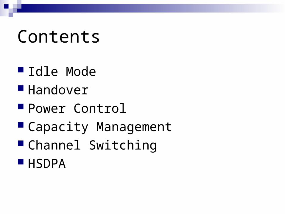
Contents
Idle Mode Handover Power Control Capacity Management Channel Switching HSDPA

Idle Mode and Common Channel behavior
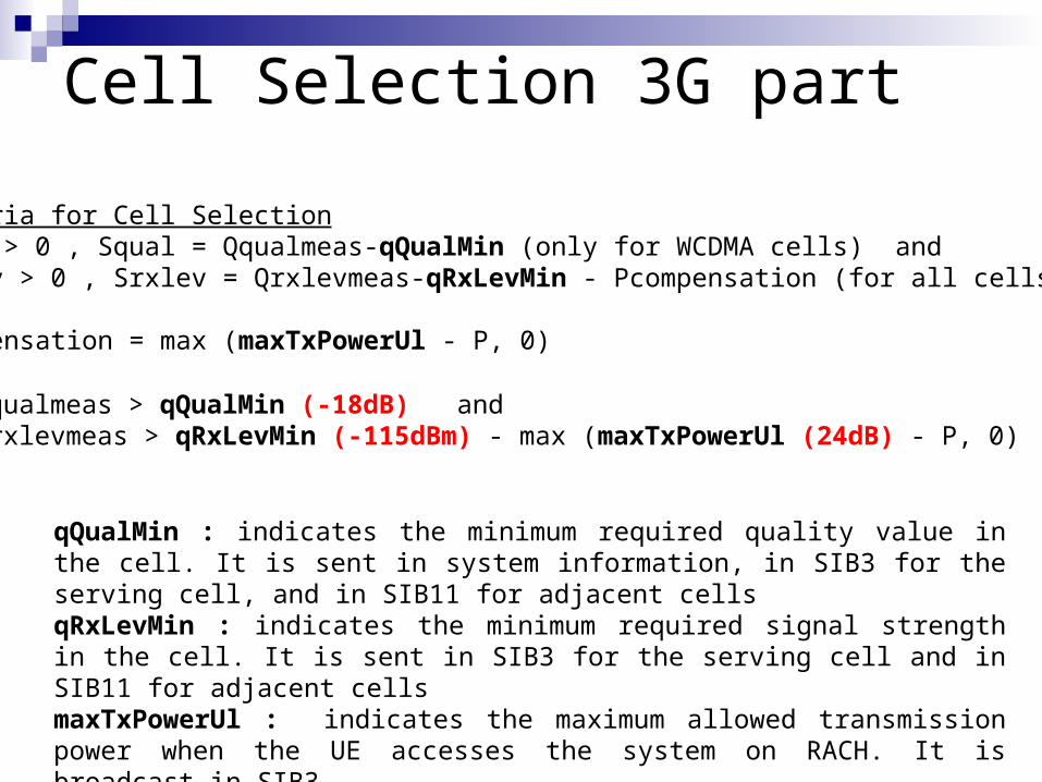
Cell Selection 3G part
Criteria for Cell SelectionSquel > 0 , Squal = Qqualmeas-qQualMin (only for WCDMA cells) and Srxlev > 0 , Srxlev = Qrxlevmeas-qRxLevMin - Pcompensation (for all cells)
Pcompensation = max (maxTxPowerUl - P, 0)
Qqualmeas > qQualMin (-18dB) and Qrxlevmeas > qRxLevMin (-115dBm) - max (maxTxPowerUl (24dB) - P, 0)
qQualMin : indicates the minimum required quality value in the cell. It is sent in system information, in SIB3 for the serving cell, and in SIB11 for adjacent cells qRxLevMin : indicates the minimum required signal strength in the cell. It is sent in SIB3 for the serving cell and in SIB11 for adjacent cellsmaxTxPowerUl : indicates the maximum allowed transmission power when the UE accesses the system on RACH. It is broadcast in SIB3

Cell Selection 3G part
Qqualmeas (dB)(CPICH Ec/N0)
Qrxlevmeas (dBm)CPICH RSCP
qQualMin(–18)
qRxLevMin (–115)
Srxlev > 0Pcompensation
Squal > 0 Squal >0 ANDSrxlev > 0
suitable
cell?
Squal = Qqualmeas – qQualMin
Srxlev = Qrxlevmeas - qRxLevMin – Pcompensation
Pcompensation = max(maxTxPowerUl – P, 0) (dB)
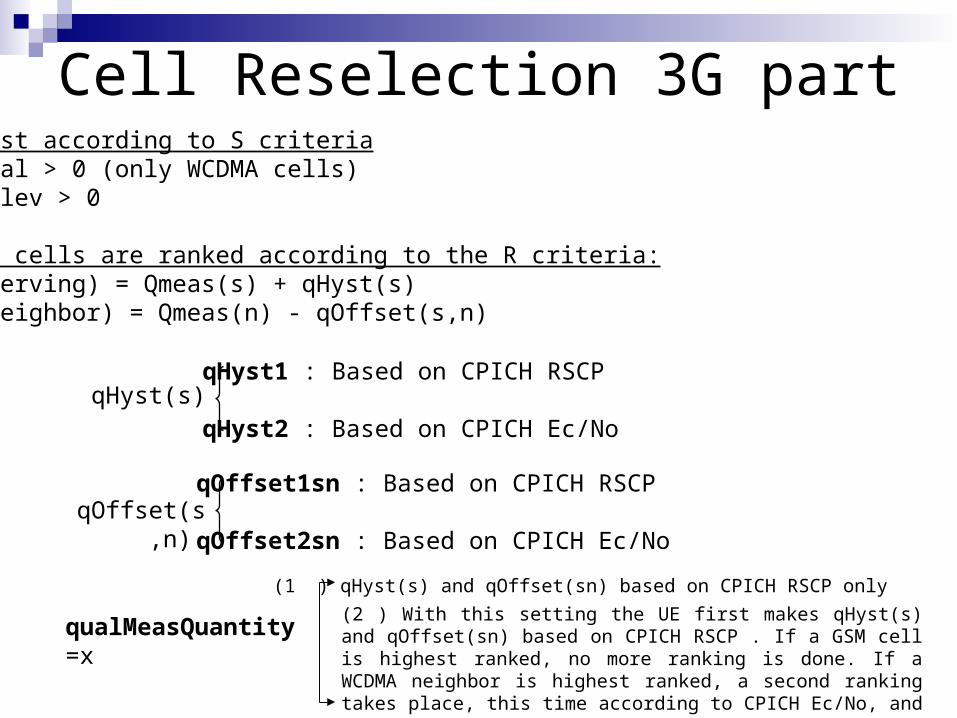
Cell Reselection 3G partFirst according to S criteriaSqual > 0 (only WCDMA cells)Srxlev > 0
The cells are ranked according to the R criteria:R(serving) = Qmeas(s) + qHyst(s)R(neighbor) = Qmeas(n) - qOffset(s,n)
qualMeasQuantity =x
qHyst1 : Based on CPICH RSCP
qHyst2 : Based on CPICH Ec/NoqHyst(s)
qOffset(s,n) qOffset1sn : Based on CPICH RSCP
qOffset2sn : Based on CPICH Ec/No
(1 ) qHyst(s) and qOffset(sn) based on CPICH RSCP only
(2 ) With this setting the UE first makes qHyst(s) and qOffset(sn) based on CPICH RSCP . If a GSM cell is highest ranked, no more ranking is done. If a WCDMA neighbor is highest ranked, a second ranking takes place, this time according to CPICH Ec/No, and excluding all GSM neighbors
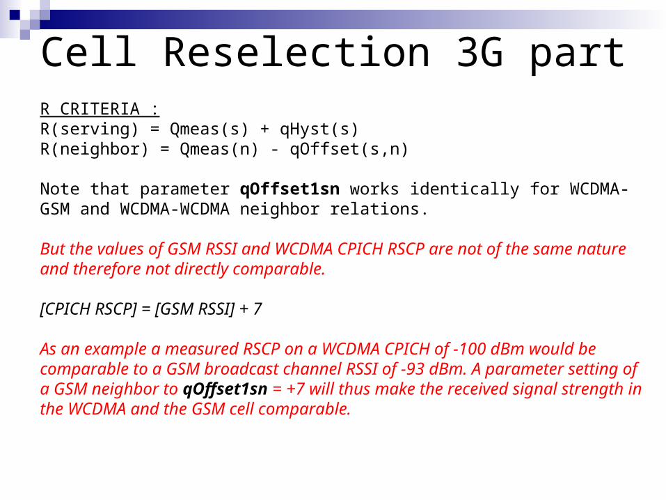
Cell Reselection 3G partR CRITERIA :R(serving) = Qmeas(s) + qHyst(s)R(neighbor) = Qmeas(n) - qOffset(s,n)
Note that parameter qOffset1sn works identically for WCDMA-GSM and WCDMA-WCDMA neighbor relations.
But the values of GSM RSSI and WCDMA CPICH RSCP are not of the same nature and therefore not directly comparable.
[CPICH RSCP] = [GSM RSSI] + 7
As an example a measured RSCP on a WCDMA CPICH of -100 dBm would be comparable to a GSM broadcast channel RSSI of -93 dBm. A parameter setting of a GSM neighbor to qOffset1sn = +7 will thus make the received signal strength in the WCDMA and the GSM cell comparable.
Cell Reselection 3G part
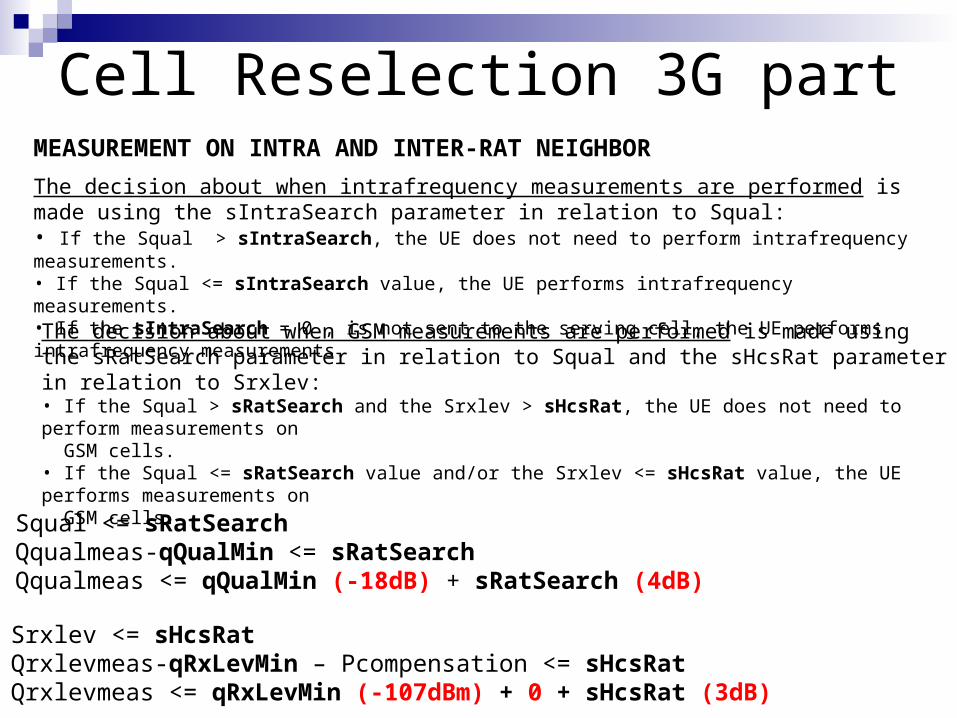
The decision about when intrafrequency measurements are performed is made using the sIntraSearch parameter in relation to Squal: • If the Squal > sIntraSearch, the UE does not need to perform intrafrequency measurements. • If the Squal <= sIntraSearch value, the UE performs intrafrequency measurements. • If the sIntraSearch = 0 , is not sent to the serving cell, the UE performs intrafrequency measurements.
MEASUREMENT ON INTRA AND INTER-RAT NEIGHBOR
The decision about when GSM measurements are performed is made using the sRatSearch parameter in relation to Squal and the sHcsRat parameter in relation to Srxlev:• If the Squal > sRatSearch and the Srxlev > sHcsRat, the UE does not need to perform measurements on GSM cells. • If the Squal <= sRatSearch value and/or the Srxlev <= sHcsRat value, the UE performs measurements on GSM cells.
Squal <= sRatSearchQqualmeas-qQualMin <= sRatSearchQqualmeas <= qQualMin (-18dB) + sRatSearch (4dB)
Srxlev <= sHcsRatQrxlevmeas-qRxLevMin – Pcompensation <= sHcsRatQrxlevmeas <= qRxLevMin (-107dBm) + 0 + sHcsRat (3dB)

Cell Reselection 3G partMeasurements on GSM Neighbors

Cell Reselection 3G partFirst ranking of all the cells based on CPICH RSCP (WCDMA) and RSSI (GSM)
Rs = CPICH RSCP/GSM RSSI + Qhyst1Rn= CPICH_RSCP(n) or RXLEV(n) - Qoffset1
First ranking of all the cells based on CPICH RSCP (WCDMA) and RSSI (GSM)
Rs = CPICH RSCP/GSM RSSI + Qhyst1Rn= CPICH_RSCP(n) or RXLEV(n) - Qoffset1
Rn higher in GSM cellRn higher in GSM cellYes No
Cell re-selection to GSM
Cell re-selection to GSM
Second ranking only for WCDMA cells based on CPICH Ec/No
Rs = CPICH Ec/No + Qhyst2Rn= CPICH Ec/No -Qoffset2
Second ranking only for WCDMA cells based on CPICH Ec/No
Rs = CPICH Ec/No + Qhyst2Rn= CPICH Ec/No -Qoffset2
Cell re-selection to WCDMA cell of highest
R value
Cell re-selection to WCDMA cell of highest
R value
GSM cell measurements
available If :
CPICH Ec/No – qQualMin < SRatSearch
Rs = Serving WCDMA cell
calculation, with
hysteresis parameter
Rn = Neighbour WCDMA or GSM cell calculation with offset parameter
GSM cell measurements
available If :
CPICH Ec/No – qQualMin < SRatSearch
Rs = Serving WCDMA cell
calculation, with
hysteresis parameter
Rn = Neighbour WCDMA or GSM cell calculation with offset parameter
If a TDD or GSM cell is ranked as the best cell, then the UE must perform cell re-selection to that TDD or GSM cell.
If a FDD cell is ranked as the best cell and cell_selection_and_reselection-quality_measure is set to CPICH RSCP, the UE shall perform cell re-selection to that FDD cell.
If a FDD cell is ranked as the best cell and cell_selection_and_reselection-quality_measure is set to CPICH Ec/No, the UE shall perform a second ranking of the FDD cells according to the R criteria using the measurement quantity CPICH Ec/No calculating the R values of the FDD cells.
qHyst1 = 4 dB
qOffset1sn = 0 dB
qQualMin = -18 dB
sRATsearch = 4 dB
qOffset1sn = 7 dB
qRxlevMin = -107 dBm
Qhyst2 = 4 dB
qOffset2sn = 0 dB
RS
CP
RS
SI

Cell Reselection 2G part
Never-54…-70-74-78Always-74…-94-98dBm
1514…109876…10Value
If RLA_C < -94 UE starts 3G
measurements
UE always measures 3G cells
UE never measures 3G cells
If RLA_C > -70 UE starts 3G
measurements
Measurements on 3G Neighbors The parameters QSI and QSC define thresholds and also indicate whether these measurements shall be performed when the signal strength (SS) of the serving cell is below or above the threshold. QSI is used for idle and packet switched modes and broadcast on BCCH and PBCCH (if enabled), while QSC is used for active mode, sent on SACCH
There are 4 different scenarios to choose from. Parameters QSI and QSC are set per GSM cell and define both the scenario and the necessary threshold, at the same time:• UTRAN neighboring cells are measured only when the signal strength of the GSM serving cell is above the threshold set by QSI and QSC• UTRAN neighbor cells are measured only when the signal strength of the GSM serving cell is below the threshold set by QSI and QSC . • UTRAN neighbor cells are always measured. • UTRAN neighbor cells are never measured. This can be used to turn off the cell reselection/handover to UMTS, per cell, even if COEXUMTS is ON for the BSC.

Cell Reselection 2G partExample 1: If an UTRAN cell should serve purely to extend the coverage for Multi-RAT MSs in GSM, it is logical to set QSI /QSC values from 0-6, since it's only needed to make cell reselection and handovers to UMTS when the GSM coverage falls low.
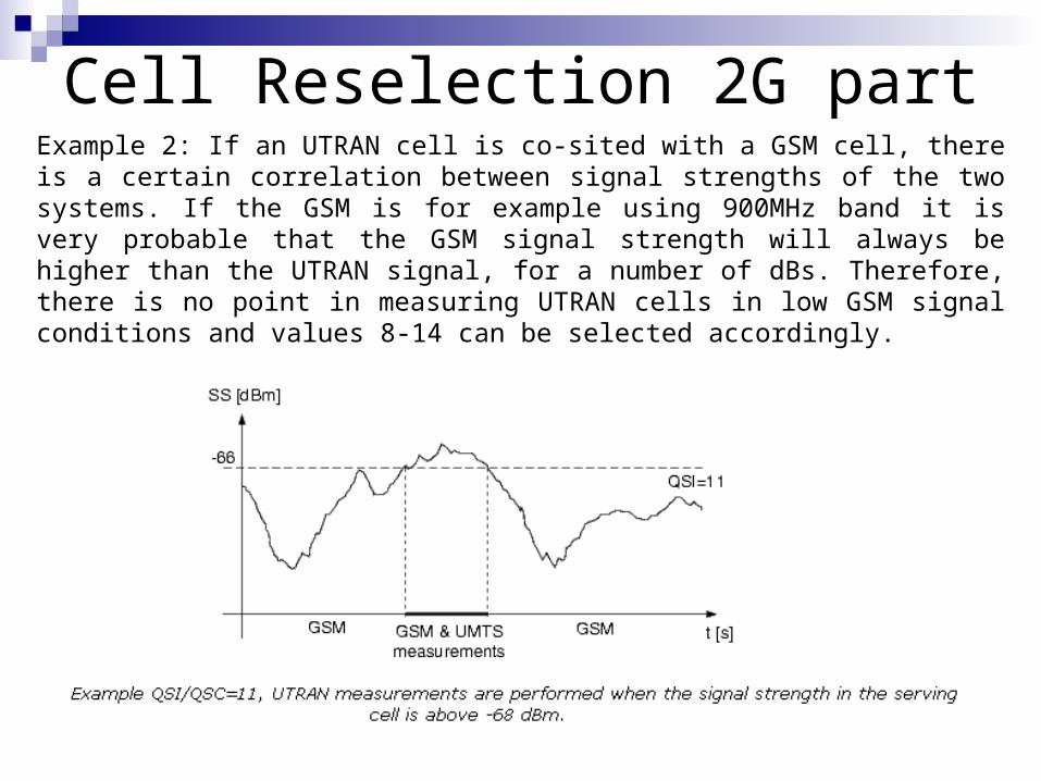
Cell Reselection 2G partExample 2: If an UTRAN cell is co-sited with a GSM cell, there is a certain correlation between signal strengths of the two systems. If the GSM is for example using 900MHz band it is very probable that the GSM signal strength will always be higher than the UTRAN signal, for a number of dBs. Therefore, there is no point in measuring UTRAN cells in low GSM signal conditions and values 8-14 can be selected accordingly.

Cell Reselection 2G part
Criteria :CPICH Ec/No > FDDQMIN (-13dB) andCPICH RSCP > RLA(s+n) + FDDQOFF (-infinite)
2824…0…-20-24-28-32 (infinity)
dBm
1514…8…3210Value
Always select irrespective of RSCP
value
Reselect in case RSCP > GSM RXLev (RLA_C)
+28dB
FDDQOFF
Value 0 1 2 3 4 5 6 7
dBm -20 -19 -18 -17 -16 -15 -14 -13
FDDQMIN

Cell Reselection 2G partCell Reselection List
WCDMA cell
reselection
BCCH: FDDQMIN, FDDQOFF
DEFAULT:fdd cell reselect offset:
select always (value is -infinity)
minimum fdd threshold = -12 dB
DEFAULT:fdd cell reselect offset:
select always (value is -infinity)
minimum fdd threshold = -12 dB
Check levels every 5s from serving GSM cell
and best 6 GSM neighbour cells
UE starts WCDMA measurements if Rxlev running average (RLA_C) is below or above
certain threshold:RLA_C QSI or QSC
UE starts WCDMA measurements if Rxlev running average (RLA_C) is below or above
certain threshold:RLA_C QSI or QSC
UE can select WCDMA cell if the level of the serving GSM and non-serving GSM cells has been
exceeded by certain offset for a period of 5 s:CPICH RSCP > RLA_C + FDDQOFF
RSCP > (aveRxLev) + -32
UE can select WCDMA cell if the level of the serving GSM and non-serving GSM cells has been
exceeded by certain offset for a period of 5 s:CPICH RSCP > RLA_C + FDDQOFF
RSCP > (aveRxLev) + -32
UE will re-select WCDMA cell in case it's quality is acceptable:
CPICH Ec/No FDDQMINEcNo -13
UE will re-select WCDMA cell in case it's quality is acceptable:
CPICH Ec/No FDDQMINEcNo -13
Compare levels of all GSM cells
to WCDMAneighbour
Check quality of neighbour
WCDMA cells, no priorities between
WCDMA neighbours
05
.08
:Th
is m
ay
take
up
to
30
s
QSI = 7(always)
FDDQOFF = -32 dB
FDDQMIN = -13 dB

Idle Mode Parameter SummaryCell Selection and Reselection
accessClassNBarredIndicates whether or not access class N is barred ( N = 0 to 15). 0 : not barred1 : barredStart from least significatant bit:bit 0 : class 0 bit 1 : class 1 bit 2 : class 2 .......bit 15 : class 15
bandIndicatorIndicates the frequency band of the external GSM cell.
The BCCH frequency is unique for all GSM bands except the two GSM bands DCS1800 and PCS1900, so the band indicator is needed to discriminate between the two. When the ExternalGsmCell has a BCCH frequency indicating some other frequency band, then the band indicator is not needed and may be set to "Not applicable".
bcchFrequency BCCH frequency code in the GSM cell. Contains the absolute radio frequency channel number of the BCCH channel for the GSM cell. It uniquely identifies the BCCH.
cellReserved Indicates if this cell shall be reserved for operator use. If it is reserved, there will be no service to the UEs.
fachMeasOccaCycLenCoeffFach Measurement Occasion Cycle Length coefficient. A factor used when the UE performs inter-frequency and inter-system measurements. The UE uses this parameter to calculate the interval length in order to determine the repeating cycle of the measurement.
0 : not broadcasted in SIB 11.1 : not used.2 : not used.3 : used when inter frequency and GSM neighbours.4 : used when inter freqency or GSM neighbours.5 - 12 not used.
interFreqFddMeasIndicator Inter-frequency FDD measurement indicator.
FALSE = NoTRUE = Yes

Idle Mode Parameter SummarymaxTxPowerUl
The maximum UE transmission power on the RACH when accessing the system. Used in UE functions for cell selection/reselection in idle mode and connected mode. Also used by UTRAN to control the maximum TX power level an UE may use.
If the current UE uplink transmit power is above the indicated power value, the UE shall decrease the power to a level below the power value. Value launched by System information (SIB11) for each intra-frequency measurement object corresponding to adjacent cells of serving cell.Unit: 1 dBmResolution: 1 -50: -50 dBm...33: 33 dBm100 : Default value. The parameter is not sent in SIB11 and the UE will use the maximum output power for this GSM cell, according to its radio access capability.
maxTxPowerUl (serving cell, WCDMA neighbor within same RNC)maxTxPowerUl (WCDMA neighbor belonging to another RNC)maxTxPowerUl (GSM neighbor)mcc
The MCC part of the PLMN identity used in the GSM radio network.
The PLMN identity consists of two parts: 1. MobileCountryCode, MCC, 3 digits2. MobileNetworkCode, MNC, 2 or 3 digitsExample: If MCC=125 and MNC=46 then plmnId=12546.
mnc The MNC part of the PLMN identity used in the radio network.
The PLMN identity consists of two parts: 1. MobileCountryCode, MCC, 3 digits2. MobileNetworkCode, MNC, 2 or 3 digitsExample: If MCC=125 and MNC=46 then plmnId=12546.
nmo Network operation mode that indicates whether the Gs interface between the SGSN and MSC/VLR is installed.
primaryScramblingCode The primary downlink scrambling code to be used in the external cell.

Idle Mode Parameter SummaryqHyst1 Cell reselection hysteresis used in UE functions in idle and connected
mode. Value launched by System information (SIB3).
Resolution: 2
qHyst2 The hysteresis value of the serving cell. Used to perform cell ranking for the serving cell.
Resolution: 2
qOffset1sn Signal stength offset between source and target cells. Used when the IE "cell_selection_and_reselection_quality_measure" in SIB 11/12 is set to "CPICH RSCP". This is configured through UtranCell::qualMeasQuantity.
Unit: 1 dBResolution: 1-50 : -50dB-49 : -49dB-48 : -48dB......50 : 50dB
qOffset1sn (WCDMA neighbor relation)qOffset1sn (GSM neighbor relation)qOffset2sn (WCDMA neighbor relation)qQualMin Used in UE functions for cell selection/reselection in idle mode and
connected mode. Minimum required (acceptable) quality level in the cell (dB). Used to set cell border between two cells.
Unit: 1 dBResolution: 1-24 : -24dB......0 : 0dB
100 : Indicates that the minimum quality level has not been specified by the operator. The parameter is then notpresent in SIB11 for this neighbour. The UE will use the serving cell value (UtranCell MO value) instead.
qQualMin (serving cell, WCDMA neighbor within same RNC)qQualMin (WCDMA neighbor belonging to another RNC)

Idle Mode Parameter SummaryqRxLevMin Used in UE functions for cell selection/reselection in idle mode and
connected mode. Minimum required (acceptable) RX level in the cell. (dBm). Value launched by System information (SIB11) for each intra-frequency measurement object corresponding to adjacent cells of serving cell.
Unit: 1 dBmResolution: 2-115 : -115dBm-113 : -113dBm-111 : -111dBm-109 : -109dBm.....-25 : -25 dBm
100 : Indicates that the minimum Rx level has not been specified by the operator. The parameter is then notpresent in SIB11 for this neighbour. The UE will use the serving cell value (UtranCell MO value) instead.
qRxLevMin (serving cell, WCDMA neighbor belonging to same RNC)qRxLevMin (WCDMA neighbor belonging to another RNC)qRxLevMin (GSM neighbor)qualMeasQuantity Used in UE functions for cell selection/reselection in idle and
connected mode. Cell selection and reselection quality measure. Value launched by System information (SIB3, SIB11 and SIB12).
sHcsRat RAT specific threshold in the serving cell used in the inter-RAT measurement rules.
This parameter is used by the UE to decide when to start GSM measurements for cell reselection, if the serving cell is indicated to belong to a Hiearachical Cell Structure (HCS)
GSM measurements in idle mode and state CELL_FACH are started by the UE when RSCP <= qRxLevMin + sHscRat. If sHcsRat is set to a negative value, this will be interpreted as 0 by the UE (according to 3GPP TS 25.331).
Unit: 1 dBResolution: 2
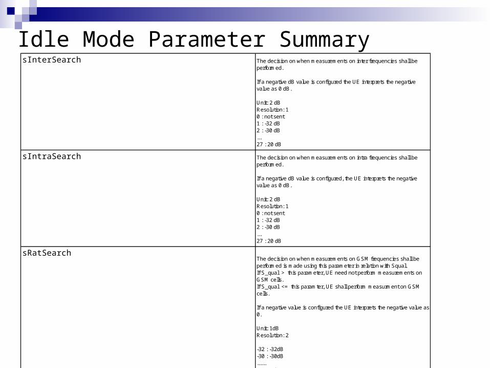
Idle Mode Parameter SummarysInterSearch The decision on when measurements on inter frequencies shall be
performed.
If a negative dB value is configured the UE interprets the negative value as 0 dB.
Unit: 2 dBResolution: 10 : not sent1 : -32 dB2 : -30 dB...27 : 20 dB
sIntraSearch The decision on when measurements on intra frequencies shall be performed.
If a negative dB value is configured, the UE interprets the negative value as 0 dB.
Unit: 2 dBResolution: 10 : not sent 1 : -32 dB2 : -30 dB...27 : 20 dB
sRatSearchThe decision on when measurements on GSM frequencies shall be performed is made using this parameter in relation with Squal. If S_qual > this parameter, UE need not perform measurements on GSM cells.If S_qual <= this paramter, UE shall perform measurment on GSM cells.
If a negative value is configured the UE interprets the negative value as 0.
Unit: 1dBResolution: 2
-32 : -32dB-30 : -30dB......20 : 20dB

Idle Mode Parameter SummarytreSelection Control of cell selection/reselection. Time-to-trigger for cell reselection
in seconds.
Value launched by System information (SIB3).
uarfcnDl Downlink Utra Absolute Radio Frequency Channel Number.
Specifies the channel number for the central DL frequency. The mapping from channel number to physical frequency is described in 3GPP specification TS 25.104.
Unit: Channel numberResolution: N/A
uarfcnUl Uplink Utra Absolute Radio Frequency Channel Number.
Specifies the channel number for the central UL frequency. The mapping from channel number to physical frequency is described in 3GPP specification TS 25.104.
Unit: Channel numberResolution: N/A

Idle Mode Parameter SummaryLocation and Routing Area Updating
att Indicates to the UE whether IMSI attach/detach is allowed. (Some IMSIs are not allowed in some LAs.) This helps to facilitate the avoidance of unnecessary paging attempts. The value is sent on the BCCH.
FALSE: IMSI attach not allowedTRUE: IMSI attach allowed
lAC The Location Area Code of the external GSM cell.
Note: the values 0000 and FFFE are reserved for special cases where no valid LAI exists in the MS.
Old name: lAC
rAC Routing Area Code of a routing area. An RA is used by UTRAN to page mobiles on request from the PS CN.When the parameter is changed, UTRAN shall update system information and notity UEs.
Old name: rAC
t3212 Periodic update timer for LA update.
Unit: 0.1 hours (= 1 decihour = 6 minutes = 360 seconds)Resolution: 1
0 means infinite time, i.e. not

Idle Mode Parameter SummaryPaging
cnDrxCycleLengthCs Core Network DRX cycle length coefficient (k) for UEs in idle mode, circuit switched.
The cycle length is calculated as the k'th potential of 2, where k = 6..9. For example, 6 corresponds to cycle length 640 ms, 7 corresponds to cycle length 1280 ms, etc.
cnDrxCycleLengthPs Core Network DRX cycle length coefficient (k) for UEs in idle mode, packet switched.
The cycle length is calculated as the k'th potential of 2, where k = 6..9. For example, 6 corresponds to cycle length 640 ms, 7 corresponds to cycle length 1280 ms, etc.
noOfMaxDrxCycles Paging notification duration.
To notify UEs in IDLE mode about a system information update, the RNC sends a paging message on the PCH at every page occasion of a number of maximum DRX cycles.
noOfPagingRecordTransm Number of preconfigured subsequent transmissions of the same Paging Record.
System I nformation
noOfMibValueTagRetrans Number of MIB value tag retransmissions on the FACH.
sib1PlmnScopeValueTag The area identity part of PLMN scope value tages for SIB1
sib1RepPeriodsib3RepPeriodsib5RepPeriodsib7RepPeriodsib11RepPeriodsib12RepPeriodsib1StartPossib3StartPossib5StartPossib7StartPossib11StartPossib12StartPossib7ExpirationTimeFactor SIB7 use expiration time as re-read mechanism. The expiration time is
sib7RepPeriod times sib7ExpirationTimeFactor.
updateCellReattsNo Number of update reattempts when an update of system information parameters in a cell failed.
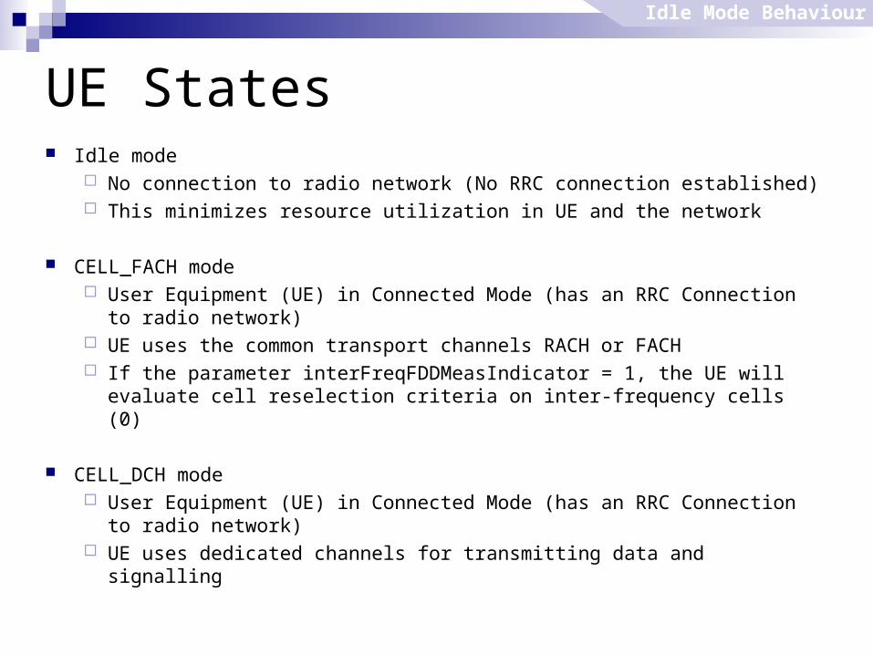
UE States Idle mode
No connection to radio network (No RRC connection established) This minimizes resource utilization in UE and the network
CELL_FACH mode User Equipment (UE) in Connected Mode (has an RRC Connection to
radio network) UE uses the common transport channels RACH or FACH If the parameter interFreqFDDMeasIndicator = 1, the UE will evaluate cell
reselection criteria on inter-frequency cells (0)
CELL_DCH mode User Equipment (UE) in Connected Mode (has an RRC Connection to
radio network) UE uses dedicated channels for transmitting data and signalling
Idle Mode Behaviour
Power Control
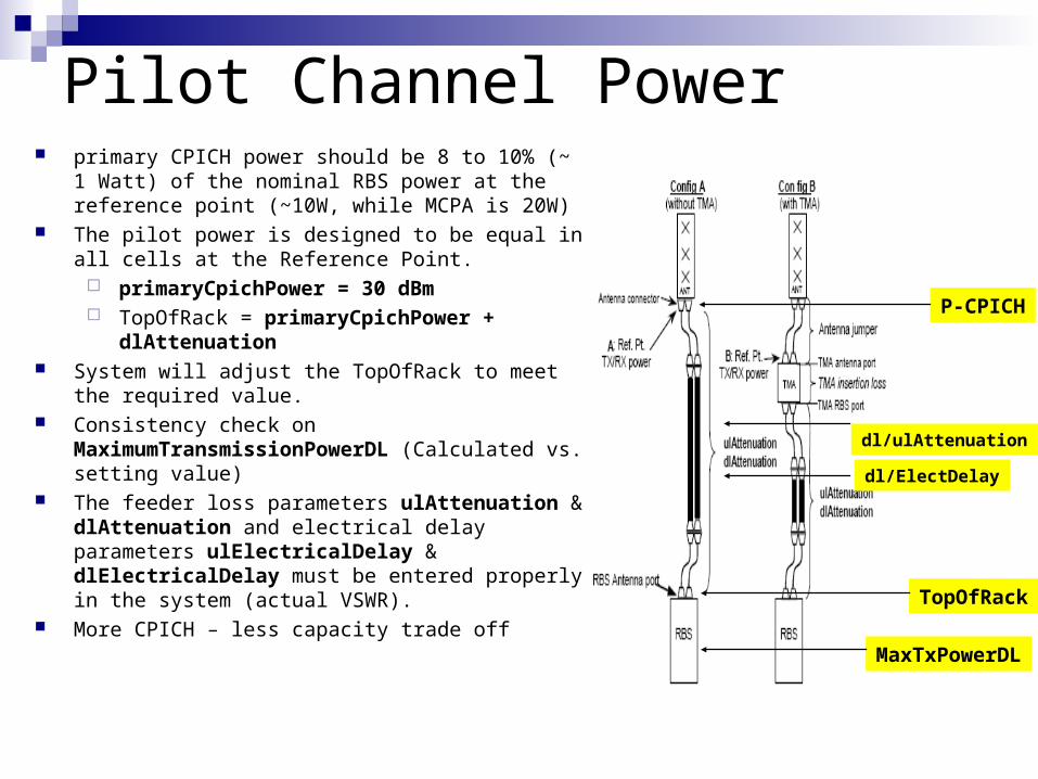
primary CPICH power should be 8 to 10% (~ 1 Watt) of the nominal RBS power at the reference point (~10W, while MCPA is 20W)
The pilot power is designed to be equal in all cells at the Reference Point.
primaryCpichPower = 30 dBm TopOfRack = primaryCpichPower +
dlAttenuation System will adjust the TopOfRack to meet the required
value. Consistency check on
MaximumTransmissionPowerDL (Calculated vs. setting value)
The feeder loss parameters ulAttenuation & dlAttenuation and electrical delay parameters ulElectricalDelay & dlElectricalDelay must be entered properly in the system (actual VSWR).
More CPICH – less capacity trade off TopOfRack
P-CPICH
MaxTxPowerDL
dl/ulAttenuation
dl/ElectDelay
Pilot Channel Power
Common Control Channel Power
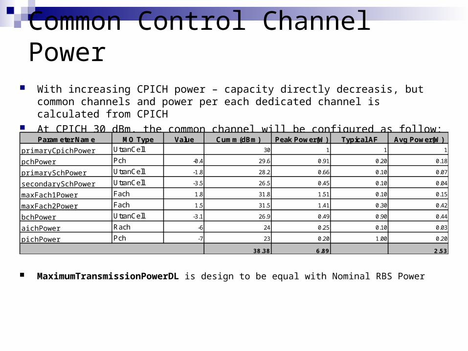
With increasing CPICH power – capacity directly decreasis, but common channels and power per each dedicated channel is calculated from CPICH
At CPICH 30 dBm, the common channel will be configured as follow:
Parameter Name MO Type Value Cumm(dBm) Peak Power(W) Typical AF Avg Power(W)
primaryCpichPower UtranCell 30 1 1 1
pchPower Pch -0.4 29.6 0.91 0.20 0.18
primarySchPower UtranCell -1.8 28.2 0.66 0.10 0.07
secondarySchPower UtranCell -3.5 26.5 0.45 0.10 0.04
maxFach1Power Fach 1.8 31.8 1.51 0.10 0.15
maxFach2Power Fach 1.5 31.5 1.41 0.30 0.42
bchPower UtranCell -3.1 26.9 0.49 0.90 0.44
aichPower Rach -6 24 0.25 0.10 0.03
pichPower Pch -7 23 0.20 1.00 0.20
38.38 6.89 2.53
MaximumTransmissionPowerDL is design to be equal with Nominal RBS Power
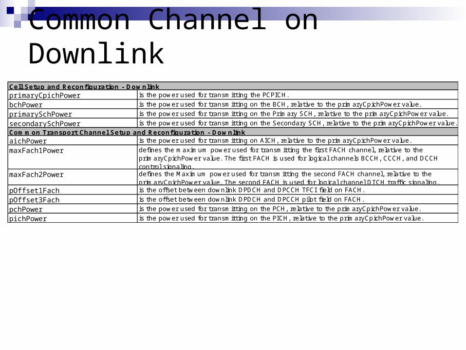
Common Channel on Downlink
Cell Setup and Reconfiguration - DownlinkprimaryCpichPower is the power used for transmitting the PCPICH.
bchPower is the power used for transmitting on the BCH, relative to the primaryCpichPower value.
primarySchPower is the power used for transmitting on the Primary SCH, relative to the primaryCpichPower value.
secondarySchPower is the power used for transmitting on the Secondary SCH, relative to the primaryCpichPower value.
Common Transport Channel Setup and Reconfiguration - DownlinkaichPower is the power used for transmitting on AICH, relative to the primaryCpichPower value.
maxFach1Power defines the maximum power used for transmitting the first FACH channel, relative to the primaryCpichPower value. The first FACH is used for logical channels BCCH, CCCH, and DCCH control signaling.
maxFach2Power defines the Maximum power used for transmitting the second FACH channel, relative to the primaryCpichPower value. The second FACH is used for logical channel DTCH traffic signaling.
pOffset1Fach is the offset between downlink DPDCH and DPCCH TFCI field on FACH.
pOffset3Fach is the offset between downlink DPDCH and DPCCH pilot field on FACH.
pchPower is the power used for transmitting on the PCH, relative to the primaryCpichPower value.
pichPower is the power used for transmitting on the PICH, relative to the primaryCpichPower value.

Common Channel on UplinkCommon Transport Channel Setup and Reconfiguration - UplinkconstantValueCprach is a constant value in dB used by the UE to calculate the initial power on the PRACH according to
the Open Loop Power Control procedure.powerOffsetP0 is the Power ramp step for the preamble when no acquisition indicator is received.
powerOffsetPpm is the Power offset between the last transmitted preamble and the control part of the random access message.
preambleRetransMax is the maximum number of preambles sent in one RACH preamble ramping cycle.
maxPreambleCycle is the maximum number of preamble ramping cycle.
Common Channel on Uplink
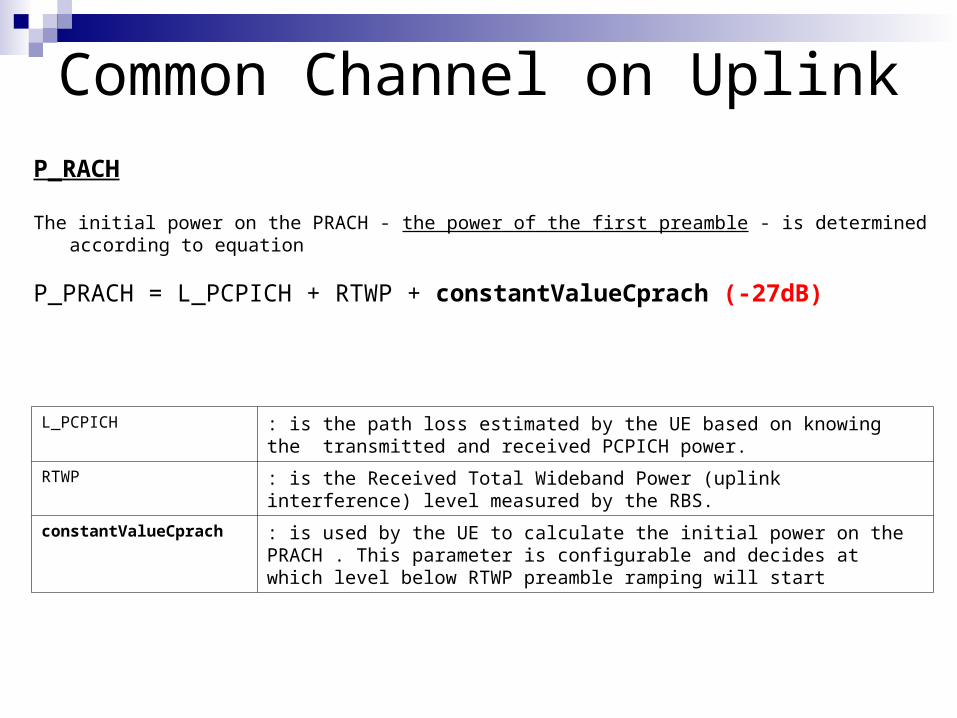
P_RACH
The initial power on the PRACH - the power of the first preamble - is determined according to equation
P_PRACH = L_PCPICH + RTWP + constantValueCprach (-27dB)
L_PCPICH : is the path loss estimated by the UE based on knowing the transmitted and received PCPICH power.
RTWP : is the Received Total Wideband Power (uplink interference) level measured by the RBS.
constantValueCprach : is used by the UE to calculate the initial power on the PRACH . This parameter is configurable and decides at which level below RTWP preamble ramping will start
Common Channel on Uplink
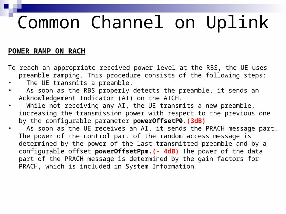
POWER RAMP ON RACH
To reach an appropriate received power level at the RBS, the UE uses preamble ramping. This procedure consists of the following steps:
• The UE transmits a preamble. • As soon as the RBS properly detects the preamble, it sends an Acknowledgement
Indicator (AI) on the AICH. • While not receiving any AI, the UE transmits a new preamble, increasing the transmission
power with respect to the previous one by the configurable parameter powerOffsetP0.(3dB) • As soon as the UE receives an AI, it sends the PRACH message part. The power of the
control part of the random access message is determined by the power of the last transmitted preamble and by a configurable offset powerOffsetPpm.(- 4dB) The power of the data part of the PRACH message is determined by the gain factors for PRACH, which is included in System Information.

Common Channel on UplinkPOWER RAMP ON RACH
preambleRetransMax (8) parameter determines
how many times PRACH preamble can be sent within one preamble ramping cycle (SIB5&6)
maxPreambleCycle (4) defines how many times
the PRACH preamble ramping cycle procedure can be repeated before UE MAC reports a failure on RACH transmission to higher layers (SIB5&6)
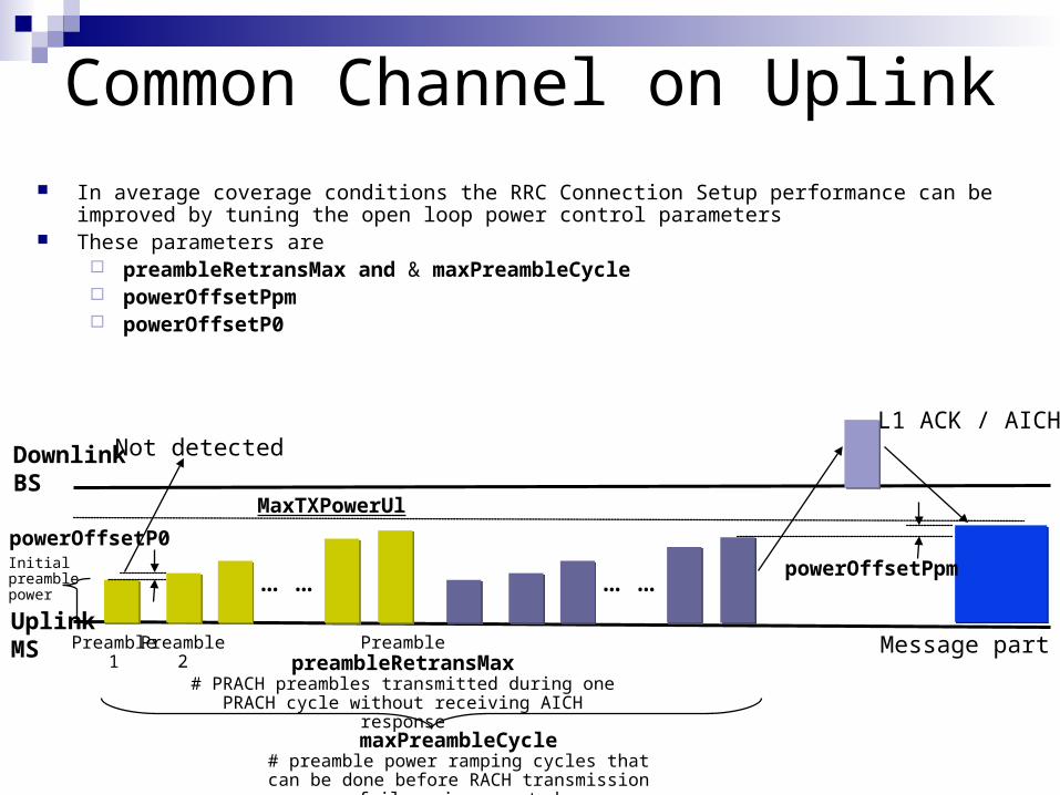
Common Channel on Uplink In average coverage conditions the RRC Connection Setup performance can be improved by tuning
the open loop power control parameters These parameters are
preambleRetransMax and & maxPreambleCycle powerOffsetPpm powerOffsetP0
maxPreambleCycle# preamble power ramping cycles that can be
done before RACH transmission failure is reported
DownlinkBS
L1 ACK / AICH
UplinkMS Preamble
1
Not detected
Message partPreamble2
PreamblepreambleRetransMax
# PRACH preambles transmitted during one PRACH cycle without receiving AICH response
MaxTXPowerUl
… … … …
powerOffsetP0
powerOffsetPpmInitial preamble power

Handover

Soft/Softer Handover Inter-Frequency Handover Inter-RAT Handover Inter-RAT Cell Change HSDPA Mobility

Intra-Frequency Handover SOFTER HANDOVER
MS simultaneously connected to multiple cells (handled by same BTS) No extra transmissions across Iub interface Mobile Evaluated HandOver (MEHO) Both UL and DL: Maximum Ratio Combining (MRC) is occurring in rake receiver
SOFT HANDOVER MS simultaneously connected to multiple cells (from different BTSs) Extra transmission across Iub, more channel cards are needed Mobile Evaluated HandOver (MEHO) DL/UE: MRC UL/RNC: Frame selection combining
HARD HANDOVER Arises when inter-RNC SHO is not possible (Iur not supported or Iur congestion) Decision procedure is the same as SHO (MEHO) Causes temporary disconnection
Inter-Frequency Handover Can be intra-BS, intra-RNC, inter-RNC Network Evaluated HandOver (NEHO)
Inter-RAT (Inter-system) Handover Handovers between GSM and WCDMA (NEHO)
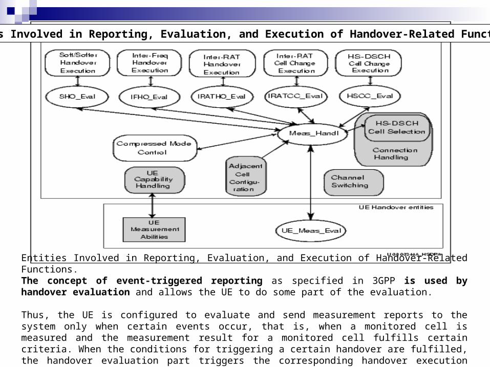
Entities Involved in Reporting, Evaluation, and Execution of Handover-Related Functions. The concept of event-triggered reporting as specified in 3GPP is used by handover evaluation and allows the UE to do some part of the evaluation.
Thus, the UE is configured to evaluate and send measurement reports to the system only when certain events occur, that is, when a monitored cell is measured and the measurement result for a monitored cell fulfills certain criteria. When the conditions for triggering a certain handover are fulfilled, the handover evaluation part triggers the corresponding handover execution part.
Entities Involved in Reporting, Evaluation, and Execution of Handover-Related Functions.

3GPP-defined UE Associated Cell sets for Measurement
Active Set •The cells involved in soft handover and measured by the UE
Virtual Active Set•The Active Set associated with a non-used frequency for support of Inter-Frequency evaluation
Monitored Set •The cells only measured by the UE and not part of the Active Set. The monitored set can consist of intra-frequency, Inter-Frequency and Inter-RAT cells
Detected Set•The intra frequency cells(P-CPICH scrambling codes) detected by the UE but not part of Active Set or monitored set

Soft/Softer HandoverEvent 1a, A primary CPICH enters the Reporting Range
(measured P-CPICH Ec/No) > (P-CPICH Ec/No of the Best Cell in the Active Set) - reportingRange1a + hysteresis1a /2
Event 1b, A primary CPICH leaves the Reporting Range
When a P-CPICH, not included in the Active Set, enters reportingRange1a + hysteresis1a/2, and the measured value remains in reportingRange1a + hysteresis1a/2 at least a time equal to timeToTrigger1a (Time to Trigger 1a), event 1a occurs. The UE sends a MEASUREMENT REPORT message for event 1a to the SRNC. If the report contains more than one cell fulfilling 1a criteria, only the one with highest Ec/No is considered and retained. If the retained cell is a valid cell and Active Set is not full (present cells in the Active Set is less than maxActiveSet parameter), the cell is proposed to be added to the Active Set. If the Active Set is full, the cell is proposed as a replacement of the worst cell in the Active Set provided that the reported cell has a better quality than the worst cell in the Active Set.
(measured P-CPICH Ec/No) < (P-CPICH Ec/No of the best cell in the Active Set) - reportingRange1b - hysteresis1b /2
When a P-CPICH, included in the Active Set, leaves reportingRange1b - hysteresis1b /2, and the measured value is outside reportingRange1b - hysteresis1b /2 during a time at least equal to timeToTrigger1b, event 1b occurs. The UE sends a MEASUREMENT REPORT message for event 1b to the SRNC. The handover algorithms will remove the reported cells one by one from the Active Set, however one cell is always kept in the Active Set for maintaining the connection.

Soft/Softer Handover
Cell (P_CPICH2) Would be proposed to be included in Active Set List
Cell (P_CPICH2) Would be proposed to be excluded from Active Set List
Event 1a and Event 1b
6dB10dB
320 ms 640 ms
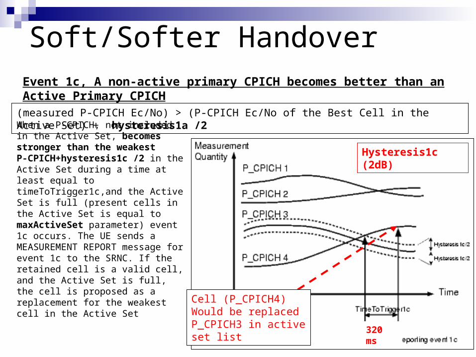
Event 1c, A non-active primary CPICH becomes better than an Active Primary CPICH
Soft/Softer Handover
When a P-CPICH, not included in the Active Set, becomes stronger than the weakest P-CPICH+hysteresis1c /2 in the Active Set during a time at least equal to timeToTrigger1c,and the Active Set is full (present cells in the Active Set is equal to maxActiveSet parameter) event 1c occurs. The UE sends a MEASUREMENT REPORT message for event 1c to the SRNC. If the retained cell is a valid cell, and the Active Set is full, the cell is proposed as a replacement for the weakest cell in the Active Set
(measured P-CPICH Ec/No) > (P-CPICH Ec/No of the Best Cell in the Active Set) + hysteresis1a /2
Cell (P_CPICH4) Would be replaced P_CPICH3 in active set list
Hysteresis1c (2dB)
320 ms

Soft/Softer HandoverParameter Summary
Setting Value RemarkreportingRange1a 6 3 dB
reportingRange1b 10 5 dB
timeToTrigger1a 11 320ms
timeToTrigger1b 12 640ms
timeToTrigger1c 11 320ms
timeToTrigger1d 14 2560ms
hysteresis1a 0 0
hysteresis1b 0 0
hysteresis1c 2 1dB
hysteresis1d 15 7dB
maxActiveSet 3 3
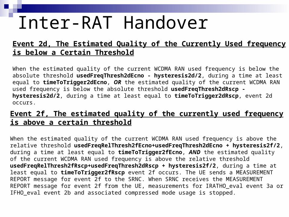
Inter-RAT HandoverEvent 2d, The Estimated Quality of the Currently Used frequency is below a Certain Threshold
When the estimated quality of the current WCDMA RAN used frequency is below the absolute threshold usedFreqThresh2dEcno - hysteresis2d/2, during a time at least equal to timeToTrigger2dEcno, OR the estimated quality of the current WCDMA RAN used frequency is below the absolute threshold usedFreqThresh2dRscp - hysteresis2d/2, during a time at least equal to timeToTrigger2dRscp, event 2d occurs.
Event 2f, The estimated quality of the currently used frequency is above a certain threshold
When the estimated quality of the current WCDMA RAN used frequency is above the relative threshold usedFreqRelThresh2fEcno+usedFreqThresh2dEcno + hysteresis2f/2, during a time at least equal to timeToTrigger2fEcno, AND the estimated quality of the current WCDMA RAN used frequency is above the relative threshold usedFreqRelThresh2fRscp+usedFreqThresh2dRscp + hysteresis2f/2, during a time at least equal to timeToTrigger2fRscp event 2f occurs. The UE sends a MEASUREMENT REPORT message for event 2f to the SRNC. When SRNC receives the MEASUREMENT REPORT message for event 2f from the UE, measurements for IRATHO_eval event 3a or IFHO_eval event 2b and associated compressed mode usage is stopped.
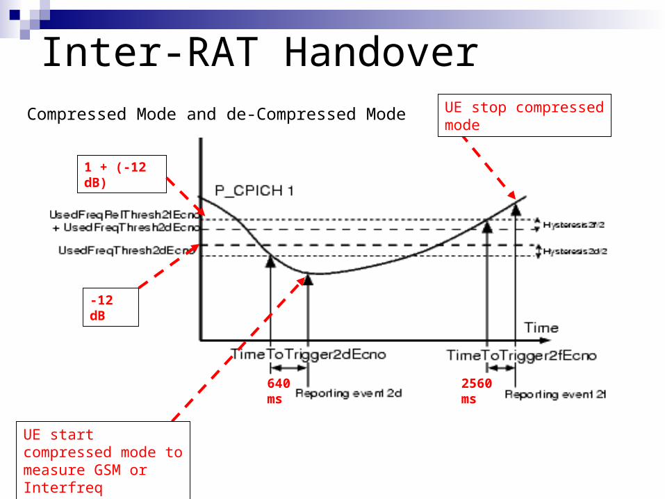
Inter-RAT Handover
UE start compressed mode to measure GSM or Interfreq Neighbors
UE stop compressed mode
-12 dB
1 + (-12 dB)
640 ms 2560 ms
Compressed Mode and de-Compressed Mode
Event 3a, The Estimated Quality of the Currently Used UTRAN Frequency is below a Certain Threshold and the Estimated Quality of the Other System is above a Certain Threshold
The event 3a occurs according to the following points:• When the estimated quality of the WCDMA RAN used frequency is below the threshold usedFreqThresh2dEcno+utranRelThresh3aEcno - hysteresis3a/2 and the measured GSM carrier RSSI of a GSM/GPRS cell is above the absolute threshold gsmThresh3a, during a time at least equal to TimeToTrigger3a
• when the estimated quality of the WCDMA RAN used frequency is below the threshold usedFreqThresh2dRscp+utranRelThresh3aRscp - hysteresis3a/2 and the measured GSM carrier RSSI of a GSM/GPRS cell is above the absolute threshold gsmThresh3a, during a time at least equal to TimeToTrigger3a
• in case of the connection quality has been triggered in UL for UE TX power (event 6a, see Event 6a, The UE Tx Power becomes larger than an Absolute Threshold), the event 3a is triggered when the estimated quality of the WCDMA RAN used frequency is below the threshold usedFreqThresh2dRscp+utranRelThresh3aRscp+utranRelThreshRscp - hysteresis3a/2 and the measured GSM carrier RSSI of a GSM/GPRS cell is above the absolute threshold gsmThresh3a , during a time at least equal to TimeToTrigger3a.
Inter-RAT Handover
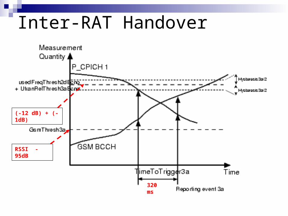
Inter-RAT Handover
(-12 dB) + (-1dB)
RSSI -95dB
320 ms

IFHO & IRAT Parameter Summary
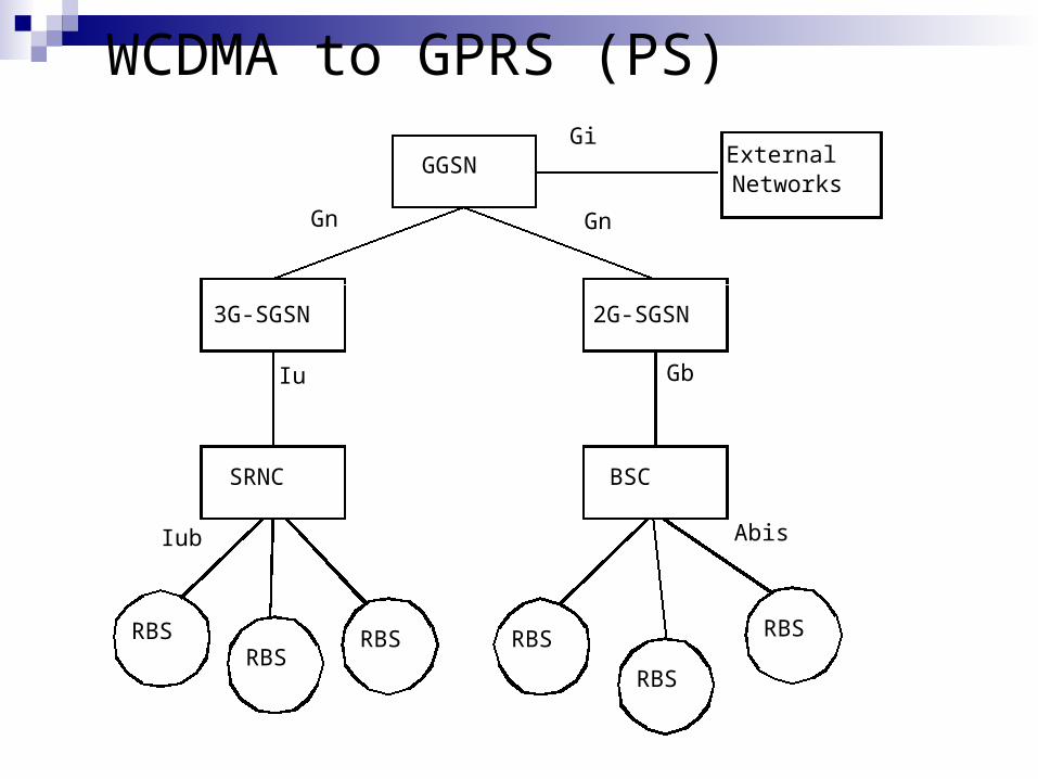
WCDMA to GPRS (PS)
3G-SGSN
SRNC BSC
2G-SGSN
GGSN
RBSRBS
RBS RBS
RBS
RBS
Iu Gb
AbisIub
GnGn
ExternalNetworks
Gi
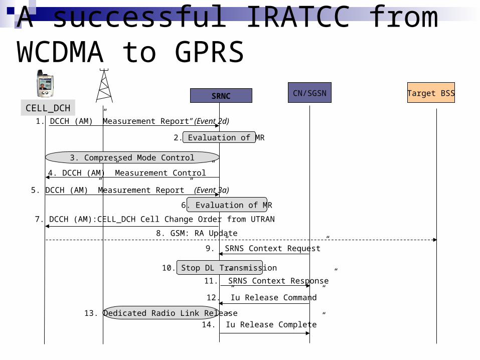
SRNC CN/SGSN Target BSS
CELL_DCH1. DCCH (AM) ”Measurement Report” (Event 2d)
2. Evaluation of MR
3. Compressed Mode Control
4. DCCH (AM) ”Measurement Control”
5. DCCH (AM) ”Measurement Report” (Event 3a)
6. Evaluation of MR
7. DCCH (AM):CELL_DCH Cell Change Order from UTRAN
8. GSM: RA Update
10. Stop DL Transmission
12. ”Iu Release Command”
14. ”Iu Release Complete”
13. Dedicated Radio Link Release
A successful IRATCC from WCDMA to GPRS
9. ”SRNS Context Request”
11. ”SRNS Context Response”
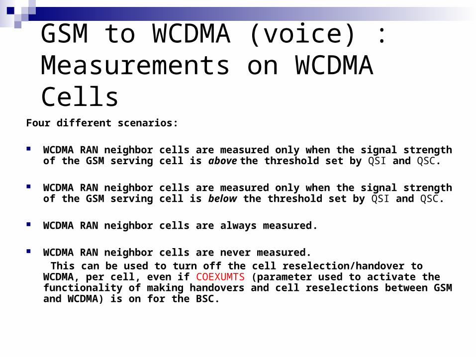
GSM to WCDMA (voice) : Measurements on WCDMA Cells
Four different scenarios:
WCDMA RAN neighbor cells are measured only when the signal strength of the GSM serving cell is above the threshold set by QSI and QSC.
WCDMA RAN neighbor cells are measured only when the signal strength of the GSM serving cell is below the threshold set by QSI and QSC.
WCDMA RAN neighbor cells are always measured.
WCDMA RAN neighbor cells are never measured. This can be used to turn off the cell reselection/handover to WCDMA, per cell,
even if COEXUMTS (parameter used to activate the functionality of making handovers and cell reselections between GSM and WCDMA) is on for the BSC.


Load sharing

Load sharing
• Load sharing to 2nd carrier at RRC establishment
Least loaded cell (Highest difference between power and pwradm) is chosen by sending RRC connection reject with redirection info to 2nd carrier.
• Directed Retry to GSM at RAB establishment
When Dl power reaches ‘loadSharingGsmThreshold’ percentage of pwradm, calls are targeted to be offloaded to GSM. This is achieved by rejecting RAB establishment requests with ‘directed retry’ as a cause.

Load sharing capabilities available in the WCDMA RAN
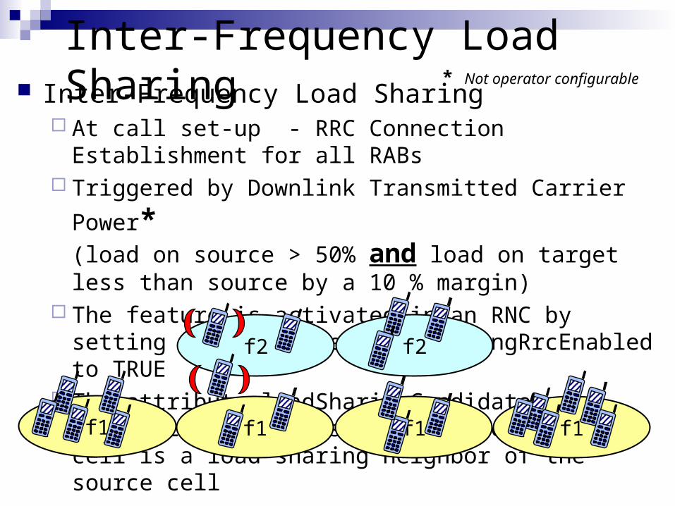
Inter-Frequency Load Sharing Inter-Frequency Load Sharing
At call set-up - RRC Connection Establishment for all RABs
Triggered by Downlink Transmitted Carrier Power*
(load on source > 50% and load on target less than source by a 10 % margin)
The feature is activated in an RNC by setting the parameter loadSharingRrcEnabled to TRUE
The attribute loadSharingCandidate TRUE/FALSE specifies whether the target cell is a load-sharing neighbor of the source cell
f1 f1f1 f1
f2 f2
* Not operator configurable

Inter-Frequency Load Sharing (RRC redirection) (Extra Slide)
RNCRNC
”RRC Connection Request” CCCH/RACH
”RRC Connection Reject” CCCH/FACH
Idle Mode
Cell selection on designated UTRA carrier
”RRC Connection Request” CCCH/RACH
”RRC Connection Setup” CCCH/FACH
F1
F2
Includes ‘Frequency Info’ IE
2nd will not be redirected but may be successful or rejected due to
congestion
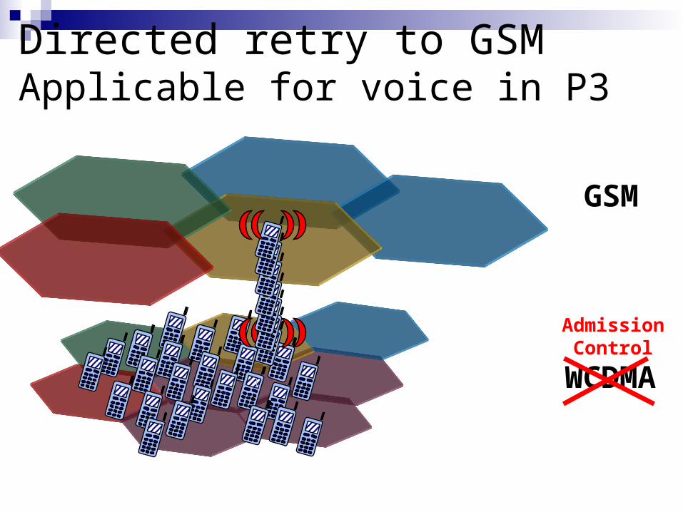
Directed retry to GSMApplicable for voice in P3
WCDMA
GSM
AdmissionControl

Directed retry to GSM Directed retry to GSM
At call set-up - RAB Establishment for voice Triggered by Downlink Transmitted Carrier Power
The feature is activated in an RNC by setting the parameter loadSharingDirRetryEnabled to TRUE
One GSM target can be defined for each WCDMA cell via the cell parameter directedRetryTarget
loadSharingGsmThreshold specifies the minimum load at which off-loading to GSM begins: ex 80% of pwrAdm
loadSharingGsmFraction specifies the percentage of Directed Retry candidates to be diverted to GSM while the cell load is above the specified load threshold

Directed Retry to GSM
UE RBS/RNC CN
Directed Retry decision to send
Successful access to GSM
Contacts GSM cell and orders
relocation
HO from UTRAN command
RAB Assignment Request
RAB Assignment Response (failed, cause=directed retry)
Relocation Required
Relocation Command
Iu release Command
Iu release Complete
Voice calls can be relocated to GSM due to high load in WCDMAIf the call is not accepted in GSM - try in WCDMA again!

When out of coverage, the WCDMA voice call is handed over to GSM
When GSM load reaches a customizable threshold, voice calls can be handed over to WCDMA
GSM coverage
Dual Mode UE
GSM terminal
Load balancing for voice between WCDMA-GSM
Load based handover to GSM during call set up, Directed Retry (P3) to GSM
IntroductionFeatures & Roadmap
WCDMA coverage
Channel Switching
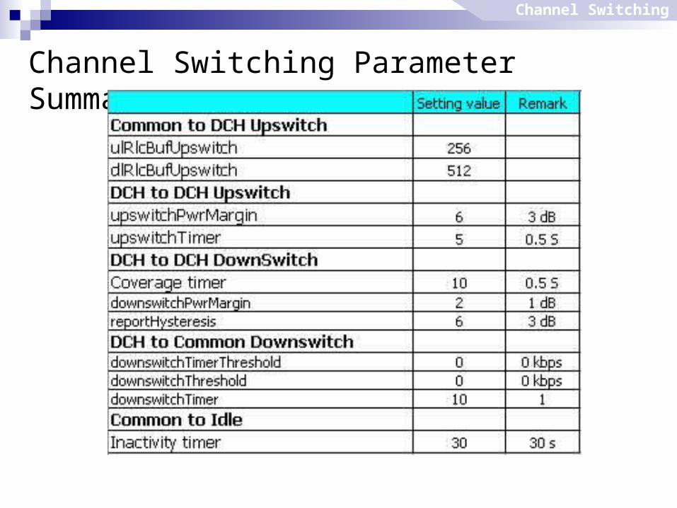
Channel Switching Parameter Summary
Channel Switching
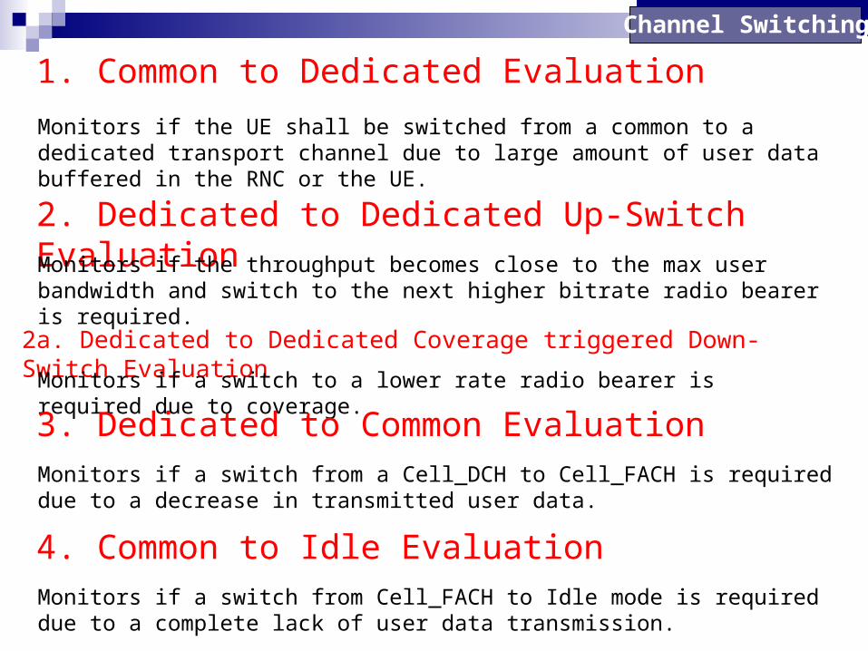
1. Common to Dedicated Evaluation
Channel Switching
Monitors if the UE shall be switched from a common to a dedicated transport channel due to large amount of user data buffered in the RNC or the UE.
2. Dedicated to Dedicated Up-Switch EvaluationMonitors if the throughput becomes close to the max user bandwidth and switch to the next higher bitrate radio bearer is required.
2a. Dedicated to Dedicated Coverage triggered Down-Switch Evaluation
Monitors if a switch to a lower rate radio bearer is required due to coverage.
3. Dedicated to Common EvaluationMonitors if a switch from a Cell_DCH to Cell_FACH is required due to a decrease in transmitted user data.
4. Common to Idle EvaluationMonitors if a switch from Cell_FACH to Idle mode is required due to a complete lack of user data transmission.

Multi-RAB Down-switch Evaluation
Channel Switching
Monitors if a release (or downswitch) of PS I/B RAB shall be initiated due to lack of PS data throughput (zero), resulting in a single speech 12.2 kbps (or speech + PS 0/0) or CS64 RAB.
Multi-RAB Up-switch EvaluationMonitors if an upswitch from multi-RAB SP0 to multi-RAB SP64 shall be initiated due to data buffered in either RNC or UE.
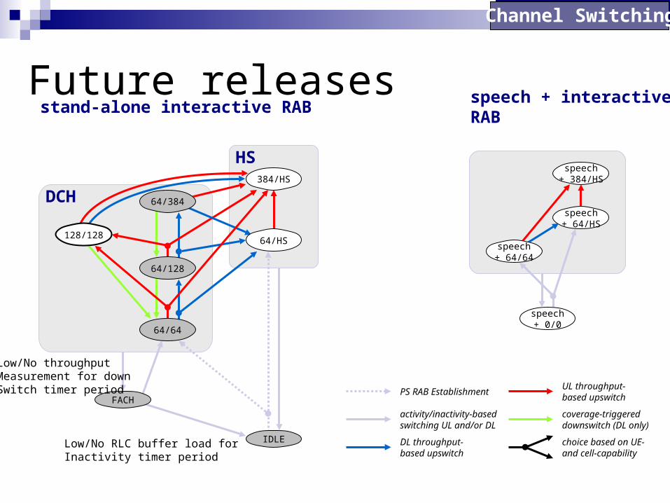
Future releases
Channel Switching
activity/inactivity-basedswitching UL and/or DL
DL throughput-based upswitch
UL throughput-based upswitch
coverage-triggereddownswitch (DL only)
choice based on UE- and cell-capability
IDLE
FACH
DCH
HS384/HS
64/384
64/HS
64/128
64/64
128/128
stand-alone interactive RAB
speech+ 0/0
speech+ 64/64
speech+ 64/HS
speech+ 384/HS
speech + interactiveRAB
PS RAB Establishment
Low/No RLC buffer load forInactivity timer period
Low/No throughputMeasurement for downSwitch timer period

Capacity Management
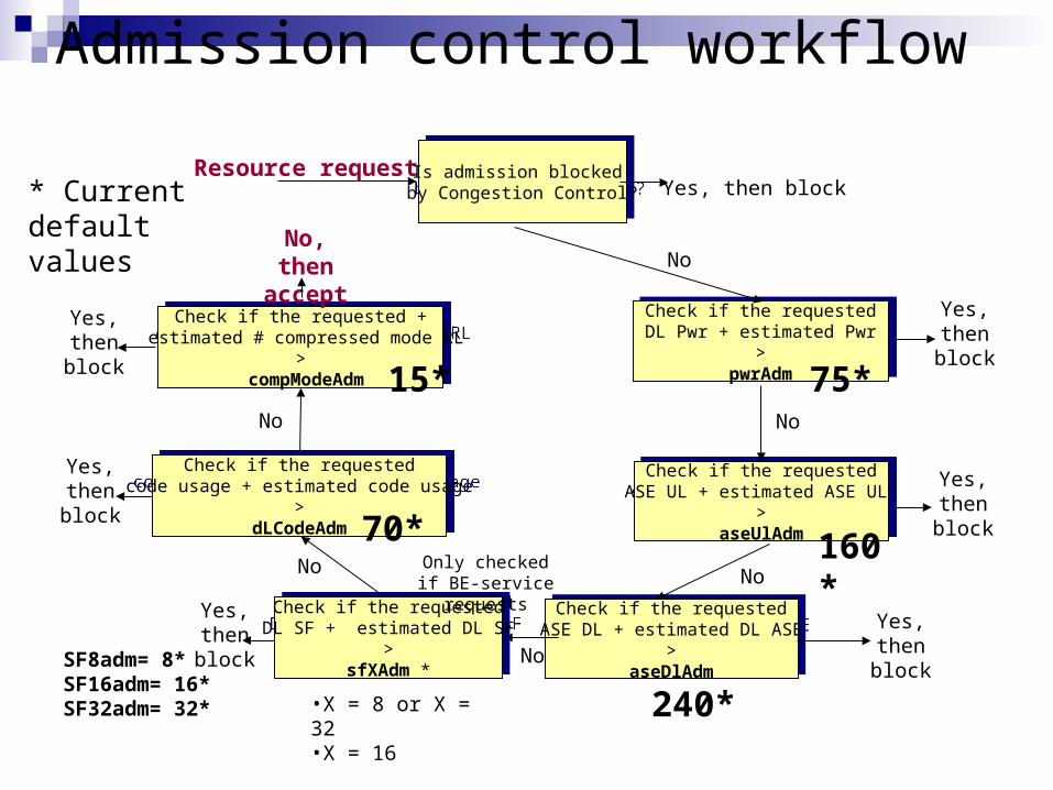
Admission control workflow
Resource request Is admission blocked by Congestion Control?Is admission blocked
by Congestion Control?
Yes, then block
Check if the requestedASE UL + estimated ASE UL
>aseUlAdm
Check if the requestedASE UL + estimated ASE UL
>aseUlAdm
No
Yes, then block
Check if the requestedDL Pwr + estimated Pwr
>pwrAdm
Check if the requestedDL Pwr + estimated Pwr
>pwrAdm
No
Yes, then block
Check if the requested + estimated # compressed mode RL
> compModeAdm
Check if the requested + estimated # compressed mode RL
> compModeAdm
No
Yes, then block
No, then accept
Check if the requestedASE DL + estimated DL ASE
>aseDlAdm
Check if the requestedASE DL + estimated DL ASE
>aseDlAdm
No
Yes, then block
Yes, then block
Check if the requestedcode usage + estimated code usage
>dLCodeAdm
Check if the requestedcode usage + estimated code usage
>dLCodeAdm
No
No
Yes, then block
Check if the requestedDL SF + estimated DL SF
>sfXAdm *
Check if the requestedDL SF + estimated DL SF
>sfXAdm *
Only checked if BE-service requests
•X = 8 or X = 32•X = 16
75*
160*
240*
SF8adm= 8* SF16adm= 16*SF32adm= 32*
70*
15*
* Current default values
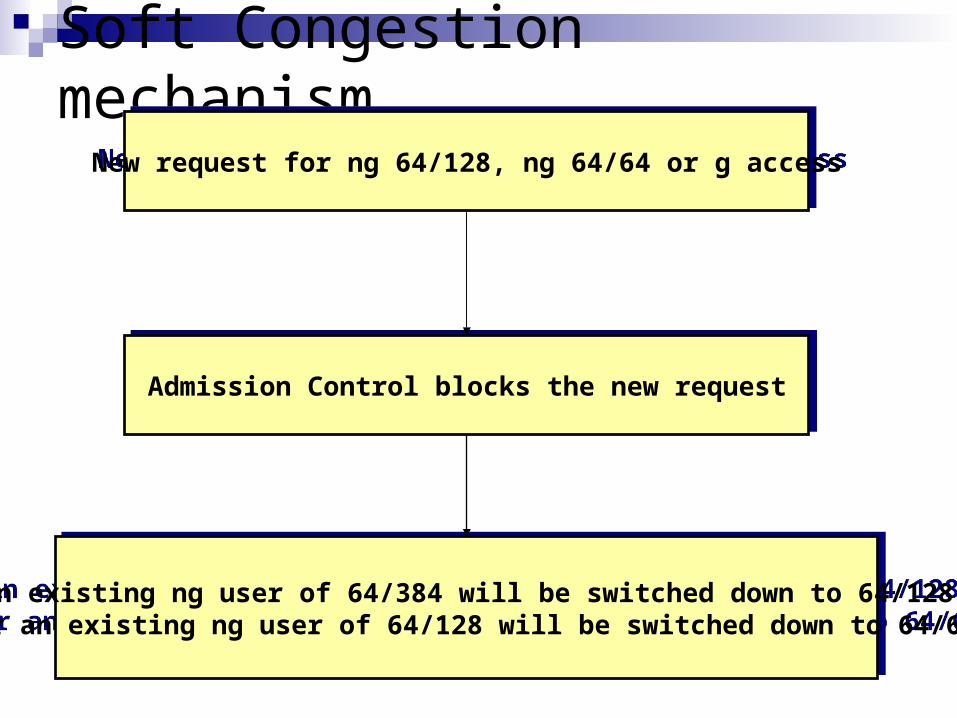
Soft Congestion mechanism
New request for ng 64/128, ng 64/64 or g accessNew request for ng 64/128, ng 64/64 or g access
Admission Control blocks the new requestAdmission Control blocks the new request
An existing ng user of 64/384 will be switched down to 64/128 or an existing ng user of 64/128 will be switched down to 64/64An existing ng user of 64/384 will be switched down to 64/128
or an existing ng user of 64/128 will be switched down to 64/64
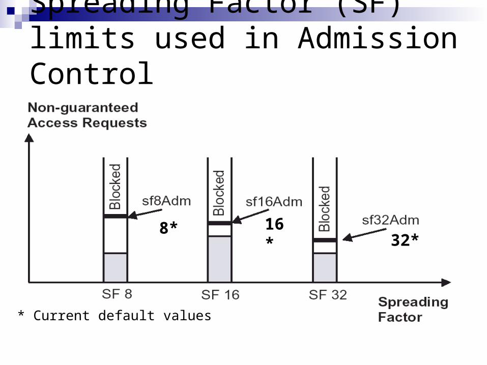
Spreading Factor (SF) limits used in Admission Control
8* 16*32*
* Current default values
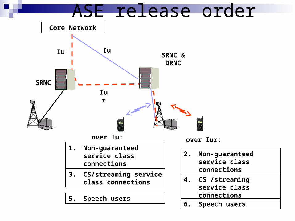
ASE release orderCore Network
SRNC & DRNC
Iu
Iur
over Iur:
SRNC
Iu
over Iu:
1. Non-guaranteed service class connections
3. CS/streaming service class connections
5. Speech users
2. Non-guaranteed service class connections
4. CS /streaming service class connections
6. Speech users
HSDPA

HSDPA Parameter SummaryParameter Name Default Value
Initial Setting TELKOMSEL
HSPATHLOSSTHRESHOLD
170 170
CQIERRORSABSENT 10 10
HSPOWERMARGIN 2 2
HSSCCHMAXCODEPOWER
-20 -20
QUEUESELECTALGORITHM
ROUND_ROBIN
ROUND_ROBIN
SUPPORTOF16QAM FALSE TRUE
MAXHSRATE 15 30
HSONLYBESTCELL 1 1
HSHYSTERESIS1D 10 10
HSQUALITYESTIMATE CPICH_RSCP CPICH_RSCP
HSTIMETOTRIGGER1D 640 640
MAXHSRATE
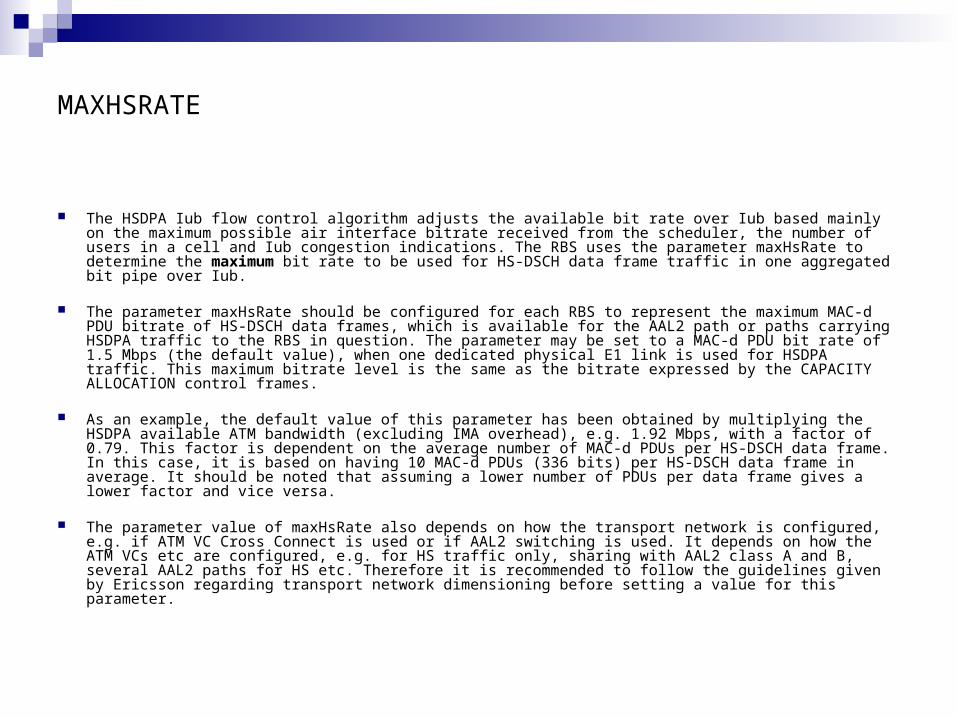
The HSDPA Iub flow control algorithm adjusts the available bit rate over Iub based mainly on the maximum possible air interface bitrate received from the scheduler, the number of users in a cell and Iub congestion indications. The RBS uses the parameter maxHsRate to determine the maximum bit rate to be used for HS-DSCH data frame traffic in one aggregated bit pipe over Iub.
The parameter maxHsRate should be configured for each RBS to represent the maximum MAC-d PDU
bitrate of HS-DSCH data frames, which is available for the AAL2 path or paths carrying HSDPA traffic to the RBS in question. The parameter may be set to a MAC-d PDU bit rate of 1.5 Mbps (the default value), when one dedicated physical E1 link is used for HSDPA traffic. This maximum bitrate level is the same as the bitrate expressed by the CAPACITY ALLOCATION control frames.
As an example, the default value of this parameter has been obtained by multiplying the HSDPA available ATM bandwidth (excluding IMA overhead), e.g. 1.92 Mbps, with a factor of 0.79. This factor is dependent on the average number of MAC-d PDUs per HS-DSCH data frame. In this case, it is based on having 10 MAC-d PDUs (336 bits) per HS-DSCH data frame in average. It should be noted that assuming a lower number of PDUs per data frame gives a lower factor and vice versa.
The parameter value of maxHsRate also depends on how the transport network is configured, e.g. if ATM VC Cross Connect is used or if AAL2 switching is used. It depends on how the ATM VCs etc are configured, e.g. for HS traffic only, sharing with AAL2 class A and B, several AAL2 paths for HS etc. Therefore it is recommended to follow the guidelines given by Ericsson regarding transport network dimensioning before setting a value for this parameter.
16QAM Modulation
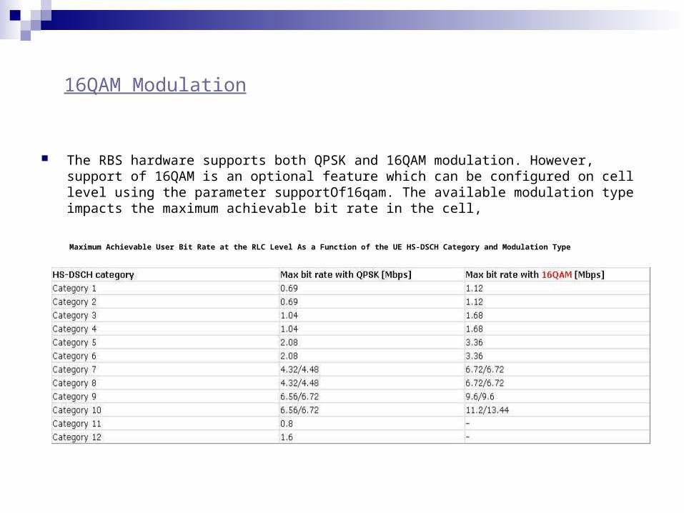
The RBS hardware supports both QPSK and 16QAM modulation. However, support of 16QAM is an optional feature which can be configured on cell level using the parameter supportOf16qam. The available modulation type impacts the maximum achievable bit rate in the cell,
Maximum Achievable User Bit Rate at the RLC Level As a Function of the UE HS-DSCH Category and Modulation Type