
3flIIIIIIIflfflfIIf IIIIIIIIIIIIIIfflfflf EIIIEEIIIEEEI ... · resume and dispatch execution...
230
6-AQ94 482 PERCEPTRONICS INC WOOOLANO HILLS CALIF F/S / MAN-MACHINE COMMUNICATION IN REMOTE MANIPULATION- TASK-ORIENTED- ETCMA O 0CU ROS AFEO OOI 6C00 JNCLASSIFIEO PFTR-1034 80-3 NL ,, 3flIIIIIIIflfflfIIf "IIIIIIIIIIIIIIfflfflf EIIIEEIIIEEEI EIIIIIIIIIIIIu IIEIIIIIIEEEI IIEIIEIIIEIII IIIIIIEEEIIE
Transcript of 3flIIIIIIIflfflfIIf IIIIIIIIIIIIIIfflfflf EIIIEEIIIEEEI ... · resume and dispatch execution...
6-AQ94 482 PERCEPTRONICS INC WOOOLANO HILLS CALIF F/S /MAN-MACHINE COMMUNICATION IN REMOTE MANIPULATION- TASK-ORIENTED- ETCMA
O 0CU ROS AFEO OOI 6C00
JNCLASSIFIEO PFTR-1034 80-3 NL,, 3flIIIIIIIflfflfIIf"IIIIIIIIIIIIIIfflfflfEIIIEEIIIEEEIEIIIIIIIIIIIIuIIEIIIIIIEEEIIIEIIEIIIEIIIIIIIIIEEEIIE

tf
4_

-4 ,
AAl
C4,0
~V
* f,.- -
~5a-
4t
:4. ~Ak*

I
Final Technical Report PFTR-1034-80-3Contract N00014-76-C-0803
NR 196-140March, 1980
i MAN-MACHINE COMMUNICATION IN REMOTE MANIPULATION:TASK-ORIENTED SUPERVISORY COMMAND LANGUAGE
* (TOSC)
Yee-Yeen Chu A c' e-si-n ForWilliam H. Crooks NTTS C-",t\I
Amos Freedy DTIC TA"
jj** 1 . ,. _
S IH Prepared For:
* IEngineering Psychology Programs (code 455)OFFICE OF NAVAL RESEARCH
Department of the NavyArlington, VA 22217
I
I
I PERCEPTRONICSI 6271 VARIEL AVENUE 0 WOODLAND HILLS 6 CALIFORNIA 11367 PHONE (213) 184-7470tI& ~'4J

i\
.1 SHARED MAN COMPUTER CONTROL
II-
~ N " .

ACKNOWLEDGEMENTS
In addition to the authors, contributions to this research effort were
made by the following Perceptronics personnel: Dr. Efraim Shaket, Senior
Scientist; Dr. Gershon Weltman, President and Chief Scientist; Mr.
Johathan Klein, Research Associate; Mr. Yoram Alperovitch, Associate Soft-
ware Engineer; Mr. Michael Rector, Associate Scientist, and Mr. Denis
Purcell, Senior System Engineer.
The authors extend their appreciation to Mr. Gerald Malecki of the Office
of Naval Research for his encouragement and counsel in the conduct of
this research.
ii
* -----I---~# *.
TABLE OF CONTENTS
Page
1. INTRODUCTION 1-1
1.1 Summary 1-11.2 Technical Approach 1-4
1.2.1 Computer-AidodManipulation 1-41.2.2 Command Language Development 1-61.2.3 Experimental Program 1-7
1.3 Report Organization 1-8
2. UNDERWATER MANIPULATION WITH SHARED MAN-COMPUTER CONTROL 2-1
2.1 Overview 2-12.2 Teleoperator Task Identification 2-1
2.2.1 Methods of Specifying Teleoperator Control Tasks 2-42.2.2 Task Description at Operation Level 2-42.2.3 Task Description at Motion Level 2-102.2.4 Environmental Factors in Underwater Manipulation 2-13
2.3 Operator Activity Analysis 2-15
2.3.1 Supervisory Function Hierarchy 2-182.3.2 Teleoperator Control Task and Information
Requirements 2-22
2.4 Man-Machine Interaction 2-28
3. TASK-ORIENTED SUPERVISORY CONTROL SYSTEM METHODOLOGY 3-1
3.1 Overview 3-13.2 Background 3-3
3.2.1 General 3-33.2.2 Preliminary Principles of Command Language Design 3-43.2.3 Preliminary Principles of Feedback Display Design 3-9
3.3 Man-Machine Communication Models 3-12
3.3.1 Background 3-123.3.2 Adapted Procedure Nets Framework 3-15
'

TABLE OF CONTENTS (CONTINUED)
Page
3.4 Syntactic Analysis of the Task-Oriented SupervisoryCommand Language 3-20
3.4.1 Analog Versus Symbolic Command 3-223.4.2 Keyboard Arrangement and Feedback Format 3-243.4.3 Language Primitives 3-313.4.4 Chains 3-383.4.5 Summary of TOSC Language Features 3-42
4. EXPERIMENTAL STUDY 4-1
4.1 Overview 4-14.2 Evaluation of Man-to-Machine Communication 4-2
4.2.1 Control and Programming 4-74.2.2 Command Mix 4-94.2.3 Command Organization 4-124.2.4 Summary of Man-to-Machine Communication 4-15
4.3 Evaluation of Machine-to-Man Communication 4-19
4.3.1 Machine State Feedback Level 4-224.3.2 Machine State and Evnironmental Feedback Formats 4-244.3.3 Summary of Machine-to-Man Communication 4-36
5. DISCUSSIONS OF RESULTS AND RECOMMENDATIONS 5-1
5.1 Overview 5-15.2 Issues in the Design and Evaluation of Man-Machine
Communication 5-2
5.2.1 Performance Dimensions of Man-Machine Communication 5-25.2.2 Critical Factors Affecting Task Performance 5-75.2.3 System Approaches of Man-Machine Communication
Evaluation 5-115.2.4 A Simple Model for Predicting Improved Time
Performance 5-13
5.3 System Extention and Future Research Needs 5-26
5.3.1 Extension of TOSC Language 5-265.3.2 Future Research Needs 5-27
1*I i
TABLE OF CONTENTS (CONTINUED)
Page
6. REFERENCES 6-1
APPENDIX A - SYSTEM APPLICATION GUIDELINES A-i
APPENDIX B - COMPUTER-AIDED MANIPULATION FACILITY B-i
APPENDIX C - LIST OF REPORTS AND PUBLICATIONS C-1
DISTRIBUTIUN LIST
DD 1473 FORM
I.
I
i.

1. INTRODUCTION
11 Summary
This report covers the~fdu research anddevelopment directed toward the investigation and optimization of man-
machine communication in computer-aided remote manipulation. The purpose
of this program was to determine through analytical and experimental
studies the relationships between primary man-machine communication factors
and system performance, and to develop and demonstrate a communication
design methodology to improve operator performance with remotely controlled
systems.
Specific prersobjectives included the following:
(1) To perform an analysis of communications requirements in
computer-aided manipulation and closely related areas of
adaptive and autonomous control
(2) To establish an experimental system for study of task-oriented
supervisory control of a remote manipulato,-tFigure 1-1).-
(3) o implement and evaluate communication systems, encompass-
ing both language and interface, designed to permit natural
and efficient control of a variety of remote manipulation
tasks,,
(4) /1o identify the primary factors influencing the success of
AI shared man-computer control, and to establish quantitativerelationships between these factors and the system performance
measures, a,_l
(5) 4 o provide guidelines for the design of man-computer communi-
cation in subsequent autonomous, adaptive and remotely-manned
systems
,li 1-1
- -... "+-+ "] " " -.+"

MAN-MACHINE INTERFACE
MINICOMPUTER
SERVO-MAN IPULATOR
FIGURE 1-.1.COMPUTER-AIDED REMOTE MANIPULATIONEXPERIMENTAL FACILITY
$ 1-2

The initial year's work established a theoretical commnunications framework
based on procedural nets, and examined experimentally the separate effects
of several basic computer aiding techniques on the ability of trained
operators to perform selected manipulation tasks. The experimental results
indicated that computer aiding, in the form of real-time transformation
from joint angle to resolved motion control (RMC) of the end point,
significantly reduces the time required and the number of errors committed
in performing most manipulation tasks. Computer aiding in the form of
automatic motion control (AMC) to specifiable locations did not provide
immuiediate performance improvement but showed potential usefulness for some
well-specified manipulation tasks. The training results also suggested
that computer aiding can be used to reduce the time required for personnel
to become accomplished manipulator operators.
The second year's study emphasized the development of the procedural net
model into a language model. This led to the development of a specific
manipulation language and the corresponding control/display design con-
cepts. The language structure, through the definition and execution of
symbolic commands, provides the user with a flexible mechanism to define
and use task oriented commands. The experimental study indicated that
these pre-defined variable commands can significantly reduce task time
to perform a repetitive task. These data also suggested that the benefitof variable commands increases with practice and that the organizationof the commands helps to reduce the number of errors in a complex task.
The third year's study provided the extension and evaluation of the high
level command structure and the needed feedback information to the operator
regarding task state and system status. The experimental results indicated
that the high level construct of a command can significantly improve taskperformance when tasks are discrete with low trajectory complexity, orU when tasks are operated under degraded visibility. The study also
Is 1-3

suggeatea that a commiand-queue display with appropriate format and updaterate can serve as both memory and task monitor aids.
The work reported here comprises the fourth year of the program and con-solidates the results of current and previous studies in determining the
relationship between man-machine communications factors and operator per-
formance.
First presented, is a taxonomy of shared man-computer control in under-
water manipulation developed to expand the domain of test results. Rel-
ative evaluations of the manned system performance level are discussed
next. These evaluations are determined as functions of primary commuuni-
cations factors, including command structure, control mode, and feedback
mode. The work ends with the presentation of a performance prediction
model and a set of principles and guidelines, applicable to the design
of man-machine interface, particularly the structure of multi-mode command
inputs, apportionment of control functions between operator and computer,
and methods for structuring feedback information to the operator.
1.2 Technical Approach
1.2.1 Computer-Aided Manipulation. Advances in computer-aided tele-
operator control offer the potential for substantially improving the
effectiveness of Navy underwater manipulator systems. Computer-aided
control can be used, with reasonable cost, to improve system effectiveness
by performing coordinate transformations to simplify simultaneous joint
movements and by reducing operator task loading by allowing the operator
to allocate certain task elements to machine automation. As we extend
manual control of the manipulator system to the full range capabilityki afforded by the computer element, the problems of man-machine communication
become of great importance. An effective, closely coupled man-computer
1-4

communication interface is needed because the task environment requires
great flexibility and dexterity in planning and operation. The sparse
evidence suggests that when this communication is awkward, computer-aidedcontrol of remote manipulation can be inferior to manual control. Whatis needed, then, is a systematic investigation of critical communicationfactors, and a new method for extracting and organizing task relatedinformation commiunicated between human operator and computer to implementefficient control systems.
As a major step toward the identification of critical communicationfactors, observations need to be made concerning the major dimensions ofoperator activities with a given task. In most manipulation tasks, theoperator must observe the task environment, make judgments about the
commands necessary to perform the task, and carry out the command execu-tion while maintaining observation of the manipulator within the task
environment. As the situation varies, the sequence and the complexity of
the above operator activities may vary. In addition, the activities and,
more fundamentally, the role of the operator could be changed with the
introduction of computer aiding techniques. A typical example is the useof a set of sampled aiding techniques organized in a shared man-computer
control framework. In such a case, which was examined in this program,
the operator not only provides direct analog control of the manipulator'smovements, but also he must (1) organize command sequences, (2) select
any of a number of computer-assisted functions, (3) monitor the mode ofoperation and the progress of automated routines, and (4) be able toresume and dispatch execution functions. A wide range of communicationmodes, encompassing a wide spectrum of augmented and autonomous manipula-
tion, is therefore required for effective use of computers in remotemani pulati on.
1-5

Accordingly, the approach in the present program was to focus on the
general rules for constructing special-purpose communication languages
for effective shared man-computer control. The use of remote manipula-
tion represents a good example of a bounded (limited-bandwidth) commuuni-
cations area, one which is important in its own right to Navy operational
goals. Language elements have been implemented at the man-computer inter-
face. The relationship of variation in these elements to total system
performance has provided the data upon which practical human factors
design guidelines will be based.
1.2.2 Commnand Language Development. The p evious year's work included
the development of a communication model which forms the basis for the
man-machine language design. A hierarchical model based on the concept L
of procedural net was developed to represent the planning process of
manipulator action. The procedural net is a conceptual framework that
models the process of plan development. The problem domain is described
as a hierarchy of tasks and subtasks at various levels of abstraction.
Each task node consists of a goal statement of what has to be accomplished
by the task, an object on which the action is performed, and an action--I
the sequence of subtasks expressed at a lower level of abstraction. The
specific sequence needed to accomplish a task is a function of both the
state of the environment and what is requested at higher levels of theglobal task.
The procedural net model described above was adapted to represent the man-machine commnunication process as a step in the overall planning process.
That is, the human operator develops the global task into a plan at some
intermediate level of detail which he then coimunicates to the computer.j
The computer develops the plan further to the level of detail necessary
for controlling the manipulator and proceeds to monitor the plan executionvia position and force-sensor feedback. The language developed from this
,Ali1-6

model is hierarchical, flexible, and task-oriented, allowing close cooper-
ation between man and machine with a mixed initiative protocol of control
allocation. Using this model, a task-oriented supervisory control (TOSC)
language was designed which facilitates computer-aided manipulation. The
main features of the language include the following:
(1) User-defined, hierarchical-structured commands.
(2) Command chains as concepts at various task levels.
(3) Sentence-structured keyboard command.(4) Mixed-initiative control.
(5) Intermixing of analogic and symbolic, complex and simplecommands.
(6) Machine state and command queue feedback organized around
task hierarchy with the level of detail in correspondence
with the operator's planning level.
1.2.3 Experimental Program. The objective of the overall experimentalprogram was to evaluate techniques for improved man-machine communication
in computer-aided remote manipulation. The major dimensions under investi-
gation were:
(1) Command Language Structure. The manner by which the operator
transmits comm~ands to the remote element. The levels of thisdimension are (1) Manual Commands, whereby the operator actu-
ates analogic or symbolic control motions, (2) Variable
Commands, in which the operator uses defined points, paths
or the linkage of individual symbolic commands, (3) Chained
(Automatic) Commands, in which the operator defines a multi-level sequence of commands which can then be performed auto-
mati cal ly.
1-7

(2) Machine State Feedback. The information concerning the con-
trol mode and commnand queue established for the chained
command mode of control. The levels of this dimension are
(1) full delineation of the individual comm~ands and their
sequence, and (2) display of the currently operational
commnand only.
(3) Visual Feedback. Visual observation of the manipulator in
work space. The levels of this dimension are: (1) normal
TV viewing, (2) degraded TV, and (3) stick-figure graphic
display.
The experimental studies were conducted using the Perceptronics' facility
for computer-controlled manipulation. This facility, developed and pro-
gramm~ed in the previous years of the program, provides the necessary
capabilities for testing language features, input/output protocol and
feedback display levels. The manipulator itself is a dexterous, hydraulic-
ally-powered unit, combining quick response accuracy and high strength.The manipulator is commianded through a dedicated keyboard and joysticks,
designed according to the commnand language guidelines, along with a CRTdisplay for feedback of machine state information, two-view video displayand a3D stick-figure graphic to simulate remote operations.
1.3 Report Organization
v The organization of this report is as follows: Chapter 2 describes thedevelopment of the taxonomy for shared man-computer control of teleopera-
tion, emphasizing underwater manipulation. Chapter 3 presents the
developed task-oriented supervisory command (TOSC) language and the
studies and the implications of the research findings. -Chapter 5 gen-
eralizes the test results and discusses the issues in manned system evalu-
ation and performance model development.
1-8

2. UNDERWATER MANIPULATION WITH SHARED MAN-COMPUTER CONTROL
2.1 Overview
This chapter presents the results of a taxonomical analysis of underwater
manipulation that is suitable for a shared man-computer control approach.
The taxonomy is descriptive in nature and identifies task dimensions
suitable for characterizing the effects of man-machine communication
factors over operator performance. It also provides a basis for generali-
zing the method and data achieved in our man-machine communication languagedesign. Therefore, the emphasis here has not been to develop a rigorous
classification scheme, but rather to provide a framework for evaluating
and extending the experimental findings in terms of their application tovarious types of tasks. As such, the procedure of the study included a
brief literature review, technical discussions with members in therelated research areas, analyses of task attributes and requirements, and
cross-examination of experimental findings. The topics discussed in the
following sections represent those areas closely related to man-machine
commnunications: low-level manipulation, environmental factors, machine
characteristics (automation levels), and man-machine interaction factors.
2.2 Teleoperator Task Identification
A task can be viewed as the totality of the situation imposed on the
operator or teleoperator. Here, teleoperator is referred to as "a general-
purpose, dexterous, man-machine system that augments the operator byprojecting his manipulatory capability across distance and through physical
barriers" (Corliss and Johnsen, 1968). Figure 2-1a illustrates a functional
representation of a general teleoperator system. Top-level functionaldescriptions of the subprocesses and the interactions between them are pre-
sented in the context of a remote manipulation environment. The major
subprocesses of operator activities include:
2-1

REO4
(a) ELEPERTORCONROLTAS
OPERATOR OPERATORJNOERWATER MISSIONS TASK DEMANDS ACTIV ITIES PERFORANCE
312VER'S TASKS 7 EROVERALL.
r ELEOPERATOR SYSTEM CHARACTERISTICS NOR TINCOGNITIVE. REMOTE
* SUPERVISORY FUNCTIONS ACTIVITIES
E NVIRONMENTAL FACTORS
(b) OPERATOR TASK
FIGURE 2-1.TELEOPERATOR TASK ANALYSIS
2-2 r

(1) Perception: including event sensing, which continously
senses and manages data flow; and data synthesis, which
updates situation estimates.
(2) Cognition: including problem recognition, which identifies
conflicts or problems; and planning, which synthesizes and
refines commnand/actions.
(3) Execution: including plan selection, which provides trade-
offs between procedures; and commnand execution, which
trades between activation and monitoring functions.
It appears that the operator's task, which is the main concern of this
study, is determined by the teleoperator task demand, the environmental
factors, and the specific teleoperator system given (i.e., the types of
manipulator, tools, sensors, and computer-aiding available). Therefore,
along with the discussions contained in the next few sections, a major
effort will be devoted to map and build the operator task taxonomy out
of the existing data sources of teleoperator task taxonomies. The
"demand" side of task analysis, as described in Figure 2-1b, starts with
the collection of underwater manipulation tasks based on the following
sources:
(1) Navy underwater missions and commiercial ocean operations.
(2) Diver's tasks.
(3) Underwater environmental factors.
(4) Teleoperator systems (including manipulators, tools, sensors).
(5) Supervisory control approaches (computer aiding).
(6) Planning and cognitive activities of everyday manipulation.
* The "performance" side of task analysis will be expanded by a set of
performance criteria. The detail of the performance study will be dis-
cussed in Chapter 5, while the following section concentrates on demand.4 and activity analysis.
2-3

In the following sections the term "task" will refer to either teleoperator
task or operator task, dependingon the context.
2.2.1 Methods of Specifying Teleoperator Control Tasks. Consider the
teleoperator systems which are used to carry out some desired interaction
with the underwater environment. Since it is impossible to abstractly
model the complete physical environment, the abstract description of
teleoperator-environments interaction is necessarily limited. Therefore,
models that embody physical, geometrical, temporal and spatial character-
istics are employed as components to describe an ongoing manipulation
situation. Various approaches for task analysis were summarized by
Sheridan and Verplank (1978), including task breakdown (e.g., Bien and
McDonough, 1968), functional and information requirement analysis (e.g.,
Schneider, 1977), time-line or time-precedence analysis (e.g., Pesch,
et al., 1970; Ocean System, Inc., 1977), and formal process descriptions
(e.g., Whitney, 1969). These approaches are used when they are suitable
for task analysis at different levels of detail. In our approach to the
demand-side analysis, a teleoperator task is viewed as a black box Itranslating information and functional requirements into operator acti-
vities. The requirements associated with the spectrum of underwater jmission were derived through the following method. First, the scope of
mission and functional operations to be performed by the state-of-the-art
teleoperator were determined, and typical operations were selected to
focus the task analysis on uncovering a spectrum of manipulation functions.
This analysis, together with the review of documents generated in the past,
provided a summary of current and projected underwater tasks.
2.2.2 Task Description at Operation Level. A useful list of tasks a
manipulator can perform in underwater missions was given by Drenning,
and is presented in Table 2-1. To be more specific about the manipula-tive capability required, two functional operations listed in the Tablewere considered for more detailed analysis: offshore production and
2-4

TABLE 2-1
TYPES OF TASKS A MANIPULATOR CAN PERFORM ON UNDERWATER MISSIONS
SalvageDetach cables restraining objects to be salvagedClear debris away from objects to be salvagedPrepare objects for lifting by attaching cablesPosition objectives for salvageSeparate large objectsExcavate bottom sediment
Undersea Rescue
Aid in freeing entrapped submersiblesAid in mating of rescue submersible to submarine
Service Habitats
Aid in heavy work operationAid in replenishment of suppliesAid in placement and recovery of habitats
Offshore Oil/Gas Production Facilities TaskAssist during drill string landingPrepare drill sites by removing debrisReplace blowout preventer ramsMake pipe connectionsReplace and patch pipesRecover objects dropped from drill platformInspect oil lines using hand held acoustical devicesRemove marine growth
OthersPlace and retrieve acoustic markersPlace explosive devicesClear and remove debrisCollect marine samplesPosition transpondersRemove and replace defective equipmentTake bottom core samplesCollect mineral laden nodules
Source: Drenning, undated
2-5

salvage. This selection expands a task spectrum from a fundamentalunderwater mission requirement to an evolving coummercial application.This task spectrum also will include a number of elementary operationsin current and future Navy mission requirements. The following listgiven by Talkington (1978) provides an example:
Search - to find lost items, locate work sites, and survey sea-
floor areas.
Inspection - to classify detected targets, monitor continuingoperations, define the integrity of structural components orpipelines, detect leakage of pollutants, and record the conditionof objects, e.g., ships, aircraft and canned waste, on the sea-fl oar.
Recovery - to attach lifting devices, cut away moorings orclutter, and provide vertical and horizontal lifting forces toeffect transport of objects from the seafloor to the surface.
Assembly, Modification, or Repair - to conduct work on objectson the seafloor or within the volume, assemble parts and effectrepairs, improvements, or alterations.
V The general classification given above also covers most of the manipulatorL
functions in offshore operations. Actually, most of the underwater tasksassociated with production operation stem from the possible extension ofoperational depths of free swirmer/divers and the increased cost of diversupport in deep water. As a result, the concept of modular offshore
2-6

services is presently being considered (Ocean Industry, 1978) to permnit
modular manipulation activities, including inspection, maintenance, repair
and construction of offshore structures. The possible manipulation-related
tasks in these activities are given in Table 2-2. The typical tasks
listed under offshore service are extracts from a tentative application
list of Gray and Fridge (1978) in their comparison study of diver alter-
native work systems.
In addition to those tasks identified for the selected offshore service
and maintenance operations, a summary of underwater tasks was put together
through a review of various sources (Pesh, et al., 1976; Bertsche, et al.,
1978; Battele, 1976; Bien and McDonough, 1968, etc.). The studies
reviewed were conducted to identify current and projected design require-
ments for diver's or machine's manipulation tools and to apply the findings
to the study of underwater vehicle and instrument design. While some of
the studies provided further breakdowns of underwater tasks, it appeared
throughout this review that the task identification effort in the off-
shore service represented the most general of possible underwater tasks.
By correlating the tasks desc-ibed in each study, a list of a general
set of underwater manipulator activities was derived. These activities
were based on the observation that a consensus of possible underwater
tasks can be reached in spite of different application contexts. For
instance, underwater inspection of offshore structures using an ultrasonic,
nondestructive testing (NOT) gun will include gun pickup, positioning,
initiation of scanning, defect locating and recording (Busby, 1979).
Likewise, a position-support operation in an underwater salvage mission
specifies salvage equipment pick-up, transportation, and placement which
constitutes a similar set of underwater activities, as in the underwaterinspection activity. Thus a generalized task spectrum can be generated.
A sample of such a spectrum is listed below, divided into six categories:
2-7
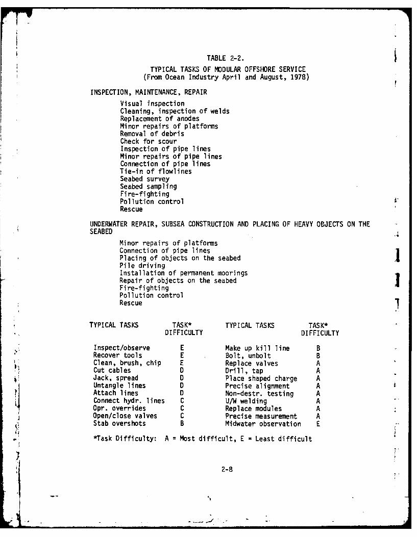
TABLE 2-2.
TYPICAL TASKS OF MODULAR OFFSHORE SERVICE(From Ocean Industry April and August, 1978)
INSPECTION, MAINTENANCE, REPAIR
Visual inspectionCleaning, inspection of weldsReplacement of anodesMinor repairs of platformsRemoval of debrisCheck for scourInspection of pipe linesMinor repairs of pipe linesConnection of pipe linesTie-in of flowlinesSeabed surveySeabed samplingFire-fightingPollution controlRescue
UNDERWATER REPAIR, SUBSEA CONSTRUCTION AND PLACING OF HEAVY OBJECTS ON THESEABED
Minor repairs of platformsConnection of pipe linesPlacing of objects on the seabed IPile drivingInstallation of permanent mooringsRepair of objects on the seabed IFire-fightingPollution controlRescue
TYPICAL TASKS TASK* TYPICAL TASKS TASK*DIFFICULTY DIFFICULTY
Inspect/observe E Make up kill line BRecover tools E Bolt, unbolt BClean, brush, chip E Replace valves ACut cables D Drill, tap AJack, spread D Place shaped charge AUntangle lines D Precise alignment AAttach lines D Non-destr. testing AConnect hydr. lines C U/W welding AOpr. overrides C Replace modules AOpen/close valves C Precise measurement AStab overshots B Midwater observation E
*Task Difficulty: A = Most difficult, E = Least difficult
2-8

(1) Search - survey/locate/observe. The search tasks include
activities associated with the detection and location of
target and lost objects, wrecks, and bottom features; and
the determination of general condition of underwater objects
and immediate environment.
(2) Activation - position/activate/attach. The activation tasks
include such activities as positioning of tools and locating
of detected areas around objects; instrument activation,
active sensing; simple mounting and hook-up.
(3) Travel - pickup/transport/place. The travel tasks include
activities associated with the recovery of small objects,
simple pick-up tasks; moving of objects in a simple trajectory;
and deployment of sensors and instruments.
(4) Clearance - scan/clear/excavate. The clearance tasks include
such activities as NDT; debris clearance; trenching, tunneling,
and dredging, etc.
(5) Assemble/Disassemble - precision measurement/alignment/attach-
ment. The assembly tasks include a whole range of activities
from the measurement of clearance of mating parts or mounting
patch; open/close valve, bolt/unbolt; U/W welding, clamping,
and so on.
(6) Structure Repair - structure monitoring/carrying/assemblying.
The structure repair tasks include activities such as.replacement of valves, modules, and other combinations of4above-mentioned tasks.
2
t I

It appears that the degree of difficulty increases as a specific task
activity moves down this task spectrum. On the other hand, based on a
time-history analysis of underwater diver tasks, the frequency of actually
encountering a specific activity in underwater operation decreases as it
moves down the task spectrum. And it is safe to say that, the easier
the operation, the more frequently it is expected to be performed.
2.2.3 Task Description at Motion Level. A more detailed level of
analysis of a manipulation task can be accomplished by task breakdown
according to either motion function or information requirements. The
formal approach is one of procedure decomposition into finer motiondescriptions, such as the one derived and termed "behavioral elements"
by Pesch, et al. (1970). This latter approach is one of a situationdescription along major spatial or physical dimensions for a specificmotion activity. For a complete description of ataskat this level, itis necessary to include both sequence information, which describes the
order in which motions are performed, and ta.-on information, whichdescribes the conditions under which a given motion is performed.
Considering the problem of selecting a manipulation system in terms of a
specific operation, Pesch, Hill and Kiepser (1970) dissected applied
salvage missions, which included operations such as sample collection,valve manipulation, rigging chain, tapping, threading, drilling, and
connect/disconnect, etc., into five basic behavioral elements: simpletravel, complex travel, simple grasp, alignment and tool use. They
suggested that relative system performance for specific tasks made up ofthese basic elements could be predicted based on the constituent behavioralelements. More comprehensive analyses of behavioral motion elements werelater conducted by other researchers to provide design specification for
special tools in underwater tasks. The following list and examples ofmotion elements and classifications was extracted from Bertsche, et al.
2-10

(1978), Battelle (1976), and Nevin and Whitney (1977) in their study of
the underwater work system and manipulator-operated tools:
(1) Travel - simple trajectory/complex trajectory,
e.g., fetch, return, etc.
(2) Alignment - (a) low precision/high precision,
- (b) no relative motion/with relative motion,
e.g., position, grasp release, contact, etc.
(3) Accommodation - (a) low precision/high precision,- (b) no relative motion/with relative motion
- (c) active force applied/passive compliance,
e.g., insert, rotate, depress, slide,
sea4. etc.(4) Tool use - (a) linear/rotary/special
- (b) steady/impact,
e.g., saw, drill, tapping, hammer, cut, winch,
etc.
Analysis at this level indicates that the major dimensions of taxon informa-
tion can be summarized into three categories: (1) geometric factors,
including distance-depth, orientation, proximity and allowance; (2)
compliance factors, including touch/slippage, force torque, inertia impact,
and compliance stiffness; and (3) temporal configuration, including end-
effector dynamics (speed and acceleration), arm position and access, etc.
Specification and quantification along these dimensions could provide
more rigorous task classification than those existing in the literature
when such a detail analysis is justified by its objective. For the purpose
of this study, we chose to quantify only selected dimensions that were
b critical to man-machine communication. This minimum set of task dimensionswill evolve with the further analyses of the following sections.
2-11

Another aspect of information requirements, the procedure information,
also can be sunmmarized into three categories: (1) motion sequence in
serial operation, (2) motion disjunction/conjunction in parallel operation,
and (3) motion repetition. Related to the procedure information are
planning activities, which will be described in detail in the next sectionand next chapter. Suffice it to say here that a manipulation planning
process, in general, includes not only the task breakdown discussed
above, but also the identification (primitive motion or previously con-
ceived motion procedures) and the reformulation and synthesis (experimenting,
tradeoffs between taxon and procedure information). These last aspects
of manipulation activities have been difficult to analyze, which wasrecognized as "the problem of properly dissecting the overall task." As
indicated by Pasch, et al. (1970), most behavioral elements are not
independent actions that can simply be added end to end to describe a
given task, but rather are attempts to dissect a continuum of independent
activities. Thus, the degree of success for this attempt is related to
the degree of independence of a particular motion on the procedure informa-
tion, a characteristic referred to later as the "discreteness" of a
specific operation. Sunmnarizing the discussions in this section, the
following set of descriptors was considered as the major attributes
characterizing a manipulation operation:
(1) Precision.
(2) Compliance/force.(3) Motion degree-of-freedom.
(4) Discreteness.
&The previous analysis, however, was primarily concerned with intrinsic
characteristics of a manipulation task. In real operation, one has to beconcerned with hazardous environments in underwater operations, in which
environmental impacts on manipulation are more stringent than in controlled
2-12

laboratory or industrial operations. Thus, tasks need to be analyzed
also by the impact of the underwater environment, as will be discussed
in the following section.
2.2.4 Environmental Factors in Underwater Manipulation. The purpose of
environmental factors studies is to examine and identify the important
dimensions that affect the condition and performance of underwater mani-
pulation. The underwater environment imposes conditions of high hydro-
static pressure, dynamic forces from wave and currents, limited visibility,
and low temperature. All of these factors interact to make an everchanging
environment for underwater tasks. Our analysis indicated that among the
physical factors of importance were turbidity, current, and depth (distance).
These factors, in turn, influenced the visibility, stationarity, predicta-
bility and accessibility of the work-space, all critical for successful
operator control.
The deep water environment can be described in terms of a number of
physical properties, as summarized in the Underwater Handbook (Schilling,
et al., 1976). These properties interact to create hostile conditions
for man arnd material. With each additional fathom, these conditions
become more severe for the working diver (Battelle, 1971). In remote
manipulation, some hostile conditions may be alleviated that are related
to immediate support and safety. However, other factors, due to depth,
remain stringent, including those related to vision/sensing (e.g.,
illumination, texture, resolution, etc.), transmission, and resource
constraints. These factors, compounded with time stress, uncertainties,
and potential hazards concerning task operations, create a sense of "remote-
ness" - a psychological distance which increases with physical distance,
and decreases with familitary.
The physical distance poses severe constraints on visibility, and thus
accessibility, in workspace due to the fact that natural illumination,
2-13

[7-
reflectance, and contrast all decrease with depth. Subjective familiarity
is reduced when color and texture of the object become uniform and less
recognizable. Besides, subjective estimates of range and orientation
become difficult in deep water. After considering the effects of depth
along the dimension of physical distance and subjective familiarity,
two other especially important factors in underwater manipulation remain
to be addressed--turbidity and current.
Turbidity of the water depends on the size and concentrations of sus-
pended particles in the water. This characteristic varies from location
to location and typically is the major factor in reducing visibility and
predictability in most underwater environments. The reduction is due to
forward scattering and omni-scattering of light. Effects of turbidity
variations on perceptual performance and display requirements have been
studied by a number of researchers (e.g., Kinney, et al., 1969; Brant,
et al., 1972; Vaughan, et al., 1976, 1977, 1978). In general, the detec-
tion distance was shorter in turbid water than in clear water, and
distance estimates were invariability greater in turbid water than in
clear water. The effect on visibility is of particular importance since
control of present-day underwater manipulators depends almost entirely on Jdirect visual feedback (Busby, 1978; NOSC Ocear, Technology Department,
1978). Experience in laboratory studies and field work has shown that
such devices are virtually impossible to use when vision is degraded by
high turbidity water, compounded by poor angle of view, light failure,
etc. These conditions occur frequently in deep-sea operations, parti-
cularly during bottom work. In fact, visual observation of manipulation
has been a critical factor in machine-to-man communication in almost all
previous experiment work (Smith, et al., 1979).
Like turbidity, the underwater current and hydrodynamic forces depend
also on location. Their main effects can be considered to be on the
I
2-14

stationarity of operation and the predictability of control dynamics.Whil thelater effect can be described as a motion/force disturbance of
the control system, the former one is more complicated and often has to
be considered within the context of moving platform dynamics. Here, the
global consideration of operation stability to compensate for both
external current and reaction forces becomes a major concern. For example,
current flow in the manipulator workspace of up to several knots could
impose rather severe operational constraints in terms of reduced admissible
trajectory volume of the vehicle plus manipulator. Another problem of no
less importance for operator control in this uncertain environment is
the lack of orientation and motion references. The sense of orientation
is a prerequisite to virtually all forms of control, and it is directly
related to the estimate of position and dynamics.
2.3 Operator Activity Analysis
In studying the task analysis of simulated maintenance tasks in our pre-
vious experiments, it was readily apparent that much of the subject's
planning activities were devoted to developing, initiating, and monitor-
ing the subplan. While the subjects usually accepted the overall goaland plan as instructed, the process included the activities of mission
definition, requirement analysis and planning task hierarchy. The parti-
tioning of tasks into subtasks, and subtasks into lesser subtasks, etc.,
was left to the subjects, allowing concurrent lower level planning and
execution (Sacerdoti, 1975; Weissman, 1976). The interface of the
operator function in planning and the supervision of manipulation tasks
is illustrated in Figure 2-2. In the case of a free-swimmiing (unmanned,
remotely-controlled submersible) underwater manipulation, the typical
supervisory control activities of the operator may include the following:
2-15

r7i
TASK HIERARCHYDATABASE PLANNING
BEHAVIORAL *VISUALIZEDDESCRI PTION PROCEDURE
SUBTASKSEQUENCING
MISSION REQUIREMENTS BEHAIRALT EXECUTIO
H AVAILABLE
REQUIREMENTS *CP~N
*EVALUATION
FIGU URE 2.EG) ELETN
OPERATR FUNTION N PLANINGENSUPEVISIO
OF MANIPULATION TASK 1
2-16

(1) Cognition of the environment.
(a) Object, obstacles, seafloor, turbidity, current, etc.
(b) Rate of change of environmental conditions.
(c) Search, detection, localization, identification, and
estimation.
(2) Status apprisement.
(a) Navigation: three-dimensional position relative to
object.
(b) End-effector maneuver: configuration, predicted
trajectory.
(c) Command and control: traded or shared commands,
control rates and modes (resolved motion or joint modes).
(d) Subsystems: capability, limitation, and reserves.
(3) Monitoring
(a) Subtask sequence and completion.
(b) Effector-object interaction.
(c) Geometric relation.
(d) Force-torque tolerances.
(f) Hardware failure and potential hazard.
(4) Execution functions.
(a) Change command and control modes.
(b) Change manipulator configuration.
(c) Begin next phase of subtask operation.
(d) Establish backup mode.
(e) Communicate information.
21
- 2-17
I

(5) Planning procedure and error recovery.
(a) Commiand definition.(b) Sensor deployment.
(c) Subplan editing, geometry editing.
(d) Inspection, manipulation and testing.
The set of supervisory control activities can be grossly classified into
global supervision and interactive control. The former emphasizes situa-tion assessment and the latter emphasizes action implementation.
2.3.1 Supervisory Function Hierarchy. It is considered that in the
supervisory loop, the operator's activity performance can be classifiedinto synthesized categories of overall system performance. As Emery
(1969) has recommirended, the principal test of category inclusion will be
payoff relevance--only categories that discriminate among actions and
that result in actions with differing utilities or performance will be
included. Utilities and performance in this context refer to the follow-
ing dimensions:
(1) Achievement of task goal and operational function.
(2) Time period and expected frequency.
(3) Task operational requirement.
(a) Time.
(b) Accuracy.
(c) Tolerance.
(d) Force.(e) Dexterity.
2-18

(4) Task conditions, as summarized in Figure 2-3, including the
following dimensions:
(a) Intrinsic manipulation characteristics, including those
related to low-level motion constraints (precision,
compliance, motion degrees-of-freedom, etc.), motion
decomposition (discreteness and criticality of motion
elements) and motion sequence (abstractness, struc-
turedness, simultaneity, repetitiveness and variability,
etc.).
(b) System features, including those related to effector
(accuracy, speed, capacity and articulateness, etc.)
and those related to feedback display (resolution,
frame content, time delay, frame rate, and display-
motion compatibility).
(c) Environmental conditions, including those related to
work-space situation (visibility, stability, predict-
ability, and accessibility, etc.) and those related to
ambient conditions (turbidity, current, depth, distance
and familiarity, etc.).
Operator supervisory activities, after previous enumeration of task demands,
information and functional requirements, can be summarized into the follow-
ing three categories:
(1) Situation Apprisement.
(a) Navigation - 4-0 position relative to motion plan.
Wb Guidance -current and predicted trajectory.
2-19

TASK FACTORS
INTRINSIC SYSTEM ENVIRONMENTAL TRAINING ANDMANIPULATION FEATURES CONDITIONS INDIVIDUAL FACTORS
MOTION PROCEDURE FEEDBACK EFFECTOR WORK-SPACE AMBIENTELEMENTS AND ACTIVITIES
PRECISION ABSTRACTNESS RESOLUTION ACCURACY VISIBILITY TURBIDITY ICOMPLIANCE STRUCTUREDNESS CONTENT SPEED S, ABaJ1TY CURRENT
MOTION D.O.F. SIMULTANEITY TIME DELAY CAPACITY PREDICTABILITY DEPTHDISCRETENESS REPETITIVENESS FRAME RATE ARTICULATENESS ACCESSIBILITY DISTANCECRITICALITY VARIABILITY COMPATIBILITY FAMILIARITY
)
FIGURE 2-3.MAJOR DESCRIPTORS OF TELEOPERATOR CONTROL TASKS
2-20

IFF -TWW"w
(c) Control mode - automatic modes and manual modes.
(d) Subsystem - configuration, capability and reserve.
(e) Environment - terrain, weather, traffic (threat).
Mf Clearance - obstacle, threat.
(2) Situation Monitoring.
(a) Subsystem performance tolerances.
(b) Geometric or force tolerances.
(c) Subplan sequencing/completion.
(d) Potential failures/hazards.
(3) Action for Execution.
(a) Change mission phase.
(b) Edit program.
(c) Change arm configuration.
Wd Reduce control accuracy errors.
(e) Commnunicate information.
The list consists of a spectrum of supervisory functions. The top level
of this spectrum represents the demands for multiple channel processingby the operator, and the low level of this spectrum represents the demands
for serial processing, with its associated limited capacity. It is con-tended in this study that the prediction of operator performance in complex
tasks using a remote sensor-based system requires a knowledge of operator
proficiency in the components of the task and an estimation of the infor-
) mation demands by each component.
Accordingly, the information components within specific information typesi4 relevant to the level of supervision hierarchy need to be classified. Atentative set of classifications is given as follows:
2-21

(1) Status/warning.
(2) Quantity.
(3) Comparison.
(4) Time sequence.
(5) Prediction.
(6) Instruction/alternatives.
(7) Feedback.
A useful analysis may lead to the development of a communication matrix
relating information components to display a format such as:
(1) Alarm.
(2) Alphanumeric (text or tabular).
(3) Symbolic/schematic.
(4) Digital.1(5) Dial.
(6) Pictorial.I(7) Perspective.
(8) 3-Dimensional.
2.3.2 Teleoperator Control Task and Information Requirements. Since
vision is the fundamental feedback system for most underwater manipulation .systems, we started our analysis with visual function requirements. The
general visual functions for manipulation tasks were studied and are listed
as follows:
(1) Acuity - degree of detail that can be discriminated or
affected by fixation position and also by illumination and'4 contrast.(2) Size estimation - judgment of absolute and relative size.
(3) Shape discrimination - discerning difference in form.
(4) Brightness discrimination - discerning changes of gray level.
2-22

(5) Recognition of pattern -recognizing image pattern indifferent orientations.
(6) Distancp estimation - estimating distance between offset
targets.
(7) Stereoacuity - size of detail in depth perception.(8) Movement resolution - perceiving movement.
(9) Rate resolution - perceiving rate of movement.
(10) Color Discrimination - discriminating hue, saturation and
brightness.
(11) Frame of reference - resolving operator's coordinate reference
to both platform (manipulator system) and work object system.(12) Zoom reference - resolving dual requirements of both acuity
and range.-
Further analysis and review of relevant documents will provide a useful
crosslist between operator visual functions and visual cue requirements.As a summary of this section, Figure 2-4 presents a list of factors
affecting the quality of visual (scene) information. Some of the factors
were investigated in a simplified environmental feedback experiment, which
is to be discussed in Chapters 4 and 5.
A prerequisite of this analysis was the study of visual information
requirements. A matrix of operator function and relevant visual cueshas been developed which correlates the following two sets of parameters
(Figure 2-5):
(1) Visual cues.
(a) Internal reference.
(b External reference.(c) Perspective.
t (d) Texture.
(e) Motion parallax.
2-23

-1 ~~~ - ; 1-
IPAYGEDPCETO PROCESSING
BACKGROUND FOBJECT/BACKGROUND ENVIRONMENT SENSOR/TRANSMISSION DISPLAY PERCEPTION
Size Depth Signal/Noise Image Resolution Visual AcuityReflectance Ocean/Harbor Band Width Contrast Size Estimation.,lunination Turbidity Format Color Shape DiscriminationContrast Absorption Filtering Brightness Brightness:olor Scattering Spatial Resolution Frame Rate Recognition of Pattern-exture Pattern Backscatter Transducer Resolution Depth of View Estimation of Distanceloti~n Ourstion Frame Rate Monitor Size ConvergenceAngularity rime Delay No. of Monitor Retina ParallaxMarkings Motion Resolution Display Cue Augmentation Motion Parallax
Detection & View Angle Accoimmodation
Frame of Reference PerspectiveSize of Known Object
Light and ShadowInterpositionHaziness of Distance
Detection of MotionRate Estimation
Contrast SharpnessColor & Surface Texture
Frame of Reference
FIGURE 2-4.VISUAL INFORMATION FACTORS
2-24

VISUAL CUES
Nf
4(~4-
DISTANCE TOOBJECT X X X X X X X
LOCATION TOOBJECT X X x X X X X X
AVOIDANCE OFOBSTACLE X X X X X
DIRECTION OFGRIPPER MOTION X x - -
CLOSURE RATE X X X X X X
ALiGNMENT OFGRIPPER X X X X X
GRASP ARRANGEMENT X X X
CARRYING EXTENDEDLOAD X X K x X X X, .
UNLOADING X X X X X X X
LOCATION OFSPATIAL WAY-POINT X x - X X - X
LOCATION OF GRIPPER
TO SPATIAL WAY-POINT X X X X X X X X X X
FIGURE 2-5.'4 MATRIX OF OPERATOR FUNCTION AND RELEVANT VISUAL CUES
2, 2-25
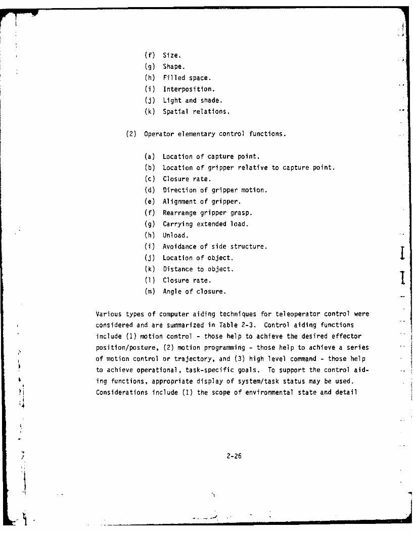
f)Size.(g) Shape.(h) Filled space.
Mi Interposition.
(j) Light and snade.(k) Spatial relations.
(2) Operator elementary control functions.
(a) Location of capture point.
(b) Location of gripper relative to capture point.
(c) Closure rate.
(d) Direction of gripper motion.
(e) Alignment of gripper.
(f) Rearrange gripper grasp.
(g) Carrying extended load.
(h) Unload.
(i) Avoidance of side structure.
(j) Location of object.I(k Distance to object.
(1) Closure rate.1Cm) Angle of closure.
Various types of computer aiding techniques for teleoperator control were
considered and are summarized in Table 2-3. Control aiding functions
include (1) motion control - those help to achieve the desired effector
position/posture, (2) motion programming - those help to achieve a series
of motion control or trajectory, and C3) high level command - those help
to achieve operational, task-specific goals. To support the control aid-b ing functions, appropriate display of system/task status may be used.
Considerations include (1) the scope of environmental state and detail
/ 2-26

TABLE 2-3
TYPES OF COMPUTER-AIDING FOR TELEOPERATORCONTROL/DISPLAY FUNCTIONS
CATEGORY SUBCATEGORY EXAMPLES
1. Control
Control Geometric/dynamic Resolved motion rate control.Motion transformation Resolved motion acceleration control
Effector motion Pre-canned low-level motions, Multi-finger dexterity
Accommodation and Active sensor steering. Passivecompliance compliance
Programming Trajectory repeti- Spatial points. Spatial pathsMotion tion
Trajectory "Reverse problem" solutionsinterpolation
Trajectory Relative (moving-reference)transformation trajectories
Command mix Symbolic vs. Function keys vs. joysticksanalogic
Command Abstraction Multiple-level vs. single-levelStructure
Organization Linear sequential vs. hierarchicalnetwork
2. Display ofSystem/TaskStatus
Display scope Environmental state Spatidl, force, tactile and proximityand level
Machine and program- Control mode and status in parallelming state control
Display Format Display codes Alphanumeric, video TV, graphics
Display inte- Information flow Control of Frame content and updategration rate
b Cue integration Predictor, filtering and enhancement
2-27
ii1I

level of machine and programming state, (2) the display code in use, and
(3) display integration, such as control of information flow and cue
integration. Many of these computer-aiding functions were included in
the task-oriented supervisory control language (TOSCL) developed in this
program. While the design and the evaluation of the language will be
described in the next two chapters, the man-machine interaction aspects
will be discussed in the next two sections.
2.4 Man-Machine Interaction
Recent advances in microelectronics and sensor and processing technologyhave lowered the cost of sensors, processors and communication to a level
where use of unmanned distributed subsystems in the hostile environment,
identifying, localizing, and manipulating moving objects, becomes feasible.
In particular, the concept of having the operator in a remote site, over-
seeing the operations of automated inspection and manipulation platforms,
holds great promise. The use of on-board intelligence in these systems
can, in the foreseeable future, provide "shared man-computer control ."
This concept within the framework of this study implies that the operator
in the commanding site communicates intermittently with the on-board com-
puter, which in turn performs continuous control of the sensors, effects,
and platform subsystems.
Four types of shared man-computer control of remote manipulation areperceived based on the functional relationship for the operator and com-T
puter in controlling the machine. They are (1) augmented (serial) man-
computer control, (2) traded (parallel) man-computer control , (3) multi-
mode supervisory control , and (4) autonomous supervisory control. In
a augmented control (Figure 2-6a), the major computer functions are inter-
preting and transforming control commands received from the operator.
These computer functions include resolved motion control (such as resolved
motion rate control) and steering calculation for active accommodation,
2-28

( HUMAN CONTROLLINGToI MACHINE
OPERATOR COMPUTER
(A)
AUGMENTED (SERIAL)
CONTROL
OPRAO MACHINE
* L= LI OPERATING
COPUER
(8)TRADED (PARALLEL)
CONTROL
--_ COMPUTER1
CONTROLLINGHUMAN IACHINEI
O OCOMPUTER
(C)
MULTI-OE
SUPERVISORY CONTROL
I OPERATING
COMPUTER
HUMAN SUPERVISINGL
OPEPUTRROMCMPUNE
CONTROLLING
COMPUTER
(D)
AUTONOMOUS
CONTROL
FIGURE 2-6.COMMUNICATIONS IN FOUR BASIC FUNCTIONS OFCOMPUTER-AIDED MANIPULATION
2-29

etc. Taxon information constitutes a major portion of operator computer
communication. In traded control (Figure 2-6b), the major computer func-
tions are sequencing and programming the operations of the machine based
on the symbolic command given by the operator. (An example of traded
control is the automatic motion control.) Procedural information con-
stitutes a major portion of opera tor-computer cormnuni cation. A hybrid of
the above two-types of man-computer control is called the multi-mode
supervisory control (Figure 2-6c), in which the computer's operating cap-
abilities and controlling capabilities are aggregated. (Examples are the
variable and chain commands.) Communication based on both taxon and
procedural information needs to be specified between operator and computer.
The most advanced type of shared man-computer control includes the super-
visory and planning capabilities of the computer in performing manipulation
tasks. The autonomous supervisory control (Figure 2-6d) permits the sub-
systems and vehicles to act as an autonomous robot for extended time jperiods. Jointly, the subsystem and the vehicles respond to their environ-
ment in the pursuit of task goals preprogrammed by the operator, andI
possibly updated in an asynchronous communication cycle.
Of the last two types of shared man-computer control, supervisory control1
is seeing increased use in a number of advanced development projects. -
Free-flying and free-swimming robot vehicles are currently being developed
* as microcomputer-controlled sensor platforms (Jet Propulsion Lab, 1979;
Talkington, 1978). On-board intelligence has been demonstrated in pre-
programmed maneuvers, and emergency/abort routines onboard these vehicles.
The development of distributed sensor control in compliance with an art-
ificial arm can be configured with the algorithms of distributed sensor
signal interpretation and automatic generation of motion command (Corker,
et al., 1980). Industrial processes can now be monitored and controlledby decentralized data acquisition and parallel processing. Such fast andintelligent computers can provide sound, well-evaluated decisions with
2-30

potential improvements in reducing system risk, operator workload, and
errors. On this frontier, the operator has to interact with an intelligent
system capable of processing and routing information, executing control
actions, and making choices in view of priority conflicts. The key under-
lying issues are the proper designation of the roles that the human and
the computer are expected to play and suitable interface design for the
specified roles. Related computer-aided interface functions include:
(1) Aggregate sensor data into a communicable format.
(2) Allocate control between the operator and the computer.
(3) Manage the information flow and the communication bandwidth
of the link between the remote operational site and the
control site.
(4) Generate a compatible display of system status and opera-
tional environment.
One major issue concerns man-computer functional allocation. One straight-
forward approach is to allocate a fixed portion of the set of the tasks
to the computer with the remainder of the set being allocated to the human.
Licklider (1960) has proposed that the human sets goals, formulates hypo-
theses, determines criteria, and evaluates results. On the other hand,
the computer should perform routine work such as transforming data, simu-
lating models, and implementing results for the human decision-maker.
However, the division of tasks is not as clear-cut for processing and
decision making tasks that include computerized decision subsystems.
In general, the rules of thumb suggested by many researchers are that man
will handle the very-low-probability situations, and fill in the gaps in
a the problem solution or in the computer program; while the computer may
serve as pattern or statistical inference, decision theory, or game theoryI machine, to perform elementary evaluation, diagnosis, and pattern
2-31

recognition as a second role (e.g., Ramsey, et al., 1979; Vaughan, et al.,
1972; Rouse, 1975; Steeb, et al., 1975; Johnsen, et al., 1978). On the
other hand, many researchers, including Steeb, Weitman and Freedy (1976),
and Chu and Rouse (1979), have suggested that a dynamic or adaptive
allocation of responsibilities may be the best mode of human-computer
interaction. With adaptive allocation, responsibility at any particular
instant will go to the decision maker most able at that moment to perform
the task. Such a scheme is adaptive in the sense that the allocation of
responsibility depends on the state of the system as well as the states
of the decision makers. Thus, changes in system or decision maker states
results in changes in the allocation policy so as to optimize performance.
The policies espoused in these developments are particularly suitable for
implementation in a hierarchical task structure of the procedural net,
as will be described in detail in the next chapter. It is sufficient
here to classify the existing schemes and method of computer-aided inter--
face into four categories: control interface, programming interface,
command interface, and communication automation. The schemes under variousJ
levels of development are listed in Figure 2-7, including those features
incorporated in the task-oriented supervisory command (TOSC) language
developed in this program: multi-mode control, shared multi-programmed,procedural network, and mix-initiative. These will also be discussed in
the following chapters.
Once the task structure and the communication protocol between human and
computer have been established and the status of decision makers and the
system states has been determined, it then becomes possible to dynamically
* allocate functions. The three main reasons for adaptive allocation are:
(1) Efficient utilization ofsse rsucs based on the .theoretical analysis of sytmoeain(e.g., Chu, 1978).
I) 2-32

WvNIPUa.ATY
wWMj.IAYCOYOLLID '4 -XNEMILPU . 310?!3us mI.I Sr 1lR ROBO
...........
O4WIUVISYN CP"CRIAumaN
OWW411 -femi
y PACISS PSTISH
'uucomC SulC
tAL-*EDtE
mOSS A 4 o OL OLTIVEM LOATO LLCTO;L 1.AC "AN" AinTTLM
TXONOM MVOFMNMCIE NTRAE N TELEOERT R COINTROL
"SIA CTV
2-33

(2) Increased flexibility in coping with subsystem malfunctions.
rhe possibility of the computer encountering either a hardware
failure or an event whose decision making requirements exceed
its abilities can never be overestimated. It would seem
reasonable that the human should be allocated at least
monitoring responsibility for all tasks at the top-most hier-
archy level (e.g., Moray, 1976). On the other hand, if
tasks are strictly allocated, the human would not know or
attend to those operations under the computer's supervision
until abnormal situations developed and placed still higher
demands on the human to explore and control the subsystems.
(3) Effective role assignment to the human. The adaptive policy
potentially assures the human a coherent role in that the
considerations of operator load and style are taken into
account (Steeb, et al., 1979).
The potential advantages of the supervisory control over a direct manual1
or a standalone automatic control include:
(1) Increased flexibility and dexterity in mission performance--
achieved through the operator in the supervisory loop.
(2) Increased reliability and, for certain tasks, precision--
achieved through system modularity, redundancy provided by
supervisory loop, and extended subsystem capability.
(3) Less susceptable to failure and communication channel break-down--due to confident autonomy in subsystems allowing
intermittent communication with reduced bandwidth requirements.
2-34
'.1
(4) Great efficiency and lower communication cost when communi-cation is extremely bandlimited or imposes a time delay--due to enhanced real-time response, parallelism in processingand allowed data/command compression in transmission.
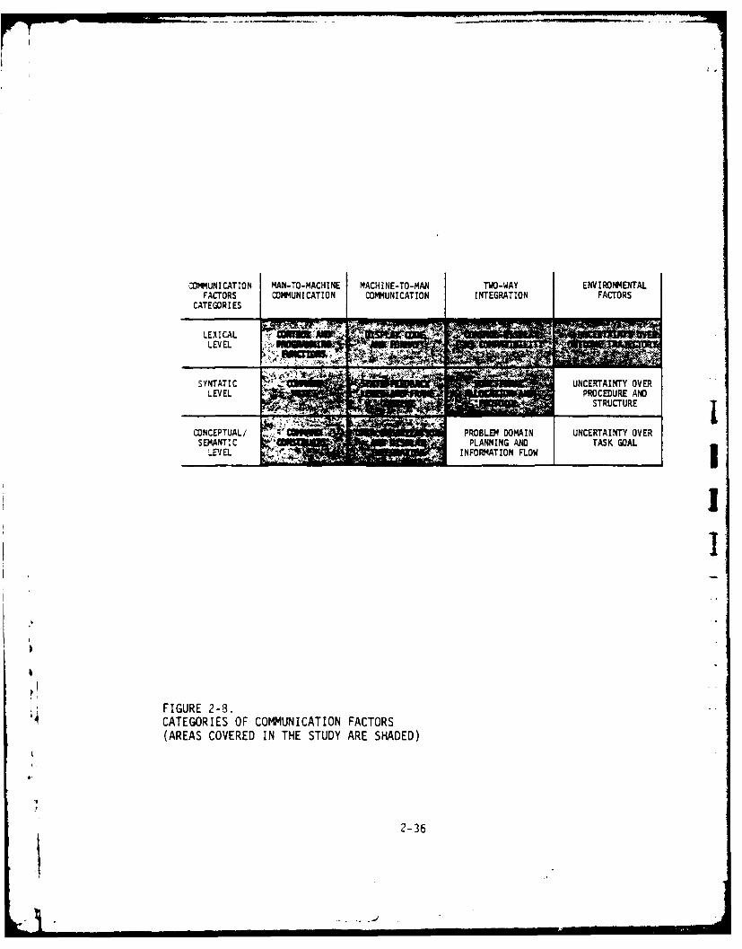
In this context, the current program sought to identify and evaluateimportant man-machine communication factors, and can be considered as afirst step toward the realization of those advantages in the use ofsupervisory control. For the convenience of evaluation, categories ofcommunication factors were identified in the design process. They arelisted in Figure 2-8, with areas covered in the studies shaded. Man-machine communication requirements within these categories were analyzedand evaluated and the results are reported In Chapter 3 and Chapter 4,respectively.
2-35
COMMUNICATION MAN-TO-MACHINE MACHINE-TO-MAN TWO-WAY ENVIRONMENTALFACTORS COMMUNICATION COMMUNICATION I NTEGRATION FACTORSCATE GOR IES
LEVEL _14°
'A'
SYNTATIC " UNCERANTY OVERLEIEL t;PROCEDURE AND
STRUCTURE
CONCEPTUAL/ ;'PROBLEM DOMAIN UNCERTAINTY OVER
LEV EL - I NFORMATION FLOW
)!
II
FIGURE 2-8.CATEGORIES OF COMMUNICATION FACTORS(AREAS COVERED IN THE STUDY ARE SHADED)
I
2-36I!:L |

3. TASK-ORIENTED SUPERVISORY CONTROL SYSTEM METHODOLOGY
3.1 Overview
As we extend shared control of a manipulator system to the full range of
capabilities afforded by the computer element, the question of man-computer
conmmunication becomes of primary importance. Many of the previous studies
(e.g., McGovern, 1974; Whitney, et al, 1977) advocated the shared man-
computer control. Only sketchy attention, however, has been devoted to
the analysis and design for effective man-machine communication in the
task-oriented supervisory control paradigm. This chapter describes an
attempt at Perceptronics to develop a model for the man-machine commnuni-
cation process, to derive principles for language design, and to implement
a command language and associatd interface. The effectiveness of this
approach was experimentally tested and the results are to be discussed in
the next chapter.
Previous work in manipulator command language has been largely concentrated
in two approaches. In the "programming approach," exemplified by Ambler,
et al (1973), Lozano-Pere.- (1977), Finkel, et a] (1974), and Paul (1979),
the manipulator is controlled by a program-like command language which
~-equires prolonged programming and debugging for any specific task. In
addiiton, the environment is presumable predetermined and tightly con-
trolled, prohibiting the use of such a system in novel environments. In
the "direct control" approach, exemplified by the master-slave system of
Goertz (1954) and the submersible manipulators used by Pesch, et al (1971),
continuous on-line attention of the human operator is required and advan-
tage is not taken of the computer capability for control assistance.
The approach of this study falls in a third category called "shared
man-computer control" by Freedy (1973) or "supervisory control" by'4 Ferrell (1965). A procedural net planning concept of Sacerdoti (1975)
3-1

was used as a model of the man-machine communication process on the con-
ceptual level. This model suggests a language with the structure of
defining new commands as "chains" of more primitive commands. On the
syntactic level, previous work in man-machine dialogue (e.g., Foley and
Wallace 1974) suggests that commands should have the form of separate
sentences, each specifying a complete task, and that the communication
process should have conceptual, visual, and tactile continuity. The
language developed in this study follows the following principles: (1)
communicate using complete concepts specific to the task at hand, (2)
allow for on-line real-time adaptation to specific situations, and (3)
allow communication at the level of detail most comfortable to the user.
The language so designed is limited in that spatial points and trajectories
have to be defined before they can be addressed, and in that the computer
does not employ any model of the external world, as would be useful in
correcting errors, automatic planning of motions, and updating subtask
goals, etc.
Nevertheless, using this representation, a problem domain can be described
as a hierarchy of procedural nets, each representing some task in the
problem domain in terms of its goal, its component subtasks, and their
relation to the environment. This information is represented as a
combination of data structures and procedural information in the procedur-
al net. Sacerdoti used this model as a formalism to represent complex
manipulation tasks which is useful for planning and problem solving. This
study hypothesizes that the adapted model is compatible with the human
perception of a complex task, and can serve as a medium for communication
of such a task between an operator and a manipulative mechanism. Using
bthis model as a base we derived principles for language organization,
command features and communication protocol implementation. The model,
further, makes clear the role of the human operator in the supervisory
control approach to manipulator control, and also clarifies the functions
3
1 3-2

that should be performed by an assisting computer placed in the control
and monitoring loop.
3.2 Background
3.2.1 General. The related areas of research to be addressed include
human-computer interaction, human factors in interactive systems, commandI
language in general , and manipulative command and feedback systems in
particular. Relevant principles have been derived from the related
literature to guide the design of the TOSC system and the exploration
of the most effective command/display modes. These principles, described
in the next section, are organized as follows:
(1) Preliminary principles of command language design.
(a) Use task and concept oriented commands.
(b) Use hierarchical command organization.
(c) Allow for mixed initiative.
(d) Provide concept definition capability.(e) Use constrained, standardized language.(f) Provide for tactile, visual and contextual continuity.
(g) Any error can be undone.
(h) Simplicity.
(2) Preliminary principles of feedback display design.
(a) Provide feedback on system state.
(b) Consistent structure of command and feedback.
(c) Provide proportional effect and optimal scaling.
(d) Provide spatial , movement, conceptual , and task
compatibility.
(e) Provide display integration of information channel.
3-3

3.2.2 Preliminary Principles of Command Language Design.
(1) Use Task and Concept Oriented Conmands. This is related
to the idea of making the system compatible with the user's
concept of the problem domain. The human operator thinks
in terms of tasks and complete concepts and these are the
basic units in his language. Organizing the command
language around such units provides a natural mental frame-
work for the user, allowing him to think about the task at
hand, rather than the mechanics of expressing his intentionsin terms of manipulator orientation and joint motions. As
Bennett (1972) has written in an excellent review on The
User Interface in Interactive Systems, "Software designers
have been justly criticized for providing tools that forceusers to behave in nonproductive modes. While designers
have been correct in foreseeing new modes, either they did
not anticipate new patterns accurately (poor design), or
they did not effectively transfer the user's mind to the
conceptual framework that guided the design (poor training).
In any event, the impact on system performance of the user's
concept of the tool is too important to be left to chance."
(2) Use Hierarchical Task organization. As argued by Oijkstra
(1972), and the structured programming discipline, such
hierarchical , systematic structuring is essential for
producing large, error-free programs. We believe that thisprinciple carries over in other communication environments
such as the language for real-time communication with a
general-purpose manipulator. The language should have
facilities to define a task in terms of its subtasks. The
user will be able to express his intentions at a comfortable
3-4

level of plan detail . On one hand, giving commands in too
much detail would cause the user to lose sight of the over-
all task while dealing with the details. On the other hand,giving a command at a gross level does not allow adaptation
of the command to the peculiarities of the situation at
hand. The communication should take place at the highest
symbolic level comfortable to the user and he should havethe facility to choose this level. There are, however,
cases where it is necessary for an operator to manuallycontrol the manipulator motion, e.g., for fine adjustment,and a manual "back-up" facility should be incorporated intothe hierarchical system.
(3) Use Sentence Structure. "Communication should be carried
out in a terse 'Natural' language, avoiding the use of
mnemonics. Abbreviation should be allowed wherever possi-
ble," (Kennedy, 1974). Foley and Wallace (1975) suggested
that the commands in a language should be task-or-concept-
oriented and should have sentence structure. That is: "An
action language is sentence structured if, within a givenphase or subdomain of discourse, each complete user-thoughtcan be expressed in a continuous sentence of input devicemanipulations with standard patterns of beginning and termi-nation. Upon termination, the machine returns to a statefrom which similar action sequences, other sentences, canbegin." The structure is enhanced if the verb-noun format
of natural language is utilized. Treu (1975) calls the
essence of a command an "action primitive" and suggests
a specific structure to each command: "(1) action verb;(2) action qualifier(s); (3) object(s) of action; (4) ob-
ject qualifier(s)."
3-5

(4) Allow for Mixed Initiative. In the task of controlling a
manipulator, some functions are performed better by the Ihuman operator and some are done better by the on-linecomputer. Allowing easy transfer of control from one tothe other with initiative going to the best performer in
each subtask should improve overall performance. In a
hierarchically organized system, mixed initiative is
relatively easy to incorporate.Jj
(5) Provide Concept Definition Capability. In natural language
we use pre-defined concepts and the perceptual capability
of the listener to refer to the objects and actions in the
environment. The current state-of-the-art in machine per-ception does not allow references to points or paths in
space using objects in the environment. It is necessaryI
to bring the manipulator to the specific point or to movethrough a path in order to define them for the computer.
Using coordinates in a dynamic situation presents difficultybecause of human distance estimation errors.
Additional principles derived from work in related areas of Iman/machine communication were also incorporated into thelanguage and interface design. These related areas include:
man/machine "conversation" about graphic data (Foley and 'Wallace, 1974); man-display mechanisms (Engel and Granda,
1975); and others in human factors engineering design. i(6) Use Constrained Standardized Language. As shown by Ferrell [
i 14 (1973), an artificial, constrained, and standardized language
facilitates performance in manipulative tasks better than a jfree-format, English-like language. The advantage comes from
3-6 :

the fact that, although entire manipulation task goals are
readily and perhaps most easily described by a person using
ordinary English, the complex geometrical and temporary
configurations of objects and motions are not readily formu-
lated in such a way. A structured but flexible, task-orient-
ed, artificial command language can enable the operator to
work more efficiently as well as simplify the process of
machine translation.
(7) Provide for Tactile, Visual and Contextual Continuity.
Foley and Wallace (1974) also emphasize the importance of
continuity in the operator sensory and comceptual interac-
tion with the system. Tactile continuity refers to natural
grouping and flow of motion required for the tactile input
devices such as keyboards, joysticks, etc. Visual continui-
ty refers to the arrangement of information, so that within
a given sentence, (i.e., one conceptual command), the eye
should focus on a single area on the control panel or move
in a continuous manner throughout the expression of the
sentence. Contextual continuity refers to providing
immediately perceivable responses and giving standard feed-
back information in dedicated, fixed positions in the
visual field.
(8) .4ny. Error C'an Be Undone. Human operators, especially under
time pressure are error prone. A system accepting operator
commands must have easy "error recovery capability." Engel
and Granda (1975) see this as an important feature of any
computer command language. Kennedy (1974) states: "Each
entry should be short so that errors can be corrected
simply and a reasonable tempo can be established." However,
3-7

"verbose error messages should be avoided for the sophisti-
cated user.. .and he should have a facility for suppressing
long error messages."
(9) Simplicity. To facilitate training and ease the memory
burden on users the language must be simple. This precludes
all kinds of fancy features that regular programming
languages are replete with, such as loops, conditional
statements and logical relations. Falkoff and Iverson
(1973), while describing the design of APL, suggest addi-
tionally, simplicity and practicality as the general
guidelines they used in the development of APL. In parti-
cular, "...Simplicity enters in four guises: Uniformity--
rules are few and simple; generality--a small number of
general functions provide as special cases a host of more
specialized functions; familiarity--familiar symbols and ,
usage are adopted whenever possible (this is also, in part,
'task oriented'); and brevity--economy of expression is jsought." IAdditional principles indicated by Kennedy are:
Control: "Control over all aspects of the system must
appear to belong to the user."
Redundancy: "Redundancy in the dialogue should be avoided
or reduced, especially as the user becomes more familiar
with the system."
Adaptibility: "The system should adapt to the ability of
the user."
'3
4,
'7,! 3-8

Communication Rate: "The rate of exchange must be within
the user's stress-free working range. Control of the rate
should always appear to belong to the user."
A conscious attempt was made to incorporate as many principles as possible
into the manipulator language design. A natural procedure is to go through
a top-down, three-level consideration: conceptual/semantic level, syntac-
tic level, and lexical level. The conceptual/semantic level refers to the
fundamental approaches such as task-oriented or program oriented, sequen-
tial or hierarchical network. The syntactic level refers to the language
structure, such as command sequence and command-operand order. At the
lexical level, words of the action elements are related to the elementary
hardware/software functions represented by an analogic or a fixed symbolic
command word. The procedure is to be described in Section 3.4.
3.2.3 Preliminary Principles of Feedback Display Design.
(1) Provide Feeadback on System State. In dealing with man-
machine display interfaces, Engel and Granda (1975)
emphasize the importance of providing continuous feedback
to the user about the state of the computer system he is
dealing with. The information alleviates the frustration
generated in the operator when dealing with a complex
black box.
(2) consistent Structure of Language and Feedback. Language
structure refers to the external formats of the commands
in the language. Feedback structure refers here to the
format of the information about the system state presented
b to the operator. Consistent structure reduces training
time, error rate, and user memory requirements and is a
3-9

basic feature of a command language. It is related to
Foley's and Wallace's (1975) idea of sentence structure.
(3) Provide Proportional Effect and Optimal Scaling. Propor-
tional effect refers to a monotonic, analog visual form
of geometric or sensor information. Optimal scaling refers
to appropriate level of precision/resolution in displayed
(task or environment) information (McCormick, 1970). High
resolution sensor information is expensive to obtain in an
operational environment, and much of the critical informa-
tion for operator under shared man-computer control can be
extracted from data of low frequency and reasonable resolu-
tion.
(4) Provide Spatial, Movement, Conceptual, and Task Compati-
biLity. Spatial compatibility refers to the physical
features and arrangement in space of the parts of the Jdisplay (McCormick, 1970). Movement compatibility refers
to the relationships among the directions of the movement
of the displays, controls, and system responses (Chapanis,
1965). Conceptual compatibility is based on the as.ocia-
tion of user's intuitive understanding and the display .1
code representation. Task compatibility reFprs to display iinformation relevance and the format related to the A
desired perceptual task (Schutz, 1961). Whenever possible,
related information should be presented in a common display
to expedite visually encoding the data with the least effort
(Roscoe, 1968). This relates to the aesthetic aspect of 71
display integration, which refers to the coordination ofthe display components so as to minimize both interference
and scanning effort. In general, compatibility is achieved
3-10

when "the ensemble of stimulus and response combinations
comprising the task results in a high rate of information
transfer" (Fitts and Seeger, 1953).
(5) Provide Display Integration of Information Channels. In
multiple-task display integration, issues of consideration
include minimized visual (attention) competition, conformed
scan pattern, clarity of form, and disciplined prompting
(Ashford, 1969). Priority of the display parts may be
derived by appropriate features such as relative size,
order, intensity, contrast color, and textures, etc. In
multiple-source display integration, issues of consideration
include the choice of effective feedback modality, resolution
and format of the presentation, and the gating of the infor-
mation. Bejczy (1977), in an exploratory study of displays
for supervisory control of manipulators, proposed a design
process of (a) selection of a proper type of display; (b)
selection of a proper format for a given type of display so
that the display presents all necessary information in a
timely manner and in a form easily perceived by the opera-
tor; and (c) integration or integrated display of visual
and non-visual sensor information.
In a shared man-computer control paradigm, it appears that complete feed-
back of system and task status includes information concerning: (1)
machine status--manipulator and subsystem functions, (2) program state--
commands defined and mode in execution, (3) task in progress--current
activity and criteria, (4) environmental state--workspace and environ-
mental data. A three-level, top-down organization of display feedback
design is perceived: (1) display system level--sensory modality, display
device and quality, (2) data structuring/processing level--frame content,
3-11
frame rate and bandwidth, etc., and (3) coding presentation level--
geometric primitives, symbol and cue considerations.
3.3 Man-Machine Communication Models
3.3.1 Background. A model is a representation of some part of the real
world which is useful in understanding the important variables relevant
to some problem, and the structural or quantitative relationships among
such variables. Models considered are the ones used to describe observ-
able events and relations among measurables of the communication processes.
They may be descriptive if they intend to portray the external behavior or
internal mechanism of the process. Or they may be normative when desirable,
rather than actual, behavioral action is prescribed. Usually, a much more
extensive knowledge about the modeled system is needed to provide a
successful normative model. The objective here is a modest one, i.e.,
to develop a structure-descriptive model of a communication process which
could bridge the conceptual level and syntactic level of process descrip-tion.
For a shared man-computer manipulator control system, many models areJ
needed to address different aspects of the system functions. In the
lower level of manipulation, models are developed to describe the staticJ
dynamic behavior of the manipulator. The work of Paul (1971), who built
a dynamic model of the manipulator at Stanford, is an example of a model
using a rigid body model of each manipulator segment. The differential
equations obtained were used to predict forces and trajectories of the
manipulator parts under different loads. At a higher level, at the
human-task interface, a model can be used to predict time and accuracy
of motions. Fitts (1954), using information theory tecnniques, showedhow a logarithmic measure of the ratio of distance of movement to the
allowed error tolerance was a simple but useful predictor of move time.
3-12

This logarithmic measure became known as "Fitts' index of motion diffi-
culty." Hill (1976) extended this analysis to movement with a manipula-
tor and made extensive measures of time to completion with different
manipulators and tasks with a varying number of degrees of freedom. He
concluded that the Fitts index had to be substantially modified for tasks
with differing constraints.
On the other end of the development are the machine intelligence models
which have broadened the scope of communication problems to include the
following: (1) specification of goal and subgoal, (2) cognition of the
environment, (3) problem solving (on an abstract level), (4) planning of
solution, (5) execution and monitoring of the plan, and (6) procedures
for error recovery. All these problem areas have been continuously
attacked by Artificial Intelligence researches. Although completely
automated, general-purpose manipulation and problem solving are a long
way from reality, these models provide useful directions in formulating
communication models of advanced man-machine systems.
The most practical approach attempts to develop higher and higher command
languages, ultimately reaching the point where the commands will specify
complete tasks. For example, Lozano-Perez and Winston (1977) describe
LAMA, a high level command language at M.I.T. It solves the problem of
object collision avoidance by brute force--requiring extensive three-
dimensional modeling of all objects in the work area. This system is,
thus, an attempt at solving problems 1, 2, 3, and 4 above. Ambler, et al,
(1973) describes a similar computer controlled assembly system. This
system was unique in that it could recognize the parts it needs from a
randomly dumped heap of parts. It would take the heap apart, put the
parts in order, and proceed to assemble them by feel, according to a
prepared assembly program. It can be instructed to perform a new task
with different parts by spending an hour "showing" it the parts, and a
3-13

day or two programming the assembly manipulations. Amber's system is,
thus, a promising attempt at all the six problems previously stated, but
at the current state it requires extensive control of the environment in
terms of lighting and background and pre-knowledge of all parts in the
heap.
Fike and Nilsson's (1970) STRIPS is an example of a symbolic problem
solver that attempted to solve robot location problems in a simple
environment. It worked well only on simple problems (in terms of the
number of operators required in the solution), and Sacerdoti's
(1975) ABSTRIPS achieved some success in pushing the complexity barrier
by solving the problem in a hierarchy of abstract spaces. Fahlam (1974)
describes a problem solving system for block manipulation which demonstra-
ted high solving power for this idealized world of blocks. The key words,
however, are idealized and abstract. These problem solvers cannot, at
this state, handle the complexity of real world objects in terms of
shape, position relations and function.
More recently, the focus of automatic problem solving/planning has been
directed to the representation of knowledge for the particular problem
domains (Sacerdoti, 1979) and to the distributed problem solving (Lesser
and Corkill, 1979). Possible advantage may be obtained with the use of
models and developments of distributed sensor, control, and decision in
advanced manipulation (Lyman, et al, 1979; Corkill, 1980). Also, the
representation mechanism developed in this area can be adapted to serve
as a model for the man-machine communication environment. Thus, a more
detailed description of the structure and function of one of the devel-
opments, Sacerdoti's procedural nets (1975), is warranted here.
k 4The procedural nets (PN) is the formalism in which tasks are represented
in the system. It is hierarchical data structure containing both declara-
31
'i 3-14
-I. -.

[7".
tive and procedural, domain-specific knowledge. The declarative part
contains the preconditions necessary for an action to be applicable and
the result or the effects of the action on the environment (as in STRIPS,
Fikes and Nilsson, 1971). The procedural part indicates how this parti-
cular task can be achieved in terms of a more detailed, partially ordered,
set of actions. When the system uses this representation to advise an
apprentice, it develops (plans) a description of the task to be performed
from the top level down. It starts with a general statement of the task
and expands it hierarchically in successive levels of more detailed
descriptions to the level of details that the apprentice can perform as
single conceptual units. If he does not know how to do some subtask at
the level of detail given, the computer can develop the node in the
procedural net associated with this subtask into a sequence of more
detailed subtasks. The declaration information in each node is used in
the problem solving part of the process. The system uses it to develop
a plan that will achieve the stated goal without internal conflicts,
starting from the initial state of the world.
The essential aspects of procedural nets relevant to our problem are:
the top-down hierarchical representation of tasks; and the fact that the
conceptual units communicated between the system and the user are complete
tasks at various levels of details. This is contrasted with other systems
which dealt only with sets of primitive manipulator motions. Although
this system deals with a computer supervisor and a human operator, while
we are dealing with the inverted role-play of a human supervisor and a
computer-controlled manipulator, the issues of planning, problem solving
and communication are similar.
3.3.2 Adapted Procedure Nets Framework. The procedure nets model
A discussed above suggests a basic structure for the design of man-machinecommunication. In the NOAH system, the PN is used for task description
3-15

and as a machine advisor for an apprentice. Thus, the PN are developed
hierarchically, by the machine from the top down to the level of details
that the apprentice can perform directly. This development is hierarchi-
cal in the sense that it can be developed to different levels of details
for different parts of the task depending on the level of knowledge of
the apprentice about the particular subtask at hand.
In a shared man-computer control paradigm, however, the role of operator
and systems need to be redefined. The level at which the man-machine
interface occurs determines what was termed the "communication mode"
(Verplank, 1967). Figure 3-1 shows some examples of possible placements
of the man-machine interface (Sheridan and Verplank, 1978), which is one
of the main language design decisions. If it is placed at a very low
level, as shown in Figure 3-lA, where the operator controls joysticks
which cause link movements, then we have "direct control" and a computer
is actually unnecessary. If the communication is done at a very high
level, shown in Figure 3-1B, then we have "symbolic control," or, consi-
dering the fact that in this case a computer does a large part of theplan development and monitoring, this is sometimes called "automatic
control ." In controlling a general purpose manipulator, either control
mode alone cannot be sufficient. As Verplank (1967) has shown, both
analogic and symbolic commands are necessary for effect,ve communication.
Some tasks, those completely pre-specified, can better be called by a
symbolic command, and others, those involving complex geometric motions
that are not repeated, can better be specified by direct control . This
is shown in Figure 3-iC. Figure 3-1D considers the situation when man
sets up the goal at the top level , computer plots the strategy, and the
actual execution is again given to the man. This control allocation is
the one adopted in NOAH where the computer knows how to perform a set
A of tasks, the human apprentice sets the goal , and then requests from the
computer the detailed plan (sequence of actions) that will accomplish
3-16

TASK HIERARCHIES
MAN MACHINE
D"IRECT I"AUTOMATICICONTROL" CONTROL"
" SYMBOLICI COMMANDS"
I ANALOGICICOMMANDS"
k(A) (B)
SYMBOLCCOMMANDS
I-SUPERVISORY I COMPUTERCONTROL" STRATEGY
ANALOGI HUMANANALGIC ~ IACTIONM
COMMANDS E
(C) (0)
A FIGURE 3-1.
ALTERNATIVE TASK HIERARCHIES SHOW THE ',EED FOR ALTERNATIVECOMMUNICATION MODES (SHERIDAN AND VERPLANK, 1978).
3-17

the goal. He then goes ahead and executes the actions himself. This
discussion shows the flexibility needed in the communication model in
describing control allocation strategies.
The proposed task model treats an overall manipulation task as a network-
like structure, with individual manipulator-environment interaction com-
bined into subtasks, which are then combined into one overall task. Each
node of the network structure consists of (I) a goal statement--what must
be accomplished by the task, identified by a command or a named chain and
a set of completion criteria, and (2) an action--the sequence of subtasks,
expressed as lower level of the network structure, identified by the
content of the command or chain. This information is represented as a
planning procedure in each node of the network. The planning process is
activated when a global task request is made at the node in question.
The activation initiates the procedures within the selected node, evalu-
ates the current state of the environment and then activates an appro-
priate sequence and control allocation of subtasks which, when accomplished
one after another, by operator or computer or both, will satisfy the goal.
These subtasks are then activated and the procedures within each respective
nodes are, in turn, developed into a plan of finer levels of detail.
Figure 3-2 illustrates the representation of the task "Shut Valve." At
the conceptual level, the task and command description is independent of
valve type and valve location and the parameter that is needed at this
level is an indication of the type of operation and which valve is operated
on. One level lower in the task, "Approach-Grasp-Shut," the valve location
and geometry is needed. At the level underneath it, a specific control
mode and configuration has to be decided.
This representation of task depicts flexible role assigned between operator
and machine. The operator conceives the task at a high level of ab'trac-
3-18
• .oJ -I
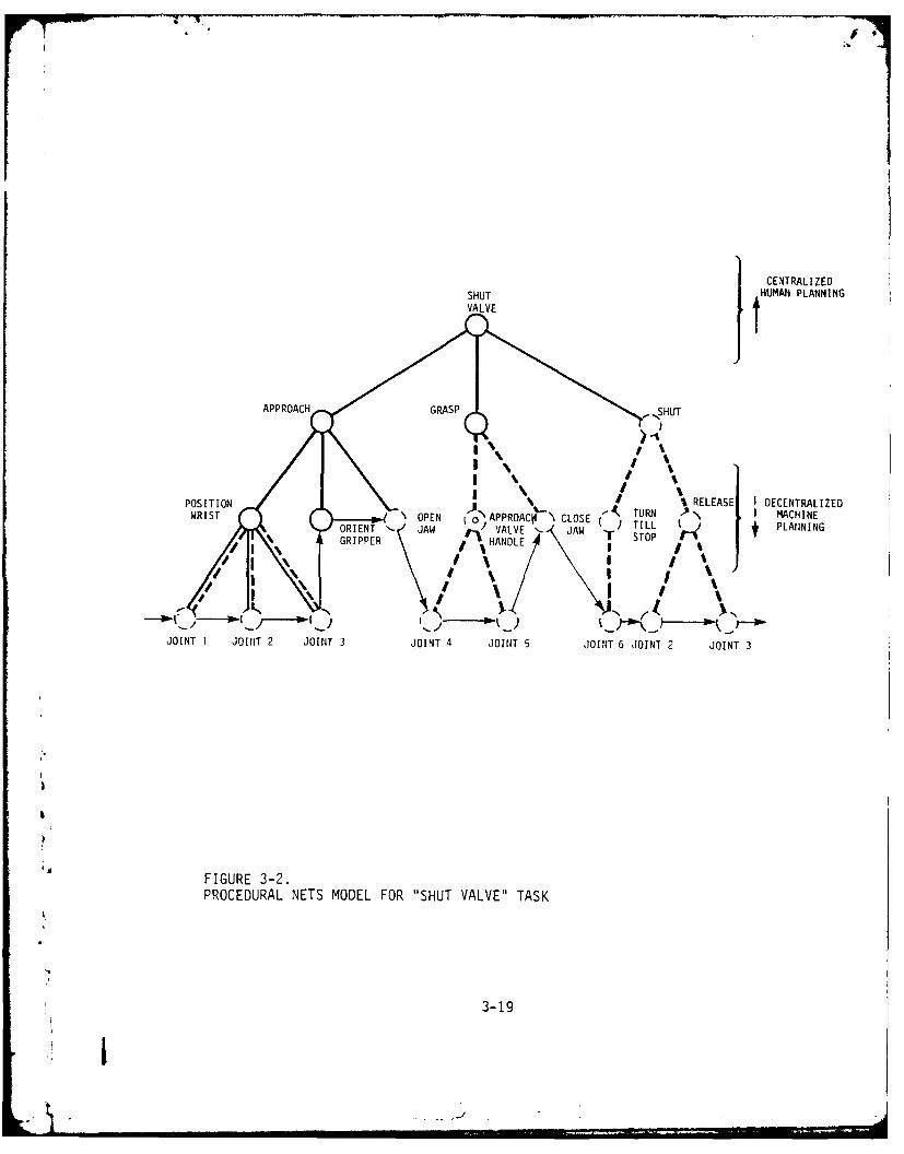
1CEN~TRALIZEDSHUT JHUMAll PLANNING
POSTIO RELEASE I DECENTRALIZED
GRIPERT JA VALVE '- JAW TILL J PLANIN INGGRIPPER HANDLE SO
JOINT 1 JOINT 2 JOINT 3 JOINT 4 JOINT 5 JOINT 6 JOINT 2 JOINT 3
A FIGURE 3-2.PROCEDURAL NETS MODEL FOR "SHUT VALVE" TASK
3-19
tion and develops it to some intermediate level, where the machine (coin-
puter) can accept. He communicates this intermediate-level plan, which
is shown in the figure as the tip-nodes of solid lines, to the computer.
The computer, having previously stored the description of each subtask
at that level , develops the plan to the level of primitive actions which,
as represented in dotted nodes in Figure 3-2, can be communicated directly
to the manipulator. The arrows connecting the tips of the procedural nets
are the sequencing links between the manipulator primitive action, as
observable in a task/environmental display.
The procedural net model suggests a basic structure for the communication
language and feedback design. It is a task-oriented command and feedbackwith provisions to define task and to receive feedback information at
suitable levels of complexity. Figure 3-3 illustrates the levels of detail
information required for adequate indication of subtask state. The repre--
sentation also provides multiple level-of-detail description of sub-goalachievement; and each node up the hierarchy requires broader field of view
and lower resolution. This common structure of command and feedback notonly greatly increases the ease of implementation but also provide grosscorrespondence between command range and spatial geometry hierarchy.
3.4 Syntactic Analysis of the Task-Oriented Supervisory Command Language
This section describes syntactic and lexical elements of the language
along with the keyboard arrangement, feedback display, and the dynamics
of the interactions. In Section 3.4.1 we discuss the two types of com-
mands which make up the language: analog commands to specify detailed
motions or points in space, and symbolic commands to direct the manipula-
tor to do some primitive or structured task. Section 3.4.2 describes theA keyboard and joystick interfaces through which the commands are activated
and transmitted to the machine. The form and arrangement of the keyboard
3-20

"SHUT VALVE" STATUS
FEEDBACK
D ISPLAY
"APPROACH" "GPOS"SUO"
POSITION PSTO TT
,L URN Ct4PLETION?]
I.TASK/I ENV IRONMEN~T
DISPLAY
"4 FIGURE 3-3.INFORMATION FEEDBACK REQUIREMENT FOR "SHUT VALVE" TASK
3-21

are strongly related to the syntax and commands of the language. The
keyboard arrangement is designed for visual and tactile continuity and
for a physical realization of "sentence structure." Section 3.4.3
describes the language primitive concepts and lexical elements from points
and paths to primitive motions and actions. Section 3.4.4 covers the
hierarchical structuring capabilities of the language--namely chains.
This capability allows on-line, real-time construction of automated
subtask tailored by the user to the specific task at hand. Finally,
Section 3.4.5 summarizes the command language features and characteristics.
3.4.1 Analog Versus Symbolic Commands. A basic feature of the manipula-
tor command language is the capability of specifying by analog inputs
points and paths in link space. The analog commands are complementary
to the symbolic commands that comprise most of the command language. The
symbolic commands are the subject of the rest of the sections in this
chapter. The physical interfaces that provide these analog inputs are
two three-degrees-of-freedom joysticks. The assignment of joysticks
variables to arm motions have two modes that can be selected by the user,
the "joints control" mode, and the "spatial control" (RMRC) mode.
In "joints control" each joystick variable is assigned to a specific
aanipulator link. The right joystick is assigned to the upper three
links: shoulder rotate, shoulder raise and elbow flex. The left joy-
stick is assigned to the lower three links: elbow rotate, wrist flex
and wrist rotate. Figure 3-4A shows these control assignments. The
operator's right hand is doing the major manipulator moves and the left
hand is doing the final gripper orientation. Through previous experience
it was found that the direct control mode is useful in subtasks where a
particular manipulator configuration is sought (such as in stowing the
manipulator) or a particular orientation of the gripper is needed.
3-22

8(4
RIGHT JOYSTICK
e6 6
LEFT JOYSTICK
(A) DIRECT RATE CONTROL
RIGHT JOYSTICK856
36
LEFI JOYSTICK
(B) RESOLVED MOTION RATE CONTROL
FIGURE 3-4.JOYSTICK MOVEMENTS AND CORRESPONDING MANIPULATOR MOVEMENTS
3-23

• #.
In "spatial control" mode the variables of the right-hand joysticks are
assigned to control the motions of the wrist in the x1 , x2, x3 cartesian
space. The assignment is made to be as natural as possible: right-left
(x1 ) motions are controlled by the right-left joystick variable; forward-
backward (x3) are controlled by pushing the joystick away or toward the
operator; and up-down (x2) motions are controlled by rotating the right
joystick. The allociations of the left joystick variables are not
changed. Fibure 3-4B shows these control assignments of the two joysticks.
Experimental results indicated that this control mode is useful for most
general motions in the manipulator's work space--like moving around an
obstacle on the way to the tool-box. Experiments done in the past
further showed that both control modes were necessary. The command to
shift control between the joint control and the spatial control modes is
given by the following key sequence:
SPATIAL JOINT CONTROL DO
One of these two control modes is always active, and the activation
command switches between the two. The joysticks are rate controls and
have a small nonactive zone around the spring loaded zero point. When
they are moved out of this small area they cause motions as described
above. Manipulator motions can be caused by either pure analog commands
or by superimposed analog and symbolic commands. This "live joystick"
feature allows real time small corrections to be done by the operator
while the manipulator is controlled by the computer to perform some
automatic task.)
3.4.2 Keyboard Arrangement and Feedback Format
'A The close relation between the command language and the features of the
keyboard and feedback-display-screen require a description of the keyboard
3-24

arrangement and the feedback format. A special function keyboard was
designed and built to optimize speed and smoothness of interaction betweenthe operator and the system in sequence-structured commands. That is, all
commands are intended to have a consistent form of a sentence. Each
sentence corresponds to one conceptual task unit and is given in one
sequence of key pushing from left to right. A typical command is the
following:
[8L1EWEOIwhich causes the manipulator to move to the pre-defined point 8. The
syntax of all commands in general is as follows:
<verb> <noun> <label> <terminator>
The verb or the label or both may be omitted in some cases, as will bediscussed i. the next section. The keys, however, are organized in groups
and the groups are placed in this order from left to right. Figure 3-5
shows the details of the key arrangement. Each group of keys is separated
by physical location and a color coding.
The first column of keys from the left, (1) in Figure 3-5, is the verbgroup. They specify what action has to take place. The verbs used are:
GO TO, DEFINE, DELETE, and END
These keys are surrounded by a green color as indicated by horizontal
line shading.
The second column of keys, (2) in Figure 3-5, is the noun group or the
basic concepts of the language. They are:
3-25

® 0 0
2RCS INT W RIS ATE I EDIT CL[AR IjIT
Z ESOR S;ATIAL11503LAYI IRVAR lUEUE YSTE SO
31 '3 POINT FORWARD SACK 2 3
EFINE PATH RASP RELEASE 4 5 6 NINUE
R'ATRM1 MANUAL a 9
0 0 (D1 O 0
))
FIGURE 3-5.DEDICATED KEYBOARD ARRANGEMENT
3-26
'I
POINT, PATH, REVERSE-PATH, CHAIN
By separating the verbs from the nouns, 16 combinations are made available
with only 8 keys. Furthermore, the verb-noun relation is natural for the
operator.
The fourth group of keys from the left, (3) in Figure 3-5, is the label
or parameter group. These keys are used to label or refer to a particular
concept such as POINT, PATH or CHAIN. The system allows 10 points, 10
paths, and 10 chains to be defined and used. Alphanumeric labeling was
not used for three reasons: one, to keep the keyboard small and comforta-ble to use--in terms of resting the hands on the two joysticks with a
comfortable distance between them; two, to limit the number of points and
paths etc. that can be defined so as not to overload the operator's
memory; three, the number of keys to be pushed for a command would be
increased if multi-number or multi-letter labels were allowed. Previous
years' experience have shown that if the commands are too long the
operator would probably resort to direct joint control of the manipulator
and would not take advantage of symbolic commands.
The last column of keys from the left, (4) in Figure 3-5, are the termina-
tors. Each command must be closed with a terminator; they are a signal
to the computer to start an action. Up to that point, the user can cancelhis command by pushing the "CANCEL" terminator (recovery from errors).
The terminators available are:
DO: Is the regular command completion key and is used in
all commands.
CANCEL: Indicates that an error was made in the command given
and causes the computer to clear and ignore the command.
CONTINUE: Is a command to transfer from MANUAL mode to AUTO mode
after that has been interrupted by a STOP command in the
middle of a chain execution.
3-27

A 7DO NOW: Indicates that the command entered has to be performed
before all those pending in the execution queue. A STOP
command has to be issued earlier to stop the executionof the chain in progress.
The third keypad from the left, marked (5), includes the command keys that
do not relate to the nouns (or ccncepts) in the language. Most of them do
not need a label, either. These commands are:
FORWARD, BACKWARD, GRASP, RELEASE, MANUAL, ROTATE
Only ROTATE uses parameter keys. These aref and (_"4'which are
located in the label group, marked (3).
The other groups of keys above the main keypad have secondary importance;
they cause mode changes and switch system states. They, too, are grouped
together by their function.
The state variable keys are grouped together at the top left side of the
main keypad, m~iarked (6). They include:
SENSOR, SPATIAL/JOINT-CONTROL, FROZEN-WR~IST, RATE
They are used to change the various parameters in the control state.
Details will be given later. The syntax of these commands is the same as
other commands. For example, to change the rate of manipulator motion torate #3, the command is:
Clearing, or reset, keys are grouped together at the top right, marked (7)
in Figure 3-5. They are:
RESET, CLEAR, QUEUE, CLEAR
3-28

The STOP key is the overriding emergency key and is located separately for
easy access near the right hand joystick, where the operator's hand usually
rests. It is also used whenever a command must be given during AUTO mode.
It causes a stop in motion and a transfer to MANUAL mode.
The two joysticks are located on either side of the main keypad, marked (10)
in Figure 3-5.
Visual information about the state of the system and the progress in task
execution is displayed on the CRT. The extensive feedback of information
is important to keep the user informed about the processes in progress. Toprovide visual continuity the screen is divided into fixed fields and during
all states of the communication process each contains its own type of infor-
mation. Figure 3-6 shows the various display fields on the CRT.
JEER INPUT FIED: The commands entered by the user are immediately fedback to him, completely spelled out. This is in addition to the tactile
and visual feedback provided by the keyboard its3elf. It is useful for
conmnand verification (before the terminator is used) and error identifica-
tion.
ERo!PR .VES7SAGE FIED: In case of a syntax error (the user enters an illegal
sequence of keys), an error message will immediately appear in this field
indicating the error and its type, and the command is ignored. The close-
ness of this field to the previous one on the screen again provides visual
continuity.
SYS_=', STATE FIED: The current state of the different systems optionsare continuously displayed in this field. These options and variablesare the following:
3-29

:3ITROL: ;OINT
SENSOR: JNl
TE:
stat:, VAR: *nfmatlo
3-0:
X[F-MrH
)ISPLAY/gEFINE tHA[IN 0
OAWARO DO
iRASP 00
ROTATE COUNTER-
CLOCdI SE O0
/ &
eror sI "qJseir :nwt
FONO IO COMtNL :jOINT
71OSCE7R7 1 S~AESi: 34
,etow CHIN 3 SNSOR ONstateN/UI: ifformtton
GO TO PATm DO 3-O: field
:MJAmm DEF-PM:
:GOOPAINO O0
UD DO
TO PATM 0 o FOftAV 00
GRASP DO
ROTATE COU(TERCLOCdMISE DO --0Oeilerel
FIGURE 3-6.STATE FEEDBACK FORMAT DURING CHAIN DEFINITION (TOP)AND CHAIN EXECUTION (BOTTOM)
3-30

STATE: Whether AUTO, MANUAL or EDIT.
CONTROL: JOINT CONTROL or SPATIAL CONTROL.
RATE: Can be one of 1, 2, 3.
SENSOR: Wfleher the wrist sensor is ON or OFF.
3-D: Whether the 3-D display is ON or OFF.
WRIST: Whether FROZEN-WRIST or OFF.
CLUES AND WARNING FIELD: The system displays YOUR TURN, with accompanying
tone, when control is transferred to the user in the middle of an automatic
sequence. It is also used for emergency warning. For example, when the
computer initiates an emergency stop to all motions, a STOP appears in this
field.
'URRENT COMVIAND AND HEADER FIELDS: Display the name and sequence of
command in the chain now being executed. The specific current command is
always pointed out in the list, and the pointer moves down as execution
progresses.
3b4I EDITIG :S .E7!4LIVG FIELD: This field is used to show the scope
of chain or command while being edited or executed under editing phase and
execution phase, respectively. The various display activities and formats
will be described in more detail in the following sections witr correspond-
ing command and machine states.
3.4.3 Language P, imitives. The primitive commands are the conceptual
unit tasks useful in undersea manipulations which are automated and can
be called by the user in one symbolic command. The function performed by
each command, the syntax of the command, the format of the user feedback
on the CRT, and the available error messages, will be given for each
command.
3-31

Points. Labeled points in the language correspond directly to points
in link space or, in user terms, to a particular configuration of the
manipulator. Points are defined by actually bringing the manipulator
to the required configuration (including wrist position and gripper
status--open or closed). A point is accessed by a GO TO command and the
label can be erased or redefined in another configuration by using the
DEFINE command again. The system can handle up to 10 points labeled from
0 to 9.
DEFINE POINT n
Syntax: DEFINE POINT <n> DO WHERE O<n<9
The current manipulator configuration is stored under the label n where
O<n<9. If a point with the same label existed before, it is redefined to
the current configuration. An example of the command is the following:
[ 1H]
Each box represents pushing one key.
-O TO POINT n
Syntax: GO TO POINT <n> DO O<n<9
The manipulator will move according to a computer generated sequence of
small increments from its current position to the point labeled n. The
path taken is an approximation of a straight line in link space. The
command can be used to define spatial way-point and then to expedite the
motion from subtask to subtask at high speed.
33
3- 32
° 1 °" . .. J -
DELETE POINT n
Syntax: DELETE POINT <n> DO O<n<9
The assigned value is deleted for the label n, and POINT n becomes un-
defined.
Display Related to Point. The following are examples of the messages that
appear in the user message field as he presses the keys for the commands
given above:
DEFINE POINT 5 DO
GO TO POINT 5 DO
DELETE POINT 5 DO
Error Messages Related to Point. Error messages appear in the typing error
field after the DO button is pressed. They identify the following errors:
If superfluous keys have been entered:
ERROR IN COMMAND
If no label (number) is given:
POINT NAME MISSING
If a GOTO POINT is made to an undefined point:
POINT n UNDEFINED.
Paths. Labeled paths in the language correspond to defined sequences of
points stored in the computer. Paths are defined by setting starting time,
going through the required path, and then terminating the path. The process
of going through the required path can be manual or prestored, analogic or
symbolic, with the computer taking all necessary interpolation between con-
33
~3-33
...................-

secutive spatial-point specifications. All motions of the manipulator are
stored, both those controlled manually and those controlled by the computer
while executing a previously defined chain. The computer samples the mani-
pulator's configuration about every half second and stores the values in
sequence. Because of storage limitations, paths are limited to 1 minute
in length. The values of the label can be in the range O<n<9. A path is
defined by using the DEFINE PATH and END PATH commands. It can be accessed
in two ways, by a GO TO PATH command, and by a GO TO REVERSE-PATH. Theprovision for running both forward or backward on a path is useful to movefrom one area of the workspace to another and back. A path can be deleted
by a DELETE PATH command, or changed by redefining it.
DEFINE PATH n, and END PATH]
Syntax: DEFINE PATH <n> DO O<n<9I
END PATH DO
The path of the manipulator motion is stored under the label n (O<n<9), by
sampling it every half second. The sampling starts when the DEFINE PATH
command is completed (with a DO); and ends when the END PATH command is
completed, or when 60 seconds elapses since the start, whichever comes
first. All the manipulator motions in this time interval are recorded,whether controlled manually or automatically by the computer. This provides
the flexibility to construct complex (both static and dynamic) trajectory
by calling a chain and some GO TO POINTS into a combined path.
GO TO REVERSE-PATH n
Syntax: GO TO REVERSE-PATH <n> DO O<n<9
This command is identical to the GO TO PATH command, except the predefined
path n is traversed from end to head. As indicated before, it is useful
for example, for going arouna ai,. obstacle to the tool box ind back.
3-34
........................ J

DELETE PATH n
Syntax: DELETE PATH <n> DO O<n<9
The path with the label n is deleted from the list of available paths. A
path can also be deleted by defining a new path with the same name.
Display Related to Path. The following corresponding messages will appear
in the user message field when DO is depressed in the previous examples:
DEFINE PATH 6 DO
END PATH 6 DO
GO TO PATH 6 DO
GO TO REVERSE-PATH 6 DO
DELETE PATH 6 DO
Error Messages Related to Path. Error messages identify the following
mistakes with a message in the error field:
If superfluous keys have been entered:
ERROR IN COMMAND
If no label number is given:
PATH NAME MISSING
If GOTO PATH is attempted to an undefined label:
PATH n UNDEFINED
Other Primitives. In addition to the POINT and PATH concepts, there are
several commands that correspond to useful elementary/autonomous motions.These have been predefined as symbolic commands and are represented by the
following commands:
3-353
-I
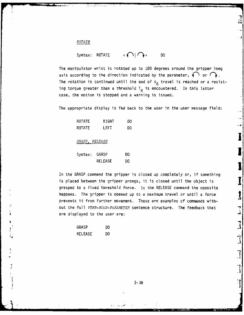
ROTATE
Syntax: ROTATE <{h C> DO
The manipulator wrist is rotated up to 180 degrees around the gripper long
axis according to the direction indicated by the parameter, C)or
The rotation is continued until the end of e 6 travel is reached or a resist-
ing torque greater than a threshold T R is encountered. In this latter
case, the motion is stopped and a warning is issued.
The appropriate display is fed back to the user in the user message field:
ROTATE RIGHT DO
ROTATE LEFT DO
GRASP, RELEASE
Syntax: GRASP DOIRELEASE DO
In the GRASP command the gripper is closed up completely or, if something
is placed between the gripper prongs, it is closed until the object isJ
grasped to a fixed threshold force. In the RELEASE command the opposite
happens. The gripper is opened up to a maximum travel or until a force
prevents it from further movement. These are examples of commands with-
out the full VERB-NOUN-PARAMETER sentence structure. The feedback that W
are displayed to the user are:
GRASP DORELEASE DO
3-3

FORWARD, BACKWARD
Syntax: FORWARD DO
BACKWARD DO
In the FORWARD command, the gripper is moved forward along its axis of
rotation to a distance equal to the length of the gripper's prongs. For
a longer motion, the command is repeated. The command is useful in approach-ing an object for a grasp. According to the configuration of the manipula-
tor, the computer calculates the link motions necessary to cause the gripper
to move forward. In the BACKWARD command, the motion is reversed. The
gripper is moved backward along its axis of rotation to a distance equal to
the length of the gripper prongs. The direct feedback displayed to the user
is the key sequence:
FORWARD DO
BACKWARD DO
MANUAL, CONTINUE
MANUAL is a special primitive command that is not useful by itself (it
causes no manipulator motion) but is very useful within chains. It is
included in the sequence of commands comprising a chain where the opera-
tor's intervention is expected. During chain execution, when this command
is encountered, the automatic, computer-controlled motion is stopped and
control is relinquished to the user. Thus, this command provides a means
to transfer control from machine to man in the middle of an automatic
sequence. The user pushes CONTINUE to give control back to the computerafter he has done his part. The key sequence is:
K4 MANUAL DO during chain definition
CONTINUE after the operator has done his part in
execution
3-37

Notice that CONTINUE is a terminator by itself and can be used in other
cases where command has to be returned to a suspended automatic sequence.
These cases include the expected events (e.g., inserted MANUAL), or
unexpected events (e.g., a simple reflex or force stop).
3.4.4 Chains. Chains are the language structural element that corresponds
to complete subtasks. They are sequences of specific primitive commands
(or other chains) which were defined and labeled by the user as useful
repeated subtasks. They provide the user with the capability to define a
useful sequence only once and later use it repeatedly by calling it asa
unit. The computer then performs that stored sequence automatically, faster
and with less probability of errors. It also provides the capability to
construct tasks by combining a sequence of simpler subtasks in hierarchical
construction. For example, suppose a valve has to be closed and opened
several times ; it might be expedient to define a chain for this task.
Suppose, further, that PATH 4 was defined previously as a path to the jparticular valve and CHAIN 2 was defined to be a chain which approaches
and rotates a valve once. Then the task of closing the valve completely Jcan be performed by the following chain which we call CHAIN 9:
CHAIN 9
GO TO PATH 4
MANUAL
FORWARD
GRASP
GO TO CHAIN 2
GO TO CHAIN 2
RELEASE
BACKWARD
GO TO REVERSE PATH 4
3-38

PATH 4 is traversed forward in the beginning of CHAIN 9 and backward atits end. By using the MANUAL command the computer will momentarily relin-
quish control to the operator after it has brought the gripper into the
vicinity of the valve. This allows the operator to make small adjustments
to bring the gripper exactly in front of the valve. Thus, the adaptive
interpolation is still left for the operator. After FORWARD and GRASP,
CHAIN 2 is called twice to perform the actual rotation of the valve. This
is an example of hierarchically using a chain within a chain. RELEASE
opens the gripper and the last command brings the manipulator back to the
initial position. A PATH is used in this example to bring the manipulator
to and from the valve, making it possible for the manipulator to go around
obstacles with which it might have collided, if GO TO POINT were used.
The commands used to handle chains are similar to those related to paths.
Chains can be defined (and redefined), called for use, and deleted. The
commands causing these actions largely resemble those for the path. In
fact, chains can be considered a symbolic equivalent of paths, where pathscontain stored analog sequences; chains contain a sequence of symbolic
commands which may be primitive paths or even other chains.
DEFINE CHAIN, END CHAIN
Syntax: DEFINE CHAIN <n> DO O<n<9
END CHAIN DO
The DEFINE CHAIN and END CHAIN commands are the de-limiters that indicate
the start and end of the chain being defined. During the definition of
the chain, no manipulator motion takes place--the system is in EDIT state.
In EDIT state, new chains are defined or old ones are updated. When defin-ing a chain consisting of solely symbolic commands, the process of defini-
tion can be made either by going through the chain once and storing the
3-39

sequence or, utilizing its symbolic nature, going out of execution mode
and storing the required sequence without actual execution. The latter
approach was used more frequently because with no manipulator motion the
user can concentrate on the sequence of commands needed and can do it
quicker--as fast as he can key in the commands.
The user enters the EDIT state by starting a chain definition using the
DEFINE CHAIN COMMAND. If the chain already exists it will be redefined;
otherwise, a new chain will be established. The user can then enter the
sequence of the commands making up the chain in the order of their required
execution. The commands entered are displayed for verification in the chain
editing field. As the user enters his commands, one after the other, he can
check the correctness of the entry which is first displayed in the user
input field. If a mistake occurred, he can erase that line by pressing
CANCEL instead of DO. Commands are added to the developing chain when DOis pressed. Current implementation provides no better correction capabili-
ties outside the line correction. If the user wants to replace a command
which he has already entered or to insert a new command in an earlier part
of the chain, he has to redefine the complete chain. The user can then
conclude the chain definition and exit from EDIT state by issuing END CHAIN
command. This causes the CHAIN definition to be closed and the new chain
to be stored under the appropriate label. No check is made by the computer
as to the correctness of the chain. (Better editing facilities should
probably be developed in the future.) IAn additional feature that is provided is the display of a previouslydefined chain for viewing without modification. If the operator wants to Iobserve the content of a chain or to remind himself of its function, he
may issue DEFINE CHAIN, and the chain is displayed. Issuing END CHAIN
brings him back to execution state.
3-40
GO TO CH5AIN n
Syntax: GO TO CHAIN <n> DO O<n<9
Chains are activated by issuing this command. The activation of a chain
is equivalent to a subroutine call where control is delegated to the com-
puter within the duration of the chain's execution. Chain names are numbers
in the range O<n<9, and there is no relation between a chain, a path, or a
point with the same label. When a chain is called, the content of the chain
appears on the screen. The chain primitives are executed one after another
and the chain definition is scrolled on the screen so that the currently
active primitive is shown at the top of the list. Figure 3-6 also presents
an example of the display format during chain execution.
At any point in the chain execution, the user can add correcting commands
to the computer generated motions by manipulating the joysticks to cause
the desired additive motion. For example, if a chain command causes a
motion toward the side of a valve, he can correct the motion while it is
in progress by using the joysticks. Sometimes there is a need to make a
fine alignment manually in the middle of an automatic chain execution.
The user has the option to STOP the motion of the manipulator, perform the
manual subtask, and then press CONTINUE to give control back to the compu-
ter. Automatic execution will commence from the point where the chain
execution was stopped.
There are two commands that may appear in a chain and deserve special
attention. One is the command which calls another chain such as: GO TO
CHAIN 7. This allows chains to call chains to any depth. This is the
mechanism which embodies the hierarchical structure of the chains. The
second special command is MANUAL which, when encountered during execution,temporarily relinquishes control back to the user. Here we have the mixed
initiative feature where the computer temporarily gives control to the user
3-41
-I
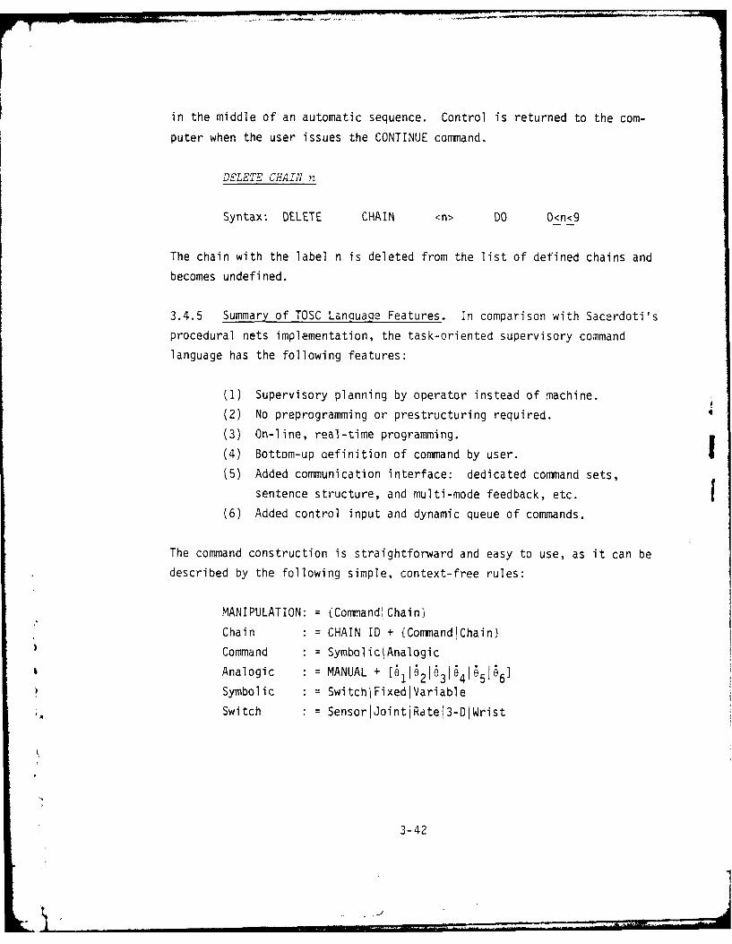
in the middle of an automatic sequence. Control is returned to the com-
puter when the user issues the CONTINUE command.
DELETE CHAIN n
Syntax: DELETE CHAIN <n> DO O<n<9
The chain with the label n is deleted from the list of defined chains and
becomes undefined.
3.4.5 Summary of TOSC LanquaQe Features. In comparison with Sacerdoti's
procedural nets implementation, the task-oriented supervisory command
language has the following features:
(1) Supervisory planning by operator instead of machine.
(2) No preprogramming or prestructuring required.
(3) On-line, real-time programming.
(4) Bottom-up oefinition of command by user. I(5) Added communication interface: dedicated command sets,
sentence structure, and multi-mode feedback, etc.
(6) Added control input and dynamic queue of commands.
The command construction is straightforward and easy to use, as it can be
described by the following simple, context-free rules:
MANIPULATION: ={Command!Chainl
Chain : CHAIN ID + (Command Chain}
Command : = SymboliclAnalogic
Analogic = : MANUAL + [611621o316416515 6]
Symbolic • = SwitchIFixediVariable
Switch = SensorIJointjRatej3-DjWrist
3-42
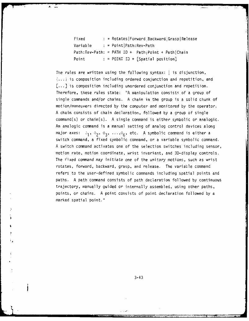
Fixed : : RotatesIForwardIBackwardIGraspIRelease
Variable • = PointlPath:Rev-Path
Path:Rev-Path: = PATH ID + PathlPoint + PathiChain
Point : = POINT ID + [Spatial position]
The rules are written using the following syntax: I is disjunction,
{... I is composition including ordered conjunction and repetition, and
[...] is composition including unordered conjunction and repetition.
Therefore, these rules state: "A manipulation consists of a group of
single commands and/or chains. A chain in the group is a solid chunk of
motion/maneuvers directed by the computer and monitored by the operator.
A chain consists of chain declaration, followed by a group of single
command(s) or chain(s). A single command is either symbolic or analogic.
An analogic command is a manual setting of analog control devices along
major axes: 0I, 02 , 032 ...,a6 , etc. A symbolic command is either a
switch command, a fixed symbolic command, or a variable symbolic command.
A switch command activates one of the selection switches including sensor,
motion rate, motion coordinate, wrist invariant, and 3D-display controls.
The fixed command may initiate one of the unitary motions, such as wrist
rotates, forward, backward, grasp, and release. The variable command
refers to the user-defined symbolic commands including spatial points and
paths. A path command consists of path declaration followed by continuous
trajectory, manually guided or internally assembled, using other paths,
points, or chains. A point consists of point declaration followed by a
marked spatial point."
3-43
i
° . _

4. EXPERIMENTAL STUDY
4.1 Overview
This chapter summarizes the results of a set of experiments performed in
the program years to investigate the efficacy of various communication
factors and the best mode of communication. Specific objectives included
the following:
(1) Examine man-machine communication needs and evaluate the
effects of system factors influencing man-machine communi-
cation.
(2) Investigate the relations between operator performance and
computer aiding along three major dimensions of communica-
tion--control mode, command structure, and feedback display.
(3) Provide data for evaluating overall system effectiveness
contributed by the level of automation provided in a shared
man-computer control paradigm.
Proper evaluation and assessment of a -omplex man-machine system must
include three aspects: (1) capability and quality (e.g., dexterity,
capacity, precision, etc.) that can be achieved, (2) the corresponding
resource consumption and loading for achieving a given performance (e.g.,
power, effort, and attention), and (3) system utilization and efficiency
(e.g., throughput, frequency of use, allocated functions and probability
of success, etc.). Most of the quantitative data obtained in the series
of study are based on the performance time and error. Performance time
data is widely used in the evaluation, due to the ease of measurement ana
its responsiveness to system variation. Under a different control of the
experiment, performance time can reflect system capability (speed),
resource consumption (processing time), or system utilization/efficiency
(time occupancy, and time ratio). For reasons of economics and ability
4-1
7A6-A094 482 PERCEPTRONICS INC WOODLAND HILLS CALIF F/S 5/B
MR801CHIWHCROS A REYN001-6CO6MAN MACHINE COMMUNICATION IN REMOTE MANIPULATION ,TASK-ORIENTED -ETC U)
7JNCLASSIFIE 7TR-1034-8RI NL
2-.EEEEEEEEEEEE
to control key variables, the work discussed below was performed using
the laboratory facility described in detail in Appendix B.
A convenient approach toward the communication mode assessment is based
on performance improvement due to the added functions in the communicationdimensions of interest. The selected functions of interest included the
following: (1) augmented control represented by resolved-motion rate
control (RMRC), (2) traded control represented by automatic motion
control (AMC) using defined points and paths, (3) commnand mix of fixed
and variable primitives, (4) command abstraction level represented by
chain-in-chain structure, (5) display degradation due to environmental
factors, (6) level of details in machine state feedback, and (7) display
format. The evaluation approach was one of observing the incrementalimprovement in performance, which could lead toward the optimal designof man-machine commiunication with well-defined performance indices.
4.2 Evaluation of Man-to-Machine Communication
The principles and guidelines for language design described in the pre-vious chapter were obtained through analytical studies, model construc-
tion, and principles suggested in related fields. A first step to
validate these guidelines and principles is to perform experiments in
the simulated laboratory environment (see Appendix B). The experiments
were conducted following the design, implementation, and modification of
the language features, which, in its final form, was described in Chapter3. The experiments, using 6 to 12 paid subjects, emphasized the effect
of automation (computer-aiding) on three levels: lexial (control andprogramming), syntactic (comm~and mix), and semantic (conmmand organiza-tion) levels:
functions which raised one level of abstraction in
4-2

commiunication. Two dimensions considered are (1) augmented
(serial) control, and (2) traded (parallel) control. Thelevels of the first dimension were (a) individual joint
rate-control, and (b) resolved-motion rate-control. The
levels of the second dimension were (a) direct control, and
(b) automatic motion control, where the operator could call
on a predefined point in symbolic, push-button control.
(2) Commnand Mix. Is the effect of the lowest level of commnand
structuring, i.e., the sequencing and grouping of the
conmmands including point, path, and fixed primitives in
sentence structure. This represented a mixing of symbolic/
analog commnands and serial and parallel computer aiding.
The levels of this dimension were (a) basic commands, where
the operator could call on symbolic primitives in manual
sequence, (b) variable commnands, in which the language
provided a facility to define in real time variable commnands
as groups of mixed symbolic or analogic primitives.
(3) Commnand Organization. Is the effect of the higher level of
commiand structure, i.e., the chain-in-the-chain function of
the commnand and appropriate manual check-point fur higherlevel task oriented commnands. The levels of this dimensionwere (a) fixed commnands, same as the basic commands above,(b chained commnands, in which the language provided afacility to define multiple levels of chains of a lower level
of commands.
Two versions of control/display station were used in the studies: direct
viewing and indirect viewing. Figure 4-1 shows a drawing of the more
complete, newer version of th~e control/display station which consists of the
4-3

FIGURE 4-1. II
TELEOPERATOR CONTROL/D ISPLAY STATION
4-4I

dedicated command keyboard and two three degree-of-freedom, rate control,
self-centering joysticks. A 9" CRT display was used to provide alpha-
numeric messages concerning the condition of the system, the keyboard
&i inputs, and the next command in the execution queue. A 2-view black-and-
white TV viewing system added in later experiments was placed in front
of the control panel to represent an indirect viewing situation.
The experimental studies reported in the following sections were divided
into training and test phases. In the training phase the participants
practiced basic manipulation and some constituent elements of the experi-
mental tasks under specified conditions. In the test phase, the partici-
pants were required to apply the skills they developed during training
to perform a simulated maintenance task using the pipe structures (Figure
4-2). The simulated task incorporated a representative sample of task
elements that are frequently performed in underwater manipulation (e.g.,
orient and position the end-effector, gross travel, vertical and horizontal
alignment, grasp and release objects, etc.), into a single integrated
task with a defined goal. The participants were allowed to plan their
strategy formally or informally before each experimental session.
Performance measures consisted of task performance time and error committed
by participants in performing assigned tasks. When traded control was
used, both task definition time and execution time were recorded to pro-
vide an estimate of the overall task conpletion time.* Since the overall
maintenance task can be easily divided into subtask elements, the perfor-
mance of the major subtask element, the valve turning task, was also
evaluated and serves as a comparison in the following sections.
The initial intent of this evaluation was to provide an operational
context for testing the features of the communication language developed
analytically. As such, the experimental study was more a tool for the
development of the language design guidelines than a rigorous demonstration
Oefinition time is the time spent in constructing user-defined variablecommands (i.e.. wen the. operator is giving instructlo solely to thecmputer). Execution tim includes the tim in actliating commends,(I.e., passing Instruction to manipulator through computer) and the timein monitoring and controlling of mnipulator motion. Overall completiontime is simply the interval from the tine the task goal is. given to thetim the goal is reached.
4-5
L

..- ... . .r......
sm'v .. t
4-6-

of absolute system effectiveness. It would be difficult to compare the
results in absolute terms with other experiments conducted on different
manipulators, different tasks, and differently trained operators.
4.2.1 Control and Programming. The initial year's study (Berson, et al.,
1977) evaluated separate effects of two basic aiding techniques: the
resolved motion rate control (or spatial control) and the automaticmotion control (i.e., go-to-point using gross control buttons). Subjects
were required to perform a simulated maintenance task based on an initial
setup of pipe structure. It contained two gate valves and arms, four
sear rings, and a storage box for seals. The 2x design for control and
programuing evaluation included the following conditions:
(1) Direct control - unaided joint control.
(2) RMC - Control of manipulator wrist motion along X-Y-Z.
Coordinate axis was provided by the right joystick.
(3) Direct plus automatic motion control (AMC), where the
computer automatically moves the manipulator to preassigned
locations.
(4) RMC plus AMC.
Figure 4-3 presents the task execution time under each of the four controlmodes. The overall comparison between direct control and RMC indicatedthat the participants performed significantly better under RI4C than theydid under direct control (P < 0.025). No significant main effect wasobtained for AM4C and the two-way interaction was not statistically signifi-cant. Analysis of the valve turning data indicated that while task
execution times were less with AMC than without it, the difference was not
statistically significant. The analysis indicated that the need to defineextra spatial points for proper operation and the inefficiency in activat-
ing go-to-point function buttons reduced the advantage gained in the use
.4
4-7

1600 800
0 MANUAL
GO-TO POINT/PATH
, -
S1400 700
e-
> 1200 --600
1000 5 0
t(IDIRECT ,. RCI DIRECT RMRCLOVERLL TASK VALVE TURNING SUBTASK
lFIGURE 4-3.
AVERAGE TASK EXECUTION TIME AS A FUNCTION OFBASIC CONTROL AND PROGRAMMING MODES
4-8
L.

of AMC. The study concluded that augmented control, in the form of
resolved motion of the wrist joint, almost universally reduces task per-
formance times and error rates as compared with unaided manual control.
This performance improvement is particularly high for tasks requiring
fine, dexterous control and simultaneous multi-joint control. The automatic
motion control could be useful for tasks with many repetitions or for
tasks with few repetitions but with low definition and activation time.
4.2.2 Commland Mix. The second year study (Crooks, et al., 1978) evalu-ated the potential benefits of mixed analogic and symbolic commuands which
could be fixed symbolic or user-defined. Concerning the structure ofvarious means by which the operator transmits instructions to the remote
manipulator, previous experience suggests the following commnand structure:
(1) When a variety of tasks are to be performed, a multi-mode
supervisory control is needed for the operator to select
from a variety of computer-aided control modes.
(2) Commnand structures should allow both analogic and symbolic
primitives in serial or in parallel, and allow smooth trans-
ition among control modes.
F(3) Selection of any control function should be as simple aspossible, involving:
(a) A single commnand to request a control function.
(b) One command that initiates one unitary element.
(c) An interface that minimizes the time and effort to
select the commnand.(d) Automatic selection of control mode where feasible.
4-9

(4) When control functions must be performed in sequence, auto-
matic functions should provide appropriate interpolation in
actions or the interface should prompt the operator with the
next required step.
The experimental study has selected to investigate the main effects of
command mix in two levels: (1) Basic mode, which allowed the use in
sequence of both analogic and low-level, unitary motion, symbolicprimitives, and (2) Variable mode, which allowed in the commnand sequence
the user-defined variable commands, including Point, Path, and Chain. A3x2x2 repeated measures design was used to examine three task conditions,
with two levels of command structure, over two trials. The three task
conditions were Baseline, Increased Variability (with more non-repeatable
subtasks) and Increased Complexity (with more repeatable subtasks). The
experimental procedure allowed variable commnands defined in Trial 1 to
be used in Trial 2.
Figure 4-4 presents the task performance time as a function of commandstructure and task condition. The effects of task and trial number weresignificant (P < 0.01). This is mostly due to the definition time overhead
in the first trial and the performance gain achieved in the second trial within
variable command mode. There were slight improvements in overall taskj
execution time using variable commands; the effect was not significant.This is reflected as the slopes of solid lines in Figure 4-4. Actually,
the upward slopes of the dotted lines represent the definition time over-head, while the downward slopes of the solid lines represent the perfor-
mance gain in execution time. The comparison between task and valve-
* turning subtask shows that the performance of the valve-turning subtask
closely parallels the overall task performance except that the valve- -
turning subtask has very low definition overhead in general, and has high -
4 performance gain in high-complexity tasks, which has increased repeatable
4-10

BASIC - ALLOWING FIXED, SYMBOLIC2000 COMMAND ONLY 1000200 VARIABLE - ALLOWING USER-DEFINEDI
VARIABLE COMMAND 13 HIGH-COMPLEXITY TASK
V HIGH-VARIABILITY TASK
0 BASELINE TASK
---- FIRST TRIAL (COMPLETIONTIME)
cr SECOND TRIAL (EXECUTIONTIME)
1600 - 800
0.1.
1200 --. - 600
-0a
800 400
£ I I I I
it IBASIC VARIABLE BASIC VARIABLE
OVERALL TASK VALVE TURNING SUBTASK
FIGURE 4-4.AVERAGE TASK PERFORMANCE TIME AS A FUNCTION OFCOMMAND STRUCTURE AND TASK STRUCTURE
4-11
01,

task elements. This was thought to be due to the discrete and repetitive
nature of the valve-turning subtask which, when using appropriate variable
commands, can be easily defined by a group of symbolic commands and
executed automatically without operator intervention. The results demon-
strate the potential benefits to be gained by using variable commnands in
tasks which must be repeated one or more times. Better improvement can
be expected in procedural repetitions than in trajectory repetitions, asthe latter ones usually require higher definition time and demand mare
operator intervention than the former ones.
4.2.3 Commnand Organization. The third year study (Crooks, et al., 1979)evaluated the effect of higher level command organization, mainly the
use of and the confidence associated with multiple-level chain-structure.Previous experience suggests the following command organization in a multi-mode supervisory control paradigm:
(1) The communication should take place at the highest symboliclevel comfortable to the user. Giving commands in too much
detail would cause the user to lose sight of the overall task
while dealing with the details. One the other hand, giving a
command at a gross level does not allow adaptation of the
command to the peculiarities of the situation at hand.
(2) High level commnand construction should be achieved using
hierarchical organization of user-defined variable commands.
This structure could expedite modularity, parallel process--
ing, and error isolation in both task definition and
execution. A manual facility should be incorporated in the
system that can be used easily in any level of hierarchy.
(3) By providing a manual request, computer prompting, real-timetrajectory editing, and hierarchical feedback of machine
4-12

state, a mixed-initiative control allocation between operator
and computer can be achieved.
(4) Composite constructs (chains in symbolic and paths in
analogic) should be easy to use, involving:
(a) A definition capability.
(M A labeling capability.
(c) A display for review capability.
(d) An editing capability.
(e) An activating procedure.
(f) A progress display capability.
The experimental study, conducted in an indirect viewing situation evalu-
ated performance at two levels of command organization: (1) Fixed command,
where no user variable command was used, and (2) Chained command, where
commtand organization up to two-to-three levels of chaining was allowed.
A Wx repeated measures design was used to examine the effects of comm~and
mode under two levels of visibility. The visibility effect was established
using the contrast and brightness controls to maintain 59% and 17% contrast
ratios for normal and degraded viewing conditions.
The average task performance time data are presented in Figure 4-5. The
results of a within-subject analysis of variance on task ex-.ecution timeindicated that participants performed significantly better (faster andmore consistently) using Chained commands than they did using Fixed com-
mands (F = 52.66, P < 0.001). This represents a 51% reduction in execution
time with the normal visibility and a 60% reduction with the degradedb visibility (t = 2.97, P < 0.05). The visibility effect was found signifi-
cant in the Fixed command mode in which the participant took an average ofki 17% longer time to complete the task with the degraded TV than with the
4-13

FIXED - ALLOWING LOW-LEVEL, FIXED
1200 COMANDS ONLY * 600CHAINED - ALLOWING VARIABLE COMMANDS,
ORGANIZED IN 2-3 LEVELS OF o NORMAL TVCHAINS COMPLETION TIME
-EXECUTION TIME
(EXECUTION + DEFINITION)
300 , Do
c oo 200 ]
FIXED CHAINED FIXED CHAINED
-'-I I I -
OVERALL TASK VALUE TURNING $U8TASK
AS A FUNCTION OF COMMAND LEVEL
4-14
U.a

clear TV (t = 2.61, P < 0.025). The effect was much reduced in the Chained
command mode, to the degree that the use of Chained commands had effect-
ively maintained normal level of performance within the visibility ranges
tested. In other words, the Chained command is potentially more effective
in degraded than in normal visibility. In fact, a significant 18% reduc-
tion in task completion time (t = 2.76, P < 0.025) was obtained with the
Chained command, the first evidence ever obtained for significant reduction
of overall completion time with various traded control modes.
Separate task performance analyses were conducted for three major subtasks
to provide a comprehensive description of the contribution of each sub-
task to total task performance. A compa'-ison based on subtask character-istics, command utilization, and resulting performance was made. It showed
that the valve turning subtask was the one receiving higher pay-off in
the use of Chained commands, judged by its high task time reduction (49%),
its high time benefit/overhead ratio (between 3.75 and 3.45 for the con-
ditions tested), and its significant error reduction. This was due to a
proper match of symbolic commands with a task of repetitive and structurednature, which may be further characterized by trajectory discreteness and
simplicity, precision requirements, and environment uncertainty.
4.2.4 Sunmary of Man-to-Machine Communication. A comparison was made oftime performance improvement for vanious command/control modes based onexecution time or completion time ratios. As shown in Table 4-1, perfor-
* mance ratios vary significantly among control/command modes, task types
and environmental conditions. The first observation is that the high-
level chain commands, along with a complete set of language features, had
the highest improvement in task execution, especially in degraded viewing
situations. The degree of improvement varies among the type of tasks.
The maintenance task is the most complex task, with the highest numnber ofsteps, with few (1 to 2) repetitions on spatial point/trajectory, and
4-15

TABLE 4-1.
PERFORMANCE TIME RATIOS FOR VALVE TURNING,RING PLACEMENT, AND MAINTENANCE TASKS
**
TEST TIME RATIOS RING/CAPCONTROL MODES PHASE MAINTENANCE TASK VALVE TURNING PLACEMENT
RMC/DIRECT 1 0.91 + 0.99 0.78 +
(AMC+RMC)/RMC 1 0.98 0.93 (1.10)
VARIABLE/FIXED 2 0.95 0.88 0.56+
2 (1.08) (0.95) (1.20)
CHAINED/FIXED 3 0.44++ 0.33+ 0.53++
(NORMAL VIEWING) 3 (1.02) (0.57) (1.16)
CHAINED/FIXED 3 0.40++ 0.30 ++ 0.43 ++
(DEGRADED VIEWING) (0.84) (0.51)' (0.90)
DIRECT - MANUAL RATE CONTROL
RMC - RESOLVED MOTION RATE CONTROLAMC - RECORDED POINT/PATH MOTIONSFIXED - BASIC PRIMITIVES PLUS RMCVARIABLE - POINT/PATH PLUS FIXEDCHAINED - CHAIN-IN-CHAIN PLUS VARIABLE(Note that although no formal comparison between Fixed Mode and RMC modewas made, it was observed that only small (up to 10%) performance timeadvantage was obtained for Fixed Mode over RMC Mode)
BASED ON EXECUTION TIME (WITHOUT PARENTHESIS) OR COMPLETION TIME (WITHPARENTHESIS). Ratio of 1.0 = Equivalent performance for the testedconditions. For the definition of execution time and completion time,see Footnote on page 4-5.
+ 0.05
p < 0.005
4-16

with highest level of procedural structure. The valve turning task is the
most discrete task with several low-level motion repetitions, and with the
highest percentage of symbolic commnand usage. The ring/cap placement
task required multi-joint trajectory and few (2-3) repetitions of traject-ory. From system effectiveness point-of-view, Rt4C was the most effectivein ring placement task where coordinated multi-joint control was required.
The single Go-to-Point command was not particularly effective until it
was incorporated in a structure used with Go-to-Path and other symbolic
commands which existed in the variable command mode. With these, great
time reduction (of 44%) in the execution of ring placement tasks was achieved,
as the task required full trajectory repetition. However, the definitiontime overhead was so high that the total completion time was 20% higherthan the fixed command.
Several factors were at work in performance improvement with the use of
Chain command, compared to Fixed command. They are: high-level structureof task procedure, motion and procedure repetitions, use of Point andPath, and Point/Path repetitions. As shown, the overhead of Point/Pathprocedure definition was high in the maintenance task and ring placementtask, and low in the valve turning task. Thus, the resulting execution
and completion times were significantly lower in this command mode forthe valve turning task, while the use of Chain command was marginally
a effective for the ring placement task.
To further clear up the working factor in Chained command modes, Table4-2 summarizes performance time ratios for four levels of preprogrammningover task procedure or task trajectory. As expected, the biggest gainscan be achieved with both procedure and trajectory can be reliably pre-programmed (4-2D) followed with preprogrammed trajectory alone (4-2C).Significant gains can also be achieved with preprogrammed procedure alone
in degraded visibility or with highly structured task (4-2B). The true
4-17

TABLE 4-2
PERFORMANCE TIME RATIOS:CHAINED COMMANDS VS. FIXED COMMANDS
(A) NO PREPROGRAM (B) PREPROGRAMMED CHAINSSTRUCTURED-
VISIBILITYJLOW MEDIUM HIGH LOW MEDIUM HIGH
CLEAR 1.16 1.02 .57** CLEAR .98 .85 .46*"
DEGRADED .90 .84* .51** DEGRADED .76* .71** 41"
(C) PREPROGRAMMED POINT/PATHS 'D) PREPROGRAMIMED POINT/PATH/CHAINS
S S
LOW MEDIUM HIGH LOW MEDIUM H'IGH
CLEAR .71 .61* .45* CLEAR .53** .44 .33**
DEGRADED .57* .53"1 .40* DEGRADED .43*" .40** .30
* P.'O.O5i ""P-:0.05
4
'I
I 4-18-

achievement of Chain commnand over Fix commnand was with highly-structuredtasks or tasks under degraded visibility (4-2A).
4.3 Evaluation of Machine-to-Man Commnunication
Two issues were of major concern in evaluating commnunication from machine-
to-man: machine state and workspace feedback requirements. The symbolic
conmmand language alters the cognitive and task requirements of the mani-
pulator operator. Most of the new requirements, as described in Chapter
2, involve conmmunicating with the computer. Especially in multi-mode
supervisory control, the operator not only provides direct analog control
of the manipulator's movements, but also (1) selects and confirms available
computer-assisted functions, (2) determines what control mode is currently
operating, and (3) monitors the progress of automated routines, etc. The
purpose of the first experiment was to determine the effect and the amount
of machine-state feedback required when using the multi-mode control and
hi gh-level comm~ands.
Another consideration is the effect of environmental factors in underwater
manipulation, such as sediment, turbid water, failure of external light-
ing, or poor angle of view, which often results in poor visibility. In
these cases, laboratory studies and practical experience have shown thatperformance is severely degraded--frequently to the point where it is
impossible to proceed (Pesch et al, 1971; Estabrook, 1975). One suggestedmeans to compensate for poor visibility, as demonstrated in previous
sections and other researchers (e.g., Sheridan et al, 1979), is to auto-
mate some manipulator motions or procedures. Such preprogrammned computer
controls can proceed "orderly" once they are initiated. One important
question is how different are the display requirements for various taskautomation levels.
4-19
all

r17The intent of the evaluation studies to be discussed in the following
sections was to provide an operational context for examining the feedbackdisplay requirements in the use of various commnand features. Similar to
the studies discussed previously in Section 4.2, the objective of these
studies was one toward performance improvement, rather than one toward
optimal selection of commnunication modes. The question, then, is how to
define and to establish the improved feedback with a given commnand mode.
The variables of interest were chosen to represent the candidates for
system modification, which might present potential performance bottlenecks.
The performance bottlenecks refer to the situations when the performance
measures of interest are expected to respond or improve substantially
only when some of the modifiable parameters are varied within a certainregion. As such, the studies discussed in this section were a diagnostic
and relative evaluation in nature, and represented the required observationof possible machine-to-man commu~unication bottlenecks in the current languagedesign.I
Six to eight subjects, trained in using various control modes, were used
in the experiments. To provide the capability for multi-mode visualfeedback, the operator's display/control console was equipped with a 3D-stick-figure graphics, a 2-view black and white TV viewing system, andIa 9" state-feedback monitor (see Figure-4-6). The variables of interest
included the following:J
(1) Machine state feedback level.
(a) Gross state--display of current commnand only.
4 (b) Detailed state--display of queue list of coummands andcurrent commnand.I
4 -20
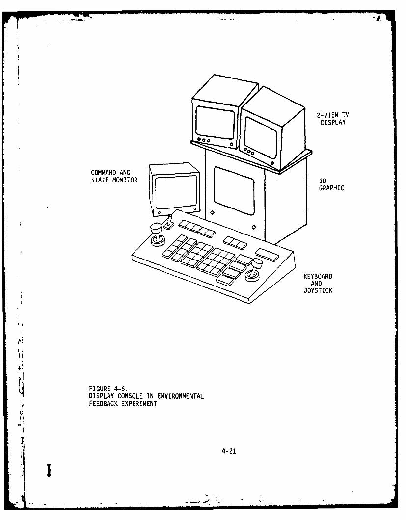
2-VIEW TV
~ DISPLAY
GRAPHIC
KEYBOARD
JOYSTICK
FIGURE 4-6.DISPLAY CONSOLE IN ENVIRONMENTALFEEDBACK EXPERIMENT
4-21
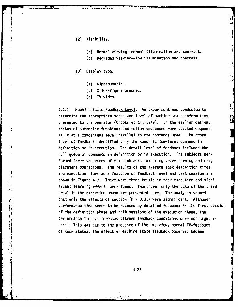
(2) Visibility. L(a) Normal viewing--normal illumination and contrast. -'
(b Degraded viewing--low illumination and contrast.
(3) Display type.
(a) Alphanumeric.
(b) Stick-figure graphic.
(c) TV video.
4.3.1 Machine State Feedback Level. An experiment was conducted to
determine the appropriate scope and level of machine-state information
presented to the operator (Crooks et al, 1979). In the earlier design,
status of automatic functions and motion sequences were updated sequent-
ially at a conceptual level parallel to the commiands used. The gross
level of feedback identified only the specific low-level conmmand in
definition or in execution. The detail level of feedback included the
full queue of commnands in definition or in execution. The subjects per-formed three sequences of five subtasks involving valve turning and ringplacement operations. The results of the average task definition times
4 and execution times as a function of feedback level and test session are
shown in Figure 4-7. There were three trials in task execution and signi-
ficant learning effects were found. Therefore, only the data of the thirdtrial in the execution phase are presented here. The analysis showed
that only the effects of section (P < 0.01) were significant. Although
* performance time seems to be reduced by detailed feedback in the first session
of the definition phase and both sessions of the execution phase, the
performance time differences between feedback conditions were not signifi-
cant. This was due to the presence of the two-view, normal TV-feedback
of task status, the effect of machine state feedback observed became
4-22

80
60 -SESSION I
I-I
S 40
SESSIOI 2
20
GROSS STATE DETAIL STATE GROSS STATE DETAIL STATEFEEDBACK FEEDBACK, FEEDBACK FEEDBACK,
DEFINITION/CONTROL PHASE EXECUTION PHASE
STATE FEEDBACK LEVEL
FIGURE 4-7.AVERAGE TASK PERFORMANCE TIME AS AFUNCTION OF STATE FEEDBACK LEVEL
4V
4-23
'I". ~ .
secondary. Besides, subject's opinion indicated the difficulty in keeping
up with the speed of updating low-level command sequence with the use of
detailed state feedback. A later design using the display window and moving
arrow received much better acceptance from the subject.
4.3.2 Machine State and Environmental Feedback Formats. Visual observa-
tion of a remote manipulator task has been a critical factor in machine-
to-man commnunication in almost all previous experimental work. As we
move toward automated manipulation, it is logical to ask whether the
typical natural pictorial displty (direct or TV viewing) can be replaced
by a more abstract display of events at the manipulator workplace without
degrading system performance. Three perspectives were considered:
(1) Availability and advances in graphic display technology
provide an excellent potential for efficient man-computer
commnunication. The degree of success of this approach (i.e.,
to what extent a typical natural pictorial display can bereplaced by an abstract display of events at the manipulator
workspace without seriously degrading system performance)should be tested against available technology.
(2) A typical computer-generated display would require high
sensing and processing capabilities and large bandwidth to
duplicate even a simple natural scene. With system limita-
tions and cost under consideration, it is essential to evalu-
ate the sufficiency of reduced-cue presentation.
(3) Display requirements may be different for various task auto-mation levels. Proper methods for display synthesis remain
to be developed comm~ensurate with task requirements andoperator capabilities. As a first step, ob~prvation can be
4-24

made in comparing the effect of display fornat on operator
performance under different task situations.
This section describes an experiment conducted in the current year in
comparing different types of visual display for automated, remote manipu-
lation. The apparatus used, the procedures followed, and the data recorded
are reported in the subsequent paragraphs.
Three-Dimensional Graphic System. A graphic representation of stick figure
images of the manipulator and static task objects was given in a 3-D graphic
terminal. The system accepted a series of processed position sensor
information and provides a series of 2-D pictures in their true spatial
relationship. The 3-D image was created by a mirror mechanism positioned
in front of a fast CRT. The mirrors vibrated back and forth to produce
a volumetric change in the viewed image. In the computer, the image was
made up of a stack of X-Y (horizontal-vertical) planes. Each plane
represented the information at a given depth in the Z (depth) direction.
Z planes were stored in digital memory and oiitputed sequentially, in
synchrony with the movement of the mirror unit. The net effect was a
real 3-D image, in that each plane was inherently transparent. By chang-
ing the viewer's position with respect to the display, one could observea parallax containing image.
For the convenience of the experimental study, the image map of objects
and environment was prestored as static background. Manipulator position
feedback signals were the only raw data that were processed to represent
the workspace interaction. Manual calibration of the relative position* between selected manipulator path and selected environmental objects was
required before each experimental session to ensure accuracy in spatial
correspondence. During manipulator operation, the feedback position was
given by the six angles of the joints. Those analog signals were digitized
4-25

by the modular interface and monitored by the computer. The XYZ coord-
inates of the end point were then computed and displayed with the lengths
of the manipulator links given. In this hypothetical mode of operation,
images of work space were created bearing the detail of about 1" in the
operating space. This limitation was attributable to the size of the
display volume, the resolution of the imagery system, and the resolution
of the feedback signals. The analog position signals were limited to a
resolution of about 0.5". Although the display space could be considered
to be a 256x256x256 raster, the real-time processing and memory constraints
limited the image complexity to a maximum of about 4000 points. The
actual image space was about 5 inches by 4 inches by 2 inches. Real world
objects appeared quite small in the display space. The static background
consisted of the basic elements of the task object, work table, represent-
ative obstacles and receptacles. The display is shown in Figure 4-8.
Environmental and State Feedback Display. As a baseline study for indirect
viewing of the work environment, a single-view, black and white TV viewing
system was used. Two 12" (diagonal ) video monitors were placed above the
3-0 display and in front of the control panel. Only the one with frontview was used in the experiment. No camera control (pan, tilt, or form)
was provided, which prevented any changes in the camera view. One dimen-sion of this experimental study was visibility simulation which repre--
sents combined attributes of TV monitors, camera and environmental factors.
A simplified, two-visibility level, similar to those used last ypar (Crooks
et al, 1979) was established through contrast and brightness control of
the monitor. The normal viewing condition corresponded to a contrastratio of 59% and the degraded one corresponded to a contrast ratio of 17%.
A 9" video monitor was placed beside the control panel and below the 3-Ddisplay. It was used to display alphanumeric feedback concerning conmmuni- -
cation with the automatic conmmand program. The modified machine feedbackdisplay was used in the experiment. As shown in Figure 4-9, the list of
4-26

3 1
10 I 14 _
7 8 9 1 13
b FIGURE 4-8.STICK-FIGURE 3-D GRAPHIC DISPLAY OF MANIPULATORAND WORKSPACE (VIEWED FROM RIGHT). LINES 1 THROUGH 3
* REPRESENT MANIPULATOR CONFIGURATION; LINES 7 THROUGH 15REPRESENT THE STATIC BACKGROUND
4-27

CONTROL: JOINTRATE: 3SENSOR: ONINVAR:3-D: ONDEF-PTH:
DISPLAY/DEFINE CHAIN 0
FORWARD DOGRASP DOROTATE COUNTER-CLOCKWISE DO
RELEASE DO
CHAIN 3 CONTROL: JOINTRATE: 3
SENSOR: ONGO TO PATH 1 DO SNSR: O
MANUAL DO 3-0: ON-,-GOTO CHAIN 0 DO DEF-PTH: IMiANUAL DO DFPH
GO TO PATH 0 DOFORWARD DOGRASP DOROTATE COUNTERCLOCKWISE DORELEASE DOBACKWARD DO
GO TO CHAIN 3 DO
FIGURE 4-9.MODIFIED MACHINE STATE FEEDBACK DISPLAY DURINGCHAIN DEFINITION (TOP) AND DURING CHAIN EXE-CUTION (BOTTOM)
424! 4-28
I!--

higher commiands is posted in the left portion of the screen with slow
update rate, while the list of lower level commnands is displayed in the
central portion of the screen with fast update rate. This two-level
presentation appeared to provide easier perception of machine state than
the previous design.
Experimental Variables. Two hypothetical tasks were used in the experi-
ment. The first one was control-oriented and was used to evaluate the
feedback format of environmental interaction. The setond one was super-
vision-oriented and was used to evaluate the feedback format of machine
state (in terms of task progress). This classification of feedback
requirement was solely for the convenience of evaluation, and the physicalpresentation of the two types of feedback were not mutually exclusive.The levels of each dimension of interest were as follows:
(1) Environmental Feedback.
(a) Normal TV viewing - normal illumination and contrast.
(b) Degraded TV viewing - low illumination and contrast.
(c) 3-D graphical display - high illumination and contrast
with low resolution.
(2) Machine State Feedback.
(a) Normal TV viewing.
(b) 3-0 graphical display.
(c) Alphanumeric display of commiands.
b(3) Control Mode.
(a) Direct control -direct manual control of each manipu-lator joint.
4-29

T
(b) Resolved motion control - spatial X, Y, Z axis motion
of the end-effector may be specified through joystick.
Performance measures consisted of task completion times and errors
committed in performing assigned tasks. The time expended in the con-
stituent elements :f task operation, along with the errors including
improper contact, dropping the object, and inappropriate command entry,
was recorded. In all the experimental conditions, participants were
instructed to perform the task as speedily as possible, allowing minor
errors for each task performance.
Tasks and Procedures. Prior to the experimental sessions, four partici-
pants underwent several hours of orientation and practice. This
unstructured practice included:
(1) Manual manipulation.
(2) Automatic command and control.
(3) Single-view TV in degraded condition.
(4) Brief viewing of 3-D display.
Two tasks were used in the experiment: the manual X-Z plane (horizontal- Idepth) positioning task, and the automatic monitoring of a simulated main-
tenance task. The manual positioning task performance evaluation followed
the standard peg-in-hole task description. Namely, the task was divided
into two phases: "reach" and "position." The "reach" phase was from
start to within 3" of the receptacle. "Reach" time was assumed to be
linearly related to distance and independent of final tolerance. "Pos-
ition" time was assumed to be independent of distance and best modeled
as a logarithmic function of tolerance. According to Fitts' index of
difficulty in positioning task, Id = ln (2A/(B-C)}, where A is range
distance and B-C is tolerance. Various amounts of tolerance were used to
43
i ' 4-30'1j

evaluate the level of task difficulty that can be supported by the limited
resolution of the 3-D display. For 80% successful completion of the task,
a tolerance of more than 1.5" was required with the use of current 3-D
display.
The automatic monitoring task was a modified version of last year's simu-
lated maintenance task (Crooks, et al, 1979). The task consisted of the
following subtasks:
(1) Go to the top valve.
(2) Rotate the top valve clockwise.
(3) Go to the cap in the crossbar.
(4) Grasp the cap and remove it.(5) Place the cap on the table.
(6) Pick up the cap from the table.
(7) Transport the cap to a position over the crossbar.
(8) Place the cap in the crossbar.
(9) Go to the top valve.
(10) Rotate the top valve counterclockwise.
(11) Return to the stow position.
To accomplish the automatic monitoring task, the participants were instruct-
ed to accurately define a two-level chain command with a sequence of
manual checkpoints embedded. Then, to perform the task, the participants
could simply activate the chain execution, monitor the subtask completion,and maintain continuous execution by depressing the "continue" key at the
appropriate time. The chains utilize four points and two paths. The
location of the points was as follows:
(1) Over the table, at a height corresponding to that of the cap.(2) Between the table and top valve, of sufficient height over
M the latter to prevent collision with it when traveling to
point 3.
4-31

(3) Over the top valve at a distance corresponding to that
traversed by execution of a "backward do" command from the
valve-grasp position, so that future execution of a "forwarddo" command will position the gripper to grasp the valvethrough execution of the "grasp do" command.
(4) Over the cap in the crossbar, at a distance corresponding
to that traversed by execution of a "backward do" commandfrom the cap grasp position, for reasons same as above.
The location of the paths was as follows:
(1) Traversing points 1-2-3, in order to provide arm movementfrom the table to the top valve.
(2) Traversing points 3-2-4, in order to provide arm movement
from the top valve to the cap.
Once the task commenced, the participants were asked to perform the sequence
as quickly as possible. The major efforts required of the participants
were to recognize, and respond to the embedded manual checkpoints utilizing
three separate types of feedback: alphanumeric messages, 3-D pictorial,
and normal TV viewing.
Results. The average task compleiton time for the gross positioning
task as functions of feedback type, control mode and trial number, aregraphed in Figure 4-10. The results of a within-subject analysis of
variance indicated that only the effect of control mode was significant(F = 19.4, P < 0.01). No significant main effect of display type was
obtained and the two-way interaction (control x display) was not statist-ically significant. Comparing the display type, we found that par-
ticipants were able to use the 3-0 stick-figure display in performing the -
task within a reasonable error rate (<20%) and that they were faster
using the 3-0 display than using the degraded single-view TV display,
4-32

30
IST TRIAL
2ND TRIAL
w 20 1ST TRIAL
2ND TRIALz
0
SPATIAL CONTROL
00
0 I I I
NORMAL TV 3D GRAPHIC DEGRADED TV
ENVIRONMENTAL FEEDBACK
* FIGURE 4-10.AVERAGE TASK COMPLETION TIME AS A FUNCTION OF CONTROL MODE ANDFEEDBACK TYPE FOR A GROSS POSITIONING TASK.
4-331
;4 . .....- .... .., . , _ _.

M W 1- N 9 1
although they incurred a higher error rate in the former case than in the
latter case. This observation suggested that while depth perception wasimportant in this X-Z plane positioning task and the limited, but direct,depth perception provided by the 3-D stick-figure display was helpful,the major limitations in such a display remains to be its low resolution.
Some other handicaps noted included inexact correspondance between image
workspace and physical workspace and difficulty in recognizing details
in physically small features. All these have limited the use of such a
display to tasks with simple (one degree-of-freedom) and gross (high
allowance and low interaction) motion, such as object transfer and gross
alignment tasks demonstrated in the experiment. In these cases, the
stick-figure display has the potential to achieve a better performance
than can be achieved by a degraded TV-display.
The average task execution times in monitoring the simplified maintenance
task as a function of display type and trial are graphed in Figure 4-11.
The effect of display x trial interaction was significant (F = 11.57,
P < 0.05). As shown in the figure, time performance of the TV displaywas superior to that of the graphic display in the first trial. The
reverse was true, however, in the second trial. Since similar resultsjwere also obtained with the alphanumeric display with which the partici-
pants were well-aquainted, the interaction effects cannot be attributed
solely to direct learning (in the use of rather abstract stick-figure
display). Instead, user confidence (in the automated procedure) and the
presentation of cue to motion completion were thought to be the major
factors. The three types of display, TV, graphic, and alphanumeric -
provided the full-cue, reduced-cue for motion, and explicit message
situations. Observations in the experiment suggested that the concept
of a subjective confidence level may be used to describe the participant'smonitoring processes as a continued observation of relevance cue until
the confidence level was reached and action initiated. Overall, these 7
4-3

110
IST TRIAL100
.- 90
2ND TRIAL
o 80
II
~- 70Li
Lii
60
50
SINGLE TV 3D GRAPHIC ALPHANUMERIC
STATUS FEEDBACK DISPLAY
FIGURE 4-11.AVERAGE TASK EXECUTION TIME FOR THE MONITORING OF A SIMPLIFIED
N: MAINTENANCE TASK USING THREE SEPARATE DISPLAYS OF STATUS FEEDBACK
ot
L. 4-35
I..

findings suggest that in monitoring the preplanned process, performance
time can be reduced by using a reduced-cue presentation which, in effect,
has lower noise and interference, provided that both cue sufficiency and
user confidence have been obtained.
Comparisons were made of the effects of display format on operator perfor-
mance with two very different types of tasks: The manual positioning
task and the procedure monitoring task. The first one resembled trackingcontrol and required close interaction between control and feedback. Itrequired multiple cues in depth and motion perception. Considerable
impairments in performance speed and accuracy could result from low
resolution, insufficient cues or degraded environment. The second taskresembled the detection/recognition task, except that it was simplified and
could be accomplished by using motion cue alone. In such a case, perfor-mance was less affected by resolution and display factors.
4.3.3 Summary of Machine-to-Man Communication. Studies were made evalu-
ating the effects of the feedback format and level (detail and visibility).
In summary, comparisons were made of time performance ratios for various
feedback conditions. The results, shown in Table 4-3, were grouped into
two categories: the control/definition phase, where the participant's
were mostly in the control loop, and the monitoring/execution phase,
where the participants were mostly in the supervision loop, with occasional
control activities. In general, performance was more sensitive to feed-
back conditions in the control phase than in the monitoring phase, and
more sensitive to feedback level than to feedback format within the ranges
of variation made during the studies. The values obtained were essentially
averages across control and command modes and thus they did not reflect
the variations along these dimensions, although they were expected to be
relatively small. Therefore, care must be taken in generalizing this
set of results to other systems with different command and control modes
A 4-36

TABLE 4-3.
PERFORMANCE TIME RATIOS FOR THE EXPERIMENTAL TASKS UNDERCONTROL/DEFINITION AND MONITORING/EXECUTION PHASES
TIME RATIOS
FEEDBACK MODE TEST PHASE CONTROL/DEFINITION MONITORING/EXECUTION
TASKS TASKS
2-VIEW/DEG 2-VIEW 3A 0.85+ 0.94
(2-VIEW + SF)/2-VIEW 3B 0.91 0.93
1-VIEW/DEG 1-VIEW 4A 0.85+
3D GRAPHIC/I-VIEW 4A&B 0.86 + 0.97
SF/I-VIEW 4B 1.00
2-VIEW - TWO-VIEW TV UNDER NORMAL VISIBILITY
DEG 2-VIEW - 2-VIEW UNDER DEGRADED VISIBILITY
SF - DETAIL STATE FEEDBACK IN ALPHANUMERIC
1 - VIEW - ONE-VIEW TV UNDER NORMAL VISIBILITY
DEG 1-VIEW - ONE-VIEW TV WITH DEGRADED VISIBILITY
3D GRAPHIC - THREE-DIMENSIONAL STICK-FIGURE GRAPHIC
BASED ON THE AVERAGE PART-TASK PERFORMANCE TIME OF THE SIMULATEDMAINTENANCE TASK RATIO OF 1.0 = EQUIVALENT PERFORMANCE FOR THETESTED CONDITIONS
,.P < 0.05
4-37
1 I

to that of TOSC systems. Also, due to the use of tightly-controlled
hypothetical tasks in the display evaluation, any attempt to extrapolating
the quantative results should be guarded against possible uncontrolled
task characteristics.
Some other qualitative observations in this comparison, however, are quite
general. Overall, the greatest advantages of computer-aiding seem to occur
where there is degraded input/feedback due to low fidelity of work-space
representation or occluded environment. These advantages can be realized
by improving man-to-machine communication and/or machine-to-man commTuni-cation, as described in the previous sections. Also, a great number ofresearch in manual control demonstrates that the more able the subject
is in predicting future course of event/trajectory, the more efficient
his control. Data gathered in this study, can well explain and generalize
this predictive effect on performance. It appears that the command
language helped the subjects to specify the general structure and organ-
ization of his knowledge about complex manipulation tasks in which plans
for the future interact with state of the process and its control require- -ments. Better performances were then achieved not only due to control
automation, but also due to the efficient and confident planning processes
in the use of the command language.
4-38

5. DISCUSSIONS OF RESULTS AND RECOMMENDATIONS
5.1 Overview
The overall experimental program presented in the previous chapter was a
series of studies to evaluate techniques and methods for improved man-
machine communication in computer-aided manipulation. Among the factors
that are significant in affecting system performance are the resolved
motion control, the automatic motion control, command language structure,machine state feedback, task characteristics, environmental feedback and
display. A summary and consolidation of the experimental data and ana-
lytic analyses provide the following conclusions and implications to bedescribed in this chapter:
(1) The best mode of communication with the use of TOSC, thatis, where and how the automation could be effectively
applied to a remote manipulation system.(2) The amount of automation in relation to the level of
performance to be expected.(3) The information requirements for the design of TOSC
operational environment.
For the first two items, Section 5.2 describes the issues related to per-
formance evaluation of man-machine communication. A simple time perfor-mance prediction model was derived; factors affecting a number of perfor-mance dimensions were identified; and the effectiveness of various aiding
techniques was estimated. For the third item, Section 5.3 discusses the
) possible extension of TOSC design and future research needs, and Section5.4 presents an example application.
5-1

5.2 Issues in the Design and Evaluation of Man-Machine Communication.
The design and evaluation of man-machine communication should take into
account the overall performance of the combined man-machine system.*
Several issues need to be considered in such a process. First, there are
a number of dimensions (or criteria) to the performance of man-machine
communication, which are discussed in Section 5.2.1. Second, there are
many factors affecting each performance dimension, including those
related to man, those related to machine, and those related to both man
and machine. Factors of major importance are considered in Section 5.2.2.
Third, as the number of factors and the interaction among them increases
with the complexity of man-machine systems, there is a need to have a
systematic approach for the evaluation of the overall performance. A
standard approach for performance analysis used in this study is further
elaborated and discussed in Section 5.2.3. As an example of this approach,
a simple descriptive model for performance improvement, is given in
Section 5.2.4. Although the model, in an extremely simplified form,provides only limited performance prediction, it may serve as a bench-
mark indicator for early decisions in complex system design. Finally,
some of the useful benchmarks for the design of a man-machine communication
system are given.
5.2.1 Performance Dimensions of Man-Machine Communication.. Like value,performance is a subjective concept. Depending on the purpose of perfor-mance evaluation, the set of relevant performance descriptors or indices
varies. Among other purposes, the usual intent of man-machine communication) evaluation is one of either two purposes:
Jk4 Within this chapter, the term 'performance' will be used explicitly torefer to how well the human does; whereas the term 'behavior' will referto what the human actually has done. In a gross travel manipulation,for example, the human's performance is the speed and error resulted;whereas the human's behavior can be described as the time history of his
*1 command and control inputs.
5-2

(1) Performance monitoring and selection, in which the evaluator
plans to include performance as a major criterion in the
decision to employ a particular communication mode.
(2) Performance improvement, in which the evaluator plans to
obtain actual data of an existing communication configuration
to forecast the impact of changes or for the design of a new
system.
The evaluation studies in this program belong to the second type, which
includes a possibly broader set of performance indices. As stated
earlier in Chapter 4, evaluation of overall performance for a complex
man-machine system includes three main aspects: (1) quality in operation
(i.e., capability and quality of a particular function realized), (2)demand/consumption level (i.e., the corresponding resource consumption
for achieving a given operation level, such as power, attention andeffort, etc.), and (3) productivity (utilitzation and efficiency factors
such as throughput, allocated utilization, and probability of success).
Although only the first aspect of performance was directly addressed in
this study, indirect suggestions can be drawn related to the other two
aspects. To bring these aspects into perspective, a list of importantdimensions to the performance aspects is summarized in Table 5-1. While
a rather restricted definition of performance is given in the Table in
order to suggest easily quantifiabl.3 indices, many perfcrmance dimensions
remain difficult to measure. Besides, a number of important performance
dimensions have long eluded many researchers, such as the ease of use,the effort required to communicate, the power of a command set, and the
level Of user acceptance. Many of these dimensions reflect the psycho-
logical characteristics of human operators an'd their interaction with
combined task and system features. While these characteristics and
features will be discussed in the next two sections, the following para-graphs present a summary of the experimental findings along some of the
performance dimensions listed in Table 5-1.
5-3

TABLE 5-1
MAIN CLASSES OF QUANTITATIVE INDICES OFMAN-MACHINE COMMUNICATION SYSTEM PERFORMANCE
I NDEX GENERAL DEFINITION
Quality in Time duration The length of time it takes the operatorOperation (speed) to accomplish a given set of tasks using
a particular communication mode.
Error (accuracy) Number and type of errors the operatormakes.
Precision A group of spatial and temporal measures.
Functionality The range and quality of tasks the opera-tor can do in practice with a particular -
commi~unication mode.Demand/ Processing time Machine processing time (speed) requiredConsumption to maintain real-time supervisory control
loop.
Processing space Memory size required for specified levelof functionality.
Pre-programmning The time it takes the operator to pre-time program the execution of a task.Learning The time it takes a novice to learn the
use of commiunication mode.Concentration The level of intensity the operator has
to attend to a task.Recall The ease for the operator to recall how
to use the communication mode on a taskthat has not been done for some time.
Fatigue The degree the operator gets tired when Ihe uses the comm~unication mode forextended periods.
Productivity Production rate The volume of unitary motions/activities Iproduced in the unit time.
Throughput rate The volume of information transmittedin the unit time. i
Subsystem The fraction of time a specific sub-
utilization system is used.
5-41
Task-Time Duration. Task performance time data for various computer-aided
functions have been discussed in Chapter 4. In summary, significantly
shorter performance times were obtained with the addition of resolved
motion control, variable symbolic commands, and high-level symbolic
commands, respectively. The addition of feedback information as well as
other types of control aiding has less impact on time performance compared
to the command modes listed above. Nevertheless, timely and well-formatted
feedback functions such as the alphanumeric state feedback and the 3-D
graphic showed potential time improvement.
Performance Errors. Since performance time - accuracy tradeoffs were
often required of the operator in manipulation tasks, performance errors
need to be measured explicitly in the experiments. Performance data
includes those of manipulative errors (e.g., contact obstacles, drop
objects, etc.) and those of executional errors (e.g., improper command
input, improper chain activation, etc.). Error data reported earlier
(Berson, et al, 1977, Crooks, et al, 1978, Crooks, et al, 1979) has shcwin
that significantly fewer errors were observed with the use of resolved
motion control, variable symbolic command, high-level symbolic command,
and alphanumeric state feedback. All the other tested aiding functions,
including fixed symbolic command, force-sensor message and 3-0 graphic,
have shown potential for accuracy improvement.
Precision. This refers to the abilities of the teleoperator to meet a
spectrum of spatial allowances or constraints. Observations in test
sessions have shown that performance precision remained relatively at the
same level with the RMC, and decreased by approximately 1/5" when any of
the symbolic commands were used. Potential improvement of precision may
be achievea by force sensor and 3-D graphics if better resolution of both
devices can be achieved.
5-5

Functionality. This includes the capabilities related to the task attributes
listed in Section 5.2.2, such as complexity, uncertainty and simultaneity.
Some of the task domains that the aiding functions can be gainfully applied
are:
(1) Procedural Comolexity - Variable command and high-level
command.
(2) Task Uncertainty - Variable command and high-level command;
also potentially, force sensor and 3-D graphic feedback.
(3) Simultaneity - Resolved motion control, variable and high-
level commands.
Processing Time Requirements. The real-time processing requirements in
support of TOSC features are discussed in Appendix B. Estimates of timerequired for each type of aiding function are summarized below (based on
Interdata 70 minicomputer instruction execution time, in mili-seconds).
RMC - 30 ms ISymbolic Command - 10 msMachine State Feedback - 2 ms IForce Sensor/Display - 15 ms
3-D Graphics - 20 ms 1
Processing Memory/Core Requirement. The memory space requirement for the
implemented aiding routines are listed below (in byte).
Resolved Motion Control - 5 K
Symbolic Command - 15 Kb Machine State Feedback - 5 K
Force Sensor Routines - 5 K
3-0 graphic -20 K
5-6
.4 _

Preprogramming Time. Preprogram is required for variable symbolic command
and high-level symbolic command, and may incur significant overhead in
total task completion time. In various experimental tasks, it ran from 0%
to 64% of the total task time.
Production Rate. The amount of useful work produced per unit time is a
function of the amount of command information transmitted (throughput rate),
the amount of unitary motions produced by each command, and the effector
motion rate. Given throughput and motion rates, it appears that high-level
symbolic command is capable of generating higher production than low-level
commands. The related notion of command language power will be discussed
in a later section.
5.2.2 Critical Factors Affecting Task Performance. In general, from the
operator's point of view, the task factors include both intrinsic task
elements (such as degree of constraints--gross motion vs. fine motion) and
environmental conditions (such as visibility and turbulence); the system
factors include both communication system characteristics (such as symbolic
vs. analogic commands and alphanumeric vs. graphic displays) and activities
engaged (such as planning level). Within the scope of this research, only
those tasks that are suitable to be performed by the manipulator were con-
sidered. Therefore, the set of identified task attributes affecting
communication performance can be narrowed and described as follows (refer
to Chapter 2 for details);
(1) Precision - position and force allowance, task status pre-
diction.
(2) Speed - time-stress control, speed criticality in programming.
(3) Accuracy - procedural accuracy, execution accuracy.(4) Complexity - number of constraints, variety of objects and
tools, procedural complexity.
5-7

(5) Uncertainty - environmental disturbance, executional (structur-
al or relational) uncertainty, goal specificity.
(6) Simultaneity - control degrees-of-freedom, number of processes
supervised.
(7) Uniformity - dispersion of levels of difficulties resulting
from above requirements.
On the other hand, the set of critical system attributes affecting communi-
cation performance was similarly identified:
(1) Control mode. i
(a) Geometric/dynamic transformation.
(b) Hand motion.
(c) Accommodation and compliance.
(2) Programming mode.
(a) Trajectory repetition.
(b) Trajectory interpolation.
(c) Trajectory transformation.
(3) Command mix. I
(a) Symboltc vs. analogic. I(b) Variable vs. fixed.
(4) Command structure.
* (a) Multiple-level vs. single level.
(b) Linear sequential vs. hierarchical network. 3
5-8

(5) Display format.
(a) Perceptual modality.
(b) Display codes.
(6) Display scope and level.
(a) Environmental state.
(b) Machine and programming state.
(7) Display integration.
(a) Frame content and update rate.
(b) Predictive, filtering, and enhancement.
In addition, there is the third category of factors that is important in
affecting communication performance, i.e., operator skills and training
factors. The operator abilities requirements are such important factors
in successful man-machine system design that suggestions have been made
that the first rule in the design is to have operator abilities in mind
(e.g., Schneiderman, 1980). In the context of this study, the operation
of the TOSC system included the following:
(1) Spatial perception.
(a) Closure flexibility.
(b) Spatial relation.
(2) Manual dexterity.(3) Control accuracy.
'I 5-9
(a) Reaction time.
(b) End-effector steadiness.
(c) Speed of arm movement.
(d) Speed of wrist-gripper.
(e) Multi-degree-of-freedom coordination.
(f) Positioning.
(4) Scan-search.
(5) Assimilation/interpretation.
(6) Procedure visualization (abstraction).
(a) Identify.
(b) Decompose.
(c) Reformulate.
(7) Subtask sequencing.
(8) Command recall.
(9) Command organization.
(10) Subplan selection.
(11) Outcome evaluation and prediction.
Further analysis, such as the factor-analytic method, is needed in order
to isolate and identify ability factors that constitute a necessary set of
requirements for a wide range of communication modes. Ultimately, this
classification scheme must make the "match" between specific abilities
categories and performance requirements. To simplify these procedurei, a
gross categorization of operator characteristics concerning the use if the
TOSC system has been derived and is presented as follows:
(1) Operator with programming skill?
(3) Operator familiar with remote environment?
51
(5) Operator familiar with teneaofmaiuoaticfnctos
(4) Operator familiar with geelfmaipulati fn tos
523 System Approaches of Man-Machine Communication Evaluation. Asdiscussed in the last section, numerous aspects of performance, numerous
cassof tasks, and numerous types of operators contribute to the over-
alman-machine communication evaluation. It therefore appears that there
need tobe a systematic method for performance evaluation, for comparison
purpsesor for improvement purposes. Even though in most practical cases
onyvery rough estimates can be obtained by any such methods, it is
alaswiser to consider the "benchmark" measures than to blindly search
fo nalternative design.
In comparison evaluation, a useful set of benchmark indices may prove
sufficient in making initial design and selection decisions. One exampleis the index of information processing power associated with the instruc-
tion set of the central-processing computer, which was derived by Knight
(1963) from opinions of experts. The index has been used in several
extensive studies of techncilogical progress in computer systems (Cenveny
and Knight, 1973).
Another common approach in evaluation studies is the performance improve-
ment approach. This evaluation approach was used in the experimental
studies (see Chapter 4) as a means to lead toward the "optimal mode" ofman-machine communication. As the studies evolved, it was evident that
the task and system parameters that should be considered as candidates
for modification were too many to be enumerated and their bounds were) difficult to establish. Also, if performance was not too far from the
optimum, the marginal improvement benefits might prove small, compared to
the modification. Therefore, the improved performance, which is sub-
optimal in the absolute sense, may be truely optimal in terms of cost-
effectiveness considerations.
5-11

In the improvement evaluation, a predictive model of performance dimensions
under evaluation may prove invaluable. This improvement procedure is, bynecessity, iterative and consists of two major phases: one in which
hypotheses about the sources of possible improvements are tested, and one
in which tailoring or addition of some features in communication is made.
An essential role, is, therefore, played by performance analysis in improve-
ment studies to project the hypotheses testing and to predict e conse-
quence of proposed modification.
As such, performance prediction models have long been sought to aid inman-machine commnunication system design and to better understand how system
designs affect performance. Present modeling methods include both behavior
models and performance models (Rouse, 1980). Since a behavior modeling
approach would undoubtedly lead into many unnecessary complications and
the performance predictions are all that are necessary for many design
applications, the formal approach was adopted for further analysis.
It was concluded that no uniform approach to modeling the entire system
in a simple way appears possible at this time. Thus, of necessity, the
model to be presented is specific to a few dimensions of man-machine
communication: the task execution time for skilled operators in perform-ing error-free manipulation with various task-system characteristics. Themodel presented in the next section represents an initial attempt to
quantify the performance evaluation for shared man-computer control systems
in general, and teleoperator control systems in particular. Although
there have been a number of research directions addressing issues of per-
formance evaluation in teleoperator control systems, few have general,applicable, systematic evaluation in matching combined task-system charac-
teristics on the one hand, and operator aiding and performance on theother. The rationale for such an approach has been closely described by
Johannsen and Rouse (1979):
5-12
"There are limits to context-free analytical modeling.First, there is the very important idea that humanbehavior mainly reflects the task environment. Thus,searching for a specific analytical model of generalhuman behavior may only be fruitful to the extent thatall task environments are conmmon. Perhaps then, oneshould first search for commonality among environmentsrather than intrinsic human characteristics. In otherwords, a good model of the demands of the environmentmay allow a reasonable initial prediction of humanperformance."
5.2.4 A Simple Model for Predicting Improved Time Performance. The
prediction problem to be addressed is as follows: Given
(1) A task (possibly including several levels of subtasks).
(2) The communication mode.
(3) Environmental conditions.
(4) The unit task times using direct manual control.
(5) Reduction parameters evaluated independent along the dimen-
sions within items (1), (2), (3).
Predict the error-free task performance time that a skilled operator will
take.
Performance Model Formulation. The basic assumptions of the model are:
(1) A complex task can be broken down, in series, to the lowest
level of situation assessment-action execution pairs, which
are quasi-independent behavioral elements.
(2) The situation assessment-action execution pairs may takeV the dichotomies of "reach & movement," "cognition & activa-
tion," or "acquire & execute."
(3) The relative execution time ratios for a given behavioral
element are functions of communication mode, task intrinsic
y characteristics, and environmental factors only.
5-13

(4) Total task completion time is the sum of task definition
time and task execution time which, in turn, is the sum of
execution times of constituent behavioral elements.
Based on these assumptions, an additive model of task performance time is
given in Figure 5-1 which represents a task with two levels of decom-
position. Task completion time, TC9 and task execution time, T Es are
given for four types of communication models: direct control, augmented
control, traded control, and high order command. These predictions are
based on the empirical performance times for the complete set of behavioral
elements, T and the mental decision/transition times associated with
each behavioral element (ij), E .. * The time reductions in the use of
augmented control are represented by y factors (varying from 0.8 to 1.0
in the study) which are functions of intrinsic task characteristics and
environmental factors (equation 2); whereas the time reductions in the
use of both augmented and traded control are represented by an additionalj
reduction factor a (which varies from 0.2 to 1.0) and is a function of
combined task-system factors and environmental factors (equation 3). The
model reflects the trend of reducing the number of operator decision/
transition epochs (t's in Figure 5-1) and the trend of increasing defini--
tion overhead (d's in Figure 5-1) with the addition of traded control and
high level commands.
Performance Model Validation. The model presented above is extremely
simple, yet it seems effective in summarizing part of the experimentalresults. To determine how well the simple additive performance time model
actually predicts, the experimental study related to command organization
(Section 4.2.3) was re-examined and results were compared of model predic-h tion and empirical data. The selection of the particular experiment for
model validation was based on its broad spectrum of independent variablestested (across intrinsic task, environmental and system factors) and its
complete measurement of dependent variables (to the degree that key-strokes
5-14

Estimated Overall task performance timel for:
1. DIRECT CONTROL (ANALOG PLUS SWITCH)
T c T~ (t + C- ) (1)TC = E
? (ij ij( )
i j
2. AUGMENTED/SERIAL CONTROL (WRIST-CENTERED RESOLVED-MOTION)
Tt ij ti tj (0 8, 1(2)i j
yij i j (a,, a2") (0.8, 1.0)
3. TRADED/PARALLEL CONTROL (SYMBOLIC POINT/PATH/CHAIN)
TE 7 ( ti) + -ij j ij (3)
i jT C * T E + d di ij , 11ij (bi' b2 ... E (0.2, 1.0)
4. HIGH-LEVEL COMMAND (CHAIN-IN-CHAIN)
TE (I - t o (4)iE
TC TE + do + 7di
7 and -% are the overall task completion and execution time estimates.
ij, T i nd t'' are the execution times for task element with direct.augmented, and traded control, respectively
ij' -i- o are the decision and mental transition times.fi, and xj are the time reduction factors for augmented and traded control,
respectively.
d, and do are the command definition times.
a's and b's are the critical and task factors.
)
o J FIGURE 5-1.4 AN ADDITIONAL MODEL OF TASK PERFORMANCE TIME
5-15
i.1
ii ~-- -IIIII IIII I.. . '"'" I

and microstructure movements could be reconstructed with the use of an auto-
matic data collecting procedure).
Six trained subjects were used in the experimental study. The simulated
maintenance task performed by the subjects was essentially the same as the
one described in the Environmental Feedback experiment (Section 4.3.2).
The task consisted of eleven subtasks, including:
(1) Go to the top valve.
(2) Rotate the top valve clockwise.
(3) Go to the cap in the crossbar.
(4) Grasp the cap and remove it.
(5) Place the cap on the table.
(6) Pick up the cap from the table.
(7) Transport the cap to a position over the crossbar.
(8) Place the cap in the crossbar.
(9) Go to the top valve.
(10) Rotate the top valve couterclockwise.
(11) Return to the stow position.
These subtasks were further decomposed into finer elements, including the
following: approach, align (with valve handle), position (over cap), turn
(Valve), stow, grasp/release, and insert. It was observed, during the
experiment, that different degrees of time reduction were achieved for
different task elements when the overall task weas repeated using automatic
commands. This was due to differing system characteristics, task intrinsic
and environmental characteristicF, and the interactions among them.
Further analysis of task-element performance suggested that the effects
bof the performance can be described in a classification tree of task dim-
enzions, such as the one shown in Figure 5-2. Task attributes were organ-
ized in levels according to the order of importance. At the top level
5-16
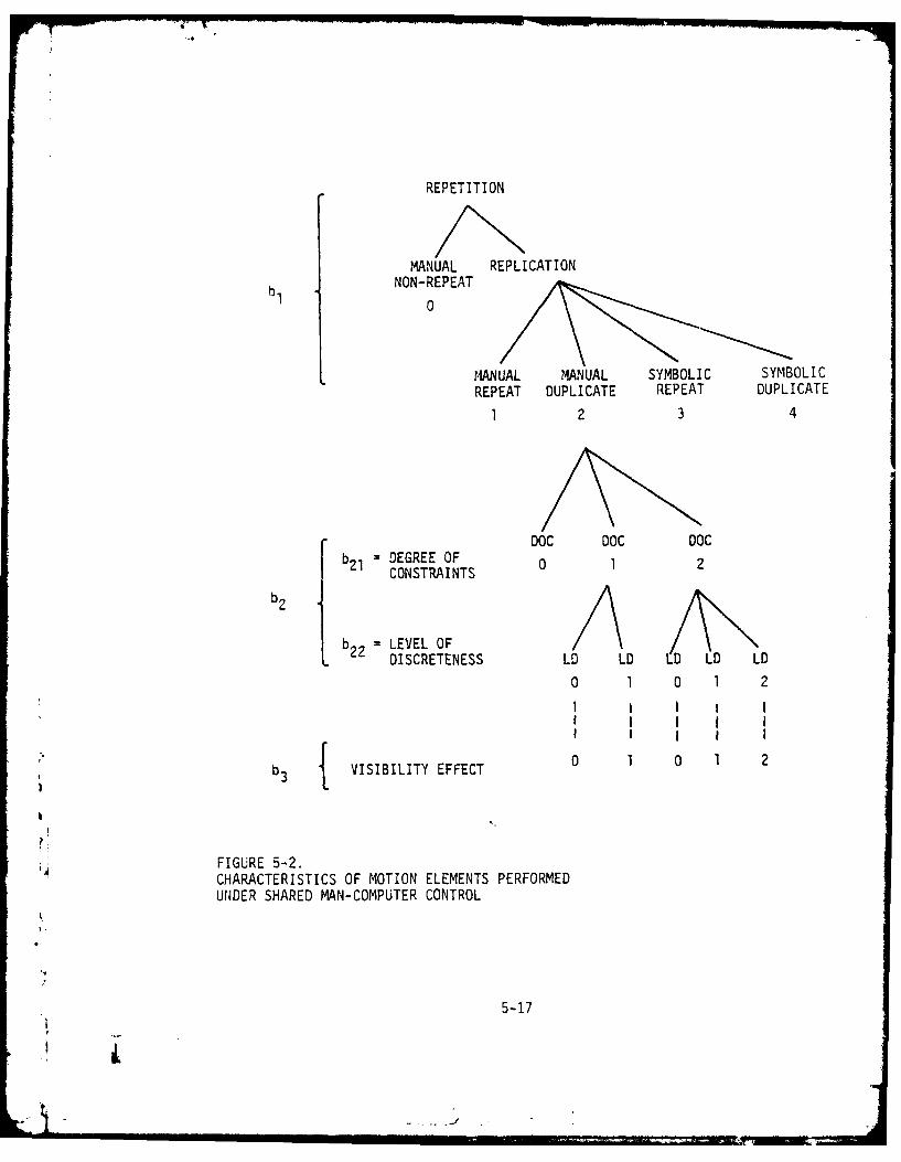
REPETITION
MANUAL REPLICATION
b NON-REPEAT0
MANUAL MANUAL SYMBOLIC SYMBOLICREPEAT DUPLICATE REPEAT DUPLICATE
1 2 3 4
DOC DOC DOC
= DEGREE OF 0 1 2CONSTRAINTS
b LEVEL OFL DISCRETENESS LD LD LO LD LD
0 1 0 1 2I I I I II j I I I
rI I I I I
b3 VISIBILITY EFFECT 0 1 0 1 2
FIGURE 5-2.CHARACTERISTICS OF MOTION ELEMENTS PERFORMEDUNDER SHARED MAN-COMPUTER CONTROL
5-17

(b9 procedural aspects of motion was manually-controlled and not repeated
in any nianner (i.e., b 1 = 0). Performance improvement was expected when
motion could be replicated as (1) repeated (with relative reference in
workspace) or duplicated (with absolute reference); and as (2) manual (with
no symbolic abstraction) or symbolic (with symbolic abstraction). Hence,
there were four combinations of motion replication: manual repeat (b, =1),
manual duplicate (b 1 = 2), symbolic repeat (b, = 3) and symbolic duplicate
(b1 4). Here, the values assigned to b1 represent the relative levels
of performance improvement expected for each type of replication, which
mainly reflects the system (command) contribution.
At the second level, constraint (taxon) aspects of motion elements were
considered. It was considered that major improvements can be achieved
when difficult multi-degree-of-constraint motion could be effectively
discretized into single or low degree-of-constraint motions and duplicated
with the use of computer assisted functions. The combined task-system
effect of constraint discreteness (b 2) can be represented in a simple
additive function of (1) degree of constraints, b 21 ' and (2) level of
discreteness, b 22.
At the third level, environmental aspects of motion elements were considered.
It was noted in the experiment that performance improvement was higher
in degraded visibility than in normal visibility, especially with a task
of high level of discreteness where requirements of visual observation
were greatly reduced with the use of automatic commands. It was then
assumed that visibility effect was differentiated by the level of discrete-
ness only. Other factors may enter the analysis with further expansion of
the tree in more detailed levels. To determine the ratios of time reduction,
the tree of motion analysis can be folded back, with the relevant attri-
butes identified. Table 5-2 presents the calculated values of time reduc-
tion factors for a set of selected motion elements under normal visibility
(a&s) and degraded visibility (a's). These values were used next in the
calculation of execution time.
5-18
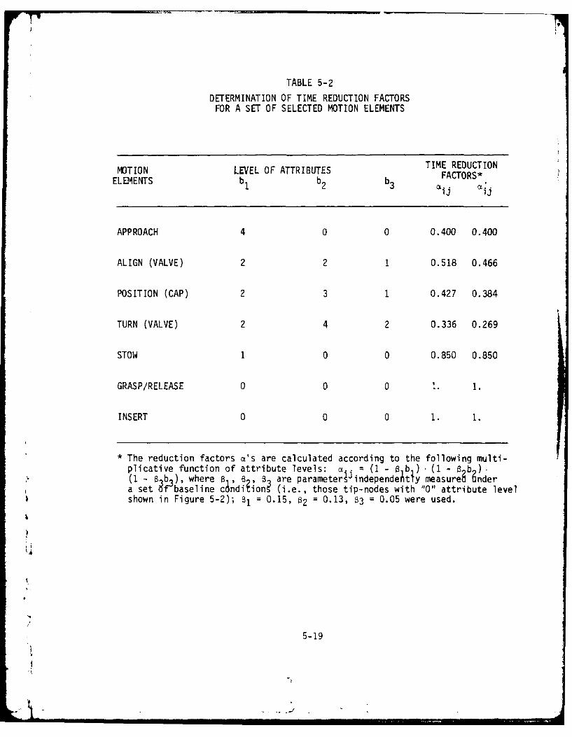
TABLE 5-2
DETERMINATION OF TIME REDUCTION FACTORSFOR A SET OF SELECTED MOTION ELEMENTS
MOTION LEVEL OF ATTRIBUTES TIME REDUCTIONELEMENTS b FACTORS*1 ij i
APPROACH 4 0 0 0.400 0.400
ALIGN (VALVE) 2 2 1 0.518 0.466
POSITION (CAP) 2 3 1 0.427 0.384
TURN (VALVE) 2 4 2 0.336 0.269
STOW 1 0 0 0.850 0.850
GRASP/RELEASE 0 0 0 I. 1.
INSERT 0 0 0 1. 1.
* The reduction factors a's are calculated according to the following multi-plicative function of attribute levels: j : (I - 0 b ) (I - 6 b(I -t ab 3 ), where B , , 8 are parameter independeitly measure; 9ndera set f baseline c~ndiiion (i.e., those tip-nodes with "0" attribute levelshown in Figure 5-2); 81 : 0.15, 82 : 0.13, 83 = 0.05 were used.
5-19

Execution time was calculated for subtask performance under automatic com-
mand using the equation (3) in Figure 5-2. The motion element performancetimes, t i, were taken from results under fixed commiand. Mental decision/
transition times, F-j were estimated from the performarce data under the
automatic cormmand itself. Ideally, these variables should have been
determined independently, if possible sources of data independent of exper-
imental situations were available. Fortunately, since the magnitude of
these variables is rather small (in the order of one to three seconds),
the effect on overall prediction accuracy is small. The results are
summarized in Table 5-3, which also gives the observed execution times
from the experiment for comparison.
The predicted execution times are quite accurate. This can be seen in
Figure 5-3, which plots the predicted versus observed data from Table 5-3
in logarithmic scale. The correlation coefficient was computed and found
to vary from 0.79 to 0.92 for the six subjects.* The root mean square
(RMS) error is 6.2% of the average predicted execution time, which is quite
satisfactory for most practical applications.
The data comparison has provided evidence for the simple additive model
in predicting execution time performance in the traded control mode. As
the verification of the model in task definition and augmented control
mode is relatively straightforward, it appears that the model would beadequate in providing simple prediction. Given the approach used, the
time required for a trained operator to perform a simulated manipulation
task can be predicted to within about 7%1 by a simple additive-multi-
plicative function of task elements and factors. Although the approach
is narrow in requiring the detailed micro-attribute analyses and in being
These values are somewhat inflated due to the method used to determinesome of the parameters, as described in the preceding paragraph.
5-20

TABLE 5-3
CALCULATED AND OBSERVED TASK EXECUTION TIMES
CALCULATED OBSERVED' PREDICTIONTASKS EXECUTION TIME EXECUTION TIME ERROR
(SEC) (SEC)
VALVE CLOSING (NORMAL) 102.54 104.33 ± 27.12 -1.7%
VALVE CLOSING (DEGRADED) 100.04 104.67 ± 16.47 -4.4%
CAP REPLACEMENT (NORMAL) 134.95 127.00 ± 19.22 6.3%
CAP REPLACEMENT (DEGRADED) 171.66 160.84 ± 25.43 6.7%
VALVE OPENING (NORMAL) 74.95 71.83 ± 7.48 4.3%
VALVE OPENING (DEGRADED) 72.12 69.50 ± 7.72 3.8%
STOW (NORMAL) 20.26 20.17 ± 7.96 C.4%
STOW (DEGRADED) 18.42 18.17 ± 7.99 1.4%
+ POPULATION MEAN + STANDARD ERROR FOR SAMPLES OF SIZE 6
5-21

500400
300 .
200
1 5 0-Lu.
0o
80-
< 601
50L-)' 40- VISIBILITY TASK
0 30- NORMAL DEGRADED
/3 U VALVE-CLOSING20 - VALVE-OPENING
7 V CAP-REPLACEMENT fA STOW
10 I I I I I , lI I I I ,10 20 30 40 50 60 80 100 150 200 300 400 500
OBSERVED EXECUTION TIME (SEC) -
k
FIGURE 5-3.PREDICTED VS. OBSERVED TASK EXECUTION TIMES
5-22
,1
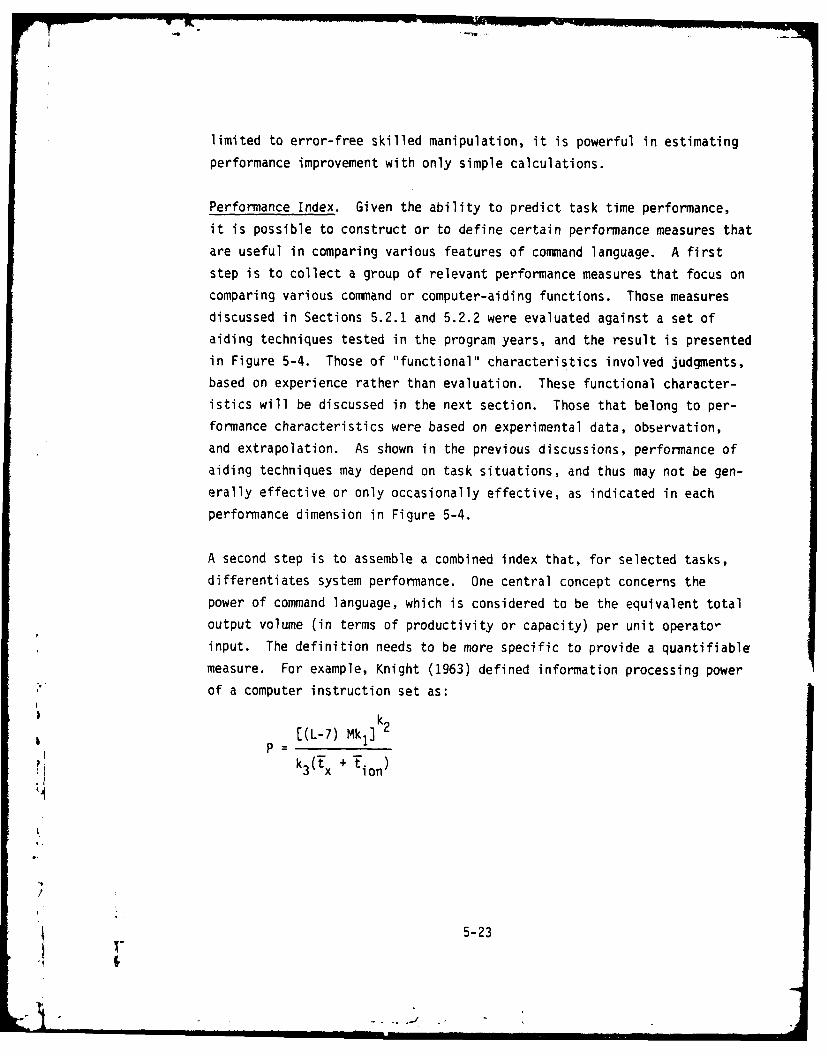
limited to error-free skilled manipulation, it is powerful in estimating
performance improvement with only simple calculations.
Performance Index. Given the ability to predict task time performance,it is possible to construct or to define certain performance measures thatare useful in comparing various features of command language. A firststep is to collect a group of relevant performance measures that focus oncomparing various command or computer-aiding functions. Those measuresdiscussed in Sections 5.2.1 and 5.2.2 were evaluated against a set ofaiding techniques tested in the program years, and the result is presentedin Figure 5-4. Those of "functional" characteristics involved judgments,based on experience rather than evaluation. These functional character-istics will be discussed in the next section. Those that belong to per-formnance characteristics were based on experimental data, observation,and extrapolation. As shown in the previous discussions, performance ofaiding techniques may depend on task situations, and thus may not be gen-erally effective or only occasionally effective, as indicated in each
performance dimension in Figure 5-4.
A second step is to assemble a combined index that, for selected tasks,differentiates system performance. One central concept concerns thepower of command language, which is considered to be the equivalent totaloutput volume (in terms of productivity or capacity) per unit operator-input. The definition needs to be more specific to provide a quantifiablemeasure. For example, Knight (1963) defined information processing powerof a computer instruction set as:
[(L-7) Mk1]
3(x + ion)
5-23

FUNCTIONAL CHARACTERISTICS
Key: Z
H < 60 ms M - MediumL 20 ms T = TrainingVL 5 5 ms P - PreprogramB '16 K Core X Q 1S 8 K Ccre -
H THighL SLow
Resolved Motion Control H S-M - *L L T
Fixed Symbolic Command L S 1-3K L L M T
+ Variable Symbolic Command L S-M 1-3K H H L T,2
+ High - Level Command Structure L S-M 1-3K H H L T,P
Program State Feedback VL S <1K L H M -
Sensor (Force) Monitor L-M S 3-10K L H H -
Symbolic Sensor Graphic M-H B 2-10K L M H T
PERFORMANCE CHARACTERISTICS
Key: /G Generally Effective
0 Occasionally Effective r
Resolved Motion Control - G G - G 0
Fixed Symbolic Command 0 G 0 - 0 - -
+ Variable Symbolic Command G G G - - G G
+ High - Level Command Structure - G G G - G 0
Program State Feedback - - G - 0 - -
Sensor (Force) Monitor - 0 G - G 0
Symbolic Sensor Graphic G 0 G 0 G - 0
k Using servoarm manipulator direct joystick control system (seeAppendix b) as a baseline system
FIGURE 5-1.CHARACTERISTICS OF SAMPLED AIDIING TECHNIQUES
5-24

where L is the instruction length in bits, M is the memory size in words,
t xis the mean instruction execution time, t.io is the mean non-overlapped
1/0 time, k 1 is a coefficient whose value depends on word length, and k2kare constants. This definition of instruction power is useful, but is
hardware-oriented.
Based on the analysis in performance model validation in the last section,
one candidate measure of command language power in manipulation control
can be defined as the ratio of the volume of motion elements (i.e., the
total number of tip nodes expanded by a multi-level tree structure such
as one shown in Figure 5-2) to command definition time (the sum of all d's
in Figure 5-1), or
=(k I k 2 N)L
LIc. (d0 +
j=1 j. 0
where L is the level of command abstraction; N is the total level of dis-
creteness; k 1 and k2are the level and degree (%) of command replicationand repetition, respectively; (d 0 + E 0) is the top-level command definitiontime; c.i are parameters based on command mixes specification and vary within
the range of 1 to 2, with full use of augmented control to full use of
traded control. The power of two command sets can then be compared with
the use of > enchmark tasks using the above formula. As the power index
increases exponentially with L while it only proportionally decreases withL as indicated in the relation described above, it appears that, in most
cases (with sufficiently large N), the high level abstraction is a definite
plus.
5-25
5.3 System Extention and Future Research Needs
5.3.1 Extension of TOSC Language. From previous analysis, it becomes
immuediately apparent that current system performance could be improved
with the features described in the following added to the system. For-
tunately, current implementation allows immediate extension of the follow-
ing features due to modularly-structured software design:
(1) Increased number of low-level automated functions (as
fixed primitives).
(a) Localized sensor-based steering.
(b Force compliance.
(2) Improved replica control.
(a) Trajectory calculation-computational overhead.
(b) Relative geometry (point/path).
(3) Flexible command organization and chaining.
(a) Conditioned construction of chain.
(b) Control looping. -
(4) Expandability -- allowing for: '
(a) Additional physical constraints.
(b) Additional force/contact constraints.(c) Increased automatic/learning functions.jMd Increased database.
5-26

(5) Data compactness.
(a) Formal grammatical rules.
(b) Formal state definition -- command, sensors, control
mode, effector.
(c) Relative displacement, orientation, and distance to
objects.
5.3.2 Future Research Needs. This section summarizes what we believe
to be primary research needs in machine-to-man communication in advanced
teleoperation:
(1) How can spatial information best be presented; conversely,
will graphic geometric feedback results in improved task
performance comapred to video feedback of limited quality
and bandwidth? Performance must be compared in the speed
and accuracy achievable, the complexity of tasks that can
be accomplished, the unburdening provided, and the communi-
cation bandwidth required.
(2) In what conditions will geometric feedback with predictive/
directive information results in improved performance
compared to full bandwidth video?
(3) What level of detail and what form of spatial presentation
is essential for various levels of control automation? The
evaluation. may use a set of representative underwater
manipulation tasks with varying degrees of complexity,bdifferent viewing orientations and scope, and varying
response times.
5-27

(4) What are the best performance measures for the man-machine
information system and its several components? Is there a
suitable overall criteria measure? Consideration includes
the following measures:
Task Performance
(a) Speed - time to complete.
(b) Accuracy - contact errors or RMS accuracy.
Task Difficulty
(a) Complexity - number of task elements.
(b) Dynamics - movement of elements.
(c) Orientation - presence of reference cues.
(d) Intermittency - blanking of communications.
(e) Turbidity - degradation of communications by noise
(S/N).
Unburdening I
(a) Secondary task capability. I(b) Percent of control by machine.
(c) Difficulty of task (capability of man-machine system).
System Performance
)
(a) Bandwidth required. -
(b) Response time. ,
(c) Training time.
5-28
rl
"'l lll I I I I I

(5) What are the relationships between mode of presentation,
context, content, and task performance measures?
(6) A better empirical database to specify how performance
degrades as a correspondence between sensor (range, resolu-
tion), communication (noise, band-limited, transmission
rate), and local presentati'n (resolution, delay) degrades.
)
A
/
' 5-29
6. REFERENCES
Adolfson, J. and Berghage, T. Perception and Performance Underwater. NewYork: John Wiley and Sons, 1974.
Ambler, A.P., Barrow, H.G., Brown, C.M., Burstell, R.M., and Popplestone,R.J. A Versatile Computer-Controlled Assembly System. Third InternationalJoint Conference on Artificial Intelligence, Stanford, 1973:298-307.
Ashford, F. The Aesthetics of Engineering Design. Business Books, Ltd.,London, 1969.
Battelle. U.S. Navy Diving Gas Manual, Washington, DC, U.S. Navy Supervisorof Diving (1971) (Navships 0994-003-7010).
Battelle. Underwater Vehicle Work Systems and Tool Suits. Columbus, Ohio,1976.
Bejczy, A.K, and Paine, G. Displays for Supervisory Control of Maripulators.Proceedings of Thirteenth Annual Conference on Manual Control, MIT, Cambridge,MA, June 1977.
Bennett, J. L. The User Interface in Interactive Systems. In Annual Reviewof Information Science and Technology, C. A. Cuadra (Ed.), Vol. 7, Washington,DC: American Society for Information Science, 1972:159-196.
Berson, B.L., Crooks, W.H., Shaket, E., and Weltman, G. Man-Machine Communi-cation in Computer-Aided Manipulation. Perceptronics, Inc. (Woodland Hills,CA) Technical Report PATR-1034-77-3/1, March 1977.
Bertsche, W.R., Logan, K.P., Pesch, A.J. and Wernli, R.L. Evaluation of theDesign and Undersea Work Capacity of the Work Systems Package. NOSC TR 214,U.S. Navy, April 1978.
Bertsekas, D.P. and Rhodes, I.B. On the Minimax Reachability of Target Setsand Target Tubes, Automatica, 1971, 7:233-24.7.
Bien, A. and McDonough, P.J. Naval Application of Man-In-The-Sea Concepts.SRI NWRC 7000-212, 1968.
Bryant, S.B. and Funk, C.J. Performance study of present and near-futurediving viewing systems. Naval Undersea Center, San Diego, CA, July 1972(NUC-TP-302).
Busby, R.F. Review of Manned Submersibles Design, Operation Safety and*, Instrumentation. Report, R. Frank Busby Associates, Arlington, VA, July 1978.
6-1

Busby, R.F. Underwater Inspection/Testing/Monitoring of Offshore Structures.Ocean Engineering, 1979 6(4):355-491.
Carbonell, J.R. Artificial Intelligence and Large Interactive Man ComputerSystems. 1971 IEEE System, Man, and Cybernetics Society Annual SymposiumRecord, October 1971, Anaheim, CA, pp. 167-172.
Card, S.K., Moran, T.P., and Newell, A. The keystroke-level model for userperformance time with interactive systems. Report SSL-79-1, Xerox Palo AltoResearch Center, Palo Alto, CA, March 1979.
Cevveny, R.P. and Knight, K.E. Performance of minicomputers. Proceedingsof 2nd Texas Conference on Computer Systems, November 1973, 28.1-28.7.
Chapanis, A. and Lockhead, G. A test of the effectiveness of sensor linesshowing linkages between displays and controls. Human Factors, 1965, 7(3):219-229.
Chu, Y. Adaptive Allocation of Decision Making Responsibility Between Humanand Computer in Multi-Task Situations, Ph.D. Thesis, University of Illinois(Urbana, IL), 1978.
Chu, Y. and Rouse, W.B. Adaptive Allocation of Decision Making Responsibilitybetween Human and Computer in Multi-task Situations. IEEE Trans. Syst. ManCybern., December 1979, SMC-9(12):769-78.
Corker, K., Mishkin, A. and Lyman, J. Achievement of a sense of operatorpresence in remote manipulation. Report Biotechnology Laboratory, UCLA, 1980.
Corkill, D.D. An organizational approach to planning in distributed problemsolving systems. COINS Technical Report 80-13, Computer and InformationScience, University of Massachusetts, Amherst, MA, May 1980.
Corliss, W.R. and Johnsen, E.G. Teleoperator Controls, NASA SP-5070, 1968.
Crooks, W.H., Shaket, E., and Alperovitch, Y. M!Kn-Machine Communication inComputer-Aided Remote Manipulation. 7erceptronics, Inc. (Woodland Hills, CA)March 1978.
Crooks, W.H., Shaket, E., Chu, Y., and Alperovitch, Y. Man-Machine Communi-cation in Remote Manipulation. Technical Report, Perceptronics, Inc. (Wood-
*land hills, CA) March 1979.
Crooks, W.H., Steeb, R., and Weltman, G. Design of a Video System ProvidingOptimal Visual Information for Controlling Payload and Experiment Operationswith Television. Design Report PTR-1021-74-10/28, Perceptronics, Inc.,(Woodland Hills, CA) October 1974.
6-
6-2
Dijkstra, E.W. Structured Programming. Chapter 1, Academic Press, 1972.
Drenning, R.P. Manipulator/Deep Ocean Tool Work System. Westinghouse OceanResearch and Engineering Center, Annapolis, MD, undated paper.
Engel, S.E. and Granda, R.E. Guidelines for Man/Display Interfaces. Pough-keepsie Laboratory, IBM Technical Report TR002720, December 1975.
Estabrook, N.B. An Underwater Work Systems Package, Proc. 2nd Conf. RemotelyManned Systems (RMS), Los Angeles, CA, June 9-11, 1975.
Fahlman, S.E. A Planning System for Robot Construction Tasks. ArtificialIntelligence, 1974, 5:1-50.
Falkoff, A. and Iverson, K.E. The Design of APL. IBM Journal of Researchand Development, July 1973.
Ferrari, D. Computer Systems Performance Evaluation. Englewood Cliffs, NJ:Prentice-Hall, 1978.
Ferrell, W.R. Command Language for Supervisory Control of Remote Manipulation.In Remotely Manned Ssytems, E. Heer (Ed.), California Institute of Technology,1973.
Ferrell, W.R. Remote Manipulation with Transmission Delay. IEEE Trans.Human Factors in Electronics, 1965, HFE-6:24-32.
Ferrell, W.R. and Sheridan, T.B. Supervisory Control of Remote Manipulation.IEEE Spectrum, October 1967:81-88.
Fikes, R.E. and Nilsson, N.J. STRIPS: A New Approach to the Application ofTheorem Proving to Problem Solving. Artificial Intelligence, 1971, 2:189-208.
Finkel, R., Taylor, R., Bolles, R., Paul, R., and Feldman, J. AL, A Pro-gramming System for Automation. Stanford Artificial Intelligence Laboratory(Stanford, CA) Memo AIM-243 (STAN-CS-74-456), November 1974.
Fitts, P.M. and Seeger, C.M. S-R compatibility: spatial characteristics ofstimulus and response codes. J. of Experimental Psych. 48:199-210, 1953.
Foley, J.D. and Wallace, V.L. The Art of Natural Graphic Man-Machine Con-versation. Proceedings of the IEEE, June 1975, 62(4).
Fleishman, E. A. Toward a Taxonomy of Human Performance. American Psycholo-gist, December 1975:1127-49.
6-3
i

7'5
Freedy, A. Learning Control in Remote Manipulator and Robot Systems inLearning Systems, K. S. Fu (Ed.) ASME publication, 1973.
Grady, W.E. and Fridge, D.S. How to Select Diving Systems in Off-shoreApplications, Ocean Industry, April 1978:51-56.
Goertz, R.C. Mechanical Master-Slave Manipulator. Nucleonics, November1954, 12:45-46.
Heckman, P., and McCracken, H. An Untethered, Unmanned Submersible, Ocean79 Proceedings, San Diego, CA, September 1979.
Hill, J.W. Study to Design and Develop Remote Manipulator Systems. Twomeasures of performance in a peg-in-hole manipulator task with force feed-back. Proceedings: Thirteenth Annual Conference on Manual Control, M.I.T.,1977.
Hill, J.W. and Sword, A.J. Study to Design and Develop Improved RemoteManipulator Systems. NASA CR 2238, Stanford Research Institute, April, 1973.
Jagacinski, R.J., Repperger, D.W., Moran, M.S., Ward, S.L. and Glass, B.Fitt's Law and the Microstructure of Rapid Discrete Movements. Journal ofExperimental Psychology: Human Perception and Performance, 1980, 6(2):309-320.
Jet Propulsion Lab. Machine Intelligence and Robotics: Report of the NASAStudy Group. Jet Propulsion Laboratory 730-51, California Institute ofTechnology, September 1979.
Johannsen, G. and Rouse, W.B. Prospects of a mathematical theory of human Ibehavior in complex man-machine system tasks. Proceedings of the FourteenthAnnual Conference on Manual Control, University of Southern California, April1978. rKennedy, T.C.S. The Design of Interactive Procedures for Man-MachineCommunication. International Journal of Man-Machine Studies. 1974, 6:309-334.
Kinney, J.S., et al. Effects of Turbidity on Judgements of Distance Under-water. Perceptual and Motor Skills, 1969, 28:331-333.
Knight, K.E. A study of technological innovation: The evolution of digitalcomputers. Ph.D. Thesis, Carnegie Institute of Technology, Pittsburgh, PA,November 1963.
Lesser, V.R. and Corkill, D.D. Functionally Accurate Cooperative Distri-buted Systems. Proceedings of IEEE 1979 Conference on Cybernetics andSociety, Denver, CO, October 1979, pp. 346-53.
6-4
.. o .J
-- I

Licklider, J.C.R. Man-computer symbiosis. IEEE Trans. on Human Factors inElectron. HFE-1(1):4-11, March 1960.
Lozamo-Perez, T. and Winston, P.H. LAMA: A Language for Automatic MechanicalAssembly. (Boston, MA) Fifth International Joint Conference on ArtificialIntelligence. August 1977:710-716.
Martin, J. Design of man-computer dialogues. Englewood Cliffs, NJ: Prentice-Hall, 1973.
McGovern, D.E. An Investigation of supervisory control of manipulation.Mechanism and Machine Theory. 1977, 12.
McGovern, D.E. Factors Affecting Control Allocation for Augmented RemoteManipulation. Ph.D. Dissertation, Stanford University, 1974.
Miller, L.A. and Thomas, J.C. Jr. Behavioral Issues in the Use of InteractiveSystems. International Journal of Man Machine Systems, 1977, 9:509-536.
McCormick, E.J. Human Factors Engineering. McGraw-Hill, 1970.
Minsky, M. Automation and Artificial Intelligence in Science, Technology,and Modern Navy. Thirtieth Anniversary 1946-1976. E. I. Salkovitz (Ed.)Office of Naval Research, Department of the Navy, Arlington, VA.
Moray, N. Attention, Control, and Sampling Behavior. In T.B. Sheridanand G. Johannson (Eds.) Monitoring Behavior and Supervisory Control, New York:Plenum, 1976.
Nevin, J.L. and Whitney, D.C. Computer Controlled Assembly. ScientificAmerican, January 1978.
Nilsson, N.J. Principles of Artificial Intelligence. Palo Alto, CA: TiogaPublishing, 1980.
Ocean Industry. New Concept: Modular Offshore Services. August 1978: 56-57.
Ocean Systems, Inc. What do those expensive divers really do? OffshoreServices Magazine, September 1977:78-81.
Ocean Technology Department, NOSC. Ocean Technology--A Digest. NOSC Tech-nical Document 149, March 1978.
Paul, R. Evaluation of Manipulator Control Programming Languages. IEEEEighteenth Conference on Decision and Control, December 1979, Fort Lauderdale,FL.
6
6-5
1
1-

Paul, R. Trajectory Control of a Computer Arm. IJCAI, 1971:385-390.
Paul, R.L. Performance Measurement and Evaluation of General Purpose Mani-pulators. Proceedings of Second International Joint Conference on Arti-ficial Intelligence, London, 1971:385-390.
Pesch, A.J. and Bertsche, W.R. Performance measurement for undersea systems.In T. B. Sheridan (Ed.) Performance Evaluation of Programmable Robots andManipulators, N.B.S. SP-459, 1976.
Pesch, A.J., Klepser, et al. Capabilities of Operators as Divers: SubmersibleManipulator Controllers in Undersea Tasks. Groton, CT, General DynamicsCorporation, AD-716532, June 1970.
Pesch, A.J., Hill, R.G., and Allen, F.L. At-Sea Operator Performance ofSmall Submersible Manipulators. General Dynamics Electronic Boat DivisionTechnical Report No. U-413-71-031, 1971.
Ramsey, H.R. and Atwood, M.E. Human Factors in Computer Systems: A Reviewof Literature, Technical Report SAI-79-111-DEN, Science Applications, Inc.Englewood, CO, September 1979.
Ranadive, V. Video Resolution, Frame Rate and Gray Scale Tradeoffs UnderLimited Bandwidth for Undersea Teleoperation. Technical Report, Man-machineSystems Laboratory, MIT, September 1979.
Roscoe, S.N. Airborne displays for flight and navigation. Human Factors10(4):321-332, 1968.
Rouse, W.B. System Engineering Models of Human-Machine Interaction. NewYork, New York: Elsevier North Holland, 1980.
Rouse, W.B. Design of Man-computer Interface for On-line Interactive Systems.Proceedings of the IEEE, June 1975, 63(6):847-857.
Rechnitzer, A.B. and Sutter, W. Naval Applications of Remote Manipulation,in E. Heer (Ed.) Remotely Manned Systems, California Institute of Technology, .
1973.
Sacerdoti, E.D. Problem Solving Tactics. Technical Note 189, SRI Inter-national, Menlo Park, CA, July 1979.
Sacerdoti, E.D. Planning in a Hierarchy of Abstraction Spaces. ThirdInternational Joint Conference on AI, 1973:412-422.
Sacerdoti, E.D. A Structure for Plans and Behavior. Stanford ResearchInstitute Artificial Intelligence Center, Technical Note 109, 1975.
6-6

Schneider, M.H. Task Analysis for Undersea Manipulators. M.S. Thesis, MIT,1977.
Schutz, H.G. An evaluation of formats for graphic trend displays--ExperimentII. Human Factors, 1961, 3(2):99-107.
Schweppe, F.C. Uncertain Dynamic Systems. Englewood Cliffs, NY: Prentice-Hall, 1973.
Seireg, A. and Kassem, E. Design considerations for a computer controlledplatform to support working divers. Ocean '77 Proceedings of Third AnnualCombined Conference of IEEE and MTS, 1977.
Sheridan, T.B., Brooks, T.L., Takahashi, M., and Ranadive, V. How to Talkto a Robot. Proceedings of IEEE International Conference on Cybernetics andSociety in Denver, CO, October 1979:33-35.
Sheridan, T.B. Evaluation of Tools and Tasks: Reflections on the Problemof Specifying Robot/Manipulative Performance. In T.B. Sheridan (Ed.) Per-formance Evaluations of Programmable Robots and Manipualtors, NBS SP459,October 1976.
Sheridan, T.B. and Verplank, W.L. Human and Computer Control of UnderseaTeleoperators. Man-Machine System Laboratory, MIT, 1978.
Shilling, C.W., Werts, M.F. and Schandelmeier, N.R. (Eds.) The UnderwaterHandbook. New York: Plenum Press, 1976.
Schneiderman, B. Software Psychology. Cambridge, MA: Winthrop Publisher,1980.
Steeb, R., Artof, M., Crooks, W.H., and Weltman, G. Man/machine Interactionin Adaptive Computer-aided Control: Final Report. Perceptronics, Inc.,(Woodland Hills, CA) NR 196-118, December 1975.
Steeb, R., Chu, Y., Clark, C., Alperovitch, Y. and Freedy, A. AdaptiveEstimation of Information Values in Continuous Decision Making and Controlof Advanced Aircraft. Perceptronics, Inc. (Woodland Hills, CA) TechnicalRepot PATR-1037-79-6, June 1979.
Steeb, R., Weltman, G. and Freedy, A. Man-Machine Interaction in AdaptiveComputer Aided Control. Human Factors Guidelines. Perceptronics, Inc.
b(Woodland Hills, CA) Technical Report PATR-1008-76-1/31, January 1976.
Talkington, H.R. Remotely Manned Undersea Work Systems at Naval Ocean SystemsCenter. Naval Ocean Systems Center, San Diego, CA, 1978.
6
~6-7
Tierney, J. P. and Walrod, R.A. Development of an electronic control systemfor remote controlled underwater vehicles. Ocean '77 Proceedings of ThirdAnnual Combined Conference of IEEE and MTS, 1977.
Treu, S. Interactive Command Language Design Based on Required Mental Work.International Journal of Man-Machine Studies. 1975, 7:135-149.
Vaughan, W.S. An Analysis of Environmental and Perceptual Determinants ofDisplay Legibility Underwater. Oceanautics, Inc. Landover, MD, April 1976.
Vaughan, W.S., Glass, R.A. and Williams, J. Legibility of Self-Lum;nousDisplay Variations Viewed Through Artificially Turbid Waters. Oceanautics,Inc., Annapolis, MD, August 1977.
Vaughan, W.S., Jr., Glass, R.A., and Williams, J. Peripheral detection andidentification of self-luminous display variations in 'Ocean' and 'Harbor'viewing environments. Annapolis, MD: Oceanautics, Inc., November 1978.
Vaughan, W.S. and Mavor, A.S. Behavioral characteristics of men in the per-formance of some decision-making task components. Ergonomics, 1972, 15(3):267-277.
Verplank, W. L. Symbolic and Analogic Command Hardware for Computer-AidedManipulation. M.S. Thesis, MIT, 1967.
Verplank, W.L. Is There an Optimal Workload in Manual Control? Ph.D. Thesis,MIT, August 1977. ,
Verplank, W.L. Display Aids for Remote Control of Untethered UnderseaVehicles,. Proceedings of Fourth Annual Combined Conference of IEEE and MTS, !September 1978.
Vertut, J. Experience and remarks on manipulator evaluation. In T. B.Sheridan (ED.) Performance Evaluation of Programmable Robots and Manipulators.N.B.S. SP-459, 1976.
Weissman, S.J. On a Computer System for Planning and Execution in IncompletelySpecified Environments. Ph.D. Dissertation, Unviersity of Illinois at Urbana-Champaign, 1976.
Whitney, D.E. (a). StatE space models of remote manipulation tasks. IEEETransactions on Automatic Control, 1969, AC-14(6).
Whitney, D.E. (b). Resolved motion rate control of manipulators and humanprostheses. IEEE Transactions on Man Machine Systems, 1969, MI4S-10(2).
6-8
,I

Whitney, D.E., Watson, P.C., Drake, S.H. and Simunovic, S.N. Robot andManipulator Control by Exteroceptive Sensors. Proceedings of Joint Auto-matic Control Conference, June 1977:155-163.
6-9
.1
'°" .... .. .~ " -"2

APPENDIX A
SYSTEM APPLICATION GUIDELINES
S L
iiinllI
- ~ -- -- , -. .. ..

SYSTEM APPLICATION GUIDELINES
1. Overview
The program research has resulted in a number of analytic and experimental
findings. This section is a compilation of those findings arranged bytopical area. The intent is to provide a set of guidelines to assistdesigners of upcoming systems and to provide a framework within which
subsequent findings can be inserted.
2. Application Areas
We have found that hierarchical, procedural network-based, command languagedesign methodology has primary application in systems with the following
characteri stics:
(1) Remote or decentralized communication and control.(2) Bandwidth-limited or multiple-information sources.
(3) Supervisory control of systems with extensive autonomy.(4) Local and remote sites computational capability.(5) Overload operator (with complex and time-extended visual and
pre-decision tasks).
Among the types of systems sharing these characteristics are remote con-trolled vehicle or subsystem platforms, central command of distributedintelligent systems, teleconferencing and interactive telaprocessing
systems.
4 The area showing the greatest immediate application in current Navy systemsis that of advanced teleoperator control in a free-swimming submersible ora remote control vehicle. These systems already have a substantial amount
A-i

of automation, high information and control task load, remote communication
and distributed processing, and critical man-machine interaction require-
ments.
3. Design of Multi-Mode Communication
The study suggests the following design principles and steps that should
be used in multi-mode, supervisory control communication language design.
(1) Analysis of task.
(a) Identify a complete set of behavioral elements of tasks.
(b) Identify repeated subtasks and discrete subtasks.
(c) Classify subtasks along major dimensions of taxon in-
formation requirements: precision, speed, accuracy,
complexity uncertainty and simultaneity.
(d) Classify overall tasks along major dimensions of pro- Icedural requirements: abstraction, parallelism, control,
uncertainty, and uniformity.
(2) Analog primitive determination.
(a) Determine the required degree-of-freedom and number of
analog inputs needed concurrently.
(b) Determine the need for indexing or multiple mode analog
input.
(c) Determine the analog input devices and their assignment.
b
(3) Symbolic primitives determination.
4
(a) Define fixed primitives to correspond to repeated and
discrete subtasks in lb.
A-2

(b) Determine parameters requirements for such fixed primi-
tives according to taxon requirements in Ic.
(c) Define variable primitives screened according to taxon
requirements in ic.
(4) Composite organization.
(a) Determine analogic elements for composite organization
(e.g., Paths) with facilities to define, label, modify,
and display them.
(b) Determine symbolic elements for composite organization
(e.g., Chains) with corresponding facilities to define,
label, modify and display them.
(c) Determine scope of taxon information within each com-
posite element.
(5) Command syntax structure.
(a) Define atomic level of sentence structure. Use con-
strained, standardized language used in everyday opera-
tion.
(b) Define autonomous, computer-controlled primitives and
special primitives. Minimize the number of verbs and
nouns.
(6) Command interface design.
(a) Define as integrated symbolic and analogic interface tok correspond physically to the syntax structure in 5.
(b) Provide conceptual continuity through tactile, visual
and contextual continuity.
(c) Provide immediate perceivable response and feedback.
A
bi A-3
jl

(7) Interaction protocol design.
(a) Provide facilities for smooth transitions between control
modes and command activation levels; including a defini-
ion capability, a labeling capability, a display for
review capability and editing capability, an activating
procedure, and a progress display capability.
(b) Initiate delegation of the appropriate performer between
human or computer.
(c) Allow for queueing of input commands and natural trans-
fer between definition mode and execution mode.
(8) Feedback format. I
(a) Use consistent structure and level-of-detail between
command and feedback. I(b) Provide integrated display of taxon and procedure infor-
mation including machine and program states, message Iin task progress, and sensor-event reports.
4. System Performance Analysis
4.1 Overall System Performance. The overall performance measure of a
complex manipulation task is normally gauged using a combination of indices
such as speed, accuracy, error rates, and capacity. For simplicity in explor-
atory studies, it is possible to use independent measures of speed and
error rate as figure of merits by assigning accuracy and capacity require-
ments into discrete categories and allowing subjective trade-offs between
speed and error rates. Much of the work on which these guidelines are
A-4

based used such a method. The aiding actually provided to the human opera-
tor can be estimated in two ways:
(1) Increased system performance. The difference in overall
system performance with and without aiding gives a measure
of the system improvement. However, this performe,,Le gain
does not reflect the unburdening provided by aiding.
(2) Unburdening. The unburdening of the operator may be measured
by subjective estimation or by a change in secondary task
performance with and without aiding. The formal approach is
used more often than the latter in the study of manipulator
control, mainly due to the problems on stability and inter-
ference of primary task performance in the use of a standard
secondary task. Other alternatives, but with less sensitive
measures of unburdening, are the reduction of operator control
and execution time, dec, se in number of degree-of-freedom
to be controlled simultaneois'y, and the reduction in pro-
cedural variability and information complexity.
4.2 Performance of Computer-Aiding Techniques
The effectiveness of various aiding techniques toward successful manipula-
tion can be evaluated by improved performance measures mentioned above,
checks of operator acceptance, reduced system consumption, and increased
capability. As the first two issues are our major concern, additional
measures of performance improvement should be considered. In the augmented
b(serial) control, the additional control quality measures determined from
estimated variations from average performance may be used. These include
time, error rate, and accuracy measures, etc. In the programming (parallel)
cuntrol, the additional performance measures should include programming
A-5

overhead, and quality in programmed repetition (replicability). In a
high-level command mode, important factors are command definition overhead
and perceived command complexity. In a communicaion level, additional
measures may include transition (mode switching or responsibility transfer)
overhead, percent control allocation and frequency of conflict in alloca-
tion decision, etc. In general, these additional measures can be trans-
lated as functional characteristics of various aiding techniques, as
follows:
(1) Predicted performance--prescribed mean and variations in
standard performance.
(2) Resource requirements--processing time, space and hardware/
software interface.
(3) Interface complexity--perceived complexity in command
structure.
(4) Replicability--probability of successful repetition.
(5) Information (taxon and procedure) requirements.
(6) Extra effort in preprogramming--preprogramming and definition Ioverhead.
(7) Extra effort in interaction--switching and transfer costs.
4.3 Subjective Measures
The attitude of operators toward their interaction with the computer aiding
system can be examined in structured form by means of rating scales and in
free form through voluntary comments and experimenter observations. Rat-
ing scale judgments should be taken after an experimental sequence is
completed, rather than interrupting the continuity of the task with interim
ratings. Scales that have been found to be useful are:
(1) Com-.etition/Cooperation--To what extent was the interaction
characterized by conflict?
A-6

(2) Aiding--How much unburdening did the machine provide about
th= dimensions of control simultaneity, complexity,
uncertainty, and dexterity?
(3) Relative Effectiveness--What are your estimates of the
machine's and your own quality of performance?
(4) Automation Predictability--What proportion of the procedural
and spatial preprogramming was expected?
(5) Satisfaction--How satisfied were you with your own and with
the machine's performance?
5. Task-Oriented Supervisory Control System Evaluation
5.1 Overview
The model used to describe the role of a man-machine command language in a
supervisory controlled manipulator is an adaptation of the concept of
procedural net, which was developed by Sacerdoti (1973 and 1975) to repre-
sent plans of manipulative actions. Using this representation, a problem
domain is described as a hierarchy of procedural nets, each representing
some subtask in the problem domain in terms of its goal, its functional
elements, and their relation to the environment. This information is
organized as a combination of data structures and procedural information
in the procedural net. In this study we have adapted this model, believed
compatible with the human perception of a complex task, to be a medium for
communication of such tasks between dn operator and the manipulative
mechanism. Using this model as a base, principles for language organizatior,
features, and communication protocol were derived. The model further makes
clear the role of the human operator in the supervisory control loop and
the functions :hat should be performed by an assisting computer placed in
the control loop. This section presents a list of factors and issues dis-
cussed in the previous chapters related to the design and evaluation of a
shared man-computer communication system.
A-7

p
5.2 Task-Oriented Supervisory Control Language (TOSC) Methodology
A. Preliminary Design Principles
(1) Use task and concept oriented commands.
(a) Sentence structure.
(b) Special purpose keyboard and joysticks.
(c) "Chains" as concepts at varous task levels.
(d) Concept definition capability.
(2) Use hierarchical task organization.
(a) Allow for communication at highest symbolic level.
(b) Allow for suitable level of plan detail.
(c) Allow for manual backup and mixed initiative.
(3) Allow for mixed initiative. I
(a) Allow for smooth control transitions between man and
machine.
(b) Initiate delegation to the better performer between
operator or computer.
(c) Provide feedback of system and task status.
(4) Provide concept definition capability.
(a) Constrained standardized language.
(b) Autonomous computer controlled primitives and special
primitives.
(c) "Chains" as conceptual units corresponding to task
elements.
A-8
tI

(5) Smooth control transition.
(a) Machine relinquishment of control to operator during
chain execution.
(b) Manual override in automatic mode.
(c) Computer monitor and warning preventing impact and
reflex.
(d) Real-time manual modification to computer controlled
action.
(6) Provide feedback of system and task status.
(a) Machine status - manipulator and subsystem.
(b) Program state - command definition and execution.
(c) Task in progress - current activity and sensor control.
(d) Environment state - work space and environmental sensor
data.
(7) Provide tactile, visual and contextual continuity.
(a) Natural grouping and flow of motion for operating
tactile input devices.
(b) Information arrangement providing continuous eye move-
ment throughout sentence expression.
(c) Immediate perceivable responses and feedback to rein-
force the effect of action sequence.
(8) Consistent structure of language and feedback.
(9) Provide suitable levels of error recovery, redundancy and
simplicity in dialog.
A-9
.- I

B. TOSCL Features (Compared with Sacerdoti's Procedural Net Model)
(1) Supervisory planning by operator instead of machine.
(2) No preprogramming or pre-structuring.
(3) On-line real-time programing.
(4) Bottom-up definition by user.
(5) Added communication aspects: sentence structure, dedicated
keyboard, and multi-mode feedback, etc.
(6) Added analog input, dynamic queue.
(7) Eliminate parallel (concurrent) machine activities.
(8) Eliminate explicit goal statements for each node.
(9) No criticism and checking in formal procedure.
C. TOSCL Current Implementation Characteristics
(1) Analogic and symbolic primitives.
(2) Specific versus general commands.
(3) Direct versus resolved motion control.
(4) Sentence versus programming structure of command.
(5) Hierarchical versus event sequential structures of procedure.
(6) Task-oriented versus program-oriented communication.
5.3 Command Language Characteristics
A. General Command Structures
(1) Abstraction.
(a) Low-level versus high-level.
(b) General versus specific.
A-1
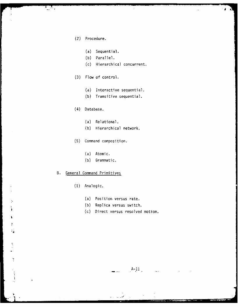
(2) Procedure.
(a) Sequential.
(b) Parallel.
(c) Hierarchical concurrent.
(3) Flow of control.
(a) Interactive sequential.
(b) Transitive sequential.
(4) Database.
(a) Relational.
(b) Hierarchical network.
(5) Command composition.
(a) Atomic.
(b) Grammatic.
B. General Command Primitives
(1) Analogic.
(a) Position versus rate.
(b) Replica versus switch.
(c) Direct versus resolved motion.
A-1
*Ail
• A-II

(2) Fixed symbolic.
(a) Spatial points.
(b) Paths.
(c) Low-level motions.
(d) Automatic functions.
(3) Variable symbolic.
(a) Command building.
(b) Protocol control.
(c) Index and quantifier.
(4) Expandability - allowing for--
(a) Additional physical contraints.
(b) Additional force/contact constraints.
(c) Increased definition learning functions.
(d) Increased database.
(5) Data compactness.
(a) Formal grammatical rules.
(b) Formal state definition - command, sensors, control
mode, effector.
(c) Relative displacement, orientation, and distance to
objects.
(6) Information processing power of a command set, P, is given by.
AL_(k 1 k 2 N)L
k k3 (tfe + f
A-i12

Where:
L highest level of command abstraction.
N number of fixed primitive commands.
t e: execution (processing) time of instruction.
td: non-overlap definition time.
k I coefficient depends on degree of repetitiveness.
k2: coefficient depends on percent of user-definedcommand.
k3: parameter based on command mixes specification.
6. Application Considerations in the Free-Swimming Teleoperator Control
6.1 Overview
Much of the shared man-computer communication and control methodology
developed in this program may be demonstrated in the context of tethered
or free-swimming teleoperator operations. The possibility of mapping the
developed methodology into a prototype interface design incorporated with
the RCV platform has recently been investigated. The study presented in
this section offers an opportunity to examine the issues and applicability
of various command and communication design techniques derived earlier.
The test-bed platform under consideration is the free-swimming submersible
or remote controlled vehicles developed in Navy laboratories during the
past few years. A primary example is a recently commenced development of
unmanned free-swimming vehicles being developed at Naval Ocean System
Center. The submersible, as currently configured, has a modular construc-
tion which allows expansion to accommodate additional payloads and new
sensor systems. The vehicle is microprocessor-controlled and is capable
of following preprogrammed instructions. It can be programmed via a com-
puter console and an umbilical cable which is disconnected after the initial
A-13* ... . . ." o ".
programming phase. Additional control and data sensors will be added
(Heckman and McCracken, 1979). These include an acoustic control link,
an acoustic slow-scan television link, and a fiber optic communication
link. The end result will be a system which is relatively inexpensive,
free from cable drag and cable-handling problems and one which shouid
automously perform rudimentary tasks without direct operator control
(Talkington, 1978).
As several studies of underwater tasks analysis (e.g., Bien and McDonough,
1971; Busby, 1979) have concluded, most operations require rudimentary
manipulation capability, even in simple inspection and survey tasks. And
indeed, this rudimentary manipulation capability accomplishes a major
portion of typical manipulation tasks. Therefore, of converging importance
is the requirement for any undersea teleoperator to be capable of perform-
ing a low amount of manipulation such as grasp, carry and remove, etc.
These attempts to provide an effective platform to achieve manipulation
function have quickly revealed the need for a coordinated manipulator/
platform control and effective operator-machine communication. This study
reviews the problem area and examines general design requirements for man-
machine communication in platform/manipulator control.
6.2 Background
In the next decade we will need a better technology for offshore drilling,
undersea exploration, undersea mining, aquaculture and rescue. As suggest-
ed by Minsky in a review of automation and artificial intelligence related
to science, te..nology, and the modern Navy (1976), the advances in tele-
operator control systems might be the key to these developments. So far,
the most frequently encountered tasks, such as underwater inspection, test-
ing and monitoring, have largely been performed by the diver. The increas-
ingly demanding condition and more complex structures today have produced
A-14

I
the need to develop diver alternative work systems. This need is due to
rapidly increased dollar costs and risks involved in modern operations in
inspection/testing/monitoring of offshore structures. As such, two alter-
natives had been proposed by Busby (1979) after an intensive survey of
underwater inspection/testing/monitoring of offshore structures: the
manned submersible and the remote controlled vehicle. He suggested that:
"Both systems are capable of being used to produce highquality visual and photographic inspections, and both canbring some form of cleaning device (wire brush, chippinghammers) to the inspection site....
The role of remotely controlled vehicles in underwaterinspection/testing is less well-defined than their mannedcouterparts. As inspection/photographic-documentationvehicles, they appear to be excellent.... In open watersthey have been used quite successfully as pipeline in-spection vehicles, but around and within steel structuresthey have--in addition to other problems--experienceddifficulties with cable entanglement and location."
Although the relative value between manned and remotely manned submersibles
remain arguable, the most important tradeoff seems to be the operator's
presence, his interpretive ability to see, and the costs of building and
operating manned and remotely manned vehicles. When technology advances
are taken into account, Talkington's (1976) argument may seem convincing:
"It suggests that remotely operated systems are bettersuited for the performance of most undersea projects forat least six reasons: relative economy of development intime and equipment costs, unlimited endurance on site byvirtue of the cable link to the surface, surface controland coordination of project efforts, ability to performin hazardous areas without endangering personnel, abilityto change or modify all system com, onents to meet individual
a tasks range needs without affecting system safety orcertification status, and ease of changing crews withoutdisrupting the mission."
A-15
}A

_7A
In support of the above concept, several Navy laboratories and ocean in-
dustries have been involved in the development of remotely manned, tethered
and untethered vehicles (e.g., submersible cable-actuated teleoperator,
free-swimming vehicle and SNOOPY at NQSC, RCV-150 at Hydro Products, Inc.
and deep ocean work systems at Ametek). These are new generation micro-
computer-based, remote controlled vehicles which show great promise for
future operations.
General issues are addressed in this study with the recognition that the
ultimate success of free-swimming inspection/manipulation will depend on
viewing and maneuverability on a stable platform plus adequate feedback
of the machine state and environment. The problem areas resulted from
a moving platform which was not considered in the laboratory experiments
is summarized in the following platform-related design considerations:
(1) It should be capable of operating on a non-stationary sub-
mersible and transporting the tools and sensor devices to
the work location.(2) It should be able to compensate for the "dead weight" of
the manipulator and the support system by buoyancy forces.
(3) It should stably maintain its position and orientation and
correct any error resulting from the dynamic or static load-
ing imposed by the end effector.
(4) It should provide the ability of the operator to keep"oriented" relative to the environment that the platformfinds itself.
(5) It should be of modest size and of adequate reach capabilities(high flexibility and maneuverability).
(6) It should provide support for sufficient man-machine inter-face for vehicle navigation and control coordination.
A- 16

(7) It should provide support for sufficient man-machine inter-
face for viewing range and display.
(8) It should provide support for efficient sensor data process-
ing and presentation.
These issues of moving platform dynamics can be largely resolved through
proper design of the combined vehicle and mechanical manipulator system.
As suggested Dy Rechnitzer and Sutter (1973), the platform should provide
(1) stability compensation; (2) reaction forces; (3) viewing; (4) access
to the work; (5) power; and (6) payload. For example, current flow in
manipulator workspace could impose rather severe operational constraints
in terms of reduced admissible trajectory volume. New concepts in end-
effector compliance and local sensor control may present a solution to
this problem. Another problem of no less importance for operator super-
visory control in this uncertain environment is the lack of orientation
and motion references. The sense of orientation is a prerequisite to
virtually all forms of control, and it is directly related to the estimate
of position and dynamics. Additional reference aids may be beneficial
such as the ones proposed and tested in Perceptronics' previous study for
extraterrestrial manipulator video systems. The program was intended to
provide optimal visual information for controlling payload and experiment
operations (Crooks, et al, 1974). The reference aids included a computer-
generated artificial horizon, display of vehicle-manipulator-environment
geometry for orientation reference, and use of a graduate reticle for dis-
tance and dynamics estimation.
The second major problem area concerns the combined requirements of infor-
mation feedback of the machine state and visual observation of the environ-
ment. When one considers moving the laboratory facility into real-world
remote underwater manipulation, it is evident from the analyses in earlier
sections and Chapter 2 that a great deal more effort should be first
A-17

extended to circumvent the problems of environmental uncertainty (e.g.,
poor visibility) and limited communication capabilities (e.g., low-band-
width).
One approach to circumvent the poor visibility, suggested by the results
obtained in our earlier experimental study (see Secion 4.2.3), is to
employ a supervisory control mode with limited force feedback. This
control mode permits the manipulator to act as an autonomous robot for
short time periods, responding to its environment in the pursuit of sub-
task goals previously programmed in by the operator. The improved perfor-
mance, in terms of speed and errors, showed that this supervisory control
could partially compensate for low visibility and predictability in a
structured or repetitive task (Crooks, et al, 1979). In our view, however,
neither this semi-autonomous control nor the use of force reflection
(primitive force monitoring or detail vector display) alone offers the
entire answer to the problem of visibility. With force feedback, for
example, the operator tends to lose the object when the manipulator is
moved away from it. Much time is consumed in relocating already identi-
fied parts, surface, receptacles, etc., and identification by feel is
never as sure as by feel and vision together. Likewise, it is unlikely
that any single exteroceptive sensor (touch or proximity) under current
development will adequately replace the complex geometric information now
required for the operator in supervision of manipulation. It appears that
the operator must be given visual feedback by video means or b computer-
generated display of multi-mode sensor feedback.
Above all, the near-term technological bottleneck for efficient remote
teleoperation seems to remain in the limited transmission bandwidth.
Current studies along this line at MIT address the issue of tradeoffs
between frame rate, resolution and grey-scale in performing manipulation;A tasks while viewing through a limited-bandwidth TV channel (Sheridan, et
A-18
al, 1979). The underlying aiding concept here is to allow the con-puter
to adjust visual continuity by frame rate and resolution according to task
situations. Another approach of potential payoffs is to use the "compu-
tational plenty" in local control site capability to provide greater flex-
ibility in command planning and resulting lower bandwidth requirements
for display of information. One display idea, bearing a gross similarity
to that of Verplank's predictor display for underwater vehicle control
with delay and low frame rate (Verplank, 1978), is tc. interpolate between
snap-shot samples of the transmitted sensory image of the manipulator
workspace. Obviously, the simulation of manipulator motion by itself
would be far more challenging than that of vehicle control, due to the
complexity in both control dynamics and environment interaction in tele-
operator control. Nevertheless, it appears that the proper use of moving
predictor symbols -epresenting relative geometric interaction between end
effector and environment could enhance performance and reduce bandwidth
requirements in gross manipulation.
It follows that the main concern is the proper formatting and presentation
of a variety of spatial information. Would alphanumeric, schematic,
symbolic or pictorial formats alone be sufficient? If not, would combina-
tional methods using super-position be more efficient than plain layout of
information? These questions can only be answered in a more specific task
context. Related to this concern, results from one of our previous experi-
ments indicated that the alphanumeric representation of machine state
received only limited acceptance from experiment subjects. The provision
of state feedback in alphanumeric form resulted in no performance gain in
the augmented control mode. In a traded control mode, when the computer
took over, frequently performance was found to show significant gains
(Crooks, et al, 1979) after subjects received sufficient practice. In
addition, it was observed during the experimental study that the subjects
preferred to obtain machine state information through inference and partial
cues from TV viewing to the separate state feedback messages.
A- 19

The above observation led to the initial evaluation of Perceptronics' 3-D
stick-figure display. The results demonstrated that a considerable amount
of information can be conveyed via manipulator configurations, even in a
stick-figure format (see Section 4.3.2), as it has been predicted by Herman
(1979). Two important categories (physical space and machine state space)
of such information are:
(1) The physical state of the manipulator, such as carrying,
free slewing, hitting obstacles, etc.
(2) The machine (execution) state and suggested task state
such as v-alve turn, and waiting for manual alignment, etc.
In summary, the second major problem area addressed above represents a
set of man-machine communication barriers which have so far blocked
effective supervisory control of underwater teleoperation. These barriers,
as shown in Figure A-I, include the factors of low visibility, moving Iplatform, local supervisory control/state feedback, intermittent viewing/
interposed objected, and interaction with touch/force/proximity sensing.
A-20

AD-A094 482 PERCEPTRONICS INC WOODLAND HILLS CALIF FIG 5/8
MAN-MACHINE C OMMUNICATI ON IN REMOTE MANIPULATION: TASK-ORIENTED--ETC(U)MAR al0 Y CHU, W H CROOKS, A FR EEDY N00014:76C-0603
JNCLASSIFIED PFTR-1034-80-3 NL3EEEEEE

_ASK , AL__S1ATUS
I Sr"SmIA INPUT
_________________________________________ HIVI PATO.B__TATE
PrOGMf fAji. STATt3&ACHI STATE
3ZSPLAY 'OKOWWAO "IEI ATION
(r~FRIOC[PTIUO) (PRESfAIfN) (FVIfAfinil) (ACCURtAC) (T.UlII FY)rwfprRn IxTflTrAoLE LOLAL R[NEr fANIPULATOIR FFIRPIlWNf
rf(qlqTER CO41w|lR rwsfms
GOAL EXECUTIONAL MACHINE ENVIRONMENTALUNCERTAINTY UINCERTAINT UNCERTAINTY UNCERTAINTY
,1
FIGURE A-I.FEEDBACK TYPES AND BARRIERS IN TELEOPERATOR SYSTEMS
A-21
. . .........

APPENDIX B
COMPUTER-AIDED MANIPULATION FACILITY
.4
I

COMPUTER-AIDED MANIPULATION FACILITY
1. Overview
Perceptronics' computer-aided manipulator facility includes a hydraulicservo manipulator, a minicomputer, and a man-machine interface (FigureB-i). An operator controls the manipulator through the joysticks andpushbuttons of the control console; he observes the manipulator activitiesthrough the two-view TV displays. The operator's inputs are processed by
the minicomputer; the minicomputer, in turn, controls the servo manipula-tor and responds to the manipulator's position-sensing potentiometers.Data commnunications between the minicomputer and the control console ormanipulator electronics occur via the programmnable interface. A reviewof the commnand language design is given in Chapter 3. The individualcomponents of the manipulator, interface, and software are described inthe following sections.
2. Servoarm Manipulator
The servoanyn manipulator, shown in Figure B-2 is electronically-controlledand hydraulically-powered. The manipulator has six rotating joints (eachwith a full 1800 movement range) plus gripper closure. The arm motionsand joint numbers are (in anthropomorphic notation):
(1 hudr oain
(1) Shoulder rotvation.
(3) Elbow flexion.(4) Forearm rotation.(5) Wrist flexion.
(6) Gripper rotation.

1.
COPTRADDMNPLAITORP P SFRO-CILITYTR
B!
'i 1.
FIGURE B-I.
COMPUTER AIDED MANIPULATOR FACILITY
B-2
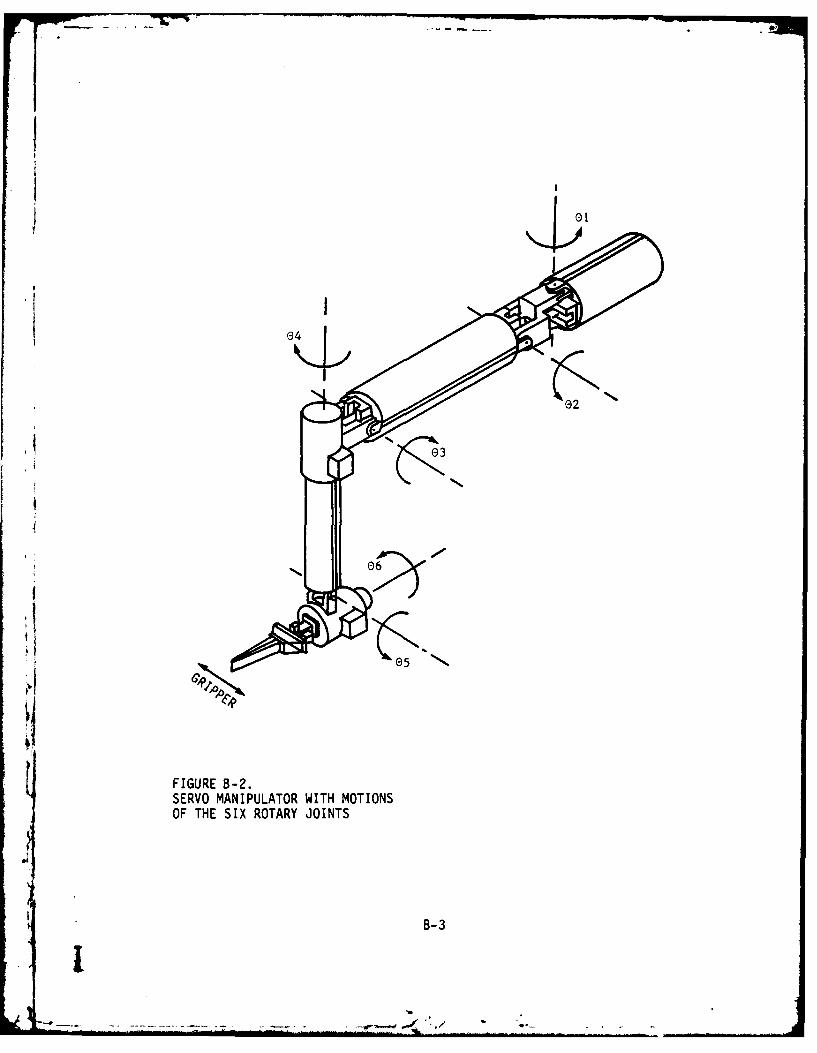
I!
16
FIGURE 8-2.SERVO MANIPULATOR WITH MOTIONSOF THE SIX ROTARY JOINTS
B-3
I
-. - - . /

k
These motions provide the six degrees of freedom necessary to position and
orient an object in the work space. With the computer in direct control
of the manipulator, computer programs can provide a direct manual control
mode as well as control modes ranging from computer-assisted functions
(e.g., resolved motion control) to fully automated performance of routine
tasks. In addition, with fully integrated computer software, an operator
can change naturally between control modes to perform a variety of remote
manipulation tasks.
3. Integrated Control Console
3.1 Control Modes
A library of manipulator control routines is integrated into a single
computer program, which permits the operator to select any of several
control routines in any desired sequence. The available mode options in-
clude:
(1) Direct Control. This mode gives the operator direct manual
control of each manipulator joint angle. Each degree-of- Ifreedom of the joystick controllers is associated with a
specific manipulator joint. r(2) Resolved Motion Control (RMC). This control mode allows the
operator to move the wrist along task or world coordinates.
Each degree-of-freedom of the joystick is associated with pmovement of the manipulator end-effector along a specific
X, Y, or Z axis of the work space. The operator specifies
the speed and direction of motion of the manipulator wrist, Iand the computer calculates the required angle of each joint
and outputs these as commands to the individual joints of I
s3-4
-!

the manipulator. RMC frees the operator from the responsi-
* I bility of determining which combination of speed and motionswill produce the required trajectory.
(3) Automatic Commnands. Under Automatic Motion Control (AMC),the computer assumes control and moves the amn from itscurrent location to any preassigned location. Under FixedCommands, the computer performs single unitary motionsthrough the operator's keyboard comands. Under Variablecommnand, the computer records and moves the arm automatically
* to previous recorded configurations (extended AM4C); acceptstask procedure and supervises automatic execution of complextasks, with possible intervention and modification by theoperator. Under Chained conmmand,* the computer decodes taskprocedures and performs the functions under the VariableComm~and mode.
(4) Speed Adjustment. This option allows the operator to selectthe maximum rate of manipulator motion. The joysticks arerate controllers with greater stick deflection, providingfaster manipulator movement. The speed adjustment routineallows the operator to select one of the three rates overwhich the joysticks function.
(5) Other System Features,. This includes enable/disable of wristinvariance function, enable/disable of force sensor messages,enable/disable of 3D display and other commnands: definition,activation, edition, and alphanumeric feedback features, etc.
B-5

3.2 Console Configuration
The man-machine interface consists of a control console by which an oper-ator can manually control arm motions, select computer assistance control
functions, and observe control status.
The operator uses both joysticks and the pushbuttons to control the man-
ipulator. The joysticks are used for manual control, and the pushbuttons
are used for control mode selection. Using the pushbuttons and joysticks,
the operator can smoothly take the manipulator through a sequence oftasks, selecting control modes, rates, and manual operations that aremost appropriate for each subtask. For example, he may use Automatic
Commnand for gross movement from the stowed position to the target area.He can then change immnediately to RMC for fine movements and for alignment
and insertion. While in the RMC mode, the operator can move the arm toJthe "drop" point, and then record the latter point to facilitate repetition
of the task. IOne alphanumeric CRT display and two TV monitors are used to provide system
state feedback and two-view TV viewing of the manipulator work space. Thedetails were discussed in Chapter 4. Also included in the display cap-
abilities is a computer-generated three-dimensional, stick-figure displayj
of the work environment, which is described in the next section.
3.3 3-Dimensional Display
Figure B-3 is a photograph of the Perceptronics 3-D display. The three- Idimensional image is created by a patented mirror mechanism positioned in
front of a fast Cathode Ray Tube (CRT). The mirrors vibrate forward and Iback to produce a volumetric image in the viewing area. The viewer looksdirectly at the CRT screen. This means that the image can be as detailed 1
B-6

,62%,'
FIGURE B-3.3-D DISPLAY TERMINAL
B-7
and as bright as the CRT itself, although actual resolution is determinedby digital memory size and data throughput rates. As presently configured,
the image space is about 3i* inches deep. The image can be viewed without
special glasses or optics, and can be photographed by single-lens or
stereo camieras. Parallax is present, so that by changing viewing position,
the user can look around the image for a better view of any side.
In the computer, the image is made up of a stack of two-dimensional X-Y
planes, where X and Y correspond to the dimensions of the CRT screen.
Each plane represents the information at a given depth in the Z direction,
and is termed a Z-plane. Z-planes are stored in digital memory, and are
output sequentially in synchrony with the movement of the mirror unit.
Synchronizing signals are provided by a photocell detector. Generation of
a complete image requires output of all Z-planes. By outputting the
complete stack of planes at 30 cps, a rate above the critical flicker rate
of the human eye, a continuous three-dimensional image is achieved. The
image is inherently transparent, allowing views into solids and through
plane surfaces.
During operation with the manipulator, the computer calculates the imageI
coordinates of the arm and generates a "stick figure" image of the arm on
the 3-D display. As the arm moves within the work space, the displayed
arm figure moves in a corresponding manner within the 3-D image volume.
Present configuration of the 3-0 display used in the experimental study
does not allow direct user interaction with the actual image space (such
as on-line measurement and rotation, etc.) and no real-time capabilities
of environmental mapping are provided. What remains as an untested opera-
tion, therefore, is the force sensor attached to the manipulator wrist,
in which an image of objects in the work space can be created by recording
and displaying those points in space where the end-effector touched the
object. Once the outlines of the object have been established by contact
B- 8

mapping, the operator can position the manipulator in the image space to
bring the end effector into contact with the work object, and can initiate
automatic control routines, thus allowing task performance in visually
degraded environments.
4. Computer Control System
4.1 Control Processor
The supporting processor for the manipulator system is an Interdata Model
70 minicomputer. This machine has a memory cycle time of 1 us and basic
instruction execution times averaging between 1 and 3 ws. As presently
configured, the processor system includes 48 kilo bytes of core memory,
a high speed paper tape reader/punch, a line printer, a CRT alphanumeric
terminal, a selector channel, a disc memory and a re-settable precision
interval clock. The disc drive, CRT, and other peripherals are used to
support program development work and are not part of the real time mani-
pulator control system.
4.2 Processor Interface
Data transfer between the computer and manipulator servo-electronics and
between the computer and the control console is performed by a Perceptronics
+1/0 Progranmnable Interface. Besides providing all analog-to-digital
(A/D), digital-to-analog (D/A), and digital-to-digital (D/D) conversions
among the system components, this interface allows the outputs of all
controlled devices to be treated by the processor as if they were the
product of only one device, thus simplifying the software arrangements at
the processor.
The +1/0 Interface contains a number of functional modules arranged along
a transfer buss by which commands, data and status signals are communicated.
B-9

These modules perform such individual functions as standardizing coimuni-
cation with the processor, sequencing data transfers across the buss, and
performing D/A conversion and output.
In addition to an interface module between the processor and interface,
the +1/0 includes an AID module that is used to interface with the servo
position potentiometers and control console joysticks. Thirty-two indivi-
dually addressable input channels are provided. An eight-channel D/A
module is used for converting and sending position commiands (voltages) to
the control inputs of the servos. Finally, a D/D module is used to pro-
vide the 16 input and output channels for the button and lamp arrays of
the control console.
4.3 Software
The software system includes three main modules shown in Figure B-4.
Module 1 is the main control process. It contains the central loop which
executes most of the software functions. All the programs of primitive
and non-primitive functions, joystick control and state commu~and programs
are included in this module. Module 2 is the teletype process module.
It contains the programs which read the keyboard codes, then analyzes and
interprets them. Module 3 is the I/0 process module. It contains programs
which "read" and "write" and send characters to the CRT.
The following sections summnarize the status and functional structure ofeach module. More detailed documentation can be found in earlier reports(Crooks, Shaket, Alperovitch, 1978; and Crooks, Shaket, Chu and Alper-
ovitch, 1979).
*1 B-10

,COYS R.
READON -HR 7" .ARo
~~~~TY 'IO ODULE
B.ufferg.
~RFRCD QMAR
DATANAYZ CONETINDODLE
OFCOO Epte
Cosl
BufferI'BDC REGZC-GNCA
RC CHAE
GEERT

4.3.1 Main Control Process Functional Structure.
MNIP78 - Including the miain control process function as shown in
Figure B-5. This is the highest level program of the system. It invokes
a sequence of routines which are initialized in the system. It then
senses the switches of the computer's panel; and if all of them are reset,
then a system calibrating program is invoked followed by termination. If
at least one of the switches is set, the EXPER program is invoked and an
experimental session can be conducted. When the experiment is concluded,
a sunmmary program is invoked and the data which was monitored during the
session is processed and printed as a report.
EXPER - This is the central program of the system by which most
of the other programs are invoked. Basically, the program is a one "DO
WHILE" loop executed every 100 ins. The while condition is the same as in
MNIP78. Whenever all the switches are reset the program terminates; other- Iwise it loops on. The main cycle is a long sequence of programs which is
invoked in certain contingencies. Generally, each program has a flag which
indicates whether it should be invoked or not. A short description for
each program is given below.
INITAB - Initializes screen and core where points, chains and7
paths are stored.
READSP - Sets the feedback display format according to the selected
mode of machine state feedback. -
MONITOR CURRENT PRIMITIVE - Includes several automatic comm~and
monitoring programs. When a primitive commnand code is in the executionarea, it invokes the PRIMMI, which monitors primitives execution. Ifprimitive execution is finished, INTRP is invoked and it fetches a new
primitive into the execution area.
B- 12

INICR! EAS
FIGURE B-5.MAIN ~ ~ ir MODULE HIRRCIALTERSRUTR
INITTB-i 3
Ijmo YU---- M-,*..-

1iiQMAL- Manages the queues of commands for execution.
COPYQ - Copies the invisible queue into the visible queue.
ROTATE - Performs end gripper rotation.
GRIP - Closes and opens the gripper.
FORBKW - Moves the gripper forward or backward preserving constant
orientation.
GOTO - Performs goto point. A special feature is added to the
"goto" function. Whenever "goto point" executes and the operator manipu-lates the joysticks in the same time, in order to change the final manipu-
lator's position, the final goal point is adjusted accordingly, and the 1function terminates when manipulator reaches the adjusted goal point.
EXCTRA - Executes trajectory forward and backward.
MANUAL - Stops primitives execution to enable manual intervention Iwith joysticks.
EXCRED - Is invoked to monitor commands which are submitted toexecution. It is a part of the real-time monitoring system.
COPY - Copies input floating values into output floating values.p
INTTRN & UDATTR & CARTSN - Transformation routines which aretransforming values in link space into cartesian space.
SNSCVV - Sensors conversion routine. It processes the raw input
4 data coming from the sensor and checks for threshold excess values.
B-14 ."

CRITER - Sensors (stress and torque) criteria routine which pro-
tects the manipulator from damage by generating indication of warning and
stop conditions.
TDMON - 3-D monitoring routine.
DEFPNT - Define point routine.
DEFTRA - Define trajectory routine. It is invoked whenever the
trajectory flag is on and specific synchronization conditions are prevail-
ing.
TDACC - Three dimensional display activation routine. It should
be only invoked when the 3-D is hooked up. All the following programs are
invoked only by the main cycle.
SCALE - Scales input integer values which are read from the +1/0
into radius floating values.
JSTRCD - Is the second real-time monitoring program, which monitors
joystick activity whenever it is operated.
Now, continuing down the main cycle loop, we see:
DIRECT - Joysticks direct control program which changes manipulator
links according to values received from joysticks.
RMC - Joysticks resolved motion control program which enables
manipulation in cartesian space.4I INVAR - Grippers constant orientation preserving routine.
B-151 ,

UNSCALE - Current floating point values are unscaled into integer
values which are written into the I/O.
SSW- Sense switches routine.
FEEDM - CRT feedback display generating routine, including routinesto display command inputs, commands in queue, sensor and system status.
NEWDO - Displays on screen a visible queue.
DSCHDQ - Displays on screen a chain in execution.
INPTDQ - Increments pointer of displayed chain.
ERASDQ - Erases from screen displayed queue.
INPTCH - Increments pointer of displayed chain.
ERCHDQ - Erases displayed chain from screen.
SNSWRN - Displays sensor warning message.
SNSTOP - Displays sensor stop message.
4.3.2 TTY Process Functional Structure
TYINI Handles the codes received from the keyboard. 1ANLIZR - Performs monitoring of syntactical errors and cancelations.
KBDRCD - Automatically monitors every command which is entered Hon the keyboard.
B- 16

PRFRCD - Performs actual monitoring of command into core prefixed
by value of the clock at time of invocation.
RECGNZ - Recognizes valid sequences of codes using finite state
recognizer.
CHAGEN - Generates chain under the edit mode.
CODGEN - Generates codes and sets flags when valid commands arerecognized.
4.3.3 I/O Process Functional Structure
I/ODVR - It is the Main program of the I/O process.
READ - Read manipulators link values into core.
COMPAR - Emergency compare provided to stop the arm whenever the
difference between the input and output values exceed a certain threshold.
WRITE -Writes new values into the manipulator.
TTYOUT - Outputs characters to CRT from high and low priority
buffers.
4.3.4 3-D Display Utility Programs. A set of programs which was used to
perform basic graphics operations on the 3-D display is specified here.
The group of programs is compatible with Fortran V and/or Fortran IVprograms as well as with assembly language programs, such that default
values are supplied in the absence of explicit parameters, where possible.
The basic operations available are the displaying of single points andB
B- 17
* i -

771
arbitrary lines (represented as a series of points) in a three dimensional
graphics work space. Supporting the above will be a small number of
utility functions.
A number of contiguous memory locations may be allocated as the display
buffer. The buffer is considered to be partitioned into smaller con-
tiguous areas, each of which correspond to one Z-frame or cross-section
of the display space.
Although each program is accessible from Fortran, all coding is in Inter-
data 70 assembler language to provide byte and bit manipulation,
special I/O capability, and for ease of internal commnunication between
programs in the package.
Initialize Display - D3INITj
This routine is called to initialize a buffer. It sets all entries to
zero, sets the mode for that buffer and if variable mode, sets the inten-
sity for that buffer.I
Starting Display - D3TURN
This utility routine is used to start or stop the display. It should not
be used until a display buffer has been created.I
Obtaining 3-0 Status - D3STAT
This routine is provided to enable the user to obtain two binary inputs
available from the 3-0 through a sense-status commnand, and to tell whether
or not the selector channel is busy outputting to the display. The actual
B- 18 I

D3TURN. Thus, D3STAT cannot be called until D3TURN has previously been
called. After D3TURN has been called, however, the binary inputs are
available to the user through D3STAT (i.e., on an asynchronous basis with
respect to the operation of the 3-D and selector channel). The information
as to whether or not the selector channel is busy allows the user to
utilize the "backswing" of the 3-D mirror for buffer modifications if
desired.
Defining Points - D3PONT
This routine inserts points into the display buffer specified by the
"D3BUFF" routine. It does not cause those points to be displayed unless
the specified buffer also happens to have been selected by the "D3TURN"
routine.
Deleting Points - D3DELP
This allows one to delete points created by "D3PONT."
Defining Lines - D3LINE
This utility creates lines in the display space consisting of several
points.
I Delete Lines - D3DELL
As with D3OELP, this routine removes lines previously created with D3LINE.
In fact, it is used essentially the same as D3DELP.
Point Imaging Routine - PPOINT
This routine allows the user to specify a location in the manipulator work
4space in floating Cartesian coordinates within the range of that work space
B-19
ii1

(i.e., -36.0 < x < 36.0, 0.0 < y :i 36.0, -32.0, < z <32.0). A point
image is placed in the corresponding location in the 3-D work space
through a call to D3PONT.
Manipulator-Arm Imaging Routine - ARM
On the first call to this routine, the new arm image is placed in the
buffer with D3LINE. Thereafter, D3DELL is first used to delete the old
arm image before the new image is constructed.
4.3.5 Real-Time System Constraints. Average execution of the main
control functions (excluding 3-D interface) takes about 60 ms; and theloop is executed every 100 ins. As the technique of intermediate coord-
inate frames is used, spatial transformation calculations required approx-imately 30 milliseconds of computer time as compared with approximately500 milliseconds for direct transformations. The Perceptronlcs computer
system is programed to output updated arm angle colmands at 100 milli-second intervals. During the 100 millisecond interval, the computerreads the current arm position, joystick controller positions, and command
pushbutton status, as well as calculates spatial transformations andIperforms overhead functions. With this 100 millisecond coummand interval,
the manipulator end-effector can be moved under RMC mode in excess of 20
inches per second with no noticeable jerkiness and no overshoot.
The clock interrupts are generated every 4 ms and CPU control is trans-ferred to TRAPI until execution of the 1/0 module is finished and controlTis returned to the main module. Execution of an 1/0 interrupt takes about
1 ins. The 1/0 module is regarded as a critical section, so that any other-
interrupts are disabled.
8-20

With the use of 3-D graphics, the space-time trade-offs of the system
resources become crucial. The rule-of-thmb for synchronizing 3-D inter-
face is that each 3-D Z-frame is equal in length to the length of the
display buffer minus 8 divided by 256. With the selector channel to the
3-D operating at the rate of one output per 5 microseconds, and the 3-0
display operating at the rate of one mirror cycle every 33 milliseconds,
the optimum buffer size would be about 6152 bytes in constant mode and
9224 bytes in variable-intensity mode (multiples of 256*2 bytes + 8,
utilizing 15.36 milliseconds of the 16.15 milliseconds available on one
forward sweep of the 3-D mirror). Each Z-frame would then last long enough
for 12 points to be output.
The TTY module is invoked by the keyboard generated interrupts. Control
is transferred to TRAP2 and the TTY module is executed while any other
interrupts are disabled. An average execution time takes about 1 ms. In
order to respond to coming interrupts with minimal delay, the main process
must not disable CPU interrupts for long periods of time. This requires
an even distribution of critical sections along the main process control
flow so that an I/O or TTY nterrupt will not get lost.
We can visualize the concurrent processes in the system in the following
way. There is a basic cycle every 100 ms. For about 60 ms, the CPUworks on the main control loop. Clock interrupts are coming every 4 ms.,
so that control is diverted to the I/O process. One TTY interrupt can
occur during the cycle, and its time consumption is negligible. Overallin about 10-15 ms. of 100 ms. cycle, the CPU is free for other appli-
j( cations, such as interactive graphics or sensor processing.
B-21
-- --- ----- --- -IS -
5. Operational Procedures
5.1 Starting Sequence
At the Manipulator's Site:
(1) Turn on the hydraulic pump.
* (2) Open the hydraulic valve on the manipulator.
(3) Turn on the video cameras.
At the Experimenting Site:
(1) Turn on the button for power, hydraulic and computer on the
upper right hand side of the operator's keyboard.
(2) Turn on the two video displays.
(3) Turn on the feedback control display.
At the Computer Site:I
(1) Turn on the +1/0.1(2) Turn on the main disc switch (colored red).
(3) Open the disc's case and put in the ONR79 + 3D disc.T(4) Make sure that both "write protect" are ON.
(5) Close the disc's case and press the RUN/STOP button.(6) Turn on the ADDS terminal.
(7) Wait until the READY button is lit before proceeding with
the rest of the sequence.
(8) Bring up the disc operating system, DOS, by the following
sequence:
(a) Set rotary switch to ADR/MRD.(b) Set panel switches to HX '02D0'
8-22

(c) Reset RUN and SGL switches and press EXC switch.
(d) Set rotary switch to PSW.
(e) Press INIT, RUN and EXEC switches.
(f) If DOS doesn't show on screen--repeat Step a through
e--if it still doesn't work--get help.
(9) Activate the system load module file by typing: AC ONR79, IC7.
(10) Load and start by typing: LO 1
ST 2C00
(11) Turn on power switch on 3-D.
(12) Turn off the disc drive by pressing the ON/OFF switch.
(13) Start experimentation.
5.2 Stopping Sequence
At the Computer:
(1) Reset all panel switches--so that the system stops.
(2) Make sure the disks are not running or else turn them off
and wait for the SAFE light before proceeding on.
(3) Turn off the disc's case using the big red switch.(4) Turn off computer, terminal and +1/0.
At the Manipulator Site:
(1) Turn off hydraulic valve and pump.(2) Turn off the video cameras.
B-23

At the Experimenting Site
(1) Turn off the operator's keyboard.
(2) Turn off 3-0, video displays, and control display.
5.3 Report Generation Operating Sequence
This sequence should be executed immediately after experimental session
sequence.
Starting Sequence
(1) Reset all panel switches so that system stops.
(2) Perform the usual stopping sequence at the manipulator and
experimenting sites as shown in 5.2.
(3) Open the disc's case and put MOSHE disc -instead of the
ONR79 + 3D.
(4) Remove the "write protect" from the upper disc.
(5) Turn-on the disc driver.
(6) Turn-on the line printer.
(7) Wait until the READY button is lit and then proceed.
(8) Activate the system control file by typing AC RUNMCJN, 5C7.(9) Transfer control to it by typing: TR 5.
(10) When report printer terminates perform the stopping sequence.
Stopping Sequence
(1) Turn off the discs by pressing the ON/OFF button.(2) Turn off the computer, terminal and line printer.
(3) Wait until the SAFE light is on.
(4) Turn off the main disc switch.
B- 24

APPENDIX C
LIST OF REPORTS AND PUBLICATIONS
S.
a.
I-

Reports
Berson, B.L., Crooks, W.H., Shaket, E., and Weltman, G. Man-MachineCommunication in Computer-Aided Manipulation. Perceptronics, Inc. (Wood-land Hills, CA) Technical Report PATR-1034-77-3/1, March 1977.
Crooks, W.H., Shaket, E., and Alperovitch, Y. Man-Machine Communication inComputer-Aided Remote Manipulation. Perceptronics, Inc. (Woodland Hills,CA) Technical Report PATR-1034-78/3, March 1978.
Alperovitch, Y. ONR 77 Software Documentation. Perceptronics, Inc. (Wood-land Hills, CA) Software Documentation PSD-1034-78-3/1, March 1978.
Crooks, W.H., Shaket, E., Chu, Y. and Alperovitch, Y. Man-MachineCommunication in Computer-Aided Remote Manipulation. Perceptronics, Inc.(Woodland Hills, CA) Technical Report PATR-1034-79/3, March 1979.
Chu, Y., Crooks, W.H., and Shaket, E. Man-Machine Communication in Com-puter-Aided Remote Manipulation. Perceptronics, Inc. (Woodland Hills, CA)Technical Report PATR-1034-80/3, March 1980.
Conference Papers
Shaket, E. and Freedy, A. A Model of Man/Machine Communication in ComputerAided Manipulation. IEEE Conference on Cybernetics and Society, Washington,DC, September 19-21, 1977.
Freedy, A. and Shaket, E. A Model, Language Design and Experiments for Man/Machine Communication in Computer Aided Manipulation. Third CISM IFToMMSymposium on Theory and Practice of Robots and Manipulators, Udine, Italy,September 12-15, 1978.
Shaket, E., Freedy, A., and Crooks, W.H. Evaluation of a Command Languagefor Supervisory Control in Computer Aided Manipulation. InternationalConference on Cybernetics and Society 1978, Tokyo, Japan, November 3-5,1978 and Kyoto, Japan, November 7, 1978.
Chu, Y. and Crooks, W.H. Man-machine Communication in Computer AidedTeleoperator Control Systems. 24th Annual Meeting of the Human FactorsSociety, Los Angeles, CA, October 1980.
C-1

DISTRIBUIION LIST
CDR Paul R. Chatelier Dr. Robert G. Smith
Office of the Deputy Under Secretary Office of the Chief of Navalof Defense Operations, OP987H
OUSDRE (E&LS) Personnel Logistics PlansPentagon, Room 3D129 Washington, D.C. 20350Washington, D.C. 20301
CDR G. WorthingtonDirector Office of the Chief of NavalEngineering Psychology Programs Operations, OP-372GCode 455 Washington, D.C. 20350Office of Naval Research800 North Quincy Street Dr. W. MehuronArlington, VA 22217 (5 iys) Office of the Chief of Naval
Operations, OP 987Director Washington, D.C. 20350Undersea TechnologyCode 220 Dr. Andreas B. RechnitzerOffice of Naval Research Office of the Chief of Naval800 North Quincy Street Operations, OP 952FArlington, VA 22217 Naval Oceanography Division
Washington, D.C. 20350DirectorInformation Systems Program Dr. Jerry C. LambCode 437 Submarine Sonar DepartmentOffice of Naval Research Code 325800 North Quincy Street Naval Underwater Systems CenterArlington, VA 22217 New London, CT 06320
Special Assistant for Marine Human Factors DepartmentCorps Matters Code N215
Code 1OOM Naval Training Equipment CenterOffice of Naval Research Orlando, FL 32813800 North Quincy StreetArlington, VA 22217 Mr. Mulon Essoglou
Naval Facilities Engineering CommandCommanding Officer R&D Plans and ProgramsONR Western Regional Office Code 03TATTN: Mr. R. Lawson Hoffman Building II1030 East Green Street Alexandria, VA 22332Pasadena, CA 91106
CDR Robert BiersnerCommanding Officer Naval Medical R&D CommandONR Western Regional Office Code 44ATTN: Dr. E. Gloye Naval Medical Center1030 East Green Street Bethesda, MD 20014Pasadena, CA 91106
4Dr. Arthur BachrachDirector Behavioral Sciences DepartmentNaval Research Laboratory Naval Medical Research Institute
j Technical Information Division Bethesda, MD 20014Code 2627Washington, D.C. 20375 (6 cys) CDR Thomas Berghage
Naval Health Research Center
, San Diego, CA 92152
V. "- '

Dr. George Moeller Mr. Arnold RubinsteinHuman Factors Engineering Branch Naval Material Command
Submarine Medical Research Lab NAVMAT 08D22
Naval Submarine Base Washington, D.C. 20360
Groton, CT 06340Mr. Phillip Andrews
Dr. James McGrath, Code 311 Naval Sea Systems Command
Navy Personnel Research and NAVSEA 0341
Development Center Washington, D.C. 20362
San Diego, CA 92152Mr. John Quirk
Mr. J. Williams Naval Coastal Systems Laboratory
Department of Environmental Code 712
Sciences Panama City, FL 32401
U.S. Naval AcademyAnnapolis, MD 21402 Mr. Merlin Malehorn
Office of the Chief of Naval
Dr. Gary Poock Operations (OP-115)
Operations Research Department Washington, D.C. 20350Naval Postgraduate SchoolMonterey, CA 93940 Director, Organizations and
Systems Research Laboratory
Mr. H. Talkington U.S. Army Research InstituteOcean Engineering Department 5001 Eisenhower Avenue
Naval Ocean Systems Center Alexandria, VA 22333
San Diego, CA 92152 IMr. Paul Heckman U.S. Army Human Engineering LabsNaval Ocean Systems Center Aberdeen Proving Ground, MD 21005
San Diego, CA 92152U.S. Air Force Office of Scientific
Mr. Warren Lewis Research
Human Engineering Branch Life Sciences Directorate, NLCode 8231 Bolling Air Force Base
Naval Ocean Systems Center Washington, D.C. 20332San Diego, CA 92152
Dr. Donald A. Topmiller
Dr. Ross L. Pepper Chief, Systems Engineering BranchNaval Ocean Systems Center Human Engineering Division
Hawaii Laboratory USAF AMRL/HESb P.O. Box 997 Wright-Patterson AFB, OH 45433
Kailua, HI 96734 rsDefense Technical Information Center
Dr. A. L. Slafkosky Cameron Station, Bldg. 5
Scientific Advisor Alexandria, VA 22314 (12 cys)Commandant of the Marine CorpsCode RD-1 Dr. M. MontemerloWashington, D.C. 20380 Human Factors & Simulation
Technology, RTE-6NASA HQSWashington, D.C. 20546
2
S~. .7 _=7

Dr. T. B. SheridanDepartment of Mechanical EngineeringMassachusetts Institute of Technology
Cambridge, MA 02139
Dr. Harry SnyderDepartment of Industrial EngineeringVirginia Polytechnic Institute and
State UniversityBlacksburg, VA 24061
Dr. W. S. VaughanOceanautics, Inc.422 6th StreetAnnapolis, MD 21403
Dr. Robert WilligesHuman Factors LaboratoryVirginia Polytechnical Institute
and State University130 Whittemore HallBlacksburg, VA 24061
Dr. Alphonse ChapanisDepartment of PsychologyThe Johns Hopkins UniversityCharles and 34th StreetsBaltimore, MD 21218
Journal Supplement Abstract ServiceAmerican Psychological Association1200 17th Street, N.W.Washington, D.C. 20036 (3 cys)
* Dr. Christopher WickensUniversity of IllinoisDepartment of Psychology
Urbana, IL 61801
I
.... a . ... .

Mr. Glenn SpaldingNaval Material Command,
MAT 07Washington, DC 20360
Mr. Jim KatayamaNaval Ocean Systems CenterHawaii LaboratoryP. 0. Box 997Kailua, Hawaii 96734
Dr. John K. DixonComputer ScientistNaval Research LaboratoryWashington, DC 20375
MAJ Jack Thorpe LCybernetics Technology OfficeAdvanced Research Projects Agency1400 Wilson Blvd.Arlington, VA 22209
Dr. A. K. BejczyJet Propulsion LaboratoryCalifornia Institute of TechnologyPasadena, CA 91103
Dr. John LymanBiotechnology LaboratorySchool of Engineering and Applied SciencesUniversity of CaliforniaLos Angeles, CA
Mr. Clifford Winget[Woods Hole Oceanographic Institute
Woods Hole, MD 02543
Dr. William VerplankXerox Business SystemsSystems Development Department701 S. Aviation Blvd.El Segundo, CA 90245 [
4
7'-7-1

T7 UNCLASSIFIEDSECURITY CLASSIFICATION OF THIS5 PAGE (When DeatEnlered)
.VREPORT DOCUMENTATION PAGE READ INSTRUCTIONS
I. REPORT NUM661ER12 GOVT ACCESSION No: 3. VNTS CATALOG NUMBER
4. ITE (ldaabite)Final chnlcal e t *
Man-Machine Communicaoni Remote Manipulation: 2Fe 7-W1eb8'
-FT-1a~A ea AfTNHUMMER
AUTH Ra ft
A0 00 VO AN T NUMBER(&)Yee-Yeen/Chu (j5 N1 76CgWilliam H. /Crooks 00
ORAIZATION4 MAMIE AND ADDRESS 10. PROGRAM ELEMENT. PROJECT. TASK
Perceptronics, Inc.v AREA & WORK UNIT NUM§ERS
6271 Variel Avenue NR 196-140Woodland Hills. CA 91367 _____________
11. CONTROLLING OFFICE NAME AND ADDRESS 12. Re X~
Office of Naval Research (Code 455) / a~800 N. Quincy Street 6L 4 MEr1I
4E
Arlin aton, VA__22217 23214. MONITORING AGENCY NAME & ADORESif different from, Controins Office) IS. SECURITY CLASS. (of this repert)
UnclassifiedIS. OECL ASSI FI CATI ON/ DOWN GRAOI NO
Ij -1 SCHEDULE
III. DISTRIBUTION STATEMENT (of this Report)
Unclassified - Distribution of this document is unlimited
17. DISTRIBUTION STATEMENT (of the abotroct entered in Block 20, It different Irom Report)
13. SUPPLEMENTARY NOTES
III. KEY WORDS (Continue on revere eide it necessary and Identity by block nuinber)
Command Language Man-Machine Commnuni cationComputer-Aided Control Remote ManipulatorControl Display Supervisory ControlHierarchical Planning Task-Oriented Supervisory ControlMan-ComDuter Interface Design Teleoperators
20. ASTRACT (Continue an revers* side if necoeemy and identify by block rnamnber)
Computer-aided control of a general purpose teleoperator system provides aprime example of a new type of man-machine interaction in which the humanoperator must supervise and control a complex and often adaptive computerizedsystem. Earlier studies showed that the communication between the operatorand the computer-controlled system is an important determinant of the overallsyte anderformace. This report represents the results of a set of analytical
and xpeimetalstudies focusing on the effectiveness of conmmand and feedback
1A:N7s 1473 £01 ToN OF 'NO 85 s Is O~T Uncl assi fiede/.v'.. sSECURITY CLASSIFICATION OF TNI1S PAGE (fte. Onto titsq.0

ull n 1 7 1
SECURITY CLASSIFICATION OF THIS PAGE(th4i Doe Enmated)
20. ABSTRACT (CONTINUED)
modes for improved man-machine communication in supervisory control loop,where the operator may plan the tasks, command goal-directed actions, monitortask performance, and control when appropriate. The experimental resultsindicated that high-level command structure of computer-aiding functionscan significantly improve task performance, especially in degraded environ-ment. The study also suggested that feedback display of task status in-volving both machine state and environmental interaction is essential forsuccessful manipulation.
This report describes (1) general teleoperator task functions, especiallythose required in underwater manipulation, (2) the theoretical analysis ofman-machine communication based on the procedural nets model, and thedevelopment of the task-oriented supervisory command (TOSC) language, (3)a series of experimental investigations on the effect of command languagefeatures and feedback display on the ability of trained operators to performselected remote manipulation tasks, (4) methods to evaluate overall tele-operator performance and a model for predicting performance as a functionof command mode, intrinsic task characteristics, and environmental feedback,(5) a man-machine communication design methodology and guidelines forapplications.
T
':1
I Iit
IIUnclassified
SECURITY CLASSIFICATIOU O 1--- PAGZ(Wh. Data Enteed)
-- ",. -. .