3D Simulation for Rubber Injection Moulding - A New Tool ... · PDF file3D Simulation for...
12
3D Simulation for Rubber Injection Moulding - A New Tool for Process Optimisation Lothar H. Kallien Sigma Engineering GmbH, Germany 1 INTRODUCTION During the development of injection moulded rubber components simulation tools are used to predict die filling, curing and the subsequent cooling of the rubber material /1,2/ . Conventional programs use geometry representations, which describe the midplane surface of the real part. These simulation codes are usually referred to as '2½D'. This technique was developed for parts with a high surface area to volume ratio. For bulky parts this geometric description can have a negative influence on the quality of the results /3,4/ . In addition, three-dimensional effects such as jetting can not be calculated as these programs presume parallel flow across the wall thickness. Figure 1 shows areas in a part where three dimensional flow phenomena play a significant role. In the past 5-10 years 3D CAD systems have become widely available. However, 2½D programs can not take advantage of these models. The effort required to generate 2½D models from on 3D models is sometimes equivalent to generating 3D information from scratch /5,6/ . These fundamental reasons have motivated the development of 3D simulation programs for the injection moulding of rubber and plastic parts /5,6/ . Figure 1 Areas in a part where 3D flow phenomena exist which can not be described by 2½ D programs 2 3D SIMULATION OF THE FILLING PROCESSES 2.1 Simulation of Casting Processes For the simulation of casting process, 3D simulation codes have been in use for more than a decade /7/ . Most cast components such as cylinder heads and engine blocks are 3D geometries, which can not be described by 2½D midplane models, see Figure 2. Figure 2 The images show a cast cylinder head and the simulated temperature distribution during solidification using MAGMASOFT®. MAGMA Gießereitechnologie GmbH of Germany, which develops and distributes the MAGMASOFTâ program, has played a leading role in the development of casting simulation. With MAGMASOFT® the filling, cooling, solidification and distortion of metal castings can be analysed and optimised. Within the last years new modules have been developed to predict the flow of non-Newtonian fluids /8/ . With these solvers it is also possible to simulate the shear thinning flow behaviour exhibited by rubbers and plastics. 2.2 2½D and 3D in Comparison Figure 3 shows a direct comparison between 2½D and 3D simulation techniques. Thermal effects at rib junctions, which lead to sink marks, are neglected in 2½D. To compare 2½D and 3D technology the IKV (Institute for Plastic Processing) of Aachen analysed the flow in critical test geometries using high speed monitoring. Figure 4 shows the fill time versus the flow front position for a 3D and 2½D simulation in direct comparison with the experiment. When the plastic is injected into the cavity jetting occurs and the position of the flow front is retarded /3,4/ . This three-dimensional effect is only detected by the 3D simulation code MAGMASOFT . Paper 6, Page 1 Innovations in Rubber
Transcript of 3D Simulation for Rubber Injection Moulding - A New Tool ... · PDF file3D Simulation for...
3D Simulation for Rubber InjectionMoulding - A New Tool for Process
OptimisationLothar H. Kallien
Sigma Engineering GmbH, Germany
1 INTRODUCTION
During the development of injection moulded rubbercomponents simulation tools are used to predict die filling,curing and the subsequent cooling of the rubber material /1,2/.Conventional programs use geometry representations, which describe the midplane surface of the real part. Thesesimulation codes are usually referred to as '2½D'. Thistechnique was developed for parts with a high surface area tovolume ratio. For bulky parts this geometric description canhave a negative influence on the quality of the results /3,4/. Inaddition, three-dimensional effects such as jetting can not becalculated as these programs presume parallel flow across the wall thickness. Figure 1 shows areas in a part where threedimensional flow phenomena play a significant role. In thepast 5-10 years 3D CAD systems have become widelyavailable. However, 2½D programs can not take advantageof these models. The effort required to generate 2½D modelsfrom on 3D models is sometimes equivalent to generating 3D information from scratch /5,6/. These fundamental reasonshave motivated the development of 3D simulation programsfor the injection moulding of rubber and plastic parts /5,6/.
Figure 1Areas in a part where 3D flow phenomena exist which can not
be described by 2½ D programs
2 3D SIMULATION OF THE FILLINGPROCESSES
2.1 Simulation of Casting Processes
For the simulation of casting process, 3D simulation codeshave been in use for more than a decade /7/. Most castcomponents such as cylinder heads and engine blocks are 3D
geometries, which can not be described by 2½D midplanemodels, see Figure 2.
Figure 2The images show a cast cylinder head and the
simulated temperature distribution during solidification usingMAGMASOFT®.
MAGMA Gießereitechnologie GmbH of Germany, whichdevelops and distributes the MAGMASOFTâ program, hasplayed a leading role in the development of castingsimulation. With MAGMASOFT® the filling, cooling,solidification and distortion of metal castings can beanalysed and optimised. Within the last years new moduleshave been developed to predict the flow of non-Newtonianfluids /8/. With these solvers it is also possible to simulate theshear thinning flow behaviour exhibited by rubbers andplastics.
2.2 2½D and 3D in Comparison
Figure 3 shows a direct comparison between 2½D and 3Dsimulation techniques. Thermal effects at rib junctions,which lead to sink marks, are neglected in 2½D.
To compare 2½D and 3D technology the IKV (Institute forPlastic Processing) of Aachen analysed the flow in criticaltest geometries using high speed monitoring. Figure 4 shows the fill time versus the flow front position for a 3D and 2½Dsimulation in direct comparison with the experiment. Whenthe plastic is injected into the cavity jetting occurs and theposition of the flow front is retarded / 3 , 4 /. Thisthree-dimensional effect is only detected by the 3Dsimulation code MAGMASOFT.
Paper 6, Page 1
Innovations in Rubber

Paper 6, Page 2
Innovations in Rubber
Figure 3 a/bTest part 2 ½ D simulation
Figure 3 c/dTest part 3-D simulation
Figure 4Experimental flow front position in direct comparison with 3D and 2½D simulations /3,4/. The jetting effects can only be
analysed by 3D models.

3 SIGMASOFT® - A NEW SIMULATIONTOOL WITH VOLUME ELEMENTS
The advantages of 3D simulation have led to the foundationof SIGMA Engineering GmbH. The goal of SIGMA is todevelop and distribute 3D simulation software for theoptimisation of rubber and plastic injection moulding.SIGMASOFT is based upon MAGMASOFT , which has been used in industrial applications for more than a decade.
3.1 Geometry Input and Meshing
SIGMASOFTâ can import any 3D solid model generated byCAD packages such as Pro/Engineer, Unigraphics,CATIA etc. For the data transfer into the SIGMASOFTpreprocessor STL-files or direct interfaces are used. Inaddition, FEM meshes can be read in. Runners can bemodelled in SIGMASOFT and added to the part geometry.Meshing is completely automatic and takes only seconds.
The mesh includes the part and the tool with all heatingchannels.
3.2 Flow in 3D
To solve fluid flow phenomena SIGMASOFT® uses theNavier-Stokes' equation /9/. Kinetic effects such as jetting aretaken into consideration. Figure 5 shows the fillingbehaviour at the base of a ribbed geometry. The main streamflows past the first rib until back pressure builds up and the rib starts to fill. The same effect happens in the other ribs. Aclose-up shows the velocity profile at the bottom of the rib,which is asymmetric.
4 SIMULATION OF FILLING AND CURINGSTAGES IN RUBBER PARTS
Rubber parts are often characterised by thick walledgeometries. The part shown in Figure 6 has a wall thickness
Paper 6, Page 3
Innovations in Rubber
Figure 53 D flow effects at the base of a rib, note the asymmetric velocity profile
Figure 6A rubber part with wall thickness varying between 1 and 20mm

between 1mm and 20mm. The 3D simulation is the only wayto properly predict fluid flow and thermal phenomena, whichexist in these parts.
For this part different gate positions have been analysed. Theoriginal gate position led to air entrapment in the thick wallsections, see Figures 7 a and b. Figures 7 c and d show theflow using an alternative gate location. In both cases the freesurface movement and the high temperature gradient over the wall thickness can be observed. SIGMASOFT calculatestemperature, velocity, pressure, the Scorch-Index and thecuring rate as a function of time. Inserts are meshed in 3D andin the same manner the die is included in the calculation.Therefore, the cycle time of new parts can be predicted as afunction of mould and insert temperature.
4.1 Validation of the Results
The results have been validated in collaboration with variouscompanies such as Meteor, BTR, Bosch and Phoenix.Figures 8 a and c show a direct comparison betweensimulation and short fills for a sealing component. Figures 9a and b show the same component with the modified gatelocation. For both cases the simulation matches theexperimental results.
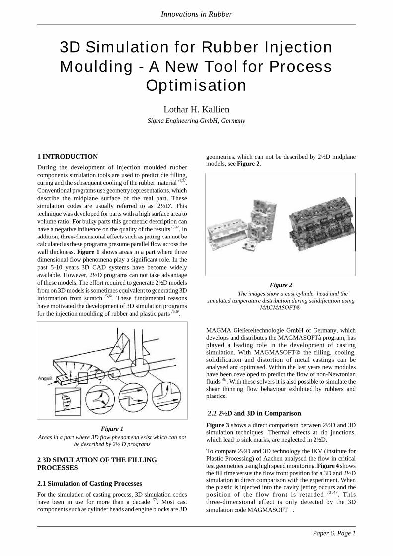
Although, this geometry seams to match the conventional 2½ D approach a closer look at the 3D results confirms thenecessity of a real 3D volume approach. Figure 10 shows aclose-up of the simulation shown in Figure 9. At the position
where the wall thickness changes a jetting effect can be seenwhich may lead to a small amount of gas entrapment.
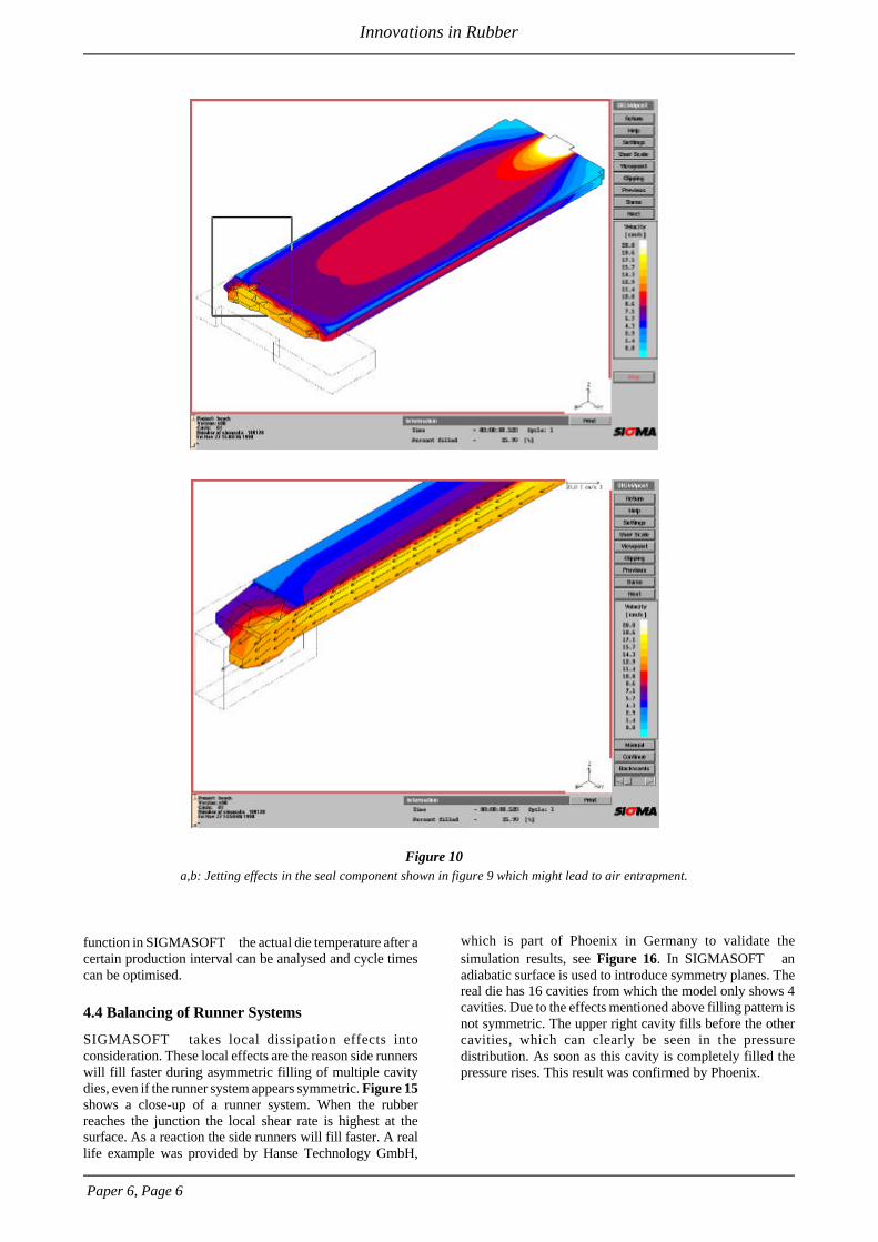
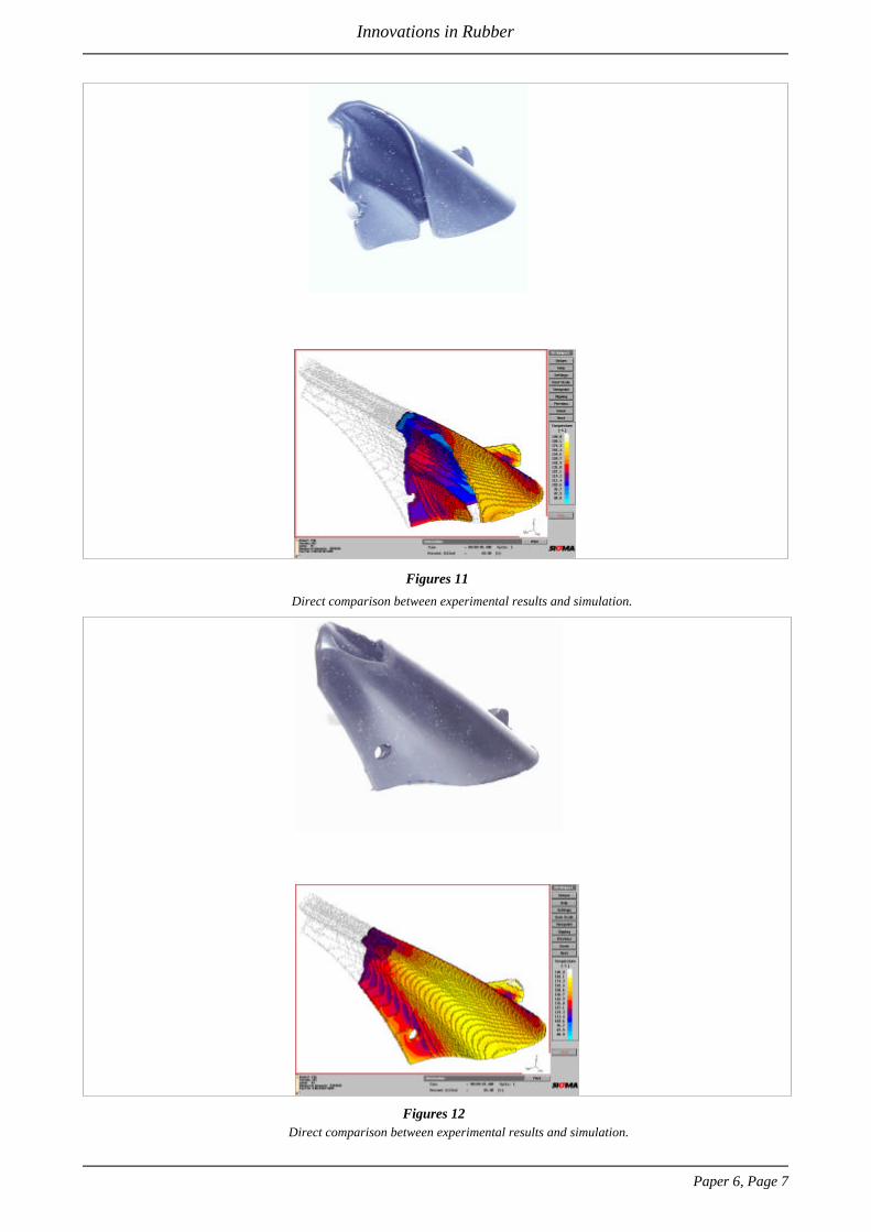
Figure 11 and 12 show a direct comparison betweenexperimental and simulated results for a sealing system. Thefill experiments have been carried out by BTR SealingSystems Group in Germany.
4.2 Parts with Metal Inserts
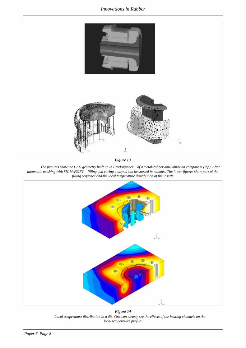
Figure 13 depicts the Pro/Engineer CAD data of ananti-vibration system which includes several inserts. TheCAD information is easily transferred into SIGMASOFTusing the SIGMAPro/E-interface or the Stereo-lithographie-interface. In the SIGMASOFT preprocessorthe various materials involved are asigned the appropriatethermophysical properties. Aluminium inserts have different thermal conductivity compared to steel inserts. Using thecompletely automatic mesh generator the simulation can bestarted within minutes. Figure 13 shows a snap shot of thefilling sequence of the part and the local temperaturedistribution in the inserts.
4.3 Temperature Distribution in the Die
Figure 14 depicts a cross section through a heated die. Thecolours refer to the temperature distribution in the die. Thetemperature distribution is inhomogeneous, parts which arecloser to the heating channels are hottest, which againinfluences the local curing behaviour. Using the multi cycle
Paper 6, Page 4
Innovations in Rubber
Figure 7 a,d:The flow simulation confirms that air is entrapped in the thick walls of geometry, figures 7 a,b. Figures 7 c,d
show an alternative gate location.

Paper 6, Page 5
Innovations in Rubber
Figure 8 a,c:Comparison between simulation and experiments for a rubber seal.
Figures 9 a,b: Comparison between simulation and experiments for a rubber seal.
function in SIGMASOFT the actual die temperature after acertain production interval can be analysed and cycle timescan be optimised.
4.4 Balancing of Runner Systems
SIGMASOFT takes local dissipation effects intoconsideration. These local effects are the reason side runnerswill fill faster during asymmetric filling of multiple cavitydies, even if the runner system appears symmetric. Figure 15shows a close-up of a runner system. When the rubberreaches the junction the local shear rate is highest at thesurface. As a reaction the side runners will fill faster. A reallife example was provided by Hanse Technology GmbH,
which is part of Phoenix in Germany to validate thesimulation results, see Figure 16. In SIGMASOFT anadiabatic surface is used to introduce symmetry planes. Thereal die has 16 cavities from which the model only shows 4cavities. Due to the effects mentioned above filling pattern isnot symmetric. The upper right cavity fills before the othercavities, which can clearly be seen in the pressuredistribution. As soon as this cavity is completely filled thepressure rises. This result was confirmed by Phoenix.
Paper 6, Page 6
Innovations in Rubber
Figure 10 a,b: Jetting effects in the seal component shown in figure 9 which might lead to air entrapment.
Paper 6, Page 7
Innovations in Rubber
Figures 11
Direct comparison between experimental results and simulation.
Figures 12Direct comparison between experimental results and simulation.
Paper 6, Page 8
Innovations in Rubber
Figure 13
The pictures show the CAD geometry built up in Pro/Engineer of a metal-rubber anti-vibration component (top). Afterautomatic meshing with SIGMASOFT filling and curing analysis can be started in minutes. The lower figures show part of the
filling sequence and the local temperature distribution of the inserts
Figure 14Local temperature distribution in a die. One can clearly see the effects of the heating channels on the
local temperature profile.

Paper 6, Page 9
Innovations in Rubber
Figure 15Balancing of runner systems: the rubber is injected into the cavity. Due to wall friction and local shear stresses the
material heats up at the walls. As result, filling is no longer symmetric with the side arms filling first and the middle runner filling atthe end.

4.5 Air Pressure in the Cavity
SIGMASOFTâ allows the calculation of air pressure withinthe cavity based upon the venting conditions defined in thepreprocessor. Figure 17 provides an example of a component which has been filled using the venting option. The X-rayview shows the areas where the air pressure reached amaximum during the filling sequence. These areas are proneto gas entrapment.
5 SUMMARY
The first results of the 3D flow simulation have shown theadvantages of the new 3D simulation technique, whichinclude :
• no additional costs for model generation in thick wallsections;
• 3D flow phenomena (jetting) are calculated in thephysically correct manner
• fully coupled thermal and fluid flow calculation for boththe part and die;
• balancing of runner systems;
• air pressure is calculated as a function of ventingconditions;
• heating channels are modelled in 3D;
• differences in local die temperatures effect the local flowand curing conditions;
Paper 6, Page 10
Innovations in Rubber
Figure 16The upper figure shows the CAD model of 4 cavities, which are part of a 16 cavity die. Due to the local shear effects the
filling is not symmetric for the 4 cavities. The lower figure shows the local pressure distribution shortly before complete filling. Theupper right cavity has completely filled and the pressure rises. The lower right cavity is the second to completely fill. The left hand
cavities fill last . The colour scale ranges from 0 to 2 bar. The actual filling pressure is up to 570 bar. Phoenix in Germany hasexperimentally confirmed the results.

• Scorch-Index and curing rate can be calculated for thickwalled parts;
• inserts are an integral part of the model for which thematerial properties are taken into consideration.
Although 2½D methods have found some applications inindustry, the inherent limitation of the approach as clearlyshown in this paper, will never be overcome without the useof a true 3D model. This approach has, by necessity, beendeveloped and applied industrially over many years in thecasting industry. Based on the experienced gained,SIGMASOFTâ offers the designer and manufacturer theability to evaluate the effects of design changes and processparameters in 3D.
If reality is in 3D, then the answer will only be found in 3D.
6 REFERENCES
/1/ Bogensperger, H.; Durchblick - Erfahrungen mitSpritzgieß-Simula-tionen. Kunststoffe 85 (1995) 1, S. 44 ff.
/2/ Filz, P.F., Genoske, H.; Simulieren statt Probieren.Kunststoffe 88 (1998), S. 954 ff.
/3/ Michaeli, W., Findeisen, H., Gossel, T., Klein, T.; 2,5Dund 3D im Vergleich - Spritzgießsimulation auf demPrüfstand. .Kunststoffe 87 (1997), S. 462 ff.
/4/ Michaeli,W., Zachert, J.; Simulation and Analysis ofThree-Dimensional Polymer Flow in Injection Molding.SPE-AN-TEC, Toronto/Kanada 1997
/5/ Altmann,O., Wirth, H. J.; 3D-CAE-Rheologie über3D-CAD-Volumen-modelle. Kunststoffe 87 (1997) 11,S. 1670 ff.
/6/ van der Lelij, A.; J.3D ist genauer als 2D. Kunststoffe 87(1997) 1, S. 51 ff.
/7/ Kallien, L. H., Smith, R.L.; Optimierung einesDruckgießteiles durch nume-rische Simulation derFormfüllung und der Erstarrung, GießereiErfahrungsaustausch (1994) 7
/8/ Flender, E., Kallien, L., Hepp, E.; H.New developmentsfor process modeling of the thixotropic forming process.Magnesium Konfe-renz der Deutschen Gesellschaft fürMetallkunde, Wolfsburg 1998
/9/ Lipinski D. M., Flender, E.; Numerical simulation offluid flow and heat transfer phenomena for semi-solid processing of complex castings,5th InternationalofAlloys and Composites, Golden, USA, 1998
Paper 6, Page 11
Innovations in Rubber
Figure 17Air pressure maxima in the cavity indicate areas which are prone to air entrapment

Paper 6, Page 12
Innovations in Rubber
Notes