3D Rotational Analysis - Indiana University …sportbm/isb2003-tutorial.pdf3D Rotational Analysis by...
27
3D Rotational Analysis by Jesús Dapena Department of Kinesiology Indiana University Bloomington, IN 47405 USA Notes for a tutorial given at the 19 th Congress of the International Society of Biomechanics, Dunedin, New Zealand, 2003. Tel. 1-812-855-8407 E-mail: [email protected] Web: http://www.indiana.edu/~sportbm/home.html
Transcript of 3D Rotational Analysis - Indiana University …sportbm/isb2003-tutorial.pdf3D Rotational Analysis by...

3D Rotational Analysis
by Jesús Dapena
Department of Kinesiology
Indiana University Bloomington, IN 47405
USA Notes for a tutorial given at the 19th Congress of the International Society of Biomechanics, Dunedin, New Zealand, 2003. Tel. 1-812-855-8407 E-mail: [email protected] Web: http://www.indiana.edu/~sportbm/home.html

1
2D translation = easy.
3D translation = easy to make the transition, just add one more dimension.
2D rotation = harder, probably because (1) moment of inertia is variable; (2) vectors are
less intuitive than in translation.
3D rotation = the hardest, because it’s not such a simple transition from 2D as it is in
translation.

2
Most interesting parameters:
Translation:
0th derivative level = linear location
1st derivative level = linear velocity, linear momentum
2nd derivative level = linear acceleration, force
Rotation:
0th derivative level = angular location
1st derivative level = angular velocity, angular momentum
2nd derivative level = angular acceleration, torque

3
Angular momentum: The equation “H = I ω” is not always valid. It’s only good for a
rigid object rotating in 2D.
Let’s consider a very general situation: an amoeba. For a single particle i, the angular
momentum HOi about a reference point O can always be computed correctly by:
!
HOi
=mi(ri " vi )
!
HOi
=mi(ri "dr
i
dt)
!
HOi
=mi
(ri" dr
i)
dt

4
Graphical concept of cross product
Cross product of two vectors:
a × b = c
Magnitude of the cross product:
c = a b sin θ
The magnitude of the cross product is equal to two times the area of the triangle formed
by the two vectors:
This holds whether the two vectors are drawn with their tails together or with one vector
starting at the tip of the other:
5
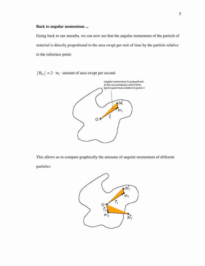
Back to angular momentum ...
Going back to our amoeba, we can now see that the angular momentum of the particle of
material is directly proportional to the area swept per unit of time by the particle relative
to the reference point:
HOi = 2 ⋅ mi ⋅ amount of area swept per second
This allows us to compare graphically the amounts of angular momentum of different
particles:

6
To calculate the angular momentum of the whole system (the whole amoeba!), we would
need to use the equation:
!
HO
= mi(ri " vi )i=1
n
#
A problem with using this equation is that it would require us to compute the angular
momentum values of an infinite number of individual particles. So we are lucky that we
don’t study amoebas!
The human body can be considered a series of rigid segments that can rotate relative to
each other at joints. So the human body is something intermediate between a single rigid
block and an amoeba. We will deal with it later.

7
For now, we will continue developing our equations, to obtain an expression for the
angular momentum of a rigid object.
If all the points of the amoeba were only able to move in circles about point O, we would
have:
!
HO
= miri" v
i
i=1
n
#
= miri" $
i" r
i
i=1
n
#
and thus,
!
HO
= miri
2
"i
i=1
n
#
If all particles also have the same angular velocity vector, we have that:
!
HO
= ( mi ri2)"
i=1
n
#
HO = I ω
This is the traditional formula for angular momentum. We have seen that it can only be
applied to a rigid object rotating in 2D.

8
Angular momentum needs to be calculated about a given point
Angular momentum needs to be calculated about either:
(a) an inertial point, i.e., a point that is static or that translates at constant linear velocity
or
(b) the center of mass of the system. This is valid even if the center of mass does not
have constant linear velocity.
Usually, (b) is the best choice.

9
Calculation of the angular momentum of the human body about its own center of
mass
The human body is considered to be composed of rigid segments that rotate relative to
each other.
Each segment has two angular momentum elements:
remote angular momentum: associated with the motion of the segment’s c.m. about the
c.m. of the whole body
local angular momentum: associated with the motion of the segment about its own c.m.
remote angular momentum = shank mass ⋅ 2 ⋅ area swept per second
(i.e. like amoeba particle)
local angular momentum = shank moment of inertia about own c.m. ⋅ shank angular velocity (i.e. like rigid object)

10
The local terms of angular momentum are usually much smaller than the remote terms.
So if you ignore the local terms, you will have some error but not very much. This is
very useful for qualitative analysis, because the remote terms can be used to make
estimates of the angular momentum of each body segment:
In the tutorial, we will look at the angular momentum of each segment during the
airborne motion of a hitch-kick style (“bicycling”) long jump.
In 2D analysis, clockwise areas indicate an angular momentum vector pointing into the
blackboard; counterclockwise areas indicate an angular momentum vector pointing out
from the blackboard toward us.

11
3D Rotation
Qualitative analysis of angular momentum
There are two possible ways to make a qualitative analysis of angular momentum in a 3D
motion:
(1) Try to make the analysis directly in 3D. This involves visualizing 3D vectors in a
multitude of directions. It’s difficult to do, and generally not a good idea.
(2) Look at the 3D motion as three separate projected 2D motions, by viewing in
succession from three different directions perpendicular to each other. Each of these
orthogonal directions will give us information about the angular momentum vector
component in the direction along the line of sight.

12
Quantitative analysis of angular momentum
Those are the methods that we would use for an intuitive, qualitative approach. To make
accurate calculations with a computer, we would use other methods, as we will see next.
Calculating the remote terms of angular momentum is very simple, both in 2D and 3D
analysis. The formula:
!
HO
= mi(ri " vi )i=1
n
#
would be applied to the linear location and linear velocity of the center of mass of each
segment relative to the whole body center of mass.
In a true 2D motion, calculating the local terms of angular momentum would also be
quite simple. We would just need to multiply each segment’s centroidal moment of
inertia by the segment’s angular velocity about its own center of mass. This is the simple
formula H = I ω.
However, in 3D motion there is a problem for the calculation of the local terms of
angular momentum. The formula H = I ω does not work in 3D motion. We will see
why.

13
Both objects in the drawing above are rotating about a vertical axis, and the angular
velocity vector ω is the same for both.
In the view from the positive Z direction, the particles that constitute the two objects
sweep the same amounts of counterclockwise areas, and in the view along the X axis no
areas are swept at all in either case at the instant shown in the drawing. However, in the
view along the Y axis the object on the left is sweeping no area, while the object on the
right is sweeping counterclockwise areas when viewed from the negative Y direction:
This implies that the object on the left has only a positive Z component of angular
momentum, while the object on the right has a positive Z component and a negative Y
component of angular momentum:
Therefore, in the object on the right the angular velocity and angular momentum vectors
do not point in the same direction. Consequently, H ≠ I ω.
14
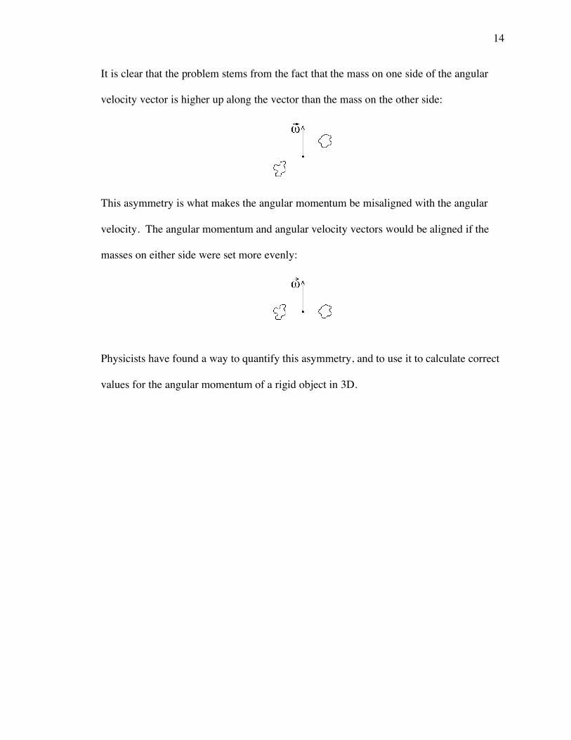
It is clear that the problem stems from the fact that the mass on one side of the angular
velocity vector is higher up along the vector than the mass on the other side:
This asymmetry is what makes the angular momentum be misaligned with the angular
velocity. The angular momentum and angular velocity vectors would be aligned if the
masses on either side were set more evenly:
Physicists have found a way to quantify this asymmetry, and to use it to calculate correct
values for the angular momentum of a rigid object in 3D.

15
Moments of inertia:
!
IXX = dm(Yi2
i=1
n
" + Zi2)
!
IYY = dm(Xi
2
i=1
n
" + Zi2)
!
IZZ = dm(Xi
2
i=1
n
" + Yi2)
Products of inertia:
!
IXY = " dm(Xi #Yii=1
n
$ )
!
IXZ = " dm(Xi # Zii=1
n
$ )
!
IYX = " dm(Yi #Xi
i=1
n
$ )
!
IYZ = " dm(Yi # Zii=1
n
$ )
!
IZX = " dm(Zi #Xi
i=1
n
$ )
!
IZY = " dm(Zi #Yii=1
n
$ )
(NOTE: In some books there are no minus signs before the sigmas in the definitions of the products of
inertia. Such a definition is valid too, but it requires changes also in other equations. Be sure not to mix
the two alternative conventions!)

16
Let’s look at the IXZ product of inertia:
We see that the products of inertia give us good information about the “asymmetry” of
the object.

17
Physicists like to show the moments of inertia and the products of inertia together in an
ordered array:
!
IXX
IXY
IXZ
IYX
IYY
IYZ
IZX
IZY
IZZ
"
# $
% $
&
' $
( $
This is called the tensor of inertia. It’s often designated simply as
!
I{ }.
The formula to calculate the angular momentum of a rigid object using the moments and
products of inertia is the following:
H = IXX ωX + IXY ωY + IXZ ωZ
+ IYX ωX + IYY ωY + IYZ ωZ
+ IZX ωX + IZY ωY + IZZ ωZ
where ωX, ωY and ωZ are the three components of the ω vector.
This can be expressed as the product of two matrices:
!
H =
IXX
IXY
IXZ
IYX
IYY
IYZ
IZX
IZY
IZZ
"
# $
% $
&
' $
( $ )
*X
*Y
*Z
"
# $
% $
&
' $
( $
where
!
"X
"Y
"Z
#
$ %
& %
'
( %
) %
is the angular velocity vector, which can be designated simply as
!
"{ }.

18
So in the end we have that H = {I} {ω}, where {I} and {ω} are actually matrices.
Note that this is not the same as H = I ω, which would not produce the correct results,
because it is missing the terms involving the products of inertia.
Having said all this, it IS possible to calculate the angular momentum of a rigid object in
3D without using the products of inertia!
But before we learn how to do this we need to define the concept of principal axes.

19
Principal axes
20
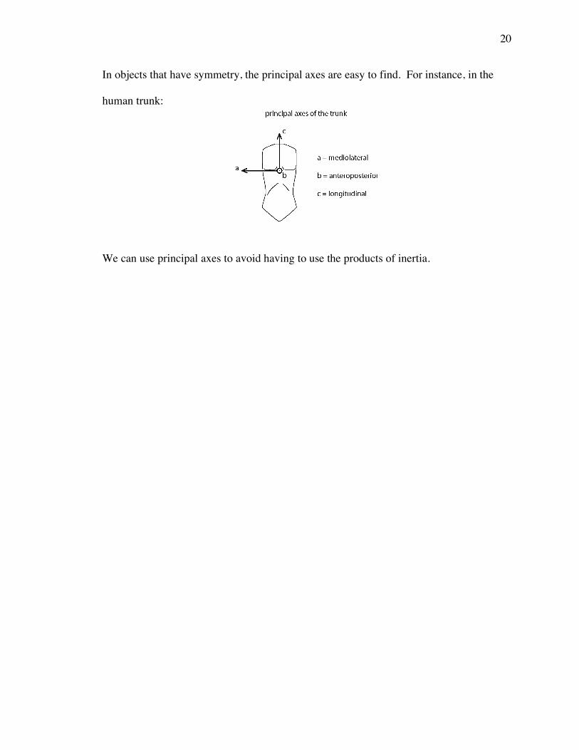
In objects that have symmetry, the principal axes are easy to find. For instance, in the
human trunk:
We can use principal axes to avoid having to use the products of inertia.

21
Calculation of local angular momentum in 3D without using products of inertia
Let’s consider a cylinder with elliptical cross-section to represent the human trunk.
The XYZ axes shown here are not principal axes. They are parallel to the axes of the
reference frame attached to the ground.
The standard equation to calculate angular momentum is:
!
H =
IXX
IXY
IXZ
IYX
IYY
IYZ
IZX
IZY
IZZ
"
# $
% $
&
' $
( $ )
*X
*Y
*Z
"
# $
% $
&
' $
( $
We will now show a temporary non-rotating reference frame abc such that axes a, b and c
happen to coincide instantaneously with the principal axes of the cylinder:

22
The angular velocity of the cylinder will first be calculated in terms of the XYZ reference
frame attached to the ground, using standard film analysis or video analysis procedures.
Then, we can choose to express the angular velocity of the cylinder in terms of the abc
reference frame,. If we do this, we will have:
!
H =
Iaa
Iab
Iac
Iba
Ibb
Ibc
Ica
Icb
Icc
"
# $
% $
&
' $
( $ )
*a
*b
*c
"
# $
% $
&
' $
( $
But, since axes a, b and c are principal axes, the products of inertia are zero. Therefore:
!
H =
Iaa
0 0
0 Ibb
0
0 0 Icc
"
# $
% $
&
' $
( $ )
*a
*b
*c
"
# $
% $
&
' $
( $
= Iaa ωa + Ibb ωb + Icc ωc
For instance, if:
Iaa = 1.4 Ibb = 1.6 Icc = 0.5
and if:
ωa = 27 ua ωb = 31 ub ωc = 45 uc
where ua, ub and uc are the unit vectors of the abc reference frame, we would have:
H = (1.4 ⋅ 27) ua + (1.6 ⋅ 31) ub + (0.5 ⋅ 45) uc
= 37.8 ua + 49.6 ub + 22.5 uc Kg ⋅ m2/s

23
So that would be the angular momentum value that we were looking for. But there is a
slight problem: This angular momentum vector is expressed in terms of the abc reference
frame instead of the XYZ reference frame, which is inconvenient. But this problem is
actually very easy to solve.
Remember that the angular velocity vector was initially expressed in terms of the XYZ
reference frame. When we project this vector onto the a, b and c axes, the ωa, ωb and ωc
vectors that we get will each be expressed still in terms of the XYZ reference frame. For
instance, we could have:
ωa = 27 ua = 19.2 uX + 16.9 uY + 8.8 uZ (for example!)
ωb = 31 ub = -19.7 uX + 23.8 uY - 2.8 uZ (for example!)
ωc = 45 uc = -13.7 uX – 6.4 uY + 42.4 uZ (for example!)
where uX, uY and uZ are the unit vectors of the XYZ reference frame
In such case, the value of the angular momentum vector would be:
H = 1.4 ⋅ (19.2 uX + 16.9 uY + 8.8 uZ)
+ 1.6 ⋅ (-19.7 uX + 23.8 uY - 2.8 uZ)
+ 0.5 ⋅ (-13.7 uX – 6.4 uY + 42.4 uZ)
= -11.5 uX + 58.5 uY + 29.0 uZ Kg ⋅ m2/s
So, in effect, we are using H = Iaa ωa + Ibb ωb + Icc ωc, but with ωa, ωb and ωc expressed
in terms of the XYZ reference frame, which is a trivial thing to do, as we have seen.

24
That is how we would calculate the local angular momentum of the trunk about its own
c.m.
The other segments are usually considered cylinders of circular (instead of elliptical)
cross-section. So for them the longitudinal axis is clearly defined, but there are infinite
possible orientations for the other two axes. Any two axes will do, as long as they are
both perpendicular to the longitudinal axis and perpendicular to each other. This
ambiguity allows us to calculate the local terms of angular momentum of these segments
with even greater ease than for the trunk.
We will pick the a or the b axis to be in the plane defined by ω and by the longitudinal
axis c. For instance, let’s assume that we choose to make the a axis be in that plane:
In this case, ωb will be zero. Therefore:
H = Iaa ωa + Icc ωc
where ωa and ωc will be expressed in terms of the XYZ reference frame.

25
Angular momentum of the whole body:
H =
!
i=1
14
" mi (ri × vi) ← remote terms
+
!
i=1
13
" ILONGi ωTWi + ITRANSVi ωSOMi ← non-trunk local terms
+ ILONG14 ωTW14 + IML14 ωSOM-ML14 + IAP14 ωSOM-AP14 ← trunk local term

26
References
For the representation of angular momentum by areas swept, see:
Hopper, Bernard J. The mechanics of human movement. American Elsevier, 1973.
This excellent book is out of print, but you may find it at a library. Or you can purchase a
used copy through Internet. For instance, try at:
http://www.amazon.com/exec/obidos/subst/books/misc/bibliofind.html
or at:
http://www.abebooks.com
For the computation of 3D angular momentum, see:
Dapena, J. A method to determine the angular momentum of a human body about
three orthogonal axes passing through its center of gravity. Journal of
Biomechanics 11:251-256, 1978.