3D Printing Technology
32
Seminar Report 2007-08 3D Printing Technology ACKNOWLEDGEMENT I would like to thank everyone who helped to see this seminar to completion. In particular, I would like to thank my seminar coordinator, Prof. T Valsalan for the moral support and guidance to complete my seminar on time. Also I would like to thank Mr. T. Anil Kumar (Lecturer in EEE) for his valuable help and support. I express my gratitude to all my friends and classmates for their support and help in this seminar. Last, but not the least I wish to express my gratitude to God almighty for his abundant blessings, without which this seminar would not have been successful. Dept. of Electrical & Electronics Engg. Govt. College of Engg., Kannur
-
Upload
praveenpv7 -
Category
Documents
-
view
103 -
download
4
Transcript of 3D Printing Technology

Seminar Report 2007-08 3D Printing Technology
ACKNOWLEDGEMENT
I would like to thank everyone who helped to see this seminar to completion. In
particular, I would like to thank my seminar coordinator, Prof. T Valsalan for the moral
support and guidance to complete my seminar on time. Also I would like to thank
Mr. T. Anil Kumar (Lecturer in EEE) for his valuable help and support.
I express my gratitude to all my friends and classmates for their support and help in
this seminar.
Last, but not the least I wish to express my gratitude to God almighty for his
abundant blessings, without which this seminar would not have been successful.
Dept. of Electrical & Electronics Engg. Govt. College of Engg., Kannur

Seminar Report 2007-08 3D Printing Technology
ABSTRACT
The last two decades ended in the midst of revolution caused by a technology that
was barely noticeable at the beginning of the decade. In 1980 few would have guessed
that personal computer along with desktop publishing software would fundamentally
change the way of our industry did business. In 1990 again internet was known and used
by a relatively small set of people. Yet by the end of the decade it was a major force in
our industry and in society and in economy.
Once again we are facing anew decade and we have to wonder what the next
dominant technology likely to change our way of life is. While there is a number of
candidates for the ”next big technology” including perennial favorite, the free energy
device, our best is the technology called 3D printing which as the name implies is a
technology that literally prints real 3D objects. It is used by the marketing industry to
create models for marketing focus groups and pre-production sales demonstration.
Dept. of Electrical & Electronics Engg. Govt. College of Engg., Kannur

Seminar Report 2007-08 3D Printing Technology
CONTENTS
CHAPTER 1 INTRODUCTION 1
1.1 HISTORY 2
1.2 SOURCE DATA 2
CHAPTER 2 AN OVERVIEW OF 3D PRINTING TECHNOLOGY 4
2.1 BLOCK DIAGRAM 4
2.2 WORKING 6
2.3 COLOUR MODELLING 8
CHAPTER 3 APPLICATIONS AND SPECIFICATIONS 9
3.1 ADVANTAGES 9
3.2 BUILDING MATERIALS 11
3.3 SPECIFICATIONS 14
3.4 APPLICATIONS 15
CHAPTER 4 CONCLUSION 16
REFERENCE 17
Dept. of Electrical & Electronics Engg. Govt. College of Engg., Kannur

Seminar Report 2007-08 3D Printing Technology
CHAPTER 1
INTRODUCTION
Originally developed at the Massachusetts Institute of Technology (MIT) in
1993, .3DP technology creates 3D physical prototypes by solidifying layers of deposited
powder using a liquid binder. By definition 3DP is an extremely versatile and rapid
process accommodating geometry of varying complexity in hundreds of different
applications, and supporting many types of materials. Utilizing 3DP technology, Z Corp.
has developed 3D printers that operate at unprecedented speeds, extremely low costs, and
within a broad range of applications. 3D printers are used by leading manufacturers to
produce early concept models and product prototypes .This paper describes the core
technology and its related applications.
Dept. of Electrical & Electronics Engg. Govt. College of Engg., Kannur1

Seminar Report 2007-08 3D Printing Technology
1.1 HISTORY
3d printing technology was originally developed in Massachusetts Institute of
Technology. First 3 D Printer was launched in 1998. First 3D color printer was launched in
2000. Introduced High definition 3D Printing in 2005. HD3DP concept is the result of a
combination of print-head technology, materials advancement, firmware, and mechanical
design.
1.2 SOURCE DATA
3D printing technology leverages 3D source data, which often takes the form of
computer-aided design (CAD) models. Mechanical CAD software packages, the first
applications to create 3D data, have quickly become the standard for nearly all product
development processes. Other industries such as architectural design have also embraced
3D technologies because of the overwhelming advantages they provide, including improved
visualization, greater automation, and more cost-effective reuse of 3D data for a variety of
critically important applications. Due to the widespread adoption of 3D-based design
technologies, most industries today already create 3D design data and are capable of
producing physical models with 3D printers. The software that drives the 3D printers
accepts all major 3D file formats, including .stl, .wrl, .ply, and .sfx files, which leading 3D
software packages can export. In addition to mainstream applications in mechanical and
architectural design, 3D printing has expanded into new markets including medical,
molecular, and geospatial modeling. Additional sources of data include CT/MRI diagnostic
data, protein molecule modeling database data, and digitized 3D-scan data. As designing
and modeling with 3D technologies has become more pervasive, developers have created a
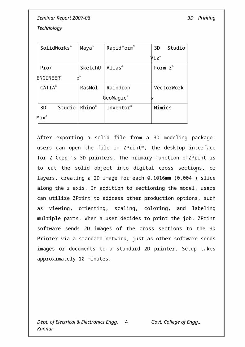
large number of software packages tailored for use in specific industries. A small sampling
of 3D software packages that are directly compatible with the 3D printers appear in the
table below.
Dept. of Electrical & Electronics Engg. Govt. College of Engg., Kannur2

Seminar Report 2007-08 3D Printing Technology
SolidWorks® Maya® RapidForm™ 3D Studio Viz®
Pro/ENGINEER® SketchUp® Alias® Form Z®
CATIA® RasMol Raindrop GeoMagic® VectorWorks
3D Studio Max® Rhino® Inventor® Mimics
After exporting a solid file from a 3D modeling package, users can open the file in
ZPrint™, the desktop interface for Z Corp.’s 3D printers. The primary function ofZPrint
is to cut the solid object into digital cross sections, or layers, creating a 2D image for each
0.1016mm (0.004”) slice along the z axis. In addition to sectioning the model, users can
utilize ZPrint to address other production options, such as viewing, orienting, scaling,
coloring, and labeling multiple parts. When a user decides to print the job, ZPrint
software sends 2D images of the cross sections to the 3D Printer via a standard network,
just as other software sends images or documents to a standard 2D printer. Setup takes
approximately 10 minutes.
Dept. of Electrical & Electronics Engg. Govt. College of Engg., Kannur3

Seminar Report 2007-08 3D Printing Technology
CHAPTER 2
AN OVERVIEW OF 3D PRINTING TECHNOLOGY
2.1BLOCK DIAGRAM
The microcomputer is used to create a 3 Dimensional model of the
component to be made using well-known CAD techniques. A slicing
algorithm is used to identify selected successive slices, i.e., to provide data
with respect to selected 2-D layers, of the 3-D model.
Once a particular 2–D slice has been selected, the slice is then reduced
to a series of one dimensional scan lines. Each of the scan line may comprise
of single line segments or two or more shorter line segments. Each line
segment having a defined starting point on a scan line and a defined line
segment length.
The microcomputer actuates the powder distribution operation when a
particular 2-D slice of the 3-D model which has been created has been
selected by supplying a powder “START” signal to a powder distribution
controller circuit which is used to actuate a powder distribution system to
permit a layer of powder for the selected slice to be deposited as by a powder
head device. The powder is deposited over the entire confined region within
which the selected slice is located.
Once the powder is distributed, the operation of powder distribution
controller is stopped when the microcomputer issues a powder “STOP”
signal signifying that powder distribution over such region has been
completed.
Microcomputer then select a scan line i.e., the first scan line of the
selected 2-D slice and then select a line segment, e.g., the first 1-D line
segment of the selected scan line and supplies data defining the starting point
thereof and the length thereof to a binder jet nozzle control circuit. For
Dept. of Electrical & Electronics Engg. Govt. College of Engg., Kannur4
Seminar Report 2007-08 3D Printing Technology
simplicity in describing the operation it is assumed that a single binder jet
nozzle is used and that such nozzle scans the line segment of a slice in a
manner such that the overall 2-D slice is scanned in a conventional raster
scan operation. When the real time position of the nozzle is at starting point
of the selected line segment. Nozzle is turned on at the start of the line
segment and turned off at the end of line segment in accordance with the
defined starting point and length data supplied from the computer for that
line segment. Each successive line segment is similarly scanned for the
selected scan line and for each successive scan line of the selected slice in
the same manner. For such purpose nozzle carrier system starts its motion
with a scan “BEGIN” signal from microcomputer. So that it is moved in both
x-axis direction and in the Y-axis direction. Data as to the real time position
of the nozzle carrier is supplied to the nozzle control circuit. When the
complete slice has been scanned, a scan “STOP” signal signifies an end of
the slice scan condition.
Dept. of Electrical & Electronics Engg. Govt. College of Engg., Kannur5

Seminar Report 2007-08 3D Printing Technology
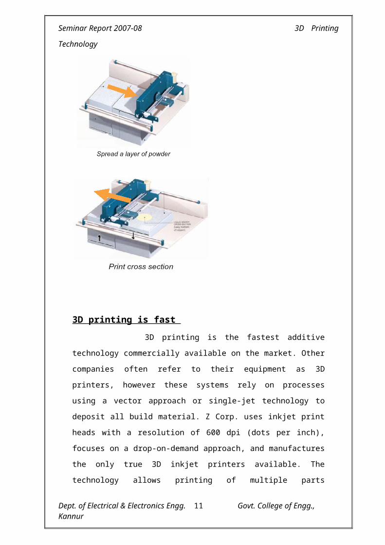
2.2 3D PRINTING WORKING
3D printers use standard inkjet printing technology to create parts layer-
by-layer by depositing a liquid binder onto thin layers of powder. Instead of
feeding paper under the print heads like a 2D printer, a 3D printer moves the
print heads over a bed of powder upon which it prints the cross-sectional data
sent from the ZPrint software. The system requires powder to be distributed
accurately and evenly across the build platform. 3D Printers accomplish this task
by using a feed piston and platform, which rises incrementally for each layer. A
roller mechanism spreads powder fed from the feed piston onto the build
platform; intentionally spreading approximately 30 percent of extra powder per
layer to ensure a full layer of densely packed powder on the build platform. The
excess powder falls down an overflow chute, into a container for reuse in the
next build.
Once the layer of powder is spread, the inkjet print heads print the cross-
sectional area for the first, or bottom slice of the part onto the smooth layer of
powder, binding the powder together. A piston then lowers the build platform
0.1016mm (0.004”), and a new layer of powder is spread on top. The print heads
apply the data for the next cross section onto the new layer, which binds itself to
the previous layer. ZPrint repeats this process for all of the layers of the part. The
3D printing process creates an exact physical model of the geometry represented
by 3D data. Process time depends on the height of the part or parts being built.
Typically, 3D printers build at a vertical rate of 25mm – 50mm (1” – 2”) per
hour.
When the 3D printing process completes, loose powder surrounds and
supports the part in the build chamber. Users can remove the part from the build
chamber after the materials have had time to set, and return unprinted, loose
powder back to the feed platform for reuse. Users then use forced air to blow the
excess powder off the printed part, a short process which takes less than 10
minutes. Z Corp. technology does not require the use of solid or attached
supports during the printing process, and all unused material is reusable.
Dept. of Electrical & Electronics Engg. Govt. College of Engg., Kannur6

Seminar Report 2007-08 3D Printing Technology
3D printing is fast
3D printing is the fastest additive technology commercially available on
the market. Other companies often refer to their equipment as 3D printers,
however these systems rely on processes using a vector approach or single-jet
technology to deposit all build material. Z Corp. uses inkjet print heads with a
resolution of 600 dpi (dots per inch), focuses on a drop-on-demand approach,
and manufactures the only true 3D inkjet printers available. The technology
allows printing of multiple parts simultaneously, while only adding a negligible
amount of time to the print time for one part.
The fundamental inkjet approach is the primary contributor to greater
speed, although there are several other reasons why this system is the fastest.
ZPrint software processes data in parallel with the printing of the part. While the
3D printer deposits the first layer, the software slices and processes the fifth
layer. Some additive technologies process all tool paths before the job begins.
Dept. of Electrical & Electronics Engg. Govt. College of Engg., Kannur7

Seminar Report 2007-08 3D Printing Technology
Although the processing time may seem to be fast, it is often only a fraction of
the total time it takes to build the part. It can actually take up to an hour to
prepare a job with multiple parts using some additive technologies.
3D printers enable the stacking of parts vertically because they do not require
rigid support structures. Producing parts with other types of additive
technologies requires structural supports along the vertical axis, limiting the
ability to stack or nest parts. With this 3D printers, users can utilize the entire
build area and produce multiple parts with only one set-up procedure, further
reducing the total number of builds and processing time.
2.3 COLOUR MODELLING
When printing 2D images from digital files, computers convert the RGB
values (Red, Green, and Blue colors displayed on the monitor) to CMYK colors
(Cyan, Magenta, Yellow, and Black). Typically, a 2D color desktop printer will
have a print head with three of the color channels, CMY, and another for black,
K. Using these four inks, the printer combines several dots in each printed pixel
though the use of ordered dither patterns to create the appearance of thousands of
colors. The same principle applies to 3D printing. 3D printers use four colored
binders: cyan, magenta, yellow and clear, to print colors onto the shell of the
part. ZPrint software communicates color information to the printer within the
slice data. Full-color 3D printing produces prototypes with the same coloring as
the actual product. Users also use color to represent analysis results directly on
the model or to annotate and label design changes to further enhance the
communication value of the model.
While color can be an essential communications tool, many 3D software
packages do not provide a simple way to produce 3D files that include color
data. To address this challenge developed ZEdit™ software, a Microsoft®
Windows® based program that facilitates the addition of color data to 3D part
files. ZEdit is a tool for part coloring, markup, labeling, and texture mapping.
Users also utilize it to map .jpeg files onto 3D part geometries. ZEdit software
works with files from any of the leading 3D software packages.
Dept. of Electrical & Electronics Engg. Govt. College of Engg., Kannur8

Seminar Report 2007-08 3D Printing Technology
Z Corp.’s 3D printers produce high-resolution models
Z Corp. first introduced high-resolution 3D Printing (HD3DP™) in 2005.
The HD3DP concept is the result of a combination of print-head technology,
materials advancement, firmware, and mechanical design. Highly engineered
inkjet print heads, with 600-dpi, high-resolution capabilities, are the product of
years of research. Z Corp. leverages the engineered print heads in combination
with proprietary firmware to control the print head during the printing process,
accurately and precisely depositing colored binder in the areas indicated by the
ZPrint software. Additionally, this 3D printers control the print head movement
while positioned extremely close to the powder, reducing inaccuracies related to
fanning of the binder spray.
CHAPTER 3
APPLICATIONS AND SPECIFICATIONS
3.1 ADVANTAGES
1) 3D printing is Affordable
3D printers produce very little waste. The unprinted powder surrounds
and supports complex parts during printing. Users can reuse all unused support
powder. Thus, printed-part volume becomes the basis for all part-creation costs.
Other additive processes require the building of solid support structures to
support complex geometries during the printing process. Users have to discard
these support structures after use, and the wasted material contributes
significantly to the cost of additive technologies.
3D printers are dependable and easy-to-use, resulting in low operating
costs. Modular design and standard inkjet printing technology combine to
produce a reliable system that is straightforward to operate and easy to maintain.
The use of an “off-the-shelf” print head allows for inexpensive, quick
replacement of the system’s primary consumable component. The application of
modular design techniques to the printer’s electronics, printing, and maintenance
Dept. of Electrical & Electronics Engg. Govt. College of Engg., Kannur9

Seminar Report 2007-08 3D Printing Technology
components makes the printers efficient to maintain with minimum downtime,
further reducing costs.
2) 3D printers are easy to use
The straightforward user interface and simple part-making process
make 3D printers accessible to everyone involved in product design. The
materials used are non-toxic, completely safe, and do not require specialized
operating environments such as a lab or a shop. Users can operate 3D printers
right in an office rather than in a designated space with specialized requirements.
Because of the intuitive ZPrint software interface and simple set-up procedures,
anyone can efficiently operate one of 3D printers, eliminating the need for a
dedicated machine operator. The reliable technology allows its 3D printers to
run unattended during the printing process, reducing user interaction to the
simple setup and part removal steps, which generally take less than one hour.
The process of bonding loose powder to solidify into parts is compatible
with many types of materials. While the 3D printer remains exactly the same,
users can change the build material to produce parts with a wide range of
material properties to meet various application requirements. Z Corp. offers five
materials and continues to develop other materials to provide performance
enhancements for additional applications. Users can select the best material to
support the needs of a specific application.
3) Speed
3D Printers are the fastest.5-10x faster than other RP technology.A part
can be printed at rate of 25mm vertical per hour. In todays competitive global
market speed in product development has become a critical factor for success.
4) Affordability
Z Corporation® sets the standard for affordability in 3D printing.
Because Z Corporation printers leverage standard inkjet printing technology,
they are more reliable and affordable. The approach results in material usage
costs that are a fraction of other rapid prototyping technologies; finished parts
cost $.10 USD per cubic centimeter in materials. A handheld part can be
produced for about $10 USD in material costs. Z Corporation 3D printers recycle
Dept. of Electrical & Electronics Engg. Govt. College of Engg., Kannur10

Seminar Report 2007-08 3D Printing Technology
all unused material, so you only pay for the actual materials used to produce a
part.
5) High-Quality Color
Z Corporation 3D Printers operate like a 2D desktop inkjet printer,
allowing for the use of multiple print-heads to support full-color printing with
dramatic increases in speed. Full,24-bit color capabilities use colored binder
materials (cyan, magenta, and yellow, just like a 2D printer) to produce millions
of distinct colors. Full-color printing allows the addition of annotations,
engineering labels and texture maps. Z Corporation’s introduction ofHD3DP
(High-Definition 3D Printing) capabilities also supports the production of
models having complex geometries and small, detailed features.
6) Versatile
The process of bonding loose powder to solidify into parts is compatible
with many types of materials.While the 3D printer remains exactly the
same.users can change the build material to produce part with wide range of
material property to meet various application requirement.
3.2 BUILDING MATERIALS
1) High-Performance Composite Material makes strong, high-definition
parts and is the material of choice for printing color parts. The most widely
used material, high-performance composite material enables color HD3DP on
the 600-dpi platform 3D printer. Fine resolution on small features and excellent
strength make this material suitable for applications ranging from concept
modeling to sand-casting patterns. It consists of a heavily engineered plaster
material with numerous additives that maximize surface finish, feature
resolution, and part strength. This material is ideal for:
• High-strength requirements
• Delicate or thin-walled parts
• Color printing
• Accurate representation of design details
Dept. of Electrical & Electronics Engg. Govt. College of Engg., Kannur11
Seminar Report 2007-08 3D Printing Technology
2) Direct Casting Metal Material creates sand-casting molds for non-ferrous
metals. This material is a blend of foundry sand, plaster, and other additives that
when combined produce strong molds with good surface finishes. Direct casting
metal material can withstand the heat required to cast non-ferrous metals. Users
of this “ZCast®” process can create prototype castings without incurring the costs
and lead-time delays of tooling.
Dept. of Electrical & Electronics Engg. Govt. College of Engg., Kannur12

Seminar Report 2007-08 3D Printing Technology
3) Investment Casting Material fabricates parts that users dip in wax to
produce investment casting patterns without molds or geometric constraints.
The material consists of a mix of cellulose, specialty fibers, and other
additives that combine to provide an accurate part while maximizing wax
absorption and minimizing residue during the burn-out process. Users
utilize investment casting material to create high quality castings with
excellent surface finishes in a number of industries.
4) Snap-fit material creates Snap- parts with plastic-like, flexural
properties, Which are ideal for snap-fit applications. Z Corp. has optimized
this material for infiltration with the Z-Snap™ epoxy. Users utilize snap-fit
material to create plastic-like parts that snap into other components and
assemblies.
5) Elastomeric Material creates parts with rubber-like properties.
Optimized for infiltration with an elastomer, this material system consists of
a mix of cellulose, specialty fibers, and other additives. Users utilize
elastomeric material to produce accurate parts that are capable of absorbing
the elastomer, which gives the parts their rubber-like properties.
The microcomputer is used to create a 3 Dimensional model of the
component to be made using well-known CAD techniques.A slicing
algorithm is used to identify selected successive slices, i.e., to provide data
with respect to selected 2-D layers, of the 3-D model.
Once a particular 2–D slice has been selected, the slice is then
reduced to a series of one dimensional scan lines. Each of the scan line may
comprise of single line segments or two or more shorter line segments.Each
line segment having a defined starting point on a scan line and a defined line
segment length.
The microcomputer actuates the powder distribution operation when a
particular 2-D slice of the 3-D model which has been created has been
Dept. of Electrical & Electronics Engg. Govt. College of Engg., Kannur13

Seminar Report 2007-08 3D Printing Technology
selected by supplying a powder “START” signal to a powder distribution
controller circuit which is used to actuate a powder distribution system to
permit a layer of powder for the selected slice to be deposited as by a powder
head device. The powder is deposited over the entire confined region within
which the selected slice is located.
Once the powder is distributed, the operation of powder distribution
controller is stopped when the microcomputer issues a powder “STOP”
signal signifying that powder distribution over such region has been
completed.
Microcomputer then select a scan line i.e., the first scan line of the
selected 2-D slice and then select a line segment, e.g., the first 1-D line
segment of the selected scan line and supplies data defining the starting point
thereof and the length thereof to a binder jet nozzle control circuit. For
simplicity in describing the operation it is assumed that a single binder jet
nozzle is used and that such nozzle scans the line segment of a slice in a
manner such that the overall 2-D slice is scanned in a conventional raster
scan operation.
Dept. of Electrical & Electronics Engg. Govt. College of Engg., Kannur14

Seminar Report 2007-08 3D Printing Technology
3.3 SPECIFICATION
Some of 3D printers available in the market are 1) Z printer 310
2) Spectrum Z 510 3) Z printer 45
1) Z printer 310 [Industrial strandate Monochrome
3D printing system]
Equipment Dimension
74 * 86 * 109cm
Equipment weight
115 Kg
Power Requirement
115 V, 4.3 A or 230 V / 2.4 A
Resolution; 300 * 450 dpi
Build speed; 2 – 4 layers per minute
2) Spectrum Z-510 [next generation H D colour 3DP]
Equipment Dimension: 107 * 79 * 127cm
Equipment weight - 204 Kg
Resolution-600*540dpi
Power-100V, 7.8A or 115V, 6.8A or 230V, 3.4A
Dept. of Electrical & Electronics Engg. Govt. College of Engg., Kannur15

Seminar Report 2007-08 3D Printing Technology
3.4 APPLICATION
1. Concept modeling
2. Finite Element Analysis
3. Functional Testing
4. Metal Casting
5. Presantation Models
Dept. of Electrical & Electronics Engg. Govt. College of Engg., Kannur16

Seminar Report 2007-08 3D Printing Technology
CHAPTER 4
CONCLUSION
3D Printing is the method of converting virtual 3D models into physical
model. After the arrival of 3D Printing futurist predicted that we’d soon see them
in every home. In future consumers will probably make what they want at home
with their own 3D Printers. If some want a latest fashion toy. They will buy the
3D file instead of the product. One day we may have 3D Printer that use
nanotechnology to create products by depositing them atom by atom. Simple
machinery has been created at the atomic scale such as small wheels, transistors
and “walking DNA”. These could be the precursors to more advanced custom
manufacturing system.
Dept. of Electrical & Electronics Engg. Govt. College of Engg., Kannur17

Seminar Report 2007-08 3D Printing Technology
REFERENCE
1. http://www.emco.co.uk/rapid.htm
2,http://www.hawkridgesis.com/products/p.add.z corps.htm/
3. http://www.sldtech.com/PDFs/3D printers Brochure overviews.pdf
4. www.architecture.mit .edu.
5. www.realizationgroup.com
Dept. of Electrical & Electronics Engg. Govt. College of Engg., Kannur18