3D printing of complex origami assemblages for ... · complex 3D origami structures, for example,...
9
This journal is © The Royal Society of Chemistry 2018 Soft Matter, 2018, 14, 8051--8059 | 8051 Cite this: Soft Matter, 2018, 14, 8051 3D printing of complex origami assemblages for reconfigurable structures† Zeang Zhao, ab Xiao Kuang, a Jiangtao Wu, a Qiang Zhang, b Glaucio H. Paulino,* c H. Jerry Qi * a and Daining Fang* bd Origami engineering principles have recently been applied to a wide range of applications, including soft robots, stretchable electronics, and mechanical metamaterials. In order to achieve the 3D nature of engineered structures (e.g. load-bearing capacity) and capture the desired kinematics (e.g., foldability), many origami-inspired engineering designs are assembled from smaller parts and often require binding agents or additional elements for connection. Attempts at direct fabrication of 3D origami structures have been limited by available fabrication technologies and materials. Here, we propose a new method to directly 3D print origami assemblages (that mimic the behavior of their paper counterparts) with acceptable strength and load-bearing capacity for engineering applications. Our approach introduces hinge-panel elements, where the hinge regions are designed with finite thickness and length. The geometrical design of these hinge-panels, informed by both experimental and theoretical analysis, provides the desired mechanical behavior. In order to ensure foldability and repeatability, a novel photocurable elastomer system is developed and the designs are fabricated using digital light processing-based 3D printing technology. Various origami assemblages are produced to demonstrate the design flexibility and fabrication efficiency offered by our 3D printing method for origami structures with enhanced load bearing capacity and selective deformation modes. 1. Introduction Origami, the traditional art of folding paper, has the potential to inform the design of novel engineered structures. In addition to unique intrinsic properties possessed by some origami tessellations ( e.g. , negative Poisson’s ratio, spatial expandability 1,2 ), other properties such as tunable thermal expansion, 3 program- mable stiffness, 4 spatial curvature, 5 and multistability, 6 can be introduced through geometrical and material variations. These distinct properties of origami lead to a wide range of potential applications, including soft robots, 7 stretchable electronics, 8,9 metamaterials, 10,11 and optical devices. 12 Inspired by the field of origami engineering, unit cells of origami tessellations have been repeated in multiple directions in order to fill a predetermined space and fulfill the requirements of load-bearing capacity, stability, and foldability. The simplest method consists of stacking an origami tessellation in a single direction; 2,13,14 but, in this case, design freedom is restricted because stacking is only applicable to some 2D periodic origami systems such as the Miura-ori. Recently, other cellular origami structures were developed by repeating the unit cells in different directions and assembling them into 3D shapes. 15,16 One such design is the tube unit cell composed of two Miura unit cells (Fig. 1A). The tube unit cell is geometrically simple and, when repeated in an aligned 17 or zipper 18 fashion (Fig. 1B), can con- form to various 3D contours. 18–21 The zipper coupled tubes have outstanding mechanical behavior, in which load-bearing capacity and expandability can be realized at the same time. 18,20 Most origami designs have been fabricated by assembling thin sheets made from either paper, 18 plastic, 22 or metal 14 into 3D origami structures, leading to a tedious process and often requiring additional binders or connection elements. 23,24 Recent research has also demonstrated that self-folding 25,26 a The George W. Woodruff School of Mechanical Engineering, Georgia Institute of Technology, Atlanta, GA 30332, USA. E-mail: [email protected] b State Key Laboratory for Turbulence and Complex Systems, College of Engineering, Peking University, Beijing, 100871, P. R. China. E-mail: [email protected] c School of Civil and Environmental Engineering, Georgia Institute of Technology, Atlanta, GA 30332, USA. E-mail: [email protected] d Institute of Advanced Structure Technology, Beijing Institute of Technology, Beijing, 100081, P. R. China. E-mail: [email protected] † Electronic supplementary information (ESI) available: Properties of the photo- curable elastomer; derivation of the nonlinear beam (NB) theory; the assembly method of two adjacent origami tubes; the mechanical reliability of the hinge-panel element; geometry parameters of 3D printed origami assemblages; repeatability of the printed origami assemblages; additional information of the printed origami assemblages (PDF). Folding process of the aligned origami tubes and the zipper- coupled origami tubes (MP4). Load-bearing capacity of the aligned origami bridge and the zipper-coupled origami bridge (MP4). Folding process of the square/ hexagon coupled origami assemblages (MP4). See DOI: 10.1039/c8sm01341a Received 30th June 2018, Accepted 17th September 2018 DOI: 10.1039/c8sm01341a rsc.li/soft-matter-journal Soft Matter PAPER Published on 17 September 2018. Downloaded by Georgia Institute of Technology on 10/25/2018 3:32:10 PM. View Article Online View Journal | View Issue
Transcript of 3D printing of complex origami assemblages for ... · complex 3D origami structures, for example,...

This journal is©The Royal Society of Chemistry 2018 Soft Matter, 2018, 14, 8051--8059 | 8051
Cite this: SoftMatter, 2018,
14, 8051
3D printing of complex origami assemblagesfor reconfigurable structures†
Zeang Zhao,ab Xiao Kuang,a Jiangtao Wu,a Qiang Zhang,b Glaucio H. Paulino,*c
H. Jerry Qi *a and Daining Fang*bd
Origami engineering principles have recently been applied to a wide range of applications, including soft
robots, stretchable electronics, and mechanical metamaterials. In order to achieve the 3D nature of
engineered structures (e.g. load-bearing capacity) and capture the desired kinematics (e.g., foldability),
many origami-inspired engineering designs are assembled from smaller parts and often require binding
agents or additional elements for connection. Attempts at direct fabrication of 3D origami structures
have been limited by available fabrication technologies and materials. Here, we propose a new method
to directly 3D print origami assemblages (that mimic the behavior of their paper counterparts) with
acceptable strength and load-bearing capacity for engineering applications. Our approach introduces
hinge-panel elements, where the hinge regions are designed with finite thickness and length. The
geometrical design of these hinge-panels, informed by both experimental and theoretical analysis, provides
the desired mechanical behavior. In order to ensure foldability and repeatability, a novel photocurable
elastomer system is developed and the designs are fabricated using digital light processing-based 3D
printing technology. Various origami assemblages are produced to demonstrate the design flexibility and
fabrication efficiency offered by our 3D printing method for origami structures with enhanced load bearing
capacity and selective deformation modes.
1. Introduction
Origami, the traditional art of folding paper, has the potentialto inform the design of novel engineered structures. In additionto unique intrinsic properties possessed by some origamitessellations (e.g., negative Poisson’s ratio, spatial expandability1,2),other properties such as tunable thermal expansion,3 program-mable stiffness,4 spatial curvature,5 and multistability,6 can be
introduced through geometrical and material variations.These distinct properties of origami lead to a wide rangeof potential applications, including soft robots,7 stretchableelectronics,8,9 metamaterials,10,11 and optical devices.12
Inspired by the field of origami engineering, unit cells oforigami tessellations have been repeated in multiple directionsin order to fill a predetermined space and fulfill the requirementsof load-bearing capacity, stability, and foldability. The simplestmethod consists of stacking an origami tessellation in a singledirection;2,13,14 but, in this case, design freedom is restrictedbecause stacking is only applicable to some 2D periodic origamisystems such as the Miura-ori. Recently, other cellular origamistructures were developed by repeating the unit cells in differentdirections and assembling them into 3D shapes.15,16 One suchdesign is the tube unit cell composed of two Miura unit cells(Fig. 1A). The tube unit cell is geometrically simple and, whenrepeated in an aligned17 or zipper18 fashion (Fig. 1B), can con-form to various 3D contours.18–21 The zipper coupled tubes haveoutstanding mechanical behavior, in which load-bearing capacityand expandability can be realized at the same time.18,20
Most origami designs have been fabricated by assemblingthin sheets made from either paper,18 plastic,22 or metal14 into3D origami structures, leading to a tedious process and oftenrequiring additional binders or connection elements.23,24
Recent research has also demonstrated that self-folding25,26
a The George W. Woodruff School of Mechanical Engineering, Georgia Institute of
Technology, Atlanta, GA 30332, USA. E-mail: [email protected] State Key Laboratory for Turbulence and Complex Systems, College of
Engineering, Peking University, Beijing, 100871, P. R. China.
E-mail: [email protected] School of Civil and Environmental Engineering, Georgia Institute of Technology,
Atlanta, GA 30332, USA. E-mail: [email protected] Institute of Advanced Structure Technology, Beijing Institute of Technology,
Beijing, 100081, P. R. China. E-mail: [email protected]
† Electronic supplementary information (ESI) available: Properties of the photo-curable elastomer; derivation of the nonlinear beam (NB) theory; the assemblymethod of two adjacent origami tubes; the mechanical reliability of the hinge-panelelement; geometry parameters of 3D printed origami assemblages; repeatability ofthe printed origami assemblages; additional information of the printed origamiassemblages (PDF). Folding process of the aligned origami tubes and the zipper-coupled origami tubes (MP4). Load-bearing capacity of the aligned origami bridgeand the zipper-coupled origami bridge (MP4). Folding process of the square/hexagon coupled origami assemblages (MP4). See DOI: 10.1039/c8sm01341a
Received 30th June 2018,Accepted 17th September 2018
DOI: 10.1039/c8sm01341a
rsc.li/soft-matter-journal
Soft Matter
PAPER
Publ
ishe
d on
17
Sept
embe
r 20
18. D
ownl
oade
d by
Geo
rgia
Ins
titut
e of
Tec
hnol
ogy
on 1
0/25
/201
8 3:
32:1
0 PM
.
View Article OnlineView Journal | View Issue

8052 | Soft Matter, 2018, 14, 8051--8059 This journal is©The Royal Society of Chemistry 2018
techniques can be used to automatically deploy 3D origamistructures from 2D elements. However, the complexity of mostself-folding origami structures has not reached the leveldemonstrated by origami tubes. Direct fabrication of 3D ori-gami assemblages remains challenging.
3D printing is an emerging technology that can be used todirectly fabricate complex geometries.8,27–29 Instead of follow-ing the classical fabrication processes including molding,machining, and assembling, these steps are simplified to asingle process that greatly enhances design freedom. For directfabrication of 3D origami structures, extrusion-based 3D print-ing is undesirable because it is relatively difficult to create partswith meticulous hollow features.8,27 In addition, the mechan-ical behavior of printed materials does not resemble that ofpaper sheets, which can be folded numerous times withoutsevere damage. An alternative method is to use multi-material3D printing16,30 to deposit soft materials at the creases and stiffmaterials at the flat panels, but the complex hollow geometrymakes it difficult to remove the sacrificial material, which isnecessary for many multi-material 3D printers, such as inkjet3D printers.
Digital Light Processing (DLP) is an ideal 3D printingtechnique for fabrication of complex 3D shapes that containsmall or hollow features28,29 because most parts do not requiresupport material (or require less) during the printing process.However, the mechanical performance of most DLP 3D printedmaterials cannot withstand repeated folding and unfolding,which is typically required in origami-inspired structures.
In this paper, we propose a new method for direct DLP 3Dprinting of thick origami structures. Limitations in previous3D printing methods are overcome through a combination of
structural design and significantly improved material proper-ties. First, in order to accommodate the folding of thick panels,infinitely narrow creases in paper folding are scaled-up tosmooth hinges with finite length (Fig. 1A; the smooth hingesare marked as grey color in the figure), which can be used forcomplex 3D origami structures, for example, the origami tubeassemblages in Fig. 1B. The length l of the hinge is designed forfoldability and geometrical compatibility at the same time.Second, the thickness of the hinge is reduced to decrease thefolding stiffness (Fig. 1C). The thickness h of the hinge ischosen to ensure the foldability and printing reliability. Finally,the origami structures are printed using a DLP 3D printer with anew photocurable elastomer resin (Fig. 1D) that can accommodatelarge deformation while being reliable and photocurable at roomtemperature. Theoretical analyses using a nonlinear beam modeland finite element simulations are conducted to improve thedesign of 3D thick origami assemblages. Origami structuresfabricated by this method can easily be folded and expanded.The thick panels also provide the desired load-bearing capacitythat moves origami a step closer to actual load-bearing struc-tures. In addition, the programmed deformation mode andanisotropic stiffness of the structure are realized through thegeometrical design of the assemblage.
2. Materials and methods2.1. Photocurable elastomer
To make the photocurable resin, 50 wt% commercial aliphaticurethane diacrylate Ebecryl 8807 was mixed with 25 wt% GMA(glycidyl methacrylate) monomer and 25 wt% IA (isodecyl acrylate)
Fig. 1 (A) Geometry of the origami tube unit (variation of the half dihedral angle b through the folding process; the initial half dihedral angle b0 for the 3Dprinted origami tubes is marked by the red star). (B) A schematic illustration of the aligned tubes and zipper-coupled origami tubes. (C) The geometry ofthick origami hinges. (D) A schematic figure for the DLP 3D printer.
Paper Soft Matter
Publ
ishe
d on
17
Sept
embe
r 20
18. D
ownl
oade
d by
Geo
rgia
Ins
titut
e of
Tec
hnol
ogy
on 1
0/25
/201
8 3:
32:1
0 PM
. View Article Online

This journal is©The Royal Society of Chemistry 2018 Soft Matter, 2018, 14, 8051--8059 | 8053
monomer. 1 wt% Irgacure 819 (phenylbis(2,4,6-trimethylbenzoyl)phosphine oxide) and 0.1 wt% Sudan I was added into the mixtureas photoinitiator and photoabsorber, respectively. Ebercryl8807 was donated by Allnex (Alpharetta, GA, USA). Otherchemicals were purchased from Sigma-Aldrich (St. Louis, MO,USA). The viscosity of the resin is low enough for DLP 3Dprinters without heating up. Tension test and thermomechanicaltest of the material were implemented on a dynamic mechanicalanalyzer (DMA, Model Q800, TA Instruments Inc., New Castle,DE, USA). After being fully cured under UV light, the materialcan be stretched up to 100% with a failure stress around 4 MPa(Fig. S1A, ESI†).
2.2. DLP 3D printing
The DLP 3D printer consists of a UV projector (PRO4500,Wintech Digital Systems Technology Corp., Carlsbad, CA, USA)and a motorized motion stage (MTS50-Z8, Thorlabs Inc., Newton,NJ, USA). Similar to conventional DLP printers, a build platform wasattached to the vertically mounted motion stage.28,29 A set of Matlab(MathWorks, Natick, MA, USA) code was used to control theprinting process. The 3D CAD model was sliced to individualgrayscale figures by CreationWorkshop (DataTree3D, Dallas, TX,USA). Parameters of the CAD models for different samples are listedin the ESI.† During printing, the grayscale figure for each layer wasprojected to the liquid resin. In general, the irradiation time of eachlayer was set to 15 s, which ensured the integrity and stability of theprinted structure. For a grayscale figure, the projected light intensityof the white color was around 20 mW cm�2, and the intensitydecreased monotonically with the grayscale value.25 After a layer wascured, the build platform moved down to accommodate the growth
of height. The layer-by-layer printing could build structures as tall as2 cm in one hour. After printing, the sample was cleaned withethanol and post-cured overnight under UV light.
2.3. Mechanical test
Compression test of the sample was implemented using anelectromechanical universal material test machine (MTS CriterionSeries 40, Eden Prairie, MN, USA). Different folding configurationsof the origami assemblages were exhibited by compressingthe structures with a transparent glass slide, and a digitalcamera (ILCE-6000, Sony Inc., Japan) was utilized to recordthe deformation.
2.4. Analytical model
To determine the dimensions of the thick origami structures,we describe the hinge-panel element using nonlinear beam(NB) theory.31,32 Due to symmetry, only one half of the hinge-panel element was considered. The hinge attached to a thickpanel in Fig. 2A was simplified to a cantilever beam connectedto a rigid bar where the beam represented the hinge and therigid bar represented the thick panel. The tangential unit vectore1, the normal unit vector e2, and the incline angle y in thedeformed configuration are depicted in Fig. 2A. A linear elasticmodel was assumed in the theoretical analysis, which wassufficient to describe the deformation under a nominal strainof 20% (Fig. S1A, ESI†):
t1 = EA(l � 1), (1a)
m ¼ EIk ¼ �EIdydS: (1b)
Fig. 2 (A) Schematic figure of the nonlinear beam (NB) model (left: deformation of the hinge together with a rigid panel; right: coordinates definition).(B) Deformation of the hinge and panel at different half dihedral angles b (the contours were calculated by FEA; the dashed lines were calculated by NB).(C) Load (per unit width)-displacement curves of hinges with different thicknesses (FEA and NB). (D) The stiffness (per unit width) of the hinge as afunction of hinge length and the initial dihedral angle b0 (obtained by NB).
Soft Matter Paper
Publ
ishe
d on
17
Sept
embe
r 20
18. D
ownl
oade
d by
Geo
rgia
Ins
titut
e of
Tec
hnol
ogy
on 1
0/25
/201
8 3:
32:1
0 PM
. View Article Online
8054 | Soft Matter, 2018, 14, 8051--8059 This journal is©The Royal Society of Chemistry 2018
Here t1 is the axial component of the internal force t = t1e1 + t2e2,m is the moment, E = 4 MPa is Young’s modulus, l is the stretchratio, k is the curvature of the deformed configuration, S is the localcoordinate measured along the axial direction, A = bh is the cross-section area, and I = bh3/12 is the moment of inertia in which b asthe width of the beam perpendicular to the plane and h is thethickness of the beam.
The differential equation describing the deformation of thenonlinear beam is,31
d2ydS2¼ � 1
EI
t1
EAþ 1
� �t2: (2)
The two components of the internal force t1 and t2 arerelated to the initial dihedral angle b0, the incline angle y,and the external load P, which remains vertical. Eqn (2) wassolved numerically, and the coordinates (x, y) of the beam at thedeformed configuration were obtained using the relation dx/dS =l cos y and dy/dS = l sin y. Details of the derivation are providedin the ESI.†
2.5. Finite element simulation
The commercial finite element analysis (FEA) software ABAQUS(Dassault Systemes, Waltham, MA, USA) was used to simulatethe deformation of 3D printed structures, and the Arruda–Boyce model33 was utilized to describe the nonlinear stress–strain relation of the photocurable elastomer (m = 1.3 MPa,lm = 1.7 MPa, obtained by fitting Fig. S1A, ESI†). Two rigidplates, as shown in Fig. 2B, were used to compress the hinge-panel model from the top and the bottom until the hinge-panelwas deformed to the fully-folded configuration (b = 01). Duringthe FEA simulation, 2D parts were meshed using the planestrain quadrilateral element CPE4R, while 3D parts weremeshed using the 8-node linear brick element C3D8R. The flatindenter or rigid plates used in compression experiments weremodeled as analytical rigid bodies.
3. Results and discussion3.1. Photocurable elastomer
A new type of photocurable elastomer was developed to printthe 3D origami assemblages (see the Experimental section fordetails). Without heating up, the liquid resin could be curedunder UV light irradiation with fine resolution. The fully curedelastomer can be stretched up to 100% engineering strain(Fig. S1A, ESI†). Following the process in Fig. S1D and E (ESI†),a fully cured elastomer film with a thickness of 0.5 mm wasmanually folded for around 100 times. After the folding process,we did not observe cracks or crazes on the film. The glasstransition temperature of the elastomer is around 15 1C; there-fore it is rubbery at room temperature with slight viscoelasticity(Fig. S1B, ESI†).
3.2. Hinge-panel element
We examine the basic design principles that must be appliedwhen thin-sheet origami is extended to 3D printed origami
structures. These design principles lead to the ‘‘hinge-panelelement’’ depicted in Fig. 1A and C.
In contrast to paper sheets, which can be assumed infinitelythin, the finite thickness and material behavior of 3D printedmaterials must be taken into consideration for the design oforigami-inspired engineering structures. Some general designmethods for thick origami have been proposed;23,24,34 however,those methods focus on single layer origami sheets and typicallyuse a second material at the hinge locations. Here, we aim todesign and fabricate 3D origami assemblages that are madeof a single material, without assembly of parts. Getting ridof additional binders and connection elements, origamistructures can be directly created as a whole, instead ofbeing fabricated step-by-step through cutting, molding, andassembling. The method is applicable to single-layer origamisheets, as well as complex 3D origami structures consisting ofseveral origami units.
In paper folding, microscale damage is caused in the creaseregion, which permanently reduces the bending stiffness ofthe crease.35 In the case of 3D printed elastomers, this typeof damage-induced stiffness reduction is detrimental to thereliability of structure. Instead, as in other thick-origamidesigns, we define a finite-dimensional ‘‘hinge’’ region withreduced stiffness to mimic creases in paper origami. Becausewe aim to build the entire origami assemblage from a singlematerial, we define a hinge-panel element, consisting of twopanels and one hinge (Fig. 2A), in which the hinge has reducedthickness relative to the panels.
The dimensional parameters defined in Fig. 2A are designedso that the assembly of hinge-panels mimics the behavior of thecorresponding paper origami assemblage. In the following,we select the panel thickness, H, and panel length, L, to be1 mm and 6 mm, respectively. Then, we select the hingethickness, h, hinge length, l, and initial half dihedral angle, b0,such that we can achieve the desired folding kinematics andsuch that the stiffness of the hinge allows for the kinematics.
3.3. Comparison of results for the hinge-panel element
In Fig. 2B, we show the deformation of the hinge-panel elementbased on both the analytical model (dashed red line) and thenumerical model with an initial half dihedral angle b0 = 751(the dihedral angle of the two panels equals to 2b0 = 1501),hinge thickness h = 0.4 mm, and hinge length, l = 1.6 mm. Thedeformed shapes and Mises stress fields from the numericalmodel at different folding angles (or equivalently the halfdihedral angle b) are also shown in Fig. 2B. The analysisindicates that during the folding process, high strains andstresses are concentrated in the soft hinge region, while thethick panels remain undeformed during the folding process,leading to relatively small stresses in those regions. The higheststress appears near the center of the hinge but is below thefailure stress of the elastomer (Fig. S1A, ESI†). Note that thedeformed shape of the hinge-panel element at moderate defor-mation is captured reasonably well (for example when b = 601).The analytical model and the numerical model diverge as thedihedral angle becomes small (for example when b = 421).
Paper Soft Matter
Publ
ishe
d on
17
Sept
embe
r 20
18. D
ownl
oade
d by
Geo
rgia
Ins
titut
e of
Tec
hnol
ogy
on 1
0/25
/201
8 3:
32:1
0 PM
. View Article Online
This journal is©The Royal Society of Chemistry 2018 Soft Matter, 2018, 14, 8051--8059 | 8055
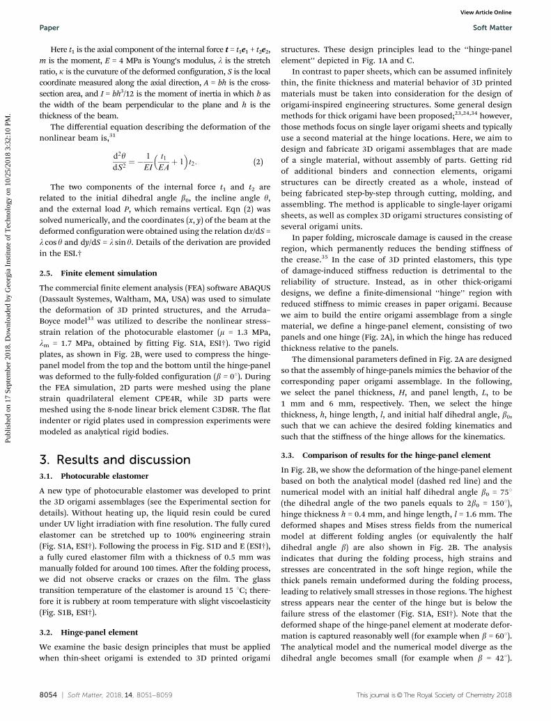
This discrepancy arises because the linear elastic model mightnot be accurate enough to describe the mechanics at largestrain.
Next, we examine how foldability is affected by changes inthe initial half dihedral angle b0, the hinge length l, and thehinge thickness h. First, h is varied while b0 and l are heldconstant (751 and 1.6 mm, respectively). In Fig. 2C, the appliedload P is plotted as a function of the vertical displacement atthe endpoint B. Here the load is measured per unit widthvertical to the paper, and thus the unit of load is N mm�1.Both the analytical results and the simulated results from FEAare nonlinear. As the hinge-panel element is folded (P Z 0), thestiffness of the hinge-panel element decreases. On the contrary,unfolding (P r 0) the hinge-panel element results in anincrease of stiffness, because the element is gradually deformedto the flat shape. As the thickness in the hinge region is reduced(from 900 mm to 400 mm), the slope of the load–displacementcurve decreases significantly, indicating an apparent reductionof the folding stiffness. From the results in Fig. 2C, for a flat1 mm thick panel, reducing the thickness of hinge to 400 mmcreates a soft and foldable hinge-panel element.
Subsequently, the thickness of the hinge is held at 400 mmand the length l and the initial dihedral angle b0 of the hingeare varied in a wide range (from 0 mm to 3 mm, and from 401 to901, respectively) to obtain the corresponding load–displacementcurves by using the NB model. We define the initial slope of theload–displacement curve as the stiffness, which is plotted as afunction of length and initial dihedral angle in Fig. 2D. Here theload is also measured per unit width, and the unit of stiffness isN mm�2. As the value of b0 approaches 901, the component ofthe load P that is perpendicular to the axes of the beam isreduced, causing a significant increase in stiffness. Decreasingthe length l of the hinge also results in a stiffer hinge-panelelement because it suppresses the rotational deformation atendpoint B, which contributes significantly to the rigid bodydeformation of the flat panel.
The results in Fig. 2C and D can be summarized as follows:if the thickness h of the hinge is properly reduced, the hinge-panel element only becomes stiff when the initial dihedralangle b0 is large and the hinge length l is small. Otherwise,changing b0 and l in a wide range (the deep blue color inFig. 2D) does not have a significant impact on the stiffness ofthe hinge-panel.
3.4. Additional design requirements
In addition to stiffness, additional physical requirements needto be considered in designing the hinge-panels. Although theanalytical and numerical results indicate that reduced thicknessin the hinge region is necessary for reduced stiffness, a finitethickness that depends on the resolution of the DLP 3D printer(typically 50 mm and above) and the stability of the part duringprinting,28 is required. If the thickness is too small, the strengthof hinge may not be enough to support the whole structure.In our experiments, the thickness of hinge was chosen to be400 mm, which can ensure printability and foldability at the sametime. Printability of the origami structure also influences the
choice of the initial half dihedral angle b0. In the as-printedstructures, collapse between adjacent panels should beavoided. During the folding and unfolding process (Fig. 1A),collapse appears in the two extreme conditions as the angle gchanges from 01 to a (while the half dihedral angle b0 changesfrom 901 to 01). As a result, although reducing the halfdihedral angle results in reduced hinge stiffness, an inter-mediate value of 751 (marked by the red star in Fig. 1A) waschosen in our experiments. Additionally, as shown in Fig. 1C-I,if two flat panels connected by a soft hinge are folded together,the length of the hinge must be large enough to accommodatethe thickness of panels. Assuming the hinge deforms into ahalf-circle, the length of the hinge (2l) should be more thanpH/2. Following the same discussion, if four flat panels con-nected by two soft hinges are folded together (Fig. 1C-II), thelength (2l) of the hinge should be more than pH. Finally, animportant design consideration is that a hole should be left atthe intersection of adjacent hinges to reduce stress concentra-tions during folding.
3.5. Design and manufacture of the Miura-ori sheet
As a simple example, we design and manufacture the classicalMiura-ori sheet in Fig. 3. The flat panels are printed with auniform thickness of 1 mm. The ‘mountain’ and ‘valley’creases1 of the Miura-ori sheet are composed of hingeswith a finite length (0.8 mm) and thickness (400 mm accordingto the previous discussion). The initial dihedral angleis 751, which ensures foldability. The length of the hinge isdetermined according to foldability and geometrical compat-ibility requirements. Assuming the deformed shape of thehinge to be an arc, the length of the hinge is related to thethickness of panels according to 2l = pH/2. Different foldingconfigurations of the printed Miura-ori sheet are shown inFig. 3B and C. The as-printed sheet can be either folded to thehighly compact shape (Fig. 3B), or opened to the flat shape(Fig. 3C).
Fig. 3 (A) The as-printed configuration of the Miura-ori sheet. (B) Thecompact folded configuration of the Miura-ori sheet. (C) The nearly-flatconfiguration of the Miura-ori sheet. (Scale bar: 5 mm).
Soft Matter Paper
Publ
ishe
d on
17
Sept
embe
r 20
18. D
ownl
oade
d by
Geo
rgia
Ins
titut
e of
Tec
hnol
ogy
on 1
0/25
/201
8 3:
32:1
0 PM
. View Article Online

8056 | Soft Matter, 2018, 14, 8051--8059 This journal is©The Royal Society of Chemistry 2018
3.6. Design and manufacture of the zipper-coupled tube unitcell
Here we are interested in the origami tube unit cell shown inFig. 1A. Similar to the analysis of a single hinge, the length ofthe crease on each edge of the origami tube is extended andthinned to reduce the stiffness. As shown in Fig. 1C-II, if theidea of the hinge-panel element is extended to 3D origamiassemblages, there will be many interconnections of hinges.In order to fold two adjacent hinge-panel elements at the sametime, the length of the hinge should be related to the thicknessof panels according to l = pH/2. During folding of an origamitube (Fig. 1A), the angle g increases from 01 to a (which is theoblique angle of the flat panel), while the dihedral angle bdecreases from 901 to 01. In our design, an intermediate valueof g = 451 was chosen for the as-printed origami tube, andb is related to g by means of the trigonometric relationcos b = tan g/tan a. This choice facilitates the printing process,and the dihedral angles of different hinges on the tube will notbe too large, which can fulfill the requirement of hinge stiffness(Fig. 2D).
The CAD model of two origami tubes zipper-coupledtogether is shown in Fig. 4A with finite-dimensional hingesand voids at the intersections of the hinges to facilitate thefolding process.25 The connection faces of the two tubes werecut by half and assembled with each other. As a result, theconnection panel between the two tubes possesses the samethickness relative to other panels. The process is shownschematically in Fig. S2 (ESI†). Several 3D printed samples withdistinct hinge thicknesses are illustrated in Fig. 4A.
The mechanical properties of the samples were testedby compressing along the central axes of tubes (Fig. 4B).
The nonlinear load–displacement relation, similar to that of asingle hinge (Fig. 4C), was captured by the FEA simulation.Details of the folding process from the FEA simulation areshown in Fig. 4D. Throughout the folding from the as-printedconfiguration to the flat configuration, most of the stress isconcentrated in the soft hinges. Stresses on the thick flat panelare trivial, and the panel maintains its initial shape throughoutthe deformation. In addition, the maximum stress in thestructure is well below the maximum stress of the material(which is around 4 MPa, Fig. S1A, ESI†).
3.7. Design and manufacture of the large-scale origamiassemblages
Next, we apply the design principles to large-scale origamiassemblages. As illustrated in Fig. 1C, separate origami tubescan be assembled together in two different manners. In the firstcase, tubes are assembled along the same direction, andadjacent faces coincide to form ‘aligned origami tubes’.In the second case, one set of the tubes is rotated by 1801,and adjacent tubes are assembled in a zig-zag manner, to formthe aforementioned ‘zipper-coupled origami tubes’.20 It isnoted that in paper origami, these two sets of origami tubesare fabricated separately then glued together; in our DLP 3Dprinting approach, the assemblages are printed directly withoutan assembling process, which is a significant advantage ofusing 3D printing to create origami structures.
A design procedure similar to that for coupling two origamitubes is used to create large-scale origami assemblages. Twotypes of 3D printed assemblages are shown in Fig. 5. Each ofthe assemblages consists of 9 tubes, and each tube consists of4 sections. The coordinate system of the assemblages is defined
Fig. 4 (A) 3D printed zipper-coupled origami tubes with different hinge thicknesses. (Scale bar: 5 mm; the CAD model is inserted to the right). (B)Experimental setup for the compression of the origami tubes. (C) Load–displacement curves of the zipper coupled origami tubes under compression. (D)FEA simulation of the folding process of the zipper-coupled origami tubes.
Paper Soft Matter
Publ
ishe
d on
17
Sept
embe
r 20
18. D
ownl
oade
d by
Geo
rgia
Ins
titut
e of
Tec
hnol
ogy
on 1
0/25
/201
8 3:
32:1
0 PM
. View Article Online
This journal is©The Royal Society of Chemistry 2018 Soft Matter, 2018, 14, 8051--8059 | 8057
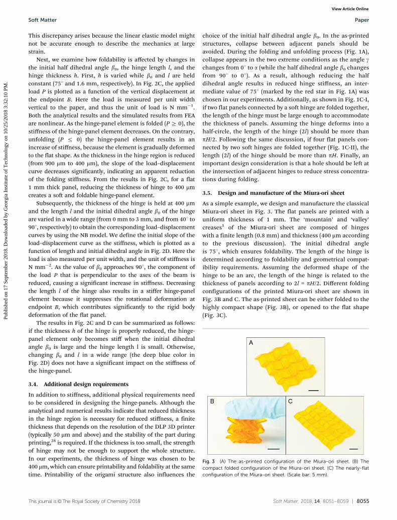
on the green cubes in Fig. 5. The two as-printed origamiassemblages (Fig. 5A and B) created by the two respectivemethods can be folded into different configurations. Whencompressed along the X-direction or the Y-direction, which aresymmetrical, the aligned origami tube assemblage is foldedinto a flat sheet (Fig. 5C). However, a more compact con-figuration is realized by folding the assemblage along theZ-direction (Fig. 5E). The zipper-coupled origami tube assemblagecan only be folded by compression along X-direction (Fig. 5D) orthe Z-direction (Fig. 5F), the foldability along the Y-direction isrestricted by the obstruction between adjacent tubes. The foldingprocess of these two structures is shown in Movie S1 (ESI†).It should be noted that compared with folded aligned origamitubes, the folded zipper-coupled origami tubes are more compact,which is beneficial for use as expandable structures.
A major advantage of zipper-coupled origami tubes is theability to achieve foldability and load-carrying capability at thesame time. Origami bridges fabricated using two types ofassembly methods are shown in Fig. 6. Six origami tubes arealigned in parallel to create the bridge in Fig. 6A, and sixorigami tubes are zipper-coupled to create the bridge inFig. 6B. When a dead weight of 200 g (which is almost 100 timesthe weight of the bridge) is put on the top face of the bridge, thealigned origami bridge collapses and folds towards the flatconfiguration (Fig. 6C and Movie S2, ESI†). However, thezipper-coupled bridge can hold the dead weight and maintain
its shape under the load (Fig. 6D) because, similarly to theresults in Fig. 5, the foldability of zipper-coupled origami tubesalong the vertical direction is restricted by the obstructionbetween adjacent tubes.
The load-bearing capacity of the zipper-coupled bridgewas further confirmed using an FEA simulation. The alignedorigami bridge collapsed under compression, as the loadingdirection coincides with the direction of folding. Under thesame compression load, the zipper-coupled bridge only exhibitedlocal stress concentrations (Fig. 6E and F).
In addition to the cellular origami assemblages displayedabove, origami tubes can also be assembled into other complexstructures. In previous work, many of these structures couldonly be realized through the folding and gluing of papers.20,36
In Fig. 7A–D, the six-sided polygonal tubes are assembledwith the four-sided quadrilateral tubes. The assembled crosssections are shown on the top of Fig. 7A and C. Two types ofassemblages are realized by adjusting the oblique of the tubesalong the two different symmetry axes. Due to the geometricalrestriction of the hexagon tubes, the square-hexagon coupledassemblage only has one possible folded configuration. Theorigami assemblage inclined along the long axes of the cross-section could be folded to a flat sheet (Fig. 7A and B), while theorigami assemblage inclined along the short axes is folded to aslim shape (Fig. 7C and D). The folding process of the structuresin Fig. 7A and C is shown in Movie S3 (ESI†). Fig. 7E and F show
Fig. 5 (A) The as-printed configuration of aligned origami tubes. (B) Theas-printed configuration of zipper-coupled origami tubes. (C) Foldedconfiguration of the aligned origami tubes (along direction X or Y). (D)Folded configuration of the zipper-coupled origami tubes (along directionX). (E) Folded configuration of the aligned origami tubes (along direction Z).(F) Folded configuration of the zipper-coupled origami tubes (alongdirection Z). (Scale bar: 5 mm).
Fig. 6 (A) The as-printed configuration of the ‘‘aligned origami’’ bridge. (B)The as-printed configuration of the ‘‘zipper-coupled origami’’ bridge. (C)The deformed shape of the aligned origami bridge under dead weight. (D)The deformed shape of the zipper-coupled origami bridge under deadweight. (E) FEA simulations of the origami bridges under compression. (F)Load–displacement curves of the origami bridges under compression.(Scale bar: 5 mm; dead weight: 200 g; the weight of the bridge: 2 g).
Soft Matter Paper
Publ
ishe
d on
17
Sept
embe
r 20
18. D
ownl
oade
d by
Geo
rgia
Ins
titut
e of
Tec
hnol
ogy
on 1
0/25
/201
8 3:
32:1
0 PM
. View Article Online

8058 | Soft Matter, 2018, 14, 8051--8059 This journal is©The Royal Society of Chemistry 2018
an example of an adjustable profile curvature in 3D origamiassemblages. In Fig. 7E, the square origami tubes are one-by-onezipper assembled to a ‘C’ shape, with two sharp corners. As wefold the assemblage from the top, the zipper-coupled tubescontract together and the profile became a smooth ‘C’ shape.The sharp corners are hidden inside the folded panels.
4. Conclusion
In this paper, we propose a new method to directly fabricate 3Dorigami assemblages out of a single polymeric material usingDLP 3D printing technology, without the need to assemblemultiple parts. In order to construct origami-inspired struc-tures out of engineering materials, we introduce a hinge-panelelement consisting of thick panels and reduced-thicknesshinge regions with finite length and thickness. Design para-meters of the hinge-panel element, including the thickness, thelength, and the dihedral angle, are investigated theoreticallyand experimentally. By decreasing the thickness of hinges,significant stiffness reduction is created, and folding behaviorsimilar to folding paper is realized. The hinge-panel element isapplied to print different 3D origami assemblages that had onlybeen fabricated using paper previously. A novel elastomersystem that is photocurable and printable at room temperatureis proposed, which ensures the mechanical reliability of 3D
printed origami structures. Spatial expandability, load-bearingcapacity, and curvature transformation are realized using ourgeometrical design and assembly methods. This work providesan exploration into the implementation of origami art byengineering materials to engineering structures. The designprinciples proposed in this work can potentially be extended toother material systems and fabrication methods.
Conflicts of interest
There are no conflicts to declare.
Acknowledgements
We gratefully acknowledge support from an AFOSR grant(FA9550-16-1-0169; Dr B.-L. ‘‘Les’’ Lee, Program Manager); fromNSF awards CMMI-1462894, CMMI-1462895, and CMMI-1538830;and from a gift fund from HP. In addition, ZZ, QZ and DFacknowledge support from the National Natural Science Founda-tion of China (11521202) and from the National Materials Gen-ome Project of China (2016YFB0700600). ZZ also acknowledgessupport from China Scholarship Council No. 201506010219. GHPacknowledges support from the Raymond Allen Jones Chair at theGeorgia Institute of Technology. We appreciate the useful com-ments provided by Emily D. Sanders.
References
1 Z. Y. Wei, Z. V. Guo, L. Dudte, H. Y. Liang andL. Mahadevan, Geometric Mechanics of Periodic PleatedOrigami, Phys. Rev. Lett., 2013, 110(21), 215501.
2 M. Schenk and S. D. Guest, Geometry of Miura-foldedmetamaterials, Proc. Natl. Acad. Sci. U. S. A., 2013, 110(9),3276–3281.
3 E. Boatti, N. Vasios and K. Bertoldi, Origami Metamaterialsfor Tunable Thermal Expansion, Adv. Mater., 2017, 29(26),1700360.
4 J. L. Silverberg, A. A. Evans, L. McLeod, R. C. Hayward,T. Hull, C. D. Santangelo and I. Cohen, Using origamidesign principles to fold reprogrammable mechanical meta-materials, Science, 2014, 345(6197), 647–650.
5 L. H. Dudte, E. Vouga, T. Tachi and L. Mahadevan,Programming curvature using origami tessellations,Nat. Mater., 2016, 15(5), 583–588.
6 B. G. G. Chen, B. Liu, A. A. Evans, J. Paulose, I. Cohen,V. Vitelli and C. D. Santangelo, Topological Mechanics ofOrigami and Kirigami, Phys. Rev. Lett., 2016, 116(13), 135501.
7 S. Felton, M. Tolley, E. Demaine, D. Rus and R. Wood, Amethod for building self-folding machines, Science, 2014,345(6197), 644–646.
8 Y. H. Zhang, F. Zhang, Z. Yan, Q. Ma, X. L. Li, Y. G. Huangand J. A. Rogers, Printing, folding and assembly methodsfor forming 3D mesostructures in advanced materials,Nat. Rev. Mater., 2017, 2(5), 17019.
Fig. 7 (A) The as-printed configuration of the mode I square-hexagoncoupled assemblage. (B) The deformed shape of the mode I square-hexagon coupled assemblage. (C) The as-printed configuration of themode II square-hexagon coupled assemblage. (D) The deformed shape ofthe mode II square-hexagon coupled assemblage. (E) The as-printedconfiguration of the ‘C’ shape origami assemblage. (F) The deformedshape of the ‘C’ shape origami assemblage. (Scale bar: 5 mm).
Paper Soft Matter
Publ
ishe
d on
17
Sept
embe
r 20
18. D
ownl
oade
d by
Geo
rgia
Ins
titut
e of
Tec
hnol
ogy
on 1
0/25
/201
8 3:
32:1
0 PM
. View Article Online

This journal is©The Royal Society of Chemistry 2018 Soft Matter, 2018, 14, 8051--8059 | 8059
9 Z. M. Song, T. Ma, R. Tang, Q. Cheng, X. Wang,D. Krishnaraju, R. Panat, C. K. Chan, H. Y. Yu andH. Q. Jiang, Origami lithium-ion batteries, Nat. Commun.,2014, 5, 3140.
10 Z. Wang, L. Jing, K. Yao, Y. Yang, B. Zheng, C. M. Soukoulis,H. Chen and Y. Liu, Origami-Based Reconfigurable Meta-materials for Tunable Chirality, Adv. Mater., 2017, 29(27),1700412.
11 S. Babaee, J. T. B. Overvelde, E. R. Chen, V. Tournat andK. Bertoldi, Reconfigurable origami-inspired acoustic wave-guides, Sci. Adv., 2016, 2(11), e1601019.
12 W. Wang, C. Li, H. Rodrigue, F. P. Yuan, M. W. Han, M. Choand S. H. Ahn, Kirigami/Origami-Based Soft DeployableReflector for Optical Beam Steering, Adv. Funct. Mater.,2017, 27(7), 1604214.
13 X. Zhou, S. X. Zang and Z. You, Origami mechanicalmetamaterials based on the Miura-derivative fold patterns,Proc. R. Soc. A, 2016, 472(2191), 20160361.
14 J. M. Gattas and Z. You, Geometric assembly of rigid-foldable morphing sandwich structures, Eng. Struct., 2015,94, 149–159.
15 N. Yang and J. L. Silverberg, Decoupling local mechanicsfrom large-scale structure in modular metamaterials, Proc.Natl. Acad. Sci. U. S. A., 2017, 114(14), 3590–3595.
16 K. C. Cheung, T. Tachi, S. Calisch and K. Miura, Origamiinterleaved tube cellular materials, Smart Mater. Struct.,2014, 23(9), 094012.
17 T. Tachi and K. Miura, Rigid-foldable cylinders and cells,J. Int. Assoc. Shell Spat. Struct., 2012, 53, 217–226.
18 E. T. Filipov, T. Tachi and G. H. Paulino, Origami tubesassembled into stiff, yet reconfigurable structures andmetamaterials, Proc. Natl. Acad. Sci. U. S. A., 2015, 112(40),12321–12326.
19 S. Li, H. Fang and K. W. Wang, Recoverable and ProgrammableCollapse from Folding Pressurized Origami Cellular Solids,Phys. Rev. Lett., 2016, 117(11), 114301.
20 E. T. Filipov, G. H. Paulino and T. Tachi, Origami tubes withreconfigurable polygonal cross-sections, Proc. R. Soc. A,2016, 472(2185), 20150607.
21 H. Yasuda and J. Yang, Reentrant Origami-Based Metama-terials with Negative Poisson’s Ratio and Bistability, Phys.Rev. Lett., 2015, 114(18), 185502.
22 J. T. B. Overvelde, J. C. Weaver, C. Hoberman andK. Bertoldi, Rational design of reconfigurable prismaticarchitected materials, Nature, 2017, 541(7637), 347–352.
23 Y. Chen, R. Peng and Z. You, Origami of thick panels,Science, 2015, 349(6246), 396–400.
24 S. A. Zirbel, R. J. Lang, M. W. Thomson, D. A. Sigel,P. E. Walkemeyer, B. P. Trease, S. P. Magleby andL. L. Howell, Accommodating Thickness in Origami-BasedDeployable Arrays, J. Mech. Design, 2013, 135(11), 111005.
25 Z. Zhao, J. Wu, X. Mu, H. Chen, H. J. Qi and D. Fang,Origami by frontal photopolymerization, Sci. Adv., 2017,3, e1602326.
26 T. van Manen, S. Janbaz and A. A. Zadpoor, Programming2D/3D shape-shifting with hobbyist 3D printers, Mater.Horiz., 2017, 4(6), 1064–1069.
27 R. L. Truby and J. A. Lewis, Printing soft matter in threedimensions, Nature, 2016, 540(7633), 371–378.
28 J. R. Tumbleston, D. Shirvanyants, N. Ermoshkin, R. Janusziewicz,A. R. Johnson, D. Kelly, K. Chen, R. Pinschmidt, J. P. Rolland,A. Ermoshkin, E. T. Samulski and J. M. DeSimone, Continuousliquid interface production of 3D objects, Science, 2015, 347(6228),1349–1352.
29 X. Y. Zheng, H. Lee, T. H. Weisgraber, M. Shusteff, J. DeOtte,E. B. Duoss, J. D. Kuntz, M. M. Biener, Q. Ge, J. A. Jackson,S. O. Kucheyev, N. X. Fang and C. M. Spadaccini, Ultralight,Ultrastiff Mechanical Metamaterials, Science, 2014,344(6190), 1373–1377.
30 Z. Ding, C. Yuan, X. Peng, T. Wang, H. J. Qi and M. L. Dunn,Direct 4D printing via active composite materials, Sci. Adv.,2017, 3, e1602890.
31 Z. Fan, Y. Zhang, Q. Ma, F. Zhang, H. Fu, K. C. Hwang andY. Huang, A finite deformation model of planar serpentineinterconnects for stretchable electronics, Int. J. SolidsStruct., 2016, 91, 46–54.
32 Y. W. Su, J. Wu, Z. C. Fan, K. C. Hwang, J. Z. Song,Y. G. Huang and J. A. Rogers, Postbuckling analysis andits application to stretchable electronics, J. Mech. Phys.Solids, 2012, 60(3), 487–508.
33 E. M. Arruda and M. C. Boyce, A three-dimensional consti-tutive model for the large stretch behavior of rubber elasticmaterials, J. Mech. Phys. Solids, 1993, 41(2), 389–412.
34 R. J. Lang, K. A. Tolman, E. B. Crampton, S. P. Magleby andL. L. Howell, A Review of Thickness-Accommodation Tech-niques in Origami-Inspired Engineering, Appl. Mech. Rev.,2018, 70(1), 010805.
35 A. Giampieri, U. Perego and R. Borsari, A constitutive modelfor the mechanical response of the folding of creased paper-board, Int. J. Solids Struct., 2011, 48(16–17), 2275–2287.
36 E. T. Filipov, K. Liu, T. Tachi, M. Schenk and G. H. Paulino,Bar and hinge models for scalable analysis of origami,Int. J. Solids Struct., 2017, 124, 26–45.
Soft Matter Paper
Publ
ishe
d on
17
Sept
embe
r 20
18. D
ownl
oade
d by
Geo
rgia
Ins
titut
e of
Tec
hnol
ogy
on 1
0/25
/201
8 3:
32:1
0 PM
. View Article Online