3D printed chitosan/polycaprolactone scaffold for lung ...
13
3D printed chitosan/polycaprolactone scaffold for lung tissue engineering: hope to be useful for COVID-19 studies Farnoush Sadat Rezaei, ae Ayeh Khorshidian, be Farzaneh Mahmoudi Beram, ce Atefeh Derakhshani, de Javad Esmaeili * ef and Aboulfazl Barati f To prevent or reduce mortality from lung diseases, new biological materials and scaffolds are needed to conduct more accurate research and support lung tissue regeneration. On the other hand, the outbreak of the COVID-19 virus and its targeting of the human lung has caused many deaths worldwide. The main aim of this study was to provide a biologically and mechanically suitable 3D printed scaffold using chitosan/polycaprolactone bioink for lung tissue engineering. Design-Expert software was employed for studying various compositions for 3D printing. The selected scaffolds underwent physiochemical, biological and mechanical studies to evaluate if they are capable of MRC-5 cell line growth, proliferation, and migration. Based on the results, the average diameter of the chitosan/polycaprolactone strands was measured at 360 mm. Chitosan concentration controlled the printability, while changes in polycaprolactone content did not affect printability. The scaffolds showed excellent potential in swelling, degradation, and mechanical behavior, although they can be modified by adjusting the polycaprolactone content. The scaffolds also revealed notable cell adhesion, nontoxicity, low apoptosis, high proliferation, and cell biocompatibility in vitro. To sum up, scaffold 3 (chitosan/polycaprolactone ratio: 4 : 1) revealed better activity for MRC-5 cell culture. Thereby, this scaffold can be a good candidate for lung tissue engineering and may be applicable for more studies on the COVID-19 virus. 1. Introduction Lung disease is known as a leading cause of malady and mortality in the world. Chronic obstructive pulmonary disease (COPD), pulmonary hypertension (PH), cystic brosis (CF), lung cancer, and specically lung infection via coronavirus are well- known lung diseases. Currently, the only treatment with posi- tive results is a lung transplant; however, organ transplants are hampered by the shortage of donors worldwide, the need for lifelong immune suppression, and limited success. Tissue engineering (TE) is a promising eld for treating lung defects resulting from external damage or disease. 1 Porous scaffolds are a mimic support template for tissue and cell growth. 2 Tissue engineering and regenerative medicine using biomaterials have recently developed new technologies applicable to boost lung studies. 3 A comprehensive review was carried out by Akter et al. 4 Natural biomaterials are widely employed in TE because of their inherent bioactivity and microstructure interconnectivity, which mimics the extracellular matrix (ECM), cell adhesion, providing cell inltration and differentiation, oxygen and nutrient transportation, and eventually retrieval of the function and structure of imperfective tissues or organs. 5 Chitosan (CS) is biorenewable, biodegradable, biocompat- ible, and biofunctional, and is extensively employed in TE. 6 The potential of CS as a biological substance is due to its cationic nature and its high charge density in solution. 7 There are many reactive amino and carboxyl groups on CS molecules that can be chemically modied by introducing new functional groups. 8 The N-acetylglucosamine moiety in CS is structurally similar to glycosaminoglycan (GAGs), which has specic interactions with growth factors, receptors, and adhesion proteins. Thus, the analogous structure in CS may also have the same bioactivity. 9 All biopolymers have positive and negative properties in 3D printing (3DP). CS molecular weight and feed ratio affect the precision and shape of the structure. If low molecular weight CS is employed, then to neutralize the protonated amino groups, a higher concentration of sodium acetate is required. 10 Considering the 3DP technique, reduction in the diameter of the strands results in weak mechanical properties. CS has poor a Department of Chemical Engineering, Faculty of Engineering, Amir Kabir University, Tehran, Iran b Department of Biology, Faculty of Basic Sciences, Gonbad Kavous University, Gonbad Kavous, Golestan, Iran c Department of Chemistry, Faculty of Chemistry, Isfahan University, Isfahan, Iran d Department of Nanotechnology & Advanced Material, Materials and Energy Research Center (MERC), Karaj, Iran e Department of Tissue Engineering, TISSUEHUB Co., Tehran, Iran. E-mail: [email protected] f Department of Chemical Engineering, Faculty of Engineering, Arak University, Arak, Iran Cite this: RSC Adv. , 2021, 11, 19508 Received 30th April 2021 Accepted 11th May 2021 DOI: 10.1039/d1ra03410c rsc.li/rsc-advances 19508 | RSC Adv., 2021, 11, 19508–19520 © 2021 The Author(s). Published by the Royal Society of Chemistry RSC Advances PAPER Open Access Article. Published on 28 May 2021. Downloaded on 11/30/2021 3:07:34 AM. This article is licensed under a Creative Commons Attribution 3.0 Unported Licence. View Article Online View Journal | View Issue
Transcript of 3D printed chitosan/polycaprolactone scaffold for lung ...

RSC Advances
PAPER
Ope
n A
cces
s A
rtic
le. P
ublis
hed
on 2
8 M
ay 2
021.
Dow
nloa
ded
on 1
1/30
/202
1 3:
07:3
4 A
M.
Thi
s ar
ticle
is li
cens
ed u
nder
a C
reat
ive
Com
mon
s A
ttrib
utio
n 3.
0 U
npor
ted
Lic
ence
.
View Article OnlineView Journal | View Issue
3D printed chito
aDepartment of Chemical Engineering, Facu
Tehran, IranbDepartment of Biology, Faculty of Basic Scie
Kavous, Golestan, IrancDepartment of Chemistry, Faculty of ChemidDepartment of Nanotechnology & Advanced
Center (MERC), Karaj, IraneDepartment of Tissue Engineering, TIS
[email protected] of Chemical Engineering, Facu
Iran
Cite this: RSC Adv., 2021, 11, 19508
Received 30th April 2021Accepted 11th May 2021
DOI: 10.1039/d1ra03410c
rsc.li/rsc-advances
19508 | RSC Adv., 2021, 11, 19508–19
san/polycaprolactone scaffold forlung tissue engineering: hope to be useful forCOVID-19 studies
Farnoush Sadat Rezaei,ae Ayeh Khorshidian,be Farzaneh Mahmoudi Beram,ce
Atefeh Derakhshani,de Javad Esmaeili *ef and Aboulfazl Baratif
To prevent or reduce mortality from lung diseases, new biological materials and scaffolds are needed to
conduct more accurate research and support lung tissue regeneration. On the other hand, the outbreak
of the COVID-19 virus and its targeting of the human lung has caused many deaths worldwide. The main
aim of this study was to provide a biologically and mechanically suitable 3D printed scaffold using
chitosan/polycaprolactone bioink for lung tissue engineering. Design-Expert software was employed for
studying various compositions for 3D printing. The selected scaffolds underwent physiochemical,
biological and mechanical studies to evaluate if they are capable of MRC-5 cell line growth, proliferation,
and migration. Based on the results, the average diameter of the chitosan/polycaprolactone strands was
measured at 360 mm. Chitosan concentration controlled the printability, while changes in
polycaprolactone content did not affect printability. The scaffolds showed excellent potential in swelling,
degradation, and mechanical behavior, although they can be modified by adjusting the polycaprolactone
content. The scaffolds also revealed notable cell adhesion, nontoxicity, low apoptosis, high proliferation,
and cell biocompatibility in vitro. To sum up, scaffold 3 (chitosan/polycaprolactone ratio: 4 : 1) revealed
better activity for MRC-5 cell culture. Thereby, this scaffold can be a good candidate for lung tissue
engineering and may be applicable for more studies on the COVID-19 virus.
1. Introduction
Lung disease is known as a leading cause of malady andmortality in the world. Chronic obstructive pulmonary disease(COPD), pulmonary hypertension (PH), cystic brosis (CF), lungcancer, and specically lung infection via coronavirus are well-known lung diseases. Currently, the only treatment with posi-tive results is a lung transplant; however, organ transplants arehampered by the shortage of donors worldwide, the need forlifelong immune suppression, and limited success. Tissueengineering (TE) is a promising eld for treating lung defectsresulting from external damage or disease.1 Porous scaffolds area mimic support template for tissue and cell growth.2 Tissueengineering and regenerative medicine using biomaterials have
lty of Engineering, Amir Kabir University,
nces, Gonbad Kavous University, Gonbad
stry, Isfahan University, Isfahan, Iran
Material, Materials and Energy Research
SUEHUB Co., Tehran, Iran. E-mail:
lty of Engineering, Arak University, Arak,
520
recently developed new technologies applicable to boost lungstudies.3 A comprehensive review was carried out by Akter et al.4
Natural biomaterials are widely employed in TE because oftheir inherent bioactivity and microstructure interconnectivity,which mimics the extracellular matrix (ECM), cell adhesion,providing cell inltration and differentiation, oxygen andnutrient transportation, and eventually retrieval of the functionand structure of imperfective tissues or organs.5
Chitosan (CS) is biorenewable, biodegradable, biocompat-ible, and biofunctional, and is extensively employed in TE.6 Thepotential of CS as a biological substance is due to its cationicnature and its high charge density in solution.7 There are manyreactive amino and carboxyl groups on CSmolecules that can bechemically modied by introducing new functional groups.8
The N-acetylglucosamine moiety in CS is structurally similar toglycosaminoglycan (GAGs), which has specic interactions withgrowth factors, receptors, and adhesion proteins. Thus, theanalogous structure in CS may also have the same bioactivity.9
All biopolymers have positive and negative properties in 3Dprinting (3DP). CS molecular weight and feed ratio affect theprecision and shape of the structure. If lowmolecular weight CSis employed, then to neutralize the protonated amino groups,a higher concentration of sodium acetate is required.10
Considering the 3DP technique, reduction in the diameter ofthe strands results in weak mechanical properties. CS has poor
© 2021 The Author(s). Published by the Royal Society of Chemistry
Table 1 Experimental design parameters and responses
Run Factor 1 A: chit.%Factor 2 B:PCL% Chit.% PCL% Printability
1 0 0 2 2.5 22 0 0 2 2.5 23 1 �1 4 1 34 �1 1 0 4 15 1 1 4 4 36 0 0 2 2.5 27 0 �1 2 1 18 �1 �1 0 1 19 0 0 2 2.5 210 �1 0 0 2.5 211 0 1 2 4 212 1 0 4 2.5 313 0 0 2 2.5 2
Paper RSC Advances
Ope
n A
cces
s A
rtic
le. P
ublis
hed
on 2
8 M
ay 2
021.
Dow
nloa
ded
on 1
1/30
/202
1 3:
07:3
4 A
M.
Thi
s ar
ticle
is li
cens
ed u
nder
a C
reat
ive
Com
mon
s A
ttrib
utio
n 3.
0 U
npor
ted
Lic
ence
.View Article Online
mechanical properties which in the case of 3DP can be a majorproblem. Thereby, it is recommended to combine it with otherbiopolymers. Based on the targeted tissue (so or hard tissue),to improve biological, osteoconductivity, and mechanicalproperties of chitosan, it is suggested to blend it with othermaterials such as bioglass,11 collagen,12 etc. The desired prop-erties for the fabricated scaffold and also the features of thetargeted tissue or organ (e.g., being hard or so) need to beconsidered to choose the best materials.
Polycaprolactone (PCL) is a commonly used polymer in TEapplications due to its strong mechanical properties andbiodegradability.13 PCL is one of the main available biomate-rials that provide a tensile strength in hydrogels and scaffoldsunder the crosslinking process to design appropriateconstructs. So, scaffolds containing PCL have received perfectacceptance in clinical studies.14 There are several studiesconsidering blends of CS and PCL for TE purposes.15 In researchby Semnani et al.,7 a CS/PCL blend was used to fabricate anelectrospun scaffold for liver TE. The made scaffold revealedgood mechanical properties, hydrophilicity, cell attachment,and cell growth. In another research study, scientists provedthat a CS/PCL composition can be a good candidate for TE.16
Considering skin TE, a CS/PCL scaffold showed its viabilityagainst HSF 1184 (human skin broblast cells).17 In the case ofbone TE, a CS/PCL freeze-dried scaffold revealed its highpotential in cell viability due to having homogeneous porosityand improved hydrophilic properties.
According to the previous studies, it can be concluded thatthe CS/PCL scaffold, depending on the CS : PCL ratio, can beused for both hard and so tissues. Enhancement in the CScontent makes the scaffold suitable for so tissues, whileincreasing the PCL content makes it eligible for hard tissues.Thereby, it is hypothesized that this blend can also be nomi-nated for lung TE. Hence, the main aim of this study was todesign a new 3D printed CS/PCL scaffold capable of supportingand transporting Medical Research Council cell strain 5 (MRC-5) developed from the lung tissue for lung TE. To this aim,various CS : PCL ratios were selected according to DOE so-ware. Creating such a scaffold would be benecial for COVID-19-based studies regarding preclinical trials for drugs orvaccines approval.
2. Materials and methods2.1. Materials
Chitosan (CS, Sigma-Aldrich Canada Ltd, with a molecularweight of 50 000–190 000 Da), polycaprolactone (PCL, 99%,Merck), acetic acid (100%, Merck), and chloroform (Merck) werepurchased from a local supplier, TemadKala Co., Tehran, Iran.All the materials and the reagents were of analytical grade.
2.2. Design expert (DOE)
In this study, response surface methodology (RSM) and centralcomposite design (CCD) were employed to nd the optimumformulation to prepare the 3D printed PCL/CS scaffold withproper strand diameter, appropriate tensile strength, and best
© 2021 The Author(s). Published by the Royal Society of Chemistry
cell compatibility. For each run, the main parameters (pressure(P), temperature (T), and velocity (V)) were adjusted. Accord-ingly, the percentage of PCL and CS in the bioink compositionwere considered as the process parameters in DOE. Three levels,including low (�1), medium (0), and high (+1), were dened forPCL and CS concentration. For PCL, the low and high levelswere 1% and 4% w/w, respectively, and for CS were 0% and 4%.According to Table 1, 13 runs were performed. The measuredresponse was transferred in the soware, which providedequations and relevant graphs to show the governing relation-ships between material composition and the consideredresponse. The main aim of DOE was to nd out the mostoptimal conditions and composition for making the scaffold.
2.3. Bioink preparation
According to the following method, polymer solutions wereprepared: rst, following the DOE report, the appropriateamount of PCL was dissolved in 3 ml of chloroform. Then, anappropriate percentage of CS was weighed and added. Next, thesolution wasmixed to obtain a uniform solution. Finally, 5 ml ofacetic acid (90% v/v) was added to the solution dropwise undersonication (170 W, 50 �C). Sonication was continued until allthe CS particles were dissolved, and a yellowish viscose solutionwas obtained. To remove the residual chloroform, the solutionwas put in a desiccator under vacuum conditions. The nalsolution was transferred to a test tube and kept in the refrig-erator until the printing process.
2.4. Viscosity
Viscosity of the CS/PCL solutions was determined usinga RheolabQC (C-LTD180/QC) viscosimeter. The measurementswere carried out at 22 �C with a shear rate of 15 s�1.
2.5. Scaffold fabrication
A 3D Bioplotter (3DPL, Iran) was employed to print scaffolds of10 � 10 � 5 mm3. All groups of hydrogels were deposited usinga 300 mm needle inner diameter. Magics13 EnvisionTEC so-ware and Bioplotter RP soware were used for the CAD model
RSC Adv., 2021, 11, 19508–19520 | 19509
RSC Advances Paper
Ope
n A
cces
s A
rtic
le. P
ublis
hed
on 2
8 M
ay 2
021.
Dow
nloa
ded
on 1
1/30
/202
1 3:
07:3
4 A
M.
Thi
s ar
ticle
is li
cens
ed u
nder
a C
reat
ive
Com
mon
s A
ttrib
utio
n 3.
0 U
npor
ted
Lic
ence
.View Article Online
generation and slicing, respectively. Scaffolds were fabricatedlayer-by-layer. Aer the scaffold fabrication, 0.5 ml calciumchloride (CaCl2 16%) was dispersed over the scaffold as thecrosslinker. The lament width, pore sizes, and pore area of theoptimum scaffold were measured using ImageJ® soware.Some formulations, due to different reasons, were not print-able. Each formulation possessed special conditions, includingtemperature (T), pressure (P), and velocity (V). To show thedistinct behavior of the prepared bioinks, three scores havebeen considered: if the bioink did not work for printing (score1), if the bioink was printable with adjusting operationparameters (score 2), easily printable (score 3). To check thefabricated scaffolds’ uniformity, at least three scaffolds wereprinted and evaluated in pore size and strand diameter.
2.6. Scanning electron microscopy
Tomeasure the size distribution and surface structure of the 3Dprinted scaffolds, and also cell attachment, scanning electronmicroscopy (SEM) (Philips XL30; Philips, Eindhoven, Nether-lands) was carried out under a 25 kV accelerated voltage aersputtering a gold layer with a 5 nm diameter on the samples.The average strand diameter was calculated using the ImageJsoware (National Institutes of Health, USA).
2.7. Swelling test
The primary weight of the hydrogel scaffolds was measuredaer removing them from the crosslinker solution. The scaf-folds were then incubated in 10 mM PBS solution in pH 7.4 at37 �C and 5% carbon dioxide (according to the cell cultureconditions). The samples’ weights were measured again aer 1day, 2 days, and 3 days for any mass change due to swelling. AKimwipe was used to eliminate excess or free liquid from thescaffolds before weighing each sample. The swelling of thecomposite scaffolds was calculated using the followingequation:
% swelling ¼ Wt �W0
W0
� 100 (1)
Wt is the hydrogel weight at the specic time, andW0 is the earlyweight of the scaffolds.
2.8. Degradation test
Scaffolds were freeze-dried and then weighed to determine theirinitial masses. The samples were incubated in 10 mM PBSsolution in pH¼ 7.4 at 37 �C and 5% carbon dioxide for 3, 7, 14,and 21 days to obtain the degraded scaffolds. The PBS solutionwas taken out of the samples and then washed with deionizedwater two times, and then the samples were freeze-dried andweighed again using a digital scale. The scaffold degradationwas calculated using the following equation:
% degradation ¼ W0 �Wt
W0
� 100 (2)
Wt is the freeze-dried scaffold weight at a given time, and W0 isthe freeze-dried scaffold weight at the time zero.
19510 | RSC Adv., 2021, 11, 19508–19520
2.9. Determination of porosity
The porosity of the CS–PCL scaffolds was measured by theliquid exchange method. Ethanol was chosen as the substituteliquid because it quickly penetrates the scaffold without dis-solving the scaffold or changing its structure. To perform thetest, the dry weight of the scaffold Wdry was measured rst, andthen the scaffold was immersed in ethanol for 5 minutes toobliterate air bubbles. Then the scaffold was removed andimmediately placed on lter paper so that the liquid on thescaffold’s surface is absorbed in the lter paper. Finally, theweight of the scaffold Wwet was recalculated. According to eqn(3), the porosity value is calculated for each scaffold:
V ¼ �Wwet �Wdry
�� 106 ml
789 000 g
¼ �Wwet �Wdry
�� 1:267 ml g�1 (3)
2.10. Tensile strength
The uniaxial tensile test was performed by a precision machinedesigned for this purpose. The samples remained in the sameposition for 20 seconds until they were rmly xed. Then a forceof about 0.02 N was applied to ensure that the specimens wereattached to the clamps. Then force was applied to the samplesto the point of rupture, and a stress–strain diagram was drawnfor them.
2.11. MTT assay
First, the scaffolds were immersed in 70% ethanol for 24 hours.Aer drying the scaffolds at room temperature, the scaffolds(both sides) were sterilized for one hour by exposure to UV rays.The scaffolds were then placed on a plate and washed withsterile PBS. MRC-5 cells (Medical Research Council cell strain 5is known as a diploid cell culture line which consists of bro-blasts, originally developed from the lung tissue) obtained fromthe cell bank in School of Advanced Technologies in Medicine(Shahid Beheshti University of Medical Sciences, Tehran, Iran)with a density of 2 � 105 per milliliter were placed on scaffoldsby the drip method at a rate of 20 microliters. Next, the scaffoldswere incubated for 48 h at 37 �C and 5% CO2. At the end of theperiod, 10 ml of the MTT labeling reagent at the concentration0.5 mg ml�1 was added to each well and incubated with themfor 4 h under the same conditions (37 �C and 5% CO2). Then,100 ml of the solubilization solution was added into each well.The plate was le for incubation at 37 �C and 5% CO2 overnight.The purple formazan crystals were checked and the absorbancewas measured using an ELISA reader.18
2.12. Cell attachment study
Cell attachment of MRC-5 cells on the scaffolds was studied48 h post-cell-seeding. The process was carried out according toa previous study.15 Briey, aer removing the supernatant of thescaffolds, the cell-laden scaffolds were gently rinsed using PBS(three times). Then the cultured MRC-5 cells were xed at roomtemperature for 1 h using glutaraldehyde (2.5% v/v). Aerward,
© 2021 The Author(s). Published by the Royal Society of Chemistry
Paper RSC Advances
Ope
n A
cces
s A
rtic
le. P
ublis
hed
on 2
8 M
ay 2
021.
Dow
nloa
ded
on 1
1/30
/202
1 3:
07:3
4 A
M.
Thi
s ar
ticle
is li
cens
ed u
nder
a C
reat
ive
Com
mon
s A
ttrib
utio
n 3.
0 U
npor
ted
Lic
ence
.View Article Online
glutaraldehyde as a xing solution was removed from the cell-seeded scaffolds which were rinsed slightly by PBS. The xa-tion process continued by sequential dehydration in variousconcentrations of ethanol (10%, 30%, 50%, 70%, 90%, and100%) and air-drying overnight. The samples were thenanalyzed by SEM.
2.13. DAPI staining
In this study, 4 � 104 cells were transferred to each of the sterileplates. Aer 24, 48 and 72 h, the cells were transferred fromsterile plates to scaffolds. Then, with 1% saline phosphatebuffer (PBS), they were placed in a volume of 1 ml for 10minutes; this was repeated two times. The scaffolds were thenplaced in 4% paraformaldehyde solution for 10 minutes andwashed again with PBS. In the next step, 0.1% Triton solutionwas used for 5 minutes. Then it was rewashed with PBS, andthen a few drops of 4,6-diamidino-2-phenylindole dihydro-chloride (DAPI, Sigma) as a nuclear stain were added to thescaffolds for 5 minutes, and again it was washed twice with PBS.It is mandatory to keep the specimens in the dark and PBS untiluorescence microscopy.
2.14. Live–dead assay
Acridine orange staining was performed for three scaffolds.Dual uorescence staining solution containing 100 mg ml�1
acridine orange ethidium bromide (Sigma Aldrich, USA) wasadded to each well and washed with PBS aer 5 min. The livingMRC-5 cells were imaged using a uorescence microscope (LM,Leica 090-135002, Germany).
2.15. Statistical analysis
Prism soware and ANOVA statistical test were used to analyzethe obtained results. The results were expressed as mean �standard deviation, and P < 0.05 was considered a signicantdifference.
Table 2 Results for printing the prepared bioinks
Run PrintabilityP(bar)
T(�C)
V(mm min�1)
1 2 1 16 2302 2 1 15 2203 3 2 15 1504 1 — — —5 3 1.5 25 2206 2 1 16 2207 1 — — —8 1 — — —9 2 1 16 23010 2 — — —11 2 1 16 22012 3 1 25 23013 2 1 18 240
** L: low viscosity, H: high viscosity, A: appropriate viscosity. Considering “letters indicate signicant differences.
© 2021 The Author(s). Published by the Royal Society of Chemistry
3. Result and discussion3.1. Scaffold printability
Table 2 shows the viscosity and operation parameters and theresults of printing scaffolds. Parameters adjustment andviscosity played a vital role in printability. Temperature, pres-sure, and velocity ranged between 15–25 �C, 1–2 bar, and 150–240 mm min�1, respectively. Amongst the prepared formula-tions, those which had low viscosity (L) did not show appro-priate printing behavior. Scaffolds were printed by adjusting theoperating parameters. Formulations 1, 2, 6, 9, and 13 as thecentral point (with the same formulation to detect any error inthe process) showed no signicant difference in viscosity (P >0.05). Similar behavior was also recorded for them during theprinting process. Considering the formulation numbers 4, 7, 8,10, and 11 no signicant differences were observed between theformulations of 8 & 10 (P > 0.05) and 4 & 7 (P > 0.05). Formu-lation 11 showed a low viscosity which failed in printing (P >0.05). These formulations were not printable under anyadjustments, the reason for which was attributed to the lowviscosity. The formulations 3, 5, and 12 obtained the highestviscosities equal to 1000, 1340, 1270 cP respectively. Comparingto other formulations, signicant differences were observed (P <0.05) which illustrated acceptable behavior during printing(Table 3). Based on Table 3, by comparing the composition indifferent runs, it seems that CS content played the main role inprintability. The optimized content of CS was considered to be4%. Considering PCL, the PCL content (1–4%) did not affect theprintability.
A quadratic equation showing the governing relationshipbetween the CS and PCL concentrations was proposed based onRSM studies, and printability as the response was examined byanalysis of variance (ANOVA). To trust a model, the P-value canbe a reliable index for justifying; it must be less than 0.05 toconclude that the model is valid and relevant to the experi-mental data. According to the RSM study (Fig. 1A), CS content(A) showed a signicant difference (P < 0.0005) compared with
Description** Selected formula Rheology (cP)
L 7 752a
L 7 751a
L OK 1000b
L: not printable 7 382a
H OK 1340c
L 7 755a
L: not printable 7 312d
L: not printable 7 100e
L 7 622a
L: not printable 7 212e
L 7 695a
A OK 1270f
L 7 742a
Rheology”, the same letters show no signicant differences and different
RSC Adv., 2021, 11, 19508–19520 | 19511
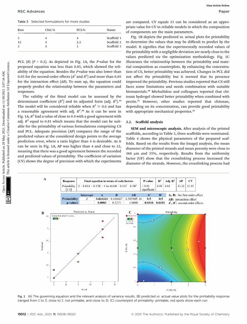
Table 3 Selected formulations for more studies
Run Chit.% PCL% Name
5 4 4 Scaffold 112 4 2.5 Scaffold 23 4 1 Scaffold 3
RSC Advances Paper
Ope
n A
cces
s A
rtic
le. P
ublis
hed
on 2
8 M
ay 2
021.
Dow
nloa
ded
on 1
1/30
/202
1 3:
07:3
4 A
M.
Thi
s ar
ticle
is li
cens
ed u
nder
a C
reat
ive
Com
mon
s A
ttrib
utio
n 3.
0 U
npor
ted
Lic
ence
.View Article Online
PCL (B) (P > 0.2). As depicted in Fig. 1A, the P-value for theproposed equation was less than 0.05, which showed the reli-ability of the equation. Besides the P-value was also lower than0.05 for the second-order effects (A2 and B2) and more than 0.05for the interaction effect (AB). To sum up, the equation couldproperly predict the relationship between the parameters andresponses.
The validity of the tted model can be assessed by thedeterminant coefficient (R2) and its adjusted form (adj. R2).19
The model will be considered reliable when R2 $ 0.6 and hasa reasonable agreement with adj. R2.20 As it can be seen inFig. 1A, R2 had a value of close to 0.9 with a good agreement withadj. R2 equal to 0.81 which means that the model can be suit-able for the printability of various formulations comprising CSand PCL. Adequate precision (AP) compares the range of thepredicted values at the considered design points to the averageprediction error, where a ratio higher than 4 is desirable. As itcan be seen in Fig. 1A, AP was higher than 4 and close to 12,meaning that there was a good agreement between the recordedand predicted values of printability. The coefficient of variation(CV) shows the degree of precision with which the experiments
Fig. 1 (A) The governing equation and the relevant analysis of variance(ranged from 1 to 3; close to 1: not printable, and close to 3), (C) counte
19512 | RSC Adv., 2021, 11, 19508–19520
are compared. CV equals 15 can be considered as an appro-priate value for CV in reliable models in which the compositionof components are the main parameters.
Fig. 1B depicts the predicted vs. actual plots for printabilityto determine the values that may be difficult to predict by themodel. It signies that the experimentally recorded values ofthe printability with a negligible deviation are nearly close to thevalues predicted via the optimization methodology. Fig. 1Cillustrates the relationship between the printability and mate-rial composition as counterplots. By enhancing the concentra-tion of CS, better printability was achieved. Changes in PCL didnot affect the printability but it seemed that its presenceimproved the printability. Previous studies reported that CS stillfaces some limitations and needs combination with suitablebiomaterials.10 Michailidou and colleagues reported that chi-tosan hydrogel showed better printability when combined withpectin.21 However, other studies reported that chitosan,depending on its concentration, can provide good printabilitywith appropriate mechanical properties.22
3.2. Scaffold analysis
SEM and microscopic analysis. Aer analysis of the printedscaffolds, according to Table 3, three scaffolds were nominated.Table 4 shows the physical parameters of the prepared scaf-folds. Based on the results from the ImageJ analysis, the meandiameter of the printed strands andmean porosity were close to360 mm and 55%, respectively. Results from the uniformityfactor (UF) show that the crosslinking process increased thediameter of the strands. However, the crosslinking process had
results, (B) predicted vs. actual value plots for the printability responserplot of printability: printable, red spots show each run.
© 2021 The Author(s). Published by the Royal Society of Chemistry
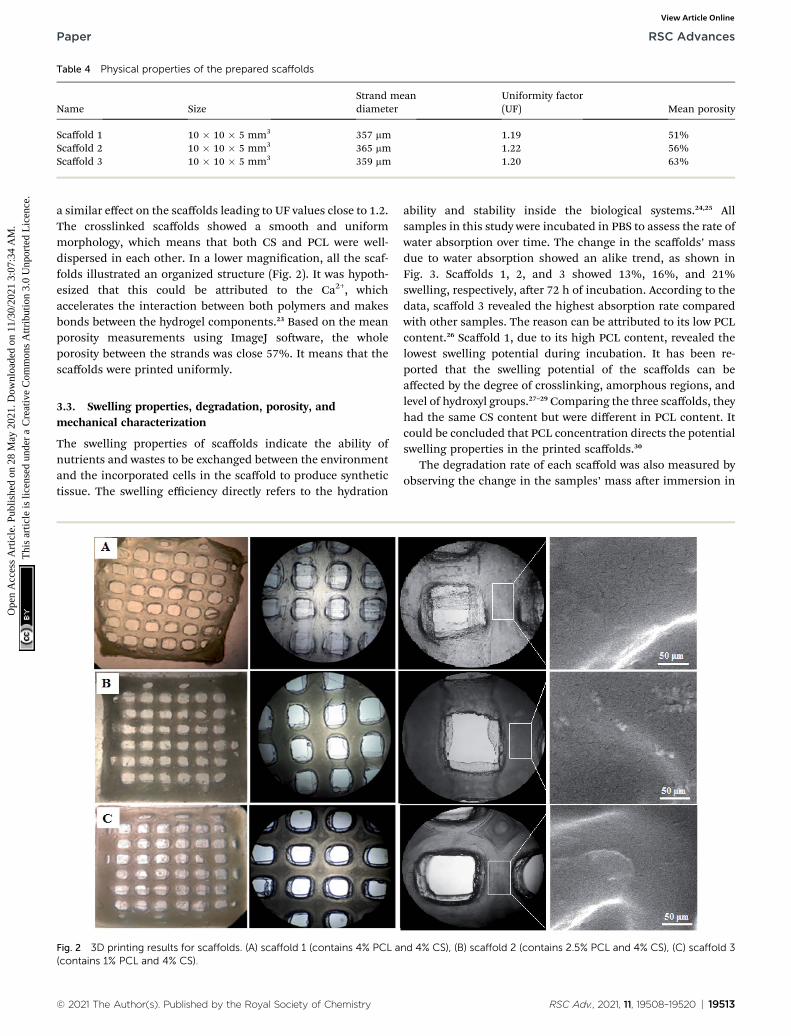
Table 4 Physical properties of the prepared scaffolds
Name SizeStrand meandiameter
Uniformity factor(UF) Mean porosity
Scaffold 1 10 � 10 � 5 mm3 357 mm 1.19 51%Scaffold 2 10 � 10 � 5 mm3 365 mm 1.22 56%Scaffold 3 10 � 10 � 5 mm3 359 mm 1.20 63%
Paper RSC Advances
Ope
n A
cces
s A
rtic
le. P
ublis
hed
on 2
8 M
ay 2
021.
Dow
nloa
ded
on 1
1/30
/202
1 3:
07:3
4 A
M.
Thi
s ar
ticle
is li
cens
ed u
nder
a C
reat
ive
Com
mon
s A
ttrib
utio
n 3.
0 U
npor
ted
Lic
ence
.View Article Online
a similar effect on the scaffolds leading to UF values close to 1.2.The crosslinked scaffolds showed a smooth and uniformmorphology, which means that both CS and PCL were well-dispersed in each other. In a lower magnication, all the scaf-folds illustrated an organized structure (Fig. 2). It was hypoth-esized that this could be attributed to the Ca2+, whichaccelerates the interaction between both polymers and makesbonds between the hydrogel components.23 Based on the meanporosity measurements using ImageJ soware, the wholeporosity between the strands was close 57%. It means that thescaffolds were printed uniformly.
3.3. Swelling properties, degradation, porosity, andmechanical characterization
The swelling properties of scaffolds indicate the ability ofnutrients and wastes to be exchanged between the environmentand the incorporated cells in the scaffold to produce synthetictissue. The swelling efficiency directly refers to the hydration
Fig. 2 3D printing results for scaffolds. (A) scaffold 1 (contains 4% PCL a(contains 1% PCL and 4% CS).
© 2021 The Author(s). Published by the Royal Society of Chemistry
ability and stability inside the biological systems.24,25 Allsamples in this study were incubated in PBS to assess the rate ofwater absorption over time. The change in the scaffolds’ massdue to water absorption showed an alike trend, as shown inFig. 3. Scaffolds 1, 2, and 3 showed 13%, 16%, and 21%swelling, respectively, aer 72 h of incubation. According to thedata, scaffold 3 revealed the highest absorption rate comparedwith other samples. The reason can be attributed to its low PCLcontent.26 Scaffold 1, due to its high PCL content, revealed thelowest swelling potential during incubation. It has been re-ported that the swelling potential of the scaffolds can beaffected by the degree of crosslinking, amorphous regions, andlevel of hydroxyl groups.27–29 Comparing the three scaffolds, theyhad the same CS content but were different in PCL content. Itcould be concluded that PCL concentration directs the potentialswelling properties in the printed scaffolds.30
The degradation rate of each scaffold was also measured byobserving the change in the samples’ mass aer immersion in
nd 4% CS), (B) scaffold 2 (contains 2.5% PCL and 4% CS), (C) scaffold 3
RSC Adv., 2021, 11, 19508–19520 | 19513
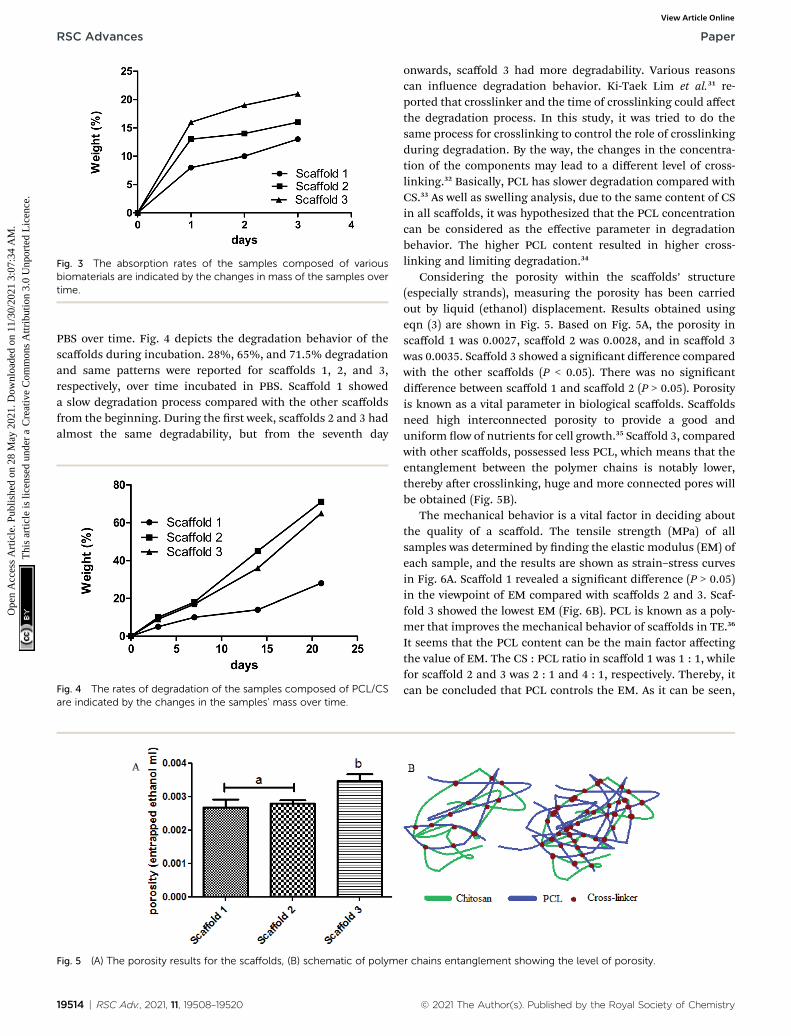
Fig. 3 The absorption rates of the samples composed of variousbiomaterials are indicated by the changes in mass of the samples overtime.
RSC Advances Paper
Ope
n A
cces
s A
rtic
le. P
ublis
hed
on 2
8 M
ay 2
021.
Dow
nloa
ded
on 1
1/30
/202
1 3:
07:3
4 A
M.
Thi
s ar
ticle
is li
cens
ed u
nder
a C
reat
ive
Com
mon
s A
ttrib
utio
n 3.
0 U
npor
ted
Lic
ence
.View Article Online
PBS over time. Fig. 4 depicts the degradation behavior of thescaffolds during incubation. 28%, 65%, and 71.5% degradationand same patterns were reported for scaffolds 1, 2, and 3,respectively, over time incubated in PBS. Scaffold 1 showeda slow degradation process compared with the other scaffoldsfrom the beginning. During the rst week, scaffolds 2 and 3 hadalmost the same degradability, but from the seventh day
Fig. 4 The rates of degradation of the samples composed of PCL/CSare indicated by the changes in the samples’ mass over time.
Fig. 5 (A) The porosity results for the scaffolds, (B) schematic of polyme
19514 | RSC Adv., 2021, 11, 19508–19520
onwards, scaffold 3 had more degradability. Various reasonscan inuence degradation behavior. Ki-Taek Lim et al.31 re-ported that crosslinker and the time of crosslinking could affectthe degradation process. In this study, it was tried to do thesame process for crosslinking to control the role of crosslinkingduring degradation. By the way, the changes in the concentra-tion of the components may lead to a different level of cross-linking.32 Basically, PCL has slower degradation compared withCS.33 As well as swelling analysis, due to the same content of CSin all scaffolds, it was hypothesized that the PCL concentrationcan be considered as the effective parameter in degradationbehavior. The higher PCL content resulted in higher cross-linking and limiting degradation.34
Considering the porosity within the scaffolds’ structure(especially strands), measuring the porosity has been carriedout by liquid (ethanol) displacement. Results obtained usingeqn (3) are shown in Fig. 5. Based on Fig. 5A, the porosity inscaffold 1 was 0.0027, scaffold 2 was 0.0028, and in scaffold 3was 0.0035. Scaffold 3 showed a signicant difference comparedwith the other scaffolds (P < 0.05). There was no signicantdifference between scaffold 1 and scaffold 2 (P > 0.05). Porosityis known as a vital parameter in biological scaffolds. Scaffoldsneed high interconnected porosity to provide a good anduniform ow of nutrients for cell growth.35 Scaffold 3, comparedwith other scaffolds, possessed less PCL, which means that theentanglement between the polymer chains is notably lower,thereby aer crosslinking, huge and more connected pores willbe obtained (Fig. 5B).
The mechanical behavior is a vital factor in deciding aboutthe quality of a scaffold. The tensile strength (MPa) of allsamples was determined by nding the elastic modulus (EM) ofeach sample, and the results are shown as strain–stress curvesin Fig. 6A. Scaffold 1 revealed a signicant difference (P > 0.05)in the viewpoint of EM compared with scaffolds 2 and 3. Scaf-fold 3 showed the lowest EM (Fig. 6B). PCL is known as a poly-mer that improves the mechanical behavior of scaffolds in TE.36
It seems that the PCL content can be the main factor affectingthe value of EM. The CS : PCL ratio in scaffold 1 was 1 : 1, whilefor scaffold 2 and 3 was 2 : 1 and 4 : 1, respectively. Thereby, itcan be concluded that PCL controls the EM. As it can be seen,
r chains entanglement showing the level of porosity.
© 2021 The Author(s). Published by the Royal Society of Chemistry
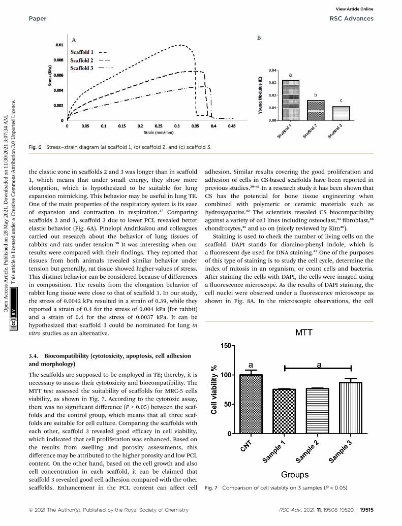
Fig. 6 Stress–strain diagram (a) scaffold 1, (b) scaffold 2, and (c) scaffold 3.
Paper RSC Advances
Ope
n A
cces
s A
rtic
le. P
ublis
hed
on 2
8 M
ay 2
021.
Dow
nloa
ded
on 1
1/30
/202
1 3:
07:3
4 A
M.
Thi
s ar
ticle
is li
cens
ed u
nder
a C
reat
ive
Com
mon
s A
ttrib
utio
n 3.
0 U
npor
ted
Lic
ence
.View Article Online
the elastic zone in scaffolds 2 and 3 was longer than in scaffold1, which means that under small energy, they show moreelongation, which is hypothesized to be suitable for lungexpansion mimicking. This behavior may be useful in lung TE.One of the main properties of the respiratory system is its easeof expansion and contraction in respiration.37 Comparingscaffolds 2 and 3, scaffold 3 due to lower PCL revealed betterelastic behavior (Fig. 6A). Pinelopi Andrikakou and colleaguescarried out research about the behavior of lung tissues ofrabbits and rats under tension.38 It was interesting when ourresults were compared with their ndings. They reported thattissues from both animals revealed similar behavior undertension but generally, rat tissue showed higher values of stress.This distinct behavior can be considered because of differencesin composition. The results from the elongation behavior ofrabbit lung tissue were close to that of scaffold 3. In our study,the stress of 0.0042 kPa resulted in a strain of 0.39, while theyreported a strain of 0.4 for the stress of 0.004 kPa (for rabbit)and a strain of 0.4 for the stress of 0.0037 kPa. It can behypothesized that scaffold 3 could be nominated for lung invitro studies as an alternative.
Fig. 7 Comparison of cell viability on 3 samples (P < 0.05).
3.4. Biocompatibility (cytotoxicity, apoptosis, cell adhesionand morphology)
The scaffolds are supposed to be employed in TE; thereby, it isnecessary to assess their cytotoxicity and biocompatibility. TheMTT test assessed the suitability of scaffolds for MRC-5 cellsviability, as shown in Fig. 7. According to the cytotoxic assay,there was no signicant difference (P > 0.05) between the scaf-folds and the control group, which means that all three scaf-folds are suitable for cell culture. Comparing the scaffolds witheach other, scaffold 3 revealed good efficacy in cell viability,which indicated that cell proliferation was enhanced. Based onthe results from swelling and porosity assessments, thisdifference may be attributed to the higher porosity and low PCLcontent. On the other hand, based on the cell growth and alsocell concentration in each scaffold, it can be claimed thatscaffold 3 revealed good cell adhesion compared with the otherscaffolds. Enhancement in the PCL content can affect cell
© 2021 The Author(s). Published by the Royal Society of Chemistry
adhesion. Similar results covering the good proliferation andadhesion of cells in CS-based scaffolds have been reported inprevious studies.39–41 In a research study it has been shown thatCS has the potential for bone tissue engineering whencombined with polymeric or ceramic materials such ashydroxyapatite.42 The scientists revealed CS biocompatibilityagainst a variety of cell lines including osteoclast,43 broblast,44
chondrocytes,45 and so on (nicely reviewed by Kim46).Staining is used to check the number of living cells on the
scaffold. DAPI stands for diamino-phenyl indole, which isa uorescent dye used for DNA staining.47 One of the purposesof this type of staining is to study the cell cycle, determine theindex of mitosis in an organism, or count cells and bacteria.Aer staining the cells with DAPI, the cells were imaged usinga uorescence microscope. As the results of DAPI staining, thecell nuclei were observed under a uorescence microscope asshown in Fig. 8A. In the microscopic observations, the cell
RSC Adv., 2021, 11, 19508–19520 | 19515
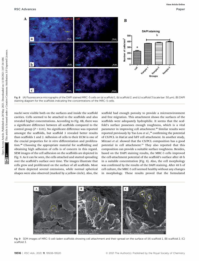
Fig. 8 (A) Fluorescencemicrographs of the DAPI stainedMRC-5 cells on (a) scaffold 1, (b) scaffold 2, and (c) scaffold 3 (scale bar: 50 mm), (B) DAPIstaining diagram for the scaffolds indicating the concentrations of the MRC-5 cells.
RSC Advances Paper
Ope
n A
cces
s A
rtic
le. P
ublis
hed
on 2
8 M
ay 2
021.
Dow
nloa
ded
on 1
1/30
/202
1 3:
07:3
4 A
M.
Thi
s ar
ticle
is li
cens
ed u
nder
a C
reat
ive
Com
mon
s A
ttrib
utio
n 3.
0 U
npor
ted
Lic
ence
.View Article Online
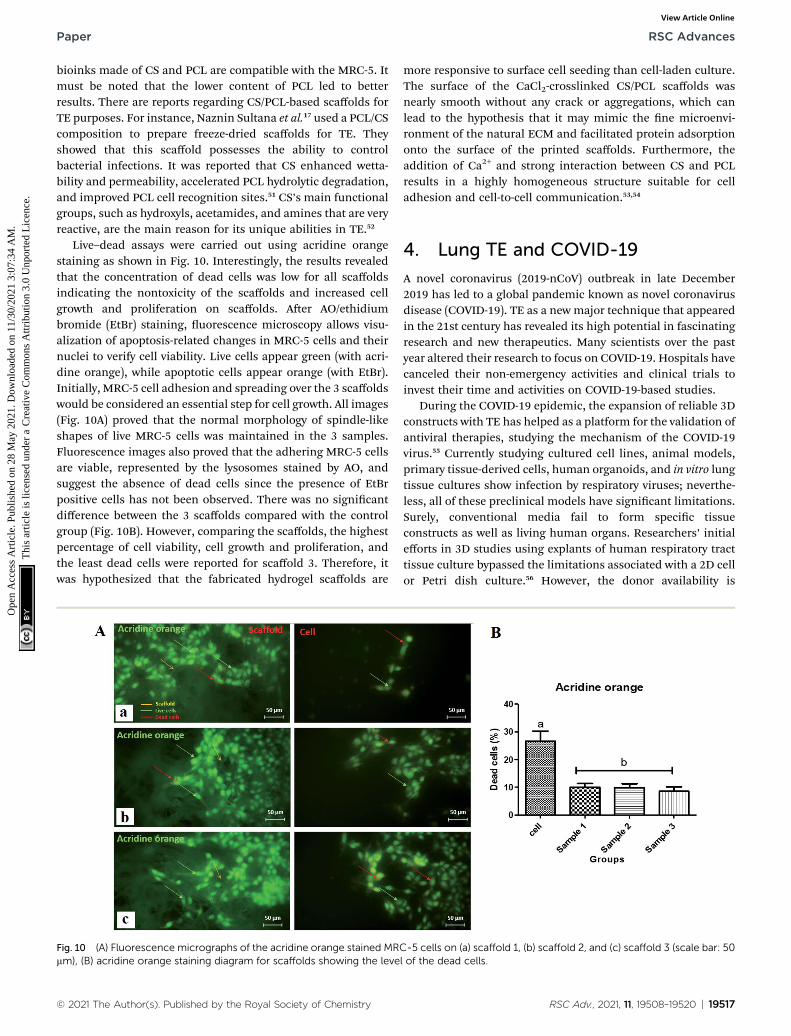
nuclei were visible both on the surfaces and inside the scaffoldcavities. Cells seemed to be attached to the scaffolds and alsorevealed higher concentrations. According to Fig. 8B, there wasa signicant difference between all scaffolds compared to thecontrol group (P < 0.01). No signicant difference was reportedamongst the scaffolds, but scaffold 3 revealed better resultsthan scaffolds 1 and 2. Adhesion of cells to their ECM is one ofthe crucial properties for in vitro differentiation and prolifera-tion.48 Choosing the appropriate material for scaffolding andobtaining high adhesion of cells is of concern in this regard.SEM images of the cell adhesion on the scaffolds are depicted inFig. 9. As it can be seen, the cells attached and started spreadingover the scaffold’s surface over time. The images illustrate thatcells grew and proliferated on the surface of all scaffolds. Mostof them depicted several extensions, while normal sphericalshapes were also observed (marked by a yellow circle). Also, the
Fig. 9 SEM images of MRC-5 cell-laden scaffolds showing cell attachmscaffold 3.
19516 | RSC Adv., 2021, 11, 19508–19520
scaffold had enough porosity to provide a microenvironmentand free migration. This attachment shows the surfaces of thescaffolds were adequately hydrophilic. It seems that the scaf-fold’s surface possesses enough roughness, which is a vitalparameter in improving cell attachment.49 Similar results werereported previously by Tao Lou et al.,50 conrming the potentialof CS/PCL in HaCat and hFF cell attachment. In another study,Mirzaei et al. showed that the CS/PCL composition has a goodpotential in cell attachment.15 They also reported that thiscomposition can provide a suitable surface roughness. Besides,based on the DAPI staining results, the MRC-5 cells improvedthe cell-attachment potential of the scaffold’s surface aer 48 hin a suitable concentration (Fig. 8). Also, the cell morphologywas conrmed by the results of the DAPI staining. Aer 48 h ofcell culture, theMRC-5 cell seemed healthy without any changesin morphology. These results proved that the formulated
ent and their spread on the surface of (A) scaffold 1, (B) scaffold 2, (C)
© 2021 The Author(s). Published by the Royal Society of Chemistry
Paper RSC Advances
Ope
n A
cces
s A
rtic
le. P
ublis
hed
on 2
8 M
ay 2
021.
Dow
nloa
ded
on 1
1/30
/202
1 3:
07:3
4 A
M.
Thi
s ar
ticle
is li
cens
ed u
nder
a C
reat
ive
Com
mon
s A
ttrib
utio
n 3.
0 U
npor
ted
Lic
ence
.View Article Online
bioinks made of CS and PCL are compatible with the MRC-5. Itmust be noted that the lower content of PCL led to betterresults. There are reports regarding CS/PCL-based scaffolds forTE purposes. For instance, Naznin Sultana et al.17 used a PCL/CScomposition to prepare freeze-dried scaffolds for TE. Theyshowed that this scaffold possesses the ability to controlbacterial infections. It was reported that CS enhanced wetta-bility and permeability, accelerated PCL hydrolytic degradation,and improved PCL cell recognition sites.51 CS’s main functionalgroups, such as hydroxyls, acetamides, and amines that are veryreactive, are the main reason for its unique abilities in TE.52
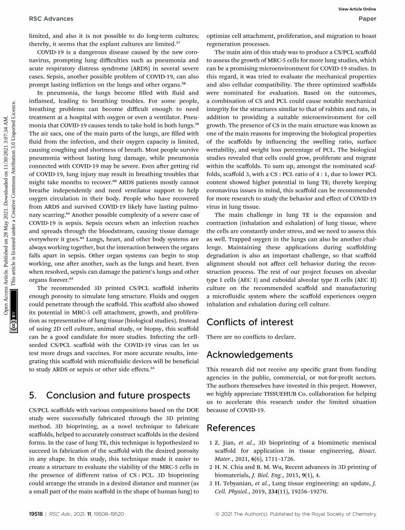
Live–dead assays were carried out using acridine orangestaining as shown in Fig. 10. Interestingly, the results revealedthat the concentration of dead cells was low for all scaffoldsindicating the nontoxicity of the scaffolds and increased cellgrowth and proliferation on scaffolds. Aer AO/ethidiumbromide (EtBr) staining, uorescence microscopy allows visu-alization of apoptosis-related changes in MRC-5 cells and theirnuclei to verify cell viability. Live cells appear green (with acri-dine orange), while apoptotic cells appear orange (with EtBr).Initially, MRC-5 cell adhesion and spreading over the 3 scaffoldswould be considered an essential step for cell growth. All images(Fig. 10A) proved that the normal morphology of spindle-likeshapes of live MRC-5 cells was maintained in the 3 samples.Fluorescence images also proved that the adhering MRC-5 cellsare viable, represented by the lysosomes stained by AO, andsuggest the absence of dead cells since the presence of EtBrpositive cells has not been observed. There was no signicantdifference between the 3 scaffolds compared with the controlgroup (Fig. 10B). However, comparing the scaffolds, the highestpercentage of cell viability, cell growth and proliferation, andthe least dead cells were reported for scaffold 3. Therefore, itwas hypothesized that the fabricated hydrogel scaffolds are
Fig. 10 (A) Fluorescence micrographs of the acridine orange stained MRmm), (B) acridine orange staining diagram for scaffolds showing the leve
© 2021 The Author(s). Published by the Royal Society of Chemistry
more responsive to surface cell seeding than cell-laden culture.The surface of the CaCl2-crosslinked CS/PCL scaffolds wasnearly smooth without any crack or aggregations, which canlead to the hypothesis that it may mimic the ne microenvi-ronment of the natural ECM and facilitated protein adsorptiononto the surface of the printed scaffolds. Furthermore, theaddition of Ca2+ and strong interaction between CS and PCLresults in a highly homogeneous structure suitable for celladhesion and cell-to-cell communication.53,54
4. Lung TE and COVID-19
A novel coronavirus (2019-nCoV) outbreak in late December2019 has led to a global pandemic known as novel coronavirusdisease (COVID-19). TE as a new major technique that appearedin the 21st century has revealed its high potential in fascinatingresearch and new therapeutics. Many scientists over the pastyear altered their research to focus on COVID-19. Hospitals havecanceled their non-emergency activities and clinical trials toinvest their time and activities on COVID-19-based studies.
During the COVID-19 epidemic, the expansion of reliable 3Dconstructs with TE has helped as a platform for the validation ofantiviral therapies, studying the mechanism of the COVID-19virus.55 Currently studying cultured cell lines, animal models,primary tissue-derived cells, human organoids, and in vitro lungtissue cultures show infection by respiratory viruses; neverthe-less, all of these preclinical models have signicant limitations.Surely, conventional media fail to form specic tissueconstructs as well as living human organs. Researchers’ initialefforts in 3D studies using explants of human respiratory tracttissue culture bypassed the limitations associated with a 2D cellor Petri dish culture.56 However, the donor availability is
C-5 cells on (a) scaffold 1, (b) scaffold 2, and (c) scaffold 3 (scale bar: 50l of the dead cells.
RSC Adv., 2021, 11, 19508–19520 | 19517
RSC Advances Paper
Ope
n A
cces
s A
rtic
le. P
ublis
hed
on 2
8 M
ay 2
021.
Dow
nloa
ded
on 1
1/30
/202
1 3:
07:3
4 A
M.
Thi
s ar
ticle
is li
cens
ed u
nder
a C
reat
ive
Com
mon
s A
ttrib
utio
n 3.
0 U
npor
ted
Lic
ence
.View Article Online
limited, and also it is not possible to do long-term cultures;thereby, it seems that the explant cultures are limited.57
COVID-19 is a dangerous disease caused by the new coro-navirus, prompting lung difficulties such as pneumonia andacute respiratory distress syndrome (ARDS) in several severecases. Sepsis, another possible problem of COVID-19, can alsoprompt lasting iniction on the lungs and other organs.58
In pneumonia, the lungs become lled with uid andinamed, leading to breathing troubles. For some people,breathing problems can become difficult enough to needtreatment at a hospital with oxygen or even a ventilator. Pneu-monia that COVID-19 causes tends to take hold in both lungs.59
The air sacs, one of the main parts of the lungs, are lled withuid from the infection, and their oxygen capacity is limited,causing coughing and shortness of breath. Most people survivepneumonia without lasting lung damage, while pneumoniaconnected with COVID-19 may be severe. Even aer getting ridof COVID-19, lung injury may result in breathing troubles thatmight take months to recover.60 ARDS patients mostly cannotbreathe independently and need ventilator support to helpoxygen circulation in their body. People who have recoveredfrom ARDS and survived COVID-19 likely have lasting pulmo-nary scarring.61 Another possible complexity of a severe case ofCOVID-19 is sepsis. Sepsis occurs when an infection reachesand spreads through the bloodstream, causing tissue damageeverywhere it goes.62 Lungs, heart, and other body systems arealways working together, but the interaction between the organsfalls apart in sepsis. Other organ systems can begin to stopworking, one aer another, such as the lungs and heart. Evenwhen resolved, sepsis can damage the patient’s lungs and otherorgans forever.63
The recommended 3D printed CS/PCL scaffold inheritsenough porosity to simulate lung structure. Fluids and oxygencould penetrate through the scaffold. This scaffold also showedits potential in MRC-5 cell attachment, growth, and prolifera-tion as representative of lung tissue (biological studies). Insteadof using 2D cell culture, animal study, or biopsy, this scaffoldcan be a good candidate for more studies. Infecting the cell-seeded CS/PCL scaffold with the COVID-19 virus can let ustest more drugs and vaccines. For more accurate results, inte-grating this scaffold with microuidic devices will be benecialto study ARDS or sepsis or other side effects.55
5. Conclusion and future prospects
CS/PCL scaffolds with various compositions based on the DOEstudy were successfully fabricated through the 3D printingmethod. 3D bioprinting, as a novel technique to fabricatescaffolds, helped to accurately construct scaffolds in the desiredforms. In the case of lung TE, this technique is hypothesized tosucceed in fabrication of the scaffold with the desired porosityin any shape. In this study, this technique made it easier tocreate a structure to evaluate the viability of the MRC-5 cells inthe presence of different ratios of CS : PCL. 3D bioprintingcould arrange the strands in a desired distance and manner (asa small part of the main scaffold in the shape of human lung) to
19518 | RSC Adv., 2021, 11, 19508–19520
optimize cell attachment, proliferation, and migration to boastregeneration processes.
The main aim of this study was to produce a CS/PCL scaffoldto assess the growth of MRC-5 cells for more lung studies, whichcan be a promising microenvironment for COVID-19 studies. Inthis regard, it was tried to evaluate the mechanical propertiesand also cellular compatibility. The three optimized scaffoldswere nominated for evaluation. Based on the outcomes,a combination of CS and PCL could cause notable mechanicalintegrity for the structures similar to that of rabbits and rats, inaddition to providing a suitable microenvironment for cellgrowth. The presence of CS in the main structure was known asone of the main reasons for improving the biological propertiesof the scaffolds by inuencing the swelling ratio, surfacewettability, and weight loss percentage of PCL. The biologicalstudies revealed that cells could grow, proliferate and migratewithin the scaffolds. To sum up, amongst the nominated scaf-folds, scaffold 3, with a CS : PCL ratio of 4 : 1, due to lower PCLcontent showed higher potential in lung TE; thereby keepingcoronavirus issues in mind, this scaffold can be recommendedfor more research to study the behavior and effect of COVID-19virus in lung tissue.
The main challenge in lung TE is the expansion andcontraction (inhalation and exhalation) of lung tissue, wherethe cells are constantly under stress, and we need to assess thisas well. Trapped oxygen in the lungs can also be another chal-lenge. Maintaining these applications during scaffoldingdegradation is also an important challenge, so that scaffoldalignment should not affect cell behavior during the recon-struction process. The rest of our project focuses on alveolartype I cells (AEC I) and cuboidal alveolar type II cells (AEC II)culture on the recommended scaffold and manufacturinga microuidic system where the scaffold experiences oxygeninhalation and exhalation during cell culture.
Conflicts of interest
There are no conicts to declare.
Acknowledgements
This research did not receive any specic grant from fundingagencies in the public, commercial, or not-for-prot sectors.The authors themselves have invested in this project. However,we highly appreciate TISSUEHUB Co. collaboration for helpingus to accelerate this research under the limited situationbecause of COVID-19.
References
1 Z. Jian, et al., 3D bioprinting of a biomimetic meniscalscaffold for application in tissue engineering, Bioact.Mater., 2021, 6(6), 1711–1726.
2 H. N. Chia and B. M. Wu, Recent advances in 3D printing ofbiomaterials, J. Biol. Eng., 2015, 9(1), 4.
3 H. Tebyanian, et al., Lung tissue engineering: an update, J.Cell. Physiol., 2019, 234(11), 19256–19270.
© 2021 The Author(s). Published by the Royal Society of Chemistry
Paper RSC Advances
Ope
n A
cces
s A
rtic
le. P
ublis
hed
on 2
8 M
ay 2
021.
Dow
nloa
ded
on 1
1/30
/202
1 3:
07:3
4 A
M.
Thi
s ar
ticle
is li
cens
ed u
nder
a C
reat
ive
Com
mon
s A
ttrib
utio
n 3.
0 U
npor
ted
Lic
ence
.View Article Online
4 F. Akter, L. Berhan-Tewolde and A. De Mel, Lung TissueEngineering, in Tissue Engineering Made Easy, ed. F. Akter,Academic Press, 2016, ch. 7, pp. 67–75.
5 S. Ullah and X. Chen, Fabrication, applications andchallenges of natural biomaterials in tissue engineering,Appl. Mater. Today, 2020, 20, 100656.
6 M. M. Islam, et al., Chitosan based bioactive materials intissue engineering applications-a review, Bioact. Mater.,2020, 5(1), 164–183.
7 D. Semnani, et al., Evaluation of PCL/chitosan electrospunnanobers for liver tissue engineering, Int. J. Polym. Mater.Polym. Biomater., 2017, 66(3), 149–157.
8 C. P. Jimenez-Gomez and J. A. Cecilia, Chitosan: A NaturalBiopolymer with a Wide and Varied Range of Applications,Molecules, 2020, 25(17), 3981.
9 A. P. Price, et al., Automated decellularization of intact,human-sized lungs for tissue engineering, Tissue Eng., PartC, 2015, 21(1), 94–103.
10 M. Sahranavard, et al., A Critical Review on ThreeDimensional-Printed Chitosan Hydrogels for Developmentof Tissue Engineering, Bioprinting, 2019, 17, e00063.
11 M. C. Nerantzaki, et al., New N-(2-carboxybenzyl)chitosancomposite scaffolds containing nanoTiO2 or bioactive glasswith enhanced cell proliferation for bone-tissueengineering applications, Int. J. Polym. Mater. Polym.Biomater., 2017, 66(2), 71–81.
12 B. Sun, et al., The osteogenic differentiation of dog bonemarrow mesenchymal stem cells in a thermo-sensitiveinjectable chitosan/collagen/b-glycerophosphate hydrogel:in vitro and in vivo, J. Mater. Sci.: Mater. Med., 2011, 22(9),2111–2118.
13 M. Fadaie, et al., Incorporation of nanobrillated chitosaninto electrospun PCL nanobers makes scaffolds withenhanced mechanical and biological properties,Carbohydr. Polym., 2018, 199, 628–640.
14 M. Abrisham, et al., The role of polycaprolactone-triol (PCL-T) in biomedical applications: a state-of-the-art review, Eur.Polym. J., 2020, 131, 109701.
15 M. Fadaie and E. Mirzaei, Nanobrillated chitosan/polycaprolactone bionanocomposite scaffold withimproved tensile strength and cellular behavior, Nanomed.J., 2018, 5(2), 77–89.
16 A. Sarasam and S. V. Madihally, Characterization ofchitosan-polycaprolactone blends for tissue engineeringapplications, Biomaterials, 2005, 26(27), 5500–5508.
17 R. Mad Jin, et al., Porous PCL/Chitosan and nHA/PCL/Chitosan Scaffolds for Tissue Engineering Applications:Fabrication and Evaluation, J. Nanomater., 2015, 2015,357372.
18 J. Babilotte, et al., Development and characterization ofa PLGA-HA composite material to fabricate 3D-printedscaffolds for bone tissue engineering, Mater. Sci. Eng., C,2021, 118, 111334.
19 O. Harel, The estimation of R2 and adjusted R2 inincomplete data sets using multiple imputation, J. Appl.Stat., 2009, 36, 1109–1118.
© 2021 The Author(s). Published by the Royal Society of Chemistry
20 L. Sasikala, R. Rathinamoorthy and B. Dhurai, Optimizationof process conditions for chitosan-manuka honey lm aswound contact layer for wound dressings, Wound Med.,2018, 23, 11–21.
21 G. Michailidou, et al., Preliminary Evaluation of 3D PrintedChitosan/Pectin Constructs for Biomedical Applications,Mar. Drugs, 2021, 19(1), 36.
22 Q. Wu, T. Daniel and M.-C. Heuzey, Processing andProperties of Chitosan Inks for 3D Printing of HydrogelMicrostructures, ACS Biomater. Sci. Eng., 2018, 4, 2643–2652.
23 S. D. Dutta, et al., 3D-printed bioactive and biodegradablehydrogel scaffolds of alginate/gelatin/cellulose nanocrystalsfor tissue engineering, Int. J. Biol. Macromol., 2021, 167,644–658.
24 D. Chawla, et al., 3D bioprinted alginate-gelatin basedscaffolds for so tissue engineering, Int. J. Biol. Macromol.,2020, 144, 560–567.
25 W. Xu, et al., On Low-Concentration Inks Formulated byNanocellulose Assisted with Gelatin Methacrylate (GelMA)for 3D Printing toward Wound Healing Application, ACSAppl. Mater. Interfaces, 2019, 11(9), 8838–8848.
26 R. Mad Jin, et al., Porous PCL/chitosan and nHA/PCL/chitosan scaffolds for tissue engineering applications:fabrication and evaluation, J. Nanomater., 2015, 2015, DOI:10.1155/2015/357372.
27 H. S. Mansur, et al., FTIR spectroscopy characterization ofpoly(vinyl alcohol) hydrogel with different hydrolysisdegree and chemically crosslinked with glutaraldehyde,Mater. Sci. Eng., C, 2008, 28(4), 539–548.
28 J. Zhu and R. E. Marchant, Design properties of hydrogeltissue-engineering scaffolds, Expert Rev. Med. Devices, 2011,8(5), 607–626.
29 R. M. Felfel, et al., Structural, mechanical and swellingcharacteristics of 3D scaffolds from chitosan-agaroseblends, Carbohydr. Polym., 2019, 204, 59–67.
30 R. Soni, et al., Synthesis and optimization of PCL-bioactiveglass composite scaffold for bone tissue engineering,Mater. Today: Proc., 2019, 15, 294–299.
31 S. D. Dutta, et al., 3D-printed bioactive and biodegradablehydrogel scaffolds of alginate/gelatin/cellulose nanocrystalsfor tissue engineering, Int. J. Biol. Macromol., 2020, 644–658.
32 N. Hiraishi, et al., Susceptibility of a polycaprolactone-basedroot canal-lling material to degradation. III. Turbidimetricevaluation of enzymatic hydrolysis, J. Endod., 2007, 33(8),952–956.
33 A. R. Sarasam, R. K. Krishnaswamy and S. V. Madihally,Blending chitosan with polycaprolactone: effects onphysicochemical and antibacterial properties,Biomacromolecules, 2006, 7(4), 1131–1138.
34 T. Fukunishi, et al., Tissue-engineered small diameterarterial vascular gras from cell-free nanober PCL/chitosan scaffolds in a sheep model, PLoS One, 2016, 11(7),e0158555.
35 V. Karageorgiou and D. Kaplan, Porosity of 3D biomaterialscaffolds and osteogenesis, Biomaterials, 2005, 26(27),5474–5491.
RSC Adv., 2021, 11, 19508–19520 | 19519
RSC Advances Paper
Ope
n A
cces
s A
rtic
le. P
ublis
hed
on 2
8 M
ay 2
021.
Dow
nloa
ded
on 1
1/30
/202
1 3:
07:3
4 A
M.
Thi
s ar
ticle
is li
cens
ed u
nder
a C
reat
ive
Com
mon
s A
ttrib
utio
n 3.
0 U
npor
ted
Lic
ence
.View Article Online
36 L. Leung, A. DiRosa and H. Naguib, Physical and MechanicalProperties of Poly(E-Caprolactone)–Hydroxyapatite Compositesfor Bone Tissue Engineering Applications, 2009, vol. 2, DOI:10.1115/IMECE2009-11273.
37 E. De Robertis, et al., Elastic properties of the lung and thechest wall in young and adult healthy pigs, Eur. Respir. J.,2001, 17(4), 703–711.
38 P. Andrikakou, K. Vickraman andH. Arora, On the behaviourof lung tissue under tension and compression, Sci. Rep.,2016, 6, 36642.
39 S. Luna, et al., Cell Adhesion and Proliferation ontoChitosan-based Membranes Treated by Plasma SurfaceModication, J. Biomater. Appl., 2011, 26, 101–116.
40 J. Jagur-Grodzinski, Biomedical applications of polymers2001-2002, e-Polym., 2003, 3(1), DOI: 10.1515/epoly.2003.3.1.141.
41 A. Madni, et al., Recent Advancements in Applications ofChitosan-based Biomaterials for Skin Tissue Engineering,J. Bioresour. Bioprod., 2021, 11–25.
42 S. K. L. Levengood and M. Zhang, Chitosan-based scaffoldsfor bone tissue engineering, J. Mater. Chem. B, 2014, 2(21),3161–3184.
43 J. Venkatesan and S.-K. Kim, Chitosan composites for bonetissue engineering—an overview, Mar. Drugs, 2010, 8(8),2252–2266.
44 L. Ma, et al., Collagen/chitosan porous scaffolds withimproved biostability for skin tissue engineering,Biomaterials, 2003, 24(26), 4833–4841.
45 J. K. Francis Suh and H. W. T. Matthew, Application ofchitosan-based polysaccharide biomaterials in cartilagetissue engineering: a review, Biomaterials, 2000, 21(24),2589–2598.
46 I.-Y. Kim, et al., Chitosan and its derivatives for tissueengineering applications, Biotechnol. Adv., 2008, 26(1), 1–21.
47 B. I. Tarnowski, F. G. Spinale and J. H. Nicholson, DAPI asa useful stain for nuclear quantitation, Biotech. Histochem.,1991, 66(6), 296–302.
48 S. C. Taylor, et al., The Role of Synaptic Cell AdhesionMolecules and Associated Scaffolding Proteins in SocialAffiliative Behaviors, Biol. Psychiatry, 2020, 442–451.
49 T.-W. Chung, et al., Enhancement of the growth of humanendothelial cells by surface roughness at nanometer scale,Biomaterials, 2003, 24(25), 4655–4661.
50 T. Lou, et al., Bi-layer scaffold of chitosan/PCL-nanobrousmat and PLLA-microporous disc for skin tissueengineering, J. Biomed. Nanotechnol., 2014, 10(6), 1105–1113.
19520 | RSC Adv., 2021, 11, 19508–19520
51 S. C. Neves, et al., Chitosan/poly(3-caprolactone) blendscaffolds for cartilage repair, Biomaterials, 2011, 32(4),1068–1079.
52 V. Mourya and N. N. Inamdar, Chitosan-modications andapplications: opportunities galore, React. Funct. Polym.,2008, 68(6), 1013–1051.
53 S. D. Dutta, D. K. Patel and K.-T. Lim, Functional cellulose-based hydrogels as extracellular matrices for tissueengineering, J. Biol. Eng., 2019, 13(1), 55.
54 D. K. Patel, et al., Bioactive electrospun nanocompositescaffolds of poly (lactic acid)/cellulose nanocrystals forbone tissue engineering, Int. J. Biol. Macromol., 2020, 162,1429–1441.
55 L. Si, et al., Human organs-on-chips as tools for repurposingapproved drugs as potential inuenza and COVID-19therapeutics in viral pandemics, bioRxiv, 2020, DOI:10.1101/2020.04.13.039917.
56 W. Liu, et al., Learning from the past: possible urgentprevention and treatment options for severe acuterespiratory infections caused by 2019-nCoV, Chembiochem,2020, 730–738.
57 J.-C. Grivel and L. Margolis, Use of human tissue explants tostudy human infectious agents, Nat. Protoc., 2009, 4(2), 256.
58 M. A. Khan, et al., Prediction of COVID-19 - Pneumoniabased on Selected Deep Features and One Class KernelExtreme Learning Machine, Comput. Electr. Eng., 2021, 90,106960.
59 M. N. Aydemir, et al., Computationally predicted SARS-COV-2 encoded microRNAs target NFKB, JAK/STAT and TGFBsignaling pathways, Gene Rep., 2021, 22, 101012.
60 M. Canayaz, MH-COVIDNet: Diagnosis of COVID-19 usingdeep neural networks and meta-heuristic-based featureselection on X-ray images, Biomed. Signal Process. Control,2021, 64, 102257.
61 R. Boostani, et al., COVID-19 associated with sensorimotorpolyradiculoneuropathy and skin lesions: a case report, J.Neuroimmunol., 2021, 350, DOI: 10.1016/j.jneuroim.2020.577434.
62 C. Lee and W. J. Choi, Overview of COVID-19 inammatorypathogenesis from the therapeutic perspective, Arch.Pharmacal Res., 2021, 99–116.
63 N. Moian, P. Rezaei Hachesu and T. Samad-Soltani,Information Technology Efforts Against COVID-19: AReview of Open Source Projects, J. Adv. Med. Biomed. Res.,2021, 29(132), 1–13.
© 2021 The Author(s). Published by the Royal Society of Chemistry


![Development of Electrospun Chitosan-Polyethylene … · 2018. 4. 2. · wound dressing applications [14]. To improve the mechanical properties of electrospun fibrinogen scaffold,](https://static.fdocuments.in/doc/165x107/60f7fabcc849a8662229f709/development-of-electrospun-chitosan-polyethylene-2018-4-2-wound-dressing-applications.jpg)