3D Parametric Modelling of Milling Cutter Geometry...
6
International Journal of Science, Technology and Society 2016; 4(2): 35-40 http://www.sciencepublishinggroup.com/j/ijsts doi: 10.11648/j.ijsts.20160402.13 ISSN: 2330-7412 (Print); ISSN: 2330-7420 (Online) 3D Parametric Modelling of Milling Cutter Geometry from Analytical Analysis A. Nasri 1, 2, * , J. Slaimi 1, 2 , W. Bouzid Sai 2 1 Department of Mechanical Engineering, University of Tunis El Manar, National Engineering School of Tunis, Tunis, Tunisia 2 National Engineering School of Sfax, Sfax, Tunisia Email address: [email protected] (A. Nasri) * Corresponding author To cite this article: A. Nasri, J. Slaimi, W. Bouzid Sai. 3D Parametric Modelling of Milling Cutter Geometry from Analytical Analysis. International Journal of Science, Technology and Society. Vol. 4, No. 2, 2016, pp. 35-40. doi: 10.11648/j.ijsts.20160402.13 Received: October 24, 2015; Accepted: November 9, 2015; Published: April 12, 2016 Abstract: Numerical simulation of milling process needs an accurate model of cutting tool. In this paper, we describe the methodology developed to design flat and ball end mills in three-dimensional configuration. The geometry of these cutters is issued from an analytic study based on oblique cutting theory. The described model is performed by using parametric CAD software. Hence, it involves a big number of variables as the diameter, the helix, the rake and the clearance angles and the teeth number. Furthermore, the modelled cutters are compared to real scanned ones in order to validate the used methodology. The results show a good accuracy regarding the global three-dimensional shape. Keywords: Milling Cutter, CAD Modelling, Digitizing Techniques 1. Introduction As milling is one of the most frequently used machining processes, the knowledge of its optimal cutting parameters is essential. Many investigations are conducted, in this context, to model cutting forces, temperature distribution, chip morphology, machined parts quality and tool life. In their works, researchers pay more attention, commonly, to study the effect of tool geometry because of its complexity and the intermittent character of the milling process, by using analytical modelling with simplified hypothesis, numerical analysis or/and experimental approaches. Gradisek and et al. [1] presented expressions for mechanistic identification of cutting force coefficients for a general helical end mill based on a generalized mathematical model of the outer cutter, developed by Engin [2], and which is valid for a variety of end mill shapes, such as cylindrical, taper, ball nose, etc. In the same context, a predictive force model for ball-end milling based on thermomechanical modelling of oblique cutting was expressed by Fontaine [3]. The tool geometry is decomposed into a series of axial elementary cutting edges. At any active tooth element, the chip formation is obtained from an oblique cutting process characterised by local undeformed chip section and local cutting angles. Ben Said and et al. [4] proposed later an analytical model to estimate the cutting forces and the tool geometry in relation to the flank wear when milling with a ball-end mill. Moreover, in his work including instantaneous cutting forces and finished workpiece topography in ball end milling, Lazoglu [5] mentioned that the mill cutting edge geometry can be represented either by an explicit mathematical model supplied by cutter manufacturer or via polynomial fitting to CMM data set. Although the accuracy of the above mentioned ways to model the milling cutter geometry, it is believed that the use of graphical and numerical approaches is better since it offers visual information and three-dimensional representation of the cutting process. In the literature, one can mainly distinguish two methods to represent the milling cutter. In the first one, the tool is replaced by graphical entities (cylinder or/and sphere) [5-7], and thus, the milling process is materialized by only the undeformed chip and one can rule out the influence of the geometric parameters of the cutter such as the rake and flank angles. In the second method, in order to simulate the milling
Transcript of 3D Parametric Modelling of Milling Cutter Geometry...

International Journal of Science, Technology and Society 2016; 4(2): 35-40
http://www.sciencepublishinggroup.com/j/ijsts
doi: 10.11648/j.ijsts.20160402.13
ISSN: 2330-7412 (Print); ISSN: 2330-7420 (Online)
3D Parametric Modelling of Milling Cutter Geometry from Analytical Analysis
A. Nasri1, 2, *
, J. Slaimi1, 2
, W. Bouzid Sai2
1Department of Mechanical Engineering, University of Tunis El Manar, National Engineering School of Tunis, Tunis, Tunisia 2National Engineering School of Sfax, Sfax, Tunisia
Email address: [email protected] (A. Nasri) *Corresponding author
To cite this article: A. Nasri, J. Slaimi, W. Bouzid Sai. 3D Parametric Modelling of Milling Cutter Geometry from Analytical Analysis. International Journal of
Science, Technology and Society. Vol. 4, No. 2, 2016, pp. 35-40. doi: 10.11648/j.ijsts.20160402.13
Received: October 24, 2015; Accepted: November 9, 2015; Published: April 12, 2016
Abstract: Numerical simulation of milling process needs an accurate model of cutting tool. In this paper, we describe the
methodology developed to design flat and ball end mills in three-dimensional configuration. The geometry of these cutters is
issued from an analytic study based on oblique cutting theory. The described model is performed by using parametric CAD
software. Hence, it involves a big number of variables as the diameter, the helix, the rake and the clearance angles and the teeth
number. Furthermore, the modelled cutters are compared to real scanned ones in order to validate the used methodology. The
results show a good accuracy regarding the global three-dimensional shape.
Keywords: Milling Cutter, CAD Modelling, Digitizing Techniques
1. Introduction
As milling is one of the most frequently used machining
processes, the knowledge of its optimal cutting parameters is
essential. Many investigations are conducted, in this context,
to model cutting forces, temperature distribution, chip
morphology, machined parts quality and tool life. In their
works, researchers pay more attention, commonly, to study the
effect of tool geometry because of its complexity and the
intermittent character of the milling process, by using
analytical modelling with simplified hypothesis, numerical
analysis or/and experimental approaches.
Gradisek and et al. [1] presented expressions for
mechanistic identification of cutting force coefficients for a
general helical end mill based on a generalized mathematical
model of the outer cutter, developed by Engin [2], and which
is valid for a variety of end mill shapes, such as cylindrical,
taper, ball nose, etc.
In the same context, a predictive force model for ball-end
milling based on thermomechanical modelling of oblique
cutting was expressed by Fontaine [3]. The tool geometry is
decomposed into a series of axial elementary cutting edges. At
any active tooth element, the chip formation is obtained from
an oblique cutting process characterised by local undeformed
chip section and local cutting angles.
Ben Said and et al. [4] proposed later an analytical model to
estimate the cutting forces and the tool geometry in relation to
the flank wear when milling with a ball-end mill.
Moreover, in his work including instantaneous cutting
forces and finished workpiece topography in ball end milling,
Lazoglu [5] mentioned that the mill cutting edge geometry can
be represented either by an explicit mathematical model
supplied by cutter manufacturer or via polynomial fitting to
CMM data set.
Although the accuracy of the above mentioned ways to
model the milling cutter geometry, it is believed that the use of
graphical and numerical approaches is better since it offers
visual information and three-dimensional representation of the
cutting process.
In the literature, one can mainly distinguish two methods to
represent the milling cutter. In the first one, the tool is replaced
by graphical entities (cylinder or/and sphere) [5-7], and thus,
the milling process is materialized by only the undeformed
chip and one can rule out the influence of the geometric
parameters of the cutter such as the rake and flank angles.
In the second method, in order to simulate the milling
36 A. Nasri et al.: 3D Parametric Modelling of Milling Cutter Geometry from Analytical Analysis
process with numerical analysis, authors are constrained to
reproduce the 3D model of the milling cutter as an element of
the global model geometry including essentially the tool and
the workpiece.
Soo et al. [8] developed a three-dimensional finite element
model of the ball nose end milling process, using ABAQUS
Explicit to demonstrate the high-speed machining of Inconel
718 superalloy. In this work, Ball nose end mill geometry was
based on commercial tools and was created externally on a
computer aided design system (AutoCAD) and imported into
the FE domain.
Pantalé [9] presented a three-dimensional oblique model to
simulate the unsteady-state process of chip formation in a
milling application. In this model, performed with finite
elements package Abaqus, only a part of the twist milling
cutter has been modeled to reduce the number of elements.
In the work of Fontaine [10], a 3D FEM model of shoulder
milling on a 304L stainless steel has been developed with the
LS-Dyna commercial software. The used tool geometry was
obtained from a digitalized model of a real milling cutter by
using a 3D reconstruction technique.
Nasri [11] proposed a 3D steady-state FE model to
simulate the temperature distribution in ball end milling. The
geometry of the 3D model, including the chip, the workpiece,
the shear zones and the tool, is designed on CAD package
(CATIA) based on experimental and analytical modelling of
the ball end mill.
Recently, Diciuc [12] presented a review of the main
modelling types of the cutting process using ball nose end
mills, underlining the specificity, the advantages and
disadvantages for each type.
The purpose of this work is to generate 3D parametric
models of flat and ball end milling cutters by using parametric
CAD software, to be integrated in FE simulation studies of
milling process.
The paper is organized as follows: Section 2 presents a brief
review of the analytical modelling of milling cutter geometry;
in Section 3, the methodology used to design the parametric
model is developed for both flat and ball end mills. Finally,
Section 4 describes the experimental technique used to rebuild
real mills and the comparison between 3D reconstructed and
developed models.
2. Analytical Modelling of Milling Cutter
Geometry
End milling cutters are multi-point cutters with cutting
edges both on the end face and the circumferential surface of
the cutter [13]. In the following, we will focus our interest
only on the ball and flat end mills.
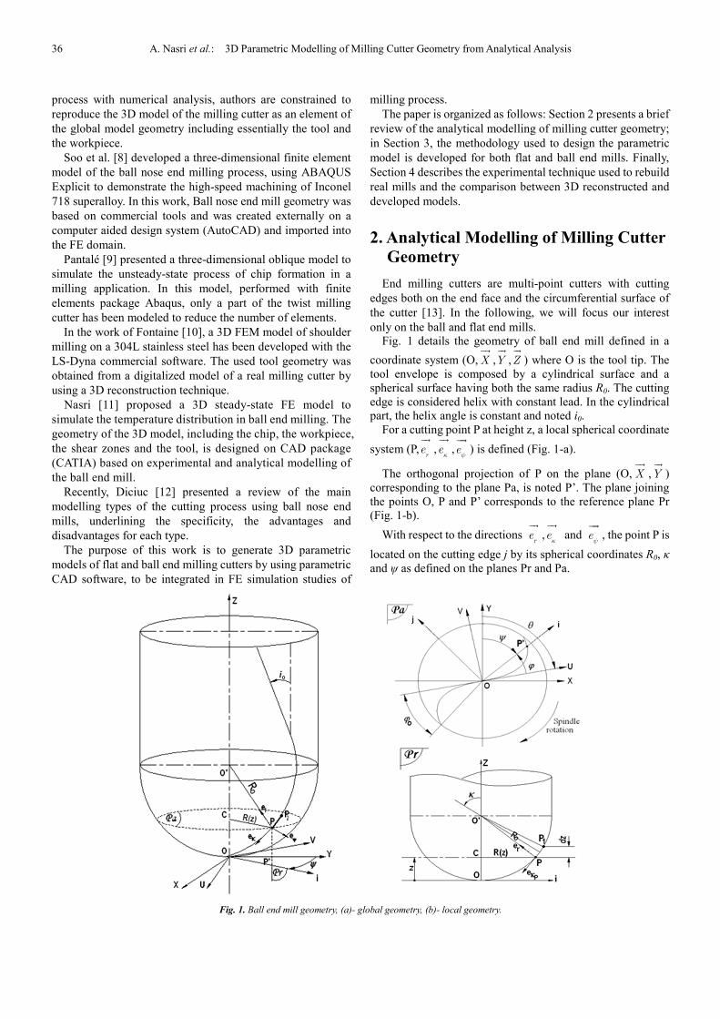
Fig. 1 details the geometry of ball end mill defined in a
coordinate system (O,��
X ,��
Y ,��
Z ) where O is the tool tip. The
tool envelope is composed by a cylindrical surface and a
spherical surface having both the same radius R0. The cutting
edge is considered helix with constant lead. In the cylindrical
part, the helix angle is constant and noted i0.
For a cutting point P at height z, a local spherical coordinate
system (P,��
re ,��
eκ
,���
eψ
) is defined (Fig. 1-a).
The orthogonal projection of P on the plane (O,��
X ,��
Y )
corresponding to the plane Pa, is noted P’. The plane joining
the points O, P and P’ corresponds to the reference plane Pr
(Fig. 1-b).
With respect to the directions ��
re ,��
eκ
and ���
eψ
, the point P is
located on the cutting edge j by its spherical coordinates R0, κ
and ψ as defined on the planes Pr and Pa.
Fig. 1. Ball end mill geometry, (a)- global geometry, (b)- local geometry.
International Journal of Science, Technology and Society 2016; 4(2): 35-40 37
These angular positions can be written as following:
( ) 0
0
cos−
=R z
zR
κ (1)
( )( )( , ) 1 2 / ( )= + − −f
z j N zψ θ θ π ϕ (2)
where θ is the rotation angle of the mill, Nf is the number of
teeth and ϕ (z) is the lag angle measured between the tool tip
and the current point P and expressed as:
( )( )( )
0
0
tantan= =
z i zz iz
R R zϕ (3)
Thus, the local helix angle i(z) can be written as:
( )( )
0
0
tan tan=R z
i z iR
(4)
R(z) is expressed as:
( )2
0
0
1 1 = − −
zR z R
R (5)
The orthogonal projection of another cutting point P2 (Fig.
1-a) on Pr corresponds to the drawn point P1 on Fig. 1-b. dz is
the incremental distance between P and P1.
The modelling of the flat end mill geometry is issued from
the study established above since we consider only the
cylindrical part of the tool. The helix angle and the cutter
radius remain both constant.
3. Model Design Methodology
For both end mill types, the technique used to design the
three-dimensional model is sweeping and rotating an initial
cross-sectional profile of the cutter along the Z direction.
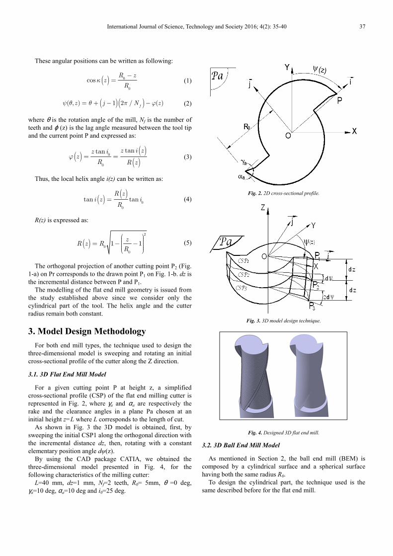
3.1. 3D Flat End Mill Model
For a given cutting point P at height z, a simplified
cross-sectional profile (CSP) of the flat end milling cutter is
represented in Fig. 2, where γa and αa are respectively the
rake and the clearance angles in a plane Pa chosen at an
initial height z=L where L corresponds to the length of cut.
As shown in Fig. 3 the 3D model is obtained, first, by
sweeping the initial CSP1 along the orthogonal direction with
the incremental distance dz, then, rotating with a constant
elementary position angle dψ(z).
By using the CAD package CATIA, we obtained the
three-dimensional model presented in Fig. 4, for the
following characteristics of the milling cutter:
L=40 mm, dz=1 mm, Nf=2 teeth, R0= 5mm, θ =0 deg,
γa=10 deg, αa=10 deg and i0=25 deg.
Fig. 2. 2D cross-sectional profile.
Fig. 3. 3D model design technique.
Fig. 4. Designed 3D flat end mill.
3.2. 3D Ball End Mill Model
As mentioned in Section 2, the ball end mill (BEM) is
composed by a cylindrical surface and a spherical surface
having both the same radius R0.
To design the cylindrical part, the technique used is the
same described before for the flat end mill.

38 A. Nasri et al.: 3D Parametric Modelling of Milling Cutter Geometry from Analytical Analysis
Fig. 5. BEM model design technique.
Fig. 6. Designed 3D ball end mill.
The spherical part results from the junction of iterative 2D
shapes obtained by sweeping and rotating an initial
cross-sectional profile (CSP) of the ball end cutter given at an
initial height z= R0 taking into account at each iteration a
CSP reduction ratio (Fig. 5).
The CSP radius at any instance z, is R(z). The ratio by
witch the CSP reduces while moving towards the tip of the
ball end cutter is R(z)/ R0.
The obtained model for: Nf=2 teeth, R0= 5mm, θ =0 deg,
γa=10 deg, αa=10 deg and i0=25 deg is presented in Fig. 6.
4. The Model Validation
To examine the validity of the above-mentioned technique,
an experimental methodology was performed. This
methodology consists on rebuilding 3D milling cutters in
order to check the real geometry and to compare it to the
developed model.
4.1. Experimental Approach
To digitize the milling cutters, a laser scanner PICZA LPX
800 was used. This set up working with spot-beam
triangulation scanning method has a resolution of 0.2 mm.
The digitizing operation is controlled from Pixform Pro II
software (Fig. 7-a).
Seen the mill revolved geometry, the rotary scanning mode
was adopted (Fig. 7-b).
A dry powder developer is applied first to the mill surface.
Then, once placed in the rotating table, a laser beam travels
vertically up the tool to generate a digital data file.
Fig. 7. (a) Experimental set up and (b) schema of scanning mode principle.
4.2. Scanning Results and Discussion
Table 1. Used tools characteristics.
Type Code Radius
R0 (mm)
Helix angle
i0 (deg)
Rake
angle γγγγa
(deg)
Length of
cut L
(mm)
Flat end C110 6 30 12 27.5
Ball end C500 8 30 12 30
4 30 12 20
Fig. 8. Scanned milling cutters (a) flat end mill, (b) ball end mills.
International Journal of Science, Technology and Society 2016; 4(2): 35-40 39
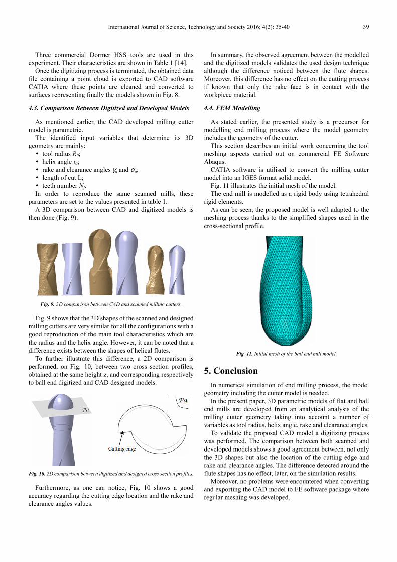
Three commercial Dormer HSS tools are used in this
experiment. Their characteristics are shown in Table 1 [14].
Once the digitizing process is terminated, the obtained data
file containing a point cloud is exported to CAD software
CATIA where these points are cleaned and converted to
surfaces representing finally the models shown in Fig. 8.
4.3. Comparison Between Digitized and Developed Models
As mentioned earlier, the CAD developed milling cutter
model is parametric.
The identified input variables that determine its 3D
geometry are mainly:
� tool radius R0;
� helix angle i0;
� rake and clearance angles γa and αa;
� length of cut L;
� teeth number Nf.
In order to reproduce the same scanned mills, these
parameters are set to the values presented in table 1.
A 3D comparison between CAD and digitized models is
then done (Fig. 9).
Fig. 9. 3D comparison between CAD and scanned milling cutters.
Fig. 9 shows that the 3D shapes of the scanned and designed
milling cutters are very similar for all the configurations with a
good reproduction of the main tool characteristics which are
the radius and the helix angle. However, it can be noted that a
difference exists between the shapes of helical flutes.
To further illustrate this difference, a 2D comparison is
performed, on Fig. 10, between two cross section profiles,
obtained at the same height z, and corresponding respectively
to ball end digitized and CAD designed models.
Fig. 10. 2D comparison between digitized and designed cross section profiles.
Furthermore, as one can notice, Fig. 10 shows a good
accuracy regarding the cutting edge location and the rake and
clearance angles values.
In summary, the observed agreement between the modelled
and the digitized models validates the used design technique
although the difference noticed between the flute shapes.
Moreover, this difference has no effect on the cutting process
if known that only the rake face is in contact with the
workpiece material.
4.4. FEM Modelling
As stated earlier, the presented study is a precursor for
modelling end milling process where the model geometry
includes the geometry of the cutter.
This section describes an initial work concerning the tool
meshing aspects carried out on commercial FE Software
Abaqus.
CATIA software is utilised to convert the milling cutter
model into an IGES format solid model.
Fig. 11 illustrates the initial mesh of the model.
The end mill is modelled as a rigid body using tetrahedral
rigid elements.
As can be seen, the proposed model is well adapted to the
meshing process thanks to the simplified shapes used in the
cross-sectional profile.
Fig. 11. Initial mesh of the ball end mill model.
5. Conclusion
In numerical simulation of end milling process, the model
geometry including the cutter model is needed.
In the present paper, 3D parametric models of flat and ball
end mills are developed from an analytical analysis of the
milling cutter geometry taking into account a number of
variables as tool radius, helix angle, rake and clearance angles.
To validate the proposal CAD model a digitizing process
was performed. The comparison between both scanned and
developed models shows a good agreement between, not only
the 3D shapes but also the location of the cutting edge and
rake and clearance angles. The difference detected around the
flute shapes has no effect, later, on the simulation results.
Moreover, no problems were encountered when converting
and exporting the CAD model to FE software package where
regular meshing was developed.
40 A. Nasri et al.: 3D Parametric Modelling of Milling Cutter Geometry from Analytical Analysis
References
[1] Gradisek J., Kalveram M., Weinert K. (2004). Mechanic identification of specific force coefficients for general end mill, International Journal of Machine Tools and Manufacture, Vol. 44, pp. 401-414.
[2] Engin S., Altintas Y. (2001). Mechanics and dynamics of general milling cutters. Part I: helical end mills, International Journal of Machine Tools and Manufacture, Vol. 41, pp. 2195-2212.
[3] Fontaine N., Devillez A., Moufki A., Dudzinski D. (2006). Predictive force model for ball-end milling and experimental validation with a wavelike form machining test, International Journal of Machine Tools and Manufacture, Vol. 46, pp. 367-380.
[4] Ben Said M., Saï K., Bouzid Saï W. (2009). An investigation of cutting forces in machining with worn ball-end mill, Journal of Materials Processing Technology, Vol. 209, pp. 3198-3217.
[5] Lazoglu I., (2003). Sculpture surface machining: a generalized model of ball-end milling force system, International Journal of Machine Tools and Manufacture, Vol. 43, pp. 453-462.
[6] Bouzakis K.-D., Aichouh P., Efstathiou K. (2003). Determination of the chip geometry, cutting force and roughness in free form surfaces finishing milling, with ball end tools, International Journal of Machine Tools and Manufacture, Vol. 43, pp. 499–514..
[7] Diciuc V., Lobontiu M., Nasui V. (2011). The modeling of the ball nose end milling process by using CAD methods, Academic Journal of Manufacturing Engineering, Vol. 9, pp. 42-47.
[8] Soo S L, Aspinwall D K, Dewes R C (2004). Three-dimensional finite element modelling of high-speed milling of Inconel 718, Proceedings of the Institution of Mechanical Engineers, Vol. 218, pp. 1555-1561.
[9] Pantale O., Bacaria J. L., Dalverny O., Rakotomalala R., Caperaa S. (2004). 2D and 3D numerical models of metal cutting with damage effects, Computer Methods in Applied Mechanics and Engineering, Vol. 193, pp. 4383-4399.
[10] Fontaine M., Lambert-Campagne L., Maurel-Pantel A. (2009). Reconstruction 3D d'outils coupants pour le contrôle géométrique des fraises et la modélisation du fraisage, 19ème Congrès Français de Mécanique, Marseille.
[11] Nasri A., Ben Said M., Bouzid Sai W., Tsoumarev O. (2011). Numerical simulation of temperature distribution in a 3D ball end milling model, International Journal of Machining and Machinability of Materials, Vol. 9, pp. 209-222.
[12] Diciuc V., Lobontiu M. (2014). A review of the main modeling methods for ball nose end milling process, Applied Mechanics and Materials, Vol. 657, pp. 93-97.
[13] Drodza T. J., Wick C. (1983). Tool and Manufacturing Engineers Handbook, Vol. I, Machining Society of Manufacturing Engineers, Dearborn, MI.
[14] Precision Dormer Catalog (2012).