3D modelingfor communications - Welcome to UNC Computer Science
6
3D modeling for communications Luc Van Gool, Filip Defoort,Reinhard Koch, Marc Pollefeys, Marc Proesmans, and Maarten Vergauwen ESAT-PSI, Katholieke Universiteit Leuven [email protected] Abstract The media and communications providers share an in- creasing interest in 3D models of people, objects, and scenes. The paper focuses on features that 3D acquisi- tion systems ought to have in order to optimally serve these markets, where emphasis is on realistic visualisation. It is argued that 3D acquisition techniques developed for tra- ditional applications like visual inspection not necessarily are the best option. Techniques should be developed that are dedicated to visualisation-specific requirements. This is exemplified with two systems that have been developed recently. One takes uncalibrated video data as input from which it generates a 3D model. A second system projects a grid of lines and gets dense 3D from a single image. This system needs some calibration, but the corresponding pro- cedure is extremely simple. It can also be used to capture detailed, 3D scene dynamics. 1 Shifts in 3D Traditionally, 3D acquisition technology has been de- veloped for visual inspection and robot guidance. These two domains have for a long time also been the two major driving forces behind computer vision in general. Nowa- days however, telecommunications and other domains with a need for realistic visualisation – and this encompasses the media in general – have become the primary motor behind developments in computer vision. Quite a few of these newer developments involve so- lutions to problems nobody had really been dealing with before. Think of database retrieval, visual speech, or the recognition of emotions from facial expressions. By con- trast, 3D modeling had quite a history already and conse- quently it was tempting to use existing technology for the creation of 3D models in these new application areas. As a result, laser scanners are still the 3D acquisition technology of choice for many. Yet, the novel applications of 3D acquisition technology come with requirements of their own: For one thing, the extraction of surface texture is a must. Visualisation of untextured 3D surfaces is any- thing but unacceptable for most applications in the (tele)communications arena. For instance, people find it even surprisingly difficult to recognize a person’s face when shown a detailed 3D but untextured repre- sentation. The absolute scale of shapes is of much less impor- tance. Their images may be shown at quite different scales anyway, There is a larger variety of object sizes to be handled. Whereas the traditional industrial setting would allow for a predefined and probably rather narrow range of sizes, applications that require 3D modelling for vi- sualisation typically deal with substantial variation of sizes. Think of the different objects used in special effects for the movies. In ‘Twister’ we saw spiral any- thing from bricks to large fuel trucks into the sky. There is a tremendous advantage to be gained if dy- namic 3D can be extracted, ie. 3D shapes together with their changes over time. This is a dream come true for people in animation, who now have to go to great length in order to extract natural motions from ob- served markers in performance animation or through the tedious modeling of muscle and skin dynamics. As the users will probably be postproduction people, artists, or even participants in games rather than engi- neers from the quality control department whose pri- mary job it is to operate the 3D acquisition system, these new 3D acquisition systems should be easier to use and easier to install. No mindboggling calibration procedures here... This is all the more important as for these visualisation oriented markets it is more often necessary to freely move around the whole apparatus. Traditional 3D acquisition systems do not quite match this shopping list. Laser scanners and stereo systems are most widespread. The former have a working volume that is restricted pri- marily by the need for precise mechanical scanning, cannot 1
Transcript of 3D modelingfor communications - Welcome to UNC Computer Science

3D modeling for communications
Luc Van Gool, Filip Defoort, Reinhard Koch, Marc Pollefeys, Marc Proesmans, and Maarten VergauwenESAT-PSI, Katholieke Universiteit Leuven
Abstract
The media and communications providers share an in-creasing interest in 3D models of people, objects, andscenes. The paper focuses on features that 3D acquisi-tion systems ought to have in order to optimally serve thesemarkets, where emphasis is on realistic visualisation. It isargued that 3D acquisition techniques developed for tra-ditional applications like visual inspection not necessarilyare the best option. Techniques should be developed thatare dedicated to visualisation-specific requirements. Thisis exemplified with two systems that have been developedrecently. One takes uncalibrated video data as input fromwhich it generates a 3D model. A second system projects agrid of lines and gets dense 3D from a single image. Thissystem needs some calibration, but the corresponding pro-cedure is extremely simple. It can also be used to capturedetailed, 3D scene dynamics.
1 Shifts in 3D
Traditionally, 3D acquisition technology has been de-veloped for visual inspection and robot guidance. Thesetwo domains have for a long time also been the two majordriving forces behind computer vision in general. Nowa-days however, telecommunications and other domains witha need for realistic visualisation – and this encompasses themedia in general – have become the primary motor behinddevelopments in computer vision.
Quite a few of these newer developments involve so-lutions to problems nobody had really been dealing withbefore. Think of database retrieval, visual speech, or therecognition of emotions from facial expressions. By con-trast, 3D modeling had quite a history already and conse-quently it was tempting to use existing technology for thecreation of 3D models in these new application areas. As aresult, laser scanners are still the 3D acquisition technologyof choice for many.
Yet, the novel applications of 3D acquisition technologycome with requirements of their own:
� For one thing, the extraction of surface texture is amust. Visualisation of untextured 3D surfaces is any-thing but unacceptable for most applications in the(tele)communications arena. For instance, people findit even surprisingly difficult to recognize a person’sface when shown a detailed 3D but untextured repre-sentation.
� The absolute scale of shapes is of much less impor-tance. Their images may be shown at quite differentscales anyway,
� There is a larger variety of object sizes to be handled.Whereas the traditional industrial setting would allowfor a predefined and probably rather narrow range ofsizes, applications that require 3D modelling for vi-sualisation typically deal with substantial variation ofsizes. Think of the different objects used in specialeffects for the movies. In ‘Twister’ we saw spiral any-thing from bricks to large fuel trucks into the sky.
� There is a tremendous advantage to be gained if dy-namic 3D can be extracted, ie. 3D shapes together withtheir changes over time. This is a dream come truefor people in animation, who now have to go to greatlength in order to extract natural motions from ob-served markers in performance animation or throughthe tedious modeling of muscle and skin dynamics.
� As the users will probably be postproduction people,artists, or even participants in games rather than engi-neers from the quality control department whose pri-mary job it is to operate the 3D acquisition system,these new 3D acquisition systems should be easier touse and easier to install. No mindboggling calibrationprocedures here... This is all the more important asfor these visualisation oriented markets it is more oftennecessary to freely move around the whole apparatus.
Traditional 3D acquisition systems do not quite matchthis shopping list. Laser scanners and stereo systems aremost widespread.The former have a working volume that is restricted pri-marily by the need for precise mechanical scanning, cannot
1

capture texture without additional provisions and/or manualtinkering, and have acquisition times that are too long to al-low for substantial object motion during scanning.Stereo systems are more flexible in terms of the workingvolume, they capture the texture and shape without addi-tional problems of aligning the two, but require careful cal-ibration when used in the traditional triangulation frame-work. They can in principle extract 3D object motion. Ingeneral, the visual quality of the 3D models that are ob-tained from a mere pair or triple of images is insufficient,as point correspondences are difficult to find precisely evenunder perfect calibration. Moreover, that calibration typi-cally is a tedious process.
The vision group at K.U.Leuven is working towardsmore flexible and robust versions of these techniques. Herewe concisely describe two of these attempts. One couldbe considered a counterpart for the laser scanner in that italso projects a special light pattern. The second techniqueis more stereo-like in that it takes multiple, plain images asinput. In both cases 3D shapes can be acquired very easily.Emphasis will here be on the first technique, as the secondone is the subject of a separate presentation in these pro-ceedings (Koch et al.). The second will therefore only bedescribed very succinctly, in the next section.
2 Shape-from-video
The second technique starts from multiple images, e.g.a video sequence. In contrast to traditional shape-from-motion or stereo approaches, the relative camera positionsfor subsequent views are not known and neither are the in-ternal camera parameters (focal length, pixel aspect ratio,etc.). Hence, this technique can start from very generaldata, e.g. old video footage of a building that no longerexists, amateur video data that were not taken with 3D re-construction in mind, etc. There are a few limitations, butthese are relatively minor. Typically, the baseline betweenthe images has to be small on a pairwise basis, i.e. for ev-ery image there is another one that has been taken from arather similar viewpoint. The reason is that finding corre-spondences between different views should not be made toodifficult for the computer. For the rest, the approach hardlyimposes any constraints on the camera motion, except thatone has to avoid some particular, degenerate motions likepure translation throughout the image sequence.
The method is based on the automatic tracking of imagefeatures over the different views. This is done in stages.First, a corner detector is applied to yield a limited set ofinitial correspondences, which enable the process to put inplace some geometric constraints (e.g. the epipolar and tri-linear constraints). These constraints support the correspon-dence search for a wider set of features and in the limit, fora dense, i.e. point-wise, field of disparities between the im-
Figure 1. Two of 6 images of the Indian temple.
ages. The limited set of corner correspondences also yieldsthe camera projection matrices that are necesssary for 3Dreconstruction. In general, to arrive at metric structure –i.e. to undo any remaining projective skew from the 3D re-construction – the camera internal parameters like the focallength etc. have to remain fixed. But even if one has limiteda priori knowledge about these parameters, like the pixelaspect ratio or the fact that rows and columns in the im-ages are orthogonal, then also focal length can be allowedto change. Rather than dwelling further on this here (asmentioned, this work is the subject of a companion paper),consider the example of fig. 1. It shows two of 6 imagesof an Indian temple, used for its 3D reconstruction. All im-ages were taken from the same ground level as these two.Fig. 2 shows 3 views of the 3D reconstruction, from differ-ent viewpoints than the input images.
The development of such technique was based on thecontributions of a whole community of vision researchers.References are given in the companion paper. The remain-der of the paper focuses on the active technique.

Figure 2. Three views of the reconstructionobtained for the Indian temple.
3 Active, one-shot 3D acquisition
The ‘passive’ technique outlined in the previous sectioncannot deal with untextured parts of a scene. Yet, from agraphics or telecommunications perspective, there are veryimportant applications where this problem pops up. Thinkof faces, which are only slightly textured at places. For suchsurfaces it is difficult to get the precise correspondences be-tween points in different views. Therefore, there remains animportant role for ‘active’ 3D acquisition systems. Activesystems extract 3D from the displacements/deformations ofa projected pattern when observed from a viewpoint dif-ferent from the position of the projector. These systemsachieve higher precision through the projection of the il-lumination pattern, which provides the necessary cues tosolve the correspondence search. With the computer visiongroup in Leuven we use a dense, square grid of lines..
Also this work is related to a substantial body of litera-ture. A classic reference on range-imaging methods is thesurvey of Jarvis [4]. Besl [1] gives a broad overview ofavailable active optical range sensors and gives a quantita-tive performance comparison. Typically such methods haverelied on the projection of (single) points or (single) lines toscan the scene and to gradually build a 3D description pointby point or line by line.
It is possible, however, to extract more complete 3D in-formation from a single image by projecting a grid of lines.So far, such approaches had used additional constraints toaid in identifying the lines. Such constraints could e.g. bea maximal depth range for the objects. In particular, theidentification of the lines can be jeopardized in the presenceof depth discontinuities or when not all the lines are visi-ble. For a discussion on the problem of line labeling andidentification, see Hu and Stockman [3].
Still with the aim of identifying the individual lines of agrid, an option is to add a code. Boyer and Kak [2] de-veloped a light striping concept based on colour-coding.Vuylsteke and Oosterlinck [6] used a binary coding schemewhere each line neighbourhood has its own signature.Maruyama and Abe [5] introduced random gaps in the linepattern which allows to uniquely identify the lines. Theneed to extract a code adds some vulnerability to these sys-tems and also tends to keep the maximal number of gridlines rather low.
With the proposed technique, dense grids can be pro-jected and hence high-quality 3D reconstructions can bemade from single images. The crux of the matter is to avoidthe need for line identification altogether.
3.1 Outline of shape extraction
The proposed method is based on the projection of a sin-gle pattern, which is a square grid of lines. No code has to
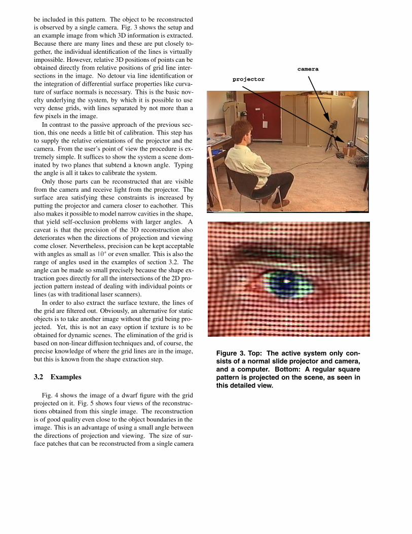
be included in this pattern. The object to be reconstructedis observed by a single camera. Fig. 3 shows the setup andan example image from which 3D information is extracted.Because there are many lines and these are put closely to-gether, the individual identification of the lines is virtuallyimpossible. However, relative 3D positions of points can beobtained directly from relative positions of grid line inter-sections in the image. No detour via line identification orthe integration of differential surface properties like curva-ture of surface normals is necessary. This is the basic nov-elty underlying the system, by which it is possible to usevery dense grids, with lines separated by not more than afew pixels in the image.
In contrast to the passive approach of the previous sec-tion, this one needs a little bit of calibration. This step hasto supply the relative orientations of the projector and thecamera. From the user’s point of view the procedure is ex-tremely simple. It suffices to show the system a scene dom-inated by two planes that subtend a known angle. Typingthe angle is all it takes to calibrate the system.
Only those parts can be reconstructed that are visiblefrom the camera and receive light from the projector. Thesurface area satisfying these constraints is increased byputting the projector and camera closer to eachother. Thisalso makes it possible to model narrow cavities in the shape,that yield self-occlusion problems with larger angles. Acaveat is that the precision of the 3D reconstruction alsodeteriorates when the directions of projection and viewingcome closer. Nevertheless, precision can be kept acceptablewith angles as small as ��o or even smaller. This is also therange of angles used in the examples of section 3.2. Theangle can be made so small precisely because the shape ex-traction goes directly for all the intersections of the 2D pro-jection pattern instead of dealing with individual points orlines (as with traditional laser scanners).
In order to also extract the surface texture, the lines ofthe grid are filtered out. Obviously, an alternative for staticobjects is to take another image without the grid being pro-jected. Yet, this is not an easy option if texture is to beobtained for dynamic scenes. The elimination of the grid isbased on non-linear diffusion techniques and, of course, theprecise knowledge of where the grid lines are in the image,but this is known from the shape extraction step.
3.2 Examples
Fig. 4 shows the image of a dwarf figure with the gridprojected on it. Fig. 5 shows four views of the reconstruc-tions obtained from this single image. The reconstructionis of good quality even close to the object boundaries in theimage. This is an advantage of using a small angle betweenthe directions of projection and viewing. The size of sur-face patches that can be reconstructed from a single camera
projector
camera
Figure 3. Top: The active system only con-sists of a normal slide projector and camera,and a computer. Bottom: A regular squarepattern is projected on the scene, as seen inthis detailed view.

Figure 4. Image with grid for a dwarf figure.
Figure 5. Views of the 3D reconstruction ob-tained from fig. 4.
Figure 6. Four frames out of a video with facialexpressions.
position is maximised that way.Fig. 6 illustrates the capacity to capture dynamic 3D. It
shows 4 frames of a video of facial expressions. Through-out this sequence the grid was projected. Hence, for everyframe a 3D reconstruction could be made. For the moment,the reconstructions for the frames are still carried out in-dependently. This can be improved by the introduction oftemporal continuity. Fig. 7 shows reconstructions in a VRsetting. All images are composed of the face reconstruc-tion superimposed on a flat background (the backgroundis a simple video taken from an aquarium), and for someframes a virtual air bubble has been integrated. The globalhead motions, deformations, and changes in shading are allgenerated from the 3D reconstructions obtained from theinitial image sequence. In that sequence the head didn’t ro-tate and the illumination was fixed. The result is a little 3Dmovie.
Typical computation times for 3D shape are about 2 min-utes for a frame on an SGI Indigo, and about 1.5 minutes toadd texture if it has to be retrieved from the same image(i.e. with the pattern on). Undoubtedly, these times can be

Figure 7. Example of a dynamic 3D sequenceused for a short movie.
reduced further. The code can be optimised and also theexploitation of temporal continuity in time sequences is ex-pected to yield a substantial reduction in computation times.Nevertheless, it is clear that the system in its current formis far from real-time, i.e. cannot perform the reconstruc-tions at video rate. The data can be taken at such a rate, foroff-line reconstruction, but processing can’t keep up withdata acquisition. Currently, the software is being mappedonto hardware as to make it one or two orders of magnitudefaster.
4 Conclusions and future work
The basic thesis of this paper has been that new ap-plications of 3D modeling, i.c. the shift from metrol-ogy/inspection to visualisation/communications, calls fornew 3D acquisition techniques. Two examples were dis-cussed. The first is based on 3D reconstruction from uncali-brated video data. The second uses special illumination butstill requires little investment. A normal camera and projec-tor suffice. That system is also very simple to calibrate.
For the future our group plans several extensions of thiswork. For one thing, it is necessary to further streamline the3D reconstruction work of larger scenes. Secondly, work isplanned on the compression of 3D shapes and the efficientrepresentation of textures. Thirdly, it stands to reason tocombine several of such approaches into a single system,that fuses information from the different sources and letsone approach support the other.Acknowledgements: The authors gratefully acknowledgesupport of ACTS project AC074 ‘VANGUARD’ and IUAPproject ‘Imechs’, financed by the Belgian OSTC (Servicesof the Prime Minister, Belgian Federal Services for Scien-tific, Technical, and Cultural Affairs) Marc Proesmans andMarc Pollefeys thank the IWT (Flemish Institute for the Ad-vancement of Science in Industry) for support through theirresearch grants.
References
[1] Besl, P., Active Optical Range Imaging Sensors, MachineVision andApplications, Vol. 1, No. 2, pp.127-152, 1988
[2] K. Boyer and A. Kak, Color-encoded structured light for rapid ac-tive ranging, IEEE Trans. Pattern Anal. and Machine Intell., Vol. 9,No. 10, pp. 14-28, 1987
[3] G. Hu and G. Stockman, 3-D surface solution using structured lightand constraint propagation, IEEE Trans. Pattern Anal. and MachineIntell., Vol. 11, No. 4, pp. 390-402, 1989
[4] Jarvis, A persepctive on range finding techniques for computer vi-sion, IEEE Trans. on PAMI, Vol. 5, No 2, pp.122-139, 1983
[5] M. Maruyama, and S. Abe, Range Sensing by Projecting MultipleSlits with Random Cuts, IEEE PAMI 15(6), pp. 647-650, 1993.
[6] P. Vuylsteke and A. Oosterlinck, Range Image Acquisition with aSingle Binary-Encoded Light Pattern, IEEE PAMI 12(2), pp. 148-164, 1990.