3D Modeling of Wave-Seabed-Pipeline in Marine Environments · 3D Modeling of Wave-Seabed-Pipeline...
22
The Open Civil Engineering Journal, 2008, 2, 121-142 121 1874-1495/08 2008 Bentham Open Open Access 3D Modeling of Wave-Seabed-Pipeline in Marine Environments Behnam Shabani 1 and Dong-Sheng Jeng 2, * 1 Division of Civil Engineering, School of Engineering, University of Queensland, QLD 4072, Australia and 2 Division of Civil Engineering, School of Engineering, Physics and Mathematics, University of Dundee, Dundee, DD1 4HN, Scotland, UK Abstract: In this study, a three-dimensional numerical model is developed, based on the Finite Element Method, to ana- lyse the behaviour of soil under the wave loading. The pipeline is assumed to be rigid and anchored within a trench. The influence of wave obliquity on seabed responses, the pore pressure and soil stresses, are studied, which cannot be handled by the existing 2D models. It is revealed that three-dimensional characteristics systematically affect the distribution of soil response around the circumference of the underwater pipeline. Based on new 3D model, the effects of wave and soil char- acteristics and trench configuration on the wave-induced seabed instability are discussed in detail. INTRODUCTION Offshore pipelines are typically constructed as either un- derwater-laid or submarine-buried structures. From the de- sign-engineering point of view, these two categories of ma- rine pipelines are characterized by their different instability mechanisms and thus design procedures. Underwater-laid pipelines are mainly constructed in deep waters and laid on the seabed surface. In this category, the pipeline is subject to the instability due to the influence of presence of structure on its surrounding flow pattern, scouring near the pipeline, for- mation of free spans and the soil failure at span shoulders. This subject has been investigated by various researchers. Recently, the theory and literature of scouring around marine pipelines are outlined by Sumer and Fredsoe [1]. At the same time, underwater-laid pipelines are also found vulnerable to the liquefaction of underlying seabed soil layers. This issue, also, recently has attracted attention from researchers and pipeline engineers. Sumer et al. [2] and Teh [3] are the two recent contributions to the problem of the on-bottom stability of marine pipelines on liquefied seabeds. In shallow water, submarine pipelines are often buried within the seabed for the protection against human activities such as ship anchoring, dredging and fishing. In this region, ocean waves propagating over the seabed exert a significant dynamic pressure on the seabed soil. The porous seabed, therefore, undergoes consolidation under the wave loading. Considerable amounts of wave-associated pore pressure and stresses are consequently generated within the soil matrix. Such excessive pore pressure and the accompanied loss of soil effective stress will expose the seabed to the high poten- tial of liquefaction. At the same time, large wave-associated soil shear stresses will further impose the risk of seabed shear failure. The liquefied seabed near the pipeline provides the ground for the structure to sink or float within the bed due to its self-weight, while the shear failure instigates large horizontal movements of pipeline. It is also possible for the *Address correspondence to this author at the Division of Civil Engineering, School of Engineering, Physics and Mathematics, University of Dundee, Dundee, DD1 4HN, Scotland, UK; Email: [email protected] pipeline in a mobilized seabed to displace under strong bot- tom currents. Regardless of its pattern, a large pipeline de- formation is accompanied by considerable internal stresses within the structure; and thus may result in its failure. There- fore, it is crucial to gain a realistic understanding to wave- associated seabed behaviour near submarine buried pipe- lines, in order to enhance the safety of pipeline, reduce the risk of disruption in energy flow and prevent the economical and environmental hazards of pipe failure. Two well-known main mechanisms of soil instabilities are liquefaction and shear failure. The former is the loss of soil’s ability to withstand any normal or shear stress, while behaves as fluid [4]. The latter, is the soil loosing the ability to resist further shear stresses and thus, soil layers sliding on each other. To predict either phenomenon, wave-induced seabed responses, i.e. pore pressure, effective and normal stresses, should be evaluated and used in conjunction with appropriate soil instability criteria. Numerous studies have concentrated on the evaluation of seabed responses under wave loading [5-7]. However, the majority of them considered a two-dimensional wave-soil- pipeline interaction problem. These studies only deal with cases, in which the wave approaches normal to the orienta- tion of pipeline. However, in the real ocean environment, waves may approach the pipeline from any direction. There- fore, it is necessary to establish a three-dimensional model to study these circumstances and gain a realistic understanding of soil behaviour under an oblique wave loading. The pri- mary aim of this research is therefore to answer the question of “how significant are the three-dimensional effects on the wave-induced responses of seabed soil near a submarine buried pipeline?” Among available investigations, only two studies have addressed this problem from a three-dimensional point of view. The first study was the BIEM model of Lennon [8, 9], in which potential theory was applied to obtain the wave- induced pore pressure in the presence of a pipeline, while waves were considered to approach from multiple directions.
Transcript of 3D Modeling of Wave-Seabed-Pipeline in Marine Environments · 3D Modeling of Wave-Seabed-Pipeline...

The Open Civil Engineering Journal, 2008, 2, 121-142 121
1874-1495/08 2008 Bentham Open
Open Access
3D Modeling of Wave-Seabed-Pipeline in Marine Environments
Behnam Shabani1 and Dong-Sheng Jeng
2,*
1Division of Civil Engineering, School of Engineering, University of Queensland, QLD 4072, Australia and
2Division
of Civil Engineering, School of Engineering, Physics and Mathematics, University of Dundee, Dundee, DD1 4HN,
Scotland, UK
Abstract: In this study, a three-dimensional numerical model is developed, based on the Finite Element Method, to ana-
lyse the behaviour of soil under the wave loading. The pipeline is assumed to be rigid and anchored within a trench. The
influence of wave obliquity on seabed responses, the pore pressure and soil stresses, are studied, which cannot be handled
by the existing 2D models. It is revealed that three-dimensional characteristics systematically affect the distribution of soil
response around the circumference of the underwater pipeline. Based on new 3D model, the effects of wave and soil char-
acteristics and trench configuration on the wave-induced seabed instability are discussed in detail.
INTRODUCTION
Offshore pipelines are typically constructed as either un-derwater-laid or submarine-buried structures. From the de-sign-engineering point of view, these two categories of ma-rine pipelines are characterized by their different instability mechanisms and thus design procedures. Underwater-laid pipelines are mainly constructed in deep waters and laid on the seabed surface. In this category, the pipeline is subject to the instability due to the influence of presence of structure on its surrounding flow pattern, scouring near the pipeline, for-mation of free spans and the soil failure at span shoulders. This subject has been investigated by various researchers. Recently, the theory and literature of scouring around marine pipelines are outlined by Sumer and Fredsoe [1]. At the same time, underwater-laid pipelines are also found vulnerable to the liquefaction of underlying seabed soil layers. This issue, also, recently has attracted attention from researchers and pipeline engineers. Sumer et al. [2] and Teh [3] are the two recent contributions to the problem of the on-bottom stability of marine pipelines on liquefied seabeds.
In shallow water, submarine pipelines are often buried within the seabed for the protection against human activities such as ship anchoring, dredging and fishing. In this region, ocean waves propagating over the seabed exert a significant dynamic pressure on the seabed soil. The porous seabed, therefore, undergoes consolidation under the wave loading. Considerable amounts of wave-associated pore pressure and stresses are consequently generated within the soil matrix. Such excessive pore pressure and the accompanied loss of soil effective stress will expose the seabed to the high poten-tial of liquefaction. At the same time, large wave-associated soil shear stresses will further impose the risk of seabed shear failure. The liquefied seabed near the pipeline provides the ground for the structure to sink or float within the bed due to its self-weight, while the shear failure instigates large horizontal movements of pipeline. It is also possible for the
*Address correspondence to this author at the Division of Civil Engineering,
School of Engineering, Physics and Mathematics, University of Dundee,
Dundee, DD1 4HN, Scotland, UK; Email: [email protected]
pipeline in a mobilized seabed to displace under strong bot-tom currents. Regardless of its pattern, a large pipeline de-formation is accompanied by considerable internal stresses within the structure; and thus may result in its failure. There-fore, it is crucial to gain a realistic understanding to wave-associated seabed behaviour near submarine buried pipe-lines, in order to enhance the safety of pipeline, reduce the risk of disruption in energy flow and prevent the economical and environmental hazards of pipe failure.
Two well-known main mechanisms of soil instabilities
are liquefaction and shear failure. The former is the loss of
soil’s ability to withstand any normal or shear stress, while
behaves as fluid [4]. The latter, is the soil loosing the ability
to resist further shear stresses and thus, soil layers sliding on
each other. To predict either phenomenon, wave-induced
seabed responses, i.e. pore pressure, effective and normal
stresses, should be evaluated and used in conjunction with
appropriate soil instability criteria.
Numerous studies have concentrated on the evaluation of
seabed responses under wave loading [5-7]. However, the
majority of them considered a two-dimensional wave-soil-
pipeline interaction problem. These studies only deal with
cases, in which the wave approaches normal to the orienta-
tion of pipeline. However, in the real ocean environment,
waves may approach the pipeline from any direction. There-
fore, it is necessary to establish a three-dimensional model to
study these circumstances and gain a realistic understanding
of soil behaviour under an oblique wave loading. The pri-
mary aim of this research is therefore to answer the question
of “how significant are the three-dimensional effects on the
wave-induced responses of seabed soil near a submarine
buried pipeline?”
Among available investigations, only two studies have
addressed this problem from a three-dimensional point of
view. The first study was the BIEM model of Lennon [8, 9],
in which potential theory was applied to obtain the wave-
induced pore pressure in the presence of a pipeline, while
waves were considered to approach from multiple directions.

122 The Open Civil Engineering Journal, 2008, Volume 2 Shabani and Jeng
In fact, the potential theory is considered as being outdated,
since it does not provide a realistic prediction of wave-
induced seabed behaviour. Secondly, even if the potential
theory could be considered as applicable in a very limited
range of soils, it does not provide any information on soil
stresses. In other words, it is incapable of evaluating the po-
tential of soil instability near the pipeline.
In another study, Chen et al. [10] addressed a similar
problem by using the consolidation equations of Biot [11].
Although Biot theory is accepted as suitable for describing
the seabed behaviour under loading, Chen et al. [10] ques-
tionably concluded that there is no difference between two-
dimensional and three-dimensional cases. This conclusion is
found to be incorrect in the present study. It is possible that
such a conclusion is drawn based on the fact that Chen et al.
[10] only examined one set of wave/soil/pipe properties in
their research. Meanwhile, similar to Lennon [9], they also
did not investigate soil stresses. The present study, however,
reveals that the three-dimensional effects are significant par-
ticularly for soil normal and effective stresses. Therefore, the
current research is intended to study both wave-induced pore
pressure and stresses for a wide range of soil/pipe/wave
properties, using a 3-D model.
A rare number of two-dimensional studies such as Jeng
and Cheng [12] investigated the potential of wave-induced seabed shear failure in the presence of a buried pipeline.
However, to the author’s knowledge, even among two-
dimensional investigations, there is no study to systemati-cally investigate both shear failure and liquefaction near
submarine pipelines and over a wide range of wave/soil/pipe
properties. At the same time, no three-dimensional model is also available in the literature to address three-dimensional
effects on the potential of wave-induced shear failure and
liquefaction around buried pipelines. Therefore, seabed in-stabilities will also be systematically investigated in the pre-
sent study.
3D BOUNDARY VALUE PROBLEM
A submarine pipeline is considered to be buried within a trench as shown in the cross-sectional view in Fig. (1). As illustrated, the x- direction is perpendicular to the trench lat-eral walls; the y direction is parallel to the pipeline; and the z axis is assumed to be positive upward from the mud-line and located at the mid trench width. On the other hand, the plane view of the problem configuration is also plotted in Fig. (2). Ocean waves are assumed to propagate in the positive X- direction. Therefore an incident wave angle of is formed between the direction of wave progression (X- axis) and the pipe centreline (y- axis). For waves travelling parallel with the pipeline, thus, =0°, while for waves propagating normal to the pipeline, hence, =90°.
Governing Equations
The seabed soil surrounding a submarine buried pipeline consolidates under the dynamic pressure from ocean waves. Full three-dimensional Biot consolidation theory [11] is ap-plied in this study to evaluate the seabed response associated with the action of waves. The application of this theory is based upon the following assumptions of the seabed behav-iour:
Fig. (1). Definition sketch: cross-section of a trenched submarine
buried pipeline.
Fig. (2). Definition sketch: plan of progressive waves approaching a
trenched submarine buried pipeline.
• The Darcy law dominates the pore fluid flow through seabed voids.
• The soil skeleton is a linear elastic material and its be-haviour follows the Hooke’s law.
• Both the pore fluid and soil skeleton are compressible materials.
• Unsteady velocities, i.e. accelerations, in both pore fluid flow and soil skeleton displacements are assumed to be small and therefore negligible.
• The pore fluid is a uniform material consisting of pore water and air bubbles; and its properties such as the air content and the compressibility do not change during and as the result of the consolidation process.

3D Modeling of Wave-Seabed-Pipeline in Marine Environments The Open Civil Engineering Journal, 2008, Volume 2 123
• The seabed soil is hydraulically and structurally iso-tropic.
• The seabed material is uniform and homogenous.
Fig. (3) shows a small cubic element of consolidating seabed soil with shear and normal total stresses acting on it. The element is considered large enough compared with the size of pores so that it may be treated as homogenous, and at the same time small enough so it may be mathematically considered infinitesimal.
Fig. (3). Definition sketch: total stresses acting on a soil element.
The equilibrium state of stress, in the x-, y- and z- direc-tions respectively, requires:
x
x+
yx
y+ zx
z= 0 (1)
xy
x+
y
y+
zy
z= 0 (2)
xz
x+
yz
y+ z
z= 0 (3)
in which, ij is the soil shear stress acting in the j- direction and in the plane normal to the i- direction; i represents total normal stress in the i- direction. On the other hand, the sea-bed material is reported to be highly saturated with the de-gree of saturation ranging from about 0.90 to 1.00 as pointed out in Esrig and Kirby [13]. In such nearly saturated condi-tion, the relation between total and effective normal stresses of soil can be expressed, in any direction such as i-, as:
i = i p (4)
where, 'i is the normal effective stress in i- direction. It is
important to note that the relation (4) should be modified in
partially saturated soils.
Substituting equation (4) into equations (1)-(3), gives:
x
x+
yx
y+ zx
z=
p
x (5)
xy
x+
y
y+
zy
z=
p
y (6)
xz
x+
yz
y+ z
z=
p
z (7)
It is assumed that the soil skeleton is a linear elastic ma-terial. Therefore, stresses and strains in solid skeleton are related on the basis of Hooke’s law. That is:
xy = yx = G
u
y+
v
x (8)
xz = zx = G
u
z+
w
x (9)
yz = zy = G
v
z+
w
y (10)
x = 2G
u
x+
μ
1 2μ (11)
y = 2G
v
y+
μ
1 2μ (12)
z = 2G
w
z+
μ
1 2μ (13)
in which, G is the shear modulus of soil; μ is the Poisson’s ratio; u, v and w are soil displacements in x-, y- and z- direc-tions, respectively; and is the volumetric soil strain defined as:
=u
x+
v
y+
w
z (14)
Soil stresses, in relations (8) to (13), can be substituted into the equilibrium equations (5) to (7). This provides a system of partial differential equations for soil equilibrium in terms of soil displacements and the pore pressure:
G2u
x2+
2u
y2+
G
1 2μ x=
p
x (15)
G2v
x2+
2v
y2+
G
1 2μ y=
p
y (16)
G2w
x2+
2w
y2+
G
1 2μ z=
p
z (17)
Finally, based on conservation of mass, the storage equa-tion is used to describe the pore fluid flow:
k 2 p wn
p
t= w t
(18)
The system of equilibrium equations for the soil matrix in (15)-(17) and the storage equation in (18) is known as the quasi-static soil consolidation theory as well as the Biot con-
124 The Open Civil Engineering Journal, 2008, Volume 2 Shabani and Jeng
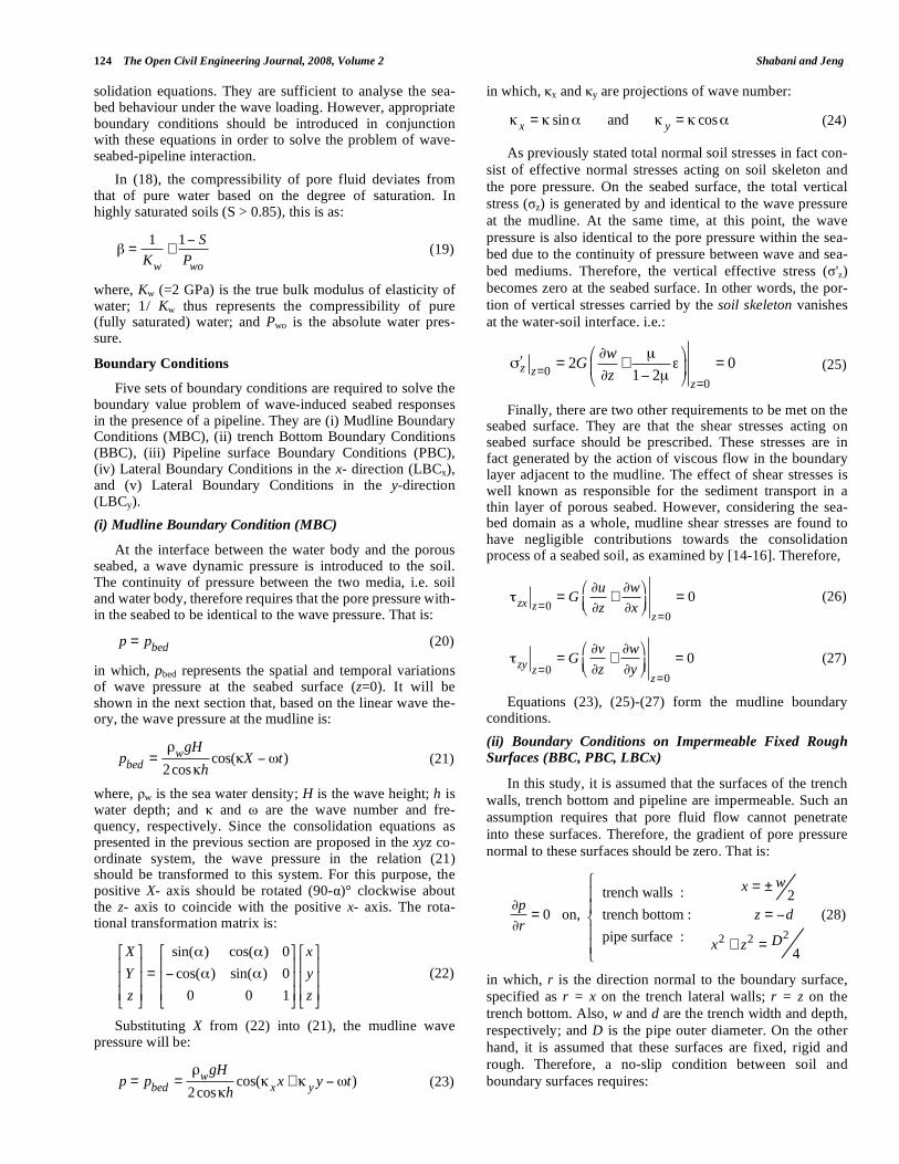
solidation equations. They are sufficient to analyse the sea-bed behaviour under the wave loading. However, appropriate boundary conditions should be introduced in conjunction with these equations in order to solve the problem of wave-seabed-pipeline interaction.
In (18), the compressibility of pore fluid deviates from that of pure water based on the degree of saturation. In highly saturated soils (S > 0.85), this is as:
=1
Kw
+1 S
Pwo
(19)
where, Kw (=2 GPa) is the true bulk modulus of elasticity of water; 1/ Kw thus represents the compressibility of pure (fully saturated) water; and Pwo is the absolute water pres-sure.
Boundary Conditions
Five sets of boundary conditions are required to solve the boundary value problem of wave-induced seabed responses in the presence of a pipeline. They are (i) Mudline Boundary Conditions (MBC), (ii) trench Bottom Boundary Conditions (BBC), (iii) Pipeline surface Boundary Conditions (PBC), (iv) Lateral Boundary Conditions in the x- direction (LBCx), and (v) Lateral Boundary Conditions in the y-direction (LBCy).
(i) Mudline Boundary Condition (MBC)
At the interface between the water body and the porous seabed, a wave dynamic pressure is introduced to the soil. The continuity of pressure between the two media, i.e. soil and water body, therefore requires that the pore pressure with-in the seabed to be identical to the wave pressure. That is:
p = pbed (20)
in which, pbed represents the spatial and temporal variations of wave pressure at the seabed surface (z=0). It will be shown in the next section that, based on the linear wave the-ory, the wave pressure at the mudline is:
pbed = wgH
2cos hcos( X t) (21)
where, w is the sea water density; H is the wave height; h is water depth; and and are the wave number and fre-quency, respectively. Since the consolidation equations as presented in the previous section are proposed in the xyz co-ordinate system, the wave pressure in the relation (21) should be transformed to this system. For this purpose, the positive X- axis should be rotated (90- )° clockwise about the z- axis to coincide with the positive x- axis. The rota-tional transformation matrix is:
X
Y
z
=
sin( ) cos( ) 0
cos( ) sin( ) 0
0 0 1
x
y
z
(22)
Substituting X from (22) into (21), the mudline wave pressure will be:
p = pbed = wgH
2cos hcos( x x + y y t) (23)
in which, x and y are projections of wave number:
x = sin and y = cos (24)
As previously stated total normal soil stresses in fact con-
sist of effective normal stresses acting on soil skeleton and
the pore pressure. On the seabed surface, the total vertical
stress ( z) is generated by and identical to the wave pressure
at the mudline. At the same time, at this point, the wave
pressure is also identical to the pore pressure within the sea-
bed due to the continuity of pressure between wave and sea-
bed mediums. Therefore, the vertical effective stress ( 'z)
becomes zero at the seabed surface. In other words, the por-
tion of vertical stresses carried by the soil skeleton vanishes
at the water-soil interface. i.e.:
00
2 01 2=
=
μ= + =
μz z
z
wG
z (25)
Finally, there are two other requirements to be met on the seabed surface. They are that the shear stresses acting on seabed surface should be prescribed. These stresses are in fact generated by the action of viscous flow in the boundary layer adjacent to the mudline. The effect of shear stresses is well known as responsible for the sediment transport in a thin layer of porous seabed. However, considering the sea-bed domain as a whole, mudline shear stresses are found to have negligible contributions towards the consolidation process of a seabed soil, as examined by [14-16]. Therefore,
zx z=0= G
u
z+
w
xz=0
= 0 (26)
zyz=0
= Gv
z+
w
yz=0
= 0 (27)
Equations (23), (25)-(27) form the mudline boundary conditions.
(ii) Boundary Conditions on Impermeable Fixed Rough
Surfaces (BBC, PBC, LBCx)
In this study, it is assumed that the surfaces of the trench
walls, trench bottom and pipeline are impermeable. Such an
assumption requires that pore fluid flow cannot penetrate
into these surfaces. Therefore, the gradient of pore pressure
normal to these surfaces should be zero. That is:
p
r= 0 on,
trench walls :
trench bottom :
pipe surface :
x = ± w2
z = d
x2 + z2 = D2
4
(28)
in which, r is the direction normal to the boundary surface,
specified as r = x on the trench lateral walls; r = z on the
trench bottom. Also, w and d are the trench width and depth,
respectively; and D is the pipe outer diameter. On the other
hand, it is assumed that these surfaces are fixed, rigid and
rough. Therefore, a no-slip condition between soil and
boundary surfaces requires:
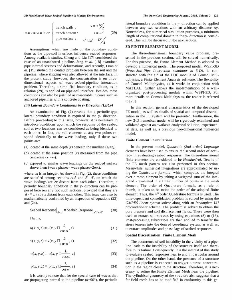
3D Modeling of Wave-Seabed-Pipeline in Marine Environments The Open Civil Engineering Journal, 2008, Volume 2 125
u = v = w = 0 on
trench walls :
trench bottom :
pipe surface :
x = ± w2
z = d
x2 + z2 = D2
4
(29)
Assumptions, which are made on the boundary condi-tions at the pipe-soil interface, influence seabed responses. Among available studies, Cheng and Liu [17] considered the case of an unanchored pipeline, Jeng et al. [18] examined pipe internal stresses and deformations, and recently, Luan et al. [19] studied the contact problem between the soil and the pipeline, where slipping was also allowed at the interface. In the present study, however, the concentration is on three-dimensional aspects of wave-seabed-pipeline interaction problem. Therefore, a simplified boundary condition, as in relation (29), is applied on pipe-soil interface. Besides, these conditions can also be justified as reasonable in cases such as anchored pipelines with a concrete coating.
(iii) Lateral Boundary Conditions in y- Direction (LBCy)
An examination of Fig. (2) reveals that a periodic-type lateral boundary condition is required in the y- direction. Before proceeding to this issue, however, it is necessary to introduce conditions upon which the response of the seabed soil at two locations can be considered as being identical to each other. In fact, the soil elements at any two points re-spond identically to the wave loading, only if these two points are:
(a) located at the same depth (z) beneath the mudline (z1=z2).
(b) located at the same position (x) measured from the pipe centreline (x1=x2).
(c) exposed to similar wave loadings on the seabed surface above them (wave phase1= wave phase2+2m ).
where, m is an integer. As shown in Fig. (2), these conditions are satisfied among sections A-A and A'- A', on which the wave loadings are 2 distant from each other. Therefore, a periodic boundary condition in the y- direction can be pro-posed between any two such sections, provided that they are
/ cosy L= distant from each other. This issue can also be mathematically confirmed by an inspection of equations (23) and (24).
Seabed Response
abcd= Seabed Response
a b c d (30)
That is,
u(x, y, z) = u(x, y +
L
cos, z) (31)
v(x, y, z) = v(x, y +
L
cos, z) (32)
w(x, y, z) = w(x, y +
L
cos, z) (33)
p(x, y, z) = p(x, y +
L
cos, z) (34)
It is worthy to note that for the special case of waves that are propagating normal to the pipeline ( =90°), the periodic
lateral boundary condition in the y- direction can be applied between any two sections with an arbitrary distance y. Nonetheless, for numerical simulation purposes, a minimum length of computational domain in the y- direction is consid-ered. This will be discussed in the next section.
3D FINITE ELEMENT MODEL
The three-dimensional boundary value problem, pre-
sented in the previous section, will be solved numerically.
For this purpose, the Finite Element Method is adopted to
develop a numerical model. The proposed model, WSPI-3D
(Wave-Soil-Pipe Interaction simulator in 3-D), is con-
structed with the aid of the PDE module of Comsol Mul-
tiphysics, a Finite Element Analysis software. The flexibility
of Comsol Multiphysics, as it works in conjunction with
MATLAB, further allows the implementation of a well-
organized post-processing module within WSPI-3D. For
more details on Comsol Multiphysics, the reader is referred
to [20].
In this section, general characteristics of the developed
FE model, as well as details of spatial and temporal discreti-
zation in the FE system will be presented. Furthermore, the
new 3-D numerical model will be rigorously examined and
validated against an available analytical solution, experimen-
tal data, as well as, a previous two-dimensional numerical
model.
Finite Element Formulations
In the present model, Quadratic (2nd order) Lagrange
elements have been used to ensure the second order of accu-
racy in evaluating seabed responses. The three-dimensional
finite elements are considered to be Hexahedral. Details of
the FE mesh pattern are also presented in this section.
Meanwhile, numerical integrations are approximated by us-
ing the Quadrature formula, which computes the integral
over a mesh element by taking a weighted sum of the inte-
grand - evaluated in a finite number of points in the mesh
element. The order of Quadrature formula, as a rule of
thumb, is taken to be twice the order of the adopted finite
element. Thus, the 4th
order Quadrature formula is used. The
time-dependant consolidation problem is solved by using the
GMRES linear system solver along with an Incomplete LU
preconditioner scheme. The problem is solved to obtain the
pore pressure and soil displacement fields. These were then
used to extract soil stresses by using equations (8) to (13).
Post-processing subroutines are then applied to transfer the
stress tensors into the desired coordinate system, as well as,
to extract amplitudes and phase lags of seabed responses.
Spatial Discretization: Finite Element Mesh
The occurrence of soil instability in the vicinity of a pipe-
line leads to the instability of the structure itself and there-fore to its failure. Consequently, it is the interest of this study
to evaluate seabed responses near to and in particular around
the pipeline. On the other hand, the presence of a structure such as a pipeline is expected to trigger a stress concentra-
tion in the region close to the structure. Therefore, it is nec-
essary to refine the Finite Element Mesh near the pipeline. The cylindrical geometry of the structure also suggests that a
far-field mesh has to be modified in conformity to this ge-

126 The Open Civil Engineering Journal, 2008, Volume 2 Shabani and Jeng
ometry, when it gets closer to the structure. In the region
near the pipeline, hence, a specific mesh pattern is consid-
ered herein as illustrated in Fig. (4). Some preliminary nu-merical results also suggest that it is sufficient for such a
specific pattern to spread to twice the pipe diameter, as is
shown. In fact, this is because of the concentration of stress, due to the presence of the structure, being likely to vanish
beyond this distance. On the other hand, the adopted pattern
allows the mesh to refine as it moves towards the structure.
Numerical experiments were carried out in this study to
determine the minimum required mesh resolution near the
pipeline that provides a desired accuracy for the evaluation
of wave-induced seabed responses. In the present study, such
a desired accuracy is defined as when numerical results con-
tain less than 1% of error in comparison with the exact solu-
tion. However, no exact solution is yet available for the re-
sponse of seabed soil in the presence of a pipeline. In this
regard, it is possible to consider a benchmark numerical so-
lution to act as the exact solution. For this purpose, bench-
mark numerical results should be obtained based on using an
extremely fine mesh.
The refinement of the introduced mesh pattern can be
controlled by a set of three parameters. They are: np showing
the number of mesh divisions around the pipeline perimeter;
nR representing the number of mesh divisions in the radial
direction on the pipe cross-section; nL standing for the num-
ber of mesh divisions over one wave length along the pipe
centreline, which coincides to the y- direction in Fig. (4).
Now, let us assume that the numerical results would fall on
the exact solution, when an extremely fine mesh, which is
generated by adopting np = 64, nR = 12 and nL = 40, is used.
This mesh refinement, therefore, corresponds to the bench-
mark numerical solution. It is worthy to note that this as-
sumption will be automatically confirmed upon the conver-
gence of coarse-mesh numerical results to the benchmark
solution. It is also assumed that the benchmark solution may
be achieved when FE Analysis is continued for up to five
wave periods (that is nc = 5) to ensure a fully stable numeri-
cal scheme. The benchmark FE time step ( t) is also consid-
ered as small as 1/90 of the wave period.
Fig. (4). Definition Sketch: 3-D Finite Element Mesh in the vicinity
of pipeline.
Table 1. Properties of Wave, Soil and Pipe Used in Numerical
Tests to Determine Required Mesh Refinement
Wave Properties
Water depth (h)
Wave period (T)
Wave height (H)
Wavelength (L)
Incident wave angle ( )
10 m
10 sec
2 m
92.32 m
0 or 90 degree
Soil properties
Shear stiffness (G)
Poisson’s ratio (μ)
Porosity (n)
Saturation (S)
Permeability (k)
5 MPa
0.33
0.40
98.5%
10-3 m/sec
Trench/pipeline properties
Trench width (w)
Trench depth (d)
Pipe diameter (D)
Pipe burial depth (B)
4 m
4 m
2 m
2 m
Hereafter, results from a set of numerical tests will be
presented. Tests are aimed at identifying the minimum mesh refinement that permits soil responses to fall within 1% of deviation from the defined benchmark solution. Properties of wave, soil and pipeline, which are used in numerical tests, are listed in Table (1) unless otherwise stated. In this section,
t = T/36 and nc = 2 are adopted to perform the FE analysis1.
It is essential for FEM modelling to examine the influ-
ence of mesh resolution on both the pore pressure and soil
stresses around the pipeline. For this purpose and as a meas-
ure of seabed responses around the structure, integrals of
pore pressure and soil stresses over the perimeter of pipe
cross-section will be studied. These are as
p
po
dsS�
,
'x
po
dsS�
,
p
po
dsS�
and
'z
po
dsS�
, in which s indicates the
circumference of pipe cross-section. In fact, it was also pos-
sible to individually study the effect of mesh resolution on a
number of points around the structure. However, using the
integrated form provides a general view of accuracy of the
model in evaluating the seabed behaviour around the pipe-
line as a whole. The wave dynamic pressure on seabed sur-
face oscillates periodically over a wave period and therefore
so does the integral of a seabed response. But, the amplitude
of this oscillation is used herein to justify the required mesh
refinement.
It is convenient to consider the case of ocean waves propagating normal to the pipeline ( =90°) to investigate the effect of mesh refinements in the xz plane, i.e. np and nR. The boundary value problem will be reduced to a two-dimensional soil consolidation problem under these circum-
1 It will be shown in the next section that t = T/36 and nc = 2 correspond to
an error of no more than one percent in numerical results and thus are
sufficient for the present study.

3D Modeling of Wave-Seabed-Pipeline in Marine Environments The Open Civil Engineering Journal, 2008, Volume 2 127
stances. Results of numerical simulations, presented in Tables (2) and (3), suggest that by the use of np = 32 and nR = 8 the deviation of integrated soil responses from the
Table 2. Seabed Responses Around Pipeline for Various
Mesh Refinements (np) while =90°; nR = 12; nL= n./a
pn
p
po
dsS� Deviation from Benchmark Solution
8
16
32
64
3.641
3.703
3.740
3.736
2.65%
0.99%
0.00%
0.11%
pn
'x
po
dsS�
Deviation from Benchmark solution
8
16
32
64
0.096
0.192
0.190
0.190
49.47%
1.05%
0.00%
0.00%
pn
'z
po
dsS�
Deviation from Benchmark solution
8
16
32
64
0.161
0.774
0.750
0.748
78.53%
3.20%
0.00%
0.27%
Table 3. Seabed Responses Around Pipeline for Various
Mesh Refinements (nR) while =90°; np = 32; nL = n./a
Rn
p
po
dsS�
Deviation from Benchmark Solution
4
6
8
10
12
3.729
3.737
3.744
3.711
3.740
0.29%
0.08%
0.11%
0.78%
0.00%
Rn
'x
po
dsS�
Deviation from Benchmark solution
4
6
8
10
12
0.198
0.193
0.192
0.190
0.190
4.22%
1.58%
1.05%
0.00%
0.00%
Rn
'z
po
dsS�
Deviation from Benchmark solution
4
6
8
10
12
0.743
0.747
0.751
0.750
0.750
0.93%
0.40%
0.13%
0.00%
0.00%
benchmark solution will be suppressed into less that 1%.
Therefore, it is sufficient to consider a finite element mesh,
which divides the pipeline circumference into 32 sections,
while it splits the radial direction into 8 segments. It is wor-
thy to mention that some investigations such as Magda [21]
also used a simplified two-dimensional version of mesh pat-
tern that is depicted in Fig. (4). However, Magda [21] only
examined the influence of mesh resolution on wave-induced
uplift forces acting on the pipeline. The uplift force is in fact
a measure of pore pressure around the circumference of
structure, as a whole. Nevertheless, the present tabulated
numerical results reveal that soil stresses would suffer from
much more significant errors, if a coarse mesh is inappropri-
ately used. Thus, the effect of mesh resolution on soil
stresses also has to be investigated.
To study the mesh refinement along the pipeline, i.e. nL, an ocean wave propagating parallel with the pipe orientation ( =0°) is considered. This is because under these circum-stances, the wave loading varies along the pipeline. There-fore, the number of mesh divisions along the structure is expected to influence the accuracy of numerical simulations. Table (4) clearly indicates that a refinement of nL = 20 per wave length is sufficient, for this dimension. It is, however, worthy to note that although nL = 20 keeps the deviation
Table 4. Seabed Responses Around Pipeline for Various
Mesh Refinements (nL) while =0°; np = 32; nR = 8
Ln
p
po
dsS�
Deviation from Benchmark solution
10
20
40
3.721
3.707
3.709
0.32%
0.05%
0.00%
Ln
'x
po
dsS�
Deviation from Benchmark solution
10
20
40
0.191
0.187
0.188
1.60%
0.53%
0.00%
Ln
'y
po
dsS�
Deviation from Benchmark solution
10
20
40
0.309
0.304
0.3095
1.32%
0.33%
0.00%
Ln
'z
po
dsS�
Deviation from Benchmark solution
10
20
40
0.746
0.735
0.736
1.36%
0.14%
0.00%
Ln Simulation time (hours)
10
20
40
1.6
16.0
52.0

128 The Open Civil Engineering Journal, 2008, Volume 2 Shabani and Jeng
from the benchmark solution below 1%, a simulation time of 16 hours is required to complete the numerical analysis. However, the case of nL = 10 despite slightly larger errors (maximum 1.60 %), requires only 1.6 hours to complete. Therefore, nL= 10 is recommended to be used when comput-ing facilities are limited.
Temporal Discretization
The finite element model developed in this study is time dependent. Therefore, it is essential to determine the maxi-mum allowed FE time step ( t). As mentioned previously, it is assumed that an exact solution may be achieved while t is adopted as low as 1/90 of a wave period. The objective of this section is to determine the FE time step so numerical errors are kept below 1% deviation from the exact solution. For this purpose, various time steps ranging from 1/9 to 1/90 of a wave period is examined hereafter. Simulation results are shown in Table (5). They demonstrate that a time step of
t = T/36 provides the sufficient numerical accuracy.
Table 5. Seabed Responses Around Pipeline for Various t
while =90°; np = 64; nR = 12; nL= n./a.; nc = 5
T
t
p
po
dsS�
Deviation from Benchmark solution
9
18
36
54
72
90
3.621
3.700
3.739
3.741
3.737
3.740
3.18%
1.07%
0.03%
0.03%
0.08%
0.00%
T
t
'x
po
dsS�
Deviation from Benchmark solution
9
18
36
54
72
90
0.189
0.190
0.190
0.190
0.190
0.190
0.53%
0.00%
0.00%
0.00%
0.00%
0.00%
T
t
'z
po
dsS�
Deviation from Benchmark solution
9
18
36
54
72
90
0.749
0.749
0.749
0.749
0.748
0.750
0.13%
0.13%
0.13%
0.13%
0.27%
0.00%
In general, the numerical analysis has to be continued for
several wave periods (cycles) to converge. The number of such cycles herein is represented by nc. While nc = 5 is con-sidered as the benchmark solution, Table (6) lists a series of experiments, in which values of nc between 1 to 5 have been tested. It is found that although the numerical scheme in the first cycle of calculations is largely unstable, from the second
cycle onward a persistent stability with the error of no more than 1% is observed. Therefore, numerical results throughout this section are extracted from the second cycle of the FE analysis.
Table 6. Seabed Responses Around Pipeline for nc while
=90°; np = 32; nR = 8; nL = n./a.; t= T/36
cn
p
po
dsS�
Deviation from Benchmark solution
1
2
3
4
5
3.846
3.736
3.733
3.737
3.739
2.83%
0.11%
0.19%
0.08%
0.03%
cn
'x
po
dsS�
Deviation from Benchmark solution
1
2
3
4
5
0.276
0.190
0.190
0.190
0.190
45.26%
0.00%
0.00%
0.00%
0.00%
cn
'z
po
dsS�
Deviation from Benchmark solution
1
2
3
4
5
1.240
0.748
0.750
0.749
0.749
65.33%
0.27%
0.00%
0.13%
0.13%
VALIDATION
Since the three-dimensional Finite Element model devel-
oped in the present study is new, it is necessary to validate
the present model before proceeding to apply it to the 3-D
wave-soil-pipeline interaction problem. For this purpose, a
possible option is to consider the simplified case of the
wave-induced response of a seabed in the absence of a struc-
ture. The exact solution for the interaction between a pro-
gressive wave and the naked seabed has been proposed by Hsu and Jeng [22].
It should be noted that the presented solution is for the case in which the seabed soil is not confined within a trench. Therefore, the numerical model should be modified so that the lateral trench wall boundary conditions in the x- direction presented previously would be replaced by a periodic boun-dary condition, while the length of computational domain (w) is considered as one wave length. Variations of ampli-tudes of soil responses over the seabed depth (z), obtained from the present numerical model as well as the exact solu-tion, are plotted in Fig. (5) for a set of soil and wave proper-ties. It is apparent that numerical results excellently coincide with the previous analytical solution [22].

3D Modeling of Wave-Seabed-Pipeline in Marine Environments The Open Civil Engineering Journal, 2008, Volume 2 129
Fig. (5). Verification of numerical simulations from the present
model against the analytical solution of Hsu and Jeng [22] for the
wave-induced response of a seabed without a structure.
This is the numerical model developed to investigate the influence of wave angle of incidence on seabed responses near a submarine buried pipeline. Hence, it is essential to examine the performance of this model in a seabed with the presence of a pipeline. Although numerous investigations have applied the potential theory to derive an analytical solu-tion for the problem of wave-seabed-pipe interaction, no exact solution using Biot consolidation theory is yet avail-able in the literature even for a simplified two-dimensional case. On the other hand, to the author’s knowledge no ex-perimental investigation has been carried out to consider three-dimensional influences. Therefore, it may be beneficial to verify numerical results against experimental data for the seabed response around a pipeline under the action of waves propagating normal to the structure. Such a simplified two-dimensional case has been experimentally studied in [23, 24], among others. Results presented in Sudhan et al. [24] appear to be extremely scattered. Therefore, experimental data from Turcotte et al. [23] is used herein to validate the numerical model.
Turcotte et al. [23] carried out a series of seven tests in Joseph H. DeFrees Hydraulics Laboratory, Cornell Univer-sity. Experiments covered a range of short to long waves with a constant water depth. Seabed bed materials also re-mained unchanged over tests. Experiments were performed in a 17 m long, 0.76 m wide wave tank, where a 0.168 m PVC pipe was buried in trenched sand. Eight pore pressure transducers were instrumented around pipe circumference at every 45 degrees. The authors reported contours of pore pressure amplitudes in the vicinity of pipeline. Among the tested wave lengths, three cases representing short, interme-diate and long waves have been adopted herein for the com-parison between numerical and experimental data. Figs. (6)-(8) show pore pressure amplitudes, corresponding to these
three wave lengths, around the pipeline circumference. Soil, pipe and wave properties are also indicated on these figures.
Fig. (6). Verification of numerical simulations from the present
model against experimental data in Turcotte et al. [23] for short
wave lengths.
Fig. (7). Verification of numerical simulations from the present
model against experimental data in Turcotte et al. [23] for interme-
diate wave lengths.
Details of the Finite Element Model applied to simulate wave-soil-pipe interaction are presented in this section. Nu-merical experiments to justify the minimum required mesh resolution are performed. Further, the desired temporal dis-cretization of time dependant FEA is examined. This was followed by a series of tests to validate the proposed numeri-cal model. This included the verification of numerical results against an available analytical solution for the case of wave-induced seabed responses in the absence of a structure, as well as the comparison between numerical results and data from wave tank experiments of Cornell University. The lat-ter covers the two-dimensional case of wave-seabed-pipeline interaction with waves approaching normal to the pipeline orientation. In both cases, excellent agreement was achieved. It was also found that the numerical model matches the ex-

130 The Open Civil Engineering Journal, 2008, Volume 2 Shabani and Jeng
perimental data better, when water waves are longer. The present three-dimensional model was also compared with an existing two-dimensional model. The 2-D model was found to be outperformed by the current model. In the next section, the proposed model will be used for a thorough parametric study on wave-induced seabed behaviour around pipelines, including the three-dimensional effects.
Fig. (8). Verification of numerical simulations from the present
model against experimental data in Turcotte et al. [23] for long
wave lengths.
SEABED INSTABILITIES
Wave-Induced Shear Failure
Seabed soil failure, due to shear stresses, in the region close to the pipeline has been recognised as one of main mechanisms that will lead to the pipeline instability. In fact, the shear failure is the loss of soil ability to resist against shear stresses. This phenomenon is accompanied by the slid-ing of soil layers on each other and thus often by large hori-zontal displacements in the seabed deposit. The submarine pipeline, buried in the failed soil region, consequently un-dergoes large deformations and internal stresses, which in turn triggers the failure of the structure. Therefore, it is nec-essary to study the phenomenon of soil shear failure in the vicinity of a submarine pipeline. To date, several criteria have been proposed in the literature to justify the occurrence of soil shear failure. Among them, the Mohr-Coulomb shear failure criterion has been widely used by engineers in vari-ous geotechnical engineering applications. Thus, this crite-rion is adopted in the present study to investigate the soil instability as the result of excessive wave-induced shear stresses. Herein, a brief description on the Mohr-Coulomb criterion is presented.
Seabed stresses introduced and evaluated in previous sec-tions were only due to the dynamic action of ocean wave pressure. However, the seabed soil is also under a static load-ing from its self-weight. It is important to note that soil in-stabilities are dominated by absolute seabed responses, which are formed by the superposition of static and dynamic (wave-induced) components of soil stresses. Therefore, it is essential to formulate absolute soil stresses before proceed-ing to describe the shear failure criterion. Considering a soil
element located at the elevation z below the seabed surface, the state of static overburden effective stresses induced by the buoyant weight of soil column above this element is il-lustrated in Fig. (45b). Soil overburden effective stresses are, therefore, as:
ox = oy = Ko sz = K
o( s w )z (35)
oz = sz = ( s w )z (36)
where, ox ,
oy and oz are static normal effective
stresses in the x-, y-, and z- directions, respectively; 's is the
submerged unit weight of the soil, s and w are unit weights
of soil and water, respectively; and Ko is the coefficient of
earth lateral pressure. As throughout this text, a negative
value represents a compressive stress mode. It is also worthy
to point out that the soil self-weight imposes no shear
stresses in the x-, y-, and z- planes on the soil element. Fi-
nally, absolute soil stresses are:
x = x + Ko( s w )z (37)
y = y + Ko( s w )z (38)
z = z + ( s w )z (39)
Absolute x, y- and z- effective stresses can further be
used to obtain absolute principal effective stresses though the
same methodology as described by equations (35)-(36).
To describe the shear failure criterion, let us assume an
arbitrary plane within the soil element, normal to which an
absolute effective stress of is acting in the compressive
mode. At the same time, the maximum absolute shear stress
that acts within this plane is assumed to be represented by .
According to Coulomb’s criterion, the shear stress that
brings the soil to the state of shear failure ( f ) is related
by:
f = tan f( ) (40)
in which, f is the soil internal friction angle, which is a
property of seabed soil. The shear failure occurs if the abso-
lute soil shear stress exceeds f . By defining the stress angle
( ), with analogy to the equation (40), as the ratio of abso-
lute shear stress to the absolute normal effective stress, the
shear failure criterion can be expressed by:
f (41)
On the other hand, the state of soil stress on any arbitrary
plane falls within the region confined by three-dimensional
Mohr circles. Therefore, the utmost stress angle for a given
state of soil stress is limited to the slope of a line that is tan-
gent to the greatest of Mohr circles, as plotted in Fig. (9).
The stress angle is therefore:
= sin 1 33 11
11 + 33
(42)

3D Modeling of Wave-Seabed-Pipeline in Marine Environments The Open Civil Engineering Journal, 2008, Volume 2 131
where, 11
and 33 are respectively major and minor abso-
lute principal effective stresses, as illustrated. Equations (41)
and (42) can be used to justify the occurrence of shear failure
in a seabed soil.
Fig. (9). The Mohr-Coulomb shear failure criterion.
Before proceeding to the next section, it is also useful to
explain to which extent static and dynamic components of
seabed loading contribute to the potential of soil shear fail-
ure. For this purpose, consider a soil element within the sea-
bed without the presence of wave dynamic loading. Since,
there are no shear stresses acting on surfaces of this soil ele-
ment, ox ,
oy and oz , also serve as principal effective
stresses under the static loading. Substituting these stresses
into the equation (42), the at-rest stress angle corresponding
to the initial geostatic state of soil stresses may be defined
and simplified as:
o
= sin 1 oz ox
oz + ox
= sin 1 1 Ko
1+ Ko
(43)
On the other hand, the soil coefficient of lateral earth pressure can be related to the internal friction angle by the formula proposed by Jacky (1944):
K
o= 1 sin f( ) (44)
Substituting equation (44) into (43), one will get:
sin o =sin f
2 sin f
(45)
Polous [25] reported that the internal friction angle of a sandy seabed ranges from 20° to 30° [26]. In this range, it is possible to accurately fit a linear relation into the equation (45). However, let us approximate the equation (45) in 20°<
f <30° by a simpler linear relation, which is of unit slope:
o = f C (46)
where, C is a constant that can be considered to be around
9.5° (see Fig. (10)). Inspired by the relation (46), it is then
possible to define a wave-induced perturbation in soil stress
angle such as ( )wave= - o. Such wave-associated perturba-
tion is therefore able to bring the soil from the state of geo-
static stresses into the shear failure, if it is as large as C =
( )critical= 9.5°. This approach may be useful to gauge how
significantly soil, wave and trench properties can influence
the potential of seabed shear failure. In fact, a parameter may
be justified as being influential, if it helps the wave-induced
stress angle to change considerably towards the critical value
of 9.5°. It is for the first time that the concept of wave-
induced perturbation of stress angle is introduced to the lit-
erature. This concept is used as an indicative along with nu-
merical results from the three-dimensional FEM model that
are calculated directly based on equation (42).
Fig. (10). Linear approximation of relation between geostatic stress
angle and internal friction angle.
It should be pointed out that, as it will be shown later, the
stress angle perturbation often alters much beyond the value
of 9.5 degrees as the result of a change in water wave proper-
ties. In fact, a small change in wave characteristics can be so
influential in altering the sate of soil stresses from the com-
pressive to the tensile mode. In contrary, soil properties are
often found to produce much smaller effects on perturbations
of stress angle. However, the influence of most soil proper-
ties is still comparable with 9.5 degrees. Therefore, both soil
and wave properties will be considered in this research to
carry out a parametric study on the stress angle. More details of the parametric study will be presented in coming sections.
Wave-Induced Soil Liquefaction
Another important mechanism for the instability of sub-marine buried pipelines is the seabed liquefaction. The lique-faction, as defined in [27], is the transformation of a granular material from a solid to a liquefied state as a consequence of increase in pore water pressure and reduction in compressive effective stress [28, 29]. In fact, a wave-induced increase in pore pressure can be strong enough to cause the effective stress to vanish or even go into the tensile mode. This is trig-gered by the loss of grain to grain contacts in the soil matrix and further results in the soil skeleton becoming incapable of carrying any external load, apart from its self-weight. Hence, a submarine pipe will sink or float within the liquefied sea-bed under the action of pipe buoyant weight. Large vertical

132 The Open Civil Engineering Journal, 2008, Volume 2 Shabani and Jeng
deformations and stresses that are associated with the sink-ing/floatation of a buried structure, finally, can lead to its failure. It is also possible for the pipeline to be dragged within the liquefied soil due to the presence of bottom cur-rents and thus to undergo large horizontal deformations. To avoid a catastrophe resulting from the pipeline failure, it is essential to investigate the potential of soil liquefaction in the vicinity of this structure. For this purpose, a reliable liq-uefaction criterion has to be applied.
Among available studies, researchers have considered various criteria to justify the occurrence of seabed soil lique-faction. Generally speaking, a first group of researchers has been concerned with the “reduction in effective stresses” as the liquefaction criterion. Among those, Okusa [30] sug-gested that a sandy bed becomes liquefied if the absolute vertical effective stress steps into the tensile (positive) phase. That is:
z 0 (47)
It should be pointed out that seabed effective stresses are initially in the compressive mode under-calm sea conditions as the result of the weight of overlaying soil layers. There-fore, substituting the absolute vertical effective stress from equation (39), the aforementioned liquefaction criterion be-comes as:
z + s w( ) z 0 (48)
Later, Tsai [31] modified this criterion by considering the average of absolute effective stresses, as:
1
3 x + y + z( )
=1
3 x + y + z( ) +1+ 2K
o
3 s w( ) z 0
(49)
A common property of the work Okusa [30] and Tsai [31] is the use of effective stresses. However, the fieldwork by Zen and Yamazaki [32] revealed that field measurements of soil effective stresses involve significant inaccuracies, when the soil is near to the liquefaction state. Therefore, they suggested the use of a liquefaction criterion based on the excess pore pressure. In fact, Zen and Yamazaki [33] applied the underlying assumptions of one-dimensional consolida-tion theory to replace the change of vertical effective stress from the geostatic state to the absolute value (i.e. wave-associated vertical effective stress) by the excess pore pres-sure. Hence, the equation (48) was approximated by the fol-lowing criterion:
z pexcess + s w( ) z 0 (50)
where, the excess pore pressure is:
pexcess = p pbed (51)
The advantage of this method is the use of wave-induced pore pressure, which is found to be reliably measured even in nearly liquefied soils. Later, Jeng [34] extended this ap-proximate framework to three-dimensions with an analogy to the equation (49). They have also shown that their liquefac-tion criterion, formulated in equation (52), reproduces field observations of Zen and Yamazaki [32] better than other
aforementioned criteria. Therefore, this criterion is adopted in the present study to justify the occurrence of seabed lique-faction in the vicinity of submarine buried pipelines.
pexcess +
1
31+ 2K
o( ) s w( ) z 0 (52)
The adopted liquefaction criterion is shown in Fig. (11)
for the case of a naked seabed in the absence of a pipeline.
As it is illustrated, the excess pore pressure becomes positive
in seabed under the wave trough. This is because the wave
dynamic pressure (pbed) is attenuated within the porous bed
and the wave-induced pore pressure (p) is, therefore, a frac-
tion of wave pressure. Hence, under the wave trough, where
the pressure is in suction (negative) mode, pexcess = p- pbed is
positive. However, it should be pointed out that this illustra-
tion is an indicative idealized case. In reality, where a phase
lag also exists between the pore pressure and the seabed
loading, a positive excess pore pressure can be observed dis-
tant from the wave trough. In particular, such a phase lag can
be extremely significant when the structure exists. The soil
liquefaction occurs under stormy conditions when the excess
pore pressure exceeds the compressive mean geostatic stress,
which is linearly increasing over the seabed depth. There-
fore, a liquefied state of soil is observed in a layer immedi-
ately below the seabed surface, as indicated. It should be
noted that the seabed surface may be always considered to be
liquefied.
Fig. (11). The concept of wave-induced liquefaction after Zen and
Yamazaki [33].
PARAMETRIC STUDY
In this section, a parametric study on seabed instabilities is proposed with an analogy to the parametric study previ-ously carried on wave-induced seabed responses. For this purpose, potentials of soil liquefaction and shear failure around a pipeline are studied. The excess pore pressure and the stress angle are respectively considered as indicators of liquefaction and shear failure potentials and successively

3D Modeling of Wave-Seabed-Pipeline in Marine Environments The Open Civil Engineering Journal, 2008, Volume 2 133
investigated in conjunction with their critical limits that were previously introduced in relations (52) and (41). Influences of wave obliquity, soil properties, trench/pipeline geometries and water wave characteristics on the excess pore pressure and stress angle are thoroughly studied using the developed three-dimensional numerical model. It should be emphasised that a detailed study on seabed instabilities around submarine pipelines was not previously available in the literature even using two-dimensional models.
Finally, since the wave-loading is of a periodic nature both in time and space, both the stress angle and excess pres-sure also follow similar periodic patterns. Nevertheless, it will be shown that spatial and temporal distributions of these variables are not simply sinusoidal. Therefore, such distribu-tions will be discussed prior to going further into the para-metric study. From that point onward, amplitudes of the stress angle and excess pore pressure will be the subject of parametric study. It is worthy of note that peak or the most critical values of these parameters over a wave period is re-ferred to by the term amplitude, in this text.
Three-Dimensionalities of Ocean Waves
One of the key objectives of developing the three-dimensional finite element model is to determine the influ-ence of wave obliquity on the potential of seabed instability near the pipeline. No study is yet available in the literature to address such effects. On the other hand, the occurrence of liquefaction and shear failure are respectively justified based on the wave-induced excess pore pressure (pexcess) and the stress angle ( ) within the seabed soil. Hence, variations of these parameters with the wave direction ( ) are investigated in this section.
Fig. (12). The distribution of stress angle for a point located on the
pipe perimeter at =135° (a) over a pipeline span axis, when t=T
(see the upper horizontal axis: yy), (b) over a wave period, when
y=0 (see the lower horizontal axis: t).
As discussed earlier, the wave obliquity affects seabed responses through the following mechanisms: (1) three-dimensional geometry-based influences and (2) effects of wave direction on the amplitude of seabed responses. The former requires variations of pore pressure and soil stresses to be periodic over spans of the length L/cos( ) along the pipe longitudinal axis, as well as, over the wave period. In the same manner, key parameters to justify the potential of
soil instabilities, pexcess and , would not be an exception. In particular for the stress angle, however, the spatial and tem-poral distribution, though being periodic, is not linearly sinu-soidal, as illustrated in Fig. (12). The complex distribution pattern of stress angle, nevertheless, is of little or no impor-tance, since it is the peak value of stress angle | |, which is the key factor to evaluate the risk associated with the shear failure. This peak value is referred to as the amplitude of stress angle, throughout this text.
On the other hand, it is vital to coastal geotechnical engi-neers to determine influences of wave direction on the so-called amplitude of stress angle | | and excess pore pressure |pexcess|. Fig. (13) shows the distribution of | | around the pipeline circumference for various wave obliquities. It is evident that sheltered and naked sides of a pipeline behave symmetrically when ocean waves are propagating parallel with the pipeline ( =0°). That is = 90° and 270° serve as axes of symmetry for the illustrated distribution pattern (see filled circles). The symmetric behaviour, however, is not applicable when the pipe is exposed to an oblique wave. The obliquity-induced asymmetry is more significant at the lower half of the pipe perimeter (180° < < 360°). In the presented example, the amplitude of the stress angle is found to vary mainly monotonically with , in each of the circumferential spans formed between the six illustrated inversion nodes/ regions. The direction of this monotonic trend reveres among adjacent circumferential spans.
Fig. (13). The distribution of stress angle amplitude (| |) around
pipe circumference for various wave directions (soil, wave and pipe
properties are as in Fig. (12)).
A wide range of wave, soil and trench properties has
been investigated in this study and numerical results have
shown that the obliquity-induced asymmetry of stress angle
remains a characteristic feature for all cases. However,
monotonic variations of stress angle with the wave direction
have been observed exclusively in highly permeable, very
loose, and highly saturated soils. Due to this complex behav-
iour, a possible way to justify how significant influences of
wave obliquity are, is to consider the largest stress angle that
could be ever experienced around a pipeline. This is because
it is important for pipeline engineers to avoid the occurrence
of shear failure at any point over the pipe circumference. In

134 The Open Civil Engineering Journal, 2008, Volume 2 Shabani and Jeng
this regard, Table (7) presents the maximum value of stress
angle over the pipeline perimeter ( max), for several simu-
lated cases. In this table, the value of max corresponding to
waves propagating parallel with and normal to the pipeline
are respectively shown by max
0 and max
90 ; meanwhile max
cr
stands for the most critical value of stress angle that a wave
of an arbitrary direction can generate; finally, cr is the
wave direction, for which max
cr is observed. It should be
noted that for some cases max
cr can be more than 30° larger
than max
90 , which represents a two-dimensional case (see
last row of table). At the same time, although other cases
show much smaller difference, it should be still remembered
from the previous section that the soil will fail if the waves
could increase the stress angle only about 9.5 degrees. There-
fore, any three-dimensional effect that can boost up the stress
angle even a few degrees can still be considered as being
significant. On the other hand, an inspection into values of
cr in the table shows that the two limiting cases of = 0°
or 90° are not always responsible for the most critical situa-
tion.
Table (7). The maximum of stress angle ( max) experienced
around pipeline for a variety of soil and wave prop-
erties (unless explicitly expressed within the table,
soil, wave and pipe properties are as h=25 m, T=8.36
s, L=100 m, G=106 Pa, μ=0.4, n=0.3, k=10
-3 m/s,
S=0.97, D=1.0 m, w/D=4.0, d/D=2.0, B/d=0.5, Ko=0.5,
s=1.969 w and H=5.0 m).
Soil/wave Properties 0max
90max max
cr cr
G=0.1Mpa 24.8 26.6 26.7 67.5
G=100Mpa 32.2 32.7 32.8 45.5
k=10-4 m/s 28.4 29.0 29.0 90.0
k=10-1 m/s 24.8 26.7 26.8 67.0
S=91% 40.1 41.2 41.2 90.0
S=99% 25.4 27.2 27.2 90.0
T=12 sec, h=12.5 m 59.6 53.4 60.1 22.5
T=10 sec, h=12.1 m 72.6 57.4 90.0 22.5
Fig. (14) illustrates that the influence of wave direction
on the amplitude of excess pore pressure is not significant. Consequently, the potential of complete liquefaction is likely to remain unchanged even when the waves are approaching the pipeline from an oblique angle. Therefore, unlike the potential of shear failure, a two-dimensional model is suffi-cient to justify the occurrence of complete liquefaction around the pipeline. However, the amplitude of pexcess, which can be obtained from a 2-D simulation, should be considered along with the three-dimensional geometry-based influences of wave obliquity on the spatial distribution of soil re-sponses, as previously discussed.
Fig. (14). The distribution of amplitude of wave-induced excess
pore pressure (|pexcess|/po) around pipe circumference for various
wave directions.
Influences of Seabed Soil Properties
Modulus of Soil Shear Stiffness
The influence of soil shear stiffness on the pore pressure and soil stresses has been studied earlier in this section. In fact, the shear modulus was found to have significant effects on the wave-associated momentary seabed behaviour. There-fore, it is essential to also examine the influence of this pa-rameter on the potential of seabed soil instabilities. As plot-ted in Figs. (15),(16), amplitudes of both excess pore pres-sure and stress angle increase when the seabed material is stiffer. Therefore, a stiff porous bed is more vulnerable to both complete liquefaction and shear failure.
Fig. (15). The distribution of |pexcess|/po around pipe perimeter for
various G. (Ko=0.5, s=1.969 w, H=5.0 m).
To determine the critical value of excess pore pressure, corresponding to the onset of soil liquefaction, it is possible to normalize the relation (52) by the amplitude of mudline pressure. Hence, the seabed will be liquefied if the non-dimensional excess pore pressure exceeds the critical value:

3D Modeling of Wave-Seabed-Pipeline in Marine Environments The Open Civil Engineering Journal, 2008, Volume 2 135
pcr
po
=1+ 2K
o( ) s w( )3p
o
z = z (53)
where, is a coefficient which is a function of lateral earth pressure coefficient, soil and water unit weights and the am-plitude of mud-line pressure.
Fig. (16). The distribution of | | around pipe circumference for
various G (Ko=0.5, s=1.969 w, H=5.0 m).
The normalized critical excess pore pressure varies over the pipeline circumference, since so does the vertical coordi-nate z. It should be pointed out that in the evaluation of criti-cal excess pore pressure, the pipe cross-section is assumed to be of an equivalent unit weight similar to that of porous bed. In fact, this assumption is reasonable for the typical range of materials and diameters used for the construction of under-water pipelines, as well as, for fluids usually being trans-ported though a submarine pipe. In this parametric study, the coefficient of lateral earth pressure of Ko = 0.5, and soil unit weight of s = 1.969 w are often used to evaluate the critical excess pore pressure. This unit weight is the same as that observed in field measurements of Zen and Yamazaki [32]. A wave height of about H = 5 m is also often used, which may be considered as a stormy condition for the range of shallow water depths, in which the pipe burial is necessary. However, a non-breaking condition for water waves is still ensured. Although a variety of wave characteristics, i.e. wave length and wave period, could be chosen, for most cases the wave regime is deliberately chosen so the soil ini-tially remains well away from liquefaction. This will allow us to show a picture of soil/trench/pipe parameters that may be significant enough to cause a shift from this stable situa-tion to a liquefied state of soil.
In contrast to Fig. (15), where the excess pressure is still far below the critical value corresponding to = 0.60 (H =5.35 m), the stress angle in Fig. (16), is found to go beyond the soil internal friction angle. In fact, prior to exerting the wave loading, the stress lays at the value of o indicated on the graph. Considering the action of waves on a soil of G = 10
6 Pa, the stress angle still falls between its initial geostatic
value and the soil internal friction angle. However, by in-creasing the soil stiffness to G 10
7 Pa the soil will undergo
shear failure. Under these circumstances, the seabed at the
lateral sides of pipeline, in 0° < < 45°, 135° < < 225°, and 315° < < 360°, will fail. It should be pointed out that by using higher wave heights in numerical simulations, the unstable soil region around structure could even merge to cover the pipe crest as well. It is interesting to note that pat-terns of distributions of both excess pore pressure and stress angle remain alike for all examined soil shear moduli.
Soil Permeability
The range of permeability, often observed in marine sediments, was introduced in the earlier section. Several types of seabed material, with their permeabilities varying from k = 10
-4 m/s (fine sand) to k = 10
-1 m/s (gravel), have
been considered. Simulation results on the potential of soil liquefaction of different soil types, as plotted in Fig. (17), reveal that the amplitude of wave-induced excess pore pres-sure and thus the risk of soil liquefaction is considerably greater for fine marine sediments (k = 10
-3-10
-4 m/s). This
phenomenon is directly associated with the excessive damp-ing of mudline dynamic pressure inside a poorly-permeable bed, as demonstrated in Fig. (28) The risk associated with the liquefaction of gravel and other coarse sands is small and can be safely neglected under a typical storm. Similarly, finer materials also impose a higher potential of soil shear failure, as they are linked with larger stress angles such in Fig. (18). It should be noticed that although for the lowest permeability used herein the soil is not liquefied yet, the stress angle in similar conditions has already reached near to the shear failure limit.
Fig. (17) The distribution of |pexcess|/po around pipe perimeter for
various k.
On the other hand, the distribution pattern of excess pore pressure is found to remain the same for all cases. However, rather different behaviour patterns have been observed for stress angle in fine and coarse materials. In fact, maximum values of stress angle are located at the lower lateral sides of the pipeline, =190° and 350° for fine sediments, while points of high risk of shear failure are at the upper half of the pipe, =45° and 135°, in gravel and coarse sands.
The Degree of Saturation
It is common for most marine sediments to contain a small percentage of air, and thus showing a degree of satura-

136 The Open Civil Engineering Journal, 2008, Volume 2 Shabani and Jeng
tion between 0.90 and 1.00. However, even small amounts of air significantly reduce the compressibility of pore fluid and consequently influence seabed responses. Therefore, it is important to examine the effects of soil saturation on the instability of seabed soil, in the vicinity of a submarine bur-ied pipeline. For this purpose a range of nearly saturated soils has been adopted to carry out the parametric study. Fig. (19) demonstrates how significantly an increase in the soil air content will change the wave-associated excess pore pressure and the risk of complete liquefaction, compared with other soil characteristics previously studied. In addition to the critical value of excess pore pressure corresponding to a wave height of 5m, pcr corresponding to an exaggerated wave height of 8 m ( = 0.4) is also plotted in the figure. It can be seen that for S=91%, the excess pore pressure coin-cides with this critical value and thus the seabed liquefies.
Fig. (18). The distribution of | | around pipeline perimeter for vari-
ous k (Ko=0.5, s=1.969 w and H=5.0 m).
Fig. (19). Variations of |pexcess|/po with soil saturation.
As shown in Fig. (20), the soil stress angle also shifts up in less-saturated soils, with the 95% saturated sand being the first to show shear failure near the pipeline lateral sides. The failure region extends by further increasing the air content.
This continues so that for a 91% saturated soil, the stress angle at every point apart from the region below the pipeline, goes beyond the soil internal friction angle. It should be pointed out that, generally speaking, the seabed soil in the vicinity of the pipeline base at = 270° is often in the most stable situation, with the stress angle always remaining al-most unchanged due the action of waves.
Fig. (20). Variations of | | with soil saturation.
Influences of Trench and Pipeline Geometries
Trench Depth
Although the present numerical model is capable of
simulating any arbitrary trench geometry and pipe burial
depth, in the present parametric study the pipeline is as-
sumed to be buried halfway through the trench depth. There-
fore, by varying the trench depth, influences of both trench
depth and pipe burial depth are studied simultaneously. Such
an assumption is suitable for practical engineering purposes,
since due to the high cost of an underwater excavation, the
seabed will be trenched only as deep as to just comply with
the desired pipe burial depth. As illustrated in Fig. (21), the
amplitude of wave-associated excess pore pressure dramati-
cally increases in deeper trenches. This is because the mud-
line pressure is much attenuated in a deep trench, as dis-
cussed previously. However, in contrary to all previously
presented cases, an increase in the pore pressure may not be
immediately interpreted as a higher potential of complete
liquefaction. This seemingly surprising statement stems back
to the fact that while the pipeline is buried deeper within the
trench, geostatic overburden stresses around it and thus the
critical excess pore pressure will also increase. These
stresses are in fact a measure for the weight of the soil col-
umn above the pipeline and their action is to resist against
soil liquefaction as discussed while introducing the liquefac-
tion criterion. Under these circumstances, one way to study
the potential of seabed liquefaction is to normalize the ex-
cess pore pressure by its critical value.
A wave height and soil unit weight have been chosen so
that = 0.50 is used herein to evaluate the critical excess
pore pressure and to produce the plot of Fig. (22). Interesting
features can be interpreted from the presented results. That

3D Modeling of Wave-Seabed-Pipeline in Marine Environments The Open Civil Engineering Journal, 2008, Volume 2 137
is, moving from shallow burial depths (and trench depths) to
deep burial depths, the geostatic static stress gradually be-
come sufficient enough to overcome the increasing trend of
excess pore pressure. Hence, graphs of pexcess/pcr gradually
get closer to each other when increasing the burial depth.
This continues until d/D = 3.0, after which pexcess/pcr even
drops down by further increasing the burial depth. This fea-
ture implies that despite the traditional belief, increasing the
pipe burial depth does not always lead to a more secure pro-
tection against soil liquefaction. Instead, there exists a criti-
cal burial depth, after which an increase in pipeline stability
may be observed. However, a significant difficulty associ-
ated with this behaviour is that further increasing the burial
depth seems no longer economical, considering that even for
d/D = 3.5 the potential of liquefaction is still much more than
that for d/D = 1.50. Therefore, it may be beneficial to seek
other protection methods such as using a cover layer to pro-
tect the pipeline against soil liquefaction, rather than exces-
sively increasing the burial depth.
Fig. (21). The distribution of |pexcess|/po around pipeline circumfer-
ence for various d/D.
Fig. (22). The potential of soil liquefaction around pipeline circum-
ference for various d/D.
Another important feature of the results presented is that the most critical values of pexcess/pcr are always observed in the lower half of the pipeline. This means that in the case of an occurrence of soil instability, it is the soil at the lower half of pipeline that liquefies at the first place. However, the ex-cess pore pressure for the presented cases still merely reaches 35% of its critical value at the lower half of the pipe-line. On the other hand, the upper half of structure seems to be securely stable against liquefaction, especially when a trench is shallow. The significant difference between the potential of liquefaction at lower and upper parts of the pipe gradually vanishes in deeper trenches.
Despite the behaviour of liquefaction potential, the sub-marine pipeline is found to be more likely protected against shear failure, when buried in a deeper trench. This is the re-sult of stress angle decreasing almost everywhere around a pipeline when B and d are increased, as shown in Fig. (23). However, a more complicated relation between d and is observed near the pipe crest ( = 90).
Fig. (23). The distribution of | | around pipeline circumference for
various d/D.
(Soil, wave, trench and pipe properties are as in Fig. (22), Ko = 0.5, s = 1.969 w and H = 5.0 m)
Trench Width
A trench width ranging from 1.5 to 4.0 times of the pipe-
line diameter is investigated in this study. Amplitudes of
wave-associated excess pore pressure are plotted in Fig. (24). The illustration shows that values of non-dimensional excess
pore pressure decline by widening the trench geometry. The
influence of trench width slowly vanishes in wider trenches, where graphs of excess pore pressure gradually merge on
each other. However, the effect of trench breadth does not
completely diminish in the range of examined trench widths.
Fig. (25) illustrates the distribution of stress angle around the pipeline. The stress angle at the pipe bottom ( = 270°) is merely more than the static value, imposed by the soil sub-merged weight. On the other hand, the risk of shear failure is highest around = 35° and 145°, where the stress angle is just below the soil internal friction angle of seabed soil. Fur-thermore, widening the trench significantly increases the stress angle almost everywhere else around the pipeline.

138 The Open Civil Engineering Journal, 2008, Volume 2 Shabani and Jeng
However, a more complicated behaviour is observed near the potential shear failure regions, marked by A and B in Fig. (25), as the stress angle is the highest for w/D= 2.5.
Fig. (24). The distribution of |pexcess|/po around pipe perimeter for
various w/D.
Fig. (25). The distribution of | | around pipeline circumference for
various w/D.
Pipeline Diameter
The potential and pattern of soil liquefaction are expected to be different between pipelines of small and large diame-ters. To demonstrate this, Fig. (26) shows the distribution of excess pore pressure around a pipeline perimeter for various pipe diameters. In this regard, the upper and lower halves of the pipeline are found to behave in a different way. In fact, close to the crest of the structure, |pexcess|/po drops down by increasing the pipe diameter; while, an opposite trend is in the vicinity of the pipeline bottom. However, these results are not sufficient to justify how the potential of soil liquefac-tion varies with the pipe diameter. This is because by enlarg-ing D, geostatic overburden stresses will also drop at the upper half of the structure, while they will increase at its lower. Therefore, it is essential to examine the ratio between the excess pore pressure and its critical value.
Fig. (26). The distribution of |pexcess|/po around pipeline circumfer-ence for various pipe diameters.
Fig. (27). The potential of soil liquefaction around pipeline for
various pipeline diameters.
The distribution pattern of |pexcess|/pcr around the pipeline
is plotted in Fig. (27). |pexcess|/pcr is found to have a similar
behaviour as |pexcess|/po. This behaviour was in fact expected,
since generally speaking the pipeline is a slender structure.
Hence, a change in its diameter may not impose a significant
effect on “z” coordinates and thus “pcr = z” of points located
on its circumference.
Another feature of the potential of soil liquefaction near
the structure is that as the diameter decreases, a more uni-
form distribution of |pexcess|/pcr around the pipe perimeter is
observed. Therefore, in the event of soil instability, it is
likely for a slender pipeline to be completely surrounded by
liquefied soil. Consequently, a slender pipeline could sink or
float within the bed, depending on the magnitude of seepage
force and pipeline weight. However, the significant differ-
ence between |pexcess|/pcr at the lower and upper parts of a
large-diameter pipe requires extremely steep waves (i.e. a
large ) to liquefy the seabed at the pipe crest, while the pipe

3D Modeling of Wave-Seabed-Pipeline in Marine Environments The Open Civil Engineering Journal, 2008, Volume 2 139
bottom is capable of being liquefied much earlier. This un-
even liquefaction pattern allows the structure only to sink
within the bed, since the soil in the upper half of the struc-
ture may not be liquefied in most cases. However, strict
knowledge of all acting and reacting forces on the structure
is necessary to draw a strong conclusion. Further, the excess
pore pressure in the presented case is still far beyond the
critical liquefaction limit (pcr) for a storm of H = 5.35 m ( =
0.6), which was assumed to plot the Fig. (27).
Influences of Ocean Wave Properties
Wave Period
It has been previously shown in the earlier section that an increase in the wave period (T) forcefully shifts up the nor-malized wave-associated normal and shear stresses within the seabed soil. This effect has been attributed to the charac-teristic time required by the influence of mudline loading to penetrate into the seabed, in comparison with the period (frequency) of such a loading. It is important to examine the existence of a similar behaviour in the distribution of excess pore pressure around a pipeline. Therefore, several wave events of the same wave length (L = 100 m) but of variable frequency have been considered herein. These frequencies correspond to wave periods of 8.36 s to 14 s, which are common in the ocean environment. It is worth being re-minded that the wave dispersion equation requires wave events of longer periods to take place in shallower water depths. According to linear wave theory, therefore, the am-plitude of mudline pressure (po) is larger under these circum-stances. However, this effect is excluded from the parametric study on the excess pore pressure, when it is normalized by the amplitude of wave pressure at the mudline. Fig. (28) in-dicates that this normalized amplitude of excess pore pres-sure increases as does the wave period. The effect of T, how-ever, gradually fades away, as the excess pore pressure ratio goes beyond T = 12 s to 14 s. This phenomenon implies that loadings of period of more than 12 s can no longer be con-sidered as “quick” compared with the characteristic time that soil around the pipeline requires to adapt with the wave load-ing.
Fig. (28). The distribution of |pexcess|/po around pipe perimeter for
various T.
Once again, the occurrence of complete liquefaction around a pipeline, nevertheless, should be justified against non-dimensional geostatic overburden stresses. However, since pcr/po varies as the wave period changes, it is appropri-ate to examine pexcess/pcr to study the potential of soil lique-faction. As illustrated in Fig. (29), the lower part of the pipe-line (180° < < 360°) falls within the liquefied region for the wave period of 14 s and wave height of 5.0 m, since the excess pore pressure goes beyond its critical value (pcr). The increased potential of liquefaction in longer wave periods is mainly because of the fact that low frequency waves are as-sociated with excessively larger values of mudline loading.
Fig. (29). The potential of soil liquefaction around pipe perimeter
for various T. (Ko = 0.5 and s = 1.969 w).
Fig. (30). The distribution of | | around pipeline circumference for
various wave periods.
Unlike the potential of liquefaction, soil shear failure oc-curs around the pipeline even for much shorter wave periods. Referring to Fig. (30), a 5.0 m wave height triggers the soil shear failure in the upper part of the pipeline as well as most of its lower part, in wave periods of equal or greater than 10 seconds. Nonetheless, the seabed soil under the pipe base ( = 270°) interestingly remains strongly stable against shear failure, in all examined cases. It is important to note that a

140 The Open Civil Engineering Journal, 2008, Volume 2 Shabani and Jeng
stress angle ( ) between 0° and 90° portrays a Mohr circle with normal stresses completely being in a compressive phase. Meanwhile as increases by increasing T, the Mohr circle shifts towards the tensile phase. A Mohr circle with a tensile mode of stress on any plane is indicated by =90° in the present illustration. Knowing that sandy beds, which are non-cohesive, may not resist against a tensile stress, such a kind of instable situation is observed for T = 12 s and 14 s, as plotted.
Water Depth
Fig. (31) illustrates the influence of water depth on nor-malized amplitudes of wave-induced excess pore pressure. It should be pointed out that a decrease in water depth is asso-ciated with an increase in the amplitude of the mudline wave pressure (po). However, since the excess pore pressure, herein, is normalized by the amplitude of mudline pressure, this effect is not included in results presented in Fig. 68 In-stead, as discussed earlier in this section, as the wave enters shallower water depths, its wave length decreases. Thus, the geometry of wave loading on the seabed alters and thus the normalized excess pore pressure will be influenced. As illus-trated, the normalized excess pore pressure (|pexcess|/po) will increase as shallower water depths are chosen. Meanwhile, the unfortunate combination of increases in both |pexcess|/po and po for shallow water depths, results in the pipeline being extremely vulnerable to the soil liquefaction in shallow wa-ters, as can be deduced from Fig. (32). It is observed that for h = 5.38 m and H = 5 m, the |pexcess| exceeds the mean static overburden stress (pcr) everywhere in the lower half of pipe-line. Therefore, it is predicted that the soil in the vicinity of the lower part of the structure will be completely liquefied under this wave regime. At the same time, the threat for soil shear failure is even more substantial, since the stress angle in the upper half of the pipeline goes beyond the soil internal friction angle for all examined water depths, as depicted in Fig. (33). It should be pointed out that Mohr’s circles will shift into the tensile zone for both h =5.38 m h=7.61 m, as the stress angle reaches 90°. This is due to the mud-line dy-namic loading that becomes excessively large in shallow waters.
Fig. (31). The distribution of |pexcess|/po around pipeline circumfer-
ence for various water depths.
Fig. (32). The potential of soil liquefaction around pipe perimeter
for various h (Ko = 0.5 and s = 1.969 w).
Fig. (33). The distribution of | | around pipeline for various water
depths.
CONCLUSIONS
In this study, a three-dimensional numerical model for the wave-induced seabed response around a buried pipeline is proposed. Since there is no 3D experimental data avail-able, the present model is reduced to 2D case or the 3D case with absence of a pipeline. The comparison with the previ-ous theoretical and experimental work validated the present model.
Based on the newly 3D model, the effects of wave and soil characteristics on the wave-induced seabed instability, including shear failure and liquefaction, are discussed. Based on the parametric study presented, the following conclusions can be drawn:
(1) The concept of wave-induced perturbation of soil stress angle has been introduced for the first time in this study. It was found that the seabed undergoes shear failure when the soil stress angle increases 9.5 degrees from its geostatic value, due to the action of water waves.

3D Modeling of Wave-Seabed-Pipeline in Marine Environments The Open Civil Engineering Journal, 2008, Volume 2 141
(2) The wave obliquity influences the amplitudes of excess pore pressure and soil stresses in the same fashion as it acts on wave-induced pore pressure and principal stresses. The asymmetric distribution of potentials of seabed instabilities around a pipeline is the characteristic of an oblique wave system. However, the amplitudes of these potentials undergo a monotonic variation with wave obliquity only in highly-permeable, very loose and highly-saturated soils. As well, the stress angle around a submarine pipeline exposed to an oblique wave is ob-served to be up to 30 degrees larger than that in a two-dimensional system with waves approaching perpendicu-lar to the pipeline orientation. On the contrary, it is found sufficient to justify the potential for complete liquefac-tion near the structure by using a two-dimensional model, as the excess pore pressure is found not to be signifi-cantly affected by the wave direction.
(3) Generally speaking, an ordinary ocean storm may trigger a seabed shear failure, while the complete liquefaction of a soil is often observed only if ocean waves are too steep. On the other hand, the shear failure is often found to ini-tiate on the upper lateral sides of the pipe circumference, at 35° and 145°. The pipeline base is the most stable location against the shear failure with no significant per-turbation in the stress angle due to the action of waves. On the contrary, complete liquefaction is likely to be started at the lower half of a pipeline, while the upper half remains safe for most ordinary wave heights.
(4) Among various types of marine sediments, stiff, poorly-permeable, and soils with a low degree of saturation are most vulnerable to both types of seabed instabilities: shear failure and soil liquefaction. The degree of satura-tion is found to play the most influential role among other factors. This is due to the significant sensitivity of pore fluid compressibility to the amount of air bubbles in a seabed soil.
(5) The soil stress angle and so the risk of shear failure is higher in a wide and shallow trench. On the contrary, the wave-induced excess pore pressure is revealed to be con-siderably larger in a deep and narrow trench. In deep trenches, the behaviour of excess pore pressure, however, does not necessarily pose a higher potential of liquefac-tion. This is because the critical value of excess pore pressure corresponding to liquefaction near the pipeline will also increase as the structure is buried deeper. As a result, it has been observed that liquefaction potential in-creases as the trench is deepened up to 3.0 times the pipe diameter, after which geostatic stresses become sufficient enough to decrease the potential of soil liquefaction. Nevertheless, it may not be economical to excavate a trench with a depth of more than three times the pipe di-ameter. Therefore, it may be beneficial to bury the pipe-line in a shallow wide trench for protection against shear failure, while using other methods such as a cover layer on the seabed surface for pipeline protection against complete liquefaction.
(6) The most influential parameter on seabed instabilities are water wave properties, i.e. wave period, wave length and water depth. Any change in these parameters will cause a change in the mudline dynamic pressure, which is di-rectly proportional to the instability of the seabed soil.
REFERENCES
[1] B.M. Sumer and J. Fredsøe, The mechanics of scour in the marine
environment, World Scientific: Singapore, 2002. [2] B.M. Sumer, J. Fredsøe, S. Christensen and M.T. Lind “Sink-
ing/floatation of pipelines and other objects in liquefied soil under waves”, Coastal Engineering, vol. 38, pp. 53-90, 1999.
[3] T. C. Teh, Stability of marine pipelines on unstable and liquefied seabed, PhD. Dissertation: University of Cambridge, 2003.
[4] K. Zen, D.-S. Jeng, J. R.C. Hsu and T. Ohyama, “Wave-induced seabed instability: Difference between liquefaction and shear fail-
ure”, Soils and Foundations, vol. 38, pp. 37–47, 1998. [5] D.-S. Jeng and Y.S. Lin, “Wave-induced pore pressure around a
buried pipeline in Gibson soil: Finite element analysis”, Interna-tional Journal for Numerical and Analytical Methods in Geome-
chanics, vol. 23, pp. 1559-1578, 1999. [6] D.-S. Jeng, “Numerical modelling for wave-seabed-pipe interaction
in a non-homogeneous porous seabed”, Soil Dynamics and Earth-quake Engineering, vol. 21, pp. 699-712, 2001
[7] S.L. Dunn, P.L. Vun, A.H.C. Chan and J.S. Damgaard, “Numerical modeling of wave-induced liquefaction around pipelines”, Journal
of Waterway, Port, Coastal, and Ocean Engineering, ASCE, vol. 132, pp. 276-288, 2006.
[8] G.P. Lennon, “Wave-induced forces on buried pipelines.”, Coastal Structures'83, Arlington, VA, pp. 505-518, 1983.
[9] G.P. Lennon, “Wave-induced forces on buried pipelines”, Journal of Waterway, Port, Coastal, and Ocean Engineering, ASCE, vol.
111, pp. 511-524, 1985. [10] T.N. Chen, K.F. Cai and Y.S. Lin, “Three-dimensional finite ele-
ment modeling for wave-seabed pipeline interaction”, Proceedings of MTS/IEEE OCEANS 2005, pp. 778-784, 2005.
[11] M.A. Biot, “General theory of three-dimensionalconsolidation”, Journal of Applied Physics, vol. 12, pp. 155-164, 1941.
[12] D.-S. Jeng and L. Cheng, “Wave-induced seabed instability around a buried pipeline in a poro-elastic seabed”, Ocean Engineering, vol.
27, pp. 127-146, 2000. [13] M.I. Esrig and R.C. Kirby, “Implications of gas content for predict-
ing the stability of submarine slopes”, Marine Geotechnology, vol. 2, pp. 81-100, 1977.
[14] T. Sakai, A. Hittori and K. Hatanaka, “Wave-induced transient pore water pressure and seabed instability in surf zone”, Proceedings of
International Conference on Geotechnical Engineering for Coastal Development - Theory and Practice on Soft Ground (Geo-Coastal
91), pp. 627-632, 1991. [15] A. Hittori, T. Sakai and K. Hatanaka, “Wave-induced pore water
pressure and seabed stability”, Proceedings of 23rd International Conference on Coastal Engineering, ASCE, pp. 2095-2107, 1992.
[16] D.-S. Jeng, Wave-induced seabed response in front of a breakwa-ter, PhD Thesis, The University of Western Australia, 1997.
[17] A.H.D. Cheng and P.L.-F. Liu, “Seepage force on a pipeline buried in a poroelastic seabed under wave loadings”, Applied Ocean Re-
search, vol. 8, pp. 22-32, 1986. [18] D.-S. Jeng, P. F. Postma and Y. S. Lin, “Stresses and deformation
of a buried pipe under ocean wave loading”, Journal of Transpor-tation Engineering, ASCE, vol. 127, pp. 398-407, 2001.
[19] M. Luan, P. Qu, D.-S. Jeng, Y. Guo and Q. Yang, “Dynamic re-sponse of a porous seabed-pipeline interaction under wave loading:
Soil-pipe contact effects and inertial effects”, Computers and Geo-technics, vol. 35, pp. 173-186, 2008.
[20] COMSOL. Comsol Multiphysics Version 3.3 User's Guide, 2006. [21] W. Magda, “Wave-induced uplift force acting on a submarine
buried pipeline: Finite element formulation and verification of computations”, Computers and Geotechnics, vol. 19, pp. 47-73,
1996. [22] J.R.C. Hsu and D.-S. Jeng, “Wave-induced soil response in an
unsaturated anisotropic seabed of finite thickness”, International Journal for Numerical and Analytical Methods in Geomechanics,
vol. 18, pp. 785-807, 1994. [23] B.R. Turcotte, P.L.-F. Liu and F. H. Kulhawy, Laboratory evalua-
tion of wave tank parameters for wave-sediment interaction, School of Civil and Environmental Engineering, Cornell Univer-
sity: Ithaca, New York, 1984. [24] C.M. Sudhan, V. Sundar and S.N. Rao, “Wave induced forces
around buried pipelines”, Ocean Engineering, vol. 29, pp. 533-544, 2002.
[25] D.-S. Jeng, “A general finite element model for wave-seabedstruc- ture interaction”, In: Numerical analysis and modelling in geome-

142 The Open Civil Engineering Journal, 2008, Volume 2 Shabani and Jeng
chanics J. Bull, Ed. E & FN SPON: London, Chapter 3, pp, 59-100,
2003. [26] J. Jacky, “The coefficient of earth pressure at rest”, Journal for
Society of Hungarian Architects and Engineers, pp. 355-358, 1944. [27] H.G. Polous, Marine Geotechnics, Unwin Hyman, London; Bos-
ton, 473 pp, 1988. [28] J. G. Wang, M. R. Karim and P. Lin, “Analysis of seabed instabil-
ity using element free Galerkin method”, Ocean Engineering, vol. 34, pp. 247-260, 2007.
[29] W.F. Marcuson, “Definition of terms related to liquefaction”, Jour-nal of Geotechnical Engineering Division, ASCE, vol. 104, pp.
1197-1200, 1978. [30] T.L. Youd, I.M. Idriss, D.A. Ronald, A. Ignacio, C. Gonzalo, T.C.
John, D. Richardo, W.D.L. Finn, F.H. Leslie, E.H. Mary, I. Kenji, P.K. Joseph, S.C.L. Sam, F.M. III William, R.M. Geoffrey, K.M.
James, M. Yoshiharu, S.P. Maurice, K.R. Peter, B.S. Raymond and H.S. II Kenneth, Liquefaction Resistance of Soils: Summary Re-
port from the 1996 NCEER and 1998 NCEER/NSF Workshops on Evaluation of Liquefaction Resistance of Soils, pp. 817-833,
ASCE, 2001.
[31] M.B. de Groot, M.D. Bolton, P. Foray, P Meijers, A.C. Palmer, R.
Sandven, A. Sawicki and T.C. Teh, “Physics of liquefaction phe-nomena around marine structures”, Journal of Waterway, Port,
Coastal, and Ocean Engineering, ASCE, vol. 132, pp. 227-243, 2006.
[32] S. Okusa, “Wave-induced stresses in unsaturated submarine sedi-ments”, Géotechnique, vol. 35, pp. 517-532, 1985.
[33] C. P. Tsai, “Wave-induced liquefaction potential in a porous seabed in front of a breakwater”, Ocean Engineering, vol. 22, pp. 1-18,
1995. [34] K. Zen and H. Yamazaki, “Field observation and analysis of wave-
induced liquefaction in seabed”, Soils and Foundations, vol. 31, pp. 161-179, 1991.
[35] K. Zen and H. Yamazaki, “Mechanism of wave-induced liquefac-tion and densification in seabed”, Soils and Foundations, vol. 30,
pp. 90-104, 1990. [36] D.-S. Jeng, “Wave-induced seabed instability in front of a breakwa-
ter”, Ocean Engineering, vol. 24, pp. 887–917, 1997.
Received: April 11, 2008 Revised: July 01, 2008 Accepted: July 03, 2008
© Shabani and Jeng; Licensee Bentham Open.
This is an open access article licensed under the terms of the Creative Commons Attribution Non-Commercial License (http://creativecommons.org/licenses/by-
nc/3.0/) which permits unrestricted, non-commercial use, distribution and reproduction in any medium, provided the work is properly.cited.