
3D Modeling for Model Engine Builders - NEIT · 3D Modeling for Model Engine Builders: ... or any...
12
6 DigitalMachinist L ong before I machined and built my first air engine, I was building engines in 3D. As a mechanical CAD designer/ engineer, I have always been intrigued by mechanisms and machines but never thought I would have the talent to machine and build anything myself. Any- thing I built was done on a CAD system, primarily in SolidWorks, a three-dimensional mechanical design software package. I worked as a CAD designer for a local machine shop in New Bedford, Massachusetts for about five years and worked with some exception- ally talented machinists. One machinist, Garry Johnson, used to bring in his small station- ary air engines each week and I found them fascinating. One day I asked if I could take one home to disassemble so I could model the parts in SolidWorks to create a three-dimensional assembly. The engine I chose was made mostly of see-through plastic, better known as clear acrylic. It took me a few hours to model each component and build a three-dimensional assembly. Using standard CAD techniques, I was able to operate the assembly in SolidWorks to see how the engine worked. Each week Garry would bring in a new engine and I would reverse engineer it and model it in SolidWorks. I had over two dozen engines modeled in SolidWorks, and then it became somewhat of a hobby for me to find engine plans to model. I ended up finding what I think were the original plans for building that see-through engine and decid- ed to make my own from my by Christopher Vasconcelos Photos and drawings by Author 3D Modeling for Model Engine Builders: “Lucy” the See-through Oscillating Engine – Part One 1
Transcript of 3D Modeling for Model Engine Builders - NEIT · 3D Modeling for Model Engine Builders: ... or any...

6 DigitalMach in i s t
Long before I machined and built my first air engine, I was building engines in 3D.
As a mechanical CAD designer/engineer, I have always been intrigued by mechanisms and machines but never thought I would have the talent to machine and build anything myself. Any-thing I built was done on a CAD system, primarily in SolidWorks, a three-dimensional mechanical
design software package. I worked as a CAD designer for a local machine shop in New Bedford, Massachusetts for about five years and worked with some exception-ally talented machinists.
One machinist, Garry Johnson, used to bring in his small station-ary air engines each week and I found them fascinating. One day I asked if I could take one home to disassemble so I could model the
parts in SolidWorks to create a three-dimensional assembly. The engine I chose was made mostly of see-through plastic, better known as clear acrylic. It took me a few hours to model each component and build a three-dimensional assembly. Using standard CAD techniques, I was able to operate the assembly in SolidWorks to see how the engine worked. Each week Garry would bring in a new engine and I would reverse engineer it and model it in SolidWorks. I had over two dozen engines modeled in SolidWorks, and then it became somewhat of a hobby for me to find engine plans to model.
I ended up finding what I think were the original plans for building that see-through engine and decid-ed to make my own from my
by Christopher Vasconcelos
Photos and drawings by Author
3D Modeling for Model Engine Builders:“Lucy” the See-throughOscillating Engine – Part One
1

Winter 2012 7
SolidWorks models. Garry thought it was a good idea and offered to teach me. I took him up on the offer and chose to build an engine similar to “Lucy,” the see-through steam engine. This engine is a great first-time engine to build because of its size, small number of parts, and forgiveness of tol- erance precision. In other words, you can make several mistakes and the engine will probably still run. I have built this engine about six times using different materials, shapes, and sizes, and every engine has run great.
The reason I put together this 3D engine build is to encourage newcomers to the hobby to build a nice, easy engine that has a lot of machining flexibility. Another reason is because a lot of the older, more experienced machinists are starting to design their own engines using a CAD system. I have never seen a CAD book use an air/steam engine as a learning tool and thought it would be a nice way for someone to get into the hobby…kind of the way I did.
I never physically build an engine until I build it in SolidWorks first. This 3D build was done using SolidWorks, but similar rules apply whether you are using SolidWorks or any other 3D CAD program. I have designed the instructions using a step-by-step process, adding only the necessary infor-mation to build the engine in 3D. A basic working knowledge of any CAD system is preferred but not absolutely necessary.
If you have access to a 3D CAD system I encourage you to give this engine a try. You have a lot of flexibility with the shape of the parts, material, and fasteners. If you are an experienced machinist, this engine may take you a few hours to build, but I suggest you try and design a new engine in a 3D CAD system. My 3D build steps can be applied to almost any part you decide to make, no matter if
it’s simple or complicated. Once you start using 3D CAD to design and build engines you are not going to want to stop! 3D CAD is just another great tool we can add to the home shop machinist’s hobby toolbox.
The Crankshaft and Crankpin – Details 1 and 2
We will start with the crankshaft, which will be 1/4" diameter by 1-1/2" long steel; a basic part to make by using 1/4" round stock, saw cutting oversize, and facing to length (Photo 1). (You can also use a standard 1/4" x 1-1/2" long
dowel pin, as called out on the drawing.) The crankshaft ends up being an equally basic 3D model-ing exercise as described in the next three steps.
The crankpin is simply a 1/8" diameter by 5/8" piece of steel. Like the crankshaft, a steel dowel can be used. The modeling se-quence of the crankpin is identical to that of the crankshaft.
Screenshot 1
Screenshot 2
Screenshot 3
8 DigitalMach in i s t
Modeling the Crankshaft
Step One
Start by selecting the right plane to create your first sketch (Screen-shot 1). Any of the three default planes can be chosen (Top, Front, or Right) to create your first sketch, but the right plane was chosen because of the crankshaft orienta-tion at final assembly.
Remember these three simple steps when building a model:
•Chooseaplanetosketchon.
•Drawasketch.
•Createafeatureusingthesketch.
These rules apply when using any 3D modeling software.
Step Two
Using the Circle tool from the Sketch toolbar, sketch a circle starting at the sketch Origin (Screenshot 2). Use the Smart Dimension tool to constrain the size of the circle to 1/4". Most CAD programs allow you to enter a value as a fraction and it will convert to decimal for you; in this case it is .250".
Step Three
Finish the sketch when com-plete and select the Extrude feature from the Features toolbar (Screenshot 3). We will now use the 1/4" diameter circle we sketched and extrude it to a length of 1-1/2". For the crankshaft we will extrude in only one direction
The Piston – Detail 3
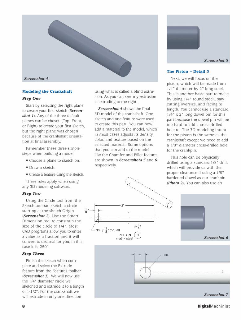
Next, we will focus on the piston, which will be made from 1/4" diameter by 2" long steel. This is another basic part to make by using 1/4" round stock, saw cutting oversize, and facing to length. You cannot use a standard 1/4" x 2" long dowel pin for this part because the dowel pin will be too hard to add a cross-drilled hole to. The 3D modeling intent for the piston is the same as the crankshaft except we need to add a 1/8" diameter cross-drilled hole for the crankpin.
This hole can be physically drilled using a standard 1/8" drill, which will provide us with the proper clearance if using a 1/8" hardened dowel as our crankpin (Photo 2). You can also use an
using what is called a blind extru-sion. As you can see, my extrusion is extruding to the right.
Screenshot 4 shows the final 3D model of the crankshaft. One sketch and one feature were used to create this part. You can now add a material to the model, which in most cases adjusts its density, color, and texture based on the selected material. Some options that you can add to the model, like the Chamfer and Fillet feature, are shown in Screenshots 5 and 6 respectively.
Screenshot 4
Screenshot 5
Screenshot 6
Screenshot 7

Please supportour advertisers
For advertising opportunities in Digital Machinist contact:
Advertising ManagerGretchen Christensen(888) 822-3102 USA
Winter 2012 9
oversize 1/8" reamer for this step. Note that the circle is located 1/8" from the edge and the center is related horizontally with the sketch origin.
Modeling the Piston
Step One
After following the first three steps for modeling the crankshaft, we come to step one for the piston. Remember to extrude the piston to a length of 2" instead of 1-1/2" like the crankshaft. To add the 1/8"
The premier source of tooling, parts,and accessories for bench top machinists.
www.littlemachineshop.com396 W. Washington Blvd. #500 • Pasadena, California 91103 • (800)981-9663
Visit our Web site or call for a free catalog
Back to BasicsIf You're Just Getting Started
…as a hobby machinist, we can help. We have several free guides to tooling and machine operation on our website; click the Learning Center link near the top of every page. You'll nd more useful (and free) information by clicking the nearby Info Center link. For greater depth, we have plenty of books and DVDs for sale.
Did you notice when you brought home your new lathe or mill that it didn't include any of the tooling you needed to actually do anything? We've put together several starter kits that include the essentials—and that save you $8–$16 over buying the items separately.
Books DVDs
Sometimes it's easiest to learn by watching others, and we've got videos from some real experts, including Jose Rodriguez and SwarfRat. Find them at littlemachineshop.com/dvd
Lathe Starter Kit
Items you need to start using your new lathe: high speed steel (HSS) tool bits, tailstock drill chuck, center drills
1261 (5/16" bits) $22.951796 (3/8" bits) $25.95
Mini MillStarter Kit
Clamping kit, 6" thin parallels, 1-2-3 blocks, edge and center nder, T-slot cleaner
1262 $79.95
Micro MillStarter Kit
Items for your Harbor Freight Micro Mill/Drill: Clamping kit, 3" thin parallels, 1-2-3 blocks, edge and center nder
2653 $78.95
MeasurementStarter Kit
6" caliper, 6" steel rule, 1" stroke dial indicator, magnetic base
1259 (dial caliper) $29.951260 (digital) $39.95
We have over two dozen titles, including training guides and reference books. To see them all, visit littlemachineshop.com/books
2
Screenshot 8

10 DigitalMach in i s t
cross-drilled hole to the 3D model we need to first create a sketch on the front plane (Screenshot 7).
Remember the three simple rules when building a model:
•Chooseaplanetosketchon.
•Drawasketch.
•Createafeatureusingthesketch.
Step Two
Select the sketch from your feature tree and Extrude Cut the circle using the Through All selection for both Direction 1 and Direction 2. Since the front plane is cutting through the center of the piston we need to specify this double “Through All” direction in order to accomplish the task (Screenshot 8).
Step Three
Here is the finished piston (Screenshot 9). You can add chamfers and fillets to the ends of the piston if you like. You can also add a lead-in chamfer to the cross-drilled hole.
The Crank Disk – Detail 4
Next, we can build the crank disk, which will be 3/4" diameter by 3/16" thick steel when com-plete. The crank disk can be made
Screenshot 9
Screenshot 10
Screenshot 12Screenshot 11
3

rt-stepper USB-to-Parallel dongleConvert your parallel port
CNC controller to aUSB CNC controller
www.ecklersoft.com
embedded real time control
step resolution 46,875 HzLinux, Mac
and Windows compatible
®P.O. Box 299, Eagle Point, OR 97524 • WWW.MESATOOL.COM
Turning & Profiling
Boring Head Attachment
Boring Bars
Threading & Grooving
Winter 2012 11
from a piece of 3/4" diameter stock faced and turned to a length of approximately 1/4" long, or as long as you need to clean up for your parting tool. Center drill, drill, and use a 1/4" reamer to achieve a close running fit on the crankshaft. Then use the lathe to part off the disk to the 3/16" thickness.
The last two steps are cross drilling for the 6-32 tapped hole for the setscrew and the 1/8" reamed hole for the crankpin as shown in Photo 3.
Modeling the Crank Disk
Step One
The first step in creating the crank disk is a simple sketch of a 3/4" diameter circle drawn on the right plane (Screenshot 10). We then extrude the circle using the Mid Plane option to a thickness of 3/16". Using the Mid Plane option extrudes half the thickness towards
the left and the other half towards the right, splitting the overall thickness in half. By doing this we are keeping the right plane cen-tered in the middle of the part. This technique will allow you to add features to the outside diam-eter of the disk and keep those features centered. We will be adding a tapped hole to this model later on and the Mid Plane tech-nique will become quite useful.
Step Two
Next we add the 1/4" diameter through hole for the crankshaft (Screenshot 11). Select the right surface of the part as your sketch-ing plane and create the circle. Use the Extrude Cut feature to cut the hole using the Through All selec-tion. If a hole or slot is cut through the entire part you should always use the Through All option. This is done so that if the part thickness is changed, the hole or slot will
always cut through the part regardless of its thickness.
Step Three
Use the same method as in step two to add the crankpin hole. Using the same surface to sketch on, create a new sketch of a circle 1/8" in diameter and offset 1/4" (Screenshot 12). It is very impor-tant that the center of the crank disk is related horizontally with the center of the 1/8" hole. The Horizontal sketch relation is used to do this. This relation prevents the 1/8" hole from floating around and keeps it in-line as intended.
Step Four
These next few tasks are a bit tricky and may require some practice. We are now ready to add the 6-32 tapped hole to the outside diameter of the disk for our setscrew. We will be using the feature called Hole Wizard to do this.

12 DigitalMach in i s t
Hole Wizard is going to require a starting location, or center point, of the hole. Screenshot 13 shows what looks like crosshairs. This is actually a front view of the disk displaying the top plane and the right plane of the model. We used the Mid Plane option before because our intent was to have this tapped hole centered. We can now utilize the two default planes in our model to add an axis. Select Reference Geometry and then Axis from the list. Use the intersection of two planes as a selection and choose the two planes from the model tree
or graphics area. SolidWorks will put an axis directly through the intersection of those two planes, which will be used to properly center our tapped hole.
Step Five
Using Hole Wizard, you will notice two tabs at the top of the menu. Under the Type tab, select the type of hole you want to add. In this case, we want to choose a 6-32 tapped hole (Screenshot 14). Once the type of hole is chosen you can click on the Position tab to locate the hole. Select the outside diameter of the disk as your first selection. Use the Point tool from the Sketch toolbar and add a coincident relation between the point and the axis we created.
Screenshot 15 is a cross-section of the disk showing our results. If you cannot see the tapped hole displayed in your drawing as shown here, it may be your display settings. Turn All Annotations on in the View drop-down menu and then go to the Tools drop-down, Options, Document Properties, Detailing, and click the Cosmetic Threads and Shaded Cosmetic Threads checkboxes.
Screenshot 16 shows what the finished crank disk should look like. Notice the crankpin is not shown because we have not modeled it yet! Normally, we would finish the disk, press fit in the crankpin, and be done. In 3D modeling we need to model the
Screenshot 13
Screenshot 15
Screenshot 16
Screenshot 14
4


14 DigitalMach in i s t
pin and then create an assembly within the program to fit the two pieces together. Our finished crank disk will be an assembly of those two parts.
The Flywheel – Detail 5
The flywheel for this engine can be made from aluminum, brass, or steel (Photo 4). The overall size and shape will be 3" diameter by 1/2" thick. I added a recess to each side, as well as some holes to lighten it up towards the center. What I did not include in the modeling example is the tapped hole for a setscrew. I have added my setscrew on a slight angle, drilled and tapped toward the center of the flywheel. I have machined other flywheels with the tapped hole located on their outer faces as well. A 6-32 or 8-32 setscrew can be used.
Modeling the Flywheel
Step One
Start by sketching a 3" diameter circle on the front plane (Screen-shot 17). In the same sketch, we can add the crank bore by drawing a 1/4" diameter circle. If both circles are started from the sketch origin they will be automatically con-strained and require only the diameter dimensions.
Step Two
Use the Mid Plane option to ex- trude the flywheel to a thickness of 1/2" (Screenshot 18).
Step Three
Sketching on the front surface of the flywheel, we can add two more circles to simulate a cutout or face groove. I have chosen a 3/4" circle and a 2-1/4" circle respectively (Screenshot 19).
Step Four
Extrude Cut this finished sketch to a depth of 1/8" (Screenshot 20).
Step Five
This face groove can be dupli-cated on the opposite side of the flywheel by using the Mirror tool from the Feature’s toolbar (Screen-shot 21). Select the front plane as your mirror plane and the Extrude Cut (face groove) as your “Feature to Mirror.”
Another option would be to sketch on the back surface of the flywheel and perform another
Screenshot 17Screenshot 18
Screenshot 19
Screenshot 20

100% MADE IN USA - ORANGEVISE.COM
Winter 2012 15
Extrude Cut the same as the first. Using the Mirror feature creates an association – what you do to one side, SolidWorks will do to the other. It creates a mirror image of your feature or sketch.
Screenshot 22 is the flywheel shown with a full cross-section. It
is now ready for a spoke pattern or standard hole pattern.
Step Six
Screenshot 23 is a sketch containing a 3/8" diameter hole fixed to a 1-1/2" diameter bolt circle. The 1-1/2" diameter hole
was changed to a construction circle because it will not be extruded or cut; it will be used for construction purposes only. I also added a vertical relation between the center of the 3/8" circle and the sketch origin.
Step Seven
An Extrude Cut using the Through All option works best here (Screenshot 24).
Step Eight
Last, I used a Circular Pattern to create the seven remaining holes as shown in Screenshot 25. The outer diameter circular edge was chosen as my circular parameter and the
Screenshot 21
Screenshot 23 Screenshot 24
Screenshot 22

16 DigitalMach in i s t
feature to pattern is, of course, the 3/8" hole. I entered in a value of eight holes total and the program automatically divided 360° by 8 to place each angular increment.
Step Nine
The completed flywheel, with some added color to make it pop, is shown in Screenshot 26. Select any surface, then click the Edit drop-down menu, then Appearances, and change your color if desired.
The Cylinder – Detail 6
The cylinder is a straight milling job consisting of squaring up a 1-3/8" x 3/4" x 1/2" piece of clear acrylic. Any clear plastic will work if you want to see through the engine, or you can use a piece of
brass instead. When machining this part, I have drilled and reamed the piston bore to suit the piston material. Often I have had to use a .001" oversize 1/4" diameter reamer and have had 100% success in running the engine.
I mark the approximate locations of where the pivot hole and air hole need to be. It is very easy to put this hole on the wrong end if you’re not paying attention (I have done this – twice!). A simple layout using a marker will help you avoid making any silly mistakes. The 3/32" air hole must have a crisp, sharp edge to avoid any input air leaking into the output hole or vice versa. The pivot hole can be drilled and tapped through to the cylinder
hole, but this may let air escape, so use some Teflon tape if you plan on drilling through. In Photo 5 I have drilled and tapped a 10-32 UNF hole as far as I could without breaking through to the piston bore.
Modeling the Cylinder
Step One
First, I sketched a 1-3/8" x 1/2" rectangle on the Right plane and extruded this shape to a Mid Plane depth of 3/4" wide (Screenshot 27).
Step Two
Next, I used Hole Wizard to add the 1/4" diameter piston bore simply because Hole Wizard will give you the nice drill point seen at the end of the drilled hole
Screenshot 25 Screenshot 26
Screenshot 27

Winter 2012
(Screenshot 28). A regular extrud-ed cut would work here but it would not give you the drill point. A revolved cut would also work and give you the drill point but would require a work plane to sketch on. Hole Wizard should be used whenever a hole is being modeled; it is good modeling practice to do so.
Steps Three and Four
In Screenshot 29, you can see the finished cylinder with the 3/32" air hole and the 10-32 UNF pivot hole, both done using Hole Wizard.
In the next issue we will com-plete the engine project. We have
one last component to make, the frame, and then can move on to the task of assembling the engine in CAD.
End Mill Holders for ER16, Sherline, TaigSpherical Nut & WasherMill Tooling Plates for Taig,Sherline, Chinese MillsBlank Arbors ER16, Sherline, TaigBoring Head & Drill Chuck ArborsSherline Modular Z RiserSherline Headstock RiserSteel T-Slot StripsSherline, Taig, Chinese T-Slot Cleaners & much more!
OTHER ITEMS
Includes bearings. Fits Lathe & Mill $49.95 each
CNC MOTORMOUNT FORSHERLINE
LIFETIME GUARANTEE
Custom Engineered For: >Sherline, Taig, Chinese, Unimat>Machined from 12L14 Steel>Mill Spec Black Oxide Finished
$7.45-$16.00 SET
TUFF NUT T-NUTS
Hard anodized laser etched AL 6061 $19.95 - $31.95>Available in 6 sizes from 1.7" to 5.5" long<12 pcs Stud pack 10-32 $9.9552 pcs Cap Screw pack10-3x1/2" to 2-1/2" $12.95
MILL CLAMPS
Fits most hobby sized lathes, including:>Taig, Sherline, Chinese 7x, 8x, 9x, Atlas 6", Sieg>Includes mounting kit & 4 tool holders>Machined from AL 6061 and Hard Anodized
$99.95
QUICK CHANGETOOL POST
Includes Kerk precision screws, extended XYZ,BB Thrust Collars, Sherline Spindle & Motor,Zero Adjust Hand Wheels, 2.2" Headstock Spacer
14"X, 11"Y, 16" Z TravelVisit our Webstore for details
Complete Manual Mill Now AvailableEasily Upgraded to CNC
Precision XY Leadscrew Set
Extended travel upgrades can be installedsingly or all at once to make a Monster Mill
Z-COLUMN: 16” TravelBolt-on installation for 5xxx or 2xxx millsIncludes Kerk precision leadscrew
$845.00
X-TABLE: 14" TravelY-BASE: 11" TravelExtended std screw included
Table: $220.00Base: $255.00
Includes Kerk Precision screws andanti-lash nut & custom saddle.Version for stock or extended millsUse our BB Thrust Collar for manual mills
$415.00-$435.00
Individual Upgrades for your Sherline MONSTER MILL
MADE
IN THE
U.S.A.
3955 S. Mariposa St • Englewood CO 80110720-833-9300 • 877-754-7465
A2Z CORP
A2Z CORP3955 S. Mariposa St • Englewood, CO 80110
720-833-9300 • 877-754-7465 Visit our online store to purchase more products
www.A2ZCorp.us/store
5
Screenshot 28
Screenshot 29