3d geomechanics model smeaheia choi et al - sintef.no
20
Geomechanical Risk Assessment Using Field Scale Geomechanics 3D Model: Case Study on Smeaheia CO2 Storage Site 18.June.2019 Jung Chan CHOI, Huynh Dat Vu Khoa, Elin Skurtveit, Lars Grande, Joonsang Park
Transcript of 3d geomechanics model smeaheia choi et al - sintef.no

Geomechanical Risk Assessment Using Field
Scale Geomechanics 3D Model: Case Study on
Smeaheia CO2 Storage Site
18.June.2019
Jung Chan CHOI, Huynh Dat Vu Khoa, Elin Skurtveit, Lars Grande, Joonsang Park

Smeaheia CO2 storage site
(Equinor, 2016)
Located at Horda Platform East of Troll field
High porous saline aquifer reservoir at the depth of 1200-1500 m below sea level
Two large storage structures Alpha and Beta, which has CO2 storage capacity of 100 Mt each

Geomechanics risk on Smeaheia
Reactivation of Vette and Øygarden faults
Caprock integrity
Seabed heave and Associated geohazard
2.5 km
Alpha
W E
Thinner caprock
Beta
PM
P-faults
Basement Juxtaposition
Juxtaposition
Key risks
Intense faulting
Shallow level
VE: 5
Mulrooney et al., 2018

Previous study on derisking CO2 storage sites
Skurtveit et al., 2018 Choi et al., 2015
Fault stability for Smeaheia area 2D geomechanics model for Snøhvit

Objective and scope of work
Aims to develop full 3D FE model for geomechanical stability analyses of reservoir at Smeaheia site
improving understanding on the stress change and associated instability in caprock and faults in Smeaheia site

Modeling procedure NGI’s in-house workflow that can build 3D geomechanics model by linking Eclipse, Geomodel and Abaqus is used
Model geometry and mesh
Material properties assignment
Initial condition assignment
Validation against data from wells
Geomechanical simulation
Boundary condition assignment
Load history
Geological model
Reservoir model
Fault geometry
Saturation, Pressure
In-situ stress
Lab-testing data
Core, logs and direct
measures
Geomechanical
properties
Analysis
NGI in-house workflow ResGeomechModeler

Layer No. Top of layer Depth_mean thickness
1 00_Seabed.txt -301.5 513.8
2 01_Top Shetland Gp.txt -815.3 255.86
3 02_Draupne Fm.txt -1071.16 204.24
4 03_Sognefjord Fm.txt -1275.4 162.1
5 04_Fensfjord Fm.txt -1437.5 125.7
6 05_Brent Gp.txt -1563.2 13.5
7 06_Dunlin Gp.txt -1576.7 22.1
8 07_Johansen Fm.txt -1598.8 25.5
9 08_Top Statfjord Fm.txt -1624.3 1375.7
Bottom of the model -3000
Geometry
Reservoir
9 Fm. or Gp. are included Number elements = 1.5 mil Element type: C3D8RP (8-node trilinear displacement and pore pressure, reduced integration)
-3km

Stress condition
Data from Northern Lights data package
• K0 = 0.45 • Gamma_v_eff = 10.235 kPa/m from seabed • Hydrostatic_pp_gradient = 9.905 – 10.069kPa/m

Material input Data package from Northern Lights project and interal NGI database are used.
Porosity dependent material properties are used for the reservoir
Porosity [-]
Young’s modulus [kPa]
Injection well SDL#1

Reservoir pressure
Reservoir simultion from Equinor 2016 feasibility study (Statoil, 2016) are used as a basis.
Injection of 1.3 MT CO2/yr during 25yrs (total injection of 32.MT CO2) is considered for the model.
The injection well is considered as SDL#2, which is in Alpha structure.
At 2045, the pressure build up near injector is around 11 bar

Pressure build-up in the reservoir
Yr 2045
Yr 2145
Injection well SDL#2
Unit: kPa
Unit: kPa

Vertical deformation in reservoir
Yr 2045 Yr 2145
Unit: m
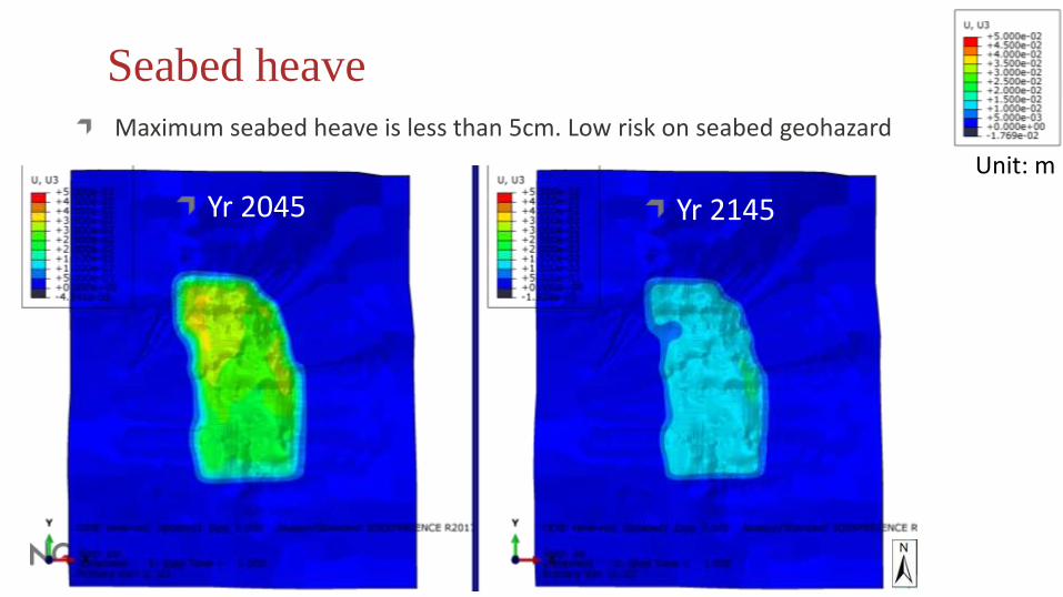
Seabed heave
Yr 2045 Yr 2145
Maximum seabed heave is less than 5cm. Low risk on seabed geohazard
Unit: m

Injection-induced porosity change in the reservoir
Porosity change is less than 0.1% during the injection
Yr 2045
Yr 2145
Unit: -
Unit: -

Stress path in reservoir
Failure during the planned injection is unlikely
Unit: kPa
Vertical effective stress Yr2045

Stress change and integrity in the caprock Maximum stress change in the caprock is about 200 kPa (<20% max change in reservoir). Mechanical failure of caprock is unlikely for the selected injection scenario
Unit: kPa
Change in vertical effective stress Yr2045

Stability of Vette fault In the given scenario, reactivation of Vette fault is unlikely. The analytical approach used in Skurtveit et al., (2018) seems to be conservative

Summary
This study presents how to evaluate the geomechanical risk of CO2 storage using a field scale 3D geomechanics model.
For Smeaheia area, when the injection of 1.3 MT CO2/yr during 25yrs at the SDL#2 is considered, the evaluated geomechanical risks are as follows:
─ Seabed heave and associated geohazard: Low
─ Injection-induced caprock integrity: Low
─ Injection-induced porosity change in reservoir: <1%
─ Reactivation of Vette fault: Low
3D geomechanics model is ready to investigate effects of various scenario easily. Further works incorporated with other research projects (SPHINCCS, OASIS, NCCS, IGCCS) are ongoing to investigate various scenarios (e.g. different injection scenario, effect of depletion in Troll, microseismicity, etc..)

Thank you for your attention!
19
This publication has been produced with support from the NCCS Centre, performed under the Norwegian research program
Centres for Environment-friendly Energy Research (FME). The authors acknowledge the following partners for their
contributions: Aker Solutions, Ansaldo Energia, CoorsTek Membrane Sciences, Emgs, Equinor, Gassco, Krohne, Larvik
Shipping, Norcem, Norwegian Oil and Gas, Quad Geometrics, Shell, Total, Vår Energi, and the Research Council of Norway.
Work was conducted in close collaboration with the Northern Lights project (Equinor, Total, Shell).

NORWEGIAN GEOTECHNICAL INSTITUTE NGI.NO
#onsafeground