3D friction map Friction in Elasto Hydrodynamically .../file/MarcusBjorling.pdf · Friction in...
43
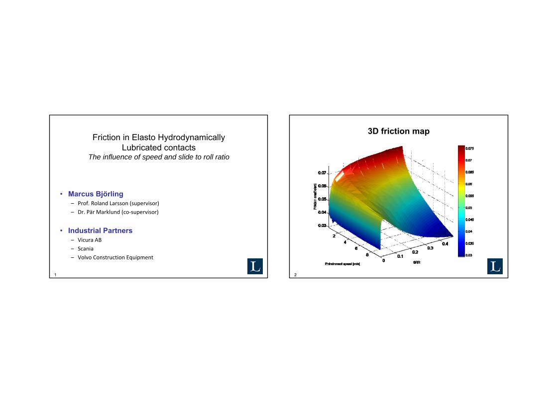
1 Friction in Elasto Hydrodynamically Lubricated contacts The influence of speed and slide to roll ratio • Marcus Björling – Prof. Roland Larsson (supervisor) – Dr. Pär Marklund (co-supervisor) • Industrial Partners – Vicura AB – Scania – Volvo Construction Equipment 2 3D friction map
Transcript of 3D friction map Friction in Elasto Hydrodynamically .../file/MarcusBjorling.pdf · Friction in...
1
Friction in Elasto HydrodynamicallyLubricated contacts
The influence of speed and slide to roll ratio
• Marcus Björling– Prof. Roland Larsson (supervisor)
– Dr. Pär Marklund (co-supervisor)
• Industrial Partners– Vicura AB
– Scania
– Volvo Construction Equipment
2
3D friction map
3
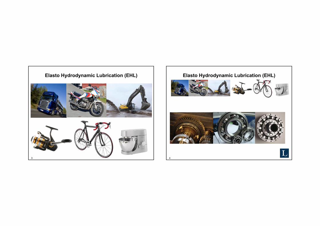
Elasto Hydrodynamic Lubrication (EHL)
4
Elasto Hydrodynamic Lubrication (EHL)

5
Project aims
• Improve the understanding of friction in EHL
• Find a good way to map out system performance
• Improve efficiency of machine components working in EHL
6
Conformal and non conformal contacts
Lubricant
Small contact areaHigh contact pressure
Large contact areaLow contact pressure
7
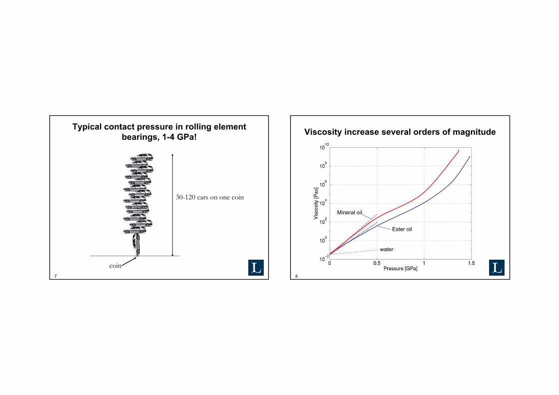
Typical contact pressure in rolling element bearings, 1-4 GPa!
30-120 cars on one coin
coin8
Viscosity increase several orders of magnitude
water
Mineral oil
Ester oil

9
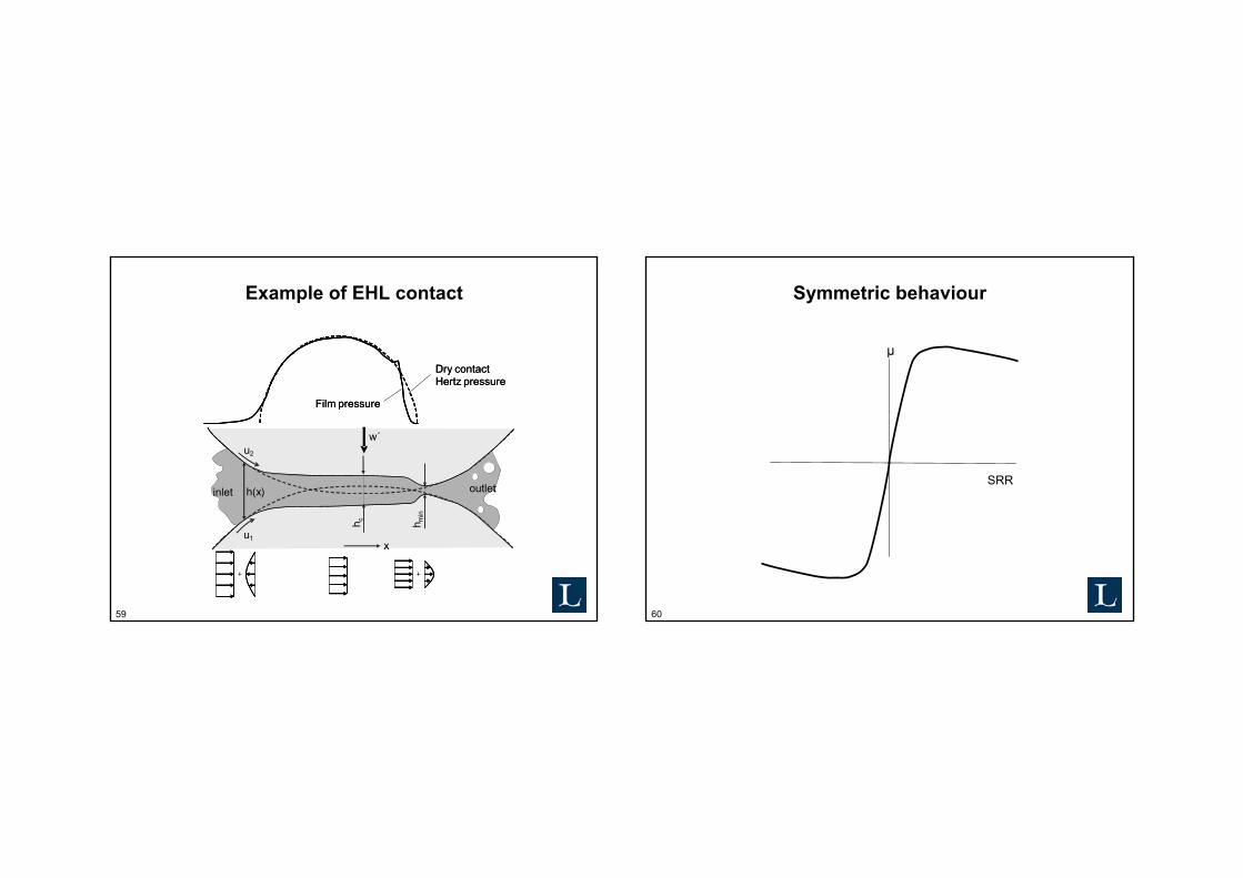
Example of EHL contact
u1
u2
w
inlet outlet
10
Example of EHL contact
inlet outlet
u1
u2
h(x)
w´
h min
h c
inlet outlet
u1
u2
w
Film pressure
Dry contactHertz pressure
Film pressure
Dry contactHertz pressure
h c
ViscosityEntrainment speedPressure-viscosity behaviour…
Not to scale!

11
EHL shear profile
u2
u1
u1=u2 No sliding
12
EHL shear profile
u2
u1
u1<u2 sliding

13
Limiting shear stress
Shear stress
Shear strain rate
Linear
Non-Linear Limiting shear stress
Thermal
14
Friction versus Slide to Roll Ratio (μ-slip)
μ
SRR
15
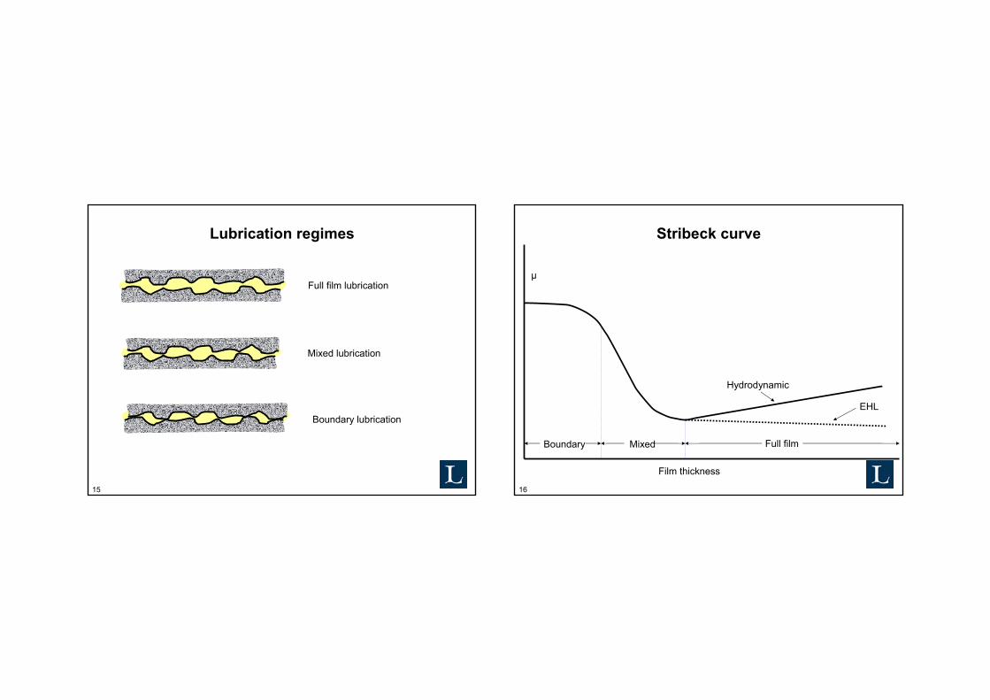
Lubrication regimes
Full film lubrication
Mixed lubrication
Boundary lubrication
16
Stribeck curve
Boundary Mixed Full film
Film thickness
μ
EHL
Hydrodynamic
17
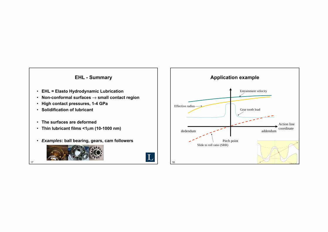
EHL - Summary
• EHL = Elasto Hydrodynamic Lubrication • Non-conformal surfaces → small contact region• High contact pressures, 1-4 GPa • Solidification of lubricant
• The surfaces are deformed• Thin lubricant films <1μm (10-1000 nm)
• Examples: ball bearing, gears, cam followers
18
Application example
Action line coordinate
dedendum addendum
Pitch point
Entrainment velocity
Slide to roll ratio (SRR)
Effective radiusGear tooth load

19
Wedeven Associates Machine (WAM) no. 11
20
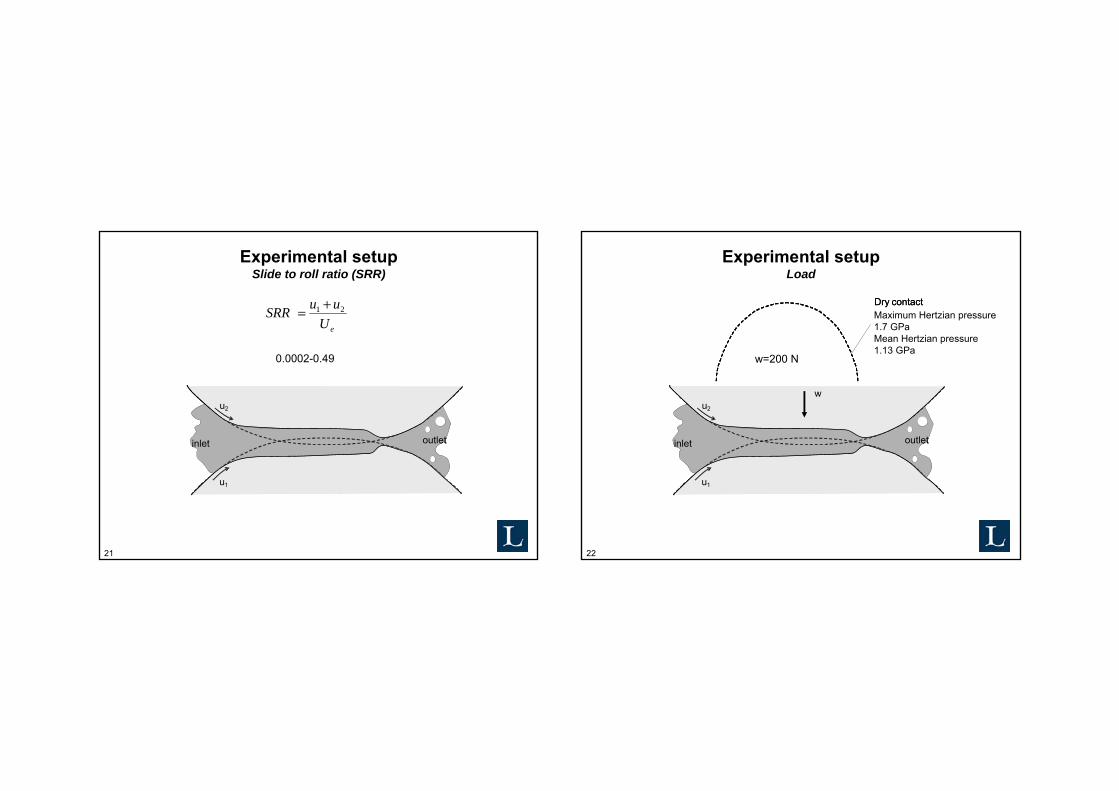
Experimental setupEntrainment speed
inlet outlet
u1
u2
h(x)
w´
h min
h c
inlet outlet
u1
u2
221 uuUe
+=
0.34-9.6 m/s
21
Experimental setupSlide to roll ratio (SRR)
inlet outlet
u1
u2
h(x)
w´
h min
h c
inlet outlet
u1
u2
eUuuSRR 21 +=
0.0002-0.49
22
Experimental setupLoad
inlet outlet
u1
u2
h(x)
w´
h min
h c
Dry contact
inlet outlet
u1
u2
w
Dry contactMaximum Hertzian pressure 1.7 GPaMean Hertzian pressure1.13 GPa
w=200 N

23
3D friction map
24
µ-slip curve
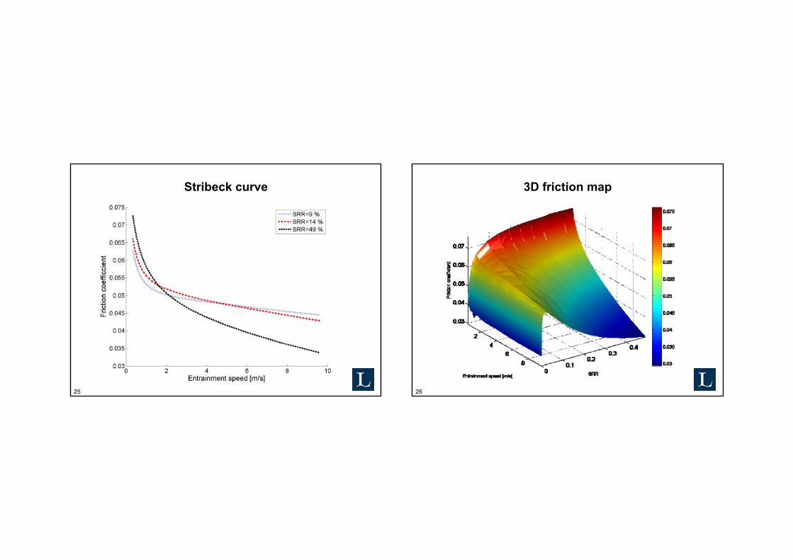
25
Stribeck curve
26
3D friction map

27
2D contour map
28
Schematic 2D map of EHL friction regimes
M T
NL
LEntrainment speed
SRR

29
3D map – EHL friction regimes
Thermal
Mixed
Linear Non-Linear
30
Test parameters
• Temperatures – 40 and 90°C
• Viscosities – low and high
• Base oil type – mineral and ester
• EP additive content – 0 and 2 %
• Surface roughness – rough and smooth
• Coating – uncoated and DLC coated
31
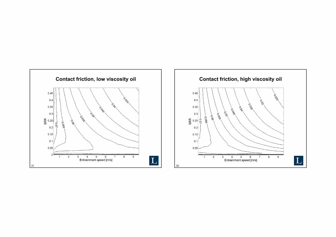
Contact friction, low viscosity oil
32
Contact friction, high viscosity oil
33
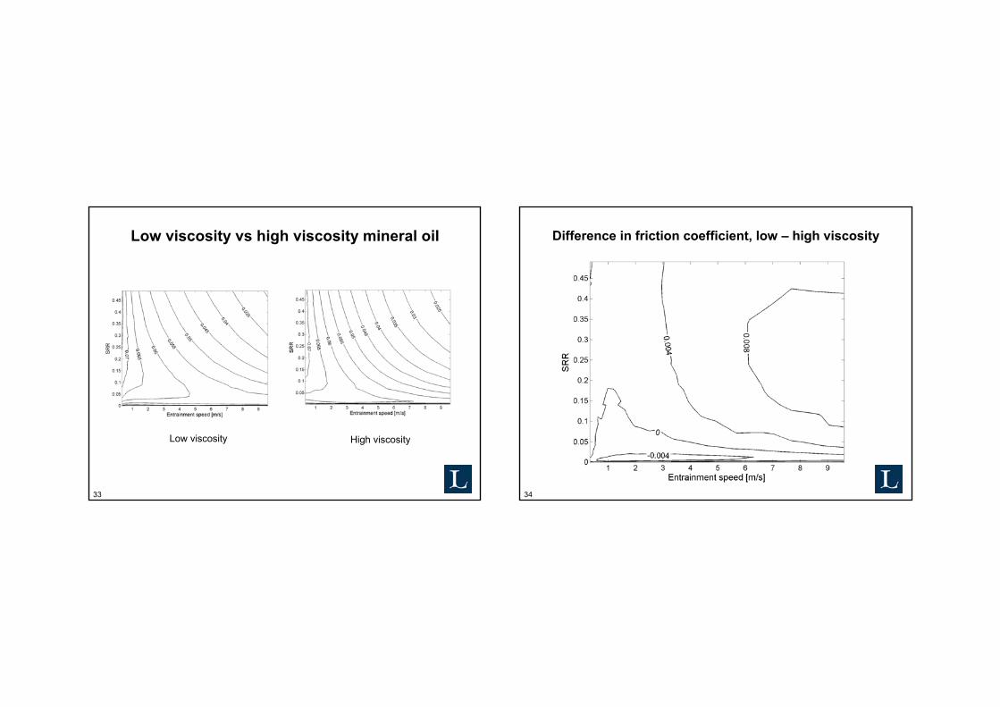
Low viscosity vs high viscosity mineral oil
High viscosityLow viscosity
34
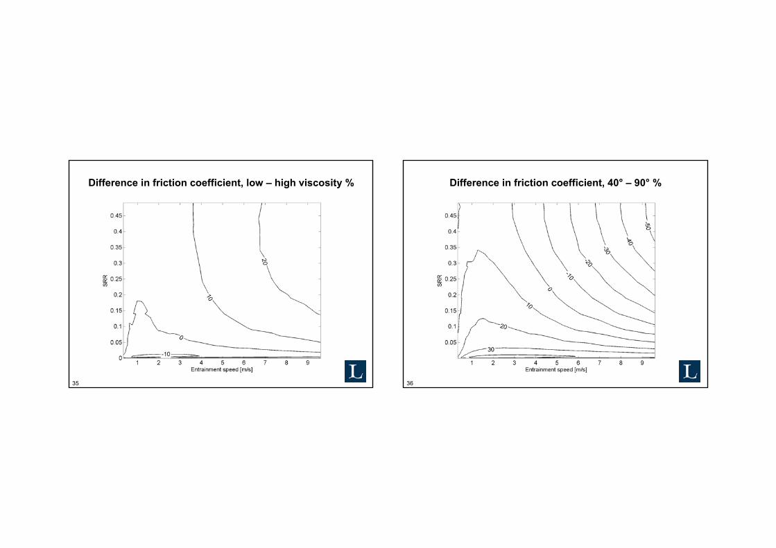
Difference in friction coefficient, low – high viscosity
35
Difference in friction coefficient, low – high viscosity %
36
Difference in friction coefficient, 40° – 90° %

37
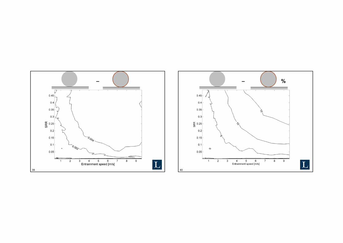
Difference in friction coefficient, mineral – ester %
38
Difference in friction coefficient, rough – smooth %
39
–
40
– %

41
– %
42
1D Simulation modelPrinciple
Lubricant

43
1D Simulation modelSchematics
SteelCoating/Steel
Lubricant
Steel
44
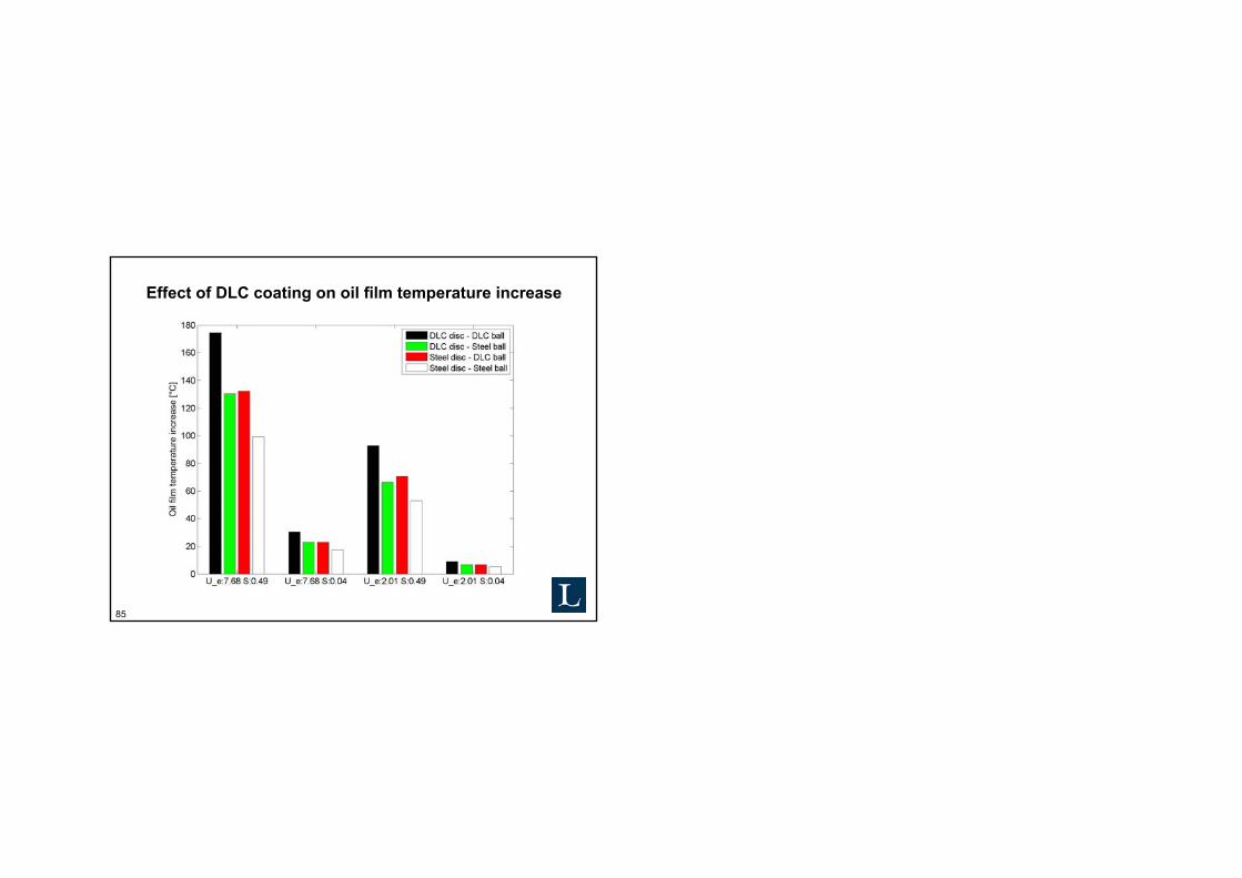
Effect of DLC coating on oil film temperature increase
45
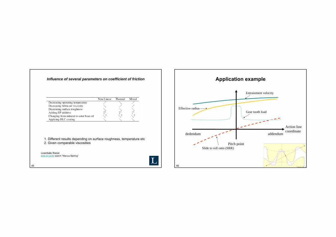
Influence of several parameters on coefficient of friction
1. Different results depending on surface roughness, temperature etc2. Given comparable viscosities
www.ltu.se/lib search ”Marcus Björling”Licentiate thesis:
46
Application example
Action line coordinate
dedendum addendum
Pitch point
Entrainment velocity
Slide to roll ratio (SRR)
Effective radiusGear tooth load

47
Where to operate?
48
Friction power MW/m²
49
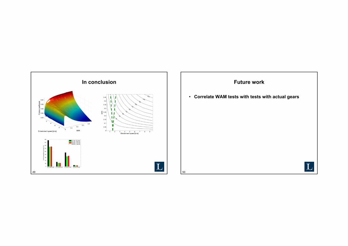
In conclusion
50
Future work
• Correlate WAM tests with tests with actual gears
51
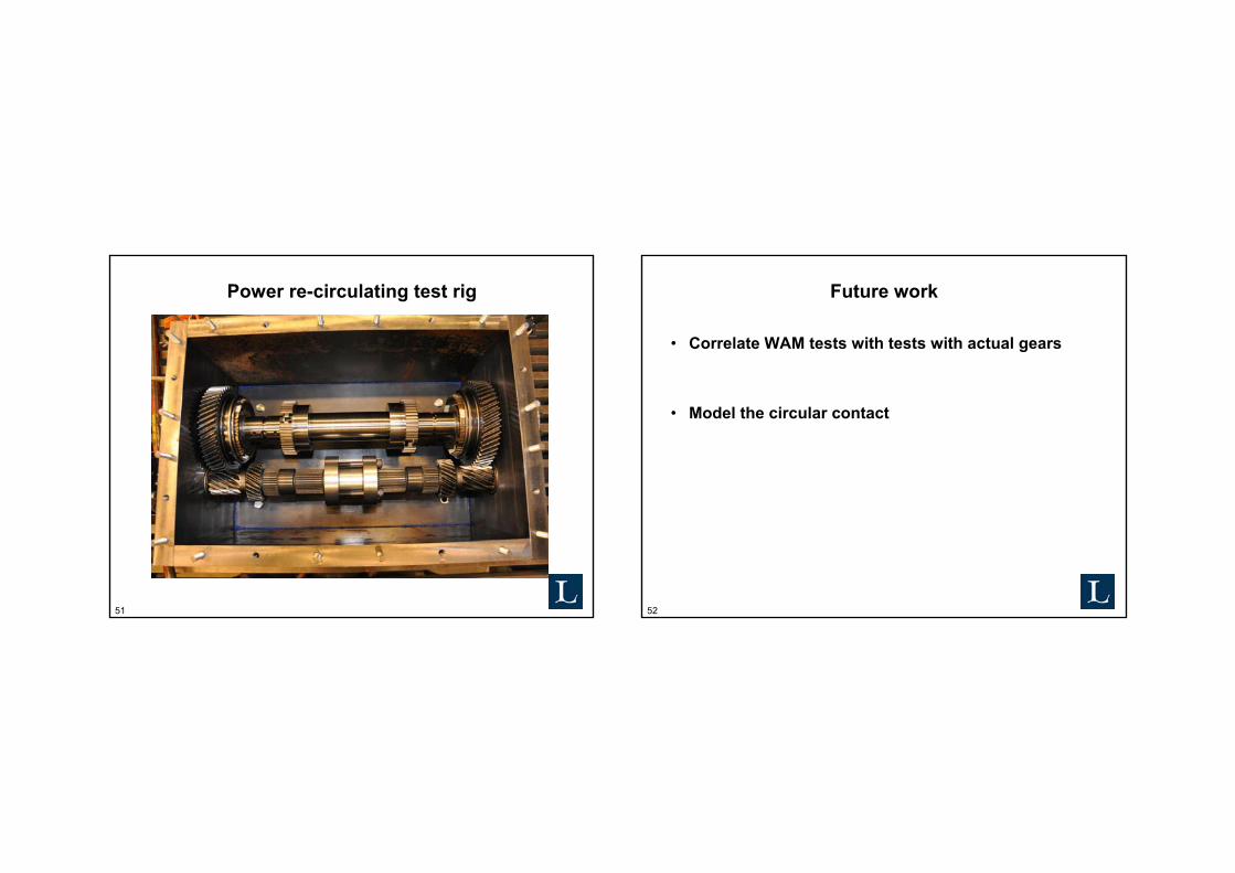
Power re-circulating test rig
52
Future work
• Correlate WAM tests with tests with actual gears
• Model the circular contact
53
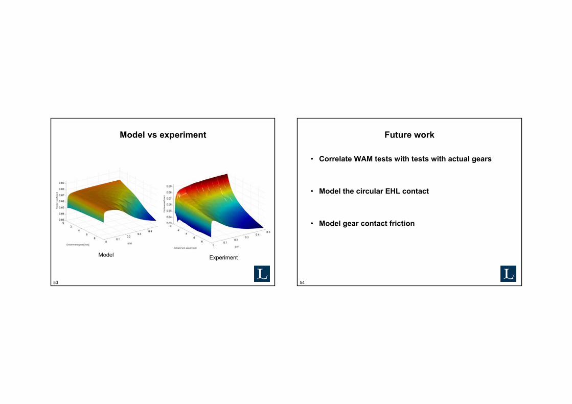
Model vs experiment
ExperimentModel
54
Future work
• Correlate WAM tests with tests with actual gears
• Model the circular EHL contact
• Model gear contact friction
55
Thank you for your attention!
• Volvo Construction Equipment• Scania• Vicura AB
• Statoil Lubricants• IonBond
• Swedish Foundation for Strategic Research (SFF, ProViking)
Questions?
Acknowledgements:
56
Thank you for your attention!
Questions?

57
Test procedure
58
Test procedure
59
Example of EHL contact
inlet outlet
u1
u2
h(x)
w´
h min
h c
Film pressure
Dry contactHertz pressure
+ +
x
inlet outlet
u1
u2
h(x)
w´
h min
h c
Film pressure
Dry contactHertz pressure
+ +
x
60
Symmetric behaviour
μ
SRR
61
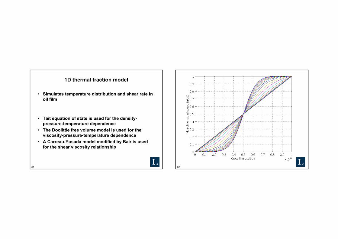
1D thermal traction model
• Simulates temperature distribution and shear rate in oil film
• Tait equation of state is used for the density-pressure-temperature dependence
• The Doolittle free volume model is used for the viscosity-pressure-temperature dependence
• A Carreau-Yusada model modified by Bair is used for the shear viscosity relationship
62
63 64
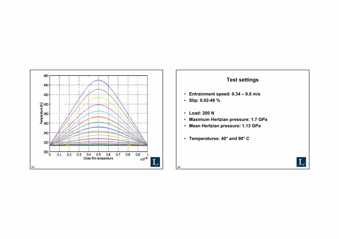
Test settings
• Entrainment speed: 0.34 – 9.6 m/s• Slip: 0.02-49 %
• Load: 200 N• Maximum Hertzian pressure: 1.7 GPa• Mean Hertzian pressure: 1.13 GPa
• Temperatures: 40° and 90° C
65
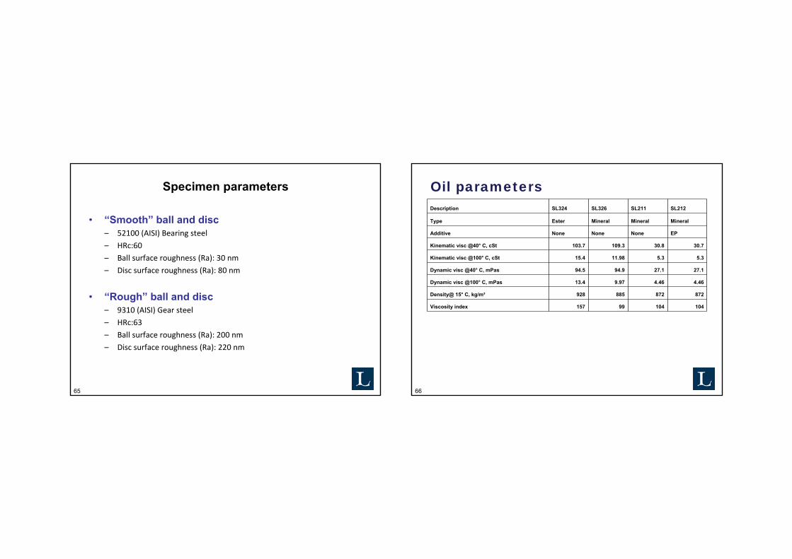
Specimen parameters
• “Smooth” ball and disc– 52100 (AISI) Bearing steel
– HRc:60
– Ball surface roughness (Ra): 30 nm
– Disc surface roughness (Ra): 80 nm
• “Rough” ball and disc– 9310 (AISI) Gear steel
– HRc:63
– Ball surface roughness (Ra): 200 nm
– Disc surface roughness (Ra): 220 nm
66
Oil parametersDescription SL324 SL326 SL211 SL212
Type Ester Mineral Mineral Mineral
Additive None None None EP
Kinematic visc @40° C, cSt 103.7 109.3 30.8 30.7
Kinematic visc @100° C, cSt 15.4 11.98 5.3 5.3
Dynamic visc @40° C, mPas 94.5 94.9 27.1 27.1
Dynamic visc @100° C, mPas 13.4 9.97 4.46 4.46
Density@ 15° C, kg/m³ 928 885 872 872
Viscosity index 157 99 104 104

67
Diamond Like Carbon (DLC) in EHL
In literature• Focus on wear and boundary friction• Mostly pure sliding contacts
New study• Focus on EHL friction in full film lubrication• Rolling and sliding contacts
68
Wedeven Associates Machine (WAM) no. 11
69
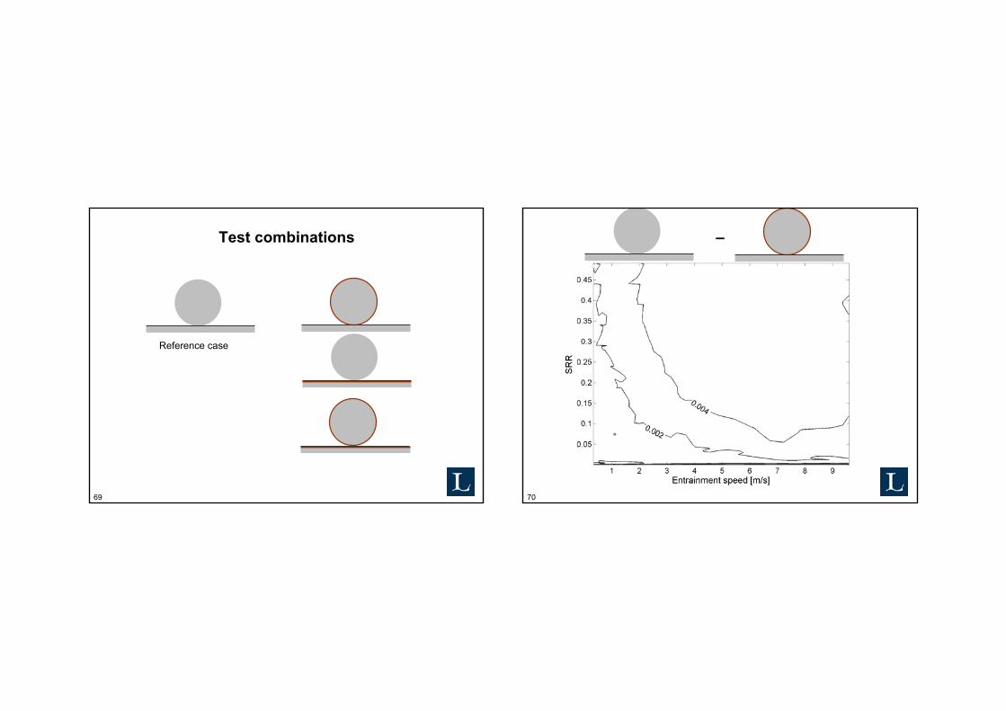
Test combinations
Reference case
70
–
71
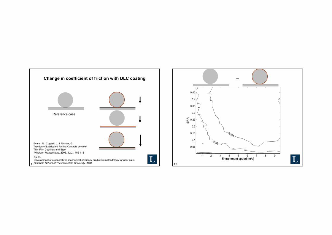
Change in coefficient of friction with DLC coating
Reference case
Xu, H.Development of a generalized mechanical efficiency prediction methodology for gear pairsGraduate School of The Ohio State University, 2005
Evans, R.; Cogdell, J. & Richter, G.Traction of Lubricated Rolling Contacts betweenThin-Film Coatings and SteelTribology Transactions, 2009, 52(1), 106-113
72
–
73
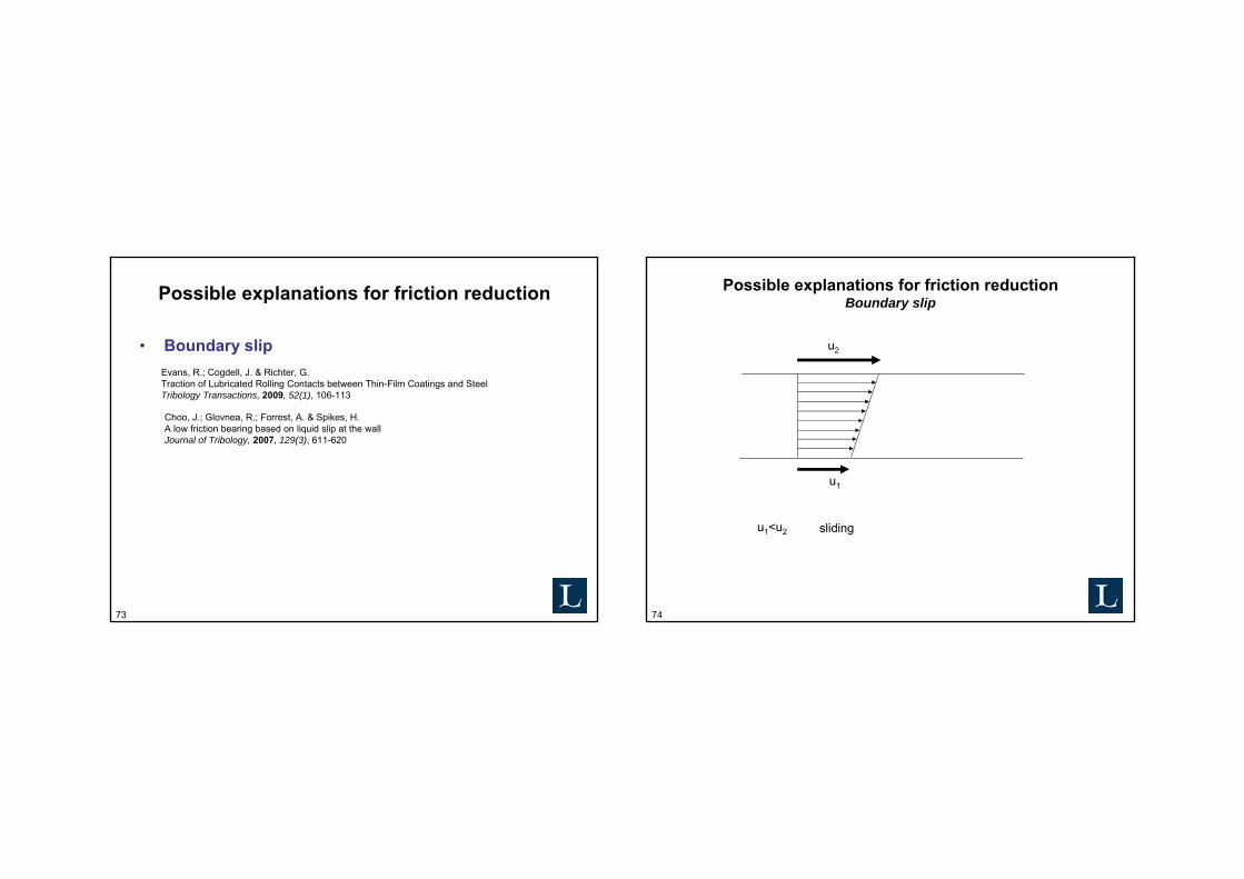
Possible explanations for friction reduction
• Boundary slipEvans, R.; Cogdell, J. & Richter, G.Traction of Lubricated Rolling Contacts between Thin-Film Coatings and SteelTribology Transactions, 2009, 52(1), 106-113
Choo, J.; Glovnea, R.; Forrest, A. & Spikes, H.A low friction bearing based on liquid slip at the wallJournal of Tribology, 2007, 129(3), 611-620
74
Possible explanations for friction reduction Boundary slip
u2
u1
u1<u2 sliding
75
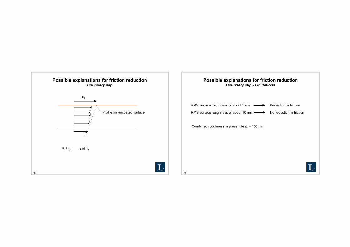
Possible explanations for friction reduction Boundary slip
u2
u1
u1<u2 sliding
Profile for uncoated surface
76
Possible explanations for friction reduction Boundary slip - Limitations
RMS surface roughness of about 1 nm Reduction in friction
RMS surface roughness of about 10 nm No reduction in friction
Combined roughness in present test: > 155 nm
77
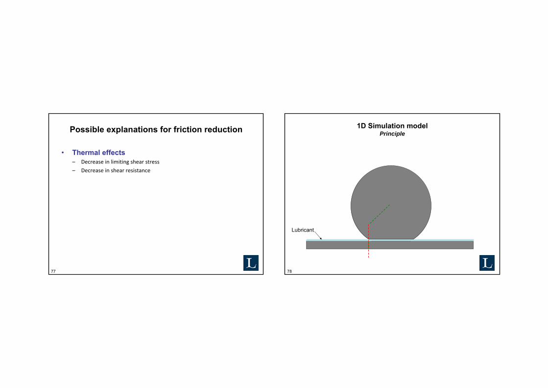
Possible explanations for friction reduction
• Thermal effects– Decrease in limiting shear stress
– Decrease in shear resistance
78
1D Simulation modelPrinciple
Lubricant

79
1D Simulation modelSchematics
SteelCoating/Steel
Lubricant
Steel
80
1D Simulation modelMaterial parameters
SteelCoating/Steel
Steel
DLC 52100(AISI)Density [kg/m³] 2500 7810Thermal conductivity [W/mK] 2 46.6Heat Capacity [J/kgK] 1000 475
Kim, J.; Yang, H.-S.; Jun, Y. & Kim, K.Interfacial effect on thermal conductivity of diamond-like carbon filmsJournal of Mechanical Science and Technology, 2010, 24(7), 1511-1514
Wojciechowski, K.; Zybala, R. & Mania, R.Application of DLC layers in 3-omega thermal conductivity methodJournal of Achievements in Materials and Manufacturing Engineering, 2009, 37(2), 512-517

81
1D Simulation modelFilm thickness
SteelCoating/Steel
Steel
• Hamrock & Dowson central film thickness• Hsu and Lee thermal correction
Hsu, C.-H. & Lee, R.-T.An Efficient Algorithm for Thermal Elastohydrodynamic Lubrication Under Rolling/Sliding Line ContactsJournal of tribology, 1994, 116(4), 762-769
Hamrock, B.Fundamentals of fluid film lubricationMcGraw-Hill, 1994
82
1D Simulation modelBoundary conditions
Bulk temperature Bulk temperature
Heat source
Continuity

83
1D Simulation modelHeat source
Heat source, Q
tPT
hSUPQ h
cen
eh ∂
∂+= εμ
Measured friction coefficientCircular Hertzian pressureSRR and entrainment speedHamrock & Dowson Hsu & LeeCompression of lubricant
84
Data points for simulations
85
Effect of DLC coating on oil film temperature increase