3D Computer Vision and Video Computing 3D Vision Lecture 15 Stereo Vision (II) CSC 59866CD Fall 2004...
38
3D Computer Vision and Video Computing 3D Vision Lecture 15 Stereo Vision (II) CSC 59866CD Fall 2004 Zhigang Zhu, NAC 8/203A http://www-cs.engr.ccny.cuny.edu/~zhu/ Capstone2004/Capstone_Sequence2004.html
-
date post
21-Dec-2015 -
Category
Documents
-
view
217 -
download
0
Transcript of 3D Computer Vision and Video Computing 3D Vision Lecture 15 Stereo Vision (II) CSC 59866CD Fall 2004...
3D Computer Vision
and Video Computing 3D Vision3D Vision
Lecture 15 Stereo Vision (II)
CSC 59866CDFall 2004
Zhigang Zhu, NAC 8/203Ahttp://www-cs.engr.ccny.cuny.edu/~zhu/
Capstone2004/Capstone_Sequence2004.html

3D Computer Vision
and Video Computing Stereo VisionStereo Vision
Epipolar Geometry Where to search correspondences Epipolar plane, epipolar lines and epipoles Essential matrix and fundamental matrix
Correspondence Problem Correlation-based approach Feature-based approach
3D Reconstruction Problem Both intrinsic and extrinsic parameters are known Only intrinsic parameters No prior knowledge of the cameras
3D Computer Vision
and Video Computing Epipolar GeometryEpipolar Geometry
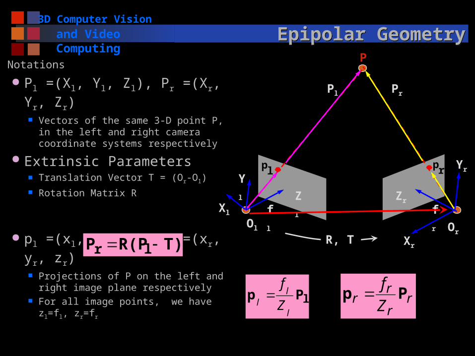
Notations
Pl =(Xl, Yl, Zl), Pr =(Xr, Yr, Zr) Vectors of the same 3-D point P, in
the left and right camera coordinate systems respectively
Extrinsic Parameters Translation Vector T = (Or-Ol) Rotation Matrix R
pl =(xl, yl, zl), pr =(xr, yr, zr) Projections of P on the left and right
image plane respectively For all image points, we have zl=fl,
zr=fr
T)R(PP lr
lPpl
ll Z
f r
r
rr Z
fPp
plpr
P
Ol Or
Xl
Xr
Pl Pr
fl fr
Zl
Yl
Zr
Yr
R, T

3D Computer Vision
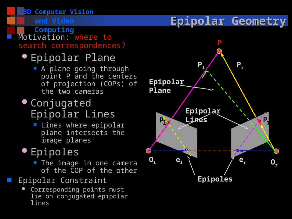
and Video Computing Epipolar GeometryEpipolar Geometry Motivation: where to search
correspondences? Epipolar Plane
A plane going through point P and the centers of projection (COPs) of the two cameras
Conjugated Epipolar Lines
Lines where epipolar plane intersects the image planes
Epipoles The image in one camera of
the COP of the other Epipolar Constraint
Corresponding points must lie on conjugated epipolar lines
pl
pr
P
Ol Orel er
Pl Pr
Epipolar Plane
Epipolar Lines
Epipoles
3D Computer Vision
and Video Computing Epipolar GeometryEpipolar Geometry Motivation: where to search
correspondences? Epipolar Plane
A plane going through point P and the centers of projection (COPs) of the two cameras
Conjugated Epipolar Lines
Lines where epipolar plane intersects the image planes
Epipoles The image in one camera of
the COP of the other Epipolar Constraint
Corresponding points must lie on conjugated epipolar lines
pl
pr
P
Ol Orel er
Pl Pr
Epipolar Plane
Epipolar Lines
Epipoles

3D Computer Vision
and Video Computing Essential MatrixEssential Matrix
Equation of the epipolar plane Co-planarity condition of vectors Pl, T and Pl-T
Essential Matrix E = RS 3x3 matrix constructed from R and T (extrinsic only)
Rank (E) = 2, two equal nonzero singular values
0 ll PTT)(P T
0
0
0
xy
xz
yz
TT
TT
TT
S
333231
232221
131211
rrr
rrr
rrr
R
Rank (R) =3 Rank (S) =2
T)R(PP lr
0lTr EPP
0lTr Epp
lPpl
ll Z
f r
r
rr Z
fPp

3D Computer Vision
and Video Computing Essential MatrixEssential Matrix
Essential Matrix E = RS A natural link between the stereo point pair and the
extrinsic parameters of the stereo system One correspondence -> a linear equation of 9 entries Given 8 pairs of (pl, pr) -> E
Mapping between points and epipolar lines we are looking for
Given pl, E -> pr on the projective line in the right plane Equation represents the epipolar line of either pr (or pl) in
the right (or left) image
Note: pl, pr are in the camera coordinate system, not pixel
coordinates that we can measure
0lTr Epp

3D Computer Vision
and Video Computing Fundamental MatrixFundamental Matrix
Mapping between points and epipolar lines in the pixel coordinate systems With no prior knowledge on the stereo system
From Camera to Pixels: Matrices of intrinsic parameters
Questions: What are fx, fy, ox, oy ? How to measure pl in images?
0lTr pFp
1 lr EMMF T
l1ll pMp rrr pMp 1
100
0
0
int yy
xx
of
of
M0l
Tr Epp
Rank (Mint) =3

3D Computer Vision
and Video Computing Fundamental MatrixFundamental Matrix
Fundamental Matrix Rank (F) = 2 Encodes info on both intrinsic and extrinsic parameters
Enables full reconstruction of the epipolar geometry In pixel coordinate systems without any knowledge of
the intrinsic and extrinsic parameters Linear equation of the 9 entries of F
0lTr pFp
1 lr EMMF T
0
1333231
232221
131211
)1( )(
)(
)()(
rim
rim
lim
lim y
x
fff
fff
fff
yx

3D Computer Vision
and Video ComputingComputing F: The Eight-point AlgorithmComputing F: The Eight-point Algorithm Input: n point correspondences ( n >= 8)
Construct homogeneous system Ax= 0 from x = (f11,f12, ,f13, f21,f22,f23 f31,f32, f33) : entries in F Each correspondence give one equation A is a nx9 matrix
Obtain estimate F^ by SVD of A x (up to a scale) is column of V corresponding to the least
singular value Enforce singularity constraint: since Rank (F) = 2
Compute SVD of F^ Set the smallest singular value to 0: D -> D’ Correct estimate of F :
Output: the estimate of the fundamental matrix, F’ Similarly we can compute E given intrinsic parameters
0lTr pFp
TUDVA
TUDVF ˆ
TVUDF' '

3D Computer Vision
and Video ComputingLocating the Epipoles from FLocating the Epipoles from F
Input: Fundamental Matrix F Find the SVD of F The epipole el is the column of V corresponding to the
null singular value (as shown above) The epipole er is the column of U corresponding to the
null singular value (similar treatment as for e l) Output: Epipole el and er
TUDVF
el lies on all the epipolar lines of the left image
0lTr pFp
0lTr eFp
F is not identically zero
For every pr
0leF
pl pr
P
Ol Orel er
Pl Pr
Epipolar Plane
Epipolar Lines
Epipoles
3D Computer Vision
and Video Computing Stereo RectificationStereo Rectification
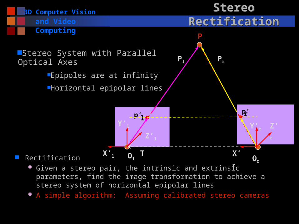
Rectification Given a stereo pair, the intrinsic and extrinsic parameters, find
the image transformation to achieve a stereo system of horizontal epipolar lines
A simple algorithm: Assuming calibrated stereo cameras
p’lp’r
P
Ol Or
X’r
Pl Pr
Z’l
Y’l Y’r
TX’l
Z’r
Stereo System with Parallel Optical AxesEpipoles are at infinity
Horizontal epipolar lines
3D Computer Vision
and Video Computing Stereo RectificationStereo Rectification
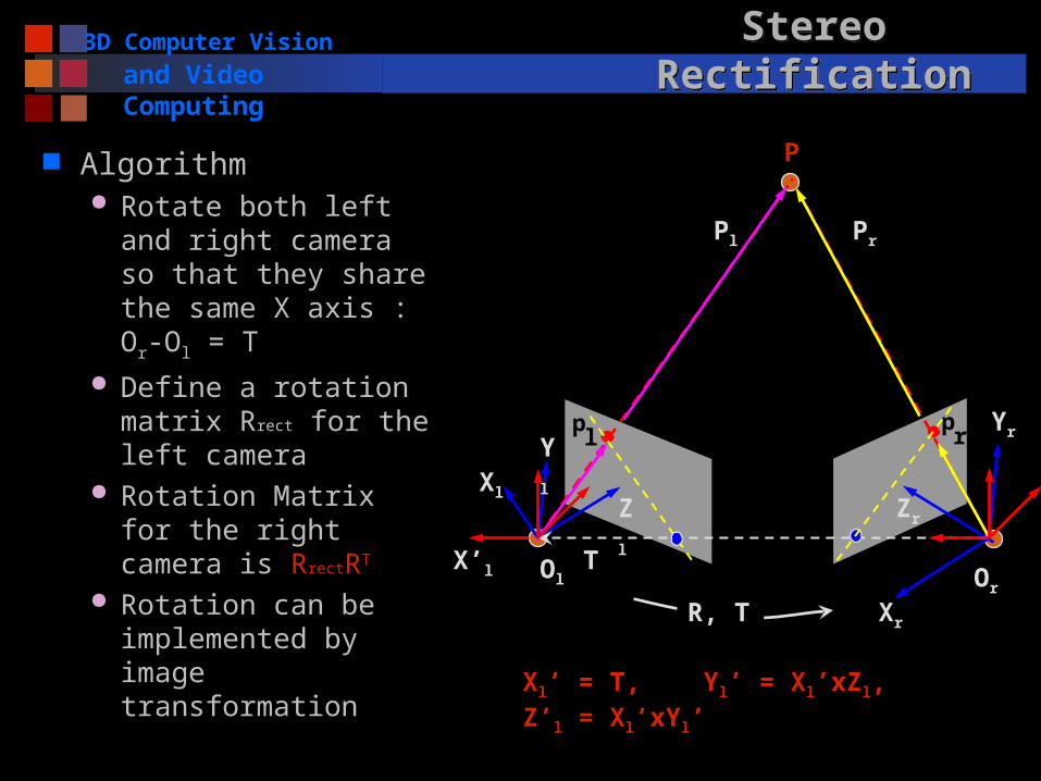
Algorithm Rotate both left and
right camera so that they share the same X axis : Or-Ol = T
Define a rotation matrix Rrect for the left camera
Rotation Matrix for the right camera is RrectRT
Rotation can be implemented by image transformation
pl
pr
P
Ol Or
Xl
Xr
Pl Pr
Zl
Yl
Zr
Yr
R, T
TX’l
Xl’ = T, Yl’ = Xl’xZl, Z’l = Xl’xYl’

3D Computer Vision
and Video Computing Stereo RectificationStereo Rectification
Algorithm Rotate both left and
right camera so that they share the same X axis : Or-Ol = T
Define a rotation matrix Rrect for the left camera
Rotation Matrix for the right camera is RrectRT
Rotation can be implemented by image transformation
Zr
p’lp’r
P
Ol Or
X’r
Pl Pr
Z’l
Y’l Y’r
R, T
TX’l
T’ = (B, 0, 0), P’r = P’l – T’

3D Computer Vision
and Video Computing Epipolar GeometryEpipolar Geometry
Purpose where to search correspondences
Epipolar plane, epipolar lines, and epipoles known intrinsic (f) and extrinsic (R, T)
co-planarity equation known intrinsic but unknown extrinsic
essential matrix unknown intrinsic and extrinsic
fundamental matrix
Rectification Generate stereo pair (by software) with parallel optical
axis and thus horizontal epipolar lines
0lTr Epp
0lTr pFp
0 lTT
r PTRP
3D Computer Vision
and Video Computing Correspondence problemCorrespondence problem
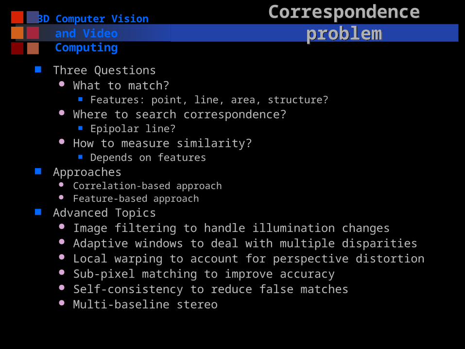
Three Questions What to match?
Features: point, line, area, structure? Where to search correspondence?
Epipolar line? How to measure similarity?
Depends on features Approaches
Correlation-based approach Feature-based approach
Advanced Topics Image filtering to handle illumination changes Adaptive windows to deal with multiple disparities Local warping to account for perspective distortion Sub-pixel matching to improve accuracy Self-consistency to reduce false matches Multi-baseline stereo
3D Computer Vision
and Video Computing Correlation ApproachCorrelation Approach
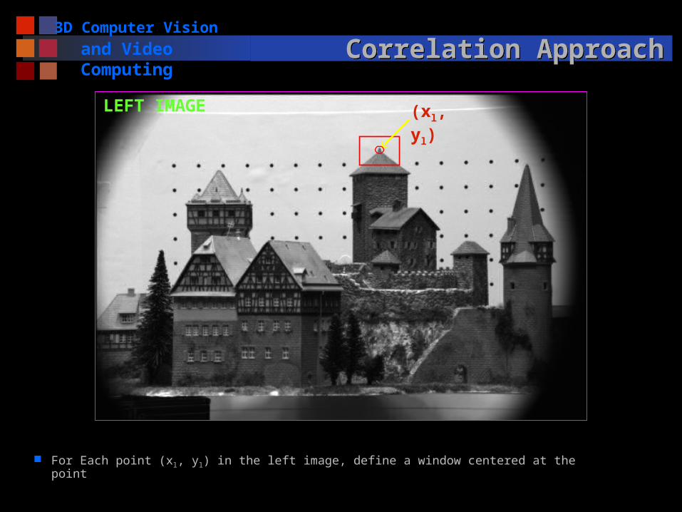
For Each point (xl, yl) in the left image, define a window centered at the point
(xl, yl)LEFT IMAGE

3D Computer Vision
and Video Computing Correlation ApproachCorrelation Approach
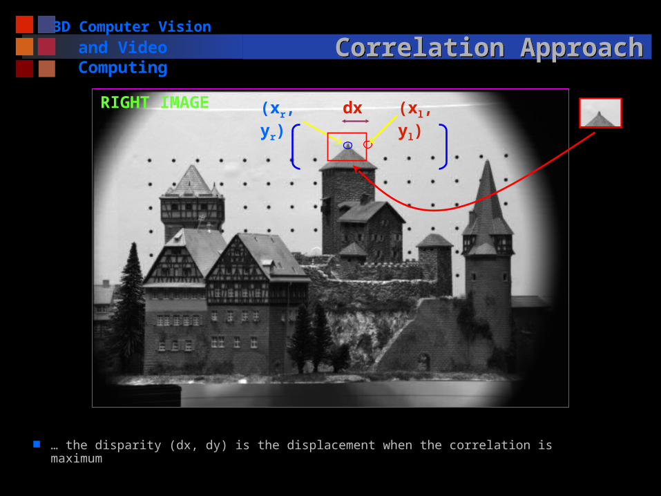
… search its corresponding point within a search region in the right image
(xl, yl)RIGHT IMAGE
3D Computer Vision
and Video Computing Correlation ApproachCorrelation Approach
… the disparity (dx, dy) is the displacement when the correlation is maximum
(xl, yl)dx(xr, yr)RIGHT IMAGE

3D Computer Vision
and Video Computing Correlation ApproachCorrelation Approach
Elements to be matched Image window of fixed size centered at each pixel in the
left image Similarity criterion
A measure of similarity between windows in the two images
The corresponding element is given by window that maximizes the similarity criterion within a search region
Search regions Theoretically, search region can be reduced to a 1-D
segment, along the epipolar line, and within the disparity range.
In practice, search a slightly larger region due to errors in calibration
3D Computer Vision
and Video Computing Correlation ApproachCorrelation Approach
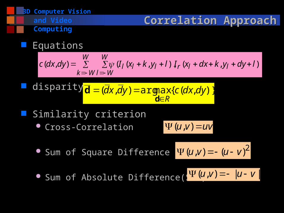
Equations
disparity
Similarity criterion Cross-Correlation
Sum of Square Difference (SSD)
Sum of Absolute Difference(SAD)
W
Wk
W
Wlllrlll ldyykdxxIlykxIdydxc )),(),,((),(
)},({maxarg),( dydxcydxdR
d
d
uvvu ),(
2)(),( vuvu
||),( vuvu

3D Computer Vision
and Video Computing Correlation ApproachCorrelation Approach
PROS Easy to implement Produces dense disparity map Maybe slow
CONS Needs textured images to work well Inadequate for matching image pairs from very different
viewpoints due to illumination changes Window may cover points with quite different disparities Inaccurate disparities on the occluding boundaries
3D Computer Vision
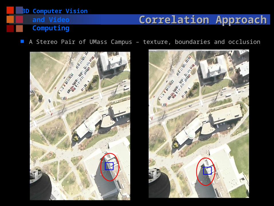
and Video Computing Correlation ApproachCorrelation Approach
A Stereo Pair of UMass Campus – texture, boundaries and occlusion
3D Computer Vision
and Video Computing Feature-based ApproachFeature-based Approach
Features Edge points Lines (length, orientation, average contrast) Corners
Matching algorithm Extract features in the stereo pair Define similarity measure Search correspondences using similarity measure and
the epipolar geometry

3D Computer Vision
and Video Computing Feature-based ApproachFeature-based Approach
For each feature in the left image…
LEFT IMAGE
corner line
structure
3D Computer Vision
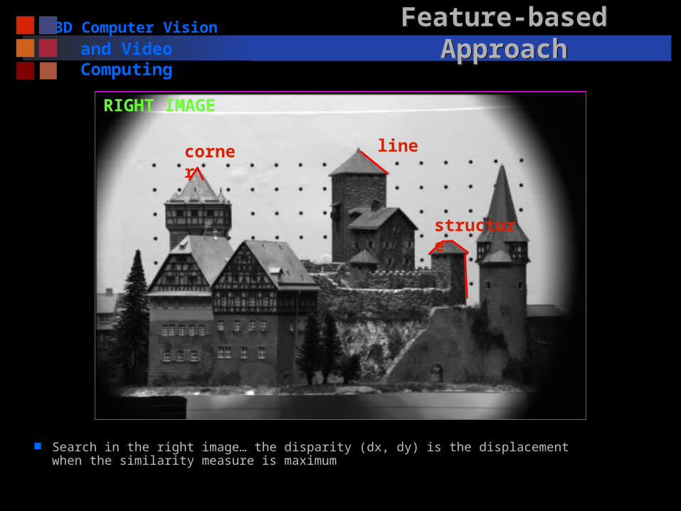
and Video Computing Feature-based ApproachFeature-based Approach
Search in the right image… the disparity (dx, dy) is the displacement when the similarity measure is maximum
RIGHT IMAGE
corner line
structure

3D Computer Vision
and Video Computing Feature-based ApproachFeature-based Approach
PROS Relatively insensitive to illumination changes Good for man-made scenes with strong lines but weak
texture or textureless surfaces Work well on the occluding boundaries (edges) Could be faster than the correlation approach
CONS Only sparse depth map Feature extraction may be tricky
Lines (Edges) might be partially extracted in one image How to measure the similarity between two lines?
3D Computer Vision
and Video Computing Advanced TopicsAdvanced Topics
Mainly used in correlation-based approach, but can be applied to feature-based match
Image filtering to handle illumination changes
Image equalization To make two images more similar in illumination
Laplacian filtering (2nd order derivative) Use derivative rather than intensity (or original color)
3D Computer Vision
and Video Computing Advanced TopicsAdvanced Topics
Adaptive windows to deal with multiple disparities Adaptive Window Approach (Kanade and Okutomi)
statistically adaptive technique which selects at each pixel the window size that minimizes the uncertainty in disparity estimates
A Stereo Matching Algorithm with an Adaptive Window: Theory and Experiment, T. Kanade and M. Okutomi. Proc. 1991 IEEE International Conference on Robotics and Automation, Vol. 2, April, 1991, pp. 1088-1095
Multiple window algorithm (Fusiello, et al) Use 9 windows instead of just one to compute the SSD
measure The point with the smallest SSD error amongst the 9
windows and various search locations is chosen as the best estimate for the given points
A Fusiello, V. Roberto and E. Trucco, Efficient stereo with multiple windowing, IEEE CVPR pp858-863, 1997

3D Computer Vision
and Video Computing Advanced TopicsAdvanced Topics Multiple windows to deal with multiple disparities
Smooth
regions
Corners
edges
near far

3D Computer Vision
and Video Computing Advanced TopicsAdvanced Topics
Sub-pixel matching to improve accuracy Find the peak in the correlation curves
Self-consistency to reduce false matches esp. for occlusions Check the consistency of matches from L to R and from R to L
Multiple Resolution Approach From coarse to fine for efficiency in searching correspondences
Local warping to account for perspective distortion Warp from one view to the other for a small patch given an
initial estimation of the (planar) surface normal
Multi-baseline Stereo Improves both correspondences and 3D estimation by using
more than two cameras (images)

3D Computer Vision
and Video Computing 3D Reconstruction Problem3D Reconstruction Problem
What we have done Correspondences using either correlation or feature
based approaches Epipolar Geometry from at least 8 point
correspondences Three cases of 3D reconstruction depending on the
amount of a priori knowledge on the stereo system Both intrinsic and extrinsic known - > can solve the
reconstruction problem unambiguously by triangulation Only intrinsic known -> recovery structure and extrinsic
up to an unknown scaling factor Only correspondences -> reconstruction only up to an
unknown, global projective transformation (*)

3D Computer Vision
and Video ComputingReconstruction by TriangulationReconstruction by Triangulation
Assumption and Problem Under the assumption that both
intrinsic and extrinsic parameters are known
Compute the 3-D location from their projections, pl and pr
Solution Triangulation: Two rays are
known and the intersection can be computed
Problem: Two rays will not actually intersect in space due to errors in calibration and correspondences, and pixelization
Solution: find a point in space with minimum distance from both rays
p pr
P
Ol Or
l
3D Computer Vision
and Video ComputingReconstruction up to a Scale FactorReconstruction up to a Scale Factor
Assumption and Problem Statement Under the assumption that only intrinsic parameters and
more than 8 point correspondences are given Compute the 3-D location from their projections, pl and pr, as
well as the extrinsic parameters Solution
Compute the essential matrix E from at least 8 correspondences
Estimate T (up to a scale and a sign) from E (=RS) using the orthogonal constraint of R, and then R
End up with four different estimates of the pair (T, R) Reconstruct the depth of each point, and pick up the correct
sign of R and T. Results: reconstructed 3D points (up to a common scale); The scale can be determined if distance of two points (in
space) are known

3D Computer Vision
and Video ComputingReconstruction up to a Projective TransformationReconstruction up to a Projective Transformation
Assumption and Problem Statement Under the assumption that only n (>=8) point
correspondences are given Compute the 3-D location from their projections, pl and
pr Solution
Compute the Fundamental matrix F from at least 8 correspondences, and the two epipoles
Determine the projection matrices Select five points ( from correspondence pairs) as the
projective basis Compute the projective reconstruction
Unique up to the unknown projective transformation fixed by the choice of the five points
(* not required for this course; needs advanced knowledge of projective geometry )
3D Computer Vision
and Video Computing SummarySummary
Fundamental concepts and problems of stereo Epipolar geometry and stereo rectification Estimation of fundamental matrix from 8 point pairs Correspondence problem and two techniques:
correlation and feature based matching Reconstruct 3-D structure from image
correspondences given Fully calibrated Partially calibration Uncalibrated stereo cameras (*)
3D Computer Vision
and Video Computing NextNext
Understanding 3D structure and events from motion
Motion