3Com Stackable Switch Advanced Config Guide
475
3Com Stackable Switch Family Advanced Configuration Guide 3Com Switch 5500 3Com Switch 5500G 3Com Switch 4500 3Com Switch 4200G 3Com Switch 4210 Manual Version: 20081010-C-1.01 www.3com.com 3Com Corporation 350 Campus Drive, Marlborough, MA, USA 01752 3064
-
Upload
12121213141213 -
Category
Documents
-
view
38 -
download
4
Transcript of 3Com Stackable Switch Advanced Config Guide

3Com Stackable Switch Family Advanced Configuration Guide
3Com Switch 5500 3Com Switch 5500G 3Com Switch 4500 3Com Switch 4200G 3Com Switch 4210
Manual Version: 20081010-C-1.01 www.3com.com 3Com Corporation 350 Campus Drive, Marlborough, MA, USA 01752 3064

Copyright © 2006-2008, 3Com Corporation. All rights reserved. No part of this documentation may be reproduced in any form or by any means or used to make any derivative work (such as translation, transformation, or adaptation) without written permission from 3Com Corporation.
3Com Corporation reserves the right to revise this documentation and to make changes in content from time to time without obligation on the part of 3Com Corporation to provide notification of such revision or change.
3Com Corporation provides this documentation without warranty, term, or condition of any kind, either implied or expressed, including, but not limited to, the implied warranties, terms or conditions of merchantability, satisfactory quality, and fitness for a particular purpose. 3Com may make improvements or changes in the product(s) and/or the program(s) described in this documentation at any time.
If there is any software on removable media described in this documentation, it is furnished under a license agreement included with the product as a separate document, in the hard copy documentation, or on the removable media in a directory file named LICENSE.TXT or !LICENSE.TXT. If you are unable to locate a copy, please contact 3Com and a copy will be provided to you.
UNITED STATES GOVERNMENT LEGEND
If you are a United States government agency, then this documentation and the software described herein are provided to you subject to the following:
All technical data and computer software are commercial in nature and developed solely at private expense. Software is delivered as “Commercial Computer Software” as defined in DFARS 252.227-7014 (June 1995) or as a “commercial item” as defined in FAR 2.101(a) and as such is provided with only such rights as are provided in 3Com’s standard commercial license for the Software. Technical data is provided with limited rights only as provided in DFAR 252.227-7015 (Nov 1995) or FAR 52.227-14 (June 1987), whichever is applicable. You agree not to remove or deface any portion of any legend provided on any licensed program or documentation contained in, or delivered to you in conjunction with, this User Guide.
Unless otherwise indicated, 3Com registered trademarks are registered in the United States and may or may not be registered in other countries.
3Com and the 3Com logo are registered trademarks of 3Com Corporation.
All other company and product names may be trademarks of the respective companies with which they are associated.
ENVIRONMENTAL STATEMENT
It is the policy of 3Com Corporation to be environmentally-friendly in all operations. To uphold our policy, we are committed to:
Establishing environmental performance standards that comply with national legislation and regulations.
Conserving energy, materials and natural resources in all operations.
Reducing the waste generated by all operations. Ensuring that all waste conforms to recognized environmental standards. Maximizing the recyclable and reusable content of all products.
Ensuring that all products can be recycled, reused and disposed of safely.
Ensuring that all products are labelled according to recognized environmental standards.
Improving our environmental record on a continual basis.
End of Life Statement
3Com processes allow for the recovery, reclamation and safe disposal of all end-of-life electronic components.
Regulated Materials Statement
3Com products do not contain any hazardous or ozone-depleting material.
Environmental Statement about the Documentation
The documentation for this product is printed on paper that comes from sustainable, managed forests; it is fully biodegradable and recyclable, and is completely chlorine-free. The varnish is environmentally-friendly, and the inks are vegetable-based with a low heavy-metal content.
About This Manual
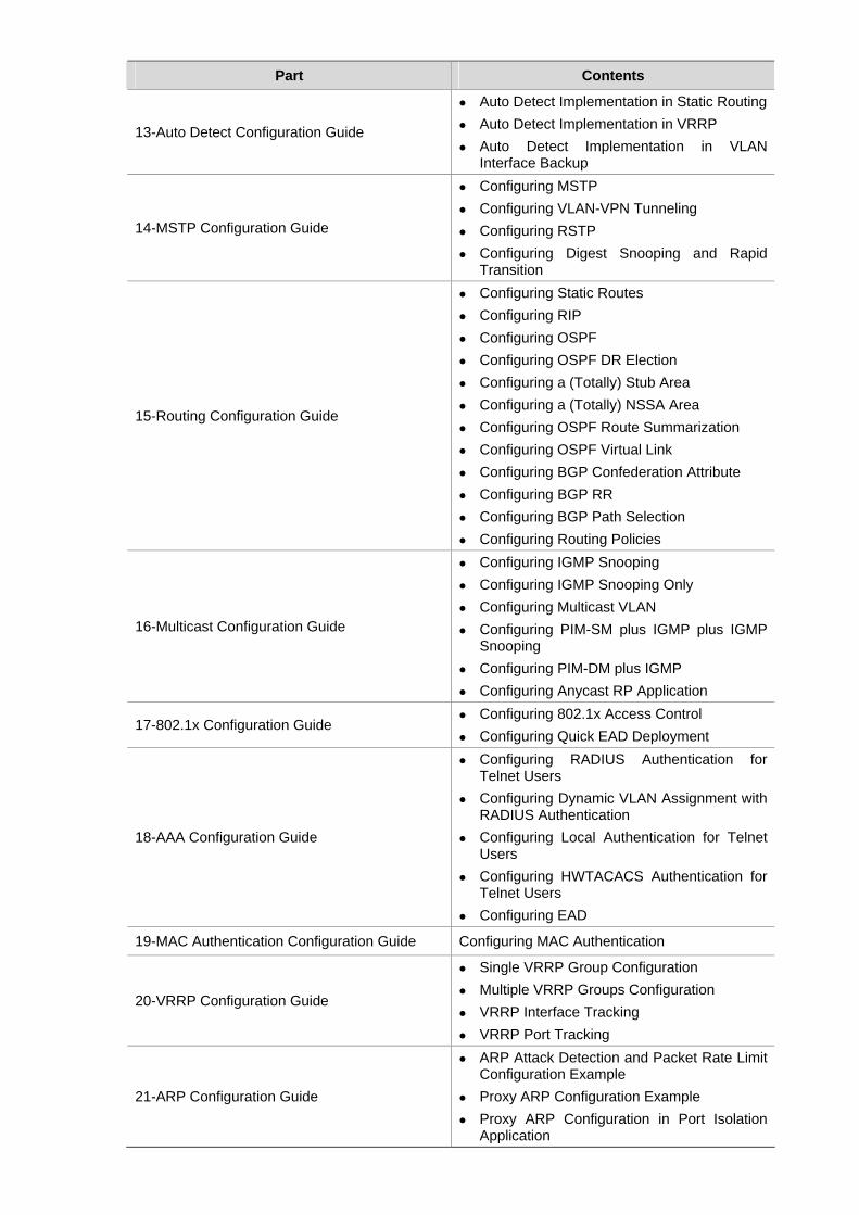
Provides advanced configuration examples for the 3Com stackable switches, which includes the following:
3Com Switch 5500
3Com Switch 5500G
3Com Switch 4500
3Com Switch 4200G
3Com Switch 4210
This guide is intended for Qualified Service personnel who are responsible for configuring, using, and managing the switches. It assumes a working knowledge of local area network (LAN) operations and familiarity with communication protocols that are used to interconnect LANs.
Always download the Release Notes for your product from the 3Com World Wide Web site and check for the latest updates to software and product documentation:
http://www.3com.com
Organization
3Com Stackable Switch Family Advanced Configuration Guide is organized as follows:
Part Contents
01-Login Configuration Guide Logging In from the Console Port Logging In Through Telnet Configuring Login Access Control
02-VLAN Configuration Guide Configuring Port-Based VLAN Configuring Protocol-Based VLAN
03-IP Address Configuration Guide IP Address Configuration Guide Sub IP Address Configuration Guide
04-Voice VLAN Configuration Guide Configuring Voice VLAN
05-GVRP Configuration Guide Configuring GVRP
06-Ethernet Interface Basic Configuration Guide Configuring the Basic Functions of an Ethernet Port
07-Link Aggregation Configuration Guide Configuring Link Aggregation
08-Port Isolation Configuration Guide Configuring Port Isolation
09-Port Security Configuration Guide
Configuring Port Security autolearn Mode Configuring Port Security mac-authentication
Mode Configuring Port Security userlogin-withoui
Mode Configuring Port Security
mac-else-userlogin-secure-ext Mode
10-Port Binding Configuration Guide Configuring a Port Binding
11-MAC Address Table Management Configuration Guide MAC Address Table Management
12-DLDP Configuration Guide Configuring DLDP
Part Contents
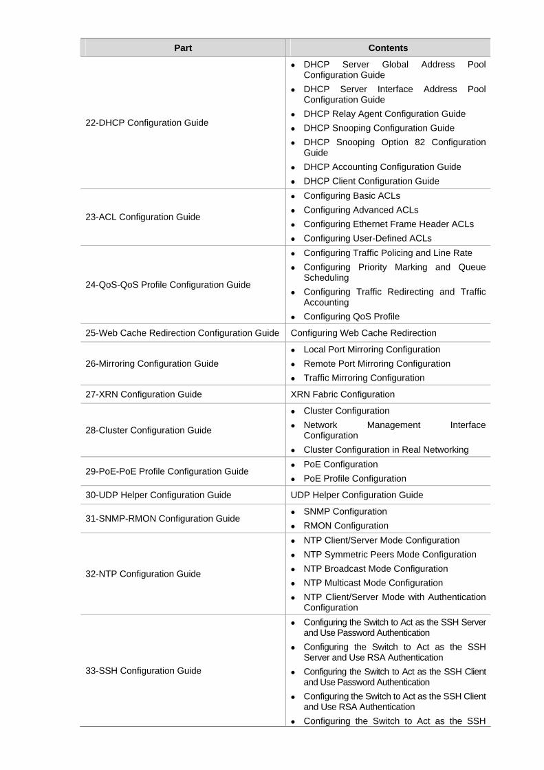
13-Auto Detect Configuration Guide
Auto Detect Implementation in Static Routing Auto Detect Implementation in VRRP Auto Detect Implementation in VLAN
Interface Backup
14-MSTP Configuration Guide
Configuring MSTP Configuring VLAN-VPN Tunneling Configuring RSTP Configuring Digest Snooping and Rapid
Transition
15-Routing Configuration Guide
Configuring Static Routes Configuring RIP Configuring OSPF Configuring OSPF DR Election Configuring a (Totally) Stub Area Configuring a (Totally) NSSA Area Configuring OSPF Route Summarization Configuring OSPF Virtual Link Configuring BGP Confederation Attribute Configuring BGP RR Configuring BGP Path Selection Configuring Routing Policies
16-Multicast Configuration Guide
Configuring IGMP Snooping Configuring IGMP Snooping Only Configuring Multicast VLAN Configuring PIM-SM plus IGMP plus IGMP
Snooping Configuring PIM-DM plus IGMP Configuring Anycast RP Application
17-802.1x Configuration Guide Configuring 802.1x Access Control Configuring Quick EAD Deployment
18-AAA Configuration Guide
Configuring RADIUS Authentication for Telnet Users
Configuring Dynamic VLAN Assignment with RADIUS Authentication
Configuring Local Authentication for Telnet Users
Configuring HWTACACS Authentication for Telnet Users
Configuring EAD
19-MAC Authentication Configuration Guide Configuring MAC Authentication
20-VRRP Configuration Guide
Single VRRP Group Configuration Multiple VRRP Groups Configuration VRRP Interface Tracking VRRP Port Tracking
21-ARP Configuration Guide
ARP Attack Detection and Packet Rate Limit Configuration Example
Proxy ARP Configuration Example Proxy ARP Configuration in Port Isolation
Application
Part Contents
22-DHCP Configuration Guide
DHCP Server Global Address Pool Configuration Guide
DHCP Server Interface Address Pool Configuration Guide
DHCP Relay Agent Configuration Guide DHCP Snooping Configuration Guide DHCP Snooping Option 82 Configuration
Guide DHCP Accounting Configuration Guide DHCP Client Configuration Guide
23-ACL Configuration Guide
Configuring Basic ACLs Configuring Advanced ACLs Configuring Ethernet Frame Header ACLs Configuring User-Defined ACLs
24-QoS-QoS Profile Configuration Guide
Configuring Traffic Policing and Line Rate Configuring Priority Marking and Queue
Scheduling Configuring Traffic Redirecting and Traffic
Accounting Configuring QoS Profile
25-Web Cache Redirection Configuration Guide Configuring Web Cache Redirection
26-Mirroring Configuration Guide Local Port Mirroring Configuration Remote Port Mirroring Configuration Traffic Mirroring Configuration
27-XRN Configuration Guide XRN Fabric Configuration
28-Cluster Configuration Guide
Cluster Configuration Network Management Interface
Configuration Cluster Configuration in Real Networking
29-PoE-PoE Profile Configuration Guide PoE Configuration PoE Profile Configuration
30-UDP Helper Configuration Guide UDP Helper Configuration Guide
31-SNMP-RMON Configuration Guide SNMP Configuration RMON Configuration
32-NTP Configuration Guide
NTP Client/Server Mode Configuration NTP Symmetric Peers Mode Configuration NTP Broadcast Mode Configuration NTP Multicast Mode Configuration NTP Client/Server Mode with Authentication
Configuration
33-SSH Configuration Guide
Configuring the Switch to Act as the SSH Server and Use Password Authentication
Configuring the Switch to Act as the SSH Server and Use RSA Authentication
Configuring the Switch to Act as the SSH Client and Use Password Authentication
Configuring the Switch to Act as the SSH Client and Use RSA Authentication
Configuring the Switch to Act as the SSH
Part Contents Client and Not to Support First-Time Authentication
Configuring SFTP When Switch Acts as Server for Password
Authentication When Switch Acts as Server for Publickey
Authentication When Switch Acts as Client for Password
Authentication When Switch Acts as Client for Publickey
Authentication When Switch Acts as Client and First-Time
Authentication is not Supported SFTP Configuration
34-FTP and TFTP Configuration Guide Configuring a Switch as FTP Server Configuring a Switch as FTP Client Configuring a Switch as TFTP Client
35-Information Center Configuration Guide
Outputting Log Information to a Unix Log Host
Outputting Log Information to a Linux Log Host
Outputting Log and Trap Information to a Log Host Through the Same Channel
Outputting Log Information to the Console Displaying the Time Stamp with the UTC
Time Zone Use of the Facility Argument in Log
Information Output
36-VLAN-VPN Configuration Guide Configuring VLAN-VPN Configuring Selective QinQ Configuring BPDU Tunnel
37-Remote-ping Configuration Guide Remote-ping Configuration
38-DNS Configuration Guide
Static Domain Name Resolution Configuration Guide
Dynamic Domain Name Resolution Configuration Guide
39-Access Management Configuration Guide Configuring Access Management Configuring Access Management with Port
Isolation
40-Web Authentication Configuration Guide Configuring Web Authentication
41-IPv6 Management Configuration Guide Configuring IPv6
42-Smart link - Monitor Link Configuration Guide Smart Link Configuration Example Implementing Collaboration Between Smart
Link and Monitor Link
43-VLAN Mapping Configuration Guide Configuring VLAN Mapping
Conventions
The manual uses the following conventions:
Command conventions
Convention Description
Boldface The keywords of a command line are in Boldface.
italic Command arguments are in italic.
# A line starting with the # sign is comments.
GUI conventions
Convention Description
Boldface Window names, button names, field names, and menu items are in Boldface. For example, the New User window appears; click OK.
Symbols
Convention Description
Means reader be careful. Improper operation may cause data loss or damage to equipment.
Means a complementary description.
Related Documentation
The following manuals offer additional information necessary for managing your Stackable Switch. Consult the documents that apply to the switch model that you are using.
Manual Description
3Com Switch Family Command Reference Guides
Provide detailed descriptions of command line interface (CLI) commands, that you require to manage your Stackable Switch.
3Com Switch Family Configuration Guides Describe how to configure your Stackable Switch using the supported protocols and CLI commands.
3Com Switch Family Quick Reference Guides Provide a summary of command line interface (CLI) commands that are required for you to manage your Stackable Switch.
3Com Stackable Switch Family Release Notes
Contain the latest information about your product. If information in this guide differs from information in the release notes, use the information in the Release Notes.
These documents are available in Adobe Acrobat Reader Portable Document Format (PDF) on the 3Com World Wide Web site: http://www.3com.com
Obtaining Documentation
You can access the most up-to-date 3Com product documentation on the World Wide Web at this URL: http://www.3com.com.
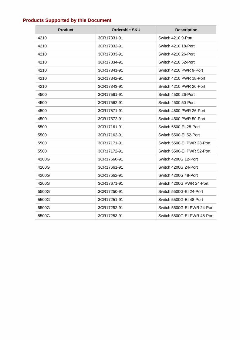
Products Supported by this Document
Product Orderable SKU Description
4210 3CR17331-91 Switch 4210 9-Port
4210 3CR17332-91 Switch 4210 18-Port
4210 3CR17333-91 Switch 4210 26-Port
4210 3CR17334-91 Switch 4210 52-Port
4210 3CR17341-91 Switch 4210 PWR 9-Port
4210 3CR17342-91 Switch 4210 PWR 18-Port
4210 3CR17343-91 Switch 4210 PWR 26-Port
4500 3CR17561-91 Switch 4500 26-Port
4500 3CR17562-91 Switch 4500 50-Port
4500 3CR17571-91 Switch 4500 PWR 26-Port
4500 3CR17572-91 Switch 4500 PWR 50-Port
5500 3CR17161-91 Switch 5500-EI 28-Port
5500 3CR17162-91 Switch 5500-EI 52-Port
5500 3CR17171-91 Switch 5500-EI PWR 28-Port
5500 3CR17172-91 Switch 5500-EI PWR 52-Port
4200G 3CR17660-91 Switch 4200G 12-Port
4200G 3CR17661-91 Switch 4200G 24-Port
4200G 3CR17662-91 Switch 4200G 48-Port
4200G 3CR17671-91 Switch 4200G PWR 24-Port
5500G 3CR17250-91 Switch 5500G-EI 24-Port
5500G 3CR17251-91 Switch 5500G-EI 48-Port
5500G 3CR17252-91 Switch 5500G-EI PWR 24-Port
5500G 3CR17253-91 Switch 5500G-EI PWR 48-Port
i
Table of Contents
1 Login Configuration Guide ·······················································································································1-1 Logging In from the Console Port ···········································································································1-1
Network Diagram·····························································································································1-1 Networking and Configuration Requirements··················································································1-1 Applicable Product Matrix················································································································1-1 Configuration Procedure··················································································································1-2 Complete Configuration···················································································································1-3 Precautions······································································································································1-3
Logging In Through Telnet······················································································································1-3 Network Diagram·····························································································································1-4 Networking and Configuration Requirements··················································································1-4 Applicable Product Matrix················································································································1-4 Configuration Procedure··················································································································1-4 Complete Configuration···················································································································1-5 Precautions······································································································································1-6
Configuring Login Access Control···········································································································1-6 Network Diagram·····························································································································1-6 Networking and Configuration Requirements··················································································1-6 Applicable Product Matrix················································································································1-6 Configuration Procedure··················································································································1-7 Complete Configuration···················································································································1-7 Precautions······································································································································1-8
1-1
1 Login Configuration Guide
Unless otherwise specified, all the switches used in the following configuration examples and configuration procedures are S5500 series switches (V03.03.01).
Logging In from the Console Port
You can log in locally from the console port to configure and maintain your switch, including configuring other login modes. The default login mode on the S5500 series is local console login.
Network Diagram
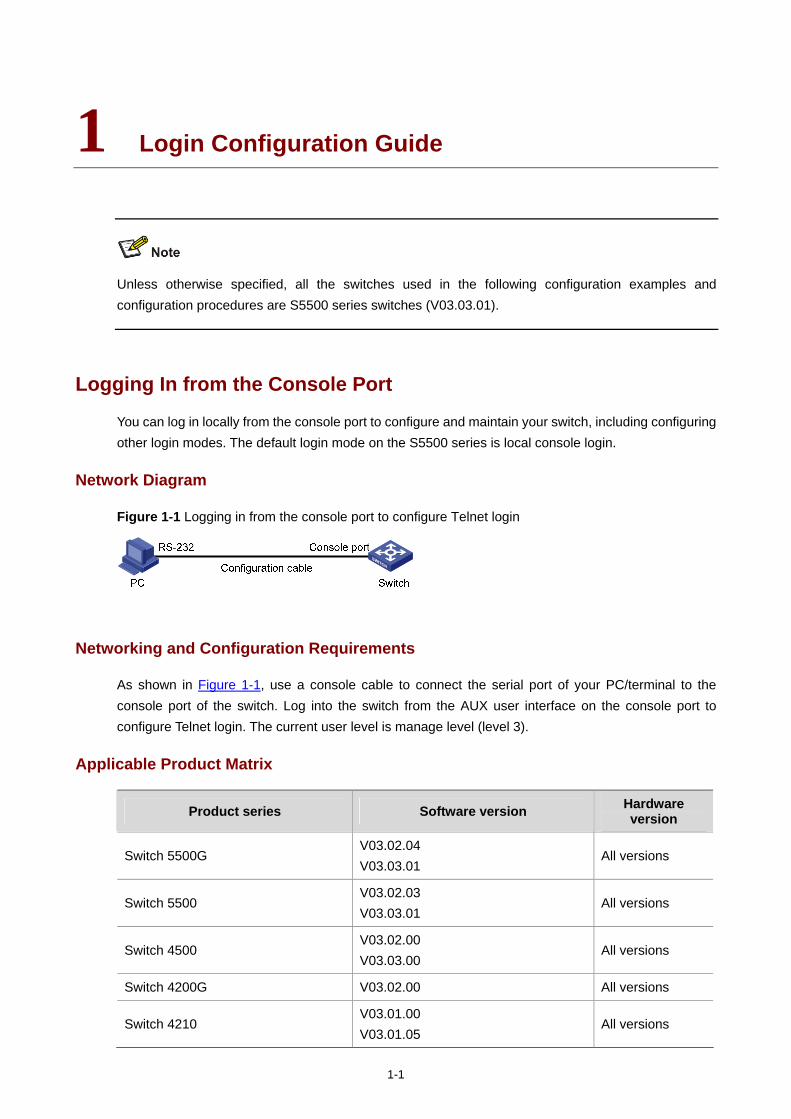
Figure 1-1 Logging in from the console port to configure Telnet login
Networking and Configuration Requirements
As shown in Figure 1-1, use a console cable to connect the serial port of your PC/terminal to the console port of the switch. Log into the switch from the AUX user interface on the console port to configure Telnet login. The current user level is manage level (level 3).
Applicable Product Matrix
Product series Software version Hardware version
Switch 5500G V03.02.04 V03.03.01
All versions
Switch 5500 V03.02.03 V03.03.01
All versions
Switch 4500 V03.02.00 V03.03.00
All versions
Switch 4200G V03.02.00 All versions
Switch 4210 V03.01.00 V03.01.05
All versions
1-2
Configuration Procedure
Configure common attributes for Telnet login
# Set the level of commands accessible to the VTY 0 user to 2.
[Sysname] user-interface vty 0
[Sysname-ui-vty0] user privilege level 2
# Enable the Telnet service on VTY 0.
[Sysname-ui-vty0] protocol inbound telnet
# Set the number of lines that can be viewed on the screen of the VTY 0 user to 30.
[Sysname-ui-vty0] screen-length 30
# Set the history command buffer size to 20 for VTY 0.
[Sysname-ui-vty0] history-command max-size 20
# Set the idle-timeout time of VTY 0 to 6 minutes.
[Sysname-ui-vty0] idle-timeout 6
Configure an authentication mode for Telnet login
The following three authentication modes are available for Telnet login: none, password, and scheme.
The configuration procedures for the three authentication modes are described below:
1) Configure not to authenticate Telnet users on VTY 0. [Sysname] user-interface vty 0
[Sysname-ui-vty0] authentication-mode none
2) Configure password authentication for Telnet login on VTY 0, and set the password to 123456 in plain text.
[Sysname] user-interface vty 0
[Sysname-ui-vty0] authentication-mode password
[Sysname-ui-vty0] set authentication password simple 123456
3) Configure local authentication in scheme mode for login users.
# Create a local user named guest and enter local user view.
[Sysname] local-user guest
# Set the authentication password to 123456 in plain text.
[Sysname-luser-guest] password simple 123456
# Set the service type to Telnet and the user level to 2 for the user guest.
[Sysname-luser-guest] service-type telnet level 2
[Sysname-luser-guest] quit
# Enter VTY 0 user interface view.
[Sysname] user-interface vty 0
# Set the authentication mode to scheme for Telnet login on VTY 0.
[Sysname-ui-vty0] authentication-mode scheme
[Sysname-ui-vty0] quit
# Specify the domain system as the default domain, and configure the domain to adopt local authentication in scheme mode.
[Sysname] domain default enable system
1-3
[Sysname] domain system
[Sysname-isp-system] scheme local
Complete Configuration
Telnet login configuration with the authentication mode being none user-interface vty 0
authentication-mode none
user privilege level 2
history-command max-size 20
idle-timeout 6 0
screen-length 30
protocol inbound telnet
Telnet login configuration with the authentication mode being password user-interface vty 0
user privilege level 2
set authentication password simple 123456
history-command max-size 20
idle-timeout 6 0
screen-length 30
protocol inbound telnet
Telnet login configuration with the authentication mode being scheme #
domain system
#
local-user guest
password simple 123456
level 2
#
user-interface vty 0
authentication-mode scheme
user privilege level 2
history-command max-size 20
idle-timeout 6 0
screen-length 30
protocol inbound telnet
Precautions
None
Logging In Through Telnet
You can telnet to your switch to manage and maintain it remotely.
1-4
Network Diagram
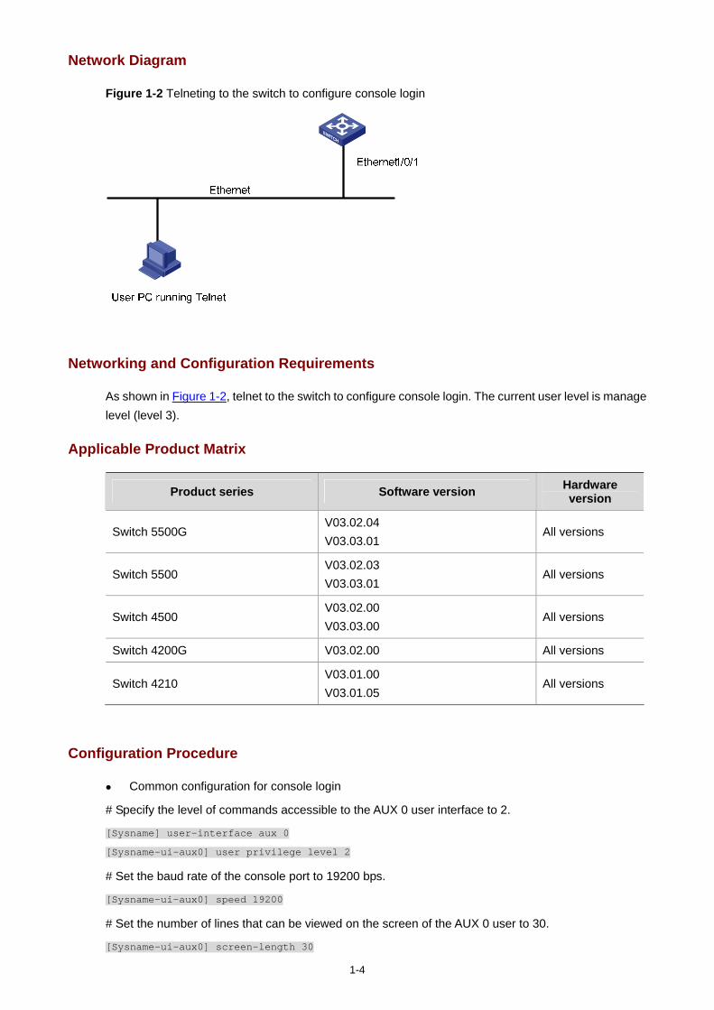
Figure 1-2 Telneting to the switch to configure console login
Networking and Configuration Requirements
As shown in Figure 1-2, telnet to the switch to configure console login. The current user level is manage level (level 3).
Applicable Product Matrix
Product series Software version Hardware version
Switch 5500G V03.02.04 V03.03.01
All versions
Switch 5500 V03.02.03 V03.03.01
All versions
Switch 4500 V03.02.00 V03.03.00
All versions
Switch 4200G V03.02.00 All versions
Switch 4210 V03.01.00 V03.01.05
All versions
Configuration Procedure
Common configuration for console login
# Specify the level of commands accessible to the AUX 0 user interface to 2.
[Sysname] user-interface aux 0
[Sysname-ui-aux0] user privilege level 2
# Set the baud rate of the console port to 19200 bps.
[Sysname-ui-aux0] speed 19200
# Set the number of lines that can be viewed on the screen of the AUX 0 user to 30.
[Sysname-ui-aux0] screen-length 30
1-5
# Set the history command buffer size to 20 for AUX 0.
[Sysname-ui-aux0] history-command max-size 20
# Set the idle-timeout time of AUX 0 to 6 minutes.
[Sysname-ui-aux0] idle-timeout 6
Configure the authentication mode for console login
The following three authentication modes are available for console login: none, password, and scheme. The configuration procedures for the three authentication modes are described below:
1) Configure not to authenticate console login users. [Sysname] user-interface aux 0
[Sysname-ui-aux0] authentication-mode none
2) Configure password authentication for console login, and set the password to 123456 in plain text. [Sysname] user-interface aux 0
[Sysname-ui-aux0] authentication-mode password
[Sysname-ui-aux0] set authentication password simple 123456
3) Configure local authentication in scheme mode for console login.
# Create a local user named guest and enter local user view.
[Sysname] local-user guest
# Set the authentication password to 123456 in plain text.
[Sysname-luser-guest] password simple 123456
# Set the service type to Terminal and the user level to 2 for the user guest.
[Sysname-luser-guest] service-type terminal level 2
[Sysname-luser-guest] quit
# Enter AUX 0 user interface view.
[Sysname] user-interface aux 0
# Set the authentication mode to scheme for console login.
[Sysname-ui-aux0] authentication-mode scheme
Complete Configuration
Console login configuration with the authentication mode being none #
user-interface aux 0
user privilege level 2
history-command max-size 20
idle-timeout 6 0
speed 19200
screen-length 30
Console login configuration with the authentication mode being password #
user-interface aux 0
authentication-mode password
user privilege level 2
set authentication password simple 123456
history-command max-size 20
1-6
idle-timeout 6 0
speed 19200
screen-length 30
Console login configuration with the authentication mode being scheme #
local-user guest
password simple 123456
service-type terminal
level 2
#
user-interface aux 0
authentication-mode scheme
user privilege level 2
history-command max-size 20
idle-timeout 6 0
speed 19200
screen-length 30
Precautions
None
Configuring Login Access Control
Network Diagram
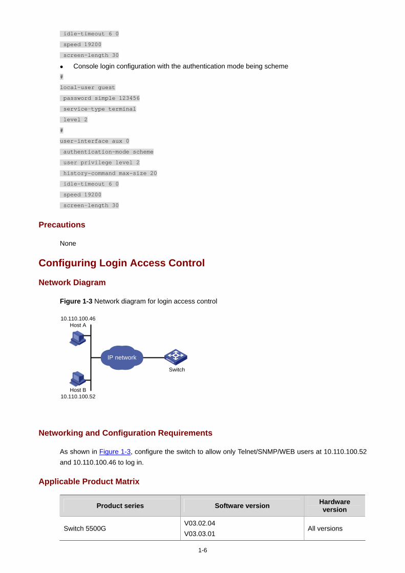
Figure 1-3 Network diagram for login access control
Switch
10.110.100.46Host A
IP network
Host B10.110.100.52
Networking and Configuration Requirements
As shown in Figure 1-3, configure the switch to allow only Telnet/SNMP/WEB users at 10.110.100.52 and 10.110.100.46 to log in.
Applicable Product Matrix
Product series Software version Hardware version
Switch 5500G V03.02.04 V03.03.01
All versions
1-7
Product series Software version Hardware version
Switch 5500 V03.02.03 V03.03.01
All versions
Switch 4500 V03.02.00 V03.03.00
All versions
Switch 4200G V03.02.00 All versions
Switch 4210 V03.01.00 V03.01.05
All versions
Configuration Procedure
# Create basic ACL 2000 and enter basic ACL view.
[Sysname] acl number 2000 match-order config
[Sysname-acl-basic-2000]
# Define ACL rules to allow only Telnet/SNMP/WEB users at 10.110.100.52 and 10.110.100.46 to log into the switch.
[Sysname-acl-basic-2000] rule 1 permit source 10.110.100.52 0
[Sysname-acl-basic-2000] rule 2 permit source 10.110.100.46 0
[Sysname-acl-basic-2000] rule 3 deny source any
[Sysname-acl-basic-2000] quit
# Reference ACL 2000 to control Telnet login by source IP address.
[Sysname] user-interface vty 0 4
[Sysname-ui-vty0-4] acl 2000 inbound
# Reference ACL 2000 to control SNMP login by source IP address.
[Sysname] snmp-agent community read aaa acl 2000
[Sysname] snmp-agent group v2c groupa acl 2000
[Sysname] snmp-agent usm-user v2c usera groupa acl 2000
# Reference ACL 2000 to control WEB login by source IP address.
[Sysname] ip http acl 2000
Complete Configuration
Configuration for Telnet login control by source IP address #
acl number 2000
rule 1 permit source 10.110.100.52 0
rule 2 permit source 10.110.100.46 0
rule 3 deny
#
user-interface vty 0 4
acl 2000 inbound
Configuration for SNMP login control by source IP address #
1-8
acl number 2000
rule 1 permit source 10.110.100.52 0
rule 2 permit source 10.110.100.46 0
rule 3 deny
#
snmp-agent community read aaa acl 2000
snmp-agent group v2c groupa acl 2000
snmp-agent usm-user v2c usera groupa acl 2000
Configuration for WEB login control by source IP address #
ip http acl 2000
#
acl number 2000
rule 1 permit source 10.110.100.52 0
rule 2 permit source 10.110.100.46 0
rule 3 deny
Precautions
None
i
Table of Contents
1 VLAN Configuration Guide ·······················································································································1-1 Configuring Port-Based VLAN ················································································································1-1
Network Diagram·····························································································································1-1 Networking and Configuration Requirements··················································································1-1 Applicable Product Matrix················································································································1-2 Configuration Procedure··················································································································1-2 Complete Configuration···················································································································1-3 Precautions······································································································································1-4
Configuring Protocol-Based VLAN··········································································································1-4 Network Diagram·····························································································································1-5 Networking and Configuration Requirements··················································································1-5 Applicable Product Matrix················································································································1-5 Configuration Procedure··················································································································1-5 Complete Configuration···················································································································1-6 Precautions······································································································································1-7
1-1
1 VLAN Configuration Guide
Configuring Port-Based VLAN
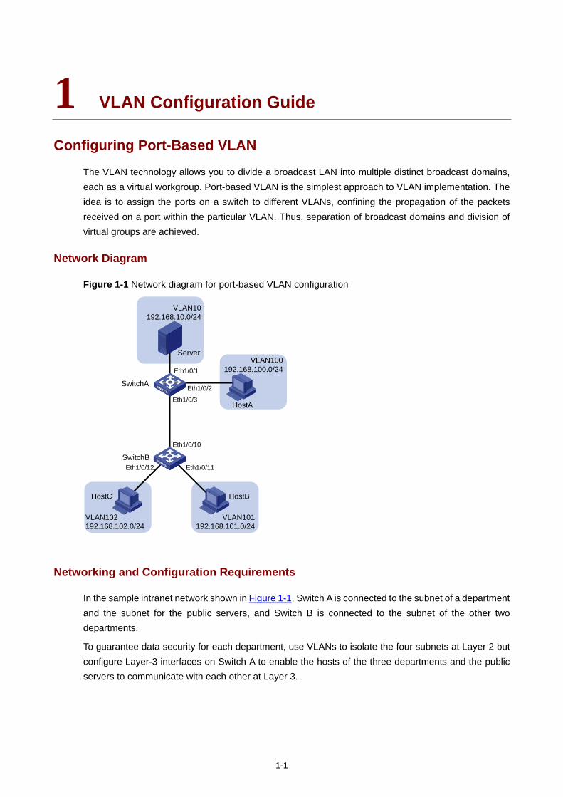
The VLAN technology allows you to divide a broadcast LAN into multiple distinct broadcast domains, each as a virtual workgroup. Port-based VLAN is the simplest approach to VLAN implementation. The idea is to assign the ports on a switch to different VLANs, confining the propagation of the packets received on a port within the particular VLAN. Thus, separation of broadcast domains and division of virtual groups are achieved.
Network Diagram
Figure 1-1 Network diagram for port-based VLAN configuration
VLAN10192.168.10.0/24
VLAN101192.168.101.0/24
SwitchA
SwitchB
VLAN100192.168.100.0/24
Eth1/0/2
Eth1/0/1
Eth1/0/3
Eth1/0/10
Eth1/0/12 Eth1/0/11
VLAN102192.168.102.0/24
HostA
HostBHostC
Server
Networking and Configuration Requirements
In the sample intranet network shown in Figure 1-1, Switch A is connected to the subnet of a department and the subnet for the public servers, and Switch B is connected to the subnet of the other two departments.
To guarantee data security for each department, use VLANs to isolate the four subnets at Layer 2 but configure Layer-3 interfaces on Switch A to enable the hosts of the three departments and the public servers to communicate with each other at Layer 3.
1-2
Applicable Product Matrix
Product series Software version Hardware version
Switch 5500G V03.02.04 V03.03.01
All versions
Switch 4200G V03.02.00 All versions
Switch 5500 V03.02.03 V03.03.01
All versions
Switch 4500 V03.02.00 V03.03.00
All versions
Switch 4210 V03.01.00 V03.01.05
All versions
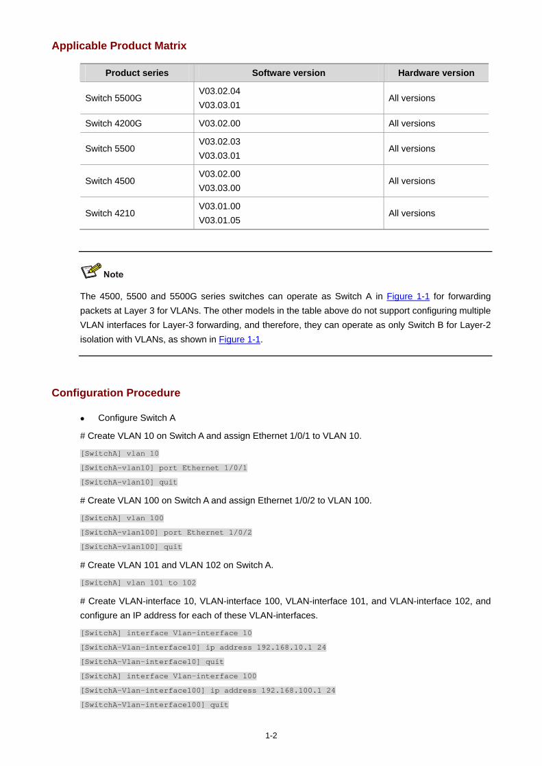
The 4500, 5500 and 5500G series switches can operate as Switch A in Figure 1-1 for forwarding packets at Layer 3 for VLANs. The other models in the table above do not support configuring multiple VLAN interfaces for Layer-3 forwarding, and therefore, they can operate as only Switch B for Layer-2 isolation with VLANs, as shown in Figure 1-1.
Configuration Procedure
Configure Switch A
# Create VLAN 10 on Switch A and assign Ethernet 1/0/1 to VLAN 10.
[SwitchA] vlan 10
[SwitchA-vlan10] port Ethernet 1/0/1
[SwitchA-vlan10] quit
# Create VLAN 100 on Switch A and assign Ethernet 1/0/2 to VLAN 100.
[SwitchA] vlan 100
[SwitchA-vlan100] port Ethernet 1/0/2
[SwitchA-vlan100] quit
# Create VLAN 101 and VLAN 102 on Switch A.
[SwitchA] vlan 101 to 102
# Create VLAN-interface 10, VLAN-interface 100, VLAN-interface 101, and VLAN-interface 102, and configure an IP address for each of these VLAN-interfaces.
[SwitchA] interface Vlan-interface 10
[SwitchA-Vlan-interface10] ip address 192.168.10.1 24
[SwitchA-Vlan-interface10] quit
[SwitchA] interface Vlan-interface 100
[SwitchA-Vlan-interface100] ip address 192.168.100.1 24
[SwitchA-Vlan-interface100] quit
1-3
[SwitchA] interface Vlan-interface 101
[SwitchA-Vlan-interface101] ip address 192.168.101.1 24
[SwitchA-Vlan-interface101] quit
[SwitchA] interface Vlan-interface 102
[SwitchA-Vlan-interface102] ip address 192.168.102.1 24
[SwitchA-Vlan-interface102] quit
# Configure Ethernet 1/0/3 of Switch A to be a trunk port and to permit the packets carrying the tag of VLAN 101 or VLAN 102 to pass through.
[SwitchA] interface Ethernet 1/0/3
[SwitchA-Ethernet1/0/3] port link-type trunk
[SwitchA-Ethernet1/0/3] port trunk permit vlan 101 102
Configure Switch B
# Create VLAN 101 on Switch B, and assign Ethernet 1/0/11 to VLAN 101.
[SwitchB] vlan 101
[SwitchB-vlan101] port Ethernet 1/0/11
[SwitchB-vlan101] quit
# Create VLAN 102 on Switch B, and assign Ethernet 1/0/12 to VLAN 102.
[SwitchB] vlan 102
[SwitchB-vlan102] port Ethernet 1/0/12
[SwitchB-vlan102] quit
# Configure Ethernet 1/0/10 of Switch B to be a trunk port and to permit the packets carrying the tag of VLAN 101 or VLAN 102 to pass through.
[SwitchB] interface Ethernet 1/0/10
[SwitchB-Ethernet1/0/10] port link-type trunk
[SwitchB-Ethernet1/0/10] port trunk permit vlan 101 102
Complete Configuration
Configuration on Switch A #
vlan 10
#
vlan 100
#
vlan 101
#
vlan 102
#
interface Vlan-interface 10
ip address 192.168.10.1 255.255.255.0
#
interface Vlan-interface 100
ip address 192.168.100.1 255.255.255.0
#
interface Vlan-interface 101
ip address 192.168.101.1 255.255.255.0
1-4
#
interface Vlan-interface 102
ip address 192.168.102.1 255.255.255.0
#
interface Ethernet1/0/1
port access vlan 10
#
interface Ethernet1/0/2
port access vlan 100
#
interface Ethernet1/0/3
port link-type trunk
port trunk permit vlan 1 101 102
Configuration on Switch B #
vlan 101
#
vlan 102
#
interface Ethernet1/0/10
port link-type trunk
port trunk permit vlan 1 101 102
#
interface Ethernet1/0/11
port access vlan 101
#
interface Ethernet1/0/12
port access vlan 201
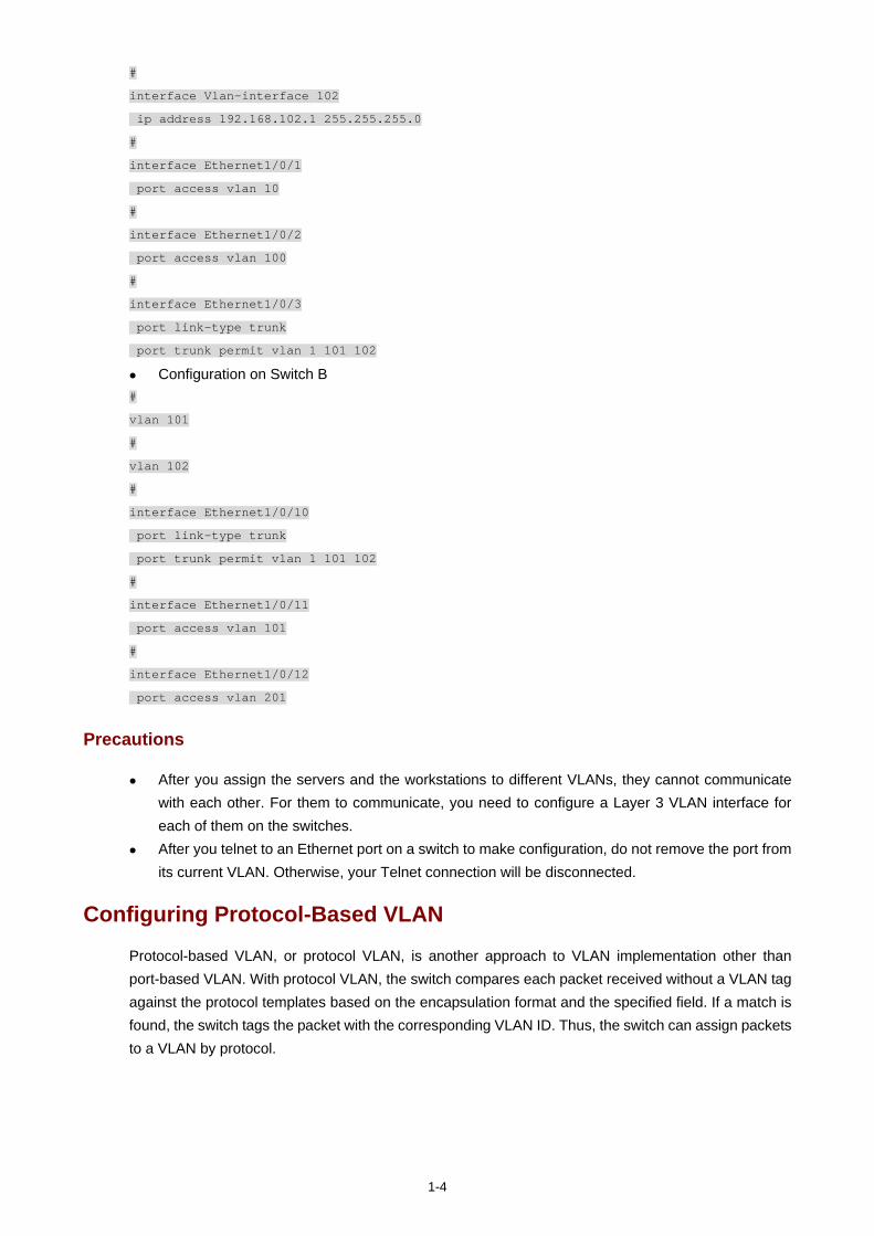
Precautions
After you assign the servers and the workstations to different VLANs, they cannot communicate with each other. For them to communicate, you need to configure a Layer 3 VLAN interface for each of them on the switches.
After you telnet to an Ethernet port on a switch to make configuration, do not remove the port from its current VLAN. Otherwise, your Telnet connection will be disconnected.
Configuring Protocol-Based VLAN
Protocol-based VLAN, or protocol VLAN, is another approach to VLAN implementation other than port-based VLAN. With protocol VLAN, the switch compares each packet received without a VLAN tag against the protocol templates based on the encapsulation format and the specified field. If a match is found, the switch tags the packet with the corresponding VLAN ID. Thus, the switch can assign packets to a VLAN by protocol.
1-5
Network Diagram
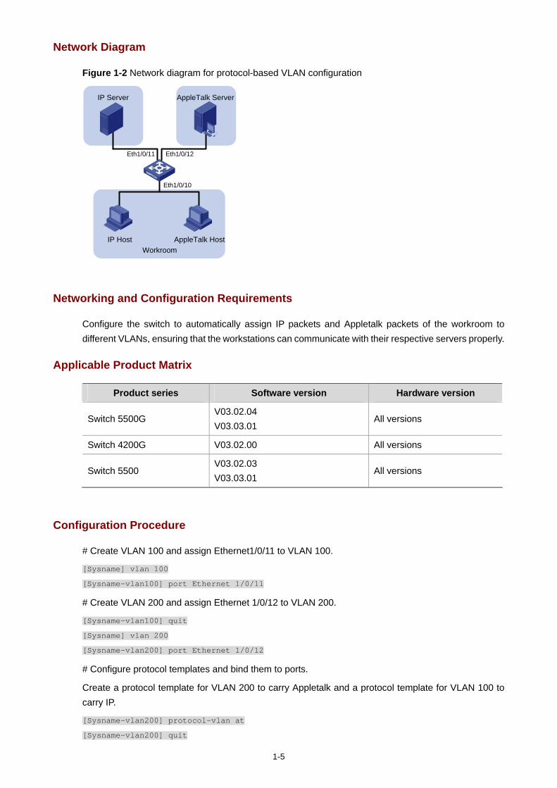
Figure 1-2 Network diagram for protocol-based VLAN configuration
IP Host
Eth1/0/10
Eth1/0/11 Eth1/0/12
WorkroomAppleTalk Host
IP Server AppleTalk Server
Networking and Configuration Requirements
Configure the switch to automatically assign IP packets and Appletalk packets of the workroom to different VLANs, ensuring that the workstations can communicate with their respective servers properly.
Applicable Product Matrix
Product series Software version Hardware version
Switch 5500G V03.02.04 V03.03.01
All versions
Switch 4200G V03.02.00 All versions
Switch 5500 V03.02.03 V03.03.01
All versions
Configuration Procedure
# Create VLAN 100 and assign Ethernet1/0/11 to VLAN 100.
[Sysname] vlan 100
[Sysname-vlan100] port Ethernet 1/0/11
# Create VLAN 200 and assign Ethernet 1/0/12 to VLAN 200.
[Sysname-vlan100] quit
[Sysname] vlan 200
[Sysname-vlan200] port Ethernet 1/0/12
# Configure protocol templates and bind them to ports.
Create a protocol template for VLAN 200 to carry Appletalk and a protocol template for VLAN 100 to carry IP.
[Sysname-vlan200] protocol-vlan at
[Sysname-vlan200] quit
1-6
[Sysname] vlan 100
[Sysname-vlan100] protocol-vlan ip
Create a user-defined protocol template for VLAN 100 to carry ARP for IP communication, assuming that Ethernet_II encapsulation is used.
[Sysname-vlan100] protocol-vlan mode ethernetii etype 0806
Configure Ethernet 1/0/10 to be a hybrid port and to remove the outer VLAN tag when forwarding packets of VLAN 100 and VLAN 200.
[Sysname-vlan100] quit
[Sysname] interface Ethernet 1/0/10
[Sysname-Ethernet1/0/10] port link-type hybrid
[Sysname-Ethernet1/0/10] port hybrid vlan 100 200 untagged
Bind Ethernet 1/0/10 to protocol template 0 and protocol template 1 of VLAN 100, and protocol template 0 of VLAN 200.
When configuring a protocol template, you can assign a number to the template. If you fail to do that, the system automatically assigns the lowest available number to the template. Thus, in this configuration example, the two protocol templates for VLAN 100 are automatically numbered 0 and 1, and the protocol template for VLAN 200 is numbered 0.
[Sysname-Ethernet1/0/10] port hybrid protocol-vlan vlan 100 0 to 1
[Sysname-Ethernet1/0/10] port hybrid protocol-vlan vlan 200 0
Complete Configuration
#
vlan 100
protocol-vlan 0 ip
protocol-vlan 1 mode ethernetii etype 0806
#
vlan 200
protocol-vlan 0 at
#
interface Ethernet1/0/10
port link-type hybrid
port hybrid vlan 1 100 200 untagged
port hybrid protocol-vlan vlan 100 0
port hybrid protocol-vlan vlan 100 1
port hybrid protocol-vlan vlan 200 0
#
interface Ethernet1/0/11
port access vlan 100
#
interface Ethernet1/0/12
port access vlan 200

1-7
Precautions
Because IP depends on ARP for address resolution in Ethernet, you are recommended to configure the IP and ARP templates in the same VLAN and associate them with the same port to prevent communication failure.

i
Table of Contents
1 IP Address Configuration Guide ··············································································································1-1 IP Address Configuration Guide ·············································································································1-1
Network Diagram·····························································································································1-1 Networking and Configuration Requirements··················································································1-1 Applicable Product Matrix················································································································1-1 Configuration Procedure··················································································································1-2 Complete Configuration···················································································································1-2 Precautions······································································································································1-2
Sub IP Address Configuration Guide ······································································································1-2 Network Diagram·····························································································································1-2 Networking and Configuration Requirements··················································································1-2 Applicable Product Matrix················································································································1-3 Configuration Procedure··················································································································1-3 Complete Configuration···················································································································1-3 Precautions······································································································································1-3
1-1
1 IP Address Configuration Guide
IP Address Configuration Guide
IP addressing uses a 32-bit address to identify each host on a network. An example is 01010000100000001000000010000000 in binary. To make IP addresses in 32-bit form easier to read, they are written in dotted decimal notation, each being four octets in length, for example, 10.1.1.1 for the address just mentioned.
If you want to manage a remote Ethernet switch through network management or telnet, you need to configure an IP address for the remote switch and ensure that the local device and the remote switch are reachable to each other.
Network Diagram
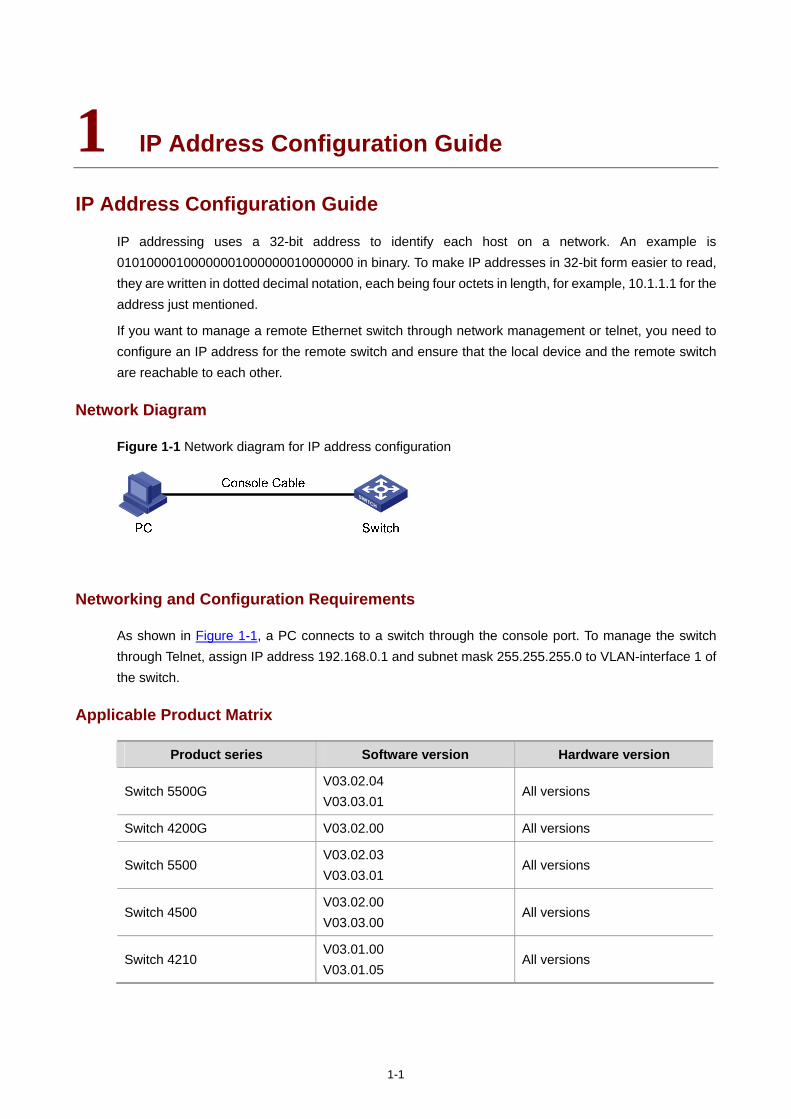
Figure 1-1 Network diagram for IP address configuration
Networking and Configuration Requirements
As shown in Figure 1-1, a PC connects to a switch through the console port. To manage the switch through Telnet, assign IP address 192.168.0.1 and subnet mask 255.255.255.0 to VLAN-interface 1 of the switch.
Applicable Product Matrix
Product series Software version Hardware version
Switch 5500G V03.02.04 V03.03.01
All versions
Switch 4200G V03.02.00 All versions
Switch 5500 V03.02.03 V03.03.01
All versions
Switch 4500 V03.02.00 V03.03.00
All versions
Switch 4210 V03.01.00 V03.01.05
All versions
1-2
Configuration Procedure
# Configure the switch through the console port (omitted).
# Assign the IP address to VLAN-interface 1.
<Switch> system-view
[Switch] interface Vlan-interface 1
[Switch-Vlan-interface1] ip address 192.168.0.1 255.255.255.0
Complete Configuration
#
interface Vlan-interface 1
ip address 192.168.0.1 255.255.255.0
#
Precautions
Besides directly assigning an IP address to a VLAN interface, you may configure a VLAN interface to obtain an IP address through BOOTP or DHCP as alternatives. If you change the way an interface obtains an IP address, from manual assignment to BOOTP for example, the IP address obtained from BOOTP will overwrite the old one manually assigned.
Sub IP Address Configuration Guide
Network Diagram
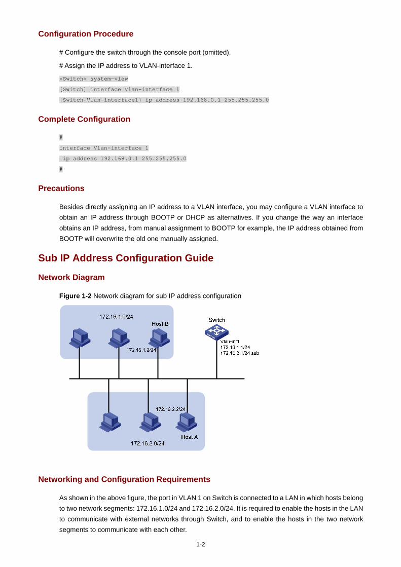
Figure 1-2 Network diagram for sub IP address configuration
Networking and Configuration Requirements
As shown in the above figure, the port in VLAN 1 on Switch is connected to a LAN in which hosts belong to two network segments: 172.16.1.0/24 and 172.16.2.0/24. It is required to enable the hosts in the LAN to communicate with external networks through Switch, and to enable the hosts in the two network segments to communicate with each other.
1-3
Applicable Product Matrix
Product series Software version Hardware version
Switch 5500G V03.02.04 V03.03.01
All versions
Switch 4200G V03.02.00 All versions
Switch 5500 V03.02.03 V03.03.01
All versions
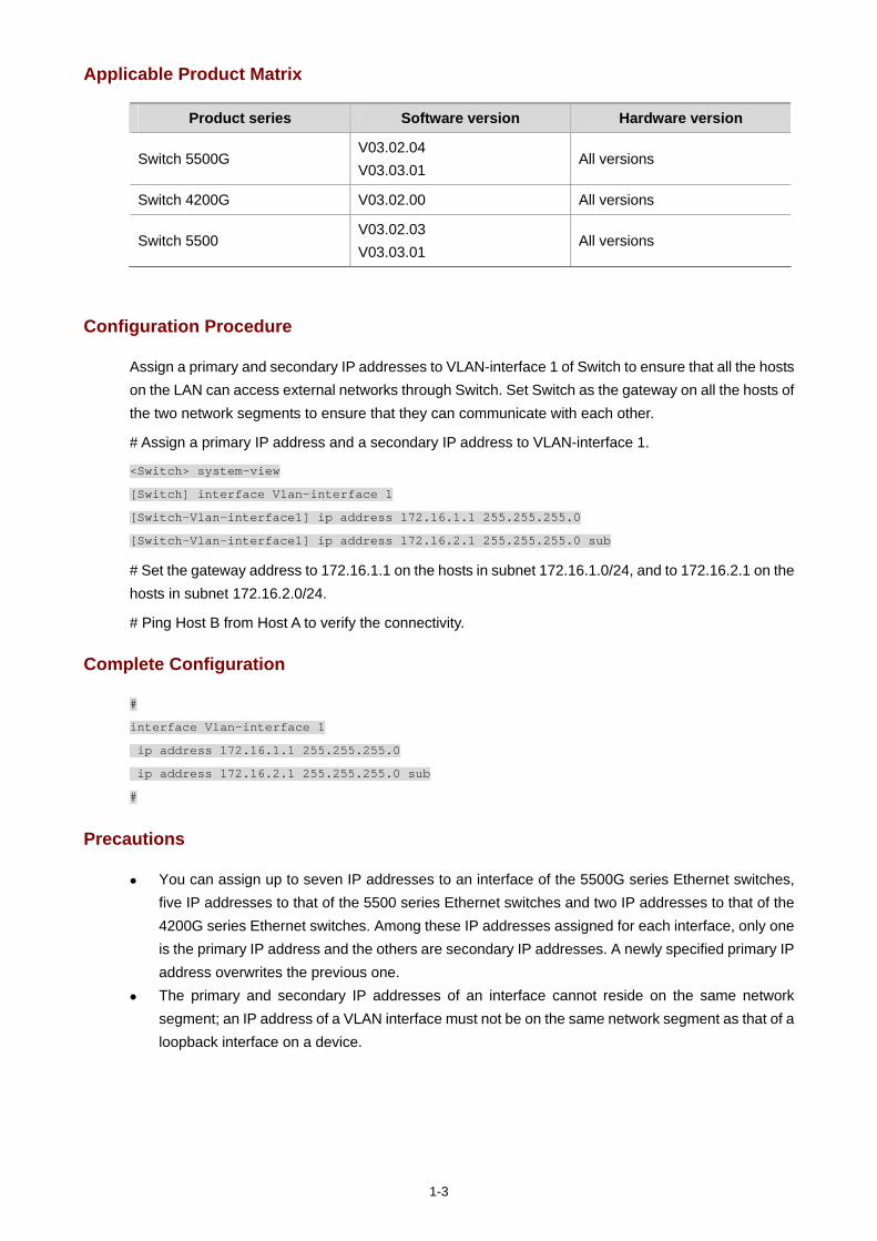
Configuration Procedure
Assign a primary and secondary IP addresses to VLAN-interface 1 of Switch to ensure that all the hosts on the LAN can access external networks through Switch. Set Switch as the gateway on all the hosts of the two network segments to ensure that they can communicate with each other.
# Assign a primary IP address and a secondary IP address to VLAN-interface 1.
<Switch> system-view
[Switch] interface Vlan-interface 1
[Switch-Vlan-interface1] ip address 172.16.1.1 255.255.255.0
[Switch-Vlan-interface1] ip address 172.16.2.1 255.255.255.0 sub
# Set the gateway address to 172.16.1.1 on the hosts in subnet 172.16.1.0/24, and to 172.16.2.1 on the hosts in subnet 172.16.2.0/24.
# Ping Host B from Host A to verify the connectivity.
Complete Configuration
#
interface Vlan-interface 1
ip address 172.16.1.1 255.255.255.0
ip address 172.16.2.1 255.255.255.0 sub
#
Precautions
You can assign up to seven IP addresses to an interface of the 5500G series Ethernet switches, five IP addresses to that of the 5500 series Ethernet switches and two IP addresses to that of the 4200G series Ethernet switches. Among these IP addresses assigned for each interface, only one is the primary IP address and the others are secondary IP addresses. A newly specified primary IP address overwrites the previous one.
The primary and secondary IP addresses of an interface cannot reside on the same network segment; an IP address of a VLAN interface must not be on the same network segment as that of a loopback interface on a device.

i
Table of Contents
1 Voice VLAN Configuration Guide ············································································································1-1 Configuring Voice VLAN ·························································································································1-1
Network Diagram·····························································································································1-1 Networking and Configuration Requirements··················································································1-1 Applicable Product Matrix················································································································1-2 Configuration Procedure··················································································································1-2 Complete Configuration···················································································································1-3 Precautions······································································································································1-4
1-1
1 Voice VLAN Configuration Guide
Configuring Voice VLAN
The voice VLAN feature improves voice traffic transmission priority and guarantee voice quality by assigning voice traffic to a dedicated VLAN for transmission. This dedicated VLAN is called the voice VLAN. A port is assigned to the voice VLAN in one of the following two modes:
In automatic mode, the switch checks the source MAC address of each incoming packet against the voice device OUI address list maintained on the switch. If a match is found, the switch assigns the port to the voice VLAN and tags the packet with the voice VLAN ID automatically. When the port joins the voice VLAN, a voice VLAN aging timer starts. If no voice packets have been received before the timer expires, the port leaves the voice VLAN.
In manual mode, you need to manually assign a port to or remove the port from the voice VLAN.
Network Diagram
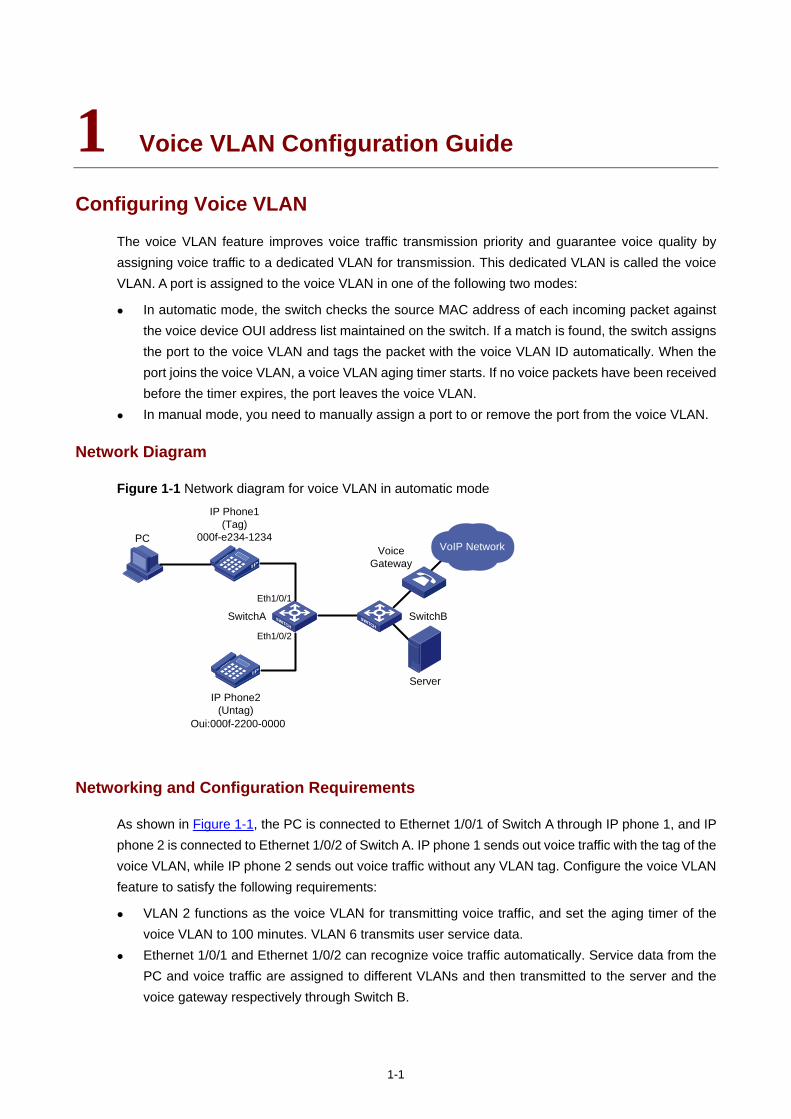
Figure 1-1 Network diagram for voice VLAN in automatic mode
VoIP NetworkPC
IP Phone1 (Tag)
000f-e234-1234
SwitchA SwitchB
Voice Gateway
ServerIP Phone2
(Untag)
Eth1/0/1
Eth1/0/2
Oui:000f-2200-0000
Networking and Configuration Requirements
As shown in Figure 1-1, the PC is connected to Ethernet 1/0/1 of Switch A through IP phone 1, and IP phone 2 is connected to Ethernet 1/0/2 of Switch A. IP phone 1 sends out voice traffic with the tag of the voice VLAN, while IP phone 2 sends out voice traffic without any VLAN tag. Configure the voice VLAN feature to satisfy the following requirements:
VLAN 2 functions as the voice VLAN for transmitting voice traffic, and set the aging timer of the voice VLAN to 100 minutes. VLAN 6 transmits user service data.
Ethernet 1/0/1 and Ethernet 1/0/2 can recognize voice traffic automatically. Service data from the PC and voice traffic are assigned to different VLANs and then transmitted to the server and the voice gateway respectively through Switch B.
1-2
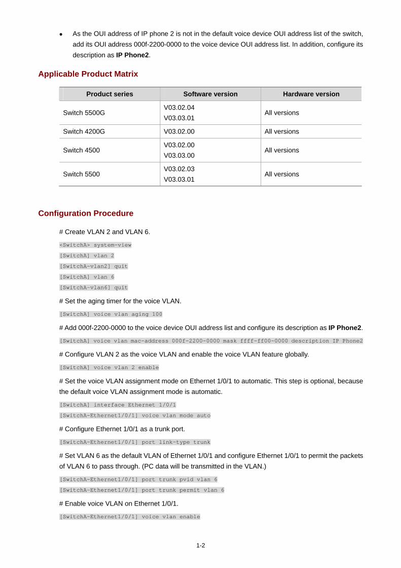
As the OUI address of IP phone 2 is not in the default voice device OUI address list of the switch, add its OUI address 000f-2200-0000 to the voice device OUI address list. In addition, configure its description as IP Phone2.
Applicable Product Matrix
Product series Software version Hardware version
Switch 5500G V03.02.04 V03.03.01
All versions
Switch 4200G V03.02.00 All versions
Switch 4500 V03.02.00 V03.03.00
All versions
Switch 5500 V03.02.03 V03.03.01
All versions
Configuration Procedure
# Create VLAN 2 and VLAN 6.
<SwitchA> system-view
[SwitchA] vlan 2
[SwitchA-vlan2] quit
[SwitchA] vlan 6
[SwitchA-vlan6] quit
# Set the aging timer for the voice VLAN.
[SwitchA] voice vlan aging 100
# Add 000f-2200-0000 to the voice device OUI address list and configure its description as IP Phone2.
[SwitchA] voice vlan mac-address 000f-2200-0000 mask ffff-ff00-0000 description IP Phone2
# Configure VLAN 2 as the voice VLAN and enable the voice VLAN feature globally.
[SwitchA] voice vlan 2 enable
# Set the voice VLAN assignment mode on Ethernet 1/0/1 to automatic. This step is optional, because the default voice VLAN assignment mode is automatic.
[SwitchA] interface Ethernet 1/0/1
[SwitchA-Ethernet1/0/1] voice vlan mode auto
# Configure Ethernet 1/0/1 as a trunk port.
[SwitchA-Ethernet1/0/1] port link-type trunk
# Set VLAN 6 as the default VLAN of Ethernet 1/0/1 and configure Ethernet 1/0/1 to permit the packets of VLAN 6 to pass through. (PC data will be transmitted in the VLAN.)
[SwitchA-Ethernet1/0/1] port trunk pvid vlan 6
[SwitchA-Ethernet1/0/1] port trunk permit vlan 6
# Enable voice VLAN on Ethernet 1/0/1.
[SwitchA-Ethernet1/0/1] voice vlan enable
1-3
After the configuration is finished, PC data is automatically assigned to the default VLAN of Ethernet 1/0/1 (namely the service VLAN) for transmission. When IP phone traffic arrives at Ethernet 1/0/1, the port automatically permits the voice VLAN and transmits the voice traffic with the voice VLAN tag, so that the IP phone can receive packets normally.
You can set Ethernet 1/0/1 as a hybrid or trunk port following the same procedure. In either case, you need to set the service VLAN as the default VLAN. As for voice traffic, when IP phone traffic arrives at the port, the port automatically permits the voice VLAN and transmits the traffic with the voice VLAN tag.
# Set the voice VLAN assignment mode of Ethernet 1/0/2 to manual. The mode must be manual because IP phone 2 can send out only untagged voice traffic.
[SwitchA-Ethernet1/0/1] quit
[SwitchA] interface Ethernet 1/0/2
[SwitchA-Ethernet1/0/2] undo voice vlan mode auto
# Configure Ethernet 1/0/2 to be an access port and permit the voice VLAN.
[SwitchA-Ethernet1/0/2] port access vlan 2
# Enable voice VLAN on Ethernet 1/0/2.
[SwitchA-Ethernet1/0/2] voice vlan enable
You can set Ethernet 1/0/2 as a trunk or hybrid port. In either case, configure the voice VLAN as the default VLAN and configure the port to remove the VLAN tag when forwarding traffic with the voice VLAN tag.
If traffic from IP phone 2 is tagged, configure Ethernet 1/0/2 as a trunk or hybrid port where the default VLAN cannot be set to VLAN 20 and the packets of VLAN 20 must be sent with the VLAN tag.
Complete Configuration
#
vlan 1 to 2
#
vlan 6
#
interface Ethernet1/0/1
port link-type trunk
port trunk permit vlan 1 6
port trunk pvid vlan 6
voice vlan enable
#
1-4
interface Ethernet1/0/2
port access vlan 2
undo voice vlan mode auto
voice vlan enable
#
voice vlan aging 100
voice vlan mac-address 000f-2200-0000 mask ffff-ff00-0000 description IP Phone2
voice vlan 2 enable
Precautions
Follow these guidelines when configuring the voice VLAN feature:
You cannot assign a port operating in automatic mode to the voice VLAN manually. Therefore, if you configure a VLAN as a voice VLAN and a protocol VLAN at the same time, you will be unable to associate the protocol VLAN with such a port. Refer to VLAN Configuration Guide in this manual for description on protocol VLAN.
You cannot set the voice VLAN as the default VLAN on a port operating in automatic voice VLAN assignment mode.
The switch supports only one voice VLAN. You cannot enable voice VLAN on a port configured with the Link Aggregation Control Protocol
(LACP). Only a static VLAN can be configured as the voice VLAN. When the number of ACL rules applied to a port reaches the upper threshold, enabling voice VLAN
on the port will fail. You can use the display voice vlan error-info command to locate such ports. In the voice VLAN operating in security mode, the device allows only the packets whose source
address matches a recognizable voice device vendor OUI to pass through. All other packets, including authentication packets such as 802.1x authentication packets, will be dropped. Therefore, you are recommended not to transmit both voice data and service data in the voice VLAN.

i
Table of Contents
1 GVRP Configuration Guide·······················································································································1-1 Configuring GVRP···································································································································1-1
Network Diagram·····························································································································1-1 Networking and Configuration Requirements··················································································1-1 Applicable Product Matrix················································································································1-1 Configuration Procedure··················································································································1-2 Complete Configuration···················································································································1-4 Precautions······································································································································1-6
1-1
1 GVRP Configuration Guide
Configuring GVRP
GVRP enables a switch to propagate local VLAN registration information to other participant switches and dynamically update the VLAN registration information from other switches to its local database about active VLAN members and through which port they can be reached. GVRP ensures that all switches on a bridged LAN maintain the same VLAN registration information, while less manual configuration workload is involved.
Network Diagram
Figure 1-1 Network diagram for GVRP configuration
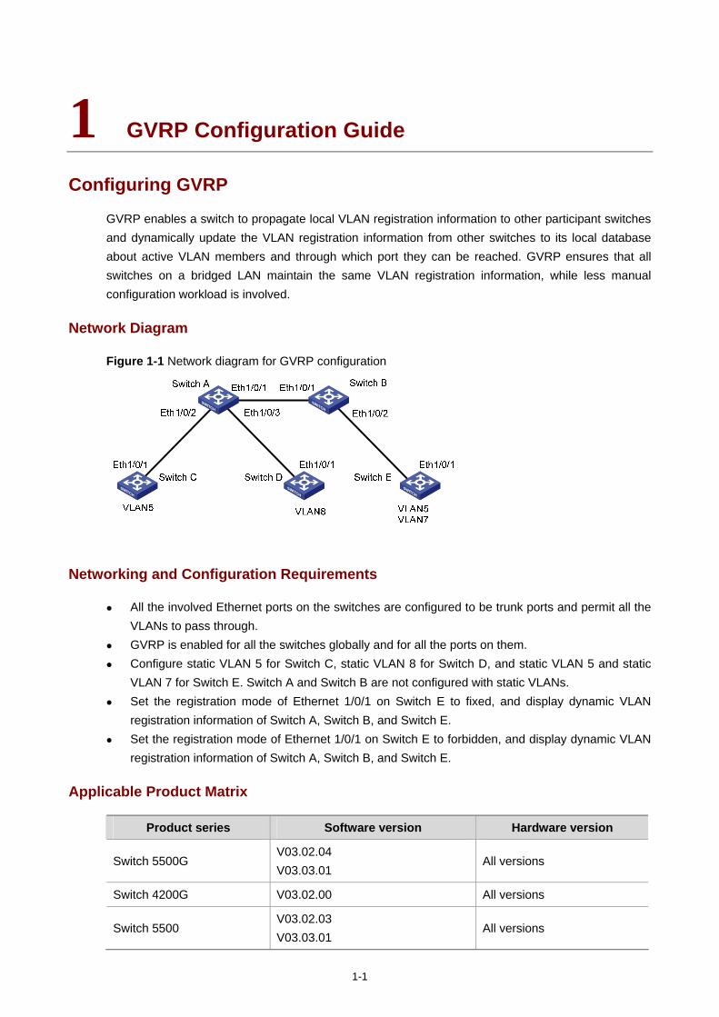
Networking and Configuration Requirements
All the involved Ethernet ports on the switches are configured to be trunk ports and permit all the VLANs to pass through.
GVRP is enabled for all the switches globally and for all the ports on them. Configure static VLAN 5 for Switch C, static VLAN 8 for Switch D, and static VLAN 5 and static
VLAN 7 for Switch E. Switch A and Switch B are not configured with static VLANs. Set the registration mode of Ethernet 1/0/1 on Switch E to fixed, and display dynamic VLAN
registration information of Switch A, Switch B, and Switch E. Set the registration mode of Ethernet 1/0/1 on Switch E to forbidden, and display dynamic VLAN
registration information of Switch A, Switch B, and Switch E.
Applicable Product Matrix
Product series Software version Hardware version
Switch 5500G V03.02.04 V03.03.01
All versions
Switch 4200G V03.02.00 All versions
Switch 5500 V03.02.03 V03.03.01
All versions
1-2
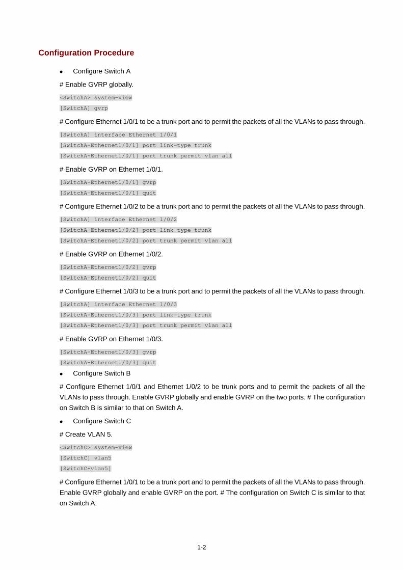
Configuration Procedure
Configure Switch A
# Enable GVRP globally.
<SwitchA> system-view
[SwitchA] gvrp
# Configure Ethernet 1/0/1 to be a trunk port and to permit the packets of all the VLANs to pass through.
[SwitchA] interface Ethernet 1/0/1
[SwitchA-Ethernet1/0/1] port link-type trunk
[SwitchA-Ethernet1/0/1] port trunk permit vlan all
# Enable GVRP on Ethernet 1/0/1.
[SwitchA-Ethernet1/0/1] gvrp
[SwitchA-Ethernet1/0/1] quit
# Configure Ethernet 1/0/2 to be a trunk port and to permit the packets of all the VLANs to pass through.
[SwitchA] interface Ethernet 1/0/2
[SwitchA-Ethernet1/0/2] port link-type trunk
[SwitchA-Ethernet1/0/2] port trunk permit vlan all
# Enable GVRP on Ethernet 1/0/2.
[SwitchA-Ethernet1/0/2] gvrp
[SwitchA-Ethernet1/0/2] quit
# Configure Ethernet 1/0/3 to be a trunk port and to permit the packets of all the VLANs to pass through.
[SwitchA] interface Ethernet 1/0/3
[SwitchA-Ethernet1/0/3] port link-type trunk
[SwitchA-Ethernet1/0/3] port trunk permit vlan all
# Enable GVRP on Ethernet 1/0/3.
[SwitchA-Ethernet1/0/3] gvrp
[SwitchA-Ethernet1/0/3] quit
Configure Switch B
# Configure Ethernet 1/0/1 and Ethernet 1/0/2 to be trunk ports and to permit the packets of all the VLANs to pass through. Enable GVRP globally and enable GVRP on the two ports. # The configuration on Switch B is similar to that on Switch A.
Configure Switch C
# Create VLAN 5.
<SwitchC> system-view
[SwitchC] vlan5
[SwitchC-vlan5]
# Configure Ethernet 1/0/1 to be a trunk port and to permit the packets of all the VLANs to pass through. Enable GVRP globally and enable GVRP on the port. # The configuration on Switch C is similar to that on Switch A.
1-3
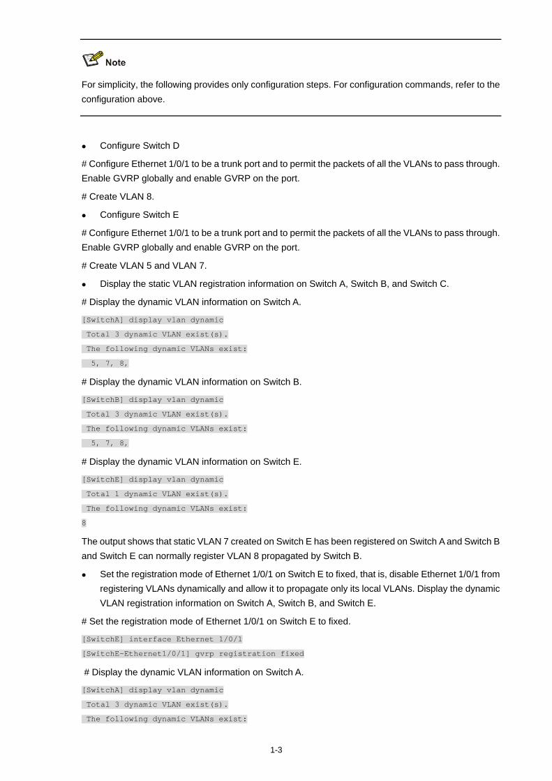
For simplicity, the following provides only configuration steps. For configuration commands, refer to the configuration above.
Configure Switch D
# Configure Ethernet 1/0/1 to be a trunk port and to permit the packets of all the VLANs to pass through. Enable GVRP globally and enable GVRP on the port.
# Create VLAN 8.
Configure Switch E
# Configure Ethernet 1/0/1 to be a trunk port and to permit the packets of all the VLANs to pass through. Enable GVRP globally and enable GVRP on the port.
# Create VLAN 5 and VLAN 7.
Display the static VLAN registration information on Switch A, Switch B, and Switch C.
# Display the dynamic VLAN information on Switch A.
[SwitchA] display vlan dynamic
Total 3 dynamic VLAN exist(s).
The following dynamic VLANs exist:
5, 7, 8,
# Display the dynamic VLAN information on Switch B.
[SwitchB] display vlan dynamic
Total 3 dynamic VLAN exist(s).
The following dynamic VLANs exist:
5, 7, 8,
# Display the dynamic VLAN information on Switch E.
[SwitchE] display vlan dynamic
Total 1 dynamic VLAN exist(s).
The following dynamic VLANs exist:
8
The output shows that static VLAN 7 created on Switch E has been registered on Switch A and Switch B and Switch E can normally register VLAN 8 propagated by Switch B.
Set the registration mode of Ethernet 1/0/1 on Switch E to fixed, that is, disable Ethernet 1/0/1 from registering VLANs dynamically and allow it to propagate only its local VLANs. Display the dynamic VLAN registration information on Switch A, Switch B, and Switch E.
# Set the registration mode of Ethernet 1/0/1 on Switch E to fixed.
[SwitchE] interface Ethernet 1/0/1
[SwitchE-Ethernet1/0/1] gvrp registration fixed
# Display the dynamic VLAN information on Switch A.
[SwitchA] display vlan dynamic
Total 3 dynamic VLAN exist(s).
The following dynamic VLANs exist:
1-4
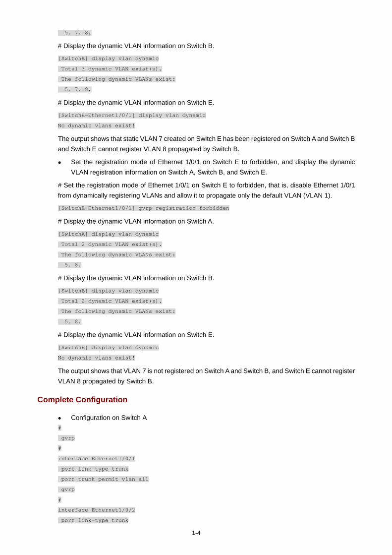
5, 7, 8,
# Display the dynamic VLAN information on Switch B.
[SwitchB] display vlan dynamic
Total 3 dynamic VLAN exist(s).
The following dynamic VLANs exist:
5, 7, 8,
# Display the dynamic VLAN information on Switch E.
[SwitchE-Ethernet1/0/1] display vlan dynamic
No dynamic vlans exist!
The output shows that static VLAN 7 created on Switch E has been registered on Switch A and Switch B and Switch E cannot register VLAN 8 propagated by Switch B.
Set the registration mode of Ethernet 1/0/1 on Switch E to forbidden, and display the dynamic VLAN registration information on Switch A, Switch B, and Switch E.
# Set the registration mode of Ethernet 1/0/1 on Switch E to forbidden, that is, disable Ethernet 1/0/1 from dynamically registering VLANs and allow it to propagate only the default VLAN (VLAN 1).
[SwitchE-Ethernet1/0/1] gvrp registration forbidden
# Display the dynamic VLAN information on Switch A.
[SwitchA] display vlan dynamic
Total 2 dynamic VLAN exist(s).
The following dynamic VLANs exist:
5, 8,
# Display the dynamic VLAN information on Switch B.
[SwitchB] display vlan dynamic
Total 2 dynamic VLAN exist(s).
The following dynamic VLANs exist:
5, 8,
# Display the dynamic VLAN information on Switch E.
[SwitchE] display vlan dynamic
No dynamic vlans exist!
The output shows that VLAN 7 is not registered on Switch A and Switch B, and Switch E cannot register VLAN 8 propagated by Switch B.
Complete Configuration
Configuration on Switch A #
gvrp
#
interface Ethernet1/0/1
port link-type trunk
port trunk permit vlan all
gvrp
#
interface Ethernet1/0/2
port link-type trunk
1-5
port trunk permit vlan all
gvrp
#
interface Ethernet1/0/3
port link-type trunk
port trunk permit vlan all
gvrp
Configuration on Switch B #
gvrp
#
interface Ethernet1/0/1
port link-type trunk
port trunk permit vlan all
gvrp
#
interface Ethernet1/0/2
port link-type trunk
port trunk permit vlan all
gvrp
Configuration on Switch C #
gvrp
#
vlan 5
#
interface Ethernet1/0/1
port link-type trunk
port trunk permit vlan all
gvrp
Configuration on Switch D #
gvrp
#
vlan 8
#
interface Ethernet1/0/1
port link-type trunk
port trunk permit vlan all
gvrp
Configuration on Switch E #
gvrp
#
vlan 5
#
vlan 7
#

1-6
interface Ethernet1/0/1
port link-type trunk
port trunk permit vlan all
gvrp registration forbidden
gvrp
Precautions
The port trunk permit vlan all command is designed for GVRP only. To prevent users of unauthorized VLANs from accessing restrictive resources from a port, do not use the command when GVRP is disabled on the port.
Before enabling GVRP on a port, enable GVRP globally first. Use GVRP only on trunk ports.

i
Table of Contents
1 Ethernet Interface Basic Configuration Guide ·······················································································1-1 Configuring the Basic Functions of an Ethernet Port··············································································1-1
Network Diagram·····························································································································1-1 Networking and Configuration Requirements··················································································1-1 Applicable Product Matrix················································································································1-1 Configuration Procedure··················································································································1-2 Complete Configuration···················································································································1-2 Precautions······································································································································1-2
1-1
1 Ethernet Interface Basic Configuration Guide
Configuring the Basic Functions of an Ethernet Port
An Ethernet port on an Ethernet switch can operate in one of the three link types:
Access: an access port can belong to only one VLAN and is generally used to connect to a PC. Trunk: a trunk port can belong to multiple VLANs. It can receive/send packets of multiple VLANs
and is generally used to connect to a switch. Hybrid: a hybrid port can belong to multiple VLANs. It can receive/send packets of multiple VLANs
and can be used to connect to either a switch or a PC.
You can add an Ethernet port to a specified VLAN. After that, the Ethernet port can forward the packets of the specified VLAN, so that the VLAN on this switch can intercommunicate with the same VLAN on the peer switch.
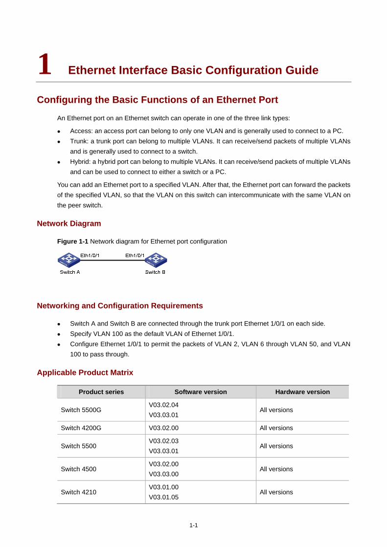
Network Diagram
Figure 1-1 Network diagram for Ethernet port configuration
Networking and Configuration Requirements
Switch A and Switch B are connected through the trunk port Ethernet 1/0/1 on each side. Specify VLAN 100 as the default VLAN of Ethernet 1/0/1. Configure Ethernet 1/0/1 to permit the packets of VLAN 2, VLAN 6 through VLAN 50, and VLAN
100 to pass through.
Applicable Product Matrix
Product series Software version Hardware version
Switch 5500G V03.02.04 V03.03.01
All versions
Switch 4200G V03.02.00 All versions
Switch 5500 V03.02.03 V03.03.01
All versions
Switch 4500 V03.02.00 V03.03.00
All versions
Switch 4210 V03.01.00 V03.01.05
All versions
1-2
Configuration Procedure
The following provides only the configuration on Switch A. The configuration on Switch B is similar to that on Switch A.
This configuration example assumes that VLAN 2, VLAN 6 through VLAN 50, and VLAN 100 have been created.
# Enter Ethernet port view of Ethernet 1/0/1.
<SwitchA> system-view
System View: return to User View with Ctrl+Z.
[SwitchA] interface ethernet1/0/1
# Configure Ethernet 1/0/1 as a trunk port.
[SwitchA-Ethernet1/0/1] port link-type trunk
# Configure Ethernet 1/0/1 to permit the packets of VLAN 1 through VLAN 3, VLAN 6 through VLAN 50, and VLAN 100 to pass through.
[SwitchA-Ethernet1/0/1] port trunk permit vlan 1 to 3 6 to 50 100
# Configure VLAN 100 as the default VLAN of Ethernet 1/0/1.
[SwitchA-Ethernet1/0/1] port trunk pvid vlan 100
Complete Configuration
#
interface Ethernet1/0/1
port link-type trunk
port trunk permit vlan 1 to 3 6 to 50 100
port trunk pvid vlan 100
#
Refer to VLAN Configuration Guide for the use of hybrid ports.
Precautions
Do not configure the port trunk permit vlan all command on a trunk port with GVRP disabled.

i
Table of Contents
1 Link Aggregation Configuration Guide ···································································································1-1 Configuring Link Aggregation··················································································································1-1
Network Diagram·····························································································································1-1 Networking and Configuration Requirements··················································································1-1 Applicable Product Matrix················································································································1-1 Configuration Procedure··················································································································1-2 Complete Configuration···················································································································1-3 Precautions······································································································································1-3
1-1
1 Link Aggregation Configuration Guide
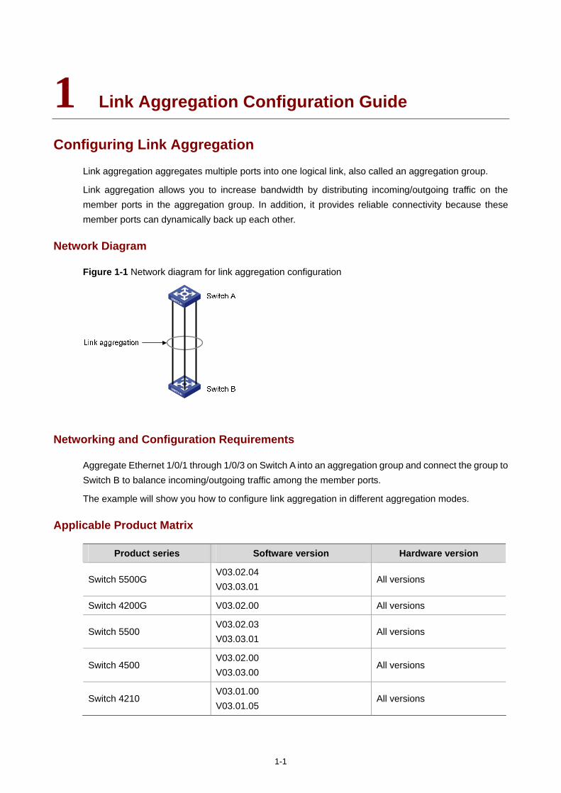
Configuring Link Aggregation
Link aggregation aggregates multiple ports into one logical link, also called an aggregation group.
Link aggregation allows you to increase bandwidth by distributing incoming/outgoing traffic on the member ports in the aggregation group. In addition, it provides reliable connectivity because these member ports can dynamically back up each other.
Network Diagram
Figure 1-1 Network diagram for link aggregation configuration
Networking and Configuration Requirements
Aggregate Ethernet 1/0/1 through 1/0/3 on Switch A into an aggregation group and connect the group to Switch B to balance incoming/outgoing traffic among the member ports.
The example will show you how to configure link aggregation in different aggregation modes.
Applicable Product Matrix
Product series Software version Hardware version
Switch 5500G V03.02.04 V03.03.01
All versions
Switch 4200G V03.02.00 All versions
Switch 5500 V03.02.03 V03.03.01
All versions
Switch 4500 V03.02.00 V03.03.00
All versions
Switch 4210 V03.01.00 V03.01.05
All versions
1-2
Configuration Procedure
The example only provides the configuration on Switch A. Perform the same configuration on Switch B to implement link aggregation.
1) In manual aggregation mode
# Create manual aggregation group 1.
<SwitchA> system-view
[SwitchA] link-aggregation group 1 mode manual
# Add Ethernet 1/0/1 through Ethernet 1/0/3 to aggregation group 1.
[SwitchA] interface Ethernet1/0/1
[SwitchA -Ethernet1/0/1] port link-aggregation group 1
[SwitchA -Ethernet1/0/1] quit
[SwitchA] interface Ethernet1/0/2
[SwitchA -Ethernet1/0/2] port link-aggregation group 1
[SwitchA -Ethernet1/0/2] quit
[SwitchA] interface Ethernet1/0/3
[SwitchA-Ethernet1/0/3] port link-aggregation group 1
2) In static LACP aggregation mode
# Create static aggregation group 1.
<SwitchA> system-view
[SwitchA] link-aggregation group 1 mode static
# Add Ethernet 1/0/1 through Ethernet 1/0/3 to aggregation group 1.
[SwitchA] interface Ethernet1/0/1
[SwitchA-Ethernet1/0/1] port link-aggregation group 1
[SwitchA-Ethernet1/0/1] quit
[SwitchA] interface Ethernet1/0/2
[SwitchA-Ethernet1/0/2] port link-aggregation group 1
[SwitchA-Ethernet1/0/2] quit
[SwitchA] interface Ethernet1/0/3
[SwitchA-Ethernet1/0/3] port link-aggregation group 1
3) In dynamic LACP aggregation mode
# Enable LACP on Ethernet 1/0/1 through Ethernet 1/0/3.
<SwitchA> system-view
[SwitchA] interface Ethernet1/0/1
[SwitchA-Ethernet1/0/1] lacp enable
[SwitchA-Ethernet1/0/1] quit
[SwitchA] interface Ethernet1/0/2
[SwitchA-Ethernet1/0/2] lacp enable
[SwitchA-Ethernet1/0/2] quit
[SwitchA] interface Ethernet1/0/3
1-3
[SwitchA-Ethernet1/0/3] lacp enable
Complete Configuration
1) In manual aggregation mode #
link-aggregation group 1 mode manual
#
interface Ethernet1/0/1
port link-aggregation group 1
#
interface Ethernet1/0/2
port link-aggregation group 1
#
interface Ethernet1/0/3
port link-aggregation group 1
#
2) In static LACP aggregation mode #
link-aggregation group 1 mode static
#
interface Ethernet1/0/1
port link-aggregation group 1
#
interface Ethernet1/0/2
port link-aggregation group 1
#
interface Ethernet1/0/3
port link-aggregation group 1
#
3) In dynamic LACP aggregation mode #
interface Ethernet1/0/1
lacp enable
#
interface Ethernet1/0/2
lacp enable
#
interface Ethernet1/0/3
lacp enable
#
Precautions
If static LACP aggregation or manual aggregation is adopted, you are recommended not to cross-connect the aggregation member ports at the two ends to avoid packet loss. For example, if local port 1 is connected to remote port 2, do not connect local port 2 to remote port 1.
Dynamic LACP aggregation mode is not recommended in actual networking scenarios.

1-4
The implementation of static aggregation varies by platform software version. This may result in problems when products using different platform software versions are interconnected through static aggregation groups. Use the display version command to view the platform software version.
The 4210 switch only supports manually-configured aggregation groups.

i
Table of Contents
1 Port Isolation Configuration Guide··········································································································1-1 Configuring Port Isolation························································································································1-1
Network Diagram·····························································································································1-1 Networking and Configuration Requirements··················································································1-1 Applicable Product Matrix················································································································1-1 Configuration Procedure··················································································································1-2 Complete Configuration···················································································································1-2 Precautions······································································································································1-2
1-1
1 Port Isolation Configuration Guide
Configuring Port Isolation
Port isolation allows you to add a port into an isolation group to isolate Layer-2 and Layer-3 traffic of the port from that of all other ports in the isolation group. While increasing network security, this allows for great flexibility.
Currently, an switch supports only one isolation group; however, the number of Ethernet ports in the isolation group is not limited.
Network Diagram
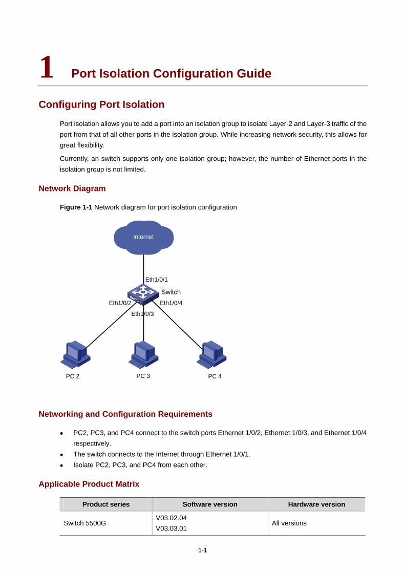
Figure 1-1 Network diagram for port isolation configuration
Internet
PC 2
Eth1/0/1
Switch
Eth1/0/3
Eth1/0/4
PC 3 PC 4
Eth1/0/2
Networking and Configuration Requirements
PC2, PC3, and PC4 connect to the switch ports Ethernet 1/0/2, Ethernet 1/0/3, and Ethernet 1/0/4 respectively.
The switch connects to the Internet through Ethernet 1/0/1. Isolate PC2, PC3, and PC4 from each other.
Applicable Product Matrix
Product series Software version Hardware version
Switch 5500G V03.02.04 V03.03.01
All versions
1-2
Product series Software version Hardware version
Switch 4200G V03.02.00 All versions
Switch 4500 V03.02.00 V03.03.00
All versions
Switch 5500 V03.02.03 V03.03.01
All versions
Switch 4210 V03.01.00 V03.01.05
All versions
Configuration Procedure
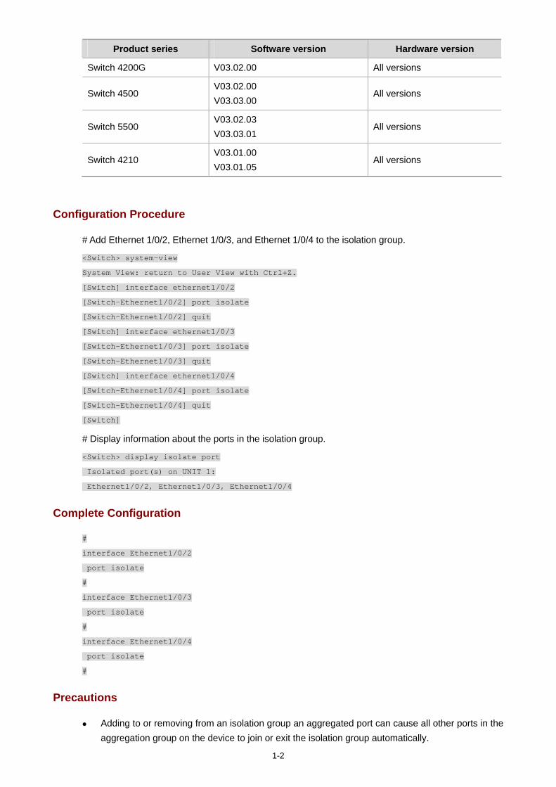
# Add Ethernet 1/0/2, Ethernet 1/0/3, and Ethernet 1/0/4 to the isolation group.
<Switch> system-view
System View: return to User View with Ctrl+Z.
[Switch] interface ethernet1/0/2
[Switch-Ethernet1/0/2] port isolate
[Switch-Ethernet1/0/2] quit
[Switch] interface ethernet1/0/3
[Switch-Ethernet1/0/3] port isolate
[Switch-Ethernet1/0/3] quit
[Switch] interface ethernet1/0/4
[Switch-Ethernet1/0/4] port isolate
[Switch-Ethernet1/0/4] quit
[Switch]
# Display information about the ports in the isolation group.
<Switch> display isolate port
Isolated port(s) on UNIT 1:
Ethernet1/0/2, Ethernet1/0/3, Ethernet1/0/4
Complete Configuration
#
interface Ethernet1/0/2
port isolate
#
interface Ethernet1/0/3
port isolate
#
interface Ethernet1/0/4
port isolate
#
Precautions
Adding to or removing from an isolation group an aggregated port can cause all other ports in the aggregation group on the device to join or exit the isolation group automatically.

1-3
After an aggregated port is removed from its aggregation group, all other member ports will still stay in the isolation group that they have joined (if any).
Removing an aggregation group does not remove its member ports from the isolation group that they have joined (if any).
Adding an isolated port to an aggregation group can cause all the member ports in the aggregation group to join the isolation group automatically.
Cross-device port isolation is supported on the Switch 5500/ Switch 4500 switches in an XRN fabric. This allows ports on different units to join the same isolation group.
For Switch 5500/ Switch 4500 switches in an XRN fabric, adding a member port in a cross-device aggregation group to an isolation group does not cause other member ports to join the isolation group automatically.
i
Table of Contents
1 Port Security Configuration Guide ··········································································································1-1 Configuring Port Security autolearn Mode······························································································1-1
Network Diagram·····························································································································1-1 Networking and Configuration Requirements··················································································1-1 Applicable Product Matrix················································································································1-1 Configuration Procedure··················································································································1-2 Complete Configuration···················································································································1-2 Precautions······································································································································1-2
Configuring Port Security mac-authentication Mode ··············································································1-2 Network Diagram·····························································································································1-3 Networking and Configuration Requirements··················································································1-3 Applicable Product Matrix················································································································1-3 Configuration Procedure··················································································································1-4 Complete Configuration···················································································································1-5 Precautions······································································································································1-5
Configuring Port Security userlogin-withoui Mode··················································································1-5 Network Diagram·····························································································································1-6 Networking and Configuration Requirements··················································································1-6 Applicable Product Matrix················································································································1-6 Configuration Procedure··················································································································1-7 Complete Configuration···················································································································1-8 Precautions······································································································································1-9
Configuring Port Security mac-else-userlogin-secure-ext Mode ····························································1-9 Network Diagram·····························································································································1-9 Networking and Configuration Requirements··················································································1-9 Applicable Product Matrix··············································································································1-10 Configuration Procedure················································································································1-10 Complete Configuration·················································································································1-11 Precautions····································································································································1-12
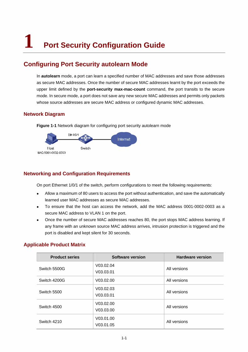
1-1
1 Port Security Configuration Guide
Configuring Port Security autolearn Mode
In autolearn mode, a port can learn a specified number of MAC addresses and save those addresses as secure MAC addresses. Once the number of secure MAC addresses learnt by the port exceeds the upper limit defined by the port-security max-mac-count command, the port transits to the secure mode. In secure mode, a port does not save any new secure MAC addresses and permits only packets whose source addresses are secure MAC address or configured dynamic MAC addresses.
Network Diagram
Figure 1-1 Network diagram for configuring port security autolearn mode
Networking and Configuration Requirements
On port Ethernet 1/0/1 of the switch, perform configurations to meet the following requirements:
Allow a maximum of 80 users to access the port without authentication, and save the automatically learned user MAC addresses as secure MAC addresses.
To ensure that the host can access the network, add the MAC address 0001-0002-0003 as a secure MAC address to VLAN 1 on the port.
Once the number of secure MAC addresses reaches 80, the port stops MAC address learning. If any frame with an unknown source MAC address arrives, intrusion protection is triggered and the port is disabled and kept silent for 30 seconds.
Applicable Product Matrix
Product series Software version Hardware version
Switch 5500G V03.02.04 V03.03.01
All versions
Switch 4200G V03.02.00 All versions
Switch 5500 V03.02.03 V03.03.01
All versions
Switch 4500 V03.02.00 V03.03.00
All versions
Switch 4210 V03.01.00 V03.01.05
All versions
1-2
Configuration Procedure
# Enter system view.
<Switch> system-view
# Enable port security.
[Switch] port-security enable
# Enter Ethernet 1/0/1 port view.
[Switch] interface Ethernet1/0/1
# Set the maximum number of MAC addresses allowed on the port to 80.
[Switch-Ethernet1/0/1] port-security max-mac-count 80
# Set the port security mode to autolearn.
[Switch-Ethernet1/0/1] port-security port-mode autolearn
# Add the MAC address 0001-0002-0003 as a secure MAC address to VLAN 1.
[Switch-Ethernet1/0/1] mac-address security 0001-0002-0003 vlan 1
# Configure the port to be silent for 30 seconds after intrusion protection is triggered.
[Switch-Ethernet1/0/1] port-security intrusion-mode disableport-temporarily
[Switch-Ethernet1/0/1] quit
[Switch] port-security timer disableport 30
Complete Configuration
#
port-security enable
port-security timer disableport 30
#
interface Ethernet1/0/1
port-security max-mac-count 80
port-security port-mode autolearn
port-security intrusion-mode disableport-temporarily
mac-address security 0001-0002-0003 vlan 1
#
Precautions
Before enabling port security, be sure to disable 802.1x and MAC authentication globally. On a port configured with port security, you cannot configure the maximum number of MAC
addresses that the port can learn, reflector port for port mirroring, fabric port or link aggregation.
Configuring Port Security mac-authentication Mode
In mac-authentication mode, a port performs MAC authentication of users.

1-3
Network Diagram
Figure 1-2 Network diagram for configuring port security mac-authentication mode
Networking and Configuration Requirements
The host connects to the switch through the port Ethernet 1/0/1, and the switch authenticates the host through the RADIUS server. If the authentication is successful, the host is authorized to access the Internet.
On port Ethernet 1/0/1 of the switch, perform configurations to meet the following requirements:
The switch performs MAC authentication of users. All users belong to the domain aabbcc.net, and each of them uses the MAC address as username
and password for authentication. Whenever a packet fails MAC authentication, intrusion protection is triggered to filter packets
whose source MAC addresses are the same as that of the packet failing the authentication, ensuring the security of the port.
Applicable Product Matrix
Product series Software version Hardware version
Switch 5500G V03.02.04 V03.03.01
All versions
Switch 4200G V03.02.00 All versions
Switch 5500 V03.02.03 V03.03.01
All versions
Switch 4500 V03.02.00 V03.03.00
All versions
Switch 4210 V03.01.00 V03.01.05
All versions
1-4
Configuration Procedure
The following configurations involve some AAA/RADIUS configuration commands. For details about the commands, refer to AAA Operation.
Configurations on the user host and the RADIUS server are omitted.
Configure RADIUS parameters
# Create a RADIUS scheme named radius1.
<Switch> system-view
[Switch] radius scheme radius1
# Specify the primary RADIUS authentication server and primary RADIUS accounting server.
[Switch-radius-radius1] primary authentication 192.168.1.3
[Switch-radius-radius1] primary accounting 192.168.1.2
# Specify the secondary RADIUS authentication server and secondary RADIUS accounting server.
[Switch-radius-radius1] secondary authentication 192.168.1.2
[Switch-radius-radius1] secondary accounting 192.168.1.3
# Set the shared key for message exchange between the switch and the RADIUS authentication servers to name.
[Switch-radius-radius1] key authentication name
# Set the shared key for message exchange between the switch and the accounting RADIUS servers to name.
[Switch-radius-radius1] key accounting name
# Configure the switch to send a username without the domain name to the RADIUS server.
[Switch-radius-radius1] user-name-format without-domain
[Switch-radius-radius1] quit
# Create a domain named aabbcc.net and enter its view.
[Switch] domain aabbcc.net
# Specify the RADIUS scheme for the domain.
[Switch-isp-aabbcc.net] scheme radius-scheme radius1
[Switch-isp-aabbcc.net] quit
# Set aabbcc.net as the default user domain.
[Switch] domain default enable aabbcc.net
# Configure the switch to use MAC addresses as usernames for authentication, specifying that the MAC addresses should be lowercase without separators.
[Switch] mac-authentication authmode usernameasmacaddress usernameformat without-hyphen
# Specify the ISP domain for MAC authentication.
[Switch] mac-authentication domain aabbcc.net
# Enable port security.
1-5
[Switch] port-security enable
# Set the port security mode to mac-authentication.
[Switch] interface Ethernet 1/0/1
[Switch-Ethernet1/0/1] port-security port-mode mac-authentication
# Configure the port to drop packets whose source addresses are the same as that of the packet failing MAC authentication after intrusion protection is triggered.
[Switch-Ethernet1/0/1] port-security intrusion-mode blockmac
Complete Configuration
#
domain default enable aabbcc.net
#
port-security enable
#
MAC-authentication domain aabbcc.net
#
radius scheme radius1
server-type standard
primary authentication 192.168.1.3
primary accounting 192.168.1.2
secondary authentication 192.168.1.2
secondary accounting 192.168.1.3
key authentication name
key accounting name
user-name-format without-domain
#
domain aabbcc.net
scheme radius-scheme radius1
#
interface Ethernet1/0/1
port-security port-mode mac-authentication
port-security intrusion-mode blockmac
Precautions
Before enabling port security, be sure to disable 802.1x and MAC authentication globally. On a port configured with port security, you cannot configure the maximum number of MAC
addresses that the port can learn, reflector port for port mirroring, fabric port, or link aggregation.
Configuring Port Security userlogin-withoui Mode
In the userlogin-withoui mode, a port authenticates users using MAC-based 802.1x and permits only packets from authenticated users. Besides, the port also allows packets whose source MAC addresses have a specified organizationally unique identifier (OUI) value to pass the port.
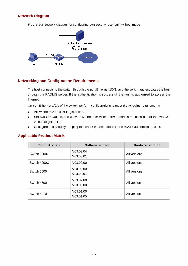
1-6
Network Diagram
Figure 1-3 Network diagram for configuring port security userlogin-withoui mode
Networking and Configuration Requirements
The host connects to the switch through the port Ethernet 1/0/1, and the switch authenticates the host through the RADIUS server. If the authentication is successful, the host is authorized to access the Internet.
On port Ethernet 1/0/1 of the switch, perform configurations to meet the following requirements:
Allow one 802.1x user to get online. Set two OUI values, and allow only one user whose MAC address matches one of the two OUI
values to get online. Configure port security trapping to monitor the operations of the 802.1x-authenticated user.
Applicable Product Matrix
Product series Software version Hardware version
Switch 5500G V03.02.04 V03.03.01
All versions
Switch 4200G V03.02.00 All versions
Switch 5500 V03.02.03 V03.03.01
All versions
Switch 4500 V03.02.00 V03.03.00
All versions
Switch 4210 V03.01.00 V03.01.05
All versions
1-7
Configuration Procedure
The following configurations involve some AAA/RADIUS configuration commands. For details about the commands, refer to AAA Operation.
Configurations on the user host and the RADIUS server are omitted.
Configure RADIUS parameters
# Create a RADIUS scheme named radius1.
<Switch> system-view
[Switch] radius scheme radius1
# Specify the primary RADIUS authentication server and primary RADIUS accounting server.
[Switch-radius-radius1] primary authentication 192.168.1.3
[Switch-radius-radius1] primary accounting 192.168.1.2
# Specify the secondary RADIUS authentication server and secondary RADIUS accounting server.
[Switch-radius-radius1] secondary authentication 192.168.1.2
[Switch-radius-radius1] secondary accounting 192.168.1.3
# Set the shared key for message exchange between the switch and the RADIUS authentication servers to name.
[Switch-radius-radius1] key authentication name
# Set the shared key for message exchange between the switch and the accounting RADIUS servers to name.
[Switch-radius-radius1] key accounting name
# Set the interval and the number of packet transmission attempts for the switch to send packets to the RADIUS server.
[Switch-radius-radius1] timer 5
[Switch-radius-radius1] retry 5
# Set the timer for the switch to send real-time accounting packets to the RADIUS server to 15 minutes.
[Switch-radius-radius1] timer realtime-accounting 15
# Configure the switch to send a username without the domain name to the RADIUS server.
[Switch-radius-radius1] user-name-format without-domain
[Switch-radius-radius1] quit
# Create a domain named aabbcc.net and enter its view.
[Switch] domain aabbcc.net
# Specify radius1 as the RADIUS scheme of the user domain, and the local authentication scheme as the backup scheme when the RADIUS server is not available.
[Switch-isp-aabbcc.net] scheme radius-scheme radius1 local
# Set the maximum number of users of the ISP domain to 30.
[Switch-isp-aabbcc.net] access-limit enable 30
1-8
# Enable the idle disconnecting function and set the related parameters.
[Switch-isp-aabbcc.net] idle-cut enable 20 2000
[Switch-isp-aabbcc.net] quit
# Set aabbcc.net as the default user domain.
[Switch] domain default enable aabbcc.net
# Create a local user.
[Switch] local-user localuser
[Switch-luser-localuser] service-type lan-access
[Switch-luser-localuser] password simple localpass
Configure port security
# Enable port security.
[Switch] port-security enable
# Add two OUI values.
[Switch] port-security oui 1234-0100-1111 index 1
[Switch] port-security oui 1234-0200-1111 index 2
# Set the port security mode to userlogin-withoui.
[Switch] interface Ethernet 1/0/1
[Switch-Ethernet1/0/1] port-security port-mode userlogin-withoui
[Switch-Ethernet1/0/1] quit
# Configure port security trapping.
[Switch] port-security trap dot1xlogfailure
[Switch] port-security trap dot1xlogon
[Switch] port-security trap dot1xlogoff
Complete Configuration
#
domain default enable aabbcc.net
#
port-security enable
port-security trap dot1xlogon
port-security trap dot1xlogoff
port-security trap dot1xlogfailure
port-security oui 1234-0100-0000 index 1
port-security oui 1234-0200-0000 index 2
#
radius scheme radius1
server-type standard
primary authentication 192.168.1.3
primary accounting 192.168.1.2
secondary authentication 192.168.1.2
secondary accounting 192.168.1.3
key authentication name
key accounting name
timer realtime-accounting 15
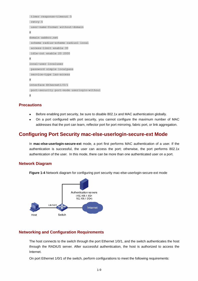
1-9
timer response-timeout 5
retry 5
user-name-format without-domain
#
domain aabbcc.net
scheme radius-scheme radius1 local
access-limit enable 30
idle-cut enable 20 2000
#
local-user localuser
password simple localpass
service-type lan-access
#
interface Ethernet1/0/1
port-security port-mode userlogin-withoui
#
Precautions
Before enabling port security, be sure to disable 802.1x and MAC authentication globally. On a port configured with port security, you cannot configure the maximum number of MAC
addresses that the port can learn, reflector port for port mirroring, fabric port, or link aggregation.
Configuring Port Security mac-else-userlogin-secure-ext Mode
In mac-else-userlogin-secure-ext mode, a port first performs MAC authentication of a user. If the authentication is successful, the user can access the port; otherwise, the port performs 802.1x authentication of the user. In this mode, there can be more than one authenticated user on a port.
Network Diagram
Figure 1-4 Network diagram for configuring port security mac-else-userlogin-secure-ext mode
Networking and Configuration Requirements
The host connects to the switch through the port Ethernet 1/0/1, and the switch authenticates the host through the RADIUS server. After successful authentication, the host is authorized to access the Internet.
On port Ethernet 1/0/1 of the switch, perform configurations to meet the following requirements:
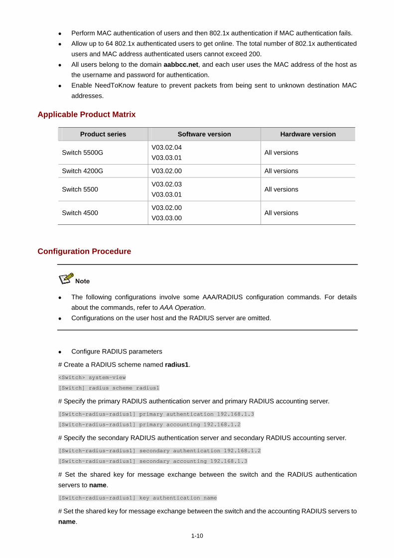
1-10
Perform MAC authentication of users and then 802.1x authentication if MAC authentication fails. Allow up to 64 802.1x authenticated users to get online. The total number of 802.1x authenticated
users and MAC address authenticated users cannot exceed 200. All users belong to the domain aabbcc.net, and each user uses the MAC address of the host as
the username and password for authentication. Enable NeedToKnow feature to prevent packets from being sent to unknown destination MAC
addresses.
Applicable Product Matrix
Product series Software version Hardware version
Switch 5500G V03.02.04 V03.03.01
All versions
Switch 4200G V03.02.00 All versions
Switch 5500 V03.02.03 V03.03.01
All versions
Switch 4500 V03.02.00 V03.03.00
All versions
Configuration Procedure
The following configurations involve some AAA/RADIUS configuration commands. For details about the commands, refer to AAA Operation.
Configurations on the user host and the RADIUS server are omitted.
Configure RADIUS parameters
# Create a RADIUS scheme named radius1.
<Switch> system-view
[Switch] radius scheme radius1
# Specify the primary RADIUS authentication server and primary RADIUS accounting server.
[Switch-radius-radius1] primary authentication 192.168.1.3
[Switch-radius-radius1] primary accounting 192.168.1.2
# Specify the secondary RADIUS authentication server and secondary RADIUS accounting server.
[Switch-radius-radius1] secondary authentication 192.168.1.2
[Switch-radius-radius1] secondary accounting 192.168.1.3
# Set the shared key for message exchange between the switch and the RADIUS authentication servers to name.
[Switch-radius-radius1] key authentication name
# Set the shared key for message exchange between the switch and the accounting RADIUS servers to name.
1-11
[Switch-radius-radius1] key accounting name
# Set the interval and the number of packet transmission attempts for the switch to send packets to the RADIUS server.
[Switch-radius-radius1] timer 5
[Switch-radius-radius1] retry 5
# Set the timer for the switch to send real-time accounting packets to the RADIUS server to 15 minutes.
[Switch-radius-radius1] timer realtime-accounting 15
# Configure the switch to send a username without the domain name to the RADIUS server.
[Switch-radius-radius1] user-name-format without-domain
[Switch-radius-radius1] quit
# Create a domain named aabbcc.net and enter its view.
[Switch] domain aabbcc.net
# Specify the RADIUS scheme for the domain.
[Switch-isp-aabbcc.net] scheme radius-scheme radius1
# Enable the idle disconnecting function and set the related parameters.
[Switch-isp-aabbcc.net] idle-cut enable 20 2000
[Switch-isp-aabbcc.net] quit
# Set aabbcc.net as the default user domain.
[Switch] domain default enable aabbcc.net
# Set the maximum number of concurrent 802.1x users.
[Switch] dot1x max-user 64
# Configure the switch to use MAC addresses as usernames for authentication, specifying that the MAC addresses should be lowercase without separators.
[Switch] mac-authentication authmode usernameasmacaddress usernameformat without-hyphen
# Specify the ISP domain for MAC authentication.
[Switch] mac-authentication domain aabbcc.net
# Enable port security.
[Switch] port-security enable
# Set the maximum number of secure MAC addresses allowed on the port to 200.
[Switch] interface Ethernet 1/0/1
[Switch-Ethernet1/0/1] port-security max-mac-count 200
# Set the port security mode to mac-else-userlogin-secure-ext.
[Switch-Ethernet1/0/1] port-security port-mode mac-else-userlogin-secure-ext
# Set the NeedToKnow mode of the port to ntkonly.
[Switch-Ethernet1/0/1] port-security ntk-mode ntkonly
Complete Configuration
#
domain default enable aabbcc.net
#
1-12
port-security enable
#
MAC-authentication domain aabbcc.net
#
radius scheme radius1
server-type standard
primary authentication 192.168.1.3
primary accounting 192.168.1.2
secondary authentication 192.168.1.2
secondary accounting 192.168.1.3
key authentication name
key accounting name
timer realtime-accounting 15
timer response-timeout 5
retry 5
user-name-format without-domain
#
domain aabbcc.net
scheme radius-scheme radius1
idle-cut enable 20 2000
#
interface Ethernet1/0/1
port-security max-mac-count 200
port-security port-mode mac-else-userlogin-secure-ext
port-security ntk-mode ntkonly
dot1x max-user 64
Precautions
Before enabling port security, be sure to disable 802.1x and MAC authentication globally. On a port configured with port security, you cannot configure the maximum number of MAC
addresses that the port can learn, reflector port for port mirroring, fabric port, or link aggregation.

i
Table of Contents
1 Port Binding Configuration Guide ···········································································································1-1 Configuring a Port Binding ······················································································································1-1
Network Diagram·····························································································································1-1 Networking and Configuration Requirements··················································································1-1 Applicable Product Matrix················································································································1-1 Configuration Procedure··················································································································1-2 Complete Configuration···················································································································1-2
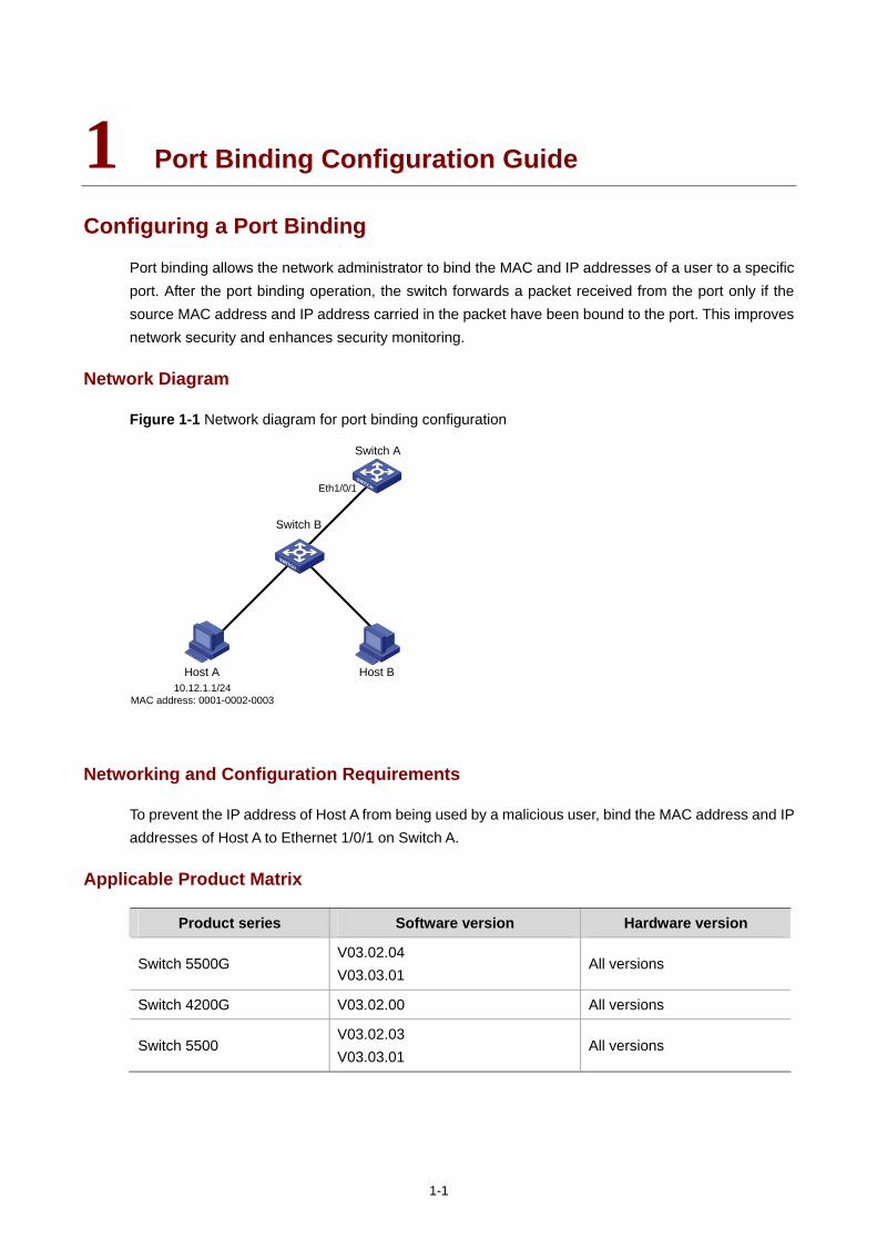
1-1
1 Port Binding Configuration Guide
Configuring a Port Binding
Port binding allows the network administrator to bind the MAC and IP addresses of a user to a specific port. After the port binding operation, the switch forwards a packet received from the port only if the source MAC address and IP address carried in the packet have been bound to the port. This improves network security and enhances security monitoring.
Network Diagram
Figure 1-1 Network diagram for port binding configuration
10.12.1.1/24MAC address: 0001-0002-0003
Host A Host B
Eth1/0/1
Switch A
Switch B
Networking and Configuration Requirements
To prevent the IP address of Host A from being used by a malicious user, bind the MAC address and IP addresses of Host A to Ethernet 1/0/1 on Switch A.
Applicable Product Matrix
Product series Software version Hardware version
Switch 5500G V03.02.04 V03.03.01
All versions
Switch 4200G V03.02.00 All versions
Switch 5500 V03.02.03 V03.03.01
All versions
1-2
Configuration Procedure
# Enter system view.
<SwitchA> system-view
# Enter Ethernet 1/0/1 port view.
[SwitchA] interface Ethernet1/0/1
# Bind the MAC address and the IP address of Host 1 to Ethernet 1/0/1.
[SwitchA-Ethernet1/0/1] am user-bind mac-addr 0001-0002-0003 ip-addr 10.12.1.1
Complete Configuration
#
interface Ethernet1/0/1
am user-bind mac-addr 0001-0002-0003 ip-addr 10.12.1.1
#

i
Table of Contents
1 MAC Address Table Management Configuration Guide········································································1-1 MAC Address Table Management··········································································································1-1
Network Diagram·····························································································································1-1 Networking and Configuration Requirements··················································································1-1 Applicable Product Matrix················································································································1-1 Configuration Procedure··················································································································1-2 Complete Configuration···················································································································1-2 Precautions······································································································································1-3
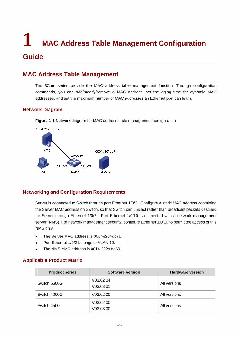
1-1
1 MAC Address Table Management Configuration
Guide
MAC Address Table Management
The 3Com series provide the MAC address table management function. Through configuration commands, you can add/modify/remove a MAC address, set the aging time for dynamic MAC addresses, and set the maximum number of MAC addresses an Ethernet port can learn.
Network Diagram
Figure 1-1 Network diagram for MAC address table management configuration
Networking and Configuration Requirements
Server is connected to Switch through port Ethernet 1/0/2. Configure a static MAC address containing the Server MAC address on Switch, so that Switch can unicast rather than broadcast packets destined for Server through Ethernet 1/0/2. Port Ethernet 1/0/10 is connected with a network management server (NMS). For network management security, configure Ethernet 1/0/10 to permit the access of this NMS only.
The Server MAC address is 000f-e20f-dc71. Port Ethernet 1/0/2 belongs to VLAN 10. The NMS MAC address is 0014-222c-aa69.
Applicable Product Matrix
Product series Software version Hardware version
Switch 5500G V03.02.04 V03.03.01
All versions
Switch 4200G V03.02.00 All versions
Switch 4500 V03.02.00 V03.03.00
All versions
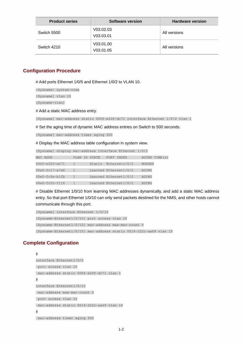
1-2
Product series Software version Hardware version
Switch 5500 V03.02.03 V03.03.01
All versions
Switch 4210 V03.01.00 V03.01.05
All versions
Configuration Procedure
# Add ports Ethernet 1/0/5 and Ethernet 1/0/2 to VLAN 10.
<Sysname> system-view
[Sysname] vlan 10
[Sysname-vlan]
# Add a static MAC address entry.
[Sysname] mac-address static 000f-e20f-dc71 interface Ethernet 1/0/2 vlan 1
# Set the aging time of dynamic MAC address entries on Switch to 500 seconds.
[Sysname] mac-address timer aging 500
# Display the MAC address table configuration in system view.
[Sysname] display mac-address interface Ethernet 1/0/2
MAC ADDR VLAN ID STATE PORT INDEX AGING TIME(s)
000f-e20f-dc71 1 Static Ethernet1/0/2 NOAGED
00e0-fc17-a7d6 1 Learned Ethernet1/0/2 AGING
00e0-fc5e-b1fb 1 Learned Ethernet1/0/2 AGING
00e0-fc55-f116 1 Learned Ethernet1/0/2 AGING
# Disable Ethernet 1/0/10 from learning MAC addresses dynamically, and add a static MAC address entry. So that port Ethernet 1/0/10 can only send packets destined for the NMS, and other hosts cannot communicate through this port.
[Sysname] interface Ethernet 1/0/10
[Sysname-Ethernet1/0/10] port access vlan 10
[Sysname-Ethernet1/0/10] mac-address max-mac-count 0
[Sysname-Ethernet1/0/10] mac-address static 0014-222c-aa69 vlan 10
Complete Configuration
#
interface Ethernet1/0/2
port access vlan 10
mac-address static 000f-e20f-dc71 vlan 1
#
interface Ethernet1/0/10
mac-address max-mac-count 0
port access vlan 10
mac-address static 0014-222c-aa69 vlan 10
#
mac-address timer aging 500

1-3
Precautions
When you add a MAC address entry, the port specified by the interface keyword must belong to the VLAN specified by the vlan keyword in the command. Otherwise, the entry will not be added.
If the VLAN specified by the vlan argument is a dynamic VLAN, after a static MAC address is added, it will become a static VLAN.

i
Table of Contents
1 DLDP Configuration Guide ·······················································································································1-1 Configuring DLDP ···································································································································1-1
Network Diagram·····························································································································1-1 Networking and Configuration Requirements··················································································1-1 Applicable Product Matrix················································································································1-1 Configuration Procedure··················································································································1-2 Complete Configuration···················································································································1-2 Precautions······································································································································1-3
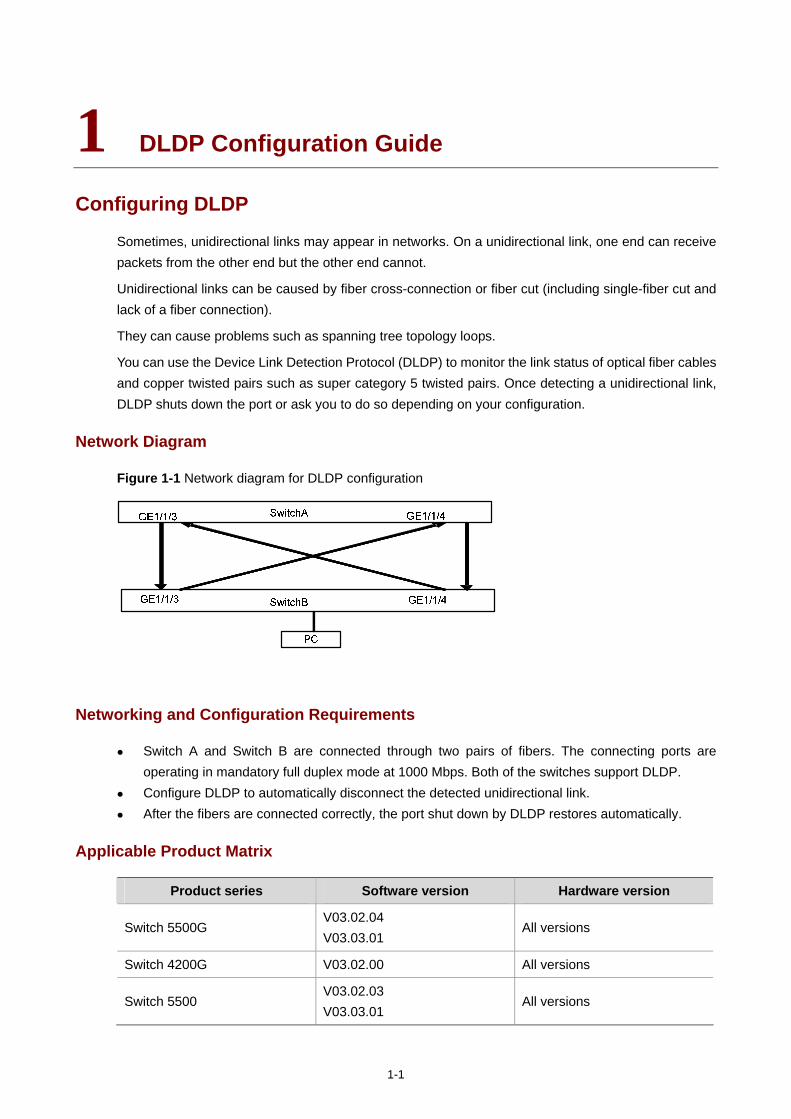
1-1
1 DLDP Configuration Guide
Configuring DLDP
Sometimes, unidirectional links may appear in networks. On a unidirectional link, one end can receive packets from the other end but the other end cannot.
Unidirectional links can be caused by fiber cross-connection or fiber cut (including single-fiber cut and lack of a fiber connection).
They can cause problems such as spanning tree topology loops.
You can use the Device Link Detection Protocol (DLDP) to monitor the link status of optical fiber cables and copper twisted pairs such as super category 5 twisted pairs. Once detecting a unidirectional link, DLDP shuts down the port or ask you to do so depending on your configuration.
Network Diagram
Figure 1-1 Network diagram for DLDP configuration
Networking and Configuration Requirements
Switch A and Switch B are connected through two pairs of fibers. The connecting ports are operating in mandatory full duplex mode at 1000 Mbps. Both of the switches support DLDP.
Configure DLDP to automatically disconnect the detected unidirectional link. After the fibers are connected correctly, the port shut down by DLDP restores automatically.
Applicable Product Matrix
Product series Software version Hardware version
Switch 5500G V03.02.04 V03.03.01
All versions
Switch 4200G V03.02.00 All versions
Switch 5500 V03.02.03 V03.03.01
All versions
1-2
Product series Software version Hardware version
Switch 4500 V03.02.00 V03.03.00
All versions
Configuration Procedure
Configure Switch A
# Configure the ports to work in mandatory full duplex mode at 1000 Mbps.
<SwitchA> system-view
[SwitchA] interface GigabitEthernet 1/1/3
[SwitchA-GigabitEthernet1/1/3] duplex full
[SwitchA-GigabitEthernet1/1/3] speed 1000
[SwitchA-GigabitEthernet1/1/3] quit
[SwitchA] interface GigabitEthernet 1/1/4
[SwitchA-GigabitEthernet1/1/4] duplex full
[SwitchA-GigabitEthernet1/1/4] speed 1000
[SwitchA-GigabitEthernet1/1/4] quit
# Enable DLDP globally.
[SwitchA] dldp enable
# Set the interval for sending DLDP packets to 15 seconds.
[SwitchA] dldp interval 15
# Configure DLDP to operate in enhanced mode.
[SwitchA] dldp work-mode enhance
# Configure DLDP to shut down a port automatically once a unidirectional link is detected on it.
[SwitchA] dldp unidirectional-shutdown auto
# Set the DelayDown timer to five seconds.
[SwitchA] dldp delaydown-timer 5
# Display the DLDP state.
[SwitchA] display dldp 1
# Restore the ports brought down by DLDP.
[SwitchA] dldp reset
Configure Switch B
The configuration on Switch B is the same as that on Switch A.
Complete Configuration
Configuration on Switch A #
dldp interval 15
dldp work-mode enhance
dldp delaydown-timer 5
#
1-3
interface Gigabitethernet 1/1/3
duplex full
speed 1000
dldp enable
#
interface Gigabitethernet 1/1/4
duplex full
speed 1000
dldp enable
Configuration on Switch B
The configuration on Switch B is the same as that on Switch A.
Precautions
1) When enabling DLDP on two connected devices, make sure that they are using the same software version. Otherwise, DLDP may malfunction.
2) When optical fibers are cross-connected, two or three ports are in the disable state, and the remaining ports are in the inactive state.
3) DLDP in the enhanced mode can identify unidirectional links caused by fiber cross-connection or fiber cut.
4) DLDP in the normal mode can identify only unidirectional links caused by fiber cross-connection.
i
Table of Contents
1 Auto Detect Configuration Guide·············································································································1-1 Auto Detect Implementation in Static Routing ························································································1-1
Network Diagram·····························································································································1-1 Networking and Configuration Requirements··················································································1-1 Applicable Product Matrix················································································································1-2 Configuration Procedure··················································································································1-2 Complete Configuration···················································································································1-3 Precautions······································································································································1-3
Auto Detect Implementation in VRRP·····································································································1-3 Network Diagram·····························································································································1-4 Networking and Configuration Requirements··················································································1-4 Applicable Product Matrix················································································································1-4 Configuration Procedure··················································································································1-4 Complete Configuration···················································································································1-5 Precautions······································································································································1-6
Auto Detect Implementation in VLAN Interface Backup ·········································································1-6 Network Diagram·····························································································································1-6 Networking and Configuration Requirements··················································································1-6 Applicable Product Matrix················································································································1-7 Configuration Procedure··················································································································1-7 Complete Configuration···················································································································1-8 Precautions······································································································································1-9
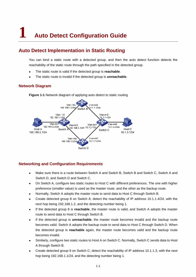
1-1
1 Auto Detect Configuration Guide
Auto Detect Implementation in Static Routing
You can bind a static route with a detected group, and then the auto detect function detects the reachability of the static route through the path specified in the detected group.
The static route is valid if the detected group is reachable. The static route is invalid if the detected group is unreachable.
Network Diagram
Figure 1-1 Network diagram of applying auto detect to static routing
Networking and Configuration Requirements
Make sure there is a route between Switch A and Switch B, Switch B and Switch C, Switch A and Switch D, and Switch D and Switch C.
On Switch A, configure two static routes to Host C with different preferences. The one with higher preference (smaller value) is used as the master route, and the other as the backup route.
Normally, Switch A adopts the master route to send data to Host C through Switch B. Create detected group 8 on Switch A; detect the reachability of IP address 10.1.1.4/24, with the
next hop being 192.168.1.2, and the detecting number being 1. If the detected group 8 is reachable, the master route is valid, and Switch A adopts the master
route to send data to Host C through Switch B. If the detected group is unreachable, the master route becomes invalid and the backup route
becomes valid. Switch A adopts the backup route to send data to Host C through Switch D. When the detected group is reachable again, the master route becomes valid and the backup route becomes invalid.
Similarly, configure two static routes to Host A on Switch C. Normally, Switch C sends data to Host A through Switch B.
Create detected group 9 on Switch C; detect the reachability of IP address 10.1.1.3, with the next hop being 192.168.1.1/24, and the detecting number being 1.
1-2
Applicable Product Matrix
Product series Software version Hardware version
Switch 5500 V03.02.03 V03.03.01
All versions
Switch 4500 V03.02.00 V03.03.00
All versions
Switch 5500G V03.02.04 V03.03.01
All versions
Configuration Procedure
Configure IP addresses for the interfaces according to Figure 1-1. The configuration procedure is omitted here.
Configure Switch A
# Enter system view.
<SwitchA> system-view
# Create detected group 8.
[SwitchA] detect-group 8
# Detect the reachability of 10.1.1.4, with the next hop being 192.168.1.2, and the detecting number being 1.
[SwitchA-detect-group-8] detect-list 1 ip address 10.1.1.4 nexthop 192.168.1.2
[SwitchA-detect-group-8] quit
# Configure a static route to Switch C, and set its preference to 60.
[SwitchA] ip route-static 10.1.1.4 24 192.168.1.2 preference 60
# Configure the master static route, which is valid when the detected group is reachable.
[SwitchA] ip route-static 10.1.3.1 24 192.168.1.2 detect-group 8
# Configure the backup static route, and set its preference to 80. The backup route is valid when the detected group is unreachable.
[SwitchA] ip route-static 10.1.3.1 24 192.168.3.2 preference 80
Configure Switch C
# Enter system view.
<SwitchC> system-view
# Create detected group 9.
[SwitchC] detect-group 9
# Detect the reachability of 10.1.1.3, with the next hop being 192.168.1.1/24, and the detecting number being 1.
[SwitchC-detect-group-9] detect-list 1 ip address 192.168.1.1 nexthop 10.1.1.3
[SwitchC-detect-group-9] quit
# Configure a static route to Switch A, and set its preference to 60.
[SwitchC] ip route-static 192.168.1.1 24 10.1.1.3 preference 60
1-3
# Configure the master route, which is valid when the detected group is reachable.
[SwitchC] ip route-static 192.168.2.1 24 10.1.1.3 detect-group 9
# Configure the backup static route, and set its preference to 80. The backup route is valid when the detected group is unreachable.
[SwitchC] ip route-static 192.168.2.1 24 10.1.2.2 preference 80
This configuration procedure only provides the auto-detect related configuration. To ensure the normal communication between Host A and Host C, corresponding static routes must already exist on Switch B and Switch D.
Complete Configuration
Configure Switch A #
detect-group 8
detect-list 1 ip address 10.1.1.4 nexthop 192.168.1.2
#
ip route-static 10.1.1.0 255.255.255.0 192.168.1.2 preference 60
ip route-static 10.1.3.0 255.255.255.0 192.168.1.2 preference 60 detect-group 8
ip route-static 10.1.3.0 255.255.255.0 192.168.3.2 preference 80
#
Configure Switch C #
detect-group 9
detect-list 1 ip address 192.168.1.1 nexthop 10.1.1.3
#
ip route-static 192.168.1.0 255.255.255.0 10.1.1.3 preference 60
ip route-static 192.168.2.0 255.255.255.0 10.1.1.3 preference 60 detect-group 9
ip route-static 192.168.2.0 255.255.255.0 10.1.2.2 preference 80
#
Precautions
In a network environment where the round trip delay of ICMP messages is longer than usual, you need to extend the timeout waiting for a reply for the group to ensure that your switch can correctly decide whether the group is reachable.
Auto Detect Implementation in VRRP
You can use the auto detect function on the master switch of a VRRP group to detect the routes from the master switch to other networks, and use the detection results (reachable/unreachable) to control the priority of the master switch, so as to realize the automatic master-backup switchover:
The master switch remains as master when the detected group is reachable.
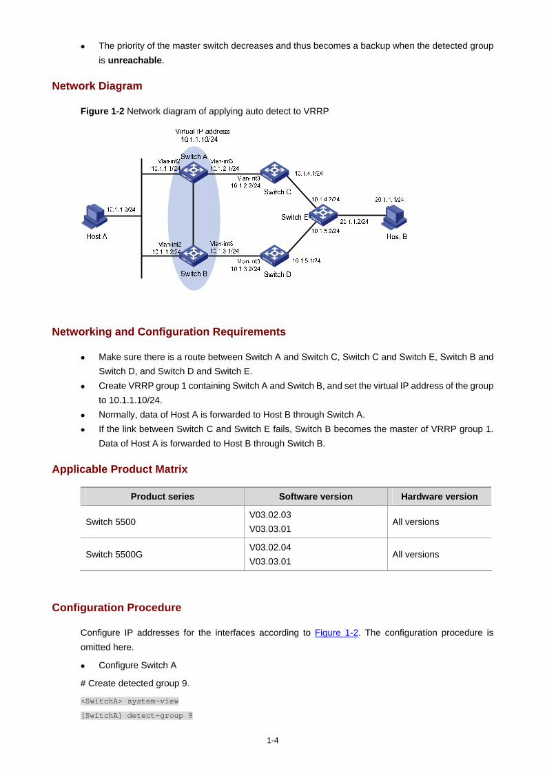
1-4
The priority of the master switch decreases and thus becomes a backup when the detected group is unreachable.
Network Diagram
Figure 1-2 Network diagram of applying auto detect to VRRP
Networking and Configuration Requirements
Make sure there is a route between Switch A and Switch C, Switch C and Switch E, Switch B and Switch D, and Switch D and Switch E.
Create VRRP group 1 containing Switch A and Switch B, and set the virtual IP address of the group to 10.1.1.10/24.
Normally, data of Host A is forwarded to Host B through Switch A. If the link between Switch C and Switch E fails, Switch B becomes the master of VRRP group 1.
Data of Host A is forwarded to Host B through Switch B.
Applicable Product Matrix
Product series Software version Hardware version
Switch 5500 V03.02.03 V03.03.01
All versions
Switch 5500G V03.02.04 V03.03.01
All versions
Configuration Procedure
Configure IP addresses for the interfaces according to Figure 1-2. The configuration procedure is omitted here.
Configure Switch A
# Create detected group 9.
<SwitchA> system-view
[SwitchA] detect-group 9
1-5
# Detect the reachability of 10.1.4.2, with the next hop being 10.1.2.2, and the detecting number being 1.
[SwitchA-detect-group-9] detect-list 1 ip address 10.1.4.2 nexthop 10.1.2.2
[SwitchA-detect-group-9] quit
# Configure an IP address for VLAN-interface 2.
[SwitchA] interface vlan-interface 2
[SwitchA-Vlan-interface2] ip address 10.1.1.1 24
# Enable VRRP on VLAN-interface 2, and set the virtual IP address of the VRRP group to 10.1.1.10.
[SwitchA-Vlan-interface2] vrrp vrid 1 virtual-ip 10.1.1.10
# Set the VRRP priority of Switch A to 110, and specify to decrease the priority by 20 when the result of detected group 9 is unreachable.
[SwitchA-Vlan-interface2] vrrp vrid 1 priority 110
[SwitchA-Vlan-interface2] vrrp vrid 1 track detect-group 9 reduced 20
Configure Switch B
# Configure an IP address for VLAN-interface 2.
<SwitchB> system-view
[SwitchB] interface vlan-interface 2
[SwitchB-Vlan-interface2] ip address 10.1.1.2 24
# Enable VRRP on VLAN-interface 2, and set the virtual IP address of the VRRP group to 10.1.1.10.
[SwitchB-Vlan-interface2] vrrp vrid 1 virtual-ip 10.1.1.10
# Set the VRRP priority of Switch B to 100.
[SwitchB-Vlan-interface2] vrrp vrid 1 priority 100
This configuration procedure only provides the auto-detect and VRRP related configuration. To ensure the operation of auto detect, you must ensure that Switch A and Switch E have at least one reachable route to each other.
Complete Configuration
Configure Switch A #
detect-group 9
detect-list 1 ip address 10.1.4.2 nexthop 10.1.2.2
#
interface Vlan-interface2
ip address 10.1.1.1 255.255.255.0
vrrp vrid 1 virtual-ip 10.1.1.10
vrrp vrid 1 priority 110
vrrp vrid 1 track detect-group 9 reduced 20
Configure Switch B #
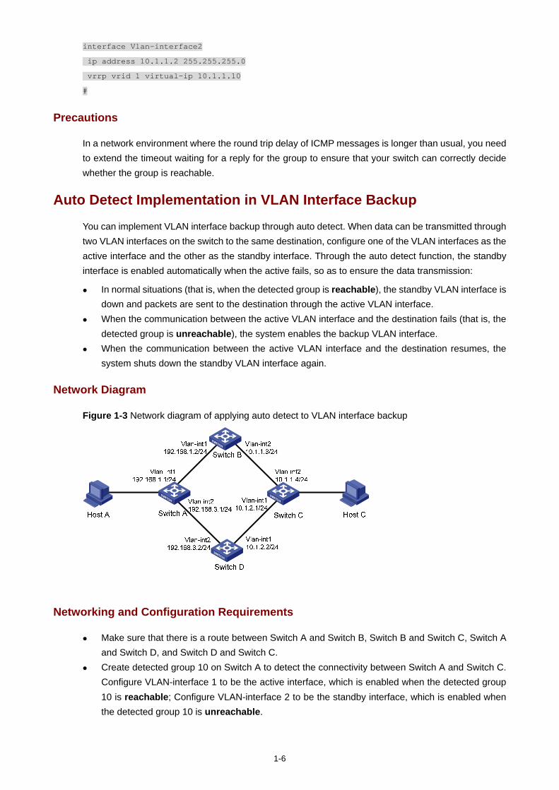
1-6
interface Vlan-interface2
ip address 10.1.1.2 255.255.255.0
vrrp vrid 1 virtual-ip 10.1.1.10
#
Precautions
In a network environment where the round trip delay of ICMP messages is longer than usual, you need to extend the timeout waiting for a reply for the group to ensure that your switch can correctly decide whether the group is reachable.
Auto Detect Implementation in VLAN Interface Backup
You can implement VLAN interface backup through auto detect. When data can be transmitted through two VLAN interfaces on the switch to the same destination, configure one of the VLAN interfaces as the active interface and the other as the standby interface. Through the auto detect function, the standby interface is enabled automatically when the active fails, so as to ensure the data transmission:
In normal situations (that is, when the detected group is reachable), the standby VLAN interface is down and packets are sent to the destination through the active VLAN interface.
When the communication between the active VLAN interface and the destination fails (that is, the detected group is unreachable), the system enables the backup VLAN interface.
When the communication between the active VLAN interface and the destination resumes, the system shuts down the standby VLAN interface again.
Network Diagram
Figure 1-3 Network diagram of applying auto detect to VLAN interface backup
Networking and Configuration Requirements
Make sure that there is a route between Switch A and Switch B, Switch B and Switch C, Switch A and Switch D, and Switch D and Switch C.
Create detected group 10 on Switch A to detect the connectivity between Switch A and Switch C. Configure VLAN-interface 1 to be the active interface, which is enabled when the detected group 10 is reachable; Configure VLAN-interface 2 to be the standby interface, which is enabled when the detected group 10 is unreachable.
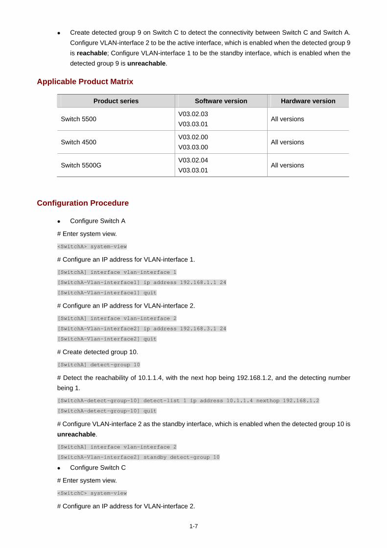
1-7
Create detected group 9 on Switch C to detect the connectivity between Switch C and Switch A. Configure VLAN-interface 2 to be the active interface, which is enabled when the detected group 9 is reachable; Configure VLAN-interface 1 to be the standby interface, which is enabled when the detected group 9 is unreachable.
Applicable Product Matrix
Product series Software version Hardware version
Switch 5500 V03.02.03 V03.03.01
All versions
Switch 4500 V03.02.00 V03.03.00
All versions
Switch 5500G V03.02.04 V03.03.01
All versions
Configuration Procedure
Configure Switch A
# Enter system view.
<SwitchA> system-view
# Configure an IP address for VLAN-interface 1.
[SwitchA] interface vlan-interface 1
[SwitchA-Vlan-interface1] ip address 192.168.1.1 24
[SwitchA-Vlan-interface1] quit
# Configure an IP address for VLAN-interface 2.
[SwitchA] interface vlan-interface 2
[SwitchA-Vlan-interface2] ip address 192.168.3.1 24
[SwitchA-Vlan-interface2] quit
# Create detected group 10.
[SwitchA] detect-group 10
# Detect the reachability of 10.1.1.4, with the next hop being 192.168.1.2, and the detecting number being 1.
[SwitchA-detect-group-10] detect-list 1 ip address 10.1.1.4 nexthop 192.168.1.2
[SwitchA-detect-group-10] quit
# Configure VLAN-interface 2 as the standby interface, which is enabled when the detected group 10 is unreachable.
[SwitchA] interface vlan-interface 2
[SwitchA-Vlan-interface2] standby detect-group 10
Configure Switch C
# Enter system view.
<SwitchC> system-view
# Configure an IP address for VLAN-interface 2.
1-8
[SwitchC] interface vlan-interface 2
[SwitchC-Vlan-interface2] ip address 10.1.1.4 24
[SwitchC-Vlan-interface2] quit
# Configure an IP address for VLAN-interface 1.
[SwitchC] interface vlan-interface 1
[SwitchC-Vlan-interface1] ip address 10.1.2.1 24
[SwitchC-Vlan-interface1] quit
# Create detected group 9.
[SwitchC] detect-group 9
# Detect the reachability of 192.168.1.1/24, with the next hop being 10.1.1.3, and the detecting number being 1.
[SwitchC-detect-group-9] detect-list 1 ip address 192.168.1.1 nexthop 10.1.1.3
[SwitchC-detect-group-9] quit
# Configure VLAN-interface 1 as the standby interface, which is enabled when the detected group 9 is unreachable.
[SwitchC] interface vlan-interface 1
[SwitchC-Vlan-interface1] standby detect-group 9
This configuration procedure only provides the auto-detect related configuration. To use auto detect function properly, a Switch A-to-Switch B-to-Switch C route must already exist on Switch A, and a Switch C-to-Switch B-to-Switch A route must already exist on Switch C.
Complete Configuration
Configure Switch A #
detect-group 10
detect-list 1 ip address 10.1.1.4 nexthop 192.168.1.2
#
vlan 1
#
vlan 2
#
interface Vlan-interface1
ip address 192.168.1.1 255.255.255.0
#
interface Vlan-interface2
standby detect-group 10
ip address 192.168.3.1 255.255.255.0
Configure Switch C #
detect-group 9

1-9
detect-list 1 ip address 192.168.1.1 nexthop 10.1.1.3
#
vlan 1
#
vlan 2
#
interface Vlan-interface1
standby detect-group 9
ip address 10.1.2.1 255.255.255.0
#
interface Vlan-interface2
ip address 10.1.1.4 255.255.255.0
#
Precautions
In a network environment where the round trip delay of ICMP messages is longer than usual, you need to extend the timeout waiting for a reply for the group to ensure that your switch can correctly decide whether the group is reachable.
i
Table of Contents
1 MSTP Configuring Guide ··························································································································1-1 Configuring MSTP···································································································································1-1
Network Diagram·····························································································································1-1 Networking and Configuration Requirements··················································································1-1 Applicable Product Matrix················································································································1-2 Configuration Procedure··················································································································1-2 Complete Configuration···················································································································1-3 Precautions······································································································································1-4
Configuring VLAN-VPN Tunneling··········································································································1-4 Network Diagram·····························································································································1-5 Networking and Configuration Requirements··················································································1-5 Applicable Product Matrix················································································································1-5 Configuration Procedure··················································································································1-5 Complete Configuration···················································································································1-6 Precautions······································································································································1-7
Configuring RSTP ···································································································································1-8 Network Diagram·····························································································································1-8 Networking and Configuration Requirements··················································································1-8 Applicable Product Matrix················································································································1-9 Configuration Procedure··················································································································1-9 Complete Configuration·················································································································1-11 Precautions····································································································································1-12
Configuring Digest Snooping and Rapid Transition··············································································1-13 Digest Snooping ····························································································································1-13 Rapid Transition ····························································································································1-13 Network Diagram···························································································································1-13 Networking and Configuration Requirements················································································1-13 Applicable Product Matrix··············································································································1-14 Configuration Procedure················································································································1-14 Complete Configuration·················································································································1-15 Precautions····································································································································1-15
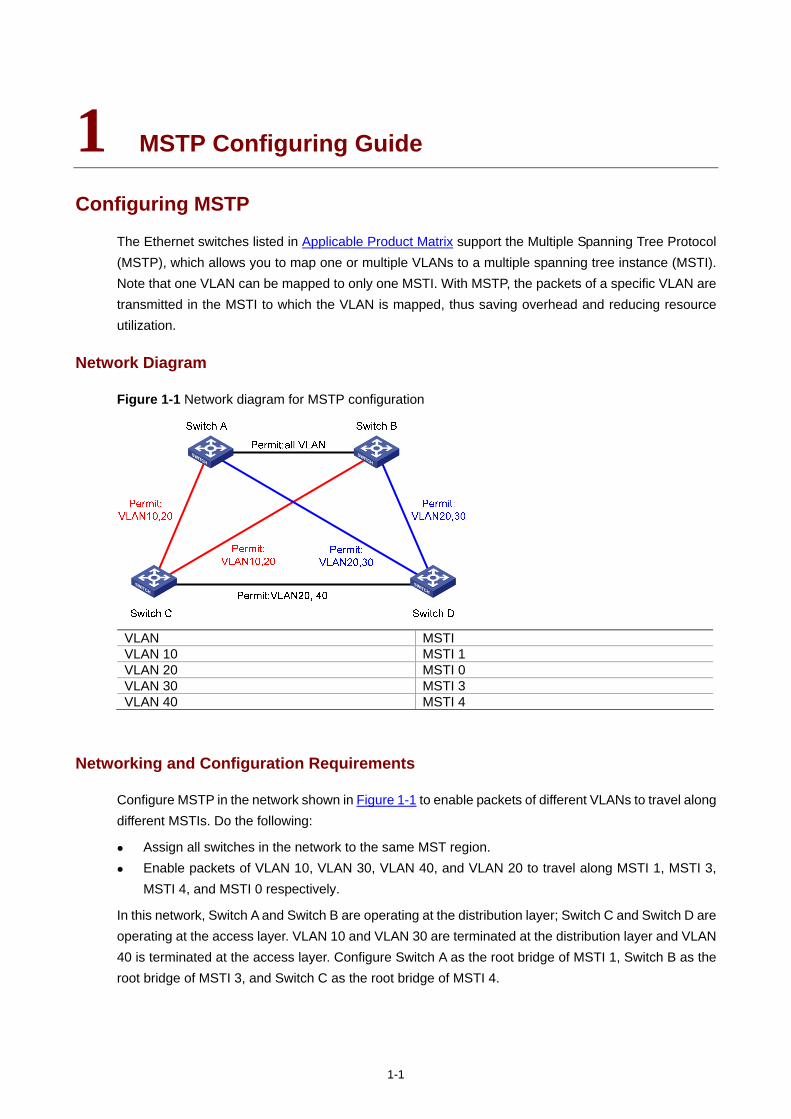
1-1
1 MSTP Configuring Guide
Configuring MSTP
The Ethernet switches listed in Applicable Product Matrix support the Multiple Spanning Tree Protocol (MSTP), which allows you to map one or multiple VLANs to a multiple spanning tree instance (MSTI). Note that one VLAN can be mapped to only one MSTI. With MSTP, the packets of a specific VLAN are transmitted in the MSTI to which the VLAN is mapped, thus saving overhead and reducing resource utilization.
Network Diagram
Figure 1-1 Network diagram for MSTP configuration
VLAN MSTI VLAN 10 MSTI 1 VLAN 20 MSTI 0 VLAN 30 MSTI 3 VLAN 40 MSTI 4
Networking and Configuration Requirements
Configure MSTP in the network shown in Figure 1-1 to enable packets of different VLANs to travel along different MSTIs. Do the following:
Assign all switches in the network to the same MST region. Enable packets of VLAN 10, VLAN 30, VLAN 40, and VLAN 20 to travel along MSTI 1, MSTI 3,
MSTI 4, and MSTI 0 respectively.
In this network, Switch A and Switch B are operating at the distribution layer; Switch C and Switch D are operating at the access layer. VLAN 10 and VLAN 30 are terminated at the distribution layer and VLAN 40 is terminated at the access layer. Configure Switch A as the root bridge of MSTI 1, Switch B as the root bridge of MSTI 3, and Switch C as the root bridge of MSTI 4.
1-2
Applicable Product Matrix
Product series Software version Hardware version
Switch 5500G V03.02.04 V03.03.01
All versions
Switch 5500 V03.02.03 V03.03.01
All versions
Switch 4500 V03.02.00 V03.03.00
All versions
Switch 4200G V03.02.00 All versions
Switch 4210 V03.01.00 V03.01.05
All versions
Configuration Procedure
1) Configuration on Switch A
# Enter MST region view.
<SwitchA> system-view
[SwitchA] stp region-configuration
# Configure the region name, VLAN-to-MSTI mapping, and revision level of the MST region.
[SwitchA-mst-region] region-name example
[SwitchA-mst-region] instance 1 vlan 10
[SwitchA-mst-region] instance 3 vlan 30
[SwitchA-mst-region] instance 4 vlan 40
[SwitchA-mst-region] revision-level 0
# Activate the MST region configuration manually.
[SwitchA-mst-region] active region-configuration
[SwitchA-mst-region] quit
# Specify Switch A as the root bridge of MSTI 1.
[SwitchA] stp instance 1 root primary
2) Configuration on Switch B
# Enter MST region view.
<SwitchB> system-view
[SwitchB] stp region-configuration
# Configure the region name, VLAN-to-MSTI mapping, and revision level of the MST region.
[SwitchB-mst-region] region-name example
[SwitchB-mst-region] instance 1 vlan 10
[SwitchB-mst-region] instance 3 vlan 30
[SwitchB-mst-region] instance 4 vlan 40
[SwitchB-mst-region] revision-level 0
# Activate the MST region configuration manually.
[SwitchB-mst-region] active region-configuration
1-3
[SwitchB-mst-region] quit
# Specify Switch B as the root bridge of MSTI 3.
[SwitchB] stp instance 3 root primary
3) Configuration on Switch C
# Configure the MST region.
<SwitchC> system-view
[SwitchC] stp region-configuration
[SwitchC-mst-region] region-name example
[SwitchC-mst-region] instance 1 vlan 10
[SwitchC-mst-region] instance 3 vlan 30
[SwitchC-mst-region] instance 4 vlan 40
[SwitchC-mst-region] revision-level 0
# Activate the MST region configuration manually.
[SwitchC-mst-region] active region-configuration
[SwitchC-mst-region] quit
# Specify Switch C as the root bridge of MSTI 4.
[SwitchC] stp instance 4 root primary
4) Configuration on Switch D
# Enter MST region view.
<SwitchD> system-view
[SwitchD] stp region-configuration
# Configure the MST region.
[SwitchD-mst-region] region-name example
[SwitchD-mst-region] instance 1 vlan 10
[SwitchD-mst-region] instance 3 vlan 30
[SwitchD-mst-region] instance 4 vlan 40
[SwitchD-mst-region] revision-level 0
# Activate the MST region configuration manually.
[SwitchD-mst-region] active region-configuration
Complete Configuration
Configuration on Switch A #
stp instance 1 root primary
stp region-configuration
region-name example
instance 1 vlan 10
instance 3 vlan 30
instance 4 vlan 40
active region-configuration
#
Configuration on Switch B #
1-4
stp instance 3 root primary
stp region-configuration
region-name example
instance 1 vlan 10
instance 3 vlan 30
instance 4 vlan 40
active region-configuration
#
Configuration on Switch C #
stp instance 4 root primary
stp region-configuration
region-name example
instance 1 vlan 10
instance 3 vlan 30
instance 4 vlan 40
active region-configuration
#
Configuration on Switch D #
stp region-configuration
instance 1 vlan 10
instance 3 vlan 30
instance 4 vlan 40
active region-configuration
#
Precautions
None
Configuring VLAN-VPN Tunneling
VLAN-VPN tunneling enables BPDUs to be transparently transmitted between geographically dispersed customer networks through a specific VLAN VPN over the service provider network. This allows the customer networks to share a spanning tree independent of that of the service provider network.
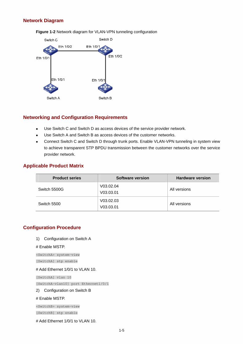
1-5
Network Diagram
Figure 1-2 Network diagram for VLAN-VPN tunneling configuration
Networking and Configuration Requirements
Use Switch C and Switch D as access devices of the service provider network. Use Switch A and Switch B as access devices of the customer networks. Connect Switch C and Switch D through trunk ports. Enable VLAN-VPN tunneling in system view
to achieve transparent STP BPDU transmission between the customer networks over the service provider network.
Applicable Product Matrix
Product series Software version Hardware version
Switch 5500G V03.02.04 V03.03.01
All versions
Switch 5500 V03.02.03 V03.03.01
All versions
Configuration Procedure
1) Configuration on Switch A
# Enable MSTP.
<SwitchA> system-view
[SwitchA] stp enable
# Add Ethernet 1/0/1 to VLAN 10.
[SwitchA] vlan 10
[SwitchA-vlan10] port Ethernet1/0/1
2) Configuration on Switch B
# Enable MSTP.
<SwitchB> system-view
[SwitchB] stp enable
# Add Ethernet 1/0/1 to VLAN 10.

1-6
[SwitchB] vlan 10
[SwitchB-vlan10] port Ethernet1/0/1
3) Configuration on Switch C
# Enable MSTP.
<SwitchC> system-view
[SwitchC] stp enable
# Enable VLAN-VPN tunneling.
[SwitchC] vlan-vpn tunnel
# Add Ethernet 1/0/1 to VLAN 10.
[SwitchC] vlan 10
[SwitchC-vlan10] port Ethernet1/0/1
[SwitchC-vlan10] quit
# Enable VLAN VPN.
[SwitchC] interface Ethernet1/0/1
[SwitchC-Ethernet1/0/1] vlan-vpn enable
[SwitchC-Ethernet1/0/1] quit
# Configure Ethernet 1/0/2 as a trunk port, and assign the port to VLAN 10.
[SwitchC] interface Ethernet1/0/2
[SwitchC-Ethernet1/0/2] port link-type trunk
[SwitchC-Ethernet1/0/2] port trunk permit vlan 10
4) Configuration on Switch D
# Enable MSTP.
<SwitchD> system-view
[SwitchD] stp enable
# Enable VLAN-VPN tunneling.
[SwitchD] vlan-vpn tunnel
# Add Ethernet 1/0/2 to VLAN 10.
[SwitchD] vlan 10
[SwitchD-vlan10] port Ethernet1/0/2
[SwitchD-vlan10] quit
# Enable VLAN VPN.
[SwitchD] interface Ethernet1/0/2
[SwitchD-Ethernet1/0/2] vlan-vpn enable
[SwitchD-Ethernet1/0/2] quit
# Configure Ethernet 1/0/1 as a trunk port, and assign the port to VLAN 10.
[SwitchD] interface Ethernet1/0/1
[SwitchD-Ethernet1/0/1] port link-type trunk
[SwitchD-Ethernet1/0/1] port trunk permit vlan 10
Complete Configuration
1) Configuration on Switch A #
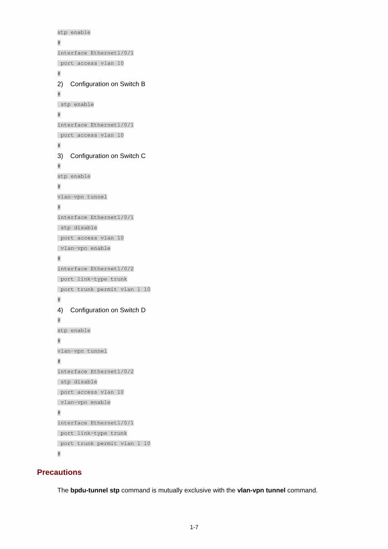
1-7
stp enable
#
interface Ethernet1/0/1
port access vlan 10
#
2) Configuration on Switch B #
stp enable
#
interface Ethernet1/0/1
port access vlan 10
#
3) Configuration on Switch C #
stp enable
#
vlan-vpn tunnel
#
interface Ethernet1/0/1
stp disable
port access vlan 10
vlan-vpn enable
#
interface Ethernet1/0/2
port link-type trunk
port trunk permit vlan 1 10
#
4) Configuration on Switch D #
stp enable
#
vlan-vpn tunnel
#
interface Ethernet1/0/2
stp disable
port access vlan 10
vlan-vpn enable
#
interface Ethernet1/0/1
port link-type trunk
port trunk permit vlan 1 10
#
Precautions
The bpdu-tunnel stp command is mutually exclusive with the vlan-vpn tunnel command.
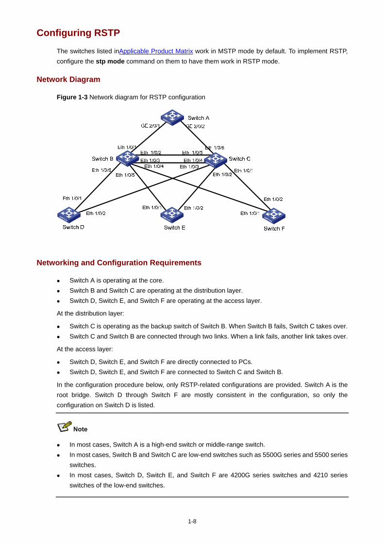
1-8
Configuring RSTP
The switches listed inApplicable Product Matrix work in MSTP mode by default. To implement RSTP, configure the stp mode command on them to have them work in RSTP mode.
Network Diagram
Figure 1-3 Network diagram for RSTP configuration
Networking and Configuration Requirements
Switch A is operating at the core. Switch B and Switch C are operating at the distribution layer. Switch D, Switch E, and Switch F are operating at the access layer.
At the distribution layer:
Switch C is operating as the backup switch of Switch B. When Switch B fails, Switch C takes over. Switch C and Switch B are connected through two links. When a link fails, another link takes over.
At the access layer:
Switch D, Switch E, and Switch F are directly connected to PCs. Switch D, Switch E, and Switch F are connected to Switch C and Switch B.
In the configuration procedure below, only RSTP-related configurations are provided. Switch A is the root bridge. Switch D through Switch F are mostly consistent in the configuration, so only the configuration on Switch D is listed.
In most cases, Switch A is a high-end switch or middle-range switch. In most cases, Switch B and Switch C are low-end switches such as 5500G series and 5500 series
switches. In most cases, Switch D, Switch E, and Switch F are 4200G series switches and 4210 series
switches of the low-end switches.
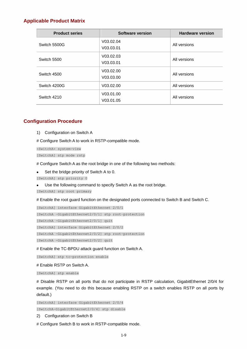
1-9
Applicable Product Matrix
Product series Software version Hardware version
Switch 5500G V03.02.04 V03.03.01
All versions
Switch 5500 V03.02.03 V03.03.01
All versions
Switch 4500 V03.02.00 V03.03.00
All versions
Switch 4200G V03.02.00 All versions
Switch 4210 V03.01.00 V03.01.05
All versions
Configuration Procedure
1) Configuration on Switch A
# Configure Switch A to work in RSTP-compatible mode.
<SwitchA> system-view
[SwitchA] stp mode rstp
# Configure Switch A as the root bridge in one of the following two methods:
Set the bridge priority of Switch A to 0. [SwitchA] stp priority 0
Use the following command to specify Switch A as the root bridge. [SwitchA] stp root primary
# Enable the root guard function on the designated ports connected to Switch B and Switch C.
[SwitchA] interface GigabitEthernet 2/0/1
[SwitchA -GigabitEthernet2/0/1] stp root-protection
[SwitchA -GigabitEthernet2/0/1] quit
[SwitchA] interface GigabitEthernet 2/0/2
[SwitchA -GigabitEthernet2/0/2] stp root-protection
[SwitchA -GigabitEthernet2/0/2] quit
# Enable the TC-BPDU attack guard function on Switch A.
[SwitchA] stp tc-protection enable
# Enable RSTP on Switch A.
[SwitchA] stp enable
# Disable RSTP on all ports that do not participate in RSTP calculation, GigabitEthernet 2/0/4 for example. (You need to do this because enabling RSTP on a switch enables RSTP on all ports by default.)
[SwitchA] interface GigabitEthernet 2/0/4
[SwitchA-GigabitEthernet2/0/4] stp disable
2) Configuration on Switch B
# Configure Switch B to work in RSTP-compatible mode.
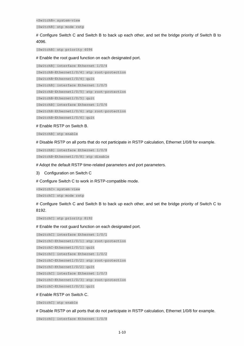
1-10
<SwitchB> system-view
[SwitchB] stp mode rstp
# Configure Switch C and Switch B to back up each other, and set the bridge priority of Switch B to 4096.
[SwitchB] stp priority 4096
# Enable the root guard function on each designated port.
[SwitchB] interface Ethernet 1/0/4
[SwitchB-Ethernet1/0/4] stp root-protection
[SwitchB-Ethernet1/0/4] quit
[SwitchB] interface Ethernet 1/0/5
[SwitchB-Ethernet1/0/5] stp root-protection
[SwitchB-Ethernet1/0/5] quit
[SwitchB] interface Ethernet 1/0/6
[SwitchB-Ethernet1/0/6] stp root-protection
[SwitchB-Ethernet1/0/6] quit
# Enable RSTP on Switch B.
[SwitchB] stp enable
# Disable RSTP on all ports that do not participate in RSTP calculation, Ethernet 1/0/8 for example.
[SwitchB] interface Ethernet 1/0/8
[SwitchB-Ethernet1/0/8] stp disable
# Adopt the default RSTP time-related parameters and port parameters.
3) Configuration on Switch C
# Configure Switch C to work in RSTP-compatible mode.
<SwitchC> system-view
[SwitchC] stp mode rstp
# Configure Switch C and Switch B to back up each other, and set the bridge priority of Switch C to 8192.
[SwitchC] stp priority 8192
# Enable the root guard function on each designated port.
[SwitchC] interface Ethernet 1/0/1
[SwitchC-Ethernet1/0/1] stp root-protection
[SwitchC-Ethernet1/0/1] quit
[SwitchC] interface Ethernet 1/0/2
[SwitchC-Ethernet1/0/2] stp root-protection
[SwitchC-Ethernet1/0/2] quit
[SwitchC] interface Ethernet 1/0/3
[SwitchC-Ethernet1/0/3] stp root-protection
[SwitchC-Ethernet1/0/3] quit
# Enable RSTP on Switch C.
[SwitchC] stp enable
# Disable RSTP on all ports that do not participate in RSTP calculation, Ethernet 1/0/8 for example.
[SwitchC] interface Ethernet 1/0/8
1-11
[SwitchC-Ethernet1/0/8] stp disable
# Adopt the default RSTP time-related parameters and port parameters.
4) Configuration on Switch D
# Configure Switch D to work in RSTP-compatible mode.
<SwitchD> system-view
[SwitchD] stp mode rstp
# Configure the ports directly connected to users as edge ports and enable the BPDU guard function on these ports. Take Ethernet 1/0/3 for example.
[SwitchD-Ethernet1/0/3] stp edged-port enable
[SwitchD-Ethernet1/0/3] quit
[SwitchD] stp bpdu-protection
# Enable RSTP on Switch D.
[SwitchD] stp enable
# Disable RSTP on all ports that do not participate in RSTP calculation, Ethernet 1/0/3 for example.
[SwitchD] interface Ethernet 1/0/3
[SwitchD-Ethernet1/0/3] stp disable
# Adopt the default RSTP time-related parameters and port parameters.
# The configuration on Switch E and Switch F are the same as that on Switch D.
Complete Configuration
1) Configuration on Switch A #
stp mode rstp
stp instance 0 priority 0
(stp instance 0 root primary)
stp TC-protection enable
stp enable
#
interface GigabitEthernet2/0/1
stp root-protection
#
interface GigabitEthernet2/0/2
stp root-protection
#
interface GigabitEthernet2/0/4
stp disable
#
2) Configuration on Switch B #
stp mode rstp
stp instance 0 priority 4096
stp enable
#
interface Ethernet1/0/4

1-12
stp root-protection
#
interface Ethernet1/0/5
stp root-protection
#
interface Ethernet1/0/6
stp root-protection
#
interface Ethernet1/0/8
stp disable
#
3) Configuration on Switch C #
stp mode rstp
stp instance 0 priority 8192
stp enable
#
interface Ethernet1/0/1
stp root-protection
#
interface Ethernet1/0/2
stp root-protection
#
interface Ethernet1/0/3
stp root-protection
#
interface Ethernet1/0/8
stp disable
#
4) Configuration on Switch D #
stp mode rstp
stp enable
#
interface Ethernet1/0/3
stp disable
interface Ethernet3/0/5
stp edged-port enable
stp bpdu-protection
#
Precautions
None
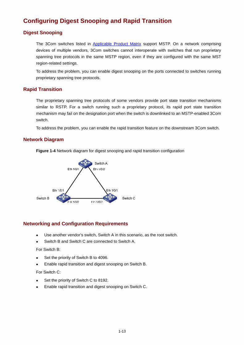
1-13
Configuring Digest Snooping and Rapid Transition
Digest Snooping
The 3Com switches listed in Applicable Product Matrix support MSTP. On a network comprising devices of multiple vendors, 3Com switches cannot interoperate with switches that run proprietary spanning tree protocols in the same MSTP region, even if they are configured with the same MST region-related settings.
To address the problem, you can enable digest snooping on the ports connected to switches running proprietary spanning tree protocols.
Rapid Transition
The proprietary spanning tree protocols of some vendors provide port state transition mechanisms similar to RSTP. For a switch running such a proprietary protocol, its rapid port state transition mechanism may fail on the designation port when the switch is downlinked to an MSTP-enabled 3Com switch.
To address the problem, you can enable the rapid transition feature on the downstream 3Com switch.
Network Diagram
Figure 1-4 Network diagram for digest snooping and rapid transition configuration
Networking and Configuration Requirements
Use another vendor’s switch, Switch A in this scenario, as the root switch. Switch B and Switch C are connected to Switch A.
For Switch B:
Set the priority of Switch B to 4096. Enable rapid transition and digest snooping on Switch B.
For Switch C:
Set the priority of Switch C to 8192. Enable rapid transition and digest snooping on Switch C.
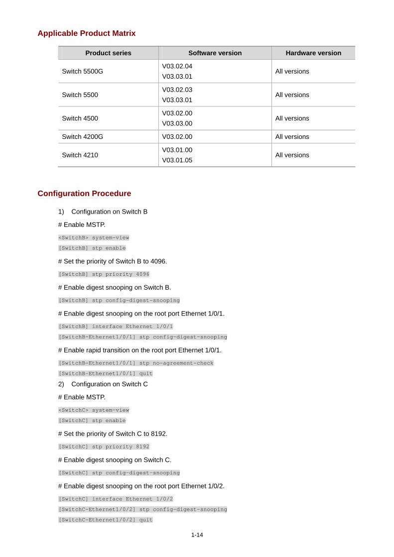
1-14
Applicable Product Matrix
Product series Software version Hardware version
Switch 5500G V03.02.04 V03.03.01
All versions
Switch 5500 V03.02.03 V03.03.01
All versions
Switch 4500 V03.02.00 V03.03.00
All versions
Switch 4200G V03.02.00 All versions
Switch 4210 V03.01.00 V03.01.05
All versions
Configuration Procedure
1) Configuration on Switch B
# Enable MSTP.
<SwitchB> system-view
[SwitchB] stp enable
# Set the priority of Switch B to 4096.
[SwitchB] stp priority 4096
# Enable digest snooping on Switch B.
[SwitchB] stp config-digest-snooping
# Enable digest snooping on the root port Ethernet 1/0/1.
[SwitchB] interface Ethernet 1/0/1
[SwitchB-Ethernet1/0/1] stp config-digest-snooping
# Enable rapid transition on the root port Ethernet 1/0/1.
[SwitchB-Ethernet1/0/1] stp no-agreement-check
[SwitchB-Ethernet1/0/1] quit
2) Configuration on Switch C
# Enable MSTP.
<SwitchC> system-view
[SwitchC] stp enable
# Set the priority of Switch C to 8192.
[SwitchC] stp priority 8192
# Enable digest snooping on Switch C.
[SwitchC] stp config-digest-snooping
# Enable digest snooping on the root port Ethernet 1/0/2.
[SwitchC] interface Ethernet 1/0/2
[SwitchC-Ethernet1/0/2] stp config-digest-snooping
[SwitchC-Ethernet1/0/2] quit
1-15
# Enable rapid transition on Ethernet 1/0/1.
[SwitchC] interface Ethernet 1/0/1
[SwitchC-Ethernet1/0/1] stp no-agreement-check
[SwitchC-Ethernet1/0/1] quit
Complete Configuration
1) Configuration on Switch B #
stp enable
stp instance 0 priority 4096
stp config-digest-snooping
#
interface Ethernet1/0/1
stp config-digest-snooping
stp no-agreement-check
#
2) Configuration on Switch C #
stp enable
stp instance 0 priority 8192
stp config-digest-snooping
#
interface Ethernet1/0/1
stp no-agreement-check
#
interface Ethernet1/0/2
stp config-digest-snooping
Precautions
The digest snooping feature is needed only when your switch is connected to another manufacturer’s switches adopting proprietary spanning tree protocols.
To enable the digest snooping feature successfully, you must first enable it on all the ports of your switch that are connected to another manufacturer’s switches adopting proprietary spanning tree protocols and then enable it globally.
To enable the digest snooping feature, the interconnected switches and another manufacturer’s switch adopting proprietary spanning tree protocols must be configured with exactly the same MST region-related configurations (including region name, revision level, and VLAN-to-MSTI mapping).
The digest snooping feature must be enabled on all the switch ports that connect to another manufacturer’s switches adopting proprietary spanning tree protocols in the same MST region.
The digest snooping feature is not applicable to boundary ports in an MST region. The digest snooping feature is not applicable to edge ports in an MST region. The rapid transition feature can be enabled only on root ports or alternate ports. You can enable rapid transition on a designated port, but the configuration cannot take effect on
the port.
i
Table of Contents
1 Routing Configuration Guide ···················································································································1-1 Configuring Static Routes ·······················································································································1-1
Network Diagram·····························································································································1-1 Networking and Configuration Requirements··················································································1-1 Applicable Product Matrix················································································································1-1 Configuration Procedure··················································································································1-2 Complete Configuration···················································································································1-2 Precautions······································································································································1-3
Configuring RIP·······································································································································1-3 Network Diagram·····························································································································1-3 Networking and Configuration Requirements··················································································1-4 Applicable Product Matrix················································································································1-4 Configuration Procedure··················································································································1-4 Complete Configuration···················································································································1-5 Precautions······································································································································1-6
Configuring OSPF···································································································································1-6 Network Diagram·····························································································································1-7 Networking and Configuration Requirements··················································································1-7 Applicable Product Matrix················································································································1-7 Configuration Procedure··················································································································1-7 Complete Configuration···················································································································1-8 Precautions····································································································································1-11
Configuring OSPF DR Election·············································································································1-11 Network Diagram···························································································································1-11 Networking and Configuration Requirements················································································1-11 Applicable Product Matrix··············································································································1-12 Configuration Procedure················································································································1-12 Complete Configuration·················································································································1-13 Precautions····································································································································1-14
Configuring a (Totally) Stub Area··········································································································1-15 Network Diagram···························································································································1-15 Networking and Configuration Requirements················································································1-15 Applicable Product Matrix··············································································································1-16 Configuration Procedure················································································································1-16 Complete Configuration·················································································································1-18 Precautions····································································································································1-21
Configuring a (Totally) NSSA Area ·······································································································1-21 Network Diagram···························································································································1-21 Networking and Configuration Requirements················································································1-21 Applicable Product Matrix··············································································································1-21 Configuration Procedure················································································································1-22 Complete Configuration·················································································································1-25 Precautions····································································································································1-27
ii
Configuring OSPF Route Summarization ·····························································································1-27 Network Diagram···························································································································1-28 Networking and Configuration Requirements················································································1-28 Applicable Product Matrix··············································································································1-28 Configuration Procedure················································································································1-28 Complete Configuration·················································································································1-31 Precautions····································································································································1-37
Configuring OSPF Virtual Link ··············································································································1-37 Network Diagram···························································································································1-38 Networking and Configuration Requirements················································································1-38 Applicable Product Matrix··············································································································1-38 Configuration Procedure················································································································1-38 Complete Configuration·················································································································1-39 Precautions····································································································································1-40
Configuring BGP Confederation Attribute·····························································································1-40 Network Diagram···························································································································1-41 Networking and Configuration Requirements················································································1-41 Applicable Product Matrix··············································································································1-41 Configuration Procedure················································································································1-41 Complete Configuration·················································································································1-42 Precautions····································································································································1-43
Configuring BGP RR·····························································································································1-43 Network Diagram···························································································································1-44 Networking and Configuration Requirements················································································1-44 Applicable Product Matrix··············································································································1-44 Configuration Procedure················································································································1-44 Complete Configuration·················································································································1-46 Precautions····································································································································1-47
Configuring BGP Path Selection···········································································································1-48 Network Diagram···························································································································1-48 Networking and Configuration Requirements················································································1-48 Applicable Product Matrix··············································································································1-48 Configuration Procedure················································································································1-48 Complete Configuration·················································································································1-52 Precautions····································································································································1-54
Configuring Routing Policies·················································································································1-54 Network Diagram···························································································································1-55 Networking and Configuration Requirements················································································1-55 Applicable Product Matrix··············································································································1-55 Configuration Procedure················································································································1-55 Complete Configuration·················································································································1-58 Precautions····································································································································1-59
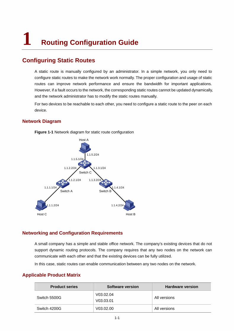
1-1
1 Routing Configuration Guide
Configuring Static Routes
A static route is manually configured by an administrator. In a simple network, you only need to configure static routes to make the network work normally. The proper configuration and usage of static routes can improve network performance and ensure the bandwidth for important applications. However, if a fault occurs to the network, the corresponding static routes cannot be updated dynamically, and the network administrator has to modify the static routes manually.
For two devices to be reachable to each other, you need to configure a static route to the peer on each device.
Network Diagram
Figure 1-1 Network diagram for static route configuration
1.1.5.2/24
Switch BSwitch A
Switch C
Host C
Host A
Host B
1.1.5.1/24
1.1.1.1/24
1.1.1.2/24
1.1.2.2/24
1.1.2.1/24 1.1.3.2/24
1.1.3.1/24
1.1.4.1/24
1.1.4.2/24
Networking and Configuration Requirements
A small company has a simple and stable office network. The company’s existing devices that do not support dynamic routing protocols. The company requires that any two nodes on the network can communicate with each other and that the existing devices can be fully utilized.
In this case, static routes can enable communication between any two nodes on the network.
Applicable Product Matrix
Product series Software version Hardware version
Switch 5500G V03.02.04 V03.03.01
All versions
Switch 4200G V03.02.00 All versions
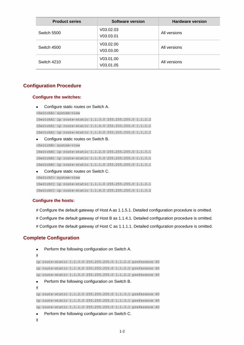
1-2
Product series Software version Hardware version
Switch 5500 V03.02.03 V03.03.01
All versions
Switch 4500 V03.02.00 V03.03.00
All versions
Switch 4210 V03.01.00 V03.01.05
All versions
Configuration Procedure
Configure the switches:
Configure static routes on Switch A. <SwitchA> system-view
[SwitchA] ip route-static 1.1.3.0 255.255.255.0 1.1.2.2
[SwitchA] ip route-static 1.1.4.0 255.255.255.0 1.1.2.2
[SwitchA] ip route-static 1.1.5.0 255.255.255.0 1.1.2.2
Configure static routes on Switch B. <SwitchB> system-view
[SwitchB] ip route-static 1.1.2.0 255.255.255.0 1.1.3.1
[SwitchB] ip route-static 1.1.5.0 255.255.255.0 1.1.3.1
[SwitchB] ip route-static 1.1.1.0 255.255.255.0 1.1.3.1
Configure static routes on Switch C. <SwitchC> system-view
[SwitchC] ip route-static 1.1.1.0 255.255.255.0 1.1.2.1
[SwitchC] ip route-static 1.1.4.0 255.255.255.0 1.1.3.2
Configure the hosts:
# Configure the default gateway of Host A as 1.1.5.1. Detailed configuration procedure is omitted.
# Configure the default gateway of Host B as 1.1.4.1. Detailed configuration procedure is omitted.
# Configure the default gateway of Host C as 1.1.1.1. Detailed configuration procedure is omitted.
Complete Configuration
Perform the following configuration on Switch A. #
ip route-static 1.1.3.0 255.255.255.0 1.1.2.2 preference 60
ip route-static 1.1.4.0 255.255.255.0 1.1.2.2 preference 60
ip route-static 1.1.5.0 255.255.255.0 1.1.2.2 preference 60
Perform the following configuration on Switch B. #
ip route-static 1.1.2.0 255.255.255.0 1.1.3.1 preference 60
ip route-static 1.1.5.0 255.255.255.0 1.1.3.1 preference 60
ip route-static 1.1.1.0 255.255.255.0 1.1.3.1 preference 60
Perform the following configuration on Switch C. #
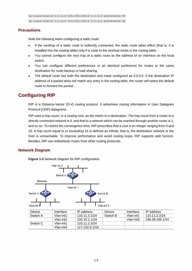
1-3
ip route-static 1.1.1.0 255.255.255.0 1.1.2.1 preference 60
ip route-static 1.1.4.0 255.255.255.0 1.1.3.2 preference 60
Precautions
Note the following when configuring a static route:
If the nexthop of a static route is indirectly connected, the static route takes effect (that is, it is installed into the routing table) only if a route to the nexthop exists in the routing table.
You cannot configure the next hop of a static route as the address of an interface on the local switch.
You can configure different preferences or an identical preference for routes to the same destination for route backup or load sharing.
The default route has both the destination and mask configured as 0.0.0.0. If the destination IP address of a packet does not match any entry in the routing table, the router will select the default route to forward the packet
Configuring RIP
RIP is a Distance-Vector (D-V) routing protocol. It advertises routing information in User Datagram Protocol (UDP) datagrams.
RIP uses a hop count, or a routing cost, as the metric to a destination. The hop count from a router to a directly connected network is 0, and that to a network which can be reached through another router is 1, and so on. To restrict the convergence time, RIP prescribes that a cost is an integer ranging from 0 and 15. A hop count equal to or exceeding 16 is defined as infinite; that is, the destination network or the host is unreachable. To improve performance and avoid routing loops, RIP supports split horizon. Besides, RIP can redistribute routes from other routing protocols.
Network Diagram
Figure 1-2 Network diagram for RIP configuration
Device Interface IP address Device Interface IP address Switch A Vlan-int1 110.11.2.1/24 Switch B Vlan-int1 110.11.2.2/24 Vlan-int2 155.10.1.1/24 Vlan-int3 196.38.165.1/24 Switch C Vlan-int1 110.11.2.3/24 Vlan-int4 117.102.0.1/16
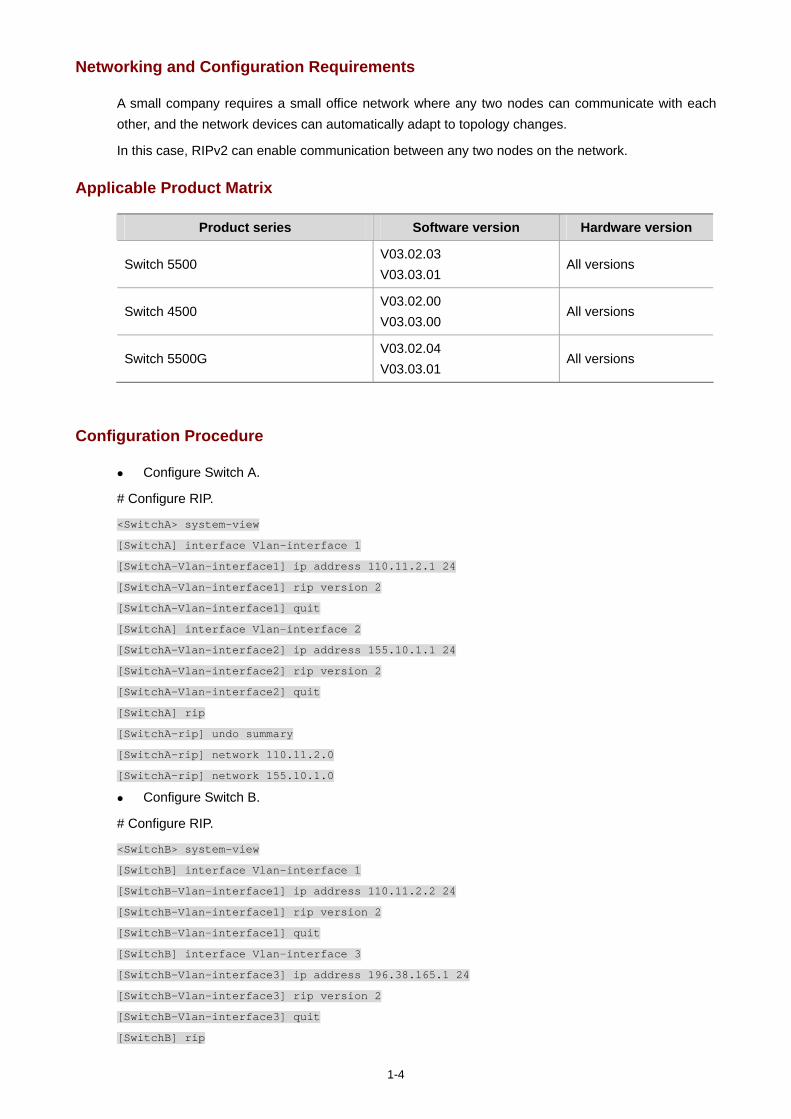
1-4
Networking and Configuration Requirements
A small company requires a small office network where any two nodes can communicate with each other, and the network devices can automatically adapt to topology changes.
In this case, RIPv2 can enable communication between any two nodes on the network.
Applicable Product Matrix
Product series Software version Hardware version
Switch 5500 V03.02.03 V03.03.01
All versions
Switch 4500 V03.02.00 V03.03.00
All versions
Switch 5500G V03.02.04 V03.03.01
All versions
Configuration Procedure
Configure Switch A.
# Configure RIP.
<SwitchA> system-view
[SwitchA] interface Vlan-interface 1
[SwitchA-Vlan-interface1] ip address 110.11.2.1 24
[SwitchA-Vlan-interface1] rip version 2
[SwitchA-Vlan-interface1] quit
[SwitchA] interface Vlan-interface 2
[SwitchA-Vlan-interface2] ip address 155.10.1.1 24
[SwitchA-Vlan-interface2] rip version 2
[SwitchA-Vlan-interface2] quit
[SwitchA] rip
[SwitchA-rip] undo summary
[SwitchA-rip] network 110.11.2.0
[SwitchA-rip] network 155.10.1.0
Configure Switch B.
# Configure RIP.
<SwitchB> system-view
[SwitchB] interface Vlan-interface 1
[SwitchB-Vlan-interface1] ip address 110.11.2.2 24
[SwitchB-Vlan-interface1] rip version 2
[SwitchB-Vlan-interface1] quit
[SwitchB] interface Vlan-interface 3
[SwitchB-Vlan-interface3] ip address 196.38.165.1 24
[SwitchB-Vlan-interface3] rip version 2
[SwitchB-Vlan-interface3] quit
[SwitchB] rip
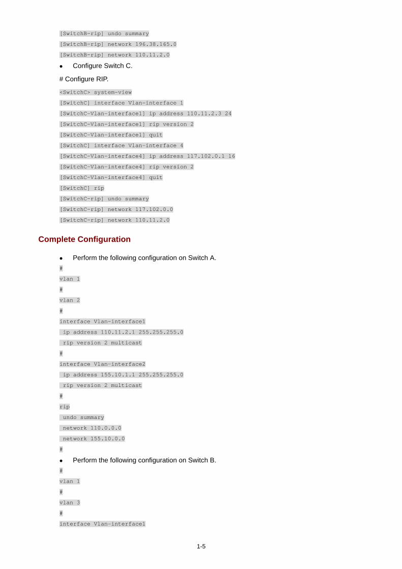
1-5
[SwitchB-rip] undo summary
[SwitchB-rip] network 196.38.165.0
[SwitchB-rip] network 110.11.2.0
Configure Switch C.
# Configure RIP.
<SwitchC> system-view
[SwitchC] interface Vlan-interface 1
[SwitchC-Vlan-interface1] ip address 110.11.2.3 24
[SwitchC-Vlan-interface1] rip version 2
[SwitchC-Vlan-interface1] quit
[SwitchC] interface Vlan-interface 4
[SwitchC-Vlan-interface4] ip address 117.102.0.1 16
[SwitchC-Vlan-interface4] rip version 2
[SwitchC-Vlan-interface4] quit
[SwitchC] rip
[SwitchC-rip] undo summary
[SwitchC-rip] network 117.102.0.0
[SwitchC-rip] network 110.11.2.0
Complete Configuration
Perform the following configuration on Switch A. #
vlan 1
#
vlan 2
#
interface Vlan-interface1
ip address 110.11.2.1 255.255.255.0
rip version 2 multicast
#
interface Vlan-interface2
ip address 155.10.1.1 255.255.255.0
rip version 2 multicast
#
rip
undo summary
network 110.0.0.0
network 155.10.0.0
#
Perform the following configuration on Switch B. #
vlan 1
#
vlan 3
#
interface Vlan-interface1
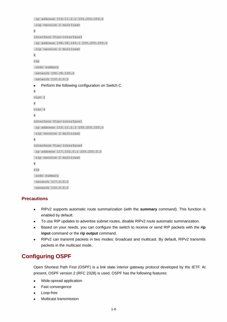
1-6
ip address 110.11.2.2 255.255.255.0
rip version 2 multicast
#
interface Vlan-interface3
ip address 196.38.165.1 255.255.255.0
rip version 2 multicast
#
rip
undo summary
network 196.38.165.0
network 110.0.0.0
Perform the following configuration on Switch C. #
vlan 1
#
vlan 4
#
interface Vlan-interface1
ip address 110.11.2.3 255.255.255.0
rip version 2 multicast
#
interface Vlan-interface4
ip address 117.102.0.1 255.255.0.0
rip version 2 multicast
#
rip
undo summary
network 117.0.0.0
network 110.0.0.0
Precautions
RIPv2 supports automatic route summarization (with the summary command). This function is enabled by default.
To use RIP updates to advertise subnet routes, disable RIPv2 route automatic summarization. Based on your needs, you can configure the switch to receive or send RIP packets with the rip
input command or the rip output command. RIPv2 can transmit packets in two modes: broadcast and multicast. By default, RIPv2 transmits
packets in the multicast mode.
Configuring OSPF
Open Shortest Path First (OSPF) is a link state interior gateway protocol developed by the IETF. At present, OSPF version 2 (RFC 2328) is used. OSPF has the following features:
Wide-spread application Fast convergence Loop-free Multicast transmission
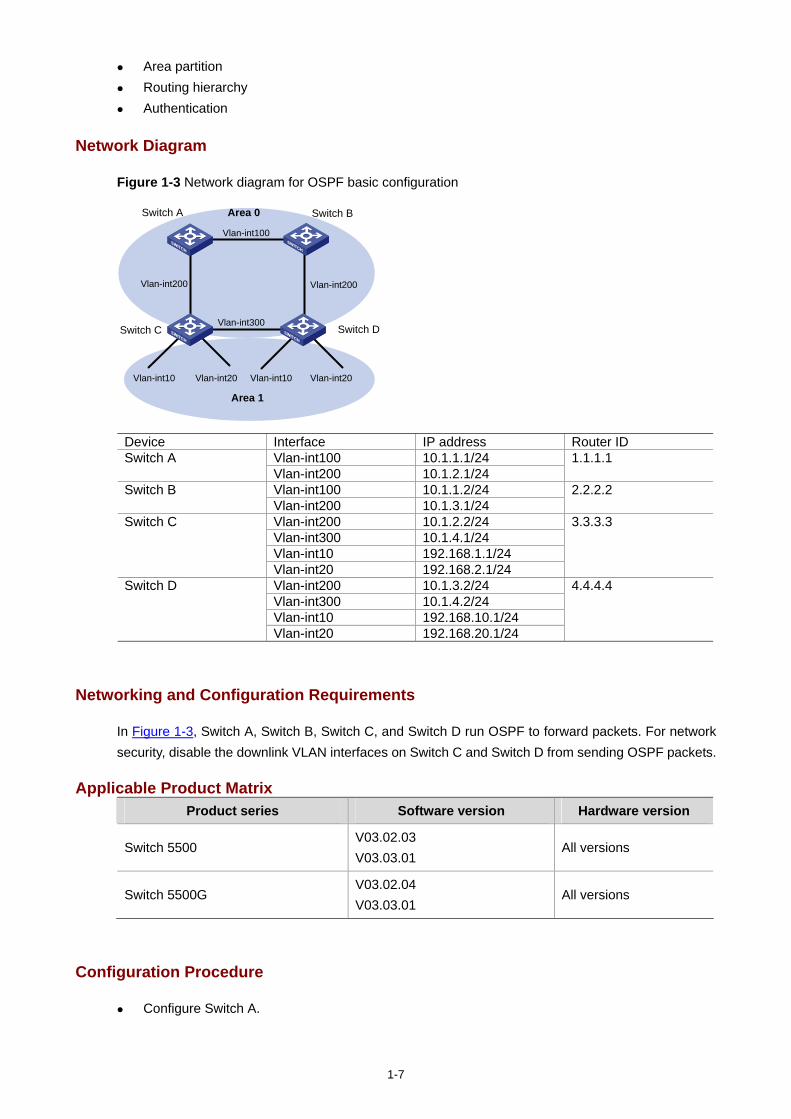
1-7
Area partition Routing hierarchy Authentication
Network Diagram
Figure 1-3 Network diagram for OSPF basic configuration
Area 0
Area 1
Switch C
Vlan-int100
Switch BSwitch A
Switch D
Vlan-int200 Vlan-int200
Vlan-int300
Vlan-int10 Vlan-int20 Vlan-int10 Vlan-int20
Device Interface IP address Router ID Vlan-int100 10.1.1.1/24 Switch A Vlan-int200 10.1.2.1/24
1.1.1.1
Vlan-int100 10.1.1.2/24 Switch B Vlan-int200 10.1.3.1/24
2.2.2.2
Vlan-int200 10.1.2.2/24 Vlan-int300 10.1.4.1/24 Vlan-int10 192.168.1.1/24
Switch C
Vlan-int20 192.168.2.1/24
3.3.3.3
Vlan-int200 10.1.3.2/24 Vlan-int300 10.1.4.2/24 Vlan-int10 192.168.10.1/24
Switch D
Vlan-int20 192.168.20.1/24
4.4.4.4
Networking and Configuration Requirements
In Figure 1-3, Switch A, Switch B, Switch C, and Switch D run OSPF to forward packets. For network security, disable the downlink VLAN interfaces on Switch C and Switch D from sending OSPF packets.
Applicable Product MatrixProduct series Software version Hardware version
Switch 5500 V03.02.03 V03.03.01
All versions
Switch 5500G V03.02.04 V03.03.01
All versions
Configuration Procedure
Configure Switch A.
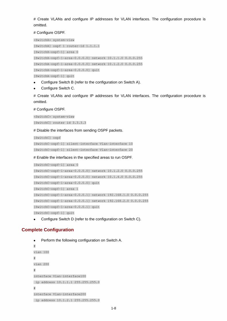
1-8
# Create VLANs and configure IP addresses for VLAN interfaces. The configuration procedure is omitted.
# Configure OSPF.
<SwitchA> system-view
[SwitchA] ospf 1 router-id 1.1.1.1
[SwitchA-ospf-1] area 0
[SwitchA-ospf-1-area-0.0.0.0] network 10.1.1.0 0.0.0.255
[SwitchA-ospf-1-area-0.0.0.0] network 10.1.2.0 0.0.0.255
[SwitchA-ospf-1-area-0.0.0.0] quit
[SwitchA-ospf-1] quit
Configure Switch B (refer to the configuration on Switch A). Configure Switch C.
# Create VLANs and configure IP addresses for VLAN interfaces. The configuration procedure is omitted.
# Configure OSPF.
<SwitchC> system-view
[SwitchC] router id 3.3.3.3
# Disable the interfaces from sending OSPF packets.
[SwitchC] ospf
[SwitchC-ospf-1] silent-interface Vlan-interface 10
[SwitchC-ospf-1] silent-interface Vlan-interface 20
# Enable the interfaces in the specified areas to run OSPF.
[SwitchC-ospf-1] area 0
[SwitchC-ospf-1-area-0.0.0.0] network 10.1.2.0 0.0.0.255
[SwitchC-ospf-1-area-0.0.0.0] network 10.1.4.0 0.0.0.255
[SwitchC-ospf-1-area-0.0.0.0] quit
[SwitchC-ospf-1] area 1
[SwitchC-ospf-1-area-0.0.0.1] network 192.168.1.0 0.0.0.255
[SwitchC-ospf-1-area-0.0.0.1] network 192.168.2.0 0.0.0.255
[SwitchC-ospf-1-area-0.0.0.1] quit
[SwitchC-ospf-1] quit
Configure Switch D (refer to the configuration on Switch C).
Complete Configuration
Perform the following configuration on Switch A. #
vlan 100
#
vlan 200
#
interface Vlan-interface100
ip address 10.1.1.1 255.255.255.0
#
interface Vlan-interface200
ip address 10.1.2.1 255.255.255.0

1-9
#
ospf 1 router-id 1.1.1.1
area 0.0.0.0
network 10.1.1.0 0.0.0.255
network 10.1.2.0 0.0.0.255
#
Perform the following configuration on Switch B. #
vlan 100
#
vlan 200
#
interface Vlan-interface100
ip address 10.1.1.2 255.255.255.0
#
interface Vlan-interface200
ip address 10.1.3.1 255.255.255.0
#
ospf 1 router-id 2.2.2.2
area 0.0.0.0
network 10.1.1.0 0.0.0.255
network 10.1.3.0 0.0.0.255
#
Perform the following configuration on Switch C. #
router id 3.3.3.3
#
vlan 10
#
vlan 20
#
vlan 200
#
vlan 300
#
interface Vlan-interface10
ip address 192.168.1.1 255.255.255.0
#
interface Vlan-interface20
ip address 192.168.2.1 255.255.255.0
#
interface Vlan-interface200
ip address 10.1.2.2 255.255.255.0
#
interface Vlan-interface300
ip address 10.1.4.1 255.255.255.0
#

1-10
ospf 1
silent-interface Vlan-interface10
silent-interface Vlan-interface20
area 0.0.0.1
network 192.168.1.0 0.0.0.255
network 192.168.2.0 0.0.0.255
#
area 0.0.0.0
network 10.1.2.0 0.0.0.255
network 10.1.4.0 0.0.0.255
#
Perform the following configuration on Switch D. #
router id 4.4.4.4
#
vlan 10
#
vlan 20
#
vlan 200
#
vlan 300
#
interface Vlan-interface10
ip address 192.168.10.1 255.255.255.0
#
interface Vlan-interface20
ip address 192.168.20.1 255.255.255.0
#
interface Vlan-interface200
ip address 10.1.3.2 255.255.255.0
#
interface Vlan-interface300
ip address 10.1.4.2 255.255.255.0
#
ospf 1
silent-interface Vlan-interface10
silent-interface Vlan-interface20
area 0.0.0.1
network 192.168.10.0 0.0.0.255
network 192.168.20.0 0.0.0.255
#
area 0.0.0.0
network 10.1.3.0 0.0.0.255
network 10.1.4.0 0.0.0.255
#
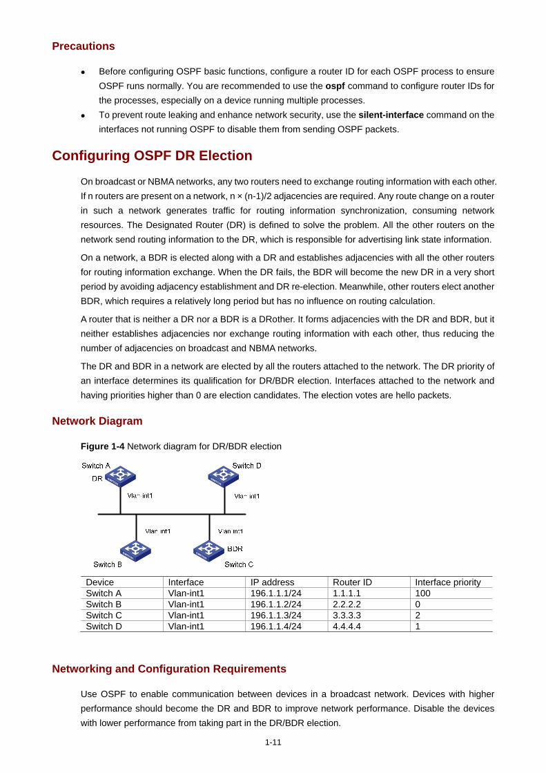
1-11
Precautions
Before configuring OSPF basic functions, configure a router ID for each OSPF process to ensure OSPF runs normally. You are recommended to use the ospf command to configure router IDs for the processes, especially on a device running multiple processes.
To prevent route leaking and enhance network security, use the silent-interface command on the interfaces not running OSPF to disable them from sending OSPF packets.
Configuring OSPF DR Election
On broadcast or NBMA networks, any two routers need to exchange routing information with each other. If n routers are present on a network, n × (n-1)/2 adjacencies are required. Any route change on a router in such a network generates traffic for routing information synchronization, consuming network resources. The Designated Router (DR) is defined to solve the problem. All the other routers on the network send routing information to the DR, which is responsible for advertising link state information.
On a network, a BDR is elected along with a DR and establishes adjacencies with all the other routers for routing information exchange. When the DR fails, the BDR will become the new DR in a very short period by avoiding adjacency establishment and DR re-election. Meanwhile, other routers elect another BDR, which requires a relatively long period but has no influence on routing calculation.
A router that is neither a DR nor a BDR is a DRother. It forms adjacencies with the DR and BDR, but it neither establishes adjacencies nor exchange routing information with each other, thus reducing the number of adjacencies on broadcast and NBMA networks.
The DR and BDR in a network are elected by all the routers attached to the network. The DR priority of an interface determines its qualification for DR/BDR election. Interfaces attached to the network and having priorities higher than 0 are election candidates. The election votes are hello packets.
Network Diagram
Figure 1-4 Network diagram for DR/BDR election
Device Interface IP address Router ID Interface priority Switch A Vlan-int1 196.1.1.1/24 1.1.1.1 100 Switch B Vlan-int1 196.1.1.2/24 2.2.2.2 0 Switch C Vlan-int1 196.1.1.3/24 3.3.3.3 2 Switch D Vlan-int1 196.1.1.4/24 4.4.4.4 1
Networking and Configuration Requirements
Use OSPF to enable communication between devices in a broadcast network. Devices with higher performance should become the DR and BDR to improve network performance. Disable the devices with lower performance from taking part in the DR/BDR election.
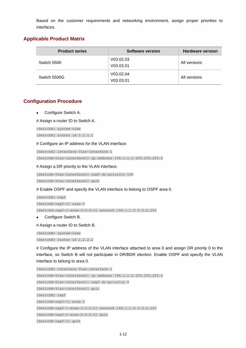
1-12
Based on the customer requirements and networking environment, assign proper priorities to interfaces.
Applicable Product Matrix
Product series Software version Hardware version
Switch 5500 V03.02.03 V03.03.01
All versions
Switch 5500G V03.02.04 V03.03.01
All versions
Configuration Procedure
Configure Switch A.
# Assign a router ID to Switch A.
<SwitchA> system-view
[SwitchA] router id 1.1.1.1
# Configure an IP address for the VLAN interface.
[SwitchA] interface Vlan-interface 1
[SwitchA-Vlan-interface1] ip address 196.1.1.1 255.255.255.0
# Assign a DR priority to the VLAN interface.
[SwitchA-Vlan-interface1] ospf dr-priority 100
[SwitchA-Vlan-interface1] quit
# Enable OSPF and specify the VLAN interface to belong to OSPF area 0.
[SwitchA] ospf
[SwitchA-ospf-1] area 0
[SwitchA-ospf-1-area-0.0.0.0] network 196.1.1.0 0.0.0.255
Configure Switch B.
# Assign a router ID to Switch B.
<SwitchB> system-view
[SwitchB] router id 2.2.2.2
# Configure the IP address of the VLAN interface attached to area 0 and assign DR priority 0 to the interface, so Switch B will not participate in DR/BDR election. Enable OSPF and specify the VLAN interface to belong to area 0.
[SwitchB] interface Vlan-interface 1
[SwitchB-Vlan-interface1] ip address 196.1.1.2 255.255.255.0
[SwitchB-Vlan-interface1] ospf dr-priority 0
[SwitchB-Vlan-interface1] quit
[SwitchB] ospf
[SwitchB-ospf-1] area 0
[SwitchB-ospf-1-area-0.0.0.0] network 196.1.1.0 0.0.0.255
[SwitchB-ospf-1-area-0.0.0.0] quit
[SwitchB-ospf-1] quit
1-13
Configure Switch C.
# Assign a router ID to Switch C.
<SwitchC> system-view
[SwitchC] router id 3.3.3.3
# Configure an IP address for the VLAN interface.
[SwitchC] interface Vlan-interface 1
[SwitchC-Vlan-interface1] ip address 196.1.1.3 255.255.255.0
# Assign a DR priority to the VLAN interface.
[SwitchC-Vlan-interface1] ospf dr-priority 2
[SwitchC-Vlan-interface1] quit
# Enable OSPF and specify the VLAN interface to belong to area 0.
[SwitchC] ospf
[SwitchC-ospf-1] area 0
[SwitchC-ospf-1-area-0.0.0.0] network 196.1.1.0 0.0.0.255
Configure Switch D.
# Assign a router ID to Switch D.
<SwitchD> system-view
[SwitchD] router id 4.4.4.4
# Configure an IP address for the VLAN interface.
[SwitchD] interface Vlan-interface 1
[SwitchD-Vlan-interface1] ip address 196.1.1.4 255.255.255.0
[SwitchD-Vlan-interface1] quit
# Enable OSPF and specify the VLAN interface to belong to area 0.
[SwitchD] ospf
[SwitchD-ospf-1] area 0
[SwitchD-ospf-1-area-0.0.0.0] network 196.1.1.0 0.0.0.255
Complete Configuration
Perform the following configuration on Switch A. #
router id 1.1.1.1
#
vlan 1
#
interface Vlan-interface 1
ip address 196.1.1.1 255.255.255.0
ospf dr-priority 100
#
ospf 1
area 0.0.0.0
network 196.1.1.0 0.0.0.255
Perform the following configuration on Switch B. #
1-14
router id 2.2.2.2
#
vlan 1
#
interface Vlan-interface 1
ip address 196.1.1.2 255.255.255.0
ospf dr-priority 0
#
ospf 1
area 0.0.0.0
network 196.1.1.0 0.0.0.255
Perform the following configuration on Switch C. #
router id 3.3.3.3
#
vlan 1
#
interface Vlan-interface 1
ip address 196.1.1.3 255.255.255.0
ospf dr-priority 2
#
ospf 1
area 0.0.0.0
network 196.1.1.0 0.0.0.255
Perform the following configuration on Switch D. #
router id 4.4.4.4
#
vlan 1
#
interface Vlan-interface 1
ip address 196.1.1.4 255.255.255.0
#
ospf 1
area 0.0.0.0
network 196.1.1.0 0.0.0.255
Precautions
The DR election is performed only on broadcast and NBMA interfaces rather than P2P or P2MP interfaces.
A DR is an interface of a router and belongs to a single network segment. A router’s interface may be a DR, while another interface of the router may be a BDR or DRother.
The DR priority of a router interface affects the DR and BDR election. However, it does not effect the election immediately after the DR and BDR election ends. A new DR priority assigned to a router interface takes effect at the time of next DR and BDR election.
A DR may not be a router interface with the highest priority in a network, and a BDR may not be a router interface with the second highest priority.
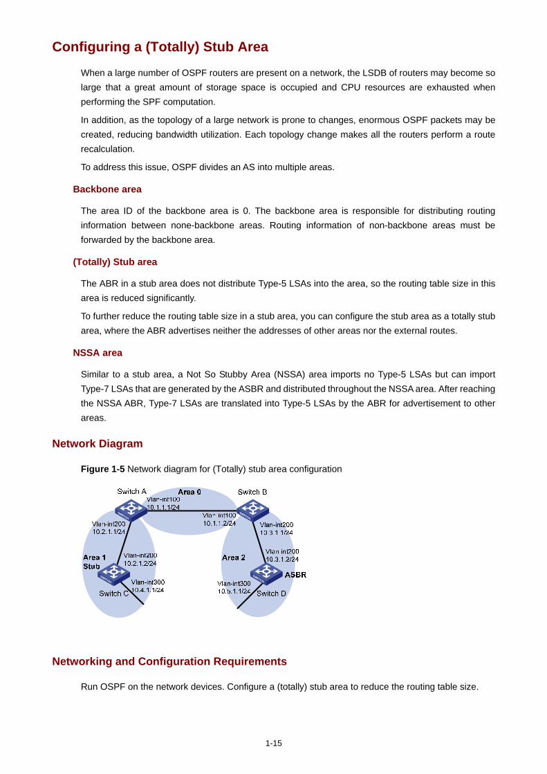
1-15
Configuring a (Totally) Stub Area
When a large number of OSPF routers are present on a network, the LSDB of routers may become so large that a great amount of storage space is occupied and CPU resources are exhausted when performing the SPF computation.
In addition, as the topology of a large network is prone to changes, enormous OSPF packets may be created, reducing bandwidth utilization. Each topology change makes all the routers perform a route recalculation.
To address this issue, OSPF divides an AS into multiple areas.
Backbone area
The area ID of the backbone area is 0. The backbone area is responsible for distributing routing information between none-backbone areas. Routing information of non-backbone areas must be forwarded by the backbone area.
(Totally) Stub area
The ABR in a stub area does not distribute Type-5 LSAs into the area, so the routing table size in this area is reduced significantly.
To further reduce the routing table size in a stub area, you can configure the stub area as a totally stub area, where the ABR advertises neither the addresses of other areas nor the external routes.
NSSA area
Similar to a stub area, a Not So Stubby Area (NSSA) area imports no Type-5 LSAs but can import Type-7 LSAs that are generated by the ASBR and distributed throughout the NSSA area. After reaching the NSSA ABR, Type-7 LSAs are translated into Type-5 LSAs by the ABR for advertisement to other areas.
Network Diagram
Figure 1-5 Network diagram for (Totally) stub area configuration
Networking and Configuration Requirements
Run OSPF on the network devices. Configure a (totally) stub area to reduce the routing table size.
1-16
Applicable Product Matrix
Product series Software version Hardware version
Switch 5500 V03.02.03 V03.03.01
All versions
Switch 5500G V03.02.04 V03.03.01
All versions
Configuration Procedure
Non-backbone area and backbone area configuration (area 1 is a non-backbone area)
Configure Switch A.
# Create VLANs and configure IP addresses for the VLAN interfaces. The configuration procedure is omitted.
# Configure OSPF for area 1.
<SwitchA> system-view
[SwitchA] ospf 1 router-id 1.1.1.1
[SwitchA-ospf-1] area 1
[SwitchA-ospf-1-area-0.0.0.1] network 10.2.1.0 0.0.0.255
# Configure OSPF for the backbone area.
[SwitchA-ospf-1] area 0
[SwitchA-ospf-1-area-0.0.0.0] network 10.1.1.0 0.0.0.255
Configure Switch B (refer to the configuration on Switch A). Configure Switch C.
# Create VLANs and configure IP addresses for the VLAN interfaces. The configuration procedure is omitted.
# Configure OSPF for area 1.
<SwitchC> system-view
[SwitchC] ospf 1 router-id 3.3.3.3
[SwitchC-ospf-1] area 1
[SwitchC-ospf-1-area-0.0.0.1] network 10.2.1.0 0.0.0.255
[SwitchC-ospf-1-area-0.0.0.1] network 10.4.1.0 0.0.0.255
Configure Switch D.
# Create VLANs and configure IP addresses for the VLAN interfaces. The configuration procedure is omitted.
# Configure a static route of 1.0.0.0/8.
<SwitchD> system-view
[SwitchD] ip route-static 1.0.0.0 8 10.5.1.2
# Configure OSPF for area 2.
[SwitchD] ospf 1 router-id 4.4.4.4
[SwitchD-ospf-1] area 2
[SwitchD-ospf-1-area-0.0.0.2] network 10.3.1.0 0.0.0.255
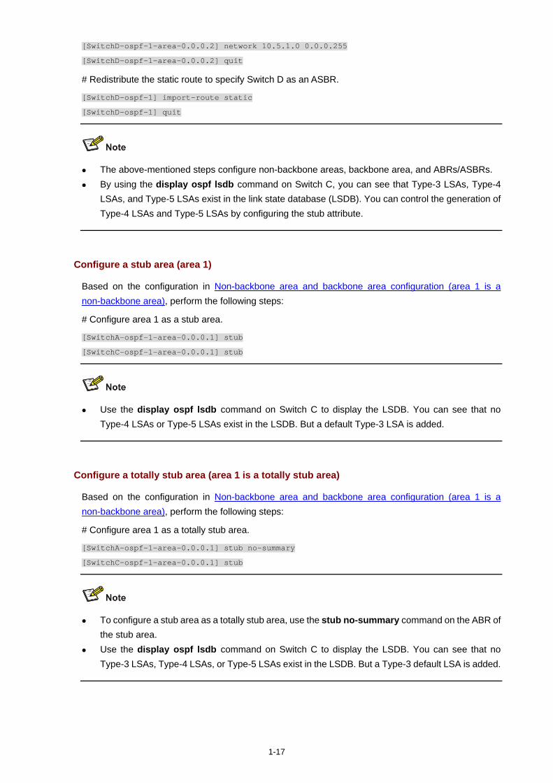
1-17
[SwitchD-ospf-1-area-0.0.0.2] network 10.5.1.0 0.0.0.255
[SwitchD-ospf-1-area-0.0.0.2] quit
# Redistribute the static route to specify Switch D as an ASBR.
[SwitchD-ospf-1] import-route static
[SwitchD-ospf-1] quit
The above-mentioned steps configure non-backbone areas, backbone area, and ABRs/ASBRs. By using the display ospf lsdb command on Switch C, you can see that Type-3 LSAs, Type-4
LSAs, and Type-5 LSAs exist in the link state database (LSDB). You can control the generation of Type-4 LSAs and Type-5 LSAs by configuring the stub attribute.
Configure a stub area (area 1)
Based on the configuration in Non-backbone area and backbone area configuration (area 1 is a non-backbone area), perform the following steps:
# Configure area 1 as a stub area.
[SwitchA-ospf-1-area-0.0.0.1] stub
[SwitchC-ospf-1-area-0.0.0.1] stub
Use the display ospf lsdb command on Switch C to display the LSDB. You can see that no Type-4 LSAs or Type-5 LSAs exist in the LSDB. But a default Type-3 LSA is added.
Configure a totally stub area (area 1 is a totally stub area)
Based on the configuration in Non-backbone area and backbone area configuration (area 1 is a non-backbone area), perform the following steps:
# Configure area 1 as a totally stub area.
[SwitchA-ospf-1-area-0.0.0.1] stub no-summary
[SwitchC-ospf-1-area-0.0.0.1] stub
To configure a stub area as a totally stub area, use the stub no-summary command on the ABR of the stub area.
Use the display ospf lsdb command on Switch C to display the LSDB. You can see that no Type-3 LSAs, Type-4 LSAs, or Type-5 LSAs exist in the LSDB. But a Type-3 default LSA is added.
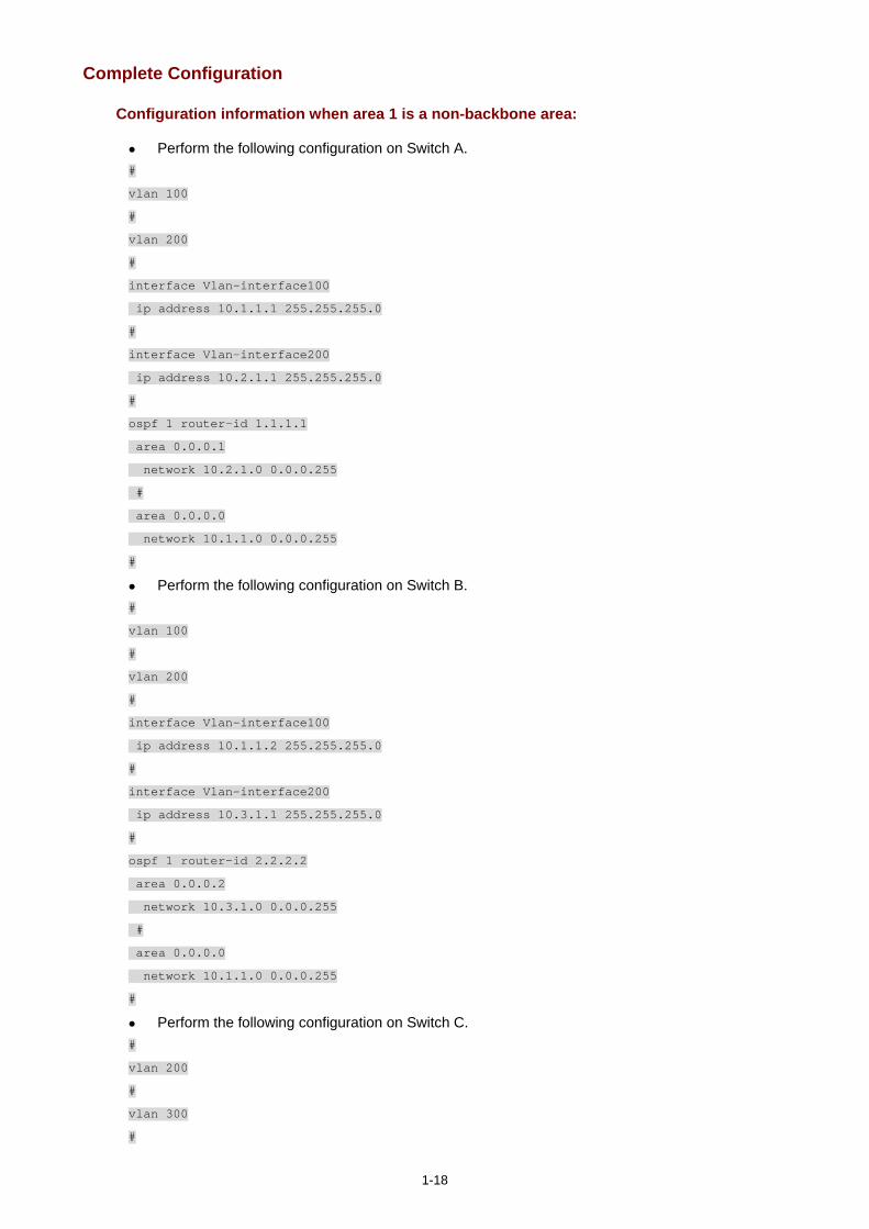
1-18
Complete Configuration
Configuration information when area 1 is a non-backbone area:
Perform the following configuration on Switch A. #
vlan 100
#
vlan 200
#
interface Vlan-interface100
ip address 10.1.1.1 255.255.255.0
#
interface Vlan-interface200
ip address 10.2.1.1 255.255.255.0
#
ospf 1 router-id 1.1.1.1
area 0.0.0.1
network 10.2.1.0 0.0.0.255
#
area 0.0.0.0
network 10.1.1.0 0.0.0.255
#
Perform the following configuration on Switch B. #
vlan 100
#
vlan 200
#
interface Vlan-interface100
ip address 10.1.1.2 255.255.255.0
#
interface Vlan-interface200
ip address 10.3.1.1 255.255.255.0
#
ospf 1 router-id 2.2.2.2
area 0.0.0.2
network 10.3.1.0 0.0.0.255
#
area 0.0.0.0
network 10.1.1.0 0.0.0.255
#
Perform the following configuration on Switch C. #
vlan 200
#
vlan 300
#
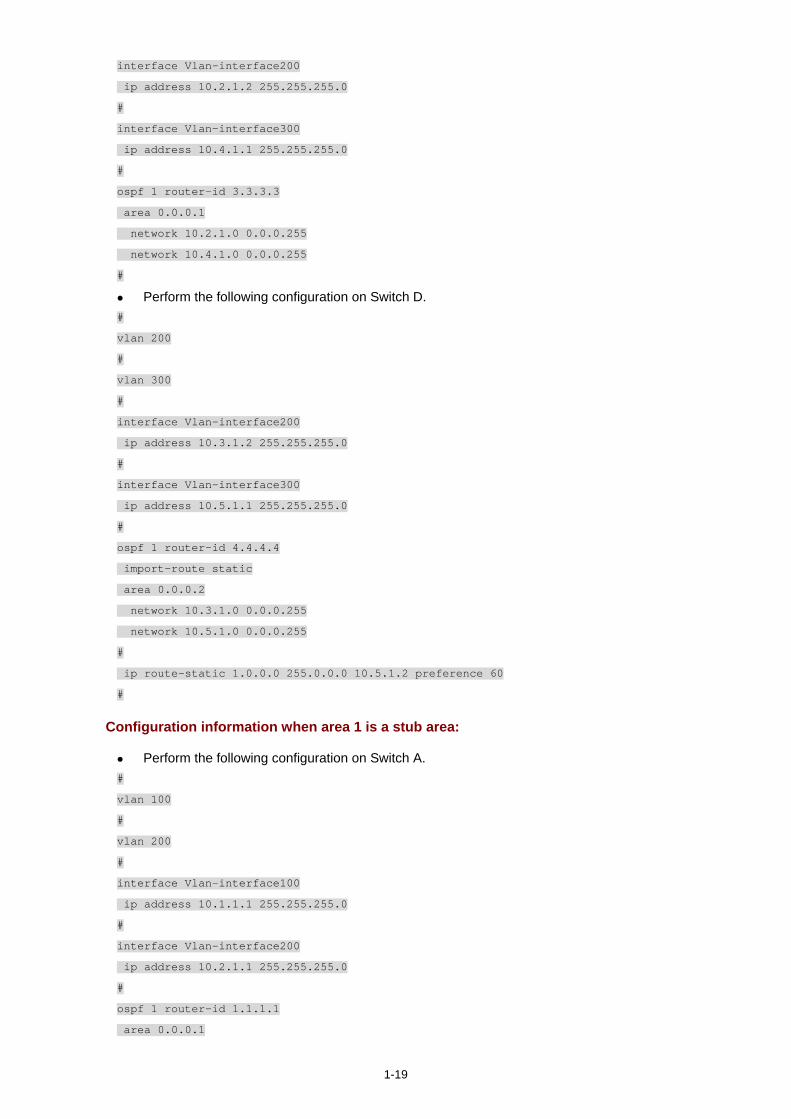
1-19
interface Vlan-interface200
ip address 10.2.1.2 255.255.255.0
#
interface Vlan-interface300
ip address 10.4.1.1 255.255.255.0
#
ospf 1 router-id 3.3.3.3
area 0.0.0.1
network 10.2.1.0 0.0.0.255
network 10.4.1.0 0.0.0.255
#
Perform the following configuration on Switch D. #
vlan 200
#
vlan 300
#
interface Vlan-interface200
ip address 10.3.1.2 255.255.255.0
#
interface Vlan-interface300
ip address 10.5.1.1 255.255.255.0
#
ospf 1 router-id 4.4.4.4
import-route static
area 0.0.0.2
network 10.3.1.0 0.0.0.255
network 10.5.1.0 0.0.0.255
#
ip route-static 1.0.0.0 255.0.0.0 10.5.1.2 preference 60
#
Configuration information when area 1 is a stub area:
Perform the following configuration on Switch A. #
vlan 100
#
vlan 200
#
interface Vlan-interface100
ip address 10.1.1.1 255.255.255.0
#
interface Vlan-interface200
ip address 10.2.1.1 255.255.255.0
#
ospf 1 router-id 1.1.1.1
area 0.0.0.1
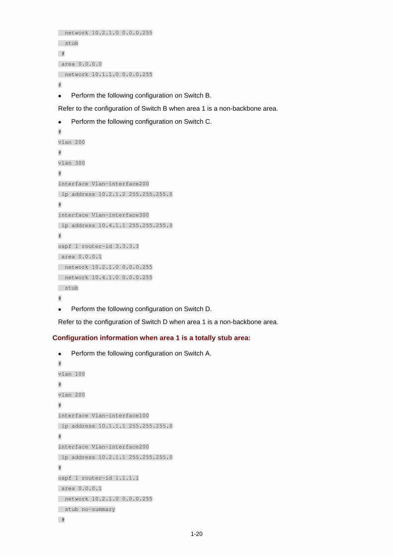
1-20
network 10.2.1.0 0.0.0.255
stub
#
area 0.0.0.0
network 10.1.1.0 0.0.0.255
#
Perform the following configuration on Switch B.
Refer to the configuration of Switch B when area 1 is a non-backbone area.
Perform the following configuration on Switch C. #
vlan 200
#
vlan 300
#
interface Vlan-interface200
ip address 10.2.1.2 255.255.255.0
#
interface Vlan-interface300
ip address 10.4.1.1 255.255.255.0
#
ospf 1 router-id 3.3.3.3
area 0.0.0.1
network 10.2.1.0 0.0.0.255
network 10.4.1.0 0.0.0.255
stub
#
Perform the following configuration on Switch D.
Refer to the configuration of Switch D when area 1 is a non-backbone area.
Configuration information when area 1 is a totally stub area:
Perform the following configuration on Switch A. #
vlan 100
#
vlan 200
#
interface Vlan-interface100
ip address 10.1.1.1 255.255.255.0
#
interface Vlan-interface200
ip address 10.2.1.1 255.255.255.0
#
ospf 1 router-id 1.1.1.1
area 0.0.0.1
network 10.2.1.0 0.0.0.255
stub no-summary
#
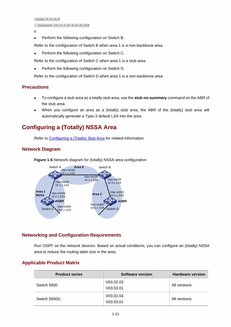
1-21
area 0.0.0.0
network 10.1.1.0 0.0.0.255
#
Perform the following configuration on Switch B.
Refer to the configuration of Switch B when area 1 is a non-backbone area.
Perform the following configuration on Switch C.
Refer to the configuration of Switch C when area 1 is a stub area.
Perform the following configuration on Switch D.
Refer to the configuration of Switch D when area 1 is a non-backbone area.
Precautions
To configure a stub area as a totally stub area, use the stub no-summary command on the ABR of the stub area.
When you configure an area as a (totally) stub area, the ABR of the (totally) stub area will automatically generate a Type-3 default LSA into the area.
Configuring a (Totally) NSSA Area
Refer to Configuring a (Totally) Stub Area for related information.
Network Diagram
Figure 1-6 Network diagram for (totally) NSSA area configuration
Area 0
Area 1NSSA Area 2
Switch C
Vlan-int10010.1.1.2/24
Vlan-int10010.1.1.1/24
Vlan-int30010.4.1.1/24
Vlan-int20010.2.1.2/24
Switch B
Vlan-int20010.3.1.1/24
Vlan-int20010.3.1.2/24
Switch A
Vlan-int20010.2.1.1/24
Vlan-int30010.5.1.1/24 Switch D
ASBRASBR
Networking and Configuration Requirements
Run OSPF on the network devices. Based on actual conditions, you can configure an (totally) NSSA area to reduce the routing table size in the area.
Applicable Product Matrix
Product series Software version Hardware version
Switch 5500 V03.02.03 V03.03.01
All versions
Switch 5500G V03.02.04 V03.03.01
All versions
1-22
Configuration Procedure
Non-backbone area and backbone area configuration (area 1 is a non-backbone area)
Configure Switch A.
# Create VLANs and configure IP addresses for the VLAN interfaces. The configuration procedure is omitted.
# Configure OSPF for area 1.
<SwitchA> system-view
[SwitchA] ospf 1 router-id 1.1.1.1
[SwitchA-ospf-1] area 1
[SwitchA-ospf-1-area-0.0.0.1] network 10.2.1.0 0.0.0.255
# Configure OSPF for the backbone area.
[SwitchA-ospf-1] area 0
[SwitchA-ospf-1-area-0.0.0.0] network 10.1.1.0 0.0.0.255
Configure Switch B (refer to the configuration on Switch A). Configure Switch C.
# Create VLANs and configure IP addresses for the VLAN interfaces. The configuration procedure is omitted.
# Configure a static route of 2.0.0.0/8.
<SwitchC> system-view
[SwitchC] ip route-static 2.0.0.0 8 10.4.1.2
# Configure OSPF for area 1.
[SwitchC] ospf 1 router-id 3.3.3.3
[SwitchC-ospf-1] area 1
[SwitchC-ospf-1-area-0.0.0.1] network 10.2.1.0 0.0.0.255
[SwitchC-ospf-1-area-0.0.0.1] network 10.4.1.0 0.0.0.255
[SwitchC-ospf-1-area-0.0.0.1] quit
# Redistribute the static route to specify Switch C as an ASBR.
[SwitchC-ospf-1] import-route static
[SwitchC-ospf-1] quit
Configure Switch D.
# Create VLANs and configure IP addresses of the VLAN interfaces. The configuration procedure is omitted.
# Configure a static route of 1.0.0.0/8.
<SwitchD> system-view
[SwitchD] ip route-static 1.0.0.0 8 10.5.1.2
# Configure OSPF for area 2.
[SwitchD] ospf 1 router-id 4.4.4.4
[SwitchD-ospf-1] area 2
[SwitchD-ospf-1-area-0.0.0.2] network 10.3.1.0 0.0.0.255
[SwitchD-ospf-1-area-0.0.0.2] network 10.5.1.0 0.0.0.255
1-23
[SwitchD-ospf-1-area-0.0.0.2] quit
# Redistribute the static route to specify Switch D as an ASBR.
[SwitchD-ospf-1] import-route static
[SwitchD-ospf-1] quit
The above-mentioned steps configure non-backbone areas, backbone area, and ABRs/ASBRs. By using the display ospf lsdb command on Switch C, you can see that Type-3 LSAs, Type-4
LSAs, and Type-5 LSAs exist in the link state database (LSDB).
NSSA area configuration 1 (area 1 is an NSSA area)
After this configuration, packets destined for an IP address (in another AS) advertised by the ASBR of the NSSA area will be forwarded by the ASBR, while packets destined for an IP address (in another AS) not advertised by the ASBR will be dropped.
Based on the configuration in Non-backbone area and backbone area configuration (area 1 is a non-backbone area), perform the following steps:
# Configure area 1 as an NSSA area.
[SwitchA-ospf-1-area-0.0.0.1] nssa
[SwitchC-ospf-1-area-0.0.0.1] nssa
The steps above configure an NSSA area. Use the display ospf lsdb command on Switch C to display the LSDB. You can see that no
Type-4 LSAs or Type-5 LSAs exist in the LSDB. But Type-7 LSAs are installed.
NSSA area configuration 2 (area 1 is an NSSA area)
After this configuration, packets from the NSSA area to other ASs are forwarded by the ASBR of the NSSA area.
Based on the configuration in Non-backbone area and backbone area configuration (area 1 is a non-backbone area), perform the following steps:
# Configure a default route.
1-24
[SwitchC] ip route-static 0.0.0.0 0.0.0.0 10.4.1.2
# Configure Area 1 as an NSSA area. Switch C will forward all the packets to other ASs.
[SwitchA-ospf-1-area-0.0.0.1] nssa
[SwitchC-ospf-1-area-0.0.0.1] nssa default-route-advertise
The steps above configure an NSSA area. Use the display ospf lsdb command on Switch C to display the LSDB. You can see that no
Type-4 LSAs or Type-5 LSAs exist in the LSDB. But Type-7 LSAs and a Type-7 default LSA are added.
NSSA area configuration 3 (area 1 is an NSSA area)
After this configuration, packets destined for an IP address (in another AS) advertised by the ASBR of the NSSA area will be forwarded by the ASBR, while packets destined for an IP address (in another AS) not advertised by the ASBR will be forward by the ABR of the area to the ASBR of another area for further forwarding.
Based on the configuration in Non-backbone area and backbone area configuration (area 1 is a non-backbone area), perform the following steps:
# Configure area 1 as an NSSA area.
[SwitchA-ospf-1-area-0.0.0.1] nssa default-route-advertise
[SwitchC-ospf-1-area-0.0.0.1] nssa
The steps above configure an NSSA area. Use the display ospf lsdb command on Switch C to display the LSDB. You can see that no
Type-4 LSAs or Type-5 LSAs exist in the LSDB. But Type-7 LSAs and a Type-7 default LSA are installed.
Totally NSSA area configuration (area 1 is a totally NSSA area)
Based on the configuration in Non-backbone area and backbone area configuration (area 1 is a non-backbone area), perform the following steps:
# Configure area 1 as a totally NSSA area.
[SwitchA-ospf-1-area-0.0.0.1] nssa no-summary
[SwitchC-ospf-1-area-0.0.0.1] nssa
1-25
The steps above configure a totally NSSA area. Use the display ospf lsdb command on Switch C to display the LSDB. You can see that no
Type-3 LSAs, Type-4 LSAs, or Type-5 LSAs exist in the LSDB. But Type-7 LSAs and a default Type-3 LSA are added.
Complete Configuration
In the following example, the ASBR of the NSSA area will forward all the packets destined for other ASs. For the configurations in other cases, refer to Configuration Procedure.
Perform the following configuration on Switch A. #
vlan 100
#
vlan 200
#
interface Vlan-interface100
ip address 10.1.1.1 255.255.255.0
#
interface Vlan-interface200
ip address 10.2.1.1 255.255.255.0
#
ospf 1 router-id 1.1.1.1
area 0.0.0.1
network 10.2.1.0 0.0.0.255
nssa
#
area 0.0.0.0
network 10.1.1.0 0.0.0.255
#
Perform the following configuration on Switch B. #
vlan 100
#
vlan 200
#
interface Vlan-interface100
ip address 10.1.1.2 255.255.255.0
#
interface Vlan-interface200

1-26
ip address 10.3.1.1 255.255.255.0
#
ospf 1 router-id 2.2.2.2
area 0.0.0.2
network 10.3.1.0 0.0.0.255
#
area 0.0.0.0
network 10.1.1.0 0.0.0.255
#
Perform the following configuration on Switch C. #
vlan 200
#
vlan 300
#
interface Vlan-interface200
ip address 10.2.1.2 255.255.255.0
#
interface Vlan-interface300
ip address 10.4.1.1 255.255.255.0
#
ospf 1 router-id 3.3.3.3
import-route static
area 0.0.0.1
network 10.2.1.0 0.0.0.255
network 10.4.1.0 0.0.0.255
nssa default-route-advertise
#
ip route-static 0.0.0.0 0.0.0.0 10.4.1.2 preference 60
ip route-static 2.0.0.0 255.0.0.0 10.4.1.2 preference 60
#
Perform the following configuration on Switch D. #
vlan 200
#
vlan 300
#
interface Vlan-interface200
ip address 10.3.1.2 255.255.255.0
#
interface Vlan-interface300
ip address 10.5.1.1 255.255.255.0
#
ospf 1 router-id 4.4.4.4
import-route static
area 0.0.0.2
network 10.3.1.0 0.0.0.255
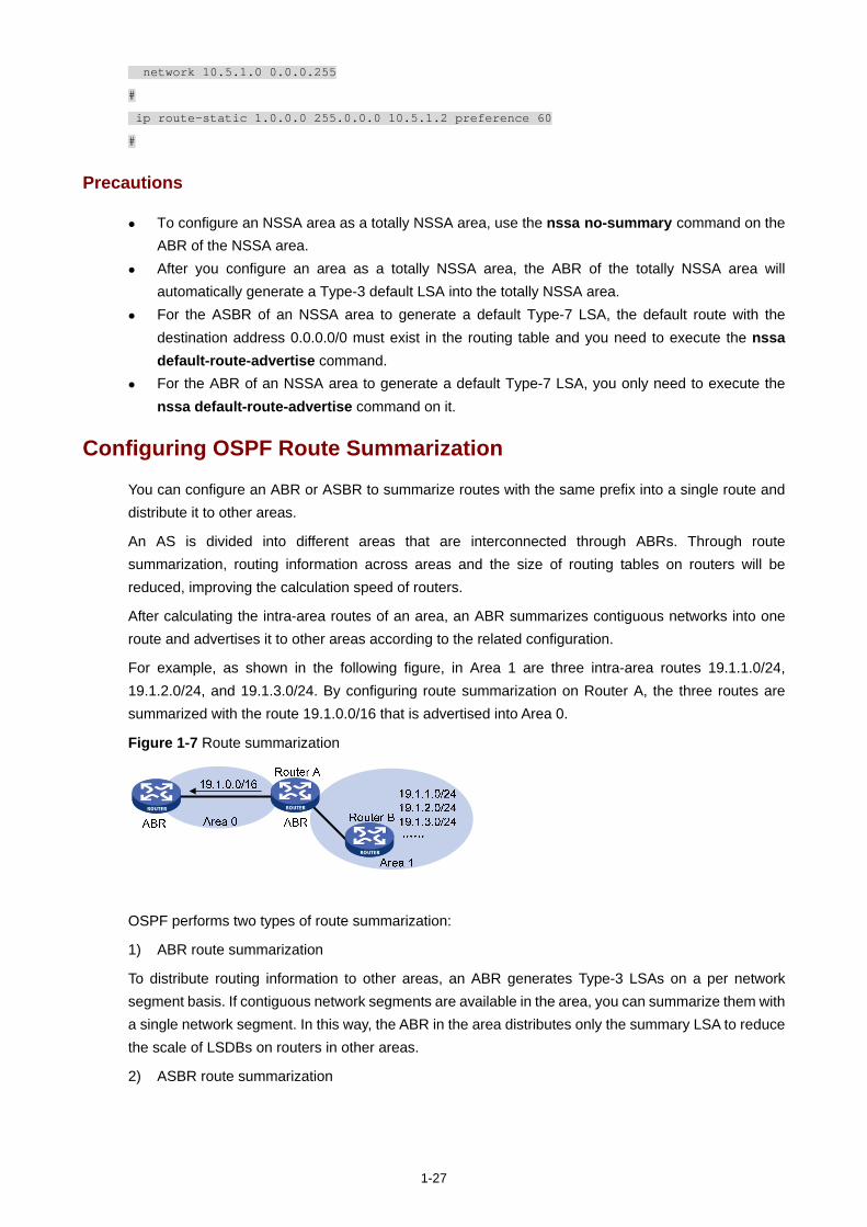
1-27
network 10.5.1.0 0.0.0.255
#
ip route-static 1.0.0.0 255.0.0.0 10.5.1.2 preference 60
#
Precautions
To configure an NSSA area as a totally NSSA area, use the nssa no-summary command on the ABR of the NSSA area.
After you configure an area as a totally NSSA area, the ABR of the totally NSSA area will automatically generate a Type-3 default LSA into the totally NSSA area.
For the ASBR of an NSSA area to generate a default Type-7 LSA, the default route with the destination address 0.0.0.0/0 must exist in the routing table and you need to execute the nssa default-route-advertise command.
For the ABR of an NSSA area to generate a default Type-7 LSA, you only need to execute the nssa default-route-advertise command on it.
Configuring OSPF Route Summarization
You can configure an ABR or ASBR to summarize routes with the same prefix into a single route and distribute it to other areas.
An AS is divided into different areas that are interconnected through ABRs. Through route summarization, routing information across areas and the size of routing tables on routers will be reduced, improving the calculation speed of routers.
After calculating the intra-area routes of an area, an ABR summarizes contiguous networks into one route and advertises it to other areas according to the related configuration.
For example, as shown in the following figure, in Area 1 are three intra-area routes 19.1.1.0/24, 19.1.2.0/24, and 19.1.3.0/24. By configuring route summarization on Router A, the three routes are summarized with the route 19.1.0.0/16 that is advertised into Area 0.
Figure 1-7 Route summarization
OSPF performs two types of route summarization:
1) ABR route summarization
To distribute routing information to other areas, an ABR generates Type-3 LSAs on a per network segment basis. If contiguous network segments are available in the area, you can summarize them with a single network segment. In this way, the ABR in the area distributes only the summary LSA to reduce the scale of LSDBs on routers in other areas.
2) ASBR route summarization
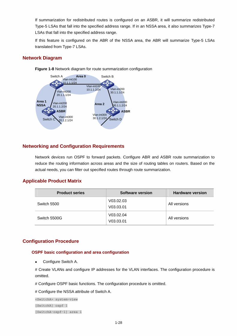
1-28
If summarization for redistributed routes is configured on an ASBR, it will summarize redistributed Type-5 LSAs that fall into the specified address range. If in an NSSA area, it also summarizes Type-7 LSAs that fall into the specified address range.
If this feature is configured on the ABR of the NSSA area, the ABR will summarize Type-5 LSAs translated from Type-7 LSAs.
Network Diagram
Figure 1-8 Network diagram for route summarization configuration
Area 0
Area 1NSSA Area 2
Switch C
Vlan-int10010.1.1.2/24
Vlan-int10010.1.1.1/24
Vlan-int30020.1.2.1/24
Vlan-int20020.1.1.2/24
Switch B
Vlan-int20030.1.1.1/24
Vlan-int20030.1.1.2/24
Switch A
Vlan-int20020.1.1.1/24
Vlan-int30030.1.2.1/24 Switch D
ASBRASBR
Networking and Configuration Requirements
Network devices run OSPF to forward packets. Configure ABR and ASBR route summarization to reduce the routing information across areas and the size of routing tables on routers. Based on the actual needs, you can filter out specified routes through route summarization.
Applicable Product Matrix
Product series Software version Hardware version
Switch 5500 V03.02.03 V03.03.01
All versions
Switch 5500G V03.02.04 V03.03.01
All versions
Configuration Procedure
OSPF basic configuration and area configuration
Configure Switch A.
# Create VLANs and configure IP addresses for the VLAN interfaces. The configuration procedure is omitted.
# Configure OSPF basic functions. The configuration procedure is omitted.
# Configure the NSSA attribute of Switch A.
<SwitchA> system-view
[SwitchA] ospf 1
[SwitchA-ospf-1] area 1
1-29
[SwitchA-ospf-1-area-0.0.0.1] nssa
[SwitchA-ospf-1-area-0.0.0.1] quit
Configure Switch C.
# Create VLANs and configure IP addresses for the VLAN interfaces. The configuration procedure is omitted.
# Configure OSPF basic functions. The configuration procedure is omitted.
# Configure the static routes 2.1.3.0/24, 2.1.4.0/24, 2.1.5.0/24, 2.1.6.0/24, and 2.1.7.0/24.
<SwitchC> system-view
[SwitchC] ip route-static 2.1.3.0 24 20.1.2.2
[SwitchC] ip route-static 2.1.4.0 24 20.1.2.2
[SwitchC] ip route-static 2.1.5.0 24 20.1.2.2
[SwitchC] ip route-static 2.1.6.0 24 20.1.2.2
[SwitchC] ip route-static 2.1.7.0 24 20.1.2.2
# Redistribute the static routes and configure the NSSA attribute of Switch C.
[SwitchC] ospf 1
[SwitchC-ospf-1] import-route static
[SwitchC-ospf-1] area 1
[SwitchC-ospf-1-area-0.0.0.1] nssa
[SwitchC-ospf-1-area-0.0.0.1] quit
Configure Switch B.
# Create VLANs and configure IP addresses for the VLAN interfaces. The configuration procedure is omitted.
# Configure OSPF basic functions. The configuration procedure is omitted.
Configure Switch D.
# Create VLANs and configure IP addresses for the VLAN interfaces. The configuration procedure is omitted.
# Configure OSPF basic functions. The configuration procedure is omitted.
# Configure the static routes 1.1.3.0/24, 1.1.4.0/24, 1.1.5.0/24, 1.1.6.0/24, and 1.1.7.0/24.
<SwitchD> system-view
[SwitchD] ip route-static 1.1.3.0 24 30.1.2.2
[SwitchD] ip route-static 1.1.4.0 24 30.1.2.2
[SwitchD] ip route-static 1.1.5.0 24 30.1.2.2
[SwitchD] ip route-static 1.1.6.0 24 30.1.2.2
[SwitchD] ip route-static 1.1.7.0 24 30.1.2.2
# Redistribute the static routes.
[SwitchD] ospf 1
[SwitchD-ospf-1] import-route static
1-30
ABR route summarization configuration
This configuration is applicable when an ABR needs to summarize the Type-3 LSAs of an area. The following takes the ABR route summarization configuration on Switch B as an example.
Based on OSPF basic configuration and area configuration, perform the following configuration:
# Configure ABR route summarization to summarize the routes 30.1.1.0/24 and 30.1.2.0/24 in area 2 into 30.1.0.0/22.
[SwitchB-ospf-1] area 2
[SwitchB-ospf-1-area-0.0.0.2] abr-summary 30.1.0.0 255.255.252.0
[SwitchB-ospf-1-area-0.0.0.2] quit
ASBR route summarization configuration 1
This configuration is applicable when an ASBR needs to summarize the Type-5 LSAs or Type-7 LSAs. The following takes the ASBR route summarization configuration on Switch D as an example.
Based on OSPF basic configuration and area configuration, perform the following configuration:
# Configure ASBR route summarization to summarize the routes 1.1.4.0/24, 1.1.5.0/24, 1.1.6.0/24, and 1.1.7.0/24 into 1.1.4.0/22 and to prevent 1.1.3.0/24 from being advertised to any other area.
[SwitchD-ospf-1] asbr-summary 1.1.4.0 255.255.252.0
[SwitchD-ospf-1] asbr-summary 1.1.3.0 255.255.255.0 not-advertise
ASBR route summarization configuration 2
This configuration is applicable when the ABR in an NSSA area needs to translate Type-7 LSAs into Type-5 LSAs and summarize the Type-5 LSAs.
Based on OSPF basic configuration and area configuration, perform the following configuration:
# Switch A is the ABR of the NSSA area. Configure ASBR route summarization to summarize the routes 2.1.4.0/24, 2.1.5.0/24, 2.1.6.0/24, and 2.1.7.0/24 into 2.1.4.0/22 and to prevent 2.1.3.0/24 from being advertised.
[SwitchA-ospf-1] asbr-summary 2.1.4.0 255.255.252.0
[SwitchA-ospf-1] asbr-summary 2.1.3.0 255.255.255.0 not-advertise
1-31
Complete Configuration
ABR route summarization configuration
Configure ABR route summarization on Switch B.
Perform the following configuration on Switch A. #
vlan 100
#
vlan 200
#
interface Vlan-interface100
ip address 10.1.1.1 255.255.255.0
#
interface Vlan-interface200
ip address 20.1.1.1 255.255.255.0
#
ospf 1 router-id 1.1.1.1
area 0.0.0.1
network 20.1.1.0 0.0.0.255
nssa
#
area 0.0.0.0
network 10.1.1.0 0.0.0.255
#
Perform the following configuration on Switch B. #
vlan 100
#
vlan 200
#
interface Vlan-interface100
ip address 10.1.1.2 255.255.255.0
#
interface Vlan-interface200
ip address 30.1.1.1 255.255.255.0
#
ospf 1 router-id 2.2.2.2
area 0.0.0.2
network 30.1.1.0 0.0.0.255
abr-summary 30.1.0.0 255.255.252.0 advertise
#
area 0.0.0.0

1-32
network 10.1.1.0 0.0.0.255
#
Perform the following configuration on Switch C. #
vlan 200
#
vlan 300
#
interface Vlan-interface200
ip address 20.1.1.2 255.255.255.0
#
interface Vlan-interface300
ip address 20.1.2.1 255.255.255.0
#
ospf 1 router-id 3.3.3.3
import-route static
area 0.0.0.2
network 20.1.1.0 0.0.0.255
network 20.1.2.0 0.0.0.255
nssa
#
ip route-static 2.1.3.0 255.255.255.0 20.1.2.2 preference 60
ip route-static 2.1.4.0 255.255.255.0 20.1.2.2 preference 60
ip route-static 2.1.5.0 255.255.255.0 20.1.2.2 preference 60
ip route-static 2.1.6.0 255.255.255.0 20.1.2.2 preference 60
ip route-static 2.1.7.0 255.255.255.0 20.1.2.2 preference 60
#
Perform the following configuration on Switch D. #
vlan 200
#
vlan 300
#
interface Vlan-interface200
ip address 30.1.1.2 255.255.255.0
#
interface Vlan-interface300
ip address 30.1.2.1 255.255.255.0
#
ospf 1 router-id 4.4.4.4
import-route static
area 0.0.0.2
network 30.1.1.0 0.0.0.255
network 30.1.2.0 0.0.0.255
#
ip route-static 1.1.3.0 255.255.255.0 30.1.2.2 preference 60
ip route-static 1.1.4.0 255.255.255.0 30.1.2.2 preference 60
1-33
ip route-static 1.1.5.0 255.255.255.0 30.1.2.2 preference 60
ip route-static 1.1.6.0 255.255.255.0 30.1.2.2 preference 60
ip route-static 1.1.7.0 255.255.255.0 30.1.2.2 preference 60
#
ASBR route summarization configuration 1
Configure ASBR route summarization on Switch D.
Configure Switch A. #
vlan 100
#
vlan 200
#
interface Vlan-interface100
ip address 10.1.1.1 255.255.255.0
#
interface Vlan-interface200
ip address 20.1.1.1 255.255.255.0
#
ospf 1 router-id 1.1.1.1
area 0.0.0.1
network 20.1.1.0 0.0.0.255
nssa
#
area 0.0.0.0
network 10.1.1.0 0.0.0.255
#
Configure Switch B. #
vlan 100
#
vlan 200
#
interface Vlan-interface100
ip address 10.1.1.2 255.255.255.0
#
interface Vlan-interface200
ip address 30.1.1.1 255.255.255.0
#
ospf 1 router-id 2.2.2.2
area 0.0.0.2
network 30.1.1.0 0.0.0.255
#

1-34
area 0.0.0.0
network 10.1.1.0 0.0.0.255
#
Configure Switch C. #
vlan 200
#
vlan 300
#
interface Vlan-interface200
ip address 20.1.1.2 255.255.255.0
#
interface Vlan-interface300
ip address 20.1.2.1 255.255.255.0
#
ospf 1 router-id 3.3.3.3
import-route static
area 0.0.0.2
network 20.1.1.0 0.0.0.255
network 20.1.2.0 0.0.0.255
nssa
#
ip route-static 2.1.3.0 255.255.255.0 20.1.2.2 preference 60
ip route-static 2.1.4.0 255.255.255.0 20.1.2.2 preference 60
ip route-static 2.1.5.0 255.255.255.0 20.1.2.2 preference 60
ip route-static 2.1.6.0 255.255.255.0 20.1.2.2 preference 60
ip route-static 2.1.7.0 255.255.255.0 20.1.2.2 preference 60
#
Configure Switch D. #
vlan 200
#
vlan 300
#
interface Vlan-interface200
ip address 30.1.1.2 255.255.255.0
#
interface Vlan-interface300
ip address 30.1.2.1 255.255.255.0
#
ospf 1 router-id 4.4.4.4
asbr-summary 1.1.4.0 255.255.252.0
asbr-summary 1.1.3.0 255.255.255.0 not-advertise
import-route static
area 0.0.0.2
network 30.1.1.0 0.0.0.255
network 30.1.2.0 0.0.0.255
1-35
#
ip route-static 1.1.3.0 255.255.255.0 30.1.2.2 preference 60
ip route-static 1.1.4.0 255.255.255.0 30.1.2.2 preference 60
ip route-static 1.1.5.0 255.255.255.0 30.1.2.2 preference 60
ip route-static 1.1.6.0 255.255.255.0 30.1.2.2 preference 60
ip route-static 1.1.7.0 255.255.255.0 30.1.2.2 preference 60
#
ASBR route summarization configuration 2
Configure ASBR route summarization on Switch A to summarize the Type-5 LSAs translated from Type-7 LSAs.
Configure Switch A. #
vlan 100
#
vlan 200
#
interface Vlan-interface100
ip address 10.1.1.1 255.255.255.0
#
interface Vlan-interface200
ip address 20.1.1.1 255.255.255.0
#
ospf 1 router-id 1.1.1.1
asbr-summary 2.1.4.0 255.255.252.0
asbr-summary 2.1.3.0 255.255.255.0 not-advertise
area 0.0.0.1
network 20.1.1.0 0.0.0.255
nssa
#
area 0.0.0.0
network 10.1.1.0 0.0.0.255
#
Configure Switch B. #
vlan 100
#
vlan 200
#
interface Vlan-interface100
ip address 10.1.1.2 255.255.255.0
#
interface Vlan-interface200

1-36
ip address 30.1.1.1 255.255.255.0
#
ospf 1 router-id 2.2.2.2
area 0.0.0.2
network 30.1.1.0 0.0.0.255
#
area 0.0.0.0
network 10.1.1.0 0.0.0.255
#
Configure Switch C. #
vlan 200
#
vlan 300
#
interface Vlan-interface200
ip address 20.1.1.2 255.255.255.0
#
interface Vlan-interface300
ip address 20.1.2.1 255.255.255.0
#
ospf 1 router-id 3.3.3.3
import-route static
area 0.0.0.2
network 20.1.1.0 0.0.0.255
network 20.1.2.0 0.0.0.255
nssa
#
ip route-static 2.1.3.0 255.255.255.0 20.1.2.2 preference 60
ip route-static 2.1.4.0 255.255.255.0 20.1.2.2 preference 60
ip route-static 2.1.5.0 255.255.255.0 20.1.2.2 preference 60
ip route-static 2.1.6.0 255.255.255.0 20.1.2.2 preference 60
ip route-static 2.1.7.0 255.255.255.0 20.1.2.2 preference 60
#
Configure Switch D. #
vlan 200
#
vlan 300
#
interface Vlan-interface200
ip address 30.1.1.2 255.255.255.0
#
interface Vlan-interface300
ip address 30.1.2.1 255.255.255.0
#
ospf 1 router-id 4.4.4.4
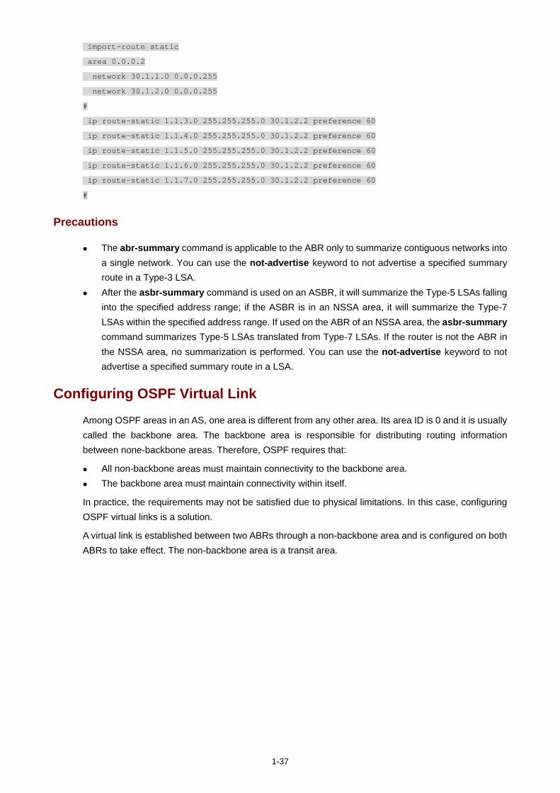
1-37
import-route static
area 0.0.0.2
network 30.1.1.0 0.0.0.255
network 30.1.2.0 0.0.0.255
#
ip route-static 1.1.3.0 255.255.255.0 30.1.2.2 preference 60
ip route-static 1.1.4.0 255.255.255.0 30.1.2.2 preference 60
ip route-static 1.1.5.0 255.255.255.0 30.1.2.2 preference 60
ip route-static 1.1.6.0 255.255.255.0 30.1.2.2 preference 60
ip route-static 1.1.7.0 255.255.255.0 30.1.2.2 preference 60
#
Precautions
The abr-summary command is applicable to the ABR only to summarize contiguous networks into a single network. You can use the not-advertise keyword to not advertise a specified summary route in a Type-3 LSA.
After the asbr-summary command is used on an ASBR, it will summarize the Type-5 LSAs falling into the specified address range; if the ASBR is in an NSSA area, it will summarize the Type-7 LSAs within the specified address range. If used on the ABR of an NSSA area, the asbr-summary command summarizes Type-5 LSAs translated from Type-7 LSAs. If the router is not the ABR in the NSSA area, no summarization is performed. You can use the not-advertise keyword to not advertise a specified summary route in a LSA.
Configuring OSPF Virtual Link
Among OSPF areas in an AS, one area is different from any other area. Its area ID is 0 and it is usually called the backbone area. The backbone area is responsible for distributing routing information between none-backbone areas. Therefore, OSPF requires that:
All non-backbone areas must maintain connectivity to the backbone area. The backbone area must maintain connectivity within itself.
In practice, the requirements may not be satisfied due to physical limitations. In this case, configuring OSPF virtual links is a solution.
A virtual link is established between two ABRs through a non-backbone area and is configured on both ABRs to take effect. The non-backbone area is a transit area.
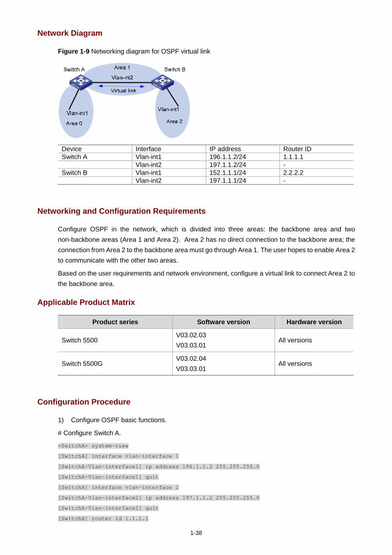
1-38
Network Diagram
Figure 1-9 Networking diagram for OSPF virtual link
Device Interface IP address Router ID Switch A Vlan-int1 196.1.1.2/24 1.1.1.1 Vlan-int2 197.1.1.2/24 - Switch B Vlan-int1 152.1.1.1/24 2.2.2.2 Vlan-int2 197.1.1.1/24 -
Networking and Configuration Requirements
Configure OSPF in the network, which is divided into three areas: the backbone area and two non-backbone areas (Area 1 and Area 2). Area 2 has no direct connection to the backbone area; the connection from Area 2 to the backbone area must go through Area 1. The user hopes to enable Area 2 to communicate with the other two areas.
Based on the user requirements and network environment, configure a virtual link to connect Area 2 to the backbone area.
Applicable Product Matrix
Product series Software version Hardware version
Switch 5500 V03.02.03 V03.03.01
All versions
Switch 5500G V03.02.04 V03.03.01
All versions
Configuration Procedure
1) Configure OSPF basic functions.
# Configure Switch A.
<SwitchA> system-view
[SwitchA] interface vlan-interface 1
[SwitchA-Vlan-interface1] ip address 196.1.1.2 255.255.255.0
[SwitchA-Vlan-interface1] quit
[SwitchA] interface vlan-interface 2
[SwitchA-Vlan-interface2] ip address 197.1.1.2 255.255.255.0
[SwitchA-Vlan-interface2] quit
[SwitchA] router id 1.1.1.1

1-39
[SwitchA] ospf
[SwitchA-ospf-1] area 0
[SwitchA-ospf-1-area-0.0.0.0] network 196.1.1.0 0.0.0.255
[SwitchA-ospf-1-area-0.0.0.0] quit
[SwitchA-ospf-1] area 1
[SwitchA-ospf-1-area-0.0.0.1] network 197.1.1.0 0.0.0.255
[SwitchA-ospf-1-area-0.0.0.1] quit
# Configure Switch B.
<SwitchB> system-view
[SwitchB] interface Vlan-interface 1
[SwitchB-Vlan-interface1] ip address 152.1.1.1 255.255.255.0
[SwitchB-Vlan-interface1] quit
[SwitchB] interface Vlan-interface 2
[SwitchB-Vlan-interface2] ip address 197.1.1.1 255.255.255.0
[SwitchB-Vlan-interface2] quit
[SwitchB] router id 2.2.2.2
[SwitchB] ospf
[SwitchB-ospf-1] area 1
[SwitchB-ospf-1-area-0.0.0.1] network 197.1.1.0 0.0.0.255
[SwitchB-ospf-1-area-0.0.0.1] quit
[SwitchB-ospf-1] area 2
[SwitchB-ospf-1-area-0.0.0.2] network 152.1.1.0 0.0.0.255
[SwitchB-ospf-1-area-0.0.0.2] quit
2) Configure a virtual link.
# Configure Switch A.
[SwitchA-ospf-1] area 1
[SwitchA-ospf-1-area-0.0.0.1] vlink-peer 2.2.2.2
[SwitchA-ospf-1-area-0.0.0.1] quit
[SwitchA-ospf-1] quit
# Configure Switch B.
[SwitchB-ospf-1] area 1
[SwitchB-ospf-1-area-0.0.0.1] vlink-peer 1.1.1.1
[SwitchB-ospf-1-area-0.0.0.1] quit
Complete Configuration
Perform the following configuration on Switch A. #
router id 1.1.1.1
#
vlan 1
#
vlan 2
#
interface Vlan-interface1
ip address 196.1.1.2 255.255.255.0
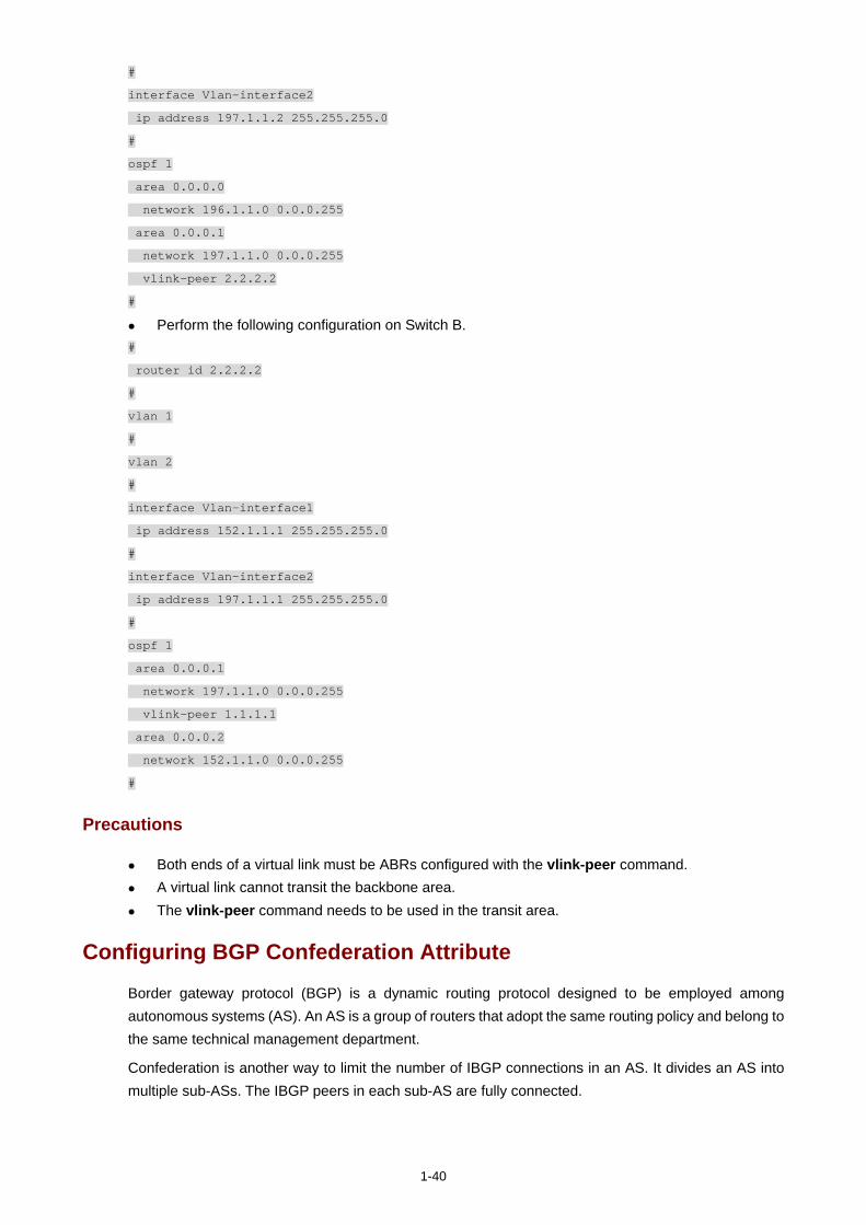
1-40
#
interface Vlan-interface2
ip address 197.1.1.2 255.255.255.0
#
ospf 1
area 0.0.0.0
network 196.1.1.0 0.0.0.255
area 0.0.0.1
network 197.1.1.0 0.0.0.255
vlink-peer 2.2.2.2
#
Perform the following configuration on Switch B. #
router id 2.2.2.2
#
vlan 1
#
vlan 2
#
interface Vlan-interface1
ip address 152.1.1.1 255.255.255.0
#
interface Vlan-interface2
ip address 197.1.1.1 255.255.255.0
#
ospf 1
area 0.0.0.1
network 197.1.1.0 0.0.0.255
vlink-peer 1.1.1.1
area 0.0.0.2
network 152.1.1.0 0.0.0.255
#
Precautions
Both ends of a virtual link must be ABRs configured with the vlink-peer command. A virtual link cannot transit the backbone area. The vlink-peer command needs to be used in the transit area.
Configuring BGP Confederation Attribute
Border gateway protocol (BGP) is a dynamic routing protocol designed to be employed among autonomous systems (AS). An AS is a group of routers that adopt the same routing policy and belong to the same technical management department.
Confederation is another way to limit the number of IBGP connections in an AS. It divides an AS into multiple sub-ASs. The IBGP peers in each sub-AS are fully connected.
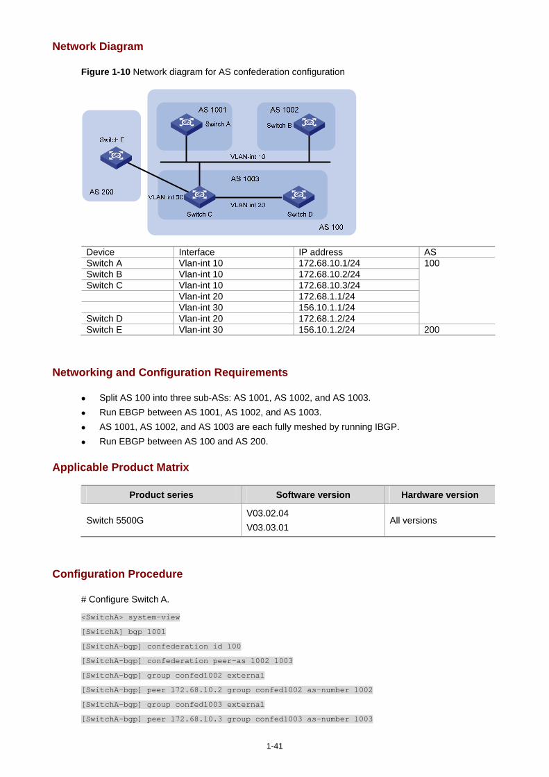
1-41
Network Diagram
Figure 1-10 Network diagram for AS confederation configuration
Device Interface IP address AS Switch A Vlan-int 10 172.68.10.1/24 Switch B Vlan-int 10 172.68.10.2/24 Switch C Vlan-int 10 172.68.10.3/24 Vlan-int 20 172.68.1.1/24 Vlan-int 30 156.10.1.1/24 Switch D Vlan-int 20 172.68.1.2/24
100
Switch E Vlan-int 30 156.10.1.2/24 200
Networking and Configuration Requirements
Split AS 100 into three sub-ASs: AS 1001, AS 1002, and AS 1003. Run EBGP between AS 1001, AS 1002, and AS 1003. AS 1001, AS 1002, and AS 1003 are each fully meshed by running IBGP. Run EBGP between AS 100 and AS 200.
Applicable Product Matrix
Product series Software version Hardware version
Switch 5500G V03.02.04 V03.03.01
All versions
Configuration Procedure
# Configure Switch A.
<SwitchA> system-view
[SwitchA] bgp 1001
[SwitchA-bgp] confederation id 100
[SwitchA-bgp] confederation peer-as 1002 1003
[SwitchA-bgp] group confed1002 external
[SwitchA-bgp] peer 172.68.10.2 group confed1002 as-number 1002
[SwitchA-bgp] group confed1003 external
[SwitchA-bgp] peer 172.68.10.3 group confed1003 as-number 1003
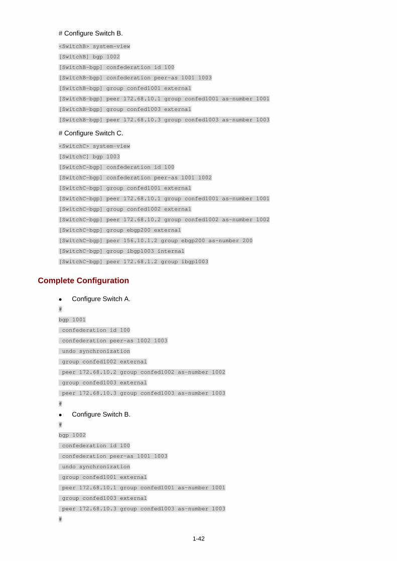
1-42
# Configure Switch B.
<SwitchB> system-view
[SwitchB] bgp 1002
[SwitchB-bgp] confederation id 100
[SwitchB-bgp] confederation peer-as 1001 1003
[SwitchB-bgp] group confed1001 external
[SwitchB-bgp] peer 172.68.10.1 group confed1001 as-number 1001
[SwitchB-bgp] group confed1003 external
[SwitchB-bgp] peer 172.68.10.3 group confed1003 as-number 1003
# Configure Switch C.
<SwitchC> system-view
[SwitchC] bgp 1003
[SwitchC-bgp] confederation id 100
[SwitchC-bgp] confederation peer-as 1001 1002
[SwitchC-bgp] group confed1001 external
[SwitchC-bgp] peer 172.68.10.1 group confed1001 as-number 1001
[SwitchC-bgp] group confed1002 external
[SwitchC-bgp] peer 172.68.10.2 group confed1002 as-number 1002
[SwitchC-bgp] group ebgp200 external
[SwitchC-bgp] peer 156.10.1.2 group ebgp200 as-number 200
[SwitchC-bgp] group ibgp1003 internal
[SwitchC-bgp] peer 172.68.1.2 group ibgp1003
Complete Configuration
Configure Switch A. #
bgp 1001
confederation id 100
confederation peer-as 1002 1003
undo synchronization
group confed1002 external
peer 172.68.10.2 group confed1002 as-number 1002
group confed1003 external
peer 172.68.10.3 group confed1003 as-number 1003
#
Configure Switch B. #
bgp 1002
confederation id 100
confederation peer-as 1001 1003
undo synchronization
group confed1001 external
peer 172.68.10.1 group confed1001 as-number 1001
group confed1003 external
peer 172.68.10.3 group confed1003 as-number 1003
#
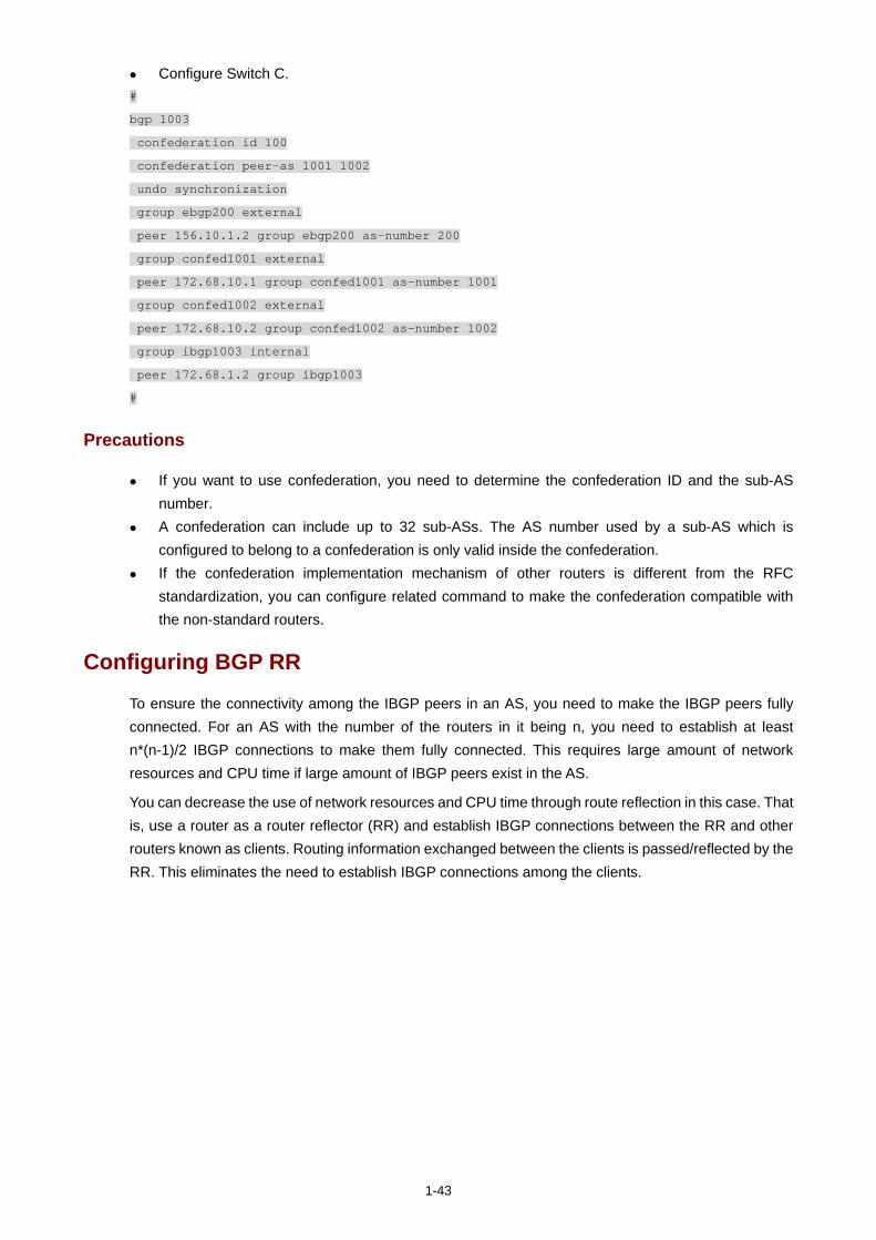
1-43
Configure Switch C. #
bgp 1003
confederation id 100
confederation peer-as 1001 1002
undo synchronization
group ebgp200 external
peer 156.10.1.2 group ebgp200 as-number 200
group confed1001 external
peer 172.68.10.1 group confed1001 as-number 1001
group confed1002 external
peer 172.68.10.2 group confed1002 as-number 1002
group ibgp1003 internal
peer 172.68.1.2 group ibgp1003
#
Precautions
If you want to use confederation, you need to determine the confederation ID and the sub-AS number.
A confederation can include up to 32 sub-ASs. The AS number used by a sub-AS which is configured to belong to a confederation is only valid inside the confederation.
If the confederation implementation mechanism of other routers is different from the RFC standardization, you can configure related command to make the confederation compatible with the non-standard routers.
Configuring BGP RR
To ensure the connectivity among the IBGP peers in an AS, you need to make the IBGP peers fully connected. For an AS with the number of the routers in it being n, you need to establish at least n*(n-1)/2 IBGP connections to make them fully connected. This requires large amount of network resources and CPU time if large amount of IBGP peers exist in the AS.
You can decrease the use of network resources and CPU time through route reflection in this case. That is, use a router as a router reflector (RR) and establish IBGP connections between the RR and other routers known as clients. Routing information exchanged between the clients is passed/reflected by the RR. This eliminates the need to establish IBGP connections among the clients.
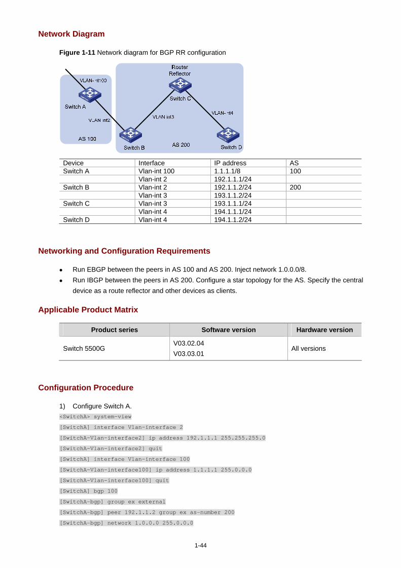
1-44
Network Diagram
Figure 1-11 Network diagram for BGP RR configuration
Device Interface IP address AS Switch A Vlan-int 100 1.1.1.1/8 100 Vlan-int 2 192.1.1.1/24 Switch B Vlan-int 2 192.1.1.2/24 200 Vlan-int 3 193.1.1.2/24 Switch C Vlan-int 3 193.1.1.1/24 Vlan-int 4 194.1.1.1/24 Switch D Vlan-int 4 194.1.1.2/24
Networking and Configuration Requirements
Run EBGP between the peers in AS 100 and AS 200. Inject network 1.0.0.0/8. Run IBGP between the peers in AS 200. Configure a star topology for the AS. Specify the central
device as a route reflector and other devices as clients.
Applicable Product Matrix
Product series Software version Hardware version
Switch 5500G V03.02.04 V03.03.01
All versions
Configuration Procedure
1) Configure Switch A. <SwitchA> system-view
[SwitchA] interface Vlan-interface 2
[SwitchA-Vlan-interface2] ip address 192.1.1.1 255.255.255.0
[SwitchA-Vlan-interface2] quit
[SwitchA] interface Vlan-interface 100
[SwitchA-Vlan-interface100] ip address 1.1.1.1 255.0.0.0
[SwitchA-Vlan-interface100] quit
[SwitchA] bgp 100
[SwitchA-bgp] group ex external
[SwitchA-bgp] peer 192.1.1.2 group ex as-number 200
[SwitchA-bgp] network 1.0.0.0 255.0.0.0
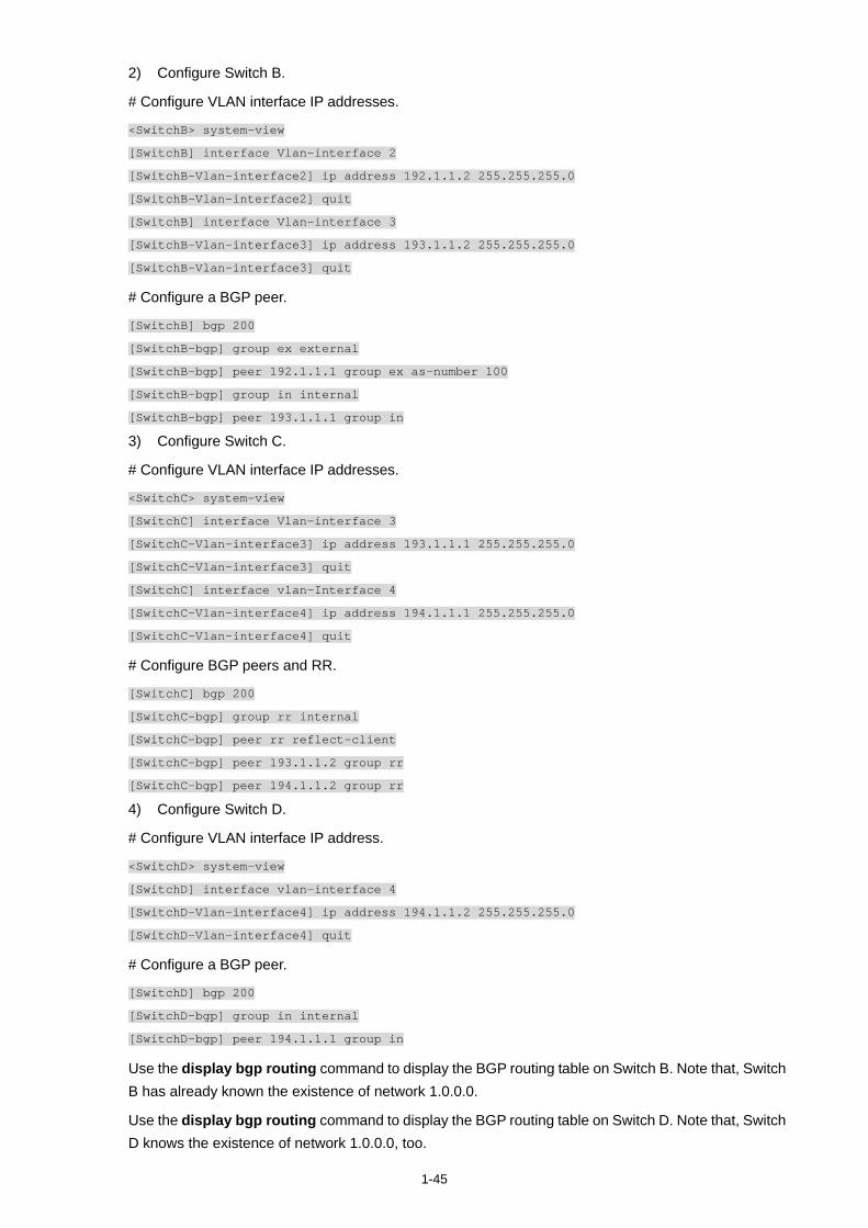
1-45
2) Configure Switch B.
# Configure VLAN interface IP addresses.
<SwitchB> system-view
[SwitchB] interface Vlan-interface 2
[SwitchB-Vlan-interface2] ip address 192.1.1.2 255.255.255.0
[SwitchB-Vlan-interface2] quit
[SwitchB] interface Vlan-interface 3
[SwitchB-Vlan-interface3] ip address 193.1.1.2 255.255.255.0
[SwitchB-Vlan-interface3] quit
# Configure a BGP peer.
[SwitchB] bgp 200
[SwitchB-bgp] group ex external
[SwitchB-bgp] peer 192.1.1.1 group ex as-number 100
[SwitchB-bgp] group in internal
[SwitchB-bgp] peer 193.1.1.1 group in
3) Configure Switch C.
# Configure VLAN interface IP addresses.
<SwitchC> system-view
[SwitchC] interface Vlan-interface 3
[SwitchC-Vlan-interface3] ip address 193.1.1.1 255.255.255.0
[SwitchC-Vlan-interface3] quit
[SwitchC] interface vlan-Interface 4
[SwitchC-Vlan-interface4] ip address 194.1.1.1 255.255.255.0
[SwitchC-Vlan-interface4] quit
# Configure BGP peers and RR.
[SwitchC] bgp 200
[SwitchC-bgp] group rr internal
[SwitchC-bgp] peer rr reflect-client
[SwitchC-bgp] peer 193.1.1.2 group rr
[SwitchC-bgp] peer 194.1.1.2 group rr
4) Configure Switch D.
# Configure VLAN interface IP address.
<SwitchD> system-view
[SwitchD] interface vlan-interface 4
[SwitchD-Vlan-interface4] ip address 194.1.1.2 255.255.255.0
[SwitchD-Vlan-interface4] quit
# Configure a BGP peer.
[SwitchD] bgp 200
[SwitchD-bgp] group in internal
[SwitchD-bgp] peer 194.1.1.1 group in
Use the display bgp routing command to display the BGP routing table on Switch B. Note that, Switch B has already known the existence of network 1.0.0.0.
Use the display bgp routing command to display the BGP routing table on Switch D. Note that, Switch D knows the existence of network 1.0.0.0, too.
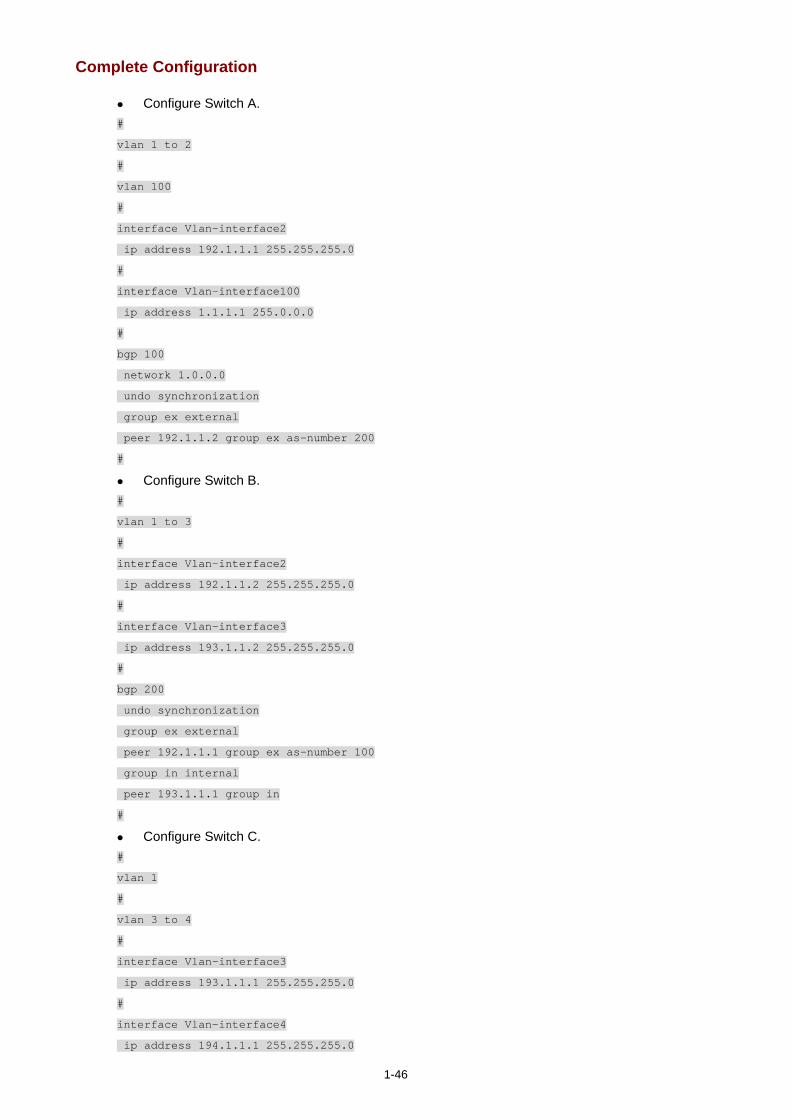
1-46
Complete Configuration
Configure Switch A. #
vlan 1 to 2
#
vlan 100
#
interface Vlan-interface2
ip address 192.1.1.1 255.255.255.0
#
interface Vlan-interface100
ip address 1.1.1.1 255.0.0.0
#
bgp 100
network 1.0.0.0
undo synchronization
group ex external
peer 192.1.1.2 group ex as-number 200
#
Configure Switch B. #
vlan 1 to 3
#
interface Vlan-interface2
ip address 192.1.1.2 255.255.255.0
#
interface Vlan-interface3
ip address 193.1.1.2 255.255.255.0
#
bgp 200
undo synchronization
group ex external
peer 192.1.1.1 group ex as-number 100
group in internal
peer 193.1.1.1 group in
#
Configure Switch C. #
vlan 1
#
vlan 3 to 4
#
interface Vlan-interface3
ip address 193.1.1.1 255.255.255.0
#
interface Vlan-interface4
ip address 194.1.1.1 255.255.255.0

1-47
#
bgp 200
undo synchronization
group rr internal
peer rr reflect-client
peer 193.1.1.2 group rr
peer 194.1.1.2 group rr
#
Configure Switch D. #
vlan 1
#
vlan 4
#
interface Vlan-interface4
ip address 194.1.1.2 255.255.255.0
#
bgp 200
undo synchronization
group in internal
peer 194.1.1.1 group in
#
Precautions
Note that a BGP router which is neither the RR nor a client is called a non-client. Non-clients and the RR must be fully connected.
Normally, full connection is not required between an RR and a client. A route is reflected by an RR from a client to another client. If an RR and a client are fully connected, you can disable the reflection between clients to reduce the cost.
Normally, there is only one RR in a cluster. In this case, the router ID of the RR is used to identify the cluster. Configuring multiple RRs can improve the network stability. If there are multiple RRs in a cluster, use related command to configure the same cluster ID for them to avoid routing loopback.
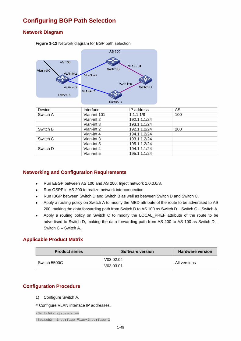
1-48
Configuring BGP Path Selection
Network Diagram
Figure 1-12 Network diagram for BGP path selection
Device Interface IP address AS Switch A Vlan-int 101 1.1.1.1/8 100 Vlan-int 2 192.1.1.1/24 Vlan-int 3 193.1.1.1/24 Switch B Vlan-int 2 192.1.1.2/24 200 Vlan-int 4 194.1.1.2/24 Switch C Vlan-int 3 193.1.1.2/24 Vlan-int 5 195.1.1.2/24 Switch D Vlan-int 4 194.1.1.1/24 Vlan-int 5 195.1.1.1/24
Networking and Configuration Requirements
Run EBGP between AS 100 and AS 200. Inject network 1.0.0.0/8. Run OSPF in AS 200 to realize network interconnection. Run IBGP between Switch D and Switch B as well as between Switch D and Switch C. Apply a routing policy on Switch A to modify the MED attribute of the route to be advertised to AS
200, making the data forwarding path from Switch D to AS 100 as Switch D – Switch C – Switch A. Apply a routing policy on Switch C to modify the LOCAL_PREF attribute of the route to be
advertised to Switch D, making the data forwarding path from AS 200 to AS 100 as Switch D – Switch C – Switch A.
Applicable Product Matrix
Product series Software version Hardware version
Switch 5500G V03.02.04 V03.03.01
All versions
Configuration Procedure
1) Configure Switch A.
# Configure VLAN interface IP addresses.
<SwitchA> system-view
[SwitchA] interface Vlan-interface 2

1-49
[SwitchA-Vlan-interface2] ip address 192.1.1.1 255.255.255.0
[SwitchA-Vlan-interface2] quit
[SwitchA] interface Vlan-interface 3
[SwitchA-Vlan-interface3] ip address 193.1.1.1 255.255.255.0
[SwitchA-Vlan-interface3] quit
# Enable BGP.
[SwitchA] bgp 100
# Inject network 1.0.0.0/8.
[SwitchA-bgp] network 1.0.0.0
# Configure BGP peers.
[SwitchA-bgp] group ex192 external
[SwitchA-bgp] peer 192.1.1.2 group ex192 as-number 200
[SwitchA-bgp] group ex193 external
[SwitchA-bgp] peer 193.1.1.2 group ex193 as-number 200
[SwitchA-bgp] quit
# Define ACL 2000 to permit the route 1.0.0.0/8.
[SwitchA] acl number 2000
[SwitchA-acl-basic-2000] rule permit source 1.0.0.0 0.255.255.255
[SwitchA-acl-basic-2000] rule deny source any
[SwitchA-acl-basic-2000] quit
# Create a routing policy named apply_med_50, and specify node 10 with the permit matching mode for the routing policy. Set the MED value of the route matching ACL 2000 to 50.
[SwitchA] route-policy apply_med_50 permit node 10
[SwitchA-route-policy] if-match acl 2000
[SwitchA-route-policy] apply cost 50
[SwitchA-route-policy] quit
# Create a routing policy named apply_med_100, and specify node 10 with the permit matching mode for the routing policy. Set the MED value of the route matching ACL 2000 to 100.
[SwitchA] route-policy apply_med_100 permit node 10
[SwitchA-route-policy] if-match acl 2000
[SwitchA-route-policy] apply cost 100
[SwitchA-route-policy] quit
# Apply the routing policy apply_med_50 to the routing updates destined for peer group ex193 (the peer 193.1.1.2) and apply_med_100 to the routing updates destined for peer group ex192 (the peer 192.1.1.2).
[SwitchA] bgp 100
[SwitchA-bgp] peer ex193 route-policy apply_med_50 export
[SwitchA-bgp] peer ex192 route-policy apply_med_100 export
2) Configure Switch B.
# Configure VLAN interface IP addresses.
<SwitchB> system-view
[SwitchB] interface vlan 2
[SwitchB-Vlan-interface2] ip address 192.1.1.2 255.255.255.0
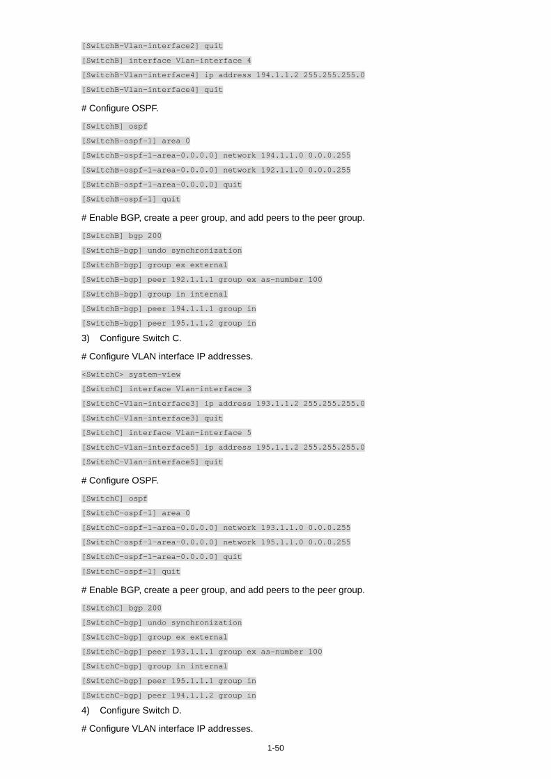
1-50
[SwitchB-Vlan-interface2] quit
[SwitchB] interface Vlan-interface 4
[SwitchB-Vlan-interface4] ip address 194.1.1.2 255.255.255.0
[SwitchB-Vlan-interface4] quit
# Configure OSPF.
[SwitchB] ospf
[SwitchB-ospf-1] area 0
[SwitchB-ospf-1-area-0.0.0.0] network 194.1.1.0 0.0.0.255
[SwitchB-ospf-1-area-0.0.0.0] network 192.1.1.0 0.0.0.255
[SwitchB-ospf-1-area-0.0.0.0] quit
[SwitchB-ospf-1] quit
# Enable BGP, create a peer group, and add peers to the peer group.
[SwitchB] bgp 200
[SwitchB-bgp] undo synchronization
[SwitchB-bgp] group ex external
[SwitchB-bgp] peer 192.1.1.1 group ex as-number 100
[SwitchB-bgp] group in internal
[SwitchB-bgp] peer 194.1.1.1 group in
[SwitchB-bgp] peer 195.1.1.2 group in
3) Configure Switch C.
# Configure VLAN interface IP addresses.
<SwitchC> system-view
[SwitchC] interface Vlan-interface 3
[SwitchC-Vlan-interface3] ip address 193.1.1.2 255.255.255.0
[SwitchC-Vlan-interface3] quit
[SwitchC] interface Vlan-interface 5
[SwitchC-Vlan-interface5] ip address 195.1.1.2 255.255.255.0
[SwitchC-Vlan-interface5] quit
# Configure OSPF.
[SwitchC] ospf
[SwitchC-ospf-1] area 0
[SwitchC-ospf-1-area-0.0.0.0] network 193.1.1.0 0.0.0.255
[SwitchC-ospf-1-area-0.0.0.0] network 195.1.1.0 0.0.0.255
[SwitchC-ospf-1-area-0.0.0.0] quit
[SwitchC-ospf-1] quit
# Enable BGP, create a peer group, and add peers to the peer group.
[SwitchC] bgp 200
[SwitchC-bgp] undo synchronization
[SwitchC-bgp] group ex external
[SwitchC-bgp] peer 193.1.1.1 group ex as-number 100
[SwitchC-bgp] group in internal
[SwitchC-bgp] peer 195.1.1.1 group in
[SwitchC-bgp] peer 194.1.1.2 group in
4) Configure Switch D.
# Configure VLAN interface IP addresses.
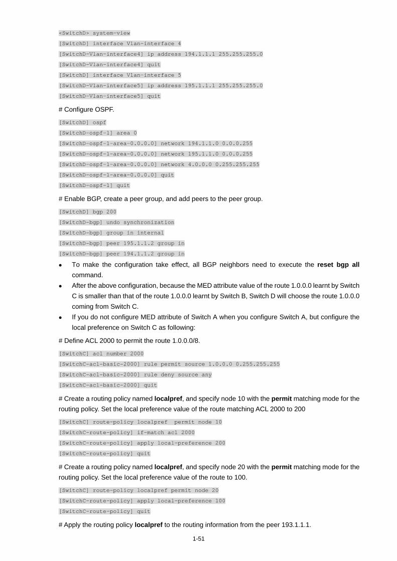
1-51
<SwitchD> system-view
[SwitchD] interface Vlan-interface 4
[SwitchD-Vlan-interface4] ip address 194.1.1.1 255.255.255.0
[SwitchD-Vlan-interface4] quit
[SwitchD] interface Vlan-interface 5
[SwitchD-Vlan-interface5] ip address 195.1.1.1 255.255.255.0
[SwitchD-Vlan-interface5] quit
# Configure OSPF.
[SwitchD] ospf
[SwitchD-ospf-1] area 0
[SwitchD-ospf-1-area-0.0.0.0] network 194.1.1.0 0.0.0.255
[SwitchD-ospf-1-area-0.0.0.0] network 195.1.1.0 0.0.0.255
[SwitchD-ospf-1-area-0.0.0.0] network 4.0.0.0 0.255.255.255
[SwitchD-ospf-1-area-0.0.0.0] quit
[SwitchD-ospf-1] quit
# Enable BGP, create a peer group, and add peers to the peer group.
[SwitchD] bgp 200
[SwitchD-bgp] undo synchronization
[SwitchD-bgp] group in internal
[SwitchD-bgp] peer 195.1.1.2 group in
[SwitchD-bgp] peer 194.1.1.2 group in
To make the configuration take effect, all BGP neighbors need to execute the reset bgp all command.
After the above configuration, because the MED attribute value of the route 1.0.0.0 learnt by Switch C is smaller than that of the route 1.0.0.0 learnt by Switch B, Switch D will choose the route 1.0.0.0 coming from Switch C.
If you do not configure MED attribute of Switch A when you configure Switch A, but configure the local preference on Switch C as following:
# Define ACL 2000 to permit the route 1.0.0.0/8.
[SwitchC] acl number 2000
[SwitchC-acl-basic-2000] rule permit source 1.0.0.0 0.255.255.255
[SwitchC-acl-basic-2000] rule deny source any
[SwitchC-acl-basic-2000] quit
# Create a routing policy named localpref, and specify node 10 with the permit matching mode for the routing policy. Set the local preference value of the route matching ACL 2000 to 200
[SwitchC] route-policy localpref permit node 10
[SwitchC-route-policy] if-match acl 2000
[SwitchC-route-policy] apply local-preference 200
[SwitchC-route-policy] quit
# Create a routing policy named localpref, and specify node 20 with the permit matching mode for the routing policy. Set the local preference value of the route to 100.
[SwitchC] route-policy localpref permit node 20
[SwitchC-route-policy] apply local-preference 100
[SwitchC-route-policy] quit
# Apply the routing policy localpref to the routing information from the peer 193.1.1.1.
1-52
[SwitchC] bgp 200
[SwitchC-bgp] peer 193.1.1.1 route-policy localpref import
In this case, because the LOCAL_PREF value of the route 1.0.0.0 learnt by Switch C is 200, which is greater than that of the route 1.0.0.0 learnt by Switch B (Switch B does not configure the LOCAL_PREF attribute, the default value is 100), Switch D still chooses the route 1.0.0.0 coming from Switch C first.
Complete Configuration
Configure Switch A. #
acl number 2000
rule 0 permit source 1.0.0.0 0.255.255.255
rule 1 deny
#
vlan 1 to 3
#
interface Vlan-interface2
ip address 192.1.1.1 255.255.255.0
#
interface Vlan-interface3
ip address 193.1.1.1 255.255.255.0
#
bgp 100
network 1.0.0.0
undo synchronization
group ex192 external
peer ex192 route-policy apply_med_100 export
peer 192.1.1.2 group ex192 as-number 200
group ex193 external
peer ex193 route-policy apply_med_50 export
peer 193.1.1.2 group ex193 as-number 200
#
route-policy apply_med_50 permit node 10
if-match acl 2000
apply cost 50
route-policy apply_med_100 permit node 10
if-match acl 2000
apply cost 100
#
Configure Switch B. #
vlan 1 to 2
#
vlan 4
#
interface Vlan-interface2
ip address 192.1.1.2 255.255.255.0
#

1-53
interface Vlan-interface4
ip address 194.1.1.2 255.255.255.0
#
bgp 200
undo synchronization
group ex external
peer 192.1.1.1 group ex as-number 100
group in internal
peer 194.1.1.1 group in
peer 195.1.1.2 group in
#
ospf 1
area 0.0.0.0
network 192.1.1.0 0.0.0.255
network 194.1.1.0 0.0.0.255
#
Configure Switch C. #
acl number 2000
rule 0 permit source 1.0.0.0 0.255.255.255
rule 1 deny
#
vlan 1
#
vlan 3
#
vlan 5
#
interface Vlan-interface3
ip address 193.1.1.2 255.255.255.0
#
interface Vlan-interface5
ip address 195.1.1.2 255.255.255.0
#
bgp 200
undo synchronization
group ex external
peer 193.1.1.1 group ex as-number 100
peer 193.1.1.1 route-policy localpref import
group in internal
peer 195.1.1.1 group in
peer 194.1.1.2 group in
#
ospf 1
area 0.0.0.0
network 193.1.1.0 0.0.0.255
network 195.1.1.0 0.0.0.255
1-54
#
route-policy localpref permit node 10
if-match acl 2000
apply local-preference 200
route-policy localpref permit node 20
apply local-preference 100
#
Configure Switch D. #
vlan 1
#
vlan 4 to 5
#
interface Vlan-interface4
ip address 194.1.1.1 255.255.255.0
#
interface Vlan-interface5
ip address 195.1.1.1 255.255.255.0
#
bgp 200
undo synchronization
group in internal
peer 195.1.1.2 group in
peer 194.1.1.2 group in
#
ospf 1
area 0.0.0.0
network 4.0.0.0 0.255.255.255
network 194.1.1.0 0.0.0.255
network 195.1.1.0 0.0.0.255
#
Precautions
none
Configuring Routing Policies
When advertising, redistributing or receiving routing information, a router can apply some policy to filter the routing information. For example, a router receives/sends only routing information that matches certain criteria, or a routing protocol redistributes from other protocols only the routes matching certain criteria and modifies some attributes of these routes to satisfy its needs.
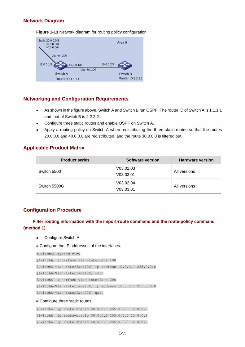
1-55
Network Diagram
Figure 1-13 Network diagram for routing policy configuration
Area 0
Vlan-Int 200
Router ID:1.1.1.1
Switch A Switch BRouter ID:2.2.2.2
12.0.0.1/8
Static 20.0.0.0/8 30.0.0.0/8 40.0.0.0/8
10.0.0.1/8 10.0.0.2/8
Vlan-Int 100
Networking and Configuration Requirements
As shown in the figure above, Switch A and Switch B run OSPF. The router ID of Switch A is 1.1.1.1 and that of Switch B is 2.2.2.2.
Configure three static routes and enable OSPF on Switch A. Apply a routing policy on Switch A when redistributing the three static routes so that the routes
20.0.0.0 and 40.0.0.0 are redistributed, and the route 30.0.0.0 is filtered out.
Applicable Product Matrix
Product series Software version Hardware version
Switch 5500 V03.02.03 V03.03.01
All versions
Switch 5500G V03.02.04 V03.03.01
All versions
Configuration Procedure
Filter routing information with the import-route command and the route-policy command (method 1)
Configure Switch A.
# Configure the IP addresses of the interfaces.
<SwitchA> system-view
[SwitchA] interface vlan-interface 100
[SwitchA-Vlan-interface100] ip address 10.0.0.1 255.0.0.0
[SwitchA-Vlan-interface100] quit
[SwitchA] interface vlan-interface 200
[SwitchA-Vlan-interface200] ip address 12.0.0.1 255.0.0.0
[SwitchA-Vlan-interface200] quit
# Configure three static routes.
[SwitchA] ip route-static 20.0.0.0 255.0.0.0 12.0.0.2
[SwitchA] ip route-static 30.0.0.0 255.0.0.0 12.0.0.2
[SwitchA] ip route-static 40.0.0.0 255.0.0.0 12.0.0.2
1-56
# Enable OSPF and specify VLAN-interface 10 to belong to area 0.
[SwitchA] router id 1.1.1.1
[SwitchA] ospf
[SwitchA-ospf-1] area 0
[SwitchA-ospf-1-area-0.0.0.0] network 10.0.0.0 0.255.255.255
[SwitchA-ospf-1-area-0.0.0.0] quit
[SwitchA-ospf-1]quit
# Configure an ACL.
[SwitchA] acl number 2000
[SwitchA-acl-basic-2000] rule deny source 30.0.0.0 0.255.255.255
[SwitchA-acl-basic-2000] rule permit source any
[SwitchA-acl-basic-2000] quit
# Configure a routing policy.
[SwitchA] route-policy ospf permit node 10
[SwitchA-route-policy] if-match acl 2000
[SwitchA-route-policy] quit
# Apply the routing policy when the static routes are redistributed.
[SwitchA] ospf
[SwitchA-ospf-1] import-route static route-policy ospf
Configure Switch B.
# Configure the IP address of the interface.
<SwitchB> system-view
[SwitchB] interface vlan-interface 100
[SwitchB-Vlan-interface100] ip address 10.0.0.2 255.0.0.0
[SwitchB-Vlan-interface100] quit
# Enable OSPF and specify VLAN interface 100 to belong to area 0.
[SwitchB] router id 2.2.2.2
[SwitchB] ospf
[SwitchB-ospf-1] area 0
[SwitchB-ospf-1-area-0.0.0.0] network 10.0.0.0 0.255.255.255
[SwitchB-ospf-1-area-0.0.0.0] quit
[SwitchB-ospf-1] quit
Filter routing information with the import-route command and the filter-policy export command (method 2)
Configure Switch A.
# Configure the IP addresses of the interfaces.
<SwitchA> system-view
[SwitchA] interface vlan-interface 100
[SwitchA-Vlan-interface100] ip address 10.0.0.1 255.0.0.0
[SwitchA-Vlan-interface100] quit
[SwitchA] interface vlan-interface 200
[SwitchA-Vlan-interface200] ip address 12.0.0.1 255.0.0.0
[SwitchA-Vlan-interface200] quit
1-57
# Configure three static routes.
[SwitchA] ip route-static 20.0.0.0 255.0.0.0 12.0.0.2
[SwitchA] ip route-static 30.0.0.0 255.0.0.0 12.0.0.2
[SwitchA] ip route-static 40.0.0.0 255.0.0.0 12.0.0.2
# Enable OSPF and specify VLAN interface 100 to belong to area 0.
[SwitchA] router id 1.1.1.1
[SwitchA] ospf
[SwitchA-ospf-1] area 0
[SwitchA-ospf-1-area-0.0.0.0] network 10.0.0.0 0.255.255.255
[SwitchA-ospf-1-area-0.0.0.0] quit
[SwitchA-ospf-1] quit
# Configure an ACL.
[SwitchA] acl number 2000
[SwitchA-acl-basic-2000] rule deny source 30.0.0.0 0.255.255.255
[SwitchA-acl-basic-2000] rule permit source any
[SwitchA-acl-basic-2000] quit
# Apply ACL 2000 to filter the advertised routes.
[SwitchA] ospf
[SwitchA-ospf-1] filter-policy 2000 export
# Redistribute static routes.
[SwitchA-ospf-1] import-route static
Configure Switch B.
The configuration on Switch B is the same as that in method 1. Refer to the configuration on Switch B in Configuration Procedure.
Filter routing information with the import-route command and the asbr-summary not-advertise command (method 3)
Configure Switch A.
# Configure the IP addresses of the interfaces.
<SwitchA> system-view
[SwitchA] interface vlan-interface 100
[SwitchA-Vlan-interface100] ip address 10.0.0.1 255.0.0.0
[SwitchA-Vlan-interface100] quit
[SwitchA] interface vlan-interface 200
[SwitchA-Vlan-interface200] ip address 12.0.0.1 255.0.0.0
[SwitchA-Vlan-interface200] quit
# Configure three static routes.
[SwitchA] ip route-static 20.0.0.0 255.0.0.0 12.0.0.2
[SwitchA] ip route-static 30.0.0.0 255.0.0.0 12.0.0.2
[SwitchA] ip route-static 40.0.0.0 255.0.0.0 12.0.0.2
# Enable OSPF and specify VLAN interface 100 to belong to area 0.
[SwitchA] router id 1.1.1.1
[SwitchA] ospf
1-58
[SwitchA-ospf-1] area 0
[SwitchA-ospf-1-area-0.0.0.0] network 10.0.0.0 0.255.255.255
[SwitchA-ospf-1-area-0.0.0.0] quit
# Configure route summarization to prevent network 30.0.0.0/8 from being advertised.
[SwitchA-ospf-1] asbr-summary 30.0.0.0 255.0.0.0 not-advertise
# Redistribute the static routes.
[SwitchA-ospf-1] import-route static
Configure Switch B.
The configuration on Switch B is the same as that in method 1. Refer to the configuration on Switch B in Configuration Procedure.
Complete Configuration
In the following complete configuration, the import-route command and the route-policy command are used to filter routing information (method 1). For the complete configurations of other methods, refer to Configuration Procedure.
Perform the following configuration on Switch A. #
router id 1.1.1.1
#
acl number 2000
rule 0 deny source 30.0.0.0 0.255.255.255
rule 1 permit
#
vlan 100
#
vlan 200
#
interface Vlan-interface100
ip address 10.0.0.1 255.0.0.0
#
interface Vlan-interface200
ip address 12.0.0.1 255.0.0.0
#
ospf 1
import-route static route-policy ospf
area 0.0.0.0
network 10.0.0.0 0.255.255.255
#
route-policy ospf permit node 10
if-match acl 2000
#
ip route-static 20.0.0.0 255.0.0.0 12.0.0.2 preference 60
ip route-static 30.0.0.0 255.0.0.0 12.0.0.2 preference 60
ip route-static 40.0.0.0 255.0.0.0 12.0.0.2 preference 60
#
1-59
Perform the following configuration on Switch B. #
router id 2.2.2.2
#
vlan 100
#
interface Vlan-interface100
ip address 10.0.0.2 255.0.0.0
#
ospf 1
area 0.0.0.0
network 10.0.0.0 0.255.255.255
#
Precautions
In an OSPF network, when an ASBR redistributes routes, you can use the command combination of filter-policy export and import-route, route-policy and import-route, or import-route and asbr-summary not-advertise to filter redistributed routing information based on the actual conditions.
i
Table of Contents
1 Multicast Configuration Guide ·················································································································1-1 Configuring IGMP Snooping ···················································································································1-1
Network Diagram·····························································································································1-1 Networking and Configuration Requirements··················································································1-1 Application Product Matrix···············································································································1-1 Configuration Procedure··················································································································1-2 Complete Configuration···················································································································1-3 Precautions······································································································································1-3
Configuring IGMP Snooping Only···········································································································1-4 Network Diagram·····························································································································1-4 Networking and Configuration Requirements··················································································1-4 Application Product Matrix···············································································································1-4 Configuration Procedure··················································································································1-5 Complete Configuration···················································································································1-8
Configuring Multicast VLAN ····················································································································1-9 Network Diagram·····························································································································1-9 Networking and Configuration Requirements··················································································1-9 Application Product Matrix·············································································································1-10 Configuration Procedure················································································································1-10 Complete Configuration·················································································································1-12 Precautions····································································································································1-13
Configuring PIM-SM plus IGMP plus IGMP Snooping··········································································1-13 Network Diagram···························································································································1-14 Networking and Configuration Requirements················································································1-14 Application Product Matrix·············································································································1-15 Configuration Procedure················································································································1-15 Complete Configuration·················································································································1-20 Precautions····································································································································1-22
Configuring PIM-DM plus IGMP············································································································1-23 Network Diagram···························································································································1-23 Networking and Configuration Requirements················································································1-24 Application Product Matrix·············································································································1-24 Configuration Procedure················································································································1-24 Complete Configuration·················································································································1-26 Precautions····································································································································1-27
Configuring Anycast RP Application ·····································································································1-27 Network Diagram···························································································································1-28 Networking and Configuration Requirements················································································1-28 Application Product Matrix·············································································································1-28 Configuration Procedure················································································································1-29 Complete Configuration·················································································································1-31 Precautions····································································································································1-33
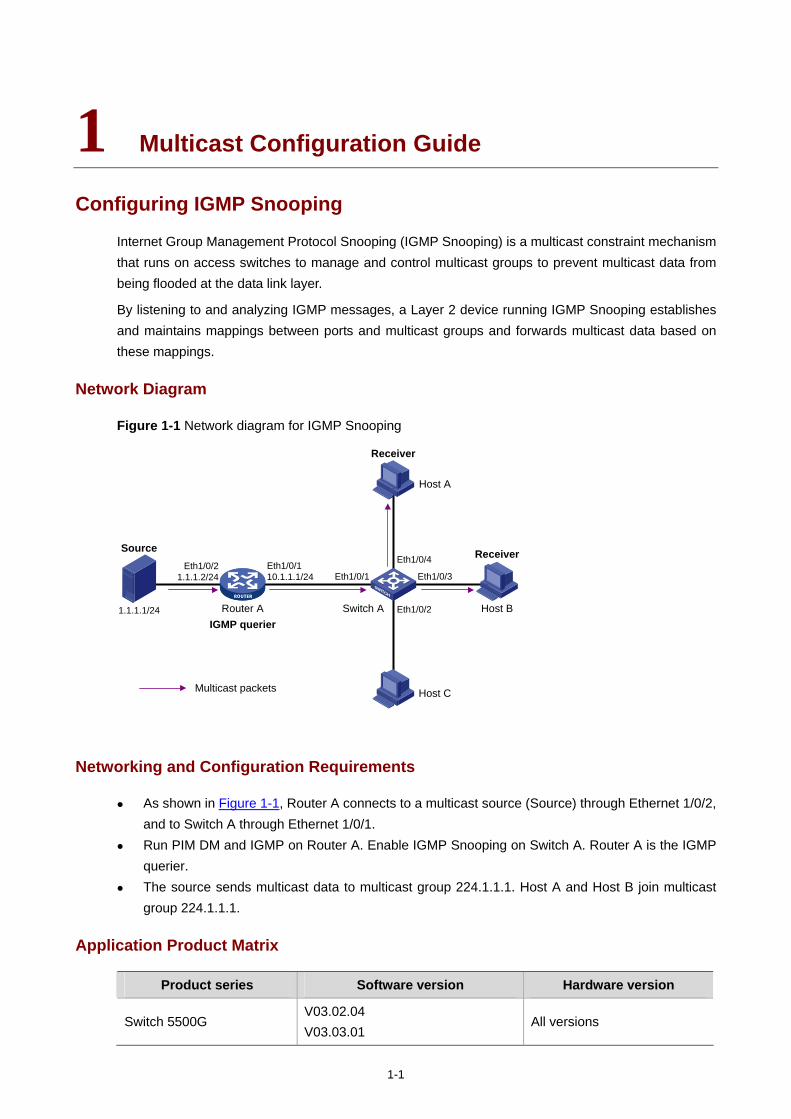
1-1
1 Multicast Configuration Guide
Configuring IGMP Snooping
Internet Group Management Protocol Snooping (IGMP Snooping) is a multicast constraint mechanism that runs on access switches to manage and control multicast groups to prevent multicast data from being flooded at the data link layer.
By listening to and analyzing IGMP messages, a Layer 2 device running IGMP Snooping establishes and maintains mappings between ports and multicast groups and forwards multicast data based on these mappings.
Network Diagram
Figure 1-1 Network diagram for IGMP Snooping
Multicast packets
Source
Router A Switch A
Receiver
Receiver
Host B
Host A
Host C
1.1.1.1/24
Eth1/0/4
Eth1/0/2
Eth1/0/3
IGMP querier
Eth1/0/1Eth1/0/110.1.1.1/24
Eth1/0/21.1.1.2/24
Networking and Configuration Requirements
As shown in Figure 1-1, Router A connects to a multicast source (Source) through Ethernet 1/0/2, and to Switch A through Ethernet 1/0/1.
Run PIM DM and IGMP on Router A. Enable IGMP Snooping on Switch A. Router A is the IGMP querier.
The source sends multicast data to multicast group 224.1.1.1. Host A and Host B join multicast group 224.1.1.1.
Application Product Matrix
Product series Software version Hardware version
Switch 5500G V03.02.04 V03.03.01
All versions
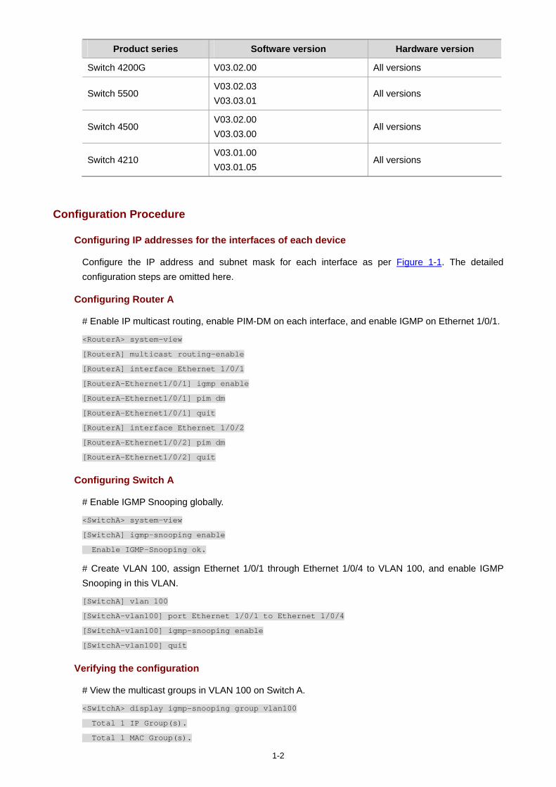
1-2
Product series Software version Hardware version
Switch 4200G V03.02.00 All versions
Switch 5500 V03.02.03 V03.03.01
All versions
Switch 4500 V03.02.00 V03.03.00
All versions
Switch 4210 V03.01.00 V03.01.05
All versions
Configuration Procedure
Configuring IP addresses for the interfaces of each device
Configure the IP address and subnet mask for each interface as per Figure 1-1. The detailed configuration steps are omitted here.
Configuring Router A
# Enable IP multicast routing, enable PIM-DM on each interface, and enable IGMP on Ethernet 1/0/1.
<RouterA> system-view
[RouterA] multicast routing-enable
[RouterA] interface Ethernet 1/0/1
[RouterA-Ethernet1/0/1] igmp enable
[RouterA-Ethernet1/0/1] pim dm
[RouterA-Ethernet1/0/1] quit
[RouterA] interface Ethernet 1/0/2
[RouterA-Ethernet1/0/2] pim dm
[RouterA-Ethernet1/0/2] quit
Configuring Switch A
# Enable IGMP Snooping globally.
<SwitchA> system-view
[SwitchA] igmp-snooping enable
Enable IGMP-Snooping ok.
# Create VLAN 100, assign Ethernet 1/0/1 through Ethernet 1/0/4 to VLAN 100, and enable IGMP Snooping in this VLAN.
[SwitchA] vlan 100
[SwitchA-vlan100] port Ethernet 1/0/1 to Ethernet 1/0/4
[SwitchA-vlan100] igmp-snooping enable
[SwitchA-vlan100] quit
Verifying the configuration
# View the multicast groups in VLAN 100 on Switch A.
<SwitchA> display igmp-snooping group vlan100
Total 1 IP Group(s).
Total 1 MAC Group(s).
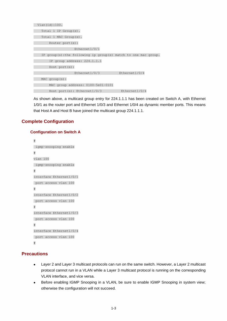
1-3
Vlan(id):100.
Total 1 IP Group(s).
Total 1 MAC Group(s).
Router port(s):
Ethernet1/0/1
IP group(s):the following ip group(s) match to one mac group.
IP group address: 224.1.1.1
Host port(s):
Ethernet1/0/3 Ethernet1/0/4
MAC group(s):
MAC group address: 0100-5e01-0101
Host port(s): Ethernet1/0/3 Ethernet1/0/4
As shown above, a multicast group entry for 224.1.1.1 has been created on Switch A, with Ethernet 1/0/1 as the router port and Ethernet 1/0/3 and Ethernet 1/0/4 as dynamic member ports. This means that Host A and Host B have joined the multicast group 224.1.1.1.
Complete Configuration
Configuration on Switch A
#
igmp-snooping enable
#
vlan 100
igmp-snooping enable
#
interface Ethernet1/0/1
port access vlan 100
#
interface Ethernet1/0/2
port access vlan 100
#
interface Ethernet1/0/3
port access vlan 100
#
interface Ethernet1/0/4
port access vlan 100
#
Precautions
Layer 2 and Layer 3 multicast protocols can run on the same switch. However, a Layer 2 multicast protocol cannot run in a VLAN while a Layer 3 multicast protocol is running on the corresponding VLAN interface, and vice versa.
Before enabling IGMP Snooping in a VLAN, be sure to enable IGMP Snooping in system view; otherwise the configuration will not succeed.
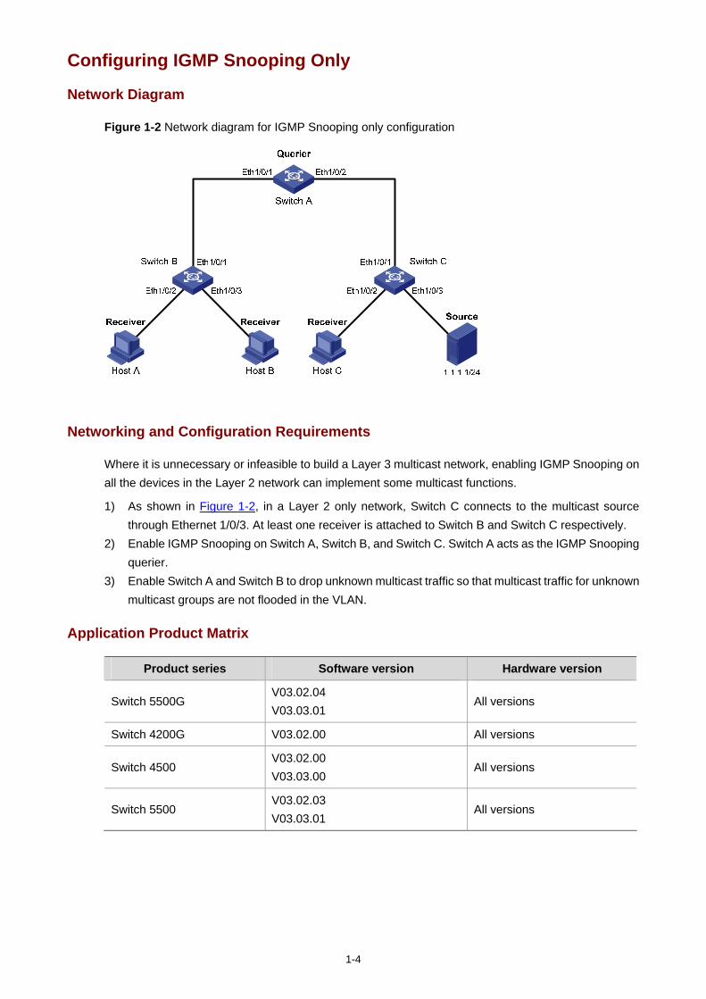
1-4
Configuring IGMP Snooping Only
Network Diagram
Figure 1-2 Network diagram for IGMP Snooping only configuration
Networking and Configuration Requirements
Where it is unnecessary or infeasible to build a Layer 3 multicast network, enabling IGMP Snooping on all the devices in the Layer 2 network can implement some multicast functions.
1) As shown in Figure 1-2, in a Layer 2 only network, Switch C connects to the multicast source through Ethernet 1/0/3. At least one receiver is attached to Switch B and Switch C respectively.
2) Enable IGMP Snooping on Switch A, Switch B, and Switch C. Switch A acts as the IGMP Snooping querier.
3) Enable Switch A and Switch B to drop unknown multicast traffic so that multicast traffic for unknown multicast groups are not flooded in the VLAN.
Application Product Matrix
Product series Software version Hardware version
Switch 5500G V03.02.04 V03.03.01
All versions
Switch 4200G V03.02.00 All versions
Switch 4500 V03.02.00 V03.03.00
All versions
Switch 5500 V03.02.03 V03.03.01
All versions
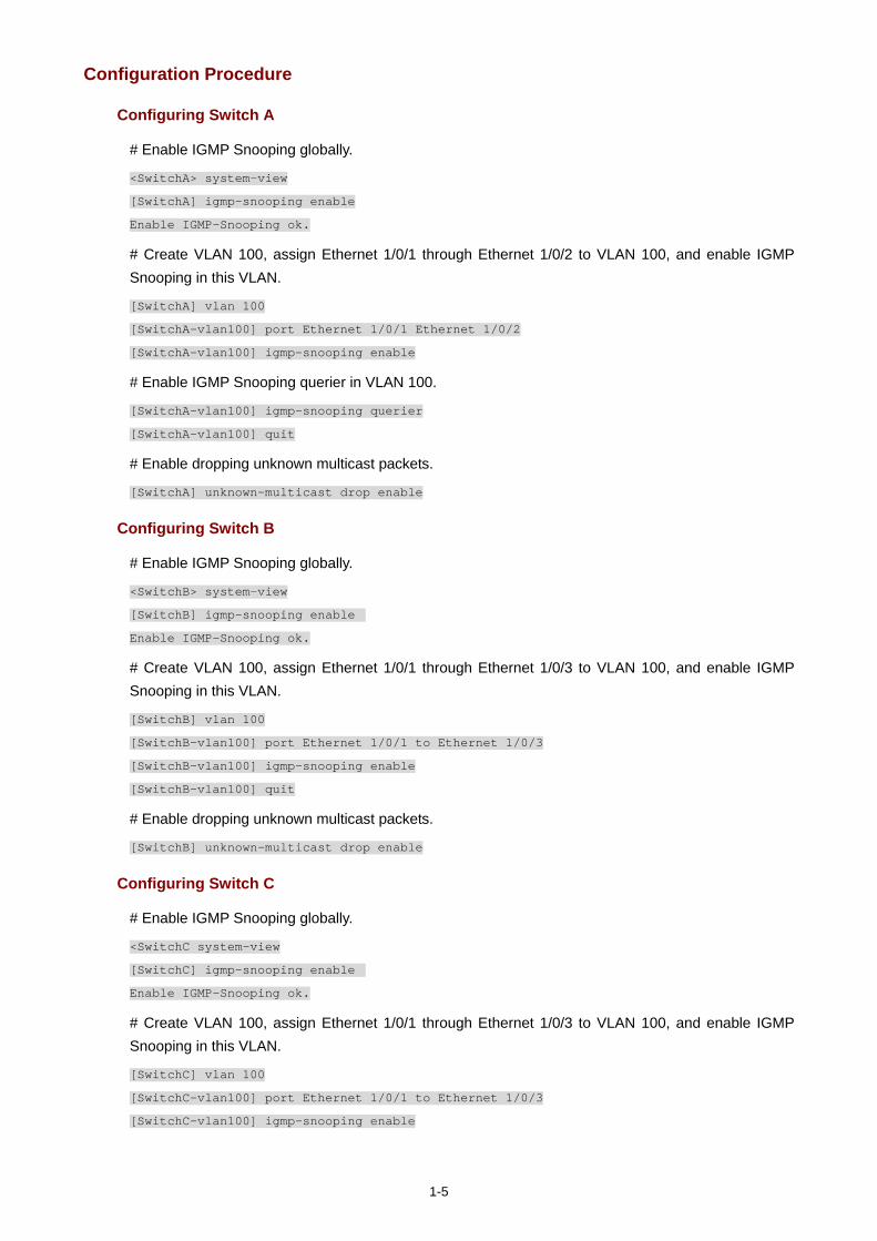
1-5
Configuration Procedure
Configuring Switch A
# Enable IGMP Snooping globally.
<SwitchA> system-view
[SwitchA] igmp-snooping enable
Enable IGMP-Snooping ok.
# Create VLAN 100, assign Ethernet 1/0/1 through Ethernet 1/0/2 to VLAN 100, and enable IGMP Snooping in this VLAN.
[SwitchA] vlan 100
[SwitchA-vlan100] port Ethernet 1/0/1 Ethernet 1/0/2
[SwitchA-vlan100] igmp-snooping enable
# Enable IGMP Snooping querier in VLAN 100.
[SwitchA-vlan100] igmp-snooping querier
[SwitchA-vlan100] quit
# Enable dropping unknown multicast packets.
[SwitchA] unknown-multicast drop enable
Configuring Switch B
# Enable IGMP Snooping globally.
<SwitchB> system-view
[SwitchB] igmp-snooping enable
Enable IGMP-Snooping ok.
# Create VLAN 100, assign Ethernet 1/0/1 through Ethernet 1/0/3 to VLAN 100, and enable IGMP Snooping in this VLAN.
[SwitchB] vlan 100
[SwitchB-vlan100] port Ethernet 1/0/1 to Ethernet 1/0/3
[SwitchB-vlan100] igmp-snooping enable
[SwitchB-vlan100] quit
# Enable dropping unknown multicast packets.
[SwitchB] unknown-multicast drop enable
Configuring Switch C
# Enable IGMP Snooping globally.
<SwitchC system-view
[SwitchC] igmp-snooping enable
Enable IGMP-Snooping ok.
# Create VLAN 100, assign Ethernet 1/0/1 through Ethernet 1/0/3 to VLAN 100, and enable IGMP Snooping in this VLAN.
[SwitchC] vlan 100
[SwitchC-vlan100] port Ethernet 1/0/1 to Ethernet 1/0/3
[SwitchC-vlan100] igmp-snooping enable
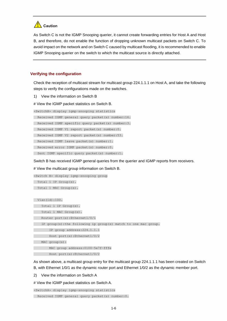
1-6
As Switch C is not the IGMP Snooping querier, it cannot create forwarding entries for Host A and Host B, and therefore, do not enable the function of dropping unknown multicast packets on Switch C. To avoid impact on the network and on Switch C caused by multicast flooding, it is recommended to enable IGMP Snooping querier on the switch to which the multicast source is directly attached.
Verifying the configuration
Check the reception of multicast stream for multicast group 224.1.1.1 on Host A, and take the following steps to verify the configurations made on the switches.
1) View the information on Switch B
# View the IGMP packet statistics on Switch B.
<SwitchB> display igmp-snooping statistics
Received IGMP general query packet(s) number:16.
Received IGMP specific query packet(s) number:3.
Received IGMP V1 report packet(s) number:0.
Received IGMP V2 report packet(s) number:53.
Received IGMP leave packet(s) number:1.
Received error IGMP packet(s) number:0.
Sent IGMP specific query packet(s) number:1.
Switch B has received IGMP general queries from the querier and IGMP reports from receivers.
# View the multicast group information on Switch B.
<Switch B> display igmp-snooping group
Total 1 IP Group(s).
Total 1 MAC Group(s).
Vlan(id):100.
Total 1 IP Group(s).
Total 1 MAC Group(s).
Router port(s):Ethernet1/0/1
IP group(s):the following ip group(s) match to one mac group.
IP group address:224.1.1.1
Host port(s):Ethernet1/0/2
MAC group(s):
MAC group address:0100-5e7f-fffe
Host port(s):Ethernet1/0/2
As shown above, a multicast group entry for the multicast group 224.1.1.1 has been created on Switch B, with Ethernet 1/0/1 as the dynamic router port and Ethernet 1/0/2 as the dynamic member port.
2) View the information on Switch A
# View the IGMP packet statistics on Switch A.
<SwitchA> display igmp-snooping statistics
Received IGMP general query packet(s) number:0.

1-7
Received IGMP specific query packet(s) number:0.
Received IGMP V1 report packet(s) number:0.
Received IGMP V2 report packet(s) number:53.
Received IGMP leave packet(s) number:1.
Received error IGMP packet(s) number:0.
Sent IGMP specific query packet(s) number:1.
Switch A receives IGMP reports from the receivers.
# View the multicast group information on Switch A.
<Switch A> display igmp-snooping group
Total 1 IP Group(s).
Total 1 MAC Group(s).
Vlan(id):100.
Total 1 IP Group(s).
Total 1 MAC Group(s).
Router port(s):
IP group(s):the following ip group(s) match to one mac group.
IP group address:224.1.1.1
Host port(s):Ethernet1/0/1
MAC group(s):
MAC group address:0100-5e7f-fffe
Host port(s):Ethernet1/0/1
As shown above, a multicast group entry for the multicast group 224.1.1.1 has been created on Switch A, with Ethernet 1/0/1 as the dynamic member port. Acting as the IGMP Snooping querier, Switch A does not have a router port.
3) View the information on Switch C
# View the IGMP packet statistics on Switch C.
<SwitchC> display igmp-snooping statistics
Received IGMP general query packet(s) number:10.
Received IGMP specific query packet(s) number:0.
Received IGMP V1 report packet(s) number:0.
Received IGMP V2 report packet(s) number:0.
Received IGMP leave packet(s) number:.0
Received error IGMP packet(s) number:0.
Sent IGMP specific query packet(s) number:0.
Switch C received only IGMP general queries from the querier.
# View the multicast group information on Switch C.
<Switch C> display igmp-snooping group
Total 0 IP Group(s).
Total 0 MAC Group(s).
Vlan(id):100.
Total 0 IP Group(s).
Total 0 MAC Group(s).
Router port(s):Ethernet1/0/1
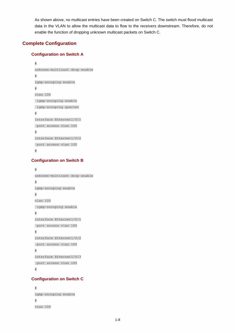
1-8
As shown above, no multicast entries have been created on Switch C. The switch must flood multicast data in the VLAN to allow the multicast data to flow to the receivers downstream. Therefore, do not enable the function of dropping unknown multicast packets on Switch C.
Complete Configuration
Configuration on Switch A
#
unknown-multicast drop enable
#
igmp-snooping enable
#
vlan 100
igmp-snooping enable
igmp-snooping querier
#
interface Ethernet1/0/1
port access vlan 100
#
interface Ethernet1/0/2
port access vlan 100
#
Configuration on Switch B
#
unknown-multicast drop enable
#
igmp-snooping enable
#
vlan 100
igmp-snooping enable
#
interface Ethernet1/0/1
port access vlan 100
#
interface Ethernet1/0/2
port access vlan 100
#
interface Ethernet1/0/3
port access vlan 100
#
Configuration on Switch C
#
igmp-snooping enable
#
vlan 100
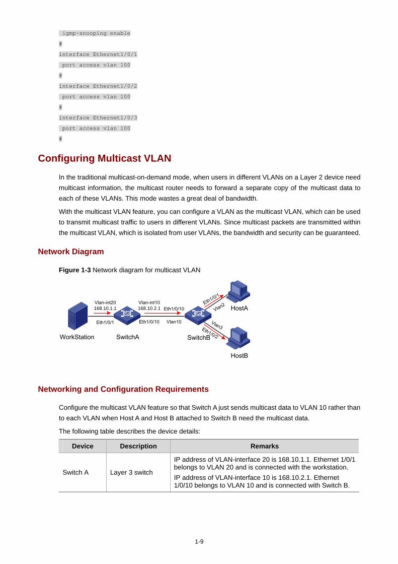
1-9
igmp-snooping enable
#
interface Ethernet1/0/1
port access vlan 100
#
interface Ethernet1/0/2
port access vlan 100
#
interface Ethernet1/0/3
port access vlan 100
#
Configuring Multicast VLAN
In the traditional multicast-on-demand mode, when users in different VLANs on a Layer 2 device need multicast information, the multicast router needs to forward a separate copy of the multicast data to each of these VLANs. This mode wastes a great deal of bandwidth.
With the multicast VLAN feature, you can configure a VLAN as the multicast VLAN, which can be used to transmit multicast traffic to users in different VLANs. Since multicast packets are transmitted within the multicast VLAN, which is isolated from user VLANs, the bandwidth and security can be guaranteed.
Network Diagram
Figure 1-3 Network diagram for multicast VLAN
WorkStation SwitchA SwitchB
Vlan-int20168.10.1.1
Eth1/0/1 Eth1/0/10
Vlan2
Vlan3
Eth1/0/10
Vlan10
Eth1/0/
1
Eth1/0/2
HostA
HostB
Vlan-int10168.10.2.1
Networking and Configuration Requirements
Configure the multicast VLAN feature so that Switch A just sends multicast data to VLAN 10 rather than to each VLAN when Host A and Host B attached to Switch B need the multicast data.
The following table describes the device details:
Device Description Remarks
Switch A Layer 3 switch
IP address of VLAN-interface 20 is 168.10.1.1. Ethernet 1/0/1 belongs to VLAN 20 and is connected with the workstation. IP address of VLAN-interface 10 is 168.10.2.1. Ethernet 1/0/10 belongs to VLAN 10 and is connected with Switch B.
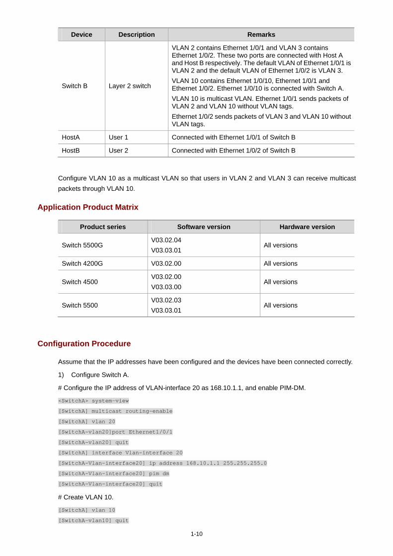
1-10
Device Description Remarks
Switch B Layer 2 switch
VLAN 2 contains Ethernet 1/0/1 and VLAN 3 contains Ethernet 1/0/2. These two ports are connected with Host A and Host B respectively. The default VLAN of Ethernet 1/0/1 is VLAN 2 and the default VLAN of Ethernet 1/0/2 is VLAN 3. VLAN 10 contains Ethernet 1/0/10, Ethernet 1/0/1 and Ethernet 1/0/2. Ethernet 1/0/10 is connected with Switch A. VLAN 10 is multicast VLAN. Ethernet 1/0/1 sends packets of VLAN 2 and VLAN 10 without VLAN tags. Ethernet 1/0/2 sends packets of VLAN 3 and VLAN 10 without VLAN tags.
HostA User 1 Connected with Ethernet 1/0/1 of Switch B
HostB User 2 Connected with Ethernet 1/0/2 of Switch B
Configure VLAN 10 as a multicast VLAN so that users in VLAN 2 and VLAN 3 can receive multicast packets through VLAN 10.
Application Product Matrix
Product series Software version Hardware version
Switch 5500G V03.02.04 V03.03.01
All versions
Switch 4200G V03.02.00 All versions
Switch 4500 V03.02.00 V03.03.00
All versions
Switch 5500 V03.02.03 V03.03.01
All versions
Configuration Procedure
Assume that the IP addresses have been configured and the devices have been connected correctly.
1) Configure Switch A.
# Configure the IP address of VLAN-interface 20 as 168.10.1.1, and enable PIM-DM.
<SwitchA> system-view
[SwitchA] multicast routing-enable
[SwitchA] vlan 20
[SwitchA–vlan20]port Ethernet1/0/1
[SwitchA-vlan20] quit
[SwitchA] interface Vlan-interface 20
[SwitchA-Vlan-interface20] ip address 168.10.1.1 255.255.255.0
[SwitchA-Vlan-interface20] pim dm
[SwitchA-Vlan-interface20] quit
# Create VLAN 10.
[SwitchA] vlan 10
[SwitchA-vlan10] quit
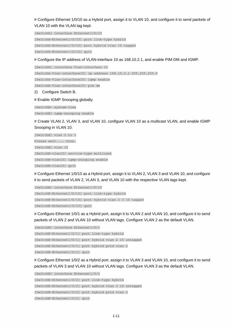
1-11
# Configure Ethernet 1/0/10 as a Hybrid port, assign it to VLAN 10, and configure it to send packets of VLAN 10 with the VLAN tag kept.
[SwitchA] interface Ethernet1/0/10
[SwitchA-Ethernet1/0/10] port link-type hybrid
[SwitchA-Ethernet1/0/10] port hybrid vlan 10 tagged
[SwitchA-Ethernet1/0/10] quit
# Configure the IP address of VLAN-interface 10 as 168.10.2.1, and enable PIM-DM and IGMP.
[SwitchA] interface Vlan-interface 10
[SwitchA-Vlan-interface10] ip address 168.10.2.1 255.255.255.0
[SwitchA-Vlan-interface10] igmp enable
[SwitchA-Vlan-interface10] pim dm
2) Configure Switch B.
# Enable IGMP Snooping globally.
<SwitchB> system-view
[SwitchB] igmp-snooping enable
# Create VLAN 2, VLAN 3, and VLAN 10, configure VLAN 10 as a multicast VLAN, and enable IGMP Snooping in VLAN 10.
[SwitchB] vlan 2 to 3
Please wait.... Done.
[SwitchB] vlan 10
[SwitchB-vlan10] service-type multicast
[SwitchB-vlan10] igmp-snooping enable
[SwitchB-vlan10] quit
# Configure Ethernet 1/0/10 as a Hybrid port, assign it to VLAN 2, VLAN 3 and VLAN 10, and configure it to send packets of VLAN 2, VLAN 3, and VLAN 10 with the respective VLAN tags kept.
[SwitchB] interface Ethernet1/0/10
[SwitchB-Ethernet1/0/10] port link-type hybrid
[SwitchB-Ethernet1/0/10] port hybrid vlan 2 3 10 tagged
[SwitchB-Ethernet1/0/10] quit
# Configure Ethernet 1/0/1 as a Hybrid port, assign it to VLAN 2 and VLAN 10, and configure it to send packets of VLAN 2 and VLAN 10 without VLAN tags. Configure VLAN 2 as the default VLAN.
[SwitchB] interface Ethernet1/0/1
[SwitchB-Ethernet1/0/1] port link-type hybrid
[SwitchB-Ethernet1/0/1] port hybrid vlan 2 10 untagged
[SwitchB-Ethernet1/0/1] port hybrid pvid vlan 2
[SwitchB-Ethernet1/0/1] quit
# Configure Ethernet 1/0/2 as a Hybrid port, assign it to VLAN 3 and VLAN 10, and configure it to send packets of VLAN 3 and VLAN 10 without VLAN tags. Configure VLAN 3 as the default VLAN.
[SwitchB] interface Ethernet1/0/2
[SwitchB-Ethernet1/0/2] port link-type hybrid
[SwitchB-Ethernet1/0/2] port hybrid vlan 3 10 untagged
[SwitchB-Ethernet1/0/2] port hybrid pvid vlan 3
[SwitchB-Ethernet1/0/2] quit
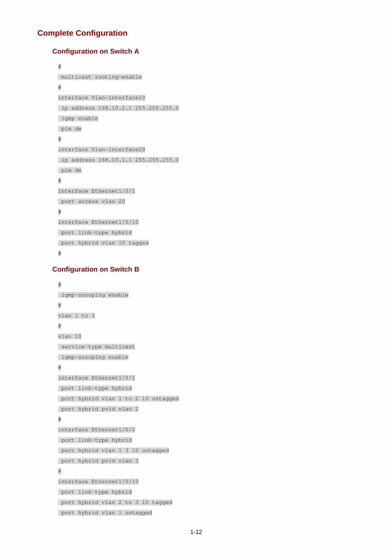
1-12
Complete Configuration
Configuration on Switch A
#
multicast routing-enable
#
interface Vlan-interface10
ip address 168.10.2.1 255.255.255.0
igmp enable
pim dm
#
interface Vlan-interface20
ip address 168.10.1.1 255.255.255.0
pim dm
#
interface Ethernet1/0/1
port access vlan 20
#
interface Ethernet1/0/10
port link-type hybrid
port hybrid vlan 10 tagged
#
Configuration on Switch B
#
igmp-snooping enable
#
vlan 1 to 3
#
vlan 10
service-type multicast
igmp-snooping enable
#
interface Ethernet1/0/1
port link-type hybrid
port hybrid vlan 1 to 2 10 untagged
port hybrid pvid vlan 2
#
interface Ethernet1/0/2
port link-type hybrid
port hybrid vlan 1 3 10 untagged
port hybrid pvid vlan 3
#
interface Ethernet1/0/10
port link-type hybrid
port hybrid vlan 2 to 3 10 tagged
port hybrid vlan 1 untagged
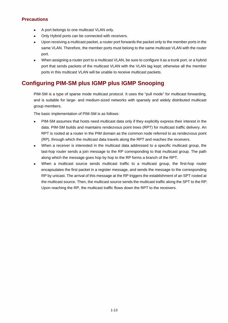
1-13
Precautions
A port belongs to one multicast VLAN only. Only Hybrid ports can be connected with receivers. Upon receiving a multicast packet, a router port forwards the packet only to the member ports in the
same VLAN. Therefore, the member ports must belong to the same multicast VLAN with the router port.
When assigning a router port to a multicast VLAN, be sure to configure it as a trunk port, or a hybrid port that sends packets of the multicast VLAN with the VLAN tag kept; otherwise all the member ports in this multicast VLAN will be unable to receive multicast packets.
Configuring PIM-SM plus IGMP plus IGMP Snooping
PIM-SM is a type of sparse mode multicast protocol. It uses the “pull mode” for multicast forwarding, and is suitable for large- and medium-sized networks with sparsely and widely distributed multicast group members.
The basic implementation of PIM-SM is as follows:
PIM-SM assumes that hosts need multicast data only if they explicitly express their interest in the data. PIM-SM builds and maintains rendezvous point trees (RPT) for multicast traffic delivery. An RPT is rooted at a router in the PIM domain as the common node referred to as rendezvous point (RP), through which the multicast data travels along the RPT and reaches the receivers.
When a receiver is interested in the multicast data addressed to a specific multicast group, the last-hop router sends a join message to the RP corresponding to that multicast group. The path along which the message goes hop by hop to the RP forms a branch of the RPT.
When a multicast source sends multicast traffic to a multicast group, the first-hop router encapsulates the first packet in a register message, and sends the message to the corresponding RP by unicast. The arrival of this message at the RP triggers the establishment of an SPT rooted at the multicast source. Then, the multicast source sends the multicast traffic along the SPT to the RP. Upon reaching the RP, the multicast traffic flows down the RPT to the receivers.
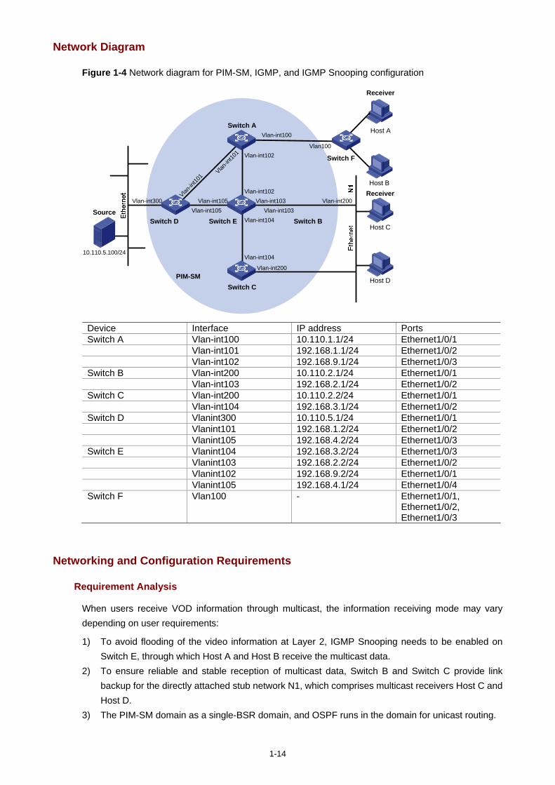
1-14
Network Diagram
Figure 1-4 Network diagram for PIM-SM, IGMP, and IGMP Snooping configuration
Source
10.110.5.100/24
PIM-SM
Switch A
Switch B
Switch C
Switch DHost C
Host D
Receiver
Switch E
Vlan-int200
Vlan-int200
Vlan-int300
Vlan-int102
Vlan-int102
Vlan-in
t101
Vlan-in
t101
Vlan-int103Vlan-int103
Vlan-int104
Vlan-int104
Vlan-int105Vlan-int105
Receiver
Host A
Host B
Vlan-int100
Vlan100
Switch F
Device Interface IP address Ports Switch A Vlan-int100 10.110.1.1/24 Ethernet1/0/1 Vlan-int101 192.168.1.1/24 Ethernet1/0/2 Vlan-int102 192.168.9.1/24 Ethernet1/0/3 Switch B Vlan-int200 10.110.2.1/24 Ethernet1/0/1 Vlan-int103 192.168.2.1/24 Ethernet1/0/2 Switch C Vlan-int200 10.110.2.2/24 Ethernet1/0/1 Vlan-int104 192.168.3.1/24 Ethernet1/0/2 Switch D Vlanint300 10.110.5.1/24 Ethernet1/0/1 Vlanint101 192.168.1.2/24 Ethernet1/0/2 Vlanint105 192.168.4.2/24 Ethernet1/0/3 Switch E Vlanint104 192.168.3.2/24 Ethernet1/0/3 Vlanint103 192.168.2.2/24 Ethernet1/0/2 Vlanint102 192.168.9.2/24 Ethernet1/0/1 Vlanint105 192.168.4.1/24 Ethernet1/0/4 Switch F Vlan100 - Ethernet1/0/1,
Ethernet1/0/2, Ethernet1/0/3
Networking and Configuration Requirements
Requirement Analysis
When users receive VOD information through multicast, the information receiving mode may vary depending on user requirements:
1) To avoid flooding of the video information at Layer 2, IGMP Snooping needs to be enabled on Switch E, through which Host A and Host B receive the multicast data.
2) To ensure reliable and stable reception of multicast data, Switch B and Switch C provide link backup for the directly attached stub network N1, which comprises multicast receivers Host C and Host D.
3) The PIM-SM domain as a single-BSR domain, and OSPF runs in the domain for unicast routing.
1-15
Configuration Plan
1) Switch D connects to the network that comprises the multicast source (Source) through VLAN-interface 300.
2) Switch A connects to Switch F through VLAN-interface 100, and to Switch D and Switch E through VLAN-interface 101 and VLAN-interface 102 respectively.
3) Switch B and Switch C connect to stub network N1 through their respective VLAN-interface 200, and to Switch E through VLAN-interface 103 and VLAN-interface 104 respectively.
4) Both VLAN-interface 105 of Switch D and VLAN-interface 102 of Switch E serve as C-BSRs and C-RPs.
5) Enable IGMPv2 on VLAN-interface 100 of Switch A. On Switch F, enable IGMP Snooping globally and in VLAN 100. Run IGMPv2 on Switch B and Switch C for group management on stub network N1. Typically, Switch B acts as the querier because its interface on the multi-access subnet has a lower IP address.
Application Product Matrix
Product series Software version Hardware version
Switch 5500 V03.02.03 V03.03.01
All versions
Switch 5500G V03.02.04 V03.03.01
All versions
Configuration Procedure
Configuring the interface IP addresses and unicast routing protocol for each switch
Configure the IP address and subnet mask for each interface as per Figure 1-4. The detailed configuration steps are omitted here.
Configure OSPF for interoperation among the switches in the PIM-SM domain. Ensure the network-layer interoperation among Switch A, Switch B, Switch C, Switch D and Switch E in the PIM-SM domain and enable dynamic update of routing information among the switches through a unicast routing protocol. The specific configuration steps are omitted here.
Configuring multicast protocols
# Enable IP multicast routing on Switch A, enable PIM-SM on each interface, and run IGMPv2 on VLAN-interface 100.
<SwitchA> system-view
[SwitchA] multicast routing-enable
[SwitchA] interface Vlan-interface 100
[SwitchA-Vlan-interface100] igmp enable
[SwitchA-Vlan-interface100] pim sm
[SwitchA-Vlan-interface100] quit
[SwitchA] interface vlan-interface 101
[SwitchA-Vlan-interface101] pim sm
[SwitchA-Vlan-interface101] quit
[SwitchA] interface vlan-interface 102
1-16
[SwitchA-Vlan-interface102] pim sm
It is necessary to enable IGMP only on interfaces with multicast receivers attached. The default IGMP version is IGMPv2.
The configuration on Switch B and Switch C is similar to that on Switch A. The configuration on Switch D and Switch E is also similar to that on Switch A except that it is not necessary to enable IGMP on the corresponding interfaces on these two switches.
# Configure the group range to be advertised in C-RP-Adv messages and configure a C-BSR and a C-RP on VLAN-interface 105 of Switch D.
<SwitchD> system-view
[SwitchD] acl number 2005
[SwitchD-acl-basic-2005] rule permit source 225.1.1.0 0.0.0.255
[SwitchD-acl-basic-2005] quit
[SwitchD] pim
[SwitchD-pim] c-bsr vlan-interface 105 24 2
[SwitchD-pim] c-rp vlan-interface 105 group-policy 2005 priority 2
[SwitchD-pim] quit
# Configure the group range to be advertised in C-RP-Adv messages and configure a C-BSR and a C-RP on VLAN-interface 102 of Switch E.
<SwitchE> system-view
[SwitchE] acl number 2005
[SwitchE-acl-basic-2005] rule permit source 225.1.1.0 0.0.0.255
[SwitchE-acl-basic-2005] quit
[SwitchE] pim
[SwitchE-pim] c-bsr vlan-interface 102 24 1
[SwitchE-pim] c-rp vlan-interface 102 group-policy 2005 priority 1
[SwitchE-pim] quit
# On Switch F, enable IGMP Snooping globally and in VLAN 100.
<SwitchF> system-view
[SwitchF] igmp-snooping enable
Enable IGMP-Snooping ok.
[SwitchF] vlan 100
[SwitchF-vlan100] igmp-snooping enable
[SwitchF-vlan100] quit
Verifying the configuration
Check the reception of multicast stream for multicast group 225.1.1.1 on Host A and Host C and verify the configurations made on the switches.
Using the following commands to determine whether Host A and Host C can receive multicast data
# View the PIM neighboring relationships on Switch E.

1-17
<SwitchE> display pim neighbor
Neighbor's Address Interface Name Uptime Expires
192.168.9.1 Vlan-interface102 02:47:04 00:01:42
192.168.2.1 Vlan-interface103 02:45:04 00:04:46
192.168.3.1 Vlan-interface104 02:42:24 00:04:45
192.168.4.2 Vlan-interface105 02:43:44 00:05:44
# View the BSR information on Switch E.
<SwitchE> display pim bsr-info
Current BSR Address: 192.168.4.2
Priority: 2
Mask Length: 24
Expires: 00:01:39
Local Host is C-BSR: 192.168.9.2
Priority: 1
Mask Length: 24
# View the RP information on Switch E.
<SwitchE> display pim rp-info
PIM-SM RP-SET information:
BSR is: 192.168.4.2
Group/MaskLen: 225.1.1.0/24
RP 192.168.9.2
Version: 2
Priority: 1
Uptime: 00:03:15
Expires: 00:01:14
RP 192.168.4.2
Version: 2
Priority: 2
Uptime: 00:04:25
Expires: 00:01:09
# View the PIM routing table on Switch A.
<SwitchA> display pim routing-table
PIM-SM Routing Table
Total 1 (S,G) entries, 1 (*,G) entries, 0 (*,*,RP) entry
(*, 225.1.1.1), RP 192.168.9.2
Protocol 0x20: PIMSM, Flag 0x2003: RPT WC NULL_IIF
Uptime: 00:23:21, never timeout
Upstream interface: Vlan-interface102, RPF neighbor: 192.168.9.2
Downstream interface list:
Vlan-interface100, Protocol 0x1: IGMP, never timeout
(10.110.5.100, 225.1.1.1)
Protocol 0x20: PIMSM, Flag 0x80004: SPT
Uptime: 00:03:43, Timeout in 199 sec
Upstream interface: Vlan-interface102, RPF neighbor: 192.168.9.2

1-18
Downstream interface list:
Vlan-interface100, Protocol 0x1: IGMP, never timeout
Matched 1 (S,G) entries, 1 (*,G) entries, 0 (*,*,RP) entry
The information on Switch B and Switch C is similar to that on Switch A.
# View the PIM routing table on Switch D.
<SwitchD> display pim routing-table
PIM-SM Routing Table
Total 1 (S,G) entry, 0 (*,G) entry, 0 (*,*,RP) entry
(10.110.5.100, 225.1.1.1)
Protocol 0x20: PIMSM, Flag 0x4: SPT
Uptime: 00:03:03, Timeout in 27 sec
Upstream interface: Vlan-interface300, RPF neighbor: NULL
Downstream interface list:
Vlan-interface101, Protocol 0x200: SPT, timeout in 147 sec
Vlan-interface105, Protocol 0x200: SPT, timeout in 145 sec
Matched 1 (S,G) entry, 0 (*,G) entry, 0 (*,*,RP) entry
# View the PIM routing table on Switch E.
<SwitchE> display pim routing-table
PIM-SM Routing Table
Total 1 (S,G) entry, 1 (*,G) entry, 0 (*,*,RP) entry
(*,225.1.1.1), RP 192.168.9.2
Protocol 0x20: PIMSM, Flag 0x2003: RPT WC NULL_IIF
Uptime: 00:02:34, Timeout in 176 sec
Upstream interface: Null, RPF neighbor: 0.0.0.0
Downstream interface list:
Vlan-interface102, Protocol 0x100: RPT, timeout in 176 sec
Vlan-interface103, Protocol 0x100: SPT, timeout in 135 sec
(10.110.5.100, 225.1.1.1)
Protocol 0x20: PIMSM, Flag 0x4: SPT
Uptime: 00:03:03, Timeout in 27 sec
Upstream interface: Vlan-interface105, RPF neighbor: 192.168.4.2
Downstream interface list:
Vlan-interface102, Protocol 0x200: SPT, timeout in 147 sec
Vlan-interface103, Protocol 0x200: SPT, timeout in 145 sec
Matched 1 (S,G) entry, 1 (*,G) entry, 0 (*,*,RP) entry
# View multicast group entries created by IGMP Snooping on Switch F.
<SwitchF> display igmp-snooping group
Total 1 IP Group(s).
Total 1 MAC Group(s).
Vlan(id):100.
Total 1 IP Group(s).
Total 1 MAC Group(s).
1-19
Router port(s):Ethernet1/0/2
IP group(s):the following ip group(s) match to one mac group.
IP group address:225.1.1.1
Host port(s):Ethernet1/0/19
MAC group(s):
MAC group address:0100-5e01-0101
Host port(s):Ethernet1/0/19
# View the multicast group information that contains port information on Switch B.
<SwitchB> display mpm group
Total 1 IP Group(s).
Total 1 MAC Group(s).
Vlan(id):200.
Total 1 IP Group(s).
Total 1 MAC Group(s).
Router port(s):
IP group(s):the following ip group(s) match to one mac group.
IP group address:225.1.1.1
Host port(s):Ethernet1/0/24
MAC group(s):
MAC group address:0100-5e01-0101
Host port(s):Ethernet1/0/24
Vlan(id):103.
Total 0 IP Group(s).
Total 0 MAC Group(s).
Router port(s):Ethernet1/0/10
As shown above, Host A and Host C can receive multicast data.
Configuring simulated joining
Configure simulated joining on Switch B, thus to prevent the multicast switch from considering that no multicast receiver exists on the subnet due to some reasons and pruning the corresponding path from the multicast forwarding tree.
# Configure Ethernet 1/0/21 as a simulated host to join multicast group 225.1.1.1.
<SwitchB> system-view
[SwitchB] interface Vlan-interface 200
[SwitchB-Vlan-interface200] igmp host-join 225.1.1.1 port Ethernet 1/0/21
# View the multicast group information that contains port information on Switch B.
<SwitchB> display mpm group
Total 1 IP Group(s).
Total 1 MAC Group(s).
Vlan(id):200.
Total 1 IP Group(s).
Total 1 MAC Group(s).
Router port(s):
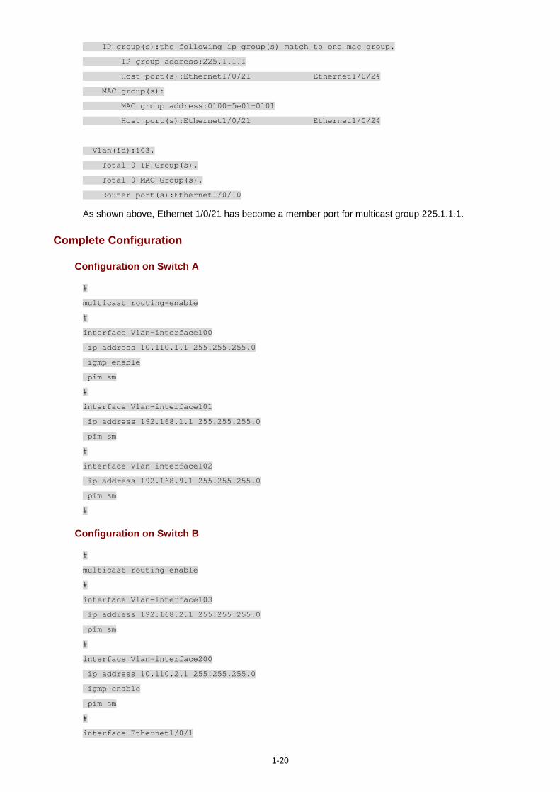
1-20
IP group(s):the following ip group(s) match to one mac group.
IP group address:225.1.1.1
Host port(s):Ethernet1/0/21 Ethernet1/0/24
MAC group(s):
MAC group address:0100-5e01-0101
Host port(s):Ethernet1/0/21 Ethernet1/0/24
Vlan(id):103.
Total 0 IP Group(s).
Total 0 MAC Group(s).
Router port(s):Ethernet1/0/10
As shown above, Ethernet 1/0/21 has become a member port for multicast group 225.1.1.1.
Complete Configuration
Configuration on Switch A
#
multicast routing-enable
#
interface Vlan-interface100
ip address 10.110.1.1 255.255.255.0
igmp enable
pim sm
#
interface Vlan-interface101
ip address 192.168.1.1 255.255.255.0
pim sm
#
interface Vlan-interface102
ip address 192.168.9.1 255.255.255.0
pim sm
#
Configuration on Switch B
#
multicast routing-enable
#
interface Vlan-interface103
ip address 192.168.2.1 255.255.255.0
pim sm
#
interface Vlan-interface200
ip address 10.110.2.1 255.255.255.0
igmp enable
pim sm
#
interface Ethernet1/0/1
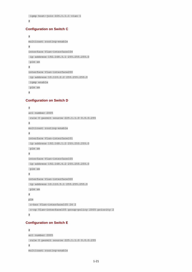
1-21
igmp host-join 225.1.1.1 vlan 1
#
Configuration on Switch C
#
multicast routing-enable
#
interface Vlan-interface104
ip address 192.168.3.1 255.255.255.0
pim sm
#
interface Vlan-interface200
ip address 10.110.2.2 255.255.255.0
igmp enable
pim sm
#
Configuration on Switch D
#
acl number 2005
rule 0 permit source 225.1.1.0 0.0.0.255
#
multicast routing-enable
#
interface Vlan-interface101
ip address 192.168.1.2 255.255.255.0
pim sm
#
interface Vlan-interface105
ip address 192.168.4.2 255.255.255.0
pim sm
#
interface Vlan-interface300
ip address 10.110.5.1 255.255.255.0
pim sm
#
pim
c-bsr Vlan-interface105 24 2
c-rp Vlan-interface105 group-policy 2005 priority 2
#
Configuration on Switch E
#
acl number 2005
rule 0 permit source 225.1.1.0 0.0.0.255
#
multicast routing-enable
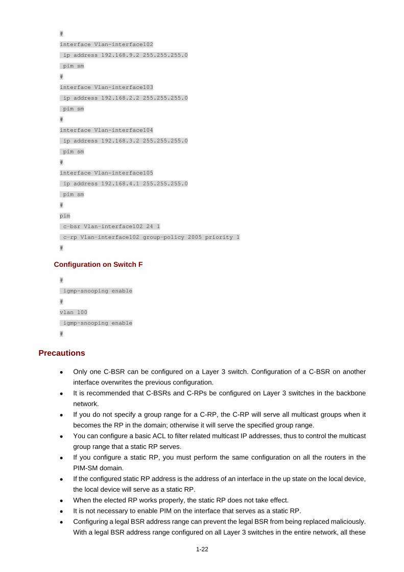
1-22
#
interface Vlan-interface102
ip address 192.168.9.2 255.255.255.0
pim sm
#
interface Vlan-interface103
ip address 192.168.2.2 255.255.255.0
pim sm
#
interface Vlan-interface104
ip address 192.168.3.2 255.255.255.0
pim sm
#
interface Vlan-interface105
ip address 192.168.4.1 255.255.255.0
pim sm
#
pim
c-bsr Vlan-interface102 24 1
c-rp Vlan-interface102 group-policy 2005 priority 1
#
Configuration on Switch F
#
igmp-snooping enable
#
vlan 100
igmp-snooping enable
#
Precautions
Only one C-BSR can be configured on a Layer 3 switch. Configuration of a C-BSR on another interface overwrites the previous configuration.
It is recommended that C-BSRs and C-RPs be configured on Layer 3 switches in the backbone network.
If you do not specify a group range for a C-RP, the C-RP will serve all multicast groups when it becomes the RP in the domain; otherwise it will serve the specified group range.
You can configure a basic ACL to filter related multicast IP addresses, thus to control the multicast group range that a static RP serves.
If you configure a static RP, you must perform the same configuration on all the routers in the PIM-SM domain.
If the configured static RP address is the address of an interface in the up state on the local device, the local device will serve as a static RP.
When the elected RP works properly, the static RP does not take effect. It is not necessary to enable PIM on the interface that serves as a static RP. Configuring a legal BSR address range can prevent the legal BSR from being replaced maliciously.
With a legal BSR address range configured on all Layer 3 switches in the entire network, all these
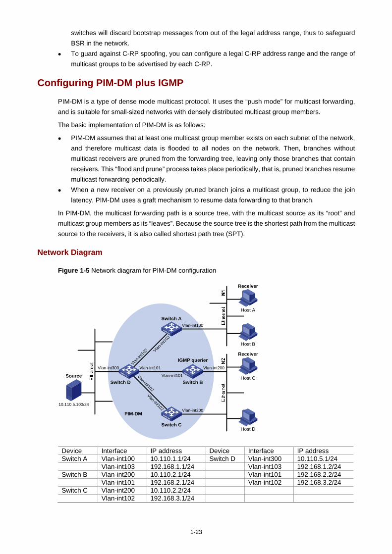
1-23
switches will discard bootstrap messages from out of the legal address range, thus to safeguard BSR in the network.
To guard against C-RP spoofing, you can configure a legal C-RP address range and the range of multicast groups to be advertised by each C-RP.
Configuring PIM-DM plus IGMP
PIM-DM is a type of dense mode multicast protocol. It uses the “push mode” for multicast forwarding, and is suitable for small-sized networks with densely distributed multicast group members.
The basic implementation of PIM-DM is as follows:
PIM-DM assumes that at least one multicast group member exists on each subnet of the network, and therefore multicast data is flooded to all nodes on the network. Then, branches without multicast receivers are pruned from the forwarding tree, leaving only those branches that contain receivers. This “flood and prune” process takes place periodically, that is, pruned branches resume multicast forwarding periodically.
When a new receiver on a previously pruned branch joins a multicast group, to reduce the join latency, PIM-DM uses a graft mechanism to resume data forwarding to that branch.
In PIM-DM, the multicast forwarding path is a source tree, with the multicast source as its “root” and multicast group members as its “leaves”. Because the source tree is the shortest path from the multicast source to the receivers, it is also called shortest path tree (SPT).
Network Diagram
Figure 1-5 Network diagram for PIM-DM configuration
Source
10.110.5.100/24
PIM-DM
Switch A
Switch B
Switch C
Switch D
Receiver
Host A
Host B
Host C
Host D
Receiver
Vlan-int100
Vlan-int200
Vlan-int200
Vlan-int300 Vlan-int101
Vlan-int101
Vlan-int102
Vlan-int102
Vlan-in
t103 Vlan
-int10
3
IGMP querier
Device Interface IP address Device Interface IP address Switch A Vlan-int100 10.110.1.1/24 Switch D Vlan-int300 10.110.5.1/24 Vlan-int103 192.168.1.1/24 Vlan-int103 192.168.1.2/24 Switch B Vlan-int200 10.110.2.1/24 Vlan-int101 192.168.2.2/24 Vlan-int101 192.168.2.1/24 Vlan-int102 192.168.3.2/24 Switch C Vlan-int200 10.110.2.2/24 Vlan-int102 192.168.3.1/24
1-24
Networking and Configuration Requirements
Receivers receive multicast VOD information through multicast. The receiver groups of different organizations form two stub networks, and at least one receiver host exists in each stub network. The entire PIM domain operates in the dense mode.
Host A and Host C are multicast receivers in the two stub networks. Switch D connects to the network that comprises the multicast source (Source) through
VLAN-interface 300. Switch A connects to stub network N1 through VLAN-interface 100, and to Switch D through
VLAN-interface 103. Switch B and Switch C connect to stub network N2 through their respective VLAN-interface 200,
and to Switch D through VLAN-interface 101 and VLAN-interface 102 respectively. IGMPv2 needs to run between Switch A and N1, and also between Switch B, Switch C, and N2.
Typically Switch B acts as the querier.
Application Product Matrix
Product series Software version Hardware version
Switch 5500 V03.02.03 V03.03.01
All versions
Switch 5500G V03.02.04 V03.03.01
All versions
Configuration Procedure
Configuring the interface IP addresses and unicast routing protocol for each switch
Configure the IP address and subnet mask for each interface as perFigure 1-5. The detailed configuration steps are omitted here.
Configure OSPF for interoperation among the switches in the PIM-DM domain. Ensure the network-layer interoperation among Switch A, Switch B, Switch C, and Switch D in the PIM-DM domain and enable dynamic update of routing information among the switches via unicast.
Enabling IP multicast routing and enabling PIM-DM on each interface
# Enable IP multicast routing on Switch A, enable PIM-DM on each interface, and enable IGMP on VLAN-interface 100, which connects Switch A to the stub network.
<SwitchA> system-view
[SwitchA] multicast routing-enable
[SwitchA] interface vlan-interface 100
[SwitchA-Vlan-interface100] igmp enable
[SwitchA-Vlan-interface100] pim dm
[SwitchA-Vlan-interface100] quit
[SwitchA] interface vlan-interface 103
[SwitchA-Vlan-interface103] pim dm
[SwitchA-Vlan-interface103] quit
The configuration on Switch B and Switch C is similar to the configuration on Switch A.
1-25
# Enable multicast routing on Switch D, and enable PIM-DM on each interface.
<SwitchD> system-view
[SwitchD] multicast routing-enable
[SwitchD] interface vlan-interface 300
[SwitchD-Vlan-interface300] pim dm
[SwitchD-Vlan-interface300] quit
[SwitchD] interface vlan-interface 103
[SwitchD-Vlan-interface103] pim dm
[SwitchD-Vlan-interface103] quit
[SwitchD] interface vlan-interface 101
[SwitchD-Vlan-interface101] pim dm
[SwitchD-Vlan-interface101] quit
[SwitchD] interface vlan-interface 102
[SwitchD-Vlan-interface102] pim dm
[SwitchD-Vlan-interface102] quit
Verifying the configuration
Carry out the display pim neighbor command to view the PIM neighboring relationships among the switches. For example:
# View the PIM neighboring relationships on Switch D.
[SwitchD] display pim neighbor
Neighbor's Address Interface Name Uptime Expires
192.168.1.1 Vlan-interface1 00:47:08 00:01:39
192.168.2.1 Vlan-interface1 00:48:05 00:01:29
192.168.3.1 Vlan-interface1 00:49:08 00:01:34
Use the display pim routing-table command to view the PIM routing information on the switches. For example:
# View the PIM routing table on Switch A.
<SwitchA> display pim routing-table
PIM-DM Routing Table
Total 1 (S,G) entry
(10.110.5.100, 225.1.1.1)
Protocol 0x40: PIMDM, Flag 0xC: SPT NEG_CACHE
Uptime: 00:00:23, Timeout in 187 sec
Upstream interface: Vlan-interface103, RPF neighbor: 192.168.1.2
Downstream interface list:
Vlan-interface100, Protocol 0x1: IGMP, never timeout
Matched 1 (S,G) entry
The displayed information on Switch B and Switch C is similar to that on Switch A.
# View the PIM routing table on Switch D.
<SwitchD> display pim routing-table
PIM-DM Routing Table
Total 1 (S,G) entry
1-26
(10.110.5.100, 225.1.1.1)
Protocol 0x40: PIMDM, Flag 0xC: SPT NEG_CACHE
Uptime: 00:00:23, Timeout in 187 sec
Upstream interface: Vlan-interface300, RPF neighbor: NULL
Downstream interface list:
Vlan-interface101, Protocol 0x200: SPT, timeout in 147 sec
Vlan-interface103, Protocol 0x200: SPT, timeout in 145 sec
Vlan-interface103, Protocol 0x200: SPT, timeout in 145 sec
Matched 1 (S,G) entry
Complete Configuration
Configuration on Switch A
#
multicast routing-enable
#
interface Vlan-interface100
ip address 10.110.1.1 255.255.255.0.
igmp enable
pim dm
#
interface Vlan-interface103
ip address 192.168.1.1 255.255.255.0
pim dm
#
Configuration on Switch B
#
multicast routing-enable
#
interface Vlan-interface101
ip address 192.168.2.1 255.255.255.0.
pim dm
#
interface Vlan-interface200
ip address 10.110.2.1 255.255.255.0
igmp enable
pim dm
#
Configuration on Switch C
#
multicast routing-enable
#
interface Vlan-interface102
1-27
ip address 192.168.3.1 255.255.255.0.
pim dm
#
interface Vlan-interface200
ip address 10.110.2.2 255.255.255.0
igmp enable
pim dm
#
Configuration on Switch D
#
multicast routing-enable
#
interface Vlan-interface101
ip address 192.168.2.2 255.255.255.0.
pim dm
#
interface Vlan-interface102
ip address 192.168.3.2 255.255.255.0
pim dm
#
interface Vlan-interface103
ip address 192.168.1.2 255.255.255.0
pim dm
#
interface Vlan-interface300
ip address 10.110.5.1 255.255.255.0
pim dm
#
Precautions
When deploying a PIM-DM domain, you are recommended to enable PIM-DM on all interfaces of non-border routers.
Configuring Anycast RP Application
Anycast RP enables load balancing and redundancy backup between two or more RPs within a PIM-SM domain by configuring the same IP address for these RPs and establishing MSDP peering relationships between the RPs.
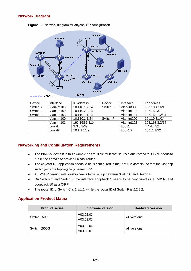
1-28
Network Diagram
Figure 1-6 Network diagram for anycast RP configuration
Loop1
Loop
1
Vlan-int100
Vlan-int100
Device Interface IP address Device Interface IP address Switch A Vlan-int103 10.110.1.2/24 Switch D Vlan-int300 10.110.4.1/24 Switch B Vlan-int100 10.110.2.2/24 Vlan-int102 192.168.3.1 Switch C Vlan-int103 10.110.1.1/24 Vlan-int101 192.168.1.2/24 Vlan-int100 10.110.2.1/24 Switch F Vlan-int200 10.110.3.1/24 Vlan-int101 192.168.1.1/24 Vlan-int102 192.168.3.2/24 Loop1 3.3.3.3/32 Loop1 4.4.4.4/32 Loop10 10.1.1.1/32 Loop10 10.1.1.1/32
Networking and Configuration Requirements
The PIM-SM domain in this example has multiple multicast sources and receivers. OSPF needs to run in the domain to provide unicast routes.
The anycast RP application needs to be is configured in the PIM-SM domain, so that the last-hop switch joins the topologically nearest RP.
An MSDP peering relationship needs to be set up between Switch C and Switch F. On Switch C and Switch F, the interface Loopback 1 needs to be configured as a C-BSR, and
Loopback 10 as a C-RP. The router ID of Switch C is 1.1.1.1, while the router ID of Switch F is 2.2.2.2.
Application Product Matrix
Product series Software version Hardware version
Switch 5500 V03.02.03 V03.03.01
All versions
Switch 5500G V03.02.04 V03.03.01
All versions
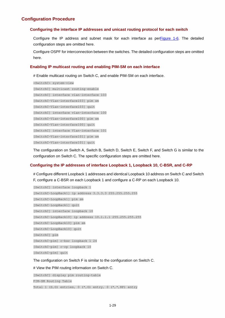
1-29
Configuration Procedure
Configuring the interface IP addresses and unicast routing protocol for each switch
Configure the IP address and subnet mask for each interface as perFigure 1-6. The detailed configuration steps are omitted here.
Configure OSPF for interconnection between the switches. The detailed configuration steps are omitted here.
Enabling IP multicast routing and enabling PIM-SM on each interface
# Enable multicast routing on Switch C, and enable PIM-SM on each interface.
<SwitchC> system-view
[SwitchC] multicast routing-enable
[SwitchC] interface vlan-interface 103
[SwitchC-Vlan-interface103] pim sm
[SwitchC-Vlan-interface103] quit
[SwitchC] interface vlan-interface 100
[SwitchC-Vlan-interface100] pim sm
[SwitchC-Vlan-interface100] quit
[SwitchC] interface Vlan-interface 101
[SwitchC-Vlan-interface101] pim sm
[SwitchC-Vlan-interface101] quit
The configuration on Switch A, Switch B, Switch D, Switch E, Switch F, and Switch G is similar to the configuration on Switch C. The specific configuration steps are omitted here.
Configuring the IP addresses of interface Loopback 1, Loopback 10, C-BSR, and C-RP
# Configure different Loopback 1 addresses and identical Loopback 10 address on Switch C and Switch F, configure a C-BSR on each Loopback 1 and configure a C-RP on each Loopback 10.
[SwitchC] interface loopback 1
[SwitchC-LoopBack1] ip address 3.3.3.3 255.255.255.255
[SwitchC-LoopBack1] pim sm
[SwitchC-LoopBack1] quit
[SwitchC] interface loopback 10
[SwitchC-LoopBack10] ip address 10.1.1.1 255.255.255.255
[SwitchC-LoopBack10] pim sm
[SwitchC-LoopBack10] quit
[SwitchC] pim
[SwitchC-pim] c-bsr loopback 1 24
[SwitchC-pim] c-rp loopback 10
[SwitchC-pim] quit
The configuration on Switch F is similar to the configuration on Switch C.
# View the PIM routing information on Switch C.
[SwitchC] display pim routing-table
PIM-SM Routing Table
Total 1 (S,G) entries, 0 (*,G) entry, 0 (*,*,RP) entry
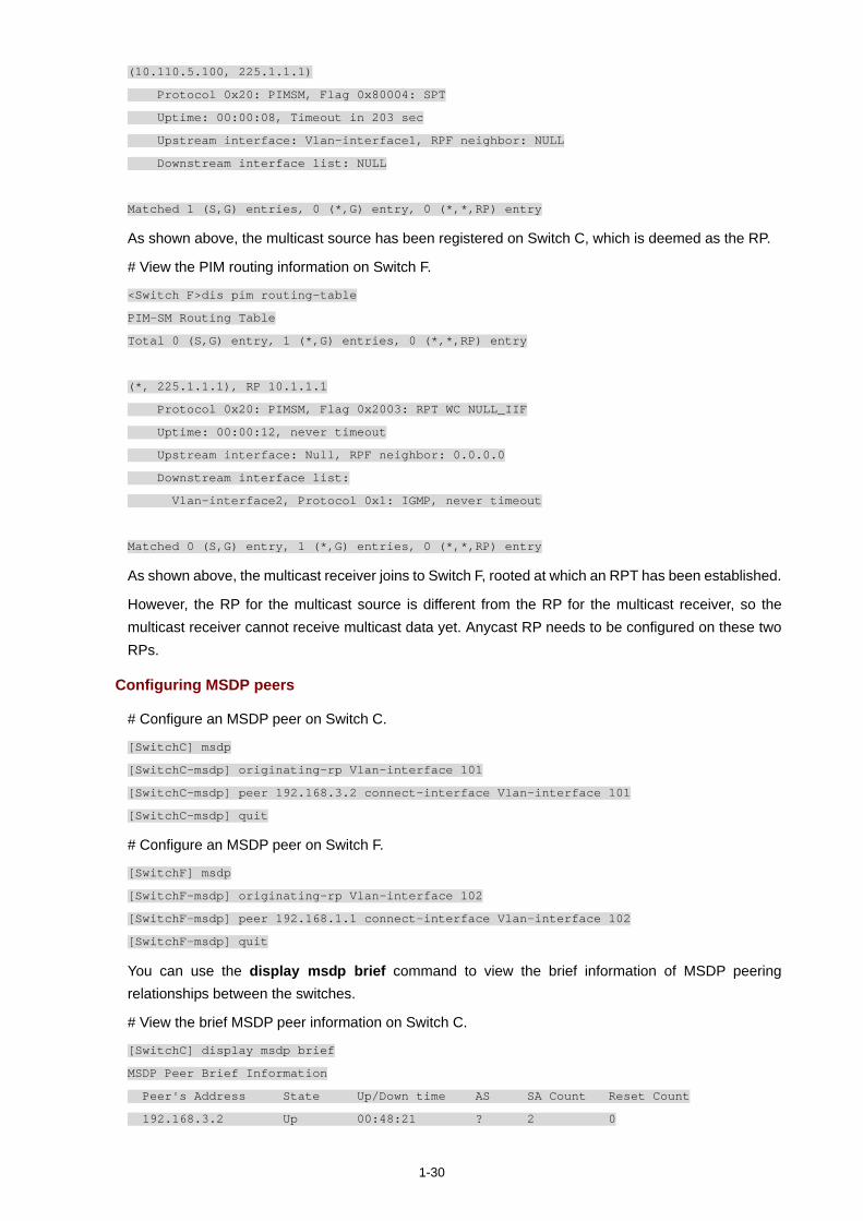
1-30
(10.110.5.100, 225.1.1.1)
Protocol 0x20: PIMSM, Flag 0x80004: SPT
Uptime: 00:00:08, Timeout in 203 sec
Upstream interface: Vlan-interface1, RPF neighbor: NULL
Downstream interface list: NULL
Matched 1 (S,G) entries, 0 (*,G) entry, 0 (*,*,RP) entry
As shown above, the multicast source has been registered on Switch C, which is deemed as the RP.
# View the PIM routing information on Switch F.
<Switch F>dis pim routing-table
PIM-SM Routing Table
Total 0 (S,G) entry, 1 (*,G) entries, 0 (*,*,RP) entry
(*, 225.1.1.1), RP 10.1.1.1
Protocol 0x20: PIMSM, Flag 0x2003: RPT WC NULL_IIF
Uptime: 00:00:12, never timeout
Upstream interface: Null, RPF neighbor: 0.0.0.0
Downstream interface list:
Vlan-interface2, Protocol 0x1: IGMP, never timeout
Matched 0 (S,G) entry, 1 (*,G) entries, 0 (*,*,RP) entry
As shown above, the multicast receiver joins to Switch F, rooted at which an RPT has been established.
However, the RP for the multicast source is different from the RP for the multicast receiver, so the multicast receiver cannot receive multicast data yet. Anycast RP needs to be configured on these two RPs.
Configuring MSDP peers
# Configure an MSDP peer on Switch C.
[SwitchC] msdp
[SwitchC-msdp] originating-rp Vlan-interface 101
[SwitchC-msdp] peer 192.168.3.2 connect-interface Vlan-interface 101
[SwitchC-msdp] quit
# Configure an MSDP peer on Switch F.
[SwitchF] msdp
[SwitchF-msdp] originating-rp Vlan-interface 102
[SwitchF-msdp] peer 192.168.1.1 connect-interface Vlan-interface 102
[SwitchF-msdp] quit
You can use the display msdp brief command to view the brief information of MSDP peering relationships between the switches.
# View the brief MSDP peer information on Switch C.
[SwitchC] display msdp brief
MSDP Peer Brief Information
Peer's Address State Up/Down time AS SA Count Reset Count
192.168.3.2 Up 00:48:21 ? 2 0
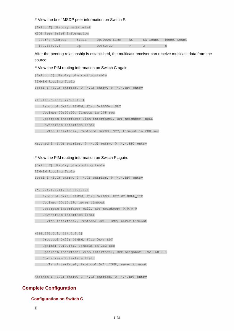
1-31
# View the brief MSDP peer information on Switch F.
[SwitchF] display msdp brief
MSDP Peer Brief Information
Peer's Address State Up/Down time AS SA Count Reset Count
192.168.1.1 Up 00:50:22 ? 2 0
After the peering relationship is established, the multicast receiver can receive multicast data from the source.
# View the PIM routing information on Switch C again.
[Switch C] display pim routing-table
PIM-SM Routing Table
Total 1 (S,G) entries, 0 (*,G) entry, 0 (*,*,RP) entry
(10.110.5.100, 225.1.1.1)
Protocol 0x20: PIMSM, Flag 0x80004: SPT
Uptime: 00:00:55, Timeout in 208 sec
Upstream interface: Vlan-interface1, RPF neighbor: NULL
Downstream interface list:
Vlan-interface2, Protocol 0x200: SPT, timeout in 200 sec
Matched 1 (S,G) entries, 0 (*,G) entry, 0 (*,*,RP) entry
# View the PIM routing information on Switch F again.
[SwitchF] display pim routing-table
PIM-SM Routing Table
Total 1 (S,G) entry, 3 (*,G) entries, 0 (*,*,RP) entry
(*, 224.1.1.1), RP 10.1.1.1
Protocol 0x20: PIMSM, Flag 0x2003: RPT WC NULL_IIF
Uptime: 00:25:26, never timeout
Upstream interface: Null, RPF neighbor: 0.0.0.0
Downstream interface list:
Vlan-interface2, Protocol 0x1: IGMP, never timeout
(192.168.3.1, 224.1.1.1)
Protocol 0x20: PIMSM, Flag 0x4: SPT
Uptime: 00:02:56, Timeout in 202 sec
Upstream interface: Vlan-interface1, RPF neighbor: 192.168.1.1
Downstream interface list:
Vlan-interface2, Protocol 0x1: IGMP, never timeout
Matched 1 (S,G) entry, 3 (*,G) entries, 0 (*,*,RP) entry
Complete Configuration
Configuration on Switch C
#
1-32
multicast routing-enable
#
interface Vlan-interface100
ip address 10.110.1.1 255.255.255.0.
pim sm
#
interface Vlan-interface101
ip address 192.168.1.1 255.255.255.0
pim sm
#
interface Vlan-interface103
ip address 10.110.1.1 255.255.255.0
pim sm
#
interface LoopBack1
ip address 3.3.3.3 255.255.255.255
pim sm
#
interface LoopBack10
ip address 10.1.1.1 255.255.255.255
pim sm
#
pim
c-bsr LoopBack1 24
c-rp LoopBack10
#
msdp
originating-rp Vlan-interface101
peer 192.168.3.2 connect-interface Vlan-interface101
#
Configuration on Switch F
#
multicast routing-enable
#
interface Vlan-interface102
ip address 192.168.3.2 255.255.255.0
pim sm
#
interface Vlan-interface200
ip address 10.110.3.1 255.255.255.0
pim sm
#
interface LoopBack1
ip address 4.4.4.4 255.255.255.255
pim sm
#
1-33
interface LoopBack10
ip address 10.1.1.1 255.255.255.255
pim sm
#
pim
c-bsr LoopBack1 24
c-rp LoopBack10
#
msdp
originating-rp Vlan-interface102
peer 192.168.1.1 connect-interface Vlan-interface102
#
Precautions
Be sure to configure a 32-bit subnet mask (255.255.255.255) for the Anycast RP address, namely configure the Anycast RP address as a host address.

i
Table of Contents
1 802.1x Configuration Guide······················································································································1-1 Configuring 802.1x Access Control·········································································································1-1
Network Diagram·····························································································································1-1 Networking and Configuration Requirements··················································································1-1 Applicable Product Matrix················································································································1-2 Configuration Procedure··················································································································1-2 Complete Configuration···················································································································1-3 Precautions······································································································································1-4
Configuring Quick EAD Deployment·······································································································1-4 Network diagram ·····························································································································1-5 Networking and Configuration Requirements··················································································1-5 Applicable Product Matrix················································································································1-5 Configuration procedure··················································································································1-6 Complete Configuration···················································································································1-6 Precautions······································································································································1-6
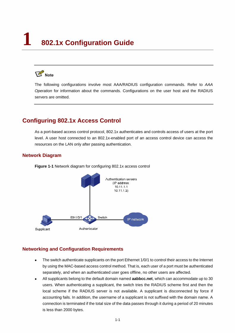
1-1
1 802.1x Configuration Guide
The following configurations involve most AAA/RADIUS configuration commands. Refer to AAA Operation for information about the commands. Configurations on the user host and the RADIUS servers are omitted.
Configuring 802.1x Access Control
As a port-based access control protocol, 802.1x authenticates and controls access of users at the port level. A user host connected to an 802.1x-enabled port of an access control device can access the resources on the LAN only after passing authentication.
Network Diagram
Figure 1-1 Network diagram for configuring 802.1x access control
Networking and Configuration Requirements
The switch authenticate supplicants on the port Ethernet 1/0/1 to control their access to the Internet by using the MAC-based access control method. That is, each user of a port must be authenticated separately, and when an authenticated user goes offline, no other users are affected.
All supplicants belong to the default domain named aabbcc.net, which can accommodate up to 30 users. When authenticating a supplicant, the switch tries the RADIUS scheme first and then the local scheme if the RADIUS server is not available. A supplicant is disconnected by force if accounting fails. In addition, the username of a supplicant is not suffixed with the domain name. A connection is terminated if the total size of the data passes through it during a period of 20 minutes is less than 2000 bytes.

1-2
The switch is connected to a server group comprising of two RADIUS servers whose IP addresses are 10.11.1.1 and 10.11.1.2 respectively. The former operates as the primary authentication server and the secondary accounting server, while the latter operates as the secondary authentication server and the primary accounting server. The shared key for authentication message exchange is name, and that for accounting message exchange is money. If the switch sends a packet to the RADIUS server but receives no response in 5 seconds, it retransmits the packet for up to 5 times. The switch sends real-time accounting packets at an interval of 15 minutes. A username is sent to the RADIUS server with the domain name truncated.
The username and password for local 802.1x authentication are localuser and localpass (in plain text) respectively. The idle disconnecting function is enabled.
Applicable Product Matrix
Product series Software version Hardware version
Switch 5500G V03.02.04 V03.03.01
All versions
Switch 5500 V03.02.03 V03.03.01
All versions
Switch 4500 V03.02.00 V03.03.00
All versions
Switch 4200G V03.02.00 All versions
Switch 4210 V03.01.00 V03.01.05
All versions
Configuration Procedure
# Enable 802.1x globally.
<Sysname> system-view
[Sysname] dot1x
# Enable 802.1x on Ethernet 1/0/1.
[Sysname] dot1x interface Ethernet 1/0/1
# Set the access control method to MAC-based. This operation can be omitted because MAC-based is the default.
[Sysname] dot1x port-method macbased interface Ethernet 1/0/1
# Create a RADIUS scheme named radius1 and enter the RADIUS scheme view.
[Sysname] radius scheme radius1
# Assign IP addresses to the primary authentication and accounting RADIUS servers.
[Sysname-radius-radius1] primary authentication 10.11.1.1
[Sysname-radius-radius1] primary accounting 10.11.1.2
# Assign IP addresses to the secondary authentication and accounting RADIUS servers.
[Sysname-radius-radius1] secondary authentication 10.11.1.2
[Sysname-radius-radius1] secondary accounting 10.11.1.1
1-3
# Set the shared key for message exchange between the switch and the RADIUS authentication server.
[Sysname -radius-radius1] key authentication name
# Set the shared key for message exchange between the switch and the RADIUS accounting server.
[Sysname-radius-radius1] key accounting money
# Set the interval and the number of packet transmission attempts for the switch to send packets to the RADIUS server.
[Sysname-radius-radius1] timer 5
[Sysname-radius-radius1] retry 5
# Set the interval for the switch to send real-time accounting packets to the RADIUS server.
[Sysname-radius-radius1] timer realtime-accounting 15
# Configure the switch to send a username without the domain name to the RADIUS server.
[Sysname-radius-radius1] user-name-format without-domain
[Sysname-radius-radius1] quit
# Create a domain named aabbcc.net and enter its view.
[Sysname] domain aabbcc.net
# Specify radius1 as the RADIUS scheme of the user domain, and the local authentication scheme as the backup scheme when the RADIUS server is not available.
[Sysname-isp-aabbcc.net] scheme radius-scheme radius1 local
# Specify the maximum number of users of the user domain to 30.
[Sysname-isp-aabbcc.net] access-limit enable 30
# Enable the idle disconnecting function and set the related parameters.
[Sysname-isp-aabbcc.net] idle-cut enable 20 2000
[Sysname-isp-aabbcc.net] quit
# Set aabbcc.net as the default user domain.
[Sysname] domain default enable aabbcc.net
# Create a local user.
[Sysname] local-user localuser
[Sysname-luser-localuser] service-type lan-access
[Sysname-luser-localuser] password simple localpass
Complete Configuration
#
domain default enable aabbcc.net
#
dot1x
#
interface Ethernet1/0/1
dot1x
#
radius scheme system
radius scheme radius1
server-type standard
1-4
primary authentication 10.11.1.1
primary accounting 10.11.1.2
secondary authentication 10.11.1.2
secondary accounting 10.11.1.1
key authentication name
key accounting money
timer realtime-accounting 15
timer response-timeout 5
retry 5
user-name-format without-domain
#
domain aabbcc.net
scheme radius-scheme radius1 local
access-limit enable 30
idle-cut enable 20 2000
domain system
#
local-user localuser
password simple localpass
service-type lan-access
#
Precautions
1) 802.1x and the maximum number of MAC addresses that a port can learn are mutually exclusive. You cannot configure both of them on a port at the same time.
2) You can neither add an 802.1x-enabled port into an aggregation group nor enable 802.1x on a port which is a member of an aggregation group.
3) When a port uses the MAC-based access control method, users are authenticated individually and when a user goes offline, no other users are affected. When a port uses the port-based access control method, once a user passes authentication, all users on the port can access the network. But if the user gets offline, the port will be disabled and will log off all the other users.
4) If you use the dot1x port-method command to change the port access method, all online users will be logged off by force.
Configuring Quick EAD Deployment
As an integrated security scheme, an endpoint admission defense (EAD) scheme can improve the overall defense capability of a network. However, EAD deployment brings much workload in actual applications. To solve this problem, you can use 802.1x functions to implement fast deployment of EAD scheme.
To address the issue, the 3Com series switches enable the user’s quick redirection to EAD client download server with 802.1x authentication, easing the work of EAD client deployment.
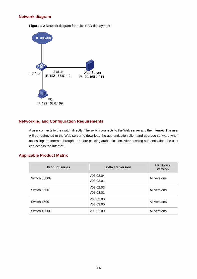
1-5
Network diagram
Figure 1-2 Network diagram for quick EAD deployment
Networking and Configuration Requirements
A user connects to the switch directly. The switch connects to the Web server and the Internet. The user will be redirected to the Web server to download the authentication client and upgrade software when accessing the Internet through IE before passing authentication. After passing authentication, the user can access the Internet.
Applicable Product Matrix
Product series Software version Hardware version
Switch 5500G V03.02.04 V03.03.01
All versions
Switch 5500 V03.02.03 V03.03.01
All versions
Switch 4500 V03.02.00 V03.03.00
All versions
Switch 4200G V03.02.00 All versions
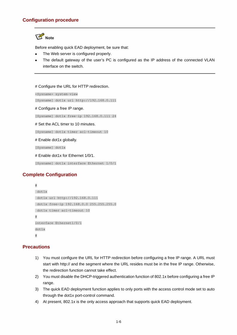
1-6
Configuration procedure
Before enabling quick EAD deployment, be sure that: The Web server is configured properly. The default gateway of the user’s PC is configured as the IP address of the connected VLAN
interface on the switch.
# Configure the URL for HTTP redirection.
<Sysname> system-view
[Sysname] dot1x url http://192.168.0.111
# Configure a free IP range.
[Sysname] dot1x free-ip 192.168.0.111 24
# Set the ACL timer to 10 minutes.
[Sysname] dot1x timer acl-timeout 10
# Enable dot1x globally.
[Sysname] dot1x
# Enable dot1x for Ethernet 1/0/1.
[Sysname] dot1x interface Ethernet 1/0/1
Complete Configuration
#
dot1x
dot1x url http://192.168.0.111
dot1x free-ip 192.168.0.0 255.255.255.0
dot1x timer acl-timeout 10
#
interface Ethernet1/0/1
dot1x
#
Precautions
1) You must configure the URL for HTTP redirection before configuring a free IP range. A URL must start with http:// and the segment where the URL resides must be in the free IP range. Otherwise, the redirection function cannot take effect.
2) You must disable the DHCP-triggered authentication function of 802.1x before configuring a free IP range.
3) The quick EAD deployment function applies to only ports with the access control mode set to auto through the dot1x port-control command.
4) At present, 802.1x is the only access approach that supports quick EAD deployment.

1-7
5) Currently, the quick EAD deployment function does not support port security. The configured free IP range cannot take effect if you enable port security.
i
Table of Contents
1 AAA Configuration Guide ·························································································································1-1 Configuring RADIUS Authentication for Telnet Users ············································································1-1
Network Diagram·····························································································································1-1 Networking and Configuration Requirements··················································································1-1 Applicable Product Matrix················································································································1-2 Configuration Procedure··················································································································1-2 Complete Configuration···················································································································1-2 Precautions······································································································································1-3
Configuring Dynamic VLAN Assignment with RADIUS Authentication ··················································1-3 Network Diagram·····························································································································1-3 Networking and Configuration Requirements··················································································1-4 Applicable Product Matrix················································································································1-4 Configuration Procedure··················································································································1-4 Complete Configuration···················································································································1-5 Precautions······································································································································1-6
Configuring Local Authentication for Telnet Users ·················································································1-6 Network Diagram·····························································································································1-6 Networking and Configuration Requirements··················································································1-6 Applicable Product Matrix················································································································1-6 Configuration Procedure··················································································································1-6 Complete Configuration···················································································································1-7 Precautions······································································································································1-7
Configuring HWTACACS Authentication for Telnet Users ·····································································1-7 Network Diagram·····························································································································1-8 Networking and Configuration Requirements··················································································1-8 Applicable Product Matrix················································································································1-8 Configuration Procedure··················································································································1-8 Complete Configuration···················································································································1-9 Precautions······································································································································1-9
Configuring EAD ·····································································································································1-9 Network Diagram···························································································································1-10 Networking and Configuration Requirements················································································1-10 Applicable Product Matrix··············································································································1-10 Configuration Procedure················································································································1-10 Complete Configuration·················································································································1-11 Precautions····································································································································1-11
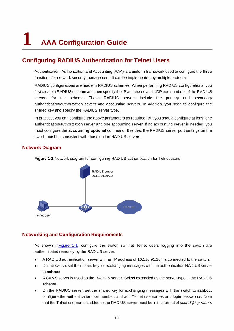
1-1
1 AAA Configuration Guide
Configuring RADIUS Authentication for Telnet Users
Authentication, Authorization and Accounting (AAA) is a uniform framework used to configure the three functions for network security management. It can be implemented by multiple protocols.
RADIUS configurations are made in RADIUS schemes. When performing RADIUS configurations, you first create a RADIUS scheme and then specify the IP addresses and UDP port numbers of the RADIUS servers for the scheme. These RADIUS servers include the primary and secondary authentication/authorization severs and accounting servers. In addition, you need to configure the shared key and specify the RADIUS server type.
In practice, you can configure the above parameters as required. But you should configure at least one authentication/authorization server and one accounting server. If no accounting server is needed, you must configure the accounting optional command. Besides, the RADIUS server port settings on the switch must be consistent with those on the RADIUS servers.
Network Diagram
Figure 1-1 Network diagram for configuring RADIUS authentication for Telnet users
Internet
Telnet user
RADIUS server10.110.91.164/16
Networking and Configuration Requirements
As shown inFigure 1-1, configure the switch so that Telnet users logging into the switch are authenticated remotely by the RADIUS server.
A RADIUS authentication server with an IP address of 10.110.91.164 is connected to the switch. On the switch, set the shared key for exchanging messages with the authentication RADIUS server
to aabbcc. A CAMS server is used as the RADIUS server. Select extended as the server-type in the RADIUS
scheme. On the RADIUS server, set the shared key for exchanging messages with the switch to aabbcc,
configure the authentication port number, and add Telnet usernames and login passwords. Note that the Telnet usernames added to the RADIUS server must be in the format of userid@isp-name.
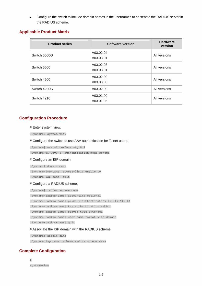
1-2
Configure the switch to include domain names in the usernames to be sent to the RADIUS server in the RADIUS scheme.
Applicable Product Matrix
Product series Software version Hardware version
Switch 5500G V03.02.04 V03.03.01
All versions
Switch 5500 V03.02.03 V03.03.01
All versions
Switch 4500 V03.02.00 V03.03.00
All versions
Switch 4200G V03.02.00 All versions
Switch 4210 V03.01.00 V03.01.05
All versions
Configuration Procedure
# Enter system view.
<Sysname> system-view
# Configure the switch to use AAA authentication for Telnet users.
[Sysname] user-interface vty 0 4
[Sysname-ui-vty0-4] authentication-mode scheme
# Configure an ISP domain.
[Sysname] domain cams
[Sysname-isp-cams] access-limit enable 10
[Sysname-isp-cams] quit
# Configure a RADIUS scheme.
[Sysname] radius scheme cams
[Sysname-radius-cams] accounting optional
[Sysname-radius-cams] primary authentication 10.110.91.164
[Sysname-radius-cams] key authentication aabbcc
[Sysname-radius-cams] server-type extended
[Sysname-radius-cams] user-name-format with-domain
[Sysname-radius-cams] quit
# Associate the ISP domain with the RADIUS scheme.
[Sysname] domain cams
[Sysname-isp-cams] scheme radius-scheme cams
Complete Configuration
#
system-view
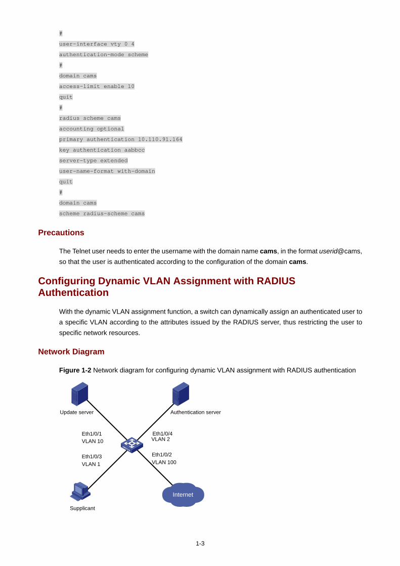
1-3
#
user-interface vty 0 4
authentication-mode scheme
#
domain cams
access-limit enable 10
quit
#
radius scheme cams
accounting optional
primary authentication 10.110.91.164
key authentication aabbcc
server-type extended
user-name-format with-domain
quit
#
domain cams
scheme radius-scheme cams
Precautions
The Telnet user needs to enter the username with the domain name cams, in the format userid@cams, so that the user is authenticated according to the configuration of the domain cams.
Configuring Dynamic VLAN Assignment with RADIUS Authentication
With the dynamic VLAN assignment function, a switch can dynamically assign an authenticated user to a specific VLAN according to the attributes issued by the RADIUS server, thus restricting the user to specific network resources.
Network Diagram
Figure 1-2 Network diagram for configuring dynamic VLAN assignment with RADIUS authentication
Internet
Supplicant
Authentication serverUpdate server
VLAN 10Eth1/0/1
VLAN 1Eth1/0/3
VLAN 2Eth1/0/4
VLAN 100Eth1/0/2
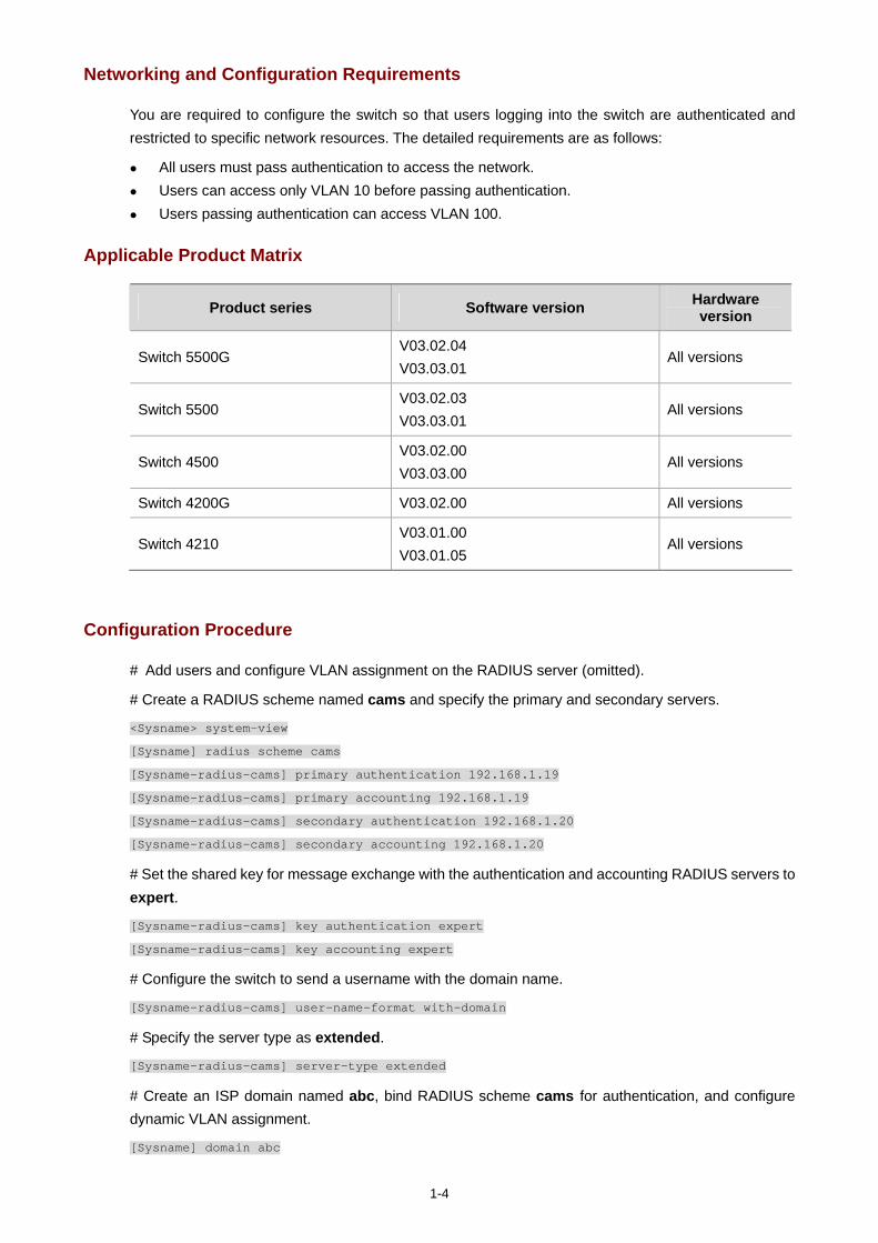
1-4
Networking and Configuration Requirements
You are required to configure the switch so that users logging into the switch are authenticated and restricted to specific network resources. The detailed requirements are as follows:
All users must pass authentication to access the network. Users can access only VLAN 10 before passing authentication. Users passing authentication can access VLAN 100.
Applicable Product Matrix
Product series Software version Hardware version
Switch 5500G V03.02.04 V03.03.01
All versions
Switch 5500 V03.02.03 V03.03.01
All versions
Switch 4500 V03.02.00 V03.03.00
All versions
Switch 4200G V03.02.00 All versions
Switch 4210 V03.01.00 V03.01.05
All versions
Configuration Procedure
# Add users and configure VLAN assignment on the RADIUS server (omitted).
# Create a RADIUS scheme named cams and specify the primary and secondary servers.
<Sysname> system-view
[Sysname] radius scheme cams
[Sysname-radius-cams] primary authentication 192.168.1.19
[Sysname-radius-cams] primary accounting 192.168.1.19
[Sysname-radius-cams] secondary authentication 192.168.1.20
[Sysname-radius-cams] secondary accounting 192.168.1.20
# Set the shared key for message exchange with the authentication and accounting RADIUS servers to expert.
[Sysname-radius-cams] key authentication expert
[Sysname-radius-cams] key accounting expert
# Configure the switch to send a username with the domain name.
[Sysname-radius-cams] user-name-format with-domain
# Specify the server type as extended.
[Sysname-radius-cams] server-type extended
# Create an ISP domain named abc, bind RADIUS scheme cams for authentication, and configure dynamic VLAN assignment.
[Sysname] domain abc
1-5
[Sysname-isp-abc] radius-scheme cams
[Sysname-isp-abc] vlan-assignment-mode integer
[Sysname-isp-abc] quit
# Configure the ISP domain abc as the default ISP domain.
[Sysname] domain default enable abc
# Enable guest VLAN on the port.
[Sysname] interface Ethernet 1/0/3
[Sysname-Ethernet1/0/3] dot1x port-method portbased
[Sysname-Ehternet1/0/3] dot1x guest-vlan 10
# Enabled 802.1x.
[Sysname] dot1x
# Enable 802.1x in interface view.
[Sysname] interface Ethernet 1/0/3
[Sysname-Ethernet1/0/3] dot1x
Complete Configuration
#
system-view
radius scheme cams
primary authentication 192.168.1.19
primary accounting 192.168.1.19
secondary authentication 192.168.1.20
secondary accounting 192.168.1.20
key authentication expert
key accounting expert
user-name-format with-domain
server-type extended
#
domain abc
radius-scheme cams
vlan-assignment-mode integer
quit
#
domain default enable abc
#
interface Ethernet 1/0/3
dot1x port-method portbased
dot1x guest-vlan 10
#
dot1x
#
interface Ethernet 1/0/3
dot1x
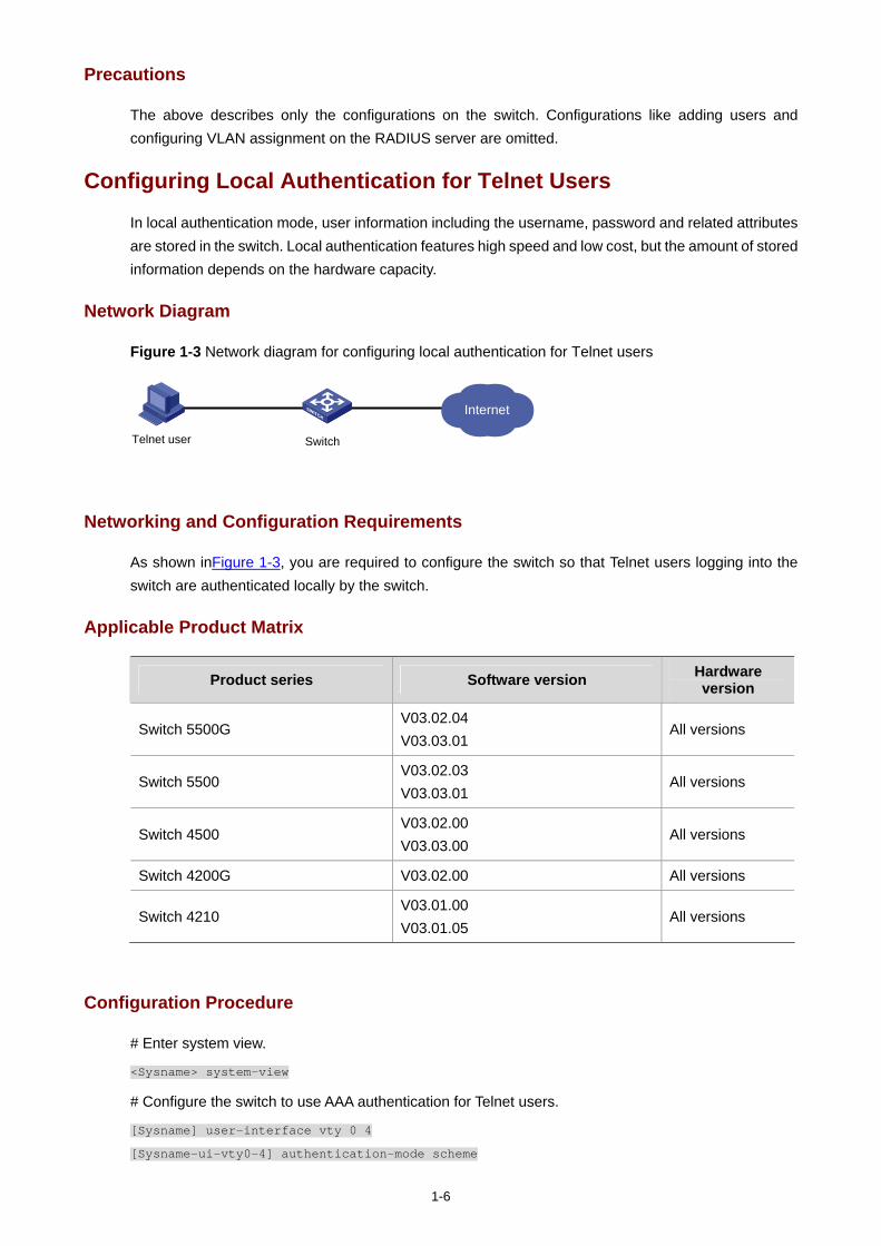
1-6
Precautions
The above describes only the configurations on the switch. Configurations like adding users and configuring VLAN assignment on the RADIUS server are omitted.
Configuring Local Authentication for Telnet Users
In local authentication mode, user information including the username, password and related attributes are stored in the switch. Local authentication features high speed and low cost, but the amount of stored information depends on the hardware capacity.
Network Diagram
Figure 1-3 Network diagram for configuring local authentication for Telnet users
Internet
SwitchTelnet user
Networking and Configuration Requirements
As shown inFigure 1-3, you are required to configure the switch so that Telnet users logging into the switch are authenticated locally by the switch.
Applicable Product Matrix
Product series Software version Hardware version
Switch 5500G V03.02.04 V03.03.01
All versions
Switch 5500 V03.02.03 V03.03.01
All versions
Switch 4500 V03.02.00 V03.03.00
All versions
Switch 4200G V03.02.00 All versions
Switch 4210 V03.01.00 V03.01.05
All versions
Configuration Procedure
# Enter system view.
<Sysname> system-view
# Configure the switch to use AAA authentication for Telnet users.
[Sysname] user-interface vty 0 4
[Sysname-ui-vty0-4] authentication-mode scheme
1-7
[Sysname-ui-vty0-4] quit
# Configure a local user named telnet.
[Sysname] local-user telnet
[Sysname-luser-telnet] service-type telnet
[Sysname-luser-telnet] password simple aabbcc
[Sysname-luser-telnet] attribute idle-cut 300 access-limit 5
[Sysname] domain system
[Sysname-isp-system] scheme local
Complete Configuration
#
system-view
#
user-interface vty 0 4
authentication-mode scheme
quit
#
local-user telnet
service-type telnet
password simple aabbcc
attribute idle-cut 300 access-limit 5
domain system
scheme local
Precautions
The Telnet user needs to enter the username with the domain name system (that is, telnet@system), so that the user is authenticated according to the configuration of the system domain.
The configurations of local authentication for FTP users are similar to those for Telnet users.
Configuring HWTACACS Authentication for Telnet Users
Huawei Terminal Access Controller Access Control System (HWTACACS) is an enhanced security protocol based on TACACS (RFC 1492). Similar to the RADIUS protocol, it adopts the client/server model and implements AAA for multiple types of users through communicating with TACACS servers.
Compared with RADIUS, HWTACACS provides more reliable transmission and encryption, and therefore is more suitable for security control.
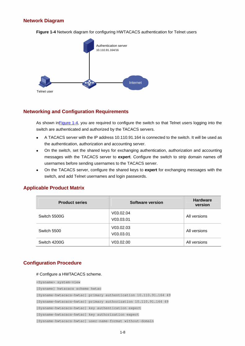
1-8
Network Diagram
Figure 1-4 Network diagram for configuring HWTACACS authentication for Telnet users
Internet
Telnet user
Authentication server10.110.91.164/16
Networking and Configuration Requirements
As shown inFigure 1-4, you are required to configure the switch so that Telnet users logging into the switch are authenticated and authorized by the TACACS servers.
A TACACS server with the IP address 10.110.91.164 is connected to the switch. It will be used as the authentication, authorization and accounting server.
On the switch, set the shared keys for exchanging authentication, authorization and accounting messages with the TACACS server to expert. Configure the switch to strip domain names off usernames before sending usernames to the TACACS server.
On the TACACS server, configure the shared keys to expert for exchanging messages with the switch, and add Telnet usernames and login passwords.
Applicable Product Matrix
Product series Software version Hardware version
Switch 5500G V03.02.04 V03.03.01
All versions
Switch 5500 V03.02.03 V03.03.01
All versions
Switch 4200G V03.02.00 All versions
Configuration Procedure
# Configure a HWTACACS scheme.
<Sysname> system-view
[Sysname] hwtacacs scheme hwtac
[Sysname-hwtacacs-hwtac] primary authentication 10.110.91.164 49
[Sysname-hwtacacs-hwtac] primary authorization 10.110.91.164 49
[Sysname-hwtacacs-hwtac] key authentication expert
[Sysname-hwtacacs-hwtac] key authorization expert
[Sysname-hwtacacs-hwtac] user-name-format without-domain
1-9
[Sysname-hwtacacs-hwtac] quit
# Configure domain hwtacacs to use HWTACACS scheme hwtac.
[Sysname] domain hwtacacs
[Sysname-isp-hwtacacs] scheme hwtacacs-scheme hwtac
[Sysname-isp-hwtacacs] accounting optional
Complete Configuration
#
system-view
hwtacacs scheme hwtac
primary authentication 10.110.91.164 49
primary authorization 10.110.91.164 49
key authentication expert
key authorization expert
user-name-format without-domain
quit
#
domain hwtacacs
scheme hwtacacs-scheme hwtac
accounting optional
Precautions
The above describes only the configuration of the HWTACACS scheme on the switch. The configuration of Telnet users on the HWTACACS server is omitted.
Configuring EAD
Endpoint Admission Defense (EAD) is an attack defense solution. By controlling access of terminals, it enhances the active defense capability of network endpoints and prevents viruses and worms from spreading on the network, thus securing the entire network.
With the cooperation of the switch, AAA sever, security policy server and security client, EAD is able to evaluate the security compliance of network endpoints and dynamically control their access rights.
With EAD, a switch verifies the validity of the session control packets it receives according to the source IP addresses of the packets:
It regards only packets from the authentication and security policy servers valid. It assigns ACLs according to session control packets, thus controlling the access rights of users
dynamically.
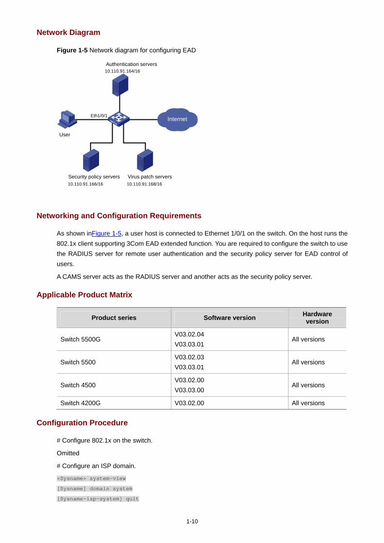
1-10
Network Diagram
Figure 1-5 Network diagram for configuring EAD
Eth1/0/1 Internet
User
Security policy servers10.110.91.166/16
Virus patch servers10.110.91.168/16
Authentication servers10.110.91.164/16
Networking and Configuration Requirements
As shown inFigure 1-5, a user host is connected to Ethernet 1/0/1 on the switch. On the host runs the 802.1x client supporting 3Com EAD extended function. You are required to configure the switch to use the RADIUS server for remote user authentication and the security policy server for EAD control of users.
A CAMS server acts as the RADIUS server and another acts as the security policy server.
Applicable Product Matrix
Product series Software version Hardware version
Switch 5500G V03.02.04 V03.03.01
All versions
Switch 5500 V03.02.03 V03.03.01
All versions
Switch 4500 V03.02.00 V03.03.00
All versions
Switch 4200G V03.02.00 All versions
Configuration Procedure
# Configure 802.1x on the switch.
Omitted
# Configure an ISP domain.
<Sysname> system-view
[Sysname] domain system
[Sysname-isp-system] quit
1-11
# Configure a RADIUS scheme.
[Sysname] radius scheme cams
[Sysname-radius-cams] primary authentication 10.110.91.164 1812
[Sysname-radius-cams] accounting optional
[Sysname-radius-cams] key authentication expert
[Sysname-radius-cams] server-type extended
# Specify the IP address of the security policy server.
[Sysname-radius-cams] security-policy-server 10.110.91.166
# Associate the ISP domain with the RADIUS scheme.
[Sysname-radius-cams] quit
[Sysname] domain system
[Sysname-isp-system] radius-scheme cams
Complete Configuration
#
system-view
domain system
quit
#
radius scheme cams
primary authentication 10.110.91.164 1812
accounting optional
key authentication expert
server-type extended
security-policy-server 10.110.91.166
#
quit
domain system
radius-scheme cams
Precautions
To support all extended functions of CAMS, you are recommended to configure the 802.1x authentication method as EAP and the RADIUS scheme server type as extended on the switch.

i
Table of Contents
1 MAC Authentication Configuration Guide ······························································································1-1 Configuring MAC Authentication·············································································································1-1
Network Diagram·····························································································································1-1 Networking and Configuration Requirements··················································································1-1 Applicable Product Matrix················································································································1-1 Configuration Procedure··················································································································1-2 Complete Configuration···················································································································1-2 Precautions······································································································································1-3
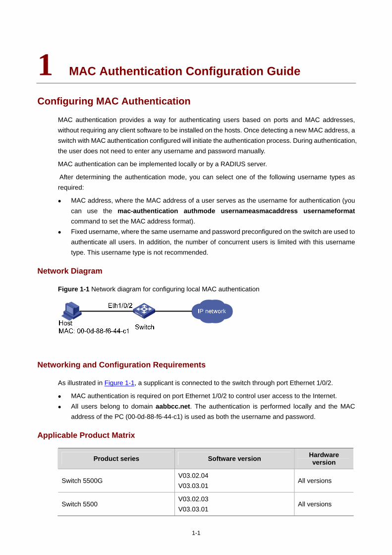
1-1
1 MAC Authentication Configuration Guide
Configuring MAC Authentication
MAC authentication provides a way for authenticating users based on ports and MAC addresses, without requiring any client software to be installed on the hosts. Once detecting a new MAC address, a switch with MAC authentication configured will initiate the authentication process. During authentication, the user does not need to enter any username and password manually.
MAC authentication can be implemented locally or by a RADIUS server.
After determining the authentication mode, you can select one of the following username types as required:
MAC address, where the MAC address of a user serves as the username for authentication (you can use the mac-authentication authmode usernameasmacaddress usernameformat command to set the MAC address format).
Fixed username, where the same username and password preconfigured on the switch are used to authenticate all users. In addition, the number of concurrent users is limited with this username type. This username type is not recommended.
Network Diagram
Figure 1-1 Network diagram for configuring local MAC authentication
Networking and Configuration Requirements
As illustrated in Figure 1-1, a supplicant is connected to the switch through port Ethernet 1/0/2.
MAC authentication is required on port Ethernet 1/0/2 to control user access to the Internet. All users belong to domain aabbcc.net. The authentication is performed locally and the MAC
address of the PC (00-0d-88-f6-44-c1) is used as both the username and password.
Applicable Product Matrix
Product series Software version Hardware version
Switch 5500G V03.02.04 V03.03.01
All versions
Switch 5500 V03.02.03 V03.03.01
All versions
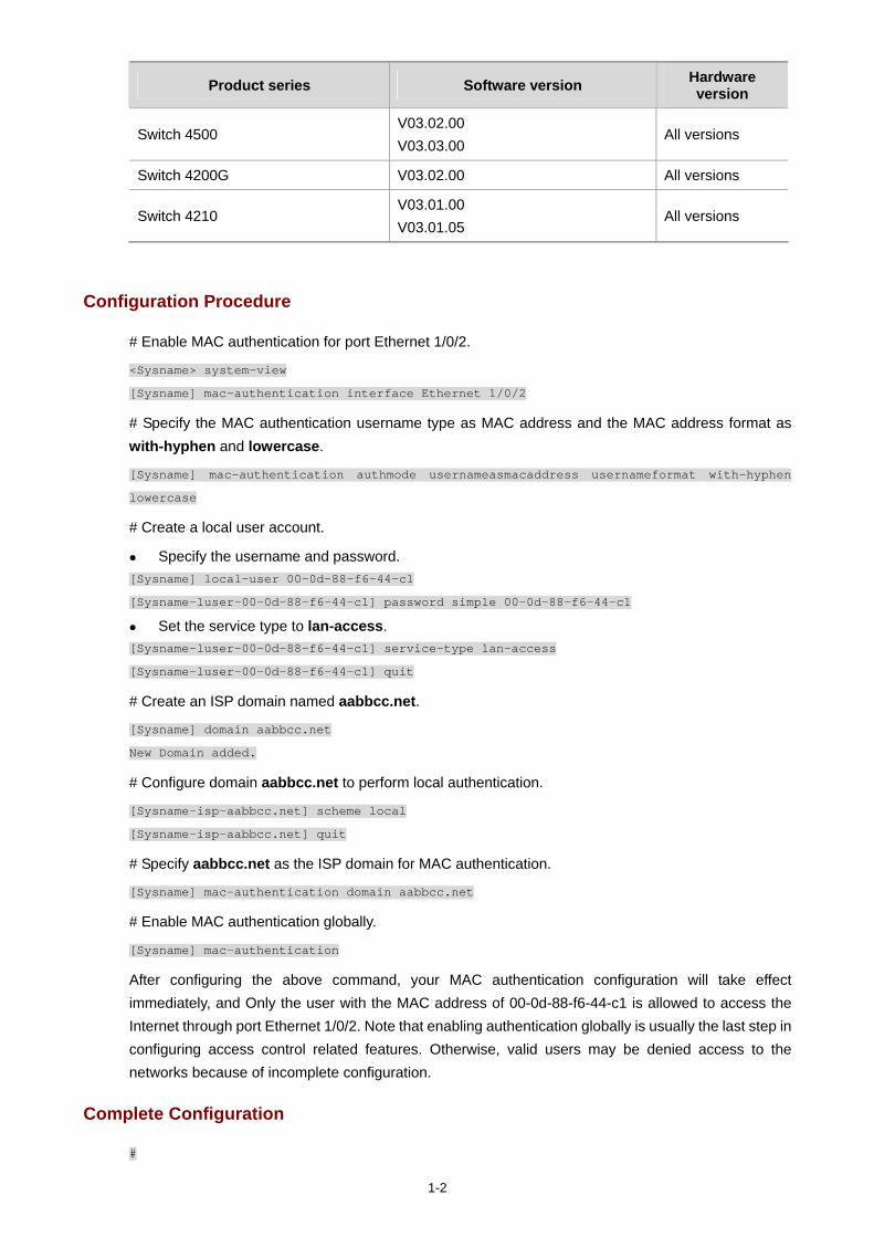
1-2
Product series Software version Hardware version
Switch 4500 V03.02.00 V03.03.00
All versions
Switch 4200G V03.02.00 All versions
Switch 4210 V03.01.00 V03.01.05
All versions
Configuration Procedure
# Enable MAC authentication for port Ethernet 1/0/2.
<Sysname> system-view
[Sysname] mac-authentication interface Ethernet 1/0/2
# Specify the MAC authentication username type as MAC address and the MAC address format as with-hyphen and lowercase.
[Sysname] mac-authentication authmode usernameasmacaddress usernameformat with-hyphen
lowercase
# Create a local user account.
Specify the username and password. [Sysname] local-user 00-0d-88-f6-44-c1
[Sysname-luser-00-0d-88-f6-44-c1] password simple 00-0d-88-f6-44-c1
Set the service type to lan-access. [Sysname-luser-00-0d-88-f6-44-c1] service-type lan-access
[Sysname-luser-00-0d-88-f6-44-c1] quit
# Create an ISP domain named aabbcc.net.
[Sysname] domain aabbcc.net
New Domain added.
# Configure domain aabbcc.net to perform local authentication.
[Sysname-isp-aabbcc.net] scheme local
[Sysname-isp-aabbcc.net] quit
# Specify aabbcc.net as the ISP domain for MAC authentication.
[Sysname] mac-authentication domain aabbcc.net
# Enable MAC authentication globally.
[Sysname] mac-authentication
After configuring the above command, your MAC authentication configuration will take effect immediately, and Only the user with the MAC address of 00-0d-88-f6-44-c1 is allowed to access the Internet through port Ethernet 1/0/2. Note that enabling authentication globally is usually the last step in configuring access control related features. Otherwise, valid users may be denied access to the networks because of incomplete configuration.
Complete Configuration
#
1-3
domain default enable aabbcc.net
#
MAC-authentication
MAC-authentication domain aabbcc.net
MAC-authentication authmode usernameasmacaddress usernameformat with-hyphen #
domain aabbcc.net
#
local-user 00-0d-88-f6-44-c1
password simple 00-0d-88-f6-44-c1
service-type lan-access
#
Precautions
You cannot configure the maximum number of MAC addresses that can be learnt on a MAC authentication enabled port, or enable MAC authentication on a port that is configured with the maximum number of MAC addresses that can be learnt.
You cannot configure port security on a MAC authentication enabled port, or enable MAC authentication on a port that is configured with port security.
i
Table of Contents
1 VRRP Configuring Guide ··························································································································1-1 Single VRRP Group Configuration··········································································································1-1
Network Diagram·····························································································································1-1 Networking and Configuration Requirements··················································································1-1 Applicable Product Matrix················································································································1-2 Configuration Procedure··················································································································1-2 Complete Configuration···················································································································1-3 Precautions······································································································································1-4
Multiple VRRP Groups Configuration ·····································································································1-4 Network Diagram·····························································································································1-4 Networking and Configuration Requirements··················································································1-4 Applicable Product Matrix················································································································1-5 Configuration Procedure··················································································································1-5 Complete Configuration···················································································································1-5 Precautions······································································································································1-6
VRRP Interface Tracking ························································································································1-6 Network Diagram·····························································································································1-7 Networking and Configuration Requirements··················································································1-7 Applicable Product Matrix················································································································1-7 Configuration Procedure··················································································································1-7 Complete Configuration···················································································································1-8 Precautions······································································································································1-9
VRRP Port Tracking································································································································1-9 Network Diagram·····························································································································1-9 Networking and Configuration Requirements················································································1-10 Applicable Product Matrix··············································································································1-10 Configuration Procedure················································································································1-10 Complete Configuration·················································································································1-11 Precautions····································································································································1-11
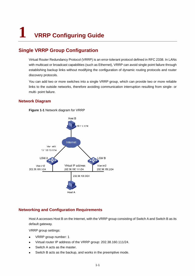
1-1
1 VRRP Configuring Guide
Single VRRP Group Configuration
Virtual Router Redundancy Protocol (VRRP) is an error-tolerant protocol defined in RFC 2338. In LANs with multicast or broadcast capabilities (such as Ethernet), VRRP can avoid single point failure through establishing backup links without modifying the configuration of dynamic routing protocols and router discovery protocols.
You can add two or more switches into a single VRRP group, which can provide two or more reliable links to the outside networks, therefore avoiding communication interruption resulting from single- or multi- point failure.
Network Diagram
Figure 1-1 Network diagram for VRRP
Networking and Configuration Requirements
Host A accesses Host B on the Internet, with the VRRP group consisting of Switch A and Switch B as its default gateway.
VRRP group settings:
VRRP group number: 1 Virtual router IP address of the VRRP group: 202.38.160.111/24. Switch A acts as the master. Switch B acts as the backup, and works in the preemptive mode.
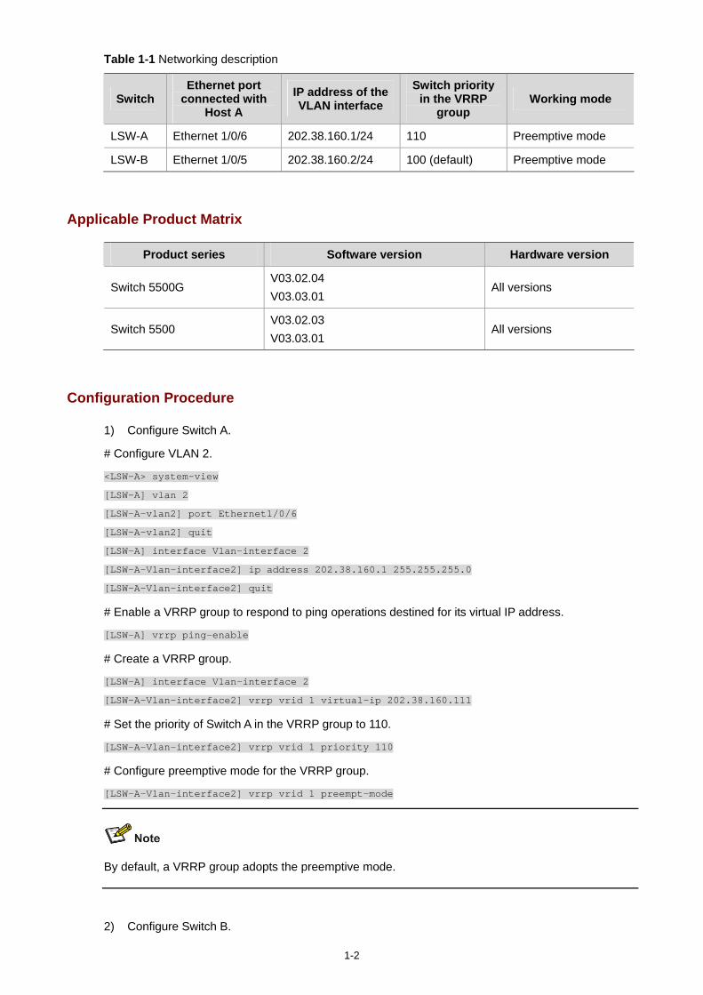
1-2
Table 1-1 Networking description
Switch Ethernet port
connected with Host A
IP address of the VLAN interface
Switch priority in the VRRP
group Working mode
LSW-A Ethernet 1/0/6 202.38.160.1/24 110 Preemptive mode
LSW-B Ethernet 1/0/5 202.38.160.2/24 100 (default) Preemptive mode
Applicable Product Matrix
Product series Software version Hardware version
Switch 5500G V03.02.04 V03.03.01
All versions
Switch 5500 V03.02.03 V03.03.01
All versions
Configuration Procedure
1) Configure Switch A.
# Configure VLAN 2.
<LSW-A> system-view
[LSW-A] vlan 2
[LSW-A-vlan2] port Ethernet1/0/6
[LSW-A-vlan2] quit
[LSW-A] interface Vlan-interface 2
[LSW-A-Vlan-interface2] ip address 202.38.160.1 255.255.255.0
[LSW-A-Vlan-interface2] quit
# Enable a VRRP group to respond to ping operations destined for its virtual IP address.
[LSW-A] vrrp ping-enable
# Create a VRRP group.
[LSW-A] interface Vlan-interface 2
[LSW-A-Vlan-interface2] vrrp vrid 1 virtual-ip 202.38.160.111
# Set the priority of Switch A in the VRRP group to 110.
[LSW-A-Vlan-interface2] vrrp vrid 1 priority 110
# Configure preemptive mode for the VRRP group.
[LSW-A-Vlan-interface2] vrrp vrid 1 preempt-mode
By default, a VRRP group adopts the preemptive mode.
2) Configure Switch B.
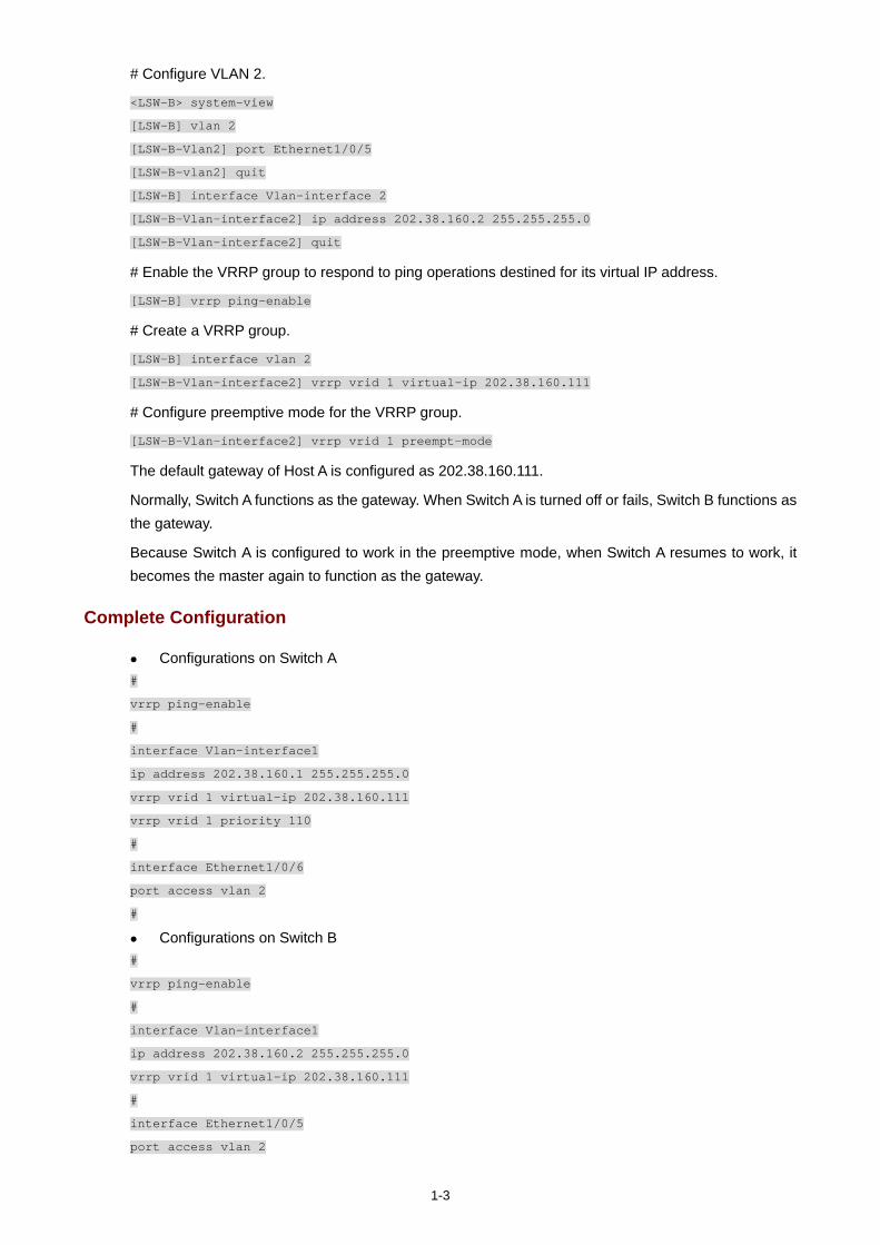
1-3
# Configure VLAN 2.
<LSW-B> system-view
[LSW-B] vlan 2
[LSW-B-Vlan2] port Ethernet1/0/5
[LSW-B-vlan2] quit
[LSW-B] interface Vlan-interface 2
[LSW-B-Vlan-interface2] ip address 202.38.160.2 255.255.255.0
[LSW-B-Vlan-interface2] quit
# Enable the VRRP group to respond to ping operations destined for its virtual IP address.
[LSW-B] vrrp ping-enable
# Create a VRRP group.
[LSW-B] interface vlan 2
[LSW-B-Vlan-interface2] vrrp vrid 1 virtual-ip 202.38.160.111
# Configure preemptive mode for the VRRP group.
[LSW-B-Vlan-interface2] vrrp vrid 1 preempt-mode
The default gateway of Host A is configured as 202.38.160.111.
Normally, Switch A functions as the gateway. When Switch A is turned off or fails, Switch B functions as the gateway.
Because Switch A is configured to work in the preemptive mode, when Switch A resumes to work, it becomes the master again to function as the gateway.
Complete Configuration
Configurations on Switch A #
vrrp ping-enable
#
interface Vlan-interface1
ip address 202.38.160.1 255.255.255.0
vrrp vrid 1 virtual-ip 202.38.160.111
vrrp vrid 1 priority 110
#
interface Ethernet1/0/6
port access vlan 2
#
Configurations on Switch B #
vrrp ping-enable
#
interface Vlan-interface1
ip address 202.38.160.2 255.255.255.0
vrrp vrid 1 virtual-ip 202.38.160.111
#
interface Ethernet1/0/5
port access vlan 2
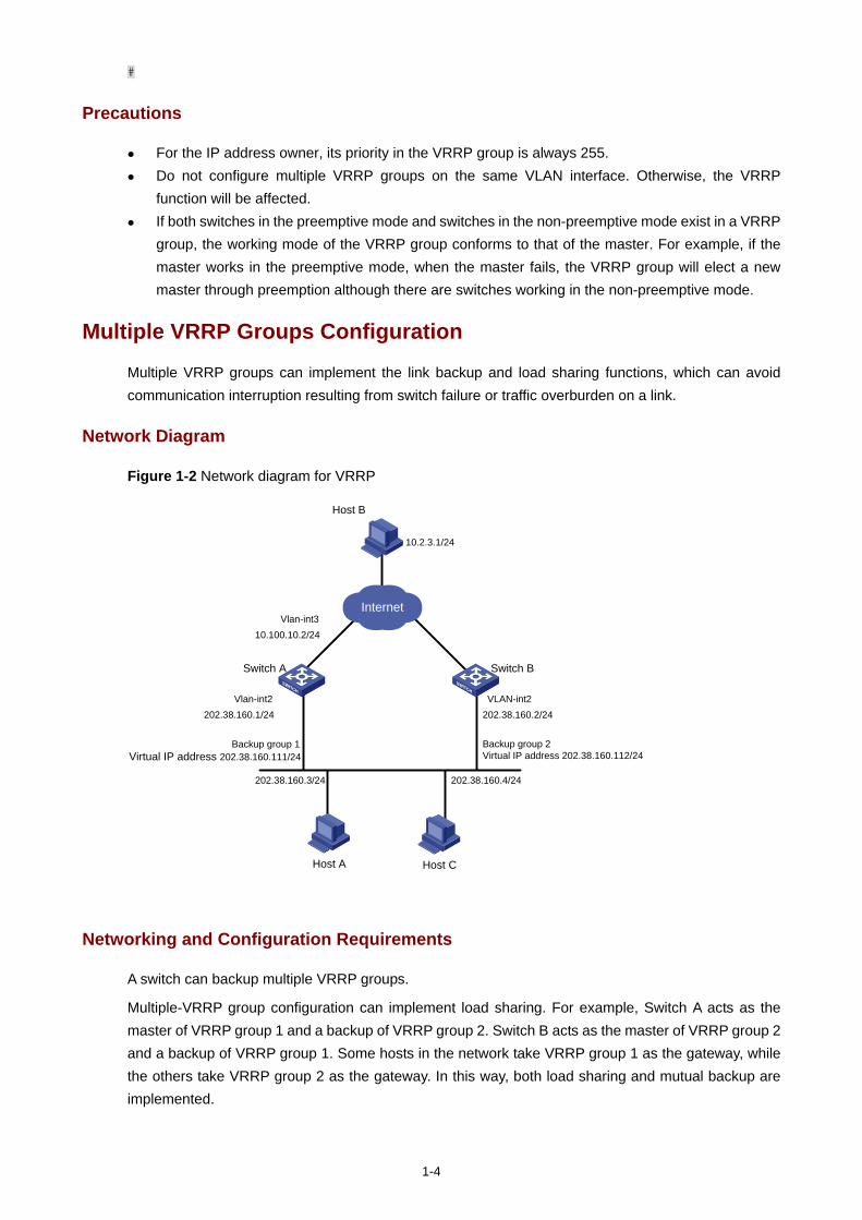
1-4
#
Precautions
For the IP address owner, its priority in the VRRP group is always 255. Do not configure multiple VRRP groups on the same VLAN interface. Otherwise, the VRRP
function will be affected. If both switches in the preemptive mode and switches in the non-preemptive mode exist in a VRRP
group, the working mode of the VRRP group conforms to that of the master. For example, if the master works in the preemptive mode, when the master fails, the VRRP group will elect a new master through preemption although there are switches working in the non-preemptive mode.
Multiple VRRP Groups Configuration
Multiple VRRP groups can implement the link backup and load sharing functions, which can avoid communication interruption resulting from switch failure or traffic overburden on a link.
Network Diagram
Figure 1-2 Network diagram for VRRP
Switch A
Host C
Host B
Switch B
Vlan-int310.100.10.2/24
Vlan-int2202.38.160.1/24
VLAN-int2202.38.160.2/24
202.38.160.3/24
10.2.3.1/24
Host A
202.38.160.4/24
Internet
Backup group 1Virtual IP address 202.38.160.111/24
Backup group 2Virtual IP address 202.38.160.112/24
Networking and Configuration Requirements
A switch can backup multiple VRRP groups.
Multiple-VRRP group configuration can implement load sharing. For example, Switch A acts as the master of VRRP group 1 and a backup of VRRP group 2. Switch B acts as the master of VRRP group 2 and a backup of VRRP group 1. Some hosts in the network take VRRP group 1 as the gateway, while the others take VRRP group 2 as the gateway. In this way, both load sharing and mutual backup are implemented.
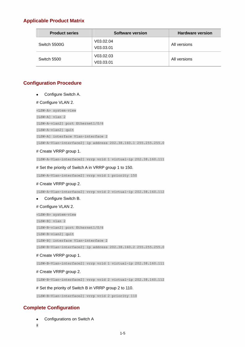
1-5
Applicable Product Matrix
Product series Software version Hardware version
Switch 5500G V03.02.04 V03.03.01
All versions
Switch 5500 V03.02.03 V03.03.01
All versions
Configuration Procedure
Configure Switch A.
# Configure VLAN 2.
<LSW-A> system-view
[LSW-A] vlan 2
[LSW-A-vlan2] port Ethernet1/0/6
[LSW-A-vlan2] quit
[LSW-A] interface Vlan-interface 2
[LSW-A-Vlan-interface2] ip address 202.38.160.1 255.255.255.0
# Create VRRP group 1.
[LSW-A-Vlan-interface2] vrrp vrid 1 virtual-ip 202.38.160.111
# Set the priority of Switch A in VRRP group 1 to 150.
[LSW-A-Vlan-interface2] vrrp vrid 1 priority 150
# Create VRRP group 2.
[LSW-A-Vlan-interface2] vrrp vrid 2 virtual-ip 202.38.160.112
Configure Switch B.
# Configure VLAN 2.
<LSW-B> system-view
[LSW-B] vlan 2
[LSW-B-vlan2] port Ethernet1/0/6
[LSW-B-vlan2] quit
[LSW-B] interface Vlan-interface 2
[LSW-B-Vlan-interface2] ip address 202.38.160.2 255.255.255.0
# Create VRRP group 1.
[LSW-B-Vlan-interface2] vrrp vrid 1 virtual-ip 202.38.160.111
# Create VRRP group 2.
[LSW-B-Vlan-interface2] vrrp vrid 2 virtual-ip 202.38.160.112
# Set the priority of Switch B in VRRP group 2 to 110.
[LSW-B-Vlan-interface2] vrrp vrid 2 priority 110
Complete Configuration
Configurations on Switch A #
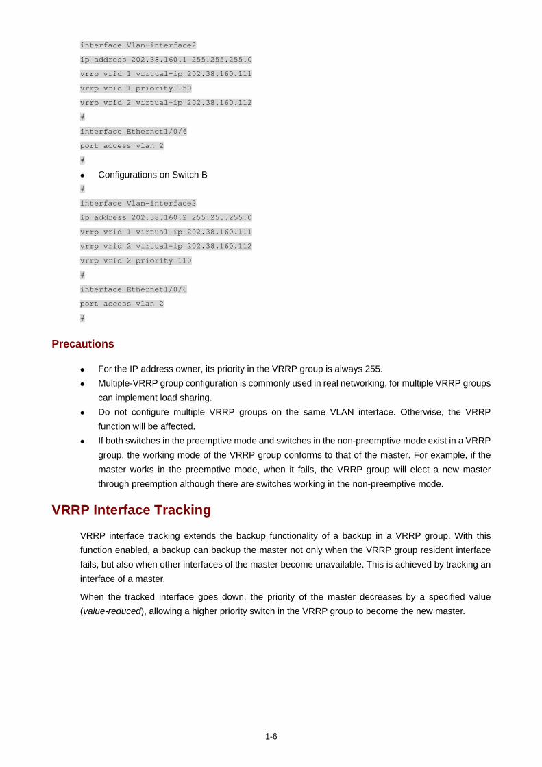
1-6
interface Vlan-interface2
ip address 202.38.160.1 255.255.255.0
vrrp vrid 1 virtual-ip 202.38.160.111
vrrp vrid 1 priority 150
vrrp vrid 2 virtual-ip 202.38.160.112
#
interface Ethernet1/0/6
port access vlan 2
#
Configurations on Switch B #
interface Vlan-interface2
ip address 202.38.160.2 255.255.255.0
vrrp vrid 1 virtual-ip 202.38.160.111
vrrp vrid 2 virtual-ip 202.38.160.112
vrrp vrid 2 priority 110
#
interface Ethernet1/0/6
port access vlan 2
#
Precautions
For the IP address owner, its priority in the VRRP group is always 255. Multiple-VRRP group configuration is commonly used in real networking, for multiple VRRP groups
can implement load sharing. Do not configure multiple VRRP groups on the same VLAN interface. Otherwise, the VRRP
function will be affected. If both switches in the preemptive mode and switches in the non-preemptive mode exist in a VRRP
group, the working mode of the VRRP group conforms to that of the master. For example, if the master works in the preemptive mode, when it fails, the VRRP group will elect a new master through preemption although there are switches working in the non-preemptive mode.
VRRP Interface Tracking
VRRP interface tracking extends the backup functionality of a backup in a VRRP group. With this function enabled, a backup can backup the master not only when the VRRP group resident interface fails, but also when other interfaces of the master become unavailable. This is achieved by tracking an interface of a master.
When the tracked interface goes down, the priority of the master decreases by a specified value (value-reduced), allowing a higher priority switch in the VRRP group to become the new master.
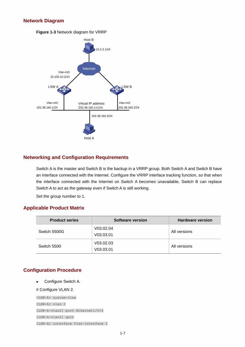
1-7
Network Diagram
Figure 1-3 Network diagram for VRRP
LSW A
Host B
LSW B
Vlan-int310.100.10.2/24
Vlan-int2202.38.160.1/24
Vlan-int2202.38.160.2/24
202.38.160.3/24
10.2.3.1/24
Host A
Internet
Virtual IP address 202.38.160.111/24
Networking and Configuration Requirements
Switch A is the master and Switch B is the backup in a VRRP group. Both Switch A and Switch B have an interface connected with the Internet. Configure the VRRP interface tracking function, so that when the interface connected with the Internet on Switch A becomes unavailable, Switch B can replace Switch A to act as the gateway even if Switch A is still working.
Set the group number to 1.
Applicable Product Matrix
Product series Software version Hardware version
Switch 5500G V03.02.04 V03.03.01
All versions
Switch 5500 V03.02.03 V03.03.01
All versions
Configuration Procedure
Configure Switch A.
# Configure VLAN 2.
<LSW-A> system-view
[LSW-A] vlan 2
[LSW-A-vlan2] port Ethernet1/0/6
[LSW-A-vlan2] quit
[LSW-A] interface Vlan-interface 2
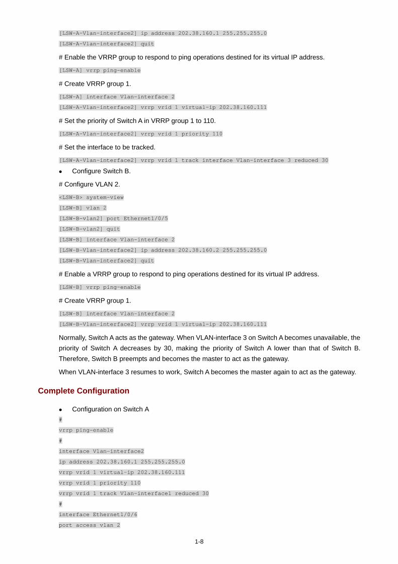
1-8
[LSW-A-Vlan-interface2] ip address 202.38.160.1 255.255.255.0
[LSW-A-Vlan-interface2] quit
# Enable the VRRP group to respond to ping operations destined for its virtual IP address.
[LSW-A] vrrp ping-enable
# Create VRRP group 1.
[LSW-A] interface Vlan-interface 2
[LSW-A-Vlan-interface2] vrrp vrid 1 virtual-ip 202.38.160.111
# Set the priority of Switch A in VRRP group 1 to 110.
[LSW-A-Vlan-interface2] vrrp vrid 1 priority 110
# Set the interface to be tracked.
[LSW-A-Vlan-interface2] vrrp vrid 1 track interface Vlan-interface 3 reduced 30
Configure Switch B.
# Configure VLAN 2.
<LSW-B> system-view
[LSW-B] vlan 2
[LSW-B-vlan2] port Ethernet1/0/5
[LSW-B-vlan2] quit
[LSW-B] interface Vlan-interface 2
[LSW-B-Vlan-interface2] ip address 202.38.160.2 255.255.255.0
[LSW-B-Vlan-interface2] quit
# Enable a VRRP group to respond to ping operations destined for its virtual IP address.
[LSW-B] vrrp ping-enable
# Create VRRP group 1.
[LSW-B] interface Vlan-interface 2
[LSW-B-Vlan-interface2] vrrp vrid 1 virtual-ip 202.38.160.111
Normally, Switch A acts as the gateway. When VLAN-interface 3 on Switch A becomes unavailable, the priority of Switch A decreases by 30, making the priority of Switch A lower than that of Switch B. Therefore, Switch B preempts and becomes the master to act as the gateway.
When VLAN-interface 3 resumes to work, Switch A becomes the master again to act as the gateway.
Complete Configuration
Configuration on Switch A #
vrrp ping-enable
#
interface Vlan-interface2
ip address 202.38.160.1 255.255.255.0
vrrp vrid 1 virtual-ip 202.38.160.111
vrrp vrid 1 priority 110
vrrp vrid 1 track Vlan-interface1 reduced 30
#
interface Ethernet1/0/6
port access vlan 2
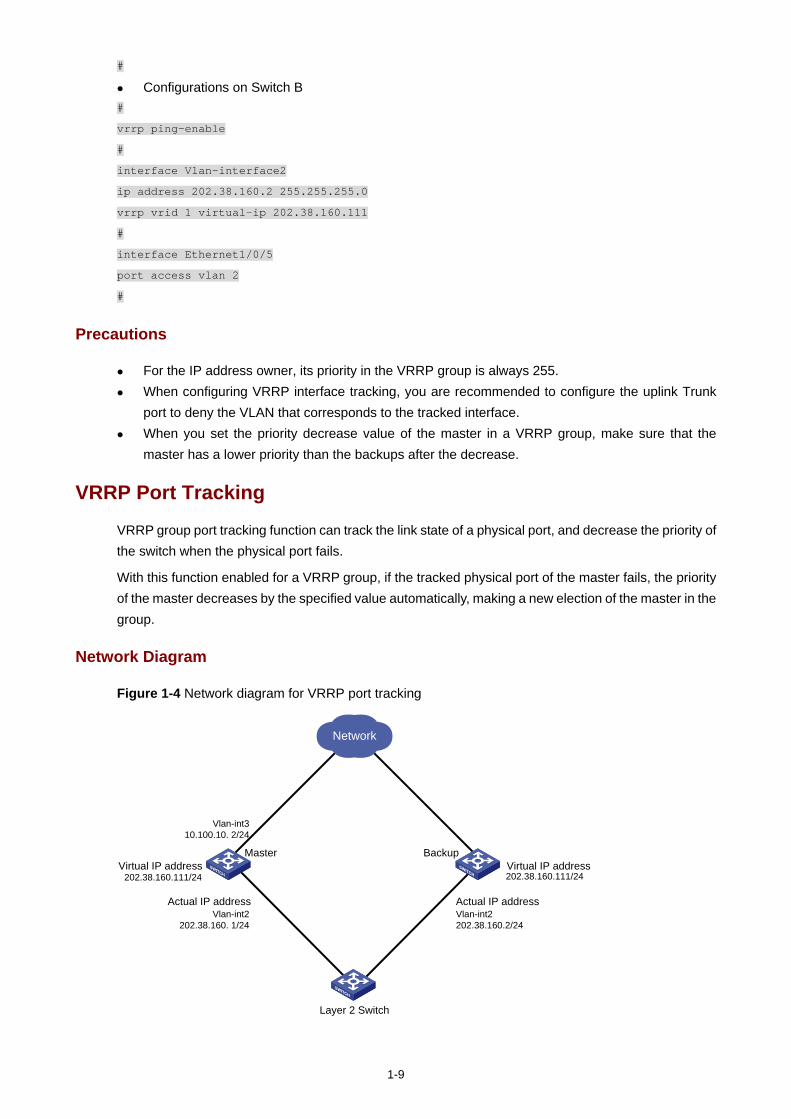
1-9
#
Configurations on Switch B #
vrrp ping-enable
#
interface Vlan-interface2
ip address 202.38.160.2 255.255.255.0
vrrp vrid 1 virtual-ip 202.38.160.111
#
interface Ethernet1/0/5
port access vlan 2
#
Precautions
For the IP address owner, its priority in the VRRP group is always 255. When configuring VRRP interface tracking, you are recommended to configure the uplink Trunk
port to deny the VLAN that corresponds to the tracked interface. When you set the priority decrease value of the master in a VRRP group, make sure that the
master has a lower priority than the backups after the decrease.
VRRP Port Tracking
VRRP group port tracking function can track the link state of a physical port, and decrease the priority of the switch when the physical port fails.
With this function enabled for a VRRP group, if the tracked physical port of the master fails, the priority of the master decreases by the specified value automatically, making a new election of the master in the group.
Network Diagram
Figure 1-4 Network diagram for VRRP port tracking
Vlan-int310.100.10. 2/24
Master
Network
Layer 2 Switch
Backup
Actual IP address
Virtual IP address 202.38.160.111/24
Virtual IP address 202.38.160.111/24
Vlan-int2202.38.160. 1/24
Actual IP address Vlan-int2202.38.160.2/24
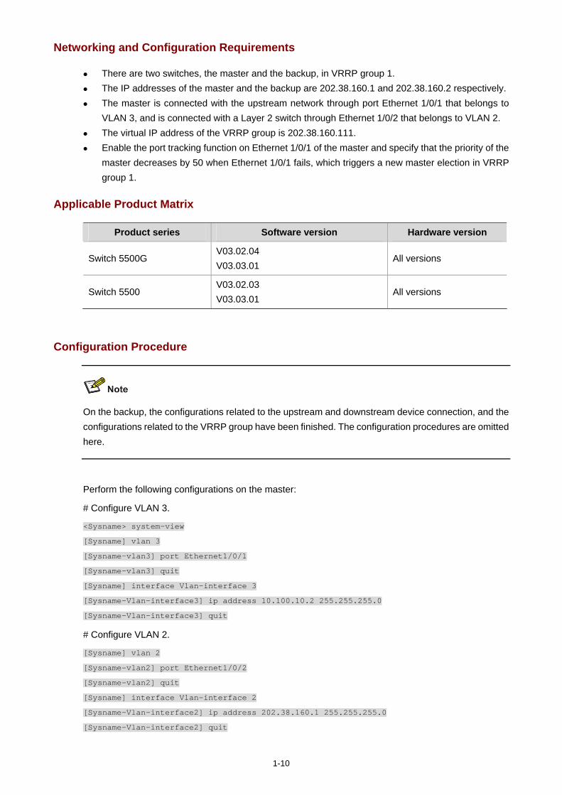
1-10
Networking and Configuration Requirements
There are two switches, the master and the backup, in VRRP group 1. The IP addresses of the master and the backup are 202.38.160.1 and 202.38.160.2 respectively. The master is connected with the upstream network through port Ethernet 1/0/1 that belongs to
VLAN 3, and is connected with a Layer 2 switch through Ethernet 1/0/2 that belongs to VLAN 2. The virtual IP address of the VRRP group is 202.38.160.111. Enable the port tracking function on Ethernet 1/0/1 of the master and specify that the priority of the
master decreases by 50 when Ethernet 1/0/1 fails, which triggers a new master election in VRRP group 1.
Applicable Product Matrix
Product series Software version Hardware version
Switch 5500G V03.02.04 V03.03.01
All versions
Switch 5500 V03.02.03 V03.03.01
All versions
Configuration Procedure
On the backup, the configurations related to the upstream and downstream device connection, and the configurations related to the VRRP group have been finished. The configuration procedures are omitted here.
Perform the following configurations on the master:
# Configure VLAN 3.
<Sysname> system-view
[Sysname] vlan 3
[Sysname-vlan3] port Ethernet1/0/1
[Sysname-vlan3] quit
[Sysname] interface Vlan-interface 3
[Sysname-Vlan-interface3] ip address 10.100.10.2 255.255.255.0
[Sysname-Vlan-interface3] quit
# Configure VLAN 2.
[Sysname] vlan 2
[Sysname-vlan2] port Ethernet1/0/2
[Sysname-vlan2] quit
[Sysname] interface Vlan-interface 2
[Sysname-Vlan-interface2] ip address 202.38.160.1 255.255.255.0
[Sysname-Vlan-interface2] quit
1-11
# Create VRRP group 1.
[Sysname] interface Vlan-interface 2
[Sysname-Vlan-interface2] vrrp vrid 1 virtual-ip 202.38.160.111
[Sysname-Vlan-interface2] quit
# Enter port view of Ethernet 1/0/1 and enable the VRRP port tracking function.
[Sysname] interface Ethernet1/0/1
[Sysname-Ethernet1/0/1] vrrp Vlan-interface 2 vrid 1 track reduced 50
Complete Configuration
On the master:
#
interface Vlan-interface2
ip address 202.38.160.1 255.255.255.0
vrrp vrid 1 virtual-ip 202.38.160.111
#
interface Vlan-interface3
ip address 10.100.10.2 255.255.255.0
#
interface Ethernet1/0/1
port access vlan 3
vrrp Vlan-interface 2 vrid 1 track reduced 50
#
interface Ethernet1/0/2
port access vlan 2
#
Precautions
For the IP address owner, its priority in the VRRP group is always 255. When you set the priority decrease value of the master in a VRRP group, make sure that the
master has a lower priority than the backups after the decrease.
i
Table of Contents
1 ARP Configuration Guide ·························································································································1-1 ARP Attack Detection and Packet Rate Limit Configuration Example ···················································1-1
Network Diagram·····························································································································1-1 Networking and Configuration Requirements··················································································1-1 Applicable Product Matrix················································································································1-1 Configuration procedure··················································································································1-2 Complete Configuration···················································································································1-2 Precautions······································································································································1-3
Proxy ARP Configuration Example ·········································································································1-3 Network diagram ·····························································································································1-3 Network requirements ·····················································································································1-3 Applicable Product Matrix················································································································1-4 Configuration procedure··················································································································1-4 Complete Configuration···················································································································1-4 Precautions······································································································································1-4
Proxy ARP Configuration in Port Isolation Application ···········································································1-5 Network diagram ·····························································································································1-5 Network requirements ·····················································································································1-5 Applicable Product Matrix················································································································1-5 Configuration procedure··················································································································1-5 Complete Configuration···················································································································1-6 Precautions······································································································································1-6
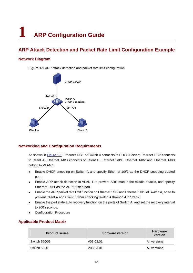
1-1
1 ARP Configuration Guide
ARP Attack Detection and Packet Rate Limit Configuration Example
Network Diagram
Figure 1-1 ARP attack detection and packet rate limit configuration
Networking and Configuration Requirements
As shown in Figure 1-1, Ethernet 1/0/1 of Switch A connects to DHCP Server; Ethernet 1/0/2 connects to Client A, Ethernet 1/0/3 connects to Client B. Ethernet 1/0/1, Ethernet 1/0/2 and Ethernet 1/0/3 belong to VLAN 1.
Enable DHCP snooping on Switch A and specify Ethernet 1/0/1 as the DHCP snooping trusted port.
Enable ARP attack detection in VLAN 1 to prevent ARP man-in-the-middle attacks, and specify Ethernet 1/0/1 as the ARP trusted port.
Enable the ARP packet rate limit function on Ethernet 1/0/2 and Ethernet 1/0/3 of Switch A, so as to prevent Client A and Client B from attacking Switch A through ARP traffic.
Enable the port state auto recovery function on the ports of Switch A, and set the recovery interval to 200 seconds.
Configuration Procedure
Applicable Product Matrix
Product series Software version Hardware version
Switch 5500G V03.03.01 All versions
Switch 5500 V03.03.01 All versions
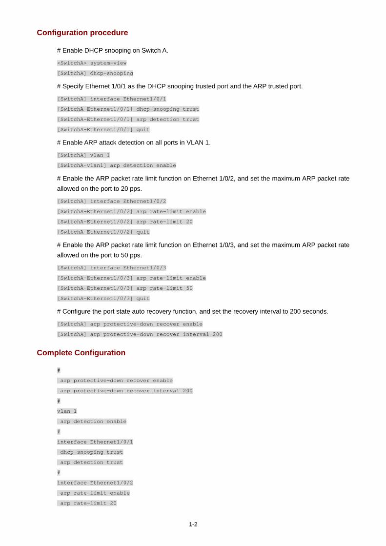
1-2
Configuration procedure
# Enable DHCP snooping on Switch A.
<SwitchA> system-view
[SwitchA] dhcp-snooping
# Specify Ethernet 1/0/1 as the DHCP snooping trusted port and the ARP trusted port.
[SwitchA] interface Ethernet1/0/1
[SwitchA-Ethernet1/0/1] dhcp-snooping trust
[SwitchA-Ethernet1/0/1] arp detection trust
[SwitchA-Ethernet1/0/1] quit
# Enable ARP attack detection on all ports in VLAN 1.
[SwitchA] vlan 1
[SwitchA-vlan1] arp detection enable
# Enable the ARP packet rate limit function on Ethernet 1/0/2, and set the maximum ARP packet rate allowed on the port to 20 pps.
[SwitchA] interface Ethernet1/0/2
[SwitchA-Ethernet1/0/2] arp rate-limit enable
[SwitchA-Ethernet1/0/2] arp rate-limit 20
[SwitchA-Ethernet1/0/2] quit
# Enable the ARP packet rate limit function on Ethernet 1/0/3, and set the maximum ARP packet rate allowed on the port to 50 pps.
[SwitchA] interface Ethernet1/0/3
[SwitchA-Ethernet1/0/3] arp rate-limit enable
[SwitchA-Ethernet1/0/3] arp rate-limit 50
[SwitchA-Ethernet1/0/3] quit
# Configure the port state auto recovery function, and set the recovery interval to 200 seconds.
[SwitchA] arp protective-down recover enable
[SwitchA] arp protective-down recover interval 200
Complete Configuration
#
arp protective-down recover enable
arp protective-down recover interval 200
#
vlan 1
arp detection enable
#
interface Ethernet1/0/1
dhcp-snooping trust
arp detection trust
#
interface Ethernet1/0/2
arp rate-limit enable
arp rate-limit 20

1-3
#
interface Ethernet1/0/3
arp rate-limit enable
arp rate-limit 50
#
dhcp-snooping
#
Precautions
You need to enable DHCP snooping and configure DHCP snooping trusted ports on the switch before configuring the ARP attack detection function.
You need to enable the port state auto-recovery feature before you can configure the port state auto-recovery interval.
Generally, the uplink port of a switch is configured as a trusted port. You are not recommended to configure ARP attack detection or ARP packet rate limit function on
the ports of a fabric or an aggregation group.
Proxy ARP Configuration Example
Network diagram
Figure 1-2 Network diagram for proxy ARP
Vlan-int1192.168.10.99/24
192.168.10.100/160000.0c94.36aa
192.168.20.200/160000.0c94.36dd
Switch
Subnet B
Subnet A
Host A Host B
Host C Host D
Vlan-int2192.168.20.99/24
Network requirements
Host A belongs to VLAN 1, and the IP address of Host A is 192.168.10.100/16, Host D belongs to VLAN 2, and the IP address of Host D is 192.168.20.100/16.
The IP address of VLAN-interface 1 is 192.168.10.99/24, and that of VLAN-interface 2 is 192.168.20.99/24.
Enable proxy ARP on VLAN-interface 1 and VLAN-interface 2 to realize the communication between Host A and Host D.
1-4
Applicable Product Matrix
Product series Software version Hardware version
Switch 5500G V03.03.01 All versions
Switch 5500 V03.03.01 All versions
Configuration procedure
# Configure the IP address of VLAN-interface 1 to be 192.168.10.99/24, and enable proxy ARP on VLAN-interface 1.
<Switch> system-view
[Switch] interface vlan-interface 1
[Switch-Vlan-interface1] ip address 192.168.10.99 255.255.255.0
[Switch-Vlan-interface1] arp proxy enable
[Switch-Vlan-interface1] quit
# Configure the IP address of VLAN-interface 2 to be 192.168.20.99/24, and enable proxy ARP on VLAN-interface 2.
[Switch] interface vlan-interface 2
[Switch-Vlan-interface2] ip address 192.168.20.99 255.255.255.0
[Switch-Vlan-interface2] arp proxy enable
[Switch-Vlan-interface2] quit
Complete Configuration
#
interface Vlan-interface1
arp proxy enable
ip address 192.168.10.99 255.255.255.0
#
interface Vlan-interface2
arp proxy enable
ip address 192.168.20.99 255.255.255.0
#
Precautions
None
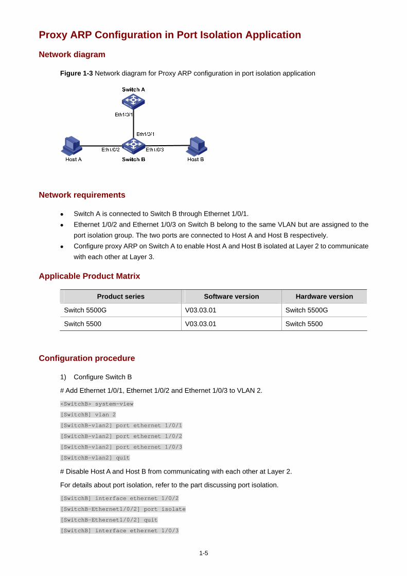
1-5
Proxy ARP Configuration in Port Isolation Application
Network diagram
Figure 1-3 Network diagram for Proxy ARP configuration in port isolation application
Network requirements
Switch A is connected to Switch B through Ethernet 1/0/1. Ethernet 1/0/2 and Ethernet 1/0/3 on Switch B belong to the same VLAN but are assigned to the
port isolation group. The two ports are connected to Host A and Host B respectively. Configure proxy ARP on Switch A to enable Host A and Host B isolated at Layer 2 to communicate
with each other at Layer 3.
Applicable Product Matrix
Product series Software version Hardware version
Switch 5500G V03.03.01 Switch 5500G
Switch 5500 V03.03.01 Switch 5500
Configuration procedure
1) Configure Switch B
# Add Ethernet 1/0/1, Ethernet 1/0/2 and Ethernet 1/0/3 to VLAN 2.
<SwitchB> system-view
[SwitchB] vlan 2
[SwitchB-vlan2] port ethernet 1/0/1
[SwitchB-vlan2] port ethernet 1/0/2
[SwitchB-vlan2] port ethernet 1/0/3
[SwitchB-vlan2] quit
# Disable Host A and Host B from communicating with each other at Layer 2.
For details about port isolation, refer to the part discussing port isolation.
[SwitchB] interface ethernet 1/0/2
[SwitchB-Ethernet1/0/2] port isolate
[SwitchB-Ethernet1/0/2] quit
[SwitchB] interface ethernet 1/0/3
1-6
[SwitchB-Ethernet1/0/3] port isolate
[SwitchB-Ethernet1/0/3] quit
2) Configure Switch A
# Configure the IP address of VLAN-interface 2 to be 192.168.10.100/24.
[SwitchA] vlan 2
[SwitchA-vlan2] port ethernet 1/0/1
[SwitchA-vlan2] quit
[SwitchA] interface vlan-interface 2
[SwitchA-Vlan-interface2] ip address 192.168.10.100 255.255.0.0
# Configure proxy ARP on VLAN-interface 2, enabling Host A and Host B to communicate at Layer 3.
[SwitchA-Vlan-interface2] arp proxy enable
[SwitchA-Vlan-interface2] quit
Complete Configuration
1) Configuration on Switch B #
vlan 2
#
interface Ethernet1/0/1
port access vlan 2
#
interface Ethernet1/0/2
port access vlan 2
port isolate
#
interface Ethernet1/0/3
port access vlan 2
port isolate
#
2) Configuration on Switch A #
vlan 2
#
interface Vlan-interface2
arp proxy enable
ip address 192.168.10.100 255.255.0.0
#
interface Ethernet1/0/1
port access vlan 2
#
Precautions
For details about port isolation, refer to the part discussing port isolation.
i
Table of Contents
1 DHCP Configuration Guide·······················································································································1-1 DHCP Server Global Address Pool Configuration Guide ·······································································1-1
Network Diagram·····························································································································1-1 Networking and Configuration Requirements··················································································1-1 Applicable Product Matrix················································································································1-2 Configuration Procedure··················································································································1-2 Complete Configuration···················································································································1-3 Precautions······································································································································1-3
DHCP Server Interface Address Pool Configuration Guide····································································1-4 Network Diagram·····························································································································1-4 Networking and Configuration Requirements··················································································1-4 Applicable Product Matrix················································································································1-4 Configuration Procedure··················································································································1-4 Complete Configuration···················································································································1-5 Precautions······································································································································1-5
DHCP Relay Agent Configuration Guide ································································································1-5 Network Diagram·····························································································································1-6 Networking and Configuration Requirements··················································································1-6 Applicable Product Matrix················································································································1-6 Configuration Procedure··················································································································1-6 Complete Configuration···················································································································1-7 Precautions······································································································································1-7
DHCP Snooping Configuration Guide·····································································································1-7 Network Diagram·····························································································································1-8 Networking and Configuration Requirements··················································································1-8 Applicable Product Matrix················································································································1-8 Configuration Procedure··················································································································1-8 Complete Configuration···················································································································1-9 Precautions······································································································································1-9
DHCP Snooping Option 82 Configuration Guide····················································································1-9 Network Diagram·····························································································································1-9 Networking and Configuration Requirements················································································1-10 Applicable Product Matrix··············································································································1-10 Configuration Procedure················································································································1-10 Complete Configuration·················································································································1-12 Precautions····································································································································1-12
DHCP Accounting Configuration Guide································································································1-12 Network Diagram···························································································································1-13 Networking and Configuration Requirements················································································1-13 Applicable Product Matrix··············································································································1-13 Configuration Procedure················································································································1-13 Complete Configuration·················································································································1-14 Precautions····································································································································1-15

ii
DHCP Client Configuration Guide·········································································································1-15 Network Diagram···························································································································1-15 Networking and Configuration Requirements················································································1-15 Applicable Product Matrix··············································································································1-15 Configuration Procedure················································································································1-15 Complete Configuration·················································································································1-16 Precautions····································································································································1-16
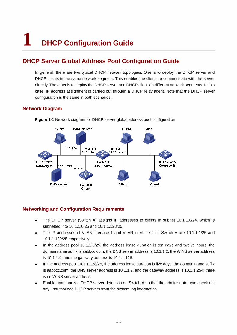
1-1
1 DHCP Configuration Guide
DHCP Server Global Address Pool Configuration Guide
In general, there are two typical DHCP network topologies. One is to deploy the DHCP server and DHCP clients in the same network segment. This enables the clients to communicate with the server directly. The other is to deploy the DHCP server and DHCP clients in different network segments. In this case, IP address assignment is carried out through a DHCP relay agent. Note that the DHCP server configuration is the same in both scenarios.
Network Diagram
Figure 1-1 Network diagram for DHCP server global address pool configuration
Networking and Configuration Requirements
The DHCP server (Switch A) assigns IP addresses to clients in subnet 10.1.1.0/24, which is subnetted into 10.1.1.0/25 and 10.1.1.128/25.
The IP addresses of VLAN-interface 1 and VLAN-interface 2 on Switch A are 10.1.1.1/25 and 10.1.1.129/25 respectively.
In the address pool 10.1.1.0/25, the address lease duration is ten days and twelve hours, the domain name suffix is aabbcc.com, the DNS server address is 10.1.1.2, the WINS server address is 10.1.1.4, and the gateway address is 10.1.1.126.
In the address pool 10.1.1.128/25, the address lease duration is five days, the domain name suffix is aabbcc.com, the DNS server address is 10.1.1.2, and the gateway address is 10.1.1.254; there is no WINS server address.
Enable unauthorized DHCP server detection on Switch A so that the administrator can check out any unauthorized DHCP servers from the system log information.
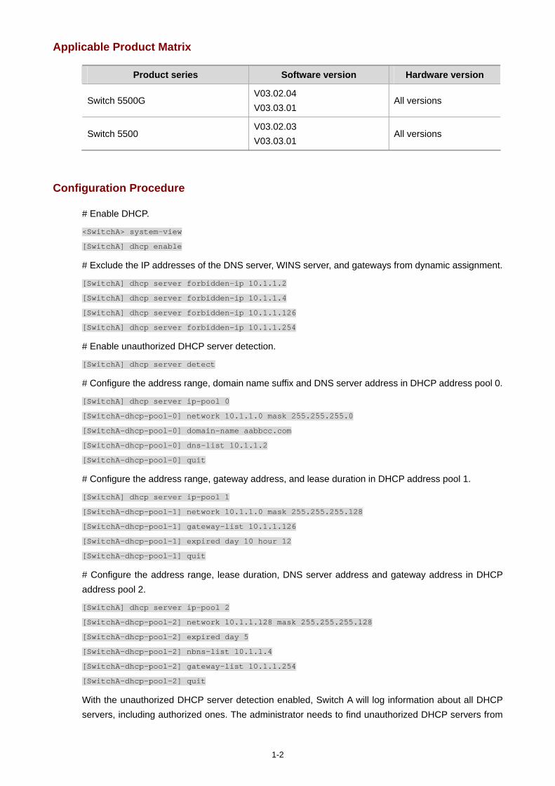
1-2
Applicable Product Matrix
Product series Software version Hardware version
Switch 5500G V03.02.04 V03.03.01
All versions
Switch 5500 V03.02.03 V03.03.01
All versions
Configuration Procedure
# Enable DHCP.
<SwitchA> system-view
[SwitchA] dhcp enable
# Exclude the IP addresses of the DNS server, WINS server, and gateways from dynamic assignment.
[SwitchA] dhcp server forbidden-ip 10.1.1.2
[SwitchA] dhcp server forbidden-ip 10.1.1.4
[SwitchA] dhcp server forbidden-ip 10.1.1.126
[SwitchA] dhcp server forbidden-ip 10.1.1.254
# Enable unauthorized DHCP server detection.
[SwitchA] dhcp server detect
# Configure the address range, domain name suffix and DNS server address in DHCP address pool 0.
[SwitchA] dhcp server ip-pool 0
[SwitchA-dhcp-pool-0] network 10.1.1.0 mask 255.255.255.0
[SwitchA-dhcp-pool-0] domain-name aabbcc.com
[SwitchA-dhcp-pool-0] dns-list 10.1.1.2
[SwitchA-dhcp-pool-0] quit
# Configure the address range, gateway address, and lease duration in DHCP address pool 1.
[SwitchA] dhcp server ip-pool 1
[SwitchA-dhcp-pool-1] network 10.1.1.0 mask 255.255.255.128
[SwitchA-dhcp-pool-1] gateway-list 10.1.1.126
[SwitchA-dhcp-pool-1] expired day 10 hour 12
[SwitchA-dhcp-pool-1] quit
# Configure the address range, lease duration, DNS server address and gateway address in DHCP address pool 2.
[SwitchA] dhcp server ip-pool 2
[SwitchA-dhcp-pool-2] network 10.1.1.128 mask 255.255.255.128
[SwitchA-dhcp-pool-2] expired day 5
[SwitchA-dhcp-pool-2] nbns-list 10.1.1.4
[SwitchA-dhcp-pool-2] gateway-list 10.1.1.254
[SwitchA-dhcp-pool-2] quit
With the unauthorized DHCP server detection enabled, Switch A will log information about all DHCP servers, including authorized ones. The administrator needs to find unauthorized DHCP servers from
1-3
the system log information. If Switch A detects an unauthorized DHCP server, the following log information is recorded.
<SwitchA>
%Apr 10 21:34:55:782 2000 SwitchA DHCPS/4/DHCPS_LOCAL_SERVER:- 1 -
Local DHCP server information(detect by server):SERVER IP = 10.1.1.5; Sourceclient
information: interface = Vlan-interface2, type = DHCP_REQUEST, CHardAddr= 00e0-fc55-0011
Complete Configuration
#
dhcp server ip-pool 0
network 10.1.1.0 mask 255.255.255.0
dns-list 10.1.1.2
domain-name aabbcc.com
#
dhcp server ip-pool 1
network 10.1.1.0 mask 255.255.255.128
gateway-list 10.1.1.126
expired day 10 hour 12
#
dhcp server ip-pool 2
network 10.1.1.128 mask 255.255.255.128
gateway-list 10.1.1.254
nbns-list 10.1.1.4
expired day 5
#
dhcp server forbidden-ip 10.1.1.2
dhcp server forbidden-ip 10.1.1.4
dhcp server forbidden-ip 10.1.1.126
dhcp server forbidden-ip 10.1.1.254
dhcp server detect
#
Precautions
If you use the inheritance relation between the parent and child address pools in this configuration, make sure that the number of IP addresses to be assigned from a child address pool does not exceed the number of its total available addresses; otherwise, extra IP addresses will be obtained from the parent address pool, and the attributes (for example, gateway) of the parent address pool are also obtained by the clients.
In this example, the number of clients requesting IP addresses from VLAN-interface 1 is recommended to be less than or equal to 122 and the number of clients requesting IP addresses from VLAN-interface 2 is recommended to be less than or equal to 124.
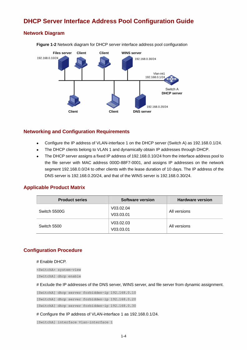
1-4
DHCP Server Interface Address Pool Configuration Guide
Network Diagram
Figure 1-2 Network diagram for DHCP server interface address pool configuration
WINS server
Client DNS server
Switch ADHCP server
Vlan-int1192.168.0.1/24
Client Client
Client
192.168.0.30/24
192.168.0.20/24
Files server192.168.0.10/24
Networking and Configuration Requirements
Configure the IP address of VLAN-interface 1 on the DHCP server (Switch A) as 192.168.0.1/24. The DHCP clients belong to VLAN 1 and dynamically obtain IP addresses through DHCP. The DHCP server assigns a fixed IP address of 192.168.0.10/24 from the interface address pool to
the file server with MAC address 000D-88F7-0001, and assigns IP addresses on the network segment 192.168.0.0/24 to other clients with the lease duration of 10 days. The IP address of the DNS server is 192.168.0.20/24, and that of the WINS server is 192.168.0.30/24.
Applicable Product Matrix
Product series Software version Hardware version
Switch 5500G V03.02.04 V03.03.01
All versions
Switch 5500 V03.02.03 V03.03.01
All versions
Configuration Procedure
# Enable DHCP.
<SwitchA> system-view
[SwitchA] dhcp enable
# Exclude the IP addresses of the DNS server, WINS server, and file server from dynamic assignment.
[SwitchA] dhcp server forbidden-ip 192.168.0.10
[SwitchA] dhcp server forbidden-ip 192.168.0.20
[SwitchA] dhcp server forbidden-ip 192.168.0.30
# Configure the IP address of VLAN-interface 1 as 192.168.0.1/24.
[SwitchA] interface Vlan-interface 1
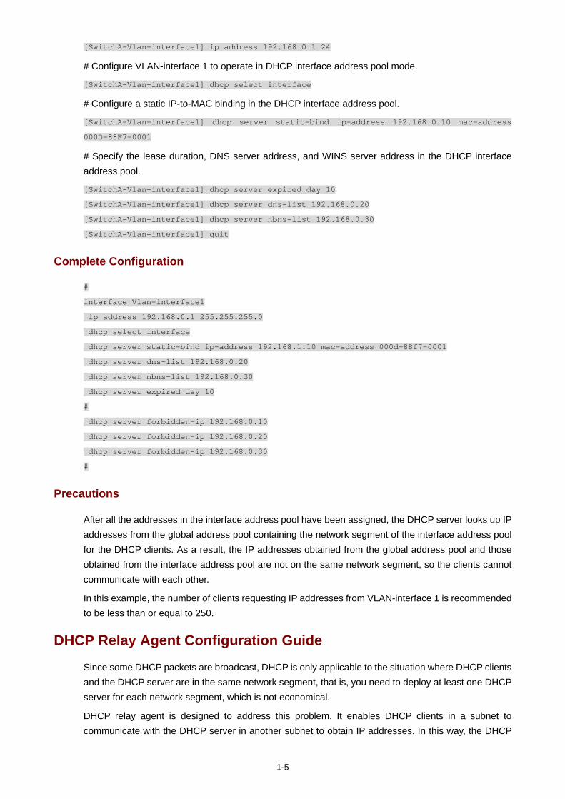
1-5
[SwitchA-Vlan-interface1] ip address 192.168.0.1 24
# Configure VLAN-interface 1 to operate in DHCP interface address pool mode.
[SwitchA-Vlan-interface1] dhcp select interface
# Configure a static IP-to-MAC binding in the DHCP interface address pool.
[SwitchA-Vlan-interface1] dhcp server static-bind ip-address 192.168.0.10 mac-address
000D-88F7-0001
# Specify the lease duration, DNS server address, and WINS server address in the DHCP interface address pool.
[SwitchA-Vlan-interface1] dhcp server expired day 10
[SwitchA-Vlan-interface1] dhcp server dns-list 192.168.0.20
[SwitchA-Vlan-interface1] dhcp server nbns-list 192.168.0.30
[SwitchA-Vlan-interface1] quit
Complete Configuration
#
interface Vlan-interface1
ip address 192.168.0.1 255.255.255.0
dhcp select interface
dhcp server static-bind ip-address 192.168.1.10 mac-address 000d-88f7-0001
dhcp server dns-list 192.168.0.20
dhcp server nbns-list 192.168.0.30
dhcp server expired day 10
#
dhcp server forbidden-ip 192.168.0.10
dhcp server forbidden-ip 192.168.0.20
dhcp server forbidden-ip 192.168.0.30
#
Precautions
After all the addresses in the interface address pool have been assigned, the DHCP server looks up IP addresses from the global address pool containing the network segment of the interface address pool for the DHCP clients. As a result, the IP addresses obtained from the global address pool and those obtained from the interface address pool are not on the same network segment, so the clients cannot communicate with each other.
In this example, the number of clients requesting IP addresses from VLAN-interface 1 is recommended to be less than or equal to 250.
DHCP Relay Agent Configuration Guide
Since some DHCP packets are broadcast, DHCP is only applicable to the situation where DHCP clients and the DHCP server are in the same network segment, that is, you need to deploy at least one DHCP server for each network segment, which is not economical.
DHCP relay agent is designed to address this problem. It enables DHCP clients in a subnet to communicate with the DHCP server in another subnet to obtain IP addresses. In this way, the DHCP
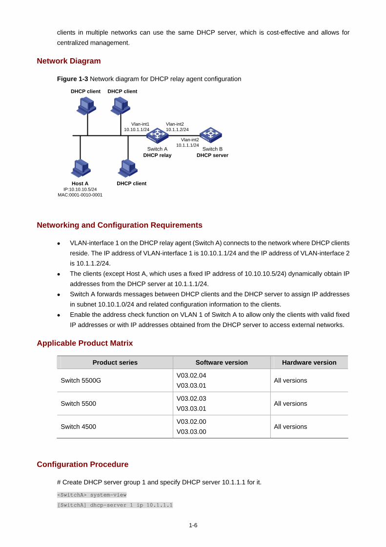
1-6
clients in multiple networks can use the same DHCP server, which is cost-effective and allows for centralized management.
Network Diagram
Figure 1-3 Network diagram for DHCP relay agent configuration
Switch BDHCP server
Switch ADHCP relay
Host AIP:10.10.10.5/24
MAC:0001-0010-0001
DHCP client
DHCP clientDHCP client
Vlan-int210.1.1.2/24
Vlan-int110.10.1.1/24
Vlan-int210.1.1.1/24
Networking and Configuration Requirements
VLAN-interface 1 on the DHCP relay agent (Switch A) connects to the network where DHCP clients reside. The IP address of VLAN-interface 1 is 10.10.1.1/24 and the IP address of VLAN-interface 2 is 10.1.1.2/24.
The clients (except Host A, which uses a fixed IP address of 10.10.10.5/24) dynamically obtain IP addresses from the DHCP server at 10.1.1.1/24.
Switch A forwards messages between DHCP clients and the DHCP server to assign IP addresses in subnet 10.10.1.0/24 and related configuration information to the clients.
Enable the address check function on VLAN 1 of Switch A to allow only the clients with valid fixed IP addresses or with IP addresses obtained from the DHCP server to access external networks.
Applicable Product Matrix
Product series Software version Hardware version
Switch 5500G V03.02.04 V03.03.01
All versions
Switch 5500 V03.02.03 V03.03.01
All versions
Switch 4500 V03.02.00 V03.03.00
All versions
Configuration Procedure
# Create DHCP server group 1 and specify DHCP server 10.1.1.1 for it.
<SwitchA> system-view
[SwitchA] dhcp-server 1 ip 10.1.1.1
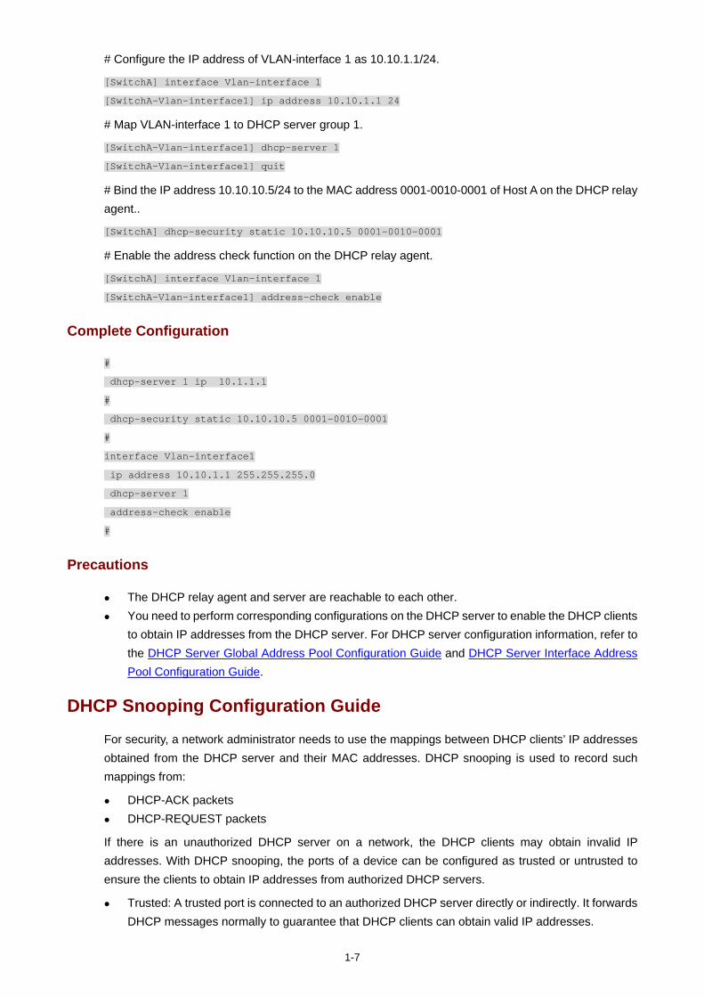
1-7
# Configure the IP address of VLAN-interface 1 as 10.10.1.1/24.
[SwitchA] interface Vlan-interface 1
[SwitchA-Vlan-interface1] ip address 10.10.1.1 24
# Map VLAN-interface 1 to DHCP server group 1.
[SwitchA-Vlan-interface1] dhcp-server 1
[SwitchA-Vlan-interface1] quit
# Bind the IP address 10.10.10.5/24 to the MAC address 0001-0010-0001 of Host A on the DHCP relay agent..
[SwitchA] dhcp-security static 10.10.10.5 0001-0010-0001
# Enable the address check function on the DHCP relay agent.
[SwitchA] interface Vlan-interface 1
[SwitchA-Vlan-interface1] address-check enable
Complete Configuration
#
dhcp-server 1 ip 10.1.1.1
#
dhcp-security static 10.10.10.5 0001-0010-0001
#
interface Vlan-interface1
ip address 10.10.1.1 255.255.255.0
dhcp-server 1
address-check enable
#
Precautions
The DHCP relay agent and server are reachable to each other. You need to perform corresponding configurations on the DHCP server to enable the DHCP clients
to obtain IP addresses from the DHCP server. For DHCP server configuration information, refer to the DHCP Server Global Address Pool Configuration Guide and DHCP Server Interface Address Pool Configuration Guide.
DHCP Snooping Configuration Guide
For security, a network administrator needs to use the mappings between DHCP clients’ IP addresses obtained from the DHCP server and their MAC addresses. DHCP snooping is used to record such mappings from:
DHCP-ACK packets DHCP-REQUEST packets
If there is an unauthorized DHCP server on a network, the DHCP clients may obtain invalid IP addresses. With DHCP snooping, the ports of a device can be configured as trusted or untrusted to ensure the clients to obtain IP addresses from authorized DHCP servers.
Trusted: A trusted port is connected to an authorized DHCP server directly or indirectly. It forwards DHCP messages normally to guarantee that DHCP clients can obtain valid IP addresses.
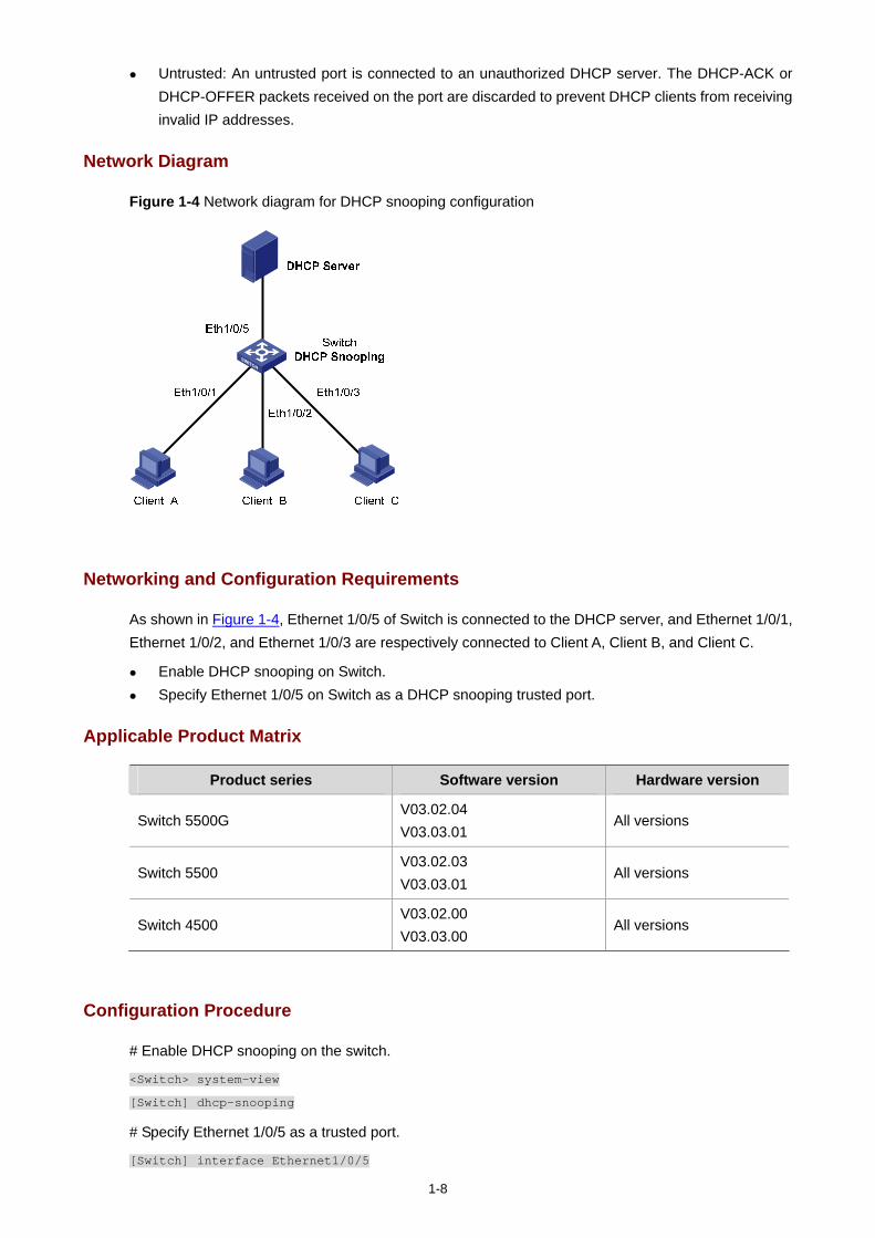
1-8
Untrusted: An untrusted port is connected to an unauthorized DHCP server. The DHCP-ACK or DHCP-OFFER packets received on the port are discarded to prevent DHCP clients from receiving invalid IP addresses.
Network Diagram
Figure 1-4 Network diagram for DHCP snooping configuration
Networking and Configuration Requirements
As shown in Figure 1-4, Ethernet 1/0/5 of Switch is connected to the DHCP server, and Ethernet 1/0/1, Ethernet 1/0/2, and Ethernet 1/0/3 are respectively connected to Client A, Client B, and Client C.
Enable DHCP snooping on Switch. Specify Ethernet 1/0/5 on Switch as a DHCP snooping trusted port.
Applicable Product Matrix
Product series Software version Hardware version
Switch 5500G V03.02.04 V03.03.01
All versions
Switch 5500 V03.02.03 V03.03.01
All versions
Switch 4500 V03.02.00 V03.03.00
All versions
Configuration Procedure
# Enable DHCP snooping on the switch.
<Switch> system-view
[Switch] dhcp-snooping
# Specify Ethernet 1/0/5 as a trusted port.
[Switch] interface Ethernet1/0/5
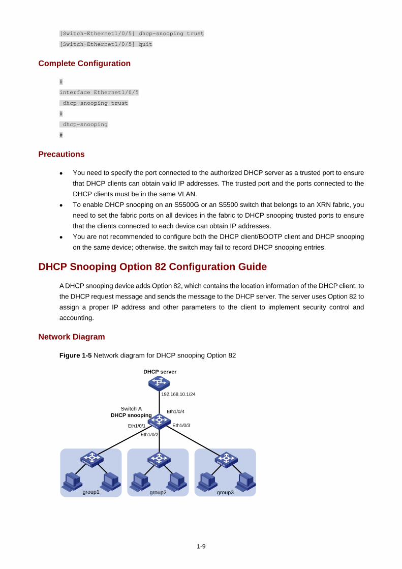
1-9
[Switch-Ethernet1/0/5] dhcp-snooping trust
[Switch-Ethernet1/0/5] quit
Complete Configuration
#
interface Ethernet1/0/5
dhcp-snooping trust
#
dhcp-snooping
#
Precautions
You need to specify the port connected to the authorized DHCP server as a trusted port to ensure that DHCP clients can obtain valid IP addresses. The trusted port and the ports connected to the DHCP clients must be in the same VLAN.
To enable DHCP snooping on an S5500G or an S5500 switch that belongs to an XRN fabric, you need to set the fabric ports on all devices in the fabric to DHCP snooping trusted ports to ensure that the clients connected to each device can obtain IP addresses.
You are not recommended to configure both the DHCP client/BOOTP client and DHCP snooping on the same device; otherwise, the switch may fail to record DHCP snooping entries.
DHCP Snooping Option 82 Configuration Guide
A DHCP snooping device adds Option 82, which contains the location information of the DHCP client, to the DHCP request message and sends the message to the DHCP server. The server uses Option 82 to assign a proper IP address and other parameters to the client to implement security control and accounting.
Network Diagram
Figure 1-5 Network diagram for DHCP snooping Option 82
DHCP server
Switch ADHCP snooping
group3group1 group2
Eth1/0/1
Eth1/0/2
Eth1/0/3
Eth1/0/4
192.168.10.1/24
1-10
Networking and Configuration Requirements
The work area of an enterprise is divided into three groups, group 1, group 2, and group 3, which are located in three rooms. A DHCP server is deployed to assign IP addresses of different segments to the three groups.
It is required that:
The DHCP server assigns IP addresses on network segment 192.168.10.0/24 to devices in the work area. The lease time is 12 hours, and the IP addresses of the DNS server and the WINS server are 192.168.100.2 and 192.168.100.3 respectively.
Enable DHCP snooping on Switch A and specify Ethernet 1/0/4 as a DHCP snooping trusted port. Group 1, group 2 and group 3 are connected to the DHCP snooping device through Ethernet 1/0/1,
Ethernet 1/0/2 and Ethernet 1/0/3 respectively to communicate with the DHCP server. Enable Option 82 support on the DHCP snooping device, and put the user group information into
Option 82 of DHCP messages. The DHCP server assigns IP addresses ranging from 192.168.10.2 to 192.168.10.25 to clients in
group 1, assigns IP addresses ranging from 192.168.10.100 to 192.168.10.150 to clients in group 2, and assigns IP addresses ranging from 192.168.10.151 to 192.168.10.200 to clients in group 3.
Applicable Product Matrix
Product series Software version Hardware version
Switch 5500G V03.03.01 All versions
Switch 5500 V03.03.01 All versions
Switch 4500 V03.03.00 All versions
Configuration Procedure
Configuring Switch A
# Enable DHCP snooping.
<SwitchA> system-view
[SwitchA] dhcp-snooping
# Configure Ethernet 1/0/4 as a DHCP snooping trusted port.
[SwitchA] interface ethernet1/0/4
[SwitchA-Ethernet1/0/4] dhcp-snooping trust
[SwitchA-Ethernet1/0/4] quit
# Enable Switch A to support Option 82.
[SwitchA] dhcp-snooping information enable
# Pad the Option 82 remote-id ID sub-option with group 1 on Ethernet 1/0/1.
[SwitchA] interface ethernet1/0/1
[SwitchA-Ethernet1/0/1] dhcp-snooping information remote-id string group1
[SwitchA-Ethernet1/0/1] quit
# Pad the Option 82 remote-id ID sub-option with group 2 on Ethernet 1/0/2.
[SwitchA] interface ethernet1/0/2
1-11
[SwitchA-Ethernet1/0/2] dhcp-snooping information remote-id string group2
[SwitchA-GigabitEthernet1/0/2] quit
# Pad the Option 82 remote-id ID sub-option with group 3 on Ethernet 1/0/3
[SwitchA] interface ethernet1/0/3
[SwitchA-Ethernet1/0/3] dhcp-snooping information remote-id string group3
[SwitchA-Ethernet1/0/3] quit
Configuration on the DHCP Server
The DHCP server is configured on a Cisco Catalyst 3745 switch with software version IOS 12.3(11)T2. To configure a device of another type or version as the DHCP server, refer to the related user manual.
# Configure the server interface IP address as 192.168.10.1/24.
Server> enable
Server# configure terminal
Server(config)# interface fastethernet 0/0
Server(config-if)# ip address 192.168.10.1 255.255.255.0
Server(config-if)# exit
# Enable DHCP server, and configure the DHCP server to assign IP addresses based on Option 82.
Server(config)# service dhcp
Server(config)# ip dhcp use class
# Create a DHCP class for clients in group 1, and specify the corresponding remote ID sub-option for matching. For the content not to be matched, enter the wildcard ”*”.
Server(config)# ip dhcp class group1
Server(dhcp-class)# relay agent information
Server(dhcp-class-relayinfo)# relay-information hex 0208000600010001*
Server(dhcp-class-relayinfo)# exit
# Create a DHCP class for clients in group 2, and specify the corresponding remote ID sub-option for matching.
Server(config)# ip dhcp class group2
Server(dhcp-class)# relay agent information
Server(dhcp-class-relayinfo)# relay-information hex 0208000600010002*
Server(dhcp-class-relayinfo)# exit
# Create a DHCP class for clients in group 3 and specify the corresponding remote ID sub-option for matching.
Server(config)# ip dhcp class group3
Server(dhcp-class)# relay agent information
Server(dhcp-class-relayinfo)# relay-information hex 0208000600010003*
Server(dhcp-class-relayinfo)# exit
# Create a DHCP address pool named office, and specify the lease time, gateway address, DNS server address, and WINS server address for clients.
1-12
Server(config)# ip dhcp pool office
Server(dhcp-config)# network 192.168.10.0
Server(dhcp-config)# lease 0 12
Server(dhcp-config)# default-router 192.168.10.1
Server(dhcp-config)# dns-server 192.168.100.2
Server(dhcp-config)# netbios-name-server 192.168.100.3
# Specify address ranges for the three DHCP classes respectively.
Server(dhcp-config)# class group1
Server(dhcp-pool-class)# address range 192.168.10.2 192.168.10.25
Server(dhcp-pool-class)# class group2
Server(dhcp-pool-class)# address range 192.168.10.100 192.168.10.150
Server(dhcp-pool-class)# class group3
Server(dhcp-pool-class)# address range 192.168.10.151 192.168.10.200
Complete Configuration
#
dhcp-snooping information enable
dhcp-snooping information strategy replace
#
interface Ethernet1/0/1
dhcp-snooping information remote-id string group1
#
interface Ethernet1/0/2
dhcp-snooping information remote-id string group2
#
interface Ethernet1/0/3
dhcp-snooping information remote-id string group3
#
interface Ethernet1/0/4
dhcp-snooping trust
#
dhcp-snooping
#
Precautions
Option 82 is effective only when the DHCP snooping function is enabled. Enable Option 82 support on the DHCP snooping device that is closest to the DHCP clients to
locate the clients accurately (recommended).
DHCP Accounting Configuration Guide
DHCP accounting allows a DHCP server to notify the RADIUS server of the start/end of accounting when it assigns/releases a lease. The cooperation of the DHCP server and RADIUS server implements the network accounting function and ensures network security at the same time.
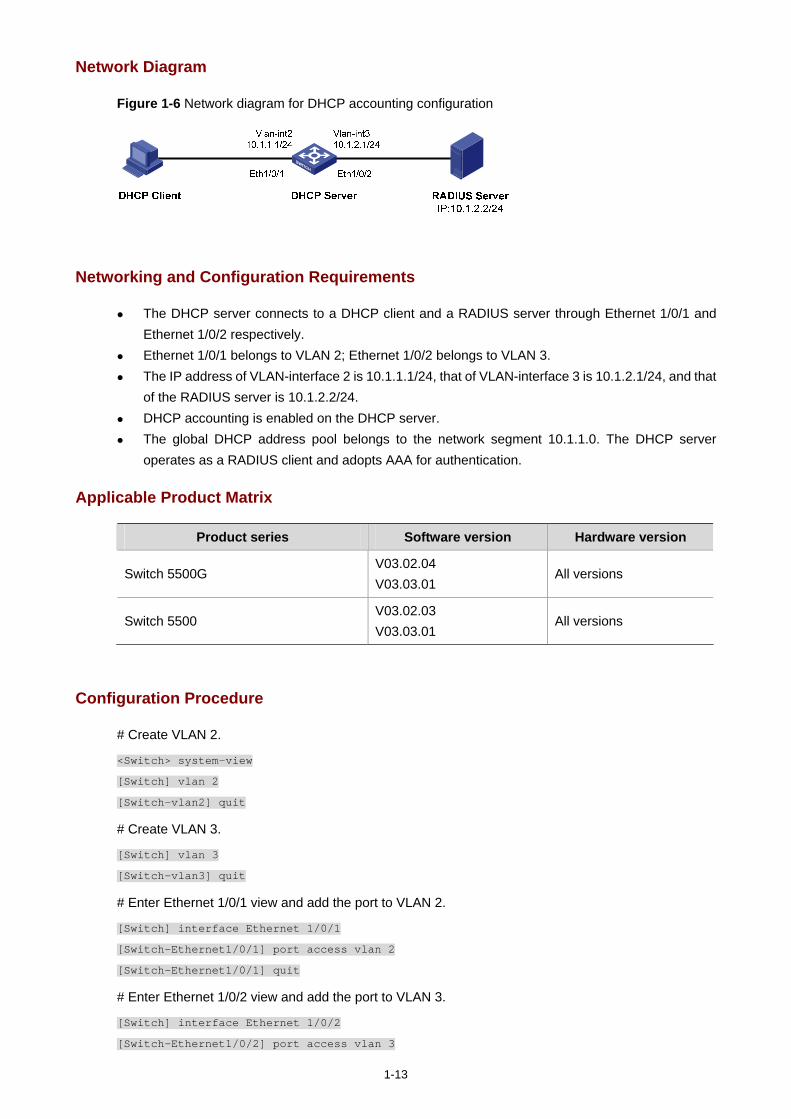
1-13
Network Diagram
Figure 1-6 Network diagram for DHCP accounting configuration
Networking and Configuration Requirements
The DHCP server connects to a DHCP client and a RADIUS server through Ethernet 1/0/1 and Ethernet 1/0/2 respectively.
Ethernet 1/0/1 belongs to VLAN 2; Ethernet 1/0/2 belongs to VLAN 3. The IP address of VLAN-interface 2 is 10.1.1.1/24, that of VLAN-interface 3 is 10.1.2.1/24, and that
of the RADIUS server is 10.1.2.2/24. DHCP accounting is enabled on the DHCP server. The global DHCP address pool belongs to the network segment 10.1.1.0. The DHCP server
operates as a RADIUS client and adopts AAA for authentication.
Applicable Product Matrix
Product series Software version Hardware version
Switch 5500G V03.02.04 V03.03.01
All versions
Switch 5500 V03.02.03 V03.03.01
All versions
Configuration Procedure
# Create VLAN 2.
<Switch> system-view
[Switch] vlan 2
[Switch-vlan2] quit
# Create VLAN 3.
[Switch] vlan 3
[Switch-vlan3] quit
# Enter Ethernet 1/0/1 view and add the port to VLAN 2.
[Switch] interface Ethernet 1/0/1
[Switch-Ethernet1/0/1] port access vlan 2
[Switch-Ethernet1/0/1] quit
# Enter Ethernet 1/0/2 view and add the port to VLAN 3.
[Switch] interface Ethernet 1/0/2
[Switch-Ethernet1/0/2] port access vlan 3
1-14
[Switch-Ethernet1/0/2] quit
# Enter VLAN-interface 2 view and assign the IP address 10.1.1.1/24 to the VLAN interface.
[Switch] interface Vlan-interface 2
[Switch-Vlan-interface2] ip address 10.1.1.1 24
[Switch-Vlan-interface2] quit
# Enter VLAN-interface 3 view and assign the IP address 10.1.2.1/24 to the VLAN interface.
[Switch] interface Vlan-interface 3
[Switch-Vlan-interface3] ip address 10.1.2.1 24
[Switch-Vlan-interface3] quit
# Create a RADIUS scheme and a domain, and then associate the domain with the RADIUS scheme.
[Switch] radius scheme 123
[Switch-radius-123] primary authentication 10.1.2.2
[Switch-radius-123] primary accounting 10.1.2.2
[Switch-radius-123] quit
[Switch] domain 123
[Switch-isp-123] scheme radius-scheme 123
[Switch-isp-123] quit
# Create an address pool on the DHCP server.
[Switch] dhcp server ip-pool test
[Switch-dhcp-pool-test] network 10.1.1.0 mask 255.255.255.0
# Enable DHCP accounting.
[Switch-dhcp-pool-test] accounting domain 123
Complete Configuration
#
radius scheme 123
primary authentication 10.1.2.2
primary accounting 10.1.2.2
#
domain 123
scheme radius-scheme 123
#
dhcp server ip-pool test
network 10.1.1.0 mask 255.255.255.0
accounting domain 123
#
vlan 2
#
vlan 3
#
interface Vlan-interface2
ip address 10.1.1.1 255.255.255.0
#
interface Vlan-interface3
1-15
ip address 10.1.2.1 255.255.255.0
#
interface Ethernet1/0/1
port access vlan 2
#
interface Ethernet1/0/2
port access vlan 3
#
Precautions
Before configuring DHCP accounting, make sure that:
The DHCP server is configured (such as the address pool, lease time and other configuration parameters).
The DHCP client is enabled. Routes are reachable.
DHCP Client Configuration Guide
With the DHCP client enabled on an interface, the interface will use DHCP to obtain configuration parameters such as an IP address from the DHCP server.
Network Diagram
Refer to Figure 1-1.
Networking and Configuration Requirements
Configure VLAN-interface 1 on Switch B to obtain an IP address through DHCP.
Applicable Product Matrix
Product series Software version Hardware version
Switch 5500G V03.02.04 V03.03.01
All versions
Switch 5500 V03.02.03 V03.03.01
All versions
Switch 4500 V03.02.00 V03.03.00
All versions
Switch 4200G V03.02.00 All versions
Switch 4210 V03.01.00 V03.01.05
All versions
Configuration Procedure
# Create VLAN-interface 1 on Switch B and enter its view.
<SwitchB> system-view

1-16
[SwitchB] interface Vlan-interface 1
# Configure VLAN-interface 1 to obtain an IP address through DHCP.
[SwitchB-Vlan-interface1] ip address dhcp-alloc
[SwitchB-Vlan-interface1] quit
Complete Configuration
#
interface Vlan-interface1
ip address dhcp-alloc
#
Precautions
None
i
Table of Contents
1 ACL Configuration Guide ·························································································································1-1 Configuring Basic ACLs ··························································································································1-1
Network Diagram·····························································································································1-1 Networking and Configuration Requirements··················································································1-1 Applicable Product Matrix················································································································1-1 Configuration Procedure··················································································································1-1 Complete Configuration···················································································································1-2 Precautions······································································································································1-2
Configuring Advanced ACLs···················································································································1-2 Network Diagram·····························································································································1-3 Networking and Configuration Requirements··················································································1-3 Applicable Product Matrix················································································································1-3 Configuration Procedure··················································································································1-3 Complete Configuration···················································································································1-4 Precautions······································································································································1-4
Configuring Ethernet Frame Header ACLs·····························································································1-4 Network Diagram·····························································································································1-4 Networking and Configuration Requirements··················································································1-4 Applicable Product Matrix················································································································1-5 Configuration Procedure··················································································································1-5 Complete Configuration···················································································································1-5 Precautions······································································································································1-6
Configuring User-Defined ACLs··············································································································1-6 Network Diagram·····························································································································1-6 Networking and Configuration Requirements··················································································1-6 Applicable Product Matrix················································································································1-6 Configuration Procedure··················································································································1-7 Complete Configuration···················································································································1-7 Precautions······································································································································1-7
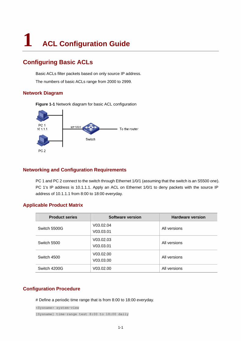
1-1
1 ACL Configuration Guide
Configuring Basic ACLs
Basic ACLs filter packets based on only source IP address.
The numbers of basic ACLs range from 2000 to 2999.
Network Diagram
Figure 1-1 Network diagram for basic ACL configuration
Networking and Configuration Requirements
PC 1 and PC 2 connect to the switch through Ethernet 1/0/1 (assuming that the switch is an S5500 one). PC 1’s IP address is 10.1.1.1. Apply an ACL on Ethernet 1/0/1 to deny packets with the source IP address of 10.1.1.1 from 8:00 to 18:00 everyday.
Applicable Product Matrix
Product series Software version Hardware version
Switch 5500G V03.02.04 V03.03.01
All versions
Switch 5500 V03.02.03 V03.03.01
All versions
Switch 4500 V03.02.00 V03.03.00
All versions
Switch 4200G V03.02.00 All versions
Configuration Procedure
# Define a periodic time range that is from 8:00 to 18:00 everyday.
<Sysname> system-view
[Sysname] time-range test 8:00 to 18:00 daily
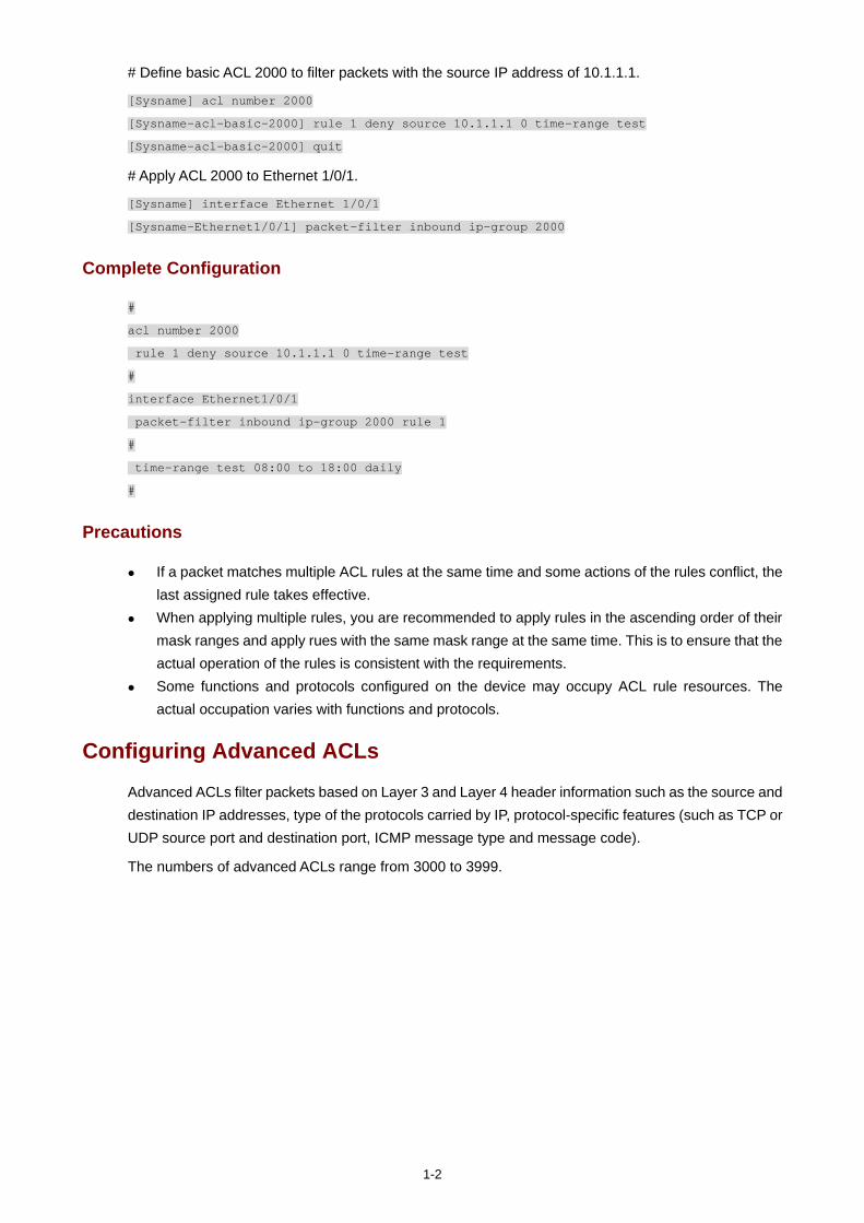
1-2
# Define basic ACL 2000 to filter packets with the source IP address of 10.1.1.1.
[Sysname] acl number 2000
[Sysname-acl-basic-2000] rule 1 deny source 10.1.1.1 0 time-range test
[Sysname-acl-basic-2000] quit
# Apply ACL 2000 to Ethernet 1/0/1.
[Sysname] interface Ethernet 1/0/1
[Sysname-Ethernet1/0/1] packet-filter inbound ip-group 2000
Complete Configuration
#
acl number 2000
rule 1 deny source 10.1.1.1 0 time-range test
#
interface Ethernet1/0/1
packet-filter inbound ip-group 2000 rule 1
#
time-range test 08:00 to 18:00 daily
#
Precautions
If a packet matches multiple ACL rules at the same time and some actions of the rules conflict, the last assigned rule takes effective.
When applying multiple rules, you are recommended to apply rules in the ascending order of their mask ranges and apply rues with the same mask range at the same time. This is to ensure that the actual operation of the rules is consistent with the requirements.
Some functions and protocols configured on the device may occupy ACL rule resources. The actual occupation varies with functions and protocols.
Configuring Advanced ACLs
Advanced ACLs filter packets based on Layer 3 and Layer 4 header information such as the source and destination IP addresses, type of the protocols carried by IP, protocol-specific features (such as TCP or UDP source port and destination port, ICMP message type and message code).
The numbers of advanced ACLs range from 3000 to 3999.
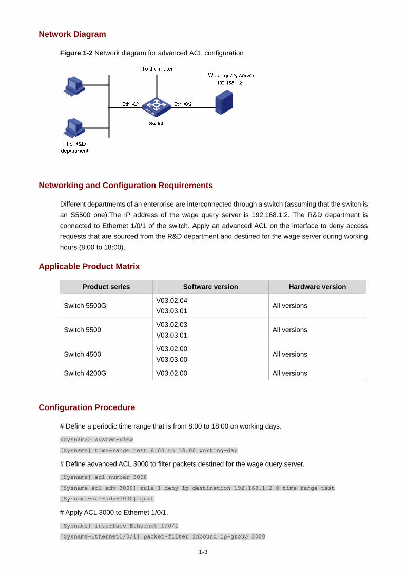
1-3
Network Diagram
Figure 1-2 Network diagram for advanced ACL configuration
Networking and Configuration Requirements
Different departments of an enterprise are interconnected through a switch (assuming that the switch is an S5500 one).The IP address of the wage query server is 192.168.1.2. The R&D department is connected to Ethernet 1/0/1 of the switch. Apply an advanced ACL on the interface to deny access requests that are sourced from the R&D department and destined for the wage server during working hours (8:00 to 18:00).
Applicable Product Matrix
Product series Software version Hardware version
Switch 5500G V03.02.04 V03.03.01
All versions
Switch 5500 V03.02.03 V03.03.01
All versions
Switch 4500 V03.02.00 V03.03.00
All versions
Switch 4200G V03.02.00 All versions
Configuration Procedure
# Define a periodic time range that is from 8:00 to 18:00 on working days.
<Sysname> system-view
[Sysname] time-range test 8:00 to 18:00 working-day
# Define advanced ACL 3000 to filter packets destined for the wage query server.
[Sysname] acl number 3000
[Sysname-acl-adv-3000] rule 1 deny ip destination 192.168.1.2 0 time-range test
[Sysname-acl-adv-3000] quit
# Apply ACL 3000 to Ethernet 1/0/1.
[Sysname] interface Ethernet 1/0/1
[Sysname-Ethernet1/0/1] packet-filter inbound ip-group 3000

1-4
Complete Configuration
#
acl number 3000
rule 1 deny IP destination 192.168.1.2 0 time-range test
#
interface Ethernet1/0/1
packet-filter inbound ip-group 3000 rule 1
#
time-range test 08:00 to 18:00 working-day
#
Precautions
ACL 3998 and ACL 3999 are reserved for cluster management. If a packet matches multiple ACL rules at the same time and some actions of the rules conflict, the
last assigned rule takes effective. For an advanced ACL applied to a port, if a rule defines the TCP/UDP port information, the operator
argument can only be eq. When applying multiple rules, you are recommended to apply rules in the ascending order of their
mask ranges and apply rues with the same mask range at the same time. This is to ensure that the actual operation of the rules is consistent with the requirements.
Some functions and protocols configured on the device may occupy ACL rule resources. The actual occupation varies with functions and protocols.
Configuring Ethernet Frame Header ACLs
Ethernet frame header ACLs filter packets based on Layer 2 header information such as source and destination MAC addresses, 802.1p priority and type of the Layer 2 protocol.
The numbers of Ethernet frame header ACLs range from 4000 to 4999.
Network Diagram
Figure 1-3 Network diagram for Ethernet frame header ACL configuration
Networking and Configuration Requirements
PC 1 and PC 2 connect to the switch through Ethernet 1/0/1 (assuming that the switch is an S5500 one). PC 1’s MAC address is 0011-0011-0011. Apply an Ethernet frame header ACL on the interface to filter
1-5
packets with the source MAC address of 0011-0011-0011 and the destination MAC address of 0011-0011-0012 from 8:00 to 18:00 everyday.
Applicable Product Matrix
Product series Software version Hardware version
Switch 5500G V03.02.04 V03.03.01
All versions
Switch 5500 V03.02.03 V03.03.01
All versions
Switch 4500 V03.02.00 V03.03.00
All versions
Switch 4200G V03.02.00 All versions
Configuration Procedure
# Define a periodic time range that is from 8:00 to 18:00 everyday.
<Sysname> system-view
[Sysname] time-range test 8:00 to 18:00 daily
# Define ACL 4000 to filter packets with the source MAC address of 0011-0011-0011 and the destination MAC address of 0011-0011-0012.
[Sysname] acl number 4000
[Sysname-acl-ethernetframe-4000] rule 1 deny source 0011-0011-0011 ffff-ffff-ffff dest
0011-0011-0012 ffff-ffff-ffff time-range test
[Sysname-acl-ethernetframe-4000] quit
# Apply ACL 4000 to Ethernet 1/0/1.
[Sysname] interface Ethernet 1/0/1
[Sysname-Ethernet1/0/1] packet-filter inbound link-group 4000
Complete Configuration
#
acl number 4000
rule 1 deny source 0011-0011-0011 ffff-ffff-ffff dest 0011-0011-0012 ffff-ffff-ffff
time-range test
#
interface Ethernet1/0/1
packet-filter inbound link-group 4000 rule 1
#
time-range test 08:00 to 18:00 daily
#
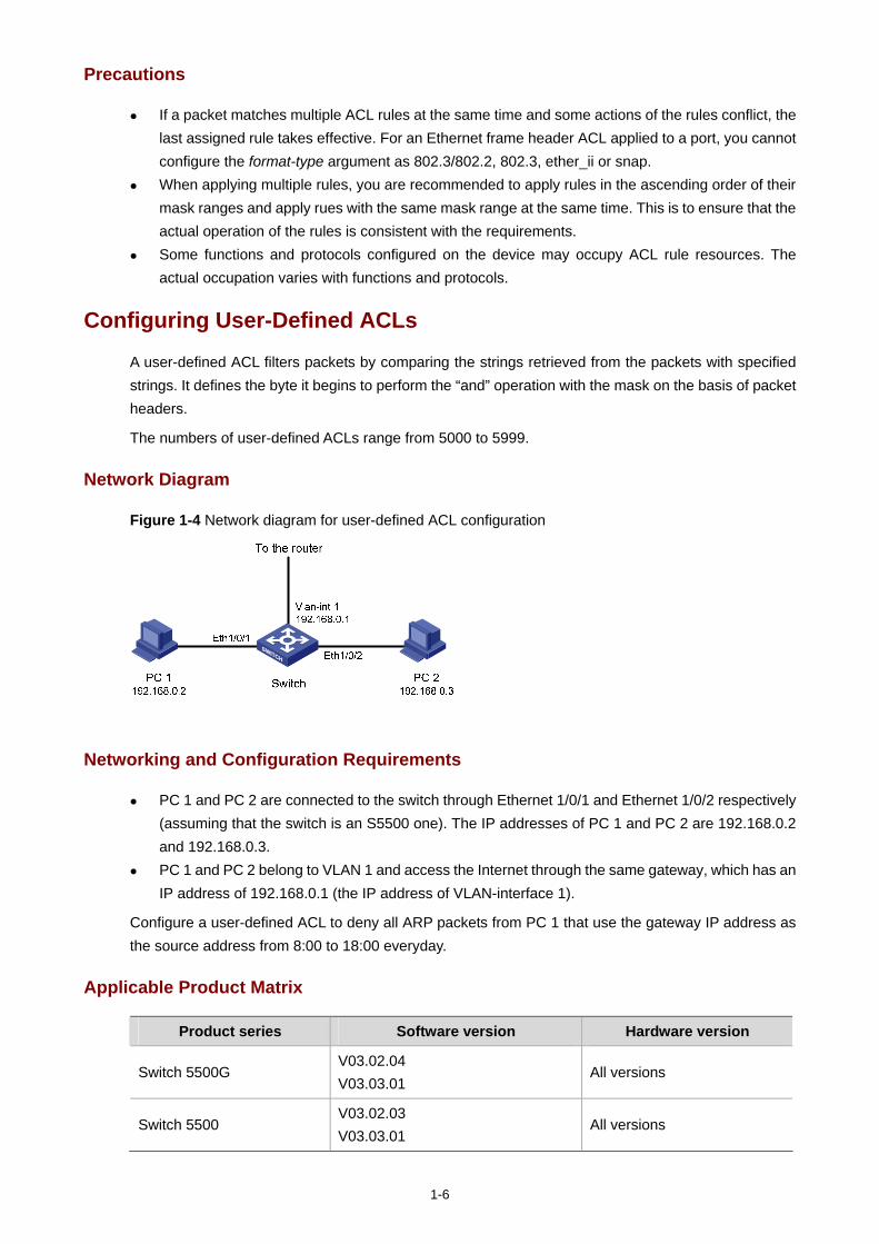
1-6
Precautions
If a packet matches multiple ACL rules at the same time and some actions of the rules conflict, the last assigned rule takes effective. For an Ethernet frame header ACL applied to a port, you cannot configure the format-type argument as 802.3/802.2, 802.3, ether_ii or snap.
When applying multiple rules, you are recommended to apply rules in the ascending order of their mask ranges and apply rues with the same mask range at the same time. This is to ensure that the actual operation of the rules is consistent with the requirements.
Some functions and protocols configured on the device may occupy ACL rule resources. The actual occupation varies with functions and protocols.
Configuring User-Defined ACLs
A user-defined ACL filters packets by comparing the strings retrieved from the packets with specified strings. It defines the byte it begins to perform the “and” operation with the mask on the basis of packet headers.
The numbers of user-defined ACLs range from 5000 to 5999.
Network Diagram
Figure 1-4 Network diagram for user-defined ACL configuration
Networking and Configuration Requirements
PC 1 and PC 2 are connected to the switch through Ethernet 1/0/1 and Ethernet 1/0/2 respectively (assuming that the switch is an S5500 one). The IP addresses of PC 1 and PC 2 are 192.168.0.2 and 192.168.0.3.
PC 1 and PC 2 belong to VLAN 1 and access the Internet through the same gateway, which has an IP address of 192.168.0.1 (the IP address of VLAN-interface 1).
Configure a user-defined ACL to deny all ARP packets from PC 1 that use the gateway IP address as the source address from 8:00 to 18:00 everyday.
Applicable Product Matrix
Product series Software version Hardware version
Switch 5500G V03.02.04 V03.03.01
All versions
Switch 5500 V03.02.03 V03.03.01
All versions
1-7
Product series Software version Hardware version
Switch 4500 V03.02.00 V03.03.00
All versions
Configuration Procedure
# Define a periodic time range that is from 8:00 to 18:00 everyday.
<Sysname> system-view
[Sysname] time-range test 8:00 to 18:00 daily
# Define ACL 5000 to deny any ARP packet whose source IP address is 192.168.0.1 from 8:00 to 18:00 everyday (provided that VLAN-VPN is not enabled on any port).In the ACL rule, 0806 is the ARP protocol number, 16 is the protocol type field offset of the internally processed Ethernet frame, c0a80001 is the hexadecimal form of 192.168.0.1, and 32 is the source IP address field offset of the internally processed ARP packet.
[Sysname] acl number 5000
[Sysname-acl-user-5000] rule 1 deny 0806 ffff 16 c0a80001 ffffffff 32 time-range test
# Apply ACL 5000 to Ethernet 1/0/1.
[Sysname] interface Ethernet 1/0/1
[Sysname-Ethernet1/0/1] packet-filter inbound user-group 5000
Complete Configuration
#
acl number 5000
rule 1 deny 0806 ffff 16 c0a80001 ffffffff 32 time-range test
#
interface Ethernet1/0/1
packet-filter inbound user-group 5000 rule 1
#
time-range test 08:00 to 18:00 daily
#
Precautions
Some functions and protocols configured on the device may occupy ACL rule resources. The actual occupation varies with functions and protocols.
For an S5500 or S4500 series Ethernet switch, if VLAN-VPN is not enabled, each packet in the switch carries one VLAN tag which is 4 bytes long; If VLAN-VPN is enabled on a port, each packet in the switch carries two VLAN tags, which are 8 bytes long. Pay attention to the above information when configuring a rule that matches specific fields of packets.
For an S5500G series Ethernet switch, each packet in the switch carries two VLAN tags, which are 8 bytes long. Pay attention to the above information when configuring a rule that matches specific fields of packets.
The command for defining a user-defined ACL rule is rule [ rule-id ] { deny | permit } [ rule-string rule-mask offset ] &<1-8> [ time-range time-name ], where, rule-id refers to the ACL number,
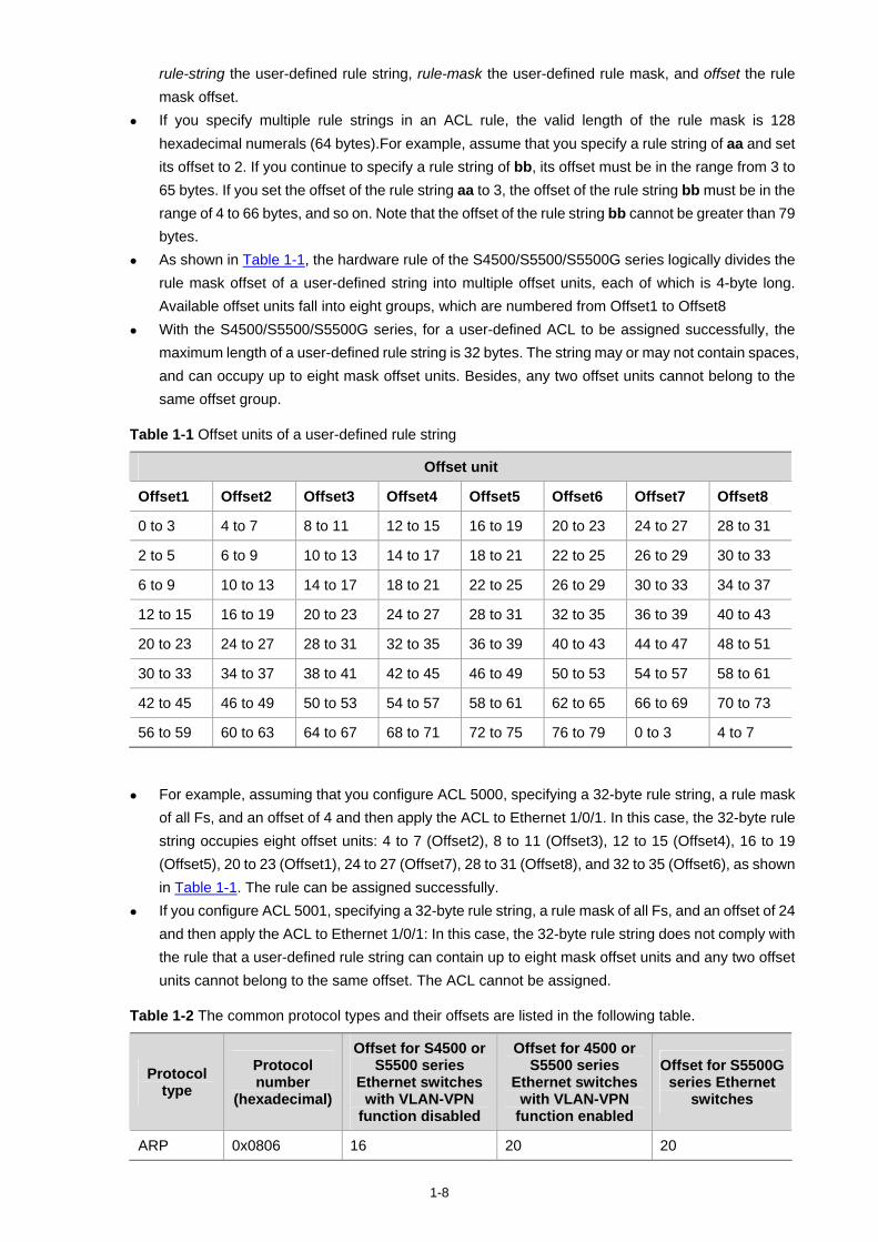
1-8
rule-string the user-defined rule string, rule-mask the user-defined rule mask, and offset the rule mask offset.
If you specify multiple rule strings in an ACL rule, the valid length of the rule mask is 128 hexadecimal numerals (64 bytes).For example, assume that you specify a rule string of aa and set its offset to 2. If you continue to specify a rule string of bb, its offset must be in the range from 3 to 65 bytes. If you set the offset of the rule string aa to 3, the offset of the rule string bb must be in the range of 4 to 66 bytes, and so on. Note that the offset of the rule string bb cannot be greater than 79 bytes.
As shown in Table 1-1, the hardware rule of the S4500/S5500/S5500G series logically divides the rule mask offset of a user-defined string into multiple offset units, each of which is 4-byte long. Available offset units fall into eight groups, which are numbered from Offset1 to Offset8
With the S4500/S5500/S5500G series, for a user-defined ACL to be assigned successfully, the maximum length of a user-defined rule string is 32 bytes. The string may or may not contain spaces, and can occupy up to eight mask offset units. Besides, any two offset units cannot belong to the same offset group.
Table 1-1 Offset units of a user-defined rule string
Offset unit
Offset1 Offset2 Offset3 Offset4 Offset5 Offset6 Offset7 Offset8
0 to 3 4 to 7 8 to 11 12 to 15 16 to 19 20 to 23 24 to 27 28 to 31
2 to 5 6 to 9 10 to 13 14 to 17 18 to 21 22 to 25 26 to 29 30 to 33
6 to 9 10 to 13 14 to 17 18 to 21 22 to 25 26 to 29 30 to 33 34 to 37
12 to 15 16 to 19 20 to 23 24 to 27 28 to 31 32 to 35 36 to 39 40 to 43
20 to 23 24 to 27 28 to 31 32 to 35 36 to 39 40 to 43 44 to 47 48 to 51
30 to 33 34 to 37 38 to 41 42 to 45 46 to 49 50 to 53 54 to 57 58 to 61
42 to 45 46 to 49 50 to 53 54 to 57 58 to 61 62 to 65 66 to 69 70 to 73
56 to 59 60 to 63 64 to 67 68 to 71 72 to 75 76 to 79 0 to 3 4 to 7
For example, assuming that you configure ACL 5000, specifying a 32-byte rule string, a rule mask of all Fs, and an offset of 4 and then apply the ACL to Ethernet 1/0/1. In this case, the 32-byte rule string occupies eight offset units: 4 to 7 (Offset2), 8 to 11 (Offset3), 12 to 15 (Offset4), 16 to 19 (Offset5), 20 to 23 (Offset1), 24 to 27 (Offset7), 28 to 31 (Offset8), and 32 to 35 (Offset6), as shown in Table 1-1. The rule can be assigned successfully.
If you configure ACL 5001, specifying a 32-byte rule string, a rule mask of all Fs, and an offset of 24 and then apply the ACL to Ethernet 1/0/1: In this case, the 32-byte rule string does not comply with the rule that a user-defined rule string can contain up to eight mask offset units and any two offset units cannot belong to the same offset. The ACL cannot be assigned.
Table 1-2 The common protocol types and their offsets are listed in the following table.
Protocol type
Protocol number
(hexadecimal)
Offset for S4500 or S5500 series
Ethernet switches with VLAN-VPN
function disabled
Offset for 4500 or S5500 series
Ethernet switches with VLAN-VPN
function enabled
Offset for S5500G series Ethernet
switches
ARP 0x0806 16 20 20
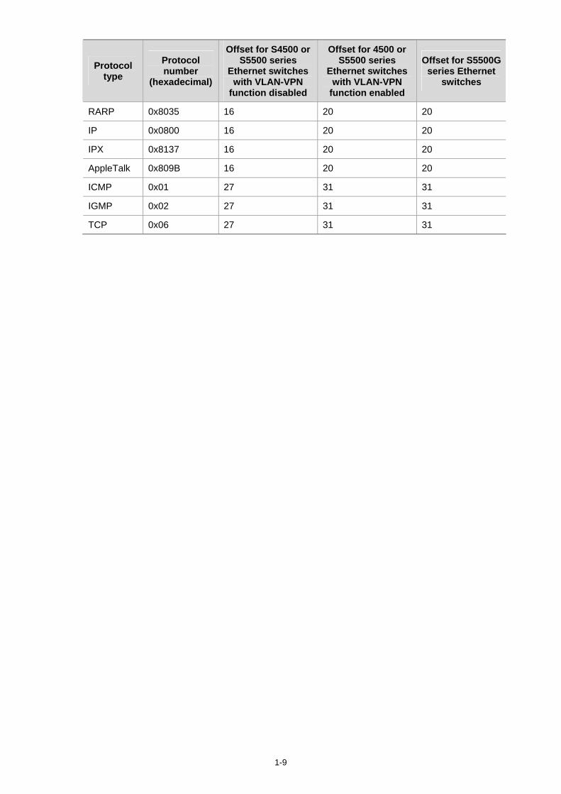
1-9
Protocol type
Protocol number
(hexadecimal)
Offset for S4500 or S5500 series
Ethernet switches with VLAN-VPN
function disabled
Offset for 4500 or S5500 series
Ethernet switches with VLAN-VPN
function enabled
Offset for S5500G series Ethernet
switches
RARP 0x8035 16 20 20
IP 0x0800 16 20 20
IPX 0x8137 16 20 20
AppleTalk 0x809B 16 20 20
ICMP 0x01 27 31 31
IGMP 0x02 27 31 31
TCP 0x06 27 31 31
i
Table of Contents
1 QoS Configuration Guide ·························································································································1-1 Configuring Traffic Policing and Line Rate······························································································1-1
Network Diagram·····························································································································1-1 Networking and Configuration Requirements··················································································1-1 Applicable Product Matrix················································································································1-1 Configuration Procedure··················································································································1-2 Complete Configuration···················································································································1-2 Precautions······································································································································1-2
Configuring Priority Marking and Queue Scheduling··············································································1-3 Network Diagram·····························································································································1-3 Networking and Configuration Requirements··················································································1-3 Applicable Product Matrix················································································································1-3 Configuration Procedure··················································································································1-4 Complete Configuration···················································································································1-5 Precautions······································································································································1-5
Configuring Traffic Redirecting and Traffic Accounting ··········································································1-9 Network Diagram·····························································································································1-9 Networking and Configuration Requirements··················································································1-9 Applicable Product Matrix················································································································1-9 Configuration Procedure··················································································································1-9 Complete Configuration·················································································································1-10 Precautions····································································································································1-11
2 QoS Profile Configuration Guide ·············································································································2-1 Configuring QoS Profile ··························································································································2-1
Network Diagram·····························································································································2-1 Networking and Configuration Requirements··················································································2-1 Applicable Product Matrix················································································································2-1 Configuration Procedure··················································································································2-1 Complete Configuration···················································································································2-2 Precautions······································································································································2-3
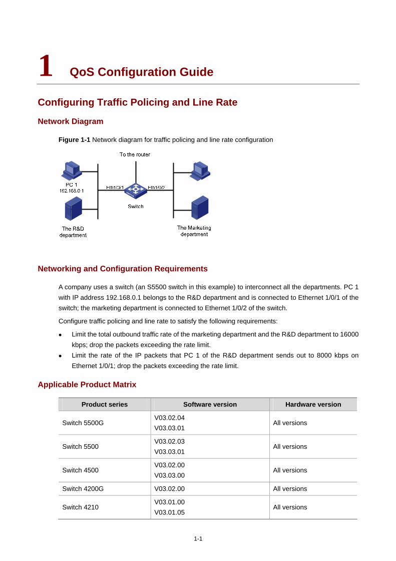
1-1
1 QoS Configuration Guide
Configuring Traffic Policing and Line Rate
Network Diagram
Figure 1-1 Network diagram for traffic policing and line rate configuration
Networking and Configuration Requirements
A company uses a switch (an S5500 switch in this example) to interconnect all the departments. PC 1 with IP address 192.168.0.1 belongs to the R&D department and is connected to Ethernet 1/0/1 of the switch; the marketing department is connected to Ethernet 1/0/2 of the switch.
Configure traffic policing and line rate to satisfy the following requirements:
Limit the total outbound traffic rate of the marketing department and the R&D department to 16000 kbps; drop the packets exceeding the rate limit.
Limit the rate of the IP packets that PC 1 of the R&D department sends out to 8000 kbps on Ethernet 1/0/1; drop the packets exceeding the rate limit.
Applicable Product Matrix
Product series Software version Hardware version
Switch 5500G V03.02.04 V03.03.01
All versions
Switch 5500 V03.02.03 V03.03.01
All versions
Switch 4500 V03.02.00 V03.03.00
All versions
Switch 4200G V03.02.00 All versions
Switch 4210 V03.01.00 V03.01.05
All versions
1-2
The S4210 series do not support traffic policing. The S4200G series do not support line rate.
Configuration Procedure
1) Define traffic classification rules
# Create basic ACL 2000 and enter basic ACL view.
<Sysname> system-view
[Sysname] acl number 2000
# Define a rule to match the packets with source IP address 192.168.0.1.
[Sysname-acl-basic-2000] rule permit source 192.168.0.1 0
[Sysname-acl-basic-2000] quit
2) Configure traffic policing and line rate
# Limit the total outbound traffic rate of the marketing department and the R&D department to 16000 kbps, and drop the packets exceeding the rate limit.
[Sysname] interface Ethernet 1/0/3
[Sysname-Ethernet1/0/3] line-rate outbound 16000
# Limit the rate of the IP packets that PC 1 of the R&D department sends out to 8000 kbps, and drop the packets exceeding the rate limit.
[Sysname] interface Ethernet 1/0/1
[Sysname-Ethernet1/0/1] traffic-limit inbound ip-group 2000 8000 exceed drop
Complete Configuration
#
acl number 2000
rule 0 permit source 192.168.0.1 0
#
interface Ethernet1/0/1
traffic-limit inbound ip-group 2000 rule 0 8000 exceed drop
#
interface Ethernet1/0/3
line-rate outbound 16000
#
Precautions
Note that:
The ACL rules configured for traffic classification must be permit statements. If packets match ACL rules of multiple traffic policing actions, the traffic policing action issued the
last takes effect.
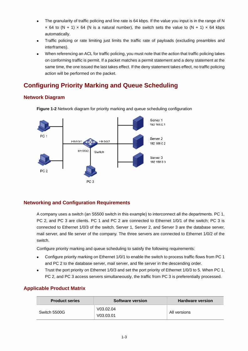
1-3
The granularity of traffic policing and line rate is 64 kbps. If the value you input is in the range of N × 64 to (N + 1) × 64 (N is a natural number), the switch sets the value to (N + 1) × 64 kbps automatically.
Traffic policing or rate limiting just limits the traffic rate of payloads (excluding preambles and interframes).
When referencing an ACL for traffic policing, you must note that the action that traffic policing takes on conforming traffic is permit. If a packet matches a permit statement and a deny statement at the same time, the one issued the last takes effect. If the deny statement takes effect, no traffic policing action will be performed on the packet.
Configuring Priority Marking and Queue Scheduling
Network Diagram
Figure 1-2 Network diagram for priority marking and queue scheduling configuration
Networking and Configuration Requirements
A company uses a switch (an S5500 switch in this example) to interconnect all the departments. PC 1, PC 2, and PC 3 are clients. PC 1 and PC 2 are connected to Ethernet 1/0/1 of the switch; PC 3 is connected to Ethernet 1/0/3 of the switch. Server 1, Server 2, and Server 3 are the database server, mail server, and file server of the company. The three servers are connected to Ethernet 1/0/2 of the switch.
Configure priority marking and queue scheduling to satisfy the following requirements:
Configure priority marking on Ethernet 1/0/1 to enable the switch to process traffic flows from PC 1 and PC 2 to the database server, mail server, and file server in the descending order.
Trust the port priority on Ethernet 1/0/3 and set the port priority of Ethernet 1/0/3 to 5. When PC 1, PC 2, and PC 3 access servers simultaneously, the traffic from PC 3 is preferentially processed.
Applicable Product Matrix
Product series Software version Hardware version
Switch 5500G V03.02.04 V03.03.01
All versions
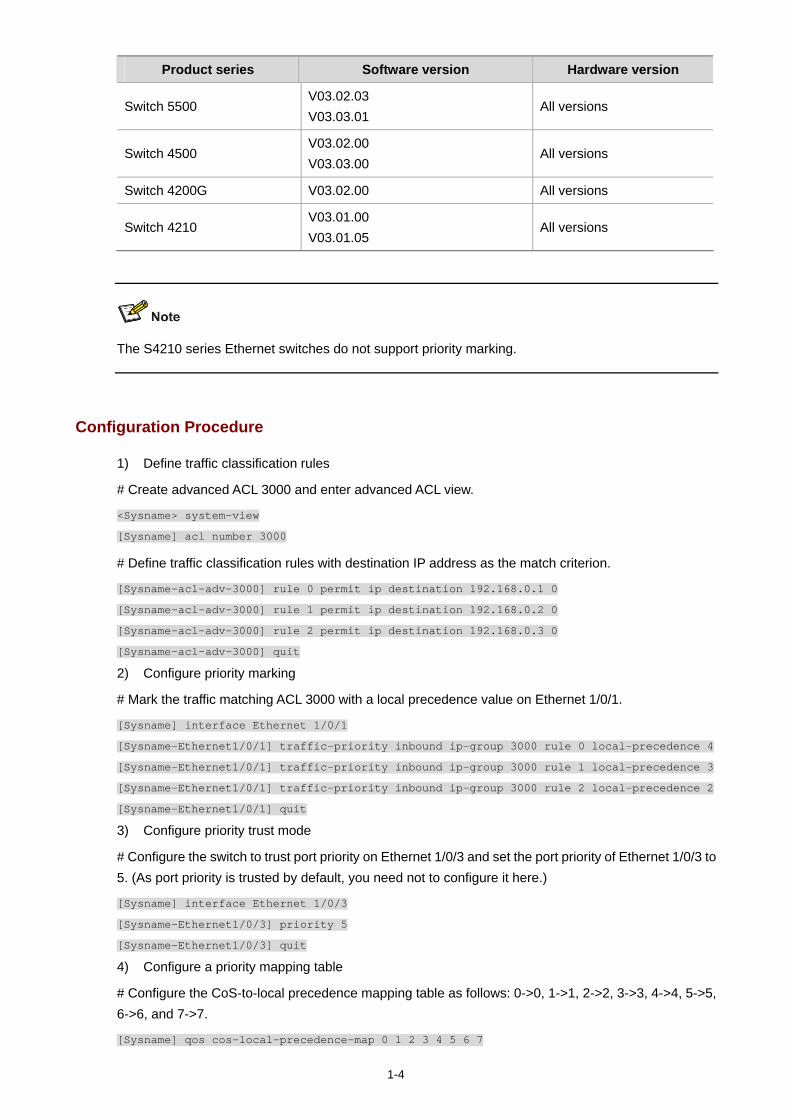
1-4
Product series Software version Hardware version
Switch 5500 V03.02.03 V03.03.01
All versions
Switch 4500 V03.02.00 V03.03.00
All versions
Switch 4200G V03.02.00 All versions
Switch 4210 V03.01.00 V03.01.05
All versions
The S4210 series Ethernet switches do not support priority marking.
Configuration Procedure
1) Define traffic classification rules
# Create advanced ACL 3000 and enter advanced ACL view.
<Sysname> system-view
[Sysname] acl number 3000
# Define traffic classification rules with destination IP address as the match criterion.
[Sysname-acl-adv-3000] rule 0 permit ip destination 192.168.0.1 0
[Sysname-acl-adv-3000] rule 1 permit ip destination 192.168.0.2 0
[Sysname-acl-adv-3000] rule 2 permit ip destination 192.168.0.3 0
[Sysname-acl-adv-3000] quit
2) Configure priority marking
# Mark the traffic matching ACL 3000 with a local precedence value on Ethernet 1/0/1.
[Sysname] interface Ethernet 1/0/1
[Sysname-Ethernet1/0/1] traffic-priority inbound ip-group 3000 rule 0 local-precedence 4
[Sysname-Ethernet1/0/1] traffic-priority inbound ip-group 3000 rule 1 local-precedence 3
[Sysname-Ethernet1/0/1] traffic-priority inbound ip-group 3000 rule 2 local-precedence 2
[Sysname-Ethernet1/0/1] quit
3) Configure priority trust mode
# Configure the switch to trust port priority on Ethernet 1/0/3 and set the port priority of Ethernet 1/0/3 to 5. (As port priority is trusted by default, you need not to configure it here.)
[Sysname] interface Ethernet 1/0/3
[Sysname-Ethernet1/0/3] priority 5
[Sysname-Ethernet1/0/3] quit
4) Configure a priority mapping table
# Configure the CoS-to-local precedence mapping table as follows: 0->0, 1->1, 2->2, 3->3, 4->4, 5->5, 6->6, and 7->7.
[Sysname] qos cos-local-precedence-map 0 1 2 3 4 5 6 7
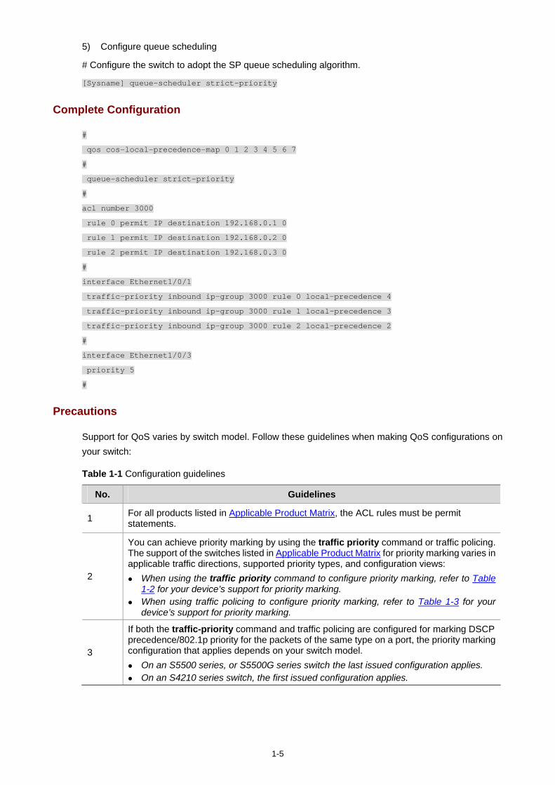
1-5
5) Configure queue scheduling
# Configure the switch to adopt the SP queue scheduling algorithm.
[Sysname] queue-scheduler strict-priority
Complete Configuration
#
qos cos-local-precedence-map 0 1 2 3 4 5 6 7
#
queue-scheduler strict-priority
#
acl number 3000
rule 0 permit IP destination 192.168.0.1 0
rule 1 permit IP destination 192.168.0.2 0
rule 2 permit IP destination 192.168.0.3 0
#
interface Ethernet1/0/1
traffic-priority inbound ip-group 3000 rule 0 local-precedence 4
traffic-priority inbound ip-group 3000 rule 1 local-precedence 3
traffic-priority inbound ip-group 3000 rule 2 local-precedence 2
#
interface Ethernet1/0/3
priority 5
#
Precautions
Support for QoS varies by switch model. Follow these guidelines when making QoS configurations on your switch:
Table 1-1 Configuration guidelines
No. Guidelines
1 For all products listed in Applicable Product Matrix, the ACL rules must be permit statements.
2
You can achieve priority marking by using the traffic priority command or traffic policing. The support of the switches listed in Applicable Product Matrix for priority marking varies in applicable traffic directions, supported priority types, and configuration views:
When using the traffic priority command to configure priority marking, refer to Table 1-2 for your device’s support for priority marking.
When using traffic policing to configure priority marking, refer to Table 1-3 for your device’s support for priority marking.
3
If both the traffic-priority command and traffic policing are configured for marking DSCP precedence/802.1p priority for the packets of the same type on a port, the priority marking configuration that applies depends on your switch model.
On an S5500 series, or S5500G series switch the last issued configuration applies. On an S4210 series switch, the first issued configuration applies.
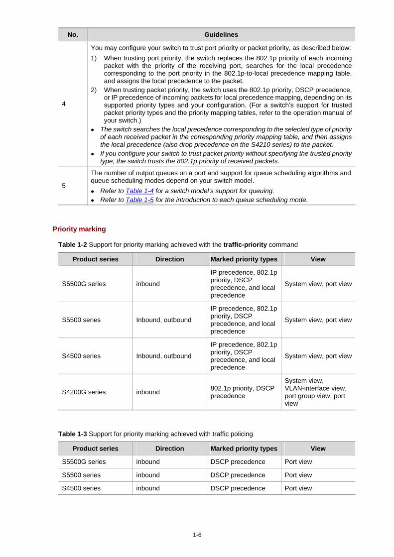
1-6
No. Guidelines
4
You may configure your switch to trust port priority or packet priority, as described below:1) When trusting port priority, the switch replaces the 802.1p priority of each incoming
packet with the priority of the receiving port, searches for the local precedence corresponding to the port priority in the 802.1p-to-local precedence mapping table, and assigns the local precedence to the packet.
2) When trusting packet priority, the switch uses the 802.1p priority, DSCP precedence, or IP precedence of incoming packets for local precedence mapping, depending on its supported priority types and your configuration. (For a switch’s support for trusted packet priority types and the priority mapping tables, refer to the operation manual of your switch.)
The switch searches the local precedence corresponding to the selected type of priority of each received packet in the corresponding priority mapping table, and then assigns the local precedence (also drop precedence on the S4210 series) to the packet.
If you configure your switch to trust packet priority without specifying the trusted priority type, the switch trusts the 802.1p priority of received packets.
5
The number of output queues on a port and support for queue scheduling algorithms and queue scheduling modes depend on your switch model.
Refer to Table 1-4 for a switch model’s support for queuing. Refer to Table 1-5 for the introduction to each queue scheduling mode.
Priority marking
Table 1-2 Support for priority marking achieved with the traffic-priority command
Product series Direction Marked priority types View
S5500G series inbound
IP precedence, 802.1p priority, DSCP precedence, and local precedence
System view, port view
S5500 series Inbound, outbound
IP precedence, 802.1p priority, DSCP precedence, and local precedence
System view, port view
S4500 series Inbound, outbound
IP precedence, 802.1p priority, DSCP precedence, and local precedence
System view, port view
S4200G series inbound 802.1p priority, DSCP precedence
System view, VLAN-interface view, port group view, port view
Table 1-3 Support for priority marking achieved with traffic policing
Product series Direction Marked priority types View
S5500G series inbound DSCP precedence Port view
S5500 series inbound DSCP precedence Port view
S4500 series inbound DSCP precedence Port view
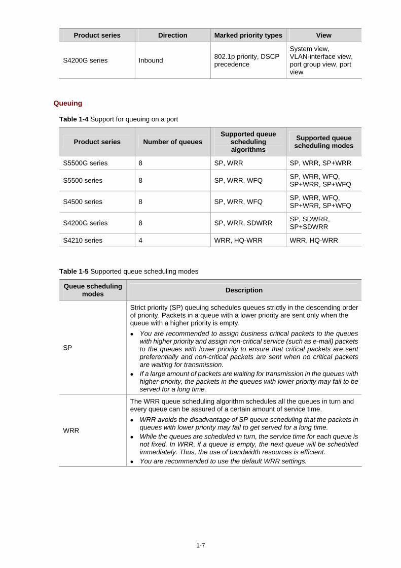
1-7
Product series Direction Marked priority types View
S4200G series Inbound 802.1p priority, DSCP precedence
System view, VLAN-interface view, port group view, port view
Queuing
Table 1-4 Support for queuing on a port
Product series Number of queues Supported queue
scheduling algorithms
Supported queue scheduling modes
S5500G series 8 SP, WRR SP, WRR, SP+WRR
S5500 series 8 SP, WRR, WFQ SP, WRR, WFQ, SP+WRR, SP+WFQ
S4500 series 8 SP, WRR, WFQ SP, WRR, WFQ, SP+WRR, SP+WFQ
S4200G series 8 SP, WRR, SDWRR SP, SDWRR, SP+SDWRR
S4210 series 4 WRR, HQ-WRR WRR, HQ-WRR
Table 1-5 Supported queue scheduling modes
Queue scheduling modes Description
SP
Strict priority (SP) queuing schedules queues strictly in the descending order of priority. Packets in a queue with a lower priority are sent only when the queue with a higher priority is empty.
You are recommended to assign business critical packets to the queues with higher priority and assign non-critical service (such as e-mail) packets to the queues with lower priority to ensure that critical packets are sent preferentially and non-critical packets are sent when no critical packets are waiting for transmission.
If a large amount of packets are waiting for transmission in the queues with higher-priority, the packets in the queues with lower priority may fail to be served for a long time.
WRR
The WRR queue scheduling algorithm schedules all the queues in turn and every queue can be assured of a certain amount of service time.
WRR avoids the disadvantage of SP queue scheduling that the packets in queues with lower priority may fail to get served for a long time.
While the queues are scheduled in turn, the service time for each queue is not fixed. In WRR, if a queue is empty, the next queue will be scheduled immediately. Thus, the use of bandwidth resources is efficient.
You are recommended to use the default WRR settings.
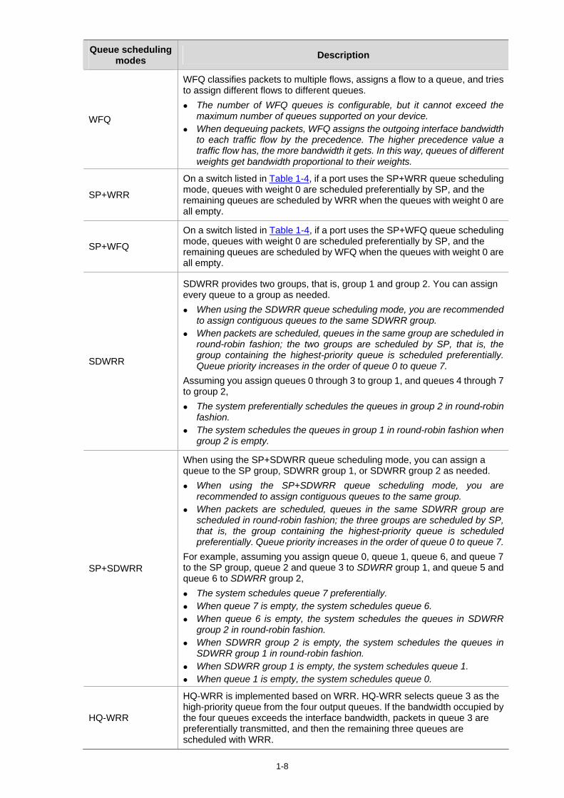
1-8
Queue scheduling modes Description
WFQ
WFQ classifies packets to multiple flows, assigns a flow to a queue, and tries to assign different flows to different queues.
The number of WFQ queues is configurable, but it cannot exceed the maximum number of queues supported on your device.
When dequeuing packets, WFQ assigns the outgoing interface bandwidth to each traffic flow by the precedence. The higher precedence value a traffic flow has, the more bandwidth it gets. In this way, queues of different weights get bandwidth proportional to their weights.
SP+WRR
On a switch listed in Table 1-4, if a port uses the SP+WRR queue scheduling mode, queues with weight 0 are scheduled preferentially by SP, and the remaining queues are scheduled by WRR when the queues with weight 0 are all empty.
SP+WFQ
On a switch listed in Table 1-4, if a port uses the SP+WFQ queue scheduling mode, queues with weight 0 are scheduled preferentially by SP, and the remaining queues are scheduled by WFQ when the queues with weight 0 are all empty.
SDWRR
SDWRR provides two groups, that is, group 1 and group 2. You can assign every queue to a group as needed.
When using the SDWRR queue scheduling mode, you are recommended to assign contiguous queues to the same SDWRR group.
When packets are scheduled, queues in the same group are scheduled in round-robin fashion; the two groups are scheduled by SP, that is, the group containing the highest-priority queue is scheduled preferentially. Queue priority increases in the order of queue 0 to queue 7.
Assuming you assign queues 0 through 3 to group 1, and queues 4 through 7 to group 2,
The system preferentially schedules the queues in group 2 in round-robin fashion.
The system schedules the queues in group 1 in round-robin fashion when group 2 is empty.
SP+SDWRR
When using the SP+SDWRR queue scheduling mode, you can assign a queue to the SP group, SDWRR group 1, or SDWRR group 2 as needed.
When using the SP+SDWRR queue scheduling mode, you are recommended to assign contiguous queues to the same group.
When packets are scheduled, queues in the same SDWRR group are scheduled in round-robin fashion; the three groups are scheduled by SP, that is, the group containing the highest-priority queue is scheduled preferentially. Queue priority increases in the order of queue 0 to queue 7.
For example, assuming you assign queue 0, queue 1, queue 6, and queue 7 to the SP group, queue 2 and queue 3 to SDWRR group 1, and queue 5 and queue 6 to SDWRR group 2,
The system schedules queue 7 preferentially. When queue 7 is empty, the system schedules queue 6. When queue 6 is empty, the system schedules the queues in SDWRR
group 2 in round-robin fashion. When SDWRR group 2 is empty, the system schedules the queues in
SDWRR group 1 in round-robin fashion. When SDWRR group 1 is empty, the system schedules queue 1. When queue 1 is empty, the system schedules queue 0.
HQ-WRR
HQ-WRR is implemented based on WRR. HQ-WRR selects queue 3 as the high-priority queue from the four output queues. If the bandwidth occupied by the four queues exceeds the interface bandwidth, packets in queue 3 are preferentially transmitted, and then the remaining three queues are scheduled with WRR.
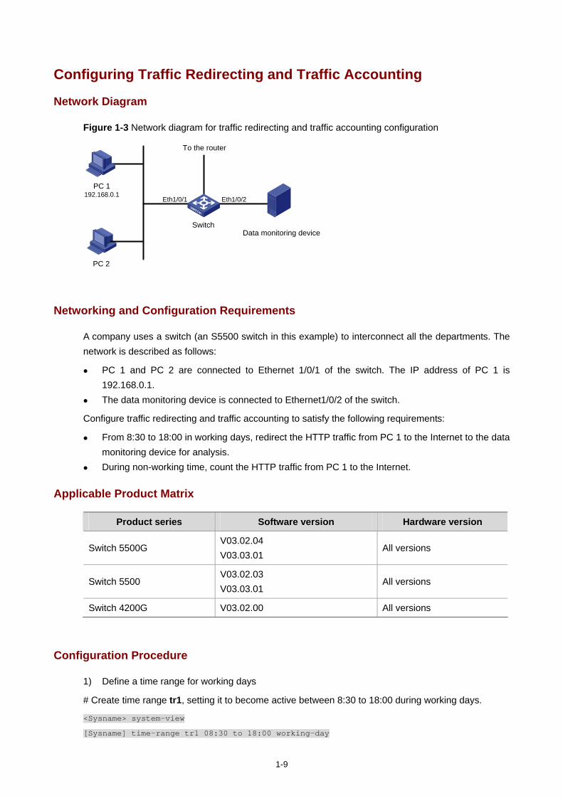
1-9
Configuring Traffic Redirecting and Traffic Accounting
Network Diagram
Figure 1-3 Network diagram for traffic redirecting and traffic accounting configuration
Switch Data monitoring device
Eth1/0/2
PC 2
PC 1192.168.0.1
Eth1/0/1
To the router
Networking and Configuration Requirements
A company uses a switch (an S5500 switch in this example) to interconnect all the departments. The network is described as follows:
PC 1 and PC 2 are connected to Ethernet 1/0/1 of the switch. The IP address of PC 1 is 192.168.0.1.
The data monitoring device is connected to Ethernet1/0/2 of the switch.
Configure traffic redirecting and traffic accounting to satisfy the following requirements:
From 8:30 to 18:00 in working days, redirect the HTTP traffic from PC 1 to the Internet to the data monitoring device for analysis.
During non-working time, count the HTTP traffic from PC 1 to the Internet.
Applicable Product Matrix
Product series Software version Hardware version
Switch 5500G V03.02.04 V03.03.01
All versions
Switch 5500 V03.02.03 V03.03.01
All versions
Switch 4200G V03.02.00 All versions
Configuration Procedure
1) Define a time range for working days
# Create time range tr1, setting it to become active between 8:30 to 18:00 during working days.
<Sysname> system-view
[Sysname] time-range tr1 08:30 to 18:00 working-day
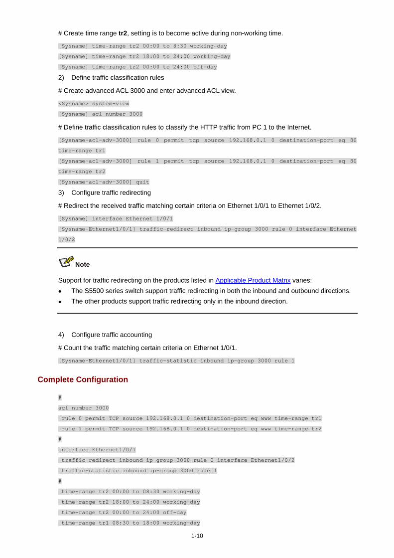
1-10
# Create time range tr2, setting is to become active during non-working time.
[Sysname] time-range tr2 00:00 to 8:30 working-day
[Sysname] time-range tr2 18:00 to 24:00 working-day
[Sysname] time-range tr2 00:00 to 24:00 off-day
2) Define traffic classification rules
# Create advanced ACL 3000 and enter advanced ACL view.
<Sysname> system-view
[Sysname] acl number 3000
# Define traffic classification rules to classify the HTTP traffic from PC 1 to the Internet.
[Sysname-acl-adv-3000] rule 0 permit tcp source 192.168.0.1 0 destination-port eq 80
time-range tr1
[Sysname-acl-adv-3000] rule 1 permit tcp source 192.168.0.1 0 destination-port eq 80
time-range tr2
[Sysname-acl-adv-3000] quit
3) Configure traffic redirecting
# Redirect the received traffic matching certain criteria on Ethernet 1/0/1 to Ethernet 1/0/2.
[Sysname] interface Ethernet 1/0/1
[Sysname-Ethernet1/0/1] traffic-redirect inbound ip-group 3000 rule 0 interface Ethernet
1/0/2
Support for traffic redirecting on the products listed in Applicable Product Matrix varies: The S5500 series switch support traffic redirecting in both the inbound and outbound directions. The other products support traffic redirecting only in the inbound direction.
4) Configure traffic accounting
# Count the traffic matching certain criteria on Ethernet 1/0/1.
[Sysname-Ethernet1/0/1] traffic-statistic inbound ip-group 3000 rule 1
Complete Configuration
#
acl number 3000
rule 0 permit TCP source 192.168.0.1 0 destination-port eq www time-range tr1
rule 1 permit TCP source 192.168.0.1 0 destination-port eq www time-range tr2
#
interface Ethernet1/0/1
traffic-redirect inbound ip-group 3000 rule 0 interface Ethernet1/0/2
traffic-statistic inbound ip-group 3000 rule 1
#
time-range tr2 00:00 to 08:30 working-day
time-range tr2 18:00 to 24:00 working-day
time-range tr2 00:00 to 24:00 off-day
time-range tr1 08:30 to 18:00 working-day

1-11
#
Precautions
Note that:
The ACL rules configured for traffic classification must be permit statements. When redirecting a packet, the switch processes the packet with the forwarding mechanism
instead of leaving it intact. With traffic redirecting configured, the switch does not forward the packets to be redirected as
usual. The packets received on the destination port for redirection are tagged.
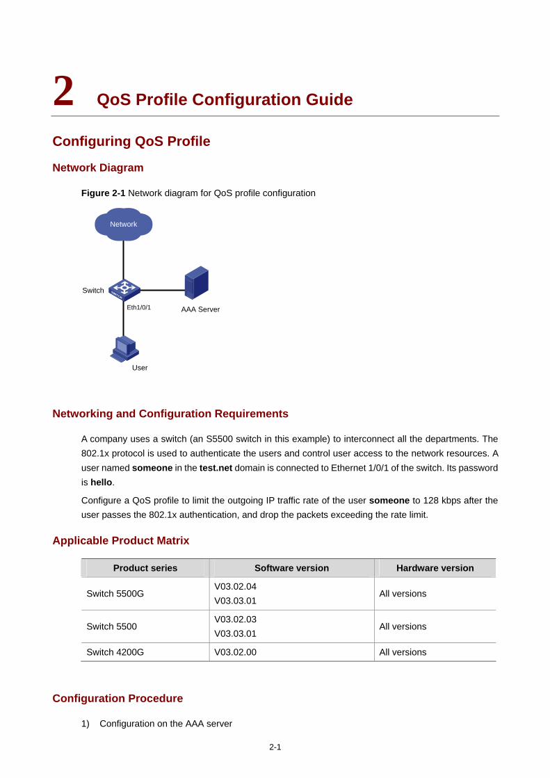
2-1
2 QoS Profile Configuration Guide
Configuring QoS Profile
Network Diagram
Figure 2-1 Network diagram for QoS profile configuration
User
Switch
Network
AAA ServerEth1/0/1
Networking and Configuration Requirements
A company uses a switch (an S5500 switch in this example) to interconnect all the departments. The 802.1x protocol is used to authenticate the users and control user access to the network resources. A user named someone in the test.net domain is connected to Ethernet 1/0/1 of the switch. Its password is hello.
Configure a QoS profile to limit the outgoing IP traffic rate of the user someone to 128 kbps after the user passes the 802.1x authentication, and drop the packets exceeding the rate limit.
Applicable Product Matrix
Product series Software version Hardware version
Switch 5500G V03.02.04 V03.03.01
All versions
Switch 5500 V03.02.03 V03.03.01
All versions
Switch 4200G V03.02.00 All versions
Configuration Procedure
1) Configuration on the AAA server
2-2
Configure authentication information and user name-to-QoS-profile mapping for the user on the AAA server. Refer to the guide to AAA Server configuration for detailed information.
2) Configuration on the switch
# Configure the IP address information of the RADIUS server as 10.11.1.1.
<Sysname> system-view
[Sysname] radius scheme radius1
[Sysname-radius-radius1] primary authentication 10.11.1.1
[Sysname-radius-radius1] primary accounting 10.11.1.1
# Configure the encryption keys as money for the switch to exchange packets with the authentication RADIUS server and the accounting RADIUS server.
[Sysname-radius-radius1] key authentication money
[Sysname-radius-radius1] key accounting money
# Enable the switch to remove the domain name from the fully qualified user name and then send the unqualified user name to the RADIUS sever.
[Sysname-radius-radius1] user-name-format without-domain
[Sysname-radius-radius1] quit
# Create the user domain test.net and specify radius1 as the RADIUS server group for the domain user.
[Sysname] domain test.net
[Sysname-isp-test.net] radius-scheme radius1
[Sysname-isp-test.net] quit
# Create advanced ACL 3000 and define a classification rule to match IP packets destined for any IP address.
[Sysname] acl number 3000
[Sysname-acl-adv-3000] rule 1 permit ip destination any
[Sysname-acl-adv-3000] quit
# Configure a QoS profile to limit the rate of the conforming traffic to 128 kbps and drop the packets exceeding the rate limit.
[Sysname] qos-profile example
[Sysname-qos-profile-example] traffic-limit inbound ip-group 3000 128 exceed drop
# Enable 802.1x.
[Sysname] dot1x
[Sysname] dot1x interface Ethernet 1/0/1
Complete Configuration
#
dot1x
#
radius scheme system
radius scheme radius1
server-type standard
primary authentication 10.11.1.1
primary accounting 10.11.1.1
key authentication money
2-3
key accounting money
user-name-format without-domain
#
domain system
domain test.net
scheme radius-scheme radius1
#
acl number 3000
rule 0 permit IP
#
qos-profile example
traffic-limit inbound ip-group 3000 rule 0 128 exceed drop
#
interface Ethernet1/0/1
dot1x
#
Precautions
Note that:
A QoS profile can be applied manually or dynamically. You can use the apply qos-profile profile-name command to manually apply a QoS profile to a port. You can also combine a QoS profile with the 802.1x authentication function to provide the pre-defined QoS function for a user or a group of users that have passed authentication.
Depending on the 802.1x authentication mode, dynamic QoS profile application mode can be user-based or port-based. The user-based mode is the default mode.
If the traffic classification rules of a QoS profile take source information (including source MAC, source IP, VLAN) as the match criterion, the QoS profile cannot be applied in the user-based mode.
Currently, the QoS profile function provides packet filtering, traffic policing, and priority marking. The granularity of traffic policing is 64 kbps. If the value you input is in the range of N × 64 to (N + 1)
× 64 (where N is a natural number), the switch sets the value to (N + 1) × 64 kbps automatically.

i
Table of Contents
1 Web Cache Redirection Configuration Guide ························································································1-1 Configuring Web Cache Redirection·······································································································1-1
Network Diagram·····························································································································1-1 Networking and Configuration Requirements··················································································1-1 Applicable Product Matrix················································································································1-2 Configuration Procedure··················································································································1-2 Complete Configuration···················································································································1-3 Precautions······································································································································1-4
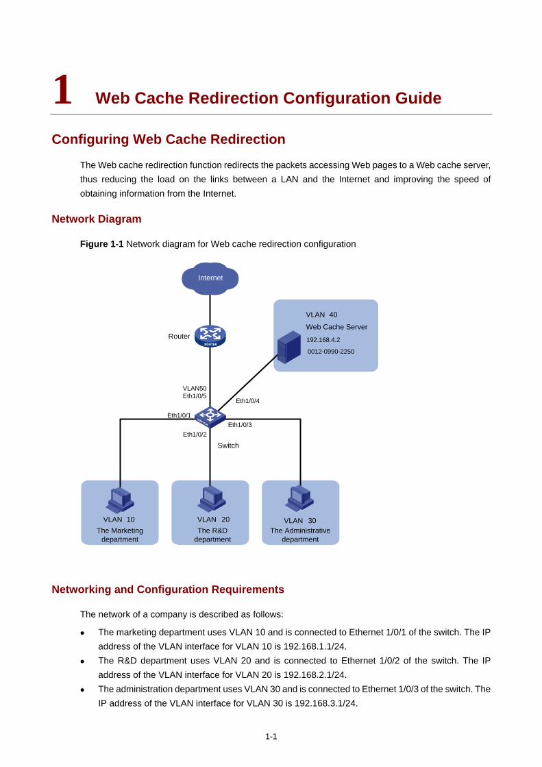
1-1
1 Web Cache Redirection Configuration Guide
Configuring Web Cache Redirection
The Web cache redirection function redirects the packets accessing Web pages to a Web cache server, thus reducing the load on the links between a LAN and the Internet and improving the speed of obtaining information from the Internet.
Network Diagram
Figure 1-1 Network diagram for Web cache redirection configuration
The Marketing department
The R&D department
The Administrative department
Web Cache Server
VLAN 40
VLAN 10 VLAN 20 VLAN 30
Eth1/0/1Eth1/0/3
Eth1/0/2
Eth1/0/4
192.168.4.2
0012-0990-2250
VLAN50Eth1/0/5
Router
Switch
Internet
Networking and Configuration Requirements
The network of a company is described as follows:
The marketing department uses VLAN 10 and is connected to Ethernet 1/0/1 of the switch. The IP address of the VLAN interface for VLAN 10 is 192.168.1.1/24.
The R&D department uses VLAN 20 and is connected to Ethernet 1/0/2 of the switch. The IP address of the VLAN interface for VLAN 20 is 192.168.2.1/24.
The administration department uses VLAN 30 and is connected to Ethernet 1/0/3 of the switch. The IP address of the VLAN interface for VLAN 30 is 192.168.3.1/24.
1-2
The Web cache server belongs to VLAN 40 and is connected to Ethernet 1/0/4 of the switch. The IP address of the VLAN interface for VLAN 40 is 192.168.4.1/24. The IP address and the MAC address of the Web cache server is 192.168.4.2 and 0012-0990-2250.
The router is connected to Ethernet 1/0/5 of the switch. The switch accesses the Internet through a router. Ethernet 1/0/5 belongs to VLAN 50 whose VLAN interface is assigned IP address 192.168.5.1/24.
Enable Web cache redirection on the switch to redirect all the HTTP packets of the three departments to the Web cache server, thus reducing the load on the WAN link and improving the speed of obtaining information from the Internet.
Applicable Product Matrix
Product series Software version Hardware version
Switch 5500 V03.02.03 V03.03.01
All versions
Configuration Procedure
# Create VLAN 10 for the marketing department and configure the IP address of VLAN-interface 10 as 192.168.1.1.
<Sysname> system-view
[Sysname] vlan 10
[Sysname-vlan10] port Ethernet 1/0/1
[Sysname-vlan10] quit
[Sysname] interface Vlan-interface 10
[Sysname-Vlan-interface10] ip address 192.168.1.1 24
[Sysname-Vlan-interface10] quit
# Create VLAN 20 for the R&D department and configure the IP address of VLAN-interface 20 as 192.168.2.1.
[Sysname] vlan 20
[Sysname-vlan20] port Ethernet 1/0/2
[Sysname-vlan20] quit
[Sysname] interface Vlan-interface 20
[Sysname-Vlan-interface20] ip address 192.168.2.1 24
[Sysname-Vlan-interface20] quit
# Create VLAN 30 for the administration department and configure the IP address of VLAN-interface 30 as 192.168.3.1.
[Sysname] vlan 30
[Sysname-vlan30] port Ethernet 1/0/3
[Sysname-vlan30] quit
[Sysname] interface Vlan-interface 30
[Sysname-Vlan-interface30] ip address 192.168.3.1 24
[Sysname-Vlan-interface30] quit
# Create VLAN 40 for the Web cache server and configure the IP address of VLAN-interface 40 as 192.168.4.1.
1-3
[Sysname] vlan 40
[Sysname-vlan40] port Ethernet 1/0/4
[Sysname-vlan40] quit
[Sysname] interface Vlan-interface 40
[Sysname-Vlan-interface40] ip address 192.168.4.1 24
[Sysname-Vlan-interface40] quit
# Create VLAN 50 for the switch to connect to the router and configure the IP address of VLAN-interface 50 as 192.168.5.1.
[Sysname] vlan 50
[Sysname-vlan50] port Ethernet 1/0/5
[Sysname-vlan50] quit
[Sysname] interface Vlan-interface 50
[Sysname-Vlan-interface50] ip address 192.168.5.1 24
[Sysname-Vlan-interface50] quit
# Configure Ethernet 1/0/4, the port connected to the Web cache server, as a trunk port, and configure the port to permit the packets of VLAN 40 and VLAN 50 to pass through.
[Sysname] interface Ethernet 1/0/4
[Sysname-Ethernet1/0/4] port link-type trunk
[Sysname-Ethernet1/0/4] port trunk permit vlan 40 50
[Sysname-Ethernet1/0/4] quit
# Enable Web cache redirection to redirect all the HTTP packets received from VLAN 10, VLAN 20, and VLAN 30 to the Web cache server.
[Sysname] webcache address 192.168.4.2 mac 0012-0990-2250 vlan 40 port Ethernet 1/0/4
[Sysname] webcache redirect-vlan 10
[Sysname] webcache redirect-vlan 20
[Sysname] webcache redirect-vlan 30
Complete Configuration
#
vlan 10
#
vlan 20
#
vlan 30
#
vlan 40
#
vlan 50
#
interface Vlan-interface10
ip address 192.168.1.1 255.255.255.0
#
interface Vlan-interface20
ip address 192.168.2.1 255.255.255.0
#
interface Vlan-interface30
1-4
ip address 192.168.3.1 255.255.255.0
#
interface Vlan-interface40
ip address 192.168.4.1 255.255.255.0
#
interface Vlan-interface50
ip address 192.168.5.1 255.255.255.0
#
interface Ethernet1/0/1
port access vlan 10
#
interface Ethernet1/0/2
port access vlan 20
#
interface Ethernet1/0/3
port access vlan 30
#
interface Ethernet1/0/4
port link-type trunk
port trunk permit vlan 1 40 50
webcache address 192.168.4.2 mac 0012-0990-2250 vlan 40
#
interface Ethernet1/0/5
port access vlan 50
#
webcache redirect-vlan 10
webcache redirect-vlan 20
webcache redirect-vlan 30
#
Precautions
When configuring Web cache redirection, consider the following:
To ensure the success of Web cache redirection, check that the VLAN-interfaces for all the involved VLANs (VLAN 40, VLAN 10, VLAN 20, and VLAN 30) are up.
Do not redirect the HTTP packets destined for VLAN 40 to the Web cache server. Enabling STP can cause Web cache redirection failure.

i
Table of Contents
1 Mirroring Configuration ····························································································································1-1 Local Port Mirroring Configuration ··········································································································1-1
Network Diagram·····························································································································1-1 Networking and Configuration Requirements··················································································1-1 Applicable Product Matrix················································································································1-1 Configuration Procedure··················································································································1-2 Complete Configuration···················································································································1-2 Precautions······································································································································1-2
Remote Port Mirroring Configuration ······································································································1-3 Network Diagram·····························································································································1-4 Networking and Configuration Requirements··················································································1-4 Applicable Product Matrix················································································································1-4 Configuration Procedure··················································································································1-5 Complete Configuration···················································································································1-6 Precautions······································································································································1-7
Traffic Mirroring Configuration ················································································································1-8 Network Diagram·····························································································································1-8 Networking and Configuration Requirements··················································································1-8 Applicable Product Matrix················································································································1-8 Configuration Procedure··················································································································1-9 Complete Configuration···················································································································1-9 Precautions······································································································································1-9
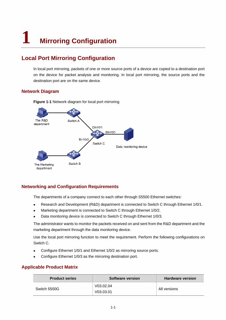
1-1
1 Mirroring Configuration
Local Port Mirroring Configuration
In local port mirroring, packets of one or more source ports of a device are copied to a destination port on the device for packet analysis and monitoring. In local port mirroring, the source ports and the destination port are on the same device.
Network Diagram
Figure 1-1 Network diagram for local port mirroring
Networking and Configuration Requirements
The departments of a company connect to each other through S5500 Ethernet switches:
Research and Development (R&D) department is connected to Switch C through Ethernet 1/0/1. Marketing department is connected to Switch C through Ethernet 1/0/2. Data monitoring device is connected to Switch C through Ethernet 1/0/3.
The administrator wants to monitor the packets received on and sent from the R&D department and the marketing department through the data monitoring device.
Use the local port mirroring function to meet the requirement. Perform the following configurations on Switch C.
Configure Ethernet 1/0/1 and Ethernet 1/0/2 as mirroring source ports. Configure Ethernet 1/0/3 as the mirroring destination port.
Applicable Product Matrix
Product series Software version Hardware version
Switch 5500G V03.02.04 V03.03.01
All versions
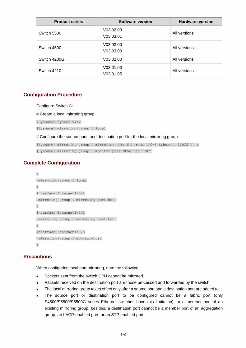
1-2
Product series Software version Hardware version
Switch 5500 V03.02.03 V03.03.01
All versions
Switch 4500 V03.02.00 V03.03.00
All versions
Switch 4200G V03.02.00 All versions
Switch 4210 V03.01.00 V03.01.05
All versions
Configuration Procedure
Configure Switch C:
# Create a local mirroring group.
<Sysname> system-view
[Sysname] mirroring-group 1 local
# Configure the source ports and destination port for the local mirroring group.
[Sysname] mirroring-group 1 mirroring-port Ethernet 1/0/1 Ethernet 1/0/2 both
[Sysname] mirroring-group 1 monitor-port Ethernet 1/0/3
Complete Configuration
#
mirroring-group 1 local
#
interface Ethernet1/0/1
mirroring-group 1 mirroring-port both
#
interface Ethernet1/0/2
mirroring-group 1 mirroring-port both
#
interface Ethernet1/0/3
mirroring-group 1 monitor-port
#
Precautions
When configuring local port mirroring, note the following:
Packets sent from the switch CPU cannot be mirrored. Packets received on the destination port are those processed and forwarded by the switch. The local mirroring group takes effect only after a source port and a destination port are added to it. The source port or destination port to be configured cannot be a fabric port (only
S4500/S5500/S5500G series Ethernet switches have this limitation), or a member port of an existing mirroring group; besides, a destination port cannot be a member port of an aggregation group, an LACP-enabled port, or an STP enabled port.
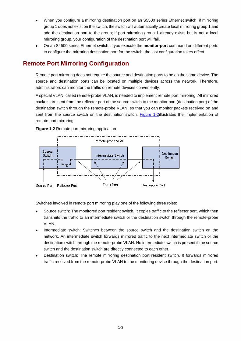
1-3
When you configure a mirroring destination port on an S5500 series Ethernet switch, if mirroring group 1 does not exist on the switch, the switch will automatically create local mirroring group 1 and add the destination port to the group; if port mirroring group 1 already exists but is not a local mirroring group, your configuration of the destination port will fail.
On an S4500 series Ethernet switch, if you execute the monitor-port command on different ports to configure the mirroring destination port for the switch, the last configuration takes effect.
Remote Port Mirroring Configuration
Remote port mirroring does not require the source and destination ports to be on the same device. The source and destination ports can be located on multiple devices across the network. Therefore, administrators can monitor the traffic on remote devices conveniently.
A special VLAN, called remote-probe VLAN, is needed to implement remote port mirroring. All mirrored packets are sent from the reflector port of the source switch to the monitor port (destination port) of the destination switch through the remote-probe VLAN, so that you can monitor packets received on and sent from the source switch on the destination switch. Figure 1-2illustrates the implementation of remote port mirroring.
Figure 1-2 Remote port mirroring application
Switches involved in remote port mirroring play one of the following three roles:
Source switch: The monitored port resident switch. It copies traffic to the reflector port, which then transmits the traffic to an intermediate switch or the destination switch through the remote-probe VLAN.
Intermediate switch: Switches between the source switch and the destination switch on the network. An intermediate switch forwards mirrored traffic to the next intermediate switch or the destination switch through the remote-probe VLAN. No intermediate switch is present if the source switch and the destination switch are directly connected to each other.
Destination switch: The remote mirroring destination port resident switch. It forwards mirrored traffic received from the remote-probe VLAN to the monitoring device through the destination port.
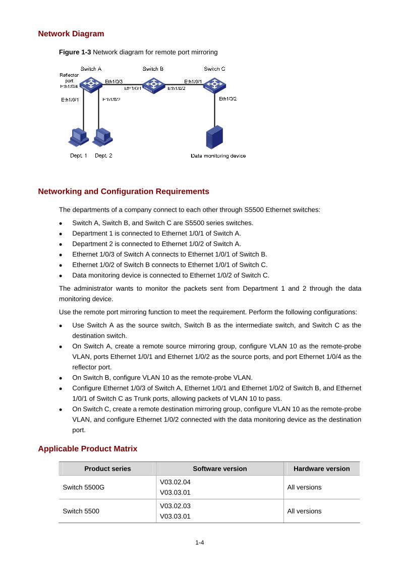
1-4
Network Diagram
Figure 1-3 Network diagram for remote port mirroring
Networking and Configuration Requirements
The departments of a company connect to each other through S5500 Ethernet switches:
Switch A, Switch B, and Switch C are S5500 series switches. Department 1 is connected to Ethernet 1/0/1 of Switch A. Department 2 is connected to Ethernet 1/0/2 of Switch A. Ethernet 1/0/3 of Switch A connects to Ethernet 1/0/1 of Switch B. Ethernet 1/0/2 of Switch B connects to Ethernet 1/0/1 of Switch C. Data monitoring device is connected to Ethernet 1/0/2 of Switch C.
The administrator wants to monitor the packets sent from Department 1 and 2 through the data monitoring device.
Use the remote port mirroring function to meet the requirement. Perform the following configurations:
Use Switch A as the source switch, Switch B as the intermediate switch, and Switch C as the destination switch.
On Switch A, create a remote source mirroring group, configure VLAN 10 as the remote-probe VLAN, ports Ethernet 1/0/1 and Ethernet 1/0/2 as the source ports, and port Ethernet 1/0/4 as the reflector port.
On Switch B, configure VLAN 10 as the remote-probe VLAN. Configure Ethernet 1/0/3 of Switch A, Ethernet 1/0/1 and Ethernet 1/0/2 of Switch B, and Ethernet
1/0/1 of Switch C as Trunk ports, allowing packets of VLAN 10 to pass. On Switch C, create a remote destination mirroring group, configure VLAN 10 as the remote-probe
VLAN, and configure Ethernet 1/0/2 connected with the data monitoring device as the destination port.
Applicable Product Matrix
Product series Software version Hardware version
Switch 5500G V03.02.04 V03.03.01
All versions
Switch 5500 V03.02.03 V03.03.01
All versions
1-5
Product series Software version Hardware version
Switch 4500 V03.02.00 V03.03.00
All versions
Switch 4200G V03.02.00 All versions
Configuration Procedure
1) Configure the source switch (Switch A)
# Create remote source mirroring group 1.
<Sysname> system-view
[Sysname] mirroring-group 1 remote-source
# Configure VLAN 10 as the remote-probe VLAN.
[Sysname] vlan 10
[Sysname-vlan10] remote-probe vlan enable
[Sysname-vlan10] quit
# Configure the source ports, reflector port, and remote-probe VLAN for the remote source mirroring group.
[Sysname] mirroring-group 1 mirroring-port Ethernet 1/0/1 Ethernet 1/0/2 inbound
[Sysname] mirroring-group 1 reflector-port Ethernet 1/0/4
[Sysname] mirroring-group 1 remote-probe vlan 10
# Configure Ethernet 1/0/3 as a Trunk port, allowing packets of VLAN 10 to pass.
[Sysname] interface Ethernet 1/0/3
[Sysname-Ethernet1/0/3] port link-type trunk
[Sysname-Ethernet1/0/3] port trunk permit vlan 10
2) Configure the intermediate switch (Switch B)
# Configure VLAN 10 as the remote-probe VLAN.
<Sysname> system-view
[Sysname] vlan 10
[Sysname-vlan10] remote-probe vlan enable
[Sysname-vlan10] quit
# Configure Ethernet 1/0/1 as a Trunk port, allowing packets of VLAN 10 to pass.
[Sysname] interface Ethernet 1/0/1
[Sysname-Ethernet1/0/1] port link-type trunk
[Sysname-Ethernet1/0/1] port trunk permit vlan 10
# Configure Ethernet 1/0/2 as a Trunk port, allowing packets of VLAN 10 to pass.
[Sysname] interface Ethernet 1/0/2
[Sysname-Ethernet1/0/2] port link-type trunk
[Sysname-Ethernet1/0/2] port trunk permit vlan 10
3) Configure the destination switch (Switch C)
# Create remote destination mirroring group 1.
<Sysname> system-view
[Sysname] mirroring-group 1 remote-destination
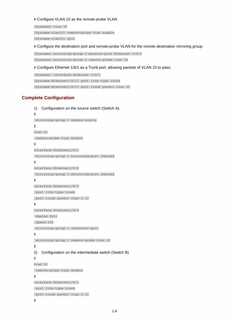
1-6
# Configure VLAN 10 as the remote-probe VLAN.
[Sysname] vlan 10
[Sysname-vlan10] remote-probe vlan enable
[Sysname-vlan10] quit
# Configure the destination port and remote-probe VLAN for the remote destination mirroring group.
[Sysname] mirroring-group 1 monitor-port Ethernet 1/0/2
[Sysname] mirroring-group 1 remote-probe vlan 10
# Configure Ethernet 1/0/1 as a Trunk port, allowing packets of VLAN 10 to pass.
[Sysname] interface Ethernet 1/0/1
[Sysname-Ethernet1/0/1] port link-type trunk
[Sysname-Ethernet1/0/1] port trunk permit vlan 10
Complete Configuration
1) Configuration on the source switch (Switch A) #
mirroring-group 1 remote-source
#
vlan 10
remote-probe vlan enable
#
interface Ethernet1/0/1
mirroring-group 1 mirroring-port inbound
#
interface Ethernet1/0/2
mirroring-group 1 mirroring-port inbound
#
interface Ethernet1/0/3
port link-type trunk
port trunk permit vlan 1 10
#
interface Ethernet1/0/4
duplex full
speed 100
mirroring-group 1 reflector-port
#
mirroring-group 1 remote-probe vlan 10
#
2) Configuration on the intermediate switch (Switch B) #
vlan 10
remote-probe vlan enable
#
interface Ethernet1/0/1
port link-type trunk
port trunk permit vlan 1 10
#
1-7
interface Ethernet1/0/2
port link-type trunk
port trunk permit vlan 1 10
#
3) Configuration on the destination switch (Switch C) #
mirroring-group 1 remote-destination
#
vlan 10
remote-probe vlan enable
#
interface Ethernet1/0/1
port link-type trunk
port trunk permit vlan 1 10
#
interface Ethernet1/0/2
port access vlan 10
mirroring-group 1 monitor-port
#
Precautions
Note the following when configuring the source switch:
All ports in a remote source mirroring group are on the same switch (the source switch). A remote source mirroring group can have only one reflector port.
The reflector port of a mirroring group cannot be a member port of another existing mirroring group, a fabric port (only the S5500/S5500G series Ethernet switches have this limitation), a member port of an aggregation group, or a port enabled with LACP or STP. It must be an Access port and cannot be configured with functions like VLAN-VPN, port loopback detection, packet filtering, QoS, port security, and so on.
You cannot modify the duplex mode, port rate, and MDI attribute of a reflector port. For mirroring to function properly, do not configure VLAN mapping or selective QinQ on a reflector
port. Only an existing static VLAN can be configured as the remote-probe VLAN. To remove a
remote-probe VLAN, you need to restore it to a normal VLAN first. A remote port mirroring group gets invalid if the corresponding remote-probe VLAN is removed.
Do not configure the default VLAN, management VLAN or dynamic VLAN as the remote-probe VLAN.
Configure all ports connecting the devices in the remote-probe VLAN as Trunk ports, and ensure the Layer 2 connectivity from the source switch to the destination switch over the remote-probe VLAN.
Do not configure a Layer 3 interface for the remote-probe VLAN, run other protocol packets, or carry other service packets on the remote-prove VLAN and do not use the remote-prove VLAN as the voice VLAN and protocol-based VLAN; otherwise, remote port mirroring may be affected.
Do not configure a port connecting the intermediate switch or destination switch as the mirroring source port. Otherwise, traffic disorder may occur in the network.
If the intermediate or destination switch is an S5500/S5500G, the bidirectional mirroring (the both keyword) function is not available.
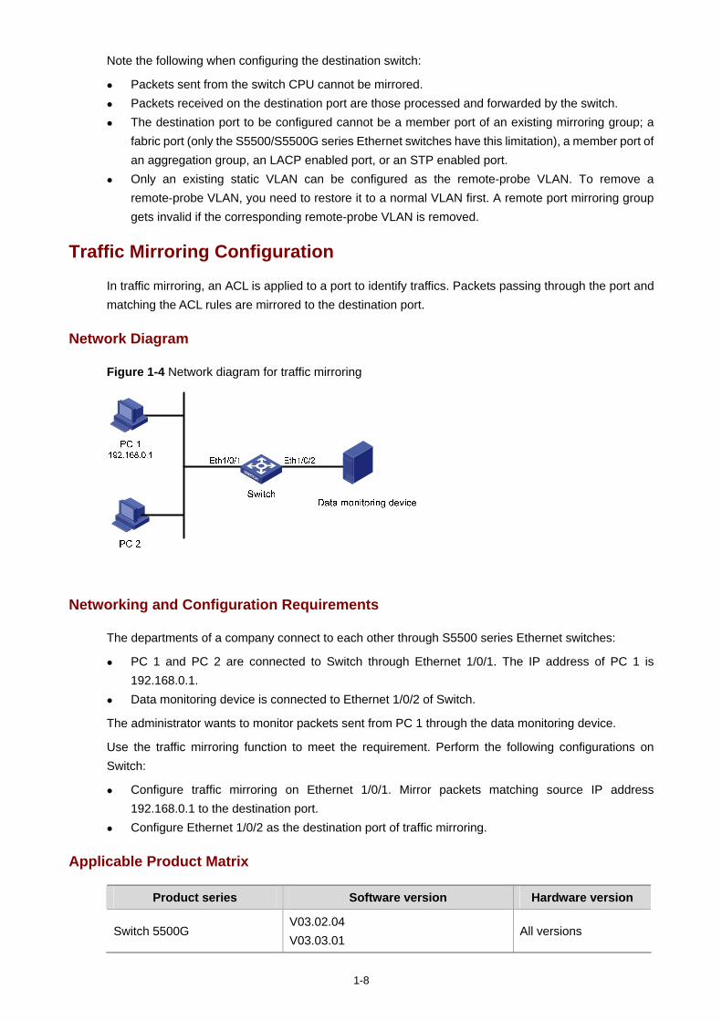
1-8
Note the following when configuring the destination switch:
Packets sent from the switch CPU cannot be mirrored. Packets received on the destination port are those processed and forwarded by the switch. The destination port to be configured cannot be a member port of an existing mirroring group; a
fabric port (only the S5500/S5500G series Ethernet switches have this limitation), a member port of an aggregation group, an LACP enabled port, or an STP enabled port.
Only an existing static VLAN can be configured as the remote-probe VLAN. To remove a remote-probe VLAN, you need to restore it to a normal VLAN first. A remote port mirroring group gets invalid if the corresponding remote-probe VLAN is removed.
Traffic Mirroring Configuration
In traffic mirroring, an ACL is applied to a port to identify traffics. Packets passing through the port and matching the ACL rules are mirrored to the destination port.
Network Diagram
Figure 1-4 Network diagram for traffic mirroring
Networking and Configuration Requirements
The departments of a company connect to each other through S5500 series Ethernet switches:
PC 1 and PC 2 are connected to Switch through Ethernet 1/0/1. The IP address of PC 1 is 192.168.0.1.
Data monitoring device is connected to Ethernet 1/0/2 of Switch.
The administrator wants to monitor packets sent from PC 1 through the data monitoring device.
Use the traffic mirroring function to meet the requirement. Perform the following configurations on Switch:
Configure traffic mirroring on Ethernet 1/0/1. Mirror packets matching source IP address 192.168.0.1 to the destination port.
Configure Ethernet 1/0/2 as the destination port of traffic mirroring.
Applicable Product Matrix
Product series Software version Hardware version
Switch 5500G V03.02.04 V03.03.01
All versions
1-9
Product series Software version Hardware version
Switch 5500 V03.02.03 V03.03.01
All versions
Switch 4200G V03.02.00 All versions
Configuration Procedure
# Configure a basic ACL 2000, matching the packets whose source IP address is 192.168.0.1.
<Sysname> system-view
[Sysname] acl number 2000
[Sysname-acl-basic-2000] rule permit source 192.168.0.1 0
[Sysname-acl-basic-2000] quit
# Configure traffic mirroring on Ethernet 1/0/1. Mirror packets matching source IP address 192.168.0.1 to the destination port.
[Sysname] interface Ethernet 1/0/1
[Sysname-Ethernet1/0/1] mirrored-to inbound ip-group 2000 monitor-interface
[Sysname-Ethernet1/0/1] quit
# Configure Ethernet 1/0/2 as the destination port of traffic mirroring.
[Sysname] interface Ethernet 1/0/2
[Sysname-Ethernet1/0/2] monitor-port
Complete Configuration
#
mirroring-group 1 local
#
acl number 2000
rule 0 permit source 192.168.0.1 0
#
interface Ethernet1/0/1
mirrored-to inbound ip-group 2000 rule 0 monitor-interface
#
interface Ethernet1/0/2
mirroring-group 1 monitor-port
#
Precautions
Note the following when configuring traffic mirroring:
The destination port to be configured cannot be a member port of an existing mirroring group, a fabric port (only the S5500/S5500G series Ethernet switches have this limitation), a member port of an aggregation group, an LACP enabled port, or an STP enabled port.
When you configure the destination port of traffic mirroring on an S5500 series Ethernet switch, if mirroring group 1 does not exist on the switch, the switch will automatically create local mirroring group 1 and add the destination port to the group; if mirroring group 1 already exists but is not a local mirroring group, your configuration of the destination port will fail.
i
Table of Contents
1 XRN Fabric Configuration Guide ·············································································································1-1 XRN Fabric Configuration ·······················································································································1-1
Network Diagram·····························································································································1-1 Networking and Configuration Requirements··················································································1-1 Applicable Product Matrix················································································································1-2 Fabric Cable Connection·················································································································1-2 Configuration Procedure··················································································································1-4 Complete Configuration···················································································································1-6 Precautions······································································································································1-7
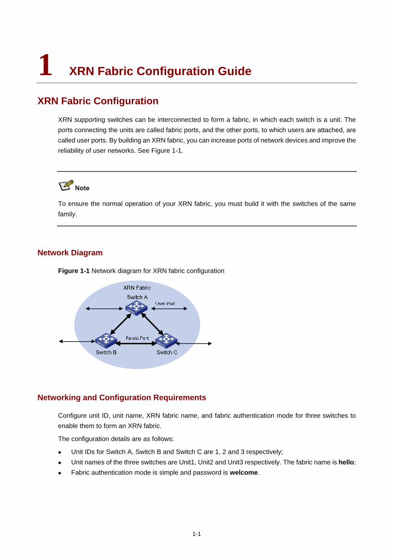
1-1
1 XRN Fabric Configuration Guide
XRN Fabric Configuration
XRN supporting switches can be interconnected to form a fabric, in which each switch is a unit. The ports connecting the units are called fabric ports, and the other ports, to which users are attached, are called user ports. By building an XRN fabric, you can increase ports of network devices and improve the reliability of user networks. See Figure 1-1.
To ensure the normal operation of your XRN fabric, you must build it with the switches of the same family.
Network Diagram
Figure 1-1 Network diagram for XRN fabric configuration
Networking and Configuration Requirements
Configure unit ID, unit name, XRN fabric name, and fabric authentication mode for three switches to enable them to form an XRN fabric.
The configuration details are as follows:
Unit IDs for Switch A, Switch B and Switch C are 1, 2 and 3 respectively; Unit names of the three switches are Unit1, Unit2 and Unit3 respectively. The fabric name is hello; Fabric authentication mode is simple and password is welcome.
1-2
The Switch 5500G series switches do not support the fabric authentication function.
Applicable Product Matrix
Product family Software version Hardware version
Switch 4500 V03.02.00 V03.03.00
All versions
Switch 5500 V03.02.03 V03.03.01
All versions
Switch 5500G V03.02.04 V03.03.01
All versions
Fabric Cable Connection
Before connecting switches to form a fabric, you are recommended to complete the configurations described in section Configuration Procedure on them.
Fabric cable connection for the Switch 4500 family and the Switch 5500 family
When connecting Switch 4500 units or Switch 5500 units to form an XRN fabric, follow these guidelines:
Connect the switches with their fabric ports. Each Switch 4500 or Switch 5500 unit has two fabric ports: left port and right port. Given a switch,
connect its left port to the right port of another switch, and its right port to the left port of a third one.
On the Switch 4500 or the Switch 5500, only four GigabitEthernet ports can be configured as fabric ports. The four ports fall into two groups according to their port numbers:
GigabitEthernet 1/1/1 and GigabitEthernet 1/1/2 form the first group. GigabitEthernet 1/1/3 and GigabitEthernet 1/1/4 form the second group.
Only one group of ports can be configured as fabric ports at a time. GigabitEthernet 1/1/1 and GigabitEthernet 1/1/3 are the left fabric ports of the first and the second group respectively, and GigabitEthernet 1/1/2 and GigabitEthernet 1/1/4 are the right fabric ports or the first and the second group respectively.
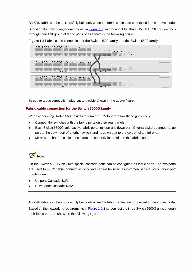
1-3
An XRN fabric can be successfully built only when the fabric cables are connected in the above mode.
Based on the networking requirements in Figure 1-1, interconnect the three S5500-EI 28 port switches through their first group of fabric ports of as shown in the following figure:
Figure 1-2 Fabric cable connection for the Switch 4500 family and the Switch 5500 family
ModeGreen=SpeedYellow=Duplex
RPS
PWR
Console Unit
1000Base-X
1Speed:Green=100Mbps,Yellow=10Mbps
2 3 4 5 6 7 8 9 10 11 12 13 14 15 16 17 18 19 20 21 22 23 24
25 26 27 28
Duplx:Green=Full Duplx,Yellow=Half Duplx H3C S3600 Series
10/100Base-TX
ModeGreen=SpeedYellow=Duplex
RPS
PWR
Console Unit
1000Base-X
1Speed:Green=100Mbps,Yellow=10Mbps
2 3 4 5 6 7 8 9 10 11 12 13 14 15 16 17 18 19 20 21 22 23 24
25 26 27 28
Duplx:Green=Full Duplx,Yellow=Half Duplx H3C S3600 Series
10/100Base-TX
ModeGreen=SpeedYellow=Duplex
RPS
PWR
Console Unit
1000Base-X
1Speed:Green=100Mbps,Yellow=10Mbps
2 3 4 5 6 7 8 9 10 11 12 13 14 15 16 17 18 19 20 21 22 23 24
25 26 27 28
Duplx:Green=Full Duplx,Yellow=Half Duplx H3C S3600 Series
10/100Base-TX
To set up a bus connection, plug out any cable shown in the above figure.
Fabric cable connection for the Switch 5500G family
When connecting Switch 5500G units to form an XRN fabric, follow these guidelines:
Connect the switches with the fabric ports on their rear panels. Each Switch 5500G unit has two fabric ports: up port and down port. Given a switch, connect its up
port to the down port of another switch, and its down port to the up port of a third one. Make sure that the cable connectors are securely inserted into the fabric ports.
On the Switch 5500G, only two special cascade ports can be configured as fabric ports. The two ports are used for XRN fabric connection only and cannot be used as common service ports. Their port numbers are:
Up port: Cascade 1/2/1 Down port: Cascade 1/2/2
An XRN fabric can be successfully built only when the fabric cables are connected in the above mode.
Based on the networking requirements in Figure 1-1, interconnect the three Switch 5500G units through their fabric ports as shown in the following figure:
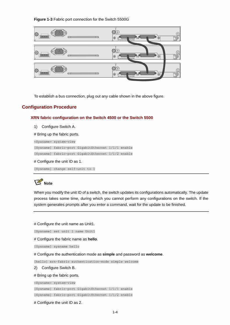
1-4
Figure 1-3 Fabric port connection for the Switch 5500G
To establish a bus connection, plug out any cable shown in the above figure.
Configuration Procedure
XRN fabric configuration on the Switch 4500 or the Switch 5500
1) Configure Switch A.
# Bring up the fabric ports.
<Sysname> system-view
[Sysname] fabric-port GigabitEthernet 1/1/1 enable
[Sysname] fabric-port GigabitEthernet 1/1/2 enable
# Configure the unit ID as 1.
[Sysname] change self-unit to 1
When you modify the unit ID of a switch, the switch updates its configurations automatically. The update process takes some time, during which you cannot perform any configurations on the switch. If the system generates prompts after you enter a command, wait for the update to be finished.
# Configure the unit name as Unit1.
[Sysname] set unit 1 name Unit1
# Configure the fabric name as hello.
[Sysname] sysname hello
# Configure the authentication mode as simple and password as welcome.
[hello] xrn-fabric authentication-mode simple welcome
2) Configure Switch B.
# Bring up the fabric ports.
<Sysname> system-view
[Sysname] fabric-port GigabitEthernet 1/1/1 enable
[Sysname] fabric-port GigabitEthernet 1/1/2 enable
# Configure the unit ID as 2.
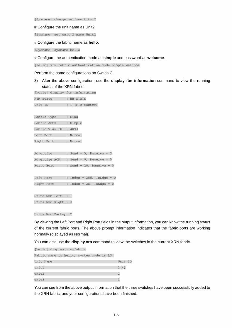
1-5
[Sysname] change self-unit to 2
# Configure the unit name as Unit2.
[Sysname] set unit 2 name Unit2
# Configure the fabric name as hello.
[Sysname] sysname hello
# Configure the authentication mode as simple and password as welcome.
[hello] xrn-fabric authentication-mode simple welcome
Perform the same configurations on Switch C.
3) After the above configuration, use the display ftm information command to view the running status of the XRN fabric.
[hello] display ftm information
FTM State : HB STATE
Unit ID : 1 (FTM-Master)
Fabric Type : Ring
Fabric Auth : Simple
Fabric Vlan ID : 4093
Left Port : Normal
Right Port : Normal
Advertise : Send = 5, Receive = 3
Advertise ACK : Send = 0, Receive = 5
Heart Beat : Send = 20, Receive = 0
Left Port : Index = 255, IsEdge = 0
Right Port : Index = 25, IsEdge = 0
Units Num Left : 1
Units Num Right : 3
Units Num Backup: 2
By viewing the Left Port and Right Port fields in the output information, you can know the running status of the current fabric ports. The above prompt information indicates that the fabric ports are working normally (displayed as Normal).
You can also use the display xrn command to view the switches in the current XRN fabric.
[hello] display xrn-fabric
Fabric name is hello, system mode is L3.
Unit Name Unit ID
unit1 1(*)
unit2 2
unit3 3
You can see from the above output information that the three switches have been successfully added to the XRN fabric, and your configurations have been finished.
1-6
XRN fabric configuration on the Switch 5500G
1) Configure Switch A
# Bring up the fabric ports.
<Sysname> system-view
[Sysname] fabric-port Cascade 1/2/1 enable
[Sysname] fabric-port Cascade 1/2/2 enable
# Configure the unit ID as 1.
[Sysname] change self-unit to 1
# Configure the unit name as Unit1.
[Sysname] set unit 1 name Unit1
# Configure the fabric name as hello.
[Sysname] sysname hello
2) Configure Switch B.
# Bring up the fabric ports.
<Sysname> system-view
[Sysname] fabric-port Cascade 1/2/1 enable
[Sysname] fabric-port Cascade 1/2/2 enable
# Configure the unit ID as 2.
[Sysname] change self-unit to 2
# Configure the unit name as Unit2.
[Sysname] set unit 2 name Unit2
# Configure the fabric name as hello.
[Sysname] sysname hello
The configurations and verification on Switch C are the same as those on the Switch A and Switch B. Therefore they are omitted here.
Complete Configuration
Complete configuration on the Switch 4500 or the Switch 5500
To avoid repetition, only the complete configuration of Switch A is listed below.
Configuration on Switch A. #
system-view
fabric-port GigabitEthernet 1/1/1 enable
fabric-port GigabitEthernet 1/1/2 enable
#
change unit-id 1 to 1
1-7
#
set unit 1 name Unit1
#
sysname hello
#
xrn-fabric authentication-mode simple welcome
Complete configuration on the Switch 5500G
To avoid repetition, only the complete configuration of Switch A is listed below.
Configurations on Switch A. #
system-view
fabric-port Cascade 1/2/1 enable
fabric-port Cascade 1/2/2 enable
#
change unit-id 1 to 1
#
set unit 1 name Unit1
#
sysname hello
#
The change unit-id and set unit name commands will not be saved in the configuration file, that is, when you use the display current-configuration or display saved-configuration command to view the content of the configuration file, the two commands are not displayed.
Precautions
When building an XRN fabric, follow these guidelines:
Make sure that the switches to be used are from the same family and using the same software version.
Check that the fabric cable connections of the switches are correct. Establishing an XRN system requires a high consistency of the configuration of each device.
Hence, before you enable a fabric port, do not perform any configuration for the port, and do not configure functions that may affect the performance of XRN (such as VLAN-VPN) for other ports or globally. Otherwise, you cannot enable the fabric port. For detailed restrictions, refer to the error information output by devices.
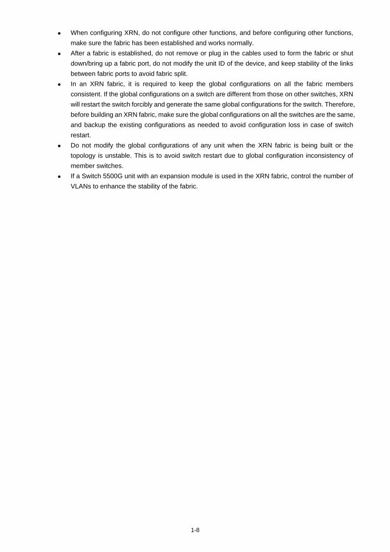
1-8
When configuring XRN, do not configure other functions, and before configuring other functions, make sure the fabric has been established and works normally.
After a fabric is established, do not remove or plug in the cables used to form the fabric or shut down/bring up a fabric port, do not modify the unit ID of the device, and keep stability of the links between fabric ports to avoid fabric split.
In an XRN fabric, it is required to keep the global configurations on all the fabric members consistent. If the global configurations on a switch are different from those on other switches, XRN will restart the switch forcibly and generate the same global configurations for the switch. Therefore, before building an XRN fabric, make sure the global configurations on all the switches are the same, and backup the existing configurations as needed to avoid configuration loss in case of switch restart.
Do not modify the global configurations of any unit when the XRN fabric is being built or the topology is unstable. This is to avoid switch restart due to global configuration inconsistency of member switches.
If a Switch 5500G unit with an expansion module is used in the XRN fabric, control the number of VLANs to enhance the stability of the fabric.
i
Table of Contents
1 Cluster Configuration Guide ····················································································································1-1 Cluster Configuration ······························································································································1-1
Network Diagram·····························································································································1-1 Networking and Configuration Requirements··················································································1-1 Applicable Product Matrix················································································································1-2 Configuration Procedure··················································································································1-2 Complete Configuration···················································································································1-4 Precautions······································································································································1-5
Network Management Interface Configuration ·······················································································1-5 Network Diagram·····························································································································1-5 Networking and Configuration Requirements··················································································1-5 Applicable Product Matrix················································································································1-6 Configuration Procedure··················································································································1-6 Complete Configuration···················································································································1-7 Precautions······································································································································1-7
Cluster Configuration in Real Networking·······························································································1-8 Network Diagram·····························································································································1-8 Networking and Configuration Requirements··················································································1-8 Applicable Product Matrix················································································································1-9 Configuration Procedure··················································································································1-9 Complete Configuration·················································································································1-11 Precautions····································································································································1-12
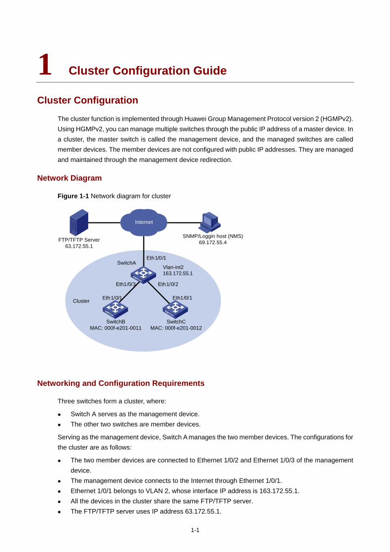
1-1
1 Cluster Configuration Guide
Cluster Configuration
The cluster function is implemented through Huawei Group Management Protocol version 2 (HGMPv2). Using HGMPv2, you can manage multiple switches through the public IP address of a master device. In a cluster, the master switch is called the management device, and the managed switches are called member devices. The member devices are not configured with public IP addresses. They are managed and maintained through the management device redirection.
Network Diagram
Figure 1-1 Network diagram for cluster
Internet
Eth 1/0/1
Eth 1/0/3 Eth 1/0/2
Eth 1/0/1 Eth 1/0/1
163.172.55.1Vlan-int2
Cluster
SwitchA
SwitchBMAC: 000f-e201-0011
SwitchCMAC: 000f-e201-0012
SNMP/Loggin host (NMS)69.172.55.4FTP/TFTP Server
63.172.55.1
Networking and Configuration Requirements
Three switches form a cluster, where:
Switch A serves as the management device. The other two switches are member devices.
Serving as the management device, Switch A manages the two member devices. The configurations for the cluster are as follows:
The two member devices are connected to Ethernet 1/0/2 and Ethernet 1/0/3 of the management device.
The management device connects to the Internet through Ethernet 1/0/1. Ethernet 1/0/1 belongs to VLAN 2, whose interface IP address is 163.172.55.1. All the devices in the cluster share the same FTP/TFTP server. The FTP/TFTP server uses IP address 63.172.55.1.
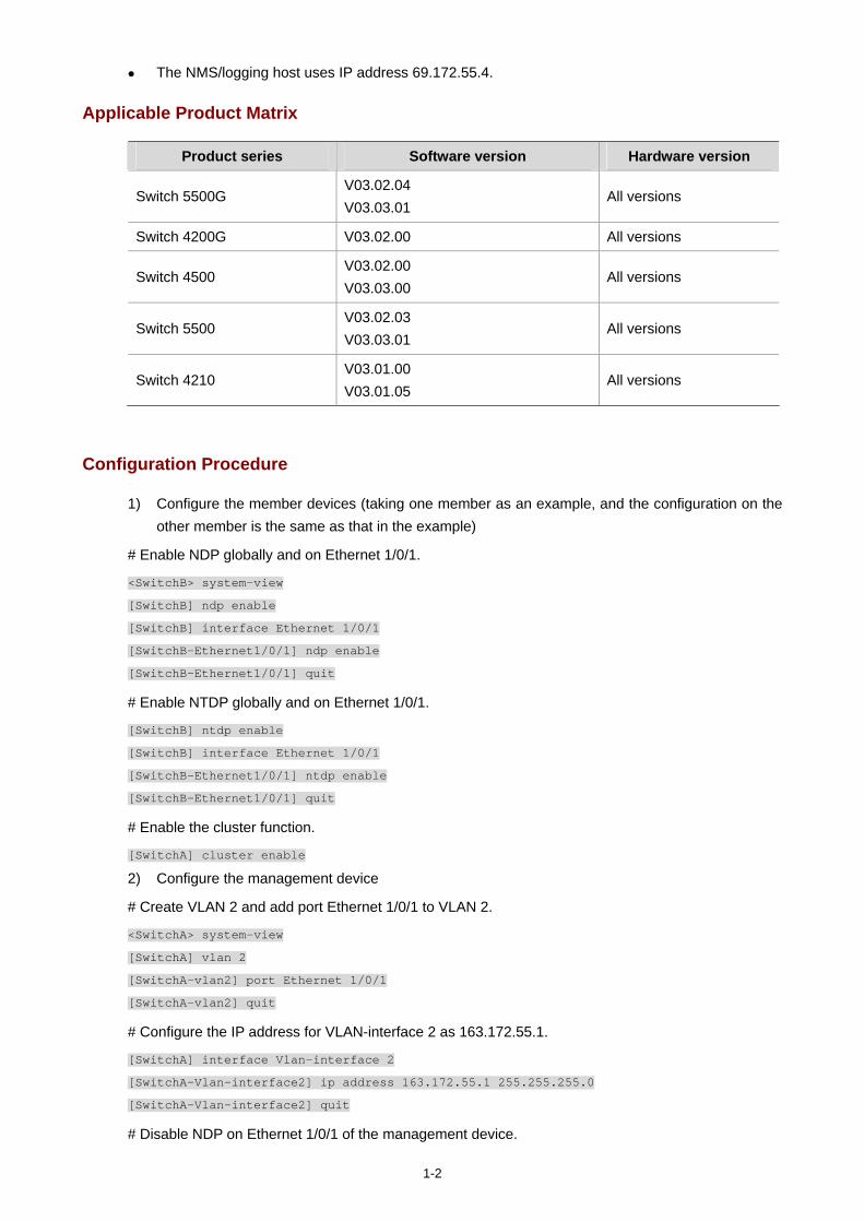
1-2
The NMS/logging host uses IP address 69.172.55.4.
Applicable Product Matrix
Product series Software version Hardware version
Switch 5500G V03.02.04 V03.03.01
All versions
Switch 4200G V03.02.00 All versions
Switch 4500 V03.02.00 V03.03.00
All versions
Switch 5500 V03.02.03 V03.03.01
All versions
Switch 4210 V03.01.00 V03.01.05
All versions
Configuration Procedure
1) Configure the member devices (taking one member as an example, and the configuration on the other member is the same as that in the example)
# Enable NDP globally and on Ethernet 1/0/1.
<SwitchB> system-view
[SwitchB] ndp enable
[SwitchB] interface Ethernet 1/0/1
[SwitchB-Ethernet1/0/1] ndp enable
[SwitchB-Ethernet1/0/1] quit
# Enable NTDP globally and on Ethernet 1/0/1.
[SwitchB] ntdp enable
[SwitchB] interface Ethernet 1/0/1
[SwitchB-Ethernet1/0/1] ntdp enable
[SwitchB-Ethernet1/0/1] quit
# Enable the cluster function.
[SwitchA] cluster enable
2) Configure the management device
# Create VLAN 2 and add port Ethernet 1/0/1 to VLAN 2.
<SwitchA> system-view
[SwitchA] vlan 2
[SwitchA-vlan2] port Ethernet 1/0/1
[SwitchA-vlan2] quit
# Configure the IP address for VLAN-interface 2 as 163.172.55.1.
[SwitchA] interface Vlan-interface 2
[SwitchA-Vlan-interface2] ip address 163.172.55.1 255.255.255.0
[SwitchA-Vlan-interface2] quit
# Disable NDP on Ethernet 1/0/1 of the management device.

1-3
[SwitchA] ndp enable
[SwitchA] undo ndp enable intferface Ethernet 1/0/1
[SwitchA] interface Ethernet 1/0/1
[SwitchA-Ethernet1/0/1] undo ntdp enable
[SwitchA-Ethernet1/0/1] quit
# Enable NDP on Ethernet 1/0/2 and Ethernet 1/0/3.
[SwitchA] interface Ethernet 1/0/2
[SwitchA-Ethernet1/0/2] ndp enable
[SwitchA-Ethernet1/0/2] quit
[SwitchA] interface Ethernet 1/0/3
[SwitchA-Ethernet1/0/3] ndp enable
[SwitchA-Ethernet1/0/3] quit
# Set the holdtime of NDP information to 200 seconds.
[SwitchA] ndp timer aging 200
# Set the interval between sending NDP packets to 70 seconds.
[SwitchA] ndp timer hello 70
# Enable NTDP globally and on Ethernet 1/0/2 and Ethernet 1/0/3.
[SwitchA] ntdp enable
[SwitchA] interface Ethernet 1/0/2
[SwitchA-Ethernet1/0/2] ntdp enable
[SwitchA-Ethernet1/0/2] quit
[SwitchA] interface Ethernet 1/0/3
[SwitchA-Ethernet1/0/3] ntdp enable
[SwitchA-Ethernet1/0/3] quit
# Set the topology collection range to two hops.
[SwitchA] ntdp hop 2
# Set the delay for a member device to forward topology collection request to 150 ms.
[SwitchA] ntdp timer hop-delay 150
# Set the delay for a port of a member device to forward topology collection request to 15 ms.
[SwitchA] ntdp timer port-delay 15
# Set the topology collection interval to three minutes.
[SwitchA] ntdp timer 3
# Enable the cluster function.
[SwitchA] cluster enable
# Enter cluster view.
[SwitchA] cluster
[SwitchA-cluster]
# Configure a private IP address pool for a cluster. The IP address pool contains six IP addresses, starting from 172.16.0.1.
[SwitchA-cluster] ip-pool 172.16.0.1 255.255.255.248
# Name and build a cluster.
[SwitchA-cluster] build aaa
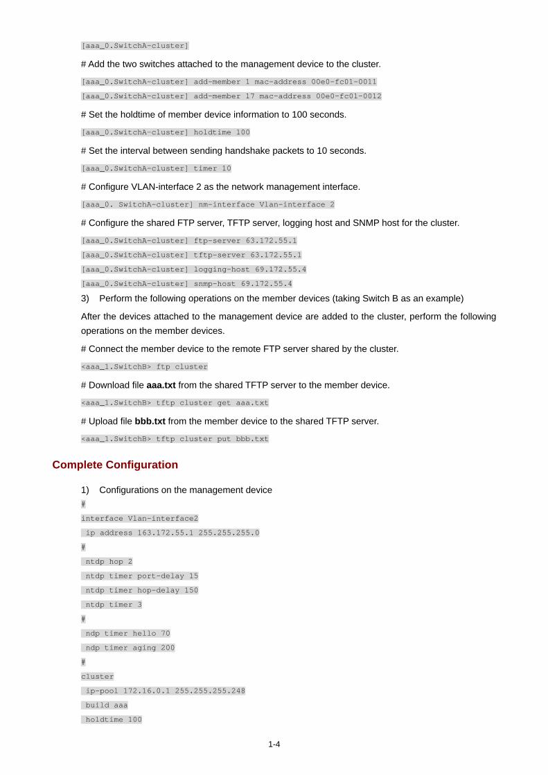
1-4
[aaa_0.SwitchA-cluster]
# Add the two switches attached to the management device to the cluster.
[aaa_0.SwitchA-cluster] add-member 1 mac-address 00e0-fc01-0011
[aaa_0.SwitchA-cluster] add-member 17 mac-address 00e0-fc01-0012
# Set the holdtime of member device information to 100 seconds.
[aaa_0.SwitchA-cluster] holdtime 100
# Set the interval between sending handshake packets to 10 seconds.
[aaa_0.SwitchA-cluster] timer 10
# Configure VLAN-interface 2 as the network management interface.
[aaa_0. SwitchA-cluster] nm-interface Vlan-interface 2
# Configure the shared FTP server, TFTP server, logging host and SNMP host for the cluster.
[aaa_0.SwitchA-cluster] ftp-server 63.172.55.1
[aaa_0.SwitchA-cluster] tftp-server 63.172.55.1
[aaa_0.SwitchA-cluster] logging-host 69.172.55.4
[aaa_0.SwitchA-cluster] snmp-host 69.172.55.4
3) Perform the following operations on the member devices (taking Switch B as an example)
After the devices attached to the management device are added to the cluster, perform the following operations on the member devices.
# Connect the member device to the remote FTP server shared by the cluster.
<aaa_1.SwitchB> ftp cluster
# Download file aaa.txt from the shared TFTP server to the member device.
<aaa_1.SwitchB> tftp cluster get aaa.txt
# Upload file bbb.txt from the member device to the shared TFTP server.
<aaa_1.SwitchB> tftp cluster put bbb.txt
Complete Configuration
1) Configurations on the management device #
interface Vlan-interface2
ip address 163.172.55.1 255.255.255.0
#
ntdp hop 2
ntdp timer port-delay 15
ntdp timer hop-delay 150
ntdp timer 3
#
ndp timer hello 70
ndp timer aging 200
#
cluster
ip-pool 172.16.0.1 255.255.255.248
build aaa
holdtime 100
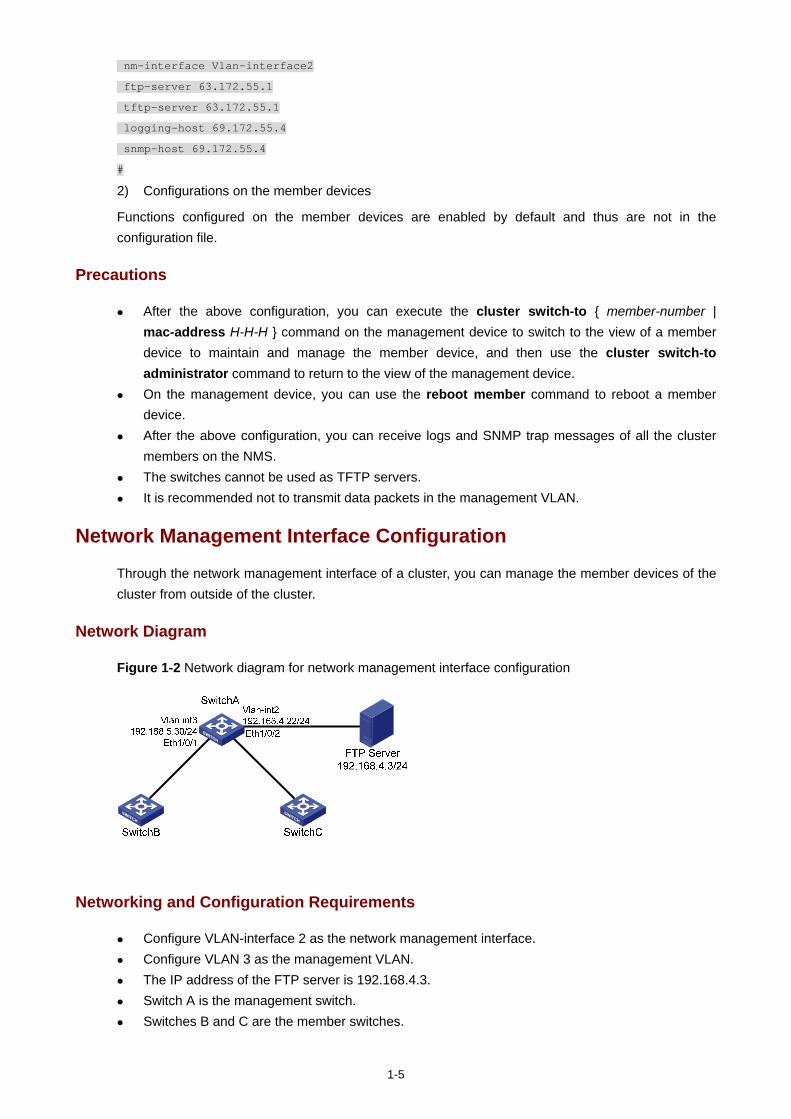
1-5
nm-interface Vlan-interface2
ftp-server 63.172.55.1
tftp-server 63.172.55.1
logging-host 69.172.55.4
snmp-host 69.172.55.4
#
2) Configurations on the member devices
Functions configured on the member devices are enabled by default and thus are not in the configuration file.
Precautions
After the above configuration, you can execute the cluster switch-to { member-number | mac-address H-H-H } command on the management device to switch to the view of a member device to maintain and manage the member device, and then use the cluster switch-to administrator command to return to the view of the management device.
On the management device, you can use the reboot member command to reboot a member device.
After the above configuration, you can receive logs and SNMP trap messages of all the cluster members on the NMS.
The switches cannot be used as TFTP servers. It is recommended not to transmit data packets in the management VLAN.
Network Management Interface Configuration
Through the network management interface of a cluster, you can manage the member devices of the cluster from outside of the cluster.
Network Diagram
Figure 1-2 Network diagram for network management interface configuration
Networking and Configuration Requirements
Configure VLAN-interface 2 as the network management interface. Configure VLAN 3 as the management VLAN. The IP address of the FTP server is 192.168.4.3. Switch A is the management switch. Switches B and C are the member switches.
1-6
Table 1-1 Connection information of the management switch
VLAN IP address Connection port
VLAN 3, connecting Switch B or Switch C) 192.168.5.30/24 Ethernet 1/0/1
VLAN 2, connecting the FTP Sever) 192.168.4.22/24 Ethernet 1/0/2
Applicable Product Matrix
Product series Software version Hardware version
Switch 5500G V03.02.04 V03.03.01
All versions
Switch 4500 V03.02.00 V03.03.00
All versions
Switch 5500 V03.02.03 V03.03.01
Configuration Procedure
Perform the following configurations on Switch A.
# Enter system view, create VLAN 3 and add Ethernet 1/0/1 to VLAN 3.
<SwitchA> system-view
[SwitchA] vlan 3
[SwitchA-vlan3] port Ethernet 1/0/1
[SwitchA-vlan3] quit
# Configure VLAN 3 as the management VLAN.
[SwitchA] management-vlan 3
# Configure the IP address of VLAN-interface 3 as 192.168.5.30.
[SwitchA] interface Vlan-interface 3
[SwitchA-Vlan-interface3] ip address 192.168.5.30 255.255.255.0
[SwitchA-Vlan-interface3] quit
# Add Ethernet 1/0/2 to VLAN 2.
[SwitchA] vlan 2
[SwitchA-vlan2] port Ethernet 1/0/2
[SwitchA-vlan2] quit
# Configure the IP address of VLAN-interface 2 as 192.168.4.22.
[SwitchA] interface Vlan-interface 2
[SwitchA-Vlan-interface2] ip address 192.168.4.22 255.255.255.0
[SwitchA-Vlan-interface2] quit
# Enable the cluster function.
[SwitchA] cluster enable
# Enter cluster view.

1-7
[SwitchA] cluster
[SwitchA -cluster]
# Configure a private IP address pool for a cluster. The IP address pool contains 30 IP addresses, starting from 192.168.5.1.
[SwitchA-cluster] ip-pool 192.168.5.1 255.255.255.224
# Name and build a cluster.
[SwitchA-cluster] build aaa
[aaa_0.SwitchA-cluster]
# Configure VLAN-interface 2 as the network management interface.
[aaa_0.SwitchA] cluster
[aaa_0.SwitchA-cluster] nm-interface Vlan-interface 2
Complete Configuration
#
vlan 2
#
vlan 3
#
interface Vlan-interface2
ip address 192.168.4.22 255.255.255.0
#
interface Vlan-interface3
ip address 192.168.5.30 255.255.255.0
#
management-vlan 3
#
interface Ethernet1/0/1
port access vlan 3
#
interface Ethernet1/0/2
port access vlan 2
#
cluster
ip-pool 192.168.5.1 255.255.255.224
build aaa
nm-interface Vlan-interface2
#
Precautions
The default network management interface is the management VLAN interface. There can be only one network management interface. A new configuration will overwrite the
previous one. The network management interface can be configured on the management switch only.
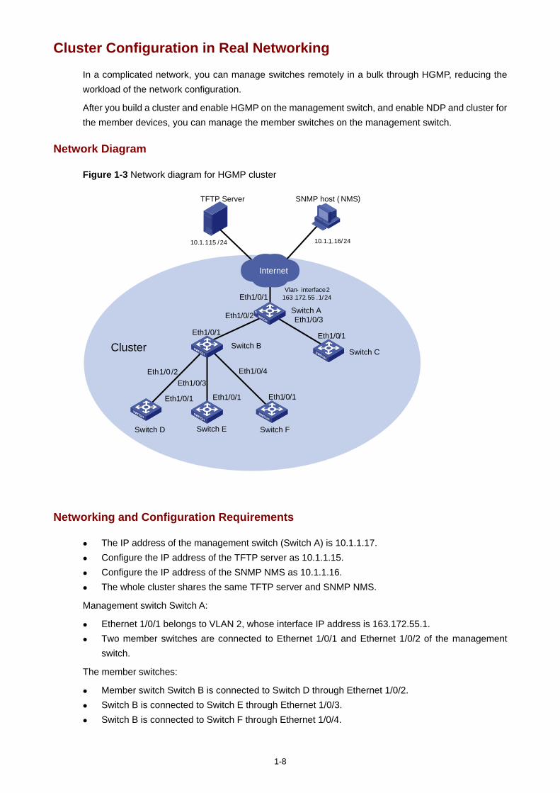
1-8
Cluster Configuration in Real Networking
In a complicated network, you can manage switches remotely in a bulk through HGMP, reducing the workload of the network configuration.
After you build a cluster and enable HGMP on the management switch, and enable NDP and cluster for the member devices, you can manage the member switches on the management switch.
Network Diagram
Figure 1-3 Network diagram for HGMP cluster
Switch D
Switch A
Switch B
Switch E Switch F
10.1.1.15 /24
SNMP host ( NMS)
10.1. 16/24
Eth 1/0 /2Eth 1/0/3
Eth 1/0/4
Eth 1/0/2 Eth 1/0/3Eth 1/0/1
TFTP Server
Eth 1/0/1Eth 1/0/1Eth 1/0/1
Vlan- interface 2163 .172. 55 .1/24
Switch C
Eth 1/0/1
Internet
Cluster
Eth 1/0/1
1.
Networking and Configuration Requirements
The IP address of the management switch (Switch A) is 10.1.1.17. Configure the IP address of the TFTP server as 10.1.1.15. Configure the IP address of the SNMP NMS as 10.1.1.16. The whole cluster shares the same TFTP server and SNMP NMS.
Management switch Switch A:
Ethernet 1/0/1 belongs to VLAN 2, whose interface IP address is 163.172.55.1. Two member switches are connected to Ethernet 1/0/1 and Ethernet 1/0/2 of the management
switch.
The member switches:
Member switch Switch B is connected to Switch D through Ethernet 1/0/2. Switch B is connected to Switch E through Ethernet 1/0/3. Switch B is connected to Switch F through Ethernet 1/0/4.
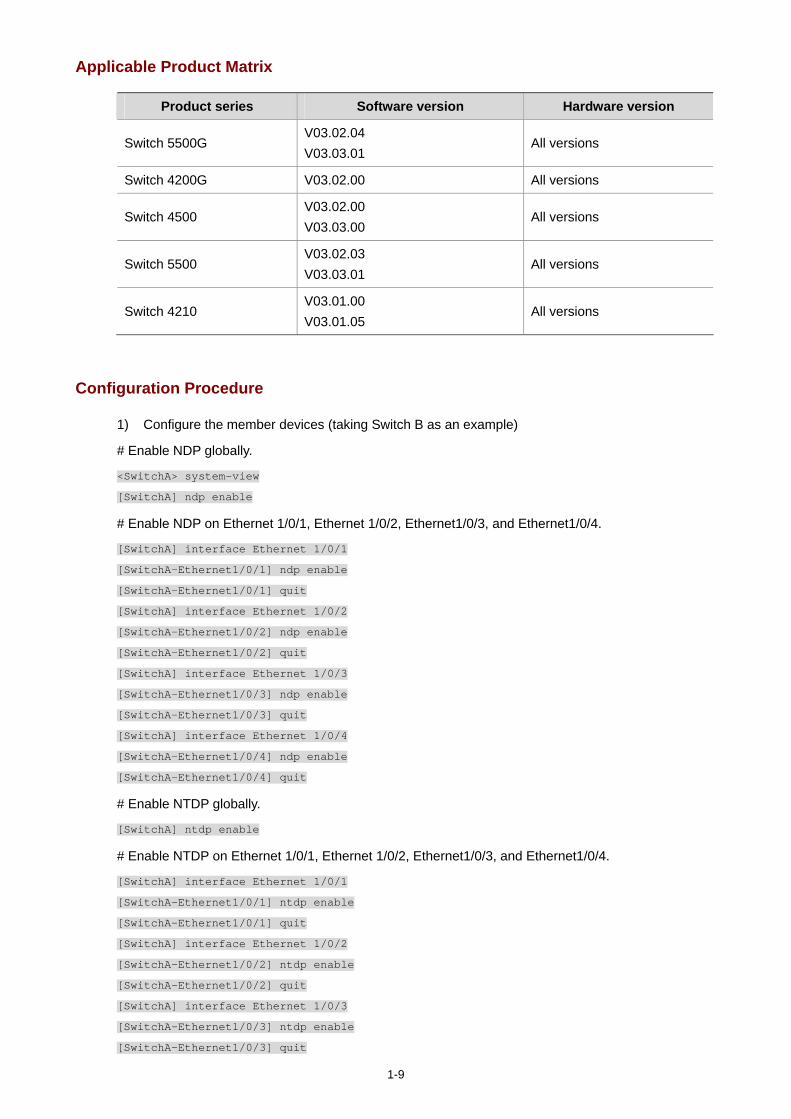
1-9
Applicable Product Matrix
Product series Software version Hardware version
Switch 5500G V03.02.04 V03.03.01
All versions
Switch 4200G V03.02.00 All versions
Switch 4500 V03.02.00 V03.03.00
All versions
Switch 5500 V03.02.03 V03.03.01
All versions
Switch 4210 V03.01.00 V03.01.05
All versions
Configuration Procedure
1) Configure the member devices (taking Switch B as an example)
# Enable NDP globally.
<SwitchA> system-view
[SwitchA] ndp enable
# Enable NDP on Ethernet 1/0/1, Ethernet 1/0/2, Ethernet1/0/3, and Ethernet1/0/4.
[SwitchA] interface Ethernet 1/0/1
[SwitchA-Ethernet1/0/1] ndp enable
[SwitchA-Ethernet1/0/1] quit
[SwitchA] interface Ethernet 1/0/2
[SwitchA-Ethernet1/0/2] ndp enable
[SwitchA-Ethernet1/0/2] quit
[SwitchA] interface Ethernet 1/0/3
[SwitchA-Ethernet1/0/3] ndp enable
[SwitchA-Ethernet1/0/3] quit
[SwitchA] interface Ethernet 1/0/4
[SwitchA-Ethernet1/0/4] ndp enable
[SwitchA-Ethernet1/0/4] quit
# Enable NTDP globally.
[SwitchA] ntdp enable
# Enable NTDP on Ethernet 1/0/1, Ethernet 1/0/2, Ethernet1/0/3, and Ethernet1/0/4.
[SwitchA] interface Ethernet 1/0/1
[SwitchA-Ethernet1/0/1] ntdp enable
[SwitchA-Ethernet1/0/1] quit
[SwitchA] interface Ethernet 1/0/2
[SwitchA-Ethernet1/0/2] ntdp enable
[SwitchA-Ethernet1/0/2] quit
[SwitchA] interface Ethernet 1/0/3
[SwitchA-Ethernet1/0/3] ntdp enable
[SwitchA-Ethernet1/0/3] quit
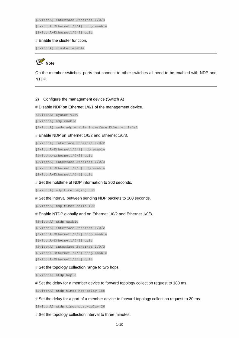
1-10
[SwitchA] interface Ethernet 1/0/4
[SwitchA-Ethernet1/0/4] ntdp enable
[SwitchA-Ethernet1/0/4] quit
# Enable the cluster function.
[SwitchA] cluster enable
On the member switches, ports that connect to other switches all need to be enabled with NDP and NTDP.
2) Configure the management device (Switch A)
# Disable NDP on Ethernet 1/0/1 of the management device.
<SwitchA> system-view
[SwitchA] ndp enable
[SwitchA] undo ndp enable interface Ethernet 1/0/1
# Enable NDP on Ethernet 1/0/2 and Ethernet 1/0/3.
[SwitchA] interface Ethernet 1/0/2
[SwitchA-Ethernet1/0/2] ndp enable
[SwitchA-Ethernet1/0/2] quit
[SwitchA] interface Ethernet 1/0/3
[SwitchA-Ethernet1/0/3] ndp enable
[SwitchA-Ethernet1/0/3] quit
# Set the holdtime of NDP information to 300 seconds.
[SwitchA] ndp timer aging 300
# Set the interval between sending NDP packets to 100 seconds.
[SwitchA] ndp timer hello 100
# Enable NTDP globally and on Ethernet 1/0/2 and Ethernet 1/0/3.
[SwitchA] ntdp enable
[SwitchA] interface Ethernet 1/0/2
[SwitchA-Ethernet1/0/2] ntdp enable
[SwitchA-Ethernet1/0/2] quit
[SwitchA] interface Ethernet 1/0/3
[SwitchA-Ethernet1/0/3] ntdp enable
[SwitchA-Ethernet1/0/3] quit
# Set the topology collection range to two hops.
[SwitchA] ntdp hop 2
# Set the delay for a member device to forward topology collection request to 180 ms.
[SwitchA] ntdp timer hop-delay 180
# Set the delay for a port of a member device to forward topology collection request to 20 ms.
[SwitchA] ntdp timer port-delay 20
# Set the topology collection interval to three minutes.
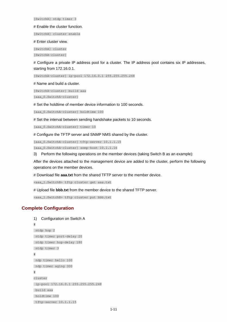
1-11
[SwitchA] ntdp timer 3
# Enable the cluster function.
[SwitchA] cluster enable
# Enter cluster view.
[SwitchA] cluster
[SwitchA-cluster]
# Configure a private IP address pool for a cluster. The IP address pool contains six IP addresses, starting from 172.16.0.1.
[SwitchA-cluster] ip-pool 172.16.0.1 255.255.255.248
# Name and build a cluster.
[SwitchA-cluster] build aaa
[aaa_0.SwitchA-cluster]
# Set the holdtime of member device information to 100 seconds.
[aaa_0.SwitchA-cluster] holdtime 100
# Set the interval between sending handshake packets to 10 seconds.
[aaa_0.SwitchA-cluster] timer 10
# Configure the TFTP server and SNMP NMS shared by the cluster.
[aaa_0.SwitchA-cluster] tftp-server 10.1.1.15
[aaa_0.SwitchA-cluster] snmp-host 10.1.1.16
3) Perform the following operations on the member devices (taking Switch B as an example):
After the devices attached to the management device are added to the cluster, perform the following operations on the member devices.
# Download file aaa.txt from the shared TFTP server to the member device.
<aaa_1.SwitchB> tftp cluster get aaa.txt
# Upload file bbb.txt from the member device to the shared TFTP server.
<aaa_1.SwitchB> tftp cluster put bbb.txt
Complete Configuration
1) Configuration on Switch A #
ntdp hop 2
ntdp timer port-delay 20
ntdp timer hop-delay 180
ntdp timer 3
#
ndp timer hello 100
ndp timer aging 300
#
cluster
ip-pool 172.16.0.1 255.255.255.248
build aaa
holdtime 100
tftp-server 10.1.1.15

1-12
snmp-host 10.1.1.16
2) Configurations on the member devices
Functions configured on the member devices are enabled by default and thus are not in the configuration file.
Precautions
None
i
Table of Contents
1 PoE/PoE Profile Configuration Guide······································································································1-1 PoE Configuration ···································································································································1-1
Network Diagram·····························································································································1-1 Networking and Configuration Requirements··················································································1-1 Applicable Product Matrix················································································································1-1 Configuration Procedure··················································································································1-2 Complete Configuration···················································································································1-3 Precautions······································································································································1-3
PoE Profile Configuration························································································································1-3 Network Diagram·····························································································································1-4 Networking and Configuration Requirements··················································································1-4 Applicable Product Matrix················································································································1-5 Configuration Procedure··················································································································1-5 Complete Configuration···················································································································1-5 Precautions······································································································································1-6
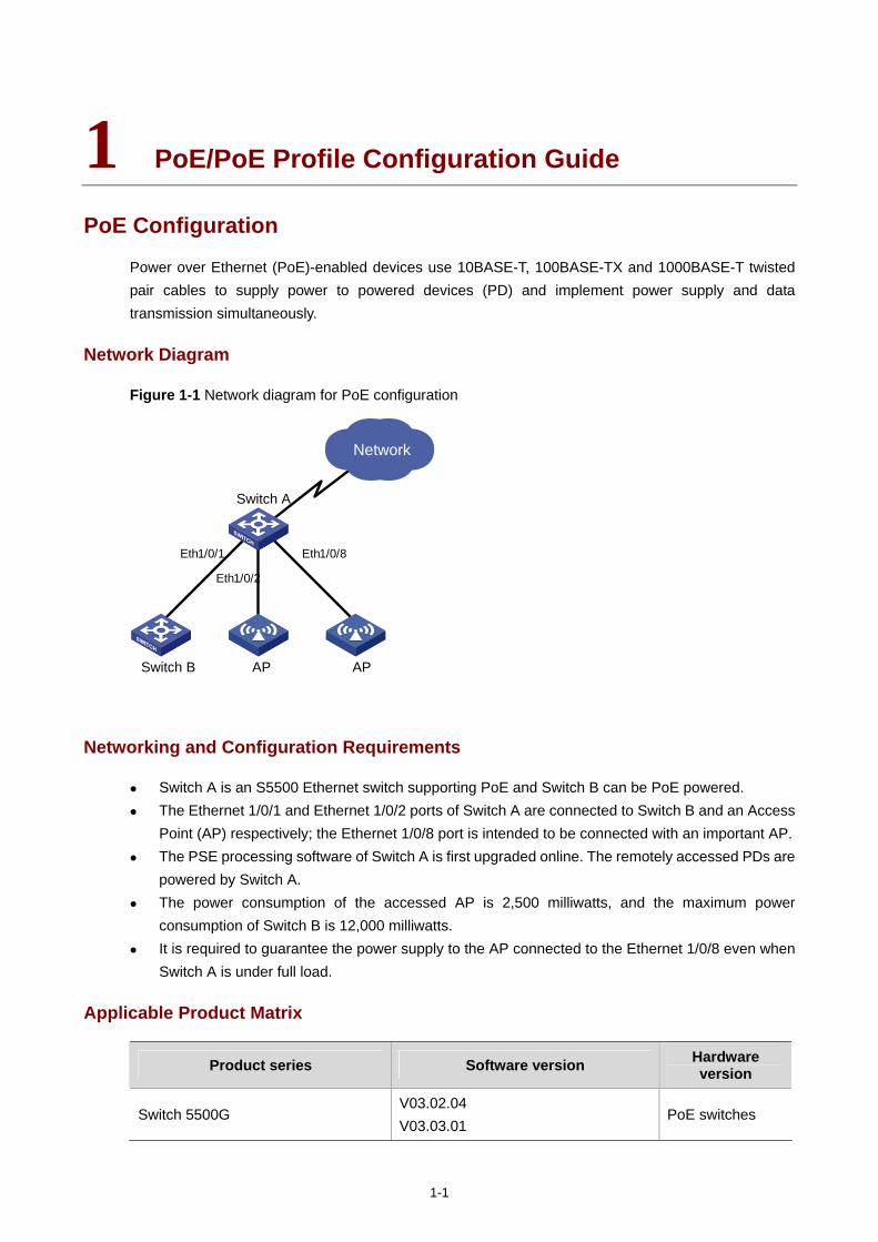
1-1
1 PoE/PoE Profile Configuration Guide
PoE Configuration
Power over Ethernet (PoE)-enabled devices use 10BASE-T, 100BASE-TX and 1000BASE-T twisted pair cables to supply power to powered devices (PD) and implement power supply and data transmission simultaneously.
Network Diagram
Figure 1-1 Network diagram for PoE configuration
Switch A
Network
Eth1/0/2
Eth1/0/1 Eth1/0/8
Switch B AP AP
Networking and Configuration Requirements
Switch A is an S5500 Ethernet switch supporting PoE and Switch B can be PoE powered. The Ethernet 1/0/1 and Ethernet 1/0/2 ports of Switch A are connected to Switch B and an Access
Point (AP) respectively; the Ethernet 1/0/8 port is intended to be connected with an important AP. The PSE processing software of Switch A is first upgraded online. The remotely accessed PDs are
powered by Switch A. The power consumption of the accessed AP is 2,500 milliwatts, and the maximum power
consumption of Switch B is 12,000 milliwatts. It is required to guarantee the power supply to the AP connected to the Ethernet 1/0/8 even when
Switch A is under full load.
Applicable Product Matrix
Product series Software version Hardware version
Switch 5500G V03.02.04 V03.03.01
PoE switches
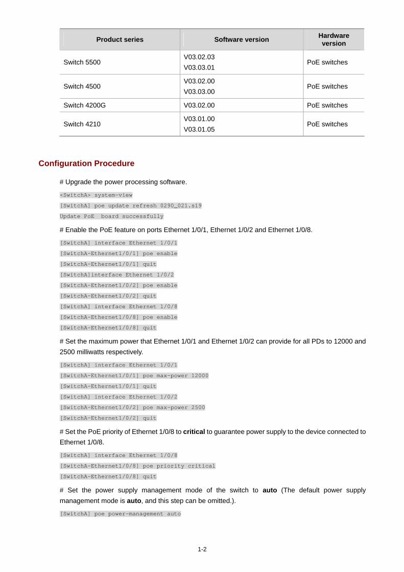
1-2
Product series Software version Hardware version
Switch 5500 V03.02.03 V03.03.01
PoE switches
Switch 4500 V03.02.00 V03.03.00
PoE switches
Switch 4200G V03.02.00 PoE switches
Switch 4210 V03.01.00 V03.01.05
PoE switches
Configuration Procedure
# Upgrade the power processing software.
<SwitchA> system-view
[SwitchA] poe update refresh 0290_021.s19
Update PoE board successfully
# Enable the PoE feature on ports Ethernet 1/0/1, Ethernet 1/0/2 and Ethernet 1/0/8.
[SwitchA] interface Ethernet 1/0/1
[SwitchA-Ethernet1/0/1] poe enable
[SwitchA-Ethernet1/0/1] quit
[SwitchA]interface Ethernet 1/0/2
[SwitchA-Ethernet1/0/2] poe enable
[SwitchA-Ethernet1/0/2] quit
[SwitchA] interface Ethernet 1/0/8
[SwitchA-Ethernet1/0/8] poe enable
[SwitchA-Ethernet1/0/8] quit
# Set the maximum power that Ethernet 1/0/1 and Ethernet 1/0/2 can provide for all PDs to 12000 and 2500 milliwatts respectively.
[SwitchA] interface Ethernet 1/0/1
[SwitchA-Ethernet1/0/1] poe max-power 12000
[SwitchA-Ethernet1/0/1] quit
[SwitchA] interface Ethernet 1/0/2
[SwitchA-Ethernet1/0/2] poe max-power 2500
[SwitchA-Ethernet1/0/2] quit
# Set the PoE priority of Ethernet 1/0/8 to critical to guarantee power supply to the device connected to Ethernet 1/0/8.
[SwitchA] interface Ethernet 1/0/8
[SwitchA-Ethernet1/0/8] poe priority critical
[SwitchA-Ethernet1/0/8] quit
# Set the power supply management mode of the switch to auto (The default power supply management mode is auto, and this step can be omitted.).
[SwitchA] poe power-management auto
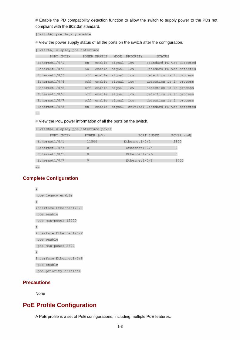
1-3
# Enable the PD compatibility detection function to allow the switch to supply power to the PDs not compliant with the 802.3af standard.
[SwitchA] poe legacy enable
# View the power supply status of all the ports on the switch after the configuration.
[SwitchA] display poe interface
PORT INDEX POWER ENABLE MODE PRIORITY STATUS
Ethernet1/0/1 on enable signal low Standard PD was detected
Ethernet1/0/2 on enable signal low Standard PD was detected
Ethernet1/0/3 off enable signal low detection is in process
Ethernet1/0/4 off enable signal low detection is in process
Ethernet1/0/5 off enable signal low detection is in process
Ethernet1/0/6 off enable signal low detection is in process
Ethernet1/0/7 off enable signal low detection is in process
Ethernet1/0/8 on enable signal critical Standard PD was detected
……
# View the PoE power information of all the ports on the switch.
<SwitchA> display poe interface power
PORT INDEX POWER (mW) PORT INDEX POWER (mW)
Ethernet1/0/1 11500 Ethernet1/0/2 2300
Ethernet1/0/3 0 Ethernet1/0/4 0
Ethernet1/0/5 0 Ethernet1/0/6 0
Ethernet1/0/7 0 Ethernet1/0/8 2400
……
Complete Configuration
#
poe legacy enable
#
interface Ethernet1/0/1
poe enable
poe max-power 12000
#
interface Ethernet1/0/2
poe enable
poe max-power 2500
#
interface Ethernet1/0/8
poe enable
poe priority critical
Precautions
None
PoE Profile Configuration
A PoE profile is a set of PoE configurations, including multiple PoE features.
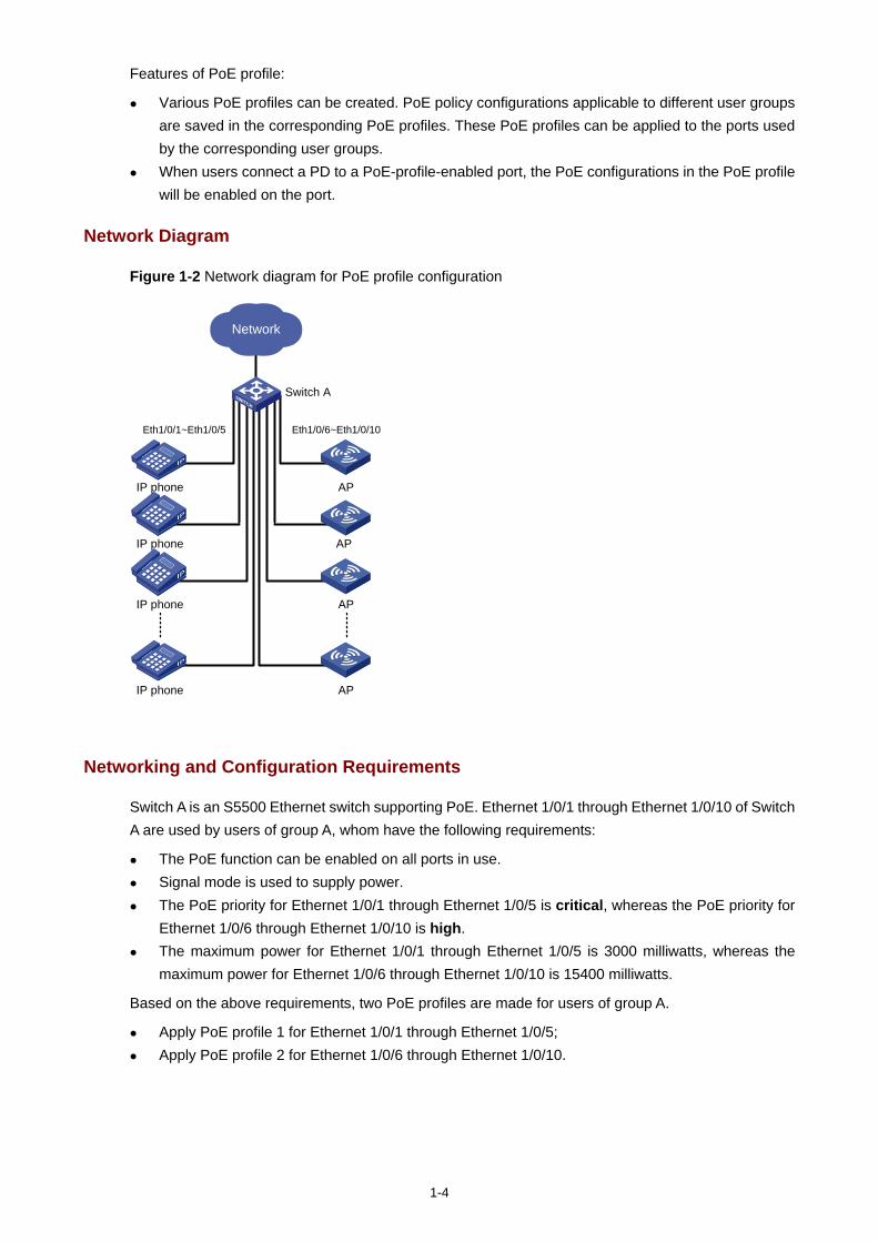
1-4
Features of PoE profile:
Various PoE profiles can be created. PoE policy configurations applicable to different user groups are saved in the corresponding PoE profiles. These PoE profiles can be applied to the ports used by the corresponding user groups.
When users connect a PD to a PoE-profile-enabled port, the PoE configurations in the PoE profile will be enabled on the port.
Network Diagram
Figure 1-2 Network diagram for PoE profile configuration
Network
IP phone
Switch A
AP
IP phone
IP phone
IP phone
AP
AP
AP
Eth1/0/1~Eth1/0/5 Eth1/0/6~Eth1/0/10
Networking and Configuration Requirements
Switch A is an S5500 Ethernet switch supporting PoE. Ethernet 1/0/1 through Ethernet 1/0/10 of Switch A are used by users of group A, whom have the following requirements:
The PoE function can be enabled on all ports in use. Signal mode is used to supply power. The PoE priority for Ethernet 1/0/1 through Ethernet 1/0/5 is critical, whereas the PoE priority for
Ethernet 1/0/6 through Ethernet 1/0/10 is high. The maximum power for Ethernet 1/0/1 through Ethernet 1/0/5 is 3000 milliwatts, whereas the
maximum power for Ethernet 1/0/6 through Ethernet 1/0/10 is 15400 milliwatts.
Based on the above requirements, two PoE profiles are made for users of group A.
Apply PoE profile 1 for Ethernet 1/0/1 through Ethernet 1/0/5; Apply PoE profile 2 for Ethernet 1/0/6 through Ethernet 1/0/10.
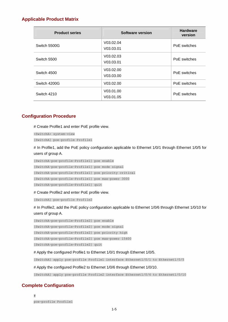
1-5
Applicable Product Matrix
Product series Software version Hardware version
Switch 5500G V03.02.04 V03.03.01
PoE switches
Switch 5500 V03.02.03 V03.03.01
PoE switches
Switch 4500 V03.02.00 V03.03.00
PoE switches
Switch 4200G V03.02.00 PoE switches
Switch 4210 V03.01.00 V03.01.05
PoE switches
Configuration Procedure
# Create Profile1 and enter PoE profile view.
<SwitchA> system-view
[SwitchA] poe-profile Profile1
# In Profile1, add the PoE policy configuration applicable to Ethernet 1/0/1 through Ethernet 1/0/5 for users of group A.
[SwitchA-poe-profile-Profile1] poe enable
[SwitchA-poe-profile-Profile1] poe mode signal
[SwitchA-poe-profile-Profile1] poe priority critical
[SwitchA-poe-profile-Profile1] poe max-power 3000
[SwitchA-poe-profile-Profile1] quit
# Create Profile2 and enter PoE profile view.
[SwitchA] poe-profile Profile2
# In Profile2, add the PoE policy configuration applicable to Ethernet 1/0/6 through Ethernet 1/0/10 for users of group A.
[SwitchA-poe-profile-Profile2] poe enable
[SwitchA-poe-profile-Profile2] poe mode signal
[SwitchA-poe-profile-Profile2] poe priority high
[SwitchA-poe-profile-Profile2] poe max-power 15400
[SwitchA-poe-profile-Profile2] quit
# Apply the configured Profile1 to Ethernet 1/0/1 through Ethernet 1/0/5.
[SwitchA] apply poe-profile Profile1 interface Ethernet1/0/1 to Ethernet1/0/5
# Apply the configured Profile2 to Ethernet 1/0/6 through Ethernet 1/0/10.
[SwitchA] apply poe-profile Profile2 interface Ethernet1/0/6 to Ethernet1/0/10
Complete Configuration
#
poe-profile Profile1

1-6
poe enable
poe max-power 3000
poe priority critical
poe-profile Profile2
poe enable
poe priority high
#
interface Ethernet1/0/1
apply poe-profile Profile1
#
interface Ethernet1/0/2
apply poe-profile Profile1
#
interface Ethernet1/0/3
apply poe-profile Profile1
#
interface Ethernet1/0/4
apply poe-profile Profile1
#
interface Ethernet1/0/5
apply poe-profile Profile1
#
interface Ethernet1/0/6
apply poe-profile Profile2
#
interface Ethernet1/0/7
apply poe-profile Profile2
#
interface Ethernet1/0/8
apply poe-profile Profile2
#
interface Ethernet1/0/9
apply poe-profile Profile2
#
interface Ethernet1/0/10
apply poe-profile Profile2
Precautions
1) When the apply poe-profile command is used to apply a PoE profile to a port, some PoE features can be applied successfully while some cannot. PoE profiles are applied to 3Com stackable PoE switches according to the following rules:
When the apply poe-profile command is used to apply a PoE profile to a port, the PoE profile is applied successfully as long as one PoE feature in the PoE profile is applied properly. When the display current-configuration command is used for query, it is displayed that the PoE profile is applied properly to the port.
If one or more features in the PoE profile are not applied properly on a port, the switch will prompt explicitly which PoE features in the PoE profile are not applied properly on which ports.

1-7
The display current-configuration command can be used to query which PoE profile is applied to a port. However, the command cannot be used to query which PoE features in a PoE profile are applied successfully.
2) If you cannot apply a PoE profile to a PoE port, it may be due to the following reasons: Some of the PoE features in the PoE profile have been configured through other modes; Some of the PoE features in the PoE profile are not compliant with the configuration requirements
for PoE ports; Another PoE profile has been applied to this PoE port.
You can solve the problem in the following ways:
In the first case, you can solve the problem by removing the original configurations. In the second case, you need to modify some configurations in the PoE profile.
In the third case, you need to remove the application of the undesired PoE profile from the PoE port.

i
Table of Contents
1 UDP Helper Configuration Guide ·············································································································1-1 UDP Helper Configuration Guide············································································································1-1
Network Diagram·····························································································································1-1 Networking and Configuration Requirements··················································································1-1 Applicable Product Matrix················································································································1-1 Configuration Procedure··················································································································1-2 Complete Configuration···················································································································1-2 Precautions······································································································································1-2
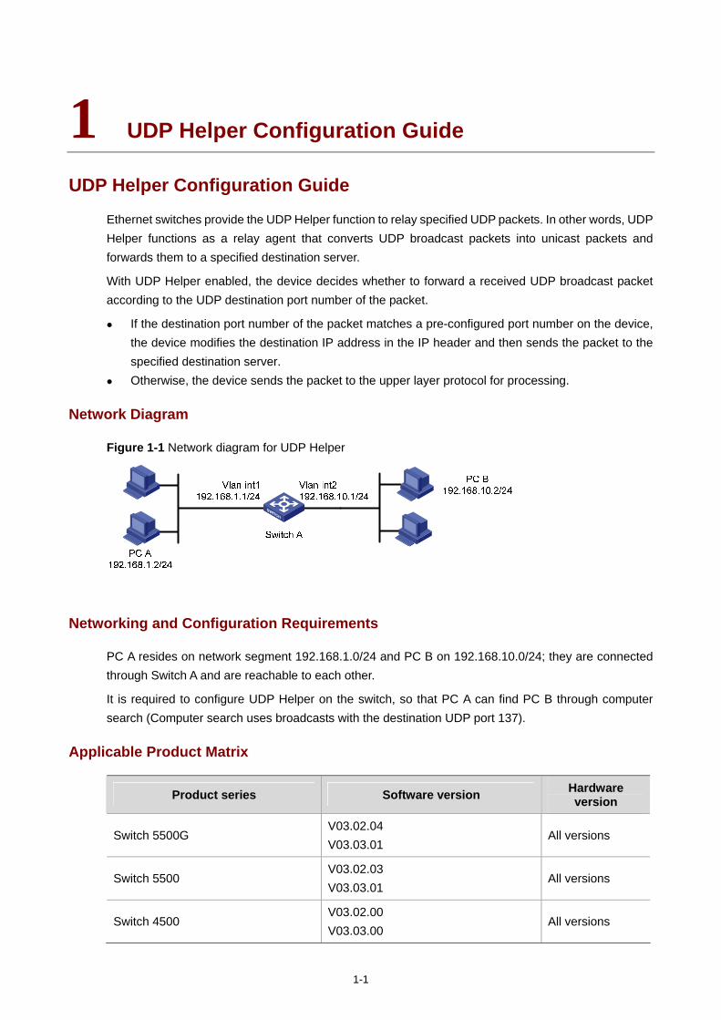
1-1
1 UDP Helper Configuration Guide
UDP Helper Configuration Guide
Ethernet switches provide the UDP Helper function to relay specified UDP packets. In other words, UDP Helper functions as a relay agent that converts UDP broadcast packets into unicast packets and forwards them to a specified destination server.
With UDP Helper enabled, the device decides whether to forward a received UDP broadcast packet according to the UDP destination port number of the packet.
If the destination port number of the packet matches a pre-configured port number on the device, the device modifies the destination IP address in the IP header and then sends the packet to the specified destination server.
Otherwise, the device sends the packet to the upper layer protocol for processing.
Network Diagram
Figure 1-1 Network diagram for UDP Helper
Networking and Configuration Requirements
PC A resides on network segment 192.168.1.0/24 and PC B on 192.168.10.0/24; they are connected through Switch A and are reachable to each other.
It is required to configure UDP Helper on the switch, so that PC A can find PC B through computer search (Computer search uses broadcasts with the destination UDP port 137).
Applicable Product Matrix
Product series Software version Hardware version
Switch 5500G V03.02.04 V03.03.01
All versions
Switch 5500 V03.02.03 V03.03.01
All versions
Switch 4500 V03.02.00 V03.03.00
All versions
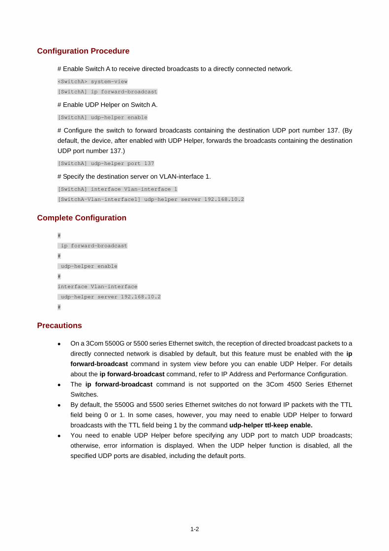
1-2
Configuration Procedure
# Enable Switch A to receive directed broadcasts to a directly connected network.
<SwitchA> system-view
[SwitchA] ip forward-broadcast
# Enable UDP Helper on Switch A.
[SwitchA] udp-helper enable
# Configure the switch to forward broadcasts containing the destination UDP port number 137. (By default, the device, after enabled with UDP Helper, forwards the broadcasts containing the destination UDP port number 137.)
[SwitchA] udp-helper port 137
# Specify the destination server on VLAN-interface 1.
[SwitchA] interface Vlan-interface 1
[SwitchA-Vlan-interface1] udp-helper server 192.168.10.2
Complete Configuration
#
ip forward-broadcast
#
udp-helper enable
#
interface Vlan-interface
udp-helper server 192.168.10.2
#
Precautions
On a 3Com 5500G or 5500 series Ethernet switch, the reception of directed broadcast packets to a directly connected network is disabled by default, but this feature must be enabled with the ip forward-broadcast command in system view before you can enable UDP Helper. For details about the ip forward-broadcast command, refer to IP Address and Performance Configuration.
The ip forward-broadcast command is not supported on the 3Com 4500 Series Ethernet Switches.
By default, the 5500G and 5500 series Ethernet switches do not forward IP packets with the TTL field being 0 or 1. In some cases, however, you may need to enable UDP Helper to forward broadcasts with the TTL field being 1 by the command udp-helper ttl-keep enable.
You need to enable UDP Helper before specifying any UDP port to match UDP broadcasts; otherwise, error information is displayed. When the UDP helper function is disabled, all the specified UDP ports are disabled, including the default ports.

i
Table of Contents
1 SNMP-RMON Configuration Guide ··········································································································1-1 SNMP Configuration ·······························································································································1-1
Network Diagram·····························································································································1-1 Networking and Configuration Requirements··················································································1-1 Applicable Product Matrix················································································································1-1 Configuration Procedure··················································································································1-2 Complete Configuration···················································································································1-2 Precautions······································································································································1-3
RMON Configuration·······························································································································1-3 Network Diagram·····························································································································1-3 Networking and Configuration Requirements··················································································1-3 Applicable Product Matrix················································································································1-4 Configuration Procedure··················································································································1-4 Complete Configuration···················································································································1-4 Precautions······································································································································1-5
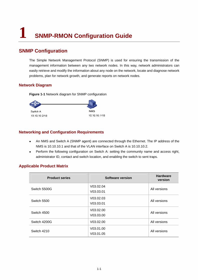
1-1
1 SNMP-RMON Configuration Guide
SNMP Configuration
The Simple Network Management Protocol (SNMP) is used for ensuring the transmission of the management information between any two network nodes. In this way, network administrators can easily retrieve and modify the information about any node on the network, locate and diagnose network problems, plan for network growth, and generate reports on network nodes.
Network Diagram
Figure 1-1 Network diagram for SNMP configuration
Networking and Configuration Requirements
An NMS and Switch A (SNMP agent) are connected through the Ethernet. The IP address of the NMS is 10.10.10.1 and that of the VLAN interface on Switch A is 10.10.10.2.
Perform the following configuration on Switch A: setting the community name and access right, administrator ID, contact and switch location, and enabling the switch to sent traps.
Applicable Product Matrix
Product series Software version Hardware version
Switch 5500G V03.02.04 V03.03.01
All versions
Switch 5500 V03.02.03 V03.03.01
All versions
Switch 4500 V03.02.00 V03.03.00
All versions
Switch 4200G V03.02.00 All versions
Switch 4210 V03.01.00 V03.01.05
All versions
1-2
Configuration Procedure
Configuring the switch (SNMP agent)
# Enable SNMP agent, and set the SNMPv1 and SNMPv2c community names.
<Sysname> system-view
[Sysname] snmp-agent
[Sysname] snmp-agent sys-info version all
[Sysname] snmp-agent community read readname
[Sysname] snmp-agent community write writename
# Set the access right of the NMS to the MIB of the SNMP agent.
[Sysname] snmp-agent mib-view include internet 1.3.6.1
# For SNMPv3, set the SNMPv3 group and user, set the security level to authentication with privacy, authentication protocol to HMAC-MD5, authentication password to passmd5, encryption protocol to DES, and encryption password to cfb128cfb128.
[Sysname] snmp-agent group v3 managev3group privacy write-view internet
[Sysname] snmp-agent usm-user v3 managev3user managev3group authentication-mode md5 passmd5
privacy-mode des56 cfb128cfb128
# Configure the IP address of VLAN-interface 2 as 10.10.10.2. Add the port Ethernet 1/0/2 to VLAN 2.
[Sysname] vlan 2
[Sysname-vlan2] port Ethernet 1/0/2
[Sysname-vlan2] quit
[Sysname] interface Vlan-interface 2
[Sysname-Vlan-interface2] ip address 10.10.10.2 255.255.255.0
[Sysname-Vlan-interface2] quit
# Enable the sending of Traps to the NMS with an IP address of 10.10.10.1, using public as the community name.
[Sysname] snmp-agent trap enable standard authentication
[Sysname] snmp-agent trap enable standard coldstart
[Sysname] snmp-agent trap enable standard linkup
[Sysname] snmp-agent trap enable standard linkdown
[Sysname] snmp-agent target-host trap address udp-domain 10.10.10.1 udp-port 5000 params
securityname public
Configuring the NMS
The 3Com series Ethernet switches support 3Com Intelligent Management Center (iMC). When you use iMC, you need to set usernames and choose the security level. For each security level, you need to set authentication mode, authentication password, privacy mode, privacy password, and so on. In addition, you need to set timeout time and maximum retry times.
You can query and configure an Ethernet switch through the NMS.
Complete Configuration
#
interface Vlan-interface2
ip address 10.10.10.2 255.255.0.0
#
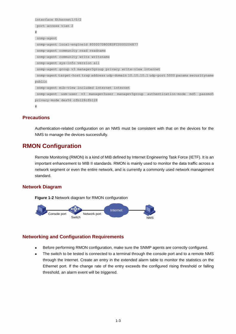
1-3
interface Ethernet1/0/2
port access vlan 2
#
snmp-agent
snmp-agent local-engineid 800007DB00E0FC0000206877
snmp-agent community read readname
snmp-agent community write writename
snmp-agent sys-info version all
snmp-agent group v3 managev3group privacy write-view internet
snmp-agent target-host trap address udp-domain 10.10.10.1 udp-port 5000 params securityname
public
snmp-agent mib-view included internet internet
snmp-agent usm-user v3 managev3user managev3group authentication-mode md5 passmd5
privacy-mode des56 cfb128cfb128
#
Precautions
Authentication-related configuration on an NMS must be consistent with that on the devices for the NMS to manage the devices successfully.
RMON Configuration
Remote Monitoring (RMON) is a kind of MIB defined by Internet Engineering Task Force (IETF). It is an important enhancement to MIB II standards. RMON is mainly used to monitor the data traffic across a network segment or even the entire network, and is currently a commonly used network management standard.
Network Diagram
Figure 1-2 Network diagram for RMON configuration
Console portSwitch
InternetNetwork port
NMS
Networking and Configuration Requirements
Before performing RMON configuration, make sure the SNMP agents are correctly configured. The switch to be tested is connected to a terminal through the console port and to a remote NMS
through the Internet. Create an entry in the extended alarm table to monitor the statistics on the Ethernet port. If the change rate of the entry exceeds the configured rising threshold or falling threshold, an alarm event will be triggered.
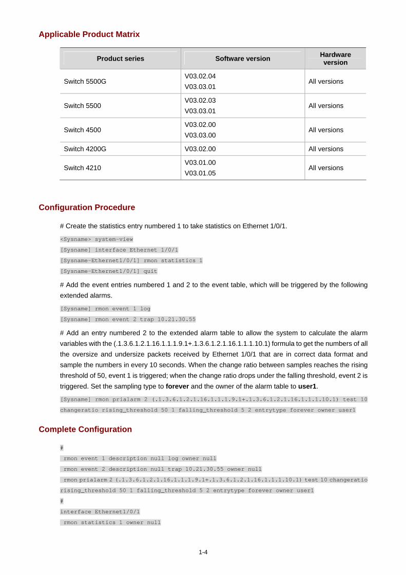
1-4
Applicable Product Matrix
Product series Software version Hardware version
Switch 5500G V03.02.04 V03.03.01
All versions
Switch 5500 V03.02.03 V03.03.01
All versions
Switch 4500 V03.02.00 V03.03.00
All versions
Switch 4200G V03.02.00 All versions
Switch 4210 V03.01.00 V03.01.05
All versions
Configuration Procedure
# Create the statistics entry numbered 1 to take statistics on Ethernet 1/0/1.
<Sysname> system-view
[Sysname] interface Ethernet 1/0/1
[Sysname-Ethernet1/0/1] rmon statistics 1
[Sysname-Ethernet1/0/1] quit
# Add the event entries numbered 1 and 2 to the event table, which will be triggered by the following extended alarms.
[Sysname] rmon event 1 log
[Sysname] rmon event 2 trap 10.21.30.55
# Add an entry numbered 2 to the extended alarm table to allow the system to calculate the alarm variables with the (.1.3.6.1.2.1.16.1.1.1.9.1+.1.3.6.1.2.1.16.1.1.1.10.1) formula to get the numbers of all the oversize and undersize packets received by Ethernet 1/0/1 that are in correct data format and sample the numbers in every 10 seconds. When the change ratio between samples reaches the rising threshold of 50, event 1 is triggered; when the change ratio drops under the falling threshold, event 2 is triggered. Set the sampling type to forever and the owner of the alarm table to user1.
[Sysname] rmon prialarm 2 (.1.3.6.1.2.1.16.1.1.1.9.1+.1.3.6.1.2.1.16.1.1.1.10.1) test 10
changeratio rising_threshold 50 1 falling_threshold 5 2 entrytype forever owner user1
Complete Configuration
#
rmon event 1 description null log owner null
rmon event 2 description null trap 10.21.30.55 owner null
rmon prialarm 2 (.1.3.6.1.2.1.16.1.1.1.9.1+.1.3.6.1.2.1.16.1.1.1.10.1) test 10 changeratio
rising_threshold 50 1 falling_threshold 5 2 entrytype forever owner user1
#
interface Ethernet1/0/1
rmon statistics 1 owner null

1-5
Precautions
None
i
Table of Contents
1 NTP Configuration Guide··························································································································1-1 NTP Client/Server Mode Configuration···································································································1-1
Network Diagram·····························································································································1-1 Networking and Configuration Requirements··················································································1-1 Applicable Product Matrix················································································································1-1 Configuration Procedure··················································································································1-1 Complete Configuration···················································································································1-2 Precautions······································································································································1-2
NTP Symmetric Peers Mode Configuration····························································································1-2 Network Diagram·····························································································································1-2 Networking and Configuration Requirements··················································································1-2 Applicable Product Matrix················································································································1-3 Configuration Procedure··················································································································1-3 Complete Configuration···················································································································1-3 Precautions······································································································································1-3
NTP Broadcast Mode Configuration ·······································································································1-4 Network Diagram·····························································································································1-4 Networking and Configuration Requirements··················································································1-4 Applicable Product Matrix················································································································1-4 Configuration Procedure··················································································································1-4 Complete Configuration···················································································································1-5 Precautions······································································································································1-5
NTP Multicast Mode Configuration ·········································································································1-6 Network Diagram·····························································································································1-6 Networking and Configuration Requirements··················································································1-6 Applicable Product Matrix················································································································1-6 Configuration Procedure··················································································································1-6 Complete Configuration···················································································································1-7 Precautions······································································································································1-7
NTP Client/Server Mode with Authentication Configuration ···································································1-7 Network Diagram·····························································································································1-7 Networking and Configuration Requirements··················································································1-8 Applicable Product Matrix················································································································1-8 Configuration Procedure··················································································································1-8 Complete Configuration···················································································································1-9 Precautions······································································································································1-9
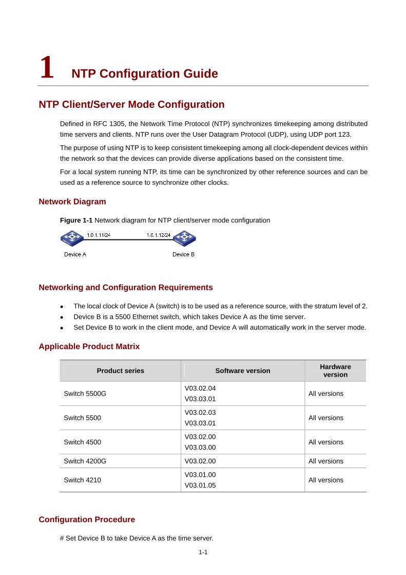
1-1
1 NTP Configuration Guide
NTP Client/Server Mode Configuration
Defined in RFC 1305, the Network Time Protocol (NTP) synchronizes timekeeping among distributed time servers and clients. NTP runs over the User Datagram Protocol (UDP), using UDP port 123.
The purpose of using NTP is to keep consistent timekeeping among all clock-dependent devices within the network so that the devices can provide diverse applications based on the consistent time.
For a local system running NTP, its time can be synchronized by other reference sources and can be used as a reference source to synchronize other clocks.
Network Diagram
Figure 1-1 Network diagram for NTP client/server mode configuration
Networking and Configuration Requirements
The local clock of Device A (switch) is to be used as a reference source, with the stratum level of 2. Device B is a 5500 Ethernet switch, which takes Device A as the time server. Set Device B to work in the client mode, and Device A will automatically work in the server mode.
Applicable Product Matrix
Product series Software version Hardware version
Switch 5500G V03.02.04 V03.03.01
All versions
Switch 5500 V03.02.03 V03.03.01
All versions
Switch 4500 V03.02.00 V03.03.00
All versions
Switch 4200G V03.02.00 All versions
Switch 4210 V03.01.00 V03.01.05
All versions
Configuration Procedure
# Set Device B to take Device A as the time server.
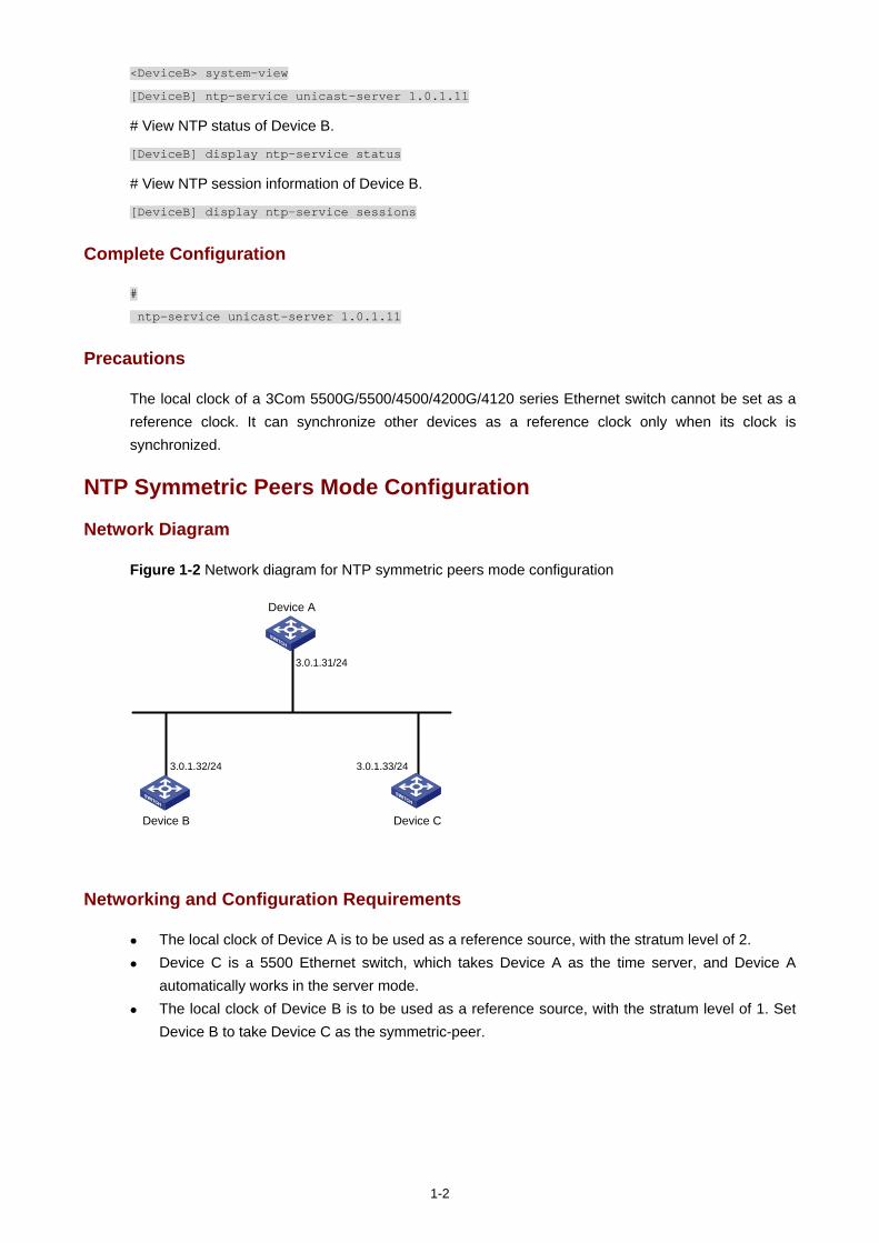
1-2
<DeviceB> system-view
[DeviceB] ntp-service unicast-server 1.0.1.11
# View NTP status of Device B.
[DeviceB] display ntp-service status
# View NTP session information of Device B.
[DeviceB] display ntp-service sessions
Complete Configuration
#
ntp-service unicast-server 1.0.1.11
Precautions
The local clock of a 3Com 5500G/5500/4500/4200G/4120 series Ethernet switch cannot be set as a reference clock. It can synchronize other devices as a reference clock only when its clock is synchronized.
NTP Symmetric Peers Mode Configuration
Network Diagram
Figure 1-2 Network diagram for NTP symmetric peers mode configuration
Device A
Device B Device C
3.0.1.31/24
3.0.1.32/24 3.0.1.33/24
Networking and Configuration Requirements
The local clock of Device A is to be used as a reference source, with the stratum level of 2. Device C is a 5500 Ethernet switch, which takes Device A as the time server, and Device A
automatically works in the server mode. The local clock of Device B is to be used as a reference source, with the stratum level of 1. Set
Device B to take Device C as the symmetric-peer.
1-3
Applicable Product Matrix
Product series Software version Hardware version
Switch 5500G V03.02.04 V03.03.01
All versions
Switch 5500 V03.02.03 V03.03.01
All versions
Switch 4500 V03.02.00 V03.03.00
All versions
Switch 4200G V03.02.00 All versions
Switch 4210 V03.01.00 V03.01.05
All versions
Configuration Procedure
Configure Device C.
# Set Device A as the time server.
<DeviceC> system-view
[DeviceC] ntp-service unicast-server 3.0.1.31
Configure Device B (after Device C is synchronized to Device A).
# Set Device C as the symmetric-peer.
<DeviceB> system-view
[DeviceB] ntp-service unicast-peer 3.0.1.33
# View NTP status and NTP session information of Device C after clock synchronization.
[DeviceC] display ntp-service status
[DeviceC] display ntp-service sessions
Complete Configuration
Configuration on Device C. #
ntp-service unicast-server 3.0.1.31
Configuration on Device B. #
ntp-service unicast-peer 3.0.1.33
Precautions
The local clock of a 3Com 5500G/5500/4500/4200G/4120 series Ethernet switch cannot be set as a reference clock. It can synchronize other devices as a reference clock only when its clock is synchronized.

1-4
NTP Broadcast Mode Configuration
Network Diagram
Figure 1-3 Network diagram for NTP broadcast mode configuration
Vlan-int23.0.1.11/24
Vlan-int23.0.1.12/24
Vlan-int23.0.1.13/24
Vlan-int23.0.1.14/24
Vlan-int23.0.1.12/24
Device A Device B
Device C
Device D
Networking and Configuration Requirements
The local clock of Device C is to be used as a reference source, with the stratum level of 2. Set Device C to work in the broadcast server mode and send broadcasts through its VLAN-interface 2.
Device A and Device D are two 5500 Ethernet switches. Set Device A and Device D to work in the broadcast client mode and listen to broadcasts through their VLAN-interface 2 respectively.
Applicable Product Matrix
Product series Software version Hardware version
Switch 5500G V03.02.04 V03.03.01
All versions
Switch 5500 V03.02.03 V03.03.01
All versions
Switch 4500 V03.02.00 V03.03.00
All versions
Switch 4200G V03.02.00 All versions
Switch 4210 V03.01.00 V03.01.05
All versions
Configuration Procedure
Configure Device C.
# Set Device C to work as the broadcast sever and send broadcasts through its VLAN-interface 2.
<DeviceC> system-view
[DeviceC] interface Vlan-interface 2
1-5
[DeviceC-Vlan-interface2] ntp-service broadcast-server
Configure Device A (perform the same configuration on Device D).
# Set Device A to work as the broadcast client and listen broadcasts through its VLAN-interface 2.
<DeviceA> system-view
[DeviceA] interface Vlan-interface 2
[DeviceA-Vlan-interface2] ntp-service broadcast-client
View the NTP status and NTP session information of Device D after clock synchronization. (You can use the same command to view the NTP status and NTP session information of Device A)
# View NTP status of Device D.
[DeviceD] display ntp-service status
# View NTP session information of Device D.
[DeviceD] display ntp-service sessions
Complete Configuration
Configuration on Device C. #
interface Vlan-interface2
ip address 3.0.1.13 255.255.255.0
ntp-service broadcast-server
Configuration on Device A. #
interface Vlan-interface2
ip address 3.0.1.11 255.255.255.0
ntp-service broadcast-client
Configuration on Device D. #
interface Vlan-interface2
ip address 3.0.1.14 255.255.255.0
ntp-service broadcast-client
Precautions
The local clock of a 3Com 5500G/5500/4500/4200G/4120 series Ethernet switch cannot be set as a reference clock. It can synchronize other devices as a reference clock only when its clock is synchronized.
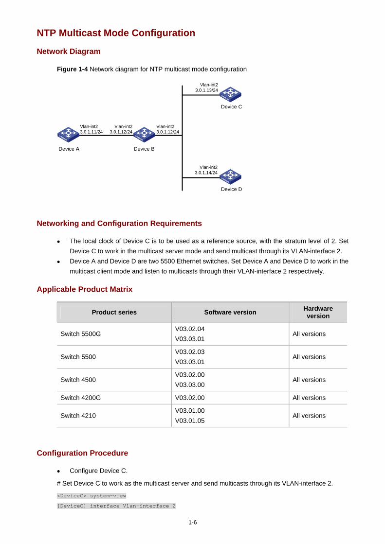
1-6
NTP Multicast Mode Configuration
Network Diagram
Figure 1-4 Network diagram for NTP multicast mode configuration
Vlan-int23.0.1.11/24
Vlan-int23.0.1.12/24
Vlan-int23.0.1.13/24
Vlan-int23.0.1.14/24
Vlan-int23.0.1.12/24
Device A Device B
Device C
Device D
Networking and Configuration Requirements
The local clock of Device C is to be used as a reference source, with the stratum level of 2. Set Device C to work in the multicast server mode and send multicast through its VLAN-interface 2.
Device A and Device D are two 5500 Ethernet switches. Set Device A and Device D to work in the multicast client mode and listen to multicasts through their VLAN-interface 2 respectively.
Applicable Product Matrix
Product series Software version Hardware version
Switch 5500G V03.02.04 V03.03.01
All versions
Switch 5500 V03.02.03 V03.03.01
All versions
Switch 4500 V03.02.00 V03.03.00
All versions
Switch 4200G V03.02.00 All versions
Switch 4210 V03.01.00 V03.01.05
All versions
Configuration Procedure
Configure Device C.
# Set Device C to work as the multicast server and send multicasts through its VLAN-interface 2.
<DeviceC> system-view
[DeviceC] interface Vlan-interface 2
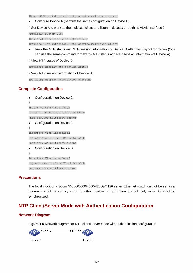
1-7
[DeviceC-Vlan-interface2] ntp-service multicast-server
Configure Device A (perform the same configuration on Device D).
# Set Device A to work as the multicast client and listen multicasts through its VLAN-interface 2.
<DeviceA> system-view
[DeviceA] interface Vlan-interface 2
[DeviceA-Vlan-interface2] ntp-service multicast-client
View the NTP status and NTP session information of Device D after clock synchronization (You can use the same command to view the NTP status and NTP session information of Device A).
# View NTP status of Device D.
[DeviceD] display ntp-service status
# View NTP session information of Device D.
[DeviceD] display ntp-service sessions
Complete Configuration
Configuration on Device C. #
interface Vlan-interface2
ip address 3.0.1.13 255.255.255.0
ntp-service multicast-server
Configuration on Device A. #
interface Vlan-interface2
ip address 1.0.1.11 255.255.255.0
ntp-service multicast-client
Configuration on Device D. #
interface Vlan-interface2
ip address 3.0.1.14 255.255.255.0
ntp-service multicast-client
Precautions
The local clock of a 3Com 5500G/5500/4500/4200G/4120 series Ethernet switch cannot be set as a reference clock. It can synchronize other devices as a reference clock only when its clock is synchronized.
NTP Client/Server Mode with Authentication Configuration
Network Diagram
Figure 1-5 Network diagram for NTP client/server mode with authentication configuration
1-8
Networking and Configuration Requirements
The local clock of Device A is to be used as a reference source, with the stratum level of 2. Device B is a 5500 Ethernet switch, which takes Device A as the time server and works in the client
mode. Device A automatically works in the server mode. Configure NTP authentication between Device A and Device B.
Applicable Product Matrix
Product series Software version Hardware version
Switch 5500G V03.02.04 V03.03.01
All versions
Switch 5500 V03.02.03 V03.03.01
All versions
Switch 4500 V03.02.00 V03.03.00
All versions
Switch 4200G V03.02.00 All versions
Switch 4210 V03.01.00 V03.01.05
All versions
Configuration Procedure
Configure Device B.
# Set Device A as the time server.
<DeviceB> system-view
[DeviceB] ntp-service unicast-server 1.0.1.11
# Enable the NTP authentication function.
[DeviceB] ntp-service authentication enable
# Set MD5 key numbered 42, with the key content aNiceKey.
[DeviceB] ntp-service authentication-keyid 42 authentication-mode md5 aNiceKey
# Specify key 42 as a trusted key.
[DeviceB] ntp-service reliable authentication-keyid 42
[DeviceB] ntp-service unicast-server 1.0.1.11 authentication-keyid 42
Configure Device A.
# Enable the NTP authentication function.
<DeviceA> system-view
[DeviceA] ntp-service authentication enable
# Set MD5 key numbered 42, with the key content aNiceKey.
[DeviceA] ntp-service authentication-keyid 42 authentication-mode md5 aNiceKey
# Specify key 42 as a trusted key.
[DeviceA] ntp-service reliable authentication-keyid 42
1-9
Complete Configuration
Configuration on Device B. #
ntp-service authentication enable
ntp-service authentication-keyid 42 authentication-mode md5 X&9#$^U(!:[Q=^Q`MAF4<1!!
ntp-service reliable authentication-keyid 42
ntp-service unicast-server 1.0.1.11
Configuration on Device A. #
ntp-service authentication enable
ntp-service authentication-keyid 42 authentication-mode md5 X&9#$^U(!:[Q=^Q`MAF4<1!!
ntp-service reliable authentication-keyid 42
Precautions
The local clock of a 3Com 5500G/5500/4500/4200G/4120 series Ethernet switch cannot be set as a reference clock.
i
Table of Contents
1 SSH Configuration Guide ·························································································································1-1 Configuring the Switch to Act as the SSH Server and Use Password Authentication ···························1-1
Network Diagram·····························································································································1-1 Networking and Configuration Requirements··················································································1-1 Applicable Product Matrix················································································································1-1 Configuration Procedure··················································································································1-1 Complete Configuration···················································································································1-4 Precautions······································································································································1-4
Configuring the Switch to Act as the SSH Server and Use RSA Authentication····································1-4 Network Diagram·····························································································································1-4 Networking and Configuration Requirements··················································································1-4 Applicable Product Matrix················································································································1-5 Configuration Procedure··················································································································1-5 Complete Configuration·················································································································1-10 Precautions····································································································································1-10
Configuring the Switch to Act as the SSH Client and Use Password Authentication···························1-10 Network Diagram···························································································································1-10 Networking and Configuration Requirements················································································1-10 Applicable Product Matrix··············································································································1-10 Configuration Procedure················································································································1-11 Complete Configuration·················································································································1-12 Precautions····································································································································1-12
Configuring the Switch to Act as the SSH Client and Use RSA Authentication ···································1-13 Network Diagram···························································································································1-13 Networking and Configuration Requirements················································································1-13 Applicable Product Matrix··············································································································1-13 Configuration Procedure················································································································1-13 Complete Configuration·················································································································1-15 Precautions····································································································································1-16
Configuring the Switch to Act as the SSH Client and Not to Support First-Time Authentication··········1-16 Network Diagram···························································································································1-16 Networking and Configuration Requirements················································································1-16 Applicable Product Matrix··············································································································1-17 Configuration Procedure················································································································1-17 Complete Configuration·················································································································1-20 Precautions····································································································································1-21
Configuring SFTP··································································································································1-21 Network Diagram···························································································································1-21 Networking and Configuration Requirements················································································1-21 Applicable Product Matrix··············································································································1-22 Configuration Procedure················································································································1-22 Complete Configuration·················································································································1-24 Precautions····································································································································1-25
ii
When Switch Acts as Server for Password Authentication···································································1-25 Network Diagram···························································································································1-25 Networking and Configuration Requirements················································································1-25 Applicable Product Matrix··············································································································1-25 Configuration Procedure················································································································1-25 Complete Configuration·················································································································1-28 Precautions····································································································································1-28
When Switch Acts as Server for Publickey Authentication ···································································1-28 Network Diagram···························································································································1-28 Networking and Configuration Requirements················································································1-29 Applicable Product Matrix··············································································································1-29 Configuration Procedure················································································································1-29 Complete Configuration·················································································································1-34 Precautions····································································································································1-35
When Switch Acts as Client for Password Authentication····································································1-35 Network Diagram···························································································································1-35 Networking and Configuration Requirements················································································1-35 Applicable Product Matrix··············································································································1-35 Configuration Procedure················································································································1-35 Complete Configuration·················································································································1-37 Precautions····································································································································1-37
When Switch Acts as Client for Publickey Authentication ····································································1-38 Network Diagram···························································································································1-38 Networking and Configuration Requirements················································································1-38 Applicable Product Matrix··············································································································1-38 Configuration Procedure················································································································1-38 Complete Configuration·················································································································1-40 Precautions····································································································································1-41
When Switch Acts as Client and First-Time Authentication is not Supported ······································1-41 Network Diagram···························································································································1-41 Networking and Configuration Requirements················································································1-41 Applicable Product Matrix··············································································································1-41 Configuration Procedure················································································································1-42 Complete Configuration·················································································································1-44 Precautions····································································································································1-45
SFTP Configuration·······························································································································1-45 Network Diagram···························································································································1-45 Networking and Configuration Requirements················································································1-45 Applicable Product Matrix··············································································································1-46 Configuration Procedure················································································································1-46 Complete Configuration·················································································································1-49 Precautions····································································································································1-49
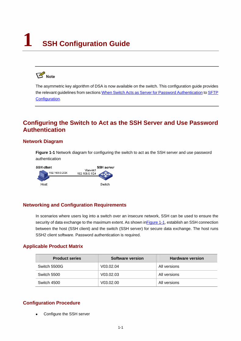
1-1
1 SSH Configuration Guide
The asymmetric key algorithm of DSA is now available on the switch. This configuration guide provides the relevant guidelines from sections When Switch Acts as Server for Password Authentication to SFTP Configuration.
Configuring the Switch to Act as the SSH Server and Use Password Authentication
Network Diagram
Figure 1-1 Network diagram for configuring the switch to act as the SSH server and use password authentication
Networking and Configuration Requirements
In scenarios where users log into a switch over an insecure network, SSH can be used to ensure the security of data exchange to the maximum extent. As shown inFigure 1-1, establish an SSH connection between the host (SSH client) and the switch (SSH server) for secure data exchange. The host runs SSH2 client software. Password authentication is required.
Applicable Product Matrix
Product series Software version Hardware version
Switch 5500G V03.02.04 All versions
Switch 5500 V03.02.03 All versions
Switch 4500 V03.02.00 All versions
Configuration Procedure
Configure the SSH server
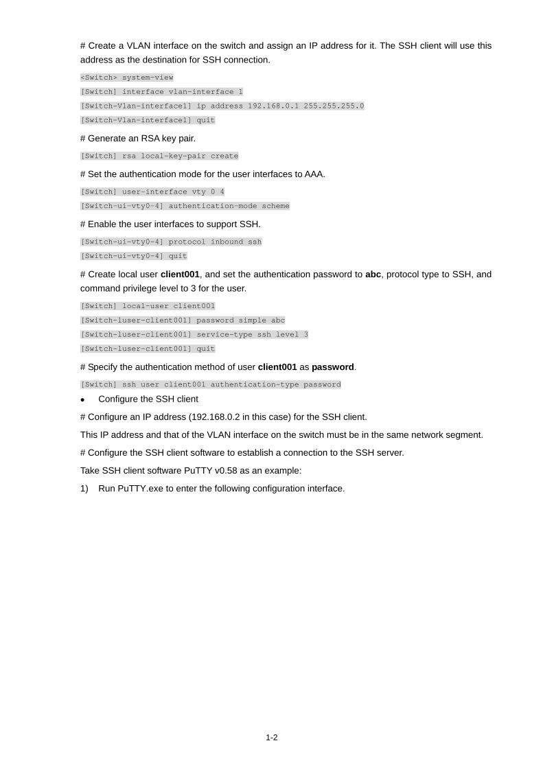
1-2
# Create a VLAN interface on the switch and assign an IP address for it. The SSH client will use this address as the destination for SSH connection.
<Switch> system-view
[Switch] interface vlan-interface 1
[Switch-Vlan-interface1] ip address 192.168.0.1 255.255.255.0
[Switch-Vlan-interface1] quit
# Generate an RSA key pair.
[Switch] rsa local-key-pair create
# Set the authentication mode for the user interfaces to AAA.
[Switch] user-interface vty 0 4
[Switch-ui-vty0-4] authentication-mode scheme
# Enable the user interfaces to support SSH.
[Switch-ui-vty0-4] protocol inbound ssh
[Switch-ui-vty0-4] quit
# Create local user client001, and set the authentication password to abc, protocol type to SSH, and command privilege level to 3 for the user.
[Switch] local-user client001
[Switch-luser-client001] password simple abc
[Switch-luser-client001] service-type ssh level 3
[Switch-luser-client001] quit
# Specify the authentication method of user client001 as password.
[Switch] ssh user client001 authentication-type password
Configure the SSH client
# Configure an IP address (192.168.0.2 in this case) for the SSH client.
This IP address and that of the VLAN interface on the switch must be in the same network segment.
# Configure the SSH client software to establish a connection to the SSH server.
Take SSH client software PuTTY v0.58 as an example:
1) Run PuTTY.exe to enter the following configuration interface.
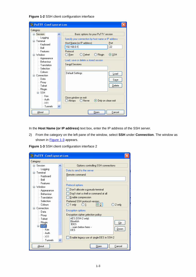
1-3
Figure 1-2 SSH client configuration interface
In the Host Name (or IP address) text box, enter the IP address of the SSH server.
2) From the category on the left pane of the window, select SSH under Connection. The window as shown in Figure 1-3 appears.
Figure 1-3 SSH client configuration interface 2
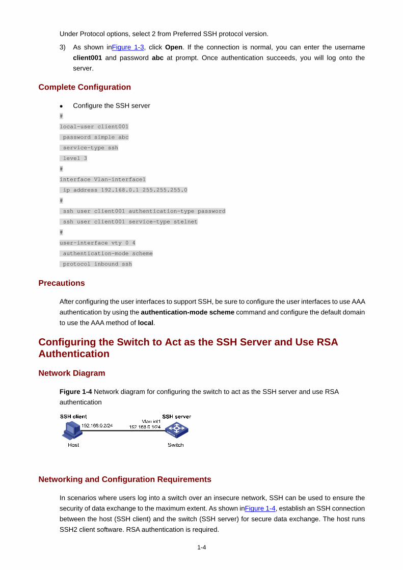
1-4
Under Protocol options, select 2 from Preferred SSH protocol version.
3) As shown inFigure 1-3, click Open. If the connection is normal, you can enter the username client001 and password abc at prompt. Once authentication succeeds, you will log onto the server.
Complete Configuration
Configure the SSH server #
local-user client001
password simple abc
service-type ssh
level 3
#
interface Vlan-interface1
ip address 192.168.0.1 255.255.255.0
#
ssh user client001 authentication-type password
ssh user client001 service-type stelnet
#
user-interface vty 0 4
authentication-mode scheme
protocol inbound ssh
Precautions
After configuring the user interfaces to support SSH, be sure to configure the user interfaces to use AAA authentication by using the authentication-mode scheme command and configure the default domain to use the AAA method of local.
Configuring the Switch to Act as the SSH Server and Use RSA Authentication
Network Diagram
Figure 1-4 Network diagram for configuring the switch to act as the SSH server and use RSA authentication
Networking and Configuration Requirements
In scenarios where users log into a switch over an insecure network, SSH can be used to ensure the security of data exchange to the maximum extent. As shown inFigure 1-4, establish an SSH connection between the host (SSH client) and the switch (SSH server) for secure data exchange. The host runs SSH2 client software. RSA authentication is required.
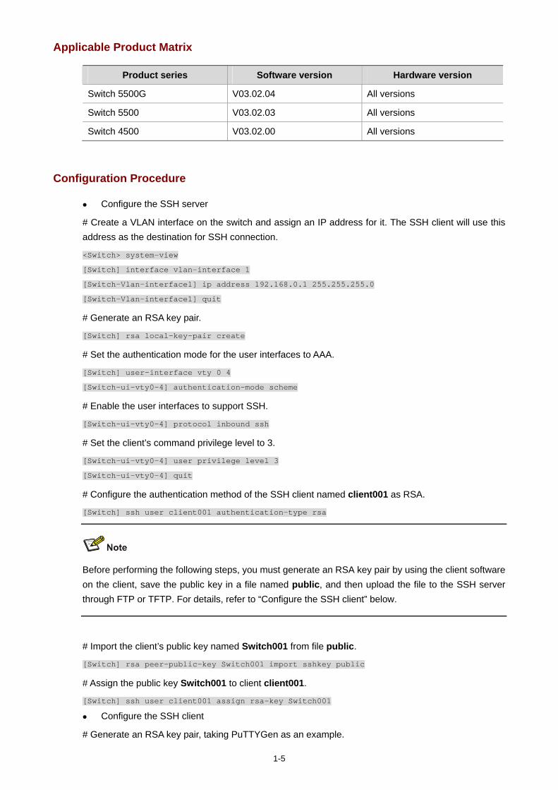
1-5
Applicable Product Matrix
Product series Software version Hardware version
Switch 5500G V03.02.04 All versions
Switch 5500 V03.02.03 All versions
Switch 4500 V03.02.00 All versions
Configuration Procedure
Configure the SSH server
# Create a VLAN interface on the switch and assign an IP address for it. The SSH client will use this address as the destination for SSH connection.
<Switch> system-view
[Switch] interface vlan-interface 1
[Switch-Vlan-interface1] ip address 192.168.0.1 255.255.255.0
[Switch-Vlan-interface1] quit
# Generate an RSA key pair.
[Switch] rsa local-key-pair create
# Set the authentication mode for the user interfaces to AAA.
[Switch] user-interface vty 0 4
[Switch-ui-vty0-4] authentication-mode scheme
# Enable the user interfaces to support SSH.
[Switch-ui-vty0-4] protocol inbound ssh
# Set the client’s command privilege level to 3.
[Switch-ui-vty0-4] user privilege level 3
[Switch-ui-vty0-4] quit
# Configure the authentication method of the SSH client named client001 as RSA.
[Switch] ssh user client001 authentication-type rsa
Before performing the following steps, you must generate an RSA key pair by using the client software on the client, save the public key in a file named public, and then upload the file to the SSH server through FTP or TFTP. For details, refer to “Configure the SSH client” below.
# Import the client’s public key named Switch001 from file public.
[Switch] rsa peer-public-key Switch001 import sshkey public
# Assign the public key Switch001 to client client001.
[Switch] ssh user client001 assign rsa-key Switch001
Configure the SSH client
# Generate an RSA key pair, taking PuTTYGen as an example.
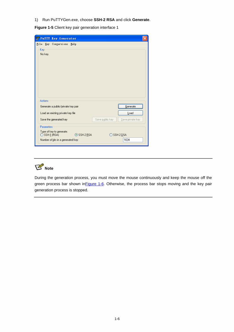
1-6
1) Run PuTTYGen.exe, choose SSH-2 RSA and click Generate.
Figure 1-5 Client key pair generation interface 1
During the generation process, you must move the mouse continuously and keep the mouse off the green process bar shown inFigure 1-6. Otherwise, the process bar stops moving and the key pair generation process is stopped.
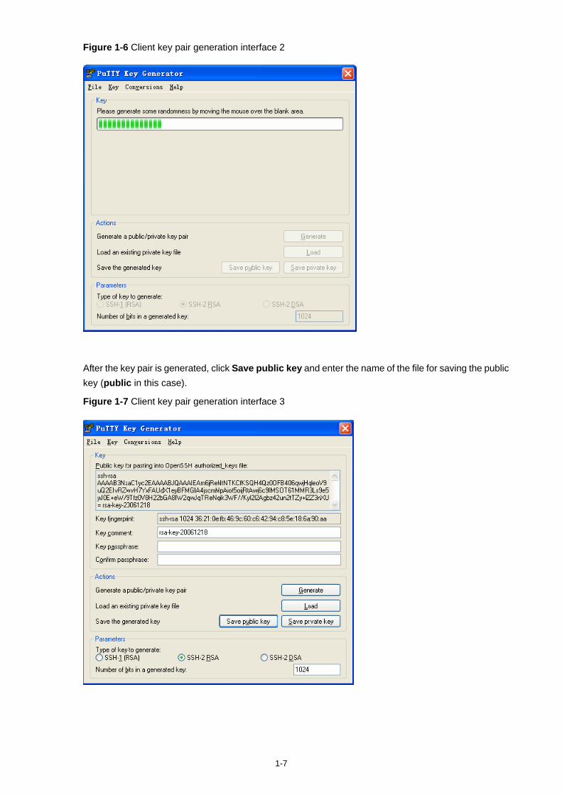
1-7
Figure 1-6 Client key pair generation interface 2
After the key pair is generated, click Save public key and enter the name of the file for saving the public key (public in this case).
Figure 1-7 Client key pair generation interface 3
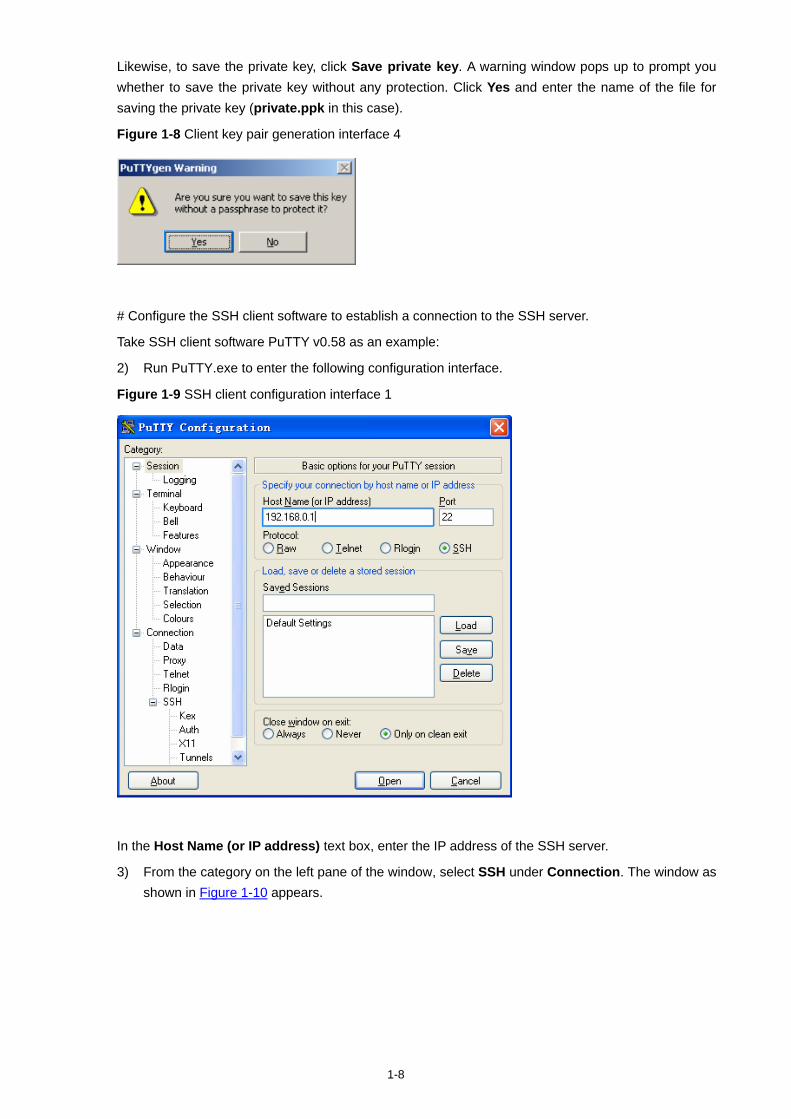
1-8
Likewise, to save the private key, click Save private key. A warning window pops up to prompt you whether to save the private key without any protection. Click Yes and enter the name of the file for saving the private key (private.ppk in this case).
Figure 1-8 Client key pair generation interface 4
# Configure the SSH client software to establish a connection to the SSH server.
Take SSH client software PuTTY v0.58 as an example:
2) Run PuTTY.exe to enter the following configuration interface.
Figure 1-9 SSH client configuration interface 1
In the Host Name (or IP address) text box, enter the IP address of the SSH server.
3) From the category on the left pane of the window, select SSH under Connection. The window as shown in Figure 1-10 appears.
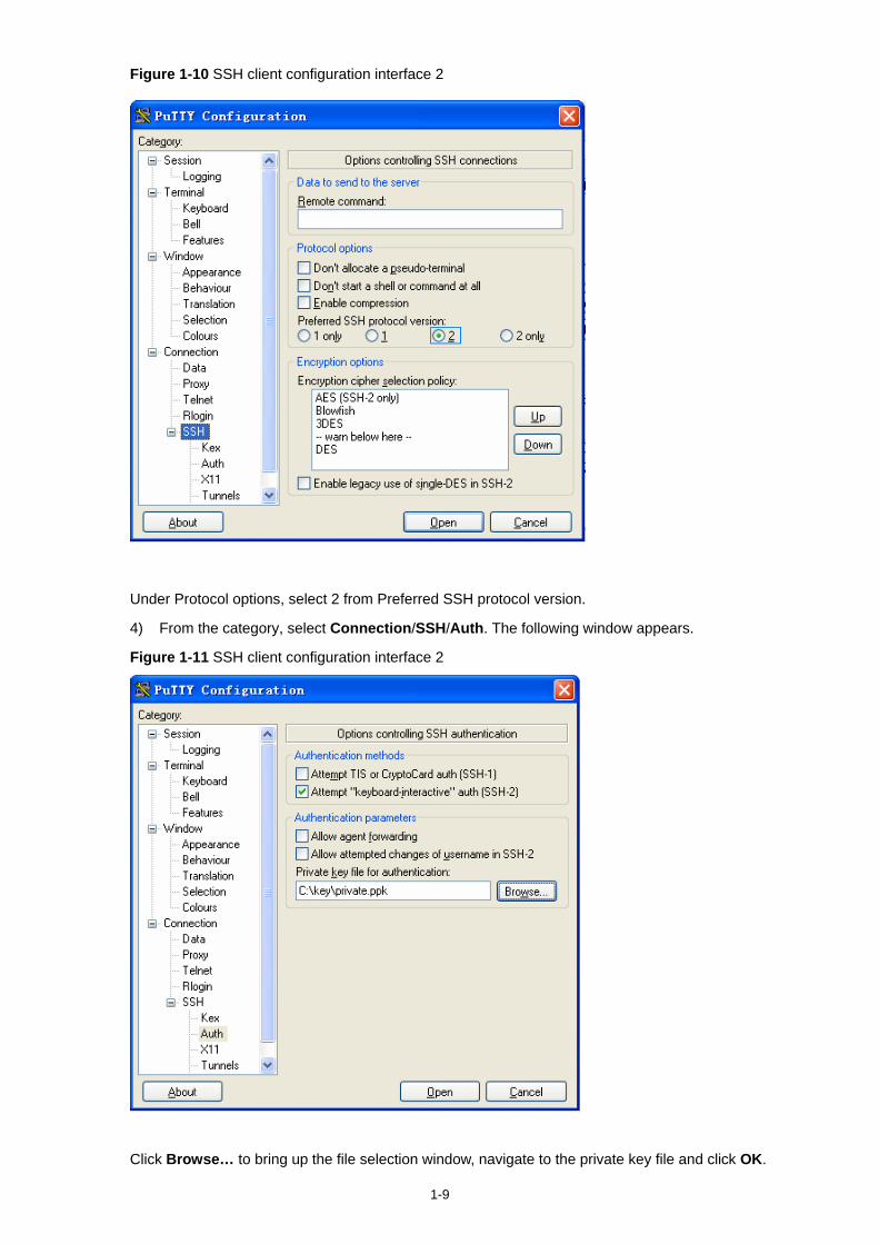
1-9
Figure 1-10 SSH client configuration interface 2
Under Protocol options, select 2 from Preferred SSH protocol version.
4) From the category, select Connection/SSH/Auth. The following window appears.
Figure 1-11 SSH client configuration interface 2
Click Browse… to bring up the file selection window, navigate to the private key file and click OK.
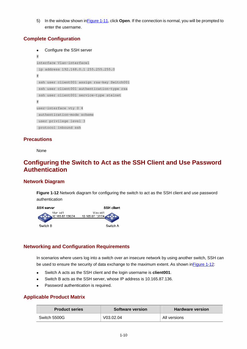
1-10
5) In the window shown inFigure 1-11, click Open. If the connection is normal, you will be prompted to enter the username.
Complete Configuration
Configure the SSH server #
interface Vlan-interface1
ip address 192.168.0.1 255.255.255.0
#
ssh user client001 assign rsa-key Switch001
ssh user client001 authentication-type rsa
ssh user client001 service-type stelnet
#
user-interface vty 0 4
authentication-mode scheme
user privilege level 3
protocol inbound ssh
Precautions
None
Configuring the Switch to Act as the SSH Client and Use Password Authentication
Network Diagram
Figure 1-12 Network diagram for configuring the switch to act as the SSH client and use password authentication
Networking and Configuration Requirements
In scenarios where users log into a switch over an insecure network by using another switch, SSH can be used to ensure the security of data exchange to the maximum extent. As shown inFigure 1-12:
Switch A acts as the SSH client and the login username is client001. Switch B acts as the SSH server, whose IP address is 10.165.87.136. Password authentication is required.
Applicable Product Matrix
Product series Software version Hardware version
Switch 5500G V03.02.04 All versions
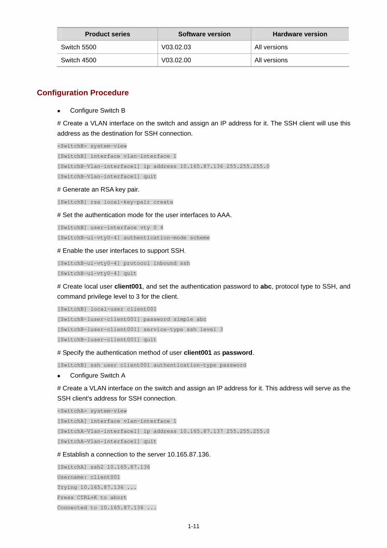
1-11
Product series Software version Hardware version
Switch 5500 V03.02.03 All versions
Switch 4500 V03.02.00 All versions
Configuration Procedure
Configure Switch B
# Create a VLAN interface on the switch and assign an IP address for it. The SSH client will use this address as the destination for SSH connection.
<SwitchB> system-view
[SwitchB] interface vlan-interface 1
[SwitchB-Vlan-interface1] ip address 10.165.87.136 255.255.255.0
[SwitchB-Vlan-interface1] quit
# Generate an RSA key pair.
[SwitchB] rsa local-key-pair create
# Set the authentication mode for the user interfaces to AAA.
[SwitchB] user-interface vty 0 4
[SwitchB-ui-vty0-4] authentication-mode scheme
# Enable the user interfaces to support SSH.
[SwitchB-ui-vty0-4] protocol inbound ssh
[SwitchB-ui-vty0-4] quit
# Create local user client001, and set the authentication password to abc, protocol type to SSH, and command privilege level to 3 for the client.
[SwitchB] local-user client001
[SwitchB-luser-client001] password simple abc
[SwitchB-luser-client001] service-type ssh level 3
[SwitchB-luser-client001] quit
# Specify the authentication method of user client001 as password.
[SwitchB] ssh user client001 authentication-type password
Configure Switch A
# Create a VLAN interface on the switch and assign an IP address for it. This address will serve as the SSH client’s address for SSH connection.
<SwitchA> system-view
[SwitchA] interface vlan-interface 1
[SwitchA-Vlan-interface1] ip address 10.165.87.137 255.255.255.0
[SwitchA-Vlan-interface1] quit
# Establish a connection to the server 10.165.87.136.
[SwitchA] ssh2 10.165.87.136
Username: client001
Trying 10.165.87.136 ...
Press CTRL+K to abort
Connected to 10.165.87.136 ...
1-12
The Server is not authenticated. Do you continue to access it?(Y/N):y
Do you want to save the server's public key?(Y/N):n
Enter password:
********************************************************************************
* Copyright(c) 2004-2008 3Com Corp. and its licensors. All rights reserved. *
* Without the owner's prior written consent, *
* no decompiling or reverse-engineering shall be allowed. *
********************************************************************************
<SwitchB>
Complete Configuration
Configure Switch B #
local-user client001
password simple abc
service-type ssh
level 3
#
interface Vlan-interface1
ip address 10.165.87.136 255.255.255.0
#
ssh user client001 authentication-type password
ssh user client001 service-type stelnet
#
user-interface vty 0 4
authentication-mode scheme
protocol inbound ssh
Configure Switch A #
interface Vlan-interface1
ip address 10.165.87.137 255.255.255.0
#
Precautions
After configuring the user interfaces to support SSH, be sure to configure the user interfaces to use AAA authentication by using the authentication-mode scheme command and configure the default domain to use the AAA method of local.
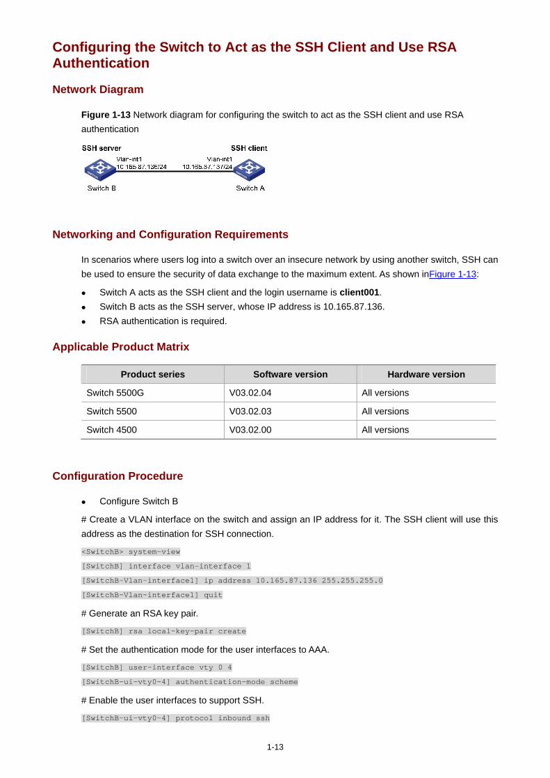
1-13
Configuring the Switch to Act as the SSH Client and Use RSA Authentication
Network Diagram
Figure 1-13 Network diagram for configuring the switch to act as the SSH client and use RSA authentication
Networking and Configuration Requirements
In scenarios where users log into a switch over an insecure network by using another switch, SSH can be used to ensure the security of data exchange to the maximum extent. As shown inFigure 1-13:
Switch A acts as the SSH client and the login username is client001. Switch B acts as the SSH server, whose IP address is 10.165.87.136. RSA authentication is required.
Applicable Product Matrix
Product series Software version Hardware version
Switch 5500G V03.02.04 All versions
Switch 5500 V03.02.03 All versions
Switch 4500 V03.02.00 All versions
Configuration Procedure
Configure Switch B
# Create a VLAN interface on the switch and assign an IP address for it. The SSH client will use this address as the destination for SSH connection.
<SwitchB> system-view
[SwitchB] interface vlan-interface 1
[SwitchB-Vlan-interface1] ip address 10.165.87.136 255.255.255.0
[SwitchB-Vlan-interface1] quit
# Generate an RSA key pair.
[SwitchB] rsa local-key-pair create
# Set the authentication mode for the user interfaces to AAA.
[SwitchB] user-interface vty 0 4
[SwitchB-ui-vty0-4] authentication-mode scheme
# Enable the user interfaces to support SSH.
[SwitchB-ui-vty0-4] protocol inbound ssh
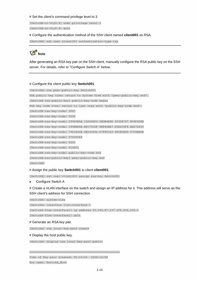
1-14
# Set the client’s command privilege level to 3.
[SwitchB-ui-vty0-4] user privilege level 3
[SwitchB-ui-vty0-4] quit
# Configure the authentication method of the SSH client named client001 as RSA.
[SwitchB] ssh user client001 authentication-type rsa
After generating an RSA key pair on the SSH client, manually configure the RSA public key on the SSH server. For details, refer to “Configure Switch A” below.
# Configure the client public key Switch001.
[SwitchB] rsa peer-public-key Switch001
RSA public key view: return to System View with "peer-public-key end".
[SwitchB-rsa-public-key] public-key-code begin
RSA key code view: return to last view with "public-key-code end".
[SwitchB-rsa-key-code] 3047
[SwitchB-rsa-key-code] 0240
[SwitchB-rsa-key-code] C8969B5A 132440F4 0BDB4E5E 40308747 804F608B
[SwitchB-rsa-key-code] 349EBD6A B0C75CDF 8B84DBE7 D5E2C4F8 AED72834
[SwitchB-rsa-key-code] 74D3404A 0B14363D D709CC63 68C8CE00 57C0EE6B
[SwitchB-rsa-key-code] 074C0CA9
[SwitchB-rsa-key-code] 0203
[SwitchB-rsa-key-code] 010001
[SwitchB-rsa-key-code] public-key-code end
[SwitchB-rsa-public-key] peer-public-key end
[SwitchB]
# Assign the public key Switch001 to client client001.
[SwitchB] ssh user client001 assign rsa-key Switch001
Configure Switch A
# Create a VLAN interface on the switch and assign an IP address for it. This address will serve as the SSH client’s address for SSH connection.
<SwitchA> system-view
[SwitchA] interface vlan-interface 1
[SwitchA-Vlan-interface1] ip address 10.165.87.137 255.255.255.0
[SwitchA-Vlan-interface1] quit
# Generate an RSA key pair.
[SwitchA] rsa local-key-pair create
# Display the host public key.
<SwitchA> display rsa local-key-pair public
=====================================================
Time of Key pair created: 05:15:04 2006/12/08
Key name: SwitchA_Host
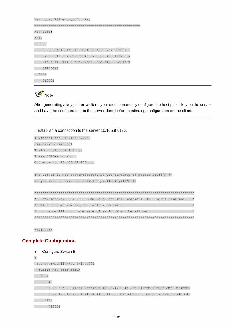
1-15
Key type: RSA encryption Key
=====================================================
Key code:
3047
0240
C8969B5A 132440F4 0BDB4E5E 40308747 804F608B
349EBD6A B0C75CDF 8B84DBE7 D5E2C4F8 AED72834
74D3404A 0B14363D D709CC63 68C8CE00 57C0EE6B
074C0CA9
0203
010001
After generating a key pair on a client, you need to manually configure the host public key on the server and have the configuration on the server done before continuing configuration on the client.
# Establish a connection to the server 10.165.87.136.
[SwitchA] ssh2 10.165.87.136
Username: client001
Trying 10.165.87.136 ...
Press CTRL+K to abort
Connected to 10.165.87.136 ...
The Server is not authenticated. Do you continue to access it?(Y/N):y
Do you want to save the server's public key?(Y/N):n
********************************************************************************
* Copyright(c) 2004-2008 3Com Corp. and its licensors. All rights reserved. *
* Without the owner's prior written consent, *
* no decompiling or reverse-engineering shall be allowed. *
********************************************************************************
<SwitchB>
Complete Configuration
Configure Switch B #
rsa peer-public-key Switch001
public-key-code begin
3047
0240
C8969B5A 132440F4 0BDB4E5E 40308747 804F608B 349EBD6A B0C75CDF 8B84DBE7
D5E2C4F8 AED72834 74D3404A 0B14363D D709CC63 68C8CE00 57C0EE6B 074C0CA9
0203
010001
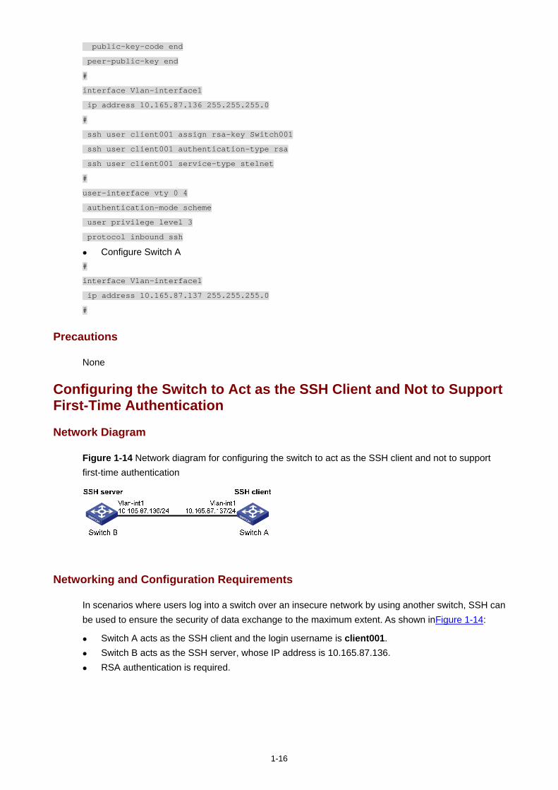
1-16
public-key-code end
peer-public-key end
#
interface Vlan-interface1
ip address 10.165.87.136 255.255.255.0
#
ssh user client001 assign rsa-key Switch001
ssh user client001 authentication-type rsa
ssh user client001 service-type stelnet
#
user-interface vty 0 4
authentication-mode scheme
user privilege level 3
protocol inbound ssh
Configure Switch A #
interface Vlan-interface1
ip address 10.165.87.137 255.255.255.0
#
Precautions
None
Configuring the Switch to Act as the SSH Client and Not to Support First-Time Authentication
Network Diagram
Figure 1-14 Network diagram for configuring the switch to act as the SSH client and not to support first-time authentication
Networking and Configuration Requirements
In scenarios where users log into a switch over an insecure network by using another switch, SSH can be used to ensure the security of data exchange to the maximum extent. As shown inFigure 1-14:
Switch A acts as the SSH client and the login username is client001. Switch B acts as the SSH server, whose IP address is 10.165.87.136. RSA authentication is required.
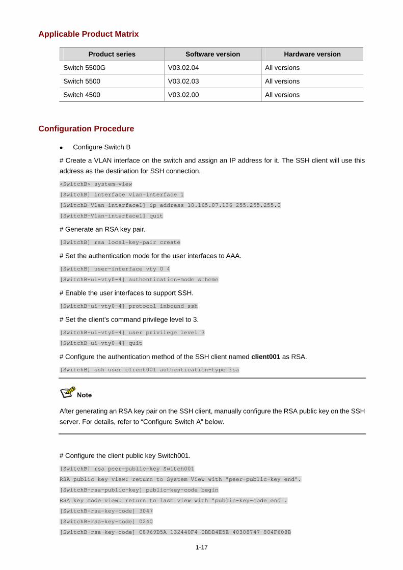
1-17
Applicable Product Matrix
Product series Software version Hardware version
Switch 5500G V03.02.04 All versions
Switch 5500 V03.02.03 All versions
Switch 4500 V03.02.00 All versions
Configuration Procedure
Configure Switch B
# Create a VLAN interface on the switch and assign an IP address for it. The SSH client will use this address as the destination for SSH connection.
<SwitchB> system-view
[SwitchB] interface vlan-interface 1
[SwitchB-Vlan-interface1] ip address 10.165.87.136 255.255.255.0
[SwitchB-Vlan-interface1] quit
# Generate an RSA key pair.
[SwitchB] rsa local-key-pair create
# Set the authentication mode for the user interfaces to AAA.
[SwitchB] user-interface vty 0 4
[SwitchB-ui-vty0-4] authentication-mode scheme
# Enable the user interfaces to support SSH.
[SwitchB-ui-vty0-4] protocol inbound ssh
# Set the client’s command privilege level to 3.
[SwitchB-ui-vty0-4] user privilege level 3
[SwitchB-ui-vty0-4] quit
# Configure the authentication method of the SSH client named client001 as RSA.
[SwitchB] ssh user client001 authentication-type rsa
After generating an RSA key pair on the SSH client, manually configure the RSA public key on the SSH server. For details, refer to “Configure Switch A” below.
# Configure the client public key Switch001.
[SwitchB] rsa peer-public-key Switch001
RSA public key view: return to System View with "peer-public-key end".
[SwitchB-rsa-public-key] public-key-code begin
RSA key code view: return to last view with "public-key-code end".
[SwitchB-rsa-key-code] 3047
[SwitchB-rsa-key-code] 0240
[SwitchB-rsa-key-code] C8969B5A 132440F4 0BDB4E5E 40308747 804F608B
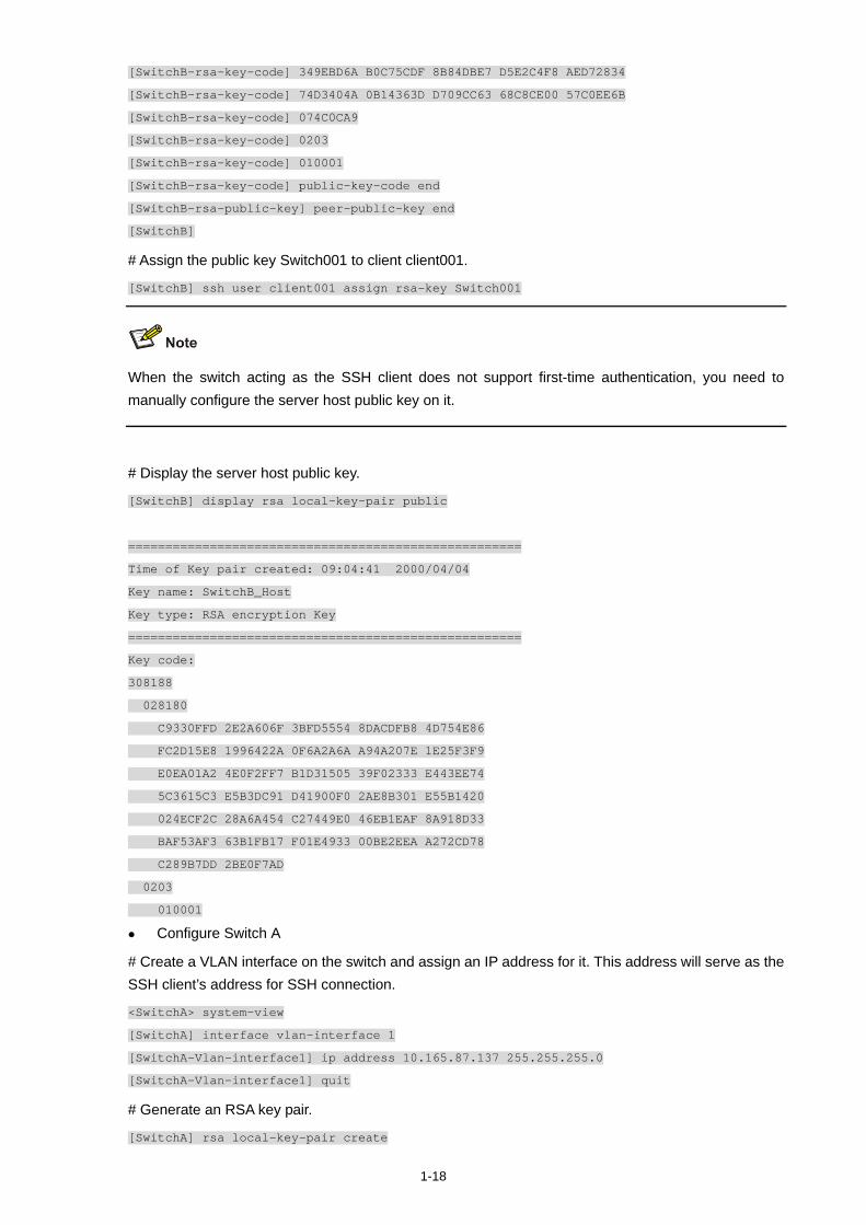
1-18
[SwitchB-rsa-key-code] 349EBD6A B0C75CDF 8B84DBE7 D5E2C4F8 AED72834
[SwitchB-rsa-key-code] 74D3404A 0B14363D D709CC63 68C8CE00 57C0EE6B
[SwitchB-rsa-key-code] 074C0CA9
[SwitchB-rsa-key-code] 0203
[SwitchB-rsa-key-code] 010001
[SwitchB-rsa-key-code] public-key-code end
[SwitchB-rsa-public-key] peer-public-key end
[SwitchB]
# Assign the public key Switch001 to client client001.
[SwitchB] ssh user client001 assign rsa-key Switch001
When the switch acting as the SSH client does not support first-time authentication, you need to manually configure the server host public key on it.
# Display the server host public key.
[SwitchB] display rsa local-key-pair public
=====================================================
Time of Key pair created: 09:04:41 2000/04/04
Key name: SwitchB_Host
Key type: RSA encryption Key
=====================================================
Key code:
308188
028180
C9330FFD 2E2A606F 3BFD5554 8DACDFB8 4D754E86
FC2D15E8 1996422A 0F6A2A6A A94A207E 1E25F3F9
E0EA01A2 4E0F2FF7 B1D31505 39F02333 E443EE74
5C3615C3 E5B3DC91 D41900F0 2AE8B301 E55B1420
024ECF2C 28A6A454 C27449E0 46EB1EAF 8A918D33
BAF53AF3 63B1FB17 F01E4933 00BE2EEA A272CD78
C289B7DD 2BE0F7AD
0203
010001
Configure Switch A
# Create a VLAN interface on the switch and assign an IP address for it. This address will serve as the SSH client’s address for SSH connection.
<SwitchA> system-view
[SwitchA] interface vlan-interface 1
[SwitchA-Vlan-interface1] ip address 10.165.87.137 255.255.255.0
[SwitchA-Vlan-interface1] quit
# Generate an RSA key pair.
[SwitchA] rsa local-key-pair create
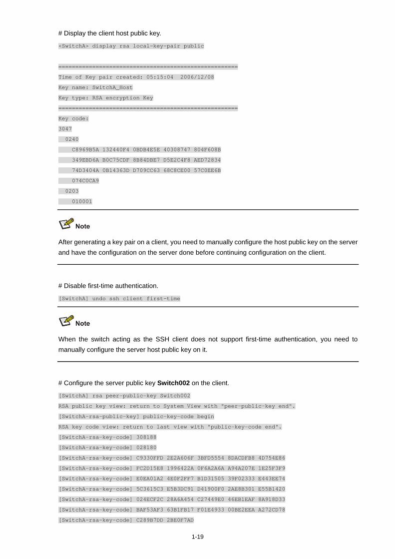
1-19
# Display the client host public key.
<SwitchA> display rsa local-key-pair public
=====================================================
Time of Key pair created: 05:15:04 2006/12/08
Key name: SwitchA_Host
Key type: RSA encryption Key
=====================================================
Key code:
3047
0240
C8969B5A 132440F4 0BDB4E5E 40308747 804F608B
349EBD6A B0C75CDF 8B84DBE7 D5E2C4F8 AED72834
74D3404A 0B14363D D709CC63 68C8CE00 57C0EE6B
074C0CA9
0203
010001
After generating a key pair on a client, you need to manually configure the host public key on the server and have the configuration on the server done before continuing configuration on the client.
# Disable first-time authentication.
[SwitchA] undo ssh client first-time
When the switch acting as the SSH client does not support first-time authentication, you need to manually configure the server host public key on it.
# Configure the server public key Switch002 on the client.
[SwitchA] rsa peer-public-key Switch002
RSA public key view: return to System View with "peer-public-key end".
[SwitchA-rsa-public-key] public-key-code begin
RSA key code view: return to last view with "public-key-code end".
[SwitchA-rsa-key-code] 308188
[SwitchA-rsa-key-code] 028180
[SwitchA-rsa-key-code] C9330FFD 2E2A606F 3BFD5554 8DACDFB8 4D754E86
[SwitchA-rsa-key-code] FC2D15E8 1996422A 0F6A2A6A A94A207E 1E25F3F9
[SwitchA-rsa-key-code] E0EA01A2 4E0F2FF7 B1D31505 39F02333 E443EE74
[SwitchA-rsa-key-code] 5C3615C3 E5B3DC91 D41900F0 2AE8B301 E55B1420
[SwitchA-rsa-key-code] 024ECF2C 28A6A454 C27449E0 46EB1EAF 8A918D33
[SwitchA-rsa-key-code] BAF53AF3 63B1FB17 F01E4933 00BE2EEA A272CD78
[SwitchA-rsa-key-code] C289B7DD 2BE0F7AD
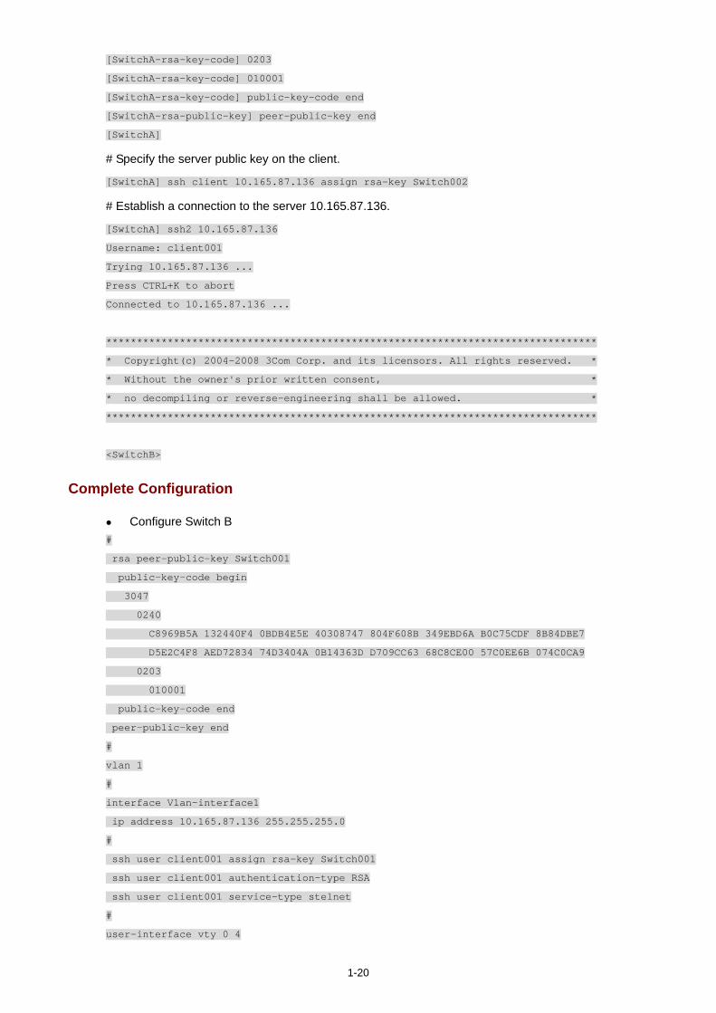
1-20
[SwitchA-rsa-key-code] 0203
[SwitchA-rsa-key-code] 010001
[SwitchA-rsa-key-code] public-key-code end
[SwitchA-rsa-public-key] peer-public-key end
[SwitchA]
# Specify the server public key on the client.
[SwitchA] ssh client 10.165.87.136 assign rsa-key Switch002
# Establish a connection to the server 10.165.87.136.
[SwitchA] ssh2 10.165.87.136
Username: client001
Trying 10.165.87.136 ...
Press CTRL+K to abort
Connected to 10.165.87.136 ...
********************************************************************************
* Copyright(c) 2004-2008 3Com Corp. and its licensors. All rights reserved. *
* Without the owner's prior written consent, *
* no decompiling or reverse-engineering shall be allowed. *
********************************************************************************
<SwitchB>
Complete Configuration
Configure Switch B #
rsa peer-public-key Switch001
public-key-code begin
3047
0240
C8969B5A 132440F4 0BDB4E5E 40308747 804F608B 349EBD6A B0C75CDF 8B84DBE7
D5E2C4F8 AED72834 74D3404A 0B14363D D709CC63 68C8CE00 57C0EE6B 074C0CA9
0203
010001
public-key-code end
peer-public-key end
#
vlan 1
#
interface Vlan-interface1
ip address 10.165.87.136 255.255.255.0
#
ssh user client001 assign rsa-key Switch001
ssh user client001 authentication-type RSA
ssh user client001 service-type stelnet
#
user-interface vty 0 4
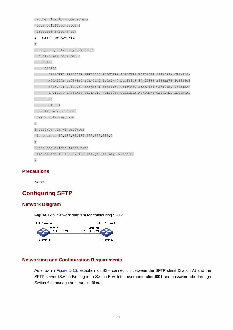
1-21
authentication-mode scheme
user privilege level 3
protocol inbound ssh
Configure Switch A #
rsa peer-public-key Switch002
public-key-code begin
308188
028180
C9330FFD 2E2A606F 3BFD5554 8DACDFB8 4D754E86 FC2D15E8 1996422A 0F6A2A6A
A94A207E 1E25F3F9 E0EA01A2 4E0F2FF7 B1D31505 39F02333 E443EE74 5C3615C3
E5B3DC91 D41900F0 2AE8B301 E55B1420 024ECF2C 28A6A454 C27449E0 46EB1EAF
8A918D33 BAF53AF3 63B1FB17 F01E4933 00BE2EEA A272CD78 C289B7DD 2BE0F7AD
0203
010001
public-key-code end
peer-public-key end
#
interface Vlan-interface1
ip address 10.165.87.137 255.255.255.0
#
undo ssh client first-time
ssh client 10.165.87.136 assign rsa-key Switch002
#
Precautions
None
Configuring SFTP
Network Diagram
Figure 1-15 Network diagram for configuring SFTP
Networking and Configuration Requirements
As shown inFigure 1-15, establish an SSH connection between the SFTP client (Switch A) and the SFTP server (Switch B). Log in to Switch B with the username client001 and password abc through Switch A to manage and transfer files.
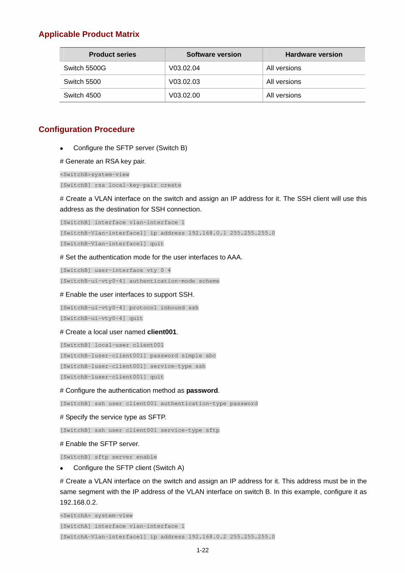
1-22
Applicable Product Matrix
Product series Software version Hardware version
Switch 5500G V03.02.04 All versions
Switch 5500 V03.02.03 All versions
Switch 4500 V03.02.00 All versions
Configuration Procedure
Configure the SFTP server (Switch B)
# Generate an RSA key pair.
<SwitchB>system-view
[SwitchB] rsa local-key-pair create
# Create a VLAN interface on the switch and assign an IP address for it. The SSH client will use this address as the destination for SSH connection.
[SwitchB] interface vlan-interface 1
[SwitchB-Vlan-interface1] ip address 192.168.0.1 255.255.255.0
[SwitchB-Vlan-interface1] quit
# Set the authentication mode for the user interfaces to AAA.
[SwitchB] user-interface vty 0 4
[SwitchB-ui-vty0-4] authentication-mode scheme
# Enable the user interfaces to support SSH.
[SwitchB-ui-vty0-4] protocol inbound ssh
[SwitchB-ui-vty0-4] quit
# Create a local user named client001.
[SwitchB] local-user client001
[SwitchB-luser-client001] password simple abc
[SwitchB-luser-client001] service-type ssh
[SwitchB-luser-client001] quit
# Configure the authentication method as password.
[SwitchB] ssh user client001 authentication-type password
# Specify the service type as SFTP.
[SwitchB] ssh user client001 service-type sftp
# Enable the SFTP server.
[SwitchB] sftp server enable
Configure the SFTP client (Switch A)
# Create a VLAN interface on the switch and assign an IP address for it. This address must be in the same segment with the IP address of the VLAN interface on switch B. In this example, configure it as 192.168.0.2.
<SwitchA> system-view
[SwitchA] interface vlan-interface 1
[SwitchA-Vlan-interface1] ip address 192.168.0.2 255.255.255.0

1-23
[SwitchA-Vlan-interface1] quit
# Connect to the remote SFTP server using the username client001 and password abc to enter SFTP client view.
[SwitchA] sftp 192.168.0.1
Input Username: client001
Trying 192.168.0.1 ...
Press CTRL+K to abort
Connected to 192.168.0.1 ...
The Server is not authenticated. Do you continue access it? [Y/N]:y
Do you want to save the server's public key? [Y/N]:n
Enter password:
sftp-client>
# Display the current directory of the server, delete the file z and verify the deletion.
sftp-client> dir
-rwxrwxrwx 1 noone nogroup 1759 Aug 23 06:52 config.cfg
-rwxrwxrwx 1 noone nogroup 225 Aug 24 08:01 pubkey2
-rwxrwxrwx 1 noone nogroup 283 Aug 24 07:39 pubkey1
drwxrwxrwx 1 noone nogroup 0 Sep 01 06:22 new
-rwxrwxrwx 1 noone nogroup 225 Sep 01 06:55 pub
-rwxrwxrwx 1 noone nogroup 0 Sep 01 08:00 z
sftp-client> delete z
The following files will be deleted:
flash:/z
Are you sure to delete it?(Y/N):y
This operation may take a long time.Please wait...
File successfully Removed
sftp-client> dir
-rwxrwxrwx 1 noone nogroup 1759 Aug 23 06:52 config.cfg
-rwxrwxrwx 1 noone nogroup 225 Aug 24 08:01 pubkey2
-rwxrwxrwx 1 noone nogroup 283 Aug 24 07:39 pubkey1
drwxrwxrwx 1 noone nogroup 0 Sep 01 06:22 new
-rwxrwxrwx 1 noone nogroup 225 Sep 01 06:55 pub
# Add a directory named new1, and then check that the new directory has been successfully created.
sftp-client> mkdir new1
New directory created
sftp-client> dir
-rwxrwxrwx 1 noone nogroup 1759 Aug 23 06:52 config.cfg
-rwxrwxrwx 1 noone nogroup 225 Aug 24 08:01 pubkey2
-rwxrwxrwx 1 noone nogroup 283 Aug 24 07:39 pubkey1
drwxrwxrwx 1 noone nogroup 0 Sep 01 06:22 new
-rwxrwxrwx 1 noone nogroup 225 Sep 01 06:55 pub
drwxrwxrwx 1 noone nogroup 0 Sep 02 06:30 new1
# Rename the directory to new2, and then verify the operation.
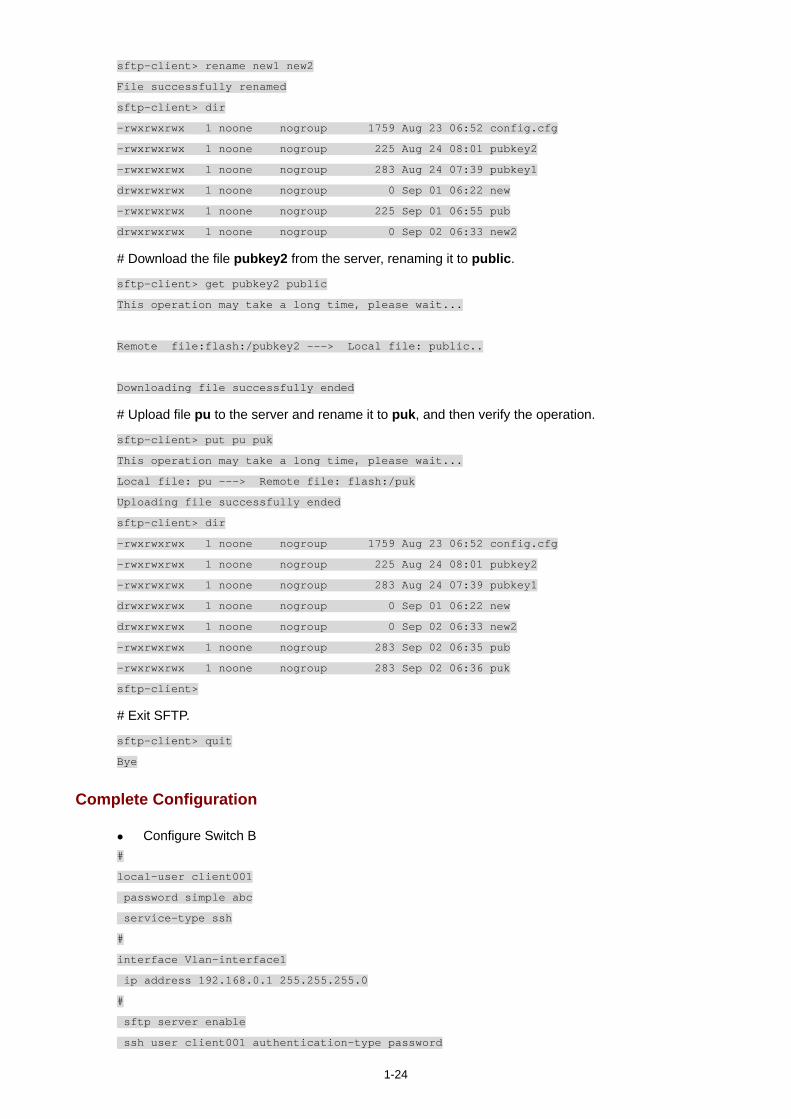
1-24
sftp-client> rename new1 new2
File successfully renamed
sftp-client> dir
-rwxrwxrwx 1 noone nogroup 1759 Aug 23 06:52 config.cfg
-rwxrwxrwx 1 noone nogroup 225 Aug 24 08:01 pubkey2
-rwxrwxrwx 1 noone nogroup 283 Aug 24 07:39 pubkey1
drwxrwxrwx 1 noone nogroup 0 Sep 01 06:22 new
-rwxrwxrwx 1 noone nogroup 225 Sep 01 06:55 pub
drwxrwxrwx 1 noone nogroup 0 Sep 02 06:33 new2
# Download the file pubkey2 from the server, renaming it to public.
sftp-client> get pubkey2 public
This operation may take a long time, please wait...
Remote file:flash:/pubkey2 ---> Local file: public..
Downloading file successfully ended
# Upload file pu to the server and rename it to puk, and then verify the operation.
sftp-client> put pu puk
This operation may take a long time, please wait...
Local file: pu ---> Remote file: flash:/puk
Uploading file successfully ended
sftp-client> dir
-rwxrwxrwx 1 noone nogroup 1759 Aug 23 06:52 config.cfg
-rwxrwxrwx 1 noone nogroup 225 Aug 24 08:01 pubkey2
-rwxrwxrwx 1 noone nogroup 283 Aug 24 07:39 pubkey1
drwxrwxrwx 1 noone nogroup 0 Sep 01 06:22 new
drwxrwxrwx 1 noone nogroup 0 Sep 02 06:33 new2
-rwxrwxrwx 1 noone nogroup 283 Sep 02 06:35 pub
-rwxrwxrwx 1 noone nogroup 283 Sep 02 06:36 puk
sftp-client>
# Exit SFTP.
sftp-client> quit
Bye
Complete Configuration
Configure Switch B #
local-user client001
password simple abc
service-type ssh
#
interface Vlan-interface1
ip address 192.168.0.1 255.255.255.0
#
sftp server enable
ssh user client001 authentication-type password
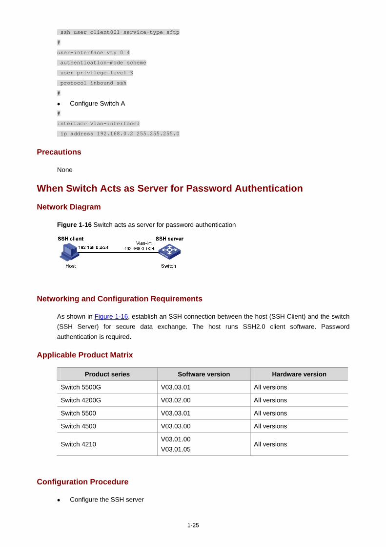
1-25
ssh user client001 service-type sftp
#
user-interface vty 0 4
authentication-mode scheme
user privilege level 3
protocol inbound ssh
#
Configure Switch A #
interface Vlan-interface1
ip address 192.168.0.2 255.255.255.0
Precautions
None
When Switch Acts as Server for Password Authentication
Network Diagram
Figure 1-16 Switch acts as server for password authentication
Networking and Configuration Requirements
As shown in Figure 1-16, establish an SSH connection between the host (SSH Client) and the switch (SSH Server) for secure data exchange. The host runs SSH2.0 client software. Password authentication is required.
Applicable Product Matrix
Product series Software version Hardware version
Switch 5500G V03.03.01 All versions
Switch 4200G V03.02.00 All versions
Switch 5500 V03.03.01 All versions
Switch 4500 V03.03.00 All versions
Switch 4210 V03.01.00 V03.01.05
All versions
Configuration Procedure
Configure the SSH server
1-26
# Create a VLAN interface on the switch and assign an IP address, which the SSH client will use as the destination for SSH connection.
<Switch> system-view
[Switch] interface vlan-interface 1
[Switch-Vlan-interface1] ip address 192.168.0.1 255.255.255.0
[Switch-Vlan-interface1] quit
Generating the RSA and DSA key pairs on the server is prerequisite to SSH login. The 4500 switch supports RSA key pair only. When the 4500 serves as a server, it can generate
RSA key pair only.
# Generate RSA and DSA key pairs.
[Switch] public-key local create rsa
[Switch] public-key local create dsa
# Set the authentication mode for the user interfaces to AAA.
[Switch] user-interface vty 0 4
[Switch-ui-vty0-4] authentication-mode scheme
# Enable the user interfaces to support SSH.
[Switch-ui-vty0-4] protocol inbound ssh
[Switch-ui-vty0-4] quit
# Create local client client001, and set the authentication password to abc, protocol type to SSH, and command privilege level to 3 for the client.
[Switch] local-user client001
[Switch-luser-client001] password simple abc
[Switch-luser-client001] service-type ssh level 3
[Switch-luser-client001] quit
# Specify the authentication method of user client001 as password.
[Switch] ssh user client001 authentication-type password
Configure the SSH client
# Configure an IP address (192.168.0.2 in this case) for the SSH client. This IP address and that of the VLAN interface on the switch must be in the same network segment.
# Configure the SSH client software to establish a connection to the SSH server.
Take SSH client software Putty (version 0.58) as an example:
1) Run PuTTY.exe to enter the following configuration interface.

1-27
Figure 1-17 SSH client configuration interface
In the Host Name (or IP address) text box, enter the IP address of the SSH server.
2) From the category on the left pane of the window, select SSH under Connection. The window as shown in Figure 1-18 appears.
Figure 1-18 SSH client configuration interface 2
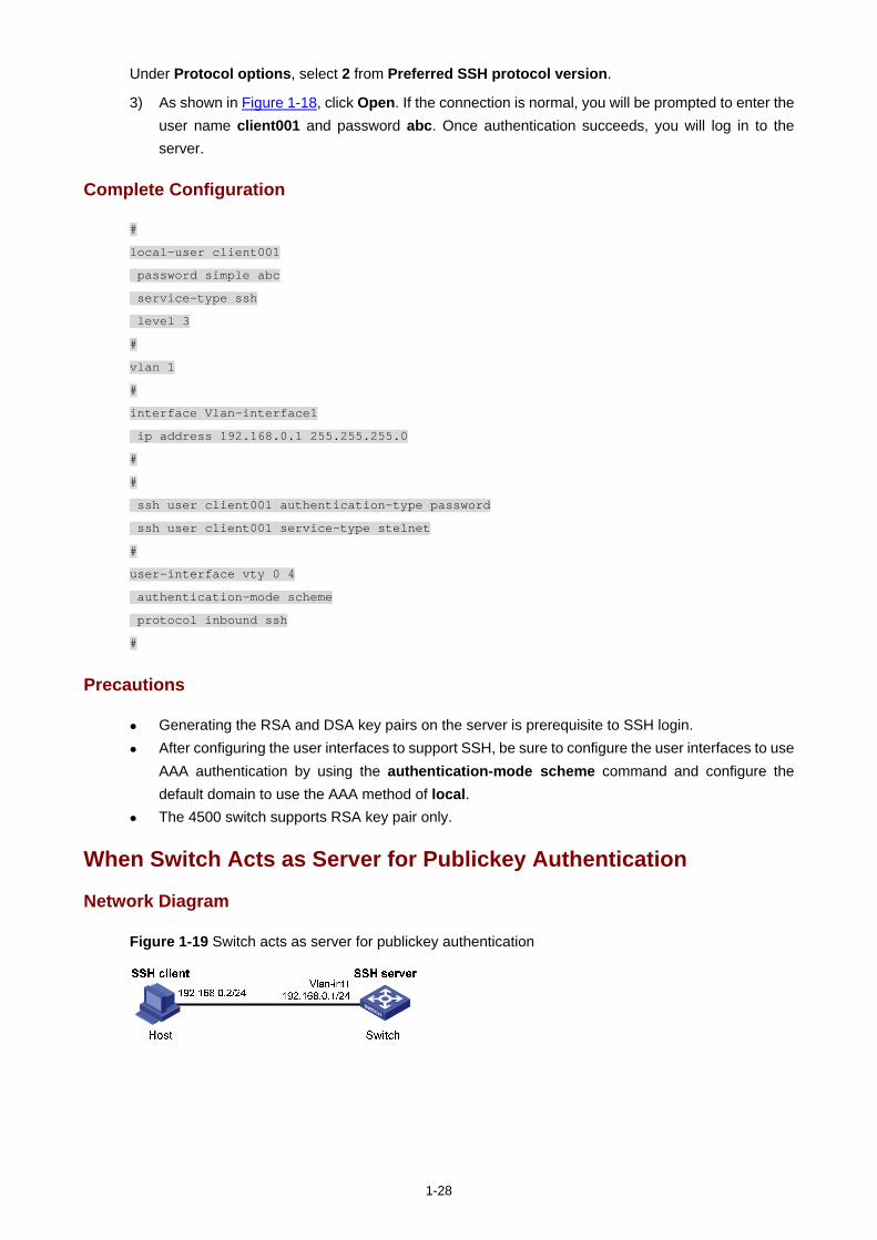
1-28
Under Protocol options, select 2 from Preferred SSH protocol version.
3) As shown in Figure 1-18, click Open. If the connection is normal, you will be prompted to enter the user name client001 and password abc. Once authentication succeeds, you will log in to the server.
Complete Configuration
#
local-user client001
password simple abc
service-type ssh
level 3
#
vlan 1
#
interface Vlan-interface1
ip address 192.168.0.1 255.255.255.0
#
#
ssh user client001 authentication-type password
ssh user client001 service-type stelnet
#
user-interface vty 0 4
authentication-mode scheme
protocol inbound ssh
#
Precautions
Generating the RSA and DSA key pairs on the server is prerequisite to SSH login. After configuring the user interfaces to support SSH, be sure to configure the user interfaces to use
AAA authentication by using the authentication-mode scheme command and configure the default domain to use the AAA method of local.
The 4500 switch supports RSA key pair only.
When Switch Acts as Server for Publickey Authentication
Network Diagram
Figure 1-19 Switch acts as server for publickey authentication
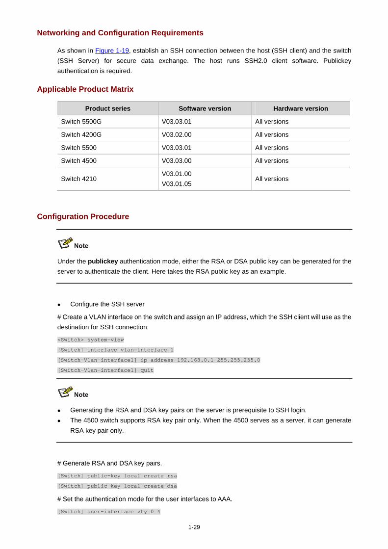
1-29
Networking and Configuration Requirements
As shown in Figure 1-19, establish an SSH connection between the host (SSH client) and the switch (SSH Server) for secure data exchange. The host runs SSH2.0 client software. Publickey authentication is required.
Applicable Product Matrix
Product series Software version Hardware version
Switch 5500G V03.03.01 All versions
Switch 4200G V03.02.00 All versions
Switch 5500 V03.03.01 All versions
Switch 4500 V03.03.00 All versions
Switch 4210 V03.01.00 V03.01.05
All versions
Configuration Procedure
Under the publickey authentication mode, either the RSA or DSA public key can be generated for the server to authenticate the client. Here takes the RSA public key as an example.
Configure the SSH server
# Create a VLAN interface on the switch and assign an IP address, which the SSH client will use as the destination for SSH connection.
<Switch> system-view
[Switch] interface vlan-interface 1
[Switch-Vlan-interface1] ip address 192.168.0.1 255.255.255.0
[Switch-Vlan-interface1] quit
Generating the RSA and DSA key pairs on the server is prerequisite to SSH login. The 4500 switch supports RSA key pair only. When the 4500 serves as a server, it can generate
RSA key pair only.
# Generate RSA and DSA key pairs.
[Switch] public-key local create rsa
[Switch] public-key local create dsa
# Set the authentication mode for the user interfaces to AAA.
[Switch] user-interface vty 0 4
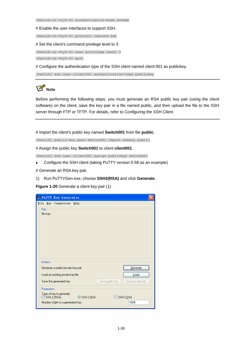
1-30
[Switch-ui-vty0-4] authentication-mode scheme
# Enable the user interfaces to support SSH.
[Switch-ui-vty0-4] protocol inbound ssh
# Set the client’s command privilege level to 3
[Switch-ui-vty0-4] user privilege level 3
[Switch-ui-vty0-4] quit
# Configure the authentication type of the SSH client named client 001 as publickey.
[Switch] ssh user client001 authentication-type publickey
Before performing the following steps, you must generate an RSA public key pair (using the client software) on the client, save the key pair in a file named public, and then upload the file to the SSH server through FTP or TFTP. For details, refer to Configuring the SSH Client.
# Import the client’s public key named Switch001 from file public.
[Switch] public-key peer Switch001 import sshkey public
# Assign the public key Switch001 to client client001.
[Switch] ssh user client001 assign publickey Switch001
Configure the SSH client (taking PuTTY version 0.58 as an example)
# Generate an RSA key pair.
1) Run PuTTYGen.exe, choose SSH2(RSA) and click Generate.
Figure 1-20 Generate a client key pair (1)
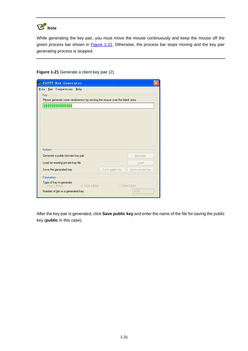
1-31
While generating the key pair, you must move the mouse continuously and keep the mouse off the green process bar shown in Figure 1-21. Otherwise, the process bar stops moving and the key pair generating process is stopped.
Figure 1-21 Generate a client key pair (2)
After the key pair is generated, click Save public key and enter the name of the file for saving the public key (public in this case).
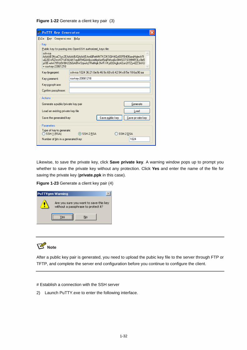
1-32
Figure 1-22 Generate a client key pair (3)
Likewise, to save the private key, click Save private key. A warning window pops up to prompt you whether to save the private key without any protection. Click Yes and enter the name of the file for saving the private key (private.ppk in this case).
Figure 1-23 Generate a client key pair (4)
After a public key pair is generated, you need to upload the pubic key file to the server through FTP or TFTP, and complete the server end configuration before you continue to configure the client.
# Establish a connection with the SSH server
2) Launch PuTTY.exe to enter the following interface.
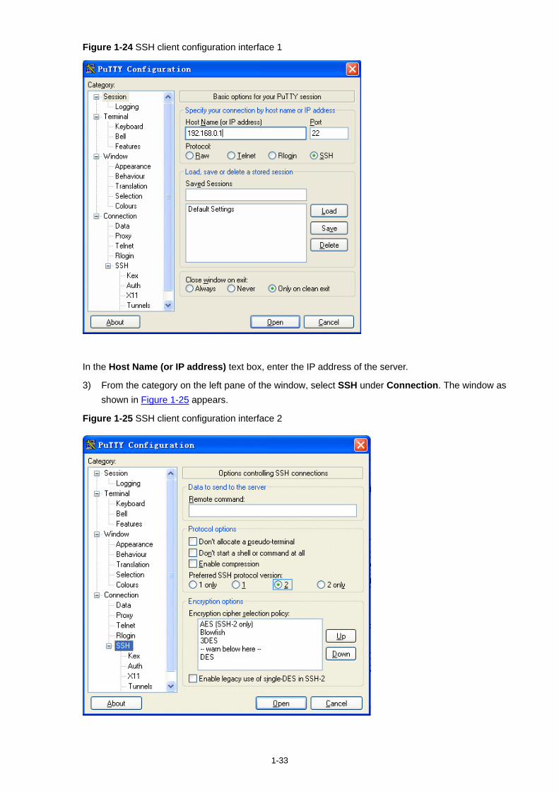
1-33
Figure 1-24 SSH client configuration interface 1
In the Host Name (or IP address) text box, enter the IP address of the server.
3) From the category on the left pane of the window, select SSH under Connection. The window as shown in Figure 1-25 appears.
Figure 1-25 SSH client configuration interface 2
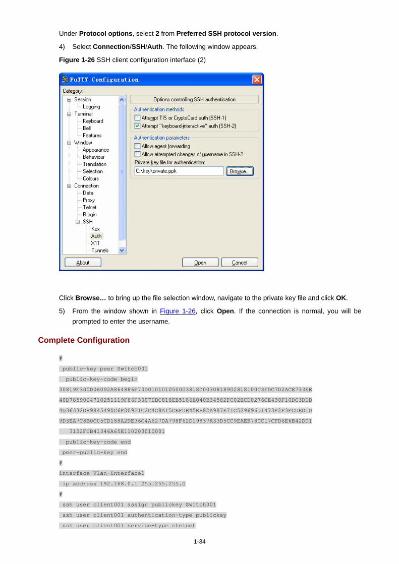
1-34
Under Protocol options, select 2 from Preferred SSH protocol version.
4) Select Connection/SSH/Auth. The following window appears.
Figure 1-26 SSH client configuration interface (2)
Click Browse… to bring up the file selection window, navigate to the private key file and click OK.
5) From the window shown in Figure 1-26, click Open. If the connection is normal, you will be prompted to enter the username.
Complete Configuration
#
public-key peer Switch001
public-key-code begin
30819F300D06092A864886F70D010101050003818D0030818902818100C3FDC7D2ACE733EE
40D78590C4710251119F86F3007EBC818EB5186E040B34582FC02ECD0276CE430F10DC3DDB
4D36332DB9845490C6F00921C2C4C8A15CEFDE45EB82A987E71C529696D1473F2F3FCDED1D
9D3EA7C8B0C05CD188A2DE36C4A627DA798F62D19837A33D5CC9EAEB78CC17CFD6E6B42DD1
3122FCB41346A65E110203010001
public-key-code end
peer-public-key end
#
interface Vlan-interface1
ip address 192.168.0.1 255.255.255.0
#
ssh user client001 assign publickey Switch001
ssh user client001 authentication-type publickey
ssh user client001 service-type stelnet
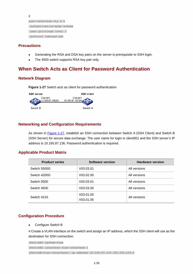
1-35
#
user-interface vty 0 4
authentication-mode scheme
user privilege level 3
protocol inbound ssh
Precautions
Generating the RSA and DSA key pairs on the server is prerequisite to SSH login. The 4500 switch supports RSA key pair only.
When Switch Acts as Client for Password Authentication
Network Diagram
Figure 1-27 Switch acts as client for password authentication
Networking and Configuration Requirements
As shown in Figure 1-27, establish an SSH connection between Switch A (SSH Client) and Switch B (SSH Server) for secure data exchange. The user name for login is client001 and the SSH server’s IP address is 10.165.87.136. Password authentication is required.
Applicable Product Matrix
Product series Software version Hardware version
Switch 5500G V03.03.01 All versions
Switch 4200G V03.02.00 All versions
Switch 5500 V03.03.01 All versions
Switch 4500 V03.03.00 All versions
Switch 4210 V03.01.00 V03.01.05
All versions
Configuration Procedure
Configure Switch B
# Create a VLAN interface on the switch and assign an IP address, which the SSH client will use as the destination for SSH connection.
<SwitchB> system-view
[SwitchB] interface vlan-interface 1
[SwitchB-Vlan-interface1] ip address 10.165.87.136 255.255.255.0

1-36
[SwitchB-Vlan-interface1] quit
Generating the RSA and DSA key pairs on the server is prerequisite to SSH login. The 4500 switch supports RSA key pair only. When the 4500 serves as a server, it can generate
RSA key pair only.
# Generate RSA and DSA key pairs.
[SwitchB] public-key local create rsa
[SwitchB] public-key local create dsa
# Set the authentication mode for the user interfaces to AAA.
[SwitchB] user-interface vty 0 4
[SwitchB-ui-vty0-4] authentication-mode scheme
# Enable the user interfaces to support SSH.
[SwitchB-ui-vty0-4] protocol inbound ssh
[SwitchB-ui-vty0-4] quit
# Create local user client001, and set the authentication password to abc, the login protocol to SSH, and user command privilege level to 3.
[SwitchB] local-user client001
[SwitchB-luser-client001] password simple abc
[SwitchB-luser-client001] service-type ssh level 3
[SwitchB-luser-client001] quit
# Configure the authentication type of user client001 as password.
[SwitchB] ssh user client001 authentication-type password
Configure Switch A
# Create a VLAN interface on the switch and assign an IP address, which serves as the SSH client’s address in an SSH connection.
<SwitchA> system-view
[SwitchA] interface vlan-interface 1
[SwitchA-Vlan-interface1] ip address 10.165.87.137 255.255.255.0
[SwitchA-Vlan-interface1] quit
# Establish a connection to the server 10.165.87.136.
[SwitchA] ssh2 10.165.87.136
Username: client001
Trying 10.165.87.136 ...
Press CTRL+K to abort
Connected to 10.165.87.136 ...
The Server is not authenticated. Do you continue to access it?(Y/N):y
Do you want to save the server's public key?(Y/N):n
Enter password:
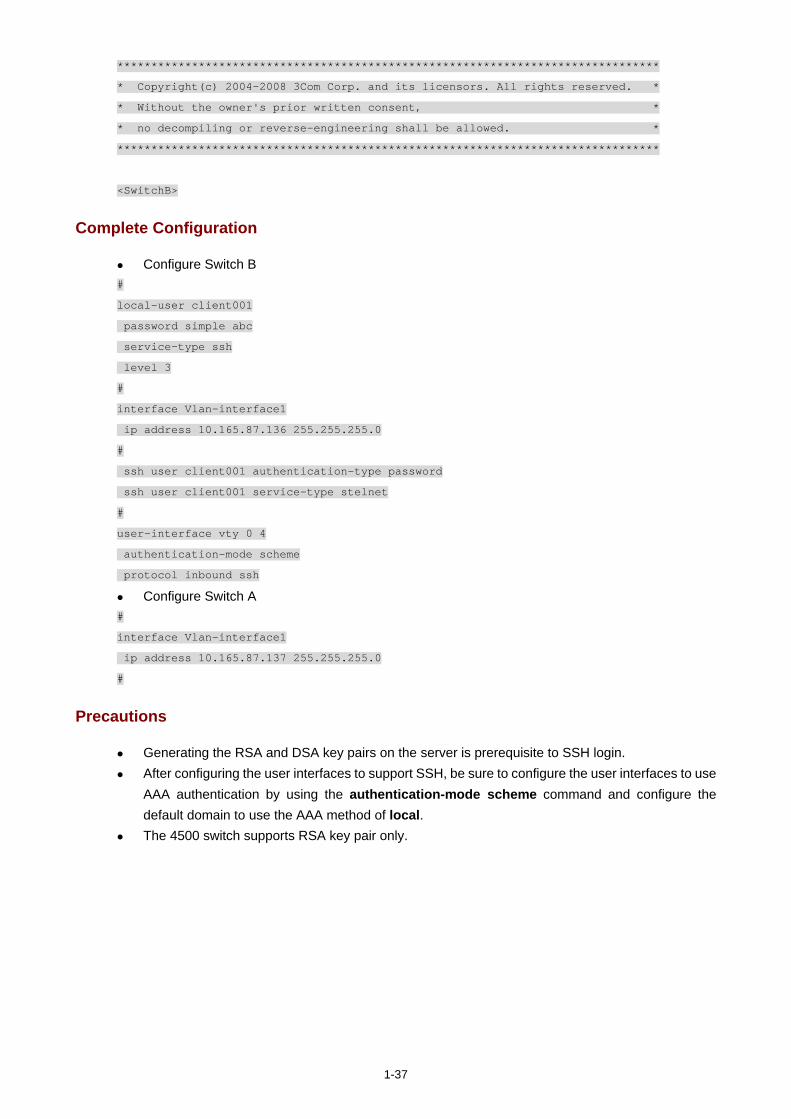
1-37
********************************************************************************
* Copyright(c) 2004-2008 3Com Corp. and its licensors. All rights reserved. *
* Without the owner's prior written consent, *
* no decompiling or reverse-engineering shall be allowed. *
********************************************************************************
<SwitchB>
Complete Configuration
Configure Switch B #
local-user client001
password simple abc
service-type ssh
level 3
#
interface Vlan-interface1
ip address 10.165.87.136 255.255.255.0
#
ssh user client001 authentication-type password
ssh user client001 service-type stelnet
#
user-interface vty 0 4
authentication-mode scheme
protocol inbound ssh
Configure Switch A #
interface Vlan-interface1
ip address 10.165.87.137 255.255.255.0
#
Precautions
Generating the RSA and DSA key pairs on the server is prerequisite to SSH login. After configuring the user interfaces to support SSH, be sure to configure the user interfaces to use
AAA authentication by using the authentication-mode scheme command and configure the default domain to use the AAA method of local.
The 4500 switch supports RSA key pair only.
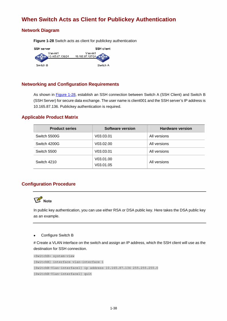
1-38
When Switch Acts as Client for Publickey Authentication
Network Diagram
Figure 1-28 Switch acts as client for publickey authentication
Networking and Configuration Requirements
As shown in Figure 1-28, establish an SSH connection between Switch A (SSH Client) and Switch B (SSH Server) for secure data exchange. The user name is client001 and the SSH server’s IP address is 10.165.87.136. Publickey authentication is required.
Applicable Product Matrix
Product series Software version Hardware version
Switch 5500G V03.03.01 All versions
Switch 4200G V03.02.00 All versions
Switch 5500 V03.03.01 All versions
Switch 4210 V03.01.00 V03.01.05
All versions
Configuration Procedure
In public key authentication, you can use either RSA or DSA public key. Here takes the DSA public key as an example.
Configure Switch B
# Create a VLAN interface on the switch and assign an IP address, which the SSH client will use as the destination for SSH connection.
<SwitchB> system-view
[SwitchB] interface vlan-interface 1
[SwitchB-Vlan-interface1] ip address 10.165.87.136 255.255.255.0
[SwitchB-Vlan-interface1] quit
1-39
Generating the RSA and DSA key pairs on the server is prerequisite to SSH login.
# Generate RSA and DSA key pairs.
[SwitchB] public-key local create rsa
[SwitchB] public-key local create dsa
# Set the authentication mode for the user interfaces to AAA.
[SwitchB] user-interface vty 0 4
[SwitchB-ui-vty0-4] authentication-mode scheme
# Enable the user interfaces to support SSH.
[SwitchB-ui-vty0-4] protocol inbound ssh
# Set the user command privilege level to 3.
[SwitchB-ui-vty0-4] user privilege level 3
[SwitchB-ui-vty0-4] quit
# Specify the authentication type of user client001 as publickey.
[SwitchB] ssh user client001 authentication-type publickey
Before doing the following steps, you must first generate a DSA public key pair on the client and save the key pair in a file named Switch001, and then upload the file to the SSH server through FTP or TFTP. For details, refer to “Configure Switch A”.
# Import the client public key pair named Switch001 from the file Switch001.
[SwitchB] public-key peer Switch001 import sshkey Switch001
# Assign the public key Switch001 to user client001.
[SwitchB] ssh user client001 assign publickey Switch001
Configure Switch A
# Create a VLAN interface on the switch and assign an IP address, which serves as the SSH client’s address in an SSH connection.
<SwitchA> system-view
[SwitchA] interface vlan-interface 1
[SwitchA-Vlan-interface1] ip address 10.165.87.137 255.255.255.0
[SwitchA-Vlan-interface1] quit
# Generate a DSA key pair
[SwitchA] public-key local create dsa
# Export the generated DSA key pair to a file named Switch001.
[SwitchA] public-key local export dsa ssh2 Switch001
1-40
After the key pair is generated, you need to upload the pubic key file to the server through FTP or TFTP and complete the server end configuration before you continue to configure the client.
# Establish an SSH connection to the server 10.165.87.136.
[SwitchA] ssh2 10.165.87.136 identity-key dsa
Username: client001
Trying 10.165.87.136 ...
Press CTRL+K to abort
Connected to 10.165.87.136 ...
The Server is not authenticated. Do you continue to access it?(Y/N):y
Do you want to save the server's public key?(Y/N):n
********************************************************************************
* Copyright(c) 2004-2008 3Com Corp. and its licensors. All rights reserved. *
* Without the owner's prior written consent, *
* no decompiling or reverse-engineering shall be allowed. *
********************************************************************************
<SwitchB>
Complete Configuration
Configure Switch B #
public-key peer Switch001
public-key-code begin
308201B73082012C06072A8648CE3804013082011F02818100D757262C4584C44C211F18BD
96E5F061C4F0A423F7FE6B6B85B34CEF72CE14A0D3A5222FE08CECE65BE6C265854889DC1E
DBD13EC8B274DA9F75BA26CCB987723602787E922BA84421F22C3C89CB9B06FD60FE01941D
DD77FE6B12893DA76EEBC1D128D97F0678D7722B5341C8506F358214B16A2FAC4B36895038
7811C7DA33021500C773218C737EC8EE993B4F2DED30F48EDACE915F0281810082269009E1
4EC474BAF2932E69D3B1F18517AD9594184CCDFCEAE96EC4D5EF93133E84B47093C52B20CD
35D02492B3959EC6499625BC4FA5082E22C5B374E16DD00132CE71B020217091AC717B6123
91C76C1FB2E88317C1BD8171D41ECB83E210C03CC9B32E810561C21621C73D6DAAC028F4B1
585DA7F42519718CC9B09EEF0381840002818066E34E6F395E111C559A97BCB67B019DAA4C
4292E4AF541F71DD16A4CE6463F55491B38B24E5F7DC7CFD0B80F6E61916C60DB29DC62B44
AFC87ED3725AB6592BE5F2D3BA64BC1ACC5642D493C64A915157514D0C94A0019BBB38E7B8
092765BB30FB45C78C2B7EF564BF8F0C27E9A923675DCCEEAC193413BD120D43652A149E
public-key-code end
peer-public-key end
#
interface Vlan-interface1
ip address 10.165.87.136 255.255.255.0
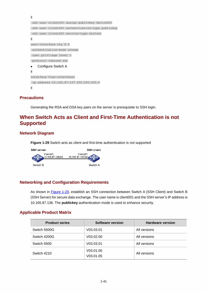
1-41
#
ssh user client001 assign publickey Switch001
ssh user client001 authentication-type publickey
ssh user client001 service-type stelnet
#
user-interface vty 0 4
authentication-mode scheme
user privilege level 3
protocol inbound ssh
Configure Switch A #
interface Vlan-interface1
ip address 10.165.87.137 255.255.255.0
#
Precautions
Generating the RSA and DSA key pairs on the server is prerequisite to SSH login.
When Switch Acts as Client and First-Time Authentication is not Supported
Network Diagram
Figure 1-29 Switch acts as client and first-time authentication is not supported
Networking and Configuration Requirements
As shown in Figure 1-29, establish an SSH connection between Switch A (SSH Client) and Switch B (SSH Server) for secure data exchange. The user name is client001 and the SSH server’s IP address is 10.165.87.136. The publickey authentication mode is used to enhance security.
Applicable Product Matrix
Product series Software version Hardware version
Switch 5500G V03.03.01 All versions
Switch 4200G V03.02.00 All versions
Switch 5500 V03.03.01 All versions
Switch 4210 V03.01.00 V03.01.05
All versions
1-42
Configuration Procedure
Configure Switch B
# Create a VLAN interface on the switch and assign an IP address for it to serve as the destination of the client.
<SwitchB> system-view
[SwitchB] interface vlan-interface 1
[SwitchB-Vlan-interface1] ip address 10.165.87.136 255.255.255.0
[SwitchB-Vlan-interface1] quit
Generating the RSA and DSA key pairs on the server is prerequisite to SSH login.
# Generate RSA and DSA key pairs.
[SwitchB] public-key local create rsa
[SwitchB] public-key local create dsa
# Set AAA authentication on user interfaces.
[SwitchB] user-interface vty 0 4
[SwitchB-ui-vty0-4] authentication-mode scheme
# Configure the user interfaces to support SSH.
[SwitchB-ui-vty0-4] protocol inbound ssh
# Set the user command privilege level to 3.
[SwitchB-ui-vty0-4] user privilege level 3
[SwitchB-ui-vty0-4] quit
# Specify the authentication type for user client001 as publickey.
[SwitchB] ssh user client001 authentication-type publickey
Before doing the following steps, you must first generate a DSA key pair on the client and save the key pair in a file named Switch001, and then upload the file to the SSH server through FTP or TFTP. For details, refer to the following “Configure Switch A”.
# Import the client’s public key file Switch001 and name the public key as Switch001.
[SwitchB] public-key peer Switch001 import sshkey Switch001
# Assign public key Switch001 to user client001
[SwitchB] ssh user client001 assign publickey Switch001
# Export the generated DSA host public key pair to a file named Switch002.
[SwitchB] public-key local export dsa ssh2 Switch002
1-43
When first-time authentication is not supported, you must first generate a DSA key pair on the server and save the key pair in a file named Switch002, and then upload the file to the SSH client through FTP or TFTP.
Configure Switch A
# Create a VLAN interface on the switch and assign an IP address, which serves as the SSH client’s address in an SSH connection.
<SwitchA> system-view
[SwitchA] interface vlan-interface 1
[SwitchA-Vlan-interface1] ip address 10.165.87.137 255.255.255.0
[SwitchA-Vlan-interface1] quit
# Generate a DSA key pair
[SwitchA] public-key local create dsa
# Export the generated DSA key pair to a file named Switch001.
[SwitchA] public-key local export dsa ssh2 Switch001
After generating the key pair, you need to upload the key pair file to the server through FTP or TFTP and complete the server end configuration before you continue to configure the client.
# Disable first-time authentication on the device.
[SwitchA] undo ssh client first-time
When first-time authentication is not supported, you must first generate a DSA key pair on the server and save the key pair in a file named Switch002, and then upload the file to the SSH client through FTP or TFTP. For details, refer to the above part “Configure Switch B”.
# Import the public key pair named Switch002 from the file Switch002.
[SwitchA] public-key peer Switch002 import sshkey Switch002
# Specify the host public key pair name of the server.
[SwitchA] ssh client 10.165.87.136 assign publickey Switch002
# Establish the SSH connection to server 10.165.87.136.
[SwitchA] ssh2 10.165.87.136 identity-key dsa
Username: client001
Trying 10.165.87.136 ...
Press CTRL+K to abort

1-44
Connected to 10.165.87.136 ...
********************************************************************************
* Copyright(c) 2004-2008 3Com Corp. and its licensors. All rights reserved. *
* Without the owner's prior written consent, *
* no decompiling or reverse-engineering shall be allowed. *
********************************************************************************
<SwitchB>
Complete Configuration
Configure Switch B #
public-key peer Switch001
public-key-code begin
308201B73082012C06072A8648CE3804013082011F02818100D757262C4584C44C211F18BD
96E5F061C4F0A423F7FE6B6B85B34CEF72CE14A0D3A5222FE08CECE65BE6C265854889DC1E
DBD13EC8B274DA9F75BA26CCB987723602787E922BA84421F22C3C89CB9B06FD60FE01941D
DD77FE6B12893DA76EEBC1D128D97F0678D7722B5341C8506F358214B16A2FAC4B36895038
7811C7DA33021500C773218C737EC8EE993B4F2DED30F48EDACE915F0281810082269009E1
4EC474BAF2932E69D3B1F18517AD9594184CCDFCEAE96EC4D5EF93133E84B47093C52B20CD
35D02492B3959EC6499625BC4FA5082E22C5B374E16DD00132CE71B020217091AC717B6123
91C76C1FB2E88317C1BD8171D41ECB83E210C03CC9B32E810561C21621C73D6DAAC028F4B1
585DA7F42519718CC9B09EEF0381840002818066E34E6F395E111C559A97BCB67B019DAA4C
4292E4AF541F71DD16A4CE6463F55491B38B24E5F7DC7CFD0B80F6E61916C60DB29DC62B44
AFC87ED3725AB6592BE5F2D3BA64BC1ACC5642D493C64A915157514D0C94A0019BBB38E7B8
092765BB30FB45C78C2B7EF564BF8F0C27E9A923675DCCEEAC193413BD120D43652A149E
public-key-code end
peer-public-key end
#
vlan 1
#
interface Vlan-interface1
ip address 10.165.87.136 255.255.255.0
#
ssh user client001 assign publickey Switch001
ssh user client001 authentication-type publickey
ssh user client001 service-type stelnet
#
user-interface vty 0 4
authentication-mode scheme
user privilege level 3
protocol inbound ssh
#
Configure Switch A #
public-key peer Switch002
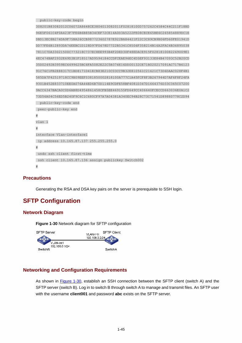
1-45
public-key-code begin
308201B83082012C06072A8648CE3804013082011F02818100D757262C4584C44C211F18BD
96E5F061C4F0A423F7FE6B6B85B34CEF72CE14A0D3A5222FE08CECE65BE6C265854889DC1E
DBD13EC8B274DA9F75BA26CCB987723602787E922BA84421F22C3C89CB9B06FD60FE01941D
DD77FE6B12893DA76EEBC1D128D97F0678D7722B5341C8506F358214B16A2FAC4B36895038
7811C7DA33021500C773218C737EC8EE993B4F2DED30F48EDACE915F0281810082269009E1
4EC474BAF2932E69D3B1F18517AD9594184CCDFCEAE96EC4D5EF93133E84B47093C52B20CD
35D02492B3959EC6499625BC4FA5082E22C5B374E16DD00132CE71B020217091AC717B6123
91C76C1FB2E88317C1BD8171D41ECB83E210C03CC9B32E810561C21621C73D6DAAC028F4B1
585DA7F42519718CC9B09EEF0381850002818100A777C1A45FCF8F3B267944D7AF6F8F24FA
9301B452E833710EE0A076A44ED6B70D114E9CDFE58BF4081D347D1664376D33C365C07200
9ACC6347BACA0C0D6AB8D4954861458CFB5EE469155FD649CC406640FCECCD663036E0A1C2
73D56A04C56ED5B240F9C6C1C680CF97A7A04381A340EC94B28C73C71541D89880778C2D94
public-key-code end
peer-public-key end
#
vlan 1
#
interface Vlan-interface1
ip address 10.165.87.137 255.255.255.0
#
undo ssh client first-time
ssh client 10.165.87.136 assign publickey Switch002
#
Precautions
Generating the RSA and DSA key pairs on the server is prerequisite to SSH login.
SFTP Configuration
Network Diagram
Figure 1-30 Network diagram for SFTP configuration
Networking and Configuration Requirements
As shown in Figure 1-30, establish an SSH connection between the SFTP client (switch A) and the SFTP server (switch B). Log in to switch B through switch A to manage and transmit files. An SFTP user with the username client001 and password abc exists on the SFTP server.
1-46
Applicable Product Matrix
Product series Software version Hardware version
Switch 5500G V03.03.01 All versions
Switch 4200G V03.02.00 All versions
Switch 5500 V03.03.01 All versions
Switch 4500 V03.03.00 All versions
Switch 4210 V03.01.00 V03.01.05
All versions
Configuration Procedure
1) Configure the SFTP server (switch B)
# Create key pairs.
<SwitchB> system-view
[SwitchB] public-key local create rsa
[SwitchB] public-key local create dsa
Generating the RSA and DSA key pairs on the server is prerequisite to SFTP login. The 4500 switch supports RSA key pair only.
# Create a VLAN interface on the switch and assign to it an IP address, which is used as the destination address for the client to connect to the SFTP server.
[SwitchB] interface vlan-interface 1
[SwitchB-Vlan-interface1] ip address 192.168.0.1 255.255.255.0
[SwitchB-Vlan-interface1] quit
# Specify the SSH authentication mode as AAA.
[SwitchB] user-interface vty 0 4
[SwitchB-ui-vty0-4] authentication-mode scheme
# Configure the protocol through which the remote user logs in to the switch as SSH.
[SwitchB-ui-vty0-4] protocol inbound ssh
[SwitchB-ui-vty0-4] quit
# Create a local user client001.
[SwitchB] local-user client001
[SwitchB-luser-client001] password simple abc
[SwitchB-luser-client001] service-type ssh
[SwitchB-luser-client001] quit
# Configure the authentication mode as password. Authentication timeout time, retry number, and update time of the server key adopt the default values.
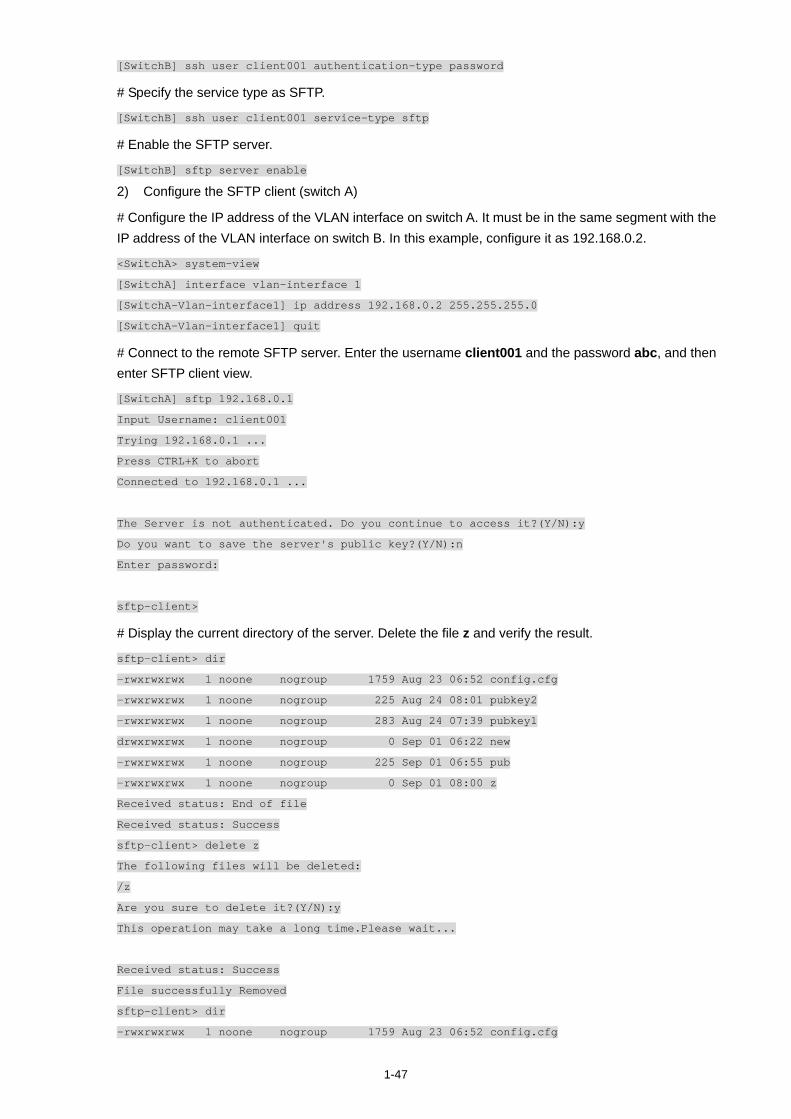
1-47
[SwitchB] ssh user client001 authentication-type password
# Specify the service type as SFTP.
[SwitchB] ssh user client001 service-type sftp
# Enable the SFTP server.
[SwitchB] sftp server enable
2) Configure the SFTP client (switch A)
# Configure the IP address of the VLAN interface on switch A. It must be in the same segment with the IP address of the VLAN interface on switch B. In this example, configure it as 192.168.0.2.
<SwitchA> system-view
[SwitchA] interface vlan-interface 1
[SwitchA-Vlan-interface1] ip address 192.168.0.2 255.255.255.0
[SwitchA-Vlan-interface1] quit
# Connect to the remote SFTP server. Enter the username client001 and the password abc, and then enter SFTP client view.
[SwitchA] sftp 192.168.0.1
Input Username: client001
Trying 192.168.0.1 ...
Press CTRL+K to abort
Connected to 192.168.0.1 ...
The Server is not authenticated. Do you continue to access it?(Y/N):y
Do you want to save the server's public key?(Y/N):n
Enter password:
sftp-client>
# Display the current directory of the server. Delete the file z and verify the result.
sftp-client> dir
-rwxrwxrwx 1 noone nogroup 1759 Aug 23 06:52 config.cfg
-rwxrwxrwx 1 noone nogroup 225 Aug 24 08:01 pubkey2
-rwxrwxrwx 1 noone nogroup 283 Aug 24 07:39 pubkey1
drwxrwxrwx 1 noone nogroup 0 Sep 01 06:22 new
-rwxrwxrwx 1 noone nogroup 225 Sep 01 06:55 pub
-rwxrwxrwx 1 noone nogroup 0 Sep 01 08:00 z
Received status: End of file
Received status: Success
sftp-client> delete z
The following files will be deleted:
/z
Are you sure to delete it?(Y/N):y
This operation may take a long time.Please wait...
Received status: Success
File successfully Removed
sftp-client> dir
-rwxrwxrwx 1 noone nogroup 1759 Aug 23 06:52 config.cfg

1-48
-rwxrwxrwx 1 noone nogroup 225 Aug 24 08:01 pubkey2
-rwxrwxrwx 1 noone nogroup 283 Aug 24 07:39 pubkey1
drwxrwxrwx 1 noone nogroup 0 Sep 01 06:22 new
-rwxrwxrwx 1 noone nogroup 225 Sep 01 06:55 pub
Received status: End of file
Received status: Success
# Add a directory new1, and then check whether the new directory is successfully created.
sftp-client> mkdir new1
Received status: Success
New directory created
sftp-client> dir
-rwxrwxrwx 1 noone nogroup 1759 Aug 23 06:52 config.cfg
-rwxrwxrwx 1 noone nogroup 225 Aug 24 08:01 pubkey2
-rwxrwxrwx 1 noone nogroup 283 Aug 24 07:39 pubkey1
drwxrwxrwx 1 noone nogroup 0 Sep 01 06:22 new
-rwxrwxrwx 1 noone nogroup 225 Sep 01 06:55 pub
drwxrwxrwx 1 noone nogroup 0 Sep 02 06:30 new1
Received status: End of file
Received status: Success
# Rename the directory new1 as new2, and then verify the result.
sftp-client> rename new1 new2
File successfully renamed
sftp-client> dir
-rwxrwxrwx 1 noone nogroup 1759 Aug 23 06:52 config.cfg
-rwxrwxrwx 1 noone nogroup 225 Aug 24 08:01 pubkey2
-rwxrwxrwx 1 noone nogroup 283 Aug 24 07:39 pubkey1
drwxrwxrwx 1 noone nogroup 0 Sep 01 06:22 new
-rwxrwxrwx 1 noone nogroup 225 Sep 01 06:55 pub
drwxrwxrwx 1 noone nogroup 0 Sep 02 06:33 new2
Received status: End of file
Received status: Success
# Download the file pubkey2 from the server and rename it as public.
sftp-client> get pubkey2 public
This operation may take a long time, please wait...
.
Remote file:/pubkey2 ---> Local file: public..
Received status: End of file
Received status: Success
Downloading file successfully ended
# Upload file pu to the server and rename it as puk, and then verify the result.
sftp-client> put pu puk
This operation may take a long time, please wait...
Local file: pu ---> Remote file: /puk
Received status: Success
Uploading file successfully ended
sftp-client> dir
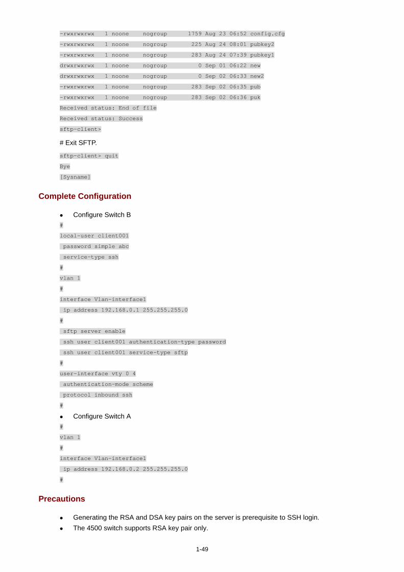
1-49
-rwxrwxrwx 1 noone nogroup 1759 Aug 23 06:52 config.cfg
-rwxrwxrwx 1 noone nogroup 225 Aug 24 08:01 pubkey2
-rwxrwxrwx 1 noone nogroup 283 Aug 24 07:39 pubkey1
drwxrwxrwx 1 noone nogroup 0 Sep 01 06:22 new
drwxrwxrwx 1 noone nogroup 0 Sep 02 06:33 new2
-rwxrwxrwx 1 noone nogroup 283 Sep 02 06:35 pub
-rwxrwxrwx 1 noone nogroup 283 Sep 02 06:36 puk
Received status: End of file
Received status: Success
sftp-client>
# Exit SFTP.
sftp-client> quit
Bye
[Sysname]
Complete Configuration
Configure Switch B #
local-user client001
password simple abc
service-type ssh
#
vlan 1
#
interface Vlan-interface1
ip address 192.168.0.1 255.255.255.0
#
sftp server enable
ssh user client001 authentication-type password
ssh user client001 service-type sftp
#
user-interface vty 0 4
authentication-mode scheme
protocol inbound ssh
#
Configure Switch A #
vlan 1
#
interface Vlan-interface1
ip address 192.168.0.2 255.255.255.0
#
Precautions
Generating the RSA and DSA key pairs on the server is prerequisite to SSH login. The 4500 switch supports RSA key pair only.
i
Table of Contents
1 FTP and TFTP Configuring Guide············································································································1-1 Configuring a Switch as FTP Server·······································································································1-1
Network Diagram·····························································································································1-1 Networking and Configuration Requirements··················································································1-1 Applicable Product Matrix················································································································1-1 Configuration Procedure··················································································································1-2 Complete Configuration···················································································································1-2 Precautions······································································································································1-3
Configuring a Switch as FTP Client ········································································································1-3 Network Diagram·····························································································································1-3 Networking and Configuration Requirements··················································································1-3 Applicable Product Matrix················································································································1-3 Configuration Procedure··················································································································1-4 Complete Configuration···················································································································1-5 Precautions······································································································································1-5
Configuring a Switch as TFTP Client ······································································································1-5 Network Diagram·····························································································································1-6 Networking and Configuration Requirements··················································································1-6 Applicable Product Matrix················································································································1-6 Configuration Procedure··················································································································1-6 Complete Configuration···················································································································1-7 Precautions······································································································································1-7
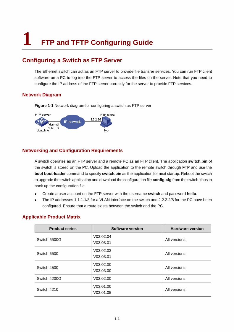
1-1
1 FTP and TFTP Configuring Guide
Configuring a Switch as FTP Server
The Ethernet switch can act as an FTP server to provide file transfer services. You can run FTP client software on a PC to log into the FTP server to access the files on the server. Note that you need to configure the IP address of the FTP server correctly for the server to provide FTP services.
Network Diagram
Figure 1-1 Network diagram for configuring a switch as FTP server
Networking and Configuration Requirements
A switch operates as an FTP server and a remote PC as an FTP client. The application switch.bin of the switch is stored on the PC. Upload the application to the remote switch through FTP and use the boot boot-loader command to specify switch.bin as the application for next startup. Reboot the switch to upgrade the switch application and download the configuration file config.cfg from the switch, thus to back up the configuration file.
Create a user account on the FTP server with the username switch and password hello. The IP addresses 1.1.1.1/8 for a VLAN interface on the switch and 2.2.2.2/8 for the PC have been
configured. Ensure that a route exists between the switch and the PC.
Applicable Product Matrix
Product series Software version Hardware version
Switch 5500G V03.02.04 V03.03.01
All versions
Switch 5500 V03.02.03 V03.03.01
All versions
Switch 4500 V03.02.00 V03.03.00
All versions
Switch 4200G V03.02.00 All versions
Switch 4210 V03.01.00 V03.01.05
All versions
1-2
Configuration Procedure
Configure Switch A (the FTP server)
# Log in to the switch and assign IP address 1.1.1.1/8 to VLAN-interface 1.
<Sysname> system-view
[Sysname] interface Vlan-interface 1
[Sysname-Vlan-interface1] ip address 1.1.1.1 8
[Sysname-Vlan-interface1] quit
# Enable the FTP server function, and configure the username and password for the FTP client to access FTP services.
[Sysname] ftp server enable
[Sysname] local-user switch
[Sysname-luser-switch] password simple hello
[Sysname-luser-switch] service-type ftp
Configure the PC (FTP client)
Run an FTP client application on the PC to connect to the FTP server. The following takes the command line window tool provided by Windows as an example:
# Enter the command line window and browse to the directory where the file switch.bin is located. In this example it is in the root directory of C:\.
C:\>
# Access the Ethernet switch through FTP. Input the username switch and password hello to log in and enter FTP view.
C:\> ftp 1.1.1.1
Connected to 1.1.1.1.
220 FTP service ready.
User (1.1.1.1:(none)): switch
331 Password required for switch.
Password:
230 User logged in.
ftp>
# Upload file switch.bin.
ftp> put switch.bin
# Download file config.cfg.
ftp> get config.cfg
Upgrade the application of the switch.
# Use the boot boot-loader command to specify the uploaded application to be the startup file for next startup and restart the switch to complete the switch application upgrade.
<Sysname> boot boot-loader switch.bin
<Sysname> reboot
Complete Configuration
Configure the switch A
#
local-user switch
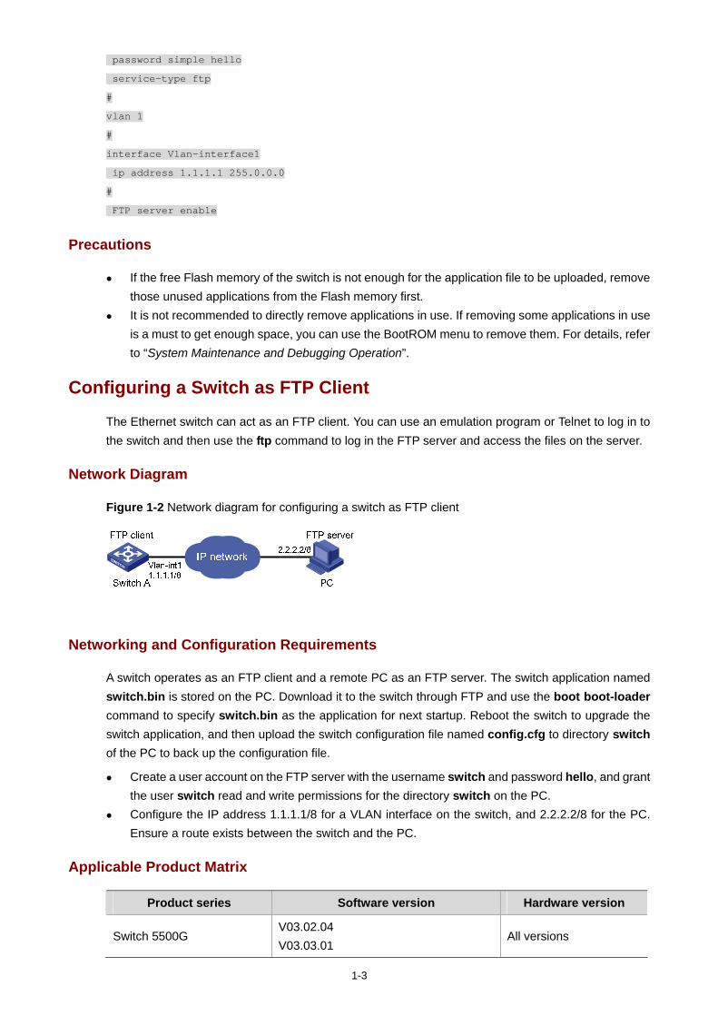
1-3
password simple hello
service-type ftp
#
vlan 1
#
interface Vlan-interface1
ip address 1.1.1.1 255.0.0.0
#
FTP server enable
Precautions
If the free Flash memory of the switch is not enough for the application file to be uploaded, remove those unused applications from the Flash memory first.
It is not recommended to directly remove applications in use. If removing some applications in use is a must to get enough space, you can use the BootROM menu to remove them. For details, refer to “System Maintenance and Debugging Operation”.
Configuring a Switch as FTP Client
The Ethernet switch can act as an FTP client. You can use an emulation program or Telnet to log in to the switch and then use the ftp command to log in the FTP server and access the files on the server.
Network Diagram
Figure 1-2 Network diagram for configuring a switch as FTP client
Networking and Configuration Requirements
A switch operates as an FTP client and a remote PC as an FTP server. The switch application named switch.bin is stored on the PC. Download it to the switch through FTP and use the boot boot-loader command to specify switch.bin as the application for next startup. Reboot the switch to upgrade the switch application, and then upload the switch configuration file named config.cfg to directory switch of the PC to back up the configuration file.
Create a user account on the FTP server with the username switch and password hello, and grant the user switch read and write permissions for the directory switch on the PC.
Configure the IP address 1.1.1.1/8 for a VLAN interface on the switch, and 2.2.2.2/8 for the PC. Ensure a route exists between the switch and the PC.
Applicable Product Matrix
Product series Software version Hardware version
Switch 5500G V03.02.04 V03.03.01
All versions
1-4
Product series Software version Hardware version
Switch 5500 V03.02.03 V03.03.01
All versions
Switch 4500 V03.02.00 V03.03.00
All versions
Switch 4200G V03.02.00 All versions
Switch 4210 V03.01.00 V03.01.05
All versions
Configuration Procedure
Configure the PC (FTP server)
Perform FTP service-related configurations on the PC, that is, create a user account on the FTP server with the username switch and password hello. For detailed configuration, refer to the configuration instruction of the FTP server software.
Configure the switch (FTP client)
# Log in to the switch and assign IP address 1.1.1.1/8 to VLAN-interface 1.
<Sysname>
<Sysname> system-view
[Sysname] interface Vlan-interface 1
[Sysname-Vlan-interface1] ip address 1.1.1.1 8
[Sysname-Vlan-interface1] return
# Connect to the FTP server using the ftp command in user view. You need to provide the username and password to log in to the FTP server.
<Sysname> ftp 2.2.2.2
Trying ...
Press CTRL+K to abort
Connected.
220 FTP service ready.
User(none):switch
331 Password required for switch.
Password:
230 User logged in.
[ftp]
# Switch data transfer mode to binary.
[ftp] binary
You are recommended to set the transfer mode to binary before performing data transfer operation, so as to ensure that the device can receive data normally.
1-5
# Browse to the authorized directory on the FTP server, upload configuration file config.cfg to the FTP server, and download the file named switch.bin. Then, terminate the FTP connection and return to user view.
Before downloading a file, use the dir command to check that the remaining space of the Flash memory is enough for the file to be downloaded.
[ftp] cd switch
[ftp] put config.cfg
[ftp] get switch.bin
[ftp] quit
<Sysname>
# Use the boot boot-loader command to specify the downloaded file as the application for next startup and then restart the switch. Thus the switch application is upgraded.
<Sysname> boot boot-loader switch.bin
<Sysname> reboot
Complete Configuration
#
vlan 1
#
interface Vlan-interface1
ip address 1.1.1.1 255.0.0.0
Precautions
If the free Flash memory of the switch is not enough for downloading the application file from the FTP server, remove those unused applications from the Flash memory before downloading the file.
It is not recommended to directly remove applications in use. If removing some applications in use is a must to get enough space, you can use the BootROM menu to remove them. For details, refer to “System Maintenance and Debugging Operation”.
Configuring a Switch as TFTP Client
Compared with FTP, Trivial File Transfer Protocol (TFTP) features simple interactive interface with no authentication control and is therefore applicable to the networks where client-server interactions are relatively simple.
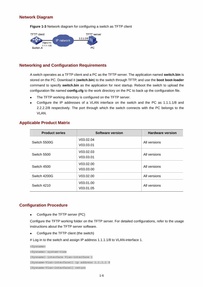
1-6
Network Diagram
Figure 1-3 Network diagram for configuring a switch as TFTP client
Networking and Configuration Requirements
A switch operates as a TFTP client and a PC as the TFTP server. The application named switch.bin is stored on the PC. Download it (switch.bin) to the switch through TFTP, and use the boot boot-loader command to specify switch.bin as the application for next startup. Reboot the switch to upload the configuration file named config.cfg to the work directory on the PC to back up the configuration file.
The TFTP working directory is configured on the TFTP server. Configure the IP addresses of a VLAN interface on the switch and the PC as 1.1.1.1/8 and
2.2.2.2/8 respectively. The port through which the switch connects with the PC belongs to the VLAN.
Applicable Product Matrix
Product series Software version Hardware version
Switch 5500G V03.02.04 V03.03.01
All versions
Switch 5500 V03.02.03 V03.03.01
All versions
Switch 4500 V03.02.00 V03.03.00
All versions
Switch 4200G V03.02.00 All versions
Switch 4210 V03.01.00 V03.01.05
All versions
Configuration Procedure
Configure the TFTP server (PC)
Configure the TFTP working folder on the TFTP server. For detailed configurations, refer to the usage instructions about the TFTP server software.
Configure the TFTP client (the switch)
# Log in to the switch and assign IP address 1.1.1.1/8 to VLAN-interface 1.
<Sysname>
<Sysname> system-view
[Sysname] interface Vlan-interface 1
[Sysname-Vlan-interface1] ip address 1.1.1.1 8
[Sysname-Vlan-interface1] return
1-7
# Download the switch application named switch.bin from the TFTP server to the switch, and upload the switch configuration file named config.cfg to the TFTP server.
<Sysname> tftp 2.2.2.2 get switch.bin switch.bin
<Sysname> tftp 2.2.2.2 put config.cfg config.cfg
# Use the boot boot-loader command to specify the downloaded file to be the startup file for next startup of the switch and restart the switch to complete the switch application upgrade.
<Sysname> boot boot-loader switch.bin
<Sysname> reboot
Complete Configuration
Configure the switch #
vlan 1
#
interface Vlan-interface1
ip address 1.1.1.1 255.0.0.0
Precautions
If the free Flash memory of the switch is not enough for downloading the application file from the TFTP server, remove those unused applications from the Flash memory before downloading the file.
It is not recommended to directly remove applications in use. If removing some applications in use is a must to get enough space, you can use the BootROM menu to remove them. For details, refer to “System Maintenance and Debugging Operation”.
i
Table of Contents
1 Information Center Configuration Guide·································································································1-1 Outputting Log Information to a Unix Log Host·······················································································1-1
Network Diagram·····························································································································1-1 Networking and Configuration Requirements··················································································1-1 Applicable Product Matrix················································································································1-1 Configuration Procedure··················································································································1-1 Complete Configuration···················································································································1-2 Precautions······································································································································1-2
Outputting Log Information to a Linux Log Host ·····················································································1-3 Network Diagram·····························································································································1-3 Networking and Configuration Requirements··················································································1-3 Applicable Product Matrix················································································································1-3 Configuration Procedure··················································································································1-3 Complete Configuration···················································································································1-4 Precautions······································································································································1-4
Outputting Log and Trap Information to a Log Host Through the Same Channel··································1-5 Network Diagram·····························································································································1-5 Networking and Configuration Requirements··················································································1-5 Applicable Product Matrix················································································································1-5 Configuration Procedure··················································································································1-5 Complete Configuration···················································································································1-7 Precautions······································································································································1-7
Outputting Log Information to the Console ·····························································································1-7 Network Diagram·····························································································································1-7 Networking and Configuration Requirements··················································································1-7 Applicable Product Matrix················································································································1-7 Configuration Procedure··················································································································1-8 Complete Configuration···················································································································1-8 Precautions······································································································································1-8
Displaying the Time Stamp with the UTC Time Zone·············································································1-9 Network Diagram·····························································································································1-9 Networking and Configuration Requirements··················································································1-9 Applicable Product Matrix················································································································1-9 Configuration Procedure··················································································································1-9 Complete Configuration···················································································································1-9 Precautions····································································································································1-10
Use of the Facility Argument in Log Information Output ·······································································1-10 Network Diagram···························································································································1-10 Networking and Configuration Requirements················································································1-10 Network Requirements Analysis ···································································································1-10 Applicable Product Matrix··············································································································1-10 Configuration Procedure················································································································1-11 Complete Configuration·················································································································1-11

ii
Precautions····································································································································1-11
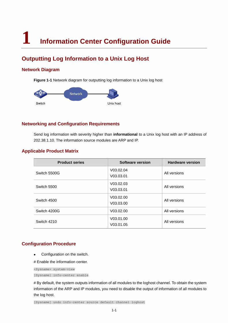
1-1
1 Information Center Configuration Guide
Outputting Log Information to a Unix Log Host
Network Diagram
Figure 1-1 Network diagram for outputting log information to a Unix log host
Networking and Configuration Requirements
Send log information with severity higher than informational to a Unix log host with an IP address of 202.38.1.10. The information source modules are ARP and IP.
Applicable Product Matrix
Product series Software version Hardware version
Switch 5500G V03.02.04 V03.03.01
All versions
Switch 5500 V03.02.03 V03.03.01
All versions
Switch 4500 V03.02.00 V03.03.00
All versions
Switch 4200G V03.02.00 All versions
Switch 4210 V03.01.00 V03.01.05
All versions
Configuration Procedure
Configuration on the switch.
# Enable the information center.
<Sysname> system-view
[Sysname] info-center enable
# By default, the system outputs information of all modules to the loghost channel. To obtain the system information of the ARP and IP modules, you need to disable the output of information of all modules to the log host.
[Sysname] undo info-center source default channel loghost
1-2
# Set the host with an IP address of 202.38.1.10 to be the log host, set the severity to informational, and the information source modules to ARP and IP.
[Sysname] info-center loghost 202.38.1.10 facility local4
[Sysname] info-center source arp channel loghost log level informational debug state off trap
state off
[Sysname] info-center source ip channel loghost log level informational debug state off trap
state off
Configuration on the log host.
The following configurations were performed on SunOS 4.0 which has similar configurations with the Unix operating systems implemented by other vendors.
# Execute the following commands as a root user.
# mkdir /var/log/Switch
# touch /var/log/Switch/information
# Edit the file /etc/syslog.conf as a root user and add the following selector/action pairs.
# Switch configuration messages
local4.info /var/log/Switch/information
# After the log file information has been created and the configuration file /etc/syslog.conf has been modified, ensure that the configuration file /etc/syslog.conf is reread by executing the following commands:
# ps -ae | grep syslogd
147
# kill -HUP 147
Complete Configuration
Configuration on the switch. #
info-center source ARP channel 2 trap state off
info-center source IP channel 2 trap state off
undo info-center source default channel 2
info-center loghost 202.38.1.10 facility local4
Configuration on the log host. #
# mkdir /var/log/Switch
# touch /var/log/Switch/information
# Switch configuration messages
local4.info /var/log/Switch/information
#
# ps -ae | grep syslogd
147
# kill -HUP 147
Precautions
Note the following issues while editing the /etc/syslog.conf file:
Comments must be on a separate line and must begin with the # sign.
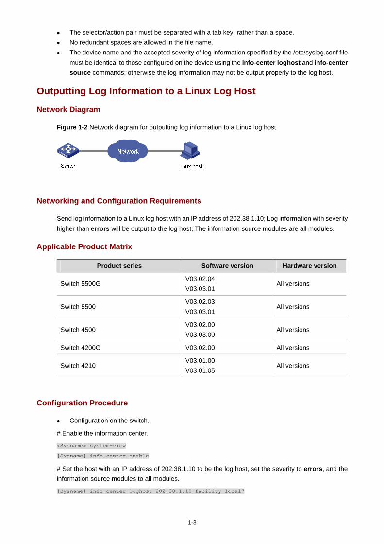
1-3
The selector/action pair must be separated with a tab key, rather than a space. No redundant spaces are allowed in the file name. The device name and the accepted severity of log information specified by the /etc/syslog.conf file
must be identical to those configured on the device using the info-center loghost and info-center source commands; otherwise the log information may not be output properly to the log host.
Outputting Log Information to a Linux Log Host
Network Diagram
Figure 1-2 Network diagram for outputting log information to a Linux log host
Networking and Configuration Requirements
Send log information to a Linux log host with an IP address of 202.38.1.10; Log information with severity higher than errors will be output to the log host; The information source modules are all modules.
Applicable Product Matrix
Product series Software version Hardware version
Switch 5500G V03.02.04 V03.03.01
All versions
Switch 5500 V03.02.03 V03.03.01
All versions
Switch 4500 V03.02.00 V03.03.00
All versions
Switch 4200G V03.02.00 All versions
Switch 4210 V03.01.00 V03.01.05
All versions
Configuration Procedure
Configuration on the switch.
# Enable the information center.
<Sysname> system-view
[Sysname] info-center enable
# Set the host with an IP address of 202.38.1.10 to be the log host, set the severity to errors, and the information source modules to all modules.
[Sysname] info-center loghost 202.38.1.10 facility local7
1-4
[Sysname] info-center source default channel loghost log level errors debug state off trap
state off
Configuration on the log host.
# Execute the following commands as a root user.
# mkdir /var/log/Switch
# touch /var/log/Switch/information
# Edit the file /etc/syslog.conf as a root user and add the following selector/action pairs.
# Switch configuration messages
local7.info /var/log/Switch/information
# After the log file information has been created and the /etc/syslog.conf file has been modified, execute the following commands to display the process ID of syslogd, terminate a syslogd process, and restart syslogd using the -r option.
# ps -ae | grep syslogd
147
# kill -9 147
# syslogd -r &
Complete Configuration
Configuration on the switch. #
info-center source default channel 2 log level error trap state off
info-center loghost 202.38.1.10
Configuration on the log host. #
# mkdir /var/log/Switch
# touch /var/log/Switch/information
# Switch configuration messages
local7.info /var/log/Switch/information
#
# ps -ae | grep syslogd
147
# kill -9 147
# syslogd -r &
Precautions
Ensure that the syslogd process is started with the -r option on a Linux log host.
Note the following issues while editing the /etc/syslog.conf file:
Comments must be on a separate line and must begin with the # sign. The selector/action pair must be separated with a tab key, rather than a space. No redundant spaces are allowed in the file name. The device name and the accepted severity of log information specified by the /etc/syslog.conf file
must be identical to those configured on the device using the info-center loghost and info-center source commands; otherwise the log information may not be output properly to the log host.
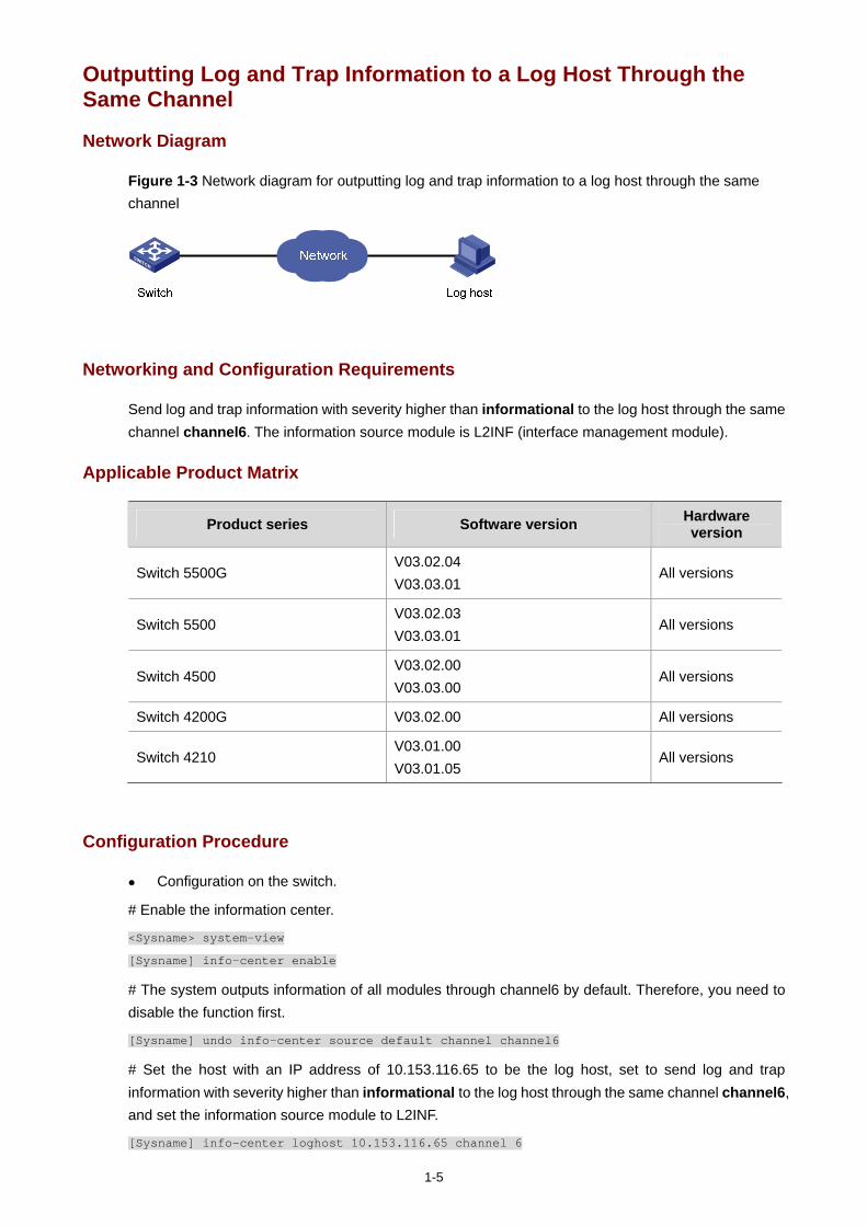
1-5
Outputting Log and Trap Information to a Log Host Through the Same Channel
Network Diagram
Figure 1-3 Network diagram for outputting log and trap information to a log host through the same channel
Networking and Configuration Requirements
Send log and trap information with severity higher than informational to the log host through the same channel channel6. The information source module is L2INF (interface management module).
Applicable Product Matrix
Product series Software version Hardware version
Switch 5500G V03.02.04 V03.03.01
All versions
Switch 5500 V03.02.03 V03.03.01
All versions
Switch 4500 V03.02.00 V03.03.00
All versions
Switch 4200G V03.02.00 All versions
Switch 4210 V03.01.00 V03.01.05
All versions
Configuration Procedure
Configuration on the switch.
# Enable the information center.
<Sysname> system-view
[Sysname] info-center enable
# The system outputs information of all modules through channel6 by default. Therefore, you need to disable the function first.
[Sysname] undo info-center source default channel channel6
# Set the host with an IP address of 10.153.116.65 to be the log host, set to send log and trap information with severity higher than informational to the log host through the same channel channel6, and set the information source module to L2INF.
[Sysname] info-center loghost 10.153.116.65 channel 6
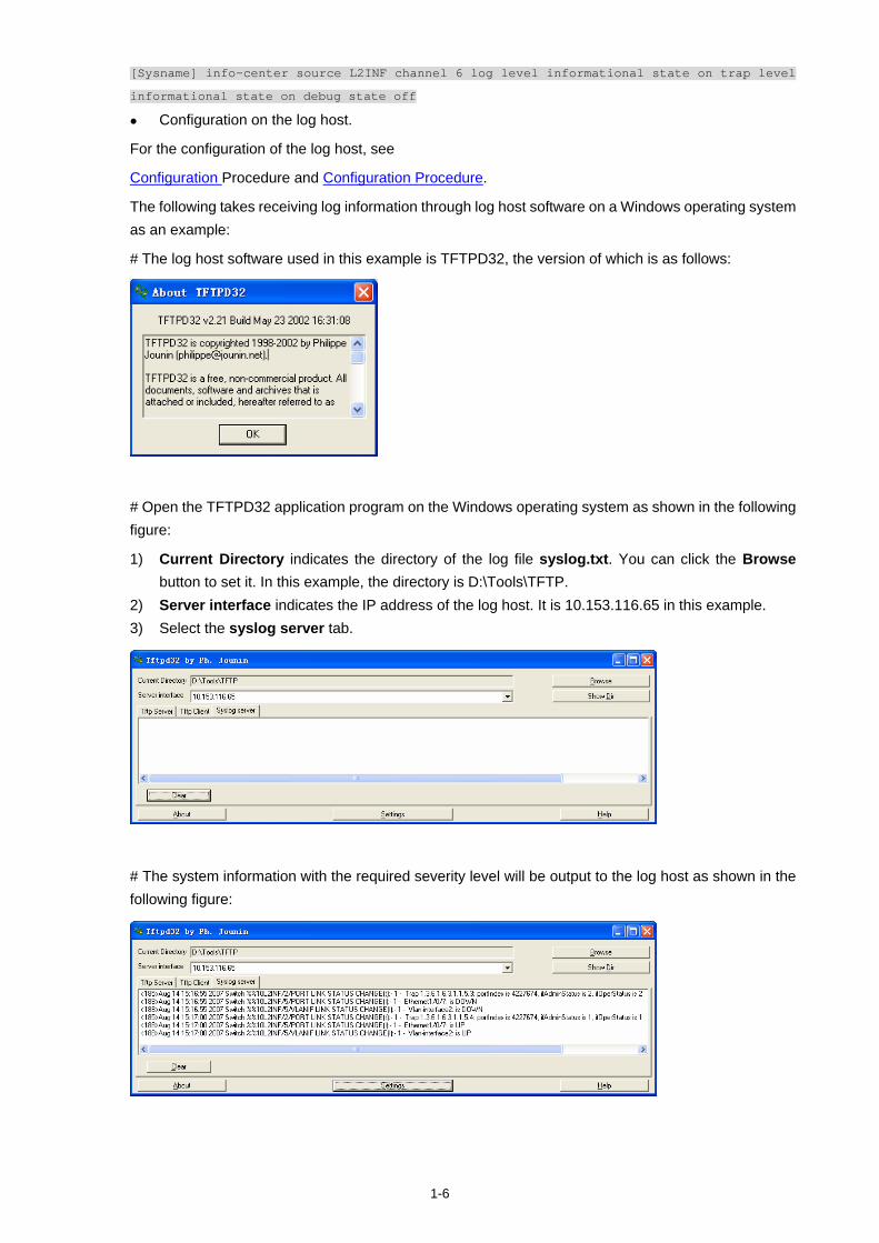
1-6
[Sysname] info-center source L2INF channel 6 log level informational state on trap level
informational state on debug state off
Configuration on the log host.
For the configuration of the log host, see
Configuration Procedure and Configuration Procedure.
The following takes receiving log information through log host software on a Windows operating system as an example:
# The log host software used in this example is TFTPD32, the version of which is as follows:
# Open the TFTPD32 application program on the Windows operating system as shown in the following figure:
1) Current Directory indicates the directory of the log file syslog.txt. You can click the Browse button to set it. In this example, the directory is D:\Tools\TFTP.
2) Server interface indicates the IP address of the log host. It is 10.153.116.65 in this example. 3) Select the syslog server tab.
# The system information with the required severity level will be output to the log host as shown in the following figure:
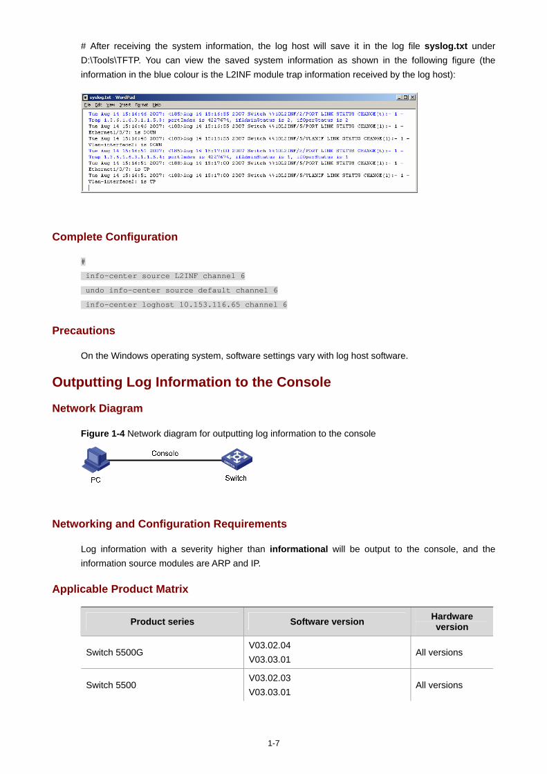
1-7
# After receiving the system information, the log host will save it in the log file syslog.txt under D:\Tools\TFTP. You can view the saved system information as shown in the following figure (the information in the blue colour is the L2INF module trap information received by the log host):
Complete Configuration
#
info-center source L2INF channel 6
undo info-center source default channel 6
info-center loghost 10.153.116.65 channel 6
Precautions
On the Windows operating system, software settings vary with log host software.
Outputting Log Information to the Console
Network Diagram
Figure 1-4 Network diagram for outputting log information to the console
Networking and Configuration Requirements
Log information with a severity higher than informational will be output to the console, and the information source modules are ARP and IP.
Applicable Product Matrix
Product series Software version Hardware version
Switch 5500G V03.02.04 V03.03.01
All versions
Switch 5500 V03.02.03 V03.03.01
All versions
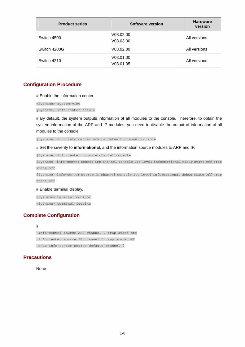
1-8
Product series Software version Hardware version
Switch 4500 V03.02.00 V03.03.00
All versions
Switch 4200G V03.02.00 All versions
Switch 4210 V03.01.00 V03.01.05
All versions
Configuration Procedure
# Enable the information center.
<Sysname> system-view
[Sysname] info-center enable
# By default, the system outputs information of all modules to the console. Therefore, to obtain the system information of the ARP and IP modules, you need to disable the output of information of all modules to the console.
[Sysname] undo info-center source default channel console
# Set the severity to informational, and the information source modules to ARP and IP.
[Sysname] info-center console channel console
[Sysname] info-center source arp channel console log level informational debug state off trap
state off
[Sysname] info-center source ip channel console log level informational debug state off trap
state off
# Enable terminal display.
<Sysname> terminal monitor
<Sysname> terminal logging
Complete Configuration
#
info-center source ARP channel 0 trap state off
info-center source IP channel 0 trap state off
undo info-center source default channel 0
Precautions
None
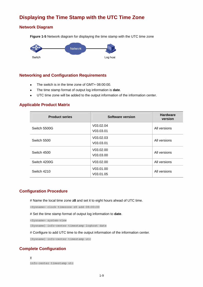
1-9
Displaying the Time Stamp with the UTC Time Zone
Network Diagram
Figure 1-5 Network diagram for displaying the time stamp with the UTC time zone
Networking and Configuration Requirements
The switch is in the time zone of GMT+ 08:00:00. The time stamp format of output log information is date. UTC time zone will be added to the output information of the information center.
Applicable Product Matrix
Product series Software version Hardware version
Switch 5500G V03.02.04 V03.03.01
All versions
Switch 5500 V03.02.03 V03.03.01
All versions
Switch 4500 V03.02.00 V03.03.00
All versions
Switch 4200G V03.02.00 All versions
Switch 4210 V03.01.00 V03.01.05
All versions
Configuration Procedure
# Name the local time zone z8 and set it to eight hours ahead of UTC time.
<Sysname> clock timezone z8 add 08:00:00
# Set the time stamp format of output log information to date.
<Sysname> system-view
[Sysname] info-center timestamp loghost date
# Configure to add UTC time to the output information of the information center.
[Sysname] info-center timestamp utc
Complete Configuration
#
info-center timestamp utc
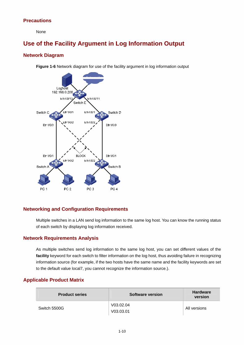
1-10
Precautions
None
Use of the Facility Argument in Log Information Output
Network Diagram
Figure 1-6 Network diagram for use of the facility argument in log information output
Networking and Configuration Requirements
Multiple switches in a LAN send log information to the same log host. You can know the running status of each switch by displaying log information received.
Network Requirements Analysis
As multiple switches send log information to the same log host, you can set different values of the facility keyword for each switch to filter information on the log host, thus avoiding failure in recognizing information source (for example, if the two hosts have the same name and the facility keywords are set to the default value local7, you cannot recognize the information source.).
Applicable Product Matrix
Product series Software version Hardware version
Switch 5500G V03.02.04 V03.03.01
All versions
1-11
Switch 5500 V03.02.03 V03.03.01
All versions
Switch 4500 V03.02.00 V03.03.00
All versions
Switch 4200G V03.02.00 All versions
Switch 4210 V03.01.00 V03.01.05
All versions
Configuration Procedure
Perform the following configurations on Switch A. [SwitchA]info-center enable
[SwitchA]info-center source default channel loghost log level debugging
[SwitchA]info-center loghost 192.168.0.208 facility local0 channel loghost
Perform the same configurations on Switch B, Switch C, Switch D and Switch E, and specify the facility argument as local1, local2, local3 and local4 respectively.
You can know the running status of all the devices by filtering information through the facility keyword.
Complete Configuration
Configuration on Switch A. #
info-center source default channel 2 log level debugging
info-center loghost 192.168.0.208 facility local0
Configuration on Switch B, Switch C, Switch D and Switch E.
<Omitted>
Precautions
None
i
Table of Contents
1 VLAN-VPN Configuration Guide ··············································································································1-1 Configuring VLAN-VPN···························································································································1-1
Network Diagram·····························································································································1-1 Networking and Configuration Requirements··················································································1-1 Applicable Product Matrix················································································································1-2 Configuration Procedure··················································································································1-2 Complete Configuration···················································································································1-3 Precautions······································································································································1-4
Configuring Selective QinQ·····················································································································1-4 Network Diagram·····························································································································1-5 Networking and Configuration Requirements··················································································1-5 Applicable Product Matrix················································································································1-5 Configuration Procedure··················································································································1-6 Complete Configuration···················································································································1-8 Precautions······································································································································1-9
Configuring BPDU Tunnel·······················································································································1-9 Network Diagram·····························································································································1-9 Networking and Configuration Requirements··················································································1-9 Applicable Product Matrix··············································································································1-10 Configuration Procedure················································································································1-10 Complete Configuration·················································································································1-10 Precautions····································································································································1-11
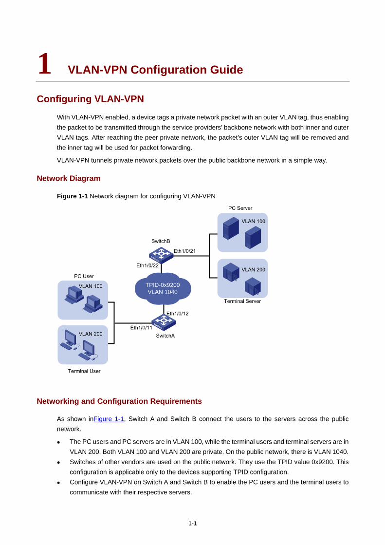
1-1
1 VLAN-VPN Configuration Guide
Configuring VLAN-VPN
With VLAN-VPN enabled, a device tags a private network packet with an outer VLAN tag, thus enabling the packet to be transmitted through the service providers’ backbone network with both inner and outer VLAN tags. After reaching the peer private network, the packet’s outer VLAN tag will be removed and the inner tag will be used for packet forwarding.
VLAN-VPN tunnels private network packets over the public backbone network in a simple way.
Network Diagram
Figure 1-1 Network diagram for configuring VLAN-VPN
TPID-0x9200VLAN 1040
Eth1/0/11
Eth1/0/12
Eth1/0/21
Eth1/0/22
VLAN 100
VLAN 200
PC User
Terminal User
SwitchA
SwitchB
VLAN 100
VLAN 200
PC Server
Terminal Server
Networking and Configuration Requirements
As shown inFigure 1-1, Switch A and Switch B connect the users to the servers across the public network.
The PC users and PC servers are in VLAN 100, while the terminal users and terminal servers are in VLAN 200. Both VLAN 100 and VLAN 200 are private. On the public network, there is VLAN 1040.
Switches of other vendors are used on the public network. They use the TPID value 0x9200. This configuration is applicable only to the devices supporting TPID configuration.
Configure VLAN-VPN on Switch A and Switch B to enable the PC users and the terminal users to communicate with their respective servers.
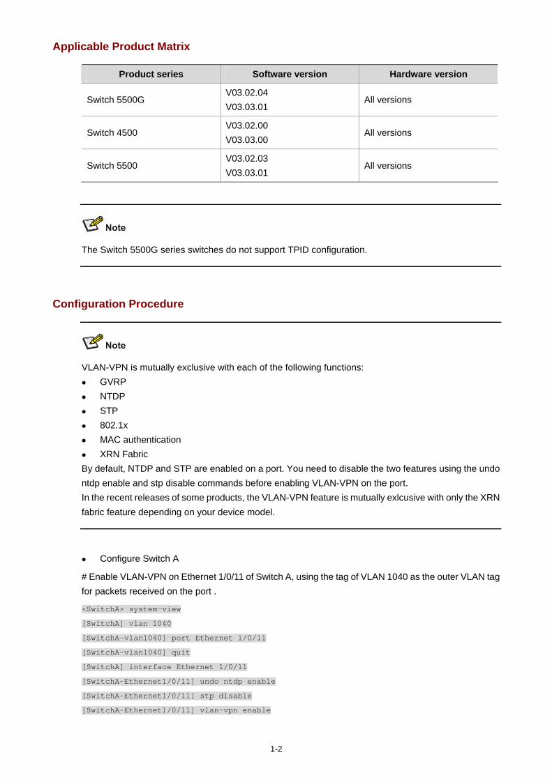
1-2
Applicable Product Matrix
Product series Software version Hardware version
Switch 5500G V03.02.04 V03.03.01
All versions
Switch 4500 V03.02.00 V03.03.00
All versions
Switch 5500 V03.02.03 V03.03.01
All versions
The Switch 5500G series switches do not support TPID configuration.
Configuration Procedure
VLAN-VPN is mutually exclusive with each of the following functions: GVRP NTDP STP 802.1x MAC authentication XRN Fabric
By default, NTDP and STP are enabled on a port. You need to disable the two features using the undo ntdp enable and stp disable commands before enabling VLAN-VPN on the port. In the recent releases of some products, the VLAN-VPN feature is mutually exlcusive with only the XRN fabric feature depending on your device model.
Configure Switch A
# Enable VLAN-VPN on Ethernet 1/0/11 of Switch A, using the tag of VLAN 1040 as the outer VLAN tag for packets received on the port .
<SwitchA> system-view
[SwitchA] vlan 1040
[SwitchA-vlan1040] port Ethernet 1/0/11
[SwitchA-vlan1040] quit
[SwitchA] interface Ethernet 1/0/11
[SwitchA-Ethernet1/0/11] undo ntdp enable
[SwitchA-Ethernet1/0/11] stp disable
[SwitchA-Ethernet1/0/11] vlan-vpn enable
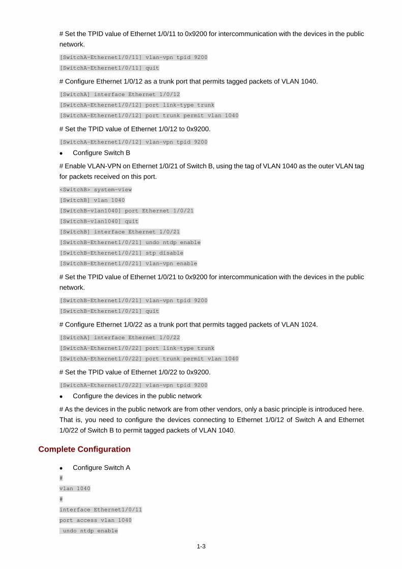
1-3
# Set the TPID value of Ethernet 1/0/11 to 0x9200 for intercommunication with the devices in the public network.
[SwitchA-Ethernet1/0/11] vlan-vpn tpid 9200
[SwitchA-Ethernet1/0/11] quit
# Configure Ethernet 1/0/12 as a trunk port that permits tagged packets of VLAN 1040.
[SwitchA] interface Ethernet 1/0/12
[SwitchA-Ethernet1/0/12] port link-type trunk
[SwitchA-Ethernet1/0/12] port trunk permit vlan 1040
# Set the TPID value of Ethernet 1/0/12 to 0x9200.
[SwitchA-Ethernet1/0/12] vlan-vpn tpid 9200
Configure Switch B
# Enable VLAN-VPN on Ethernet 1/0/21 of Switch B, using the tag of VLAN 1040 as the outer VLAN tag for packets received on this port.
<SwitchB> system-view
[SwitchB] vlan 1040
[SwitchB-vlan1040] port Ethernet 1/0/21
[SwitchB-vlan1040] quit
[SwitchB] interface Ethernet 1/0/21
[SwitchB-Ethernet1/0/21] undo ntdp enable
[SwitchB-Ethernet1/0/21] stp disable
[SwitchB-Ethernet1/0/21] vlan-vpn enable
# Set the TPID value of Ethernet 1/0/21 to 0x9200 for intercommunication with the devices in the public network.
[SwitchB-Ethernet1/0/21] vlan-vpn tpid 9200
[SwitchB-Ethernet1/0/21] quit
# Configure Ethernet 1/0/22 as a trunk port that permits tagged packets of VLAN 1024.
[SwitchA] interface Ethernet 1/0/22
[SwitchA-Ethernet1/0/22] port link-type trunk
[SwitchA-Ethernet1/0/22] port trunk permit vlan 1040
# Set the TPID value of Ethernet 1/0/22 to 0x9200.
[SwitchA-Ethernet1/0/22] vlan-vpn tpid 9200
Configure the devices in the public network
# As the devices in the public network are from other vendors, only a basic principle is introduced here. That is, you need to configure the devices connecting to Ethernet 1/0/12 of Switch A and Ethernet 1/0/22 of Switch B to permit tagged packets of VLAN 1040.
Complete Configuration
Configure Switch A #
vlan 1040
#
interface Ethernet1/0/11
port access vlan 1040
undo ntdp enable
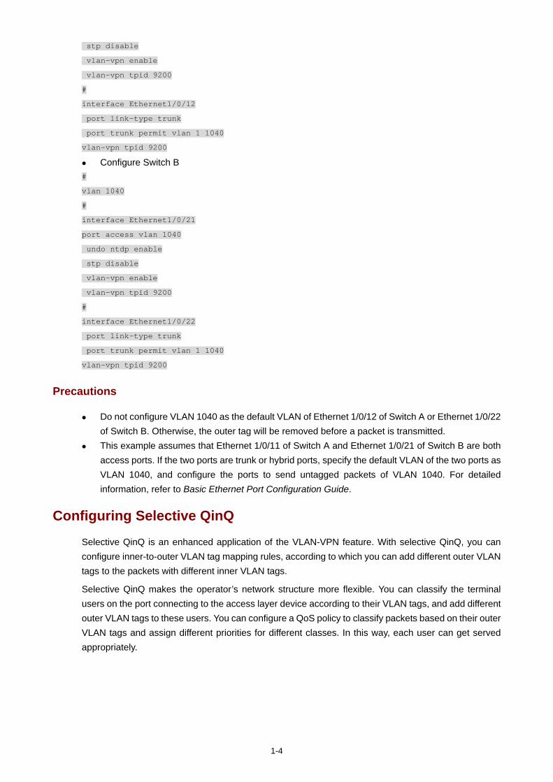
1-4
stp disable
vlan-vpn enable
vlan-vpn tpid 9200
#
interface Ethernet1/0/12
port link-type trunk
port trunk permit vlan 1 1040
vlan-vpn tpid 9200
Configure Switch B #
vlan 1040
#
interface Ethernet1/0/21
port access vlan 1040
undo ntdp enable
stp disable
vlan-vpn enable
vlan-vpn tpid 9200
#
interface Ethernet1/0/22
port link-type trunk
port trunk permit vlan 1 1040
vlan-vpn tpid 9200
Precautions
Do not configure VLAN 1040 as the default VLAN of Ethernet 1/0/12 of Switch A or Ethernet 1/0/22 of Switch B. Otherwise, the outer tag will be removed before a packet is transmitted.
This example assumes that Ethernet 1/0/11 of Switch A and Ethernet 1/0/21 of Switch B are both access ports. If the two ports are trunk or hybrid ports, specify the default VLAN of the two ports as VLAN 1040, and configure the ports to send untagged packets of VLAN 1040. For detailed information, refer to Basic Ethernet Port Configuration Guide.
Configuring Selective QinQ
Selective QinQ is an enhanced application of the VLAN-VPN feature. With selective QinQ, you can configure inner-to-outer VLAN tag mapping rules, according to which you can add different outer VLAN tags to the packets with different inner VLAN tags.
Selective QinQ makes the operator’s network structure more flexible. You can classify the terminal users on the port connecting to the access layer device according to their VLAN tags, and add different outer VLAN tags to these users. You can configure a QoS policy to classify packets based on their outer VLAN tags and assign different priorities for different classes. In this way, each user can get served appropriately.
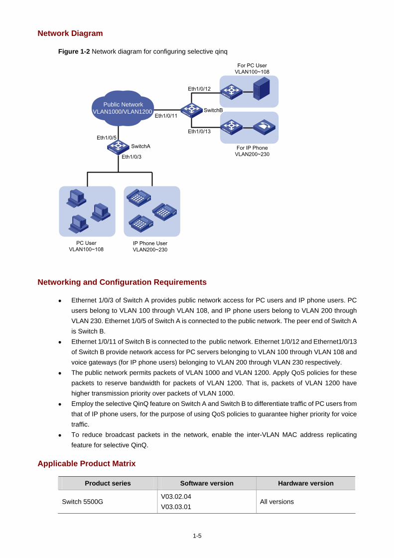
1-5
Network Diagram
Figure 1-2 Network diagram for configuring selective qinq
Public Network VLAN1000/VLAN1200
PC UserVLAN100~108
IP Phone UserVLAN200~230
Eth1/0/3
Eth1/0/5
For PC UserVLAN100~108
For IP PhoneVLAN200~230
SwitchA
SwitchBEth1/0/11
Eth1/0/12
Eth1/0/13
Networking and Configuration Requirements
Ethernet 1/0/3 of Switch A provides public network access for PC users and IP phone users. PC users belong to VLAN 100 through VLAN 108, and IP phone users belong to VLAN 200 through VLAN 230. Ethernet 1/0/5 of Switch A is connected to the public network. The peer end of Switch A is Switch B.
Ethernet 1/0/11 of Switch B is connected to the public network. Ethernet 1/0/12 and Ethernet1/0/13 of Switch B provide network access for PC servers belonging to VLAN 100 through VLAN 108 and voice gateways (for IP phone users) belonging to VLAN 200 through VLAN 230 respectively.
The public network permits packets of VLAN 1000 and VLAN 1200. Apply QoS policies for these packets to reserve bandwidth for packets of VLAN 1200. That is, packets of VLAN 1200 have higher transmission priority over packets of VLAN 1000.
Employ the selective QinQ feature on Switch A and Switch B to differentiate traffic of PC users from that of IP phone users, for the purpose of using QoS policies to guarantee higher priority for voice traffic.
To reduce broadcast packets in the network, enable the inter-VLAN MAC address replicating feature for selective QinQ.
Applicable Product Matrix
Product series Software version Hardware version
Switch 5500G V03.02.04 V03.03.01
All versions
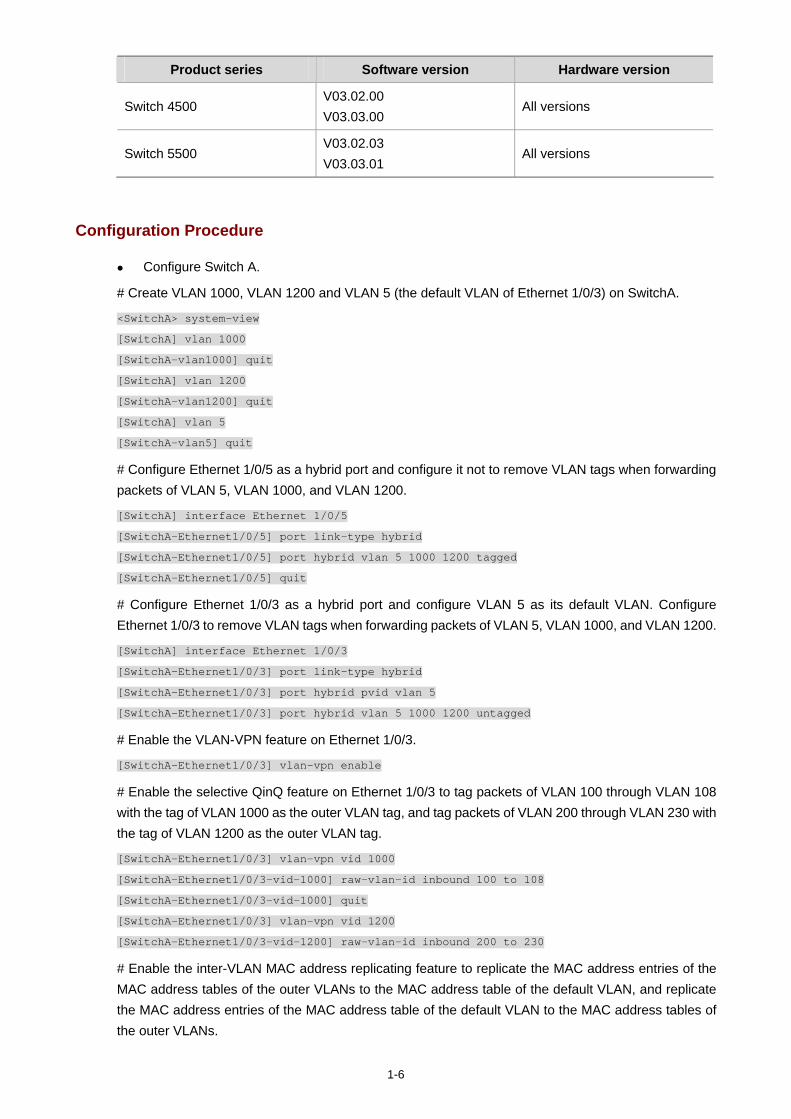
1-6
Product series Software version Hardware version
Switch 4500 V03.02.00 V03.03.00
All versions
Switch 5500 V03.02.03 V03.03.01
All versions
Configuration Procedure
Configure Switch A.
# Create VLAN 1000, VLAN 1200 and VLAN 5 (the default VLAN of Ethernet 1/0/3) on SwitchA.
<SwitchA> system-view
[SwitchA] vlan 1000
[SwitchA-vlan1000] quit
[SwitchA] vlan 1200
[SwitchA-vlan1200] quit
[SwitchA] vlan 5
[SwitchA-vlan5] quit
# Configure Ethernet 1/0/5 as a hybrid port and configure it not to remove VLAN tags when forwarding packets of VLAN 5, VLAN 1000, and VLAN 1200.
[SwitchA] interface Ethernet 1/0/5
[SwitchA-Ethernet1/0/5] port link-type hybrid
[SwitchA-Ethernet1/0/5] port hybrid vlan 5 1000 1200 tagged
[SwitchA-Ethernet1/0/5] quit
# Configure Ethernet 1/0/3 as a hybrid port and configure VLAN 5 as its default VLAN. Configure Ethernet 1/0/3 to remove VLAN tags when forwarding packets of VLAN 5, VLAN 1000, and VLAN 1200.
[SwitchA] interface Ethernet 1/0/3
[SwitchA-Ethernet1/0/3] port link-type hybrid
[SwitchA-Ethernet1/0/3] port hybrid pvid vlan 5
[SwitchA-Ethernet1/0/3] port hybrid vlan 5 1000 1200 untagged
# Enable the VLAN-VPN feature on Ethernet 1/0/3.
[SwitchA-Ethernet1/0/3] vlan-vpn enable
# Enable the selective QinQ feature on Ethernet 1/0/3 to tag packets of VLAN 100 through VLAN 108 with the tag of VLAN 1000 as the outer VLAN tag, and tag packets of VLAN 200 through VLAN 230 with the tag of VLAN 1200 as the outer VLAN tag.
[SwitchA-Ethernet1/0/3] vlan-vpn vid 1000
[SwitchA-Ethernet1/0/3-vid-1000] raw-vlan-id inbound 100 to 108
[SwitchA-Ethernet1/0/3-vid-1000] quit
[SwitchA-Ethernet1/0/3] vlan-vpn vid 1200
[SwitchA-Ethernet1/0/3-vid-1200] raw-vlan-id inbound 200 to 230
# Enable the inter-VLAN MAC address replicating feature to replicate the MAC address entries of the MAC address tables of the outer VLANs to the MAC address table of the default VLAN, and replicate the MAC address entries of the MAC address table of the default VLAN to the MAC address tables of the outer VLANs.
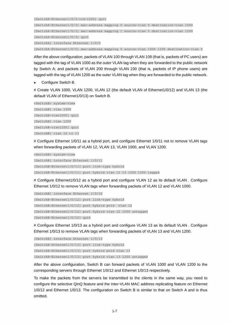
1-7
[SwitchA-Ethernet1/0/3-vid-1200] quit
[SwitchA-Ethernet1/0/3] mac-address mapping 0 source-vlan 5 destination-vlan 1000
[SwitchA-Ethernet1/0/3] mac-address mapping 1 source-vlan 5 destination-vlan 1200
[SwitchA-Ethernet1/0/3] quit
[SwitchA] interface Ethernet 1/0/5
[SwitchA-Ethernet1/0/5] mac-address mapping 0 source-vlan 1000 1200 destination-vlan 5
After the above configuration, packets of VLAN 100 through VLAN 108 (that is, packets of PC users) are tagged with the tag of VLAN 1000 as the outer VLAN tag when they are forwarded to the public network by Switch A; and packets of VLAN 200 through VLAN 230 (that is, packets of IP phone users) are tagged with the tag of VLAN 1200 as the outer VLAN tag when they are forwarded to the public network.
Configure Switch B.
# Create VLAN 1000, VLAN 1200, VLAN 12 (the default VLAN of Ethernet1/0/12) and VLAN 13 (the default VLAN of Ethernet1/0/13) on Switch B.
<SwitchB> system-view
[SwitchB] vlan 1000
[SwitchB-vlan1000] quit
[SwitchB] vlan 1200
[SwitchB-vlan1200] quit
[SwitchB] vlan 12 to 13
# Configure Ethernet 1/0/11 as a hybrid port, and configure Ethernet 1/0/11 not to remove VLAN tags when forwarding packets of VLAN 12, VLAN 13, VLAN 1000, and VLAN 1200.
<SwitchB> system-view
[SwitchB] interface Ethernet 1/0/11
[SwitchB-Ethernet1/0/11] port link-type hybrid
[SwitchB-Ethernet1/0/11] port hybrid vlan 12 13 1000 1200 tagged
# Configure Ethernet1/0/12 as a hybrid port and configure VLAN 12 as its default VLAN . Configure Ethernet 1/0/12 to remove VLAN tags when forwarding packets of VLAN 12 and VLAN 1000.
[SwitchB] interface Ethernet 1/0/12
[SwitchB-Ethernet1/0/12] port link-type hybrid
[SwitchB-Ethernet1/0/12] port hybrid pvid vlan 12
[SwitchB-Ethernet1/0/12] port hybrid vlan 12 1000 untagged
[SwitchB-Ethernet1/0/12] quit
# Configure Ethernet 1/0/13 as a hybrid port and configure VLAN 13 as its default VLAN . Configure Ethernet 1/0/13 to remove VLAN tags when forwarding packets of VLAN 13 and VLAN 1200.
[SwitchB] interface Ethernet 1/0/13
[SwitchB-Ethernet1/0/13] port link-type hybrid
[SwitchB-Ethernet1/0/13] port hybrid pvid vlan 13
[SwitchB-Ethernet1/0/13] port hybrid vlan 13 1200 untagged
After the above configuration, Switch B can forward packets of VLAN 1000 and VLAN 1200 to the corresponding servers through Ethernet 1/0/12 and Ethernet 1/0/13 respectively.
To make the packets from the servers be transmitted to the clients in the same way, you need to configure the selective QinQ feature and the inter-VLAN MAC address replicating feature on Ethernet 1/0/12 and Ethernet 1/0/13. The configuration on Switch B is similar to that on Switch A and is thus omitted.
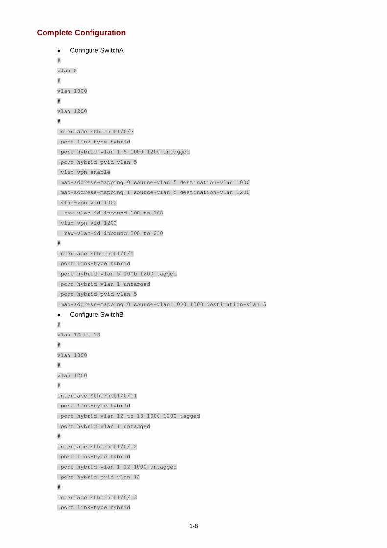
1-8
Complete Configuration
Configure SwitchA #
vlan 5
#
vlan 1000
#
vlan 1200
#
interface Ethernet1/0/3
port link-type hybrid
port hybrid vlan 1 5 1000 1200 untagged
port hybrid pvid vlan 5
vlan-vpn enable
mac-address-mapping 0 source-vlan 5 destination-vlan 1000
mac-address-mapping 1 source-vlan 5 destination-vlan 1200
vlan-vpn vid 1000
raw-vlan-id inbound 100 to 108
vlan-vpn vid 1200
raw-vlan-id inbound 200 to 230
#
interface Ethernet1/0/5
port link-type hybrid
port hybrid vlan 5 1000 1200 tagged
port hybrid vlan 1 untagged
port hybrid pvid vlan 5
mac-address-mapping 0 source-vlan 1000 1200 destination-vlan 5
Configure SwitchB #
vlan 12 to 13
#
vlan 1000
#
vlan 1200
#
interface Ethernet1/0/11
port link-type hybrid
port hybrid vlan 12 to 13 1000 1200 tagged
port hybrid vlan 1 untagged
#
interface Ethernet1/0/12
port link-type hybrid
port hybrid vlan 1 12 1000 untagged
port hybrid pvid vlan 12
#
interface Ethernet1/0/13
port link-type hybrid
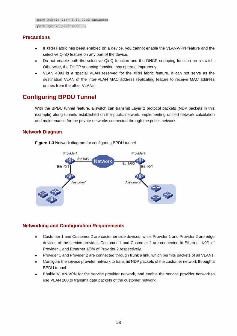
1-9
port hybrid vlan 1 13 1200 untagged
port hybrid pvid vlan 13
Precautions
If XRN Fabric has been enabled on a device, you cannot enable the VLAN-VPN feature and the selective QinQ feature on any port of the device.
Do not enable both the selective QinQ function and the DHCP snooping function on a switch. Otherwise, the DHCP snooping function may operate improperly.
VLAN 4093 is a special VLAN reserved for the XRN fabric feature. It can not serve as the destination VLAN of the inter-VLAN MAC address replicating feature to receive MAC address entries from the other VLANs.
Configuring BPDU Tunnel
With the BPDU tunnel feature, a switch can transmit Layer 2 protocol packets (NDP packets in this example) along tunnels established on the public network, implementing unified network calculation and maintenance for the private networks connected through the public network.
Network Diagram
Figure 1-3 Network diagram for configuring BPDU tunnel
NetworkEth1/0/1
Eth1/0/2Eth1/0/3
Customer1 Customer2
Provider1 Provider2
Eth1/0/4
Networking and Configuration Requirements
Customer 1 and Customer 2 are customer side devices, while Provider 1 and Provider 2 are edge devices of the service provider. Customer 1 and Customer 2 are connected to Ethernet 1/0/1 of Provider 1 and Ethernet 1/0/4 of Provider 2 respectively.
Provider 1 and Provider 2 are connected through trunk a link, which permits packets of all VLANs. Configure the service provider network to transmit NDP packets of the customer network through a
BPDU tunnel. Enable VLAN-VPN for the service provider network, and enable the service provider network to
use VLAN 100 to transmit data packets of the customer network.
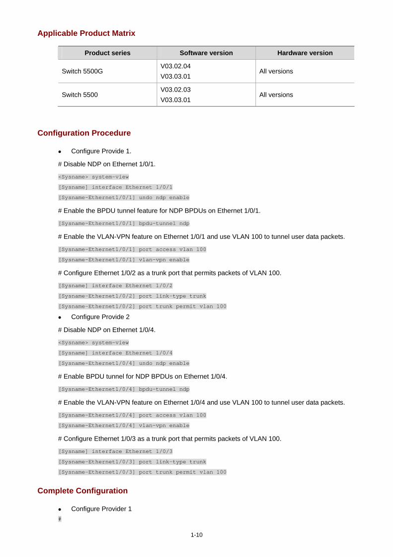
1-10
Applicable Product Matrix
Product series Software version Hardware version
Switch 5500G V03.02.04 V03.03.01
All versions
Switch 5500 V03.02.03 V03.03.01
All versions
Configuration Procedure
Configure Provide 1.
# Disable NDP on Ethernet 1/0/1.
<Sysname> system-view
[Sysname] interface Ethernet 1/0/1
[Sysname-Ethernet1/0/1] undo ndp enable
# Enable the BPDU tunnel feature for NDP BPDUs on Ethernet 1/0/1.
[Sysname-Ethernet1/0/1] bpdu-tunnel ndp
# Enable the VLAN-VPN feature on Ethernet 1/0/1 and use VLAN 100 to tunnel user data packets.
[Sysname-Ethernet1/0/1] port access vlan 100
[Sysname-Ethernet1/0/1] vlan-vpn enable
# Configure Ethernet 1/0/2 as a trunk port that permits packets of VLAN 100.
[Sysname] interface Ethernet 1/0/2
[Sysname-Ethernet1/0/2] port link-type trunk
[Sysname-Ethernet1/0/2] port trunk permit vlan 100
Configure Provide 2
# Disable NDP on Ethernet 1/0/4.
<Sysname> system-view
[Sysname] interface Ethernet 1/0/4
[Sysname-Ethernet1/0/4] undo ndp enable
# Enable BPDU tunnel for NDP BPDUs on Ethernet 1/0/4.
[Sysname-Ethernet1/0/4] bpdu-tunnel ndp
# Enable the VLAN-VPN feature on Ethernet 1/0/4 and use VLAN 100 to tunnel user data packets.
[Sysname-Ethernet1/0/4] port access vlan 100
[Sysname-Ethernet1/0/4] vlan-vpn enable
# Configure Ethernet 1/0/3 as a trunk port that permits packets of VLAN 100.
[Sysname] interface Ethernet 1/0/3
[Sysname-Ethernet1/0/3] port link-type trunk
[Sysname-Ethernet1/0/3] port trunk permit vlan 100
Complete Configuration
Configure Provider 1 #
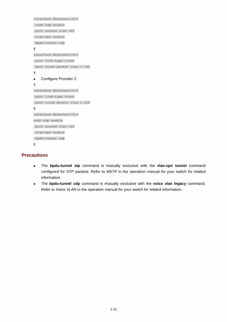
1-11
interface Ethernet1/0/1
undo ndp enable
port access vlan 100
vlan-vpn enable
bpdu-tunnel ndp
#
interface Ethernet1/0/2
port link-type trunk
port trunk permit vlan 1 100
#
Configure Provider 2 #
interface Ethernet1/0/3
port link-type trunk
port trunk permit vlan 1 100
#
interface Ethernet1/0/4
undo ndp enable
port access vlan 100
vlan-vpn enable
bpdu-tunnel ndp
#
Precautions
The bpdu-tunnel stp command is mutually exclusive with the vlan-vpn tunnel command configured for STP packets. Refer to MSTP in the operation manual for your switch for related information.
The bpdu-tunnel cdp command is mutually exclusive with the voice vlan legacy command. Refer to Voice VLAN in the operation manual for your switch for related information.

i
Table of Contents
1 Remote-ping Configuration Guide···········································································································1-1 Remote-ping Configuration ·····················································································································1-1
ICMP Test········································································································································1-1 DHCP Test ······································································································································1-3 HTTP Test ·······································································································································1-4 TCP Test (Tcpprivate Test) on the Specified Ports·········································································1-6 DNS Test ·········································································································································1-8
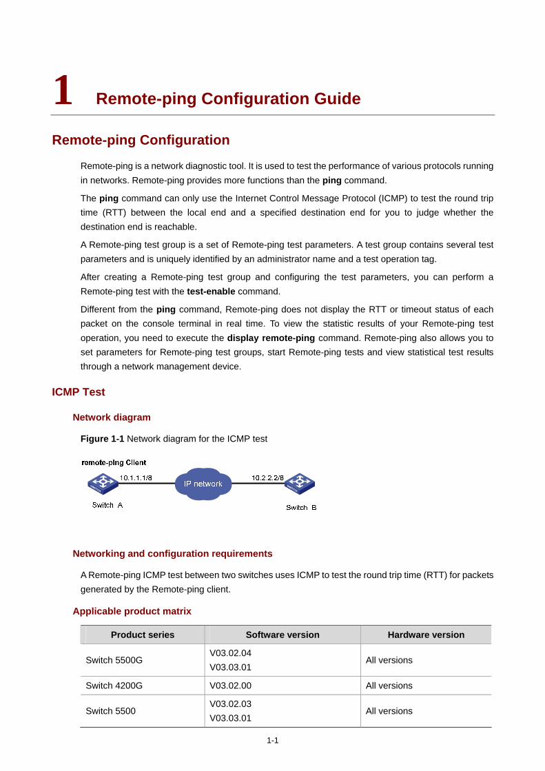
1-1
1 Remote-ping Configuration Guide
Remote-ping Configuration
Remote-ping is a network diagnostic tool. It is used to test the performance of various protocols running in networks. Remote-ping provides more functions than the ping command.
The ping command can only use the Internet Control Message Protocol (ICMP) to test the round trip time (RTT) between the local end and a specified destination end for you to judge whether the destination end is reachable.
A Remote-ping test group is a set of Remote-ping test parameters. A test group contains several test parameters and is uniquely identified by an administrator name and a test operation tag.
After creating a Remote-ping test group and configuring the test parameters, you can perform a Remote-ping test with the test-enable command.
Different from the ping command, Remote-ping does not display the RTT or timeout status of each packet on the console terminal in real time. To view the statistic results of your Remote-ping test operation, you need to execute the display remote-ping command. Remote-ping also allows you to set parameters for Remote-ping test groups, start Remote-ping tests and view statistical test results through a network management device.
ICMP Test
Network diagram
Figure 1-1 Network diagram for the ICMP test
Networking and configuration requirements
A Remote-ping ICMP test between two switches uses ICMP to test the round trip time (RTT) for packets generated by the Remote-ping client.
Applicable product matrix
Product series Software version Hardware version
Switch 5500G V03.02.04 V03.03.01
All versions
Switch 4200G V03.02.00 All versions
Switch 5500 V03.02.03 V03.03.01
All versions
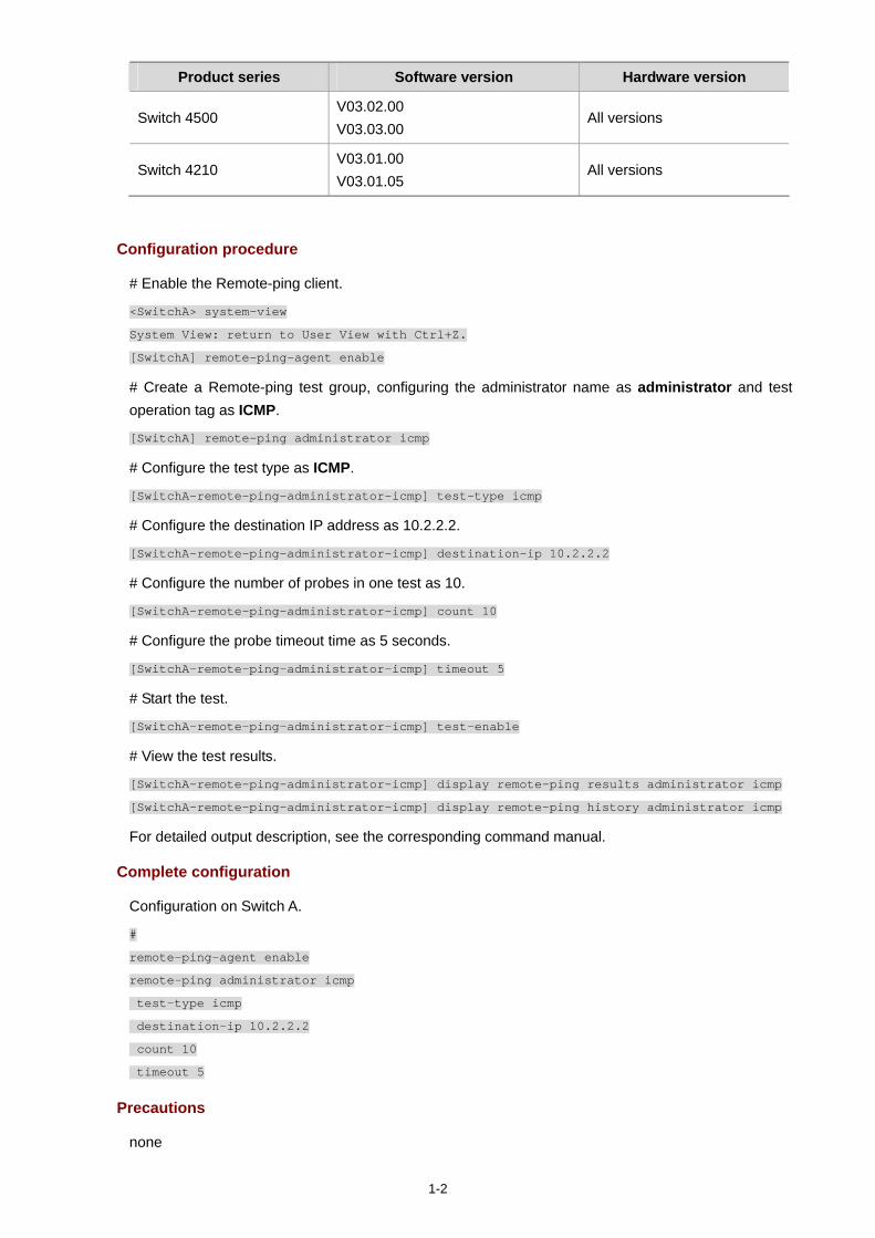
1-2
Product series Software version Hardware version
Switch 4500 V03.02.00 V03.03.00
All versions
Switch 4210 V03.01.00 V03.01.05
All versions
Configuration procedure
# Enable the Remote-ping client.
<SwitchA> system-view
System View: return to User View with Ctrl+Z.
[SwitchA] remote-ping-agent enable
# Create a Remote-ping test group, configuring the administrator name as administrator and test operation tag as ICMP.
[SwitchA] remote-ping administrator icmp
# Configure the test type as ICMP.
[SwitchA-remote-ping-administrator-icmp] test-type icmp
# Configure the destination IP address as 10.2.2.2.
[SwitchA-remote-ping-administrator-icmp] destination-ip 10.2.2.2
# Configure the number of probes in one test as 10.
[SwitchA-remote-ping-administrator-icmp] count 10
# Configure the probe timeout time as 5 seconds.
[SwitchA-remote-ping-administrator-icmp] timeout 5
# Start the test.
[SwitchA-remote-ping-administrator-icmp] test-enable
# View the test results.
[SwitchA-remote-ping-administrator-icmp] display remote-ping results administrator icmp
[SwitchA-remote-ping-administrator-icmp] display remote-ping history administrator icmp
For detailed output description, see the corresponding command manual.
Complete configuration
Configuration on Switch A.
#
remote-ping-agent enable
remote-ping administrator icmp
test-type icmp
destination-ip 10.2.2.2
count 10
timeout 5
Precautions
none
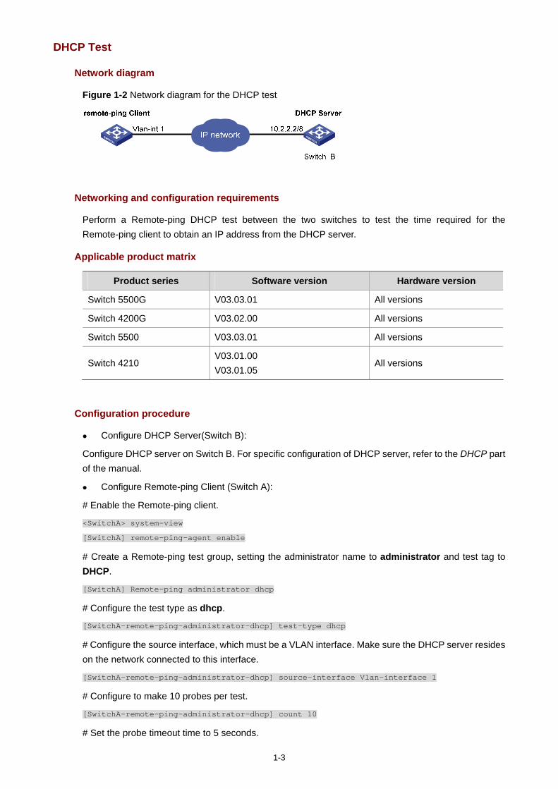
1-3
DHCP Test
Network diagram
Figure 1-2 Network diagram for the DHCP test
Networking and configuration requirements
Perform a Remote-ping DHCP test between the two switches to test the time required for the Remote-ping client to obtain an IP address from the DHCP server.
Applicable product matrix
Product series Software version Hardware version
Switch 5500G V03.03.01 All versions
Switch 4200G V03.02.00 All versions
Switch 5500 V03.03.01 All versions
Switch 4210 V03.01.00 V03.01.05
All versions
Configuration procedure
Configure DHCP Server(Switch B):
Configure DHCP server on Switch B. For specific configuration of DHCP server, refer to the DHCP part of the manual.
Configure Remote-ping Client (Switch A):
# Enable the Remote-ping client.
<SwitchA> system-view
[SwitchA] remote-ping-agent enable
# Create a Remote-ping test group, setting the administrator name to administrator and test tag to DHCP.
[SwitchA] Remote-ping administrator dhcp
# Configure the test type as dhcp.
[SwitchA-remote-ping-administrator-dhcp] test-type dhcp
# Configure the source interface, which must be a VLAN interface. Make sure the DHCP server resides on the network connected to this interface.
[SwitchA-remote-ping-administrator-dhcp] source-interface Vlan-interface 1
# Configure to make 10 probes per test.
[SwitchA-remote-ping-administrator-dhcp] count 10
# Set the probe timeout time to 5 seconds.
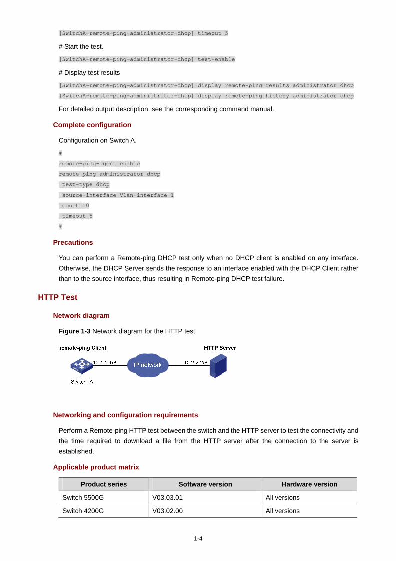
1-4
[SwitchA-remote-ping-administrator-dhcp] timeout 5
# Start the test.
[SwitchA-remote-ping-administrator-dhcp] test-enable
# Display test results
[SwitchA-remote-ping-administrator-dhcp] display remote-ping results administrator dhcp
[SwitchA-remote-ping-administrator-dhcp] display remote-ping history administrator dhcp
For detailed output description, see the corresponding command manual.
Complete configuration
Configuration on Switch A.
#
remote-ping-agent enable
remote-ping administrator dhcp
test-type dhcp
source-interface Vlan-interface 1
count 10
timeout 5
#
Precautions
You can perform a Remote-ping DHCP test only when no DHCP client is enabled on any interface. Otherwise, the DHCP Server sends the response to an interface enabled with the DHCP Client rather than to the source interface, thus resulting in Remote-ping DHCP test failure.
HTTP Test
Network diagram
Figure 1-3 Network diagram for the HTTP test
Networking and configuration requirements
Perform a Remote-ping HTTP test between the switch and the HTTP server to test the connectivity and the time required to download a file from the HTTP server after the connection to the server is established.
Applicable product matrix
Product series Software version Hardware version
Switch 5500G V03.03.01 All versions
Switch 4200G V03.02.00 All versions
1-5
Product series Software version Hardware version
Switch 5500 V03.03.01 All versions
Switch 4210 V03.01.00 V03.01.05
All versions
Configuration procedure
Configure HTTP Server:
Use Windows 2003 Server as the HTTP server. For HTTP server configuration, refer to the related instruction on Windows 2003 Server configuration.
Configure Remote-ping Client (Switch A):
# Enable the Remote-ping client.
<SwitchA> system-view
[SwitchA] remote-ping-agent enable
# Create a Remote-ping test group, setting the administrator name to administrator and test tag to HTTP.
[SwitchA] Remote-ping administrator http
# Configure the test type as http.
[SwitchA-remote-ping-administrator-http] test-type http
# Configure the IP address of the HTTP server as 10.2.2.2.
[SwitchA-remote-ping-administrator-http] destination-ip 10.2.2.2
# Configure to make 10 probes per test.
[SwitchA-remote-ping-administrator-http] count 10
# Set the probe timeout time to 30 seconds.
[SwitchA-remote-ping-administrator-http] timeout 30
# Start the test.
[SwitchA-remote-ping-administrator-http] test-enable
# Display test results
[SwitchA-remote-ping-administrator-http] display remote-ping results administrator http
[SwitchA-remote-ping-administrator-http] display remote-ping history administrator http
For detailed output description, see the corresponding command manual.
Complete configuration
Configuration on Switch A.
#
remote-ping-agent enable
remote-ping administrator http
test-type http
destination-ip 10.2.2.2
count 10
timeout 30
#
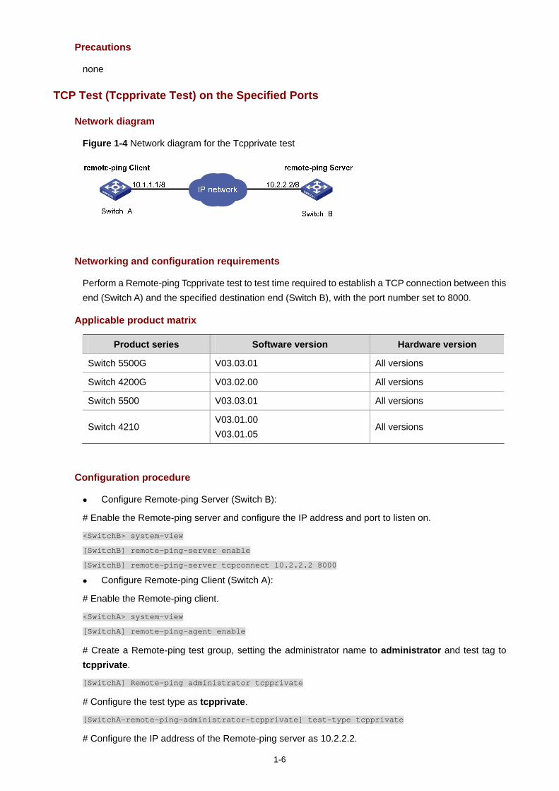
1-6
Precautions
none
TCP Test (Tcpprivate Test) on the Specified Ports
Network diagram
Figure 1-4 Network diagram for the Tcpprivate test
Networking and configuration requirements
Perform a Remote-ping Tcpprivate test to test time required to establish a TCP connection between this end (Switch A) and the specified destination end (Switch B), with the port number set to 8000.
Applicable product matrix
Product series Software version Hardware version
Switch 5500G V03.03.01 All versions
Switch 4200G V03.02.00 All versions
Switch 5500 V03.03.01 All versions
Switch 4210 V03.01.00 V03.01.05
All versions
Configuration procedure
Configure Remote-ping Server (Switch B):
# Enable the Remote-ping server and configure the IP address and port to listen on.
<SwitchB> system-view
[SwitchB] remote-ping-server enable
[SwitchB] remote-ping-server tcpconnect 10.2.2.2 8000
Configure Remote-ping Client (Switch A):
# Enable the Remote-ping client.
<SwitchA> system-view
[SwitchA] remote-ping-agent enable
# Create a Remote-ping test group, setting the administrator name to administrator and test tag to tcpprivate.
[SwitchA] Remote-ping administrator tcpprivate
# Configure the test type as tcpprivate.
[SwitchA-remote-ping-administrator-tcpprivate] test-type tcpprivate
# Configure the IP address of the Remote-ping server as 10.2.2.2.
1-7
[SwitchA-remote-ping-administrator-tcpprivate] destination-ip 10.2.2.2
# Configure the destination port on the Remote-ping server.
[SwitchA-remote-ping-administrator-tcpprivate] destination-port 8000
# Configure to make 10 probes per test.
[SwitchA-remote-ping-administrator-tcpprivate] count 10
# Set the probe timeout time to 5 seconds.
[SwitchA-remote-ping-administrator-tcpprivate] timeout 5
# Start the test.
[SwitchA-remote-ping-administrator-tcpprivate] test-enable
# Display test results.
[SwitchA-remote-ping-administrator-tcpprivate] display remote-ping results administrator
tcpprivate
[SwitchA-remote-ping-administrator-tcpprivate] display remote-ping history administrator
tcpprivate
For detailed output description, see the corresponding command manual.
Complete configuration
Configuration on Switch B. #
remote-ping-server enable
remote-ping-server tcpconnect 10.2.2.2 8000
#
Configuration on Switch A. #
remote-ping-agent enable
remote-ping administrator tcpprivate
test-type tcpprivate
destination-ip 10.2.2.2
destination-port 8000
count 10
timeout 5
#
Precautions
none
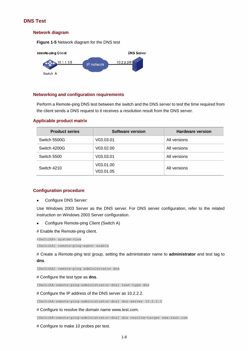
1-8
DNS Test
Network diagram
Figure 1-5 Network diagram for the DNS test
Networking and configuration requirements
Perform a Remote-ping DNS test between the switch and the DNS server to test the time required from the client sends a DNS request to it receives a resolution result from the DNS server.
Applicable product matrix
Product series Software version Hardware version
Switch 5500G V03.03.01 All versions
Switch 4200G V03.02.00 All versions
Switch 5500 V03.03.01 All versions
Switch 4210 V03.01.00 V03.01.05
All versions
Configuration procedure
Configure DNS Server:
Use Windows 2003 Server as the DNS server. For DNS server configuration, refer to the related instruction on Windows 2003 Server configuration.
Configure Remote-ping Client (Switch A)
# Enable the Remote-ping client.
<SwitchA> system-view
[SwitchA] remote-ping-agent enable
# Create a Remote-ping test group, setting the administrator name to administrator and test tag to dns.
[SwitchA] remote-ping administrator dns
# Configure the test type as dns.
[SwitchA-remote-ping-administrator-dns] test-type dns
# Configure the IP address of the DNS server as 10.2.2.2.
[SwitchA-remote-ping-administrator-dns] dns-server 10.2.2.2
# Configure to resolve the domain name www.test.com.
[SwitchA-remote-ping-administrator-dns] dns resolve-target www.test.com
# Configure to make 10 probes per test.
1-9
[SwitchA-remote-ping-administrator-dns] count 10
# Set the probe timeout time to 5 seconds.
[SwitchA-remote-ping-administrator-dns] timeout 5
# Start the test.
[SwitchA-remote-ping-administrator-dns] test-enable
# Display test results.
[SwitchA-remote-ping-administrator-dns] display remote-ping results administrator dns
[SwitchA-remote-ping-administrator-dns] display remote-ping history administrator dns
For detailed output description, see the corresponding command manual.
Complete configuration
Configuration on Switch A. #
remote-ping-agent enable
remote-ping administrator dns
test-type dns
destination-ip 10.2.2.2
dns resolve-target www.test.com
count 10
timeout 5
#
Precautions
None
i
Table of Contents
1 DNS Configuration Guide ·························································································································1-1 Static Domain Name Resolution Configuration Guide············································································1-1
Network Diagram·····························································································································1-1 Networking and Configuration Requirements··················································································1-1 Applicable Product Matrix················································································································1-1 Configuration Procedure··················································································································1-1 Complete Configuration···················································································································1-2 Precautions······································································································································1-2
Dynamic Domain Name Resolution Configuration Guide·······································································1-2 Network Diagram·····························································································································1-2 Networking and Configuration Requirements··················································································1-2 Applicable Product Matrix················································································································1-3 Configuration Procedure··················································································································1-3 Complete Configuration···················································································································1-3 Precautions······································································································································1-4
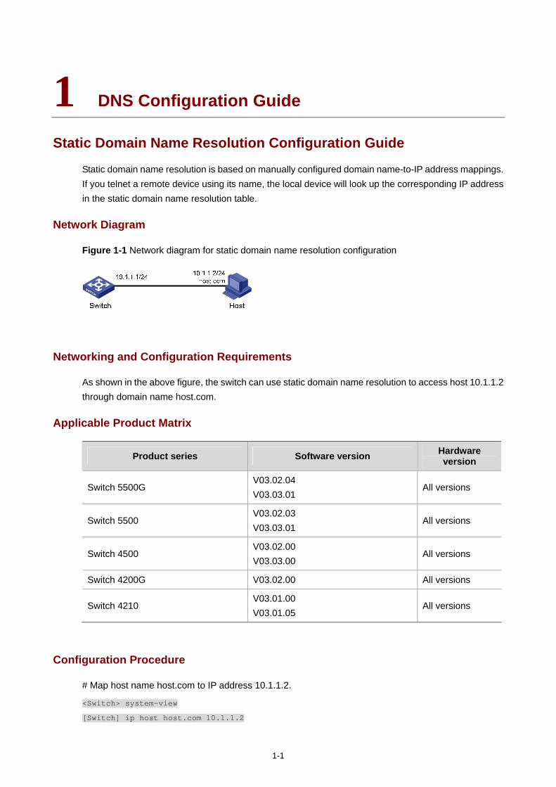
1-1
1 DNS Configuration Guide
Static Domain Name Resolution Configuration Guide
Static domain name resolution is based on manually configured domain name-to-IP address mappings. If you telnet a remote device using its name, the local device will look up the corresponding IP address in the static domain name resolution table.
Network Diagram
Figure 1-1 Network diagram for static domain name resolution configuration
Networking and Configuration Requirements
As shown in the above figure, the switch can use static domain name resolution to access host 10.1.1.2 through domain name host.com.
Applicable Product Matrix
Product series Software version Hardware version
Switch 5500G V03.02.04 V03.03.01
All versions
Switch 5500 V03.02.03 V03.03.01
All versions
Switch 4500 V03.02.00 V03.03.00
All versions
Switch 4200G V03.02.00 All versions
Switch 4210 V03.01.00 V03.01.05
All versions
Configuration Procedure
# Map host name host.com to IP address 10.1.1.2.
<Switch> system-view
[Switch] ip host host.com 10.1.1.2
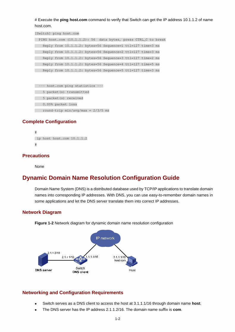
1-2
# Execute the ping host.com command to verify that Switch can get the IP address 10.1.1.2 of name host.com.
[Switch] ping host.com
PING host.com (10.1.1.2): 56 data bytes, press CTRL_C to break
Reply from 10.1.1.2: bytes=56 Sequence=1 ttl=127 time=3 ms
Reply from 10.1.1.2: bytes=56 Sequence=2 ttl=127 time=3 ms
Reply from 10.1.1.2: bytes=56 Sequence=3 ttl=127 time=2 ms
Reply from 10.1.1.2: bytes=56 Sequence=4 ttl=127 time=5 ms
Reply from 10.1.1.2: bytes=56 Sequence=5 ttl=127 time=3 ms
--- host.com ping statistics ---
5 packet(s) transmitted
5 packet(s) received
0.00% packet loss
round-trip min/avg/max = 2/3/5 ms
Complete Configuration
#
ip host host.com 10.1.1.2
#
Precautions
None
Dynamic Domain Name Resolution Configuration Guide
Domain Name System (DNS) is a distributed database used by TCP/IP applications to translate domain names into corresponding IP addresses. With DNS, you can use easy-to-remember domain names in some applications and let the DNS server translate them into correct IP addresses.
Network Diagram
Figure 1-2 Network diagram for dynamic domain name resolution configuration
Networking and Configuration Requirements
Switch serves as a DNS client to access the host at 3.1.1.1/16 through domain name host. The DNS server has the IP address 2.1.1.2/16. The domain name suffix is com.
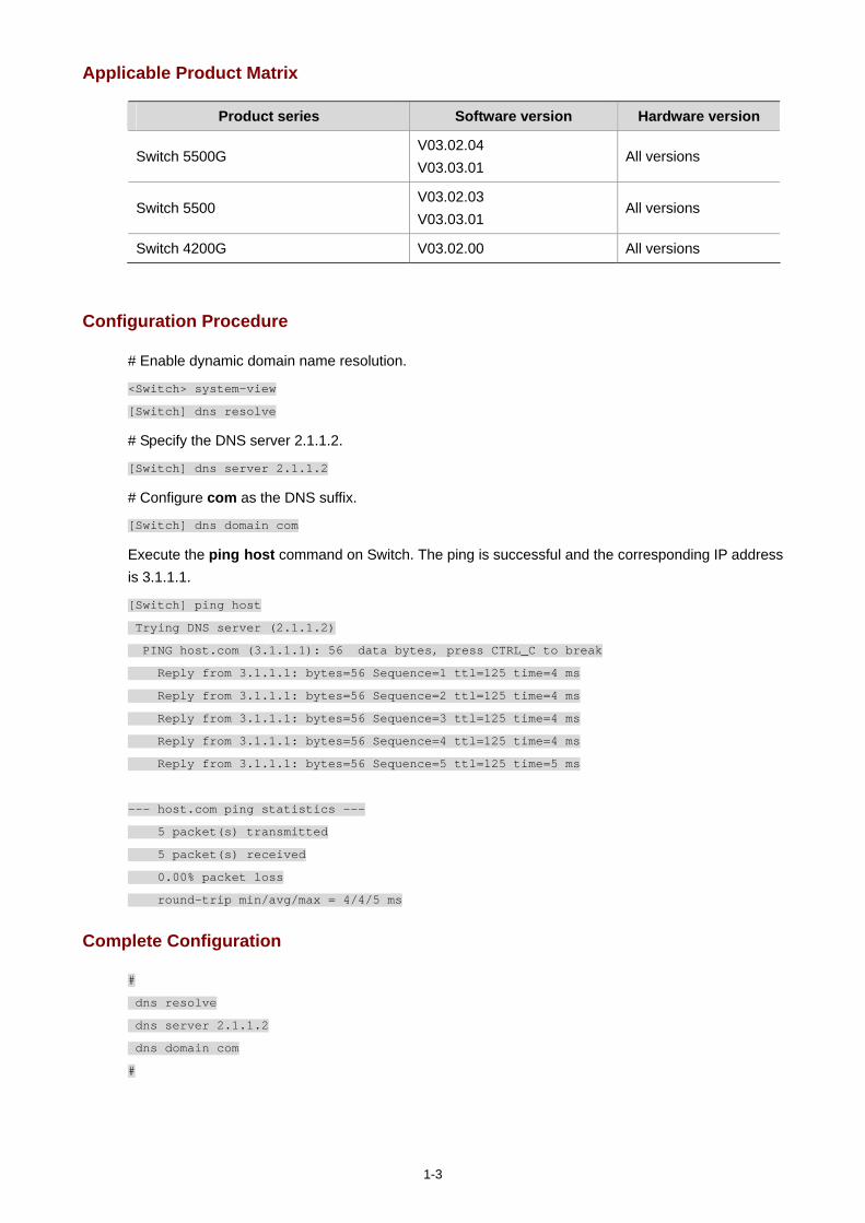
1-3
Applicable Product Matrix
Product series Software version Hardware version
Switch 5500G V03.02.04 V03.03.01
All versions
Switch 5500 V03.02.03 V03.03.01
All versions
Switch 4200G V03.02.00 All versions
Configuration Procedure
# Enable dynamic domain name resolution.
<Switch> system-view
[Switch] dns resolve
# Specify the DNS server 2.1.1.2.
[Switch] dns server 2.1.1.2
# Configure com as the DNS suffix.
[Switch] dns domain com
Execute the ping host command on Switch. The ping is successful and the corresponding IP address is 3.1.1.1.
[Switch] ping host
Trying DNS server (2.1.1.2)
PING host.com (3.1.1.1): 56 data bytes, press CTRL_C to break
Reply from 3.1.1.1: bytes=56 Sequence=1 ttl=125 time=4 ms
Reply from 3.1.1.1: bytes=56 Sequence=2 ttl=125 time=4 ms
Reply from 3.1.1.1: bytes=56 Sequence=3 ttl=125 time=4 ms
Reply from 3.1.1.1: bytes=56 Sequence=4 ttl=125 time=4 ms
Reply from 3.1.1.1: bytes=56 Sequence=5 ttl=125 time=5 ms
--- host.com ping statistics ---
5 packet(s) transmitted
5 packet(s) received
0.00% packet loss
round-trip min/avg/max = 4/4/5 ms
Complete Configuration
#
dns resolve
dns server 2.1.1.2
dns domain com
#

1-4
Precautions
The routes between the DNS server, Switch, and Host are reachable. Necessary configurations are done on the devices.
There is a mapping between domain name host and IP address 3.1.1.1/16 on the DNS server.
i
Table of Contents
1 Access Management Configuration Guide ·····························································································1-1 Configuring Access Management ···········································································································1-1
Network Diagram·····························································································································1-1 Networking and Configuration Requirements··················································································1-1 Applicable Product Matrix················································································································1-2 Configuration Procedure··················································································································1-2 Complete Configuration···················································································································1-2 Precautions······································································································································1-2
Configuring Access Management with Port Isolation ·············································································1-3 Network Diagram·····························································································································1-3 Networking and Configuration Requirements··················································································1-3 Applicable Product Matrix················································································································1-3 Configuration Procedure··················································································································1-3 Complete Configuration···················································································································1-4 Precautions······································································································································1-4
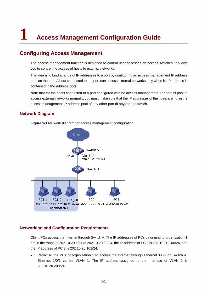
1-1
1 Access Management Configuration Guide
Configuring Access Management
The access management function is designed to control user accesses on access switches. It allows you to control the access of hosts to external networks.
The idea is to bind a range of IP addresses to a port by configuring an access management IP address pool on the port. A host connected to the port can access external networks only when its IP address is contained in the address pool.
Note that for the hosts connected to a port configured with no access management IP address pool to access external networks normally, you must make sure that the IP addresses of the hosts are not in the access management IP address pool of any other port (if any) on the switch.
Network Diagram
Figure 1-1 Network diagram for access management configuration
Networking and Configuration Requirements
Client PCs access the Internet through Switch A. The IP addresses of PCs belonging to organization 1 are in the range of 202.10.20.1/24 to 202.10.20.20/24, the IP address of PC 2 is 202.10.20.100/24, and the IP address of PC 3 is 202.10.20.101/24.
Permit all the PCs of organization 1 to access the Internet through Ethernet 1/0/1 on Switch A. Ethernet 1/0/1 carries VLAN 1. The IP address assigned to the interface of VLAN 1 is 202.10.20.200/24.
1-2
PCs that do not belong to organization 1, such as PC 2 and PC 3, are not allowed to access the Internet through Ethernet 1/0/1 on Switch A.
Applicable Product Matrix
Product series Software version Hardware version
Switch 5500G V03.02.04 V03.03.01
All versions
Switch 5500 V03.02.03 V03.03.01
All versions
Configuration Procedure
# Enable access management on Switch A.
[SwitchA] am enable
# Configure the IP address of VLAN-interface 1 as 202.10.20.200/24.
[SwitchA] interface Vlan-interface 1
[SwitchA-Vlan-interface1] ip address 202.10.20.200 24
[SwitchA-Vlan-interface1] quit
# Configure an access management IP address pool for Ethernet 1/0/1.
[SwitchA] interface Ethernet 1/0/1
[SwitchA-Ethernet1/0/1] am ip-pool 202.10.20.1 20
Complete Configuration
#
am enable
#
interface Vlan-interface1
ip address 202.10.20.200 255.255.255.0
#
interface Ethernet1/0/1
am ip-pool 202.10.20.1 20
#
Precautions
The IP addresses in the access management IP address pool configured for a port must be on the same segment as the VLAN-interface IP address of the VLAN to which the port belongs.
If the access management IP address pool to be configured for a port contains an IP address in a static ARP entry of another port, the system will ask you to delete the ARP entry to ensure that the access management IP address pool can take effect.
To allow only the hosts bound with a port and with their IP addresses in the access management IP address pool of the port to access external networks, configure static ARP entries only for IP addresses in the address pool.
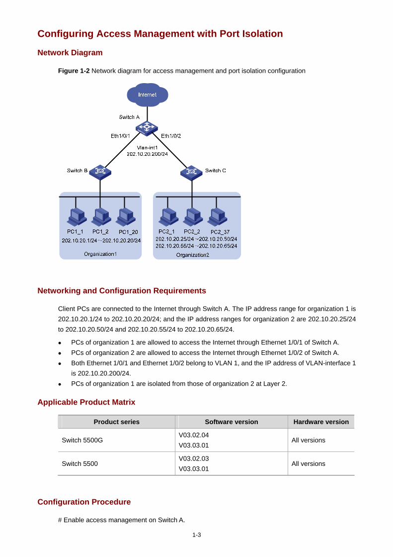
1-3
Configuring Access Management with Port Isolation
Network Diagram
Figure 1-2 Network diagram for access management and port isolation configuration
Networking and Configuration Requirements
Client PCs are connected to the Internet through Switch A. The IP address range for organization 1 is 202.10.20.1/24 to 202.10.20.20/24; and the IP address ranges for organization 2 are 202.10.20.25/24 to 202.10.20.50/24 and 202.10.20.55/24 to 202.10.20.65/24.
PCs of organization 1 are allowed to access the Internet through Ethernet 1/0/1 of Switch A. PCs of organization 2 are allowed to access the Internet through Ethernet 1/0/2 of Switch A. Both Ethernet 1/0/1 and Ethernet 1/0/2 belong to VLAN 1, and the IP address of VLAN-interface 1
is 202.10.20.200/24. PCs of organization 1 are isolated from those of organization 2 at Layer 2.
Applicable Product Matrix
Product series Software version Hardware version
Switch 5500G V03.02.04 V03.03.01
All versions
Switch 5500 V03.02.03 V03.03.01
All versions
Configuration Procedure
# Enable access management on Switch A.
1-4
[SwitchA] am enable
# Configure the IP address of VLAN-interface 1 as 202.10.20.200/24.
[SwitchA] interface Vlan-interface 1
[SwitchA-Vlan-interface1] ip address 202.10.20.200 24
[SwitchA-Vlan-interface1] quit
# Configure an access management IP address pool for Ethernet 1/0/1.
[SwitchA] interface Ethernet 1/0/1
[SwitchA-Ethernet1/0/1] am ip-pool 202.10.20.1 20
# Add Ethernet 1/0/1 to the isolation group.
[SwitchA-Ethernet1/0/1] port isolate
[SwitchA-Ethernet1/0/1] quit
# Configure an access management IP address pool for Ethernet 1/0/2.
[SwitchA] interface Ethernet 1/0/2
[SwitchA-Ethernet1/0/2] am ip-pool 202.10.20.25 26 202.10.20.55 11
# Add Ethernet 1/0/2 to the isolation group.
[SwitchA-Ethernet1/0/2] port isolate
[SwitchA-Ethernet1/0/2] quit
Complete Configuration
#
am enable
#
interface Vlan-interface1
ip address 202.10.20.200 255.255.255.0
#
interface Ethernet1/0/1
port isolate
am ip-pool 202.10.20.1 20
#
interface Ethernet1/0/2
port isolate
am ip-pool 202.10.20.25 26 202.10.20.55 11
#
Precautions
Refer to section Precautions for details.

i
Table of Contents
1 Web Authentication Configuration Guide·······························································································1-1 Configuring Web Authentication ·············································································································1-1
Network Diagram·····························································································································1-1 Networking and Configuration Requirements··················································································1-1 Applicable Product Matrix················································································································1-1 Configuration Procedure··················································································································1-2 Complete Configuration···················································································································1-3 Precautions······································································································································1-3
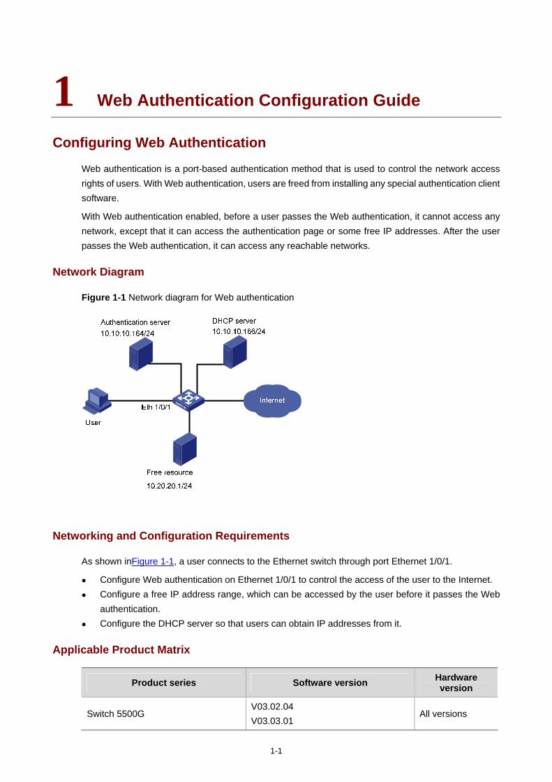
1-1
1 Web Authentication Configuration Guide
Configuring Web Authentication
Web authentication is a port-based authentication method that is used to control the network access rights of users. With Web authentication, users are freed from installing any special authentication client software.
With Web authentication enabled, before a user passes the Web authentication, it cannot access any network, except that it can access the authentication page or some free IP addresses. After the user passes the Web authentication, it can access any reachable networks.
Network Diagram
Figure 1-1 Network diagram for Web authentication
Networking and Configuration Requirements
As shown inFigure 1-1, a user connects to the Ethernet switch through port Ethernet 1/0/1.
Configure Web authentication on Ethernet 1/0/1 to control the access of the user to the Internet. Configure a free IP address range, which can be accessed by the user before it passes the Web
authentication. Configure the DHCP server so that users can obtain IP addresses from it.
Applicable Product Matrix
Product series Software version Hardware version
Switch 5500G V03.02.04 V03.03.01
All versions
1-2
Product series Software version Hardware version
Switch 5500 V03.02.03 V03.03.01
All versions
Configuration Procedure
# Perform DHCP-related configuration on the DHCP server. (It is assumed that the user will automatically obtain an IP address through the DHCP server.)
# Set the IP address and port number of the Web authentication server.
<Sysname> system-view
[Sysname] web-authentication web-server ip 10.10.10.10 port 8080
# Configure a free IP address range, so that the user can access free resources before it passes the Web authentication.
[Sysname] web-authentication free-ip 10.20.20.1 24
# Enable Web authentication on Ethernet 1/0/1 and set the user access method to designated.
[Sysname] interface Ethernet 1/0/1
[Sysname-Ethernet1/0/1] web-authentication select method designated
# Create RADIUS scheme radius1 and enter its view.
[Sysname] radius scheme radius1
# Set the IP address of the primary RADIUS authentication server.
[Sysname-radius-radius1] primary authentication 10.10.10.164
# Enable accounting optional.
[Sysname-radius-radius1] accounting optional
# Set the password that will be used to encrypt the messages exchanged between the switch and the RADIUS authentication server.
[Sysname -radius-radius1] key authentication expert
# Configure the system to strip domain name off a user name before transmitting the user name to the RADIUS server.
[Sysname-radius-radius1] user-name-format without-domain
[Sysname-radius-radius1] quit
# Create ISP domain aabbcc.net for Web authentication users and enter the domain view.
[Sysname] domain aabbcc.net
# Configure domain aabbcc.net as the default user domain.
[Sysname] domain default enable aabbcc.net
# Reference scheme radius1 in domain aabbcc.net.
[Sysname-isp-aabbcc.net] scheme radius-scheme radius1
# Enable Web authentication globally. (It is recommended to take this step as the last step, so as to avoid the case that a valid user cannot access the network due to that some other related configurations are not finished.)
1-3
[Sysname] web-authentication enable
Now, Web authentication takes effect. Before the user passes the Web authentication, it cannot access external networks and can only access the free resource.
The user can perform the following steps to access the Internet:
Step 1: Enter http://10.10.10.10:8080 in the address column of IE. A page with the following prompt will be displayed: ”Please input your name and the password!”.
Step 2: Enter the correct user name and password and then click [login]. The following page will be displayed: ”Authentication passed!”.
Now the user can access external networks.
Complete Configuration
#
web-authentication web-server ip 10.10.10.10 port 8080
#
domain default enable aabbcc.net
#
web-authentication web-server ip 10.10.10.10 port 8080
web-authentication free-ip 10.20.20.0 255.255.255.0
web-authentication enable
#
radius scheme radius1
primary authentication 10.10.10.164
accounting optional
key authentication expert
user-name-format without-domain
#
domain aabbcc.net
scheme radius-scheme radius1
#
interface Ethernet1/0/1
web-authentication select method designated
#
Precautions
Before enabling global Web authentication, you should first set the IP address of a Web authentication server.
Web authentication cannot be enabled when one of the following features is enabled, and vice versa: 802.1x, MAC authentication, port security, port aggregation and XRN.
You can make Web authentication settings on individual ports before Web authentication is enabled globally, but they will not take effect. The Web authentication settings on ports take effect immediately once you enable Web authentication globally.
A Web authentication client and the switch with Web authentication enabled must be able to communicate at the network layer so that the Web authentication page can be displayed on the Web authentication client.

1-4
Web authentication is mutually exclusive with functions that depend on ACLs such as IP filtering, ARP intrusion detection, QoS, and port binding.
After a user gets online in shared access method, if you configure an authentication-free user whose IP address and MAC address are the same as those of the online user, the online user will be forced to get offline.

i
Table of Contents
1 IPv6 Management Configuring Guide······································································································1-1 Configuring IPv6······································································································································1-1
Network Diagram·····························································································································1-1 Networking and Configuration Requirements··················································································1-1 Applicable Product Matrix················································································································1-1 Configuration Procedure··················································································································1-2 Complete Configuration···················································································································1-3 Precautions······································································································································1-3
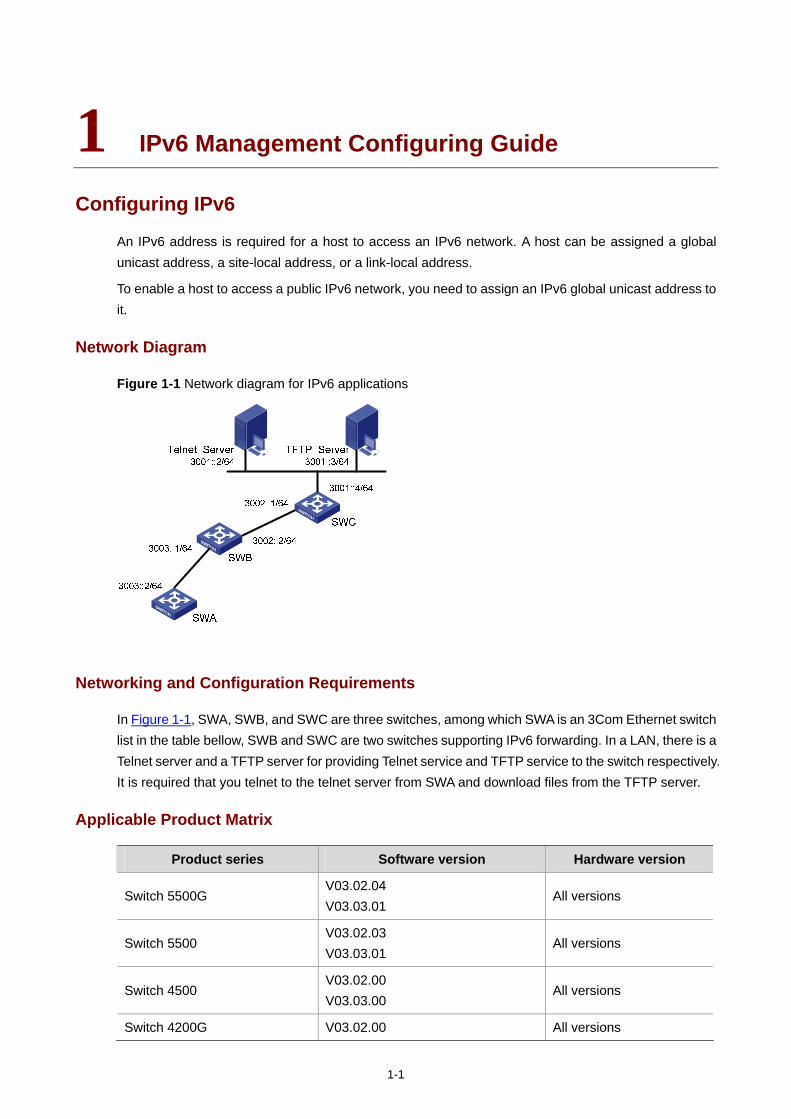
1-1
1 IPv6 Management Configuring Guide
Configuring IPv6
An IPv6 address is required for a host to access an IPv6 network. A host can be assigned a global unicast address, a site-local address, or a link-local address.
To enable a host to access a public IPv6 network, you need to assign an IPv6 global unicast address to it.
Network Diagram
Figure 1-1 Network diagram for IPv6 applications
Networking and Configuration Requirements
In Figure 1-1, SWA, SWB, and SWC are three switches, among which SWA is an 3Com Ethernet switch list in the table bellow, SWB and SWC are two switches supporting IPv6 forwarding. In a LAN, there is a Telnet server and a TFTP server for providing Telnet service and TFTP service to the switch respectively. It is required that you telnet to the telnet server from SWA and download files from the TFTP server.
Applicable Product Matrix
Product series Software version Hardware version
Switch 5500G V03.02.04 V03.03.01
All versions
Switch 5500 V03.02.03 V03.03.01
All versions
Switch 4500 V03.02.00 V03.03.00
All versions
Switch 4200G V03.02.00 All versions
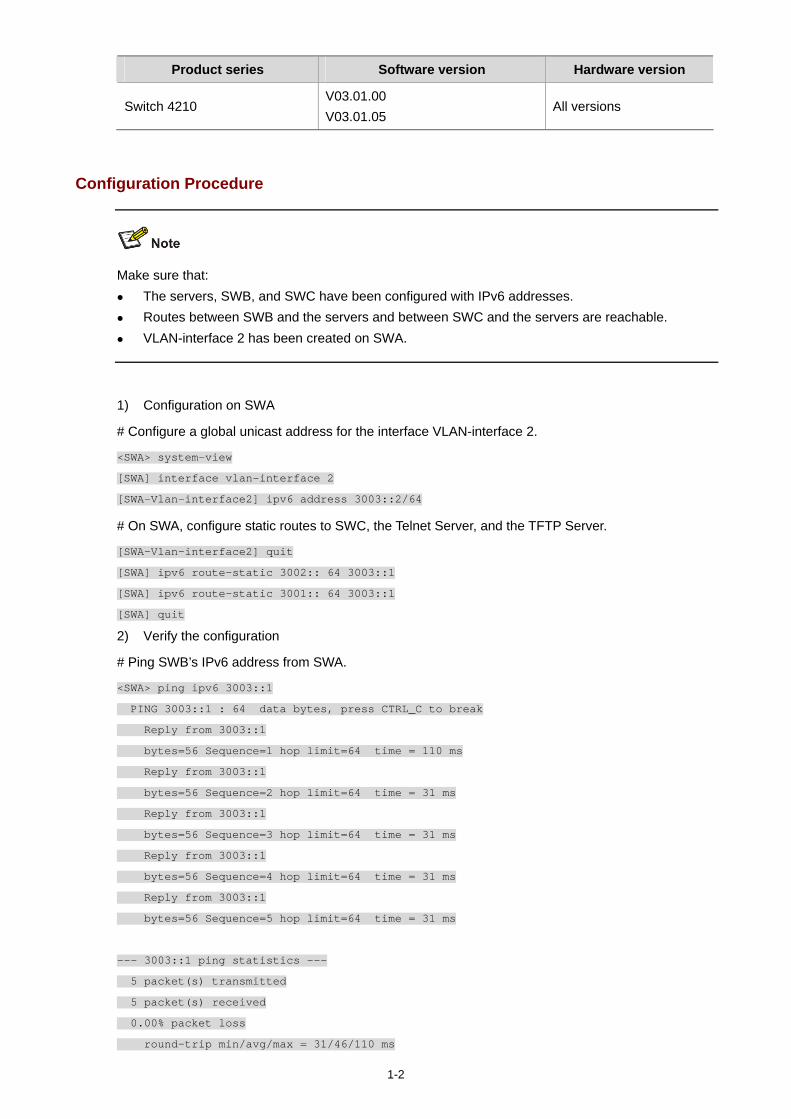
1-2
Product series Software version Hardware version
Switch 4210 V03.01.00 V03.01.05
All versions
Configuration Procedure
Make sure that: The servers, SWB, and SWC have been configured with IPv6 addresses. Routes between SWB and the servers and between SWC and the servers are reachable. VLAN-interface 2 has been created on SWA.
1) Configuration on SWA
# Configure a global unicast address for the interface VLAN-interface 2.
<SWA> system-view
[SWA] interface vlan-interface 2
[SWA-Vlan-interface2] ipv6 address 3003::2/64
# On SWA, configure static routes to SWC, the Telnet Server, and the TFTP Server.
[SWA-Vlan-interface2] quit
[SWA] ipv6 route-static 3002:: 64 3003::1
[SWA] ipv6 route-static 3001:: 64 3003::1
[SWA] quit
2) Verify the configuration
# Ping SWB’s IPv6 address from SWA.
<SWA> ping ipv6 3003::1
PING 3003::1 : 64 data bytes, press CTRL_C to break
Reply from 3003::1
bytes=56 Sequence=1 hop limit=64 time = 110 ms
Reply from 3003::1
bytes=56 Sequence=2 hop limit=64 time = 31 ms
Reply from 3003::1
bytes=56 Sequence=3 hop limit=64 time = 31 ms
Reply from 3003::1
bytes=56 Sequence=4 hop limit=64 time = 31 ms
Reply from 3003::1
bytes=56 Sequence=5 hop limit=64 time = 31 ms
--- 3003::1 ping statistics ---
5 packet(s) transmitted
5 packet(s) received
0.00% packet loss
round-trip min/avg/max = 31/46/110 ms
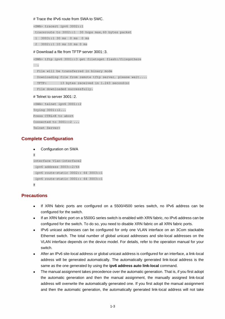
1-3
# Trace the IPv6 route from SWA to SWC.
<SWA> tracert ipv6 3002::1
traceroute to 3002::1 30 hops max,60 bytes packet
1 3003::1 30 ms 0 ms 0 ms
2 3002::1 10 ms 10 ms 0 ms
# Download a file from TFTP server 3001::3.
<SWA> tftp ipv6 3001::3 get filetoget flash:/filegothere
.
File will be transferred in binary mode
Downloading file from remote tftp server, please wait....
TFTP: 13 bytes received in 1.243 second(s)
File downloaded successfully.
# Telnet to server 3001::2.
<SWA> telnet ipv6 3001::2
Trying 3001::2...
Press CTRL+K to abort
Connected to 3001::2 ...
Telnet Server>
Complete Configuration
Configuration on SWA #
interface Vlan-interface2
ipv6 address 3003::2/64
ipv6 route-static 3002:: 64 3003::1
ipv6 route-static 3001:: 64 3003::1
#
Precautions
If XRN fabric ports are configured on a 5500/4500 series switch, no IPv6 address can be configured for the switch.
If an XRN fabric port on a 5500G series switch is enabled with XRN fabric, no IPv6 address can be configured for the switch. To do so, you need to disable XRN fabric on all XRN fabric ports.
IPv6 unicast addresses can be configured for only one VLAN interface on an 3Com stackable Ethernet switch. The total number of global unicast addresses and site-local addresses on the VLAN interface depends on the device model. For details, refer to the operation manual for your switch.
After an IPv6 site-local address or global unicast address is configured for an interface, a link-local address will be generated automatically. The automatically generated link-local address is the same as the one generated by using the ipv6 address auto link-local command.
The manual assignment takes precedence over the automatic generation. That is, if you first adopt the automatic generation and then the manual assignment, the manually assigned link-local address will overwrite the automatically generated one. If you first adopt the manual assignment and then the automatic generation, the automatically generated link-local address will not take

1-4
effect and the link-local address of an interface is still the manually assigned one. If the manually assigned link-local address is deleted, the automatically generated link-local address takes effect.
i
Table of Contents
1 Smart Link-Monitor Link Configuration Guide ·······················································································1-1 Smart Link Configuration Example ·········································································································1-1
Network diagram ·····························································································································1-1 Network requirements ·····················································································································1-1 Applicable Product Matrix················································································································1-1 Configuration procedure··················································································································1-2 Complete Configuration···················································································································1-3 Precautions······································································································································1-3
Implementing Collaboration Between Smart Link and Monitor Link ·······················································1-4 Network diagram ·····························································································································1-4 Network requirements ·····················································································································1-4 Applicable Product Matrix················································································································1-5 Configuration procedure··················································································································1-5 Complete Configuration···················································································································1-6 Precautions······································································································································1-7
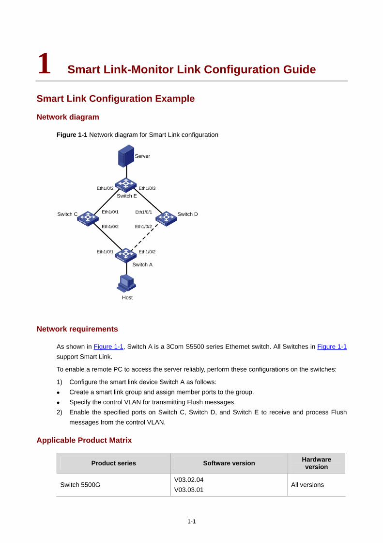
1-1
1 Smart Link-Monitor Link Configuration Guide
Smart Link Configuration Example
Network diagram
Figure 1-1 Network diagram for Smart Link configuration
Switch A
Eth1/0/1 Eth1/0/2
Switch C
Server
Eth1/0/1
Eth1/0/2 Eth1/0/2
Host
Switch D
Switch EEth1/0/3Eth1/0/2
Eth1/0/1
Network requirements
As shown in Figure 1-1, Switch A is a 3Com S5500 series Ethernet switch. All Switches in Figure 1-1 support Smart Link.
To enable a remote PC to access the server reliably, perform these configurations on the switches:
1) Configure the smart link device Switch A as follows: Create a smart link group and assign member ports to the group. Specify the control VLAN for transmitting Flush messages.
2) Enable the specified ports on Switch C, Switch D, and Switch E to receive and process Flush messages from the control VLAN.
Applicable Product Matrix
Product series Software version Hardware version
Switch 5500G V03.02.04 V03.03.01
All versions
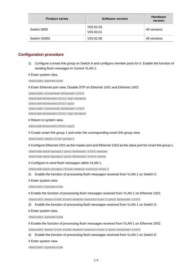
1-2
Product series Software version Hardware version
Switch 5500 V03.02.03 V03.03.01
All versions
Switch 4200G V03.02.00 All versions
Configuration procedure
1) Configure a smart link group on Switch A and configure member ports for it. Enable the function of sending flush messages in Control VLAN 1.
# Enter system view.
<switchA> system-view
# Enter Ethernet port view. Disable STP on Ethernet 1/0/1 and Ethernet 1/0/2.
[SwitchA] interface Ethernet 1/0/1
[SwitchA-Ethernet1/0/1] stp disable
[SwitchA-Ethernet1/0/1] quit
[SwitchA] interface Ethernet 1/0/2
[SwitchA-Ethernet1/0/2] stp disable
# Return to system view.
[SwitchA-Ethernet1/0/2] quit
# Create smart link group 1 and enter the corresponding smart link group view.
[SwitchA] smart-link group 1
# Configure Ethernet 1/0/1 as the master port and Ethernet 1/0/2 as the slave port for smart link group 1.
[SwitchA-smlk-group1] port Ethernet 1/0/1 master
[SwitchA-smlk-group1] port Ethernet 1/0/2 slave
# Configure to send flush messages within VLAN 1.
[SwitchA-smlk-group1] flush enable control-vlan 1
2) Enable the function of processing flush messages received from VLAN 1 on Switch C.
# Enter system view.
<SwitchC> system-view
# Enable the function of processing flush messages received from VLAN 1 on Ethernet 1/0/2.
<SwitchC> smart-link flush enable control-vlan 1 port Ethernet 1/0/2
3) Enable the function of processing flush messages received from VLAN 1 on Switch D.
# Enter system view.
<SwitchD> system-view
# Enable the function of processing flush messages received from VLAN 1 on Ethernet 1/0/2.
[SwitchD] smart-link flush enable control-vlan 1 port Ethernet 1/0/2
4) Enable the function of processing flush messages received from VLAN 1 on Switch E.
# Enter system view.
<SwitchE> system-view
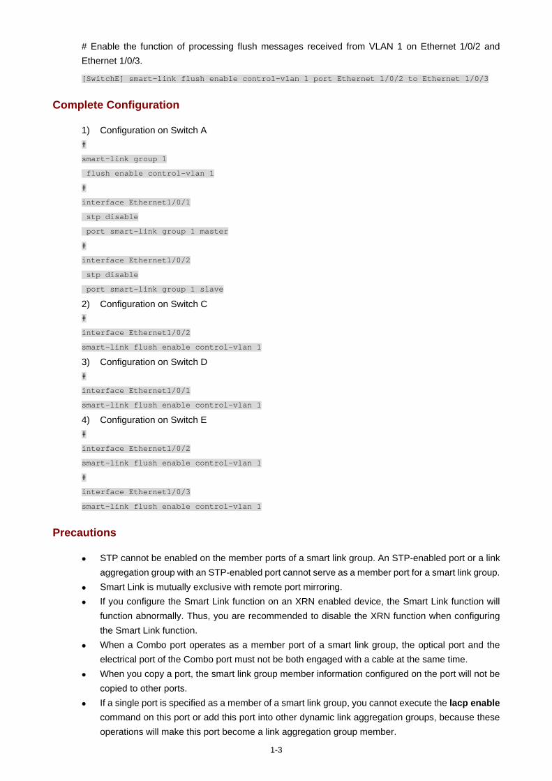
1-3
# Enable the function of processing flush messages received from VLAN 1 on Ethernet 1/0/2 and Ethernet 1/0/3.
[SwitchE] smart-link flush enable control-vlan 1 port Ethernet 1/0/2 to Ethernet 1/0/3
Complete Configuration
1) Configuration on Switch A #
smart-link group 1
flush enable control-vlan 1
#
interface Ethernet1/0/1
stp disable
port smart-link group 1 master
#
interface Ethernet1/0/2
stp disable
port smart-link group 1 slave
2) Configuration on Switch C #
interface Ethernet1/0/2
smart-link flush enable control-vlan 1
3) Configuration on Switch D #
interface Ethernet1/0/1
smart-link flush enable control-vlan 1
4) Configuration on Switch E #
interface Ethernet1/0/2
smart-link flush enable control-vlan 1
#
interface Ethernet1/0/3
smart-link flush enable control-vlan 1
Precautions
STP cannot be enabled on the member ports of a smart link group. An STP-enabled port or a link aggregation group with an STP-enabled port cannot serve as a member port for a smart link group.
Smart Link is mutually exclusive with remote port mirroring. If you configure the Smart Link function on an XRN enabled device, the Smart Link function will
function abnormally. Thus, you are recommended to disable the XRN function when configuring the Smart Link function.
When a Combo port operates as a member port of a smart link group, the optical port and the electrical port of the Combo port must not be both engaged with a cable at the same time.
When you copy a port, the smart link group member information configured on the port will not be copied to other ports.
If a single port is specified as a member of a smart link group, you cannot execute the lacp enable command on this port or add this port into other dynamic link aggregation groups, because these operations will make this port become a link aggregation group member.
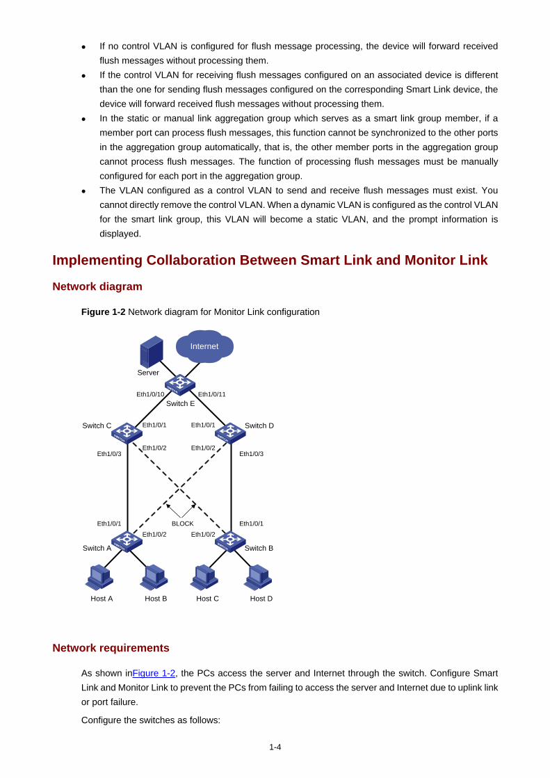
1-4
If no control VLAN is configured for flush message processing, the device will forward received flush messages without processing them.
If the control VLAN for receiving flush messages configured on an associated device is different than the one for sending flush messages configured on the corresponding Smart Link device, the device will forward received flush messages without processing them.
In the static or manual link aggregation group which serves as a smart link group member, if a member port can process flush messages, this function cannot be synchronized to the other ports in the aggregation group automatically, that is, the other member ports in the aggregation group cannot process flush messages. The function of processing flush messages must be manually configured for each port in the aggregation group.
The VLAN configured as a control VLAN to send and receive flush messages must exist. You cannot directly remove the control VLAN. When a dynamic VLAN is configured as the control VLAN for the smart link group, this VLAN will become a static VLAN, and the prompt information is displayed.
Implementing Collaboration Between Smart Link and Monitor Link
Network diagram
Figure 1-2 Network diagram for Monitor Link configuration
BLOCK
Switch A Switch B
Eth1/0/1Eth1/0/2
Switch C Switch D
Switch E
Eth1/0/1
Eth1/0/2Eth1/0/3
Server
Eth1/0/2
Eth1/0/2
Eth1/0/1
Eth1/0/1
Eth1/0/3
Eth1/0/11Eth1/0/10
Host A Host DHost CHost B
Internet
Network requirements
As shown inFigure 1-2, the PCs access the server and Internet through the switch. Configure Smart Link and Monitor Link to prevent the PCs from failing to access the server and Internet due to uplink link or port failure.
Configure the switches as follows:
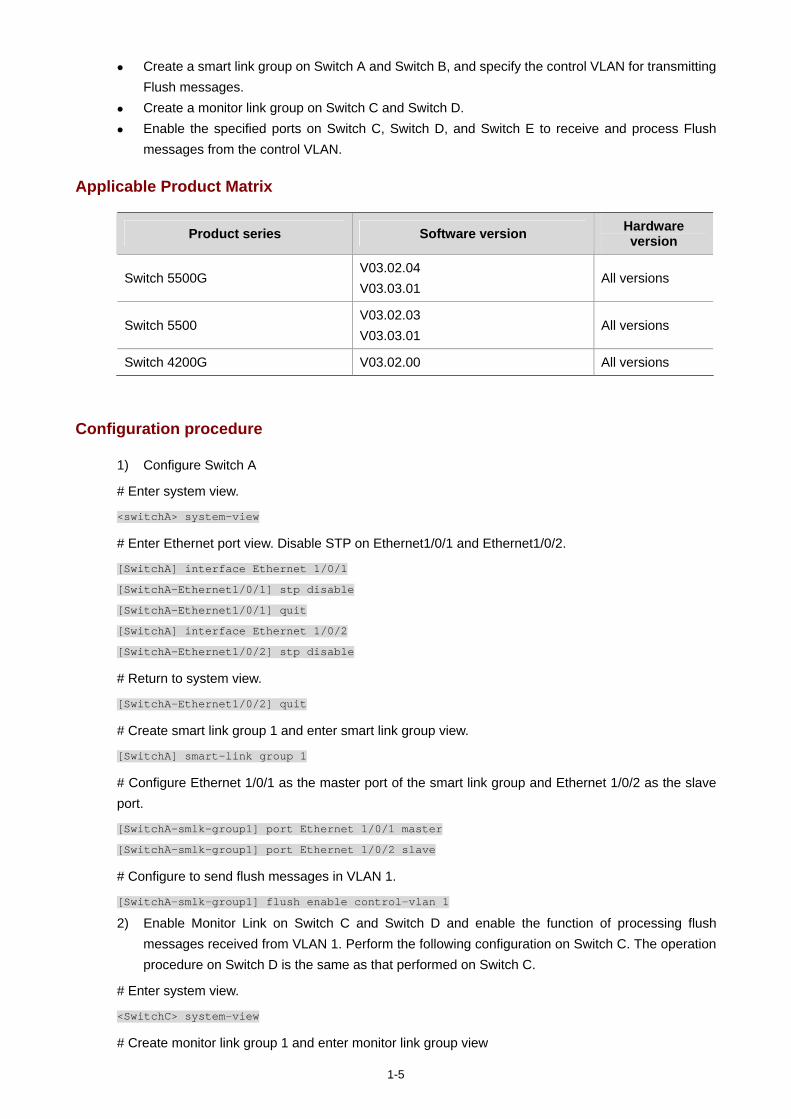
1-5
Create a smart link group on Switch A and Switch B, and specify the control VLAN for transmitting Flush messages.
Create a monitor link group on Switch C and Switch D. Enable the specified ports on Switch C, Switch D, and Switch E to receive and process Flush
messages from the control VLAN.
Applicable Product Matrix
Product series Software version Hardware version
Switch 5500G V03.02.04 V03.03.01
All versions
Switch 5500 V03.02.03 V03.03.01
All versions
Switch 4200G V03.02.00 All versions
Configuration procedure
1) Configure Switch A
# Enter system view.
<switchA> system-view
# Enter Ethernet port view. Disable STP on Ethernet1/0/1 and Ethernet1/0/2.
[SwitchA] interface Ethernet 1/0/1
[SwitchA-Ethernet1/0/1] stp disable
[SwitchA-Ethernet1/0/1] quit
[SwitchA] interface Ethernet 1/0/2
[SwitchA-Ethernet1/0/2] stp disable
# Return to system view.
[SwitchA-Ethernet1/0/2] quit
# Create smart link group 1 and enter smart link group view.
[SwitchA] smart-link group 1
# Configure Ethernet 1/0/1 as the master port of the smart link group and Ethernet 1/0/2 as the slave port.
[SwitchA-smlk-group1] port Ethernet 1/0/1 master
[SwitchA-smlk-group1] port Ethernet 1/0/2 slave
# Configure to send flush messages in VLAN 1.
[SwitchA-smlk-group1] flush enable control-vlan 1
2) Enable Monitor Link on Switch C and Switch D and enable the function of processing flush messages received from VLAN 1. Perform the following configuration on Switch C. The operation procedure on Switch D is the same as that performed on Switch C.
# Enter system view.
<SwitchC> system-view
# Create monitor link group 1 and enter monitor link group view
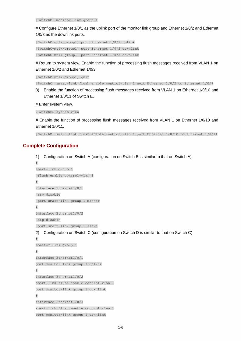
1-6
[SwitchC] monitor-link group 1
# Configure Ethernet 1/0/1 as the uplink port of the monitor link group and Ethernet 1/0/2 and Ethernet 1/0/3 as the downlink ports.
[SwitchC-mtlk-group1] port Ethernet 1/0/1 uplink
[SwitchC-mtlk-group1] port Ethernet 1/0/2 downlink
[SwitchC-mtlk-group1] port Ethernet 1/0/3 downlink
# Return to system view. Enable the function of processing flush messages received from VLAN 1 on Ethernet 1/0/2 and Ethernet 1/0/3.
[SwitchC-mtlk-group1] quit
[SwitchC] smart-link flush enable control-vlan 1 port Ethernet 1/0/2 to Ethernet 1/0/3
3) Enable the function of processing flush messages received from VLAN 1 on Ethernet 1/0/10 and Ethernet 1/0/11 of Switch E.
# Enter system view.
<SwitchE> system-view
# Enable the function of processing flush messages received from VLAN 1 on Ethernet 1/0/10 and Ethernet 1/0/11.
[SwitchE] smart-link flush enable control-vlan 1 port Ethernet 1/0/10 to Ethernet 1/0/11
Complete Configuration
1) Configuration on Switch A (configuration on Switch B is similar to that on Switch A) #
smart-link group 1
flush enable control-vlan 1
#
interface Ethernet1/0/1
stp disable
port smart-link group 1 master
#
interface Ethernet1/0/2
stp disable
port smart-link group 1 slave
2) Configuration on Switch C (configuration on Switch D is similar to that on Switch C) #
monitor-link group 1
#
interface Ethernet1/0/1
port monitor-link group 1 uplink
#
interface Ethernet1/0/2
smart-link flush enable control-vlan 1
port monitor-link group 1 downlink
#
interface Ethernet1/0/3
smart-link flush enable control-vlan 1
port monitor-link group 1 downlink
1-7
3) Configuration on Switch E #
interface Ethernet1/0/10
smart-link flush enable control-vlan 1
#
interface Ethernet1/0/11
smart-link flush enable control-vlan 1
Precautions
You cannot assign a port or link aggregation group to more than one smart link group or to a smart link group and monitor link group at the same time.
Smart Link is mutually exclusive with remote port mirroring. If you configure both the Smart Link and Monitor Link functions on an XRN enabled device, the
Smart Link and Monitor Link functions will function abnormally. Thus, you are recommended to disable the XRN function when configuring the Smart Link or Monitor Link function.
If a single port is specified as a smart link/monitor link group member, do not use the lacp enable command on the port or add the port to another dynamic link aggregation group because doing so will cause the port to become an aggregation group member.
Using the copy command on a port does not copy the smart link/monitor link group member information configured on the port to any other port.

i
Table of Contents
1 VLAN Mapping Configuration Guide ·······································································································1-1 Configuring VLAN Mapping ····················································································································1-1
Network Diagram·····························································································································1-1 Networking and Configuration Requirements··················································································1-1 Applicable Product Matrix················································································································1-2 Configuration procedure··················································································································1-2 Complete Configuration···················································································································1-3 Precautions······································································································································1-4
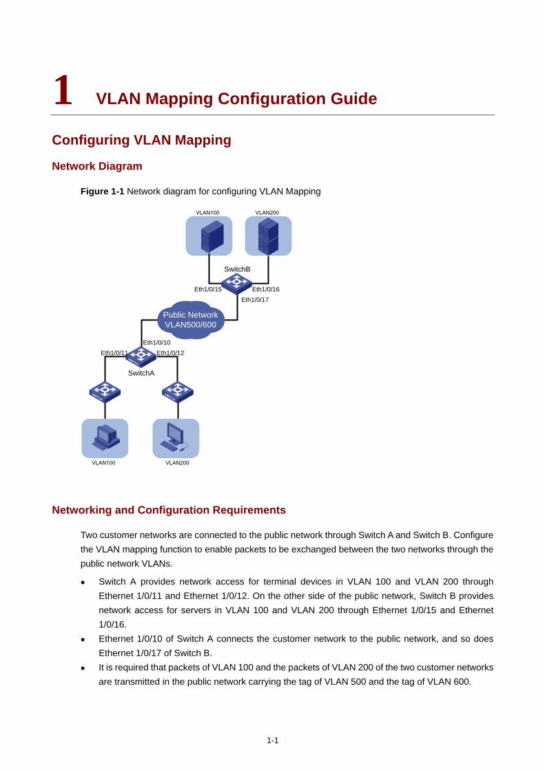
1-1
1 VLAN Mapping Configuration Guide
Configuring VLAN Mapping
Network Diagram
Figure 1-1 Network diagram for configuring VLAN Mapping
Eth1/0/11 Eth1/0/12Eth1/0/10
VLAN100 VLAN200
VLAN100 VLAN200
SwitchA
SwitchB
Eth1/0/15 Eth1/0/16Eth1/0/17
Public NetworkVLAN500/600
Networking and Configuration Requirements
Two customer networks are connected to the public network through Switch A and Switch B. Configure the VLAN mapping function to enable packets to be exchanged between the two networks through the public network VLANs.
Switch A provides network access for terminal devices in VLAN 100 and VLAN 200 through Ethernet 1/0/11 and Ethernet 1/0/12. On the other side of the public network, Switch B provides network access for servers in VLAN 100 and VLAN 200 through Ethernet 1/0/15 and Ethernet 1/0/16.
Ethernet 1/0/10 of Switch A connects the customer network to the public network, and so does Ethernet 1/0/17 of Switch B.
It is required that packets of VLAN 100 and the packets of VLAN 200 of the two customer networks are transmitted in the public network carrying the tag of VLAN 500 and the tag of VLAN 600.
1-2
Applicable Product Matrix
Use ACLs to match packets carrying the specified VLAN ID and then map the VLAN ID to the specified VLAN ID. You can configure VLAN mapping on a switch connecting the customer network to the service provider network. VLAN mapping can satisfy the service provider network’s planning requirements by mapping the specified customer VLAN ID to the specified service VLAN ID.
Product series Software version Hardware version
Switch 5500G V03.02.04 V03.03.01
All versions
Switch 5500 V03.02.03 V03.03.01
All versions
Switch 4500 V03.02.00 V03.03.00
All versions
Switch 4200G V03.02.00 All versions
Configuration procedure
# Create customer VLANs VLAN 100 and VLAN 200 and service VLANs VLAN 500 and VLAN 600 on Switch A.
<SwitchA> system-view
[SwitchA] vlan 100
[SwitchA-vlan100] quit
[SwitchA] vlan 200
[SwitchA-vlan200] quit
[SwitchA] vlan 500
[SwitchA-vlan500] quit
[SwitchA] vlan 600
[SwitchA-vlan600] quit
# Configure Ethernet 1/0/11 of Switch A as a trunk port and configure its default VLAN as VLAN 100. Assign Ethernet 1/0/11 to VLAN 100 and VLAN 500. Configure Ethernet 1/0/12 in the same way.
[SwitchA] interface Ethernet 1/0/11
[SwitchA-Ethernet1/0/11] port link-type trunk
[SwitchA-Ethernet1/0/11] port trunk pvid vlan 100
[SwitchA-Ethernet1/0/11] port trunk permit vlan 100 500
[SwitchA-Ethernet1/0/11] quit
[SwitchA] interface Ethernet 1/0/12
[SwitchA-Ethernet1/0/12] port link-type trunk
[SwitchA-Ethernet1/0/12] port trunk pvid vlan 200
[SwitchA-Ethernet1/0/12] port trunk permit vlan 200 600
[SwitchA-Ethernet1/0/12] quit
# Configure Ethernet 1/0/10 of Switch A as a trunk port, and assign it to VLAN 100, VLAN 200, VLAN 500, and VLAN 600.
[SwitchA] interface Ethernet 1/0/10
[SwitchA-Ethernet1/0/10] port link-type trunk
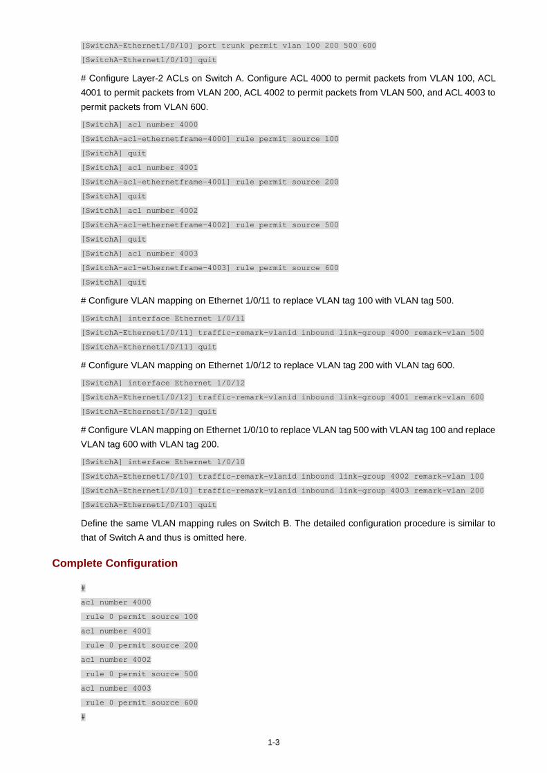
1-3
[SwitchA-Ethernet1/0/10] port trunk permit vlan 100 200 500 600
[SwitchA-Ethernet1/0/10] quit
# Configure Layer-2 ACLs on Switch A. Configure ACL 4000 to permit packets from VLAN 100, ACL 4001 to permit packets from VLAN 200, ACL 4002 to permit packets from VLAN 500, and ACL 4003 to permit packets from VLAN 600.
[SwitchA] acl number 4000
[SwitchA-acl-ethernetframe-4000] rule permit source 100
[SwitchA] quit
[SwitchA] acl number 4001
[SwitchA-acl-ethernetframe-4001] rule permit source 200
[SwitchA] quit
[SwitchA] acl number 4002
[SwitchA-acl-ethernetframe-4002] rule permit source 500
[SwitchA] quit
[SwitchA] acl number 4003
[SwitchA-acl-ethernetframe-4003] rule permit source 600
[SwitchA] quit
# Configure VLAN mapping on Ethernet 1/0/11 to replace VLAN tag 100 with VLAN tag 500.
[SwitchA] interface Ethernet 1/0/11
[SwitchA-Ethernet1/0/11] traffic-remark-vlanid inbound link-group 4000 remark-vlan 500
[SwitchA-Ethernet1/0/11] quit
# Configure VLAN mapping on Ethernet 1/0/12 to replace VLAN tag 200 with VLAN tag 600.
[SwitchA] interface Ethernet 1/0/12
[SwitchA-Ethernet1/0/12] traffic-remark-vlanid inbound link-group 4001 remark-vlan 600
[SwitchA-Ethernet1/0/12] quit
# Configure VLAN mapping on Ethernet 1/0/10 to replace VLAN tag 500 with VLAN tag 100 and replace VLAN tag 600 with VLAN tag 200.
[SwitchA] interface Ethernet 1/0/10
[SwitchA-Ethernet1/0/10] traffic-remark-vlanid inbound link-group 4002 remark-vlan 100
[SwitchA-Ethernet1/0/10] traffic-remark-vlanid inbound link-group 4003 remark-vlan 200
[SwitchA-Ethernet1/0/10] quit
Define the same VLAN mapping rules on Switch B. The detailed configuration procedure is similar to that of Switch A and thus is omitted here.
Complete Configuration
#
acl number 4000
rule 0 permit source 100
acl number 4001
rule 0 permit source 200
acl number 4002
rule 0 permit source 500
acl number 4003
rule 0 permit source 600
#
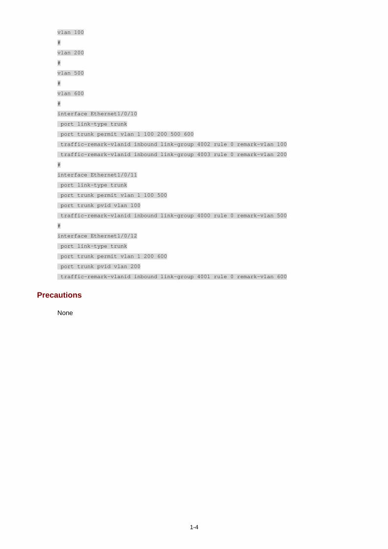
1-4
vlan 100
#
vlan 200
#
vlan 500
#
vlan 600
#
interface Ethernet1/0/10
port link-type trunk
port trunk permit vlan 1 100 200 500 600
traffic-remark-vlanid inbound link-group 4002 rule 0 remark-vlan 100
traffic-remark-vlanid inbound link-group 4003 rule 0 remark-vlan 200
#
interface Ethernet1/0/11
port link-type trunk
port trunk permit vlan 1 100 500
port trunk pvid vlan 100
traffic-remark-vlanid inbound link-group 4000 rule 0 remark-vlan 500
#
interface Ethernet1/0/12
port link-type trunk
port trunk permit vlan 1 200 600
port trunk pvid vlan 200
traffic-remark-vlanid inbound link-group 4001 rule 0 remark-vlan 600
Precautions
None