39673 Rev 2 - Westerbekes manual/39673_rev2_8.… · · 2016-05-24ENGINE TYPE Diesel, 4 cycle, 3...
75
OPERATIONS & MAINTENANCE MANUAL WESTERBEKE DIESEL GENERATORS MOBILE & INDUSTRIAL MODEL 8.0 BTDR, 10.0 BTDR, 11.0 BTDR AND 12.5 BTDAR SINGLE & THREE PHASE GENERATORS Publication #039673 Edition Two October 1993 'WESTERBEKE WESTERBEKE CORPORATION· MYLES STANDISH INDUSTRIAL PARK • 150 JOHN HANCOCK ROAD, TAUNTON, MA 02780-7319 U.S.A.
Transcript of 39673 Rev 2 - Westerbekes manual/39673_rev2_8.… · · 2016-05-24ENGINE TYPE Diesel, 4 cycle, 3...

OPERATIONS & MAINTENANCE
MANUAL
WESTERBEKE
DIESEL GENERATORS MOBILE & INDUSTRIAL
MODEL 8.0 BTDR, 10.0 BTDR, 11.0 BTDR AND 12.5 BTDAR
SINGLE & THREE PHASE GENERATORS
Publication #039673
Edition Two October 1993
jr~ 'WESTERBEKE ~ WESTERBEKE CORPORATION· MYLES STANDISH INDUSTRIAL PARK
• 150 JOHN HANCOCK ROAD, TAUNTON, MA 02780-7319 U.S.A.

IMPORTANT
PRODUCT SOFTWARE DISCLAIMER
Product software of all kinds, such as brochures, drawings, technical data, operator's and workshop manuals, parts ~sts and parts price lists, and other information, instructions and specifications provided from sources other than Westerbeke, is not within Westerbeke's control and, accordingly, is provided to Westerbeke customers only as a courtesy and service. WESTERBEKECANNOT BE RESPONSmLE FOR THE CONTENT OF SUCH SOFTWARE, MAKES. NO WARRANTIES' OR REPRESENTATIONS w:o:E: RESPECT THERETO, rnCI:.UDrnG ACCURACY, TlMELINESS ORCOMPLETENESS THEREOF, ANb WILL IN NO EVENT BE LIABLE FOR ANY TYPE OF DAMAGES OR INJURY INCURRED rn CONNECTION WITH, OR, ARISrnG OUT OF, THE FURNISHING OR USE OF SUCH SOFTWARE.
For example, components and subassemblies incorporated in Westerbeke's products and supplied by others (such as engine blocks, fuel systems and components, 'transmissions, electrical components, pumps and other products) are generally supported by their manufacturers with their own software, and Westerbeke must depend on such software for the design ofWesterbeke's own product software. Such software may be outdated and no longer accurate. Routine changes made by Westerbeke's suppliers, of which Westerbeke rarely has notice in advance, are frequently not reflected in the supplier's software until after such changes take place.
Westerbeke customers should also keep in mind the time span between printings of Westerbeke product software, and the unavoidable. existence of earlier, non-current Westerbeke software editions in the field. Additionally, most Westerbeke products include customer-requested special features that frequently do not include complete documentation.
In summation, product software provided with Westerbeke products, whether from , Westerbeke or other suppliers, must not and cannot be relied upon exclusively as the definitive authority on the respective product. It not' only makes good sense but is imperative that appropriate representatives ofWesterbeke or the supplier in question be consulted to determine the accuracy and currentness of the product software being consulted by the customer.
CALIFORNIA Proposition 65 Warning
Diesel engine exhaust and some of its constituents are ~oown to the State of California to cause cancer. birth defects, and other reproductive harm. '

INTRODUCTION
Thank you for purchasing a Westerbeke diesel generator. With proper care on a routine basis, your Westerbeke generator is designed to provide you with reliable and economical power for many years.
This manual will help familiarize you with your engine. It covers initial service, operation, maintenance and troubleshooting in depth.
It also contains important safety information, key specifications, and a wiring diagram.
No manual can provide for every possible question or contingency. If you should need further assistance, please contact the Westerbeke Master Distributor located nearest you for technical advice.
Again, thank you for choosing a Westerbeke!
Sincerely,
WESTERBEKE CORPORATION
1 Westerbeke Generators

ENGINE SERIAL NUMBER LOCATION
The engine serial number and model designation are found on an I.D. tag affixed to the generator's housing. An illustration of this I.D. tag is shown below. Take the time to fill in the model description, engine serial number and generator serial number in the appropriate blocks in the illustration below. These will provide quick reference when ordering spares, repair parts or when seeking technical infonnation .
.. -.. - -.-.- . ................. -'
MODEL __
ENG. SER. NO._
GEN. SER. NO._
KW ___ _
KVA __ _
PF I PHASE_ HZ ___ _
WIRES __ _
RATING __
VOLTS _---"-_ AMPS __ _
INSUL. CLASS_
TEMP. RISE_
BATTERY __
ENG. HP __
CJ.D. __ _
RPM __ -::--
Engine Serial Number Stamp
The engine serial number can also be found stamped into the engine block on the flat outer surface where the injection pump is mounted. The generator serial number is stamped into the generator housing on the flat surface above the rear generator bearing.
Westerbeke Generators 2

BE SAFETY CONSCIOUS
A careless moment can cause an accident or fire. Here are basic DO's and DONTS:
DO'S
• DO visual inspections before starting your generator.
• DO check your engine once a day. Keep eyes open and be alert to people and obstacles.
3
DON'TS
•
•
DONT touch any moving part on your engine during operation.
DONT touch hot engine parts such as exhaust manifolds.
Westerbeke Generators

•
•
DO keep fuel away from your engine • at all times. Check for leaks regularly and correct them.
DO check the capacity of sling hoist when lifting the unit. Use hangers and a wad of cloth in between sling and unit.
•
Westerbeke Generators 4
DON'T remove radiator filler cap immediately after shutting down engIne.
DON'T smoke near the battery Never use an open flame as a light anywhere on or around the battery. Battery gas is highly flammable. Sulfuric acid is destructive. If it comes in contact with your skin, wash it off at once with water.

5
• DON'T work on an engine while it is running. If it is necessary to check the engine while running, use caution and beware of moving parts and the presence of AC voltage.
• DON'T touch AC electrical connections while the unit is running. Lethal voltage is present at these connections.
Westerbeke Generators

NOTES, CAUTIONS AND WARNINGS
NOTES, CAUTIONS, AND WARNINGS are used in this manual to emphasize important and critical instructions. They are used for the following conditions:
NOTE
An operating procedure, condition, etc. essential to notate.
CAUflON
Operating procedures, practices, etc. which if not strictly observed, will result in damage or destruction to your engine.
WARNING
Operating procedures, practices, etc. which if not correctly followed, will result in personal injury or loss of life.
DEFINITION OF LOCAL TERMS
The words "Ieftside", "rightside", "front", and "rear" are used in the senses illustrated below:
Front (Radiator End)
Westerbeke Generators
Right
0000 Left
6
Rear (Generator End)

TABLE OF CONTENTS
GETTING TO KNOW YOUR GENERATOR
SPECIFICATIONS (General and System)
8.0BTDR 10.0 BTDR 11.0 BTDR 12.5BTDR
CONTROLS AND INSTRUMENTS
NEW GENERATOR INITIAL INSPECTION
DAILY WALK AROUND CHECKS
DIESEL FUEL, ENGINE OIL, COOLING WATER
OPERATING YOUR GENERATOR
STARTING WARMlNGUP STOPPING
ROUTINE-SERVICE
SERVICE ITEMS
SAFETY-RULES SERVICE SCHEDULE
ENGINE OIL & FILTER CYLINDERHEADBOLTSAND VALVE ADJUSTMENTS
8.0 & 10.0 BTDR 11.0 & 12.5 BTDR
INJECTOR SERVICING AIR CLEANER ELEMENT
7
PAGE
9
13 18 24 29
35
37
38
39
41
41 42 42
43
43 44
47
47
48 49,50 51 51
Westerbeke Generators

FAN BELT ENGINE COOLANT GENERA TOR ADJUSTMENTS GENERA TOR MAINTENANCE
ENGINE DC WIRING
BT GENERATOR 8.0 BTDR SINGLE PHASE 10.0, 11.0, 12.5 BTDR SINGLE PHASE 10.0, 11.0, 12.5 BTDR THREE PHASE
NO LOAD VOLTAGE ADJUSTMENT
8.0 BTDR SINGLE PHASE 10.0, 11.0, 12.5 BTDR SINGLE PHASE 10.0,11.0,12.5 BTDR THREE PHASE
AC VOLTAGE REGULATOR
TORQUESPECllITCATIONS
Westerbeke Generators 8
52 52 53 53
57 58 62 66
60 64 67
67
71
\0
~ ~ (1) a~ (1)
~ ~ ~ Q en
Radiator Fill Cap \,.
Radiator _________
Drain Petcock
Top Engine Oil Fill
8.0 &10.0 BTDR GENERATOR LEFT SIDE
Emergency Shut-off Switch
Unit Data Tag
Starter with Solenoid

~ ~ CD do ~
I o ~
-o
Control Panel
20 Amp DC Circuit Breaker
Fresh Water Block Drain
AC Connections Outlet
Air Cleaner Housing
Fuel Lift Pump
Water Temperature Switch
Fuel Filter
Lube Oil Filter Lube Oil Dipstick
8.0 & 10.0 BTDR GENERATOR RIGHT SIDE
Injection Pump
Fuel Run Solenoid
Lube Oil Drain Hose
Oil Pressure Switch
il Pressure Sender

.......
.......
~ :4 CD a-~ CD
r a ~
, Radiator Fill Cap
\
Radiator'
DC Charging Alternator
Starter with Solenoid DC Battery Ground Connection
11.0 BTDR & 12~5 BTDAR LEFT SIDE
Unit Data Plate

~ (1)
~ (1) a~ (1)
~ ~ a. ~
-N
Air Cleaner Housing
Preheat Solenoid
20 Amp DC Circuit Breaker
AC Connections Outlet
Fresh'Water Block Drain
Water Temperature Switch and Sender
'lube Oil Filter
Fuel Injection Pump
Fuel Run Solenoid
'Oil Pressure Sender
Oil Pressure Switch'
Lube Oil Drain Hose
Coolant Recovery Tank
Secondary Fuel Filter
, Fuel Lift ,Pump'
11.0 BTD~ ;r~112.5 BTDAR i RIGHT SIDE

8.0 BTDR DIESEL GENERATOR
SINGLE PHASE
GENERAL SPECIFICATIONS
ENGINE TYPE Diesel, 4 cycle, 3 cylinder, fresh water cooled. Vertical, in-line overhead valve mechanism (14 hp at 1800 rpm maximum).
GOVERNOR Mechanical, centrifugal weight type.
COMBUSTION CHAMBER Swirl chamber type.
BORE & STROKE 2.87 x 3.07 inches (73 x 78 mm)
PISTON DISPLACEMENT 60 cubic inches (0.979 liters)
FIRING ORDER 1-3-2
DIRECTION OF ROTATION Clockwise, when viewed from the front
MAXllvillM TORQUE (AT 1800 RPM) 41.5 lb-ft (5.73 kg-m)
COMPRESSION RATIO 23: 1
COMPRESSION PRESSURE 455.2 psi (32 kg/cm) at 280 rpm
VALVE TTh1ING Intake Opens 18° BIDC Intake Closes 46° ABDC
VALVE SEAT ANGLE
VALVE CLEARANCE (Engine Cold)
ENGINE SPEED
13
Exhaust Opens 46° BBDC Exhaust Closes 18° AIDC
Intake 45° Exhaust 45°
Intake 0.0098 inches (0.25 mm) Exhaust 0.0098 inches (0.25 mm)
1800 rpm 60 Hertz 1500 rpm 50 Hertz
Westerbeke Generators

GEl\TERAL SPECIFICATIONS CONTINUED .....
DIMENSIONS
WEIGHT
FUEL CONSUMPTION
Westerbeke Generators
Height: 24.7 inches (627.3 mm) Width: 20.4 inches (518.1 mm) Length: 36.1 inches (916.9 mm)
465 lbs. (211· kgs)
0.9 gph (3.40 lph) at full rated output (approximate)
14

8.0 BTDR DIESEL GENERA TOR SINGLE PHASE
SYSTEM SPECIFICA nONS
FUEL SYSTEM:
GENERAL
FUEL
FUEL INJECTION PUMP
FUEL INJECTION TIMING
NOZZLE
INJECTORS
FUEL PUMP
FUEL FILTER ( on engine)
AIR CLEANER
AIR FLOW ( engine combustion)
COOLING SYSTEM:
GENERAL
OPERATING TEMPERATURE
FRESH WATER PUMP
SYSTEM CAPACITY (Fresh Water)
LUBRICATION SYSTEM:
GENERAL
15
Open flow, totally self-bleeding
No.2 Diesel oil (cetane rating of 45 or higher)
Nippon Denso (Bosch M type)
190 BTDC ±C.5 (static timing)
Throttle type
Pintle type
12-Volt DC
Canister type, with replaceable element
Replaceable element
32 cfm (.906 cmm)
Closed fresh water-cooled block, thermostatically controlled with radiator
1750 - 1950 F (800 - 91 0 C)
Centrifugal type, metal impeller, belt-driven.
10 quarts approximately
Pressure type by Trichoid pump, gear driven with external pressure relief valve
Westerbeke Generators
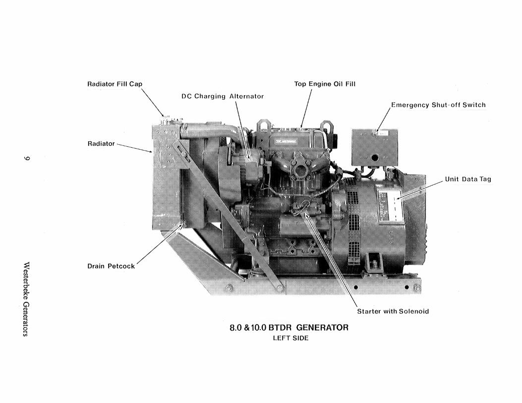
SYSTEM SPECIFICATIONS CONTINUED •••
OIL FILTER
SUMP CAPACITY (includes filter)
OPERATING OIL PRESSURE ( engine hot)
OIL GRADE
ELECTRICAL SYSTEM:
STARTING BATTERY
BATTERY CAPACITY
DC CHARGING ALTERNATOR
REGULATOR
STARTING AID
STARTER
DC NO-LOAD CURRENT
DC CRANKING CURRENT
AC GENERATOR GENERAL:
SINGLE PHASE ONLY
Westerbeke Generators
Full flow, paper element, spin-on type
3.3 quarts (3.12 liters)
40 - 50 psi (2.8 - 3.5 kg/cm)
API SPECIFICA nON CF OR CG-4 . SAE 30W, lOW-30 OR lSW-40
12 volt 30 A-H, (-) negative ground (recommended) (45 A-H in cold areas)
90 - 125 (Ampere - Hours)
12 volt DC, 50 amp
Internal regulator built into the DC alternator
Glow plug, sheathed type.
12 volt, 1.2 KW, reduction type solenoid mounted
90 amp (max.) at 11.5 volts
175-200 amps ( engine cold)
Brushless, four pole, revolving field. Pre-lubricated single-bearing design. Reconnectable, single phase transformer regulated.
16

SYSTEM SPECIFICA nONS CONTINUED ••.
VOLT AGE (Single Phase)
RATING (Volts AC)
60 Hertz (1800 RPM) 8.0KW
50 Hertz (1500 RPM) 6.0KW
GENERATOR COOLING:
AIR REQUIREMENTS 60 Hertz at 1800 rpm
120 OR 120/240 volts- 60 Hertz 220 volts - 50 Hertz Voltage regulation 5% no load to full load Frequency regulation: 3 Hertz (5%) no load to full load.
120 volts 66 amps 120/240 Volts 66/33 amps
220 volts 27 amps
175 -200 cfm (4.95 - 5.66 cmm)
NOTE: Increase air supply 15% for 50 hertz operation (1500 rpm)
TUNE-UP SPECIFICATIONS:
INJECTOR PRESSURE
ENGINE TllvfING
17
1707 psi (120 kg/cm + 10 kg/cm - 0 kg/em)
19 BIDC (spill timing)
Westerbeke Generators

10.0 BTDR DIESEL GENERATOR
SINGLE PHASE & THREE PHASE
GENERALSPECnnCATIONS
ENGINE TYPE Diesel, 4 cycle, 3 cylinder, fresh water cooled. Vertical, in-line overhead valve mechanism (16.5 hp at 1800 rpm maximum).
GOVERNOR Mechanical, centrifugal weight type.
COMBUSTION CHAMBER Swirl chamber type.
BORE & STROKE 3.07 x 3.07 inches (78 x 78 mm)
PISTON DISPLACEMENT 68 cubic inches (1.121 liters)
FIRING ORDER 1-3-2
DIRECTION OF ROTATION Clockwise, when viewed from the front
MAXIMUM TORQUE (AT 1800 RPM) 47.7Ib-ft (6.6 kg-m)
COMPRESSION RATIO 23:1
COMPRESSION PRESSURE 455.2 psi (32 kg/cm) at 280 rpm
VALVE TIMING Intake Opens 18° BIDC Intake Closes 46° ABDC Exhaust Opens 46° BBDC Exhaust Closes 18° AIDC
VALVE SEAT ANGLE Intake 45° Exhaust 45°
VALVE CLEARANCE (Engine Cold)
ENGINE SPEED
Westerbeke Generators
Intake 0.0098 inches (0.25 mm) Exhaust 0.0098 inches (0.25 mm)
1800 rpm 60 Hertz 1500 rpm 50 Hertz
18
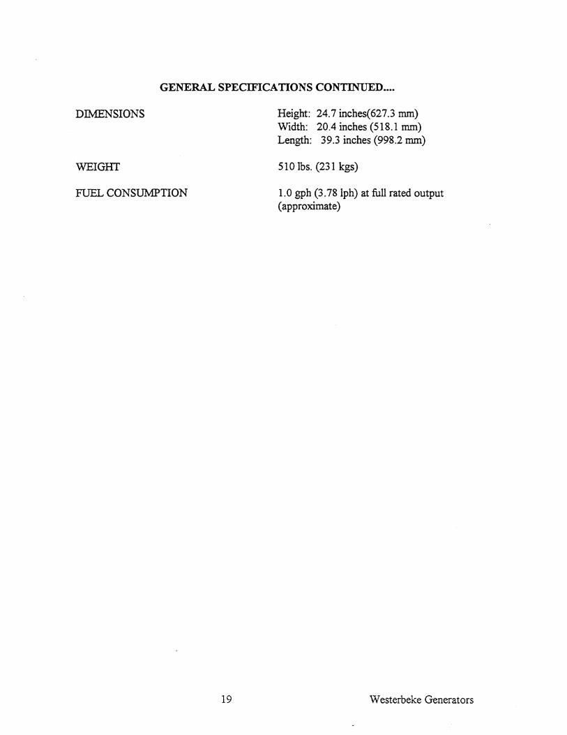
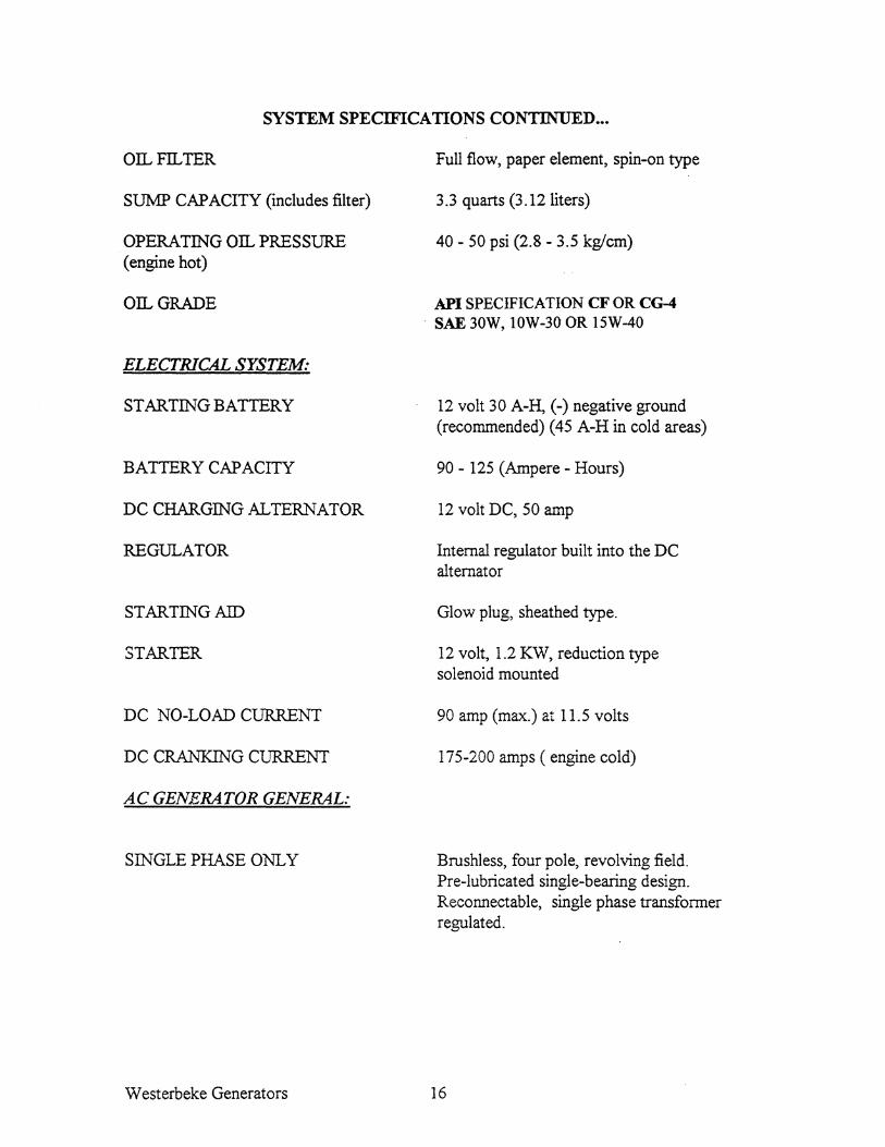
GENERAL SPECIFICA nONS CONTINUED ••••
DIMENSIONS
WEIGHT
FUEL CONSUMPTION
19
Height: 24.7 inches(627.3 mm) Width: 20.4 inches (518.1 mm) Length: 39.3 inches (998.2 mm)
5101bs. (231 kgs)
1.0 gph (3.78Iph) at full rated output ( approximate)
Westerbeke Generators

10.0 BTDR DIESEL GENERA TOR SINGLE PHASE & THREE
SYSTEM SPECIFICATIONS
FUEL SYSTEM:
GENERAL
FUEL
FUEL INJECTION PUMP
FUEL INJECTION TIMING
NOZZLE
INJECTORS
FUEL PUMP
FUEL FILTER ( on engine)
AIR CLEANER
AIR FLOW ( engine combustion)
COOLING SYSTEM:
GENERAL
OPERATING TEMPERATURE
FRESH WATER PUMP
SYSTEM CAPACITY (Fresh Water)
Westerbeke Generators
Open flow, totally self-bleeding
No.2 Diesel oil (cetane rating of 45 or higher)
Nippon Denso (Bosch M type)
190 BIDC ± 0.5 (static timing)
Throttle type
Pintle type
12-Volt DC
Canister type, with replaceable element
Replaceable element
36 cfin (1.02.cmm)
Closed fresh water-cooled block, thermostatically controlled with radiator
1750 - 1950 F (800 - 91 0 C)
Centrifugal type, metal impeller, belt -driven.
10 quarts approximately
20

SYSTEM SPECIFICA nONS CONTINUED ••.
LUBRICATION SYSTEM:
GENERAL
OIL FILTER
SUMP CAPACITY (includes filter)
OPERATING OIL PRESSURE ( engine hot)
OIL GRADE
ELECTRICAL SYSTEM:
STARTING BATTERY
BATTERY CAPACITY
DC CHARGING ALTERNATOR
REGULATOR
STARTING AID
STARTER
DC NO-LOAD CURRENT
DC CRANKING CURRENT
21
Pressure type by Trichoid pump, gear driven with external pressure relief valve
Full flow, paper element, spin-on type
3.3 quarts (3 .12 liters)
40 - 50 psi (2.8 - 3.5 kg/cm)
API SPECIFICATION CF OR CG4 SAE 30W, lOW-30 OR lSW-40
12 volt 30 A-H, (-) negative ground (recommended) (45 A-H in cold areas)
90 - 125 (Ampere - Hours)
12 volt DC, 50 amp
Internal regulator built into the DC alternator
Glow plug, sheathed type.
12 volt, 1.6KW, reduction type solenoid mounted
90 amp (max.) at 11.5 volts
225-250 amps (engine cold)
Westerbeke Generators

SYSTEM SPECIFICA nONS CONTINUED ...
AC GENERATOR GENERAL:
SINGLE PHASE
VOLTAGE (Single Phase)
RATING (Volts AC)
60 Hertz (1800 RPM) 10.0KW
50 Hertz (1500 RPM) 7.5KW
GENERAL THREE PHASE
RATING (Volts-Amps AC)
Westerbeke Generators
Brushless, four pole, revolving field. Pre-lubricated single-bearing design. Reconnectable, single phase transformer regulation (optional solid-state voltage regulation).
120 OR 120/240 volts- 60 Hertz 220 volts - 50 Hertz Voltage regulation 5% no load to full load Frequency regulation: 3 Hertz (5%) no load to full load.
120 volts 83.3 amps 120/240 83.3/4l.6 amps
220 volts 36.3amps
Brushless, four-pole, revolving field. Pre-lubricated single bearing design. Reconnectable, three phase. Solid state voltage regulated.
Voltage - Parallel WYE 208 volts Series WYE 480 volts Series Delta 240 volts
Voltage regulation: 2% no load to full rated amperage output. Frequency regulation: 3 Hertz (5%) no load to full load.
208 volts 480 volts 240 volts
22
34.7 amps 15.0 amps 30.1 amps

SYSTEM SPECIFICA nONS CONTINUED ••.
GENERATOR COOLING:
AIR REQUIREMENTS 60 Hertz at 1800 rpm
200-225 efin (5.66-6.37 emm)
NOTE: Increase air supply 15% for 50 hertz operation (1500 rpm)
TUNE-UP SPECIFICATIONS:
INJECTOR PRESSURE
ENGINE TIMING
23
1707 psi (120 kg/em + 10 kg/em - 0 kg/em)
19 BTDC (spill timing)
Westerbeke Generators

11.0 BTDR DIESEL GENERA TOR
SINGLE PHASE & THREE PHASE
GENERALSPECllITCATIONS
ENGINE TYPE Diesel, 4 cycle, 4 cylinder, fresh water cooled. Vertical, in-line overhead valve mechanism (16.5 hp at 1800 rpm maximum).
GOVERNOR Mechanical, centrifugal weight type.
COMBUSTION CHAMBER Swirl chamber type.
BORE & STROKE 2.87 x 3.07 inches (73 x 78 mm)
PISTON DISPLACEMENT 80 cubic inches (1.305 liters)
FIRING ORDER 1-3-4-2
DIRECTION OF ROTATION Clockwise, when viewed from the front
MAXIMUM TORQUE (AT 1800 RPM) 541b-ft (7.4 kg-m)
COMPRESSION RATIO 23: 1
COMPRESSION PRESSURE 455.2 psi (32 kg/em) at 280 rpm
VALVE TIMING Intake Opens 18° BIDC Intake Closes 46° ABDC Exhaust Opens 46° BBDC Exhaust Closes 18° ATDC
VALVE SEAT ANGLE
VALVE CLEARANCE (Engine Cold)
ENGINE SPEED
Westerbeke Generators
Intake 45° Exhaust 45°
Intake 0.0098 inches (0.25 mm) Exhaust 0.0098 inches (0.25 mm)
1800 rpm 60 Hertz 1500 rpm 50 Hertz
24

GENERAL SPECIFICA nONS CONTINUED ••••
DIMENSIONS
WEIGHT
FUEL CONSUMPTION
25
Height: 28.6 inches 726.4 mrn Width: 20.0 inches 508.0 mrn Length: 41.7inches 1059.2 mm
5971bs. (271 kgs)
1.2 gph (4.541ph) at full rated output ( approximate)
Westerbeke Generators

11.0 BTDR DIESEL GENERATOR SINGLE PHASE & THREE PHASE
SYSTEM SPECIFICA nONS
FUEL SYSTEM:
GENERAL
FUEL
FUEL INJECTION PUMP
FUEL INJECTION TIMING
NOZZLE
INJECTORS
FUEL PUMP
FUEL FILTER ( on engine)
AIR CLEANER
AIR FLOW ( engine combustion)
COOLING SYSTEM:
GENERAL
OPERATING TEMPERATURE
FRESH WATER PUMP
SYSTEM CAPACITY (Fresh Water)
LUBRICATION SYSTEM:
GENERAL
Westerbeke Generators
Open flow, totally self-bleeding
No.2 Diesel oil (cetane rating of 45 or higher)
Nippon Denso (Bosch M type)
19° BIDC ± 0.5 (static timing)
Throttle type
Pintle type
12-Volt DC
Canister type, with replaceable element
Replaceable element
36 din (l.02.cmm)
Closed fresh water-cooled block, thermostatically controlled with radiator
Centrifugal type, metal impeller, belt-driven.
12 quarts approximately
Pressure type by Trichoid pump, gear driven with external pressure relief valve
26

SYSTEM SPECIFICATIONS CONTINUED ...
OIL FILTER
SUMP CAPACITY (includes filter)
OPERATING OIL PRESSURE . ( engine hot)
OIL GRADE
ELECTRICAL SYSTEM:
STARTING BATTERY
BATTERY CAPACITY
DC CHARGING ALTERNATOR
REGULATOR
STARTING AID
STARTER
DC NO-LOAD CURRENT
DC CRANKING CURRENT
AC GENERATOR GENERAL:
SINGLE PHASE
VOLTAGE (Single Phase)
27
Full flow, paper element, spin-on type
4.23 quarts (4.0 liters)
40 - 50 psi (2.8 - 3.5 kg/cm)
API SPECIFICA nON CF OR CG4 SAE 30W, lOW-30 OR 15W-40
12 volt 30 A-H, (-) negative ground (recommended) (45 A-H in cold areas)
90 - 125 (Ampere - Hours)
12 volt DC, 50 amp
Internal regulator built into the DC alternator
Glow plug, sheathed type.
12 volt, 1.6KW, reduction type solenoid mounted
90 amp (max.) at 11.5 volts
175-200 amps (engine cold)
Brushless, four pole, revolving field. Pre-lubricated single-bearing design. Reconnectable, single phase transformer regulation (optional solid-state voltage regulation).
120 OR 120/240 volts- 60 Hertz 220 volts - 50 Hertz Voltage regulation ± 5% no load to full load Frequency regulation: ± 3 Hertz (5%) no load to full load.
Westerbeke Generators

SYSTEM SPECIFICATIONS CONTINUED ...
RATING (Volts AC)
60 Hertz (1800 RPM) 11.0KW
50 Hertz (1500 RPM) 8.3KW
GENERAL 1HREE PHASE
RATING (Volts-Amps AC)
GENERATOR COOLING:
AIR REQUIREMENTS 60 Hertz at 1800 rpm
120 volts 92.0 amps 120/240 92.0/46.0amps
220 volts 37.7 amps
Brushless, four-pole, revolving field. Pre-lubricated single bearing design. Reconnectable, three phase. Solid state voltage regulated.
Voltage - Parallel WYE 208 Series WYE 480 Series Delta 240
Voltage regulation: ± 2% no load to full rated amperage output. Frequency regulation: ± 3 Hertz (5%) no load to full load.
208 volts 480 volts 240 volts
200-255 cfin
38.2 amps 16.5 amps 33.1 amps
NOTE: Increase air supply 15% for 50 hertz operation (1500 rpm)
TUNE-UP SPECIFICATIONS:
INJECTOR PRESSURE
ENGINE TIMING
Westerbeke Generators
1707 psi (120 kg/cm + 10 kg/cm - 0 kg/cm)
19 BIDC (spill timing)
28

12.5 BTDR DIESEL GENERATOR
SINGLE PHASE & THREE PHASE
GENERALSPECTInCATIONS
ENGINE TYPE Diesel,4 cycle, 4 cylinder, fresh water cooled. Vertical, in-line overhead valve mechanism (21 hp at 1800 rpm maximum).
GOVERNOR Mechanical, centrifugal weight type.
COMBUSTION CHAMBER Swirl chamber type.
BORE & STROKE 2.87 x 3.07 inches (73 x 78 mm)
PISTON DISPLACEMENT 91 cubic inches (1.49 tiers)
FIRING ORDER 1-3-4-2
DIRECTION OF ROTATION Clockwise, when viewed from the front
MAXIMUM TORQUE (AT 1800 RPM) 67 lb-ft (9.26 kg-m)
COMPRESSION RATIO 23:1
COMPRESSION PRESSURE 455.2 psi (32 kg/cm) at 280 rpm
VALVE TIMING Intake Opens 18° BIDC Intake Closes 46° ABDC Exhaust Opens 46° BBDC Exhaust Closes 18° AIDC
VALVE SEAT ANGLE
VALVE CLEARANCE (Engine Cold)
ENGINE SPEED
29
Intake 45° Exhaust 45°
Intake 0.0098 inches (0.25 mm) Exhaust 0.0098 inches (0.25 mm)
1800 rpm 60 Hertz 1500 rpm 50 Hertz
Westerbeke Generators

GENERAL SPECIFICATIONS CONTINUED ••••
DIMENSIONS
WEIGIIT
FUEL CONSUMPTION
Westerbeke Generators
Height: 28.6 inches 726.4 mm Width: 20.0 inches 508.0 mm Length: 41.7inches 1059.2 mm
645 Ibs. (293 kgs)
1.4 gph (5.29 lph) at full rated output ( approximate)
30

12.5 BTDR DIESEL GENERA TOR SINGLE PHASE & THREE PHASE
SYSTEM SPECIFICA nONS
FUEL SYSTEM:
GENERAL
FUEL
FUEL INJECTION PUMP
FUEL INJECTION TIMING
NOZZLE
INJECTORS
FUEL PUMP
FUEL FILTER ( on engine)
AIR CLEANER
AIR FLOW ( engine combustion)
COOLll,'G SYSTEM:
GENERAL
OPERATING TEMPERATURE
FRESH WATER PUMP
SYSTEM CAPACITY (Fresh Water)
31
Open flow, totally self-bleeding
No.2 Diesel oil (cetane rating of 45 or higher)
Nippon Denso (Bosch M type)
19° BTDC ± 0.5 (static timing)
Throttle type
Pintle type
12-Volt DC
Canister type, with replaceable element
Replaceable element
36 cfin (1.02.cmm)
Closed fresh water-cooled block, thermostatically controlled with radiator
Centrifugal type, metal impeller, belt-driven.
12 quarts approximately
Westerbeke Generators

SYSTEM SPECIFICATIONS CONTINUED •••
LUBRICATION SYSTEM:
GENERAL
OIL FILTER
SUMP CAPACITY (includes filter)
OPERATING OIL PRESSURE (engine hot)
OIL GRADE
ELECTRICAL SYSTEM:
STARTING BATTERY
BATTERY CAPACITY
DC CHARGING ALTERNATOR
REGULATOR
STARTING AID
STARTER
DC NO-LOAD CURRENT
DC CRANKING CURRENT
Westerbeke Generators
Pressure type by Trichoid pump, gear driven with external pressure relief valve
. Full flow, paper element, spin-on type
4.7 quarts (4.5 liters)
40 - 50 psi (2.8 - 3.5 kg/cm)
API SPECIFICATION CF OR CG4 SAE 30W, IOW-30 OR 15W-40
12 volt 30 A-H, (-) negative ground (recommended) (45 A-H in cold areas)
90 - 125 (Ampere - Hours)
12 volt DC, 50 amp
Internal regulator built into the DC alternator
Glow plug, sheathed type.
12 volt, 1.6KW, reduction type solenoid mounted . .
90 amp (max.) at 11.5 volts
175-200 amps (engine cold)
32

SYSTEM SPECIFICA nONS CONTINUED •••
AC GENERATOR GENERAL:
SINGLE PHASE
VOLTAGE (Single Phase)
RATING (Volts AC)
60 Hertz (1800 RPM) 12.5 KW
50 Hertz (1500 RPM) 9.4KW
GENERAL THREE PHASE
RATING (Volts-Amps AC)
33
Brushless, four pole, revolving field. Pre-lubricated single-bearing design. Reconnectable, single phase transformer regulation (optional solid-state voltage regulation).
120 OR 120/240 volts- 60 Hertz 220 volts - 50 Hertz Voltage regulation ± 5% no load to full load Frequency regulation: ± 3 Hertz (5%) no load to full load.
120 volts 104 amps 120/240 104152 amps
220 volts 42.7 amps
Brushless, four-pole, revolving field. Pre-lubricated single bearing design. Reconnectable, three phase. Solid state voltage regulated.
Voltage - Parallel WYE 208 Series WYE 480 Series Delta 240
Voltage regUlation: ± 2% no load to full rated amperage output. Frequency regulation: ± 3 Hertz (5%) no load to full load.
208 volts 480 volts 240 volts
50 amps 20 amps 40 amps
Westerbeke Generators

GENERATOR COOLING:
AIR REQUIREMENTS 60 Hertz at 1800 rpm
200-250 cfin
NOTE: Increase air supply 15% for 50 hertz operation (1500 rpm)
. TUNE-UP SPECIFICATIONS:
INJECTOR PRESSURE
ENGINE TIMING
Westerbeke Generators
1707 psi (120 kg/cm + 10 kg/cm - 0 kg/cm)
19 BIDC (spill timing)
34

CONTROLS AND INSTRUMENTS
o
o
INSTRUMENT PANEL
The manually-operated series ofWesterbeke generators are equipped with toggle switches and optional remote panels. The Instrument Panel includes two gauges that indicate water temperature in degrees Fahrenheit 0V ATER OF) and oil pressure in pounds per square inch (OIL PSI). This panel is also equipped with two meters that indicate DC volts and hours of operations in 111 Oths. The water temperature, oil pressure gauge and DC voltmeter are illuminated; the ELAPSED TThffi meter is not illuminated. The start/stop panel functions in the same manner as the instrument panel, but does not include gauges. Either panel can be engine or remote mounted.
1. PREHEAT. The PREHEAT switch energizes the engine's glow plugs, activates the electric fuel pump, bypasses the engine's oil pressure switch, and activates the fuel run solenoid. This switch also feeds power to the START switch.
2. START. The START switch, when pressed, energizes the starter's solenoids which cranks the engine. This switch will not operate electrically unless the PREHEAT switch is pressed and held at the same time.
3. STOP. Power is provided to the fuel solenoid through the STOP switch. Opening this switch deactivates the fuel solenoid and shuts off the fuel to the engine, causing the engine to stop.
NOTE: When the engine is manually shut down, the water temperature gauge and the oil pressure gauge will continue to register the last temperature and oil pressure readings indicated before the electrical power was turned off The temperature gauge and oil pressure gauge will return to zero once electrical power is restored.
35 Westerbeke Generators

DC VOLTMETER GAUGE
0 0
~~ - ~ ~
··~9~· 0 0
Shows the amount the battery is being charged.
WATER TEMPERATURE GAUGE
Indicates the temperature of engine coolant.
During operation, it should be indicating 175° F - 195°F (80°- 91°C).
Westerbeke Generators 36
ENGINE OIL PRESSURE
0 0
0
:~ ~Gr'x
0
Indicates the pressure of lube oil. The needle should indicate: 40-50 PSI (2.8-3.5 kg-em)
HOUR METER
o
o
The hour meter registers elapsed time and should be used as a guide for scheduled maintenance.

NEW GEl\TERA TOR INITIAL INSPECTION
Before starting your engine for the first time, check on the following items
Appearance
Check for any missing part, loose bolt or nut, or any sign of damage.
Lubrication System
Check oil level in oil pan. Check for leaks.
Cooling Svstem
Check coolant level in radiator Vent air out of system.
37
Electrical System DC
Check battery electrolyte level. Check connections for tightness and instruments for operation.
Fuel System
Check fuel level in tank. Check piping for leaks. Prime fuel system.
Westerbeke Generators

DAILY WALK-AROUND CHECKS
For safety of operation and maximum service life of your engine, inspect the unit to make sure your answers to questions on these items are YES:
Cooling System
Is coolant up to level in radiator filler? (Do not remove filler cap when engine is hot).
Others
Are electrical connections OK? Are you sure there are no oil or water leaks? Are bolts and nuts tight?
Engine Oil
Battery
Are cables tight on terminal posts?
Is there enough fuel for the day's operation?
Is the oil level up to the FULL mark on the dipstick?
Westerbeke Generators 38

DIESEL FUEL. ENGINE OIL AND COOLING WATER
DIESEL FUEL:
Use fuel that meets the requirements or specifications of Class 2-D (ASTM). Cetane rating of#45 or better.
CARE OF THE FUEL SUPPLY:
Too much emphasis cannot be placed on the importance of using only clean diesel fuel. The clearance of the components in your fuel injection pump is very critical; invisible dirt particles which might pass through the filter can damage these finely finished parts. It is important to buy clean fuel, and keep it clean. The best fuel can be rendered unsatisfactory by careless handling or improper storage facilities. To assure that fuel going into the tank for your engine's daily use is clean and pure, the following practice is advisable.
Purchase a well-known brand of fuel.
Install and regularly service a good, visual type, filter/water separator between the fuel tank and the generator drive engine. Raycor 220 or 225 is a good example of such a filter.
ENGINE LUBRICATING OIL:
Use a heavy duty engine oil with API classification of CC or better. Change the engine oil after an initial 50 hours of break-in operation and thereafter, every 100 hours of operation. For recommended oil viscosity see the chart below.
Operating Temperature
Above 68° F, (20° C) 41 - 68° F (5 - 20° C) Below 41 ° F (5°C)
Oil Viscosity
SAE 30 or 10W-30 SAE 20 or 10W-30
SAE 10W-30
CAUTION: Do not allow two or more brands of engine oil to mix. Each brand contains its own additives; additives of different brands could react in the mixture to produce properties deterious to your engine.
39 Westerbeke Generators

COOLING WATER:
Use only water that is soft. or as free as possible from scale forming minerals.
The use of an antifreeze mixture of 50/50 is recommended for year round use.
Use an antifreeze brand such as "Prestone" that is compatible with aluminum engine components.
An antifreeze mixture will aid in cooling and protect against unexpected freeze. Antifreeze mixtures are beneficial to the engine's cooling system in that they retard rust and scale formation and are beneficial to the service life of the freshwater circulating pump seal.
ANTIFREEZE PROTECTION CHART
Antifreeze Concentration % 13 23 30 35 45 50 60
Freezing Temperature 23 14 5 -4 -22 -40 -58 (-5) (-10) (-15) (-20) (-30) (-40) (-58)
Westerbeke Generators 40

OPERATING YOUR GENERATOR
O~®c-.}..v'/.' - '~ @
o
·~9~ o . . 0
Instrument Panel
o GENERA TOR 0
® STOP
S}~mn WZND o WESTERBEKE 0
Start/Stop Panel
1. PREHEAT-Depress the PREHEAT switch. The voltmeter, panel lights, gauges and metmers and fuel solenoid will be activated. The PREHEAT switch should be depressed in accordance with the chart presented below.
Preheat according to the following chart:
Atmopsheric Temperature +41°F (+5°C) or higher +41°F (+5°C) to +23°F (-5°C) +23°F(-5°C) or lower Limit of continuous use
2. STARTING:
Preheating Time Approx. 10 seconds Approx. 20 seconds Approx. 30 seconds One minute
While still depressing the PREHEAT switch, depress the START switch. This will engage the start solenoid. Panel power and the fuel solenoid will be activated. Upon engine firing, release the START switch. Do not release the PREHEAT switch until the oil pressure reaches 15 spsi. Then as long as the higher water temperature, low oil pressure and exhaust temperature protective circuits do not activate, the set will remain energized and continue to run.
Should the engine not start when the START switch is depressed for 10 to 20 seconds, release both switches and wait 30 seconds; repeat the procedure above. Never run the starter for more than 30 seconds.
41 Westerbeke Generators

WARMING UP:
Once the engine starts, check instruments for proper oil pressure, DC battery charge and generator AC output.
Allow the engine to warm up for approximately 5 minutes before applying an amperage load. Note: There may be some unstable operation during warm up with a cold unit.
Check that the engine/generator are operating without any abnormal noise or vibration.
STOPPING:
Remove the AC electrical load from the generator and allow the generator to run for 3 to 5 minutes to stabilize its operating temperatures. Depress the STOP switch and hold it until the generator is completely stopped. Now release the STOP switch.
Westerbeke Generators
Apply a light amperage load to the generator and allow the engine operating temperature to come up to 1400 - 1500 F (600 - 65 0 C) before applying a heavy load.
42

ROUTINE SERVICE
GENERAL RULES: 1. Before starting the generator for the day's run, be sure to carry out "walkaround checks". (See page 38.)
2. Service intervals in hours refer to the hour meter reading. On a daily basis, read the hour meter and record the reading in your log book.
3. Before attempting to service the engine, read the instructions in this manual thoroughly to get a full understanding of the extent and nature of routine service. Some service jobs are simple while the others are not; for complicated or difficult kinds of service, rely on expert lmowledge of service engineers, and service facilities at your local truck and generator service center.
4. Warm-Up. Once the unit has started on the initial cold start of the day, allow the engine to warm up for 5-10 minutes before applying any heavy loads.
Note: Some unstable running may occur in a cold engine. This condition should abate as normal operating temperature is reached and when a load is applied. Note: DO NOT operate the generator unit for lengthy periods of time without a load being placed on the generator.
5. Loading. Apply loads systematically, not all at once. Allow the unit to adjust to each load before applying the next load.
6. Stopping. Remove major loads from the generator one at a time. Allow the unit to run loaded for approximately five minutes to stabilize engine temperatures. Depress the stop switch and hold it depressed until the engine comes to a complete stop, then release the switch.
SAFETY RULES: 1. Never attempt to perform any service while the engine is running.
2. Wear the proper safety equipment such as goggles for example as called for by each special job. Use only the right kinds of hand tools.
3. When servicing DC electrical equipment, be sure to disconnect the battery.
4. Highly inflammable liquids are often used as cleaning fluids. When using such fluids, be sure to make necessary provisions for avoiding fire hazards. Good commercial, nonflammable solvents are preferred. Use with proper ventilation.
5. Do not attempt to service the AC generator with the engine running.
43 Westerbeke Generators

ROUTINE SERVICE SCHEDULE Rely on hour meter to schedule maintenance
ITEM SERVICE
EVERY 10 OPERATING HOURS OR DAILY
1. Walk-around inspection.
2. Crankcase
3. Fuel Tank
4. Radiator
5. Fuel FilterlWater Separator
6. Starting battery
SeePage 38
Check oil level in the sump.
Check fuel level in the tank.
Check coolant level in the radiator and expansion tank. (Cold Engine)
Check for any contaminants and clean as needed.
Check electrolyte level and make sure cables have tight, clean connections.
FIRST 50 OPERATING HOURS
1. Lube Oil
2. Lube oil filter
3. Fuel pump filter (if applicable)
4. Generator
5. Fuel filter element
6. Engine no load speed
7. FanBelt
8. Air cleaner
Westerbeke Generators
Initial lube oil change should be performed.
Initial oil filter change should be performed.
Initial fuel pump filter change should be performed.
Check that AC connections are clean and secure. Check that AC leads are not chaffing.
Initial change of engine fuel filter element(s).
Check engine no load speed and adjust if necessary. (61.5 - 62.0 Hertz)
Adjust fan belt tension 112 - 3/8 inch deflection.
Check and clean element.
44

ROUTINE SERVICE SCHEDULE CONTINUED ...
Servicing After Every 100 Hours of Operation
1. Lube Oil
2. Lube oil filter
3. Air Filter
4. Fan Belt
Change engine lube oil.
Change lube oil filter
Check, clean or replace as needed.
Adjust fan belt tension as needed. Check condition of belt. Replace as needed.
Servicing After Every 200 Hours of Operation
1. Fuel Filter(s)
2. Radiator
Replace fuel filter elements in electric fuel pump (if applicable) and in engine mounted cartridge filter.
Clean any obstructions from radiator fins. Check radiator hoses and tighten clamps.
Servicing After Every 500 Hours of Operation
1. Cylinder Head Maintenance
2. Cooling Systems
3. Starter Motor
4. Preheat circuit
Retorque cylinder head and rocker shaft, hold down bolts and adjust valve clearances.
Check antifreeze mixture. Restore additives or mixture strength as needed.
Remove and lubricate pinion drive.
Check operation of preheat solenoid. Remove and clean glow plugs, check resistance (.4-.6 ohms).
45 Westerbeke Generators

ROUTINE SERVICE SCHEDULE CONTINUED ...
Servicing After Every 800 Hours of Operation
1. Fuel Injector(s)
2. Engine compression.
3. DC Alternator
4. Engine parts
Remove, check and rebuild fuel injectors as needed.
Check engine compression pressure.
Check DC charge from alternator. Check pulley mounting and attachment of alternator to engine.
Check security and tightness of nuts, bolts and wire connections.
Servicing After Every 1000 Hours of Operation
1. Radiator
2. Cooling System
Westerbeke Generators
Remove radiator, have professionally cleaned and pressure tested. Repair or replace as needed.
Drain, flush and refill cooling system with antifreeze mixture.
46

SERVICE ITEMS
1. Engine Oil Change
Remove the lubricating oil through the sump oil drain hose(this is attached to a bracket on the right forward side of the engine). The lube oil should be removed while the engine is still warm so it will flow easily out through the drain hose.
When replacing the hose in its bracket be sure to securely reinstall the end cap.
2. Replacement of the Oil Filter
When removing the used oil filter, cover the filter with a plastic bag containing a few cloth rags or paper towels. This will allow both the filter element and spilled oil to be collected cleanly without spilling oil on the engine. (Oil or any other fluid on the engine reduces the engine's cooling ability. Please keep your generator's engine clean.)
The replaceable cartridge-type oil filter requires no cleaning inside. OIL
D
PRESSURE SENDER
When installing the oil filter element, apply a thin coat of clean engine oil to the rubber gasket on the oil filter, screw the filter onto the threaded oil filter stub, and then tighten the filter firmly by hand.
~~;:::::;
Oil Filter and Oil Drain System
NOTE: Generic filters are not recommended. The material standards or tolerances of important items on generic parts might be entirely different from genuine part:.
47 Westerbeke Generators
-Receiver

SERVICE ITEMS CONTINUED ••••
3. Filling the Oil Sump
Add fresh oil through the oil filter cap on the valve cover. After refilling with oil, run the engine for a few moments while UPPER LXI-In
checking the engine's oil pressure. Make ---!!!.ORNAL LEUEL I
sure there is no leakage around the new --!:.!!.WER LJ:Nn
oil filter or from the oil drain system. Stop the engine. Wait a minute to allow the oil to settle. Then check the quantity of oil with the dipstick. Fill to, (but not over), the high mark on the dipstick, if the engine requires additional oil.
4. Torquing Cylinderhead Bolts FRO J{ T 0 F E K 6 IK E 3 Cylinder Models 8, 10 KW ¢:o .,.--___________ --,
Torque the bolts in the sequence shown. The engine should be at ambient temperature.
Before applying torque to the bolt, loosen 112 turn and then apply the torque as specified for the bolt.
Bolts # 1,2, & 3 (14mm bolt heads) Bolts # 4,5,6,7,8,9,10 &11 (17 mm bolt heads)
5. Valve Clearance Adjustment 3 Cylinder Models 8, 10 KW
47.0-57.9 ft. lbs. (6.5-8 kg-m) 83.2-90.4 ft. lbs. (11.5-12.5 kg)
Adjust the valve clearance when the engine is at ambient temperature.
a. Remove the air breather pipe from the rocker cover, and take off the rocker cover bolts. Adjust the valve clearances at IDC (Top Dead Center) for each cylinder when they are on
their compression stroke (see next page).
Westerbeke Generators 48
000 7 5 11
4 6 8 000
02 01 03
ADJUST VALVES TO 0.010 INCHES (0.25 MIO

SERVICE ITEMS CONTINUED ••.•
b. Rotate the engine crankshaft manually in a clockwise direction matching the valves on cylinder # 1 so as to place the piston in # 1 cylinder in its compression stroke. Rotate the crankshaft slowly to bring the piston to TDC and at the same time observe the TDC mark on the front of the crankshaft pulley and align it with the pointer on the front gear case cover.
c. Rotate the crankshaft in a clockwise ' .......... direction 2400 approximately. Adjust the valve clearances for the # 3 cylinder.
d. Rotate the crankshaft in a clockwise direction 2400 approximately. Adjust the TOC MARK valve clearances for the #2 cylinder. ( C Y 1. i n d e r
1(0.3)
6. Torquing Cylinder head Bolts 4 Cylinder Models 11, 12.5 KW
Torque the bolts in the sequence shown.
The engine should be at ambient temperature.
Before applying torque to the bolt, loosen 112 turn and then apply the torque
\.
as specified for the bolt. FROtH OF
Bolts # 1,2, 3 & 4 (14mm bolt heads)
Bolts # 5,6,7,8,9 10, 11, 12, 13, & 14 (17 mm bolt heads)
47.0-57.9 ft. lbs. (6.5-8 kg-m)
83.2-90.4 ft. lbs. (11.5-12.5 kg)
¢:o
TDC MARK ( Cylinde~ No.!)
TDC MARK (Cylinder No.2)
ENGINE
0 0 0 6 1 5
8 2 7
10 0 4 0 3 0 0 0 0
0 11
13
9 0 0
49 Westerbeke Generators
SERVICE ITEMS CONTINUED ••••
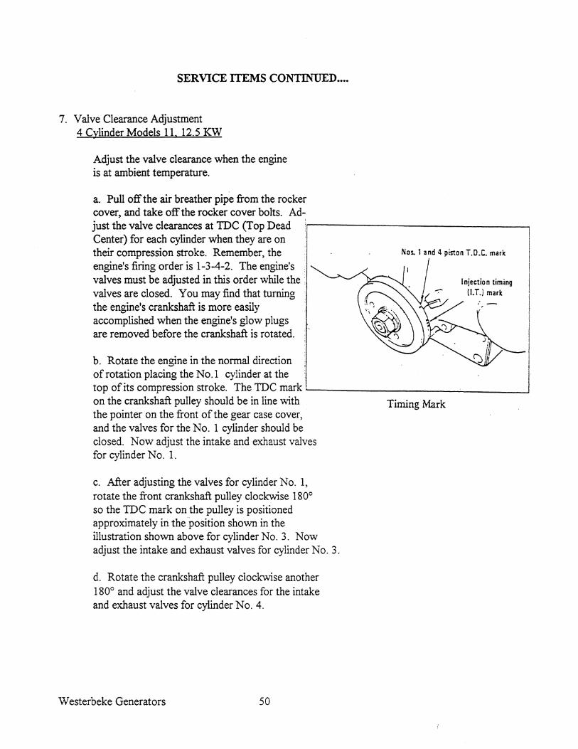
7 . Valve Clearance Adjustment 4 Cylinder Models 11. 12.5 KW
Adjust the valve clearance when the engine is at ambient temperature.
a. Pull off the air breather pipe from the rocker cover, and take off the rocker cover bolts. Ad-just the valve clearances at TOC (Top Dead :r------------------, Center) for each cylinder when they are on their compression stroke. Remember, the engine's firing order is 1-3-4-2. The engine's valves must be adjusted in this order while the : valves are closed. You may find that turning the engine's crankshaft is more easily accomplished when the engine's glow plugs are removed before the crankshaft is rotated.
b. Rotate the engine in the normal direction of rotation placing the No.1 cylinder at the
Nos. 1 and 4 piston T.O.C. mark
I njectio n timing !I.T.i mark
top of its compression stroke. The TOe mark ----------------'---__ ---.J
on the crankshaft pulley should be in line with the pointer on the front of the gear case cover, . and the valves for the No.1 cylinder should be closed. Now adjust the intake and exhaust valves for cylinder No.1.
c. After adjusting the valves for cylinder No.1, rotate the front crankshaft pulley clockwise 1800
so the TOe mark on the pulley is positioned approximately in the position shown in the illustration shown above for cylinder No.3. Now adjust the intake and exhaust valves for cylinder No.3.
d. Rotate the crankshaft pulley clockwise another 1800 and adjust the valve clearances for the intake and exhaust valves for cylinder NO.4.
Westerbeke Generators 50
Timing Mark

SERVICE ITEMS CONTINUED ••••
e. Rotate the crankshaft pulley clockwise another 1800 and adjust the valve clearances for the intake and exhaust valves for cylinder No.2.
Adjust each valve's clearance by inserting a 0.010 inch (0.25 rnm) feeler gauge between the rocker arm and the valve stem .
. 8. Injector Servicing
Injector spray pressure: 1706 psi + 142 psi (120 kglcm2 + 10 kglcm2
Eliminate undesirable injection conditions including after dripping.
Check compression pressure. Remove each glow plug and check each cylinder's compression pressure. The engine's cranking speed is at 250 RPM.
8.0 KW, 10.0 KW, 11.0 KW & 12.5 KW Standard Minimum 455 psi 370 psi (32 kglcm2) (26 kglcm2)
Maximum difference between cylinders: 35.5 psi (2.5 kglcm2)
9. Air Cleaner Element
~~,..,.(-+'\et~:. r<IIi:tf4lol•• ..... ----C1I\ GOOD
Remove the two wing nuts with their washers and remove the rectangular end cover from the intake housing. Pull the air cleaner element PN #039428 out of the housing. Wash this element in a safety kleen solution or mild soapy solution. Squeeze out the solution, rinse and air dry.
Reinstall the element into the housing. Note that the long thin end is down. Be careful not to cause this to fold and jam when inserting. Replace the rectangular end cover and secure with the wind nuts and their washers.
51 Westerbeke Generators
SERVICE ITEMS CONTINUED ••.
NOTE: DO NOT OPERATE THE UNIT WITHOUT THE AIR CLEANER ELEMENT INSTALLED. INTERNAL ENGINE DAMAGE WILL RESULT FROM THE INGESTION OF ROAD DEBRIS.
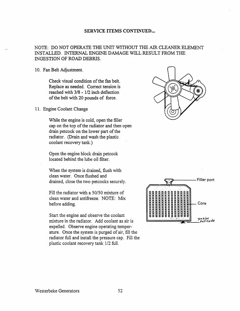
10. Fan Belt Adjustment.
Check visual condition of the fan belt. Replace as needed. Correct tension is reached with 3/8 - 112 inch deflection of the belt with 20 pounds of force.
11. Engine Coolant Change
While the engine is cold, open the filler cap on the top of the radiator and then open drain petcock on the lower part of the radiator. (Drain and wash the plastic coolant recovery tank.)
Open the engine block drain pet cock located behind the lube oil filter.
When the system is drained, flush with clean water. Once flushed and drained, close the two petcocks secureJy.
Fill the radiator with a 50/50 mixture of clean water and antifreeze. NOTE: Mix before adding.
Start the engine and observe the coolant mixture in the radiator. Add coolant as air is expelled. Observe engine operating temperature. Once the system is purged of air, fill the radiator full and install the pressure cap. Fill the plastic coolant recovery tank 112 full.
Westerbeke Generators 52
a-T-.r-----Filler port
Core

SERVICE ITEMS CONTINUED •••••
12. Radiator Pressure Cap Maintenance
Periodically check the condition of the pressure cap. Ensure that the upper and lower rubber seals are in good condition. Check that the vacuum valve manually opens and closes tightly.
13. Generator Adjustments (Hertz/Speed)
Once the diesel generator set has been placed in operation, there maybcfadJiistinents required for engine speed (Hertz) during the engine's break-in period (first 50 hours) or after this period. A no-load voltage adjustment may also be required in conjunction with the engine's speed adjustment.
Frequency is a direct result of engine/generator speed, indicated as follows:
When the generator is run at 1800 rpm, the AC voltage output frequency is 60 Hertz. When the generator is run at 1500 rpm the AC volage output frequency is 50 Hertz.
Therefore, to change the generator's frequency, the generator's speed must be changed.
Adjusting the length of the throttle linkage will effect the no load speed of the engine. Shortening the linkage will increase the speed (hertz) and lengthening the linkage will decrease the speed (Hertz).
14. Generator Maintenance
Keep the generator clean, dry and well ventilated.
Ensure that all connections are clean and tight and that cables carrying AC voltage are properly supported and protected against chafing.
The rear rotor bearing is lubricated and sealed; no maintenance is required. However, if the bearing becomes noisy or rough-sounding, have it replaced.
53 Westerbeke Generators

1 1 BATTERY
SWITCH I I
~ I
120 AMP ICIRCUIT I BREAKER
r 1 EMERGENCY I STOP
r
I SWITCH
1 STOP
: SWITCH
HOURMETER
r
ENGINE DC WIRING SCHEMATIC
PREHEAT SOLENOID r - --I
START
STARTER SOLENOID r - --I
STARTER
r.1 ( I 10 AMP I CIRCUIT
BREAKER
GLOWPLUGS
ALTERNATOR
B
SWITCH K ~ ____ +-________ ~8~6 ~8~5 __________ r-~ ____________ -'
L __ I
: PREHEAT SWITCH
! K I
WATER TEMP. SWITCH
OIL PRESS. GAUGE
OIL PRESS. SWITCH
WATER TEMP. GAUGE
FUEL PUMP
FUEL SOLENOID
VOL TMETER
Westerbeke Generators 54

DC CONTROL CIRCUIT WIRING DIAGRAM
ALTERNATOR 50A WATER TEMPERATURE
llJi.D..E..B. WATER TEMPERATURE
ll.lEli o
~!~ L......!."'IO'-'O,.""--!r B (fJ p
114 PUR
o 114 SRN
.14 RED/PUR r-----.....//~
BATTERY SW ITCH
r ~~ - - - - - - - - --
;_#V\
r:------,~:.---l
;;;
114 RED
.14 PUR/WHT
ZOA CIRCUIT 112R£D --.......~
o 112 YEL/RED
STARTER MOTOR
'14 TAN
114 BLU
114 8RN
114 PUR/lilT
i ~~m. __ ! i""" : dI: = ,,~ ! rc......... ,,, ... I - '"""""""';7iv---
i ~ Nt'" 11 'N,W.' [, ~ "L~·=·~··~·~~~I~~-== __ ~:~""L·-++-~--~"~.Hm •• ~+-~~-+--I .. ~:~
II .. M I L..=__ _ _______ J "410 '
_ ~ trTAKTAn'DI'
~_I
®
GROUND TO ENGINE BLOCK
II~
'" w
'" N .
OIL PRESSURE ll.lEli
• • 5 •
114 ORN r~'I~01'H~T~=j==j----.J 114 PUR 1 1114 elK
~ .\' i , ,
rc 1I,,.j · r----------------M---------------------l
, I"'" -Hm ,,,.; ~ ,.ITeR J J .. t'fCi 1.14'(1
, "-" .• I ~ , , =-~---~I~"=M~-~'----~ ~__ __ __ __J
OIL PRESSURE
o
140RN
I"TEL
WATER. TEMP
o
10 RED/WHT
14 eRN
10 RED
10 RED/WHT . :! PREHEAT
SWITCH
START SWITCH
STOP
HOUR VOLT SWITCH
I
METER METER
L ________________________________________ J
FUEL SOLENOIP=
OIL PRESSURE liI!.liR
FUEL PUMP
INSlBUMENT ~
55 Westerbeke Generators

THIS PAGE LEFT BLANK INTENTIONALLY.
Westerbeke Generators 56

BT GENERATOR
This generator is a Brushless self-excited generator, which requires only the driving force of the engine to produce AC output. The copper and laminated iron in the exciter stator are responsible for the self-exciting feature of this generator. The magnetic field produced causes AC voltage to be induced into the related exciter rotor windings during rotation. Diodes located in the exciter rotor rectify this voltage to DC and supply it to the windings of the rotating field. This creates an electromagnetic field which rotates through the windings of the main stator, inducing an AC voltage which is supplied to a load. A transformer is connected in parallel to the AC output of the main stator. An AC voltage is produced in the auxiliary windings of the transformer and main stator and is, in turn, supplied to a full wave bridge rectifier. The rectifier produces a DC voltage to further excite the exciter stator windings, enabling the generator to produce a rated AC output.
57 Westerbeke Generators

INTERNAL WIRING SCHEMATIC
MODEL 8.0 BTDR (SINGLE PHASE)
r--------------.
: 1 80B : I A I
i I : 1>r 4 3: I I I 2 I L _____________ J
G ORANGE +
GREEN YELLOW
A. Exciter Stator Winding Resistance Valve 10.0 Ohms
B. Exciter Rotor & Field 1. Auxiliary Windings (a-b-c) 2. Diodes (6) 3. Rotating Field Windings 4. Pozi Resistor
C. Main Stator
1. Main Stator Windings 2. Main Stator Windings 3. Main Stator Auxiliary Windings
D. Compound Transfonner 1. Compound Transfonner Windings 2. Compound Transfonner Windings 3. Compound Transfonner Auxiliary Windings
G. Bridge Rectifier
Westerbeke Generators 58

TO FIi!AME
.J!
AC TERMINAL BLOCK CONNECTIONS
120V60Hz
0 U
0
0
N
110/220V SOHz
a:::=:o 0
MODEL 8.0 BTDR (ONLY)
120/240V 60Hz TO FRAME
() 0 0 D
L1 N a
0 0 0
0 0 0 0
ll0V SOHz 22OVSOHz
a=::D 0 a::::D 0
TO "'".Me
o 0 0 000
o a::::D
·,II--!-a:==t5)
N N L,
AC Voltage Connections (12 Stud Terminal Block)
L2
For making connections to the AC terminal block, use terminal ends for #10 studs which will accept #6 or #8 multi-strand wire.
S9 Westerbeke Generators

No Load Voltage Adjustment
Voltage adjustment is made with the compound transformer governing generator regulation.
1. Operate the generator and apply a moderate load momentarily; then remove the load. Note the voltage output from the generator's 120 volt leges). The no-load voltage should be between 121-123 volts at 61.5-62 Hertz.
NOTE: The no load voltage should be adjusted when the generator is started, a momentary load is applied to excite the transformer, and then removed. The voltage produced by the generator after this momentary load is removed is the noload voltage.
2. To raise or lower the voltage, non-conductive shims of varying thickness are inserted or removed from under the laminated steel bar that is situated on top of the compound transformer. The material used for shimming should not soften at temperatures in the 176°F (80°C) range. A small reduction in no-load voltage (1 to 3 Volts) sometimes can be accomplished by gently tapping the top of the laminated steel bar to reduce the air gap between the existing shims and the transformer core.
Westerbeke Generators 60

View of the 8.0 BTDR Generator showing AC terminal Block and compound transformer.
CAUTION: Under no circumstances attempt to increase the no-load voltage by increasing the gap between the laminated steel bar and the transformer core without the use of shims. Magnetic forces created within the transformer during the generator's operation may close the air gap and reduce the no-load voltage output.
3. To remove the laminated steel bar, remove the two upper securing bolts #3 with washer and locks from the compound transformer and lift the bar from the transformer. The addition of shim thickness will raise the no-load voltage and conversely, the removal of shim thickness will lower the no-load voltage.
Varying shim thickness by .001 inch (0.025 mm) will change the no-load voltage by 4 to 6 volts.
61 Westerbeke Generators

INTERNAL WIRING SCHEMATIC SINGLE PHASE GENERATOR
MODELS 10.0 BTDR, 11.0 BTDR AND 12.5 BTDR
r--------, r--------, / I C I I 0 I
A _ r--:--~-8I1-B----;-l-: l! 1 ~ 1 1 1
II :~ 11 2! ! :2 I I I I I 1 I a
- • I 2 I I 3 I :3';;:;~ 1 2 ~ _______________ J I I ~
L. ______ .J
G
FI
+E@
It .. .. .. u
BLtI%
6 lie 6 T 8 E :3 R 2 M
7 I )(
A L
B L 0 e I
® S T
BLtI% U 0
I----------~_~r-. -----------==-=-
•
Fz ,,,-- CItU)l
f--.=-¥. ~ \ YZ!.l.OY
I BU.a:
Bl •• /Yhll. (T. P1A ,e T.rlQ.. :alock.)
Bl,..;rbil.
ltft/Yl>lle
Bl&clc/'Yhit..
J..V.R. PLUG
Black/Thlt.. (To S.l.c"~ awn,ell)
Yallow/Th1le (To a;.l.ct.or ~ ... 1 LCl:t.)
Internal Wiring Schematic
A. Exciter Stator Windings 1 & 2 A -1 and A - 2 Exciter Stator Windings (Selector in CO:MP Position)
B. Exciter Rotor 1. Au.xiliary Windings (a-b-c) 2. Diodes (6) 3. Rotating Field Windings 4. Pozi Resistor
C. Main Stator 1. Main Stator Windings 2. Main Stator Windings 3. Main Stator Au.xiliary Windings
Westerbeke Generators
D. Compound Transformer
1. Compound Transformer Windings 2. Compound Transformer Windings 3. Compound Transformer Auxiliary Windings with VoltagelHertz Connection Bar
F. Selector Switch F-l Compound F-2 Electronic and Compound
G. Bridge Rectifier Wiring
62

AC TERMINAL BLOCK CONNECTIONS MODEL 10.0 BTDR, 11.0 BTDR AND 12.5 BTDR
SINGLE PHASE MODELS
NOTE: We recommend that the installer provide AC amp meters (optional) so that the operator can observe the load being taken ofrom each leg of the generator.
A circuit breaker should be installed between the generator and the AC load. This circuit breaker should be rated for the generators AC output and be able to react quickly to overloads, subject to motor starting considerations:
120V 69Hz 129/248V 69Hz
1\
Os 7
03 8
For making connections to the AC terminal block, use 1/4 inch terminal ends that will accept multi-strand wire sized for the number of conductors in the bundle, the rating of the conductor's insulation, and amperage that will be drawn through the conductor(s). (Refer to the generators data plate for generator amperage ratings).
63 Westerbeke Generators

VIEW OF THE 10.0 BTDR, 11.0 BTDR AND 12.5 BTDR GENERATOR SHOWING THE AC TERMINAL BLOCK AND COMPOUND
TRANSFORMER
No-Load Voltage Adjustment
Voltage adjustment is made with the compound transformer governing generator regulation.
1. The selector switch must be in the COMP position.
2. Operate the generator and apply a moderate load momentarily; then remove the load. Note the voltage output from the generator's 120 Volt leges). The no-load voltage should be between 121-123 volts at 61.5-62 Hertz.
Westerbeke Generators 64

NOTE: The no-load voltage should be adjusted when: the generator is started, a momentary load is applied to excite the transformer, and then removed. The voltage reduced by the generator after this momentary load is removed, is the noload voltage.
3. To raise or lower the voltage, non-conductive shims of varying thickness are inserted or removed from under the laminated steel bar that is situated on top of the compound transformer. The material used for shimming should not soften at temperatures in the 176°F (80°C) range. A small reduction in no-load voltage (1 to 3 Volts) sometimes can be accomplished by gently tapping the top of the laminated steel bar to reduce the air gap between the existing shims and the transformer core.
CAUTION: Under no circumstances attempt to increase the no-load voltage by increasing the gap between the laminated steel bar and the transformer core without the use of shims. Magnetic forces created within the transformer during the generator's operation may close the air gap and reduce the no-load voltage output.
4. To remove the laminated steel bar, remove the two upper securing bolts from the compound transformer and lift the bar from the transformer. The addition of shim thickness will raise the no-load voltage and conversely, the removal of shim thickness will lower the no-load voltage.
Varying shim thickness by .001 inch (0.025 mm) will change the no-load voltage by 4 to 6 volts.
65 Westerbeke Generators
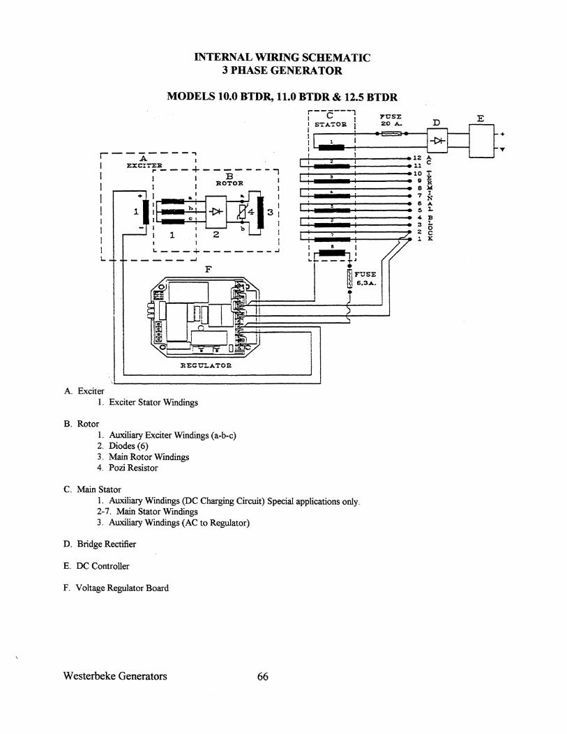
INTERNAL WIRING SCHEMATIC 3 PHASE GENERA TOR
MODELS 10.0 BTDR, 11.0 BTDR & 12.5 BTDR
r--A----~
I ZXCI~:R ___ + _______ -, J I I B I I I I ROTOR I
I +) &I~I I 11: :: -\* 4 3:
1 : 2 b I I I I L. ___ + _______ .J
L. ~ ___ .,...J
F • m FUSE III 6.3A •
•
REGUl.ATOR
A. Exciter 1. Exciter Stator Windings
B. Rotor 1. Auxiliary Exciter Windings (a-b-c) 2. Diodes (6) 3. Main Rotor Windings 4. Pozi Resistor
C. Main Stator 1. Auxiliary Windings (DC Charging Circuit) Special applications only. 2-7. Main Stator Windings 3. Auxiliary Windings (AC to Regulator)
D. Bridge Rectifier
E. DC Controller
F. Voltage Regulator Board
Westerbeke Generators 66
/
LED'S
Red
Green
Yellow Pot en ti orneters
Hz. Axnp.
Sta.b. Volt
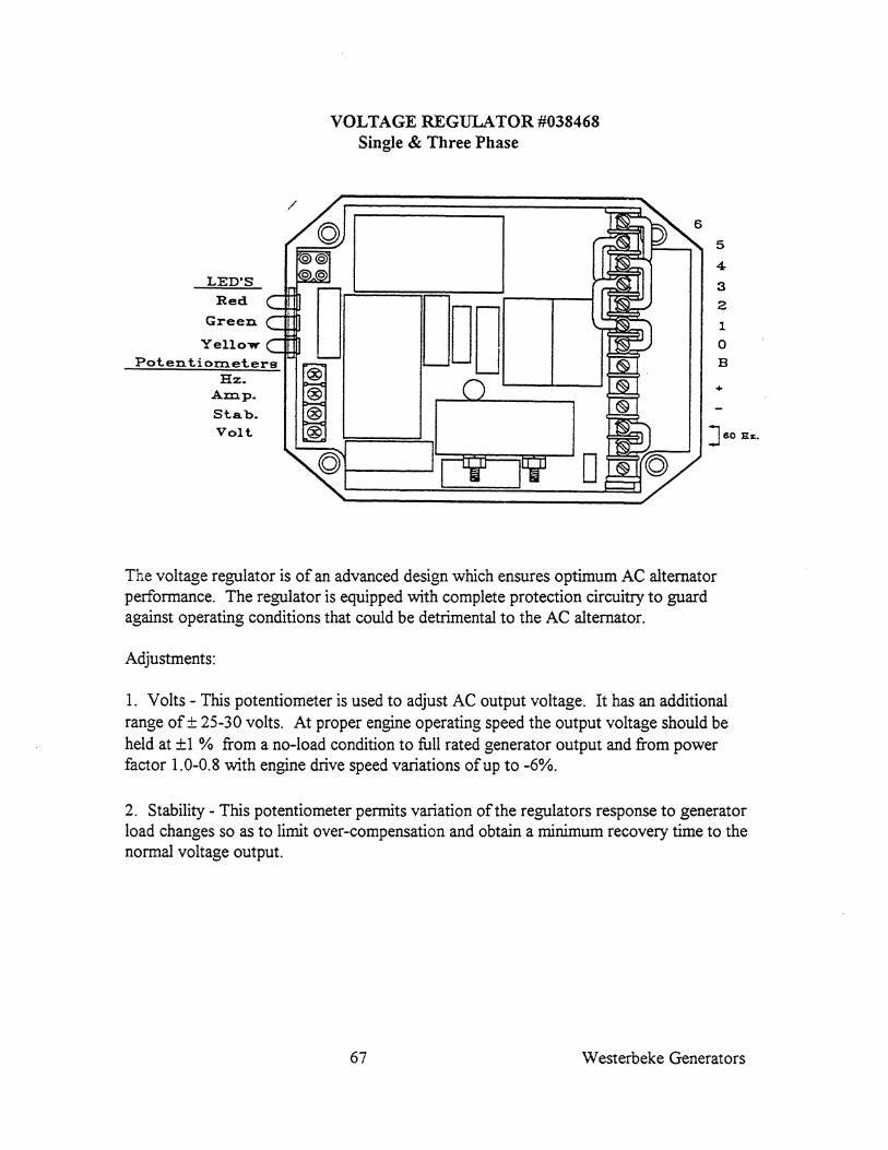
VOLTAGE REGULATOR #038468 Single & Three Phase
0 DOD I
5
4
3
2
1
0
B
+
J60 Bz:.
The voltage regulator is of an advanced design which ensures optimum AC alternator performance. The regulator is equipped with complete protection circuitry to guard against operating conditions that could be detrimental to the AC alternator.
Adjustments:
1. Volts - This potentiometer is used to adjust AC output voltage. It has an additional range of ± 25-30 volts. At proper engine operating speed the output voltage should be held at ±1 % from a no-load condition to full rated generator output and from power factor 1.0-0.8 with engine drive speed variations of up to -6%.
2. Stability - This potentiometer permits variation of the regulators response to generator load changes so as to limit over-compensation and obtain a minimum recovery time to the normal voltage output.
67 Westerbeke Generators
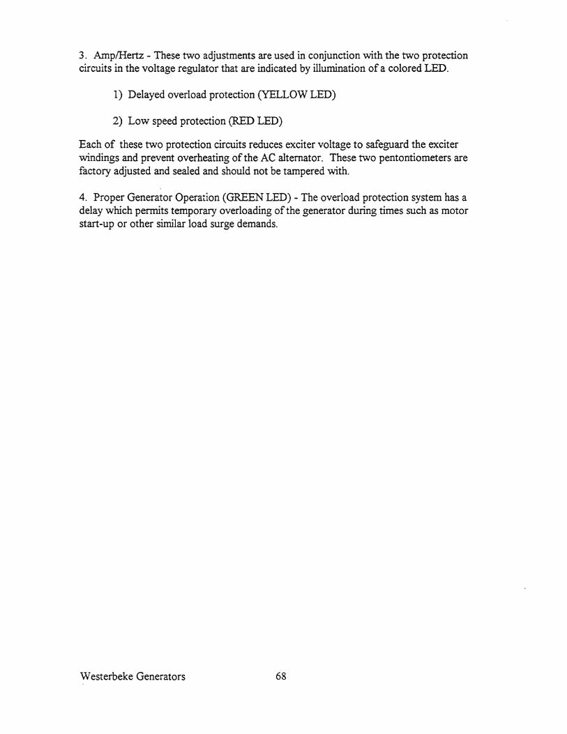
3. AmplHertz - These two adjustments are used in conjunction with the two protection circuits in the voltage regulator that are indicated by illumination of a colored LED.
1) Delayed overload protection (YELLOW LED)
2) Low speed protection (RED LED)
Each of these two protection circuits reduces exciter voltage to safeguard the exciter windings and prevent overheating of the AC alternator. These two pentontiometers are factory adjusted and sealed and should not be tampered with.
4. Proper Generator Operation (GREEN LED) - The overload protection system has a delay which permits temporary overloading of the generator during times such as motor start-up or other similar load surge demands.
Westerbeke Generators 68
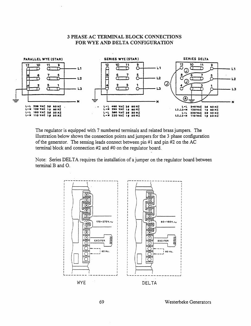
3 PHASE AC TERMINAL BLOCK CONNECTIONS FOR WYE AND DELTA CONFIGURATION
PARALL.EL WYE (STAR) SERIES WYE (STAR) SERIES DElTA
12 10 11 51 .J L.1
12 10 11 SI a:=D lJ--+---L.1 U--+---L.1
8 6 7 5 6 7 5 L2 Cl !) O--+---L.2 o--t---L.2
'" 2 3 , 2 3 1 r- J a=:::D L.3 >-+---L3 o--+---L,3
~~~~I~------N N ~---------N L-L 20. 'lAC ~, &0 HZ L-II 120.,AC I, &OHZ L- L 110 'lAC :S, 10 HZ L-II 11C.,AC t, 10HZ
L-L 460 'lAC ~_ &OKZ L-II 2&1 'lAC I, 60 KZ L-L ~ 'lAC :Sf 10 KZ L-III %%O.,AC 1, 10KZ
L-L 240VAe :s, 60 HZ L2.L:S-N 120.,Ae I, 60 HZ
L-L %20YAe :s, SO HZ L2.L)-N 110VAC I, 10HZ'
The regulator is equipped with 7 numbered terminals and related brass jumpers. The illustration below shows the connection points and jumpers for the 3 phase configuration of the generator. The sensing leads connect between pin #1 and pin #2 on the AC terminal block and connection #2 and #0 on the regulator board.
Note: Series DELTA requires the installation of a jumper on the regulator board between terminal B and O.
r--------------------~ I I I I I I I I I I I I I I
I I I I I I I I I I 170-270V.",
I I
I I I L ___________________ J
WYE
69
I I
r--------------------~ I I I I I I I I I I I I I I
I I I I
80-160V.",
o I I L ___________________ J
DELTA
W esterbeke Generators

The illustration below shows the 3 phase AC generator backend with the louvered covers removed.
Voltage Regulator
Westerbeke Generators 70
DC Charge Bridge Rectifier
AC Terminal Block

TIGHTENING TORQUE CHART
DESCRIPTION
Crankshaft Pulley Nut M-18
Main Bearing Cap Bolts
Connecting Rod Cap Nuts
Flywheel Mounting Bolts
Oil Pan Banjo Drain Bolt
Injection Pump Delivery Valve Holder
Injector Hold Down Bolts
Glow Plug
General Bolts (Bolt Diameter)
M6
M8
MlO
M12
M14
71
TIGHTENING TORQUE KG-M (FT. - LBS)
15-20 (108 - 144.7)
5 - 5.5 (36.2 - 37.8)
3.2 - 3.5 (23.1 - 25.3)
l3-14 (94.0 - 101.3)
5-6 (36.2 - 43)
4-5 (28.9 - 36.2)
1.5 - 2 (10.8 - 14.5)
1.5 - 2 (10.8 - 14.5)
Bolt Head Mark
4 1
0.3 - 0.7 (2.2 - 5.1) 0.8 - 1 (5.8 - 7.2)
1 - 1.3 (7.2 - 9.4) 1.5 - 2.2 (10.8 - 15.9)
1.8 - 2.5 (13.0 - 18.1) 3 - 4.2 (21.7 - 30.4)
3 - 4.2 (21.7 - 30.4) 5.5 - 7.5 (39.8 - 54.2)
5 - 7 (36.2 - 50.6) 8 - 11 (57.9 - 79.6)
Westerbeke Generators

Westerbeke Generators 72