39.1. Design Considerations of Hypersonic Vehicles 39.1.1 ...39.1. Design Considerations of...
12
NPTEL – Aerospace Module-8: Hypersonic vehicle design consideration Lecture: 39: Hypersonic vehicle cooling strategies 39.1. Design Considerations of Hypersonic Vehicles 39.1.1. Major concerns of hypersonic flight The design of a typical hypersonic vehicle can be undertaken by a successful experimental test in a ground based facility. However, design criteria of any flight vehicle are governed by the regime of the flow, which the vehicle is going to encounter. ‘Streamlined body’ is the criterion for design of a subsonic vehicle while ‘reduction of wave drag’ is the criterion for design of a supersonic vehicle. Earlier civil or fighter aircraft and missiles designed all over the globe were based on these themes. Excessive heating is the greatest concern in the design of ballistic missiles and spacecraft, since it could melt their surface. Temperature at the nose of the hypersonic vehicles, flying with the Apollo reentry speed, will be around 11,000 K. Hence, design of hypersonic vehicle is dominated by aerodynamic surface heating where ‘reduction of heat transfer rate’ plays an important role. Allen Julian showed that stagnation point aerodynamic heating varies inversely to the square root of the nose radius. This means the aerodynamic drag coefficient is inversely proportional to the heat load. Therefore, the blunt body configuration, which has a detached shock wave , experiences less heating than the traditional shape with its attached shock wave, is the choice of the hypersonic vehicle. Spacecrafts for the Mercury , Gemini, and Apollo programs were designed using this concept. However the maximum temperature that a space vehicle experiences in its hypersonic flight is far above the maximum sustainable temperature of any material. Hence, a proper heat shield should be designed to withstand the heating loads. Consequently nose bluntness increase the aerodynamic drag experienced by the body. Increase in wave drag is useful during reentry of the spacecraft for aero breaking. Moreover, it is disadvantageous during the ascent stage for a vehicle since increased wave drag demands for more fuel. Therefore, different heat transfer and drag reduction techniques are devised for safer and cheaper hypersonic flight. Joint initiative of IITs and IISc – Funded by MHRD Page 1 of 12
Transcript of 39.1. Design Considerations of Hypersonic Vehicles 39.1.1 ...39.1. Design Considerations of...
NPTEL – Aerospace
Module-8: Hypersonic vehicle design consideration
Lecture: 39: Hypersonic vehicle cooling strategies
39.1. Design Considerations of Hypersonic Vehicles
39.1.1. Major concerns of hypersonic flight
The design of a typical hypersonic vehicle can be undertaken by a successful
experimental test in a ground based facility. However, design criteria of any flight
vehicle are governed by the regime of the flow, which the vehicle is going to
encounter. ‘Streamlined body’ is the criterion for design of a subsonic vehicle while
‘reduction of wave drag’ is the criterion for design of a supersonic vehicle. Earlier
civil or fighter aircraft and missiles designed all over the globe were based on these
themes. Excessive heating is the greatest concern in the design of ballistic missiles
and spacecraft, since it could melt their surface. Temperature at the nose of the
hypersonic vehicles, flying with the Apollo reentry speed, will be around 11,000 K.
Hence, design of hypersonic vehicle is dominated by aerodynamic surface heating
where ‘reduction of heat transfer rate’ plays an important role. Allen Julian showed
that stagnation point aerodynamic heating varies inversely to the square root of the
nose radius. This means the aerodynamic drag coefficient is inversely proportional to
the heat load. Therefore, the blunt body configuration, which has a detached shock
wave, experiences less heating than the traditional shape with its attached shock wave,
is the choice of the hypersonic vehicle. Spacecrafts for the Mercury, Gemini, and
Apollo programs were designed using this concept. However the maximum
temperature that a space vehicle experiences in its hypersonic flight is far above the
maximum sustainable temperature of any material. Hence, a proper heat shield should
be designed to withstand the heating loads. Consequently nose bluntness increase the
aerodynamic drag experienced by the body. Increase in wave drag is useful during
reentry of the spacecraft for aero breaking. Moreover, it is disadvantageous during the
ascent stage for a vehicle since increased wave drag demands for more fuel.
Therefore, different heat transfer and drag reduction techniques are devised for safer
and cheaper hypersonic flight.
Joint initiative of IITs and IISc – Funded by MHRD Page 1 of 12
NPTEL – Aerospace
39.2 Cooling techniques
The cooling techniques to remove thermal energy from the surface of spacecraft are
broadly classified into two categories such as active cooling and passive cooling
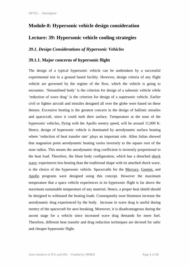
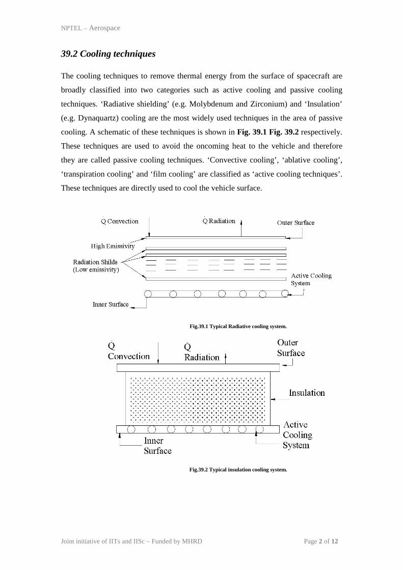
techniques. ‘Radiative shielding’ (e.g. Molybdenum and Zirconium) and ‘Insulation’
(e.g. Dynaquartz) cooling are the most widely used techniques in the area of passive
cooling. A schematic of these techniques is shown in Fig. 39.1 Fig. 39.2 respectively.
These techniques are used to avoid the oncoming heat to the vehicle and therefore
they are called passive cooling techniques. ‘Convective cooling’, ‘ablative cooling’,
‘transpiration cooling’ and ‘film cooling’ are classified as ‘active cooling techniques’.
These techniques are directly used to cool the vehicle surface.
Fig.39.1 Typical Radiative cooling system.
Fig.39.2 Typical insulation cooling system.
Joint initiative of IITs and IISc – Funded by MHRD Page 2 of 12
NPTEL – Aerospace
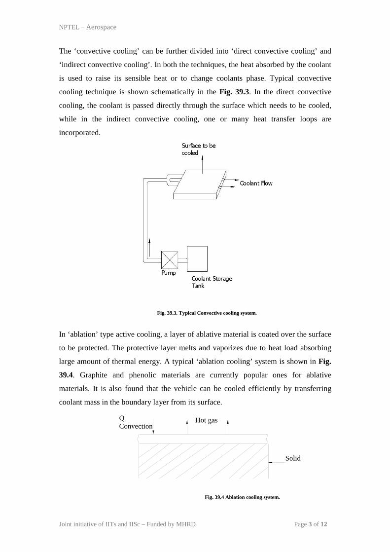
The ‘convective cooling’ can be further divided into ‘direct convective cooling’ and
‘indirect convective cooling’. In both the techniques, the heat absorbed by the coolant
is used to raise its sensible heat or to change coolants phase. Typical convective
cooling technique is shown schematically in the Fig. 39.3. In the direct convective
cooling, the coolant is passed directly through the surface which needs to be cooled,
while in the indirect convective cooling, one or many heat transfer loops are
incorporated.
Fig. 39.3. Typical Convective cooling system.
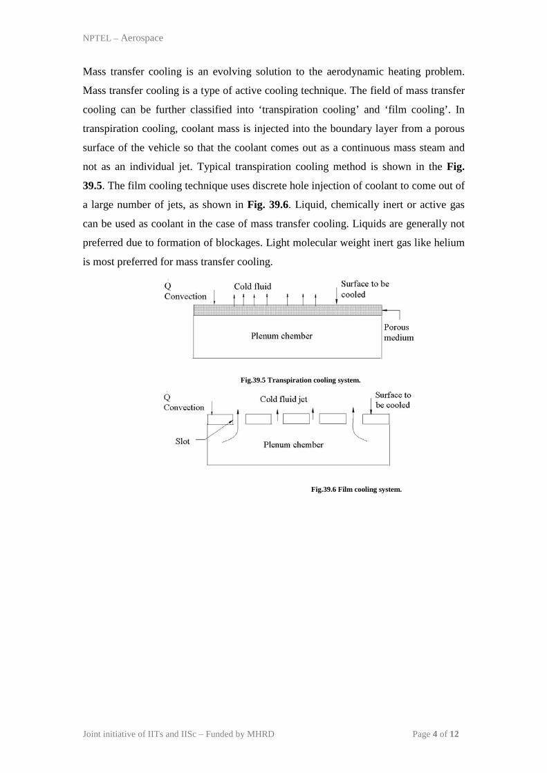
In ‘ablation’ type active cooling, a layer of ablative material is coated over the surface
to be protected. The protective layer melts and vaporizes due to heat load absorbing
large amount of thermal energy. A typical ‘ablation cooling’ system is shown in Fig.
39.4. Graphite and phenolic materials are currently popular ones for ablative
materials. It is also found that the vehicle can be cooled efficiently by transferring
coolant mass in the boundary layer from its surface.
Fig. 39.4 Ablation cooling system.
Hot gas
Solid
Q Convection
Joint initiative of IITs and IISc – Funded by MHRD Page 3 of 12
NPTEL – Aerospace
Mass transfer cooling is an evolving solution to the aerodynamic heating problem.
Mass transfer cooling is a type of active cooling technique. The field of mass transfer
cooling can be further classified into ‘transpiration cooling’ and ‘film cooling’. In
transpiration cooling, coolant mass is injected into the boundary layer from a porous
surface of the vehicle so that the coolant comes out as a continuous mass steam and
not as an individual jet. Typical transpiration cooling method is shown in the Fig.
39.5. The film cooling technique uses discrete hole injection of coolant to come out of
a large number of jets, as shown in Fig. 39.6. Liquid, chemically inert or active gas
can be used as coolant in the case of mass transfer cooling. Liquids are generally not
preferred due to formation of blockages. Light molecular weight inert gas like helium
is most preferred for mass transfer cooling.
Fig.39.5 Transpiration cooling system.
Fig.39.6 Film cooling system.
Joint initiative of IITs and IISc – Funded by MHRD Page 4 of 12
NPTEL – Aerospace
Lecture: 40: Drag reduction methods
40.1 Drag reduction techniques
Imposed bluntness at the nose of the hypersonic vehicle is necessary to alleviate the
oncoming heat load. However, increased wave drag is the immediate consequence of
the forced bluntness. The required fuel of the propulsive vehicle increases due to a
large drag force. It is also observed that a, marginal change in the drag force produces
drastic change in the range of the missile or payload of the vehicle. Therefore,
numerous wave drag reduction techniques are devised.
Joint initiative of IITs and IISc – Funded by MHRD Page 5 of 12
NPTEL – Aerospace
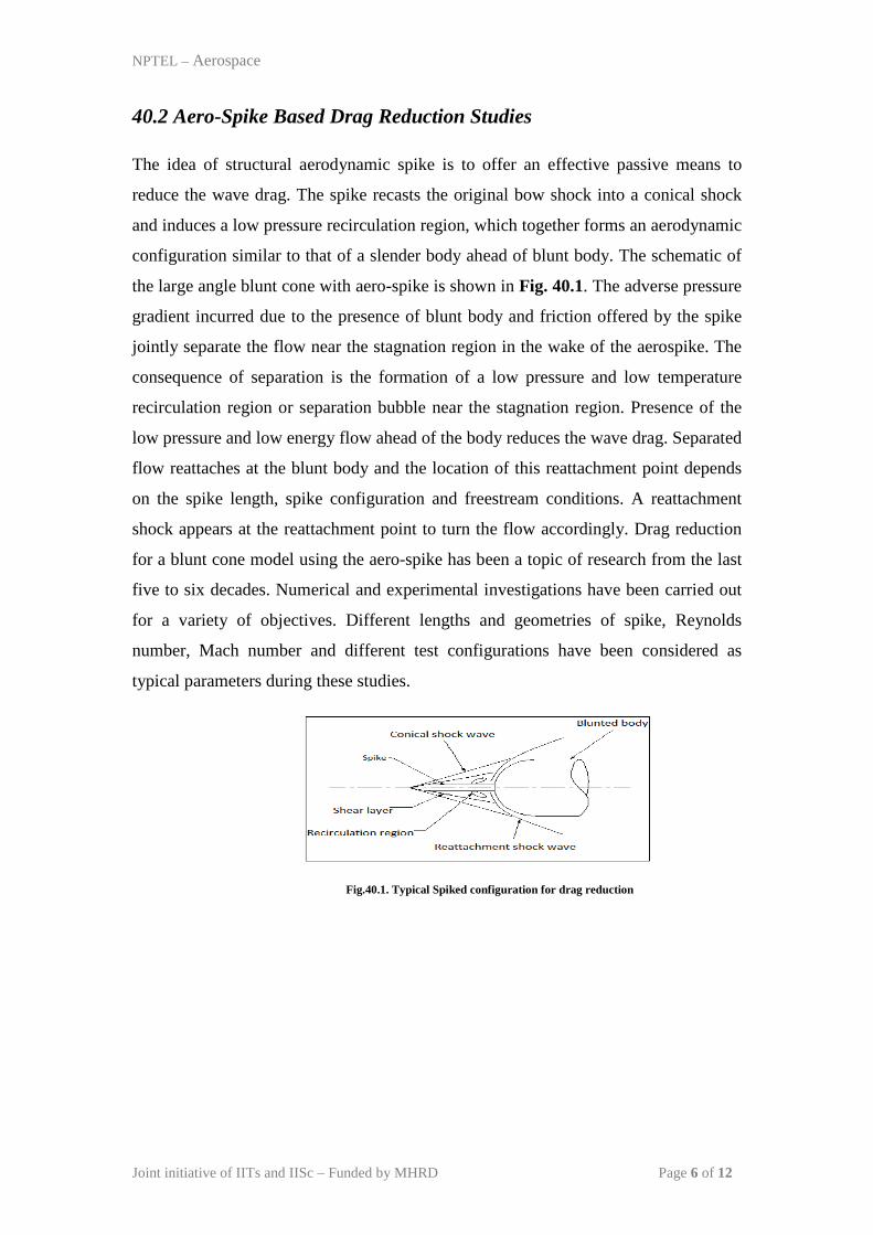
40.2 Aero-Spike Based Drag Reduction Studies
The idea of structural aerodynamic spike is to offer an effective passive means to
reduce the wave drag. The spike recasts the original bow shock into a conical shock
and induces a low pressure recirculation region, which together forms an aerodynamic
configuration similar to that of a slender body ahead of blunt body. The schematic of
the large angle blunt cone with aero-spike is shown in Fig. 40.1. The adverse pressure
gradient incurred due to the presence of blunt body and friction offered by the spike
jointly separate the flow near the stagnation region in the wake of the aerospike. The
consequence of separation is the formation of a low pressure and low temperature
recirculation region or separation bubble near the stagnation region. Presence of the
low pressure and low energy flow ahead of the body reduces the wave drag. Separated
flow reattaches at the blunt body and the location of this reattachment point depends
on the spike length, spike configuration and freestream conditions. A reattachment
shock appears at the reattachment point to turn the flow accordingly. Drag reduction
for a blunt cone model using the aero-spike has been a topic of research from the last
five to six decades. Numerical and experimental investigations have been carried out
for a variety of objectives. Different lengths and geometries of spike, Reynolds
number, Mach number and different test configurations have been considered as
typical parameters during these studies.
Fig.40.1. Typical Spiked configuration for drag reduction
Joint initiative of IITs and IISc – Funded by MHRD Page 6 of 12
NPTEL – Aerospace
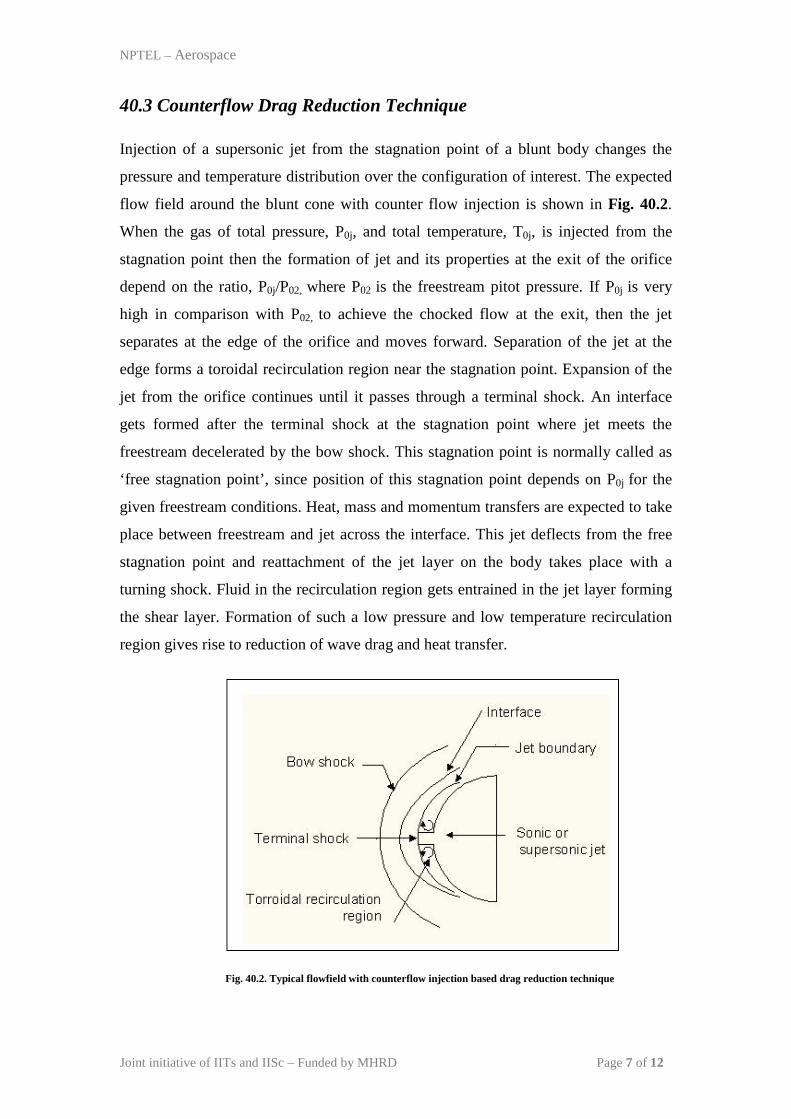
40.3 Counterflow Drag Reduction Technique
Injection of a supersonic jet from the stagnation point of a blunt body changes the
pressure and temperature distribution over the configuration of interest. The expected
flow field around the blunt cone with counter flow injection is shown in Fig. 40.2.
When the gas of total pressure, P0j, and total temperature, T0j, is injected from the
stagnation point then the formation of jet and its properties at the exit of the orifice
depend on the ratio, P0j/P02, where P02 is the freestream pitot pressure. If P0j is very
high in comparison with P02, to achieve the chocked flow at the exit, then the jet
separates at the edge of the orifice and moves forward. Separation of the jet at the
edge forms a toroidal recirculation region near the stagnation point. Expansion of the
jet from the orifice continues until it passes through a terminal shock. An interface
gets formed after the terminal shock at the stagnation point where jet meets the
freestream decelerated by the bow shock. This stagnation point is normally called as
‘free stagnation point’, since position of this stagnation point depends on P0j for the
given freestream conditions. Heat, mass and momentum transfers are expected to take
place between freestream and jet across the interface. This jet deflects from the free
stagnation point and reattachment of the jet layer on the body takes place with a
turning shock. Fluid in the recirculation region gets entrained in the jet layer forming
the shear layer. Formation of such a low pressure and low temperature recirculation
region gives rise to reduction of wave drag and heat transfer.
Fig. 40.2. Typical flowfield with counterflow injection based drag reduction technique
Joint initiative of IITs and IISc – Funded by MHRD Page 7 of 12
NPTEL – Aerospace
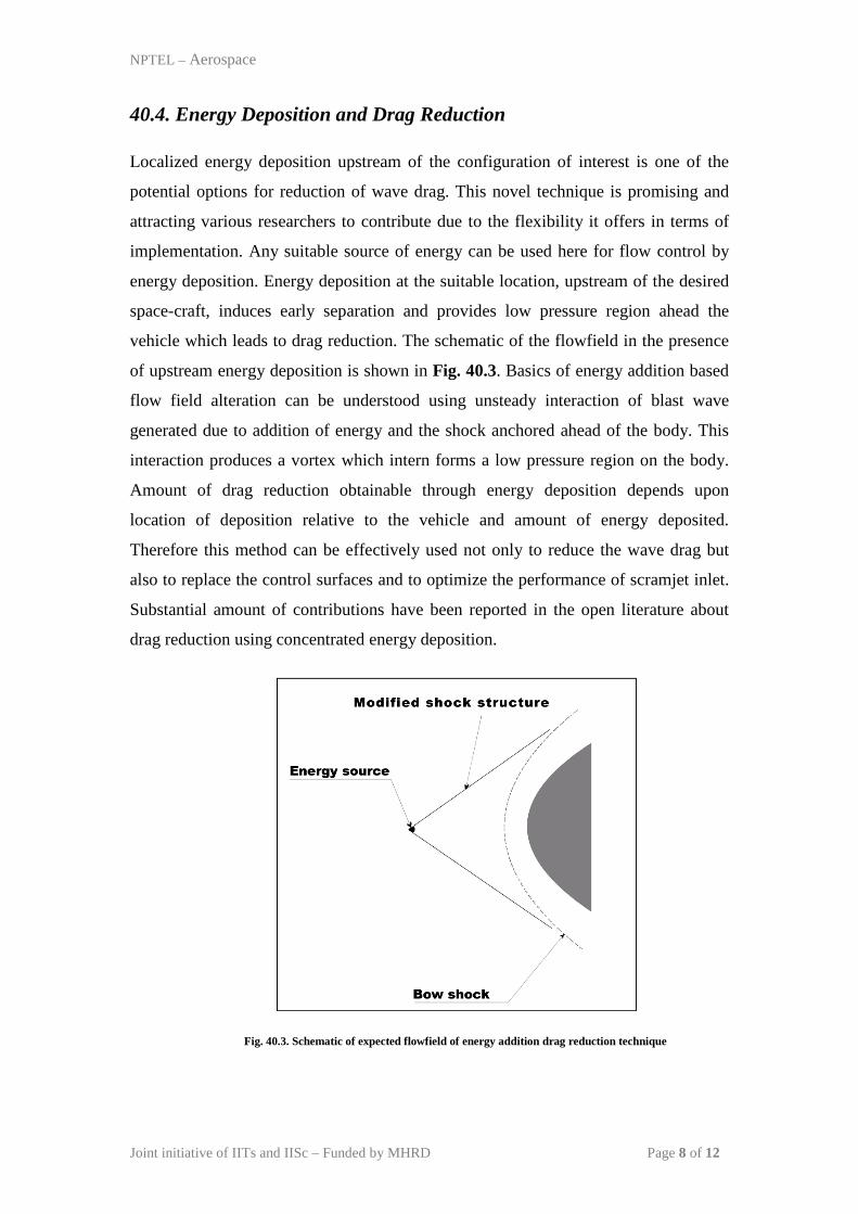
40.4. Energy Deposition and Drag Reduction
Localized energy deposition upstream of the configuration of interest is one of the
potential options for reduction of wave drag. This novel technique is promising and
attracting various researchers to contribute due to the flexibility it offers in terms of
implementation. Any suitable source of energy can be used here for flow control by
energy deposition. Energy deposition at the suitable location, upstream of the desired
space-craft, induces early separation and provides low pressure region ahead the
vehicle which leads to drag reduction. The schematic of the flowfield in the presence
of upstream energy deposition is shown in Fig. 40.3. Basics of energy addition based
flow field alteration can be understood using unsteady interaction of blast wave
generated due to addition of energy and the shock anchored ahead of the body. This
interaction produces a vortex which intern forms a low pressure region on the body.
Amount of drag reduction obtainable through energy deposition depends upon
location of deposition relative to the vehicle and amount of energy deposited.
Therefore this method can be effectively used not only to reduce the wave drag but
also to replace the control surfaces and to optimize the performance of scramjet inlet.
Substantial amount of contributions have been reported in the open literature about
drag reduction using concentrated energy deposition.
Fig. 40.3. Schematic of expected flowfield of energy addition drag reduction technique
Joint initiative of IITs and IISc – Funded by MHRD Page 8 of 12
NPTEL – Aerospace
Lecture: 41: Hypersonic flight parameters and stability
41.1 Design Parameters of Flight
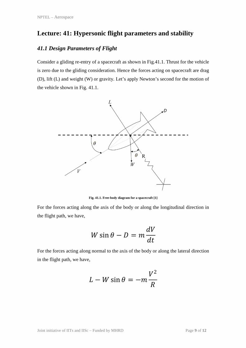
Consider a gliding re-entry of a spacecraft as shown in Fig.41.1. Thrust for the vehicle
is zero due to the gliding consideration. Hence the forces acting on spacecraft are drag
(D), lift (L) and weight (W) or gravity. Let’s apply Newton’s second for the motion of
the vehicle shown in Fig. 41.1.
Fig. 41.1. Free-body diagram for a spacecraft [1]
For the forces acting along the axis of the body or along the longitudinal direction in
the flight path, we have,
𝑊𝑊 sin𝜃𝜃 − 𝐷𝐷 = 𝑚𝑚𝑑𝑑𝑑𝑑𝑑𝑑𝑑𝑑
For the forces acting along normal to the axis of the body or along the lateral direction
in the flight path, we have,
𝐿𝐿 −𝑊𝑊 sin𝜃𝜃 = −𝑚𝑚𝑑𝑑2
𝑅𝑅
Joint initiative of IITs and IISc – Funded by MHRD Page 9 of 12
NPTEL – Aerospace
Above equations of the motion can be simplified for the actual flight conditions where
θ is very small. This approximation leads to sin(θ)~0 and cos(θ )~1. Therefore,
−𝐷𝐷 =𝑊𝑊𝑔𝑔𝑑𝑑𝑑𝑑𝑑𝑑𝑑𝑑
𝐿𝐿 −𝑊𝑊 = −𝑊𝑊𝑔𝑔𝑑𝑑2
𝑅𝑅
Drag and Lift force can be expressed in terms of non-dimensional coefficients as,
2(1/ 2)DDC
V Sρ= and 2(1/ 2)L
LCV Sρ
=
Here S is the projected or reference area. Hence the equation of motion can be further
re-written for axial direction as,
−12𝜌𝜌𝑑𝑑2𝑆𝑆𝐶𝐶𝐷𝐷 =
𝑊𝑊𝑔𝑔𝑑𝑑𝑑𝑑𝑑𝑑𝑑𝑑
− 1𝑔𝑔𝑑𝑑𝑑𝑑𝑑𝑑𝑑𝑑
= � 𝑊𝑊𝐶𝐶𝐷𝐷𝑆𝑆
�−1 𝜌𝜌𝑑𝑑2
2 (41.1)
The similar expression for the normal direction is as,
12𝜌𝜌𝑑𝑑
2𝑆𝑆𝐶𝐶𝐿𝐿 −𝑊𝑊 = −𝑊𝑊𝑔𝑔𝑑𝑑2
𝑅𝑅
1 − 1𝑔𝑔𝑑𝑑2
𝑅𝑅= � 𝑊𝑊
𝐶𝐶𝐿𝐿𝑆𝑆�−1 𝜌𝜌𝑑𝑑2
2 (41.2)
These equations (41.1) and (41.2) assert that the parameters D
WC S
and L
WC S
are very
important for the estimation of the flight path of a re-entry vehicle. Therefore
velocity-altitude map is generally plotted for any flight. Vehicles with higher value of
these coefficients encounter higher penetration in the active atmosphere before larger
Joint initiative of IITs and IISc – Funded by MHRD Page 10 of 12
NPTEL – Aerospace
deceleration. The parameter D
WC S
is found to be important for ballistic re-entry while
L
WC S
turns out to be an important parameter for lifting re-entry.
41.2 Stability and Stability Margin
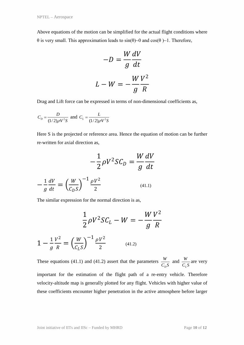
Force incurred by the aircraft during motion can be considered as a non-uniform
distribution of pressure (inviscid) and shear (viscous) forces. The resultant force of all
these forces passes through and can be termed as the centre of pressure. The
terminology ‘centre of pressure’ can be felt due to the dominance of the pressure force
in the presence of shock wave. This resultant force is invariantly expressed in terms of
its components. However two systems are followed while expressing the resultant in
terms of the components as shown in Fig. 41.2. If we consider the body or object or
space craft as the basis of the co-ordinate system then the components are called as
axial (along the axis of the object) and normal (along the direction, normal to the axis
of the object). However, if we consider the trajectory or flight path as the basis of the
co-ordinate system then the components, then the resultant is decomposed with
respect to the velocity. Thus represented component of force parallel to the velocity is
called as drag force and normal to it is called as lift force.
Fig. 41.2. Free-body diagram for a spacecraft in different co-ordinate systems.
Joint initiative of IITs and IISc – Funded by MHRD Page 11 of 12
NPTEL – Aerospace
Position of the ‘centre of pressure’ or ‘centre of force’ relative to the centre of gravity
is an important parameter for stability of the flight and hence for the mission. Static
margin of the flight is defined as,
cp cgStatic Margin=x x
L−
Vehicle is said to be statically stable is centre of pressure and centre of gravity lie at
the same distance from the leading edge of the vehicle i.e. cp cgx x= . Static margin is
invariantly kept positive by placing centre of pressure positioned as shown in Fig.41.2
and is generally 3-5% of the characteristic length (L) of the aircraft. The imposed
positivity of the static margin maintains stability by producing a restoring couple
since both the components of the axial force provide the pitching moment. In case of
increase in angle of attack of the vehicle in the presence of any disturbance, drag force
increases. Thus increased drag force leads to increase in the anti-clock wise pitching
moment. This increased pitching moment acts as the restoring moment by keep the
nose or leading edge of the vehicle down.
Joint initiative of IITs and IISc – Funded by MHRD Page 12 of 12