3900/3900P Pulse Oximeter - Frank's Hospital Workshop · GE Healthcare 3900/3900P Pulse Oximeter...
107
GE Healthcare 3900/3900P Pulse Oximeter TruTrak®+ User’s Manual ♥
Transcript of 3900/3900P Pulse Oximeter - Frank's Hospital Workshop · GE Healthcare 3900/3900P Pulse Oximeter...

GE Healthcare
3900/3900P Pulse OximeterTruTrak®+
User’s Manual

GE Healthcare
3900/3900P Pulse OximeterTruTrak®+
User’s Manual
6050-0006-406March 2005
Important
Rx Only (USA)
Attention! Consult the accompanying instructions before using thisdevice.
The safety, reliability, and performance of this device can be assured only underthe following conditions:
• If it is used according to the accompanying operating instructions.
• If fittings, extensions, readjustments, changes, or repairs are carried out byagents authorized by Datex-Ohmeda.
• If it is used in buildings having ground equalization wiring that complies withrelevant local standards and regulations.
This device must be cleaned and checked periodically. Do not use a defectivedevice. Parts that are broken, missing, plainly worn, distorted, or contaminatedshould be replaced immediately. If repair or replacement becomes necessary,request service advice from Datex-Ohmeda. Do not repair this device or any of itsparts other than in accordance with written instructions provided by Datex-Ohmeda.
The user of this device shall have the sole responsibility for any malfunction thatresults from improper use, faulty maintenance, improper repair, unauthorizedservice, damage, or alteration by anyone other than Datex-Ohmeda.
TrademarksDatex®, Ohmeda®, OxyTip®, PerfTrak®, TeleOximetry®, TruTrak®, and PIr® arethe property of GE Healthcare Finland Oy. All other product and company namesare the property of their respective owners.
0537
GE Healthcare Finland OyHelsinki, Finland+358 10 394 11www.gehealthcare.com
© 2005 General Electric Company. All rights reserved.

Table of Contents
i
1/OverviewProduct description.....................................................................................................................................1-1
Intended use........................................................................................................................................1-1TruTrak+ technology.......................................................................................................................1-1PIr pulsatile value............................................................................................................................1-2Other features.....................................................................................................................................1-2Functional components................................................................................................................1-3Principles of operation..................................................................................................................1-4
Calibration..............................................................................................................................1-5
Front panel .......................................................................................................................................................1-6Alarm silence button......................................................................................................................1-7
Alarm silence........................................................................................................................1-7All mute....................................................................................................................................1-7
Numeric display...............................................................................................................................1-7Graphic display.................................................................................................................................1-8SpO2 alarm limits, high and low............................................................................................1-9Pulse rate alarm limits, high and low..................................................................................1-9Display contrast adjuster..............................................................................................................1-9Power/Standby button/AC power light ..............................................................................1-9
Battery operation.................................................................................................................1-9Carrying handle.............................................................................................................................1-10Sensor connector...........................................................................................................................1-10Screen option buttons.................................................................................................................1-10Pulse beep volume button.......................................................................................................1-11Alarm volume button..................................................................................................................1-11Printer ..................................................................................................................................................1-11
Rear panel......................................................................................................................................................1-12Power entry module....................................................................................................................1-12Equipotential ground connector...........................................................................................1-12Product information label ........................................................................................................1-12Mode Switch....................................................................................................................................1-12RS-232 serial/analog connector.............................................................................................1-12
Precautions....................................................................................................................................................1-13Warnings............................................................................................................................................1-13
Failure of operation........................................................................................................1-13Data validity........................................................................................................................1-13Explosion hazard..............................................................................................................1-13Electrical shock hazard................................................................................................1-13Electrical shock and flammability hazard........................................................1-14Patient safety.......................................................................................................................1-14Patient safety (sensors) ..................................................................................................1-14Patient safety (modem).................................................................................................1-14RS-232 system interconnection................................................................................1-15
Cautions..............................................................................................................................................1-15Handle the monitor with care..................................................................................1-15Cleaning................................................................................................................................1-15Sensors...................................................................................................................................1-15Battery.....................................................................................................................................1-15Printer.....................................................................................................................................1-15Disposal..................................................................................................................................1-15

Table of Contents
ii
2/Setup and OperationsPowering the oximeter...............................................................................................................................2-1
Setup....................................................................................................................................................................2-2Factory settings..................................................................................................................................2-2
Before powering on the oximeter..............................................................................2-2After powering on the oximeter.................................................................................2-2
Mode switch settings......................................................................................................................2-3Language selection.............................................................................................................2-3Averaging mode...................................................................................................................2-4PIr pulsatile value display.............................................................................................2-4EMI line frequency............................................................................................................2-4
Checkout procedure...................................................................................................................................2-5
Signal and data validity............................................................................................................................2-8Plethysmographic waveform.....................................................................................................2-8
Low perfusion.......................................................................................................................2-8Signal noise............................................................................................................................2-9
Numeric display............................................................................................................................2-10SpO2........................................................................................................................................2-10Pulse rate..............................................................................................................................2-10PIr pulsatile value............................................................................................................2-10
Waveform screen button.......................................................................................................................2-11
Menu button.................................................................................................................................................2-11Main menu function key buttons.........................................................................................2-11
LABELS............................................................................................................................................................2-12Summary: custom patient labels...........................................................................2-12
Select field function keys................................................................................2-13– / + Select character function keys....................................................................2-13
Function key...........................................................................................................2-13CLEAR....................................................................................................................................2-14
Locking label lines........................................................................................................................2-14
SETTINGS.....................................................................................................................................................2-15SAVE LIMITS.....................................................................................................................2-15ALL MUTE...........................................................................................................................2-16BAUD RATE........................................................................................................................2-16ANALOG...............................................................................................................................2-16MODE.....................................................................................................................................2-16OUTPUT...............................................................................................................................2-16CONTRAST (3900P printer only) ...........................................................................2-16
Date and time...............................................................................................................................................2-17Date..........................................................................................................................................2-17Time.........................................................................................................................................2-17
Trend options...............................................................................................................................................2-18Trend function keys.....................................................................................................................2-19
Scroll buttons.........................................................................................................2-19 Shift buttons...................................................................................................2-19
CLEAR....................................................................................................................................2-19Viewing time scale for display.................................................................................2-20
Trend data.........................................................................................................................................2-20
Patient function key lockout...............................................................................................................2-22
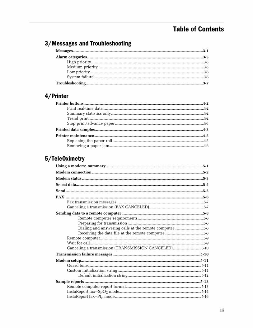
Table of Contents
iii
3/Messages and TroubleshootingMessages.............................................................................................................................................................3-1
Alarm categories............................................................................................................................................3-5High priority........................................................................................................................................3-5Medium priority................................................................................................................................3-5Low priority.........................................................................................................................................3-6System failure.....................................................................................................................................3-6
Troubleshooting.............................................................................................................................................3-7
4/PrinterPrinter buttons................................................................................................................................................4-2
Print real-time data..........................................................................................................................4-2Summary statistics only................................................................................................................4-2Trend print...........................................................................................................................................4-2Stop print/advance paper...........................................................................................................4-3
Printed data samples..................................................................................................................................4-3
Printer maintenance...................................................................................................................................4-5Replacing the paper roll ..............................................................................................................4-5Removing a paper jam..................................................................................................................4-6
5/TeleOximetryUsing a modem: summary.....................................................................................................................5-1
Modem connection......................................................................................................................................5-2
Modem status..................................................................................................................................................5-3
Select data.........................................................................................................................................................5-4
Send......................................................................................................................................................................5-5
FAX.......................................................................................................................................................................5-6Fax transmission messages.........................................................................................................5-7Canceling a transmission (FAX CANCELED)..................................................................5-7
Sending data to a remote computer..................................................................................................5-8Remote computer requirements................................................................................5-8Preparing for transmission............................................................................................5-8Dialing and answering calls at the remote computer...................................5-8Receiving the data file at the remote computer...............................................5-8
Remote computer.............................................................................................................................5-9Wait for call .........................................................................................................................................5-9Canceling a transmission (TRANSMISSION CANCELED)..................................5-10
Transmission failure messages..........................................................................................................5-10
Modem setup................................................................................................................................................5-11Guard tone.........................................................................................................................................5-11Custom initialization string.....................................................................................................5-11
Default initialization string.........................................................................................5-12
Sample reports............................................................................................................................................5-13Remote computer report format...........................................................................................5-13InstaReport fax—SpO2 mode...................................................................................................5-14InstaReport fax—PIr mode........................................................................................................5-16

Table of Contents
iv
6/Maintenance and ServiceCleaning.............................................................................................................................................................6-1
Oximeter (with or without the printer) ...............................................................................6-1
Recharging the battery..............................................................................................................................6-2
Replacing the battery.................................................................................................................................6-2
Replacing the fuses.....................................................................................................................................6-3
Repair policy and procedure.................................................................................................................6-4Packaging and return procedure............................................................................................6-4
Parts list ..............................................................................................................................................................6-5
7/Compliance and SpecificationsCompliance with standards....................................................................................................................7-1
General safety requirements......................................................................................................7-1Electromagnetic compatibility (EMC)..................................................................................7-2
Electromagnetic effects....................................................................................................7-2Safety checks for software...........................................................................................................7-2
Specifications..................................................................................................................................................7-3Circuitry.................................................................................................................................................7-3Audio indicators................................................................................................................................7-3Audible alarms..................................................................................................................................7-3
Alarm limits ...........................................................................................................................7-3Displays..................................................................................................................................................7-4Mode switch........................................................................................................................................7-4SpO2.........................................................................................................................................................7-4
Interfering substances......................................................................................................7-4Pulse rate...............................................................................................................................................7-5PIr pulsatile value............................................................................................................................7-5Sensor emitter wavelength ranges.........................................................................................7-5Environmental....................................................................................................................................7-5Electrical................................................................................................................................................7-5
Battery........................................................................................................................................7-5Power.........................................................................................................................................7-6Current leakage....................................................................................................................7-6Fuses...........................................................................................................................................7-6
RS-232 serial/analog connector................................................................................................7-6Serial output ..........................................................................................................................7-6Analog output........................................................................................................................7-6
Dimensions and weight ................................................................................................................7-6
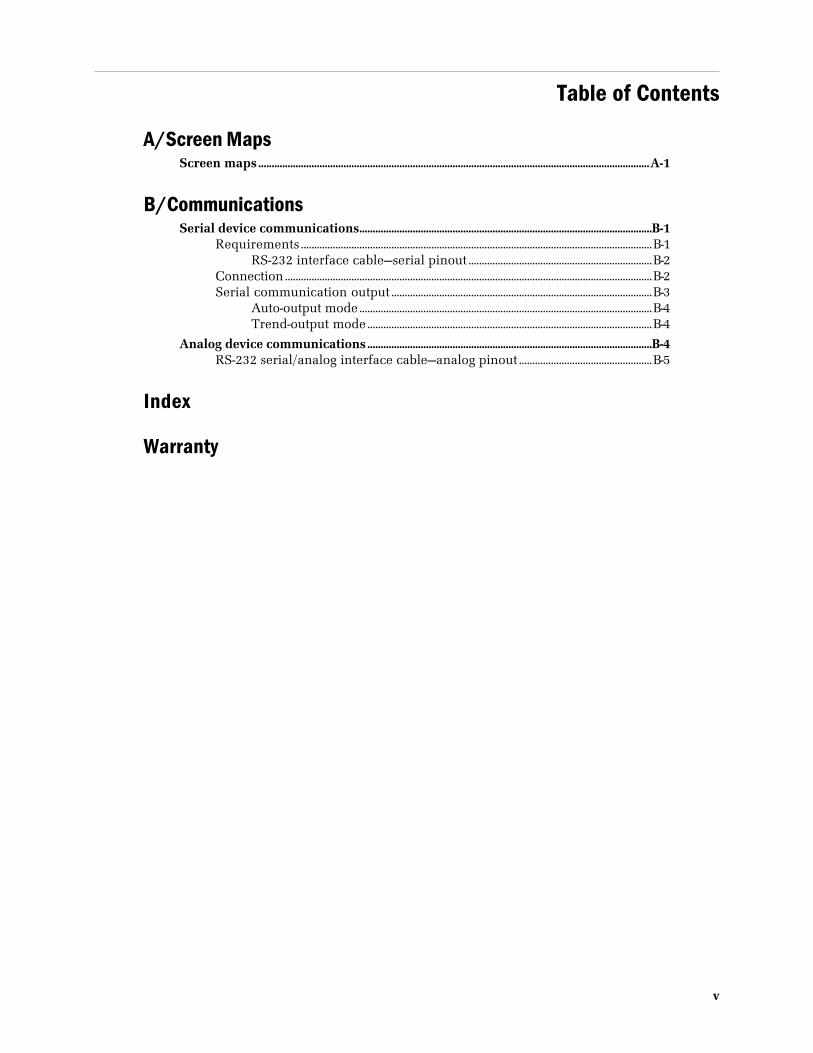
Table of Contents
v
A/Screen MapsScreen maps...................................................................................................................................................A-1
B/CommunicationsSerial device communications..............................................................................................................B-1
Requirements....................................................................................................................................B-1RS-232 interface cable—serial pinout .....................................................................B-2
Connection..........................................................................................................................................B-2Serial communication output ..................................................................................................B-3
Auto-output mode..............................................................................................................B-4Trend-output mode...........................................................................................................B-4
Analog device communications...........................................................................................................B-4RS-232 serial/analog interface cable—analog pinout ..................................................B-5
Index
Warranty

List of Figures
vi
Name Page
Figure 1-1. Signal processing block diagram...........................................................................1-3Figure 1-2. Comparative light absorption...................................................................................1-4Figure 1-3. Extinction versus wavelength graph....................................................................1-4Figure 1-4. 3900P Pulse Oximeter front panel.........................................................................1-6Figure 1-5. 3900/3900P Pulse Oximeter rear panel ...........................................................1-12
Figure 2-1. Typical adult plethysmographic waveform.....................................................2-8Figure 2-2. Typical neonate plethysmographic waveform...............................................2-8Figure 2-3. Low perfusion waveform............................................................................................2-9Figure 2-4. Noisy plethysmographic waveform......................................................................2-9Figure 2-5. Main menu.......................................................................................................................2-11Figure 2-6. LABELS screen..............................................................................................................2-13Figure 2-7. Settings screen options..............................................................................................2-15Figure 2-8. DATE/TIME screen......................................................................................................2-17Figure 2-9. Trend screens.................................................................................................................2-18
Figure 4-1. 3900P printer......................................................................................................................4-2Figure 4-2. SELECT HOURS screen.............................................................................................4-2Figure 4-3. Printed data samples.....................................................................................................4-4Figure 4-4. Replacing the paper roll .............................................................................................4-5Figure 4-5. Removing the paper-feed cover..............................................................................4-6
Figure 5-1. MODEM STATUS screen...........................................................................................5-3Figure 5-2. SELECT HOURS screen.............................................................................................5-4Figure 5-3. SEND screen......................................................................................................................5-5Figure 5-4. PHONE NUMBER screen..........................................................................................5-6Figure 5-5. SENDING FAX screen..................................................................................................5-7Figure 5-6. SENDING DATA screen..............................................................................................5-9Figure 5-7. MODEM SETUP screen............................................................................................5-11Figure 5-8. INITIALIZATION STRING screen......................................................................5-12
1-1
1/OverviewThis chapter
• Introduces the product, including the principles of its operation.
• Describes the oximeter’s controls and features.
• Lists the precautions you must take when using the oximeter.
Product descriptionThe Datex-Ohmeda Model 3900 and Model 3900P pulse oximeters with TruTrak®+technology feature two easy-to-read displays that present patient data and statusinformation.
• The numeric display shows the SpO2 and pulse rate values.
• The graphic display shows the plethysmographic waveform (or trend data),messages, the Relative Perfusion Index (PIr®) pulsatile value, and the highand low alarm limit settings for SpO2 and pulse rate.
You can send current or trend data (SpO2 or PIr pulsatile value) to the built-inprinter (3900P only) and to a computer. You can connect a modem to the monitorand use the TeleOximetry® feature to transmit data to a fax machine or computer.You can also set the date and time and create labels for individual data records.
Intended useThe 3900/3900P pulse oximeter with TruTrak+ technology is indicated for spot-checking and continuous monitoring of functional oxygen saturation and pulserate, including monitoring during conditions of clinical patient motion.1 Thisdevice is intended for use with adult, pediatric, and neonatal patients in bothhospital and non-hospital environments.
Important: Only OxyTip®+ sensors can be used with this monitor.
TruTrak+ technology TruTrak+ technology improves pulse oximetry performance during conditions ofclinical patient motion. In the clinical environment, oximetry readings are affectedby several types of patient motion. The types of motion include clenching,pressing, and rubbing as well as extending, flexing, and kicking. Unlike motiontechnologies that use only a single method to correct for motion, TruTrak+ selects
1 Anesthesia & Analgesia. 2002;94,1S, S54-S60
3900/3900P User’s Manual
1-2
one of many proprietary motion-correction algorithms, depending on the type andintensity of the motion.
TruTrak+ technology employs a patented five-step process that consists of1) high-speed data sampling; 2) motion identification, quantification, andcorrection; 3) calculation of the SpO2 value; 4) weighting and averaging of theSpO2 value; and 5) the display of an improved SpO2 value. The result of thisprocess is a more accurate and stable displayed SpO2 value, with fewer falsealarms or dashed displays.
Important: For TruTrak+ performance, the averaging mode must be set to Long.See Setup in chapter 2.
PIr pulsatile valueThe PIr pulsatile value indicates the strength of the pulse signal at the sensor site:the higher the PIr value, the stronger the pulse signal. A strong pulse signalincreases the validity of SpO2 and pulse rate data.
PIr is a relative value that varies from patient to patient. Clinicians can use the PIrvalue to compare the strength of the pulse signal at different sites on a patient inorder to locate the best site for the sensor (the site with the strongest pulse signal).
You can choose to display or not display the PIr value (see Setup in chapter 2).
Other features• PerfTrak® waveform display, an automatic scale of the plethysmographic
waveform to provide a relative indication of the sensor site perfusion level.
• Large SpO2 digital display for clear differentiation from the pulse rate value.
• Backlit display and contrast control for excellent visibility in subdued lightingconditions; adjustable viewing angle, using the pull-down feet under themonitor.
• Direct access to user-selectable high and low alarm limits for SpO2 and pulserate.
• An audible pulse indicator with an adjustable volume; the automatic pitchmodulation reflects changing SpO2 level.
• Visual and audible (adjustable volume) alarms.
• Ability to save volume and alarm limit settings.
• An alarm-silence feature that silences audible alarms for 120 seconds.
• An all-mute feature that silences audible alarms until deactivated. This abilityto mute all alarms can be disabled.
• Automatic tiered alarm messages.
• Language options that display the monitor’s screen text and, in most cases,printed or transmitted data in the selected language.
• Short, medium, or long SpO2 response averaging modes.
• Automatic storage of alarm conditions and up to 24 hours of SpO2, pulse rate,and PIr pulsatile value data.

1/Overview
1-3
• Ability to print or transmit the data in trend memory, along with custompatient labels, alarm limit violations, and time stamps.
• Viewable SpO2 or PIr pulsatile value trend data.
• Custom patient labels that appear on printer, fax, modem, and serialcommunication output.
• Two analog output channels, SpO2 and pulse rate, for connecting a chartrecorder or polysomnography machine.
• An automatic self-test and calibration check at start-up. After start up, theoximeter continuously performs background self-tests.
• Rechargeable, sealed, lead-acid battery operation, including battery statusreporting.
• A lock button function that prevents unintended changes to settings whilemonitoring a patient.
Functional componentsThe 3900/3900P oximeter uses the following key electrical component elements todetermine SpO2, pulse rate, and PIr pulsatile values:
• The sensor
• Sensor-signal processing
• Microprocessor calculations
The sensor consists of
• The light source—red and infrared light-emitting diodes (LEDs)
• The photodetector—an electronic device that produces an electrical currentproportional to incident light intensity
Figure 1-1. Signal processing block diagram
The two light wavelengths generated by the LEDs pass through the tissue at thesensor site. The photodetector collects this light (partially absorbed and modu-lated) and converts it into an electronic signal that is sent to the oximeter forfurther processing.
The electronic circuitry receives the photodetector’s electronic signal, processes it,and passes it on to the microprocessor for calculation of the SpO2, pulse rate, andthe PIr pulsatile value.
TimingControl
SensorAnalog
ProcessingA/D
ConverterDigital
ProcessingInput/Output
3900/3900P User’s Manual
1-4
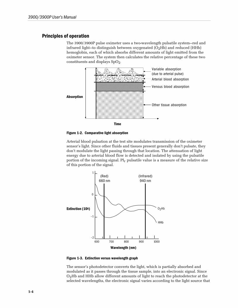
Principles of operationThe 3900/3900P pulse oximeter uses a two-wavelength pulsatile system—red andinfrared light—to distinguish between oxygenated (O2Hb) and reduced (HHb)hemoglobin, each of which absorbs different amounts of light emitted from theoximeter sensor. The system then calculates the relative percentage of these twoconstituents and displays SpO2.
Absorption
Time
Figure 1-2. Comparative light absorption
Arterial blood pulsation at the test site modulates transmission of the oximetersensor’s light. Since other fluids and tissues present generally don’t pulsate, theydon’t modulate the light passing through that location. The attenuation of lightenergy due to arterial blood flow is detected and isolated by using the pulsatileportion of the incoming signal. PIr pulsatile value is a measure of the relative sizeof this portion of the signal.
Extinction (10x)
Wavelength (nm)
Figure 1-3. Extinction versus wavelength graph
The sensor’s photodetector converts the light, which is partially absorbed andmodulated as it passes through the tissue sample, into an electronic signal. SinceO2Hb and HHb allow different amounts of light to reach the photodetector at theselected wavelengths, the electronic signal varies according to the light source that
Variable absorption(due to arterial pulse)Arterial blood absorption
Venous blood absorption
Other tissue absorption
(Red)660 nm
(Infrared)940 nm
1/Overview
1-5
is “on” and the oxygenation of the arterial hemoglobin. Analog and digital signalprocessing then converts the light-intensity information into SpO2, pulse rate, andPIr pulsatile values for display on the monitor.
CalibrationA CO-oximeter typically uses four or more wavelengths of light and calculatesreduced hemoglobin (HHb), oxyhemoglobin (O2Hb), carboxyhemoglobin (COHb),and methemoglobin (MetHb). Datex-Ohmeda pulse oximeters use twowavelengths ranges, 650 nm - 670 nm and 930 nm - 950 nm, both with an averagepower of less than 1 mW. These wavelengths are used to calculate the presence ofO2Hb and reduced HHb. Because of this, pulse oximetry readings will bedifferent than CO-oximetry readings in situations where a patient’s COHb orMetHb are increased.
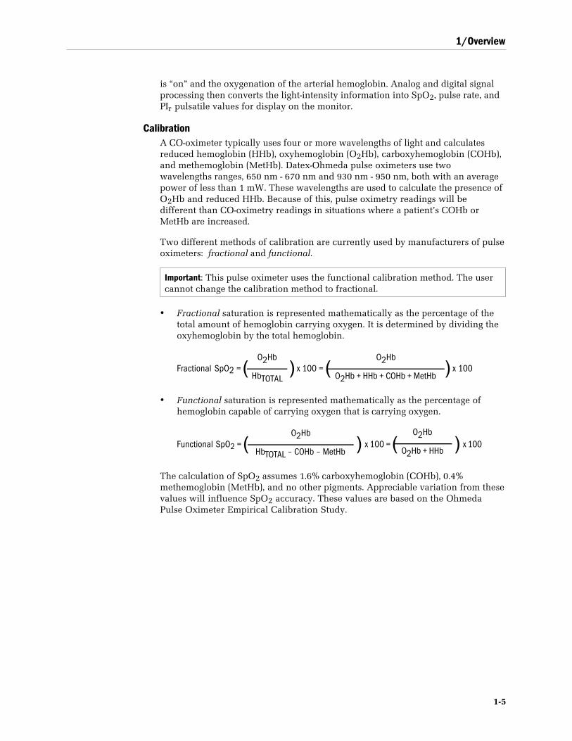
Two different methods of calibration are currently used by manufacturers of pulseoximeters: fractional and functional.
Important: This pulse oximeter uses the functional calibration method. The usercannot change the calibration method to fractional.
• Fractional saturation is represented mathematically as the percentage of thetotal amount of hemoglobin carrying oxygen. It is determined by dividing theoxyhemoglobin by the total hemoglobin.
Fractional SpO2 = ( ) x 100 = ( ) x 100
• Functional saturation is represented mathematically as the percentage ofhemoglobin capable of carrying oxygen that is carrying oxygen.
Functional SpO2 = ( ) x 100 = ( ) x 100
The calculation of SpO2 assumes 1.6% carboxyhemoglobin (COHb), 0.4%methemoglobin (MetHb), and no other pigments. Appreciable variation from thesevalues will influence SpO2 accuracy. These values are based on the OhmedaPulse Oximeter Empirical Calibration Study.
O2Hb
HbTOTAL
O2Hb
O2Hb + HHb + COHb + MetHb
O2Hb
O2Hb + HHb
O2Hb
HbTOTAL – COHb – MetHb
3900/3900P User’s Manual
1-6
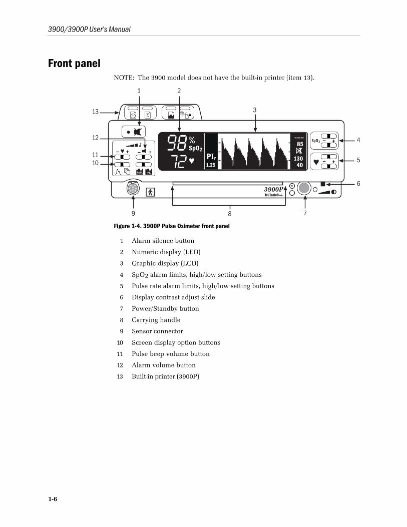
Front panelNOTE: The 3900 model does not have the built-in printer (item 13).
Figure 1-4. 3900P Pulse Oximeter front panel
1 Alarm silence button
2 Numeric display (LED)
3 Graphic display (LCD)
4 SpO2 alarm limits, high/low setting buttons
5 Pulse rate alarm limits, high/low setting buttons
6 Display contrast adjust slide
7 Power/Standby button
8 Carrying handle
9 Sensor connector
10 Screen display option buttons
11 Pulse beep volume button
12 Alarm volume button
13 Built-in printer (3900P)
1/Overview
1-7
1 Alarm silence buttonThis button has two functions:• 120-second alarm silence—activated by a single press.• Continuous all mute—activated by three quick presses (if the all-mute
feature is enabled). Press once to deactivate.
Alarm silenceWhen an active alarm condition exists, press this button to silence the audibleportion of the alarm for 120 seconds. The flashing red or yellow alarm lightbecomes a steady light. If an alarm condition still exists after 120 seconds, theaudible tone and flashing light resume.
Exceptions: Both NO SENSOR and SENSOR OFF audible alarms will not beactivated until after the unit obtains a valid signal. The same conditions applyto an active audible alarm for NO SENSOR, SENSOR OFF, or SENSORFAILURE that has been silenced; i.e., once the sensor alarm condition isacknowledged by silencing the audible alarm, a new audible alarm will notsound until the condition has been cleared and the unit obtains a valid signal.
NOTE: Pressing the alarm silence button produces 120 seconds of silence,regardless of other alarm conditions that may occur during this 120-secondinterval, except for the SYSTEM FAILURE, CONNECT UNIT TO LINEPOWER, and BUTTON STUCK alarms.
All mute
To continuously silence any alarm that can be silenced, press the alarmsilence button three times within three seconds. After you have activated allmute, the all mute icon flashes between the SpO2 and pulse rate alarm limitsettings on the right side of the screen display. (On Japanese menu screens,the icon flashes at the upper right beside the first menu option.) When analarm condition occurs, the alarm button light flashes and the alarm messageappears on the waveform display but no audible alarm sounds.
When all mute is active, press the alarm silence button once to deactivate thisfeature and enable all audible alarms.
The ability to mute all alarms continuously can be disabled; see SETTINGS,ALL MUTE in chapter 2.
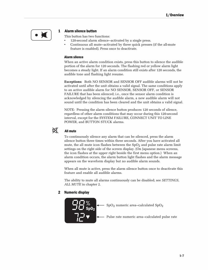
2 Numeric display
SpO2 numeric area—calculated SpO2
Pulse rate numeric area—calculated pulse rate
3900/3900P User’s Manual
1-8
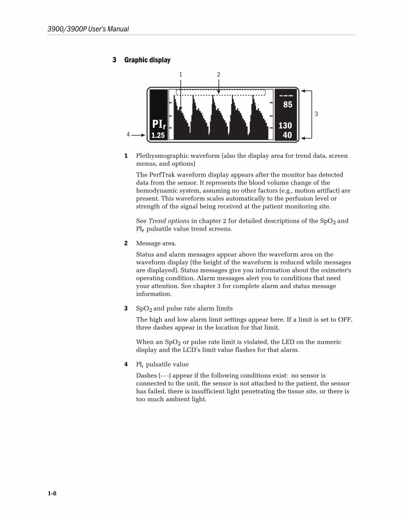
3 Graphic display
4
3
21
85
13040
PIr1.25
1 Plethysmographic waveform (also the display area for trend data, screenmenus, and options)
The PerfTrak waveform display appears after the monitor has detecteddata from the sensor. It represents the blood volume change of thehemodynamic system, assuming no other factors (e.g., motion artifact) arepresent. This waveform scales automatically to the perfusion level orstrength of the signal being received at the patient monitoring site.
See Trend options in chapter 2 for detailed descriptions of the SpO2 andPIr pulsatile value trend screens.
2 Message area.
Status and alarm messages appear above the waveform area on thewaveform display (the height of the waveform is reduced while messagesare displayed). Status messages give you information about the oximeter'soperating condition. Alarm messages alert you to conditions that needyour attention. See chapter 3 for complete alarm and status messageinformation.
3 SpO2 and pulse rate alarm limits
The high and low alarm limit settings appear here. If a limit is set to OFF,three dashes appear in the location for that limit.
When an SpO2 or pulse rate limit is violated, the LED on the numericdisplay and the LCD’s limit value flashes for that alarm.
4 PIr pulsatile value
Dashes (- - -) appear if the following conditions exist: no sensor isconnected to the unit, the sensor is not attached to the patient, the sensorhas failed, there is insufficient light penetrating the tissue site, or there istoo much ambient light.
1/Overview
1-9
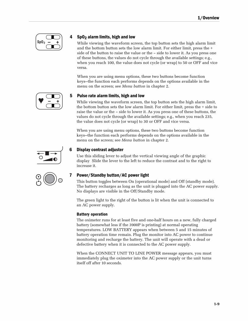
+–SpO2
4 SpO2 alarm limits, high and lowWhile viewing the waveform screen, the top button sets the high alarm limitand the bottom button sets the low alarm limit. For either limit, press the +side of the button to raise the value or the – side to lower it. As you press oneof these buttons, the values do not cycle through the available settings; e.g.,when you reach 100, the value does not cycle (or wrap) to 50 or OFF and viceversa.
When you are using menu options, these two buttons become functionkeys—the function each performs depends on the options available in themenu on the screen; see Menu button in chapter 2.
+–5 Pulse rate alarm limits, high and low
While viewing the waveform screen, the top button sets the high alarm limit,the bottom button sets the low alarm limit. For either limit, press the + side toraise the value or the – side to lower it. As you press one of these buttons, thevalues do not cycle through the available settings; e.g., when you reach 235,the value does not cycle (or wrap) to 30 or OFF and vice versa.
When you are using menu options, these two buttons become functionkeys—the function each performs depends on the options available in themenu on the screen; see Menu button in chapter 2.
6 Display contrast adjusterUse this sliding lever to adjust the vertical viewing angle of the graphicdisplay Slide the lever to the left to reduce the contrast and to the right toincrease it.
7 Power/Standby button/AC power lightThis button toggles between On (operational mode) and Off (standby mode).The battery recharges as long as the unit is plugged into the AC power supply.No displays are visible in the Off/Standby mode.
The green light to the right of the button is lit when the unit is connected toan AC power supply.
Battery operationThe oximeter runs for at least five and one-half hours on a new, fully chargedbattery (somewhat less if the 3900P is printing) at normal operatingtemperatures. LOW BATTERY appears when between 5 and 15 minutes ofbattery operation time remain. Plug the monitor into AC power to continuemonitoring and recharge the battery. The unit will operate with a dead ordefective battery when it is connected to the AC power supply.
When the CONNECT UNIT TO LINE POWER message appears, you mustimmediately plug the oximeter into the AC power supply or the unit turnsitself off after 10 seconds.
3900/3900P User’s Manual
1-10
85
13040
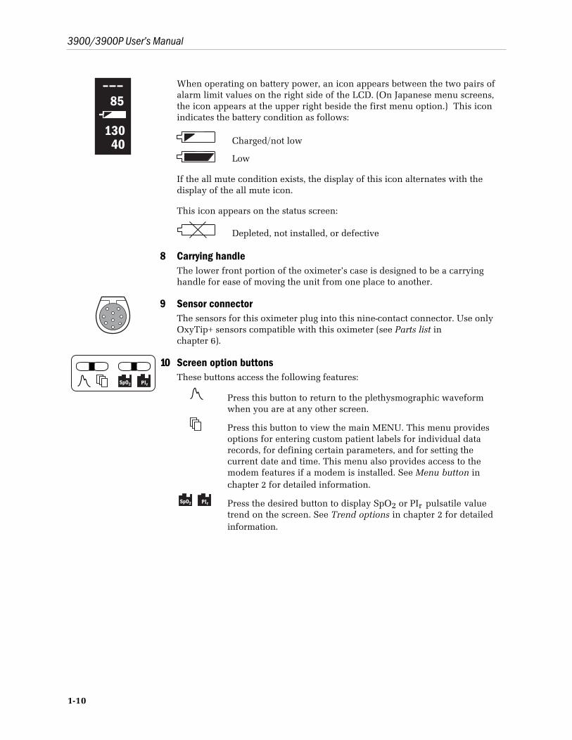
When operating on battery power, an icon appears between the two pairs ofalarm limit values on the right side of the LCD. (On Japanese menu screens,the icon appears at the upper right beside the first menu option.) This iconindicates the battery condition as follows:
Charged/not low
Low
If the all mute condition exists, the display of this icon alternates with thedisplay of the all mute icon.
This icon appears on the status screen:
Depleted, not installed, or defective
8 Carrying handleThe lower front portion of the oximeter’s case is designed to be a carryinghandle for ease of moving the unit from one place to another.
9 Sensor connectorThe sensors for this oximeter plug into this nine-contact connector. Use onlyOxyTip+ sensors compatible with this oximeter (see Parts list inchapter 6).
SpO2 PIr
10 Screen option buttonsThese buttons access the following features:
Press this button to return to the plethysmographic waveformwhen you are at any other screen.
Press this button to view the main MENU. This menu providesoptions for entering custom patient labels for individual datarecords, for defining certain parameters, and for setting thecurrent date and time. This menu also provides access to themodem features if a modem is installed. See Menu button inchapter 2 for detailed information.
SpO2 PIr Press the desired button to display SpO2 or PIr pulsatile valuetrend on the screen. See Trend options in chapter 2 for detailedinformation.
1/Overview
1-11
– + 11 Pulse beep volume buttonThis button adjusts the volume level for the pulse indicator in incrementalsteps from OFF to level 5. The power-on default is 2 if SAVE LIMITS is set toNO (see SETTINGS in chapter 2).
Press the + side of the button to increase the volume or the – side to decreaseit; you will hear the volume level as you press the button. As you press one ofthese buttons, the values do not cycle through the available settings; e.g., whenyou reach 5, the value does not cycle (or wrap) to OFF and vice versa.
As you adjust the volume, the volume setting is shown in the message areaabove the waveform.
NOTE: The pitch of the pulse tone changes as the SpO2 value increases ordecreases—the higher the SpO2 value, the higher the pitch of the pulse tone.
+– 12 Alarm volume buttonThis button adjusts the audible alarm volume level in incremental steps from1 to 5. You cannot set the alarm volume to OFF. The power-on default is 3 ifSAVE LIMITS is set to NO (see SETTINGS in chapter 2).
Press the + side of the button to increase the alarm volume or the – side todecrease it; you will hear the volume level as you press the button. As youpress one of these buttons, the values do not cycle through the availablesettings; e.g., when you reach 5, the value does not cycle (or wrap) to 1 andvice versa.
As you adjust the volume, the volume setting is shown in the message areaabove the waveform.
13 PrinterMonitoring data, current or trend, SpO2 or PIr pulsatile value, can be printedon the 3900P printer. See chapter 4 for specific operating instructions.
3900/3900P User’s Manual
1-12
Rear panel
1 2 3 4 5
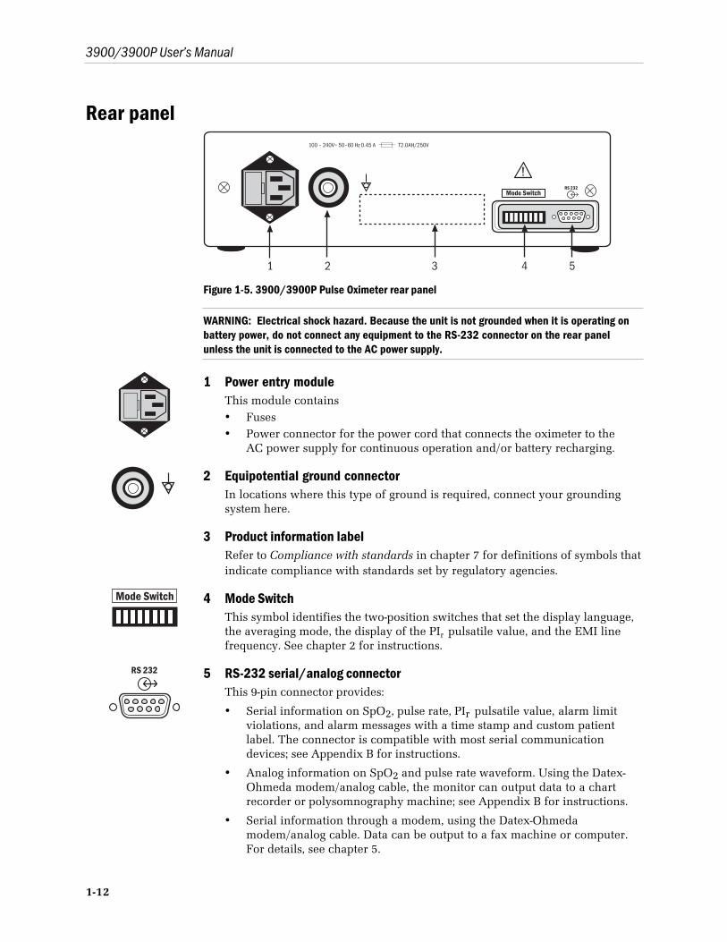
Figure 1-5. 3900/3900P Pulse Oximeter rear panel
WARNING: Electrical shock hazard. Because the unit is not grounded when it is operating onbattery power, do not connect any equipment to the RS-232 connector on the rear panelunless the unit is connected to the AC power supply.
1 Power entry moduleThis module contains• Fuses• Power connector for the power cord that connects the oximeter to the
AC power supply for continuous operation and/or battery recharging.
2 Equipotential ground connectorIn locations where this type of ground is required, connect your groundingsystem here.
3 Product information labelRefer to Compliance with standards in chapter 7 for definitions of symbols thatindicate compliance with standards set by regulatory agencies.
Mode Switch 4 Mode SwitchThis symbol identifies the two-position switches that set the display language,the averaging mode, the display of the PIr pulsatile value, and the EMI linefrequency. See chapter 2 for instructions.
RS 232 5 RS-232 serial/analog connectorThis 9-pin connector provides:
• Serial information on SpO2, pulse rate, PIr pulsatile value, alarm limitviolations, and alarm messages with a time stamp and custom patientlabel. The connector is compatible with most serial communicationdevices; see Appendix B for instructions.
• Analog information on SpO2 and pulse rate waveform. Using the Datex-Ohmeda modem/analog cable, the monitor can output data to a chartrecorder or polysomnography machine; see Appendix B for instructions.
• Serial information through a modem, using the Datex-Ohmedamodem/analog cable. Data can be output to a fax machine or computer.For details, see chapter 5.
1/Overview
1-13
PrecautionsTwo types of precautions appear in this manual: warnings and cautions.
• A WARNING indicates the possibility of injury to the patient or operator.
• A CAUTION indicates a condition that may lead to equipment damage ormalfunction.
NOTE: If you connect a modem, refer to the precautions contained in theinstructions you received with your modem.
WarningsFailure of operation
If the oximeter fails any part of the checkout procedures or current leakage test,remove it from operation until qualified service personnel have corrected thesituation.
It is possible for any device to malfunction; therefore, always verify unusual databy performing a formal patient assessment.
Data validityConditions that may cause inaccurate readings and impact alarms includeinterfering substances, excessive ambient light, electrical interference, excessivemotion, low perfusion, low signal strength, incorrect sensor placement, poor sensorfit, and movement of the sensor on the patient.
To prevent erroneous readings, do not use an inflated blood pressure cuff orarterial blood pressure measurement device on the same limb as the oximetersensor.
Explosion hazardDo not use the monitor in the presence of any flammable anesthetic mixture.
Electrical shock hazardDo not remove the monitor cover. An operator may only perform maintenanceprocedures specifically described in this manual. Refer servicing to qualifiedservice personnel trained in the repair of this equipment.
Measure the oximeter’s leakage current whenever an external device is connectedto the RS-232 port. Forward and reverse polarity = 100 microamperes maximum.
This equipment must be properly grounded.
• Electrical safety specifications (e.g., current leakage and ground resistance)can be assured only when the monitor is connected to a three-wire, groundedreceptacle without the use of extension cords or adapters.
• If there is any doubt about the integrity of the AC power supply protectiveearth conductor, operate the monitor on internal battery power.
• Because the unit is not grounded when it is operating on battery power, do notconnect any equipment to the RS-232 connector on the rear panel unless theunit is connected to the AC power supply.

3900/3900P User’s Manual
1-14
Electrical shock and flammability hazardBefore cleaning or servicing the oximeter, always turn it off and disconnect thepower cord from the AC power supply.
Patient safetyThe correct use of the oximeter is to measure only arterial oxygen saturation(SpO2), pulse rate, and Relative Perfusion Index pulsatile value.
• A pulse oximeter does not measure respiration and should never be used as asubstitute for an apnea monitor or as the primary monitor for infants beingmonitored for apnea.
• A pulse oximeter may be used during sleep studies of adults only to gatherinformation regarding SpO2, pulse rate, and PIr pulsatile value.
This device is not intended for use in a magnetic resonance imaging (MRI)environment.
Patient safety (sensors)Patient conditions (such as reddening, blistering, skin discoloration, ischemic skinnecrosis, and skin erosion) may warrant changing the sensor site frequently orusing a different style of sensor.
To prevent patient injury or equipment damage, use only OxyTip+ oximetersensors approved for use with this oximeter. For complete information about thesafe and appropriate use of a sensor, consult the instructions for that sensor.
Discard a damaged sensor immediately. Do not repair a damaged sensor or use asensor repaired by others.
Patient safety (modem)Do not use the modem within the patient environment defined below:
1.5 m (5 ft)1.5 m (5 ft)
1.5 m
(5 ft)
2.5
m (8
.2 ft
)
Do not connect the modem to the oximeter when the oximeter is operating onbattery power.
RS-232 system interconnectionAccessory equipment connected to the RS-232 serial/analog connector must becertified according to the current version of the respective IEC/EN standards(e.g., IEC 60950 for data processing equipment and IEC/EN 60601-1 for medicalequipment). All configurations shall also comply with IEC/EN 60601-1-1. Anyonewho connects additional equipment to the RS-232 serial/analog connectorconfigures a medical system, and is therefore responsible that the system complieswith the requirements of IEC/EN 60601-1-1. If in doubt, call your local authorized
1/Overview
1-15
service office. The 3900/3900P is referred to as an IEC/EN 60601/F device in the summary of situations table contained in IEC/EN 60601-1-1.
CautionsHandle the monitor with care
Improper handling can cause damage or inaccurate results.
CleaningDo not autoclave, pressure sterilize, or gas sterilize this oximeter.
Use cleaning solution sparingly. Do not soak or immerse the monitor in liquid.Excessive solution can flow into the monitor and damage internal components.
When cleaning the display area, do not use abrasive cleaning compounds or othermaterials that could damage the screen.
Do not use petroleum-based solutions, acetone solutions, or other harsh solvents toclean the oximeter. These substances may damage the oximeter and cause amalfunction.
To prevent damage to the 3900P printer, do not allow any cleaning solution to getinto the printer mechanism.
SensorsDo not apply tension to the sensor cable; sensor damage may result.
BatteryThe 3900/3900P internal battery, containing lead and acid, is a hazardous waste.Dispose of the battery through an approved hazardous materials disposal facilityor return it to Datex-Ohmeda for disposal.
To prevent damage to the lead-acid battery, do not turn the monitor on after theLOW BATTERY message appears without first plugging it in to the AC powersupply.
PrinterTo avoid damage to the print head, do not operate the printer without paper.Paper purchased from Datex-Ohmeda has red edges when the paper roll isnearing depletion.
To avoid damage to the printer, never pull the paper backward through theprinter mechanism.
To avoid damaging the printhead mechanism, discharge any possible staticelectricity from your person before removing the paper feed cover on the printer.
DisposalDispose of this medical device and its packing materials according to localrequirements.

3900/3900P User’s Manual
1-16
2-1
2/Setup and OperationsThis chapter provides the following information and instructions:
• Powering the oximeter.
• Selecting the language, averaging mode, PIr pulsatile value display, and EMI(electromagnetic interference) line frequency.
• Checkout procedure—to determine that all functions of the 3900/3900Poximeter are working properly.
• Signal and data validity guidelines.
• Menu options.
• Trend data options; SpO2 and PIr pulsatile value.
• Lock-buttons procedure—to prevent changes to the monitor’s settings.
To operate the 3900/3900P oximeter effectively, you must
• Know how the oximeter derives its readings (see Principles of operation inchapter 1).
• Be familiar with its controls and components (see chapter 1).
• Understand its messages (see chapter 3).
Powering the oximeterThe 3900/3900P pulse oximeter is designed to operate on battery power and on allcommonly available voltage supplies. Your oximeter was shipped with the correctpower cord for your local AC power supply. Any hospital-grade power cord,however, with the female connector end that fits into the power module (IEC-320type) on the 3900/3900P can be used; the male connector that plugs into thegrounded “wall” outlet may be whatever is needed locally. The oximeter accepts arange of AC mains power; see chapter 7 for details.
To protect data validity in cases of possible electromagnetic interference, makesure the EMI line frequency mode switch is set to the same frequency as yourlocal AC power supply before using the unit for patient monitoring; see EMI linefrequency under Mode switch settings later in this chapter.
A battery does not need to be installed for the oximeter to operate on the ACpower supply.
3900/3900P User’s Manual
2-2
Setup
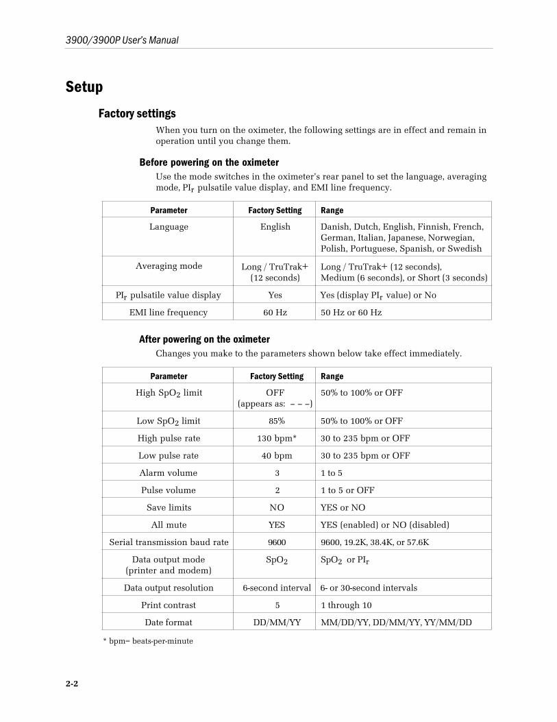
Factory settingsWhen you turn on the oximeter, the following settings are in effect and remain inoperation until you change them.
Before powering on the oximeterUse the mode switches in the oximeter’s rear panel to set the language, averagingmode, PIr pulsatile value display, and EMI line frequency.
Parameter Factory Setting Range
Language English Danish, Dutch, English, Finnish, French,German, Italian, Japanese, Norwegian,Polish, Portuguese, Spanish, or Swedish
Averaging mode Long / TruTrak+(12 seconds)
Long / TruTrak+ (12 seconds),Medium (6 seconds), or Short (3 seconds)
PIr pulsatile value display Yes Yes (display PIr value) or No
EMI line frequency 60 Hz 50 Hz or 60 Hz
After powering on the oximeterChanges you make to the parameters shown below take effect immediately.
Parameter Factory Setting Range
High SpO2 limit OFF(appears as: – – –)
50% to 100% or OFF
Low SpO2 limit 85% 50% to 100% or OFF
High pulse rate 130 bpm* 30 to 235 bpm or OFF
Low pulse rate 40 bpm 30 to 235 bpm or OFF
Alarm volume 3 1 to 5
Pulse volume 2 1 to 5 or OFF
Save limits NO YES or NO
All mute YES YES (enabled) or NO (disabled)
Serial transmission baud rate 9600 9600, 19.2K, 38.4K, or 57.6K
Data output mode(printer and modem)
SpO2 SpO2 or PIr
Data output resolution 6-second interval 6- or 30-second intervals
Print contrast 5 1 through 10
Date format DD/MM/YY MM/DD/YY, DD/MM/YY, YY/MM/DD
* bpm= beats-per-minute
2/Setup and Operations
2-3
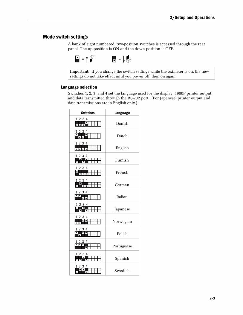
Mode switch settingsA bank of eight numbered, two-position switches is accessed through the rearpanel. The up position is ON and the down position is OFF.
=
=
Important: If you change the switch settings while the oximeter is on, the newsettings do not take effect until you power off, then on again.
Language selectionSwitches 1, 2, 3, and 4 set the language used for the display, 3900P printer output,and data transmitted through the RS-232 port. (For Japanese, printer output anddata transmissions are in English only.)
Switches Language
1 2 3 4Danish
1 2 3 4Dutch
1 2 3 4English
1 2 3 4Finnish
1 2 3 4French
1 2 3 4German
1 2 3 4Italian
1 2 3 4Japanese
1 2 3 4Norwegian
1 2 3 4Polish
1 2 3 4Portuguese
1 2 3 4Spanish
1 2 3 4Swedish
3900/3900P User’s Manual
2-4
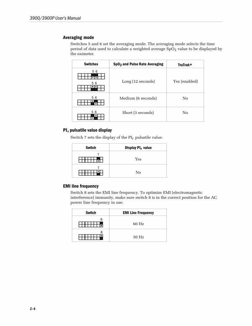
Averaging modeSwitches 5 and 6 set the averaging mode. The averaging mode selects the timeperiod of data used to calculate a weighted average SpO2 value to be displayed bythe oximeter.
Switches SpO2 and Pulse Rate Averaging TruTrak+5 6
5 6 Long (12 seconds) Yes (enabled)
5 6 Medium (6 seconds) No
5 6 Short (3 seconds) No
PIr pulsatile value displaySwitch 7 sets the display of the PIr pulsatile value.
Switch Display PIr value
7Yes
7No
EMI line frequencySwitch 8 sets the EMI line frequency. To optimize EMI (electromagneticinterference) immunity, make sure switch 8 is in the correct position for the ACpower line frequency in use.
Switch EMI Line Frequency
860 Hz
850 Hz
2/Setup and Operations
2-5
Checkout procedureWARNING: Failure of operation. If the oximeter fails any part of the checkout procedures orcurrent leakage tests, remove it from operation until qualified service personnel havecorrected the situation.
WARNING: Explosion hazard. Do not use the monitor in the presence of any flammableanesthetic mixture.
WARNING: Electrical shock hazard. This equipment must be properly grounded.
• Electrical safety specifications (e.g., current leakage and ground resistance) can beassured only when the monitor is connected to a three-wire, grounded receptacle withoutthe use of extension cords or adapters.
• If there is any doubt about the integrity of the AC power supply protective earth conductor,operate the monitor on internal battery power.
• Because the unit is not grounded when it is operating on battery power, do not connectany equipment to the RS-232 connector on the rear panel unless the unit is connected tothe AC power supply.
If you plan to send serial or analog data to another device, make sure the device isconnected to the rear panel connector before you power on the monitor andmake sure the monitor is connected to the AC power supply.
Important: For TruTrak+ performance, the averaging mode must be set to Long.
1. Inspect the oximeter case for damage. Make sure the display windows areclean.
WARNING: Sensors
• Discard a damaged sensor immediately. Do not repair a damaged sensor or use asensor repaired by others.
• To prevent patient injury or equipment damage, use only Datex-Ohmeda oximetersensors approved for use with this oximeter. For complete information about the safeand appropriate use of a sensor, consult the instructions for that sensor.
CAUTION: Do not apply tension to the sensor cable; sensor damage may result.
2. Check that the sensor is a compatible model before connecting it to theoximeter. Only Datex-Ohmeda OxyTip+ sensors can be used with this monitor.
If you’re using a reusable sensor, make sure it opens and closes smoothly.Remove substances that may interfere with the transmission of light betweenthe sensor's light source and detector.
3. Connect the sensor cable to the sensor connector on the monitor. Make surethe connection is firm and that the cable is not twisted, sliced, or frayed.
4. Attach the sensor to a finger or an ear, depending on the sensor you are using.

3900/3900P User’s Manual
2-6
5. To turn on the oximeter, press the power button.
The first screen shows the Datex-Ohmeda logo and the model name(Model 3900 or Model 3900P).
Important: If the low SpO2 alarm limit was saved at a limit lower than 80%(or at OFF), you will be alerted by a screen message that shows the currentlow SpO2 alarm limit and alarm volume level:
LIMITS SAVED
LOW SpO2 = 75%
The next screen shows the averaging mode in effect, the SpO2 calibrationmode, the progress of the self-test, and the status of the battery charge.
Averaging Mode: Long
SpO2 Calibration: Functional
Self-test in progress …
(indicates battery-charge status)
Below the bar graph, the version number of the unit’s system and oximetrysoftware appears as Version X.XXX/YY.YYY, where X’s represent the systemsoftware version and Y’s the oximetry software version.
Diagnostic self-testDuring this time the system performs a diagnostic self-test (electronics,battery status, analog signal path integrity, calibration check) and sets thedefault parameters. This self-test takes approximately 10 seconds.
• A start-up tone sequence tests the audio circuit; all display LEDs andthe LCD backlight are illuminated, then blanked.
• The alarm LED toggles between red and yellow while a numericcountdown from 9 to 0 occurs on each seven-segment LED displayending with a decimal point.
• A battery icon is displayed to indicate the battery condition as eithercharged, depleted, or defective/missing (see chapter 3).
Upon successful completion of all diagnostic self-tests, the unit isconsidered to be in calibration and begins normal operation. This messageis displayed:
Test passed. In calibration.
If the unit does not pass the self-test, an error message is displayed and theunit is inoperable.
2/Setup and Operations
2-7
6. On the displays, verify
• The high and low alarm limits for SpO2 and pulse rate.
• Dashes (– – –) appear for any limit set to OFF.
• The readings for SpO2, pulse rate, and PIr pulsatile value.
Dashes may appear on the display until the SpO2, pulse rate, and PIrpulsatile value readings have stabilized (approximately 12 seconds).
NOTE: The audible alarm feature for all alarm conditions is silenced for the firsttwo minutes after powering on.
7. If two minutes have elapsed since you powered on, verify that the patientalarms are functional by setting the high and low SpO2 and pulse rate alarmlimits beyond the current readings. Make sure
• An alarm tone sounds.
• The violated alarm limit and reading flash on the display.
• Depending on the priority of the alarm, a red or yellow alarm light flashes.
8. Verify the sensor alarms are functional by removing the sensor from thesensor site. Make sure
• SENSOR OFF or CHECK SENSOR SITE appears in the message area ofthe graphic display.
• The alarm tone sounds; the alarm light flashes.
9. Unplug the sensor from the oximeter. Make sure
• NO SENSOR appears.
• The alarm tone sounds; the alarm light flashes.
10. Press the alarm silence button. Make sure
• The alarm tone ceases.
• The alarm light is steady.
11. To begin patient monitoring, connect the desired Datex-Ohmeda sensor to theoximeter. Attach that sensor to the patient.
To verify the sensor is on correctly and that the data are verifiable, see Signal anddata validity in this chapter.
WARNING: Patient safety. Patient conditions (such as reddening, blistering, skin discoloration,ischemic skin necrosis, and skin erosion) may warrant changing the sensor site frequently orusing a different style of sensor.
3900/3900P User’s Manual
2-8
Signal and data validity
Plethysmographic waveformThe oximeter’s PerfTrak waveform display provides a visual indicator of thevalidity of the values that appear on the display. The waveform is scaled tocorrespond to the perfusion level or strength of the signal being received at thepatient monitoring site.
NOTE: When a message appears in the upper portion of the LCD, the waveformrectangle becomes smaller but the correspondence between signal strength andwaveform height is maintained.
You should be able to easily identify three complete passes of theplethysmographic waveform. Although the waveform shape may vary from patientto patient, under normal conditions it corresponds to the arterial pressurewaveform.
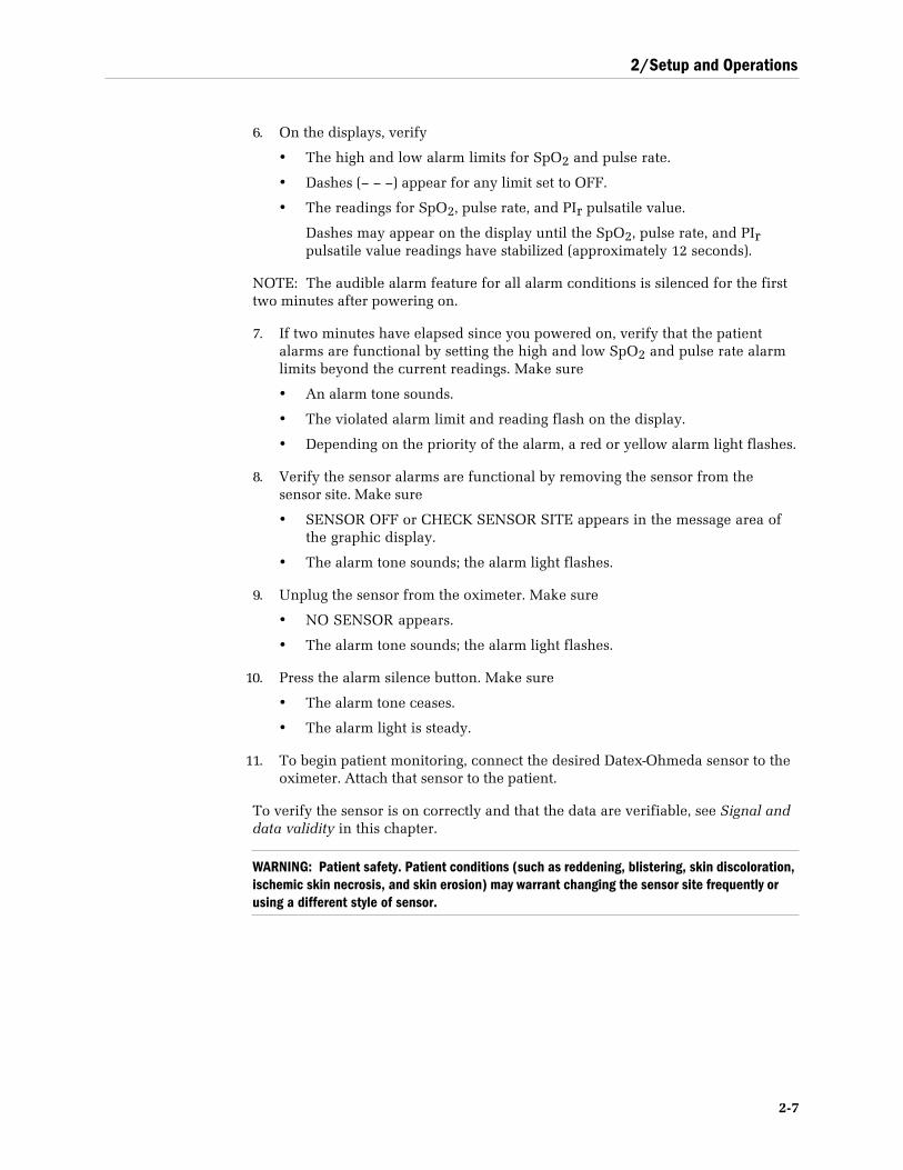
Use Figures 2-1 (adult) and 2-2 (neonate) as guidelines to determine a sensorplacement that generates the fewest noise spikes.
Figure 2-1. Typical adult plethysmographic waveform
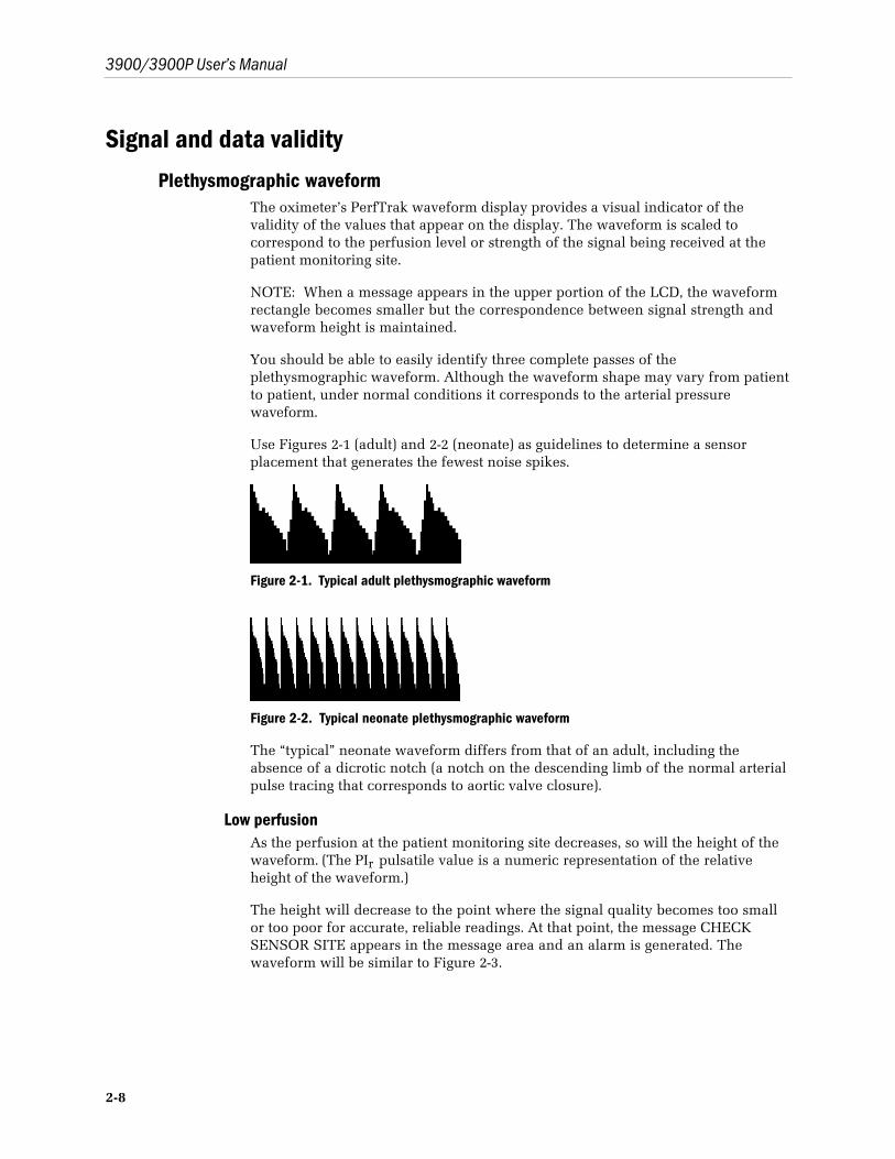
Figure 2-2. Typical neonate plethysmographic waveform
The “typical” neonate waveform differs from that of an adult, including theabsence of a dicrotic notch (a notch on the descending limb of the normal arterialpulse tracing that corresponds to aortic valve closure).
Low perfusionAs the perfusion at the patient monitoring site decreases, so will the height of thewaveform. (The PIr pulsatile value is a numeric representation of the relativeheight of the waveform.)
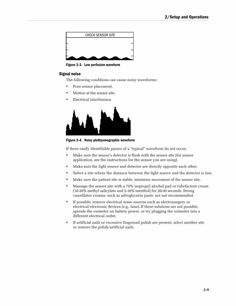
The height will decrease to the point where the signal quality becomes too smallor too poor for accurate, reliable readings. At that point, the message CHECKSENSOR SITE appears in the message area and an alarm is generated. Thewaveform will be similar to Figure 2-3.
2/Setup and Operations
2-9
Figure 2-3. Low perfusion waveform
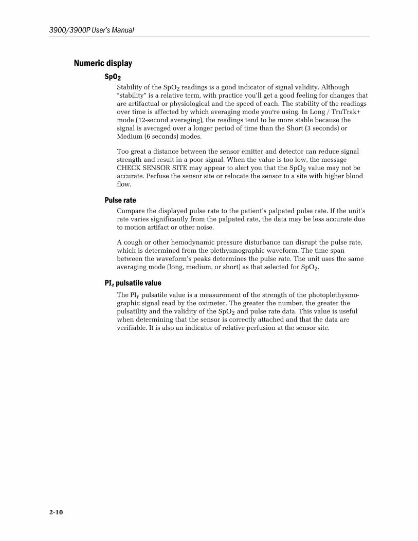
Signal noiseThe following conditions can cause noisy waveforms:
• Poor sensor placement.
• Motion at the sensor site.
• Electrical interference.
Figure 2-4. Noisy plethysmographic waveform
If three easily identifiable passes of a “typical” waveform do not occur,
• Make sure the sensor’s detector is flush with the sensor site (for sensorapplication, see the instructions for the sensor you are using).
• Make sure the light source and detector are directly opposite each other.
• Select a site where the distance between the light source and the detector is less.
• Make sure the patient site is stable; minimize movement of the sensor site.
• Massage the sensor site with a 70% isopropyl alcohol pad or rubefacient cream(10-30% methyl salicylate and 2-10% menthol) for 20-30 seconds. Strongvasodilator creams, such as nitroglycerin paste, are not recommended.
• If possible, remove electrical noise sources such as electrosurgery orelectrical/electronic devices (e.g., fans). If these solutions are not possible,operate the oximeter on battery power, or try plugging the oximeter into adifferent electrical outlet.
• If artificial nails or excessive fingernail polish are present, select another siteor remove the polish/artificial nails.
CHECK SENSOR SITE
3900/3900P User’s Manual
2-10
Numeric displaySpO2
Stability of the SpO2 readings is a good indicator of signal validity. Although“stability” is a relative term, with practice you’ll get a good feeling for changes thatare artifactual or physiological and the speed of each. The stability of the readingsover time is affected by which averaging mode you're using. In Long / TruTrak+mode (12-second averaging), the readings tend to be more stable because thesignal is averaged over a longer period of time than the Short (3 seconds) orMedium (6 seconds) modes.
Too great a distance between the sensor emitter and detector can reduce signalstrength and result in a poor signal. When the value is too low, the messageCHECK SENSOR SITE may appear to alert you that the SpO2 value may not beaccurate. Perfuse the sensor site or relocate the sensor to a site with higher bloodflow.
Pulse rateCompare the displayed pulse rate to the patient’s palpated pulse rate. If the unit’srate varies significantly from the palpated rate, the data may be less accurate dueto motion artifact or other noise.
A cough or other hemodynamic pressure disturbance can disrupt the pulse rate,which is determined from the plethysmographic waveform. The time spanbetween the waveform’s peaks determines the pulse rate. The unit uses the sameaveraging mode (long, medium, or short) as that selected for SpO2.
PIr pulsatile valueThe PIr pulsatile value is a measurement of the strength of the photoplethysmo-graphic signal read by the oximeter. The greater the number, the greater thepulsatility and the validity of the SpO2 and pulse rate data. This value is usefulwhen determining that the sensor is correctly attached and that the data areverifiable. It is also an indicator of relative perfusion at the sensor site.
2/Setup and Operations
2-11
Waveform screen buttonWhen you are viewing some other display or screen, press this button to return tothe waveform screen. You can also use this button to exit from a menu or optionscreen to prevent changes you have made from being confirmed.
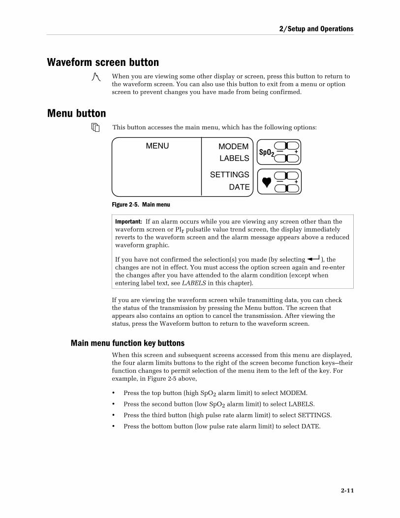
Menu buttonThis button accesses the main menu, which has the following options:
MENU
DATE
MODEM
LABELS
SETTINGS
— +SpO2
— +
Figure 2-5. Main menu
Important: If an alarm occurs while you are viewing any screen other than thewaveform screen or PIr pulsatile value trend screen, the display immediatelyreverts to the waveform screen and the alarm message appears above a reducedwaveform graphic.
If you have not confirmed the selection(s) you made (by selecting ), thechanges are not in effect. You must access the option screen again and re-enterthe changes after you have attended to the alarm condition (except whenentering label text, see LABELS in this chapter).
If you are viewing the waveform screen while transmitting data, you can checkthe status of the transmission by pressing the Menu button. The screen thatappears also contains an option to cancel the transmission. After viewing thestatus, press the Waveform button to return to the waveform screen.
Main menu function key buttonsWhen this screen and subsequent screens accessed from this menu are displayed,the four alarm limits buttons to the right of the screen become function keys—theirfunction changes to permit selection of the menu item to the left of the key. Forexample, in Figure 2-5 above,
• Press the top button (high SpO2 alarm limit) to select MODEM.
• Press the second button (low SpO2 alarm limit) to select LABELS.
• Press the third button (high pulse rate alarm limit) to select SETTINGS.
• Press the bottom button (low pulse rate alarm limit) to select DATE.
3900/3900P User’s Manual
2-12
LABELSThis main menu option accesses the screen where you can enter custom patientlabels—alphanumeric characters that help identify patients and their associateddata. There are four lines available to enter labels.
A label is included in data transmissions and printouts. If you use the modem orfax function, we recommend that you enter a label to identify the patient. If youdo not enter a label, the report will contain four blank lines, on which you canwrite the patient’s name. If you do not want a label, clear all text from the LABELSscreen.
If a custom patient label is desired, the label text mmmmuuuusssstttt be entered beforemonitoring begins. Once the label is entered into memory, aaaallllllll subsequent patientdata stored to memory is associated with that label (unless it is cleared orchanged). If a new label is not entered prior to monitoring, the data will beassociated with the previous label.
Once the label is input on the LABELS screen, you must press to store thelabel to trend memory. If you fail to press , the label is simply present on theLABELS screen and is not stored in trend memory.
Labels are stored in memory along with their associated SpO2 and PIr pulsatilevalue data. A new record is created in memory each time a new label is stored tomemory, the oximeter is turned off, or the date and/or time are changed. When areport is generated, a page break and new headings print for each new record.
The labels you create remain in trend memory until you clear the trend data oruntil all the patient data associated with the label are overwritten; i.e., when 24hours of data are already stored in memory and the oldest records are overwrittenas additional data are recorded and stored to memory.
If labels and associated data are cleared from trend memory but label text is notcleared from the LABELS screen when you begin monitoring again, any text onthe LABELS screen is used to identify the new record.
Summary: custom patient labels• Labels are used to identify patients.
• Labels are included in all printed reports (3900P) and data transmissions.
• Labels must be entered prior to monitoring patients.
• Labels create new records in trend memory.
• Labels are cleared from the LABELS screen and/or from trend memory byusing the CLEAR button on the LABELS screen (Figure 2-6) and the trendscreens (Figure 2-9).
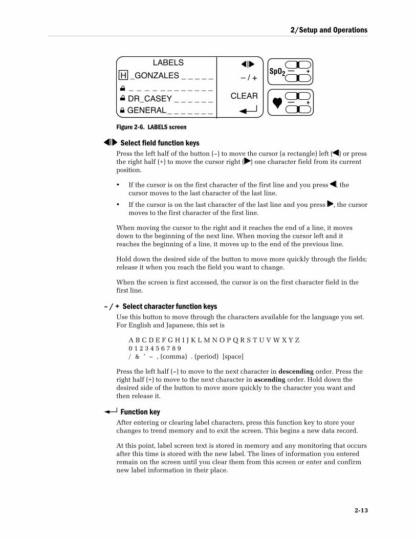
2/Setup and Operations
2-13
LABELS
H _GONZALES _ _ _ _ _ _ _ _ _ _ _ _ _ _ _ _ _DR_CASEY _ _ _ _ _ _GENERAL _ _ _ _ _ _ _
– / +
CLEARO
O
O
— +SpO2
— +
Figure 2-6. LABELS screen
Select field function keysPress the left half of the button (–) to move the cursor (a rectangle) left ( ) or pressthe right half (+) to move the cursor right ( ) one character field from its currentposition.
• If the cursor is on the first character of the first line and you press , thecursor moves to the last character of the last line.
• If the cursor is on the last character of the last line and you press , the cursormoves to the first character of the first line.
When moving the cursor to the right and it reaches the end of a line, it movesdown to the beginning of the next line. When moving the cursor left and itreaches the beginning of a line, it moves up to the end of the previous line.
Hold down the desired side of the button to move more quickly through the fields;release it when you reach the field you want to change.
When the screen is first accessed, the cursor is on the first character field in thefirst line.
– / + Select character function keysUse this button to move through the characters available for the language you set.For English and Japanese, this set is
A B C D E F G H I J K L M N O P Q R S T U V W X Y Z0 1 2 3 4 5 6 7 8 9/ & ’ – , (comma) . (period) [space]
Press the left half (–) to move to the next character in descending order. Press theright half (+) to move to the next character in ascending order. Hold down thedesired side of the button to move more quickly to the character you want andthen release it.
Function keyAfter entering or clearing label characters, press this function key to store yourchanges to trend memory and to exit the screen. This begins a new data record.
At this point, label screen text is stored in memory and any monitoring that occursafter this time is stored with the new label. The lines of information you enteredremain on the screen until you clear them from this screen or enter and confirmnew label information in their place.
3900/3900P User’s Manual
2-14
NOTE: If an alarm occurs while you are entering label characters, the waveformscreen appears with the alarm message. After you have attended to the alarmcondition, return to the LABELS screen. The characters you had entered prior tothe alarm are still there but they are not yet saved in memory as the label for thecurrent data record. You do not have to reenter them, but you do need tocomplete the label information and then press to save the label to memory.
CLEARSelect CLEAR to access the clear patient data screen options:
Option Action
CLEAR LABELS Clears label text from unlocked lines on the LABELSscreen.
CLEAR TREND Clears all SpO2 and PIr trend data in memory, includingthe labels in memory associated with that data.
CLEAR BOTH Clears label text from unlocked lines on the LABELSscreen and clears all stored trend data, including labelsin memory associated with that data.
After choosing an option, you can confirm your choice by selecting YES or NO.
• If you select YES, a high beep tone sounds. If you select NO, a low beep tonesounds. A message indicating that the labels, trends, or both have or have notbeen cleared (depending on your selection) is displayed for three seconds.
• If you do not select YES or NO within 10 seconds, a low beep tone sounds andthe previous screen is displayed.
NOTE: Text on the LABELS screen that is not erased will be used for the nextdata record.
Locking label linesLine 1 remains in memory until you change it (or clear it) and press . Thisline has 13 character fields and it cannot be locked.
Lines 2, 3, and 4 can each be locked to retain their information until you unlockthe lines and change the text or use CLEAR to remove it. These lines have 12character fields each. The first character field on each line is reserved for a lock orunlock symbol. With the cursor on the symbol, use the –/+ function keys to switchbetween the symbols and thereby lock or unlock that line. When a line is locked,it is not erased from the screen when you select CLEAR.
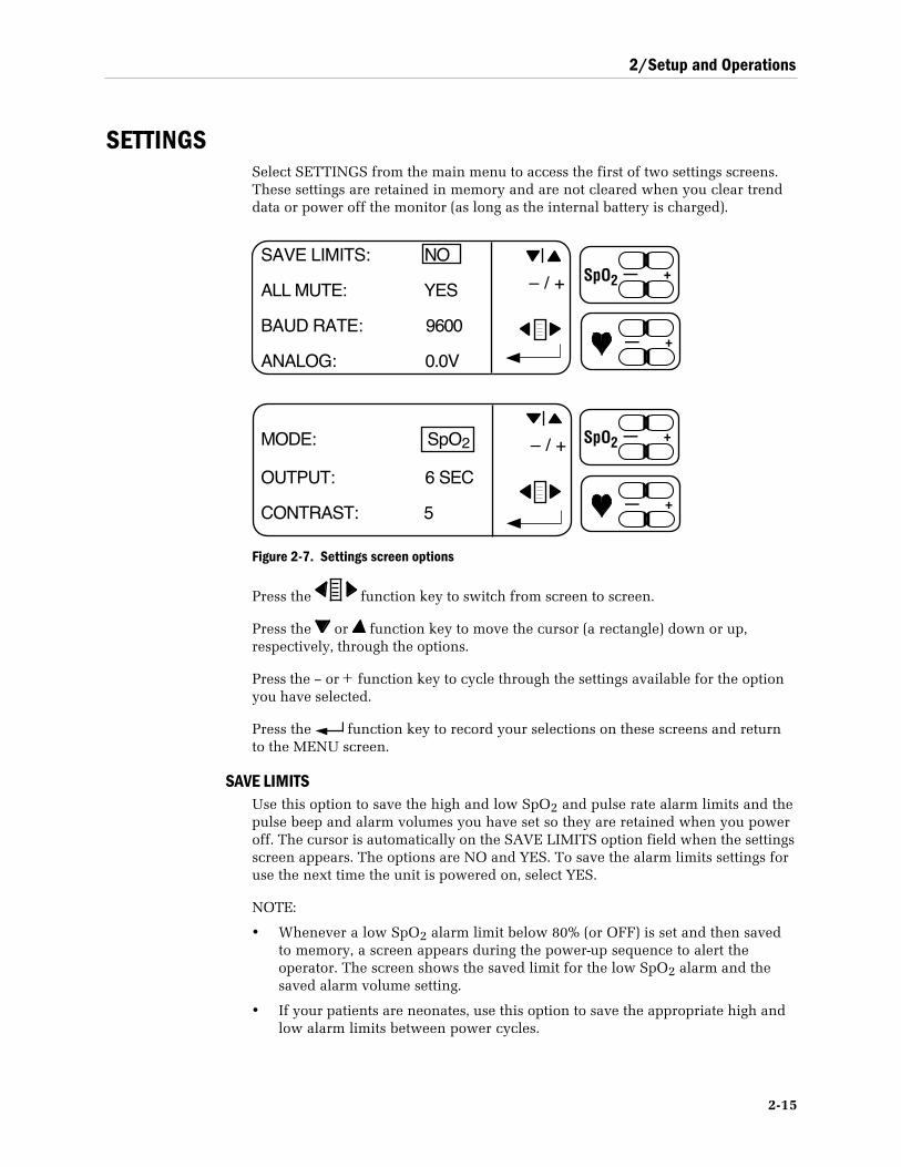
2/Setup and Operations
2-15
SETTINGSSelect SETTINGS from the main menu to access the first of two settings screens.These settings are retained in memory and are not cleared when you clear trenddata or power off the monitor (as long as the internal battery is charged).
— +SpO2
— +
– / +
SAVE LIMITS: NO
ALL MUTE: YES
BAUD RATE: 9600
ANALOG: 0.0V
– / +MODE: SpO2
OUTPUT: 6 SEC
CONTRAST: 5
— +SpO2
— +
Figure 2-7. Settings screen options
Press the function key to switch from screen to screen.
Press the or function key to move the cursor (a rectangle) down or up,respectively, through the options.
Press the – or + function key to cycle through the settings available for the optionyou have selected.
Press the function key to record your selections on these screens and returnto the MENU screen.
SAVE LIMITSUse this option to save the high and low SpO2 and pulse rate alarm limits and thepulse beep and alarm volumes you have set so they are retained when you poweroff. The cursor is automatically on the SAVE LIMITS option field when the settingsscreen appears. The options are NO and YES. To save the alarm limits settings foruse the next time the unit is powered on, select YES.
NOTE:
• Whenever a low SpO2 alarm limit below 80% (or OFF) is set and then savedto memory, a screen appears during the power-up sequence to alert theoperator. The screen shows the saved limit for the low SpO2 alarm and thesaved alarm volume setting.
• If your patients are neonates, use this option to save the appropriate high andlow alarm limits between power cycles.
3900/3900P User’s Manual
2-16
ALL MUTEUse this option to enable (YES) or disable (NO) the ability to mute audible alarms.
• When enabled (YES), you can press the alarm silence button three times(within 3 seconds) and silence the alarms until you press the alarm silencebutton again (or the unit is powered off).
• When disabled (NO), you cannot silence the alarms continuously.
BAUD RATEUse this option to select the appropriate baud rate when sending serial datadirectly to a computer; see Appendix B for more information. The options are9600, 19.2K, 38.4K, and 57.6K.
ANALOGUse this option to calibrate an analog device (chart recorder, polysomnographymachine, etc.). The options are 0.0V, 0.5V, and 1.0V. See Appendix B for moredetailed information.
MODEUse this option to select between SpO2 or PIr pulsatile value modes. The modeyou select determines the data and format used for printer and modem output.The mode also determines whether an alarm condition will cause a trend displayscreen to revert to the waveform screen.
OUTPUTUse this option to select 6-second or 30-second interval formats when printing data.
6 sec (second) output specifies the following:Trend data: every data point for SpO2 or PIr data.Current data: lowest data point for SpO2 and the average PIr value for that6 seconds.
30 sec (second) output specifies the following for trend data:SpO2: the lowest data point out of every 5.PIr: the average of 5 data points.
CONTRAST (3900P printer only)If you have the 3900P, this option allows you to adjust the print quality of theprinter output. The options are 1, (lightest print) through 10 (darkest print). Pressthe – or + function key to decrease or increase, respectively, the print quality.
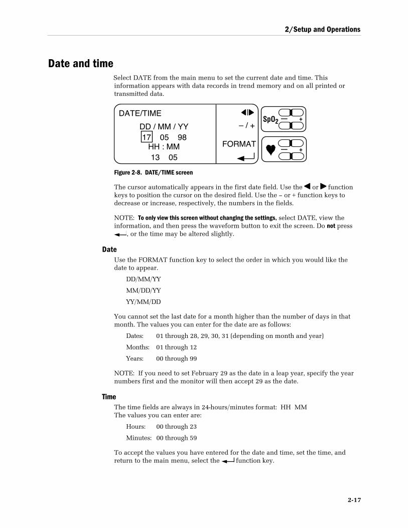
2/Setup and Operations
2-17
Date and timeSelect DATE from the main menu to set the current date and time. Thisinformation appears with data records in trend memory and on all printed ortransmitted data.
DATE/TIME
DD / MM / YY17 05 98
HH : MM13 05
FORMAT
– / +— +SpO2
— +
Figure 2-8. DATE/TIME screen
The cursor automatically appears in the first date field. Use the or functionkeys to position the cursor on the desired field. Use the – or + function keys todecrease or increase, respectively, the numbers in the fields.
NOTE: To only view this screen without changing the settings, select DATE, view theinformation, and then press the waveform button to exit the screen. Do not press
, or the time may be altered slightly.
DateUse the FORMAT function key to select the order in which you would like thedate to appear.
DD/MM/YY
MM/DD/YY
YY/MM/DD
You cannot set the last date for a month higher than the number of days in thatmonth. The values you can enter for the date are as follows:
Dates: 01 through 28, 29, 30, 31 (depending on month and year)
Months: 01 through 12
Years: 00 through 99
NOTE: If you need to set February 29 as the date in a leap year, specify the yearnumbers first and the monitor will then accept 29 as the date.
TimeThe time fields are always in 24-hours/minutes format: HH MMThe values you can enter are:
Hours: 00 through 23
Minutes: 00 through 59
To accept the values you have entered for the date and time, set the time, andreturn to the main menu, select the function key.
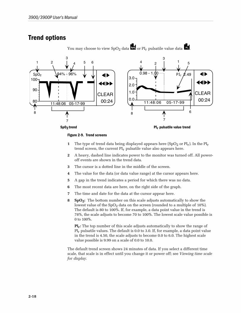
3900/3900P User’s Manual
2-18
Trend optionsYou may choose to view SpO2 data SpO2 or PIr pulsatile value data P Ir .
CLEAR00:24
SpO2 94% - 96%100
11:48:06 05-17-99
90
80
7
1 23
4 5 6
8
CLEAR00:24
P Ir 2.490.98 - 1.003.0
11:48:06 05-17-990.0
2.0
1.0
123
4 5
68
7
SpO2 trend PIr pulsatile value trend
Figure 2-9. Trend screens
1 The type of trend data being displayed appears here (SpO2 or PIr). In the PIrtrend screen, the current PIr pulsatile value also appears here.
2 A heavy, dashed line indicates power to the monitor was turned off. All power-off events are shown in the trend data.
3 The cursor is a dotted line in the middle of the screen.
4 The value for the data (or data value range) at the cursor appears here.
5 A gap in the trend indicates a period for which there was no data.
6 The most recent data are here, on the right side of the graph.
7 The time and date for the data at the cursor appear here.
8 SpO2: The bottom number on this scale adjusts automatically to show thelowest value of the SpO2 data on the screen (rounded to a multiple of 10%).The default is 80 to 100%. If, for example, a data point value in the trend is78%, the scale adjusts to become 70 to 100%. The lowest scale value possible is0 to 100%.
PIr: The top number of this scale adjusts automatically to show the range ofPIr pulsatile values. The default is 0.0 to 3.0. If, for example, a data point valuein the trend is 4.50, the scale adjusts to become 0.0 to 6.0. The highest scalevalue possible is 9.99 on a scale of 0.0 to 10.0.
The default trend screen shows 24 minutes of data. If you select a different timescale, that scale is in effect until you change it or power off; see Viewing time scalefor display.
2/Setup and Operations
2-19
Trend function keysTrend data scroll across the screen from right to left with the most recent datarecord always appearing from the right. When viewing a trend screen, the alarmlimit buttons assume the following functions:
Scroll buttonsPress the side of the button that points to the side of the screen from which youwant data to appear: use to bring newer data in from the right (they scrollacross the screen to the left); use to bring older data onto the screen from theleft (they scroll across the screen to the right). These buttons scroll the data by onepixel column until the end of the trend data is reached. You can hold down thebutton to move through the data more quickly; you’ll hear a low beep when thereare no more data to view.
Shift buttonsThese shift buttons scroll in the same manner as the scroll buttons, except thatthey scroll by 25% of the displayed data until the end of the trend data is reached.You can hold down the button to move through the data more quickly; you’ll heara low beep when there are no more data to view.
To scroll as quickly as possible through a large amount of data, select the longesttime scale possible (see Viewing time scale for display) and repeatedly press theappropriate button ( to scroll to the newest data, or to scroll to the oldestdata) until you reach the data you want to view.
CLEARSelect CLEAR to access the clear patient data screen options:
Option Action
CLEAR LABELS Clears label text from unlocked lines on the LABELSscreen.
CLEAR TREND Clears all SpO2 and PIr trend data in memory, includingthe labels in memory associated with that data.
CLEAR BOTH Clears label text from unlocked lines on the LABELSscreen and clears all stored trend data, including labelsin memory associated with that data.
After choosing an option, you can confirm your choice by selecting YES or NO.
• If you select YES, a high beep tone sounds. If you select NO, a low beep tonesounds. A message indicating that the labels, trends, or both have or have notbeen cleared (depending on your selection) is displayed for three seconds.
• If you do not select YES or NO within 10 seconds, a low beep tone sounds andthe previous screen is displayed.
NOTE: Text on the LABELS screen that is not erased will be used for the nextdata record. See LABELS earlier in this chapter.
3900/3900P User’s Manual
2-20
Viewing time scale for displayYou can select to view from 12 minutes to 24 hours of data on the screen; 24minutes (00:24) is the default. When you change the time scale, that scale remainsin effect the next time you access the trend screen.
Press the left (-) or right (+) side of the function key to decrease or increase,respectively, the viewing time scale. The available options are as follows:
00:12 or 00:24 minutes
01:00, 02:00, 06:00, 08:00, 12:00, 16:00, 20:00, or 24:00 hours
At the shortest time scale (12 minutes), each pixel column on the trend graphrepresents one six-second data point. A single numeric value appears to the left ofthe cursor.
For longer time scales, each pixel column represents multiple data points. Thelowest and highest values for the range of data points at the cursor appear to theleft and right of the cursor line, respectively. When the cursor is on multiple datapoints, the time and date of the oldest data appear at the bottom of the screen.
• If you change the time scale to be longer or shorter while viewing a column oftrend data, the time and date shown do not change.
• If no valid data exist at a column, dashes represent “no value,” and the timeand date are shown.
• All power-off cycles appear on the trend graph regardless of the time scaleselected.
The trend data are maintained in the monitor as long as the monitor’s battery isconnected and charged to minimum operating level.
Trend dataThe oximeter stores a maximum of 24 hours of trend data. The data are stored intrend memory every six seconds and include the following:
• lowest SpO2 data point
• pulse rate
• alarm conditions
• PIr pulsatile value
• date and time
• custom patient label associated with the current data record
These data can be
• viewed on the screen.
• transmitted through a modem to a fax machine or computer.
• printed on the 3900P printer.
• sent directly to a computer.
You may monitor patients while viewing trend data.
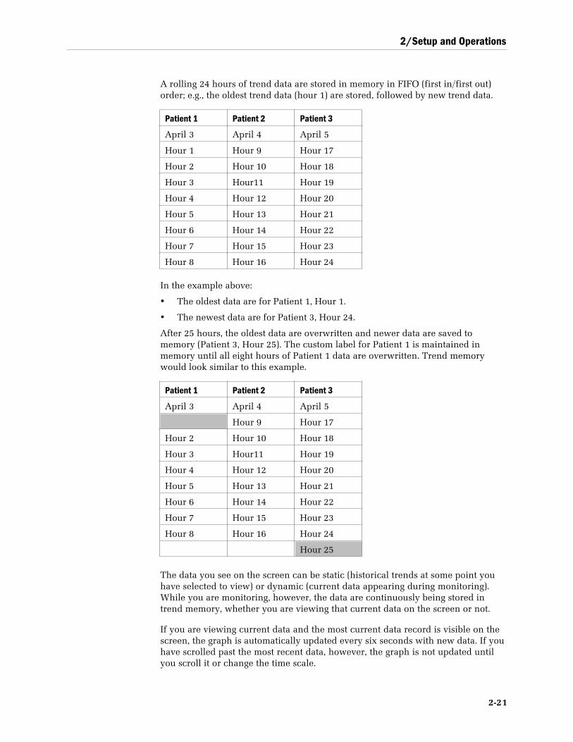
2/Setup and Operations
2-21
A rolling 24 hours of trend data are stored in memory in FIFO (first in/first out)order; e.g., the oldest trend data (hour 1) are stored, followed by new trend data.
Patient 1 Patient 2 Patient 3
April 3 April 4 April 5
Hour 1 Hour 9 Hour 17
Hour 2 Hour 10 Hour 18
Hour 3 Hour11 Hour 19
Hour 4 Hour 12 Hour 20
Hour 5 Hour 13 Hour 21
Hour 6 Hour 14 Hour 22
Hour 7 Hour 15 Hour 23
Hour 8 Hour 16 Hour 24
In the example above:
• The oldest data are for Patient 1, Hour 1.
• The newest data are for Patient 3, Hour 24.
After 25 hours, the oldest data are overwritten and newer data are saved tomemory (Patient 3, Hour 25). The custom label for Patient 1 is maintained inmemory until all eight hours of Patient 1 data are overwritten. Trend memorywould look similar to this example.
Patient 1 Patient 2 Patient 3
April 3 April 4 April 5
Hour 9 Hour 17
Hour 2 Hour 10 Hour 18
Hour 3 Hour11 Hour 19
Hour 4 Hour 12 Hour 20
Hour 5 Hour 13 Hour 21
Hour 6 Hour 14 Hour 22
Hour 7 Hour 15 Hour 23
Hour 8 Hour 16 Hour 24
Hour 25
The data you see on the screen can be static (historical trends at some point youhave selected to view) or dynamic (current data appearing during monitoring).While you are monitoring, however, the data are continuously being stored intrend memory, whether you are viewing that current data on the screen or not.
If you are viewing current data and the most current data record is visible on thescreen, the graph is automatically updated every six seconds with new data. If youhave scrolled past the most recent data, however, the graph is not updated untilyou scroll it or change the time scale.
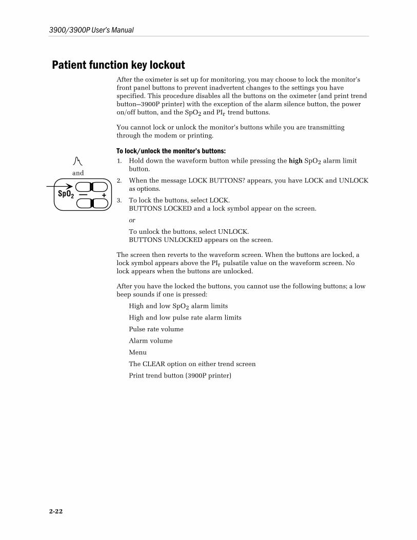
3900/3900P User’s Manual
2-22
Patient function key lockoutAfter the oximeter is set up for monitoring, you may choose to lock the monitor’sfront panel buttons to prevent inadvertent changes to the settings you havespecified. This procedure disables all the buttons on the oximeter (and print trendbutton—3900P printer) with the exception of the alarm silence button, the poweron/off button, and the SpO2 and PIr trend buttons.
You cannot lock or unlock the monitor’s buttons while you are transmittingthrough the modem or printing.
To lock/unlock the monitor’s buttons:
and
— +SpO2
1. Hold down the waveform button while pressing the high SpO2 alarm limitbutton.
2. When the message LOCK BUTTONS? appears, you have LOCK and UNLOCKas options.
3. To lock the buttons, select LOCK.BUTTONS LOCKED and a lock symbol appear on the screen.
or
To unlock the buttons, select UNLOCK.BUTTONS UNLOCKED appears on the screen.
The screen then reverts to the waveform screen. When the buttons are locked, alock symbol appears above the PIr pulsatile value on the waveform screen. Nolock appears when the buttons are unlocked.
After you have the locked the buttons, you cannot use the following buttons; a lowbeep sounds if one is pressed:
High and low SpO2 alarm limits
High and low pulse rate alarm limits
Pulse rate volume
Alarm volume
Menu
The CLEAR option on either trend screen
Print trend button (3900P printer)

3-1
3/Messages and TroubleshootingThis chapter contains
• Descriptions of the messages and indicators that appear on the screen.
• Alarm categories and their characteristics.
• A chart for troubleshooting situations that may occur while using the oximeter.
Become thoroughly familiar with this information before using the oximeter tomonitor a patient.
MessagesThe pulse oximeter acknowledges your actions and the monitor’s conditions bydisplaying messages in the waveform screen message display area. Alarmmessages appear when an alarm condition occurs. The mode you have selected(SpO2 or PIr) determines how the monitor responds to alarms when you areviewing trend data.
• If you are in SpO2 mode, an alarm causes the waveform screen to appearimmediately with the alarm condition shown in the message area.
• If you are in PIr mode, the data remain on the screen when an alarmoccurs—the alarm button will flash and the audible alarm will sound (unlessmuted). The only alarm violations that will cause the PIr mode trend screento revert to the waveform screen are system failure alarms and other alarmsthat are not patient related, such as CONNECT UNIT TO LINE POWER (ifyou are operating on battery power) or BUTTON STUCK.
The following chart alphabetically lists the messages that may appear on theoximeter, why the message appears, and the action(s) to take if the messageindicates a problem.
NOTE: Messages that appear while using a modem are listed in chapter 5.
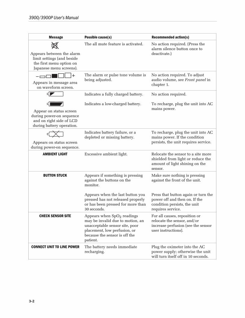
3900/3900P User’s Manual
3-2
Message Possible cause(s) Recommended action(s)
Appears between the alarmlimit settings (and besidethe first menu option onJapanese menu screens).
The all mute feature is activated. No action required. (Press thealarm silence button once todeactivate.)
Appears in message areaon waveform screen.
The alarm or pulse tone volume isbeing adjusted.
No action required. To adjustaudio volume, see Front panel inchapter 1.
Appear on status screenduring power-on sequenceand on right side of LCDduring battery operation.
Indicates a fully charged battery.
Indicates a low-charged battery.
No action required.
To recharge, plug the unit into ACmains power.
Appears on status screenduring power-on sequence.
Indicates battery failure, or adepleted or missing battery.
To recharge, plug the unit into ACmains power. If the conditionpersists, the unit requires service.
AMBIENT LIGHT Excessive ambient light. Relocate the sensor to a site moreshielded from light or reduce theamount of light shining on thesensor.
BUTTON STUCK Appears if something is pressingagainst the buttons on themonitor.
Appears when the last button youpressed has not released properlyor has been pressed for more than30 seconds.
Make sure nothing is pressingagainst the front of the unit.
Press that button again or turn thepower off and then on. If thecondition persists, the unitrequires service.
CHECK SENSOR SITE Appears when SpO2 readingsmay be invalid due to motion, anunacceptable sensor site, poorplacement, low perfusion, orbecause the sensor is off thepatient.
For all causes, reposition orrelocate the sensor, and/orincrease perfusion (see the sensoruser instructions).
CONNECT UNIT TO LINE POWER The battery needs immediaterecharging.
Plug the oximeter into the ACpower supply; otherwise the unitwill turn itself off in 10 seconds.
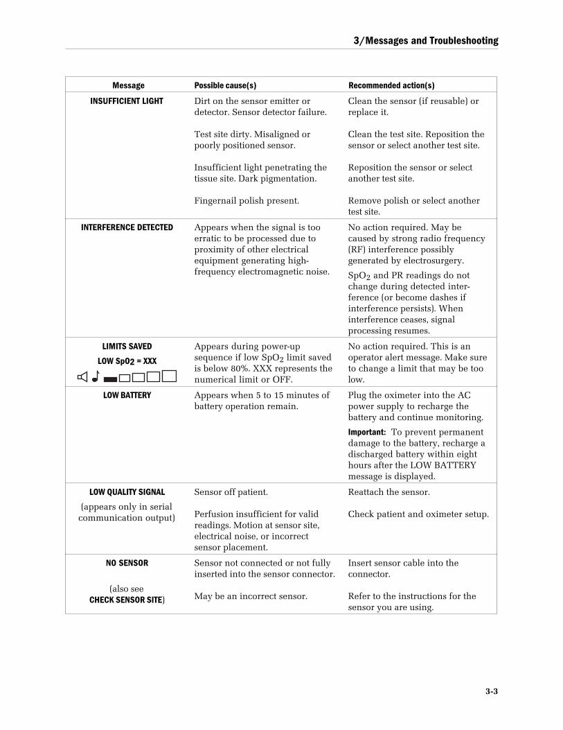
3/Messages and Troubleshooting
3-3
Message Possible cause(s) Recommended action(s)
INSUFFICIENT LIGHT Dirt on the sensor emitter ordetector. Sensor detector failure.
Test site dirty. Misaligned orpoorly positioned sensor.
Insufficient light penetrating thetissue site. Dark pigmentation.
Fingernail polish present.
Clean the sensor (if reusable) orreplace it.
Clean the test site. Reposition thesensor or select another test site.
Reposition the sensor or selectanother test site.
Remove polish or select anothertest site.
INTERFERENCE DETECTED Appears when the signal is tooerratic to be processed due toproximity of other electricalequipment generating high-frequency electromagnetic noise.
No action required. May becaused by strong radio frequency(RF) interference possiblygenerated by electrosurgery.
SpO2 and PR readings do notchange during detected inter-ference (or become dashes ifinterference persists). Wheninterference ceases, signalprocessing resumes.
LIMITS SAVED
LOW SpO2 = XXX
Appears during power-upsequence if low SpO2 limit savedis below 80%. XXX represents thenumerical limit or OFF.
No action required. This is anoperator alert message. Make sureto change a limit that may be toolow.
LOW BATTERY Appears when 5 to 15 minutes ofbattery operation remain.
Plug the oximeter into the ACpower supply to recharge thebattery and continue monitoring.
Important: To prevent permanentdamage to the battery, recharge adischarged battery within eighthours after the LOW BATTERYmessage is displayed.
LOW QUALITY SIGNAL
(appears only in serialcommunication output)
Sensor off patient.
Perfusion insufficient for validreadings. Motion at sensor site,electrical noise, or incorrectsensor placement.
Reattach the sensor.
Check patient and oximeter setup.
NO SENSOR
(also seeCHECK SENSOR SITE)
Sensor not connected or not fullyinserted into the sensor connector.
May be an incorrect sensor.
Insert sensor cable into theconnector.
Refer to the instructions for thesensor you are using.
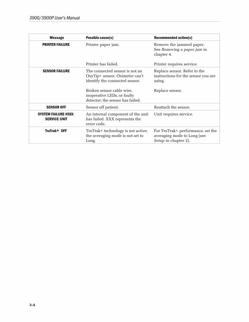
3900/3900P User’s Manual
3-4
Message Possible cause(s) Recommended action(s)
PRINTER FAILURE Printer paper jam.
Printer has failed.
Remove the jammed paper.See Removing a paper jam inchapter 4.
Printer requires service.
SENSOR FAILURE The connected sensor is not anOxyTip+ sensor. Oximeter can’tidentify the connected sensor.
Broken sensor cable wire,inoperative LEDs, or faultydetector; the sensor has failed.
Replace sensor. Refer to theinstructions for the sensor you areusing.
Replace sensor.
SENSOR OFF Sensor off patient. Reattach the sensor.
SYSTEM FAILURE #XXX:SERVICE UNIT
An internal component of the unithas failed. XXX represents theerror code.
Unit requires service.
TruTrak+ OFF TruTrak+ technology is not active;the averaging mode is not set toLong.
For TruTrak+ performance, set theaveraging mode to Long (seeSetup in chapter 2).
3/Messages and Troubleshooting
3-5
Alarm categories3900/3900P oximeter tiered alarms fall into three priority categories: high, mediumand low. Depending on what is occurring at the time, an alarm may fall into morethan one category.
NOTE: The audible alarm feature for all alarm conditions is silenced for the firsttwo minutes after powering on.
High priorityRequires immediate operator response.Red alarm button light flashes.Two five-tone sequences (beep-beep-beep, beep-beep) sound every 10 secondsuntil the condition is removed or the alarm is silenced
• A violation of the low or high SpO2 limit (violated limit flashes).
• BUTTON STUCK
• CONNECT UNIT TO LINE POWER
If the following alarms occur during active monitoring, they also fall into the highpriority category.
• AMBIENT LIGHT
• CHECK SENSOR SITE
• INSUFFICIENT LIGHT
• NO SENSOR
• SENSOR FAILURE
• SENSOR OFF
NO SENSOR and SENSOR OFF alarm conditions are not active until after theoximeter displays an initial valid reading.
Medium priorityRequires prompt operator response.Yellow alarm button light flashes.One three-tone sequence (beep-beep-beep) every 20 seconds until the condition isremoved or the alarm is silenced.
• A violation of the low or high pulse rate limit (violated limit flashes).
• INTERFERENCE DETECTED
• LOW BATTERY
• PRINTER FAILURE (3900P only)
3900/3900P User’s Manual
3-6
If the following alarms occur before active monitoring, these alarms are consideredto be of medium priority:
• AMBIENT LIGHT
• CHECK SENSOR SITE
• INSUFFICIENT LIGHT
• NO SENSOR
• SENSOR FAILURE
• SENSOR OFF
Low priorityRequires operator awareness.Yellow alarm button light illuminates continuously.One tone (beep) sounds; no repetition.
• INTERFERENCE DETECTED
Requires operator awareness.Yellow alarm button light illuminates continuously.
• LOW QUALITY SIGNAL
System failureA special category of alarms exists for system failure and the imminent failure ofpulse oximeter operation.
Requires immediate operator response.Red alarm button light continuously flashes.A continuous tone sounds; overrides all mute condition.
• SYSTEM FAILURE #XXX, SERVICE UNIT
For more information, refer to the 3800/3900/3900P Technical Reference Manual.
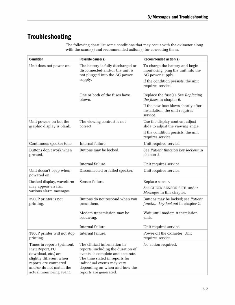
3/Messages and Troubleshooting
3-7
TroubleshootingThe following chart list some conditions that may occur with the oximeter alongwith the cause(s) and recommended action(s) for correcting them.
Condition Possible cause(s) Recommended action(s)
Unit does not power on. The battery is fully discharged ordisconnected and/or the unit isnot plugged into the AC powersupply.
One or both of the fuses haveblown.
To charge the battery and beginmonitoring, plug the unit into theAC power supply.
If the condition persists, the unitrequires service.
Replace the fuse(s). See Replacingthe fuses in chapter 6.
If the new fuse blows shortly afterinstallation, the unit requiresservice.
Unit powers on but thegraphic display is blank.
The viewing contrast is notcorrect.
Use the display contrast adjustslide to adjust the viewing angle.
If the condition persists, the unitrequires service.
Continuous speaker tone. Internal failure. Unit requires service.
Buttons don’t work whenpressed.
Buttons may be locked.
Internal failure.
See Patient function key lockout inchapter 2.
Unit requires service.
Unit doesn’t beep whenpowered on.
Disconnected or failed speaker. Unit requires service.
Dashed display, waveformmay appear erratic;various alarm messages
Sensor failure. Replace sensor.
See CHECK SENSOR SITE underMessages in this chapter.
3900P printer is notprinting.
Buttons do not respond when youpress them.
Modem transmission may beoccurring.
Internal failure
Buttons may be locked; see Patientfunction key lockout in chapter 2.
Wait until modem transmissionends.
Unit requires service.
3900P printer will not stopprinting.
Internal failure. Power off the oximeter. Unitrequires service.
Times in reports (printout,InstaReport, PCdownload, etc.) areslightly different whenreports are comparedand/or do not match theactual monitoring event.
The clinical information inreports, including the duration ofevents, is complete and accurate.The time stated in reports forindividual events may varydepending on when and how thereports are generated.
No action required.
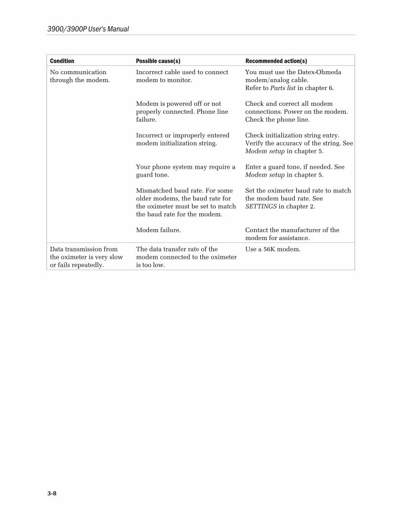
3900/3900P User’s Manual
3-8
Condition Possible cause(s) Recommended action(s)
No communicationthrough the modem.
Incorrect cable used to connectmodem to monitor.
Modem is powered off or notproperly connected. Phone linefailure.
Incorrect or improperly enteredmodem initialization string.
Your phone system may require aguard tone.
Mismatched baud rate. For someolder modems, the baud rate forthe oximeter must be set to matchthe baud rate for the modem.
Modem failure.
You must use the Datex-Ohmedamodem/analog cable.Refer to Parts list in chapter 6.
Check and correct all modemconnections. Power on the modem.Check the phone line.
Check initialization string entry.Verify the accuracy of the string. SeeModem setup in chapter 5.
Enter a guard tone, if needed. SeeModem setup in chapter 5.
Set the oximeter baud rate to matchthe modem baud rate. SeeSETTINGS in chapter 2.
Contact the manufacturer of themodem for assistance.
Data transmission fromthe oximeter is very slowor fails repeatedly.
The data transfer rate of themodem connected to the oximeteris too low.
Use a 56K modem.
4-1
4/PrinterThis chapter covers
• Operating the 3900P printer.
• Maintaining the printer.
The 3900P pulse oximeter’s integrated printer is powered on with the oximeter.You can print real-time or trend data.
You cannot print while data are being transmitted through the modem. Theprinter buttons are inactive until the transmission is completed or canceled.
NOTE: Over time, the thermal paper used in the printer darkens. To preserve theprinted data for long-term storage, make photocopies of the printouts.
Before you begin printing data, be sure you have done the following:• Selected the mode for the data you want to print: SpO2 or PIr . See MODE
under SETTINGS in chapter 2.
• Selected the time interval format for the printout: 6-second or 30-second-data-point information. See OUTPUT under SETTINGS in chapter 2.
• If you are going to print current data, make sure the correct label text isassociated with the data you are about to print. See LABELS in chapter 2.
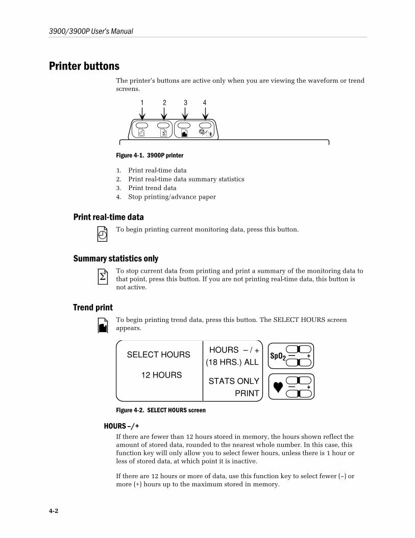
3900/3900P User’s Manual
4-2
Printer buttonsThe printer’s buttons are active only when you are viewing the waveform or trendscreens.
Σ
1 2 3 4
Figure 4-1. 3900P printer
1. Print real-time data2. Print real-time data summary statistics3. Print trend data4. Stop printing/advance paper
Print real-time dataTo begin printing current monitoring data, press this button.
Summary statistics only
ΣTo stop current data from printing and print a summary of the monitoring data tothat point, press this button. If you are not printing real-time data, this button isnot active.
Trend printTo begin printing trend data, press this button. The SELECT HOURS screenappears.
SELECT HOURS
12 HOURS
HOURS – / +
(18 HRS.) ALL
STATS ONLY
— +SpO2
— +
Figure 4-2. SELECT HOURS screen
HOURS –/+If there are fewer than 12 hours stored in memory, the hours shown reflect theamount of stored data, rounded to the nearest whole number. In this case, thisfunction key will only allow you to select fewer hours, unless there is 1 hour orless of stored data, at which point it is inactive.
If there are 12 hours or more of data, use this function key to select fewer (–) ormore (+) hours up to the maximum stored in memory.

4/Printer
4-3
(xx HRS.) ALL(XX) shows the total number of hours of data stored in memory (up to a maximumof 24 hours). To select to print all the stored data, press this function key.
STATS ONLYTo print only the summary statistics for the number of trend data hours selected,press this function key. STATS ONLY appears on the screen.
PRINTTo begin printing trend, press this function key. The message PRINTING …appears on the screen above a bar graph showing the progress of the printing. Ifyou return to the waveform screen during printing, this message appears in themessage area on that screen. When all data have printed, printing stops and thepaper advances 1.27 cm (1/2 inch).
Stop print/advance paperWhen you press this button while printing current or trend data, the printercompletes the current line of print, advances the paper 1.27 cm (1/2 inch) andstops. If you are printing trend data, ACTION NOT COMPLETED appears on theprintout.
When you are not printing, press and hold this button to advance the paperthrough the printer.
Printed data samplesFigure 4-3 shows examples of SpO2 and PIr pulsatile value printouts.
“Smart Print” featureIf a series of data points contains dashes for all parameters (SpO2, PR, and PIr ),only the first and last lines of the series print. The message NO DATA printsbetween them.
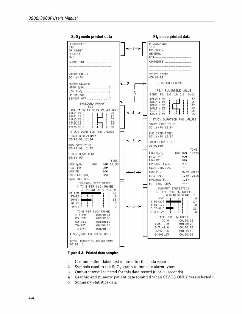
3900/3900P User’s Manual
4-4
SpO 2 mode printed data PIr mode printed data
90-10085-8980-8470-790-69
670
3300
0 20 40 60 80 100 %
12:34 8012:34 8212:34 8412:35 8612:35 8812:35 90
959580↓80↓9595
4
1
3
5
4
SpO2
90-100% 00:00:2485-89% 00:00:0080-84% 00:00:1270-79% 00:00:000-69% 00:00:00
12:34 1.5012:34 1.5012:34 0.5012:35 0.5012:35 1.5012:35 1.50
959580809595
>2.01.01-2.00.51-1.00.26-0.50.0-0.25
0670
330
0 20 40 60 80 100 %
>2.0 00:00:001.01-2.0 00:00:240.51-1.0 00:00:000.26-0.5 00:00:120.0-0.25 00:00:00
TIME PER PIr RANGE
2
5
H GONZALES110DR CASEYGENERALBY:---------------------COMMENTS:---------------------------------------------------------------STUDY DATE:05/16/98
ALARM LEGENDHIGH SpO2..............↑LOW SpO2...............↓NO SENSOR..............!SENSOR OFF.............?
6-SECOND FORMAT
% TIME PER SpO2 RANGE
TIME ♥ 50 60 70 80 90 100 SpO2
STUDY DURATION AND VALUES
START DATE/TIME:O5/16/98 12:34
END DATE/TIME:05/16/98 12:35
STUDY DURATION:00:01:00
TIMELOW SpO2 80% 84♥ 12:35HIGH PR 90♥LOW PR 80♥AVERAGE SpO2 90%SpO2 STD.DEV. ---
SUMMARY STATISTICS
TIME PER SpO2 RANGE
# SpO2 VALUES BELOW 85%:2TOTAL DURATION BELOW 85%:00:00:12
H GONZALES110DR CASEYGENERALBY:---------------------COMMENTS:---------------------------------------------------------------STUDY DATE:05/16/98
6-SECOND FORMAT
STUDY DURATION AND VALUES
START DATE/TIME:O5/16/98 12:34
END DATE/TIME:05/16/98 12:35
STUDY DURATION:00:01:00
TIMELOW SpO2 80% 84♥ 12:35HIGH PR 90♥LOW PR 80♥AVERAGE SpO2 90%SpO2 STD.DEV. ---LOW PIr 0.50 12:35HIGH PIr 1.50 12:35AVERAGE PIr 1.17PIr STD. DEV. ---
% TIME PER PIr RANGESUMMARY STATISTICS
PIr™ PULSATILE VALUETIME PIr 0.0 1.0 2.0 SpO2
Figure 4-3. Printed data samples
1 Custom patient label text entered for this data record2 Symbols used in the SpO2 graph to indicate alarm types3 Output interval selected for this data record (6 or 30 seconds)4 Graphic and numeric patient data (omitted when STATS ONLY was selected)5 Summary statistics data
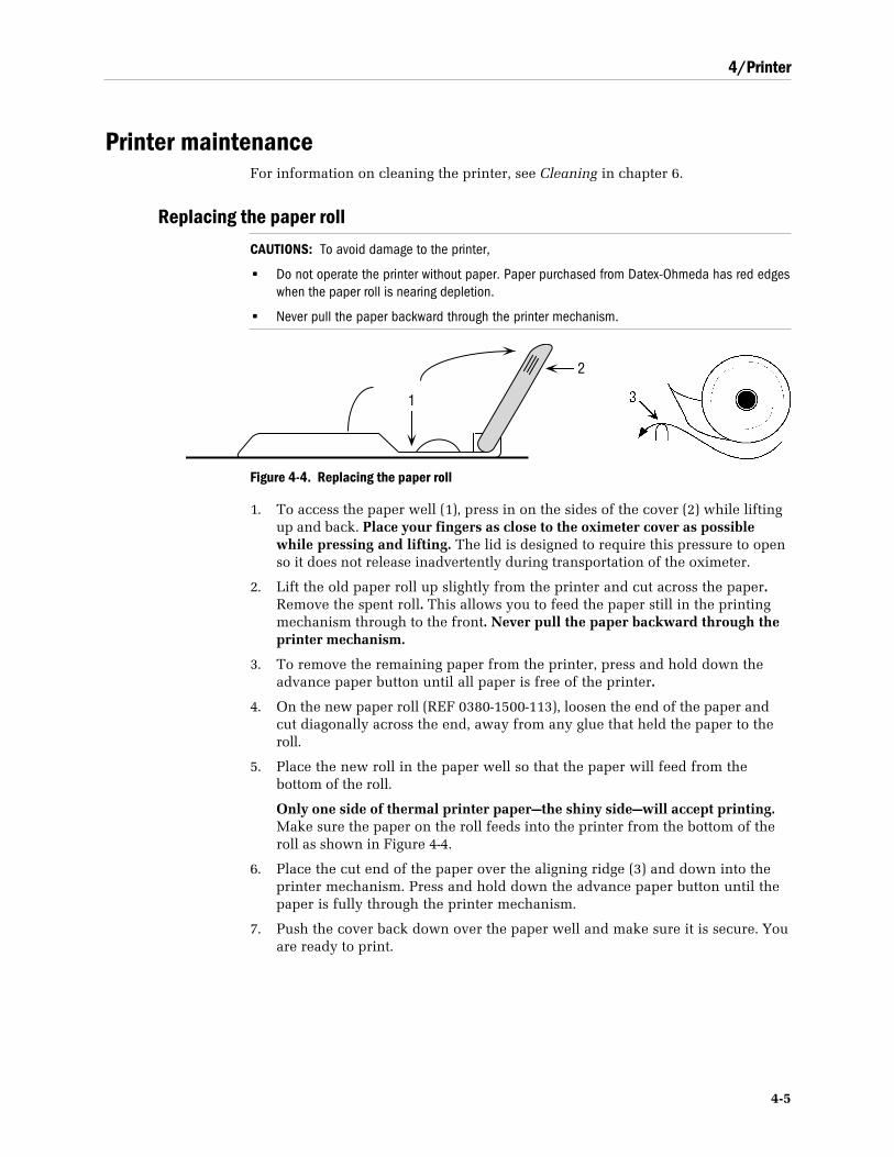
4/Printer
4-5
Printer maintenanceFor information on cleaning the printer, see Cleaning in chapter 6.
Replacing the paper roll
CAUTIONS: To avoid damage to the printer,
• Do not operate the printer without paper. Paper purchased from Datex-Ohmeda has red edgeswhen the paper roll is nearing depletion.
• Never pull the paper backward through the printer mechanism.
1
2
Figure 4-4. Replacing the paper roll
1. To access the paper well (1), press in on the sides of the cover (2) while liftingup and back. Place your fingers as close to the oximeter cover as possiblewhile pressing and lifting. The lid is designed to require this pressure to openso it does not release inadvertently during transportation of the oximeter.
2. Lift the old paper roll up slightly from the printer and cut across the paper.Remove the spent roll. This allows you to feed the paper still in the printingmechanism through to the front. Never pull the paper backward through theprinter mechanism.
3. To remove the remaining paper from the printer, press and hold down theadvance paper button until all paper is free of the printer.
4. On the new paper roll (REF 0380-1500-113), loosen the end of the paper andcut diagonally across the end, away from any glue that held the paper to theroll.
5. Place the new roll in the paper well so that the paper will feed from thebottom of the roll.
Only one side of thermal printer paper—the shiny side—will accept printing.Make sure the paper on the roll feeds into the printer from the bottom of theroll as shown in Figure 4-4.
6. Place the cut end of the paper over the aligning ridge (3) and down into theprinter mechanism. Press and hold down the advance paper button until thepaper is fully through the printer mechanism.
7. Push the cover back down over the paper well and make sure it is secure. Youare ready to print.
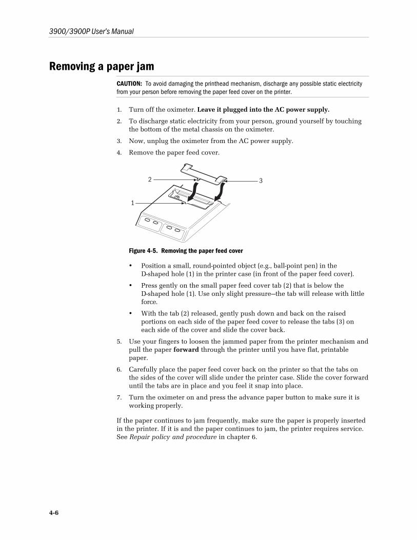
3900/3900P User’s Manual
4-6
Removing a paper jamCAUTION: To avoid damaging the printhead mechanism, discharge any possible static electricityfrom your person before removing the paper feed cover on the printer.
1. Turn off the oximeter. Leave it plugged into the AC power supply.
2. To discharge static electricity from your person, ground yourself by touchingthe bottom of the metal chassis on the oximeter.
3. Now, unplug the oximeter from the AC power supply.
4. Remove the paper feed cover.
2
1
3
Figure 4-5. Removing the paper feed cover
• Position a small, round-pointed object (e.g., ball-point pen) in theD-shaped hole (1) in the printer case (in front of the paper feed cover).
• Press gently on the small paper feed cover tab (2) that is below theD-shaped hole (1). Use only slight pressure—the tab will release with littleforce.
• With the tab (2) released, gently push down and back on the raisedportions on each side of the paper feed cover to release the tabs (3) oneach side of the cover and slide the cover back.
5. Use your fingers to loosen the jammed paper from the printer mechanism andpull the paper forward through the printer until you have flat, printablepaper.
6. Carefully place the paper feed cover back on the printer so that the tabs onthe sides of the cover will slide under the printer case. Slide the cover forwarduntil the tabs are in place and you feel it snap into place.
7. Turn the oximeter on and press the advance paper button to make sure it isworking properly.
If the paper continues to jam frequently, make sure the paper is properly insertedin the printer. If it is and the paper continues to jam, the printer requires service.See Repair policy and procedure in chapter 6.
5-1
5/TeleOximetryThis chapter covers
• Connecting a modem to the 3900/3900P.
• Selecting the data to be transmitted.
• Sending a fax through a fax modem.
• Sending data through the modem to a remote computer.
• Setting up the 3900/3900P for your modem.
Sample reports are included at the end of the chapter.
Using a modem: summaryYou cannot transmit data through a modem while printing. Complete oneoperation, then begin the other.
If you use a fax modem, you can transmit data to a fax machine.
The steps for using a modem to transmit trend data are summarized below.Details for performing these steps and descriptions of messages that may bedisplayed are included in this chapter, except as noted below.
1. Connect your modem.
2. Press the Menu button to display the MENU screen.
3. Select SETTINGS, then MODE to choose the trend data (PIr or SpO2) to betransmitted.
For remote computer transmissions, select the BAUD RATE. See SETTINGS inchapter 2.
4. Select MODEM to display the MODEM STATUS screen.
5. Choose SELECT DATA and select the number of hours of data to betransmitted.
6. Select SEND to display the SEND screen.
7. Select FAX or REMOTE COMPUTER, enter the phone number, and selectSEND.
or
Select WAIT FOR CALL.
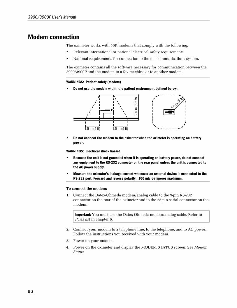
3900/3900P User’s Manual
5-2
Modem connectionThe oximeter works with 56K modems that comply with the following:
• Relevant international or national electrical safety requirements.
• National requirements for connection to the telecommunications system.
The oximeter contains all the software necessary for communication between the3900/3900P and the modem to a fax machine or to another modem.
WARNINGS: Patient safety (modem)
• Do not use the modem within the patient environment defined below:
1.5 m (5 ft)1.5 m (5 ft)
1.5 m
(5 ft)
2.5
m (8
.2 ft
)• Do not connect the modem to the oximeter when the oximeter is operating on battery
power.
WARNINGS: Electrical shock hazard
• Because the unit is not grounded when it is operating on battery power, do not connectany equipment to the RS-232 connector on the rear panel unless the unit is connected tothe AC power supply.
• Measure the oximeter’s leakage current whenever an external device is connected to theRS-232 port. Forward and reverse polarity: 100 microamperes maximum.
To connect the modem:
1. Connect the Datex-Ohmeda modem/analog cable to the 9-pin RS-232connector on the rear of the oximeter and to the 25-pin serial connector on themodem.
Important: You must use the Datex-Ohmeda modem/analog cable. Refer toParts list in chapter 6.
2. Connect your modem to a telephone line, to the telephone, and to AC power.Follow the instructions you received with your modem.
3. Power on your modem.
4. Power on the oximeter and display the MODEM STATUS screen. See ModemStatus.
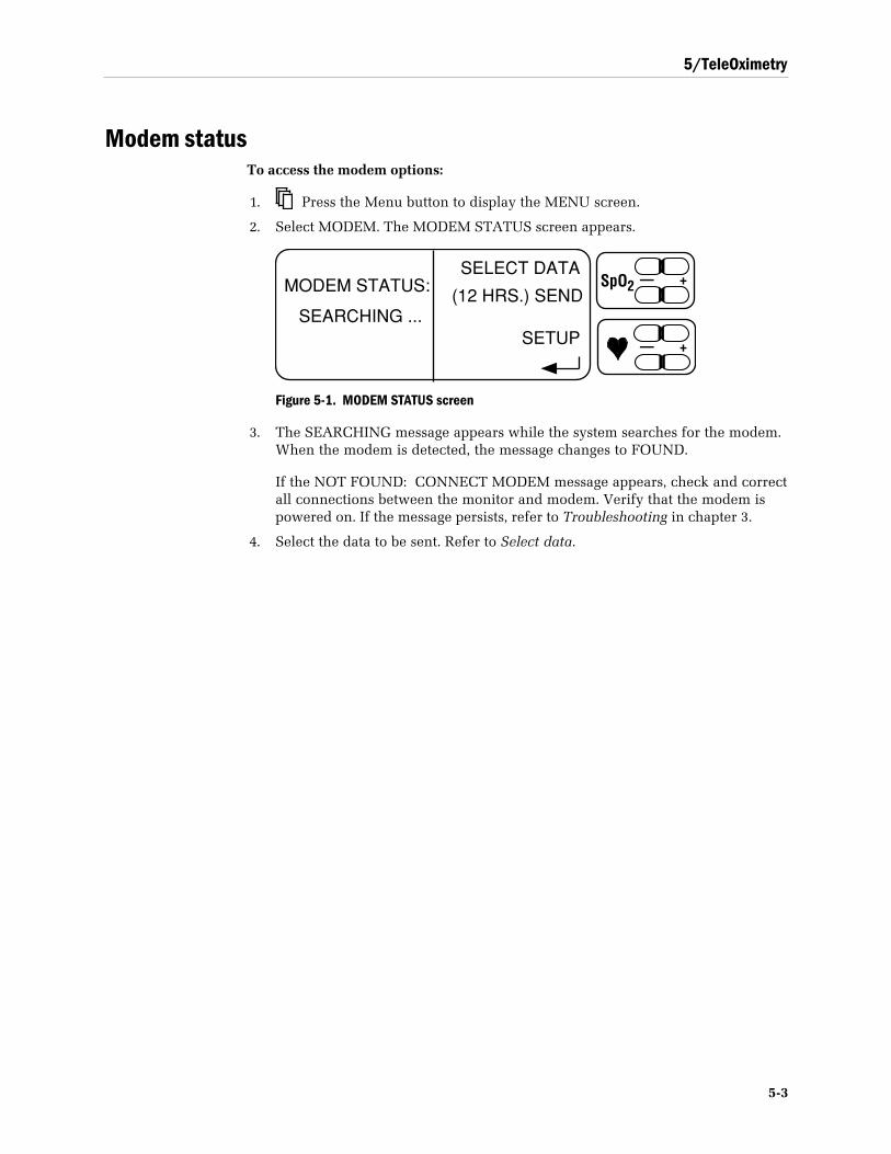
5/TeleOximetry
5-3
Modem statusTo access the modem options:
1. Press the Menu button to display the MENU screen.
2. Select MODEM. The MODEM STATUS screen appears.
MODEM STATUS:SELECT DATA
(12 HRS.) SEND
SETUPSEARCHING ...
— +SpO2
— +
Figure 5-1. MODEM STATUS screen
3. The SEARCHING message appears while the system searches for the modem.When the modem is detected, the message changes to FOUND.
If the NOT FOUND: CONNECT MODEM message appears, check and correctall connections between the monitor and modem. Verify that the modem ispowered on. If the message persists, refer to Troubleshooting in chapter 3.
4. Select the data to be sent. Refer to Select data.
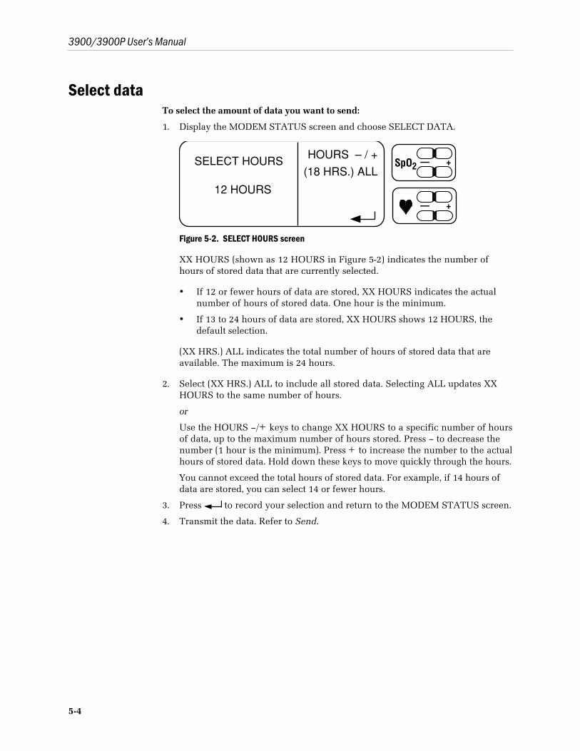
3900/3900P User’s Manual
5-4
Select dataTo select the amount of data you want to send:
1. Display the MODEM STATUS screen and choose SELECT DATA.
SELECT HOURS
12 HOURS
HOURS – / +
(18 HRS.) ALL— +SpO2
— +
Figure 5-2. SELECT HOURS screen
XX HOURS (shown as 12 HOURS in Figure 5-2) indicates the number ofhours of stored data that are currently selected.
• If 12 or fewer hours of data are stored, XX HOURS indicates the actualnumber of hours of stored data. One hour is the minimum.
• If 13 to 24 hours of data are stored, XX HOURS shows 12 HOURS, thedefault selection.
(XX HRS.) ALL indicates the total number of hours of stored data that areavailable. The maximum is 24 hours.
2. Select (XX HRS.) ALL to include all stored data. Selecting ALL updates XXHOURS to the same number of hours.
or
Use the HOURS –/+ keys to change XX HOURS to a specific number of hoursof data, up to the maximum number of hours stored. Press – to decrease thenumber (1 hour is the minimum). Press + to increase the number to the actualhours of stored data. Hold down these keys to move quickly through the hours.
You cannot exceed the total hours of stored data. For example, if 14 hours ofdata are stored, you can select 14 or fewer hours.
3. Press to record your selection and return to the MODEM STATUS screen.
4. Transmit the data. Refer to Send.
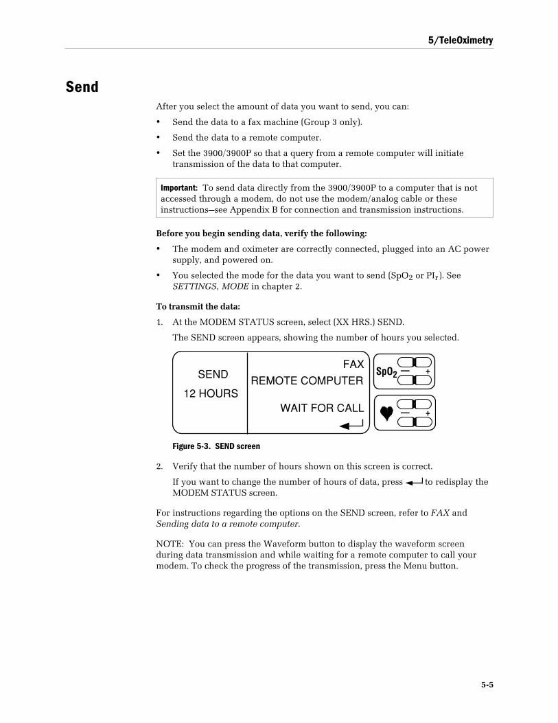
5/TeleOximetry
5-5
SendAfter you select the amount of data you want to send, you can:
• Send the data to a fax machine (Group 3 only).
• Send the data to a remote computer.
• Set the 3900/3900P so that a query from a remote computer will initiatetransmission of the data to that computer.
Important: To send data directly from the 3900/3900P to a computer that is notaccessed through a modem, do not use the modem/analog cable or theseinstructions—see Appendix B for connection and transmission instructions.
Before you begin sending data, verify the following:
• The modem and oximeter are correctly connected, plugged into an AC powersupply, and powered on.
• You selected the mode for the data you want to send (SpO2 or PIr). SeeSETTINGS, MODE in chapter 2.
To transmit the data:
1. At the MODEM STATUS screen, select (XX HRS.) SEND.
The SEND screen appears, showing the number of hours you selected.
SENDFAX
REMOTE COMPUTER
WAIT FOR CALL12 HOURS
— +SpO2
— +
Figure 5-3. SEND screen
2. Verify that the number of hours shown on this screen is correct.
If you want to change the number of hours of data, press to redisplay theMODEM STATUS screen.
For instructions regarding the options on the SEND screen, refer to FAX andSending data to a remote computer.
NOTE: You can press the Waveform button to display the waveform screenduring data transmission and while waiting for a remote computer to call yourmodem. To check the progress of the transmission, press the Menu button.

3900/3900P User’s Manual
5-6
FAXThe fax feature requires the use of a Class 1 fax modem to send a fax to a Group 3fax machine only.
To send data to a fax machine:
1. From the SEND screen, select FAX.
2. The PHONE NUMBER screen is displayed. Enter the phone number for thefax machine.
––––––––––––––––––––
––––––––––––––––––––
SEND
PHONE NUMBER– / +
CLEAR
— +SpO2
— +
Figure 5-4. PHONE NUMBER screen
The first time this screen appears, the phone number field is blank. Thenumber you enter appears the next time this screen is displayed.
You can edit an existing number or select CLEAR to remove it from thescreen, then enter a new number. If the number is long, continue it on thenext line.
Use and to move the cursor. Hold down the key to move quickly.
Use – and + to move in descending (–) or ascending (+) order to the newcharacter. Hold down the key to scroll quickly through the availablecharacters:
0 1 2 3 4 5 6 7 8 9 * # T P W , (comma) / ! @ – <space>
T = sends a tone dial (as from a push-button, or touch-tone, phone). Sincetone dial is the default for most modems, T is usually not needed.
P = sends a pulse dial (as from a rotary dial phone).
W or , (comma) = activates a pause that may be necessary on your phoneline before you can dial the rest of the phone number.
Example:P9,1236574 indicates you are using a pulse dial phone from which youmust dial 9 to access an outside line, wait for the dial tone, then dial thephone number.
Dashes and forward slashes are accepted, but not required. For an explanationof the other characters you can use in the number string, refer to theinstructions for your modem.
3. After entering the phone number of the fax machine, press SEND.

5/TeleOximetry
5-7
Fax transmission messagesAfter you press SEND to transmit a fax, some or all of the following messages maybe displayed:
DIALING REMOTE FAX—the modem is dialing the number.
BUSY—the fax machine is busy. The modem redials the number until the faxmachine is no longer busy or until you press CANCEL.
CONNECTING—the FAX machine has answered the phone.
SENDING FAX—the connection process is complete.
SENDING FAX ...
PAGE 1 OF 2 CANCEL
52%
— +SpO2
— +
Figure 5-5. SENDING FAX screen
A bar graph shows the progress of the transmission. The percentage of datatransmitted, the number of pages faxed, and the total number of pages to befaxed are shown below the bar graph.
The page is sent again if the fax machine reports poor page quality. The bargraph shrinks accordingly. The percentage sent and page number referencereflect the new status.
FAX DONE—transmission is complete. The modem disconnects the phone line.Press to display the SEND screen.
If the transmission is interrupted, refer to Transmission failure messages later inthis chapter.
Canceling a transmission (FAX CANCELED)If you select CANCEL while transmitting data, transmission stops and the modemdisconnects the phone line.
When you cancel a fax transmission, the FAX CANCELED message is displayedon the screen and transmitted to the fax machine.
Press to return to the SEND screen.
3900/3900P User’s Manual
5-8
Sending data to a remote computerWhen connected to an external modem, the 3900/3900P supports the transmissionof up to 24 hours of trend data over public telephone lines to a modem-equippedremote computer. The telephone connection may be initiated by the remotecomputer or by the 3900/3900P.
Remote computer requirementsYour remote computer must be equipped with a serial communications softwareprogram (e.g., ProComm Plus by Data Storm Technologies) or a terminalemulation program, such as those that are incorporated within some operatingsystems (e.g., the Microsoft Windows Terminal program in Windows 3.1 or theMicrosoft Hyper Terminal program in Windows 95 and Windows NT).
Data are transmitted to a remote computer using the Xmodem or Xmodem/CRCprotocol. The communications program should support one of these protocols.
Preparing for transmissionThe user of the remote computer may need to set up the remote computermodem as described in the instructions for the modem. Before trend data can betransferred, the remote computer user must set up the communications programand verify that it is configured as follows:
• No parity, 8 data bits, 1 start bit, 1 stop bit, full duplex, and hardware flowcontrol.
• Baud rate of 9600, 19.2K, 38.4K, or 57.6K BPS.
Important: The communications program and the oximeter must use the samebaud rate. To set the 3900/3900P baud rate, see SETTINGS in chapter 2.
Dialing and answering calls at the remote computerConsult the instructions for the communications program used on the remotecomputer for details regarding dialing and answering features.
• To initiate a call from the remote computer, the remote computer user willneed to set up the dialing features of the communications program.
• To receive a call from the 3900/3900P, the remote computer user may need tocomplete the connection by answering the call. Some communicationsprograms may require the user to type the modem command for answeringan incoming call: ATA <return>
Receiving the data file at the remote computerThe remote computer user must select the Xmodem or Xmodem/CRC binarytransfer protocol to receive a data file from the 3900/3900P. It is recommendedthat the received data be saved to a file on the remote computer. Saving data to afile is supported by most communications programs and is activated by thecomputer user. Although a successfully transferred data file can be viewed andedited as an ASCII file, if the computer user must choose either ASCII or binary,the user should select binary.
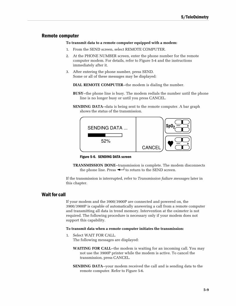
5/TeleOximetry
5-9
Remote computerTo transmit data to a remote computer equipped with a modem:
1. From the SEND screen, select REMOTE COMPUTER.
2. At the PHONE NUMBER screen, enter the phone number for the remotecomputer modem. For details, refer to Figure 5-4 and the instructionsimmediately after it.
3. After entering the phone number, press SEND.Some or all of these messages may be displayed:
DIAL REMOTE COMPUTER—the modem is dialing the number.
BUSY—the phone line is busy. The modem redials the number until the phoneline is no longer busy or until you press CANCEL.
SENDING DATA—data is being sent to the remote computer. A bar graphshows the status of the transmission.
SENDING DATA ...
CANCEL
— +SpO2
— +52%
Figure 5-6. SENDING DATA screen
TRANSMISSION DONE—transmission is complete. The modem disconnectsthe phone line. Press to return to the SEND screen.
If the transmission is interrupted, refer to Transmission failure messages later inthis chapter.
Wait for callIf your modem and the 3900/3900P are connected and powered on, the3900/3900P is capable of automatically answering a call from a remote computerand transmitting all data in trend memory. Intervention at the oximeter is notrequired. The following procedure is necessary only if your modem does notsupport this capability.
To transmit data when a remote computer initiates the transmission:
1. Select WAIT FOR CALL.The following messages are displayed:
WAITING FOR CALL—the modem is waiting for an incoming call. You maynot use the 3900P printer while the modem is active. To cancel thetransmission, press CANCEL.
SENDING DATA—your modem received the call and is sending data to theremote computer. Refer to Figure 5-6.
3900/3900P User’s Manual
5-10
TRANSMISSION DONE—transmission is complete. The modem disconnectsthe phone line. Press to return to the SEND screen.
If the transmission is interrupted, refer to Transmission failure messages later inthis chapter.
Canceling a transmission (TRANSMISSION CANCELED)If you select CANCEL while transmitting data, transmission stops and the modemdisconnects the phone line.
When you cancel a remote computer transmission, the TRANSMISSIONCANCELED message is displayed on the screen and transmitted to the remotecomputer. Press to return to the SEND screen.
Transmission failure messagesFor each of the following conditions, the modem disconnects the phone line (if aconnection was achieved before the transmission failed). You can press toreturn to the SEND screen.
CONNECTION FAILURE—the modem cannot contact the fax machine or remotecomputer. Verify that the number was entered correctly and the remoteequipment (fax machine, modem and/or computer) is powered on. Your phonesystem may require a guard tone. See Modem setup later in this chapter.
FAX ERROR—a nonrecoverable error occurred during transmission of a fax. Thismessage indicates a problem with your modem, the phone line, or the faxmachine. Check the function of all these components. Verify that you arefaxing to a Group 3 fax machine.
INITIALIZATION STRING FAILURE—the modem rejected the initializationstring. Make sure you entered the initialization string correctly. Refer toModem setup, Custom initialization string later in this chapter. If the entry iscorrect, consult the instructions for your modem.
NO ANSWER—there is no answer after the number is dialed. Verify that youentered the number correctly and the remote equipment (fax machine,modem and/or computer) is powered on.
NO DATA—you tried to send a fax that covered only hours during which nonumeric data were collected. For example, if numeric data were collected twohours earlier, but not during the last hour of operation, you can send two ormore hours of data, but not one. This eliminates the possibility of sending anInstaReport that contains no numeric data.
NO DIAL TONE—the modem cannot find a dial tone when attempting to call thenumber. Verify that the correct phone lines are properly connected to themodem.
TRANSMISSION ERROR—a nonrecoverable error occurred during transmission.This message indicates a problem with your modem, the phone line, theremote modem, or the remote computer. Check the function of all thesecomponents.
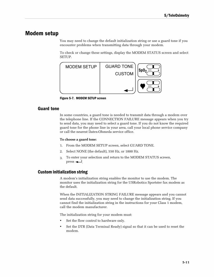
5/TeleOximetry
5-11
Modem setupYou may need to change the default initialization string or use a guard tone if youencounter problems when transmitting data through your modem.
To check or change these settings, display the MODEM STATUS screen and selectSETUP.
MODEM SETUP GUARD TONE
CUSTOM— +SpO2
— +
Figure 5-7. MODEM SETUP screen
Guard toneIn some countries, a guard tone is needed to transmit data through a modem overthe telephone line. If the CONNECTION FAILURE message appears when you tryto send data, you may need to select a guard tone. If you do not know the requiredguard tone for the phone line in your area, call your local phone service companyor call the nearest Datex-Ohmeda service office.
To choose a guard tone:
1. From the MODEM SETUP screen, select GUARD TONE.
2. Select NONE (the default), 550 Hz, or 1800 Hz.
3. To enter your selection and return to the MODEM STATUS screen,press .
Custom initialization stringA modem’s initialization string enables the monitor to use the modem. Themonitor uses the initialization string for the USRobotics Sportster fax modem asthe default.
When the INITIALIZATION STRING FAILURE message appears and you cannotsend data successfully, you may need to change the initialization string. If youcannot find the initialization string in the instructions for your Class 1 modem,call the modem manufacturer.
The initialization string for your modem must:
• Set the flow control to hardware only.
• Set the DTR (Data Terminal Ready) signal so that it can be used to reset themodem.
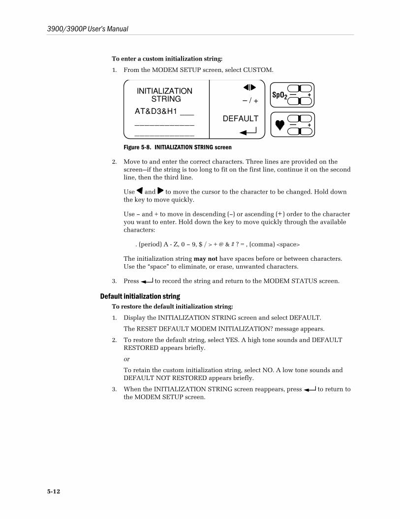
3900/3900P User’s Manual
5-12
To enter a custom initialization string:
1. From the MODEM SETUP screen, select CUSTOM.
– / +
DEFAULT
INITIALIZATIONSTRING
— +SpO2
— +
AT&D3&H1 ___________________________
Figure 5-8. INITIALIZATION STRING screen
2. Move to and enter the correct characters. Three lines are provided on thescreen—if the string is too long to fit on the first line, continue it on the secondline, then the third line.
Use and to move the cursor to the character to be changed. Hold downthe key to move quickly.
Use – and + to move in descending (–) or ascending (+) order to the characteryou want to enter. Hold down the key to move quickly through the availablecharacters:
. (period) A - Z, 0 – 9, $ / > + @ & # ? = , (comma) <space>
The initialization string may not have spaces before or between characters.Use the “space” to eliminate, or erase, unwanted characters.
3. Press to record the string and return to the MODEM STATUS screen.
Default initialization stringTo restore the default initialization string:
1. Display the INITIALIZATION STRING screen and select DEFAULT.
The RESET DEFAULT MODEM INITIALIZATION? message appears.
2. To restore the default string, select YES. A high tone sounds and DEFAULTRESTORED appears briefly.
or
To retain the custom initialization string, select NO. A low tone sounds andDEFAULT NOT RESTORED appears briefly.
3. When the INITIALIZATION STRING screen reappears, press to return tothe MODEM SETUP screen.
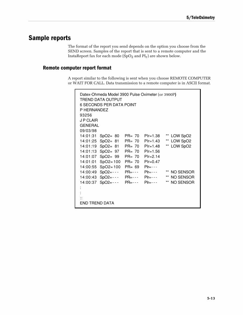
5/TeleOximetry
5-13
Sample reportsThe format of the report you send depends on the option you choose from theSEND screen. Samples of the report that is sent to a remote computer and theInstaReport fax for each mode (SpO2 and PIr) are shown below.
Remote computer report format
A report similar to the following is sent when you choose REMOTE COMPUTERor WAIT FOR CALL. Data transmission to a remote computer is in ASCII format.
Datex-Ohmeda Model 3900 Pulse Oximeter (or 3900P)TREND DATA OUTPUT6 SECONDS PER DATA POINTP HERNANDEZ93256J P CLAIRGENERAL09/03/9814:01:31 SpO2= 80 PR= 70 PIr=1.38 ** LOW SpO214:01:25 SpO2= 81 PR= 70 PIr=1.43 ** LOW SpO214:01:19 SpO2= 81 PR= 70 PIr=1.48 ** LOW SpO214:01:13 SpO2= 97 PR= 70 PIr=1.5614:01:07 SpO2= 99 PR= 70 PIr=2.1414:01:01 SpO2= 100 PR= 70 PIr=0.4714:00:55 SpO2= 100 PR= 69 PIr= - - -14:00:49 SpO2= - - - PR= - - - PIr= - - - ** NO SENSOR14:00:43 SpO2= - - - PR= - - - PIr= - - - ** NO SENSOR14:00:37 SpO2= - - - PR= - - - PIr= - - - ** NO SENSOR::::END TREND DATA
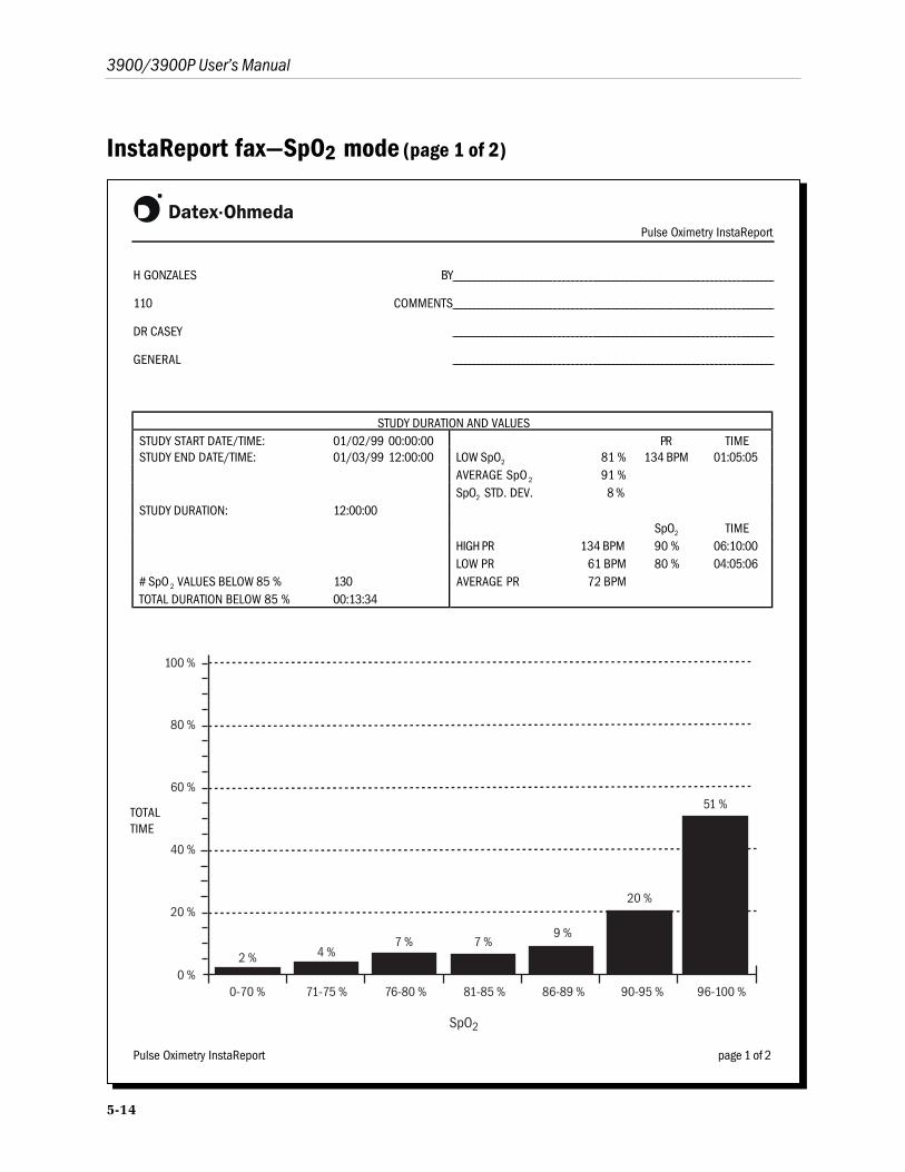
3900/3900P User’s Manual
5-14
InstaReport fax—SpO2 mode (page 1 of 2)
Pulse Oximetry InstaReport
H GONZALES BY
110 COMMENTS
DR CASEY
GENERAL
STUDY DURATION AND VALUESSTUDY START DATE/TIME: 01/02/99 00:00:00 PR TIMESTUDY END DATE/TIME: 01/03/99 12:00:00 LOW SpO2 81 % 134 BPM 01:05:05
AVERAGE SpO 2 91 %SpO2 STD. DEV. 8 %
STUDY DURATION: 12:00:00SpO2 TIME
HIGH PR 134 BPM 90 % 06:10:00LOW PR 61 BPM 80 % 04:05:06
# SpO 2 VALUES BELOW 85 % 130 AVERAGE PR 72 BPMTOTAL DURATION BELOW 85 % 00:13:34
0-70 % 71-75 % 76-80 % 81-85 % 86-89 % 90-95 % 96-100 %0 %
20 %
40 %
60 %
80 %
100 %
51 %
20 %
9 %7 %7 %
4 %2 %
SpO2
Pulse Oximetry InstaReport page 1 of 2
TOTALTIME
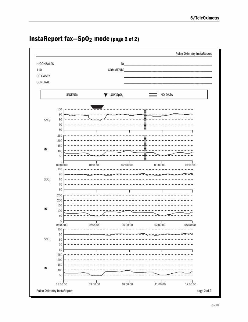
5/TeleOximetry
5-15
InstaReport fax—SpO2 mode (page 2 of 2)
Pulse Oximetry InstaReport
H GONZALES BY
110 COMMENTS
DR CASEY
GENERAL
LEGEND: LOW SpO2 NO DATA
60
70
80
90
100
60
70
80
90
100
04:00:00 05:00:00 06:00:00 07:00:00 08:00:000
50
100
150
200
250
60
70
80
90
100
08:00:00 09:00:00 10:00:00 11:00:00 12:00:000
50
100
150
200
250
00:00:00 01:00:00 02:00:00 03:00:00 04:00:000
50
100
150
200
250
Pulse Oximetry InstaReport page 2 of 2
SpO2
SpO2
SpO2
PR
PR
PR
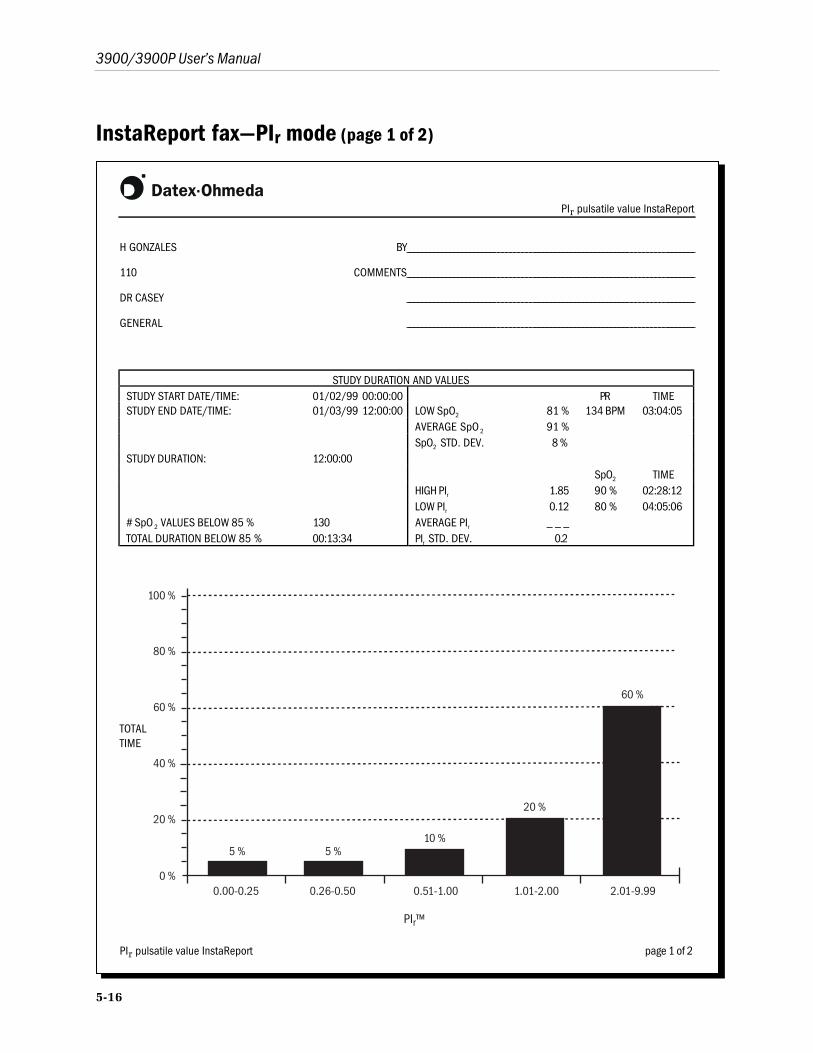
3900/3900P User’s Manual
5-16
InstaReport fax—PIr mode (page 1 of 2)
PIr pulsatile value InstaReport
H GONZALES BY
110 COMMENTS
DR CASEY
GENERAL
STUDY DURATION AND VALUESSTUDY START DATE/TIME: 01/02/99 00:00:00 PR TIMESTUDY END DATE/TIME: 01/03/99 12:00:00 LOW SpO2 81 % 134 BPM 03:04:05
AVERAGE SpO 2 91 %SpO2 STD. DEV. 8 %
STUDY DURATION: 12:00:00SpO2 TIME
HIGH PIr 1.85 90 % 02:28:12LOW PIr 0.12 80 % 04:05:06
# SpO 2 VALUES BELOW 85 % 130 AVERAGE PIr _ _ _TOTAL DURATION BELOW 85 % 00:13:34 PIr STD. DEV. 0.2
0.00-0.25 0.26-0.50 0.51-1.00 1.01-2.00 2.01-9.990 %
20 %
40 %
60 %
80 %
100 %
60 %
20 %
10 %5 %5 %
PIr™
PIr pulsatile value InstaReport page 1 of 2
TOTALTIME
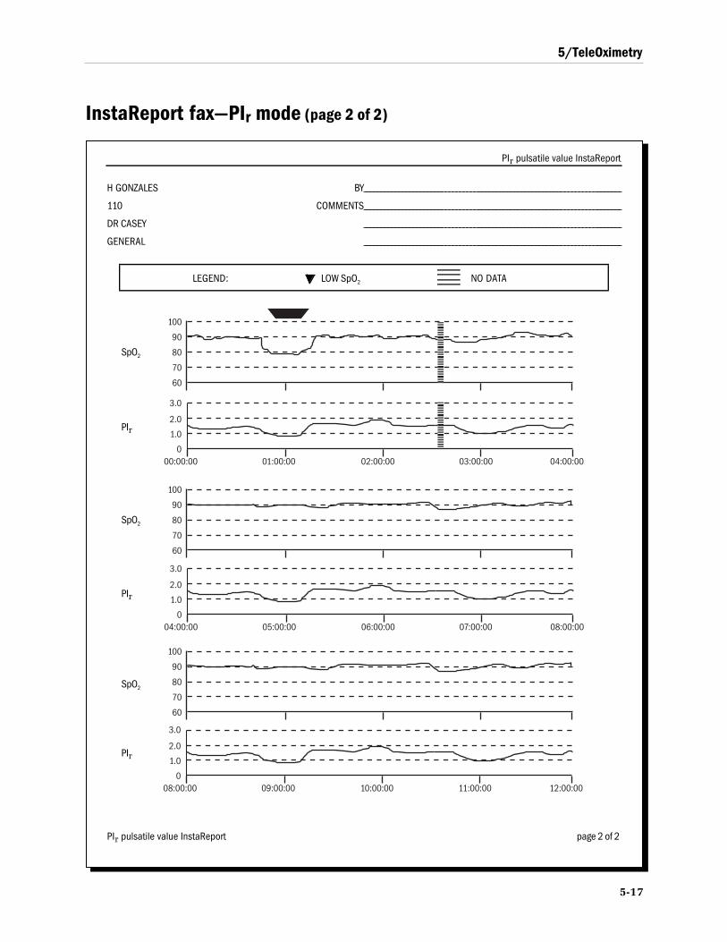
5/TeleOximetry
5-17
InstaReport fax—PIr mode (page 2 of 2)
PIr pulsatile value InstaReport
H GONZALES BY
110 COMMENTS
DR CASEY
GENERAL
LEGEND: LOW SpO2 NO DATA
08:00:00 09:00:00 10:00:00 11:00:00 12:00:000
1.0
2.0
3.0
04:00:00 05:00:00 06:00:00 07:00:00 08:00:000
1.0
2.0
3.0
60
70
80
90
100
60
70
80
90
100
00:00:00 01:00:00 02:00:00 03:00:00 04:00:000
1.0
2.0
3.0
60
70
80
90
100
PIr pulsatile value InstaReport page 2 of 2
PIr
SpO2
PIr
SpO2
PIr
SpO2

3900/3900P User’s Manual
5-18

6-1
6/Maintenance and ServiceThis chapter covers
• Maintenance procedures:
Cleaning the oximeter, as necessary.
Recharging the battery, as necessary.
Replacing the fuses in the power module, as necessary.
• The Datex-Ohmeda repair policy.
• A list of items you may order for the oximeter.
To replace the paper roll in the printer, see chapter 4.
CleaningTo clean the modem, refer to the instructions for the modem you are using. Toclean a reusable sensor, refer to the instructions for the sensor.
Oximeter (with or without the printer)
WARNING: Electrical shock and flammability hazard. Before cleaning the oximeter, always turnit off and disconnect the power cord from the AC power supply.
CAUTION:
• Do not autoclave, pressure sterilize, or gas sterilize this oximeter.
• Use cleaning solution sparingly. Do not soak or immerse the monitor in liquid. Excessivesolution can flow into the monitor and damage internal components.
• When cleaning the display area, do not use abrasive cleaning compounds or other materialsthat could damage the screen.
• Do not use petroleum-based solutions, acetone solutions, or other harsh solvents to cleanthe oximeter. These substances may damage the oximeter and cause a malfunction.
Be sure that the oximeter is turned off and unplugged from the AC power supplybefore cleaning and that the unit is completely dry before use.
To clean the display panel, use a cotton swab moistened with 70% isopropylalcohol and gently wipe the panel.
3900/3900P User’s Manual
6-2
To clean the outer surface of the oximeter, use a soft cloth dampened with a mildsoap and water solution or one of the following solutions:
70 vol% isopropyl or ethyl alcohol
quaternary ammonia
3 vol% hydrogen peroxide in water
100:1 bleach solution
Cidex® plus activator (ready solution contains 2 vol% glutaraldehyde)
Sodium hypochlorite solution (5 vol%)
CAUTION: To prevent damage to the 3900P printer, do not allow any cleaning solution to get intothe printer mechanism.
Recharging the batteryThe oximeter's internal battery (a sealed pack of 8V lead-acid batteries) providesthe following operation times when it is new, used at normal temperatures, andcharged to full capacity:
• 3900/3900P: at least 5 -1/2 hours of continuous operation.
• 3900P: approximately 4 hours of operation when printing.
A LOW BATTERY message appears when 5 to 15 minutes of battery operationremain. When the alarm message CONNECT UNIT TO LINE POWER appearsduring operation on battery power, an audible alarm sounds and the oximeterautomatically shuts off in approximately 10 seconds.
Important: To prevent permanent damage to the battery, recharge a dischargedbattery within eight hours after the LOW BATTERY message is displayed.
To recharge the battery, plug the oximeter into the AC power supply. Theoximeter is operational while recharging the battery.
The battery charging times are approximately
• 4 hours for 80% battery capacity.
• 8 hours for 100% battery capacity.
Under normal conditions, the battery lasts for several hundred charge/dischargecycles. The battery will not overcharge.
Batteries stored for extended periods of time should be recharged every sixmonths to maintain the charging capacity of the battery.
Replacing the batteryIf the battery will no longer recharge with AC power connected, it should bereplaced. Battery replacement should be performed by authorized servicepersonnel only.
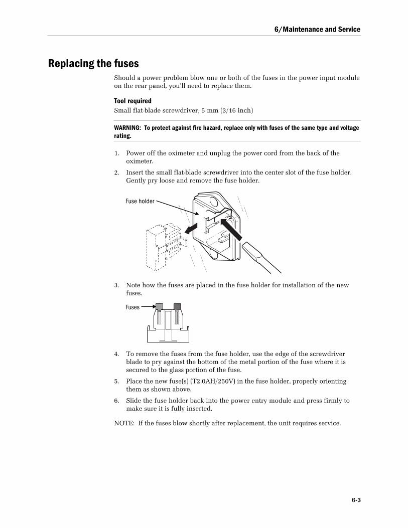
6/Maintenance and Service
6-3
Replacing the fusesShould a power problem blow one or both of the fuses in the power input moduleon the rear panel, you’ll need to replace them.
Tool requiredSmall flat-blade screwdriver, 5 mm (3/16 inch)
WARNING: To protect against fire hazard, replace only with fuses of the same type and voltagerating.
1. Power off the oximeter and unplug the power cord from the back of theoximeter.
2. Insert the small flat-blade screwdriver into the center slot of the fuse holder.Gently pry loose and remove the fuse holder.
3. Note how the fuses are placed in the fuse holder for installation of the newfuses.
4. To remove the fuses from the fuse holder, use the edge of the screwdriverblade to pry against the bottom of the metal portion of the fuse where it issecured to the glass portion of the fuse.
5. Place the new fuse(s) (T2.0AH/250V) in the fuse holder, properly orientingthem as shown above.
6. Slide the fuse holder back into the power entry module and press firmly tomake sure it is fully inserted.
NOTE: If the fuses blow shortly after replacement, the unit requires service.
Fuse holder
Fuses
3900/3900P User’s Manual
6-4
Repair policy and procedureContact Datex-Ohmeda or your authorized service office to order parts or forassistance.
NOTE: Datex-Ohmeda does not warrant or service modems. Contact themanufacturer of your modem for service.
Do not use malfunctioning equipment. Have the unit repaired by Datex-Ohmeda.After repair, perform the Checkout procedure (in chapter 2) to verify the unit isfully functional.
WARNING: Do not remove the cover of the monitor. An operator may perform onlymaintenance procedures specifically described in this manual. Refer servicing to qualifiedservice personnel trained in the repair of this equipment.
Packaging and return procedureIf you are instructed to ship the monitor to Datex-Ohmeda or to an authorizedservice office for repair, follow these steps:
1. Clean the monitor. Make sure it is completely dry before you pack it forshipment.
2. Package the monitor carefully for shipment (in the original shipping containerif possible).
3. You may be required to enclose the following items (when you call forassistance, verify the shipping requirements):
• A letter describing the problem in detail.
• Person (name, telephone/fax number, and country) to contact forquestions about necessary repairs.
• Ship-to and bill-to information.
• Purchase order number for tracking purposes or to cover repairs if theoximeter is not under warranty.
4. Ship the monitor as directed by your service office.

6/Maintenance and Service
6-5
Parts listDescription REF
Sensors
Refer to the sensor chart that accompanies this manual for a list of thesensors you can use with the 3900/3900P. Only OxyTip+ sensors canbe used with this monitor.
3900/3900P Pulse Oximeter User’s ManualManual ships with a Quick Reference Label Danishand a Mode Switch Label Dutch
EnglishFinnishFrenchGermanItalianJapaneseNorwegianPolishPortugueseSpanishSwedish
6050-0006-4086050-0006-4106050-0006-4066050-0006-4126050-0006-4146050-0006-4166050-0006-4186050-0006-4206050-0006-4226050-0006-4246050-0006-4266050-0006-4286050-0006-430
3800/3900/3900P Technical Reference Manual, English
Service kit, PCA drawings
6050-0006-404
6050-0006-476
Battery pack 6050-0004-277
Carrying case, 3900 or 3900P 6011-0000-070
Printer paper, thermal, package of 5 0380-1500-113
Printer upgrade kit
This kit upgrades a 3900 Pulse Oximeter to a 3900P Pulse Oximeter....
6050-0005-145
Datex-Ohmeda serial/analog cable (10 cm/4 inch)—black cable with oneRS-232 connector and two analog connectors (1 red, 1 white)
6050-0005-131
TeleOximetry cable interface kit (6050-0005-132 and 6001-0000-181):
• Datex-Ohmeda modem/analog cable (61 cm/24 inch)—dark gray cablewith one RS-232 connector and two analog connectors (1 red, 1 white)
• RS-232 serial cable, DB-9 male/female (1.8 m/6 ft.)
6050-0005-833
6050-0005-132
6001-0000-181
TeleOximetry® PC Access Software (no charge)
This software lets you access trend data that is stored on a 3900/3900Pand transfer the data to your PC. Each data transfer creates a file youcan view or use to generate reports. The software, a demonstrationprogram, and instructions are provided on a compact disc (CD). Theinstructions and interface (menus, messages, etc.) are in English only.
6050-0006-529
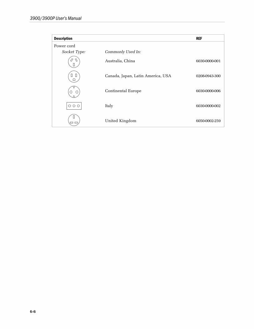
3900/3900P User’s Manual
6-6
Description REF
Power cordSocket Type: Commonly Used In:
Australia, China
Canada, Japan, Latin America, USA
Continental Europe
Italy
United Kingdom
6030-0000-001
0208-0943-300
6030-0000-006
6030-0000-002
6050-0002-259

7-1
7/Compliance and SpecificationsThis chapter contains
• Information about the tests that were conducted and the regulations withwhich the oximeter complies to assure its safe use.
• Performance specifications for the oximeter.
Compliance with standardsThe presence on the monitor of any symbol described below indicatescompliance with the standard represented by that symbol.
0537
Medical Device Directive 93/42/EEC of the European Union for aclass I (with a measuring function), IIa, IIb, or III device.
Medical electrical equipment classified in the US and Canadawith respect to electric shock, fire, and mechanical hazards only,in accordance with the Canadian Standards AssociationCAN/CSA C22.2 No. 601.1 and Underwriters Laboratories Inc.UL 2601-1.
General safety requirementsThe 3900 and 3900P comply with the requirements of EN 60601-1 Part 1: Generalrequirements for safety of medical electrical equipment.
Type BF applied part.
Type of protection against electric shock: Class I/Internal electrical power source
Degree of protection against ingress of liquids: Ordinary (IPX0)
Mode of operation: Continuous
The monitor also complies with the following:
EN 865 Pulse oximeters – Particular requirements
EN 475 Medical devices – Electrically-generated alarm signals
3900/3900P User’s Manual
7-2
Electromagnetic compatibility (EMC)The 3900 and 3900P pulse oximeters comply with the requirements of EN 60601-1-2: Electromagnetic compatibility – Requirements and tests.
Emissions EN 55011 Group I, Class B
The 3900 and 3900P pulse oximeters were tested with an RS-232 cable and analogoutput cables attached when operating on AC power. A USRobotics Sportster faxmodem was connected during Electrical Safety and EMC testing. The analogoutput was measured using a fiber optic link during testing. The oximeters weretested with no peripheral devices when operating on battery power.
When installing and using this monitor, take precautions to ensure electromagneticcompatibility. For more information, refer to the 3800/3900/3900P TechnicalReference Manual.
Electromagnetic effectsElectromagnetic interference, including interference from portable and mobileradio frequency (RF) communications equipment, can affect this monitor.Indications that the 3900 or 3900P is experiencing electromagnetic interferenceinclude the following:
• Variations in the PerfTrak waveform display.
• Sudden increases or decreases in the waveform height that do not correlate tothe physiological condition of the patient.
• Sensor-related messages that are not resolved by the instructions found in thismanual.
• The display of dashes on numeric LEDs when a valid physiological signal ispresent.
• Printed output that is garbled, solid black, or missing.
This interference may be intermittent and careful correlation between the effectand its possible source is important. Indications of interference should not occur ifthe monitor is used within its intended electromagnetic environment.
Safety checks for softwareThe Datex-Ohmeda software design controls include performance of a riskanalysis using methods consistent with EN 1441 Medical devices – Risk analysis.
To ensure proper operation of the 3900/3900P software, the 3900/3900P employsthree separate watchdog circuits for the microprocessors, power-on self-tests(including memory checksum and calibration verification), and memory testsduring monitoring. The software continuously monitors the patient sensor and, if afailure is detected, discontinues power to the sensor.
7/Compliance and Specifications
7-3
SpecificationsUnless otherwise indicated, all specifications are nominal and are subject tochange without notice.
CircuitryMicroprocessor-controlled
Automatic self-test of oximeter when powered on
Automatic setting of default parameters
Automatic alarm messages
Trend (real-time and stored) data output of SpO2, pulse rate, PIr pulsatile value,and alarm messages to the built-in printer (3900P only), and through theRS-232 serial port—up to 24 hours of stored data
SpO2 and pulse rate output through two analog channels
Audio indicatorsAdjustable-volume audible pulse
Adjustable-volume audible alarm tone
Pitch modulation reflects changing SpO2 levels
Alarm silence (120 seconds)
All mute (continuous silence)
Pulse rate out-of-limits alarm
SpO2 level out-of-limits alarm
Sensor-condition alarms
System-failure and recharge-battery alarms
Audible alarmsSetting levels available:
Alarm: 1 through 5Pulse beep: OFF and 1 through 5
Intensity at 1-meter distance:Volume setting of 1: 55 decibels (minimum)Volume setting of 5: 85 decibels (maximum)
Alarm limitsSpO2 alarm limit range:
High = 50 to 100% or OFFLow = OFF or 50 to 100%
Pulse rate alarm limit range in beats per minute (BPM):High = 30 to 235 or OFFLow = OFF or 30 to 235
3900/3900P User’s Manual
7-4
DisplaysThe displayed SpO2, pulse rate, and PIr values are updated every second. Theplethysmographic waveform sweep is updated every 4 seconds.
Numeric display (Light-Emitting Diodes–LEDs)Arterial oxygen saturation (SpO2) reading
Pulse-rate reading
Graphic display (Liquid Crystal Display–LCD)Plethysmographic waveform
SpO2 real-time or stored data graph
PIr pulsatile value real-time or stored data graph
PIr pulsatile value
High and low SpO2 alarm limits settings
High and low pulse rate alarm limits settings
Sensor condition alarms
System operational status messages
Alarm messages
Contrast adjustment for best viewing
Mode switchLanguage: Danish, Dutch, English (factory setting), Finnish, French, German,
Italian, Japanese, Norwegian, Polish, Portuguese, Spanish, or Swedish
Averaging mode: Long / TruTrak+ (12 seconds–factory setting),Medium (6 seconds), or Short (3 seconds)
PIr pulsatile value display: Yes (factory setting) or No
EMI line frequency: 60 Hz (factory setting) or 50 Hz
SpO2
Range: 0 to 100%
Accuracy, Arms (previously represented by 1 Standard Deviation):70 to 100% ± 2 digits70 to 100% ± 3 digits during conditions of clinical patient motion (withTruTrak+ enabled)Below 70% unspecified
Resolution: 1%
Interfering substancesCarboxyhemoglobin may erroneously increase readings. The level of increase isapproximately equal to the amount of carboxyhemoglobin present. Dyes, or anysubstances containing dyes, that change usual arterial pigmentation may causeerroneous readings.
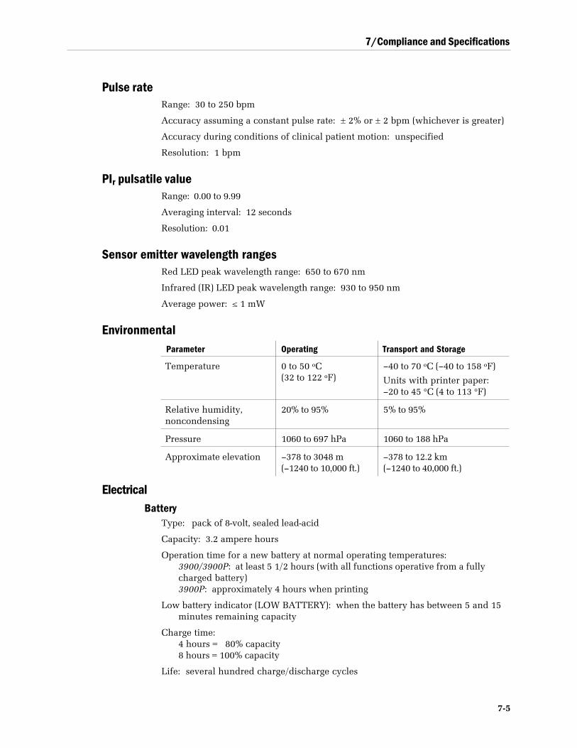
7/Compliance and Specifications
7-5
Pulse rateRange: 30 to 250 bpm
Accuracy assuming a constant pulse rate: ± 2% or ± 2 bpm (whichever is greater)
Accuracy during conditions of clinical patient motion: unspecified
Resolution: 1 bpm
PIr pulsatile valueRange: 0.00 to 9.99
Averaging interval: 12 seconds
Resolution: 0.01
Sensor emitter wavelength rangesRed LED peak wavelength range: 650 to 670 nm
Infrared (IR) LED peak wavelength range: 930 to 950 nm
Average power: ≤ 1 mW
EnvironmentalParameter Operating Transport and Storage
Temperature 0 to 50 ºC(32 to 122 ºF)
–40 to 70 ºC (–40 to 158 ºF)
Units with printer paper:–20 to 45 °C (4 to 113 °F)
Relative humidity,noncondensing
20% to 95% 5% to 95%
Pressure 1060 to 697 hPa 1060 to 188 hPa
Approximate elevation –378 to 3048 m(–1240 to 10,000 ft.)
–378 to 12.2 km(–1240 to 40,000 ft.)
ElectricalBattery
Type: pack of 8-volt, sealed lead-acid
Capacity: 3.2 ampere hours
Operation time for a new battery at normal operating temperatures:3900/3900P: at least 5 1/2 hours (with all functions operative from a fullycharged battery)3900P: approximately 4 hours when printing
Low battery indicator (LOW BATTERY): when the battery has between 5 and 15minutes remaining capacity
Charge time:4 hours = 80% capacity8 hours = 100% capacity
Life: several hundred charge/discharge cycles
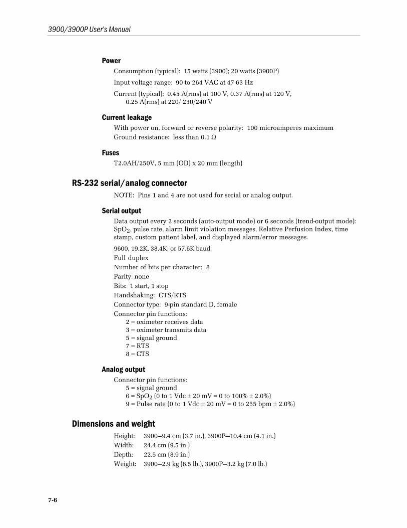
3900/3900P User’s Manual
7-6
PowerConsumption (typical): 15 watts (3900); 20 watts (3900P)
Input voltage range: 90 to 264 VAC at 47-63 Hz
Current (typical): 0.45 A(rms) at 100 V, 0.37 A(rms) at 120 V,0.25 A(rms) at 220/ 230/240 V
Current leakageWith power on, forward or reverse polarity: 100 microamperes maximumGround resistance: less than 0.1 Ω
FusesT2.0AH/250V, 5 mm (OD) x 20 mm (length)
RS-232 serial/analog connectorNOTE: Pins 1 and 4 are not used for serial or analog output.
Serial outputData output every 2 seconds (auto-output mode) or 6 seconds (trend-output mode):SpO2, pulse rate, alarm limit violation messages, Relative Perfusion Index, timestamp, custom patient label, and displayed alarm/error messages.
9600, 19.2K, 38.4K, or 57.6K baudFull duplexNumber of bits per character: 8Parity: noneBits: 1 start, 1 stopHandshaking: CTS/RTSConnector type: 9-pin standard D, femaleConnector pin functions:
2 = oximeter receives data3 = oximeter transmits data5 = signal ground7 = RTS8 = CTS
Analog outputConnector pin functions:
5 = signal ground6 = SpO2 (0 to 1 Vdc ± 20 mV = 0 to 100% ± 2.0%)9 = Pulse rate (0 to 1 Vdc ± 20 mV = 0 to 255 bpm ± 2.0%)
Dimensions and weightHeight: 3900—9.4 cm (3.7 in.), 3900P—10.4 cm (4.1 in.)Width: 24.4 cm (9.5 in.)Depth: 22.5 cm (8.9 in.)Weight: 3900—2.9 kg (6.5 lb.), 3900P—3.2 kg (7.0 lb.)
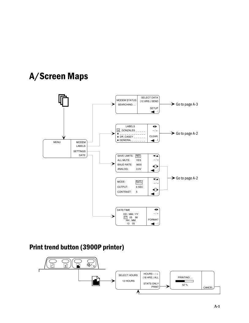
Σ
MENU
DATE
MODEM
LABELS
SETTINGS
MODEM STATUS:SELECT DATA
(12 HRS.) SEND
SETUP
SEARCHING …
LABELS
– / +
CLEAR
– / +
SAVE LIMITS: NO
ALL MUTE: YES
BAUD RATE: 9600
ANALOG: 0.0V
DATE/TIME
DD / MM / YY17 05 98
HH : MM13 05
FORMAT
– / +
Go to page A-2
Go to page A-2
Go to page A-3
A/Screen Maps
A-1
– / +MODE: SpO2
OUTPUT: 6 SEC
CONTRAST: 5
Print trend button (3900P printer)
SELECT HOURS
12 HOURS
HOURS – / +
(18 HRS.) ALL
STATS ONLYPRINT CANCEL
PRINTING …
H _ GONZALES _ _ _ _ _ _ _ _ _ _ _ _ _ _ _ _ _DR_CASEY _ _ _ _ _ _ GENERAL _ _ _ _ _ _ _
ooo
52 %
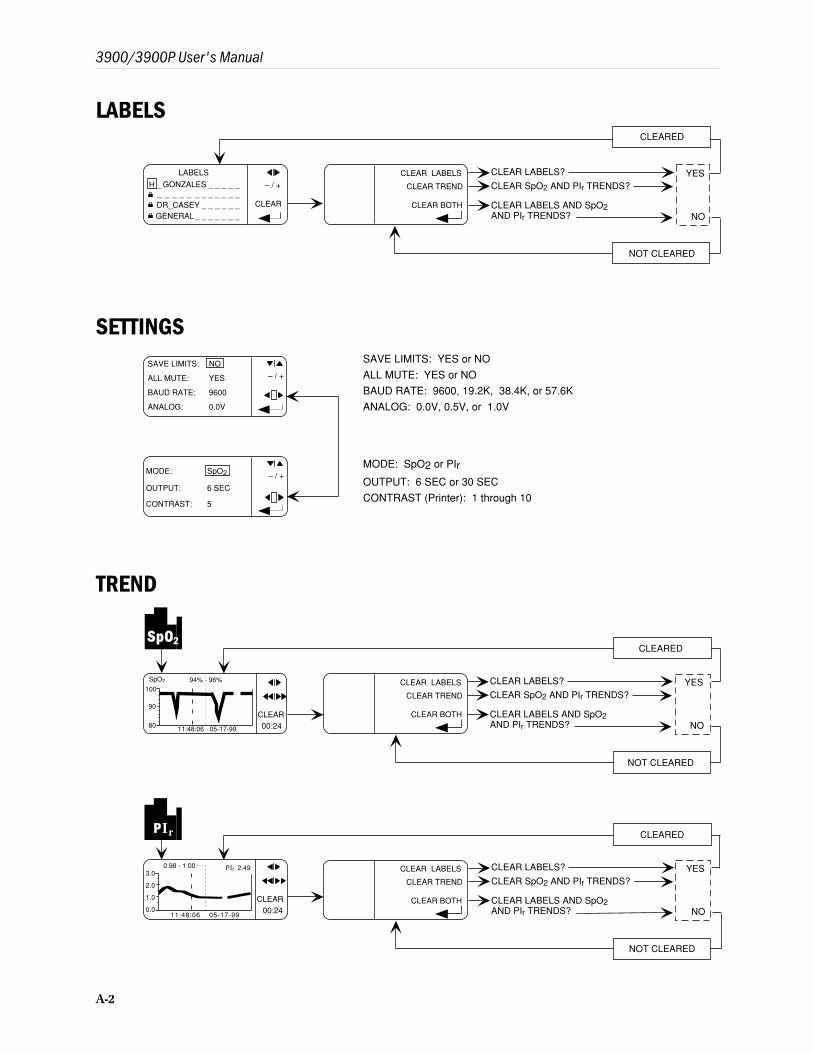
LABELS
– / +
CLEAR
CLEAR LABELS? YES
NO
LABELS
CLEAR LABELS
CLEAR TREND
CLEAR BOTH
CLEAR SpO2 AND PIr TRENDS?
CLEAR LABELS AND SpO2AND PIr TRENDS?
CLEARED
NOT CLEARED
SETTINGS
– / +
SAVE LIMITS: NO
ALL MUTE: YES
BAUD RATE: 9600
ANALOG: 0.0V
SAVE LIMITS: YES or NO
ALL MUTE: YES or NO
BAUD RATE: 9600, 19.2K, 38.4K, or 57.6K
ANALOG: 0.0V, 0.5V, or 1.0V
MODE: SpO2 or PIr
OUTPUT: 6 SEC or 30 SEC
CONTRAST (Printer): 1 through 10
– / +MODE: SpO2
OUTPUT: 6 SEC
CONTRAST: 5
A-2
3900/3900P User's Manual
TREND
CLEAR00:24
P Ir 2.490.98 - 1.003.0
11:48:06 05-17-990.0
2.0
1.0
CLEAR00:24
SpO2 94% - 96%100
11:48:06 05-17-99
90
80
SSppOO2
CLEAR LABELS
CLEAR TREND
CLEAR BOTH
PP Ir
H _ GONZALES _ _ _ _ _ _ _ _ _ _ _ _ _ _ _ _ _DR_CASEY _ _ _ _ _ _ GENERAL _ _ _ _ _ _ _
ooo
CLEAR LABELS
CLEAR TREND
CLEAR BOTH
CLEAR LABELS? YES
NO
CLEAR SpO2 AND PIr TRENDS?
CLEAR LABELS AND SpO2AND PIr TRENDS?
CLEARED
NOT CLEARED
CLEAR LABELS? YES
NO
CLEAR SpO2 AND PIr TRENDS?
CLEAR LABELS AND SpO2AND PIr TRENDS?
CLEARED
NOT CLEARED
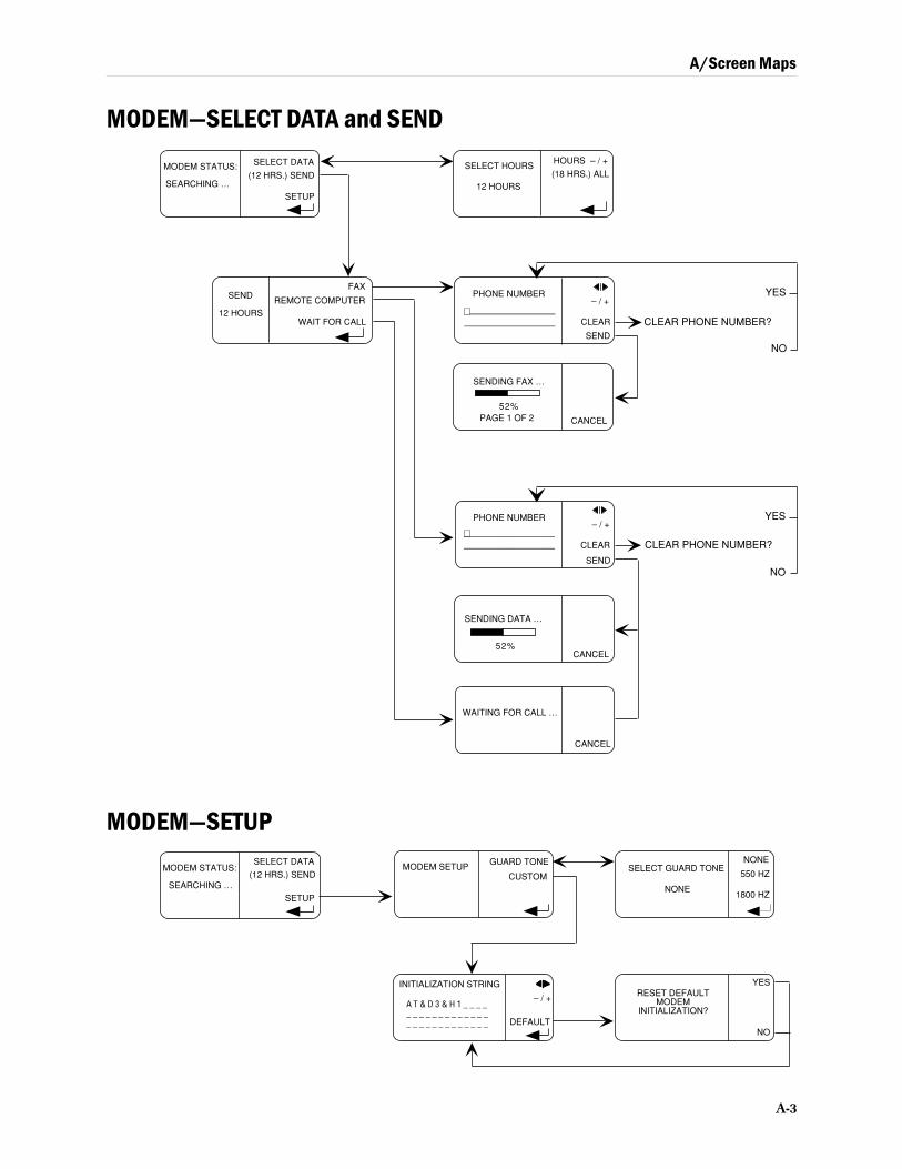
A/Screen Maps
A-3
MODEM—SELECT DATA and SEND
WAITING FOR CALL …
CANCEL
SENDING DATA …
CANCEL
SEND
12 HOURS
FAX
REMOTE COMPUTER
WAIT FOR CALL––––––––––––––––––––
–––––––––––––––––––– SEND
PHONE NUMBER– / +
CLEAR CLEAR PHONE NUMBER?
YES
NO
SENDING FAX …
PAGE 1 OF 2 CANCEL
52%
SEND
PHONE NUMBER– / +
CLEAR––––––––––––––––––––
––––––––––––––––––––
SELECT HOURS
12 HOURS
HOURS – / +
(18 HRS.) ALLMODEM STATUS:
(12 HRS.) SEND
SETUPSEARCHING …
SELECT DATA
YES
NO
CLEAR PHONE NUMBER?
SELECT GUARD TONENONE
550 HZ
1800 HZNONE
RESET DEFAULTMODEM
INITIALIZATION?
YES
NO
MODEM SETUPGUARD TONE
CUSTOMMODEM STATUS:
(12 HRS.) SEND
SETUP
SEARCHING …
MODEM—SETUPSELECT DATA
– / +
DEFAULT
INITIALIZATION STRING
A T & D 3 & H 1 _ _ _ __ _ _ _ _ _ _ _ _ _ _ _ __ _ _ _ _ _ _ _ _ _ _ _ _
52%

A-4
3900/3900P User's Manual
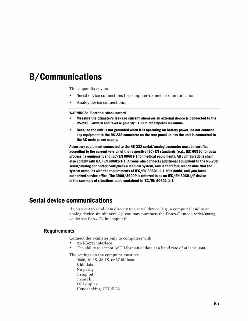
B-1
B/CommunicationsThis appendix covers
• Serial device connections for computer/oximeter communication.
• Analog device connections.
WARNINGS: Electrical shock hazard• Measure the oximeter’s leakage current whenever an external device is connected to the
RS-232. Forward and reverse polarity: 100 microamperes maximum.
• Because the unit is not grounded when it is operating on battery power, do not connectany equipment to the RS-232 connector on the rear panel unless the unit is connected tothe AC main power supply.
Accessory equipment connected to the RS-232 serial/analog connector must be certifiedaccording to the current version of the respective IEC/EN standards (e.g., IEC 60950 for dataprocessing equipment and IEC/EN 60601-1 for medical equipment). All configurations shallalso comply with IEC/EN 60601-1-1. Anyone who connects additional equipment to the RS-232serial/analog connector configures a medical system, and is therefore responsible that thesystem complies with the requirements of IEC/EN 60601-1-1. If in doubt, call your localauthorized service office. The 3900/3900P is referred to as an IEC/EN 60601/F device in the summary of situations table contained in IEC/EN 60601-1-1.
Serial device communicationsIf you want to send data directly to a serial device (e.g., a computer) and to ananalog device simultaneously, you may purchase the Datex-Ohmeda serial/analogcable; see Parts list in chapter 6.
RequirementsConnect the oximeter only to computers with• An RS-232 interface.• The ability to accept ASCII-formatted data at a baud rate of at least 9600.
The settings on the computer must be:9600, 19.2K, 38.4K, or 57.6K baud8-bit dataNo parity1 stop bit1 start bitFull duplexHandshaking, CTS/RTS
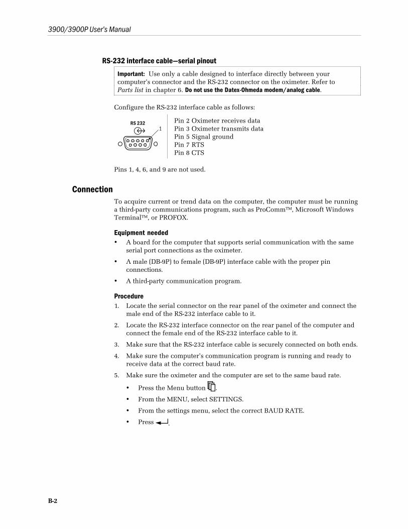
3900/3900P User’s Manual
B-2
RS-232 interface cable—serial pinout
Important: Use only a cable designed to interface directly between yourcomputer’s connector and the RS-232 connector on the oximeter. Refer toParts list in chapter 6. Do not use the Datex-Ohmeda modem/analog cable.
Configure the RS-232 interface cable as follows:
RS 2321
Pin 2 Oximeter receives dataPin 3 Oximeter transmits dataPin 5 Signal groundPin 7 RTSPin 8 CTS
Pins 1, 4, 6, and 9 are not used.
ConnectionTo acquire current or trend data on the computer, the computer must be runninga third-party communications program, such as ProComm™, Microsoft WindowsTerminal™, or PROFOX.
Equipment needed• A board for the computer that supports serial communication with the same
serial port connections as the oximeter.
• A male (DB-9P) to female (DB-9P) interface cable with the proper pinconnections.
• A third-party communication program.
Procedure1. Locate the serial connector on the rear panel of the oximeter and connect the
male end of the RS-232 interface cable to it.
2. Locate the RS-232 interface connector on the rear panel of the computer andconnect the female end of the RS-232 interface cable to it.
3. Make sure that the RS-232 interface cable is securely connected on both ends.
4. Make sure the computer’s communication program is running and ready toreceive data at the correct baud rate.
5. Make sure the oximeter and the computer are set to the same baud rate.
• Press the Menu button .
• From the MENU, select SETTINGS.
• From the settings menu, select the correct BAUD RATE.
• Press .
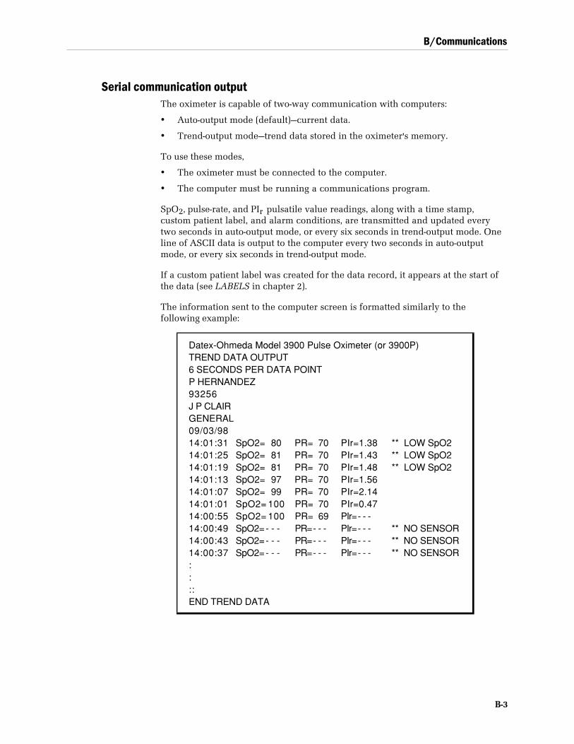
B/Communications
B-3
Serial communication outputThe oximeter is capable of two-way communication with computers:
• Auto-output mode (default)—current data.
• Trend-output mode—trend data stored in the oximeter's memory.
To use these modes,
• The oximeter must be connected to the computer.
• The computer must be running a communications program.
SpO2, pulse-rate, and PIr pulsatile value readings, along with a time stamp,custom patient label, and alarm conditions, are transmitted and updated everytwo seconds in auto-output mode, or every six seconds in trend-output mode. Oneline of ASCII data is output to the computer every two seconds in auto-outputmode, or every six seconds in trend-output mode.
If a custom patient label was created for the data record, it appears at the start ofthe data (see LABELS in chapter 2).
The information sent to the computer screen is formatted similarly to thefollowing example:
Datex-Ohmeda Model 3900 Pulse Oximeter (or 3900P)TREND DATA OUTPUT6 SECONDS PER DATA POINTP HERNANDEZ93256J P CLAIRGENERAL09/03/9814:01:31 SpO2= 80 PR= 70 PIr=1.38 ** LOW SpO214:01:25 SpO2= 81 PR= 70 PIr=1.43 ** LOW SpO214:01:19 SpO2= 81 PR= 70 PIr=1.48 ** LOW SpO214:01:13 SpO2= 97 PR= 70 PIr=1.5614:01:07 SpO2= 99 PR= 70 PIr=2.1414:01:01 SpO2= 100 PR= 70 PIr=0.4714:00:55 SpO2= 100 PR= 69 PIr= - - -14:00:49 SpO2= - - - PR= - - - PIr= - - - ** NO SENSOR14:00:43 SpO2= - - - PR= - - - PIr= - - - ** NO SENSOR14:00:37 SpO2= - - - PR= - - - PIr= - - - ** NO SENSOR::::END TREND DATA
3900/3900P User’s Manual
B-4
Auto-output modeThis is the default mode, which transmits monitoring data being currentlycollected. It is present when the oximeter begins communication with a computer,and is the mode the oximeter returns to when exiting from other modes.
Messages relating to SpO2, pulse rate, PIr , and alarm limits violations that appearon the oximeter also appear on the computer.
Trend-output modeThis mode allows up to 24 hours of trend data to be output to a computer.
NOTE: 24 hours of trend data are output in 10 minutes or less, depending on thebaud rate.
To enter trend-output mode:Enter: <esc> CJ <enter>
To exit trend-output mode while trend data are being output:Enter: <esc> CK <enter>
After trend data are output, auto-output mode automatically resumes. Trend dataare still in memory and can be output again without turning the oximeter off andon again.
NOTE: No other modes can be activated through the computer interface while intrend-output mode; only the trend output exit command is recognized.
To clear-trend data in the oximeter’s memory using the computer:Enter: <esc> CP <enter>
Analog device communicationsCAUTION: To prevent improper loading, which upsets the correspondence between the measuredvoltage and the intended output voltage, connect only a high impedance device (1K Ω or higher) tothe analog output.
The 3900/3900P oximeter interfaces with any analog recording device capable ofaccepting the 0- to 1-volt signal outputs that represent the SpO2 and pulse ratevalues.
If you want to send data directly to a serial device (e.g., a computer) and to ananalog device simultaneously, you may purchase the Datex-Ohmeda serial/analogcable; see Parts list in chapter 6.
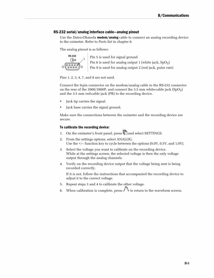
B/Communications
B-5
RS-232 serial/analog interface cable—analog pinoutUse the Datex-Ohmeda modem/analog cable to connect an analog recording deviceto the oximeter. Refer to Parts list in chapter 6.
The analog pinout is as follows:
RS 2321 Pin 5 is used for signal ground
Pin 6 is used for analog output 1 (white jack, SpO2)
Pin 9 is used for analog output 2 (red jack, pulse rate)
Pins 1, 2, 3, 4, 7, and 8 are not used.
Connect the 9-pin connector on the modem/analog cable to the RS-232 connectoron the rear of the 3900/3900P, and connect the 3.5 mm white-cable jack (SpO2)and the 3.5 mm red-cable jack (PR) to the recording device.
• Jack tip carries the signal.
• Jack base carries the signal ground.
Make sure the connections between the oximeter and the recording device aresecure.
To calibrate the recording device:
1. On the oximeter’s front panel, press and select SETTINGS.
2. From the settings options, select ANALOG.Use the +/– function key to cycle between the options (0.0V, 0.5V, and 1.0V).
3. Select the voltage you want to calibrate on the recording device.While at the settings screen, the selected voltage is then the only voltageoutput through the analog channels.
4. Verify on the recording device output that the voltage being sent is beingrecorded correctly.
If it is not, follow the instructions that accompanied the recording device toadjust it to the correct voltage.
5. Repeat steps 3 and 4 to calibrate the other voltage.
6. When calibration is complete, press to return to the waveform screen.

3900/3900P User’s Manual
B-6

Index
Aanalog communications, B-4
analog interface cable, B-5alarms
alarm limits display, 1-8alarm silence button, 1-7all mute, 1-7, 2-16high priority, 3-5low priority, 3-6medium priority, 3-5message categories, 3-5messages, 3-1save limits, 2-15set pulse rate limits, 1-9set SpO2 limits, 1-9specifications, 7-3SpO 2 limits below 80%, 2-6system failure, 3-6volume, 1-11
audio indicators, specifications, 7-3
Bbattery
operation, 1-9status indicator, 1-10recharging, 6-2replacing, 6-2specifications, 7-5
Ccalibration, 1-5cancel transmission, modem, 5-7, 5-10cautions, 1-15checkout procedure, 2-5cleaning, 6-1communications, B-1
analog devices, B-4serial devices, B-1
connectorequipotential ground, 1-12power, 1-12serial and analog, 1-12SpO 2 sensor, 1-10
current leakage specifications, 7-6
Ddate, set format, 2-17display
contrast adjuster, 1-9graphic, 1-8numeric, 1-7, 2-10specifications, 7-4
Eelectromagnetic compatibility (EMC), 7-2
Ffax modem, 5-6fax modem status, 5-3features, 1-1, 1-2
functional components, 1-3PIr pulsatile value, 1-2TruTrak+ technology, 1-1
front panel, 1-6fuses, 1-12
replacing, 6-3specifications, 7-6
Gguard tone, modem, 5-11
Hhandle, carrying, 1-10
Iinitialization string, modem
custom, 5-11default, 5-12
InstaReport fax, PIr mode, 5-16InstaReport fax, SpO2 mode, 5-14
Llabels, 2-12
clear, 2-14create, 2-13lock label lines, 2-14
locklabel lines, 2-14monitor buttons, 2-22
low perfusion, 2-8
Mmaintenance, 6-1maintenance, printer, 4-5menu
screen display button, 1-10messages, 3-1
display, 1-8fax transmission, 5-7modem transmission failure, 5-10
mode switch, 1-12specifications, 7-4
mode switch settings, 2-3averaging mode, SpO2 and pulse rate, 2-4EMI line frequency, 2-4language, 2-3PIr pulsatile value display, 2-4
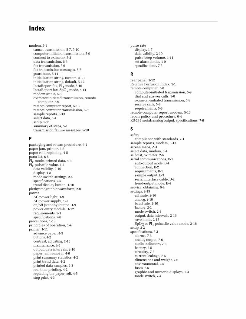
Index
modem, 5-1cancel transmission, 5-7, 5-10computer-initiated transmission, 5-9connect to oximeter, 5-2data transmission, 5-5fax transmission, 5-6fax transmission messages, 5-7guard tone, 5-11initialization string, custom, 5-11initialization string, default, 5-12InstaReport fax, PIr mode, 5-16InstaReport fax, SpO2 mode, 5-14modem status, 5-3oximeter-initiated transmission, remote
computer, 5-9remote computer report, 5-13remote computer transmission, 5-8sample reports, 5-13select data, 5-4setup, 5-11summary of steps, 5-1transmission failure messages, 5-10
Ppackaging and return procedure, 6-4paper jam, printer, 4-6paper roll, replacing, 4-5parts list, 6-5PIr mode, printed data, 4-3PIr pulsatile value, 1-2
data validity, 2-10display, 1-8mode switch settings, 2-4specifications, 7-5trend display button, 1-10
plethysmographic waveform, 2-8power
AC power light, 1-9AC power supply, 1-9on/off (standby) button, 1-9power entry module, 1-12requirements, 2-1specifications, 7-6
precautions, 1-13principles of operation, 1-4printer, 1-11
advance paper, 4-3buttons, 4-2contrast, adjusting, 2-16maintenance, 4-5output, data intervals, 2-16paper jam removal, 4-6print summary statistics, 4-2print trend data, 4-2printed data samples, 4-3real-time printing, 4-2replacing the paper roll, 4-5stop print, 4-3
pulse ratedisplay, 1-7data validity, 2-10pulse beep volume, 1-11set alarm limits, 1-9specifications, 7-5
Rrear panel, 1-12Relative Perfusion Index, 1-1remote computer, 5-8
computer-initiated transmission, 5-9dial and answer calls, 5-8oximeter-initiated transmission, 5-9receive calls, 5-8requirements, 5-8
remote computer report, modem, 5-13repair policy and procedure, 6-4RS-232 serial/analog output, specifications, 7-6
Ssafety
compliance with standards, 7-1sample reports, modem, 5-13screen maps, A-1select data, modem, 5-4self-test, oximeter, 2-6serial communications, B-1
auto-output mode, B-4connection, B-2requirements, B-1sample output, B-3serial interface cable, B-2trend-output mode, B-4
service, obtaining, 6-4settings, 2-15
all mute, 2-16analog, 2-16baud rate, 2-16factory, 2-2mode switch, 2-3output, data intervals, 2-16save limits, 2-15SpO2 or PIr pulsatile value mode, 2-16
setup, 2-2specifications, 7-3
alarms, 7-3analog output, 7-6audio indicators, 7-3battery, 7-5circuitry, 7-3current leakage, 7-6dimensions and weight, 7-6environmental, 7-5fuses, 7-6graphic and numeric displays, 7-4mode switch, 7-4
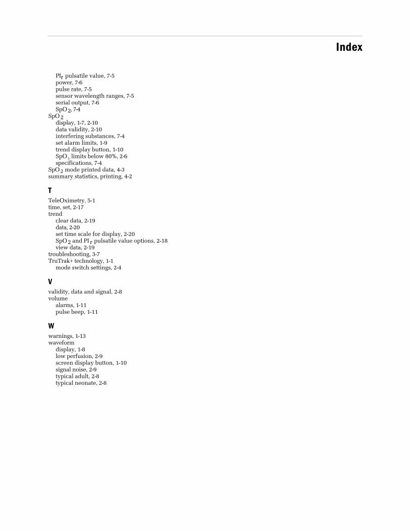
Index
PIr pulsatile value, 7-5power, 7-6pulse rate, 7-5sensor wavelength ranges, 7-5serial output, 7-6SpO2, 7-4
SpO2display, 1-7, 2-10data validity, 2-10interfering substances, 7-4set alarm limits, 1-9trend display button, 1-10SpO 2 limits below 80%, 2-6specifications, 7-4
SpO2 mode printed data, 4-3summary statistics, printing, 4-2
TTeleOximetry, 5-1time, set, 2-17trend
clear data, 2-19data, 2-20set time scale for display, 2-20SpO2 and PIr pulsatile value options, 2-18view data, 2-19
troubleshooting, 3-7TruTrak+ technology, 1-1
mode switch settings, 2-4
Vvalidity, data and signal, 2-8volume
alarms, 1-11pulse beep, 1-11
Wwarnings, 1-13waveform
display, 1-8low perfusion, 2-9screen display button, 1-10signal noise, 2-9typical adult, 2-8typical neonate, 2-8

Index

Warranty
The 3900 and 3900P Pulse oximeters are sold by GE Healthcare only under the warranties set forthin the following paragraphs. Such warranties are extended only with respect to the purchase ofthese products directly from GE Healthcare Authorized Dealers as new merchandise and areextended to the first Buyer thereof, other than for resale.
Limited warrantyGE Healthcare warrants that the 3900 and 3900P Pulse Oximeters meet their publishedspecifications at the time of shipment from the factory.
Products not under warrantyThe following items are not covered under this warranty: disposable items, accessories, servicekits, and replacement parts. These items may be covered under a separate warranty. Consult GEHealthcare for details.
DurationThe 3900 and 3900P Pulse Oximeters are warranted against defect in materials and workmanshipfor a period of three (3) years from the date of delivery to the user (in no event for a period of morethan four [4] years from the date of original delivery by GE Healthcare to an Authorized Dealer).The battery is warranted against defects in materials and workmanship for one (1) year from thedate of delivery to the user.
If any part of this product proves defective under proper and normal use within the warrantyperiod, as the purchaser's exclusive remedy, GE Healthcare will repair or replace, at its solediscretion, the product or any defective part provided it is returned to GE Healthcare Servicewithin 30 days of the failure.
LimitationGE Healthcare may at any time discharge its warranty obligation by repairing and returning the3900 or 3900P Pulse Oximeter to original factory performance. This may be accomplished byinstalling new or remanufactured assemblies or by other repairs deemed appropriate by GEHealthcare. The choice of repair or replacement by GE Healthcare shall be the sole remedy of thebuyer or user.
ConditionsThis warranty is valid only when qualified personnel trained in the repair of the 3900 or 3900PPulse Oximeter have performed installation and service on this equipment and when allrecommended planned maintenance procedures have been completed during the warrantyperiod. Damage caused by the abuse or misuse of the 3900 or 3900P Pulse Oximeter is not coveredby this warranty. GE Healthcare shall not be liable for damage resulting from the improperinstallation or the misuse of the 3900 or 3900P Pulse Oximeter.
Exclusion of warrantiesOral statements about the 3900 or 3900P Pulse Oximeter do not constitute warranties, shall not berelied on by the buyer or user, and are not part of any warranty extended by GE Healthcare.
Except as set forth in this limited warranty, GE Healthcare makes no warranties, expressed orimplied, including the implied warranty of merchantability and the implied warranty of fitnessfor a particular purpose. Except for the obligations under this limited warranty, GE Healthcareshall not have any obligation or liability for any incidental or consequential damages (includingthose from commercial loss) or other loss, damage, or injury resulting directly or indirectly fromthe 3900 or 3900P Pulse Oximeter.