3900 GC Operation Manual - LabXphotos.labwrench.com/equipmentManuals/10682-6147.pdf · the lab, the...
77
Varian Analytical Instruments 2700 Mitchell Drive Walnut Creek, CA 94598-1675/US ©Varian, Inc. 2002 03-914911-00:Rev. 3 3900 GC Operation Manual
Transcript of 3900 GC Operation Manual - LabXphotos.labwrench.com/equipmentManuals/10682-6147.pdf · the lab, the...

Varian Analytical Instruments 2700 Mitchell Drive Walnut Creek, CA 94598-1675/US
©Varian, Inc. 2002 03-914911-00:Rev. 3
3900 GC Operation Manual

Read Before Operating Important Safeguards
CAUTION The following items are frequently not recognized or are overlooked by new users while learning to operate a GC or a GC/MS. They are brought to your attention to safeguard against damage to your equipment.
Carrier gas must be flowing through the column before heating the column oven. Carefully evaluate columns that have been heated with no carrier gas flowing through and discard, if damaged. Ensure the injector contains a septum and there is a positive flow of carrier gas before heating the column.
The column outlet in a GC/MS system is at a vacuum. Do not use columns which are wide bore and short in length with constant flow at low flow rates (1.5 mL/min or less) since the inlet pressure may be less than the ambient 1 atmosphere. An inlet pressure less than ambient will be indicated as a negative pressure. If the required pressure is less than 1 atmosphere, the system will try to adjust the pressure to the calculated value. Since the split vent and septum purge valve vent to the lab, the vacuum pump will draw air through your column potentially ruining the column and damaging your MS detector if installed.
Important Tips Regarding 3900 GC Operation After editing the active method, it must be re-activated before running the next analysis. Always remember to activate a method after you have made edits, if you intend to run that method next.
Note that the 3900 GC without a keypad is controlled entirely from either the Star or Saturn Workstation. The 3900 GC without a keypad supports one active method at a time. You may build and edit methods at the Workstation on these GCs while the GC is running but you may not change the method that is currently running. If you are using the keypad version, you may only edit methods locally when the GC is not in the RUN state (executing a method).
The Status and Control screen for the 3900 GC has an extend runtime key that will allow you to extend the runtime by 10 minutes each time you click on the key. The extended run time will be used until the method is either re-activated or a new method is activated. The extend run feature does not change the method stored in your Workstation.
If a potentially hazardous fault is detected, such as a thermal runaway, the 3900 GC shuts down the affected component and reports the fault. After correcting the fault, normal operation is restored by powering the 3900 GC OFF then ON.
3900 GC Operation Manual 1
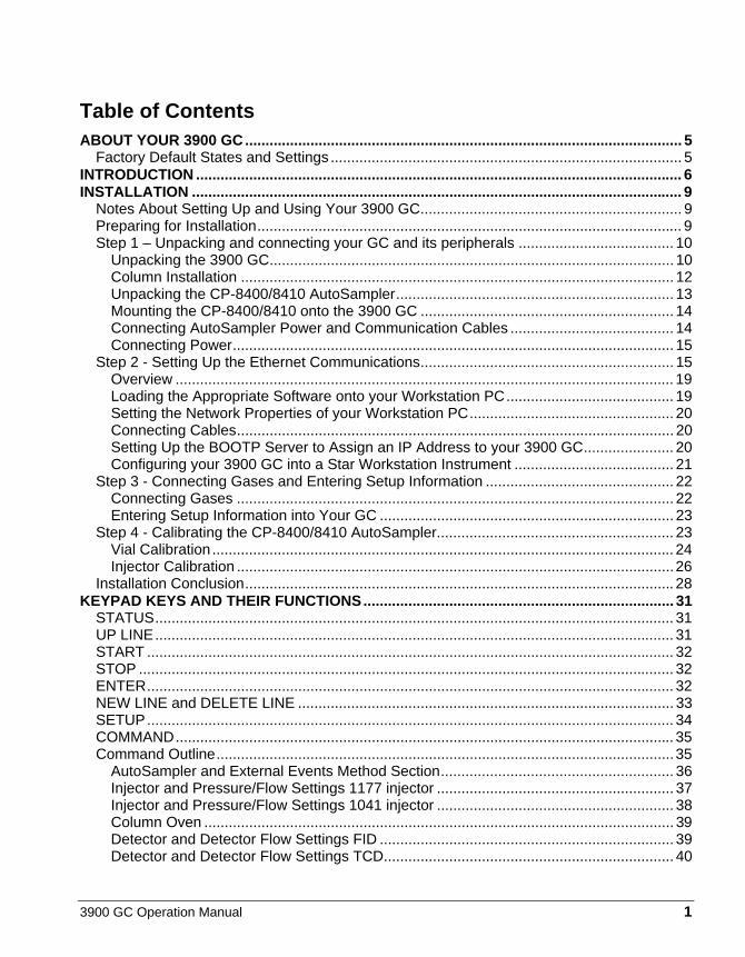
Table of Contents ABOUT YOUR 3900 GC........................................................................................................... 5
Factory Default States and Settings ...................................................................................... 5 INTRODUCTION ....................................................................................................................... 6 INSTALLATION ........................................................................................................................ 9
Notes About Setting Up and Using Your 3900 GC................................................................ 9 Preparing for Installation........................................................................................................ 9 Step 1 – Unpacking and connecting your GC and its peripherals ...................................... 10
Unpacking the 3900 GC................................................................................................... 10 Column Installation .......................................................................................................... 12 Unpacking the CP-8400/8410 AutoSampler.................................................................... 13 Mounting the CP-8400/8410 onto the 3900 GC .............................................................. 14 Connecting AutoSampler Power and Communication Cables ........................................ 14 Connecting Power............................................................................................................ 15
Step 2 - Setting Up the Ethernet Communications.............................................................. 15 Overview .......................................................................................................................... 19 Loading the Appropriate Software onto your Workstation PC......................................... 19 Setting the Network Properties of your Workstation PC.................................................. 20 Connecting Cables........................................................................................................... 20 Setting Up the BOOTP Server to Assign an IP Address to your 3900 GC...................... 20 Configuring your 3900 GC into a Star Workstation Instrument ....................................... 21
Step 3 - Connecting Gases and Entering Setup Information .............................................. 22 Connecting Gases ........................................................................................................... 22 Entering Setup Information into Your GC ........................................................................ 23
Step 4 - Calibrating the CP-8400/8410 AutoSampler.......................................................... 23 Vial Calibration................................................................................................................. 24 Injector Calibration ...........................................................................................................26
Installation Conclusion......................................................................................................... 28 KEYPAD KEYS AND THEIR FUNCTIONS............................................................................ 31
STATUS............................................................................................................................... 31 UP LINE............................................................................................................................... 31 START ................................................................................................................................. 32 STOP ................................................................................................................................... 32 ENTER................................................................................................................................. 32 NEW LINE and DELETE LINE ............................................................................................ 33 SETUP................................................................................................................................. 34 COMMAND.......................................................................................................................... 35 Command Outline................................................................................................................35
AutoSampler and External Events Method Section......................................................... 36 Injector and Pressure/Flow Settings 1177 injector .......................................................... 37 Injector and Pressure/Flow Settings 1041 injector .......................................................... 38 Column Oven ................................................................................................................... 39 Detector and Detector Flow Settings FID ........................................................................ 39 Detector and Detector Flow Settings TCD....................................................................... 40

2 03-914911-00:Rev. 3
Automation Schedule .......................................................................................................40 Automation Outline ...........................................................................................................41
MAINTENANCE.......................................................................................................................42 General GC Maintenance ....................................................................................................42
Checking and Renewing Gas Supplies............................................................................43 Leak Checking..................................................................................................................43 Gas Filter Cartridge Replacement....................................................................................45
Injector Maintenance............................................................................................................45 Septum Replacement .......................................................................................................45 Insert Replacement ..........................................................................................................46
The 1041 On-Column Injector..............................................................................................51 Automatic Start Switch .....................................................................................................51 Injector Assembly and Insert ............................................................................................51 Column Installation ...........................................................................................................52 Testing the 1041 Injector ..................................................................................................56
Detector Connections and Hardware...................................................................................57 FID Connections...............................................................................................................57 FID Hardware ...................................................................................................................58
Thermal Conductivity Detector.............................................................................................62 Initial Set-Up .....................................................................................................................62 TCD Adjustments .............................................................................................................62 Operation..........................................................................................................................63 Adjust TCD Carrier Gas Flow Rates ................................................................................68
REPLACEMENT PARTS.........................................................................................................69 FAULTS ...................................................................................................................................71
3900 GC Operation Manual 3
Figures Figure 1 3900 GC Features...................................................................................................... 8 Figure 2 Connectors for Peripheral Equipment...................................................................... 11 Figure 3 CP-8400 on the 3900 GC Showing Screw Locations Under the Carrousel ............ 14 Figure 4 3900 GC Rear Panel Showing CP-8400 Cabling .................................................... 15 Figure 5 3900 GC Connected Directly to a Star Workstation PC .......................................... 16 Figure 6 Isolated Network....................................................................................................... 16 Figure 7 Company Network.................................................................................................... 17 Figure 8 Proper Ferrule Orientation ....................................................................................... 22 Figure 9 Tower Position Calibration for CP-8400 Vial 0 or CP-8410 Vial 1 ........................... 24 Figure 10 Correct Vial 0/Vial 1 Calibration ............................................................................. 25 Figure 11 Correct Syringe Sled/Injector Position ................................................................... 26 Figure 12 Correct Injector Calibration .................................................................................... 27 Figure 13 3900 GC Keypad.................................................................................................... 30 Figure 14 Table Operations with Local User Interface........................................................... 33 Figure 15 CP-1177 Injector – Cross-sectional View .............................................................. 47 Figure 16 1041 Universal Injector with Insert .......................................................................... 52 Figure 17 Column Ends........................................................................................................... 53 Figure 18 FID Cross-sectional View....................................................................................... 57 Figure 19 FID Exploded View................................................................................................. 58 Figure 20 FID Tower Top View............................................................................................... 61 Figure 21 TCD Sensitivity and Amplification ........................................................................... 66
Tables Table 1 Column Insertion Depths............................................................................................ 12 Table 2 General Tightening and Retightening for Common Ferrules ..................................... 13 Table 3 Maintenance Schedule............................................................................................... 42 Table 4 General Tightening and Retightening for Common Ferrules ..................................... 54 Table 5 Carrier Gas Flow Rates for 1041................................................................................ 56 Table 6 1041 Test Compounds ............................................................................................... 56

4 03-914911-00:Rev. 3

3900 GC Operation Manual 5
About Your 3900 GC
The 3900 GC is designed to be a simple to use and easy to maintain Gas Chromatograph. The 3900 is a single channel all electronic gas chromatograph. It may be equipped with either an 1177 split/splitless or a 1041 on-column injector and either an FID or a TCD detector. Optionally it may have liquid CO2 column oven cryogenics and an Ethernet communications option. Typically the only operator interactions with the GC are to turn on the GC, put vials into the AutoSampler carrousel, change the AutoSampler syringe when required, change the column when needed, and change the injector septum when needed.
Column dimensions, temperature limits, A/S position calibration and other configuration functions are entered through the 3900 keypad, methods can be built from the Star Workstation and downloaded either manually or as part of an automated SampleList or Sequence or they can be built from the keypad.
All electrical connections and carrier gas supply connections are made at the back of the 3900 GC.
Factory Default States and Settings • When the GC is turned on, all five methods will be set to conditions
appropriate for light hydrocarbon analyses such as the FID Test Mix.
• The column oven defaults to power ON and a set temperature of 80 °C. It will have a ramp that ends at 160 °C.
• When installed, components that use a heated zone are turned on in the active method and default to a set temperature of 140 °C for the injector and 200 °C for the detector.
6 03-914911-00:Rev. 3
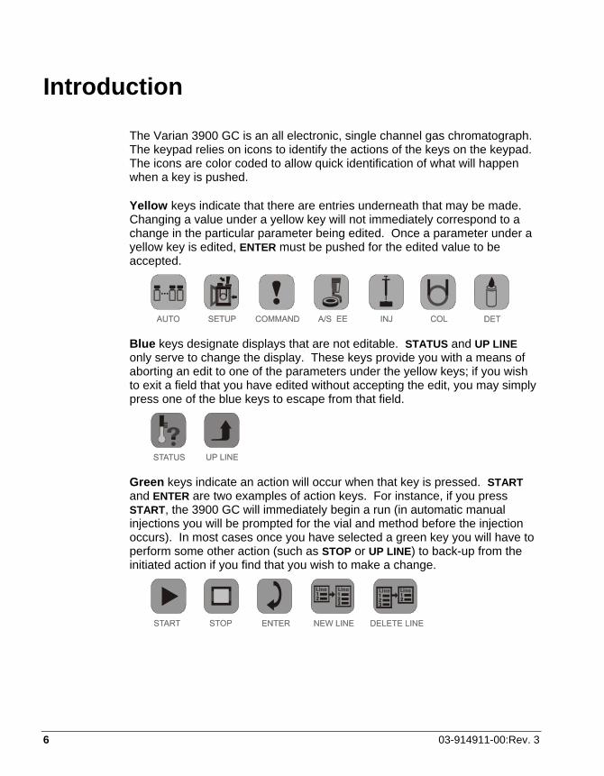
Introduction
The Varian 3900 GC is an all electronic, single channel gas chromatograph. The keypad relies on icons to identify the actions of the keys on the keypad. The icons are color coded to allow quick identification of what will happen when a key is pushed.
Yellow keys indicate that there are entries underneath that may be made. Changing a value under a yellow key will not immediately correspond to a change in the particular parameter being edited. Once a parameter under a yellow key is edited, ENTER must be pushed for the edited value to be accepted.
Blue keys designate displays that are not editable. STATUS and UP LINE only serve to change the display. These keys provide you with a means of aborting an edit to one of the parameters under the yellow keys; if you wish to exit a field that you have edited without accepting the edit, you may simply press one of the blue keys to escape from that field.
Green keys indicate an action will occur when that key is pressed. START and ENTER are two examples of action keys. For instance, if you press START, the 3900 GC will immediately begin a run (in automatic manual injections you will be prompted for the vial and method before the injection occurs). In most cases once you have selected a green key you will have to perform some other action (such as STOP or UP LINE) to back-up from the initiated action if you find that you wish to make a change.

3900 GC Operation Manual 7
All selections from the keypad are made via scrolling using the + and – keys immediately to the right of the display; it is not possible to enter an illegal value. To accept the value press ENTER immediately to the right of the + and – keys. You may press either ENTER or UP LINE to scroll between parameters.
The display is designed to show you both data and navigational information. This is presented to you in two ways;
1. An LED will illuminate showing you which section you are working in and displaying.
2. The display will provide you direct information on where in a section you are as well as the parameter.
In the following example, the A/S indicates you are working on the AutoSampler method section, the 2 represents the current line number, and the 31 indicates the total number of lines in the A/S User Defined section. The rest of the display is composed of the parameter and its current setting. An LED next to the A/S method section will be illuminated to further affirm that you are working in the A/S method section.
While not all displays will show current line out of a total number of lines, they all follow the principle of informing you which section you are in with an LED that indicates which key was selected.
The information above represents all of the fundamental interactions with the keypad.
If you are controlling your 3900 from a WorkStation, you will need to establish Ethernet communications with the GC as described later in this manual and use your Workstation according to its instructions.
Note: The 3900 GC is shipped with a crossover Ethernet cable that allows the 3900 GC to be directly connected to the Star Workstation. If you will be connecting the 3900 GC to a network hub, you must use a standard Ethernet patch cable.
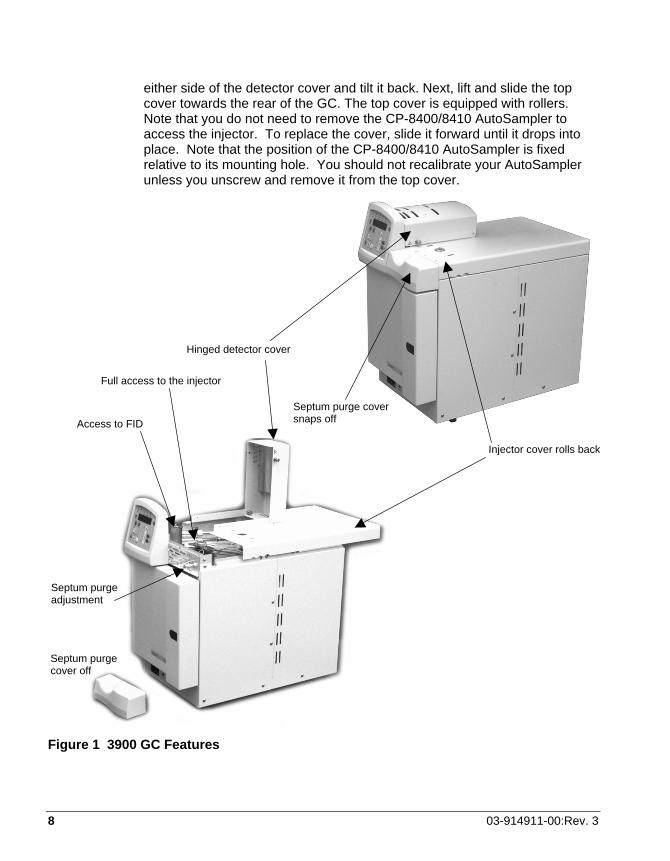
To access the injector and the top of the GC, unscrew the four retaining screws holding the top cover to the GC; undo the captured thumb screws on
8 03-914911-00:Rev. 3
either side of the detector cover and tilt it back. Next, lift and slide the top cover towards the rear of the GC. The top cover is equipped with rollers. Note that you do not need to remove the CP-8400/8410 AutoSampler to access the injector. To replace the cover, slide it forward until it drops into place. Note that the position of the CP-8400/8410 AutoSampler is fixed relative to its mounting hole. You should not recalibrate your AutoSampler unless you unscrew and remove it from the top cover.
Figure 1 3900 GC Features
Hinged detector cover
Access to FID
Septum purge cover off
Septum purge cover snaps off
Septum purge adjustment
Full access to the injector
Injector cover rolls back

3900 GC Operation Manual 9
Installation
Notes About Setting Up and Using Your 3900 GC The 3900 GC routinely operates at detection limits that are difficult to imagine and describe except as rather esoteric numbers. The GC will easily detect amounts of compounds that could not be visually observed even if they could be condensed and gathered into one place. The purity of the gases used with your 3900 GC are essential for sensitive operation. A Varian CP-Gas Clean Filter Kit (CP736530) should be installed if you have any question about your gas purity and definitely installed for the most demanding analyses.
All GCs require regular maintenance in order to operate at their highest efficiency. You will want to change the injector septum, injector liner, FID flame tip, gas filters and AutoSampler vials, wash bottle septa and solvents regularly. Varian has an extensive supply of quality maintenance parts for your 3900 GC and all of your chromatography needs including a comprehensive selection of the highest quality capillary columns available to chromatographers. Please visit the Varian internet site (www.varianinc.com), contact your Varian sales representative, or call your local Varian distribution center.
Preparing for Installation Refer to the Pre-Installation Instructions (03-914888-00) for site preparation.
To begin using your 3900 GC perform these steps:
Step 1 Unpacking and connecting your GC and its peripherals
Step 2 Establishing Ethernet communications (skip this section if you will not be connecting your GC to a Workstation or to a network)
Step 3 Connecting gases and entering setup information into your GC
Step 4 Calibrating the CP-8400/8410 AutoSampler

10 03-914911-00:Rev. 3
Step 1 – Unpacking and connecting your GC and its peripherals Unpacking the 3900 GC
Unbox and place your GC on the bench where it will be used. The instrument has been protected during shipment by various caps, plugs, and restraints. Prior to operating:
1. Remove the tape restraining the column oven door.
2. Remove any tape, tie-wraps, plastic plugs, or caps inside the column oven.
3. Cut the tie wrap and remove the two-pronged shipping dowel for oven fan motor from the hole in the GC left side panel. Save this shipping dowel in case you need to move your 3900 in the future.
4. Remove the carrier gas fitting cap on the rear panel.
5. Install the septum purge cover by snapping it onto the GC above the oven door.
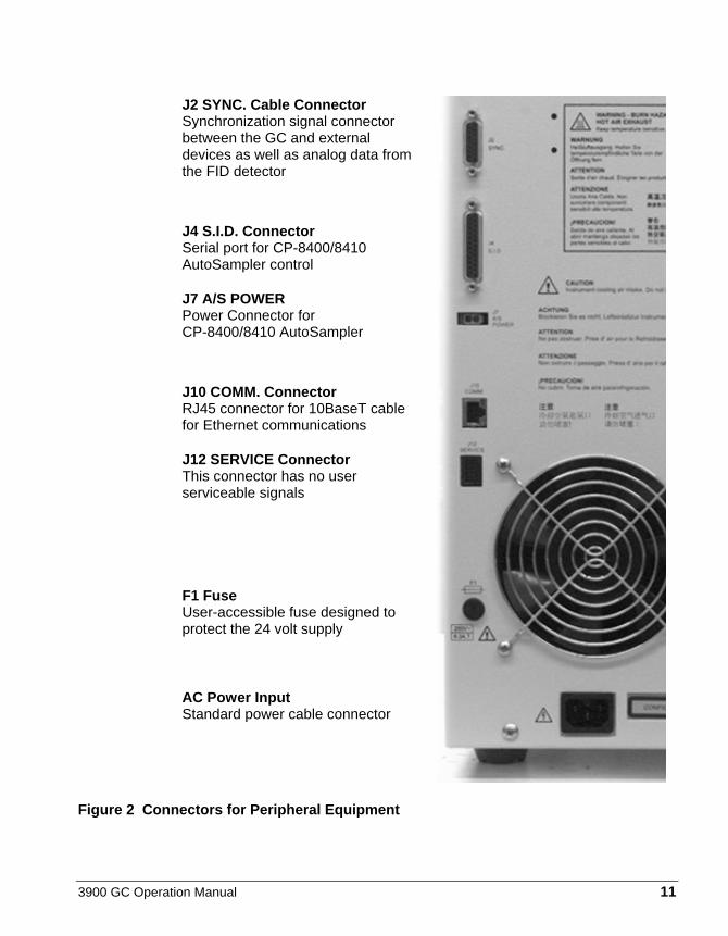
See Figure 2 for electrical and other connections to your 3900 GC.
3900 GC Operation Manual 11
J2 SYNC. Cable Connector Synchronization signal connector between the GC and external devices as well as analog data from the FID detector
J4 S.I.D. Connector Serial port for CP-8400/8410 AutoSampler control
J7 A/S POWER Power Connector for CP-8400/8410 AutoSampler
J10 COMM. Connector RJ45 connector for 10BaseT cable for Ethernet communications
J12 SERVICE Connector This connector has no user serviceable signals
F1 Fuse User-accessible fuse designed to protect the 24 volt supply
AC Power Input Standard power cable connector
Figure 2 Connectors for Peripheral Equipment

12 03-914911-00:Rev. 3
Column Installation Table 1 Column Insertion Depths
Device Insertion Depth CP-1177 3.7 cm 1041 Injector insert column until seated FID Detector 9.5 cm TCD Detector 3.0 cm
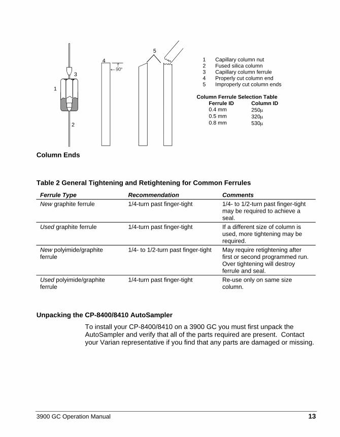
Before installing your column make certain that the ends of the column are in good shape and the column ends are cut perpendicularly
Preparing Column Ends
To ensure a leak-free connection of capillary columns, the ends of the column must be cut squarely and as smoothly as possible. To achieve this, a proper scoring tool is required. A ceramic scoring wafer (P/N 01-900158-00) is recommended. Before cutting the sealed ends of the column, slide the capillary column nut over the column end. Install the appropriate Vespel, graphite/Vespel, or graphite ferrule onto the column with the tapered end toward the capillary column nut. This procedure prevents contaminating the column with ferrule material.
1 Grasp the column securely between the thumb and forefinger of one hand. Score the column once lightly with the cutting tool.
2 Per figure below, bend column slightly to break it at the score mark. A magnifying lens (recommended 20X magnifier, P/N 00-997369-00) is necessary to determine the quality of the cut. (If small splinters of silica or some of the outer coating remains on the column end, it is advisable to make a fresh cut.)
3900 GC Operation Manual 13
Column Ends
Table 2 General Tightening and Retightening for Common Ferrules Ferrule Type Recommendation Comments New graphite ferrule 1/4-turn past finger-tight 1/4- to 1/2-turn past finger-tight
may be required to achieve a seal.
Used graphite ferrule 1/4-turn past finger-tight If a different size of column is used, more tightening may be required.
New polyimide/graphite ferrule
1/4- to 1/2-turn past finger-tight May require retightening after first or second programmed run. Over tightening will destroy ferrule and seal.
Used polyimide/graphite ferrule
1/4-turn past finger-tight Re-use only on same size column.
Unpacking the CP-8400/8410 AutoSampler To install your CP-8400/8410 on a 3900 GC you must first unpack the AutoSampler and verify that all of the parts required are present. Contact your Varian representative if you find that any parts are damaged or missing.
1 Capillary column nut 2 Fused silica column 3 Capillary column ferrule 4 Properly cut column end 5 Improperly cut column ends
Column Ferrule Selection Table
Ferrule ID Column ID 0.4 mm 250µ 0.5 mm 320µ 0.8 mm 530µ
3
1
4
5
2
14 03-914911-00:Rev. 3
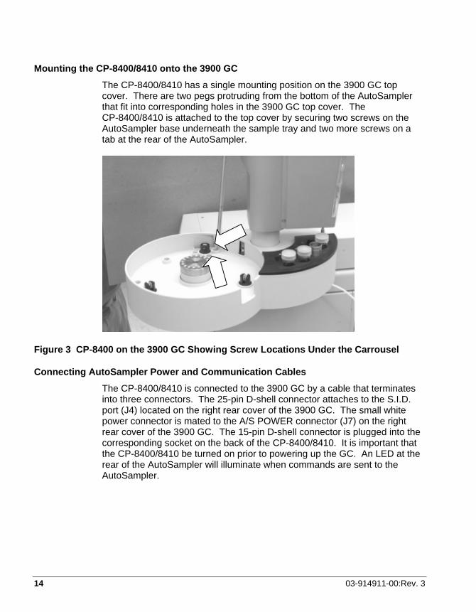
Mounting the CP-8400/8410 onto the 3900 GC The CP-8400/8410 has a single mounting position on the 3900 GC top cover. There are two pegs protruding from the bottom of the AutoSampler that fit into corresponding holes in the 3900 GC top cover. The CP-8400/8410 is attached to the top cover by securing two screws on the AutoSampler base underneath the sample tray and two more screws on a tab at the rear of the AutoSampler.
Figure 3 CP-8400 on the 3900 GC Showing Screw Locations Under the Carrousel
Connecting AutoSampler Power and Communication Cables The CP-8400/8410 is connected to the 3900 GC by a cable that terminates into three connectors. The 25-pin D-shell connector attaches to the S.I.D. port (J4) located on the right rear cover of the 3900 GC. The small white power connector is mated to the A/S POWER connector (J7) on the right rear cover of the 3900 GC. The 15-pin D-shell connector is plugged into the corresponding socket on the back of the CP-8400/8410. It is important that the CP-8400/8410 be turned on prior to powering up the GC. An LED at the rear of the AutoSampler will illuminate when commands are sent to the AutoSampler.
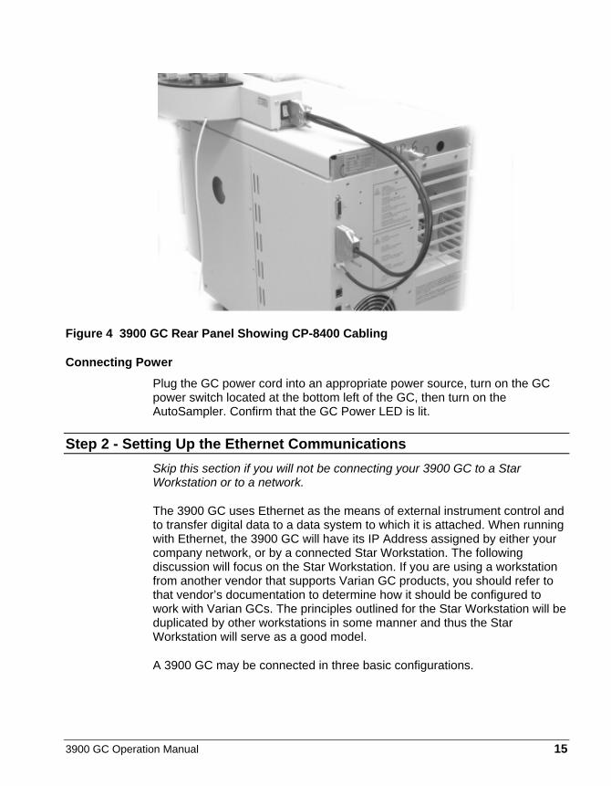
3900 GC Operation Manual 15
Figure 4 3900 GC Rear Panel Showing CP-8400 Cabling
Connecting Power Plug the GC power cord into an appropriate power source, turn on the GC power switch located at the bottom left of the GC, then turn on the AutoSampler. Confirm that the GC Power LED is lit.
Step 2 - Setting Up the Ethernet Communications Skip this section if you will not be connecting your 3900 GC to a Star Workstation or to a network.
The 3900 GC uses Ethernet as the means of external instrument control and to transfer digital data to a data system to which it is attached. When running with Ethernet, the 3900 GC will have its IP Address assigned by either your company network, or by a connected Star Workstation. The following discussion will focus on the Star Workstation. If you are using a workstation from another vendor that supports Varian GC products, you should refer to that vendor’s documentation to determine how it should be configured to work with Varian GCs. The principles outlined for the Star Workstation will be duplicated by other workstations in some manner and thus the Star Workstation will serve as a good model.
A 3900 GC may be connected in three basic configurations.
16 03-914911-00:Rev. 3
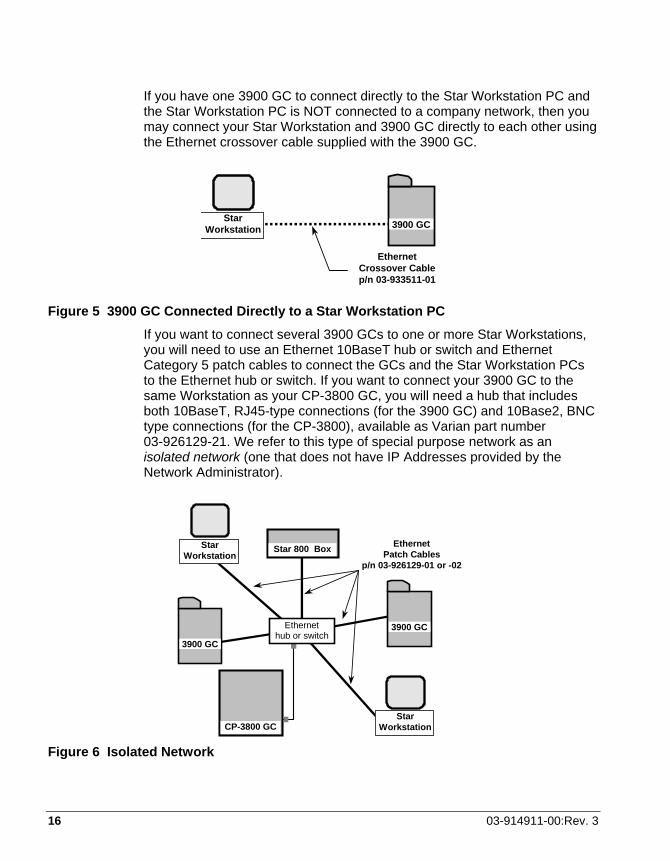
If you have one 3900 GC to connect directly to the Star Workstation PC and the Star Workstation PC is NOT connected to a company network, then you may connect your Star Workstation and 3900 GC directly to each other using the Ethernet crossover cable supplied with the 3900 GC.
Star Workstation
Ethernet Crossover Cable p/n 03-933511-01
3900 GC
Figure 5 3900 GC Connected Directly to a Star Workstation PC
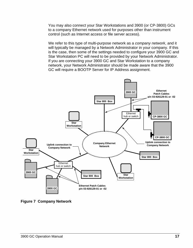
If you want to connect several 3900 GCs to one or more Star Workstations, you will need to use an Ethernet 10BaseT hub or switch and Ethernet Category 5 patch cables to connect the GCs and the Star Workstation PCs to the Ethernet hub or switch. If you want to connect your 3900 GC to the same Workstation as your CP-3800 GC, you will need a hub that includes both 10BaseT, RJ45-type connections (for the 3900 GC) and 10Base2, BNC type connections (for the CP-3800), available as Varian part number 03-926129-21. We refer to this type of special purpose network as an isolated network (one that does not have IP Addresses provided by the Network Administrator).
Star 800 Box Ethernet Patch Cables
p/n 03-926129-01 or -02
CP-3800 GC Star
Workstation
3900 GC
3900 GC
Star Workstation
Ethernet hub or switch
Figure 6 Isolated Network
3900 GC Operation Manual 17
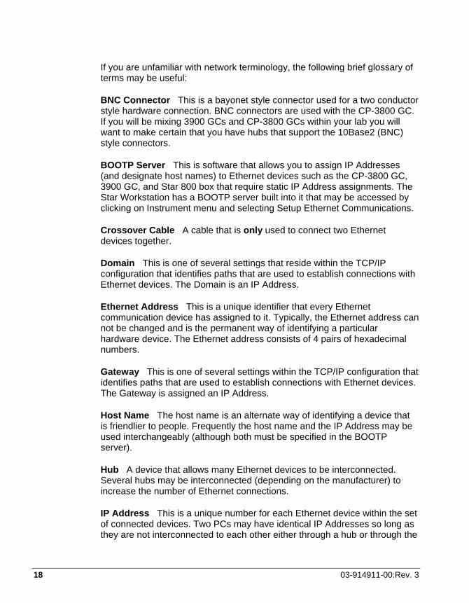
You may also connect your Star Workstations and 3900 (or CP-3800) GCs to a company Ethernet network used for purposes other than instrument control (such as Internet access or file server access).
We refer to this type of multi-purpose network as a company network, and it will typically be managed by a Network Administrator in your company. If this is the case, then some of the settings needed to configure your 3900 GC and Star Workstation PC will need to be provided by your Network Administrator. If you are connecting your 3900 GC and Star Workstation to a company network, your Network Administrator should be made aware that the 3900 GC will require a BOOTP Server for IP Address assignment.
Star Workstation
Star Workstation
Star Workstation
Star 800 Box
Ethernet hub or switch
Ethernet Patch Cables p/n 03-926129-01 or -02
Star 800 Box
Ethernet Patch Cables
p/n 03-926129-01 or -02
Uplink connection to Company Network
Uplink connection to Company Network
Star 800 Box
CP-3800 GC
CP-3800 GC
3900 GC
3900 GC
Company Ethernet Network
3900 GC
Ethernet hub or switch
Figure 7 Company Network
18 03-914911-00:Rev. 3
If you are unfamiliar with network terminology, the following brief glossary of terms may be useful:
BNC Connector This is a bayonet style connector used for a two conductor style hardware connection. BNC connectors are used with the CP-3800 GC. If you will be mixing 3900 GCs and CP-3800 GCs within your lab you will want to make certain that you have hubs that support the 10Base2 (BNC) style connectors.
BOOTP Server This is software that allows you to assign IP Addresses (and designate host names) to Ethernet devices such as the CP-3800 GC, 3900 GC, and Star 800 box that require static IP Address assignments. The Star Workstation has a BOOTP server built into it that may be accessed by clicking on Instrument menu and selecting Setup Ethernet Communications.
Crossover Cable A cable that is only used to connect two Ethernet devices together.
Domain This is one of several settings that reside within the TCP/IP configuration that identifies paths that are used to establish connections with Ethernet devices. The Domain is an IP Address.
Ethernet Address This is a unique identifier that every Ethernet communication device has assigned to it. Typically, the Ethernet address can not be changed and is the permanent way of identifying a particular hardware device. The Ethernet address consists of 4 pairs of hexadecimal numbers.
Gateway This is one of several settings within the TCP/IP configuration that identifies paths that are used to establish connections with Ethernet devices. The Gateway is assigned an IP Address.
Host Name The host name is an alternate way of identifying a device that is friendlier to people. Frequently the host name and the IP Address may be used interchangeably (although both must be specified in the BOOTP server).
Hub A device that allows many Ethernet devices to be interconnected. Several hubs may be interconnected (depending on the manufacturer) to increase the number of Ethernet connections.
IP Address This is a unique number for each Ethernet device within the set of connected devices. Two PCs may have identical IP Addresses so long as they are not interconnected to each other either through a hub or through the

3900 GC Operation Manual 19
internet. The IP Address consists of a series of four sets of decimal digits (between 1 and 3 characters typically) which encodes gateway and routing information that is used by the TCP/IP protocol to establish the most efficient and reliable connection. Without the IP Address, communications would be bogged down trying to establish connections to just the Ethernet address.
Patch Cable A cable that is used only to connect Ethernet devices to hubs or your company network.
RJ45 Connector This is a telephone jack style connector used for a several conductor style hardware connection (10BaseT). RJ45-style connectors are used by the 3900 GC.
TCP/IP This particular Ethernet protocol supports the 3900 GC, CP-3800 GC, and the Star 800 box. You may find several network protocols supported by your PC.
Overview The following steps are required to establish Ethernet communication with the 3900 GC, and are described in the following sections:
1. Load the appropriate software onto your Workstation PC.
2. Set the network properties of your Workstation PC.
3. Connect cables.
4. Set up the BOOTP server to assign an IP Address to your 3900 GC.
5. Configure your 3900 GC into a Star Workstation instrument.
Loading the Appropriate Software onto your Workstation PC Make sure that you have the necessary software installed on your Workstation. Follow the instructions that come with your upgrade/installation media to add 3900 GC control to your Workstation. Note that the Star Workstation refers to the 3900 GC as the “39XL”. The “3900” name is reserved for the 3900 GC which is dedicated to the 2100 GC/MS system.
20 03-914911-00:Rev. 3
Setting the Network Properties of your Workstation PC If you will be connecting your Workstation PC to your company network, you should contact your Network Administrator to properly set your PC’s network properties in the TCP/IP section.
If you will be connecting your Workstation PC directly to one or more GCs, with no connection to the company network, then you should set the following network properties on your PC:
Gateway 255.0.0.0 Domain 0.0.0.0 DNS Disabled WNS Configuration Disabled
Your Ethernet card will need to have an IP Address assigned to it. If your PC will not have any other Ethernet communications, there are no problems with IP Address conflicts, and you can set the IP Address to any value, for example 10.128.70.10.
Connecting Cables Power down both your PC and 3900 GC.
The optional Ethernet connection is made at the back of the 3900 GC (J10). There are two types of cables (crossover and patch), which are used as shown in the figures in the introduction to this section.
If you will be connecting a single GC to a single Workstation PC, you should use the crossover cable to make the direct connection. Otherwise, use the patch cable to connect the 3900 GC to a hub or to your company network.
Setting Up the BOOTP Server to Assign an IP Address to your 3900 GC This step only applies if you will be using the Star Workstation as the BOOTP Server to assign IP Addresses to your 3900 GC. If you are using a company network to assign the IP Addresses, skip to the next section.
• Power up your Star Workstation. Your 3900 GC should still be powered down.
• Invoke System Control on the Star Workstation and choose Setup Ethernet Communications from the Instrument drop down menu. Click on the Next key. The Setup Ethernet Ports dialog will display a table of instrument IDs (44, 45, 46, 47) with two boxes arrayed in rows after the instrument IDs.

3900 GC Operation Manual 21
• Click on the Setup key located at the right side of the window. The Setup BOOTP Server dialog will display a table with the headings Ethernet Address, IP Address, and Host Name will be displayed.
• Click on the check box labeled Manage IP Addresses from this workstation and select the number of IP Addresses you wish to have automatically assigned, (or select that you want to manually assign IP Addresses). If you are on a company network, your Network Administrator will provide the IP Addresses to be entered. Now OK each of the dialog screens that are displayed.
• Close System Control.
Configuring your 3900 GC into a Star Workstation Instrument
• Invoke (or re-invoke) System Control on the Star Workstation and choose Setup Ethernet Communications from the Instrument drop down menu. Click on the Next key. The Setup Ethernet Ports dialog will display a table of instrument IDs (44, 45, 46, 47) with two boxes arrayed in rows after the instrument IDs.
• Click on Setup to again display the Ethernet/IP Address table.
• Power-up your 3900 GC. If you are connecting multiple GCs, power up only one at a time, so you can identify which GC has which Ethernet address.
• Within about 90 seconds, the Ethernet address will be displayed for the 3900 GC (designated “39XL”). If you are in a network environment, this could take longer than 90 seconds. If you have chosen to manually assign IP Addresses, you should enter one now, otherwise, it should appear automatically in this dialog box. It is good practice to write down the Ethernet and IP Addresses for future reference.
• If the Star Workstation is the BOOTP server, enter a descriptive name in the Host Name field for your 3900 GC. This name may be provided by your Network Administrator if you are on a company network.
• OK the dialog and then click on one of the Instrument ID numbers (44, 45, 46, or 47) along the left side of the displayed table. After a few moments, the 3900 GC you just entered into the previous table will be displayed. Double click on the line designating that GC and OK the dialog box so that you are back to System Control. If your GC does not show up immediately you may click on the key next to module type and

22 03-914911-00:Rev. 3
choose “39XL” for the instrument you wish to use; you may then type in the IP Address manually.
• Once you are back in System Control, click on the Instrument menu again and choose Configuration. Your 3900 GC will be displayed as a “39XL” icon at the bottom of the screen. Click and drag the icon into any of the available instrument windows.
You have now established communication with your 3900 GC.
Step 3 - Connecting Gases and Entering Setup Information Connecting Gases
Carrier gas supplied from cylinders or manifolds should have a two-stage regulator having a zero to 100 psi low-pressure stage. Set cylinder regulator pressure to 80 psi.
Follow the steps below to connect gas supplies to your 3900 GC.
1. Cut required lengths of heat-cleaned 1/8″ copper tubing for the carrier gas plumbing. Clean the ends of the tubing with a metal file.
2. Slide a 1/8″ Swagelok nut, back ferrule, and front ferrule over one end of the copper tubing and attach to the outlet fitting on the cylinder regulator.
3. Push the copper tubing into the outlet fitting as far as it will go, then pull back very slightly and tighten 3/4-turn past finger-tight with a 7/16″ wrench.
Figure 8 Proper Ferrule Orientation
4. Push the other end of the copper tubing into the filter base inlet fitting as far as it will go, then pull back very slightly and tighten 3/4-turn past finger-tight with a 7/16″ wrench.
1/8" Copper Tubing
Swagelok Nut
Back Ferrule
Front Ferrule
3900 GC Operation Manual 23
5. Connect another length of copper tubing to the outlet of the filter base using a 1/8″ Swagelok® nut and back and front ferrules as above.
6. Push the copper tubing into the bulkhead fitting on the back of the 3900 GC as far as it will go, then pull back very slightly and tighten 3/4-turn past finger-tight with a 7/16″ wrench.
7. Make sure the gas supply control valve, which controls gas pressure to the GC, is completely closed. Open this valve slowly and monitor the pressure gauges on the dual stage regulator. The first pressure gauge should now read the pressure of the cylinder.
8. Cautiously turn the regulator valve to supply gas to the GC. Watch the pressure gauge closely and adjust the pressure to 80 psi.
9. Install the carrier gas filter cartridge into the filter base following instructions provided in the Accessory Kit.
10. Leak check all fittings (see page 43).
11. Repeat this process as necessary for detector gases. However, use a secondary pressure of 60 for air and 40 for H2.
Entering Setup Information into Your GC Enter Setup (use the keypad if your 3900 GC is equipped with one to perform setup, otherwise perform the setup from the Workstation status and control window in the System Control application) and enter essential parameters such as column diameter, length, and carrier gas.
Step 4 - Calibrating the CP-8400/8410 AutoSampler Skip this section if you do not have a CP-8400/8410 AutoSampler on your 3900 GC.
Calibration is performed similarly to the description in the CP-8400/8410 Operator’s Manual (03-914852-00). If your 3900 GC is equipped with a keypad, then you will follow the instructions in setup as they are presented to you on the keypad display and in the CP-8400/8410 Operator’s Manual. If your 3900 GC is not equipped with a keypad, follow the instructions in this manual and in the CP-8400/8410 Operator’s Manual. The major difference is that the calibration will be performed using the Workstation for versions of the 3900 GC that do not have a local user interface. The goal of the calibration procedure is to align the AutoSampler needle with the first vial and with the injector.

24 03-914911-00:Rev. 3
NOTE: One basic rule associated with this calibration concerns rotation of the tower and carrousel; to assure consistent operation, always approach the final calibration position with clockwise movements. To help facilitate this rule, the carrousel will back up 10 steps when a counterclockwise action is selected but will move one step when a clockwise action is selected.
Vial Calibration Calibrating the Vial 0 (or Vial 1 if CP-8410) position involves manipulating the positions of three different components. The object of the calibration is to position the needle as closely as possible over the center of the sampling target area of the vial. Upon starting the calibration procedure on the Workstation, the CP-8400/8410 will rotate the tower, rotate the carrousel (on the CP-8400 only), and lower the syringe sled to the approximate location of Vial 0 (or Vial 1 if CP-8410). After the CP-8400/8410 has found the approximate Vial 0 (or Vial 1) position and before going further, visually check that the syringe sled is not resting on the vial top. If it is, use the controls in the Workstation to move the sled so that the needle guide is approximately 1 mm above the vial. Start the calibration process by adjusting the tower position as shown in Figure 9.
Figure 9 Tower Position Calibration for CP-8400 Vial 0 or CP-8410 Vial 1

3900 GC Operation Manual 25
Next, for CP-8400 users only, set the carrousel position. You may have to switch back and forth between the tower and carrousel one or more times to determine the optimum rotational positions. Finally, adjust the Syringe sled height so that the needle guide is just barely above the vial cap. You should be able to see about a paper’s thickness of space between the needle guide and the top of the vial cap. The penetration depth into the vial is measured from the bottom of the needle guide, so this height will give you optimum penetration depth.
Figure 10 Correct Vial 0/Vial 1 Calibration
When the Vial 0/Vial 1 calibration is correctly set, the needle guide should be positioned over the vial top as shown above. At this point, complete the calibration of your CP-8400/8410 on your 3900 GC by choosing Complete Calibration on your Workstation window.

26 03-914911-00:Rev. 3
Injector Calibration After completing the vial position calibration you will need to calibrate the injector position. To do this, begin the injector calibration from your Workstation. The syringe tower will rotate so that it is approximately over the injector and the syringe sled will descend to a point near the top of the injector. Use the controls provided on the Workstation to position the needle guide so that it is just covering but not depressing the cone on the inject switch as shown in Figure 11.
Figure 11 Correct Syringe Sled/Injector Position
3900 GC Operation Manual 27
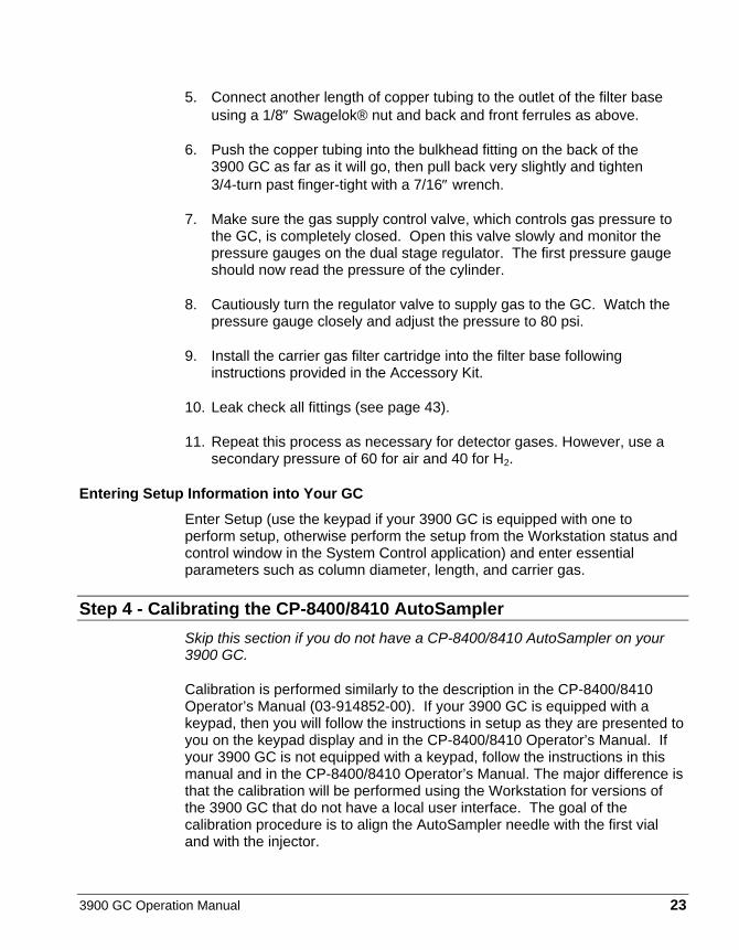
Move the tower so that it is directly over the needle cone on the injector. Lower the tower so that the needle cone of the injector fits into the counterbore of the CP-8400/8410 needle guide. The injector switch should not be compressed. If the injector switch is compressed, you may experience ‘syringe sled’ errors during AutoSampler operation. If you are uncertain whether the inject switch is compressing, it is better to raise the syringe slide 1 or 2 steps.
Figure 12 Correct Injector Calibration
When you have completed the tower and sled movements, the system should look as in the figure above.
Complete the calibration by choosing Complete Calibration from your Workstation calibration window. Your CP-8400/8410 AutoSampler should now be ready to be used with your 3900 GC.
If you have not yet reviewed the CP-8400/8410 manual, you may wish to do so now. The Star and Saturn Workstations fully support the features of your AutoSampler.
Please refer to Workstation on-line Help for detailed information on using either the Star or Saturn Workstation.

28 03-914911-00:Rev. 3
Installation Conclusion If you do not have a CP-8400 or a CP-8410 AutoSampler/AutoInjector, you are now ready to begin using your 3900 GC. The rest of this manual provides more detailed descriptions of how to set and use the various aspects of your GC. Please refer to the manual if some aspect of the instrument is not immediately clear or if you would like to understand more how this GC operates.

3900 GC Operation Manual 29

30 03-914911-00:Rev. 3
Figure 13 3900 GC Keypad
Green keys cause changes to take place immediately, for instance pressing NEW LINE will cause a new line to be added to a method time program table.
Yellow keys take you to entries that can be changed such as method sections, setup and commands.
Blue keys are display actions only. They display status or help navigate the display, they can also be used to cancel an edit before it is accepted by pressing ENTER.

3900 GC Operation Manual 31
Keypad Keys and Their Functions
STATUS
The STATUS key allows you to observe various instrument setpoints and actual conditions for thermal and gas control settings. Once you are in the Status display mode, you may use either ENTER to scroll down through the Status pages or UP LINE to scroll up through the Status pages. Note that Status wraps around; if you were to press ENTER until you observe the last line of Status and then press ENTER again, you would observe the first Status page displayed again. Similarly, if you were to press UP LINE immediately after entering Status, you would observe the last page of the Status display mode. Status pages are summarized below:
• General Status (Instrument State, vial # if A/S present, run time and column oven temperature).
• Thermal zones actual temperatures
• Active method
• Injector EFC Pressure Status
• Injector EFC Flow Status
• Detector EFC Flow and Signal status
• Software version
• Error Log
STATUS performs no operations on the GC except to change the display. Thus, you may cancel any change to an editable field by pressing STATUS instead of ENTER.
UP LINE
UP LINE simply moves the display to the immediate preceding page for viewing. It does not operate on any function of the GC other than the currently displayed page. If the display is already at the top of a section, then pressing UP LINE will take you to the last line of the section.

32 03-914911-00:Rev. 3
START
The START key operates on your 3900 GC in one of two ways:
1. If neither a CP-8400 nor a CP-8410 is present, pressing START will cause the 3900 GC to execute the currently active method. The run time will begin incrementing and any time programs will be executed.
2. If either a CP-8400 or a CP-8410 is present, pressing START will allow you to either perform an AutoInjection or simply start the currently active method. The default action is to perform an AutoInjection. Upon accepting the AutoInjection selection you will be prompted for the sample vial, the sample volume and the number of replicate injections you wish to perform. You may cancel an AutoInjection by pressing one of the blue keys on the keypad.
3. Once a run is started you may either allow the run to complete or press the STOP key to terminate it.
STOP
The purpose of the STOP key is to terminate an executing method and cycle back to initial conditions. The STOP key is also used to interrupt Local Automation.
ENTER
The ENTER key performs two functions:
1. If an editable field has been changed, the ENTER key will accept and execute that change.
2. If no changes have been made, then the ENTER key will advance to the next line on the display.
If you edit a field, you will press ENTER to accept the edited value and advance to the next line of the display. Note that once you change the entry for a field a flashing underscore cursor will be displayed showing that the field is being edited. If the underscore cursor is flashing and you do not want to accept the changed field, you may press the blue UP LINE key located at the left side of the display to discard any edits that may have been made to that field. If you press ENTER, the edits will be accepted.

3900 GC Operation Manual 33
NEW LINE and DELETE LINE
The NEW LINE and DELETE LINE keys operate on Method tables. If you wish to add a program line (step) to the External Events (relay) program, Injector Split Ratio table, Column Oven program, or the Detector Range/Attenuation time program you should press NEW LINE. If you have currently displayed the last line of a table on the display (noted by the expression 3/3 in the example below), then pressing NEW LINE will append a line to the end of the table.
If you are in the middle of a table, pressing NEW LINE will insert a line into the table immediately after the step currently shown on the display. Note that there are either two, three, or four display pages for each line. Each page shows a part of the table line being operated on. The figure below demonstrates how the table lines are displayed:
Figure 14 Table Operations with Local User Interface
Thus, each table line is represented by multiple display pages (in this case three display pages). The DELETE LINE key will remove the currently displayed step from the table. Please note that it does not matter which of the fields for a given step are displayed in the table. All table entries belonging to Step 1, for instance, are part of the same table entry.
34 03-914911-00:Rev. 3
SETUP
The parameters available from the SETUP key are summarized in the Setup Outline below (note that if you do not have either a CP-8400 or CP-8410 installed you will not see the AutoSampler Setup section):
Setup Outline Language English French Spanish Italian German Japanese (Katakana) EFC (type 1 for 1177 injector) Gas Type He, N2, H2 Outlet Atm, Vacuum Units psi, kPa, Barr Gas Saver Timeout 0 (off) to 999.99 min (If the GC is idle for the set period of time, the Gas Saver flow rate is
implemented and an advisory fault is spawned. Activate a Method to clear the fault.)
Gas Saver Flowrate 0 to 100 mL/min Splitless Vent Flow 0 to 100 mL/min AutoCalibrate EFC AutoCalibrate DFC Septum Purge Calibrate EFC (type 4 for 1041 injector) Gas Type He, N2, H2 Outlet Atm, Vacuum Units psi, kPa, Barr Gas Saver Timeout 0 (off) to 999.99 min (If the GC is idle for the set period of time, the Gas Saver flow rate is
implemented and an advisory fault is spawned. Activate a Method to clear the fault.)
Gas Saver Flowrate 0 to 100 mL/min Splitless Vent Flow 0 to 100 mL/min AutoCalibrate EFC AutoCalibrate EFC Column Length 0.01 to 200.00m I.D. 20 to 530 µm, packed Standby Temperature 50 to 450 ºC Standby Time-out 0.00 (off) to 999.99 min.

3900 GC Operation Manual 35
Temperature Limits Column Temperature zone upper limit (50 to 450 ºC) Detector Temperature zone upper limit (50 to 450 ºC) Injector Temperature zone upper limit (50 to 450 ºC) AutoSampler Calibrate Vial 0/1 Injector Syringe Volume 5, 10, 100, 250 µL Date/Time Date MM/DD/YY DD/MM/YY Time Password Set keypad Password Locked/Unlocked Enter Password ********
COMMAND
COMMAND gives you access to a variety of operations that are not properly associated with either method program execution or the GC configuration.
Command Outline Method Actions Activate Method Methods 1, 2, 3, 4, or 5 Copy Method Methods 1, 2, 3, 4, 5 to 1, 2, 3, 4, 5 Set Method to Defaults Methods 1, 2, 3, 4, or 5 AutoSampler Actions Change Syringe Beeper On/Off Reset Plunger Stroke Counter Plunger Stroke # Warning Limit Syringe Penetration Speed into Injector Syringe Depth into Injector Detector Actions AutoZero Now! Clear AutoZero! Ignite Flame Now! (FID only) Remote Control Enable/Disable a remote Workstation
The following sections outline the parameters that are available under each method icon.
36 03-914911-00:Rev. 3
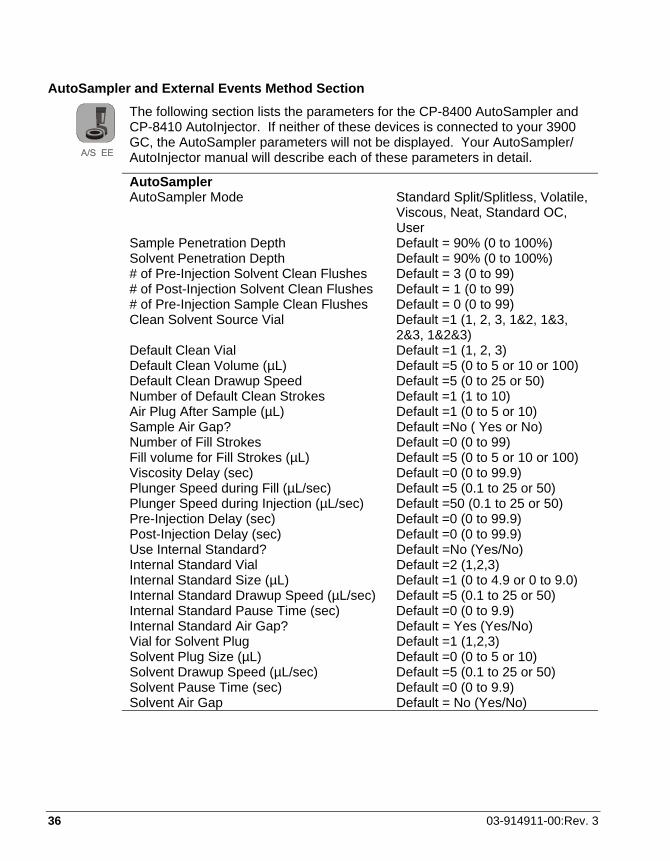
AutoSampler and External Events Method Section
The following section lists the parameters for the CP-8400 AutoSampler and CP-8410 AutoInjector. If neither of these devices is connected to your 3900 GC, the AutoSampler parameters will not be displayed. Your AutoSampler/ AutoInjector manual will describe each of these parameters in detail.
AutoSampler AutoSampler Mode Standard Split/Splitless, Volatile,
Viscous, Neat, Standard OC, User
Sample Penetration Depth Default = 90% (0 to 100%) Solvent Penetration Depth Default = 90% (0 to 100%) # of Pre-Injection Solvent Clean Flushes Default = 3 (0 to 99) # of Post-Injection Solvent Clean Flushes Default = 1 (0 to 99) # of Pre-Injection Sample Clean Flushes Default = 0 (0 to 99) Clean Solvent Source Vial Default =1 (1, 2, 3, 1&2, 1&3,
2&3, 1&2&3) Default Clean Vial Default =1 (1, 2, 3) Default Clean Volume (µL) Default =5 (0 to 5 or 10 or 100) Default Clean Drawup Speed Default =5 (0 to 25 or 50) Number of Default Clean Strokes Default =1 (1 to 10) Air Plug After Sample (µL) Default =1 (0 to 5 or 10) Sample Air Gap? Default =No ( Yes or No) Number of Fill Strokes Default =0 (0 to 99) Fill volume for Fill Strokes (µL) Default =5 (0 to 5 or 10 or 100) Viscosity Delay (sec) Default =0 (0 to 99.9) Plunger Speed during Fill (µL/sec) Default =5 (0.1 to 25 or 50) Plunger Speed during Injection (µL/sec) Default =50 (0.1 to 25 or 50) Pre-Injection Delay (sec) Default =0 (0 to 99.9) Post-Injection Delay (sec) Default =0 (0 to 99.9) Use Internal Standard? Default =No (Yes/No) Internal Standard Vial Default =2 (1,2,3) Internal Standard Size (µL) Default =1 (0 to 4.9 or 0 to 9.0) Internal Standard Drawup Speed (µL/sec) Default =5 (0.1 to 25 or 50) Internal Standard Pause Time (sec) Default =0 (0 to 9.9) Internal Standard Air Gap? Default = Yes (Yes/No) Vial for Solvent Plug Default =1 (1,2,3) Solvent Plug Size (µL) Default =0 (0 to 5 or 10) Solvent Drawup Speed (µL/sec) Default =5 (0.1 to 25 or 50) Solvent Pause Time (sec) Default =0 (0 to 9.9) Solvent Air Gap Default = No (Yes/No)
3900 GC Operation Manual 37
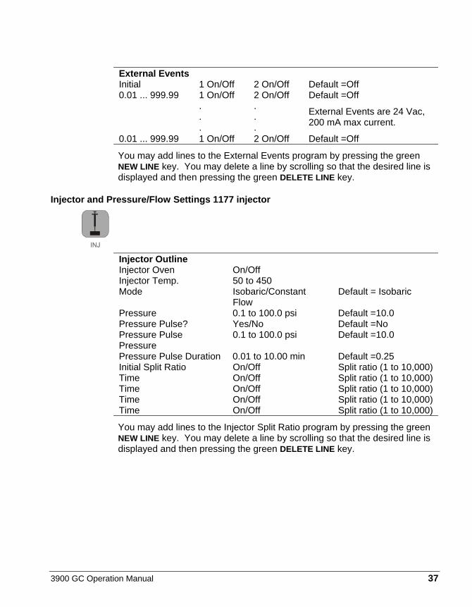
External Events Initial 1 On/Off 2 On/Off Default =Off 0.01 ... 999.99 1 On/Off 2 On/Off Default =Off . . . . . .
External Events are 24 Vac, 200 mA max current.
0.01 ... 999.99 1 On/Off 2 On/Off Default =Off
You may add lines to the External Events program by pressing the green NEW LINE key. You may delete a line by scrolling so that the desired line is displayed and then pressing the green DELETE LINE key.
Injector and Pressure/Flow Settings 1177 injector
Injector Outline Injector Oven On/Off Injector Temp. 50 to 450 Mode Isobaric/Constant
Flow Default = Isobaric
Pressure 0.1 to 100.0 psi Default =10.0 Pressure Pulse? Yes/No Default =No Pressure Pulse Pressure
0.1 to 100.0 psi Default =10.0
Pressure Pulse Duration 0.01 to 10.00 min Default =0.25 Initial Split Ratio On/Off Split ratio (1 to 10,000) Time On/Off Split ratio (1 to 10,000) Time On/Off Split ratio (1 to 10,000) Time On/Off Split ratio (1 to 10,000) Time On/Off Split ratio (1 to 10,000)
You may add lines to the Injector Split Ratio program by pressing the green NEW LINE key. You may delete a line by scrolling so that the desired line is displayed and then pressing the green DELETE LINE key.

38 03-914911-00:Rev. 3
Injector and Pressure/Flow Settings 1041 injector
Injector Outline Injector Oven On/Off Injector Temp. 50 to 450 Mode Isobaric/Constant Flow Default = Isobaric Pressure 0.1 to 100.0 psi Default =10.0 Hold Time 0.00 to 999.99 Default = 20.00 Total Flow 0.1 to 100.00 Default = 20 Pressure (0.1 to 100.0) Ramp rate (0.1 to 400.0) Hold Time (0.00 to
999.99 Pressure (0.1 to 100.0) Ramp rate (0.1 to 400.0) Hold Time (0.00 to
999.99 Pressure (0.1 to 100.0) Ramp rate (0.1 to 400.0) Hold Time (0.00 to
999.99 Pressure (0.1 to 100.0) Ramp rate (0.1 to 400.0) Hold Time (0.00 to
999.99 Pressure (0.1 to 100.0) Ramp rate (0.1 to 400.0) Hold Time (0.00 to
999.99 Event Time (0.00 to 999.99)
Total Flow (0.1 to 100.0)
Event Time (0.00 to 999.99)
Total Flow (0.1 to 100.0)
Event Time (0.00 to 999.99)
Total Flow (0.1 to 100.0)
Event Time (0.00 to 999.99)
Total Flow (0.1 to 100.0)
Event Time (0.00 to 999.99)
Total Flow (0.1 to 100.0)
You may add lines to the Pressure and Total Flow programs by pressing the green NEW LINE key. You may delete a line by scrolling so that the desired line is displayed and then pressing the green DELETE LINE key.

3900 GC Operation Manual 39
Column Oven
Oven Outline Stabilize Time 0.0 to 10.0 minutes Initial Temp. 30 to 450 ----- Hold (0 to 999.99 min) Ramp End Temp 30 to 450 Rate Hold (0 to 999.99 min) Ramp End Temp 30 to 450 Rate Hold (0 to 999.99 min) Ramp End Temp 30 to 450 Rate Hold (0 to 999.99 min) Ramp End Temp 30 to 450 Rate Hold (0 to 999.99 min) Ramp End Temp 30 to 450 Rate Hold (0 to 999.99 min) Ramp End Temp 30 to 450 Rate Hold (0 to 999.99 min) Ramp End Temp 30 to 450 Rate Hold (0 to 999.99 min) Column Coolant Enable/Disable
Enabled or Disabled
Coolant Threshold Temperature
50 to 250
You may add lines to the Column Oven program by pressing the green NEW LINE. You may delete a line by scrolling so that the desired line is displayed and then pressing the green DELETE LINE key.
Detector and Detector Flow Settings FID
Detector Oven On/Off Temperature 50 to 450 Electronics On/Off Range (9, 10, 11, 12) AutoZero Yes/No Time Constant Slow (Fast/Slow) Attenuation (1 to 1024) Initial Range Attenuation A/Z Time Range Attenuation A/Z Time Range Attenuation A/Z Time Range Attenuation A/Z Time Range Attenuation A/Z H2 Flow 0.00 to 50.00 Air Flow 0.00 to 500.0 Makeup Flow 0.00 to 50.00
40 03-914911-00:Rev. 3
You may add lines to the Detector Attenuation program by pressing the green NEW LINE key. You may delete a line by scrolling so that the desired line is displayed and then pressing the green DELETE LINE key.
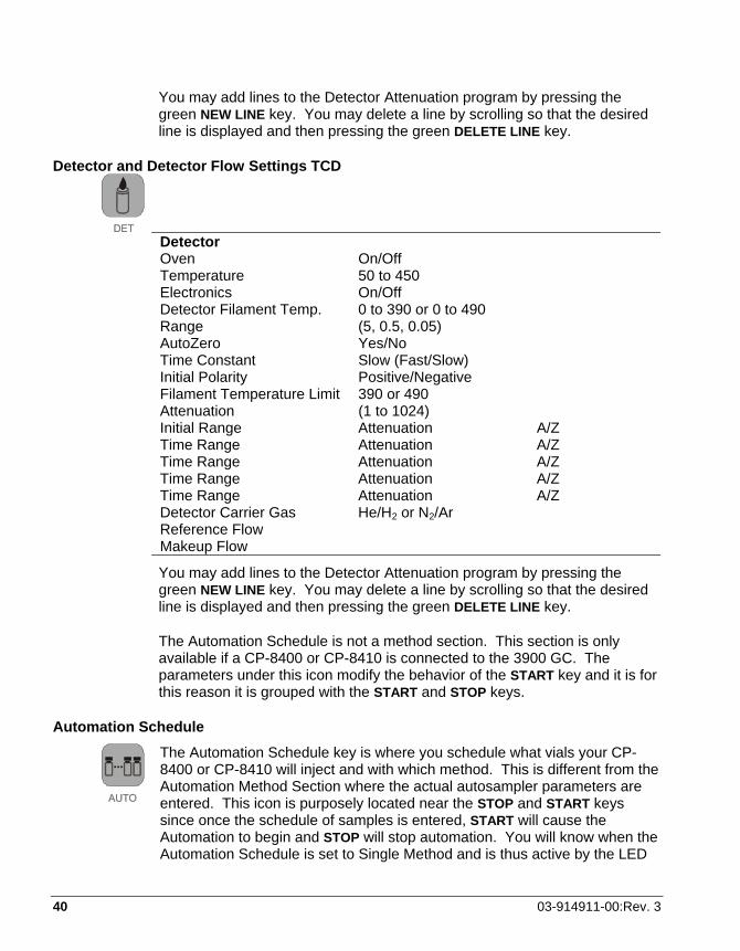
Detector and Detector Flow Settings TCD
Detector Oven On/Off Temperature 50 to 450 Electronics On/Off Detector Filament Temp. 0 to 390 or 0 to 490 Range (5, 0.5, 0.05) AutoZero Yes/No Time Constant Slow (Fast/Slow) Initial Polarity Positive/Negative Filament Temperature Limit 390 or 490 Attenuation (1 to 1024) Initial Range Attenuation A/Z Time Range Attenuation A/Z Time Range Attenuation A/Z Time Range Attenuation A/Z Time Range Attenuation A/Z Detector Carrier Gas He/H2 or N2/Ar Reference Flow Makeup Flow
You may add lines to the Detector Attenuation program by pressing the green NEW LINE key. You may delete a line by scrolling so that the desired line is displayed and then pressing the green DELETE LINE key.
The Automation Schedule is not a method section. This section is only available if a CP-8400 or CP-8410 is connected to the 3900 GC. The parameters under this icon modify the behavior of the START key and it is for this reason it is grouped with the START and STOP keys.
Automation Schedule
The Automation Schedule key is where you schedule what vials your CP-8400 or CP-8410 will inject and with which method. This is different from the Automation Method Section where the actual autosampler parameters are entered. This icon is purposely located near the STOP and START keys since once the schedule of samples is entered, START will cause the Automation to begin and STOP will stop automation. You will know when the Automation Schedule is set to Single Method and is thus active by the LED
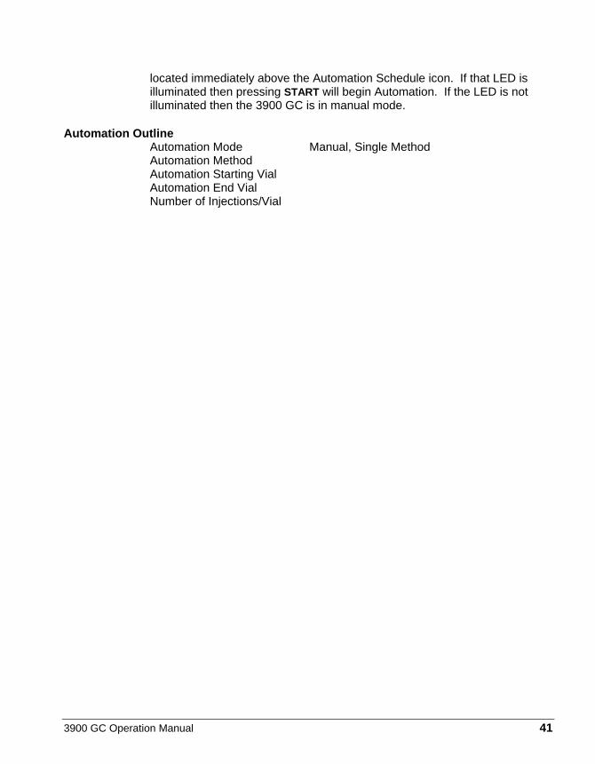
3900 GC Operation Manual 41
located immediately above the Automation Schedule icon. If that LED is illuminated then pressing START will begin Automation. If the LED is not illuminated then the 3900 GC is in manual mode.
Automation Outline Automation Mode Manual, Single Method Automation Method Automation Starting Vial Automation End Vial Number of Injections/Vial
42 03-914911-00:Rev. 3
Maintenance
It is important for the GC user to learn general maintenance techniques and perform them on a regular basis. Some common GC maintenance procedures are changing septa and injector inserts, checking for leaks, conditioning columns, and changing filters.
Note that a qualified Varian service representative should perform service procedures, such as repair or replacement of electronic components. For maintenance problems where mechanical or electrical assemblies need to be repaired or replaced, please call your local Varian service center.
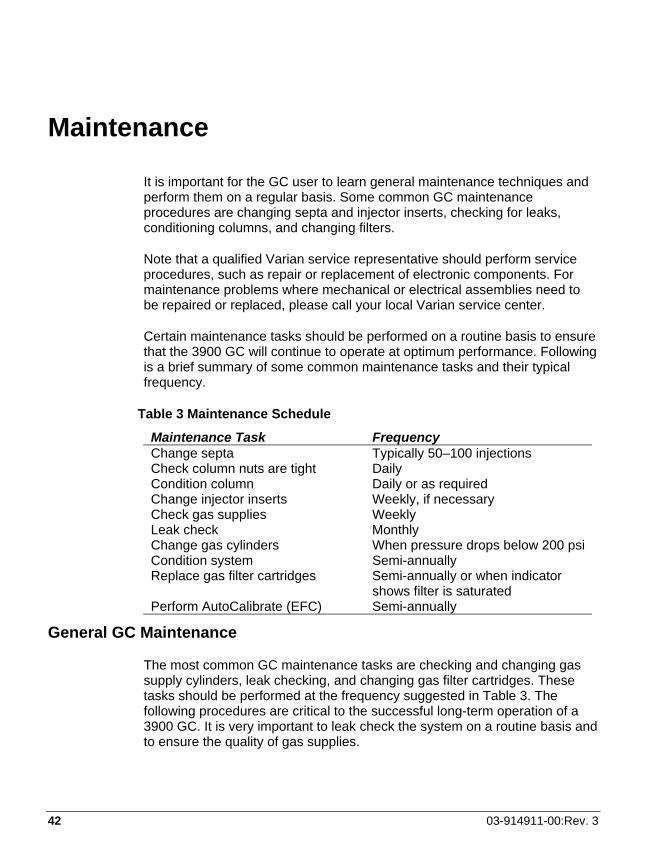
Certain maintenance tasks should be performed on a routine basis to ensure that the 3900 GC will continue to operate at optimum performance. Following is a brief summary of some common maintenance tasks and their typical frequency.
Table 3 Maintenance Schedule Maintenance Task Frequency Change septa Typically 50–100 injections Check column nuts are tight Daily Condition column Daily or as required Change injector inserts Weekly, if necessary Check gas supplies Weekly Leak check Monthly Change gas cylinders When pressure drops below 200 psi Condition system Semi-annually Replace gas filter cartridges Semi-annually or when indicator
shows filter is saturated Perform AutoCalibrate (EFC) Semi-annually
General GC Maintenance
The most common GC maintenance tasks are checking and changing gas supply cylinders, leak checking, and changing gas filter cartridges. These tasks should be performed at the frequency suggested in Table 3. The following procedures are critical to the successful long-term operation of a 3900 GC. It is very important to leak check the system on a routine basis and to ensure the quality of gas supplies.
3900 GC Operation Manual 43
Checking and Renewing Gas Supplies
The pressure of the various GC gas supplies should be checked on a weekly basis and the following guidelines used for frequency of renewing supplies.
The carrier gas supply cylinder should be changed when its pressure drops below 200 psi. This ensures that high purity carrier gas is always supplied to the instrument. With typical usage on one gas chromatograph, a cylinder of carrier gas should last for three to six months. When a new cylinder is installed, the regulator and tubing should be purged with carrier gas before connecting to the GC. This will avoid introducing a large amount of air into the GC.
Leak Checking Leak checking is one of the most important maintenance tasks performed on a GC. Leaks in the GC system may lead to poor chromatographic performance or may damage components such as the analytical column. The presence of oxygen in the GC carrier gas at elevated temperatures can lead to permanent column phase degradation. While the use of an oxygen filter on the carrier supply to the instrument can help, leaks downstream of the filter are generally more likely to be the problem.
CAUTION
The use of soap-based leak detection fluids is not recommended for a high performance capillary Gas Chromatograph due to the danger of introducing contaminants into the system.
The most important step in leak checking is to verify that the GC system can hold pressure. This is done by removing the column from the injector, sealing all exits from the injector and pressurizing the system. Use the following procedure to leak check a 3900 GC injector.
Required Materials
no-hole ferrule unused septum column fitting crescent wrench supply valve leak detector
Note: When conducting leak check procedures it is important to completely seal all carrier gas exits, including septum purge and split vent outlets.

44 03-914911-00:Rev. 3
WARNING:BURN HAZARD
The injector nut may be hot. Lower the injector temperature to 50 °C and permit the injector nut to cool before proceeding.
1. Remove injector septum nut and install a new septum. An older septum can often be the source of a substantial leak.
2. Remove the column from the injector. Use the appropriate nut and ferrule to seal the base of the injector. For capillary systems use a capillary nut (03-949551-00) with a no-hole ferrule (28-694590-01).
3. The septum purge and split vent outlets must be sealed. The septum purge outlet is located on the top frame surrounding the column oven, behind the cap above the column oven door. The split vent outlet is located on the left side panel of the 3900 GC. Seal the septum purge by removing the fitting from the septum purge valve and replacing it with a blank off plug (28-247071-01). You may set the Splitless Vent Flow in the 3900 GC configuration to a flow of 0 and set the split ratio to off.
4. With all outlet ports plugged, pressurize the system to 80 psi. This can be accomplished by setting the isobaric pressure to 80 psi either at the 3900 GC Keypad or via downloaded Workstation Method.
5. Shut off the carrier supply at the source and monitor the displayed pressure at the GC for five minutes. The pressure should not drop more than 4 psi in five minutes.
Leak checking ensures that there are no leaks in the GC system up to and including the injector assembly. If the indicated pressure on the GC drops by more than 4 psi during the five minute test period, this indicates that there is a leak in the system. Finding such a leak, particularly if it is a small leak, can be very difficult. In general, the best approach is to systematically go through the pneumatic system from the source and tighten each fitting until the leak is eliminated. It is important to note that leaks are often found in the carrier gas supply to the GC.
Locate leaks with an electronic leak detector only. An electronic helium leak detector is available from Varian (CP-87610). This device can detect helium concentration in the air as low as 2 ppm and is very effective at identifying the precise location of a helium leak from a GC system.
3900 GC Operation Manual 45
Gas Filter Cartridge Replacement
The 3900 GC requires extremely pure gas for optimal performance. Make sure you use gas filters for best operation. If you are using the recommended CP736530 filter kits, replacement filters can be ordered from Varian. See the Replacement Parts list on page 69.
Injector Maintenance The injector is the component of the gas chromatograph that requires the most frequent maintenance. The sample is deposited in the injector, leading to potential contamination and build up of non-volatile deposits. The most frequent injector maintenance is septum replacement. Insert replacement and injector cleaning are also very common.
Septum Replacement The injector septum is an expendable part and must be replaced on a routine basis. The frequency of replacement depends on the number of injections and whether the injections are by hand or with an autosampler. In general the septum should be replaced every 50–100 injections or when symptoms of a septum leak are seen. These symptoms include changing retention times, reduced detector response, or a drop in column head pressure.
WARNING:BURN HAZARD
The injector nut may be hot. Lower the injector temperature to 50 °C and permit the injector nut to cool before proceeding.
1. Turn off the carrier gas supply to the injector.
2. Remove the injector nut by turning it counterclockwise.
3. Remove the old septum using metal tweezers or a septum pick (72-000084-00). Do not to handle any internal parts of the injector with hands or gloves.
4. Install the new septum, again using tweezers to avoid contaminating the injector.
5. Replace the injector nut and tighten it finger-tight until you feel resistance from the septum, then tighten an extra 1/4 turn. Turn on the carrier gas supply.

46 03-914911-00:Rev. 3
On occasion to save time you may want to change a septum while the injector is hot. Use an injector wrench (03-908423-00) to remove and reinstall the injector nut. In all instances the column oven should be cool before removing the injector nut to minimize damage to the column caused by air entering the injector when the septum is removed.
Insert Replacement The CP-1177 is a Split/Splitless capillary injector. Typically, to change from Split operation to Splitless may involve changing the injector insert. The insert should also be cleaned or replaced on a routine basis. This is especially important when dirty samples are being analyzed.
Removing the Glass Insert
Referring to Figure 15, follow these steps to remove the glass insert from the CP-1177 Injector.
WARNING:BURN HAZARD
The injector nut may be hot. Lower the injector temperature to 50 °C and permit the injector nut to cool before proceeding.
1. Use the injector nut wrench to remove the injector nut (Item 1). Place the nut on a clean surface (e.g., clean tissue).
2. With tweezers or septum pick, lift the edge of the septum (Item 2). Remove the septum.
Note: Replace the injector septum each time the glass insert is replaced.
3. Remove the inject switch by unscrewing the retaining nut.
4. Unscrew the two captive screws holding the septum purge head to the base. Carefully move this assembly straight up until it clears the top of the insert. The septum purge line and carrier gas supply lines may hinder movement of the purge head somewhat.
5. Use a laboratory tissue or clean tweezers to grasp the glass insert and remove it from the injector body.
WARNING:BURN HAZARD
Use care when removing inserts from the injector. Inserts can be at high temperatures and are likely hot. Place hot inserts on a clean glass or metal surface only.

3900 GC Operation Manual 47
6. To remove the o-ring from the glass insert, use clean lab tissues to hold the o-ring (Item 5) and the glass insert. Gently turn the glass insert while you pull off the o-ring or graphite ferrule.
Note: The glass inserts can be cleaned and reused. We recommend that you use a new o-ring each time you remove the insert for cleaning or replacement.
Figure 15 CP-1177 Injector – Cross-sectional View
Tools Required Tweezers or septum pick (72-000084-00) Injector nut wrench (03-908423-00) Phillips screwdriver (long handle) Clean laboratory tissue 1. Injector Nut 2. Septum 3. Septum Purge 4. Septum Purge Head 5. Insert Seal (o-ring) 6. Carrier Gas Inlet 7. Split Vent (upper and lower) 8. Injector Body 9. Point of Injection 10. Glass Insert 11. Column Guide 12. Capillary Column Nut 13. Vespel Ferrule 14. Fused Silica Column

48 03-914911-00:Rev. 3
Replacing the Glass Insert
Follow these steps to replace the glass insert in the CP-1177 Injector.
1. Using tweezers or clean lab tissue carefully slide the new insert into the injector body. Place a new o-ring over the insert and gently work it down until it sits over the o-ring seat at the top of the injector body. Use tweezers to work the o-ring down the insert. Avoid touching either the o-ring or the insert.
2. Carefully place the septum purge head over the insert. Tighten the two captive screws alternately for uniform seating of the purge head onto the body and uniform seal of the o-ring. Note that placing the purge head onto the body may take some care since the gas supply line and septum purge lines may have minor resistance to movement.
3. Reinstall the injector switch and retaining nut.
4. Use tweezers to place a new septum in the purge head.
Note: If the septum has a Teflon face, place the Teflon face down toward the column.
5. Place the injector nut on the injector and tighten by hand until you feel some resistance, then tighten an extra 1/4-turn using the injector nut wrench.
Note: After the injector nut has been replaced, check the split vent and septum purge flow rates to ensure these values have not changed.
6. Condition the insert by setting the CP-1177 Injector to the split mode and purging with carrier gas for 30 minutes at 300 °C.
Cleaning the Glass Insert
Glass inserts must be clean and free from sample residue and particulate matter (such as bits of septum rubber or graphite). Follow these steps to clean the glass insert in the CP-1177 Injector.
To clean glass inserts, use one of the following procedures (the choice of cleaning procedure depends upon the nature of samples injected):
• Rinse the inserts with solvent or soak the inserts in hot acid.
3900 GC Operation Manual 49
• Heat the inserts in a glass annealing oven (to 500 °C) or pass the inserts through the flame of a Bunsen burner.
• Wash in a 1:1:1 mixture of methanol:methylene chloride:hexane in an ultrasonic cleaner for 30-60 minutes, then dry the inserts in an oven.
Note: For the 2 mm glass wool packed glass insert, remove the glass wool by blowing compressed gas in the end of the insert. Clean the insert following one of the procedures listed above. Repack the insert with deactivated glass wool (10-20 mg). Leave ∼1.5 cm of the bottom of the glass insert unpacked. The capillary column will be inserted in this empty space when re-installed in the injector body. Rinsing the glass inserts with strong acids or bases or heating to a high temperature will remove the deactivation coating on the glass inserts. Rinsing the glass inserts with solvents will not remove the deactivation coating.
Deactivating the Glass Insert
Follow these steps to deactivate the glass insert in the CP-1177 Injector.
Note: This procedure can be used on all glass inserts except inserts packed with 10% OV-101 on Chromosorb W-HP (03-918956-00). Up to three inserts can be deactivated at a time using this procedure.
1. In a 10 mL glass graduated cylinder, add 0.5-1 mL of dimethyldichloro-silane. Fill to 10 mL with isooctane, hexane, or toluene.
2. Cover the top of the graduated cylinder with aluminum foil and place the cylinder in an ultrasonic bath. Sonicate for 30 seconds to mix the solution.
3. Add up to three inserts to the solution.
Note: Deactivate glass inserts only after they have been thoroughly cleaned using the above procedure.
4. Sonicate the inserts in the cylinder for 10 minutes. Rinse the inserts three times with 10 mL isooctane, hexane or toluene. Each rinse should include 2-3 minutes of sonication.
5. Add 10 mL of methanol and sonicate for 2-3 minutes. Decant the methanol and repeat the methanol rinse step.

50 03-914911-00:Rev. 3
6. Decant the methanol. Transfer the deactivated inserts to a small clean glass beaker. Cover the beaker with aluminum foil and bake at 200 °C for 1 hour.
7. After the inserts cool to room temperature, store them in a clean screw cap glass vial or the original packaging.
Cleaning the Injector Body
To clean the injector body, proceed as follows:
1. Set the column oven temperature to 45 °C and the CP-1177 injector temperature to 50 °C. Wait for the zones to reach their set temperatures and then turn the column oven off by clicking on the OVEN OFF key located in the 3900 Status and Control Section of the Workstation.
2. Use the 5/16″ open-end wrench to loosen the capillary column nut.
3. By hand, carefully withdraw the fused silica column and nut from the injector assembly. Set the column nut and column end on the floor of the GC oven.
WARNING:FIRE HAZARD
Use proper eye and skin protection. Methanol and acetone are toxic and flammable chemicals. Exercise appropriate precautions when these chemicals are used.
4. Remove the injector nut, septum, inject switch, purge head, insert, and o-ring.
5. Moisten a cotton swab with methanol and gently swab center of the injector body.
6. Moisten a cotton swab with isooctane and gently swab the center of the injector body.
7. Examine the end of the fused silica column to ensure that it has not been damaged. Slide the end of the fused silica column into the opening of the injector.
8. Gently twist the column nut in the opposite direction used to tighten the nut. Place the column nut on the end of the injector and tighten the nut finger-tight. This procedure minimizes twisting the column.

3900 GC Operation Manual 51
9. Use the 5/16″ open-end wrench and tighten with 1/6-turn to secure the column in place.
10. Replace the insert, o-ring, purge head, inject switch, septum, and injector nut.
11. To check whether the injector is leak-tight, connect a flowmeter to the split vent. Set the Split State to the split mode. If the flowmeter indicates a flow less than previously measured, the injector has a leak.
12. Turn the column oven back on by clicking on the OVEN OFF key located in the 3900 Status and Control Section of the Workstation.
The 1041 On-Column Injector The 1041 on-column injector is designed for use with 0.53 mm ID capillary columns or 1/8 - 1/4″ packed columns. Switching from one mode to another involves changing the injector and detector column mounting hardware. The 1041 is supplied with capillary mounting hardware as standard. If you wish to operate the injector in the packed column mode then a packed column adapter kit must be ordered (P/N 03-925588-91). This kit contains injector and detector hardware to facilitate use of the injector with 1/8″ metal packed columns. In addition, adapter kits are available for 1/4″ columns.
Automatic Start Switch The automatic start switch is a spring loaded actuator that fits over, and is aligned with the injection port of the 1041 universal injector nut. The GC run is started when the actuator is depressed by the syringe barrel, or manually pressed at the moment of sample injection. The GC run can also be manually started by pressing START on the keyboard.
The injector nut and automatic start switch assembly may be very hot during instrument operation and should not be touched with unprotected hands.
Injector Assembly and Insert
A cross-sectional view of the 1041 Universal Injector with insert and 530µ ID fused silica capillary column is shown in Figure 16.
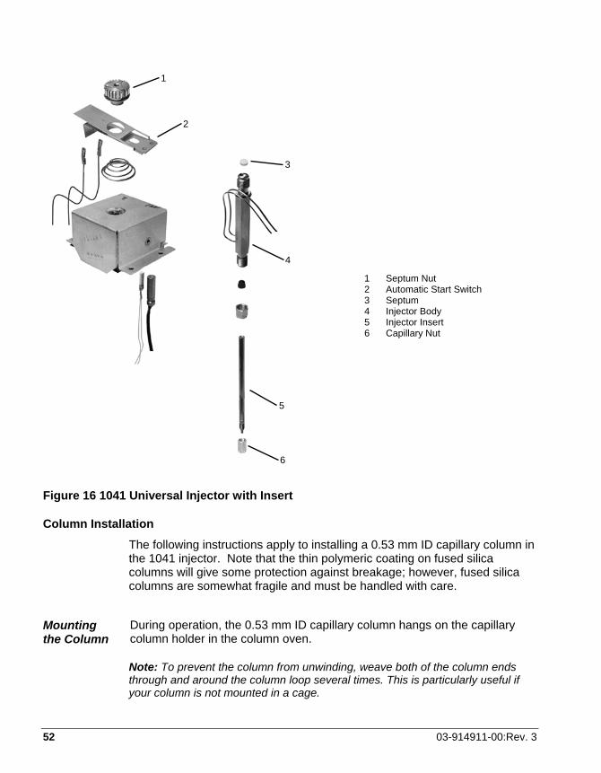
52 03-914911-00:Rev. 3
Figure 16 1041 Universal Injector with Insert
Column Installation The following instructions apply to installing a 0.53 mm ID capillary column in the 1041 injector. Note that the thin polymeric coating on fused silica columns will give some protection against breakage; however, fused silica columns are somewhat fragile and must be handled with care.
Mounting the Column
During operation, the 0.53 mm ID capillary column hangs on the capillary column holder in the column oven.
Note: To prevent the column from unwinding, weave both of the column ends through and around the column loop several times. This is particularly useful if your column is not mounted in a cage.
1 Septum Nut 2 Automatic Start Switch 3 Septum 4 Injector Body 5 Injector Insert 6 Capillary Nut
1
2
3
4
5
6
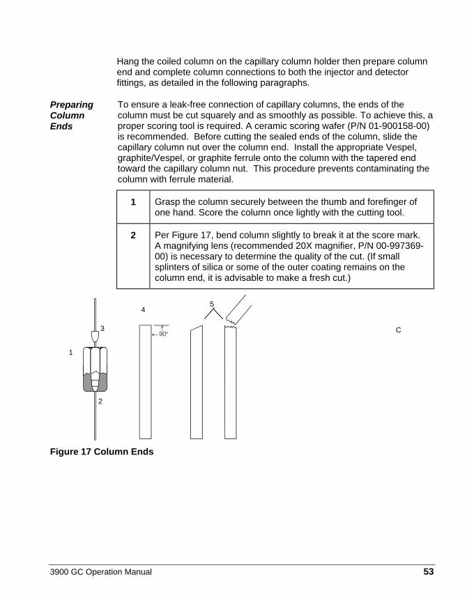
3900 GC Operation Manual 53
Hang the coiled column on the capillary column holder then prepare column end and complete column connections to both the injector and detector fittings, as detailed in the following paragraphs.
Preparing Column Ends
To ensure a leak-free connection of capillary columns, the ends of the column must be cut squarely and as smoothly as possible. To achieve this, a proper scoring tool is required. A ceramic scoring wafer (P/N 01-900158-00) is recommended. Before cutting the sealed ends of the column, slide the capillary column nut over the column end. Install the appropriate Vespel, graphite/Vespel, or graphite ferrule onto the column with the tapered end toward the capillary column nut. This procedure prevents contaminating the column with ferrule material.
1 Grasp the column securely between the thumb and forefinger of one hand. Score the column once lightly with the cutting tool.
2 Per Figure 17, bend column slightly to break it at the score mark. A magnifying lens (recommended 20X magnifier, P/N 00-997369-00) is necessary to determine the quality of the cut. (If small splinters of silica or some of the outer coating remains on the column end, it is advisable to make a fresh cut.)
Figure 17 Column Ends
C3
1
4 5
2

54 03-914911-00:Rev. 3
Table 4 General Tightening and Retightening for Common Ferrules Ferrule Type Recommendation Comments New graphite ferrule 1/4-turn past finger-tight 1/4- to 1/2-turn past finger-tight
may be required to achieve a seal.
Used graphite ferrule 1/4-turn past finger-tight If a different size of column is used, more tightening may be required.
New polyimide/graphite ferrule
1/4- to 1/2-turn past finger-tight May require retightening after first or second programmed run. Over tightening will destroy ferrule and seal.
Used polyimide/graphite ferrule
1/4-turn past finger-tight Re-use only on same size column.
New polyimide ferrule Not recommended with 1041 Used polyimide ferrule Not recommended with 1041
CAUTION
Column Connection to Injector
IMPORTANT ALIGNMENT OF THE CAPILLARY COLUMN: When a 0.53 mm ID capillary column is used in combination with the Varian 1041 injector, alignment of the column is critical. Use the following steps to precisely align the capillary column. Unless this procedure is followed, the injection syringe may damage the top of the column or peak tailing may result.
3900 GC Operation Manual 55
1 Install the capillary injector insert nut and the reversed ferrule on the column.
2 Uncoil about 20 cm of the injector end of the column. 3 Gently push the column fully up into the injector (approximately 3.5
inches), until the column comes to a firm stop. This correctly positions the column against the upper end of the injector insert. The column must go in the full distance. If it does not, the injector will not function properly. Tighten the column nut just enough to prevent column movement.
4 Manually insert the syringe that will be used with the column into the 1041 injector, checking that the syringe goes into the injector completely with no binding or interference. If interference occurs, repeat the above column insertion procedure until the syringe moves smoothly into the injector.
5 Continue to hold the column firmly in place as you tighten the column nut carefully and only enough to hold the column firmly in place and obtain a good seal. Remove the syringe from the injector.
6 After the column is installed at the injector end, make several dry injections to ensure that the needle enters the column easily.
7 Refer to the Detector section of this manual for column connection to the installed detector.
Setting the Carrier Gas Flow
The 1041 injector is supplied with Electronic Flow Control. Type 4 EFC is used with the 1041.
With type 4 Electronic Flow Control equipped injectors a flow range of 0 – 100 mL/min may be set from the 3900 keyboard. Press the Injector key and select the desired pressure and total flow rate. Both the pressure and total flow are programmable, use the insert line and delete line to build the tables as desired and then edit the entries as needed.
Flow Rates for Operation
Recommended flow rates differ, depending on the column.
Capillary Mode
When operating the injector in the capillary mode, the following carrier gas flow rates are recommended:
56 03-914911-00:Rev. 3
Table 5 Carrier Gas Flow Rates for 1041 Carrier Gas Column Flow Rate
(Optimum) Column Flow Rate (Typical)
Nitrogen 1.5 mL/min 3 - 15 mL/min Helium 2.4-4.0 mL/min 4 - 15 mL/min Hydrogen 4.0-8.0 mL/min 8 - 20 mL/min
Adjust the make-up gas flow to give a total of 30 mL/min.
Packed Mode
When operating in the packed column mode, adjust the carrier gas flow to applicable packed column flow rates (20 to 50 mL/min).
Testing the 1041 Injector The most effective method of testing injector performance is by running a test sample. The following procedure describes how to test the performance of the 1041 on column injector. This is best done with a test sample containing an appropriate set of components for the installed detector. The following table lists the series of test samples available for Varian GC detectors.
Note: Due to airline regulations, test samples are not shipped outside the USA. Refer to the compound concentrations in the table below to make your own test samples.
Table 6 1041 Test Compounds Test Sample Part Number Concentrations of Test Compounds TCD 82-005048-01 3.00 µg/µL of C14, C15, and C16 in iso-octane. FID 82-005048-07 30 ng/µL of C14, C15, and C16 in iso-octane. Note: If the FID test sample is not available, the TCD test sample can be used if first diluted 100:1.
To run the test sample use the default method for one of the methods in the 3900 GC. These conditions will give you optimum sensitivity and precision.

3900 GC Operation Manual 57
Detector Connections and Hardware The 3900 GC uses either a flame ionization detector (FID) or a thermal conductivity detector (TCD) to detect compounds in the effluent of the column. Both are installed at the factory; to begin using your 3900 GC you simply need to connect the following gas supplies (see FID section or TCD section as it relates to your GC):
Make-up (typically the same gas as the carrier gas) set to at least 80 psi and no more than 100 psi. Hydrogen set to 40 psi. Air set to 60 psi.
The default settings in the 3900 GC for the make-up (25 mL/min), hydrogen (30 mL/min), and air (300 mL/min) are the recommended settings for those gases. If you do need to change these gas flow rates, simply press the Detector icon and press the Enter key until the gas flow rate you desire to change is displayed.
FID Connections
Figure 18 FID Cross-sectional View
Collector Tube (03-949587-00)
Signal Probe
Notch
Ignitor Probe
Insulator
Ignitor Coil
Spring Clip
Flame Tip Assembly
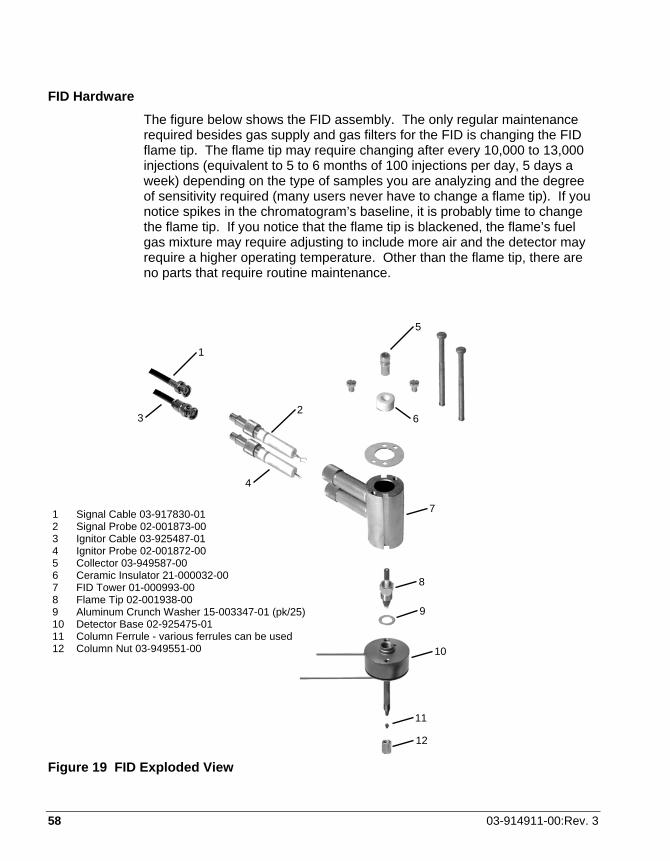
58 03-914911-00:Rev. 3
FID Hardware The figure below shows the FID assembly. The only regular maintenance required besides gas supply and gas filters for the FID is changing the FID flame tip. The flame tip may require changing after every 10,000 to 13,000 injections (equivalent to 5 to 6 months of 100 injections per day, 5 days a week) depending on the type of samples you are analyzing and the degree of sensitivity required (many users never have to change a flame tip). If you notice spikes in the chromatogram’s baseline, it is probably time to change the flame tip. If you notice that the flame tip is blackened, the flame’s fuel gas mixture may require adjusting to include more air and the detector may require a higher operating temperature. Other than the flame tip, there are no parts that require routine maintenance.
Figure 19 FID Exploded View
1
2
5
6 3
4
7
8
9
11
10
12
1 Signal Cable 03-917830-01 2 Signal Probe 02-001873-00 3 Ignitor Cable 03-925487-01 4 Ignitor Probe 02-001872-00 5 Collector 03-949587-00 6 Ceramic Insulator 21-000032-00 7 FID Tower 01-000993-00 8 Flame Tip 02-001938-00 9 Aluminum Crunch Washer 15-003347-01 (pk/25) 10 Detector Base 02-925475-01 11 Column Ferrule - various ferrules can be used 12 Column Nut 03-949551-00
3900 GC Operation Manual 59
Disassemble the FID
1. Set the FID to 50 °C and wait for it to cool before disassembly. Turn the detector electronics and detector oven OFF in the active method. Remove the GC top covers.
2. Turn off the main GC gas supplies to the detector at the pneumatics panel. These are the make-up, hydrogen and air supplies.
3. Disconnect the signal and ignitor cables from their probes on the detector tower.
4. Remove the signal and ignitor probes from the detector tower. DO NOT rotate the probes as you disconnect them from the electrical contacts in the tower. Place the probes on a clean surface such as a lint-free laboratory tissue.
5. Remove the two 8-32 x 2-3/4-inch tower mounting screws from the top of detector tower. The screws should be tightened to no more than 20 inch-pounds of torque
6. Remove the tower assembly from the detector oven, lifting straight up until clear of the flame tip. Remove the collector tube and insulator from the detector tower. Avoid contamination of the ceramic insulator and probes. If the detector is not completely cool, use a metal tool (such as tweezers or a hooked wire) to remove parts from the tower assembly. Place parts on a clean Kimwipe®. Never place them on a counter or painted surface.
7. Remove the flame-tip assembly from the detector base. Take care not to break the ceramic flame tip tube or the Vespel®/graphite or graphite ferrule.
8. Remove and discard the aluminum seal washer from the detector base. Always use a new aluminum seal washer each time you reassemble the detector. Note that the aluminum seal washer may remain in the detector tower when the tower is removed from the base.
60 03-914911-00:Rev. 3
Reassemble the FID
Refer to Figure 19 to reassemble the FID detector. To reassemble the FID, proceed as follows:
1. If you removed the detector base from the plenum, restore the base to its former position and reinstall the four screws holding the oven to the plenum.
2. Install the flame tip in the detector base.
• If you are installing the flame tip with a new Vespel/graphite ferrule, tighten the assembly finger-tight plus an extra 1/6-turn.
• If you are installing the flame tip assembly with a used graphite ferrule, tighten about 1/3-turn past finger-tight.
3. The Vespel/graphite ferrule supplied with the GC has a maximum temperature limit of 350 °C. If it is necessary to operate the detector above 350 °C, you may need to replace the Vespel/graphite ferrule with a graphite ferrule.
4. Install a new aluminum seal washer onto the shoulder of the detector base. To ensure a reliable tower seal, use a NEW aluminum washer each time you install the detector.
5. Place the detector tower on the detector base and secure it with the two 8-32 x 2-3/4-inch tower mounting screws; do not exceed 20 inch-pounds of torque! Alternately tighten these screws a 1/2-turn as the tower tightens into place following the torque specification above.
CAUTION
Handle the ceramic insulator and probes with tweezers to avoid contamination.
6. Carefully insert the ignitor probe into the lower arm of the detector tower. Align the probe key with the tower arm slot. Check the orientation of the ignitor elements by looking down through the top of the detector tower. The spring clip should slip around the flame tip and make good contact (see Figure 20). The ignitor coil must not touch the flame tip assembly nor be positioned directly above it. Tighten the knurled nut to secure the probe.
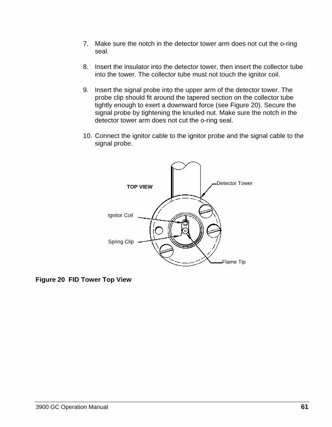
3900 GC Operation Manual 61
7. Make sure the notch in the detector tower arm does not cut the o-ring seal.
8. Insert the insulator into the detector tower, then insert the collector tube into the tower. The collector tube must not touch the ignitor coil.
9. Insert the signal probe into the upper arm of the detector tower. The probe clip should fit around the tapered section on the collector tube tightly enough to exert a downward force (see Figure 20). Secure the signal probe by tightening the knurled nut. Make sure the notch in the detector tower arm does not cut the o-ring seal.
10. Connect the ignitor cable to the ignitor probe and the signal cable to the signal probe.
Figure 20 FID Tower Top View
Detector Tower
Spring Clip
Ignitor Coil
TOP VIEW
Flame Tip
62 03-914911-00:Rev. 3
Thermal Conductivity Detector The Thermal Conductivity Detector (TCD) is mounted directly above the column oven on the 3900 GC. The TCD PC Board is installed in the electronics cabinet on the right side of the instrument.
TCD operating parameters are set at the 3900 keyboard: These include carrier gas type, detector temperature, range, temperature limit, and filament temperature. Carrier gas flow is set and controlled electronically by EFC.
Initial Set-Up To set up the TCD, proceed as follows. Note that the TCD is a two channel detector and requires both a sample flow of carrier gas and a reference flow of the same gas. Either channel can be used as the sample stream but there must always be a reference stream.
1 Connect the gas lines to the appropriate bulkhead fittings on the GC.
2 Check the gas supply pressures. Set at 80 psig.
3 Establish carrier gas flow through the Sample (right) side of the TCD and an equal Reference gas flow through the Reference (left) side of the detector. If you are using a capillary column, the total of column flow and makeup flow should equal the Reference gas flow. Perform a Leak Check on both the Sample and Reference pneumatics before proceeding to apply power to the TCD filaments. Even a small leak can supply enough oxygen to cause filament oxidation and consequent baseline drift. Select Setup then EFC and set the gas type to He, H2, or N2 based on the selected gas type. The TCD is equipped with Detector EFC. The carrier gas and detector EFC gas selections must be the same type. Select the Detector Icon and set TCD carrier gas to He/H2 for Helium or Hydrogen. For all other carrier gases, select the N2/Ar setting.
TCD Adjustments Select Setup and set EFC Gas Type to the same type.
Setting the Filament Temperature Limit
1 To protect the filament, always operate the detector with the 390°C limit selected unless you require the maximum dynamic range available to the TCD.
With prolonged use, the filaments slowly oxidize and their resistances increase. At some point this will cause the largest peaks in your chromatogram to become flat topped, indicating that the filament protection software has been activated. (Note that if the TCD signal is sufficiently large the output may go to zero and become unresponsive. If this occurs, adjust your injection site and conditions to avoid over range conditions.)
3900 GC Operation Manual 63
To adjust for this increase in resistance, set the Filament Temperature Limit to 490 °C, even for filament temperature setpoints below 390 °C.
The TCD filament is automatically protected in the GC. The GC turns off the filament current after four minutes if it detects that the carrier gas flow has stopped or that the filament current is low. Also, the GC turns off filament current when it detects that carrier gas is flowing through one side of the detector cell but not through the other (e.g., a septum or column is not installed, or a leak exists in one cell and not the other).
If you select Helium or H2 as the carrier gas, the GC operates in the standard way to protect the TCD filament. However, because the filament protection feature in the GC operates through the detection of air (or N2) in the detector cells, the filament protection feature is disabled when you use nitrogen or argon as the carrier gas.
Set the Filament Temperature Limit to 390 °C or 490 °C, according to the highest filament temperature setpoint required. With the Limit set to 390 °C, the peak sample filament temperature is limited to approximately 450 °C. The temperature limit is approximately 550 °C at the 490 °C setting. The 450 °C limit protects filaments from oxidation when exposed to air over an extended period of time. However, at the 550 °C temperature limit the filament can degrade after only a few minutes.
CAUTION
If you select N2/Ar as the carrier gas, the filament protection feature is disabled. Because the GC does not turn off the filament current, the TCD filaments can rapidly oxidize if you operate the TCD filament temperature above 390 °C without carrier gas flowing through the TCD cells. If you plan to operate the TCD after the carrier gas has been turned off, purge the air from the TCD cells with carrier gas for five minutes before operating the TCD.
Operation To operate, the TCD requires only carrier gas. Helium or hydrogen are recommended as carrier gases. You can use nitrogen as a carrier gas, but you may lose some sensitivity and see an increase in the detector noise.
WARNING:FIRE HAZARD
If hydrogen is used as a carrier gas, vent the hydrogen from the TCD to a safe place. Hydrogen is very flammable.
64 03-914911-00:Rev. 3
Before Operating the TCD
Do not operate the TCD until you have connected carrier gas to both inlets of the TCD. The TCD accommodates two columns (a column for the reference cell and a column for the detector cell) or a column and a reference line. The columns can be packed or capillary columns and you can combine a capillary column with a packed column. To avoid contaminating the detector, condition all packed columns before you connect them to the TCD.
For the following discussion, assume that the analytical column is attached to the right side of the TCD and the reference column or reference gas supply to the left side of the TCD. However, you can configure the GC with the analytical column connected to the left side of the TCD, simply reverse the TCD polarity.
Note: If you plan to operate the TCD after the carrier gas has been turned off for an extended period of time, turn on the carrier gas for five minutes before turning on the filament current to purge air from the system. This prevents oxidation of the TCD filaments.
At the factory, the carrier gas flow rate for TCD is set at 30 mL/min. (Carrier gas: He) through both sides of the detector. The carrier gas flow rate is measured at the two exit ports on the TCD. Once the carrier gas is flowing through the TCD, set up the TCD for operation as follows:
1 Set the TCD oven to the desired temperature and allow it to come to the setpoint. Usually, set the TCD temperature at least 20°C higher than the maximum temperature the column oven reaches in your analysis.
2 Set TCD filament temperature in the detector section. A filament temperature 50°C above the detector temperature should provide a good starting point for most applications. Turn the TCD Electronics ON to begin heating the filaments.
3 Allow system to equilibrate 10 to 15 minutes.
4 Monitor the filament current through the detector status display. Initially, the current is greater than the final operating current. Gradually, however, the current decreases as the detector thermally equilibrates. For best performance of the detector, do not permit the filament temperature to exceed the detector temperature by more than 200 °C. Generally, use the lowest detector current possible for the sensitivity your application requires.
5 Set the initial Autozero to OFF. Set Autozero to NO, then select the Command icon followed by Autozero Now. Monitor the signal on the detector status display. A continuous drift, either positive or negative, may indicate an air leak in either the carrier or reference gas stream.
6 Note that it is normal for the TCD baseline to drift until the detector thermally equilibrates. The time it takes to reach equilibrium always exceeds the time it takes for the detector oven to reach its temperature. When the baseline is stable, you can begin your analysis. Autozero is automatically disabled when the GC method is in RUN.

3900 GC Operation Manual 65
Change Initial Autozero back to YES. This allows the system to balance the bridge automatically before each run for maximum dynamic range. The current status of the balance control, from -99% to +99%, is shown on the display.
A continuous drift in the balance value over time may indicate you have an air leak which is causing one set of filaments to oxidize, changing their resistance and unbalancing the detector bridge.
Range Setting
Use the 0.05 mV range in the following cases:
• Low currents (100-150 mA) • High Currents (300 mA) • Output Signal Fed to Computer or Integrator
Low Currents (100-150 mA)
Analyses that had required a high filament current and a less sensitive range can often be performed at lower currents and a more sensitive range. For example, a filament current of 120 mA and a range of 0.05 mV yields about the same output signal as a filament current of 300 mA and a range of 0.5 mV. At the lower current, the detector noise is lower, the stability is higher, and the filament lifetime is extended. Thus, Varian recommends that, whenever possible, you operate the TCD at the lowest practical filament current.
The chromatograms in Figure 21 illustrate the high sensitivity and detectivity (18 ppm of Neon in air) that is possible with the TC Detector. Also, a comparison of chromatogram A with chromatogram B shows that with the use of the bridge output signal amplifier, you can obtain the same analytical results at half the filament current, thereby extending the lifetime of the TCD filament. The Neon peak in chromatogram C illustrates how you can use a high filament current (300 mA) with a high amplification setting to increase the effective sensitivity of the TCD.
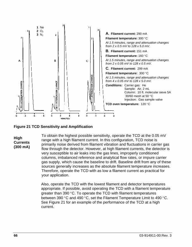
66 03-914911-00:Rev. 3
Figure 21 TCD Sensitivity and Amplification
High Currents (300 mA)
To obtain the highest possible sensitivity, operate the TCD at the 0.05 mV range with a high filament current. In this configuration, TCD noise is primarily noise derived from filament vibration and fluctuations in carrier gas flow through the detector. However, at high filament currents, the detector is very susceptible to air leaks into the gas lines, improperly conditioned columns, imbalanced reference and analytical flow rates, or impure carrier gas supply, which cause the baseline to drift. Baseline drift from any of these sources generally increases as the absolute filament temperature increases. Therefore, operate the TCD with as low a filament current as practical for your application.
Also, operate the TCD with the lowest filament and detector temperatures appropriate. If possible, avoid operating the TCD with a filament temperature greater than 390 °C. To operate the TCD with filament temperatures between 390 °C and 490 °C, set the Filament Temperature Limit to 490 °C. See Figure 21 for an example of the performance of the TCD at a high current.
A. Filament current: 290 mA Filament temperature: 300 °C At 1.5 minutes, range and attenuation changes from 2 x 0.5 mV to 128 x 5.0 mV. B. Filament current: 151 mA Filament temperature: 160 °C At 1.5 minutes, range and attenuation changes from 2 x 0.05 mV to 128 x 0.5 mV. C. Filament current: 299 mA Filament temperature: 300 °C At 1.5 minutes, range and attenuation changes from 4 x 0.05 mV to 128 x 5.0 mV. Conditions: Carrier gas: He Sample: Air, 2 mL Column: 10 ft. molecular sieve 5A 30/60 mesh at 50 °C Injection: Gas sample valve TCD oven temperature: 120 °C
1 Ne 2 O2 3 N2

3900 GC Operation Manual 67
Calculate Detector Sensitivity
To calculate the sensitivity of the TCD, proceed as follows:
EXAMPLE 1: Known Sample Weight S = PFC/W
Where: S = Sensitivity in mV x mL/mg P = Integrated peak area in mV x min W = Weight of sample in carrier gas in mg
FC = Carrier gas flow in mL/min corrected to detector temp FC = FO (TD/TA)(1-PW/PA)
Where: FO = Flow rate measured at detector outlet (at ambient temperature) in mL/min. TD = Detector temperature in °K TA = Ambient temperature in °K PW = Partial pressure of H2O at ambient temperature in torr PA = Ambient pressure in torr
Note: The (1-PW /PA) expression applies only if using a bubble flowmeter.
EXAMPLE 2: Known Concentration of Sample in Detector S = E/CD
Where: S = Sensitivity in mV x mL/mg E = Detector signal (peak height) in mV CD = Concentration of test substance in the measured peak volume in mg/mL
Peak volume = Peak width at half height (in min.) x gas flow rate at detector (in mL/min) = W • h/2 x FC
Calculate Detector Detectivity
To calculate the detectivity of the TCD, proceed as follows:
Detectivity 2 x NoiseSensitivity=
68 03-914911-00:Rev. 3
Reverse Polarity
If you inject a standard or sample into the reference side of the TCD, peaks appear in the negative direction. If you want to integrate or process these peaks with a data system, you must convert the polarity of the peaks from negative to positive. Reference the TCD section to set initial detector polarity either Positive or Negative.
You can also time program when you would like the polarity to be automatically reversed during a chromatographic run. Set a time-programmed polarity reversal in the detector method section.
Adjust TCD Carrier Gas Flow Rates All 3900 GCs equipped with TCDs are factory tested at the flow rate listed below. Adjustments to the carrier gas flow rate are made using the Injector icon for column flow and Detector icon for makeup and/or reference flow.
Carrier Gas: Helium Inlet Pressure: 80 psig Purity: 99.999% Column Flow Rate: 30 mL/min Reference Column Flow Rate: 30 mL/min
Note: Tightly cap gas filters when not used. Prolonged exposure of the contents of the filter to room air degrades the performance of the filters.
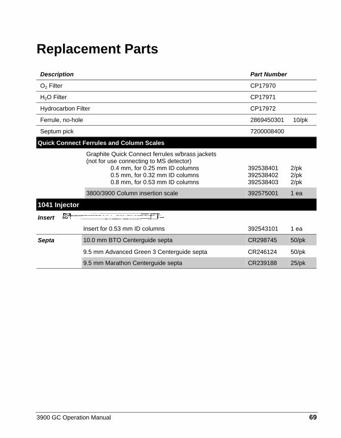
3900 GC Operation Manual 69
Replacement Parts Description Part Number
O2 Filter CP17970
H2O Filter CP17971
Hydrocarbon Filter CP17972
Ferrule, no-hole 2869450301 10/pk
Septum pick 7200008400
Quick Connect Ferrules and Column Scales
Graphite Quick Connect ferrules w/brass jackets (not for use connecting to MS detector) 0.4 mm, for 0.25 mm ID columns 0.5 mm, for 0.32 mm ID columns 0.8 mm, for 0.53 mm ID columns
392538401 392538402 392538403
2/pk 2/pk 2/pk
3800/3900 Column insertion scale 392575001 1 ea
1041 Injector
Insert
Insert for 0.53 mm ID columns 392543101 1 ea
10.0 mm BTO Centerguide septa CR298745 50/pk Septa
9.5 mm Advanced Green 3 Centerguide septa CR246124 50/pk
9.5 mm Marathon Centerguide septa CR239188 25/pk
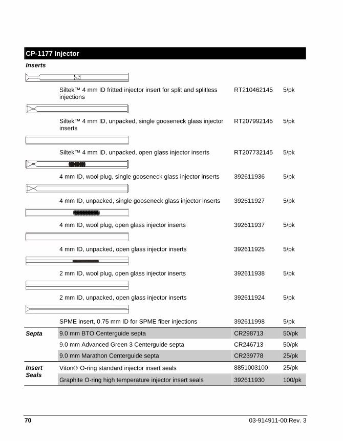
70 03-914911-00:Rev. 3
CP-1177 Injector Inserts
Siltek™ 4 mm ID fritted injector insert for split and splitless
injections RT210462145 5/pk
Siltek™ 4 mm ID, unpacked, single gooseneck glass injector
inserts RT207992145 5/pk
Siltek™ 4 mm ID, unpacked, open glass injector inserts RT207732145 5/pk
4 mm ID, wool plug, single gooseneck glass injector inserts 392611936 5/pk
4 mm ID, unpacked, single gooseneck glass injector inserts 392611927 5/pk
4 mm ID, wool plug, open glass injector inserts 392611937 5/pk
4 mm ID, unpacked, open glass injector inserts 392611925 5/pk
2 mm ID, wool plug, open glass injector inserts 392611938 5/pk
2 mm ID, unpacked, open glass injector inserts 392611924 5/pk
SPME insert, 0.75 mm ID for SPME fiber injections 392611998 5/pk
9.0 mm BTO Centerguide septa CR298713 50/pk
9.0 mm Advanced Green 3 Centerguide septa CR246713 50/pk
Septa
9.0 mm Marathon Centerguide septa CR239778 25/pk
Viton O-ring standard injector insert seals 8851003100 25/pk Insert Seals
Graphite O-ring high temperature injector insert seals 392611930 100/pk

3900 GC Operation Manual 71
Faults
The 3900 GC has a Fault LED on the bottom panel next to the Power LED. If you have a 3900 GC equipped with a LUI, you will also have a fault LED located on the upper right area of the keypad. The fault LED on the lower panel will illuminate when there is a fault that is considered fatal (a hard fault). A fatal fault can not be cleared by any user action other than turning off the GC and then turning it back on. The fault LED on the keypad illuminates for any type fault. If the fault LED on the keypad is illuminated and the one on the lower panel is not (this is a soft fault), you can clear the fault by removing its cause and activating a method or beginning Automation in most cases.
Message Fault Type Explanation/Remedy
+5V OUT OF RANGE Fatal Turn off instrument and turn it back on. If the fault recurs, call your Varian Service Representative.
-5V OUT OF RANGE Fatal The –5V power line is outside of its allowed tolerance for correct GC operation. Turn the power off and then on again. If the problem persists, call your Varian Service Representative.
A/S # STROKES > LIMIT Soft This is an advisory message that the plunger stroke count has exceeded the limit that was set for it. You should change the syringe and zero the plunger stroke counter soon after you observe this message.
A/S CAR SENSOR ERROR Fatal The AutoSampler carrousel sensor has failed to conform to its expected operation. Turn off the GC and then on again. If the problem persists, call your Varian Service Representative.
A/S CARROUSEL ERROR Fatal The A/S carrousel base has encountered one or more internal faults and has failed to properly come up. Turn off the power and then turn it back on. If the problem recurs, call your Varian Service Representative.
A/S COMM ERROR Fatal The AutoSampler/AutoInjector has experienced an error during communications that was unrecoverable. Power off both your GC and the AutoSampler, Turn on power to the GC followed by turning on the power to the AutoSampler. If the problem persists, call your Varian Service Representative.
A/S FAILURE Fatal The A/S has failed to properly come up. Turn off the power and then turn it back on. If the problem recurs, call your Varian Service Representative.
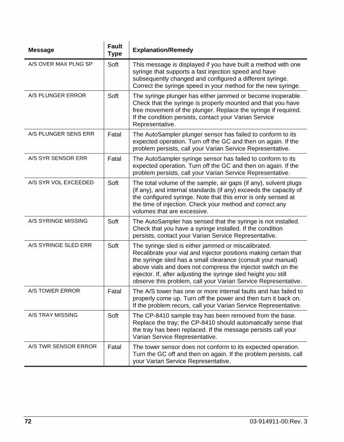
72 03-914911-00:Rev. 3
Message Fault Type Explanation/Remedy
A/S OVER MAX PLNG SP Soft This message is displayed if you have built a method with one syringe that supports a fast injection speed and have subsequently changed and configured a different syringe. Correct the syringe speed in your method for the new syringe.
A/S PLUNGER ERROR Soft The syringe plunger has either jammed or become inoperable. Check that the syringe is properly mounted and that you have free movement of the plunger. Replace the syringe if required. If the condition persists, contact your Varian Service Representative.
A/S PLUNGER SENS ERR Fatal The AutoSampler plunger sensor has failed to conform to its expected operation. Turn off the GC and then on again. If the problem persists, call your Varian Service Representative.
A/S SYR SENSOR ERR Fatal The AutoSampler syringe sensor has failed to conform to its expected operation. Turn off the GC and then on again. If the problem persists, call your Varian Service Representative.
A/S SYR VOL EXCEEDED Soft The total volume of the sample, air gaps (if any), solvent plugs (if any), and internal standards (if any) exceeds the capacity of the configured syringe. Note that this error is only sensed at the time of injection. Check your method and correct any volumes that are excessive.
A/S SYRINGE MISSING Soft The AutoSampler has sensed that the syringe is not installed. Check that you have a syringe installed. If the condition persists, contact your Varian Service Representative.
A/S SYRINGE SLED ERR Soft The syringe sled is either jammed or miscalibrated. Recalibrate your vial and injector positions making certain that the syringe sled has a small clearance (consult your manual) above vials and does not compress the injector switch on the injector. If, after adjusting the syringe sled height you still observe this problem, call your Varian Service Representative.
A/S TOWER ERROR Fatal The A/S tower has one or more internal faults and has failed to properly come up. Turn off the power and then turn it back on. If the problem recurs, call your Varian Service Representative.
A/S TRAY MISSING Soft The CP-8410 sample tray has been removed from the base. Replace the tray; the CP-8410 should automatically sense that the tray has been replaced. If the message persists call your Varian Service Representative.
A/S TWR SENSOR ERROR Fatal The tower sensor does not conform to its expected operation. Turn the GC off and then on again. If the problem persists, call your Varian Service Representative.

3900 GC Operation Manual 73
Message Fault Type Explanation/Remedy
A/S VIAL MISSING Soft The AutoSampler has failed to detect a vial within an expected range of vials. This message is an advisory message. If you have a vial in the position and it has been missed, check that a septum is installed. Lack of a septum and dark colors may cause the tower sensor to fail to identify the vial.
A/S VIAL SENSOR ERR Fatal The AutoSampler vial sensor has failed to conform to its expected operation. Turn off the GC and then on again. If the problem persists, call your Varian Service Representative.
A/S VIAL UNREACHABLE Soft This message informs you that the CP-8410 tray is oriented such that the requested sample vial does not fall under the arc of the tower. Re-orient the tray or change the requested vial from which you intend to inject to correct this.
ADC CALIB FAILURE Fatal The DAC (Digital to Analog Converter) that supplies the analog output signal failed to calibrate within its set tolerance. Turn off the power and then turn it back on. If the problem is observed again either immediately or within a short period of time call your Varian Service Representative.
COL RESPNSE TOO FAST Fatal Turn off instrument and turn it back on. If the fault recurs, call your Varian Service Representative.
COL RESPNSE TOO SLOW Fatal Turn off instrument and turn it back on. If the fault recurs, call your Varian Service Representative.
COL TEMP PROBE OPEN Fatal Turn off instrument and turn it back on. If the fault recurs, call your Varian Service Representative.
COL TEMP PROBE SHORT Fatal Turn off instrument and turn it back on. If the fault recurs, call your Varian Service Representative.
COL TEMP TOO LOW Fatal Turn off instrument and turn it back on. If the fault recurs, call your Varian Service Representative
COL THERMAL RUNAWAY Fatal Turn off instrument and turn it back on. If the fault recurs, call your Varian Service Representative.
DAC CALIB FAILURE Soft Activate a method to clear this fault. If the fault recurs, turn the GC off and then on. If the fault persists, call your Varian Service Representative.
DET RESPNSE TOO FAST Fatal Turn off instrument and turn it back on. If the fault recurs, call your Varian Service Representative.
DET RESPNSE TOO SLOW Fatal Turn off instrument and turn it back on. If the fault recurs, call your Varian Service Representative.
DET TEMP PROBE OPEN Fatal Turn off instrument and turn it back on. If the fault recurs, call your Varian Service Representative.
DET TEMP PROBE SHORT Fatal Turn off instrument and turn it back on. If the fault recurs, call your Varian Service Representative.

74 03-914911-00:Rev. 3
Message Fault Type Explanation/Remedy
DET TEMP TOO LOW Fatal The detector oven temperature is below the allowed temperature. Turn the GC off and then on again. If the problem persists, call your Varian Service Representative.
DIAG TEMP ERROR Fatal The actual temperature of a temperature controlled resistor block used for automatic instrument calibration has exceeded its allowed temperature set point. Turn the power to the GC off and then on again. If the problem persists, call your Varian Service Representative.
FAN UNPLUGGED IN RUN Fatal Turn off instrument and turn it back on. If the fault recurs, call your Varian Service Representative.
FID FLAME OUT Soft The FID flame has been quenched. The flame detection is based on a background signal intensity of approximately 330 microvolts. It is possible for very clean GC systems to have baselines less than 330 microvolts causing spurious flameout messages. If you suspect that the flameout message is spurious, use a shiny, cool metal object (such as a box end wrench) and hold it just above the FID tower being careful not to get too close to the hot surfaces. If you observe condensation then the flame is still lit; you may wish to change your fuel gas mixture or some other operating characteristic that would allow a slightly higher background signal. Once a flame out is detected, the system will attempt to ignite the flame 3 times before reporting the flame out condition. The fault is cleared by either igniting the flame using the Ignite FID Flame! Command or by turning the Detector electronics off.
FLOW > MAX DEFC FLOW Fatal Turn off instrument and turn it back on. If the fault recurs, call your Varian Service Representative.
GAS SAVER TIMEOUT Soft The GC has been idle for a period of time equal to or greater than the set Gas Saver timeout period. Activate a method to clear the fault.
INJ RESPNSE TOO FAST Fatal Turn off instrument and turn it back on. If the fault recurs, call your Varian Service Representative.
INJ RESPNSE TOO SLOW Fatal Turn off instrument and turn it back on. If the fault recurs, call your Varian Service Representative.
INJ TEMP PROBE OPEN Fatal Turn off instrument and turn it back on. If the fault recurs, call your Varian Service Representative.
INJ TEMP PROBE SHORT Fatal Turn off instrument and turn it back on. If the fault recurs, call your Varian Service Representative.
INJ TEMP TOO LOW Fatal Turn off instrument and turn it back on. If the fault recurs, call your Varian Service Representative.
INJ THERMAL RUNAWAY Fatal Turn off instrument and turn it back on. If the fault recurs, call your Varian Service Representative.
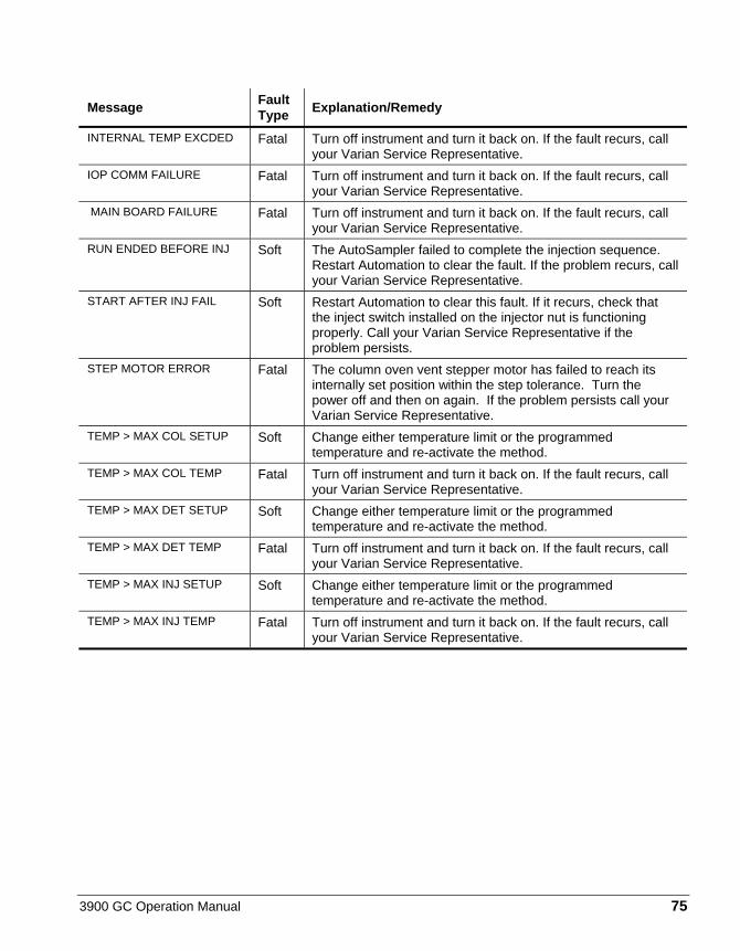
3900 GC Operation Manual 75
Message Fault Type Explanation/Remedy
INTERNAL TEMP EXCDED Fatal Turn off instrument and turn it back on. If the fault recurs, call your Varian Service Representative.
IOP COMM FAILURE Fatal Turn off instrument and turn it back on. If the fault recurs, call your Varian Service Representative.
MAIN BOARD FAILURE Fatal Turn off instrument and turn it back on. If the fault recurs, call your Varian Service Representative.
RUN ENDED BEFORE INJ Soft The AutoSampler failed to complete the injection sequence. Restart Automation to clear the fault. If the problem recurs, call your Varian Service Representative.
START AFTER INJ FAIL Soft Restart Automation to clear this fault. If it recurs, check that the inject switch installed on the injector nut is functioning properly. Call your Varian Service Representative if the problem persists.
STEP MOTOR ERROR Fatal The column oven vent stepper motor has failed to reach its internally set position within the step tolerance. Turn the power off and then on again. If the problem persists call your Varian Service Representative.
TEMP > MAX COL SETUP Soft Change either temperature limit or the programmed temperature and re-activate the method.
TEMP > MAX COL TEMP Fatal Turn off instrument and turn it back on. If the fault recurs, call your Varian Service Representative.
TEMP > MAX DET SETUP Soft Change either temperature limit or the programmed temperature and re-activate the method.
TEMP > MAX DET TEMP Fatal Turn off instrument and turn it back on. If the fault recurs, call your Varian Service Representative.
TEMP > MAX INJ SETUP Soft Change either temperature limit or the programmed temperature and re-activate the method.
TEMP > MAX INJ TEMP Fatal Turn off instrument and turn it back on. If the fault recurs, call your Varian Service Representative.