![New t New CUBEs with Heavy Attitude t - American Musical Supply · 2013. 11. 26. · METAL ZONE, EXTREME), GAIN Knob, VOLUME Knob, [EQUALIZER] BASS Knob, MIDDLE Knob, TREBLE Knob](https://static.fdocuments.in/doc/165x107/6067859789f730682b1d8a47/new-t-new-cubes-with-heavy-attitude-t-american-musical-supply-2013-11-26.jpg)
384 MANUAL BEDKNIFE GRINDER - Grinder Equipment, Golf ...foleyunited.com/Uploads//3847953 -...
21
This book consists of two manuals: The OPERATORS MANUAL which contains all the information on operating and doing routine daily maintenance on this equipment. The ASSEMBLY and SERVICE MANUAL which is used by the maintainence department to install the equipment and to do all maintenance except routine daily maintenance. Setting the Standard With the World's Most Valued Grinders. 384 MANUAL BEDKNIFE GRINDER
Transcript of 384 MANUAL BEDKNIFE GRINDER - Grinder Equipment, Golf ...foleyunited.com/Uploads//3847953 -...
1
This book consists of two manuals:
The OPERATORS MANUAL which contains all theinformation on operating and doing routine dailymaintenance on this equipment.
The ASSEMBLY and SERVICE MANUAL which isused by the maintainence department to install theequipment and to do all maintenance except routinedaily maintenance.
Setting the Standard With theWorld's Most Valued Grinders.
384MANUAL
BEDKNIFE GRINDER

2
W e are committed to:
Providing superior customer support, training,and service.
Manufacturing the highest quality products at anunequaled value.
Setting the industry standard by investing intechnological product innovation.
Manufacturing products specifically designed tomaintain original equipment manufacturers'specifications.
Interacting with and supporting all originalequipment manufacturers.
Setting the Standard With the World's Most Valued Grinders.

3
384MANUAL
BEDKNIFE GRINDER
OPERATORSMANUAL
3847953 (7-03)
WARNINGYou must thoroughly read and understand this manualbefore operating the equipment, paying particularattention to the Warning & Safety instructions.

4
SAFETY INSTRUCTIONS
Safety Awareness Symbols are inserted into thismanual to alert you to possible Safety Hazards . When-ever you see these symbols, follow their instructions.
The Warning Symbol identifies special instructionsor procedures which, if not correctly followed, couldresult in personal injury.
The Caution Symbol identifies special instructionsor procedures which, if not strictly observed, couldresult in damage to or destruction of equipment.
1. KEEP GUARDS IN PLACE and in workingorder.
2. REMOVE WRENCHES AND OTHER TOOLS.
3. KEEP WORK AREA CLEAN.
4. DON'T USE IN DANGEROUS ENVIRONMENT.Don't use Grinder in damp or wet locations.Grinder is for indoor use only. Keep work areawell lit.
5. KEEP ALL VISITORS AWAY . All visitorsshould be kept a safe distance from work area.
6. MAKE WORK AREA CHILD-PROOF withpadlocks or master switches.
7. DON'T FORCE THE GRINDER. It will do the jobbetter and safer if used as specified in thismanual.
8. USE THE RIGHT TOOL. Don't force the Grinderor an attachment to do a job for which it was notdesigned.
9. WEAR PROPER APPAREL. Wear no looseclothing, gloves, neckties, or jewelry which mayget caught in moving parts. Nonslip footwear isrecommended. Wear protective hair covering tocontain long hair.
10. ALWAYS USE SAFETY GLASSES .
11. SECURE YOUR WORK. Make certain that thebedknife is securely fastened with the clampsprovided before operating.
12. DON'T OVERREACH. Keep proper footing andbalance at all times.
13. MAINTAIN GRINDER WITH CARE. Followinstructions in Assembly and Service Manual for
lubrication and preventive maintenance.
14. DISCONNECT POWER BEFORE SERVICING,or when changing the grinding wheel.
15. REDUCE THE RISK OF UNINTENTIONALSTARTING. Make sure the switch is OFFbefore plugging in the Grinder.
16. USE RECOMMENDED ACCESSORIES.Consult the manual for recommendedaccessories. Using improper accessories maycause risk of personal injury.
17. CHECK DAMAGED PARTS. A guard or otherpart that is damaged or will not perform itsintended function should be properly repairedor replaced.
18. NEVER LEAVE GRINDER RUNNINGUNATTENED. TURN POWER OFF. Do notleave grinder until it comes to a complete stop.
19. KNOW YOUR EQUIPMENT. Read this manualcarefully. Learn its application and limitations aswell as specific potential hazards.
20. KEEP ALL SAFETY DECALS CLEAN ANDLEGIBLE. If safety decals become damaged orillegible for any reason, replace immediately.Refer to replacement parts illustrations inAssembly & Service Manual for the properlocation and part numbers of safety decals.
21. DO NOT OPERATE THE GRINDER WHENUNDER THE INFLUENCE OF DRUGS,ALCOHOL, OR MEDICATION

5
AVOID INHALATION OF DUST generated by grinding and cutting operations.Exposure to dust may cause respiratory ailments. Use approved NIOSH orMSHA respirators, safety glasses or face shields, and protective clothing.Provide adequate ventilation to eliminate dust, or to maintain dust level belowthe Threshold. Limit Value for nuisance dust as classified by OSHA.
SAFETY INSTRUCTIONS
IMPROPER USE OF GRINDING WHEEL MAYCAUSE BREAKAGE AND SERIOUS INJURY.
Grinding is a safe operation if the few basic rules listed below are followed. Theserules are based on material contained in the ANSI B7.1 Safety Code for "Use, Careand Protection of Abrasive Wheels". For your safety, we suggest you benefit fromthe experience of others and carefully follow these rules.
DO
1. DO always HANDLE AND STORE wheels in aCAREFUL manner.
2. DO VISUALLY INSPECT all wheels beforemounting for possible damage.
3. DO CHECK MACHINE SPEED against theestablished maximum safe operating speedmarked on wheel.
4. DO CHECK MOUNTING FLANGES for equaland correct diameter.
5. DO USE MOUNTING BLOTTERS whensupplied with wheels.
6. DO be sure WORK REST is properly adjusted.
7. DO always USE A SAFETY GUARDCOVERING at least one-half of the grindingwheel.
8. DO allow NEWLY MOUNTED WHEELS to runat operating speed, with guard in place, for atleast one minute before grinding.
9. DO always WEAR SAFETY GLASSES orsome type of eye protection when grinding.
DON'T
1. DON'T use a cracked wheel or one that HASBEEN DROPPED or has become damaged.
2. DON'T FORCE a wheel onto the machine ORALTER the size of the mounting hole - ifwheel won't fit the machine, get one that will.
3. DON'T ever EXCEED MAXIMUMOPERATING SPEED established for thewheel.
4. DON'T use mounting flanges on which thebearing surfaces ARE NOT CLEAN, FLATAND FREE OF BURRS.
5. DON'T TIGHTEN the mounting nutexcessively.
6. DON'T grind on the SIDE OF THE WHEEL(see Safety Code B7.2 for exception).
7. DON'T start the machine until the WHEELGUARD IS IN PLACE.
8. DON'T JAM work into the wheel.
9. DON'T STAND DIRECTLY IN FRONT of agrinding wheel whenever a grinder is started.
10. DON'T FORCE GRINDING so that motorslows noticeably or work gets hot.

6
OPERATING INSTRUCTIONS
This machine is intended for manual reel mower bedknife grindingONLY. Any use other than this may cause personal injury and voidthe warranty.To assure the quality and safety of your machine and to maintainthe warranty, you MUST use original equipment manufacturesreplacement parts and have any repair work done by a qualifiedprofessional.ALL operators of this equipment must be thoroughly trainedBEFORE operating the equipment.Do not used compressed air to clean grinding dust from themachine. This dust can cause personal injury as well as damage tothe grinder.Grinder is for indoor use ONLY. Do not powerwash grinder.
Symbols for ReadOperators manual,wear safety glasses,disconnect powerbefore servicing, sharpobjects which willcause injury and keepvisitors a safe distanceaway.
TABLE OF CONTENTSSafety Warnings ...................................................................................................... Page 4-6Getting to Know Your Grinder .................................................................................. Page 6-10General Operating Information ................................................................................. Page 11-14Operating Instructions .............................................................................................. Page 15-20
Top Face Grinding ........................... Page 16-17Front Face Grinding ......................... Page 18-19
Grinding Wheel Clearance, Link Mounting ............................................................... Page 14Mounting Bedknives without Centering Holes .......................................................... Page 20
Symbol that operators andvisitors in the close proximitymust wear respirators or haveadequate ventilation systems
Symbol for caution relatingto RPM of the motor andminimum safe rated RPM ofthe grinding wheel.
Symbol for emergencystopping the machine. Flipthe toggle switch to thisside.
Symbol for starting or runningthe machine. Flip the toggleswitch to this side.
Symbol identifying a panel,cover, or area as havinglive electrical componentswithin.

7
SPECIFICATIONS AND DAILY MAINTENANCE
DAILY MAINTENANCE
On a daily basis, clean the grinder by wiping all areas down.On a daily basis, inspect the grinder for loose fasteners or components and tighten.Contact your company's Maintenance Department if damaged or defective parts are found.
DO NOT USE COMPRESSEDAIR TO CLEAN GRINDING DUSTFROM THE GRINDER.
SPECIFICATIONS
Electrical Requirements .................... 120V 60 Hz 13-amp or 220 VAC 50Hz 7 Amp circuit
Net Weight ................................................................................................ 230 lbs [104 kg]
Shipping Weight ........................................................................................ 250 lbs [113 kg]
Maximum Grinding Length........................................................................ 34 in. [ 864 mm]
Sound Level ................................................................................................Less than 75 Dba

8
BASE
BLADESUPPORTLOCKINGKNOBS
BLADESUPPORTROD
FIXEDCENTERASSYLOCKKNOB
FIXEDCENTER
ADJUSTABLE CENTERLOCK RING
ADJUSTABLE CENTERVERTICAL ADJUST KNOB
MOTOR ANGLEPROTRACTOR
MOTOR VERTICALADJUSTING KNOB
ADJUSTABLECENTER BED-KNIFE HOLDADJUSTMENT
MOTOR TILTLOCK KNOB
GRINDING WHEELGUARD LOCK KNOB
ON/OFF MOTORSWITCH

9
GETTING TO KNOW YOUR GRINDER
OPTIONAL TOOLS
Angle Finder (optional)
Measures the mounting angles of the bedknife and thegrinding wheel motor, so they can be matched (forproper grinding angle). Has a magnetic base.
Wheel Guard Lock Screws
One thumb screw which holds the guard inposition. Loosen it to pivot the guard when thewheel orientation is changed. See FIG. 3
THE HEAD IS HEAVY AND MUSTBE SUPPORTED WHEN THELOCK IS RELEASED.
GRIND HEAD ADJUSTMENTS
1. Vertical handwheelMoves the grinding head up and down.See FIG. 1
2. Horizontal AdjustmentMoves the grinding head forward and back.See FIG. 8
GRINDING HEAD
Head Lock LeverAllows you to pivot the complete grinding head (wheeland motor). See FIG. 2
THUMBSCREW
VERTICALHANDWHEEL
HEAD LOCKLEVER
FIG. 1
FIG. 2
FIG. 3

10
GETTING TO KNOW YOUR GRINDER (Continued)
FIXED BEDKNIFE SUPPORT
Handwheel locks the center in position on the base.See FIG. 4
MIDDLE SUPPORTCENTER BEDKNIFE SUPPORT
- Lower Handwheel locks the center support inposition on the base. See FIG.
- Center Support Lock Handle Bedknife inrotational position to the grinding wheel. See FIG. 5
ADJUSTABLE BEDKNIFE SUPPORT
- Lower Handwheel locks the Center Assy inposition on Adjustable Base. See FIG. 6
- Side Handwheel for in/out positioning of thecenter to the bedbar, with lock ring. See FIG. 6
- Horizontal and Vertical Knobs are adjusted forBedknife Centers Alignment. See FIG. 6
LOCKHANDLE
LOWERHANDWHEEL
SIDEHANDWHEEL
HORIZONTALADJUSTMENTKNOB
ADJUSTABLE SUPPORTVERTICALADJUSTMENT KNOB
LOWERHANDWHEEL
LOCK RING
FIG. 4
FIG. 5
FIG. 6
FIXED SUPPORT
DIAMOND DRESSER
OPTIONAL Diamond Dresser allows you to dress thegrinding wheel to remove any buildup. See page 13for more information. See FIG. 7
FIG. 7
11
GENERAL OPERATING INFORMATION
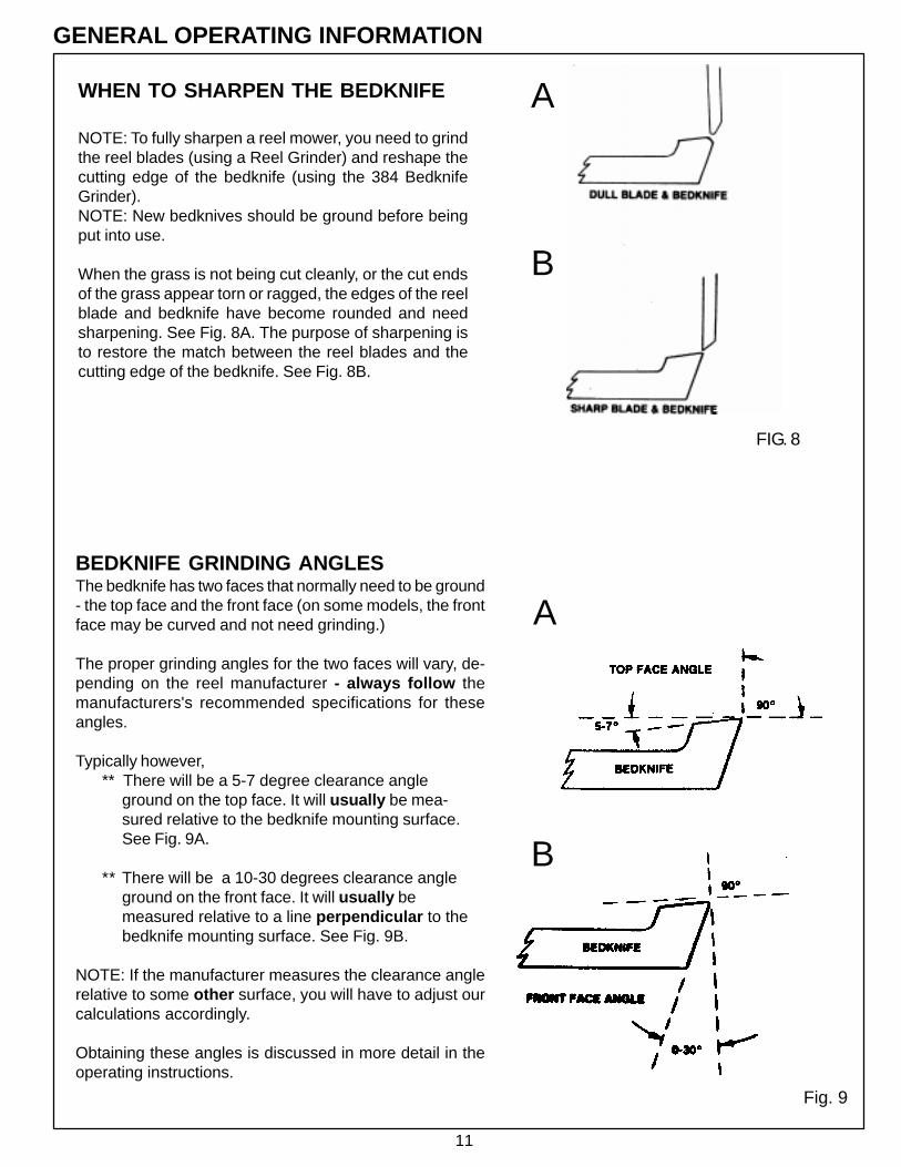
WHEN TO SHARPEN THE BEDKNIFE
NOTE: To fully sharpen a reel mower, you need to grindthe reel blades (using a Reel Grinder) and reshape thecutting edge of the bedknife (using the 384 BedknifeGrinder).NOTE: New bedknives should be ground before beingput into use.
When the grass is not being cut cleanly, or the cut endsof the grass appear torn or ragged, the edges of the reelblade and bedknife have become rounded and needsharpening. See Fig. 8A. The purpose of sharpening isto restore the match between the reel blades and thecutting edge of the bedknife. See Fig. 8B.
Fig. 9
BEDKNIFE GRINDING ANGLESThe bedknife has two faces that normally need to be ground- the top face and the front face (on some models, the frontface may be curved and not need grinding.)
The proper grinding angles for the two faces will vary, de-pending on the reel manufacturer - always follow themanufacturers's recommended specifications for theseangles.
Typically however,** There will be a 5-7 degree clearance angle
ground on the top face. It will usually be mea-sured relative to the bedknife mounting surface.See Fig. 9A.
** There will be a 10-30 degrees clearance angleground on the front face. It will usually bemeasured relative to a line perpendicular to thebedknife mounting surface. See Fig. 9B.
NOTE: If the manufacturer measures the clearance anglerelative to some other surface, you will have to adjust ourcalculations accordingly.
Obtaining these angles is discussed in more detail in theoperating instructions.
A
B
A
B
FIG. 8
12
GENERAL OPERATING INFORMATION (Continued)
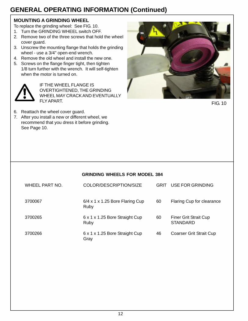
MOUNTING A GRINDING WHEELTo replace the grinding wheel: See FIG. 10.1. Turn the GRINDING WHEEL switch OFF.2. Remove two of the three screws that hold the wheel
cover guard.3. Unscrew the mounting flange that holds the grinding
wheel - use a 3/4" open-end wrench.4. Remove the old wheel and install the new one.5. Screws on the flange finger tight, then tighten
1/8 turn further with the wrench. It will self-tightenwhen the motor is turned on.
IF THE WHEEL FLANGE ISOVERTIGHTENED, THE GRINDINGWHEEL MAY CRACK AND EVENTUALLYFLY APART.
6. Reattach the wheel cover guard.7. After you install a new or different wheel, we
recommend that you dress it before grinding.See Page 10.
GRINDING WHEELS FOR MODEL 384
WHEEL PART NO. COLOR/DESCRIPTION/SIZE GRIT USE FOR GRINDING
3700067 6/4 x 1 x 1.25 Bore Flaring Cup 60 Flaring Cup for clearanceRuby
3700265 6 x 1 x 1.25 Bore Straight Cup 60 Finer Grit Strait CupRuby STANDARD
3700266 6 x 1 x 1.25 Bore Straight Cup 46 Coarser Grit Strait CupGray
FIG. 10

13
DRESSING THE GRINDING WHEELThere are two methods to dress the grinding wheel, thedressing brick which comes standard with the grinder and thediamond dresser which is optional for the grinder. Dress thegrinding wheel whenever there is any glazing ("glazing" is thebuildup of stone dust and grinding grit on the face of the wheel).For best results, also dress the wheel before making the finalgrind.
REFER ALSO TO THE "SAFETY RULES WHENGRINDING" ON PAGE 5.
For dressing, move the grinding head to the left hand side of themachine as shown in FIG. 11, so you are clear of the bedknife.Don't change the angle of the grinding head when dressing.With the wheel spinning, use the dressing brick to dress theface of the wheel, See FIG. 12, or with the diamond dresser,move the grinding head and grinding wheel over the dresserand turn the dresser adjusting screw until the diamond pointjust touches the wheel. It may be necessary to loosen thehorizontal slide and move the grinding head to the diamonddresser. See FIG. 13.
NOTE: Excessive dressing will shorten the life of the wheel.The grinding wheel can only be dressed with the diamonddresser in the top face grinding position.
Replacing the WheelA new grinding wheel is 1" [25 mm] deep. When it wears downto a depth of 0.62" [15 mm], it should be replaced. See FIG. 14.
GENERAL OPERATING INFORMATION (Continued)
CONTROLLING TEMPERATURE
There are two suggested methods for controlling thetemperature of the grinding wheel during the grindingprocess in order to avoid heat distortion and achieveoptimum results:
A. Begin by dry grinding the bedknife. Then allow thebedknife to cool completely before doing thefinal grind. NOTE: It may be necessary to wait anhour between grinds for the bedknife to coolcompletely).
B. The second method would be to use a spray bottlewith water or a wet rag or sponge to cool thebedknife between grinding passes.
FIG. 14
.62 [15mm] minimum
FIG. 11
FIG. 12
FIG. 13

14
GENERAL OPERATING INSTRUCTIONS (Continued)
USING A FLARE CUP WHEELFOR ADDED CLEARANCEThe shape of some bed bars requires using anoptional flare-cup grinding wheel to clear the endsupports. See FIG. 15.
Flare-cup wheels can be ordered in 6 [150 mm]diameter. For Part No. and description, refer to theGrinding Wheels list on Page 12.
ROTATING THE GRINDING WHEEL GUARDThe grinding wheel guard is held in position with alocking T-knob. Loosen the T-knob to rotate the guard.See FIG. 16
LINK MOUNTINGSome bedknives require extra support because of theweight of their center bracket or because of excessiveimbalance in the weight of the knife.
Link components for providing this support aresupplied with the Grinder in a separate bag. Attach thelinks to the bedknife bracket and to the bar on the middlesupport, then adjust their length as required.See FIG. 17.
FLARE CUP FIG. 15
FIG. 17
FIG. 16
THUMBSCREW

15
OPERATING INSTRUCTIONSINSTALL THE BEDKNIFE
1. Inspect the Bedknife : Inspect the bedknife and bar fordamage (cracks, warpage, bushing wear, excessive knifewear.) Replace or repair as required. (See Manufacturer'sManual.) Thoroughly clean the bedknife, especially on thebottom where the middle support's will contact.
Prepare the Machine for MountingPivot the grinding head to the vertical position. Move it allthe way to the left, then crank it up (so the adjustablecenter stand will be easier to reposition).Always wipe any grindings, dirt, etc. from the base beforemoving the center stands.
2. Mount the bedknife: Mount the bedknife assemblybetween the centers on the bedknife grinder. Adjust the bladesupport bar so the top face to be ground is held at an angle ofapproximately 30 degrees from horizontal plane.With the blade at this angle, there will be very little vertical orhorizontal adjustments required as the motor is pivoted togrind both surfaces. This position is arbitrary. The grindinghead clearance to motor base will determine final adjustments.NOTE: The 30 degree angle may be less for somebedknife faces that are close to the pivot mounting position,so there will be clearance between the grinding head and theadjustable center assembly.
The center stands must be lockedsecurely in place. Any looseness willadversely affect grind quality.
ALIGN THE CENTERSPlace the alignment gauge onto the base and adjust thealignment gauge so the projecting edge is touching thetop diameter and side of the fixed center as shown inFiG. 18 and FIG. 19.Without moving any of the adjustments made on thealignment gauge, place the alignment gauge over theadjustable center and adjust the adjustable centeraccordingly until it is just touching the alignment gaugetop and side. See FIG. 20.Your bedknife mounting holes are now in line withcarriage travel. For accuracy of setup always adjust thevertical and horizontal adjustment so you adjust up to thealignment gauge edge.The adjustable center lock must be securely tightenedand the fixed and adjustable center must be securelytightened to the base. Any looseness will adversely affectgrind quality.
DON'T FORCE THE CENTER TIGHTLY INTO THEBEDBAR. THIS COULD DISTORT AND MISALIGNTHE ADJUSTABLE SUPPORT. LEAVE THE CENTERLOOSE BY .005 - .015" [.15-.40mm], THEN REMOVETHIS LOOSENESS AS EXPLAINED BELOW.
With your hand turn the center on the adjustable centerstand until the bedbar is held snugly with zero free play.
FIG. 19
FIG. 20
SOME BEDKNIVES REQUIREEXTRA SUPPORT BECAUSE OFTHEIR IMBALANCE.REFER TO "LINK MOUNTING" ONPAGE 14.
FIG. 18

16
GRINDING THE TOP FACENOTE: The following instructions presume that youhave already studied "General OperatingInformation" starting on Page 11.
Loosen the thumbscrew on the wheel guard and rotateto the rear and lock in place.
If you want to match the exsisting angle , place theAngle Finder on the bedknife as shown in FIG. 21A.Read the angle indicated on the magnetic bubbleindicator to which the bedknife is mounted. Then placethe bubble indicator on top of the motorhead as shownin FIG. 22.Adjust the motor head until it is positioned at the sameangle as the bedknife face. You have now matched themotorhead angle to the top face of the bedknife.
NOTE: The bedknife may have been excessivelyadjusted and lapped since its last grind. In thesecases, establish the bedknife angle from the small topsurface outside the wear area as shown in FIG. 21A.If you want to set the angle to the manufacturer'sspecifications , measure the mounting surface angle atthe top or bottom of the bedknife as shown in FIG. 21Band then get the correct working angle from page 21 ofthis manual. Then add or subtract the relief angle todetermine the grinding wheel angle.
When you have the motor head angle set, adjust themotorhead protractor angle scale to 0 degrees. SeeFIG. 24.
Handcrank the vertical feed adjustment knobs andmove the horizontal adjustment until grinding wheel justtouches the face of the bedknife and covers the surfaceto be ground. At this point the grinding wheel rim is toextend over the bedknife top surface being ground by1/2" whenever possible. See FIG. 23.
OPERATING INSTRUCTIONS (Continued)
If the grinding wheel rim does notextend over the bedknife face, it willwear unevenly and cause groovesacross the surface of bedknife.
FIG. 21
FIG. 22
FIG. 23
When the grinding wheel cannot extend over thebedknife surface, dress the grinding wheel moreoften.
THE HEAD IS HEAVY AND MUSTBE SUPPORTED WHEN THELOCK IS RELEASED.
If you don't have the optional angle finder, you willhave to adjust the grinding head angle to matchthe bedknife angle by visually matching the wheelangle to the bedknife angle.
For final adjustments, turn the GRINDING WHEELswitch OFF and manually touch the wheel to thebedknife top face to where it is contacting. Lookat the scratch marks to determine that they go fullyacross the bedknife face. If not, adjust the angleof the motor head until they match.

17
OPERATING INSTRUCTIONS (Continued)TOP FACE GRINDING (continued)
Next, back off the grinding wheel only enough sothat it is no longer touching the bedknife face.Move the carriage down to the end of the bedknifethat is supported by the adjustable center standuntil the contact area of the grinding wheel isbeyond the end of the bedknife. See note below oncontact area. Check for clearance between thegrinding wheel, the bedbar and the adjustablecenter stand assembly. If there is interference,reposition the components or change to the flaredcup grinding wheel as described on Page 14.
Move the length of the bedknife and watch thegrinding head to ensure that the grinding wheel istraveling the complete length of the bedknife. Moveto the fixed center end of the knife and verifyclearance as the head comes of the knife asshown in FIG. 25.
When satisfied with the grinding head travel, crankthe vertical feed adjustment knob down until thegrinding wheel is removing metal lightly from thebedknife. Now travel the full length of the bedknifeto determine the high point. If the high point isexcessive to the low point, reverify the centersalignment before proceeding.
When you are satisfied with the grinding headtravel, begin grinding. Set the GRINDING WHEELswitch at ON.
NOTE: At this point you won't know the condition ofthe grinding wheel after the previous job. Alwaysdress the wheel before grinding. See Page 13.
It is recommended to take off approximately .002"per pass. Rotating the vertical feed handwheel 7degrees of a turn will remove approximately .002"per pass. Continue grinding the bedknife in thismanner until the grinding process is complete.
BEDKNIFE COOLING IS CRITICAL TO AQUALITY GRIND. DURING THE GRIND ANDSPARKOUT PROCESS, COOL THEBEDKNIFE FOLLOWING THE OPTIONSLISTED ON PAGE 13.
NOTE: The area of the grinding wheel whichcontacts the bedknife is on the left side of themotor. The area of the wheel which doesn'tcontact will still be over the bedknife. See FIG.25. (When you go to the right end of theGrinder, the wheel traverses completely off thebedknife.)
FIG. 25
When the grind is complete, dress the grind-ing wheel, cool the knife and spark out.
Infeed the grinding head for onlyapproximately .002" stock removal in finalpasses and let the grinding wheel spark out.For sparking out in grinding process, alwaystraverse grinding head 10 or more passeswith no grinding head infeed.
NOTE: This process refers to sparkout, butwhat we are looking for is a near spark out,approximately a 99% reduction in grindingspark from normal grind. Do not run sparkoutuntil you have no sparks, because this couldbe an extremely extended period. Watch thesparks grinding pattern for the full length ofgrind. The sparks should look equal for the fulllength.
FIG. 24

18
OPERATING INSTRUCTIONS (Continued)
GRINDING THE FRONT FACE
NOTE: On some mower bedknives, the front face iscurved and therefore may not have to be sharpened.
Reposition the Head for Front-Face GrindingSet the head angle protractor to zero (if not already atzero) after the top face is ground. Then pivot the grindinghead so it is in position to grind the front face. Move thegrinding head to the right end of the carriage (beyond theend of the bedknife). See FIG. 26. Loosen the grindinghead lock lever and rotate the head to the manufacturer'sangle specified on page 21 using the head angle protrac-tor. See FIG. 27.
THE HEAD IS HEAVY AND MUST BE SUP-PORTED WHEN THE LOCK LEVER ISRELEASED.
Reset the wheel guard as shown by loosening theT-knobs and swinging the guard around 180 degreesso the wheel can grind the front face of the bedknife.See FIG. 16.
If you want to match the exsisting angle , place theAngle Finder on the bedknife. Read the angle indi-cated on the magnetic bubble indicator to which thebedknife is mounted. Then place the bubble indicatoron end of the motorhead. Adjust the motor head untilit is positioned at the same angle as the bedknifeface. You have now matched the motorhead angle tothe top face of the bedknife.
THE HEAD IS HEAVY AND MUST BESUPPORTED WHEN THE LOCK LEVERIS RELEASED.
If you don't have the optional angle finder, you will haveto adjust the grinding head angle to match thebedknife angle by visually matching the wheel angle tothe bedknife angle.
For final adjustments, turn the GRINDING WHEELswitch OFF and manually touch the wheel to thebedknife top face to where it is contacting. Look atthe scratch marks to determine that they go fullyacross the bedknife face. If not, adjust the angle of themotor head until they match.
FIG. 27
FIG. 26

19
OPERATING INSTRUCTIONS (Continued)GRINDING THE FRONT FACE (Continued)Hand crank the vertical feed adjustment knobs and movethe horizontal adjustment until grinding wheel just touchesthe face of the bedknife and covers the surface to beground. At this point the grinding wheel rim is to extendover the bedknife surface being ground by 1/2" wheneverpossible. See FIG. 28.
Grind the Bedknife
REFER ALSO TO THE "SAFETY RULES WHENGRINDING" ON PAGE 5.
Next, back off the grinding wheel only enough so that it isno longer touching the bedknife face. Move the carriagedown to the end of the bedknife that is supported by theadjustable center stand until the contact area of thegrinding wheel is beyond the end of the bedknife. Seenote below on contact area. Check for clearancebetween the grinding wheel, the bedbar and theadjustable center stand assembly. If there is interference,reposition the components or change to the flared cupgrinding wheel as described on Page 14.
Move the length of the bedknife and watch the grindinghead to ensure that the grinding wheel is traveling thecomplete length of the bedknife. Move to the fixed centerend of the knife and verify clearance as the head comesof the knife as shown in FIG. 29.
When satisfied with the grinding head travel, crank thevertical feed adjustment knob down until the grindingwheel is removing metal lightly from the bedknife. Nowtravel the full length of the bedknife to determine the highpoint.
When you are satisfied with the grinding head travel,begin grinding. Set the GRINDING WHEEL switch at ON.
Crank the head until the wheel is removing metal lightly fromthe bedknife. We recommend taking off about .002 to .003"[.05 to .075 mm] per pass. When the head is horizontal,rotating the horizontal handwheel 7 degrees will removeabout .002 per pass.
Continue grinding the bedknife in this manner until you aresatisfied with the front face grind.
NOTE: The area of the grinding wheel whichcontacts the bedknife is on the left side of themotor. The area of the wheel which doesn'tcontact will still be over the bedknife. See FIG.29. (When you go to the right end of theGrinder, the wheel traverses completely off thebedknife.)
REMOVING THE BEDKNIFE
Screw back the adjustable centers.If the next bedknife is the same length, justmount it and screw out the adjustable center tosecure it. Don't move the adjustable (right)support unless the next bedknife is a differentlength.
BEDKNIFE COOLING IS CRITICAL TO AQUALITY GRIND. DURING THE GRIND ANDSPARKOUT PROCESS, COOL THEBEDKNIFE FOLLOWING THE OPTIONSLISTED ON PAGE 13.
FIG. 28
FIG. 29

20
MOUNTING BEDKNIVES WITHOUT CENTERING HOLES
Use Kit #3840553 shown in FIG. 30. When the kit isnot available, drill a 1/4" diameter hole in each end ofthe bedknife about 1/4" deep. It only has to be deepenough for the centers to go into. When using thisprocedure you cannot use the alignment gauge. Theblade has to be lined up by using a corner of thegrinding wheel. This is to be done by moving theadjustable center back and forth until the grindingwheel rubs the same on both ends of the blade.
Kit No. 3840553 for bed bars using slots for pivotwashers. The kit provides slugs with centers andclamps to allow mounting the bed bars in the grindercentering holes in the bed bars.
TORO MOUNTING KIT (OPTIONAL)
FIG. 30

21
Make
JacobsenJacobsenJacobsenJacobsenJacobsenJacobsenJacobsenJacobsenJacobsenJacobsenJacobsenJohn DeereLescoNationalRansomesRansomesRansomesToroToroToroToro
Model
19” & 22” Greens MowerBlitzer, F133, FairwayGreens King 418, 518, 422, 522Greens King 426, 526Greens King II, IV, IV Plus, VHFS, HM11LF1000, 123, 128, 3810Ranger, ST5111TF60Tri King 671, 1672, 1684, 1900Trim King, Turf King II, 76, 84All ModelsAll ModelsAll ModelsG-Plex 160Fairway, 250, 305, 405Motor 180, 350D, T-Plex 185GR500, 1000, 3000, HTM 175RM5100, 5300, 6500RM108, 216, 2300, 3500, 4500RM5, RM7, RMII, Spartan, Turf Pro
Front Angle inDegrees
0 to -50 to -50 to -50 to -50 to -50 to -50 to -50 to -50 to -50 to -50 to -5
-5-5-5
0 to -500
-15**-15**-15**-15**
Top Angle inDegrees
-8 to -10+4 to +6-8 to -10-8 to -10-8 to -10+4 to +6-8 to -10+4 to +6-8 to -10+4 to +6+4 to +6
-5-6-5
-8 to -10-3-3-5-5-5-5
Bed Knife Grind Angles