377Force!' Trolling Motor Installation...
8
FORCE ™ TROLLING MOTOR INSTALLATION INSTRUCTIONS Getting Started WARNING Do not run the motor when the propeller is out of the water. Contact with the rotating propeller may result in severe injury. Do not use the motor in areas where you or other people in the water may come into contact with the rotating propeller. Always disconnect the motor from the battery before cleaning or servicing the propeller to avoid injury. CAUTION When stowing or deploying the motor, be aware of the risk of entrapment or pinching from moving parts, which can result in injury. When stowing or deploying the motor, be aware of slick surfaces around the motor. Slipping when stowing or deploying the motor may result in injury. Always wear safety goggles, ear protection, and a dust mask when drilling, cutting, or sanding. NOTICE When drilling or cutting, always check what is on the opposite side of the surface. To avoid damage to your boat, this device should be installed by a qualified marine installer. Specific knowledge of marine electrical systems is required for proper installation. Tools and Supplies Needed • Drill and a 5 / 16 in. (8 mm) drill bit • #1 and #2 Phillips screwdrivers • 3 mm and 4 mm hex bits or wrenches (two 4 mm recommended) • 9 / 16 in. (14 mm) socket • Torque wrench • Circuit breaker rated for continuous 60 A • Trolling motor plug and receptacle rated for 60 A or greater (optional) • 6, 4, or 2 AWG (16, 25, or 35 mm 2 ) wire for extended runs of the power cable • Solder and heat-shrink tubing, if extending the power cable • Stainless steel pan head 1 / 4 -20 (M6x1) bolts (if the included bolts are not long enough to mount the motor to the deck) Installation Preparation Device Overview Shaft cap Power and transducer cables Steering system Mount Depth-adjustment collar Shaft Propeller drive motor Mounting Considerations When selecting a mounting location, observe these considerations. • You must install the motor on the bow of your boat. • It is recommended to install the motor on the port side of the bow, but you can install it on the starboard side if necessary. • You should install the mount so the deployed motor is as close to the center of the boat as possible. • You must install the mount with the bumper overhanging the gunwale of the boat. July 2019 190-02521-91_0C
Transcript of 377Force!' Trolling Motor Installation...

FORCE™ TROLLING MOTORINSTALLATION INSTRUCTIONS
Getting Started WARNING
Do not run the motor when the propeller is out of the water. Contact with the rotating propeller may result in severe injury.Do not use the motor in areas where you or other people in the water may come into contact with the rotating propeller.Always disconnect the motor from the battery before cleaning or servicing the propeller to avoid injury.
CAUTIONWhen stowing or deploying the motor, be aware of the risk of entrapment or pinching from moving parts, which can result in injury.When stowing or deploying the motor, be aware of slick surfaces around the motor. Slipping when stowing or deploying the motor may result in injury.Always wear safety goggles, ear protection, and a dust mask when drilling, cutting, or sanding.
NOTICEWhen drilling or cutting, always check what is on the opposite side of the surface.To avoid damage to your boat, this device should be installed by a qualified marine installer. Specific knowledge of marine electrical systems is required for proper installation.
Tools and Supplies Needed• Drill and a 5/16 in. (8 mm) drill bit• #1 and #2 Phillips screwdrivers• 3 mm and 4 mm hex bits or wrenches (two 4 mm
recommended)• 9/16 in. (14 mm) socket• Torque wrench• Circuit breaker rated for continuous 60 A• Trolling motor plug and receptacle rated for 60 A or greater
(optional)• 6, 4, or 2 AWG (16, 25, or 35 mm2) wire for extended runs of
the power cable• Solder and heat-shrink tubing, if extending the power cable• Stainless steel pan head 1/4-20 (M6x1) bolts (if the included
bolts are not long enough to mount the motor to the deck)
Installation PreparationDevice Overview
Shaft cap
Power and transducer cables
Steering system
Mount
Depth-adjustment collar
Shaft
Propeller drive motor
Mounting ConsiderationsWhen selecting a mounting location, observe these considerations.• You must install the motor on the bow of your boat.• It is recommended to install the motor on the port side of the
bow, but you can install it on the starboard side if necessary.• You should install the mount so the deployed motor is as
close to the center of the boat as possible.
• You must install the mount with the bumper overhanging the gunwale of the boat.
July 2019190-02521-91_0C
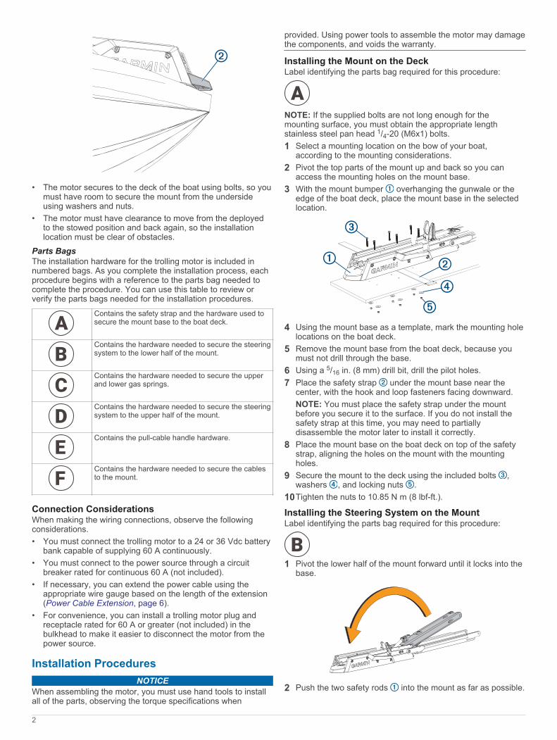
• The motor secures to the deck of the boat using bolts, so you must have room to secure the mount from the underside using washers and nuts.
• The motor must have clearance to move from the deployed to the stowed position and back again, so the installation location must be clear of obstacles.
Parts BagsThe installation hardware for the trolling motor is included in numbered bags. As you complete the installation process, each procedure begins with a reference to the parts bag needed to complete the procedure. You can use this table to review or verify the parts bags needed for the installation procedures.
Contains the safety strap and the hardware used to secure the mount base to the boat deck.
Contains the hardware needed to secure the steering system to the lower half of the mount.
Contains the hardware needed to secure the upper and lower gas springs.
Contains the hardware needed to secure the steering system to the upper half of the mount.
Contains the pull-cable handle hardware.
Contains the hardware needed to secure the cables to the mount.
Connection ConsiderationsWhen making the wiring connections, observe the following considerations.• You must connect the trolling motor to a 24 or 36 Vdc battery
bank capable of supplying 60 A continuously.• You must connect to the power source through a circuit
breaker rated for continuous 60 A (not included).• If necessary, you can extend the power cable using the
appropriate wire gauge based on the length of the extension (Power Cable Extension, page 6).
• For convenience, you can install a trolling motor plug and receptacle rated for 60 A or greater (not included) in the bulkhead to make it easier to disconnect the motor from the power source.
Installation ProceduresNOTICE
When assembling the motor, you must use hand tools to install all of the parts, observing the torque specifications when
provided. Using power tools to assemble the motor may damage the components, and voids the warranty.
Installing the Mount on the DeckLabel identifying the parts bag required for this procedure:
NOTE: If the supplied bolts are not long enough for the mounting surface, you must obtain the appropriate length stainless steel pan head 1/4-20 (M6x1) bolts.1 Select a mounting location on the bow of your boat,
according to the mounting considerations.2 Pivot the top parts of the mount up and back so you can
access the mounting holes on the mount base.3 With the mount bumper overhanging the gunwale or the
edge of the boat deck, place the mount base in the selected location.
4 Using the mount base as a template, mark the mounting hole locations on the boat deck.
5 Remove the mount base from the boat deck, because you must not drill through the base.
6 Using a 5/16 in. (8 mm) drill bit, drill the pilot holes.7 Place the safety strap under the mount base near the
center, with the hook and loop fasteners facing downward.NOTE: You must place the safety strap under the mount before you secure it to the surface. If you do not install the safety strap at this time, you may need to partially disassemble the motor later to install it correctly.
8 Place the mount base on the boat deck on top of the safety strap, aligning the holes on the mount with the mounting holes.
9 Secure the mount to the deck using the included bolts , washers , and locking nuts .
10Tighten the nuts to 10.85 N m (8 lbf-ft.).
Installing the Steering System on the MountLabel identifying the parts bag required for this procedure:
1 Pivot the lower half of the mount forward until it locks into the base.
2 Push the two safety rods into the mount as far as possible.
2
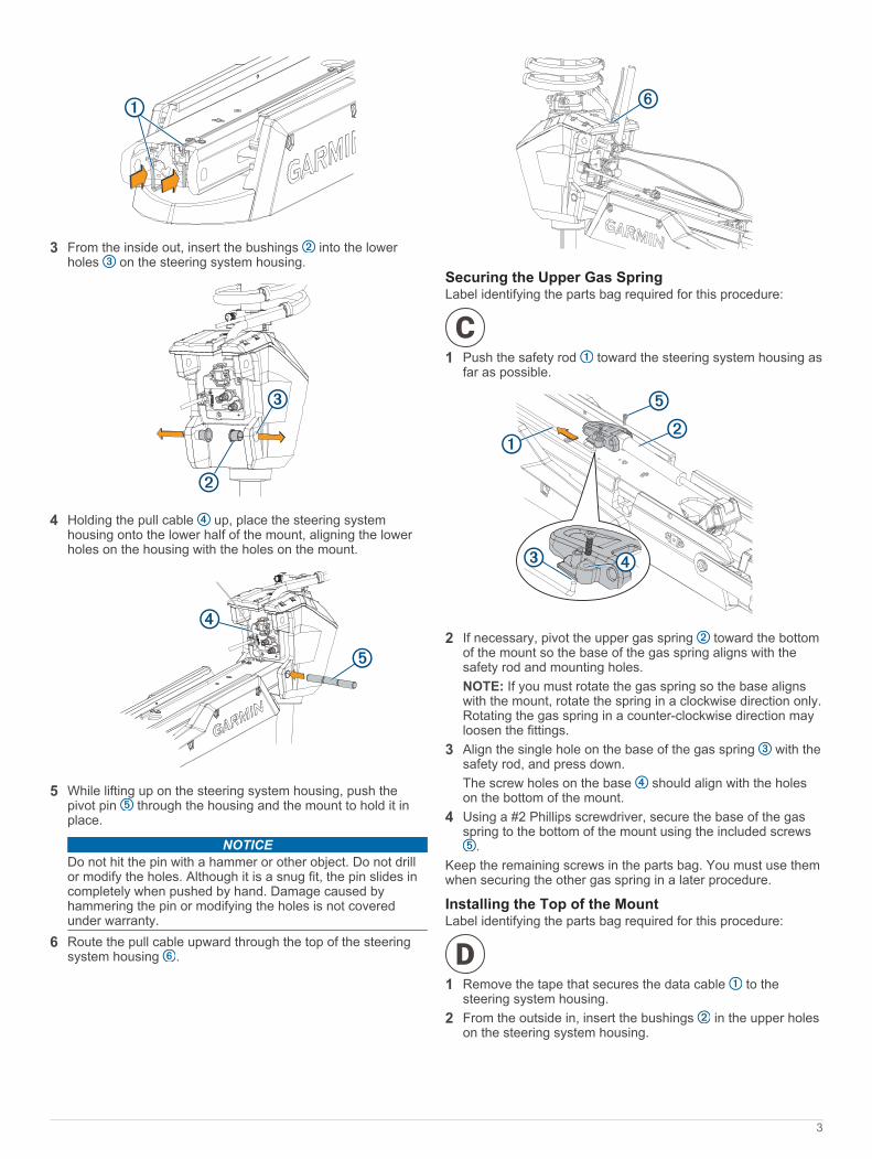
3 From the inside out, insert the bushings into the lower holes on the steering system housing.
4 Holding the pull cable up, place the steering system housing onto the lower half of the mount, aligning the lower holes on the housing with the holes on the mount.
5 While lifting up on the steering system housing, push the pivot pin through the housing and the mount to hold it in place.
NOTICEDo not hit the pin with a hammer or other object. Do not drill or modify the holes. Although it is a snug fit, the pin slides in completely when pushed by hand. Damage caused by hammering the pin or modifying the holes is not covered under warranty.
6 Route the pull cable upward through the top of the steering system housing .
Securing the Upper Gas SpringLabel identifying the parts bag required for this procedure:
1 Push the safety rod toward the steering system housing as far as possible.
2 If necessary, pivot the upper gas spring toward the bottom of the mount so the base of the gas spring aligns with the safety rod and mounting holes.NOTE: If you must rotate the gas spring so the base aligns with the mount, rotate the spring in a clockwise direction only. Rotating the gas spring in a counter-clockwise direction may loosen the fittings.
3 Align the single hole on the base of the gas spring with the safety rod, and press down.The screw holes on the base should align with the holes on the bottom of the mount.
4 Using a #2 Phillips screwdriver, secure the base of the gas spring to the bottom of the mount using the included screws
.Keep the remaining screws in the parts bag. You must use them when securing the other gas spring in a later procedure.
Installing the Top of the MountLabel identifying the parts bag required for this procedure:
1 Remove the tape that secures the data cable to the steering system housing.
2 From the outside in, insert the bushings in the upper holes on the steering system housing.
3

3 Pivot the top of the mount forward.
4 Tip the top of the steering system housing inward so the holes on the top of the mount and the housing align.
5 Push the pin through the holes on the top of the mount and the steering system housing.
6 Using a 4 mm hex bit or hex wrench, secure the pin using the screws and washers on both sides.
NOTE: To properly secure the pin, you should use two hex bits or wrenches so the pin does not rotate as you tighten the screws.
Connecting the Motor to the Display PanelNOTICE
You must connect the cable from the steering system to the display panel before proceeding further with the installation. If you do not make this connection now, the unsecured cable may damage the display panel when moving the mount.
1 Route the cable from the steering system housing to the display panel on the top of the mount.
2 Push the connector onto the port on the display panel, and rotate the locking ring clockwise to secure it.NOTE: The connector is keyed to fit into the port one way only, and will fit easily when aligned correctly. Do not force the connector into the port.
Installing the Handle on the Pull CableLabel identifying the parts bag required for this procedure:
1 Insert the pull cable through the bottom half of the handle .
2 Insert the pull cable through the washer .3 Push the R-pin through the hole on the end of the pull
cable.4 Pull the cable down so that the washer and R-pin rest in the
bottom half of the handle.NOTE: The R-pin fits in the bottom half of the handle one way only.
5 Using a #1 Philips screwdriver, secure the top of the handle to the bottom using the screws .
Routing the Power and Transducer Cables Through the MountLabel identifying the parts bag required for this procedure:
NOTICETo avoid damaging the power and transducer cables when deploying and stowing the trolling motor and to avoid interference with the GPS and heading sensors in the motor, you must route the cables through the right (starboard) side of the mount and secure them using the included hardware. You must not route the power cable through the left (port) side of the mount, and it is not possible to install the included brackets on the left (port) side. The left (port) side is reserved for additional accessories or transducer cables that you may install in the future.
4

1 Measure 40 cm (16 in.) on the power cable from where it connects to the steering system housing, and mark the cable with a marker or tape.
2 With the motor in the deployed position, route the transducer cable through the channel along the right (starboard) side of the mount .
TIP: To determine the right (starboard) side of the mount, stand in a location where you can read the information on the display panel.
3 Route the power cable through the channel above the transducer cable.
4 Using the pull cable, carefully lift the motor from the deployed position to the stowed position.
CAUTIONBecause only one of the lift-assist gas springs is secured at this point in the installation, you must use caution when lifting the motor to the stowed position. The weight of the motor may cause the mount to move quickly and pinch or crush hands or fingers.
5 Leaving a rounded bend in the cables , hold them against the side of the mount where they enter the channel.
6 At the location on the power cable you marked in step 1, place one of the brackets that has two screw holes over the cables and against the mount, aligning the holes on the bracket with the holes on the mount.
7 Using a 3 mm hex bit or wrench, secure the bracket to the mount using two screws .
8 Hold the cables against the bottom of the mount where they exit the channel.
9 Place the other bracket that has two screw holes over the cables and against the mount, aligning the holes on the bracket with the holes on the mount.
10Using a 3 mm hex bit or wrench, secure the bracket to the mount using two screws .
11Hold the cables against the plastic portion of the mount base, close to the boat deck.
12 Insert the lower tab on the remaining bracket into a slot below the cables , and rotate the bracket toward the mount base to hold the cables.
13Using a #1 Phillips screwdriver, secure the upper tab of the bracket to the mount base using a single screw .
14 Install additional plastic cable clips to secure the transducer cable to the power cable where needed (optional).Two plastic cable clips are included in the parts bag.
Securing the Lower Gas SpringLabel identifying the parts bag required for this procedure:
NOTE: This procedure uses the rest of the hardware in the parts bag that you used when installing the upper gas spring.1 Align the hole on the base of the lower gas spring with the
safety rod , and press down.
You may need to lift up the mount and flip over the gas spring if it was positioned on the other side of the mount during the previous installation steps.NOTE: If you must rotate the gas spring so the base aligns with the mount, rotate the spring in a clockwise direction only. Rotating the gas spring in a counter-clockwise direction may loosen the fittings.
2 Using a #2 Phillips screwdriver, secure the base of the lower gas spring to the mount using the included screws .
5

Installing the PropellerThe parts bag containing the hardware needed for this procedure is included in the box with the propeller and does not have a label.1 Insert the pin through the propeller motor shaft .
2 If necessary, rotate the motor shaft to orient the pin horizontally so it is less likely to fall out during installation.
3 Align the channel on the inside of the propeller with the pin, and slide the propeller onto the motor shaft.
4 Place the anode , washer , lock washer , and nut onto the end of the motor shaft.
5 Using a 9/16 in. (14 mm) socket, tighten the lock nut to 6 lbf-ft (8.13 N-m) to secure the propeller.
Connecting to Power1 Route the power cable to the breaker panel or the location
where you plan to install the breaker.2 If necessary, extend the power cable using the appropriate
wire gauge based on the length of the extension (Power Cable Extension, page 6) using solder and heat-shrink tubing.
3 Install a trolling motor plug and receptacle rated for 60 A or greater where the power cable enters a bulkhead (optional).
4 Connect the power cable to a circuit breaker rated for 60 A (continuous).
WARNINGThe circuit breaker must be in the off position before you connect the power cables from the trolling motor.
5 If necessary, connect the circuit breaker to a 60 A, 24 or 36 Vdc power source.
Power Cable ExtensionYou can extend the power cable using the appropriate gauge of wire based on the length of the extension.
NOTICEPower cable extensions must use single-conductor wire, with a minimum 75°C (167°F) insulation, that is not bundled, not sheathed, and not run through conduit. If you are using wire with 105°C (221°F) insulation or better, you can bundle up to three conductors inside a sheath or conduit outside of engine spaces.When installing the power cable extension, you must follow industry standards and best practices.
Extension length Minimum wire gauge Optimal wire gauge0 to 3 m (0 to 10 ft. ) 6 AWG (16 mm2) 6 AWG (16 mm2)3 to 4.6 m (10 to 20 ft.) 6 AWG (16 mm2) 4 AWG (25 mm2)4.6 to 9.1 m (20 to 30 ft.) 6 AWG (16 mm2) 2 AWG (35 mm2)
Connecting the Transducer to a ChartplotterThe built-in 12-pin transducer is compatible with select Garmin®
chartplotter models. Go to www.garmin.com or contact your Garmin dealer for more information.1 Route the transducer cable to the installed chartplotter.
2 Install the locking collar on the end of the transducer cable.3 Connect the transducer cable to the transducer port on the
back of the chartplotter.You can refer to the instructions provided with your chartplotter to identify the transducer port.
Stabilizer InstallationThe stabilizer is an optional accessory that can help stabilize and provide additional support for the trolling motor when it is in the stowed position.Installation instructions for the stabilizer are provided in the stabilizer box.
Foot Pedal InstallationThe foot pedal connects to the trolling motor wirelessly and is paired at the factory.Detailed mounting and power instructions are included in the Force Trolling Motor Foot Pedal Installation Instructions, in the foot pedal box. Operation instructions are included in the Force Trolling Motor Quick Start Manual.
Remote Control InstallationThe remote control connects to the trolling motor wirelessly and is paired at the factory.Operation instructions are included in the Force Trolling MotorQuick Start Manual.
Maintenance Needs and ScheduleTo maintain your warranty, you must perform a series of routine maintenance tasks as you prepare your motor for the season. If you use or transport the motor in dry, dusty environments (traveling on gravel roads, for example) you should perform these tasks more often during the season.For detailed procedures and information on service and replacement parts, download the Force Trolling Motor Maintenance Manual from www.garmin.com/manuals/force_trolling_motor.
• Examine the power cable for wear, and patch or repair as necessary .
• Check the power terminals, and clean them if necessary .• Lubricate the hinges and bushings .• Clean and lubricate the stow and deploy latch mechanism .• Check the mount rails, and replace them if necessary .• Check the mount bumper, and replace it if necessary .• Clean or replace the anodes in the propeller drive motor .
Motor InformationStowed Dimensions
6

Item 50 in. Model 57 in. Model1.558 m (615/16 in.) min.1.811 m (715/16 in.) max.
1.712 m (673/8 in.) min.2.066 m (815/16 in.) max.
300 mm (1113/16 in.) 340 mm (133/8 in.)
Deployed Dimensions
Item 50 in. Model 57 in. Model461 mm (18 1/8 in.) min.721 mm (28 3/8 in.) max.
488 mm (19 3/16 in.) min.817 mm (32 1/8 in.) max.
708 mm (27 7/8 in.) 799 mm (31 7/16 in.)
839 mm (33 1/16 in.) min.1.1 m (43 5/16 in.) max.
1.724 m (67 7/8 in.) max.920 mm (36 3/16 in.) min.
Item 50 in. Model 57 in. Model931 mm (36 11/16 in.) 1.022 m (40 1/4 in.)
402 mm (15 13/16 in.) 402 mm (15 13/16 in.)
203 mm (8 in.) 203 mm (8 in.)
Registering Your DeviceHelp us better support you by completing our online registration today. Keep the original sales receipt, or a photocopy, in a safe place.1 Go to my.garmin.com/registration.2 Sign in to your Garmin account.
Contacting Garmin Support• Go to support.garmin.com for help and information, such as
product manuals, frequently asked questions, videos, and customer support.
• In the USA, call 913-397-8200 or 1-800-800-1020.• In the UK, call 0808 238 0000.• In Europe, call +44 (0) 870 850 1241.
SpecificationsTrolling MotorWeight (motor, mount, and cables)
50 in. model: 30 kg (66 lb.)57 in. model: 31.75 kg (70 lb.)
Weight (stabilizer) 0.54 kg (1.2 lb.)Operating temperature
From -5° to 40°C (from 32° to 104°F)
Storage temperature From -40° to 85°C (-40° to 185°F)Material Mount and motor housing: aluminum
Shaft cap, display panel, and side panels: plasticMotor shaft: fiberglass
Water rating Shaft cap: IEC 60529 IPX51
Steering motor housing: IEC 60529 IPX72
Display panel housing: IEC 60529 IPX7Propeller drive motor housing: IEC 60529 IPX83
Compass safe distance
91 cm (3 ft.)
Power cable length 50 in. model: 1.2 m (4 ft.)57 in. model: 1.1 m (3.5 ft.)
Input voltage From 20 to 45 VdcInput amperage 60 A continuousBreaker (not included)
42 VDC or greater, suitable for 60 A continuousNOTE: You can protect the system buy using a larger circuit breaker, not to exceed 90 A, if you are operating under high temperatures or if you are sharing the circuit with other devices. You should verify that your boat wiring meets marine wiring standards using a larger breaker before changing it.
Main power usage at 36 Vdc 60 A
Off: 72 mWFull power: 2160 W
Radio frequency 2.4 GHz @ 28 dBm nominal
Remote ControlDimensions (W×H×D) 152 x 52 x 32 mm (6 x 2 x 11/4 in.)Weight 109 g (3.8 oz.) without batteriesMaterial Glass-filled nylonDisplay type Sunlight-visible, transflective memory-in-pixel
(MIP)Display resolution R240 x 240 pixelsDisplay size (diameter) 30.2 mm (13/16 in.)Operating temperature From -15° to 55°C (5° to 131°F)Storage temperature From -40° to 85°C (-40° to 185°F)Battery type 2 AA (not included)Battery life 240 hr., typical useRadio frequency 2.4 GHz @ 3.4 dBm nominalWater rating IEC 60529 IPX74
Compass-safe distance 15 cm (6 in.)
© 2019 Garmin Ltd. or its subsidiariesGarmin®, the Garmin logo, and ActiveCaptain™ are trademarks of Garmin Ltd. or its subsidiaries, registered in the USA and other countries. Force™ is a trademark of Garmin Ltd. or its subsidiaries. These trademarks may not be used without the express permission of Garmin.You should reference United States Code of Federal Regulations: 33 CFR 183 - Boats and Associated Equipment and ABYC E-11: AC and DC Electrical Systems on Boats when installing this trolling motor.
1 The part withstands projected water exposure from any direction (such as rain).2 The part withstands incidental immersion in water up to 1 m deep for up to 30 min.3 The part withstands continuous immersion in water up to 3 m deep.4 *The device withstands incidental exposure of water up to 1 m for up to 30 min.
7

© 2019 Garmin Ltd. or its subsidiaries support.garmin.com