372 IEEE TRANSACTIONS ON MICROWAVE THEORY AND …
13
372 IEEE TRANSACTIONS ON MICROWAVE THEORY AND TECHNIQUES, VOL. 56, NO. 2, FEBRUARY 2008 Multi-Lookup Table FPGA Implementation of an Adaptive Digital Predistorter for Linearizing RF Power Amplifiers With Memory Effects Pere L. Gilabert, Albert Cesari, Student Member, IEEE, Gabriel Montoro, Eduard Bertran, Senior Member, IEEE, and Jean-Marie Dilhac, Senior Member, IEEE Abstract—This paper presents a hardware implementation of a digital predistorter (DPD) for linearizing RF power amplifiers (PAs) for wideband applications. The proposed predistortion lin- earizer is based on a nonlinear auto-regressive moving average (NARMA) structure, which can be derived from the NARMA PA behavioral model and then mapped into a set of scalable lookup tables (LUTs). The linearizer takes advantage of its recursive na- ture to relax the LUT count needed to compensate memory effects in PAs. Experimental support is provided by the implementation of the proposed NARMA DPD in a field-programmable gate-array device to linearize a 170-W peak power PA, validating the recursive DPD NARMA structure for W-CDMA signals and flexible trans- mission bandwidth scenarios. To the best of the authors’ knowl- edge, it is the first time that a recursive structure is experimentally validated for DPD purposes. In addition to the results on PA ef- ficiency and linearity, this paper addresses many practical imple- mentation issues related to the use of FPGA in DPD applications, giving an original insight on actual prototyping scenarios. Finally, this study discusses the possibility of further enhancing the overall efficiency by degrading the PA operation mode, provided that DPD may be unavoidable due to the impact of memory effects. Index Terms—Digital predistortion (DPD), field programmable gate array (FPGA), nonlinear auto-regressive moving average (NARMA) models, power amplifier (PA) linearization. I. INTRODUCTION C URRENT studies regarding the needs of wireless commu- nications equipment agree in highlighting the importance of reducing power consumption to cut running costs as an added value. Besides, linearity requirements are specified in commu- nication standards and, thus, reducing unacceptable distortions is mandatory [1], [2]. Nevertheless, new standards enhancing high data rates by means of spectrally efficient complex modu- Manuscript received June 25, 2007; revised October 23, 2007. This work was supported in part by the Spanish Government (MEC) under Project TEC2005- 07985-C03-02 and by the European Union Network Top Amplifier Research Group in a European Team (TARGET) under Grant IST-1-507893-NOE. P. L. Gilabert, G. Montoro, and E. Bertran are with the Department of Signal Theory and Communications, Technical University of Catalonia (UPC), 08860 Castelldefels, Barcelona, Spain (e-mail: [email protected]; montoro@tsc. upc.edu; [email protected]). A. Cesari and J.-M. Dilhac are with the Laboratoire d’Architecture et d’Analyse des Systèmes (LAAS)–Centre National de la Recherche Scientifique (CNRS), Université de Toulouse, 31077 Toulouse Cedex 4, France (e-mail: [email protected]; [email protected]). Color versions of one or more of the figures in this paper are available online at http://ieeexplore.ieee.org. Digital Object Identifier 10.1109/TMTT.2007.913369 lation schemes require power amplifiers (PAs) handling signals that present high peak-to-average power ratios (PAPRs). Those spectrally efficient modulation formats are unfortu- nately very sensitive to the intermodulation distortion (IMD) that results from nonlinearities in the RF transmitter chain, mainly due to the PA nonlinear behavior. This implies that for having linear amplification, significant backoff (BO) levels of operation are required, thus penalizing power efficiency in the PA. For example, in the cellular telephony context, PAs have to support some of the code division multiple ac- cess (CDMA) family [CDMA2000, evolution data optimized (EVDO), W-CDMA, long-term evolution (LTE)] of wireless standards exhibiting typical PAPR figures around 10 dB. In a broadband access context, communications standards such as IEEE 802.11a, DVB-T, or the IEEE 802.16 consider the use of orthogonal frequency division multiplexing (OFDM) signals presenting even higher PAPRs (up to 14 dB) and bandwidths up to 20 MHz or wider. Furthermore, in base stations, the PA has to handle a composite RF signal resulting from the sum of several independent modulated carriers. The wider bandwidths and increased PAPR figures aggravate the linearity versus efficiency problem. A recognized solution to avoid the power inefficient BO operation is the use of PA linearizers. Among linearizers, digital predistortion (DPD) is on its way of becoming one of the most important linearization techniques due to the availability of faster digital signal processing (DSP) hardware, replacing feedforward as the mainstream technique in commercially available base-station products. Manufacturers of chipsets (PMC-Sierra, Xilinx Inc., Altera), PA rack systems (Andrew, Powerwave), and base stations (Lucent-Alcatel, Ericsson) propose different types of DPD solutions. Besides the efficiency problem, coping with high-speed envelope signals makes designers reconsider the degradation suffered from PA memory effects since their impact is more relevant as the signal bandwidth increases. Actually, due to PA dynamics, the amplified signal not only depends on the input signal at the same time instant, but also on the history of the input–output signals as well. Therefore, PA memory effects have to also be taken into account when designing linearizers. DPD has been the subject of multiple publications in that memory compensation area [3]–[10], demonstrating the effec- tiveness of a variety of approaches to counteract both memory effects and nonlinear behavior of the RF PA. However, little at- tention has been drawn to practical implementations of such sys- tems [11]–[17]. This study aims to contribute to that field by 0018-9480/$25.00 © 2008 IEEE
Transcript of 372 IEEE TRANSACTIONS ON MICROWAVE THEORY AND …

372 IEEE TRANSACTIONS ON MICROWAVE THEORY AND TECHNIQUES, VOL. 56, NO. 2, FEBRUARY 2008
Multi-Lookup Table FPGA Implementation of anAdaptive Digital Predistorter for Linearizing RF
Power Amplifiers With Memory EffectsPere L. Gilabert, Albert Cesari, Student Member, IEEE, Gabriel Montoro, Eduard Bertran, Senior Member, IEEE,
and Jean-Marie Dilhac, Senior Member, IEEE
Abstract—This paper presents a hardware implementation ofa digital predistorter (DPD) for linearizing RF power amplifiers(PAs) for wideband applications. The proposed predistortion lin-earizer is based on a nonlinear auto-regressive moving average(NARMA) structure, which can be derived from the NARMA PAbehavioral model and then mapped into a set of scalable lookuptables (LUTs). The linearizer takes advantage of its recursive na-ture to relax the LUT count needed to compensate memory effectsin PAs. Experimental support is provided by the implementationof the proposed NARMA DPD in a field-programmable gate-arraydevice to linearize a 170-W peak power PA, validating the recursiveDPD NARMA structure for W-CDMA signals and flexible trans-mission bandwidth scenarios. To the best of the authors’ knowl-edge, it is the first time that a recursive structure is experimentallyvalidated for DPD purposes. In addition to the results on PA ef-ficiency and linearity, this paper addresses many practical imple-mentation issues related to the use of FPGA in DPD applications,giving an original insight on actual prototyping scenarios. Finally,this study discusses the possibility of further enhancing the overallefficiency by degrading the PA operation mode, provided that DPDmay be unavoidable due to the impact of memory effects.
Index Terms—Digital predistortion (DPD), field programmablegate array (FPGA), nonlinear auto-regressive moving average(NARMA) models, power amplifier (PA) linearization.
I. INTRODUCTION
CURRENT studies regarding the needs of wireless commu-nications equipment agree in highlighting the importance
of reducing power consumption to cut running costs as an addedvalue. Besides, linearity requirements are specified in commu-nication standards and, thus, reducing unacceptable distortionsis mandatory [1], [2]. Nevertheless, new standards enhancinghigh data rates by means of spectrally efficient complex modu-
Manuscript received June 25, 2007; revised October 23, 2007. This work wassupported in part by the Spanish Government (MEC) under Project TEC2005-07985-C03-02 and by the European Union Network Top Amplifier ResearchGroup in a European Team (TARGET) under Grant IST-1-507893-NOE.
P. L. Gilabert, G. Montoro, and E. Bertran are with the Department of SignalTheory and Communications, Technical University of Catalonia (UPC), 08860Castelldefels, Barcelona, Spain (e-mail: [email protected]; [email protected]; [email protected]).
A. Cesari and J.-M. Dilhac are with the Laboratoire d’Architecture etd’Analyse des Systèmes (LAAS)–Centre National de la Recherche Scientifique(CNRS), Université de Toulouse, 31077 Toulouse Cedex 4, France (e-mail:[email protected]; [email protected]).
Color versions of one or more of the figures in this paper are available onlineat http://ieeexplore.ieee.org.
Digital Object Identifier 10.1109/TMTT.2007.913369
lation schemes require power amplifiers (PAs) handling signalsthat present high peak-to-average power ratios (PAPRs).
Those spectrally efficient modulation formats are unfortu-nately very sensitive to the intermodulation distortion (IMD)that results from nonlinearities in the RF transmitter chain,mainly due to the PA nonlinear behavior. This implies thatfor having linear amplification, significant backoff (BO) levelsof operation are required, thus penalizing power efficiencyin the PA. For example, in the cellular telephony context,PAs have to support some of the code division multiple ac-cess (CDMA) family [CDMA2000, evolution data optimized(EVDO), W-CDMA, long-term evolution (LTE)] of wirelessstandards exhibiting typical PAPR figures around 10 dB. In abroadband access context, communications standards such asIEEE 802.11a, DVB-T, or the IEEE 802.16 consider the use oforthogonal frequency division multiplexing (OFDM) signalspresenting even higher PAPRs (up to 14 dB) and bandwidthsup to 20 MHz or wider. Furthermore, in base stations, the PAhas to handle a composite RF signal resulting from the sum ofseveral independent modulated carriers. The wider bandwidthsand increased PAPR figures aggravate the linearity versusefficiency problem. A recognized solution to avoid the powerinefficient BO operation is the use of PA linearizers.
Among linearizers, digital predistortion (DPD) is on its wayof becoming one of the most important linearization techniquesdue to the availability of faster digital signal processing (DSP)hardware, replacing feedforward as the mainstream techniquein commercially available base-station products. Manufacturersof chipsets (PMC-Sierra, Xilinx Inc., Altera), PA rack systems(Andrew, Powerwave), and base stations (Lucent-Alcatel,Ericsson) propose different types of DPD solutions.
Besides the efficiency problem, coping with high-speedenvelope signals makes designers reconsider the degradationsuffered from PA memory effects since their impact is morerelevant as the signal bandwidth increases. Actually, due to PAdynamics, the amplified signal not only depends on the inputsignal at the same time instant, but also on the history of theinput–output signals as well. Therefore, PA memory effectshave to also be taken into account when designing linearizers.
DPD has been the subject of multiple publications in thatmemory compensation area [3]–[10], demonstrating the effec-tiveness of a variety of approaches to counteract both memoryeffects and nonlinear behavior of the RF PA. However, little at-tention has been drawn to practical implementations of such sys-tems [11]–[17]. This study aims to contribute to that field by
0018-9480/$25.00 © 2008 IEEE

GILABERT et al.: MULTI-LUT FPGA IMPLEMENTATION OF ADAPTIVE DPD 373
focusing on topics uncovered in previously published demon-strators based on laboratory setups with vector signal genera-tors/analyzers in its core and delayed offline data processing.There, some questions regarding DPD application prototypinghave remained unexposed, such as follows:
• implementation: suitable real-time architectures, practicalimplementations, and DPD complexity dependence versusthe memory effects time span;
• efficiency: power consumption of the DPD itself and itsimpact on the transmitter efficiency;
• DPD adaptation: memory effects dependence on the spe-cific signal, and DPD ability to maintain linearity perfor-mances through signal changes in multicarrier and variablebandwidth systems.
This paper addresses those issues through experimentationwith a field-programmable gate-array (FPGA)-based DPD. Forthe first time, to the best of authors’ knowledge, a DPD basedon a nonlinear auto-regressive moving average (NARMA) ar-chitecture [18] is experimentally validated. The two distinctivecharacteristics of this NARMA-based DPD are its straightfor-ward deduction from the NARMA PA model, and its nonlinearrecursive structure aimed at relaxing the number of coefficientsrequired to reproduce PA dynamics. Moreover, this study inves-tigates the possibility to enhance the overall efficiency by de-grading the PA operation mode, assuming that the DPD is un-avoidable due to the unwanted impact of memory effects. Ex-perimental results on PA and DPD power consumption and lin-earity enhancement will be presented.
Therefore, this paper is organized as follows. Section II in-troduces DPD linearization issues related to PA memory effectsand its most remarkable influences. In Section III, we proposea multiple lookup table (LUT) architecture that is based in theNARMA DPD described in [18]. This multi-LUT architecturecan be mapped in an FPGA device. Practical issues regardingthis LUT-based architecture, such as LUT value filling, access,and addressing, are discussed in this section. Section IV de-scribes the experimental setup and procedures deployed to val-idate the proposed NARMA DPD. An insight on the PA modelestimation by means of the least squares (LS) algorithm to adaptthe DPD function is provided as well. In Section V, experi-mental results of the proposed NARMA DPD are provided. Fur-thermore, this section also discusses underlying practical topicssuch as the DPD power consumption, adaptation stability, andreliability. Section VI extends the contents of the preceding sec-tion by focusing on the impact on system performances of de-grading the PA operating point, focusing on the overall effi-ciency. The implications of using a DPD to further counteractthis more efficient, but less linear, degraded PA behavior are,therefore, investigated. Finally, in Section VII, conclusions aregiven.
II. PROBLEM STATEMENT
The DPD sensitivity to memory effects becomes a problemwhen trying to cancel distortion in wideband signals becauseit reduces linearization performance [19]. The most commonsources of memory effects recognized in the literature are dueto electrical and thermal dispersion effects. In addition, other
authors also take into account trapping effects and impact ion-ization as potential sources [20].
Traditionally, memory effects have been observed in the fre-quency domain as an asymmetry between the IMD productsusing a low PAPR two-tone test. However, in a realistic scenariothat considers signals presenting a high PAPR, the impact ofIMD products and hard nonlinearities decreases. Since the peakprobability is low, the PA operates in its linear region most ofthe time. As a consequence, its dynamics mainly manifest them-selves as unwanted in-band distortion. In such a case, memoryeffects can be better observed in the time domain (e.g., in-phaseand quadrature (I/Q) wave signals, constellation trajectories, de-cision points at demodulation) than in the frequency domain. Asit turns out, in-band distortion cannot be equalized by memory-less DPD unless some kind of filtering is considered togetherwith the nonlinear compensation.
In order to cancel or minimize memory effects, the envelopefiltering technique [19] is considered in this paper over othertechniques such as impedance optimization [21] and envelopeinjection [22]. The principle of the envelope filtering techniqueconsists of reproducing (in the predistorter) the inverse of thememory effects that are generated inside the PA, by means offiltering and phase shifting the envelope signal at baseband. Be-sides, the predistorter has to compensate the PA nonlinear be-havior as well. This technique can be readily transposed into aDPD system in order to deal with current challenges regardingPA nonlinearities and memory effects compensation within thetransmitter chain.
To do so, it is first necessary to identify a behavioral modelcapable of reproducing PA nonlinear dynamics. Later, from thisbehavioral model, it is possible to derive a suitable predistorterthat takes into account the envelope filtering technique. Thismodel has to satisfy three main constraints to be considered forDPD purposes. First, it has to be accurate in terms of memoryeffects reproduction. Second, it has to render a DPD implemen-tation without an excessive computational cost. Finally, it has tobe easy to extract and be invertible to facilitate the deduction ofthe predistortion function.
As a general introduction to the linearization architecture pre-sented in this paper, Fig. 1 shows a general block diagram of adigital baseband predistorter system. DPD is performed in anFPGA. The offline adaptation process consists of periodicallyupdating the suitable predistortion function from which the LUTcontents are deduced. The adaptation is carried out by a PC. Al-ternatively, it is possible to use a DSP board. As long as the PAcharacteristic drifts are slow, the LUT update frequency is re-laxed, and so is the hardware and computing constraints relatedto the adaptation procedures.
III. NARMA-BASED PREDICTIVE PREDISTORTER
A. Description of the DPD Function
By considering memory effects as secondary effects (despitetheir importance regarding linear distortion) with respect to amemoryless nonlinear behavior, it is possible to consider thatthe individual signal pulses propagate nonlinearly in time, buttend to sum up linearly [23]. For that reason, we have considered

374 IEEE TRANSACTIONS ON MICROWAVE THEORY AND TECHNIQUES, VOL. 56, NO. 2, FEBRUARY 2008
Fig. 1. Simplified block diagram of a digital baseband predistortion configuration within a transmitter.
Fig. 2. BPC for FPGA implementation [11]. The LUT is filled through a DATAand ADDRESS (ADDR) bus controlled by the chip select (CS) and write enable(WE) signals.
a NARMA model [24] to reproduce and later counteract short-term PA memory effects.
The advantage of using a NARMA model is the introductionof a nonlinear feedback path (infinite impulse response (IIR)terms) that may permit relaxing the number of delayed samplesconsidered to model the PA, in comparison to a model usingonly finite impulse response (FIR) terms. However, one of themain weaknesses of the NARMA model is its stability sincethe use of nonlinear feedback paths can result in overall systeminstability. Therefore, in order to guarantee the stability of aNARMA model, a stability test based in small gain theory ispresented in [24]. To determine the stability of nonlinear sys-tems, it is necessary to ensure that recursive nonlinear functionsare bounded by some kind of norm. Further details on the smallgain theory for nonlinear systems can be found in [25].
The predictive DPD based in a NARMA structure is de-scribed in [18], where DPD is carried out at baseband byadaptively forcing the PA to behave as a linear device. Thepredistortion function can be stated in terms of basic predis-tortion cells (BPCs). A BPC requires simple hardware blocks:a complex multiplier, a dual-port RAM memory block actingas the LUT, an address calculator, and two control ports: writeenable (WE) and chip select (CS), as is shown in Fig. 2.
Therefore, the BPCs are the fundamental building blocks ofthe DPD, as is shown in Fig. 3. The predistortion function statedin terms of combinations of BPCs can be expressed as
(1)
where is defined as
(2)
where (for both and ) are complex gains stored intheir corresponding LUT, is the output of the DPD, and
is the desired output defined as the signal to be trans-mitted multiplied by a linear amplification
(3)
In addition, and are the most significant sparse de-lays of the DPD input and output, respectively, that contributeat the description of the PA memory effects. The identifica-tion of these optimal delays and the definition of the minimumnecessary memory length to model PA memory effects are dis-cussed in [26]. More recently, heuristic search algorithms suchas the simulated annealing or genetic algorithms have also beenconsidered for these purposes. The use of the simulated an-nealing heuristic search algorithm has shown significant advan-tages (memory length reduction and better reliability) in com-parison to the use of simple consecutive delays to model PAdynamics [27].
B. LUT Spacing
How to organize the LUT spacing has been an interestingtopic of discussion for several years [28]–[30] since a uniformor nonuniform spacing of the LUT is closely related to the
GILABERT et al.: MULTI-LUT FPGA IMPLEMENTATION OF ADAPTIVE DPD 375
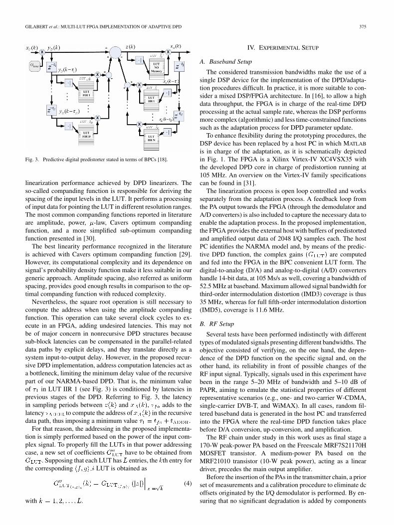
Fig. 3. Predictive digital predistorter stated in terms of BPCs [18].
linearization performance achieved by DPD linearizers. Theso-called companding function is responsible for deriving thespacing of the input levels in the LUT. It performs a processingof input data for pointing the LUT in different resolution ranges.The most common companding functions reported in literatureare amplitude, power, -law, Cavers optimum compandingfunction, and a more simplified sub-optimum compandingfunction presented in [30].
The best linearity performance recognized in the literatureis achieved with Cavers optimum companding function [29].However, its computational complexity and its dependence onsignal’s probability density function make it less suitable in ourgeneric approach. Amplitude spacing, also referred as uniformspacing, provides good enough results in comparison to the op-timal companding function with reduced complexity.
Nevertheless, the square root operation is still necessary tocompute the address when using the amplitude compandingfunction. This operation can take several clock cycles to ex-ecute in an FPGA, adding undesired latencies. This may notbe of major concern in nonrecursive DPD structures becausesub-block latencies can be compensated in the parallel-relateddata paths by explicit delays, and they translate directly as asystem input-to-output delay. However, in the proposed recur-sive DPD implementation, address computation latencies act asa bottleneck, limiting the minimum delay value of the recursivepart of our NARMA-based DPD. That is, the minimum valueof in LUT IIR 1 (see Fig. 3) is conditioned by latencies inprevious stages of the DPD. Referring to Fig. 3, the latencyin sampling periods between and , adds to thelatency to compute the address of in the recursivedata path, thus imposing a minimum value .
For that reason, the addressing in the proposed implementa-tion is simply performed based on the power of the input com-plex signal. To properly fill the LUTs in that power addressingcase, a new set of coefficients have to be obtained from
. Supposing that each LUT has entries, the th entry forthe corresponding LUT is obtained as
(4)
with .
IV. EXPERIMENTAL SETUP
A. Baseband Setup
The considered transmission bandwidths make the use of asingle DSP device for the implementation of the DPD/adapta-tion procedures difficult. In practice, it is more suitable to con-sider a mixed DSP/FPGA architecture. In [16], to allow a highdata throughput, the FPGA is in charge of the real-time DPDprocessing at the actual sample rate, whereas the DSP performsmore complex (algorithmic) and less time-constrained functionssuch as the adaptation process for DPD parameter update.
To enhance flexibility during the prototyping procedures, theDSP device has been replaced by a host PC in which MATLAB
is in charge of the adaptation, as it is schematically depictedin Fig. 1. The FPGA is a Xilinx Virtex-IV XC4VSX35 withthe developed DPD core in charge of predistortion running at105 MHz. An overview on the Virtex-IV family specificationscan be found in [31].
The linearization process is open loop controlled and worksseparately from the adaptation process. A feedback loop fromthe PA output towards the FPGA (through the demodulator andA/D converters) is also included to capture the necessary data toenable the adaptation process. In the proposed implementation,the FPGA provides the external host with buffers of predistortedand amplified output data of 2048 I/Q samples each. The hostPC identifies the NARMA model and, by means of the predic-tive DPD function, the complex gains are computedand fed into the FPGA in the BPC convenient LUT form. Thedigital-to-analog (D/A) and analog-to-digital (A/D) convertershandle 14-bit data, at 105 Ms/s as well, covering a bandwidth of52.5 MHz at baseband. Maximum allowed signal bandwidth forthird-order intermodulation distortion (IMD3) coverage is thus35 MHz, whereas for full fifth-order intermodulation distortion(IMD5), coverage is 11.6 MHz.
B. RF Setup
Several tests have been performed indistinctly with differenttypes of modulated signals presenting different bandwidths. Theobjective consisted of verifying, on the one hand, the depen-dence of the DPD function on the specific signal and, on theother hand, its reliability in front of possible changes of theRF input signal. Typically, signals used in this experiment havebeen in the range 5–20 MHz of bandwidth and 5–10 dB ofPAPR, aiming to emulate the statistical properties of differentrepresentative scenarios (e.g., one- and two-carrier W-CDMA,single-carrier DVB-T, and WiMAX). In all cases, random fil-tered baseband data is generated in the host PC and transferredinto the FPGA where the real-time DPD function takes placebefore D/A conversion, up-conversion, and amplification.
The RF chain under study in this work uses as final stage a170-W peak-power PA based on the Freescale MRF7S21170HMOSFET transistor. A medium-power PA based on theMRF21010 transistor (10-W peak power), acting as a lineardriver, precedes the main output amplifier.
Before the insertion of the PAs in the transmitter chain, a priorset of measurements and a calibration procedure to eliminate dcoffsets originated by the I/Q demodulator is performed. By en-suring that no significant degradation is added by components

376 IEEE TRANSACTIONS ON MICROWAVE THEORY AND TECHNIQUES, VOL. 56, NO. 2, FEBRUARY 2008
Fig. 4. Experimental test bench.
in the feedback path, the imperfections in the forward path, upto the PA output, can be tackled by the DPD. The entire exper-imental setup, including the baseband processing part and theRF chain, is depicted in Fig. 4.
C. PA Model Extraction/DPD Adaptation Procedure
The extraction, in the host PC, of the NARMA PA model isnecessary to perform the update of the LUTs defining the dy-namic predistortion function [18]. Nonlinear functions and
in (2) are expressed here by polynomials. Their identificationis performed using the LS algorithm. The LS takes advantageof the use of complex data buffers of 2048 samples. Other al-gorithms, such as the least mean square (LMS), recursive leastsquare (RLS), or fast Kalman [32], [33] are more oriented atminimizing the identification error sample-per-sample or con-sidering a forgetting factor.
Considering , the data vector at the DPD output (PA input),and , the corresponding time-aligned data vector of the PAoutput (and normalized by the linear PA gain to allow signalscomparison), both vectors of samples length, we define
(5)
(6)
The input–output relation of an NARMA PA behavioral modelcan then be expressed in a matrix notation as
(7)
where
and
. The LS solution for (7) is
(8)
where superindex denotes complex conjugate transpose.
Once we have estimated the complex coefficients definingand nonlinear functions of the NARMA model (see [24] forfurther details) analogously, it is possible to extract the vectorof complex coefficients defining .
D. PAPR Problem: Adaptation Policy
In Section IV-C, we have formalized the LS procedure to de-rive, from the PA input–output data samples, the polynomialfunctions that model the PA. These polynomial functions arelater directly mapped into the BPC-LUTs to achieve the suit-able DPD operation [18]. However, as a consequence of the highPAPR of current signals, the peak probability is low and it isdifficult to get knowledge of the PA characteristic at high am-plitudes. For instance, if the data used to extract the polynomialcoefficients does not cover all PA dynamic range, but only acertain low-input region, the LS estimation is underdetermined.That means that there is no reliable way to ensure that the PAbehavior described by the polynomials is accurate beyond thatlow-input range. Clearly, this may result in nonreliable DPD op-eration as soon as the input signal gets to amplitudes beyondthe well-estimated PA regions. This implies that the BPC-LUTvalues obtained in such a case are not trustworthy. Therefore, thePA model estimation during the adaptation/update procedureshas to be somehow re-engineered.
To avoid uncertainties, we performed a selective adaptationprocedure in which only data buffers presenting input PA valuesabove a certain power threshold were taken into account to per-form the adaptation. Otherwise, data buffers were rejected anda new set of data buffers were recorded. In such a way, the PAmodel functions are estimated when the stimuli are completeenough in the sense that they cover a wide part of the PA dy-namic range, thereby reducing the uncertainty and resulting ina reliable DPD operation. It is possible to dynamically adjustthe threshold to tradeoff between accuracy and adaptation rate.A low threshold lowers the chances of data buffer rejection, butat the risk of under determination. Inversely, an excessive valuefor the threshold will result in a high buffer rejection rate, post-poning the LUT update.
A more detailed explanation on the adaptation policy will beprovided in Section V-C.
E. Assessment Metrics and Definitions
In our experiments, we continuously compare transmitter per-formances with and without DPD. When DPD is performed, wedistinguish between memoryless DPD, when just one BPC is ac-tive, and memory compensation DPD, when several BPCs areactive. In the latter case, we further specify whether nonrecur-sive BPC (BPC-FIR) or recursive BPC (BPC-IIR) are used. Inconcrete, when nonrecursive BPCs are used, they are denoted as“ ” BPC-FIR, with the “ ” being the number of nonrecursiveLUTs used (ranging from 1 to , see Fig. 3). On the other hand,when recursive BPCs are used, they are noted as “ ” BPC-IIR,with “N” being the number of recursive BPCs used (rangingfrom 1 to , see Fig. 3). In the following, additional metricsand the criteria used are described.
The main metric to check the transmitted signal fidelity in thetime domain is the error vector magnitude (EVM), defined as

GILABERT et al.: MULTI-LUT FPGA IMPLEMENTATION OF ADAPTIVE DPD 377
follows in (9). The unmodulated (unfiltered) raw error betweenthe baseband waveforms is computed taking into account all theavailable data within the 2048 samples I/Q data buffers
(9)
with and being the I/Q components of the refer-ence baseband signal to transmit, and and beingthe I/Q components of the baseband PA output after downcon-version. When DPD is not active, we rather use the most suitablelinear transformation of ,
(10)
which pre-compensates gain mismatches and phase offsets as-sociated to closed-loop misalignments and, thus, minimizes thenumerator in (9). When DPD is active, is expected to con-verge to , and no further prearrangement is necessary.
In the frequency domain, signal fidelity is observed as spec-tral regrowth on both sides of the RF carrier signal. When itapplies, the single carrier 3GPP W-CDMA forward link ACPRconformance test [34] has been used; whereas in the remainingscenarios under test, direct spectrum inspection provided a mea-sure of spectral regrowth as a framework of comparison.
To fairly assess the benefits of DPD, the PA output powermust be the same among the considered scenarios under com-parison. In the following measurements, a power meter ensuresthat comparisons are established between equal mean power sig-nals. Furthermore, the power measurement, together with the dcpower consumption, which is directly obtained from the mea-surement of the supply current, easily provides a reliable meanto compute the PA drain efficiency. To provide an insight intothe contribution of DPD to the overall efficiency, the DPD powerconsumption has been considered as well. However, for theseefficiency computations, PA bias voltages and currents are nottaken into account.
V. EXPERIMENTAL RESULTS
Here we intend to assess the performances of the describedpredictive digital predistorter and the implemented FPGA ar-chitecture through experimental verification on the basis of theexperimental setup and procedures stated above.
A. General Testing
A first set of measurements was performed without focusingon a particular transmission standard with the intention to eval-uate the PA main unwanted effects and different DPD configu-rations. Fig. 5 shows the transmitted spectra of a 20-MHz band-width signal with 10 dB of PAPR and a mean output power of 12W for the following cases: without any DPD, with memorylessDPD (one BPC), and with memory compensation (memorylessBPC two BPC-FIRs). The benefits of using DPD are shownin terms of out-of-band distortion reduction.
Fig. 5. Power spectra of a 20-MHz bandwidth signal with 10-dB PAPR and12-W mean power for: (i) PA without DPD, (ii) memoryless DPD with onlyone BPC, and (iii) dynamic DPD with three BPCs.
Fig. 6. AM–AM characteristics for: (i) PA without DPD, (ii) memoryless DPDwith only one BPC, and (iii) dynamic DPD with three BPCs.
In the time domain, the AM/AM characteristic provides addi-tional information on the DPD operation, as is shown in Fig. 6.It reveals a linearized AM/AM characteristic when DPD is ap-plied, and moreover, dispersion is reduced when memory effectsare compensated using three BPCs. This dispersion compensa-tion in the AM–AM characteristic is directly translated in theEVM metric, as shown in Fig. 7, where a significant amountof EVM reduction is achieved. Specifically, in Fig. 7, the am-plified signal constellation presents an EVM of 12%, which isslightly reduced when applying memoryless DPD compensa-tion , and halved when applying DPD taking intoaccount memory effects compensation, and thus achieving anEVM of 4%.
Note that the unlinearized AM–AM characteristic in Fig. 6exhibits higher gain than the DPD linearized characteristic, al-though the peak amplitude levels with and without DPD meetat the PA saturation point.
Linear amplification with DPD can only be achieved up to sat-uration since no further correction is possible beyond that com-pression point. Therefore, the maximum available linear gain
for the DPD PA chain has been experimentally tunedto be the ratio between the maximum PA output power and the

378 IEEE TRANSACTIONS ON MICROWAVE THEORY AND TECHNIQUES, VOL. 56, NO. 2, FEBRUARY 2008
Fig. 7. Memory effects manifestation in the 16-QAM constellation for: (i) PAwithout DPD, (ii) memoryless DPD with only one BPC, and (iii) dynamic DPDwith three BPCs.
corresponding PA input power level
dB dB dB (11)
This reasoning is graphically shown in Fig. 8, where, despitethat the overall gain is reduced with regard to the nominal PAgain , , DPD allows linear amplification up tothe PA saturation point, while the mean output power is main-tained since the histogram of the PA input signal is reshaped.Following this criterion, to perform fair comparisons betweensignals, ensuring that the mean output power is the same withand without DPD, one has to apply the following input backoff(IBO) to the unlinearized signal
dB dB dB (12)
This criterion has been respected in all results shown in thispaper(except for illustrationpurposes inFig.6), thusavoidinganykind of makeup coming from a less unlinearized backed-off op-eration to exaggerate the actual DPD linearization performance.
Until now, we have shown how memoryless DPD fails to de-liver appropriate levels of signal fidelity at the transmitter an-tenna because it is unable to properly compensate PA linear dis-tortion. This has been mainly evidenced in terms of EVM, butalso in terms of out-of-band distortion.
Indeed, linearization performance was improved by includingmeans to compensate memory effects [i.e., additional BPCs inour NARMA-based DPD (see Fig. 3)]. However, we have de-liberately avoided focusing on the recursive BPC arrangementssince this topic is developed in the following.
Assuming that memoryless DPD is insufficient, we now com-pare the linearization performance achieved when consideringrecursive and nonrecursive NARMA DPD arrangements. Thefollowing three configurations were confronted:
1) two BPC-FIRs;2) three BPC-FIRs;3) two BCP-FIRs one BPC-IIR.
Fig. 8. Effects of choosing a proper linear gain (G ) for the DPD.
Fig. 9. Linearized output spectra of a wideband noisy signal considering:(i) two FIRs (three BPCs); (ii) three FIRs (four BPCs), and (iii) two FIRs +one IIR (four BPCs).
All considered configurations yield similar EVM figures(4%), but slight differences in the adjacent channel powerratio (ACPR) improvement. Fig. 9 shows the linearized powerspectra of a 10-MHz filtered noisy signal (with a high PAPRaimed at statistically emulating a two-carrier W-CDMA sce-nario) when considering the aforementioned NARMA DPDconfigurations. As can be observed in Fig. 9, the best ACPR isobtained by taking advantage of the recursive operation of theNARMA DPD (two BPC-FIRs one BPC-IIR). During our

GILABERT et al.: MULTI-LUT FPGA IMPLEMENTATION OF ADAPTIVE DPD 379
Fig. 10. WiMAX variable bandwidth and DPD reliability against signal bandwidth changes (20 MHz–12 MHz–8 MHz) for: (a) memoryless DPD and (b) DPDwith two FIRs + one IIR (four BPCs).
experiments, we found that, to ensure a reliable DPD perfor-mance, it is important to identify the BPC-LUT contents usinga wideband signal capable of exciting the maximum number ofmemory states of the PA [32].
The use of a spectrally rich signal to train the DPD enablesthe maintenance of linearity performances when a signal, witha narrower bandwidth than the first, is applied later. In such acase, no additional training of the DPD is required and, thus,we obtain the desired independence on the specific signal ap-plied [35]. This is an important feature to be taken into accountin variable bandwidth transmission schemes such as WiMAXand other multicarrier configurations, where the signal statisticsin terms of PAPR and bandwidth may not be known a priori.This is experimentally highlighted in Fig. 10, showing the lin-earized power spectra of different RF signals and with differentsignal bandwidths: 20 MHz–12 MHz–8 MHz for both memo-ryless DPD and DPD with recursive memory compensation, re-spectively.
The DPD has been trained using the wider bandwidth signal(20 MHz) and this permits a robust DPD functioning withnarrower signal bandwidths as is shown in Fig. 10. Moreover,again, a better performance in ACPR reduction can be observedby using memory compensation in DPD (two FIRs one IIR
four BPCs) than using a simple memoryless DPD, evenwithout training between signal changes. Experimental resultsalso show that if adaptation is performed with the reducedbandwidth signal, DPD performances are degraded when awider signal is applied and, thus, further adaptation will berequired.
B. Single Carrier W-CDMA Signal Test
To summarize the experimental results, we have consideredhere the linearization of a single-carrier W-CDMA signal. Forthat purpose, we have first estimated the LUT contents of theDPD with a 10-MHz noisy wideband signal, as in Fig. 9, andthus, for different BPC arrangements, i.e., memoryless DPD,two BPC-FIRs, three BPC-FIRs, and two BPC-FIRs oneBPC-IIR. Once the DPD has been trained for each considered
TABLE I1 CARRIER W-CDMA: Output Power = 40:8 dBm (12 W)
configuration, and the corresponding LUTs have been storedinto the PC memory, the adaptation procedures have beenstopped.
To check the linearization performance achieved when a dif-ferent signal than that used for the DPD identification is fedto the PA, Table I reports the measured results obtained whenapplying a 5-MHz 8-dB PAPR W-CDMA signal. Results areshown in terms of ACPR and EVM for all the BPC combinationsconsidered above. For each arrangement, the suitable BPCs areactivated and properly filled with the LUT values derived duringthe adaptation procedure. In Table I, for the sake of equivalentpower comparison, BO operation has been also considered, withan IBO defined as in (12).
Fig. 11 shows the measured output power spectra for theDPD configurations previously mentioned. It clearly appearsthat from the EVM point of view, DPD with memory compen-sation is necessary to significantly reduce in-band distortion.Moreover, better ACPR reduction is achieved when consideringmore than two BPCs in the DPD and, among these solutions, the

380 IEEE TRANSACTIONS ON MICROWAVE THEORY AND TECHNIQUES, VOL. 56, NO. 2, FEBRUARY 2008
Fig. 11. Output spectra of a W-CDMA signal for: (1) PA without DPD, (2) memoryless DPD, (3) DPD with three FIRs, and (4) DPD with two FIRs+ one IIR.
one combining two BPC-FIRs one BPC-IIR exhibits the bestACPR reduction.
C. Adaptation Procedure
In the LS estimation, the extracted solution at each estimationstep depends only on the current data, as no information of thepast state is explicitly introduced during the process. This canlead to momentary PA estimations much too dependent on thedata from which the estimation has been performed, especiallysince the short 2048 data sample records may not be statisticallyrepresentative.
To avoid this, a degree of recursion is included by producingthe polynomial coefficient estimate as a weighted sum betweenthe past estimation state and the estimation resulting from thecurrent data. This issue may not be of concern when laboratorysetups are used for delayed offline DPD [4]–[7], [33], wherelarge acquisition capabilities may allow a one-step reliable esti-mation without the need of recursion.
The whole recursive estimation/adaptation procedure is illus-trated in the flowchart shown in Fig. 12. The current estimationstate is represented by the tag . represents theLS solution for [see (8)] attained at the th adaptation step, and
is the recursion forgetting factor. Concurrently to the estima-tion, a continuous flow of data is being predistorted and trans-mitted with the current settings from which only a smallfraction is taken into account for estimation purposes. By per-forming the adaptive procedure described here, a good adaptivebehavior is observed while DPD reliability is reinforced. More-over, the system converges very fast, as is shown in Fig. 13,where the EVM evolution is tracked for each adaptation step,reaching a stationary state within 2–4 steps.
Fig. 12. Flow diagram of the DPD adaptation procedure.
The EVM, calculated from the unmodulated raw signal, of allDPD configurations taking into account memory effects presentvalues around 4%–5%, while the memoryless DPD is not ableto achieve EVM values lower than 11%.

GILABERT et al.: MULTI-LUT FPGA IMPLEMENTATION OF ADAPTIVE DPD 381
Fig. 13. EVM raw signal of a wideband signal for different DPD configura-tions.
The robustness of the DPD can be affected by possible in-stabilities related to its recursive part. As is explained in [24],a small gain test has to be performed in order to check theoverall DPD stability. This test was performed during the pre-liminary PA characterization stages when identifying the op-timal delays defining PA memory effects. It is necessary to en-sure that nonlinear functions associated to recursive BPCs arebounded below a certain threshold that guarantees stability.
D. DPD Power Consumption
Here, we evaluate the DPD energetic cost measured overthe presented FPGA implementation. Although the powerconsumption of digital circuits is strongly dependent on eachparticular implementation, target device (application-specificintegrated circuit (ASIC) or FPGA), and technological CMOSparameters, the particular results shown here are aimed at as-sessing the relative DPD contribution to the overall transmitterenergetic balance.
In FPGA devices, power consumption contributions are staticand dynamic, both dependent on the supply level, as stated bythe classical CMOS power consumption approximation rule
(13)
Static power consumption is due to leakage cur-rents in the FPGA transistors, and depends mainly onthe device size only. Dynamic power consumption, dueto gates being switched between low and high logic states, de-pends on the number of gates within the design , which, inour case, depends on the number of BPCs. For each gate, con-sumption depends on its activity profile , clock frequency
, and load capacitance . In our measurements, atransition profile for the involved DPD signal vectors
has been considered. Accidentally, because the nonlinear func-tions are mapped into the BPC LUTs, DPD consumption doesnot depend on the polynomial degree of the PA estimator, buton the number of BPCs.
TABLE IIDPD ENERGETIC COST
The following results on DPD power consumption have beenobtained with Xilinx Inc.’s Xpower utility. In a first attempt,the measurements are performed over the placed and routed de-sign of the DPD core only, and do not include the remainingnon-DPD-related logic included in the FPGA device (mainlydevoted to communications and data exchange with the PC).
The DPD core power consumption depends on the DPD clockand the number of BPCs. At 105-MHz DPD clock frequency,an increase of 36 mW per BPC is reported in [11], whereasat 50 MHz, the ratio is 21 mW per BPC. Note that increasingthe BPC count results in a relative low power increase whenthe one-BPC case is taken as a reference. This is due to thedifferent supply domains within the FPGA device [31]. Mostof the computing intensive DPD logic is placed in low supplyinternal banks (1.2 V), where furthermore is low, thushaving little contribution to dynamic consumption in (13). Onthe contrary, most of the power consumption is dominated by afew signals switching in and out of the DPD core, mainly theI and Q predistorted data vectors feeding the D/A convertersbecause of the higher supply (3.3 V) and load capacitances.
To provide a qualitative framework of the overall DPD en-ergetic cost, Table II reports the main contributions to powerconsumption in the proposed DPD design. Clearly, the adaptivefunctionalities are the main sources of power consumption: A/Dconverters, non-DPD-related FPGA logic, and the adaptation al-gorithm executing in a PC or DSP. Nevertheless, it is possibleto reasonably neglect its contribution during regular DPD op-eration when for most of the time no adaptation has to be per-formed and, hence, only the DPD-related FPGA logic is then ac-tive. Another contribution not shown in Table II may be consid-ered since the predistorted signal bandwidth exceeds that of theoriginal signal. The higher sampling rates required in the D/Aconverters increase their power consumption. Nevertheless, thatcontribution is worthy because a system without DPD would ex-hibit a much worse overall efficiency than a system with DPDif linearity has to be guaranteed (see Table III).

382 IEEE TRANSACTIONS ON MICROWAVE THEORY AND TECHNIQUES, VOL. 56, NO. 2, FEBRUARY 2008
TABLE IIIONE-CARRIER W-CDMA: LINEARITY VERSUS EFFICIENCY
Power consumption of the DPD circuitry has been obviated since it iscomparably small compared to PA consumption.
To recapitulate, the DPD energetic cost can be perceived as al-most negligible in high power applications where the PA powercapabilities exceed tenths of watts, as is the case in the pre-sented studies. In view of this and given the fact that DPD maybe unavoidable to counteract memory effects, one can considerdegrading the PA operation point in order to increase its effi-ciency. The consequent lack of linearity will be compensatedby the DPD.
VI. DPD AS ENABLER TO IMPROVE PA EFFICIENCY
DPD linearization techniques are widely recognized as en-ablers of PA efficiency. By extending the usable dynamic rangeof a PA in a linear manner (up to its compression point), DPDimplicitly contributes to efficiency by avoiding the use of anoversized, more backed off, less efficient, and alternative PA de-vice to produce the desired linear output power. This reasoningis illustrated in Table III, presenting the measured linearity andefficiency figures when amplifying a single W-CDMA carrierwith and without DPD for the same experimental setup as notedin the above sections. It is possible to observe that the PA de-livering a certain amount of RF power (42 dBm) without lin-earization consumes less than the DPD linearized PA deliveringthe same RF output power.
Although this result may seem contradictory since the non-linearized PA appears to be more efficient than the linearizedDPD, the ACPR figures show how this misleading efficiencyimprovement is obtained at the price of having poorer linearity,and thus, no comparison can be established.
Therefore, if we consider the compliance with certain stan-dardized levels of ACPR (e.g., 44 dB) as a reference for com-parison, it is clearly noticed how the PA without linearizationhas to operate with significant BO, dramatically reducing its ef-ficiency. Moreover, its output power capabilities are reduced bya factor of approximately 3 (5 dB).
Besides, there is another common way in which DPD is ex-plicitly used as an efficiency enabler: varying the overall lineargain (see Fig. 8) and assuming that certain level of signalclipping can be tolerated. That is, considering a signal for whichthe peak power is rarely reached, it is possible to increase theoverall linear gain , and thus, the output power and effi-ciency. This will result in having linear amplification until com-pression, and on the rare signal peak occurrences in which the
Fig. 14. AM/AM characteristics of PA operating in class-B-like mode.
PA is saturated, the energy contribution to the average powerspectral density will be negligible as long as the clipping proba-bility is kept small. In the following, we address the possibilityto exploit DPD as an efficiency enabler. Given the fact that DPDis recommendable, at least to counteract memory effects in thetime domain, it may seem reasonable to think of adjusting thePA quiescent point in order to increase its efficiency; e.g., to turna class-AB PA toward class-B-like operation, and then let theDPD compensate for the linearity degradation originated whenchanging the quiescent point.
As depicted in Fig. 14 (top), the AM–AM characteristic of thePA presents an added nonlinear distortion related to crossoverdistortion, superposed to the dispersion originated by memoryeffects that cannot be corrected for with a memoryless DPDstrategy. However, the NARMA-DPD with six BPCs is capableof linearizing the crossover characteristic and reducing the scat-tering present in the AM–AM characteristic as well [see Fig. 14(bottom)].
As expected, in the class-B operation mode, the PA is lesspower consuming. Therefore, for a given output power level(i.e., 40.5 dBm) and by means of the DPD, it is possible toachieve the same linearity level dB providedby the PA in class-A mode of operation at the time that effi-ciency is improved, as is depicted in Fig. 15.
Clearly, this quiescent point manipulation is limited by theprogressive maximum output power drop as the quiescent pointmoves towards class-B operation. Nevertheless, the study pre-sented here shows how DPD can successfully counteract the ex-cess of nonlinearity, suggesting that DPD can be coupled to vari-able biasing strategies to boost the PA efficiency, e.g., during

GILABERT et al.: MULTI-LUT FPGA IMPLEMENTATION OF ADAPTIVE DPD 383
Fig. 15. Measured power consumptions and efficiency for both class-A-likeand class-B-like PA modes of operation with DPD.
periods where the maximum nominal output power is not so-licited.
From the DPD point of view, this could be simply performedby downloading into the BPC–LUTs the appropriate gain valuescorresponding to each particular bias point, and when appro-priate, switching on/off BPCs to satisfy the desired memory ef-fects’ compensation span.
VII. CONCLUSION
This paper has presented an experimental validation of theNARMA-based DPD using a reconfigurable FPGA board. Theexperimental results have shown the linearization capabilities ofthe proposed NARMA-based DPD over a wide range of signalbandwidths and independently of the modulated signal used;highlighting the potential of the proposed recursive DPD archi-tecture over the more usual nonrecursive DPD approaches.
Practical design issues and real-time DPD hardware im-plementation topics have been also tackled. Among them,this paper has proposed the concept of scalable FPGA DPDimplementation by replication of BPCs, as well as an iterativeadaptation process for signals with high PAPR and limiteddata recording capabilities. Indeed, it has been shown how thetraining of the DPD with a spectrally rich wideband signalprovides stability and reliability despite the specific signal tobe predistorted during regular operation.
This study has also focused on the study of the power con-sumption of the DPD implementation, concluding that the DPDcontribution to the overall efficiency may be negligible in frontof the PA consumption and that of the devices deployed foradaptation purposes.
Finally, considering that the inclusion of the DPD is neces-sary to provide transmitted signal fidelity against memory ef-fects, we have explored the possibility of biasing the PA in apower-efficient quiescent point, showing how the added non-linearity resulting from that power efficient polarization can becompensated by the DPD, therefore improving the overall effi-ciency at no extra cost.
ACKNOWLEDGMENT
The authors would like to thank Freescale Semiconductor,Toulouse, France, for the donation of the PAs used in this study,and especially F. Fernez, Freescale Semiconductor, for his sup-port, useful advising, and enriching discussions.
REFERENCES
[1] P. Alinikula, “Multiradio yields challenges for mobile phones,” Mi-crow. J., vol. 48, no. 7, pp. 22–30, Jul. 2005.
[2] S. C. Cripps, “RF power 2005,” Microw. J., vol. 48, no. 4, pp. 22–36,Apr. 2005.
[3] R. Marsalek, P. Jardin, and G. Baudoin, “From post-distortion to pre-distortion for power amplifiers linearization,” IEEE Commun. Lett.,vol. 7, no. 7, pp. 308–310, Jul. 2003.
[4] W.-J. Kim, K.-J. Cho, S. P. Stapleton, and J.-H. Kim, “Piecewisepre-equalized linearization of the wireless transmitter with a Dohertyamplifier,” IEEE Trans. Microw. Theory Tech., vol. 54, no. 9, pp.3469–3478, Sep. 2006.
[5] L. Ding, G. T. Zhou, D. R. Morgan, M. Zhengxiang, J. S. Kenney, K.Jaehyeong, and C. R. Giardina, “A robust digital baseband predistorterconstructed using memory polynomials,” IEEE Trans. Commun., vol.52, no. 1, pp. 159–165, Jan. 2004.
[6] K.-J. Cho, W.-J. Kim, J.-H. Kim, and S. P. Stapleton, “Linearity op-timization of a high power Doherty amplifier based on post-distortioncompensation,” IEEE Microw. Wireless Compon. Lett., vol. 15, no. 11,pp. 748–750, Nov. 2005.
[7] T. Liu, S. Boumaiza, and F. M. Ghannouchi, “Augmented Hammer-stein predistorter for linearization of broadband wireless transmitters,”IEEE Trans. Microw. Theory Tech., vol. 54, no. 6, pp. 1340–1349, Jun.2006.
[8] Z. He, J. Ge, S. Geng, and G. Wang, “An improved look-up table pre-distortion technique for HPA with memory effects in OFDM systems,”IEEE Trans. Broadcast., vol. 52, no. 3, pp. 87–91, Mar. 2006.
[9] A. Zhu and T. J. Brazil, “An adaptive Volterra predistorter for the lin-earization of RF high power amplifiers,” in IEEE MTT-S Int. Microw.Symp. Dig., Seattle, WA, Jun. 2002, vol. 1, pp. 461–464.
[10] W. J. Kim, S. P. Stapleton, J. H. Kim, and C. Edelman, “Digital predis-tortion linearizers wireless power amplifiers,” IEEE Micro, vol. 6, pp.54–61, Sep. 2005.
[11] A. Cesari, P. L. Gilabert, E. Bertran, G. Montoro, and J. M. Dilhac, “AFPGA based digital predistorter for RF Power amplifiers with memoryeffects,” in Proc. Int. Eur. Microw. Circuits Conf., Munich, Germany,Oct. 2007, pp. 135–138.
[12] A. Cesari, J. M. Dilhac, P. L. Gilabert, G. Montoro, and E. Bertran, “AFPGA-based platform for fast prototyping of RF PA predistortion lin-earizers,” in Proc. IEEE Top. Power Amplifiers for Wireless Commun.Symp., Long Beach, CA, Jan. 2007, 2 pp.
[13] S. K. M. Chaillot, D. Roblin, P. Wenhua, and D. S. J. Doo, “Volterracharacterization and predistortion linearization of multi-carrier poweramplifiers,” in ARFTG Microw. Meas. Conf., Dec. 2004, pp. 65–73.
[14] M. Helaoui, S. Boumaiza, A. Ghazel, and F. M. Ghannouchi, “Powerand efficiency enhancement of 3G multicarrier amplifiers using digitalsignal processing with experimental validation,” IEEE Trans. Microw.Theory Tech., vol. 54, no. 6, pp. 1396–1404, Jun. 2006.
[15] L. de Souza Ribeiro, J. de Souza Lima, and M. Silveira, “An originalexperimental technique for the implementation of AM/AM digital pre-distortion using FPGA electronic architecture,” in Proc. Asia–PacificMicrow. Conf., Suzhou, China, Dec. 2005, vol. 4, 4 pp.
[16] H. Ben Nasr, S. Boumaiza, M. Helaoui, A. Ghazel, and F. M. Ghan-nouchi, “On the critical issues of DSP/FPGA mixed digital predistorterimplementation,” in Proc. Asia–Pacific Microw. Conf., Suzhou, China,Dec. 2005, vol. 5, 4 pp.
[17] M. J. Franco, “Wideband digital predistortion linearization of radio fre-quency power amplifiers with memory,” Ph.D. dissertation, Dept. Elect.Comput. Eng., Drexel Univ., Philadelphia, PA, Apr. 2005.
[18] G. Montoro, P. L. Gilabert, E. Bertran, A. Cesari, and D. D. Silveira,“A new digital predictive predistorter for behavioral power amplifierlinearization,” IEEE Microw. Wireless Compon. Lett., vol. 17, no. 6,pp. 448–450, Jun. 2007.
[19] J. Vuolevi, Distortion in RF Power Amplifiers. Norwood, MA: ArtechHouse, 2003.
[20] T. Liu, S. Boumaiza, and F. M. Ghannouchi, “Deembedding static non-linearities and accurately identifying and modeling memory effects inwideband RF transmitters,” IEEE Trans. Microw. Theory Tech., vol. 53,no. 11, pp. 3578–3587, Nov. 2005.

384 IEEE TRANSACTIONS ON MICROWAVE THEORY AND TECHNIQUES, VOL. 56, NO. 2, FEBRUARY 2008
[21] J. Vuolevi, T. Rahkonen, and J. Manninen, “Measurement techniquefor characterizing the memory effects in RF power amplifiers,” in IEEERadio Wireless Conf., Denver, CO, Sep. 2000, pp. 195–198.
[22] J. Vuolevi, J. Manninen, and T. Rahkonen, “Memory effects compen-sation in RF power amplifiers using envelope injection technique,” inIEEE Radio Wireless Conf., Waltham, MA, Aug. 2001, pp. 257–260.
[23] A. Soury, E. Ngoya, and J. M. Nebus, “A new behavioral model takinginto account nonlinear memory effects and transient behaviors in wide-band SSPAs,” in IEEE MTT-S Int. Microw. Symp. Dig., Seattle, WA,Jun. 2002, pp. 853–856.
[24] P. L. Gilabert, G. Montoro, and A. Cesari, “A recursive digital pre-distorter for linearizing RF power amplifiers with memory effects,” inProc. Asia–Pacific Microw. Conf., Yokohama, Japan, Dec. 2006, pp.1043–1047.
[25] C. A. Desoer and M. Vidyasagar, Feedback Systems: Input–OutputProperties. New York: Academic, 1975.
[26] P. L. Gilabert, G. Montoro, and E. Bertran, “A methodology to modeland predistort short-term memory nonlinearities in power amplifiers,”in Integrated Nonlinear Microw. Millimeter-Wave Circuits Workshop,Aveiro, Portugal, Jan. 2006, pp. 142–145.
[27] P. L. Gilabert, D. D. Silveira, G. Montoro, M. E. Gadringer, andE. Bertran, “Heuristic algorithms for power amplifier behavioralmodeling,” IEEE Microw. Wireless Compon. Lett., vol. 17, no. 10, pp.715–717, Oct. 2007.
[28] J. K. Cavers, “Optimum indexing in predistorting amplifier linearizers,”in Proc. IEEE Veh. Tech. Conf., Phoenix, AZ, May 1997, vol. 2, pp.676–680.
[29] J. K. Cavers, “Optimum table spacing in predistorting amplifier lin-earizers,” IEEE Trans. Veh. Technol., vol. 48, no. 5, pp. 1699–1705,Sep. 1999.
[30] J. K. Muhonen, M. Kavehrad, and R. Krishnamoorthy, “Adaptivebaseband predistortion techniques for amplifier linearization,” in 33rdAsilomar Signals, Syst., Comput. Conf., Monterey, CA, Oct. 1999, vol.2, pp. 888–892.
[31] “Virtex-4 family overview ver. 2.0,” Xilinx Inc., San Jose, CA, Jan.23, 2007. [Online]. Available: http://direct.xilinx.com/bvdocs/publica-tions/ds112.pdf
[32] S. Haykin, Adaptive Filter Theory. Englewood Cliffs, NJ: Prentice-Hall, 1991.
[33] D. R. Morgan, Z. Ma, J. Kim, M. G. Zierdt, and J. Pastalan, “Ageneralized memory polynomial model for digital predistortion of RFpower amplifiers,” IEEE Trans. Signal Process., vol. 54, no. 10, pp.3852–3860, Oct. 2006.
[34] 3rd Generation Partnership Project, Tech. Specification Group, RadioAccess Networks, “Base station conformance specification. radiotransmission and reception (FDD),” Release 99. 3G TS 25.141(V3.9.0).
[35] J. C. Pedro and S. A. Maas, “A comparative overview of microwaveand wireless power-amplifier behavioral modeling approaches,” IEEETrans. Microw. Theory Tech., vol. 53, no. 4, pp. 1150–1163, Apr. 2005.
Pere L. Gilabert was born in Vilanova i la Geltrú,Barcelona, Spain, in 1978 . He received the M.Sc.degree in telecommunication engineering from theTechnical University of Catalonia (UPC), Barcelona,Spain, in 2002.
He performed his M.Sc. research at the Universityof Rome “La Sapienza,” Rome, Italy. Since 2003, hehas been with the Department of Signal Theory andCommunications, UPC, where is currently an Assis-tant Professor. His research is focused on the studyof PA linearization techniques.
Albert Cesari (S’07) was born in Barcelona, Spain,in 1978. He received the B.S. degree from the Uni-versitat de les Illes Balears, Palma (Illes Balears),Spain, in 2000, the M.S. degree from the TechnicalUniversity of Catalonia (UPC), Barcelona, Spain,in 2003, both in telecommunication engineering,and is currently working toward the Ph.D. degreeat the Laboratoire d’Architecture et d’Analyse desSystèmes (LAAS)–Centre National de la RechercheScientifique (CNRS), Université de Toulouse,Toulouse, France. His doctoral dissertation concerns
linearity and efficiency improvement for RF PAs.
Gabriel Montoro was born in Barcelona, Spain. Hereceived the M.S. degree in telecommunication engi-neering and Ph.D. degree from the Technical Univer-sity of Catalonia (UPC), Barcelona, Spain, in 1989and 1996, respectively.
In 1991, he joined the Department of SignalTheory and Communications , UPC, where he iscurrently an Associate Professor. His research inter-ests include control, consumer, and communicationselectronics.
Eduard Bertran (M’91–SM’02) received theEngineer and Doctor Engineer degrees in telecom-munication from the Technical University ofCatalonia (UPC), Barcelona, Spain, in 1979 and1985, respectively.
In 1987, he joined the Department of SignalTheory and Communications (TSC), UPC, where heis currently a Full Professor. His research interestsinclude control, signal processing, and circuit theory.
Jean-Marie Dilhac (M’93–SM’97) received theDocteur en Electronique and Docteur d’Etat esSciences degrees from the University of Toulouse,Toulouse, France, in 1983 and 1988, respectively.
He is a Reserve Officer of the French Air Force. Heis currently a Professor with the Laboratoire d’Archi-tecture et d’Analyse des Systèmes (LAAS)–CentreNational de la Recherche Scientifique (CNRS), In-stitut National des Sciences Appliquées, Universitéde Toulouse, France , where he is Head of the Depart-ment of Electrical Engineering and Computer Sci-
ence. His major research field is microelectronics.