37 RECElV - UNT Digital Library/67531/metadc705751/m2/1/high_res_d/656449.pdfFor a leaching solution...
59
ORNUTM-I 31 37 RECElV OSTI HARO6- Removal of Mercury from Solids Using the Potassium Iodide/ iodine Leaching Process K. Thomas Klasson Laurence J. Koran, Jr. Dianne D. Gates Paula A. Cameron
Transcript of 37 RECElV - UNT Digital Library/67531/metadc705751/m2/1/high_res_d/656449.pdfFor a leaching solution...

ORNUTM-I 31 37 RECElV
O S T I HARO6-
Removal of Mercury from Solids Using the Potassium Iodide/
iodine Leaching Process
K. Thomas Klasson Laurence J. Koran, Jr.
Dianne D. Gates Paula A. Cameron

This report has been reproduced directly from the best available copy.
Available to DOE and DOE contractors from the Office of Scientific and Techni- cal Information. P.O. Box 62, Oak Ridge, TN 37831; prices available from (615) 576-6401, FTS 626-8401.
Available to the public from the National Technical Information Service, U.S. Department of Commerce, 5285 Port Royal Rd., Springfmld, VA 22161. I
J
This report was prepared as an account of work sponsored by an agency of the United States Government. Neither the United States Government nor any agency thereof, nor any of their employees. makes any warranty. express or i m p i i , or assumes any legal liability or responsibility lor the accuracy, corn pleteness, or usefulness of any information, apparatus, product, or process dis- closed, or represents that its use would not infringe privately owned fights. Reference herein to any specific commercial product, process. or service by trade name, trademark, manufacturer. or otherwise, does not necessarily consti- tute or imply its endorsement, recommendation. or favoring by the United States Government or any agency thereof. The views and opinions of authors expressed herein do not necessarily state or reflect those of the United States Government or any agency thereof.
.

DISCLAIMER
Portions of this document may be illegible electronic image products. Images are produced from the best available original document.
c REMOVAL OF MERCURY FROM SOLIDS USING THE POTASSIUM IODIDEnODINE LEACHING PROCESS
K. Thomas Klasson Laurence J. Koran, Jr.
Chemical Technology Division
Dianne D. Gates Paula A. Cameron
Environmental Sciences Division
Date Published: December 1997
ORNL/TM-13137
Prepared by OAK RIDGE NATIONAL LABORATORY
Oak Ridge, Tennessee 3783 1-6285 managed by
LOCKHEED MARTIN ENERGY RESEARCH COW. for the
U.S. DEPARTMENT OF ENERGY under contract DE-AC05-960R22464

CONTENTS
pag;e LIST OF FIGURES ................................................................................................................... iv
LIST OF TABLES .................................................................................................................... iv ACKNOWLEDGEMENTS ........................................................................................................ v
ABSTRACT ............................................................................................................................. mi
1 . lN"R0DUCTION .............................................................................................................. 1 1.1 Objective ..................................................................................................................... 2 1.2 Scope .......................................................................................................................... 2 METHODS AND PROCEDURES ..................................................................................... 2 2.1 Surrogate Sediment Preparation and Contamination ..................................................... 3 2.2 Sediment Leaching ....................................................................................................... 4 2.3 Leach Solution Processing and Recycle ........................................................................ 4 2.4 Mercury Analysis ........................................................................................................ 5 2.5 Sediment TCLP Characterization ................................................................................. 5
RESULTS AND DISCUSSION .......................................................................................... 6 3.1 3.2 Laboratory Studies with Storm Sewer Waste Sediment ................................................. 7
3.2.1 Confirmation of Composition of Leaching Solution ............................................. 9 3.2.2 Full-Cycle Experiments .................................................................................... 10 3.2.3 Multiple-Cycle Experiments ............................................................................. 12 3.2.4 Residuals Analysis ........................................................................................... 12
3.3 Mathematical Modeling of the Leaching Process and Prediction of Waste Residuals ................................................................................................................... 13
3.4 Fate of Radionuclides in the Leaching Process ............................................................ 16 3.5 Assessment of Documentation Necessary to Conduct a Mercury Leaching
Demonstration on the Oak Ridge Reservation ............................................................. 17 3.5.1 Required Proposals and Plans ........................................................................... 17 3.5.2 Project Descnption ........................................................................................... 18 3.5.3 The Project Plan ............................................................................................... 18 3.5.4 Task Schedule and Financial Plan ..................................................................... 19 3.5.5 Regulatory Compliance Plan ............................................................................ 19 3.5.6 Quality Assurance Plan .................................................................................... 19 3.5.7 Readiness Review Plan ..................................................................................... 20 3 -5.8 Waste Management Plan.. ................................................................................ 20 3.5.9 Site Safety and Health Plan .............................................................................. 20 3.5.10 Emergency Plan .............................................................................................. 20
CONCLUSIONS AND RECOMMENDATIONS ............................................................. 20
..
2 .
3 . Surrogate Waste Studies .............................................................................................. 6
. .
4 . 5 . REFERENCES ................................................................................................................. 22 Appendix A, DETAILED SPREADSHEET CALCULATIONS FOR THE KI/I2
Appendix B. EXAMPLE OF PLANNING DOCUMENT USED AT THE K-25 SITE LEACHING PROCESS ...................................................................................... 23
FOR DEMONSTRATIONS ................................................................................. 41
... 111

Figure
LIST OF FIGURES pane
Results of experiments performed on surrogate waste to study the leaching efficiency
Results of experiments performed on surrogate waste to study the effects of temperature and process duration on leaching efficiency. .......................................................................... 7
Schematic of the mercury leaching process with KVI, as used in the laboratory studies. ........ . 8
Removal efficiency in multiple-cycle experiments where the leaching solution is recovered, processed, and reused. .......................................................................................... 9
. . under various leaching condtions. ......................................................................................... 6
LIST OF TABLES Table pane
Laboratory experiments conducted at ORNL on the KVI, technology for leaching of mercury from solids .............................................................................................................. 3 Evaluation of various leaching conditions for treatment of Y-12 storm sewer sediments.. ...... 10 Results of full-cycle leaching of Y-12 storm sewer sediment ................................................ 11 Liquid inventory following KIAz leaching ............................................................................ 11 Results of multiple-cycle leaching of Y-12 storm sewer sediment ......................................... 12 Estimation of secondary waste volumes fiom the leaching process when treating 10 g of solids .................................................................................................................................. 13 Mercury concentrations in residuals from K V I Z leaching of storm sewer sediment ................. 14 Constituents of streams in the leaching process as calculated by a simple global mass balance ............................................................................................................................... 16
iv

ACKNOWLEDGEMENTS
This work was made possible through funding from the U.S. Department of Energy, Office of
Technology Development, via the Mixed Waste Focus Area. We gratefully acknowledge Zhong-Cheng Hu
for the process spreadsheet development and William D. Bostick for his work on determinjng the fate of
uranium in the leachmg process. Donald W. Whisenhunt, Jr., and Donald F. Foust at General Electric Corporate Research and Development, Schenectady, New York, provided technical support.
V


ABSTRACT
Potassium iodide (KI) and iodine (I2) leaching solutions have been evaluated for use in a process for
removing mercury from contaminated mixed waste solids. Most of the experimental work was completed
using surrogate waste. During the last quarter of fiscal year 1995, this process was evaluated using an
actual mixed waste (storm sewer sediment from the Oak Ridge Y-12 Site). The mercury content of the storm sewer sediment was measured and determined to be approximately 35,000 mg/kg. A solution
consisting of 0.2 M 12 and 0.4 A4 Kz proved to be the most effective leachant used in the experiments when
applied for 2 to 4 h at ambient temperature. Over 98% of the mercury was removed from the storm sewer
sediment using this solution.
Iodine recovery and recycle of the leaching agent were also accomplished successfully. The streams
that leave the treatment process included the treated solids, spent iron (steel wool), iron hydroxide sludge,
and calcium sulfkte sludge. The final mercury concentrations in the sediment samples after treatment were between 500 and 1000 mgkg; Toxicity Characteristic Leaching Procedure analysis indicated a
concentration of 3 to 10 mg/L in the leachate.
Mathematical modeling was used to predict the amount of secondary waste in the process. The global
and the detailed mass balances corresponded very well. It is anticipated that secondary waste is generated
at a rate equal to 270 kg per 1000 kg of treated material. The stabilization of these materials remains to be studied.
Both surrogate waste and actual waste were used to study the fate of radionuclides (uranium) in the
leaching process. The soluble uranium present in the solids was transferred to the leaching agent, and 90%
of this uranium was removed in the iodine reduction-mercury recovery step. An additional 6% was
removed in the metals precipitation step. Thus, uranium will contaminate the mercury recovered and, to a
lesser extent, the other secondary wastes.
vii

1. INTRODUCTION
Mercury has been identified as a chemically hazardous compound for many years. Mercury (Hg) and
mercury compounds, when ingested, inhaled, or absorbed by the skin, are highly toxic and can affect major
organs as well as the central nervous system.' ~n the environment, mercury is present in air, water,
soil/sediments, plants, and animals; however, sediments are the primary sink for this metal. In order to
minimize adverse health effects from exposure to mercury, the U.S. Environmental Protection Agency @PA) has established treatment levels that must be met before disposal of mercury-containing waste.
During the past several decades, some U.S. Department of Energy (DOE) sites used large quantities of
mercury in enrichment processes and other defense-related activities, which resulted in the generation of
significant volumes of mercury-contaminated wastes. When these wastes contain both mercury and
radioactive chemicals, they are categorized as mixed waste.
The primary forms of mercury of interest to this project are elemental mercury (Hg?, mercuric oxide (HgO), and mercuric sulfide (HgS). Since, in many instances, the speciation and exact concentration of mercury in DOE mixed waste are unknown, a mercury leaching process that is applicable to several forms
of mercury at a range of concentrations is desirable,
Most forms of mercury are only slightly soluble in water, but will dissolve readily in concentrated
acids such as nitric, sulfuric, hydrobromic, and hydrochloric. Mercury compounds are also soluble in other
leachates such as sodium sulfide (Na2S). For a leaching solution to be effective, it must be able to solubilize solid forms of mercury and its compounds as well as form soluble mercury complex(s) that will
remain in the aqueous phase when the leaching solution is separated from the treated solids. Halides, including bromine, chlorine, and iodine, have been shown to form such soluble complexes.2 According to
chemical data, halogen ions such as I-, Br , and Cl- have large formation constants (Kf) with mercury and
have low oxidation potentials, thus allowing the formation of mercury-halide complexes. The K I / z 2
leaching process, which was recently developed and patented by the General Electric Company (GE), has
been tested on a large number of mercury species and found to be very effective. Demonstrations have shown that this process is both efficient and selective for leaching mercury from solid matrices. When KU12 leaching solutions are applied to a mercury-contaminated solid, the solid mercury species are
transformed to the soluble mercury complex Hgk2- according to the following reactions:
m
1
Hgo + I2 + Hg12

Hg12 + 21- + Hgh2-
HgO + H20 + 41” + Hgh2- + 2 OH-
HgS + I2 + 21- + HgL,’- + S
1.1 OBJECTIVE
The objective of this project is to evaluate leaching processes that could be used to remove mercury
from solid mixed waste and thereby minimize many of the problems associated with the thermal treatment
of waste containing mercury.
1.2 SCOPE
During fiscal year (FY) 1994, laboratory experiments were completed which demonstrated that
mercury compounds could be removed from surrogate solid mixed waste using K V l 2 leaching solutions.
The objective of the FY 1995 studies was to demonstrate the removal of mercury from the spent leaching
solution and the recovery of iodine for use in subsequent treatment cycles. One series of experiments
completed in FY 1995 included the treaiment of an actual mixed waste (storm sewer sediments) with the
optimum leaching process established in the laboratory studies. FY 1997 activities included the estimation
of secondary waste volumes and the distribution (or fate) of radionuclides in the leaching process. A summary of the completed laboratory experiments may be found in Table 1.
2. METHODS AND PROCEDURES
Two types of laboratory experiments were conducted in FY 1995: full-cycle experiments, where the
soils were leached with solution and the spent leaching solution was processed to remove mercury and
recover iodine; and multiple-cycle experiments, where up to three successive batches of mercury-
contaminated solids were treated with recycled leaching solution. Most laboratory experiments were
conducted using surrogate storm sewer sediment artificially contaminated with Hg, HgO, and HgC12.
Discussions concerning the selection of the target waste stream and the formulation of the surrogate storm
sewer sediment have been reported el~ewhere.~

.
Table 1. Laboratory experiments conducted at ORNL on the KUIz technology for leaching of mercury from solids
Study phase Scale Solid matrix Contaminants status 1 Bench Surrogate soil; Hg compounds" Completed
(1 0 ghatch) crushed glass FY 1994
2 Bench Surrogate soil Hgo; Completed (10 ghatch) radionuclide FY 1994
surrogatesb
3 Bench Storm sewer Hg compounds;c Completed (10 ghatch) sediment RCRAmeta1s;d N 1994 (ref. 3)
surrogate radionuclide surrogatesb
4 Bench Storm sewer Hg compoundsc Completed (1 0 ghatch) sediment FY 1995
surrogate
5 Bench Storm sewer Hg compounds;' Completed (10 ghatch) sediment radionuclides;' FY 1995
PCBs
6 Bench Tank sludge Hg compounds;' Completed (25 ghatch) waste radionuclidesg FY 1997 (ref. 4)
%go, H g S 7 HgO, and HgC12 (total pretreatment Hg = 20,000 ppm). bCeOz and CsCl. '%go, HgO, and HgC12. dCr, Pb, Cd, and Ni. zrnknown speciation.
W. -e, =%p, %Pa, ='%I, u"rh, and 238U.
2.1 SURROGATE SEDIMENT PREPARATION AND CONTAMINATION
Surrogate storm sewer sediments were prepared to represent the sediments stored on the Oak Ridge
Reservation (ORR). Silica sand (SiO$ and calcium carbonate (CaC03) were added to EPA synthetic soil
matrix5 to match the carbonate and calcium levels reported in storm sewer sediments. The surrogate
sediments, which were prepared in 250-g batches consisting of 37.5 g CaCO3, 87.5 g SOz, 0.95 g CeOz7
0.98 g CsCl, 0.12 g PbO, 0.09 g NiO, 0.075 g Cr203, and 0.002 g CdO, were thoroughly mixed prior to
use in the leaching studies.
3

Ten-gram portions of surrogate storm sewer sediment were contaminated with multiple mercury
compounds @go, HgC12, and HgO) prior to chemical leaching. In all of the sediment experiments, the
initial mercury concentration was 20,000 mg/kg. It was decided that the contamination and treatment of
small batch samples of soil would be utilized in the bench-scale experiments to avoid the experimental error
introduced when larger samples are contaminated, often heterogeneously, and subsequently subdivided for
individual experiments.
2.2 SEDIMENT LEACHING
Erlenmeyer flasks (volume, 125 mL) containing the contaminated sediments were capped after the
addition of mercury and agitated for 24 h at 40°C on a rotational shaker to promote equilibration. Reagent-
grade KI, 12, and deionized water were used to prepare KI/12 leaching solutions at least 12 h prior to soil
treatment. These solutions were prepared and stored in dark glass containers to minimize iodine losses
prior to treatment. Thirly-five milliliters of leaching solution was added to each flask containing 10 g soil
to be treated. Deionized water that had been pH-adjusted was added to control flasks instead of KIA2
leaching solution. A blank consisting of surrogate sediment without added mercury was also treated with
the leaching solution. The flasks containing sediment and leaching solution were capped and placed in a Lab-line environmental shaking chamber. All leaching treatments were conducted at room
temperature.
After reaction, the contents of the flasks were vacuum filtered through 0.45-pm membrane filters.
The residuals in the flask and the filter cake were washed with an additional 35 mL of deionized water.
The volumes of the supernatant and the wash water were subsequently measured.
2.3 LEACH SOLUTION PROCESSING AND RECYCLE
During the study, the spent l e a c h solution was processed to remove the solubilized mercury and to
recover iodine. After 10-g portions of solids had been leached with 35 mL K I / I 2 solution, the treated solids
were rinsed first with deionized water (35 mL) and then with an acidified (pH = 2.5) wash solution. The
spent leaching solution combined with the deionized wash water was processed to remove the dissolved
mercury by contacting the solution with approximately 4 g of steel wool at a temperature of 50°C for a
period of 1 h. After the leaching solution had been decanted from the steel wool, 0.5 g of CaO was added to the solution and mixed for 30 min at ambient temperature to precipitate out any dissolved metals. The
solids formed during this step were separated from the liquid by filtration. The volume of the recovered
4

liquid was measured, and the liquid was divided into two equal portions. To one portion of the liquid, 2.2
mL of concentrated H2S04 and 2.2 mL of 30% H202 were added. The addition of these reagents resulted in the formation of I2 solids that were collected by filtration. The second portion was combined with the
formed 12, and fresh KI/12 solution was added to give a total volume of 35 mL.
2.4 MERCURY ANALYSIS
The mercury concentrations in the post-treatment samples were measured by means of the Cold Vapor
Atomic Absorption (CVAA) method (EPA method 7470A). For the surrogate waste studies, a Perkin-
Elmer model 1 IOOB Atomic Absorption Spectrophotometer equipped with an autosampler (Perkin-Elmer
model 90) and a Flow Injection Mercury Hydride Analysis System (FIAS 400) was used. A Leeman Labs
PS200 Mercury Analyzer was used for the actual waste studies. In both cases, a carrier solution of 3%
HCl and a reductant solution of 1.1% SnClz in 3% HCI were used during analysis. Samples were diluted
to the instrument range of 1 to 20 ng/L with deionized water and analyzed immediately after dilution. The
presence of iodine in concentrations greater than -5 mg/L significantly interfered with the analysis of
mercury because of the formation of the HgLz- complex and excessive consumption of reagents by
residual 12.
At least three standards were prepared daily when mercury analysis was to be performed. These
standards were prepared in a K2Cr2044NO~ solution and made from stock solutions from the National
Institute of Standards and Technology.
2.5 SEDIMENT TCLP CHARACTERIZATION
Some post-treatment sediment samples were not digested. Instead, a leaching test similar to the Toxic
Characteristic Leaching Procedure (TCLP) was used to determine if the treated solids would meet
Resource Conservation and Recovery Act (RCRA) hazardous waste disposal criteria. Five-gram samples
of treated sediment were placed in 130-mL zero-headspace extraction vessels. One hundred milliliters of
EPA-specified leaching solution was added to the sediment in each of the extraction vessels. The leaching
solution was prepared by diluting 2.85 mL of glacial acetic acid to 500 mL with deionized water. The
movable pistons in the extraction vessels were adjusted so that no headspace remained in the vessels
following the addition of leaching agent. After the extraction vessels had been sealed, they were rotated
“end over end” for 17.5 h at 30 rpm. The leaching solution was separated from the sediments by means of
5

0.2-pm membrane filters. To preserve the solution, HNOS was added to decrease the pH of the TCLP
extract to less than 2. The samples were refiigerated prior to analysis.
3. RESULTS AND DISCUSSION
3.1 SURROGATE WASTE STUDIES
Laboratory studies were completed using 10-g surrogate waste samples and 35 mL of a leaching
solution. The leached sediment was washed with 35 mL of water. Figure 1 shows the results of three
leaching experiments conducted under different conditions. In each case the starting concentration of
mercury was 20,000 mgkg. Additional experiments were performed to further study the effects of
temperature and duration of the leaching process. Based on the results of these studies, it was concluded
that a leaching solution consisting of 0.4 MKI and 0.2 M I2 would be effective if used at room temperature
for 2 h (Fig. 2).
1.0 M K110.1 M l2 0.4 M K110.2 M l2 25OC, 4 h 52OC, 4 h 52OC, 2 h
deionized water
Fig. 1. Results of experiments performed on surrogate waste to study the leaching efficiency under various leaching conditions.
6

2 h 4 h 6 h 2 h 4 h 6 h
25OC 52OC
Fig. 2. Results of experiments performed on surrogate waste to study the effects of temperature and process duration on leaching efficiency. The leaching solution consisted of 0.4MKI and 0.2MI2.
Multiplecycle experiments were also performed (see Fig. 3). During these experiments, surrogate
waste was treated (2 h and 25OC) and the spent leaching solution was processed to remove the solubilized
mercury and to recover iodine by contacting the solution with approximately 4 g of iron fillings at a
temperature of 50°C for 1 h. The solubilized iron was then removed by adding 0.5 g of lime (CaO) to the
solution and maintaining the pH above 10. The solids formed during this step were separated from the
liquid by filtration. The filtrate was subsequently divided into two equal portions, and 2.2 mL of
concentrated sulfiric acid (H2S04 and 2.2 mL of hydrogen peroxide (€3202, 30%) were added to one of
these portions. The addition of these reagents resulted in the formation of iodine solids that were collected
by filtration. These solids were then combined with the fraction of leaching liquid previously removed, and
the total volume was brought to 35 mL with fresh KVI, solution for the next leaching cycle. Three such
cycles were performed. The removal efficiency of recycled leaching solution is shown in Fig. 4.
"
3.2 LABORATORY STUDIES WITH STORM SEWER WASTE SEDIMENT
Laboratory studies were completed using actual Y-12 Site storm sewer sediment obtained from the
K-25t waste management group. A total of 200 g of storm sewer sediment was transferred to the project
for use in the experiments. The mercury content of the storm sewer sediment was measured and determined
to be 34,940 * 8,800 m a g . The speciation of the mercury in the storm sewer sediment was unknown, a
The Oak Ridge K-25 Site has been renamed the East Tennessee Technology Park. The Oak Ridge Y-12 Site storm sewer sediment had been stored at the Oak Ridge K-25 Site.
7 I

although it was reported in the past that visible beads of elemental mercury were present in the waste when
it was originally collected. A previously performed characterization included 0.022 mCi of radiological
contamination per kg of sediment and an on-site survey performed by a division radiation protection
technician indicated that this radiological contamination was predominantly alpha. All experiments were
performed in a type C fume hood in a radiologically controlled area. Three treatment studies were completed using the storm sewer sediment, as follows.
e
e
e
The first set of experiments verified that the optimum leaching conditions determined in the previous
surrogate waste studies were appropriate for the storm sewer sediments.
The second set of experiments evaluated the full process that includes both mercury removal and leach
solution regeneration.
The third and final series of experiments evaluated multiple treatment cycles with regeneration and
reuse of leaching solution.
In addition to monitoring mercury concenti-ations in the treated solids, TCLP analysis was performed
on all solids that would be considered secondary waste in the treatment process.
Gi=&GzJ
..................... Mercury
Water ............ 0 i. ...
T Solids Wash I1 .....
.................................. (acidic)
Spent Acid Wash
Fig. 3. Schematic of the mercury leaching process with KUIZ as used in the laboratory studies.
c
8
100 1 I E 98
96
94
92
90
8,
E
2! F 3
Cycle 1 Cycle 2 Cycle 3
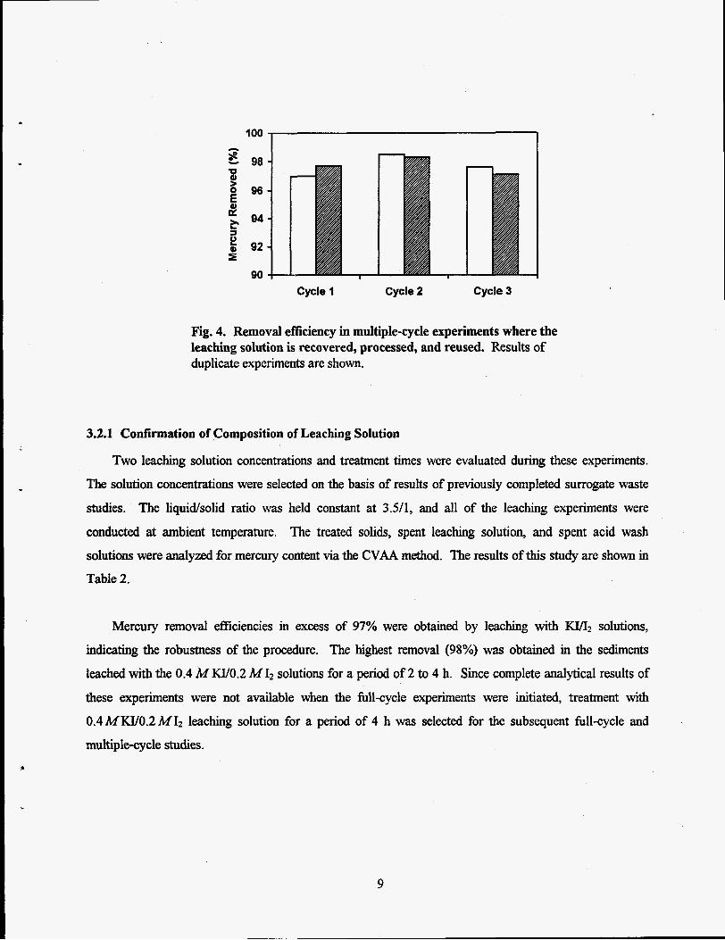
Fig. 4. Removal eficiency in multiple-cycle experiments where the leaching solution is recovered, processed, and reused. Results of duplicate experiments are shown.
3.2.1 Confirmation of Composition of Leaching Solution
Two leaching solution concentrations and treatment times were evaluated during these experiments.
The solution concentrations were selected on the basis of results of previously completed surrogate waste
studies. The liquidsolid ratio was held constant at 3.54, and all of the leaching experiments were
conducted at ambient temperature. The treated solids, spent leaching solution, and spent acid wash
solutions were analyzed for mercury content via the CVAA method. The results of this study are shown in
Table 2.
Mercury removal efficiencies in excess of 97% were obtained by leaching with IU/Iz solutions,
indicating the robustness of the procedure. The highest removal (98%) was obtained in the sediments
leached with the 0.4 MKU0.2 M 12 solutions for a period of 2 to 4 h. Since complete analytical results of these experiments were not available when the full-cycle experiments were initiated, treatment with
0.4MWO.2MI2 leaching solution for a period of 4 h was selected for the subsequent full-cycle and
multiple-cycle studies.
9

Table 2. Evaluation of various leaching conditions for treatment of Y-12 storm sewer sediments
Treatment Initial mercury Final mercury Mercury Leaching solution time concentration' concentration removal
DIW control 4 34,900 16,477 53 1.0MKVO.l MI2 2 34,900 1 .o M Kvo. 1M 12 4 34,900
1,038 97 909 97
0.4 M K V O .2 M 12 2 34,900 686 98 0.4MKV0.2MI2 4 34,900 848 98
"Initial concentration based on average of triplicate samples. bDIW = deionized water.
In both the leaching solution optimization and the hll-cycle experiments (see below), significant
reductions in mercury concentration occurred in the deionized water control studies. Such results were
unexpected since less than 5% mercury reduction was observed in controls in previous studies with
surrogates. However, this apparent reduction in mercury may be the result of retention of the small- particle size fraction of the storm sewer sediment in the filter after leaching has been completed. The data
indicated that, on average, 0.5 g of storm sewer sediment was lost during this step. If these small-sized
particles also contained high concentrations of mercury, then removal of this fraction in the filter would
result in an overall decrease in the mercury content of the bulk solids.
3.2.2 Full-Cycle Experiments
During this study, storm sewer sediment was treated and the spent leaching solution was processed to
remove the solubilized mercury and to recover iodine. After 10-g portions of storm sewer sediment had
been leached with 0.4 M W 0 . 2 M I2 solution for 4 h, the treated solids were first rinsed with water and
then washed with an HzS04-acidified (pH 2.5) solution. The treated and washed solids were subsequently
analyzed for mercury content.
The spent leaching solution was processed to remove the dissolved mercury by contacting the solution
with approximately 4 g of steel wool at a temperature of 50°C for 1 h. After the leaching solution had been
decanted from the steel wool, 0.5 g of lime was added to the solution to precipitate any dissolved metals.
The resulting slurry was mixed for 30 min at ambient temperature, and the solids formed during this step
10

were separated from the liquid by filtration. The filtrate was then divided into two equal portions, and 2.2
mL of concentrated sulfuric acid and 2.2 mL of hydrogen peroxide (30%) were added to one of the
portions. The addition of these reagents resulted in the formation of iodine solids that were then collected by filtration. The results of the full-cycle experiments are summarized in Table 3.
Table 3. Results of full-cycle leaching of Y-12 storm sewer sediment'
Final mercury Mercury Leaching solution concentration removed
(m&) (%) DIW control 2 1,900 37 DIW control 21,800 37 0.4MKU0.2MIz 995 97 0.4 M W0.2 A4 12 536 99
"Duplicate experiments shown.
The mercury concentrations in the treated and washed storm sewer sediment samples from this study
were similar to those measured in samples treated during the leaching solution optimization experiments.
As was observed in the earlier surrogate waste laboratory studies, small volumes of leaching solution were
not completely recovered in several of the stages required for the full-cycle treatment. The volumes of
liquid recovered after the different treatment stages are summarized in Table 4. The average volume of
solution lost during the process (i.e., retained on the filters, in the steel wool, or in the solids leaving the
system) was 21 mL, or 30% of the o r i g d spent leaching solution volume (including the first wash water).
Table 4. Liquid inventory following KI& leaching
Volume collected leaching solution after initial Volume collected CaO addition (d)
Volume of Volume collected
Leaching solution and wash water filtration and after steel wool added w a s h g (mL) (A)
DIW control 70 60 56 48 DIW control 70 65 62 54 0.4MW0.2MI2 70 69 55 49 0.4MK.VO.2MI2 70 68 54 46
8
11
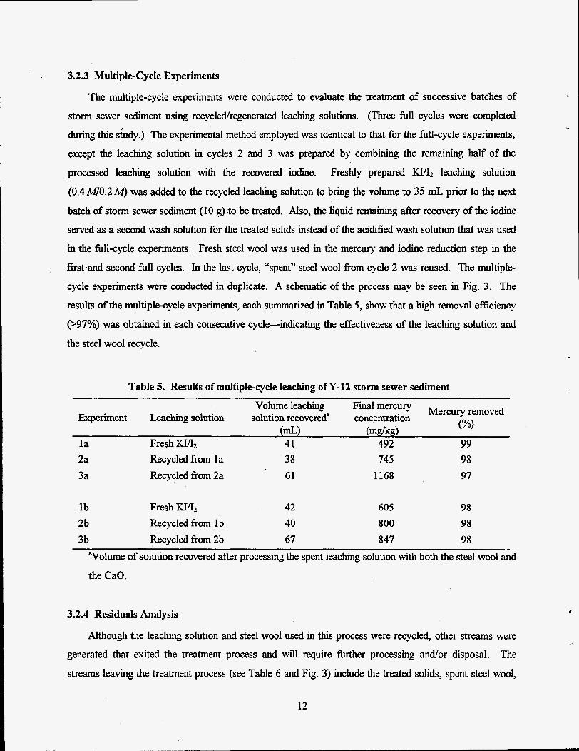
3.2.3 Multiple-Cycle Experiments
The multiple-cycle experiments were conducted to evaluate the treatment of successive batches of storm sewer sediment using recycledregenerated leaching solutions. (Three fill cycles were completed
during this skdy.) The experimental method employed was identical to that for the fill-cycle experiments,
except the leaching solution in cycles 2 and 3 was prepared by combining the remaining half of the
processed leaching solution with the recovered iodine. Freshly prepared KVI, leaching solution
(0.4MO.2M) was added to the recycled leaching solution to bring the volume to 35 mL prior to the next
batch of storm sewer sediment (10 g) to be treated. Also, the liquid remaining after recovery of the iodine
served as a second wash solution for the treated solids instead of the acidified wash solution that was used
in the fill-cycle experiments. Fresh steel wool was used in the mercury and iodine reduction step in the
first and second full cycles. In the last cycle, “spent” steel wool from cycle 2 was reused. The multiple-
cycle experiments were conducted in duplicate. A schematic of the process may be seen in Fig. 3. The
results of the multiple-cycle experiments, each summarized in Table 5 , show that a high removal efficiency
(>97%) was obtained in each consecutive cycle--indicating the effectiveness of the leaching solution and
the steel wool recycle.
Table 5. Results of multiple-cycle leaching of Y-12 storm sewer sediment
mercury Mercury removed Volume leaching
(%I Experiment Leaching solution solution recovered“ concentration
l a Fresh KIA2 41 492 99 (mL) (mgflrg)
2a 3a
Recycled from la Recycled fiom 2a
38 61
745 1168
98 97
l b Fresh KVI, 42 2b Recycled from 1 b 40 3b Recycled from 2b 67
“Volume of solution recovered after processing the spent leaching solution with both the steel wool and
the CaO.
605 98 800 98 847 98
3.2.4 Residuals Analysis
Although the leaching solution and steel wool used in this process were recycled, other streams were
generated that exited the treatment process and will require firther processing and/or disposal. The
streams leaving the treatment process (see Table 6 and Fig. 3) include the treated solids, spent steel wool,
12
c

and Fe(OH), sludge. The spent acid wash solution is actually used as the wash water and will not be a
waste. The characteristics of these streams were determined to provide data that may be required for
evaluating the full-scale application of this technology.
Table 6. Estimation of secondary waste volumes from the leaching process when treating 10 g of solids
Moisture content (%) PH
Amount generated each cycle Stream Matrix
Treated solids Solid 10.8 g 6 12 Fe(OH)2 sludge Solid 3.3 g 11 78 Steel wool Solid NIA" - - Acid wash Liquid 24 mL 1 -
"Steel wool (4 g, initially) can be reused for multiple cycles.
All solids leaving the treatment process [treated storm sewer sediment, Fe(OH)2 sludge, and spent steel
wool] were analyzed using TCLP in addition to direct determination of the mercury content of the solids.
The TCLP extracts were digested using aqua regia and analyzed for mercury content using the CVAA
method. The liquids exiting the treatment system were also analyzed using the CVAA method. The results of the residuals analysis are summarized in Table 7. As is noted, the treated solids contained high levels of
mercury (Le., high enough not to pass TCLP testing). It is likely that a second leaching step or more
effective washing could improve this performance. It is also interesting to note that the iron oxide sludge
after the third cycle contained high levels of mercury, which can be explained if one assumes that the
reduction with recycled iron (steel wool) did not work properly. It is, however, likely that the mercury
concentration of this stream will be sufficiently high to mandate that it must be handled as a hazardous
Waste.
3.3 MATHEMATICAL MODELING OF THE LEACHING PROCESS AND PREDICTION OF WASTE RESIDUALS
The generation of secondary waste can be estimated with good accuracy by reviewing the process
described in Fig. 3 as a black box. The following global mass balance can be performed on treating 1 kg of
contaminated soil, assuming complete recycle of the wash water.
13

Table 7. Mercury concentrations in residuals from KT/12 leaching of storm sewer sediment
Experiment Waste identification Phase
Storm sewer sediment Multiple-cycle 1 b Multiple-cycle 2b Multiple-cycle 3b Multiple-cycle 2a Multiple-cycle 3a Multiple-cycle 2b Multiple-cycle 3b Multiple-cycle la Multiple-cycle 2a, 3a Multiple-cycle 1 b Multiple-cycle 2b, 3b Multiple-cycle 2a Multiple-cycle 3a Multiple-cycle 2b Multiple-cycle 3b
Untreated Treated solids Treated solids Treated solids
Fe(OI-I)2 sludge Fe(OH)2 sludge Fe(Ow2 sludge Fe(OW2 sludge
Steel wool Steel wool Steel wool Steel wool
Spent acid wash Spent acid wash Spent acid wash Spent acid wash
Solid Solid Solid Solid Solid Solid Solid Solid Solid Solid Solid Solid
Liquid Liquid Liquid Liquid
Mercury concentration
(solid-mgkg) (liquid-m&)
34,900 605 800 847
6 566
8 966
7,912 1,591 7,405
40,65 1 45
106 41 45
TCLP extract concentration
(m&) 2.9 8.2 6.2 9.1 0.3 1
28.3 0.41
48.3 Not measured Not measured Not measured Not measured
45 106 41 45
Incoming streams
1. One kilogram of soil with a known moisture content (e.g., 15%) and mercury concentration (e.g.,
1000 mg/kg) is being treated. EquationsNariables:
M, = amount of untreated soil = 1 kg W, = moisture content = 0.15 kgkg Hg, = mercury concentration = 1 gkg
2. Enough iron metal is needed to reduce all the 12 to I- and Hg2+ to Hgo in the leaching solution. The
process calls for 3.5 L (or kg) of 0.2MI2 per kg of soil. Thus, at least 0.7 mol iron, or 0.039 kg, is
required. EauationsNanables:
LS = liquidsolid ratio in leaching step = 3 S kgkg L = amount (kg) leaching liquid = LS x M, 12 = concentration of iodine in leaching liquid = 0.2 M KI = concentration of potassium iodide in leaching liquid = 0.4 A4 MFe = amount (kg) iron needed for reduction = MWF, x (M, x HgJh4Wa + I2 x L)/lOOO
14

3. Calcium oxide is added to precipitate the iron that is dissolved in the iodine reduction step. We will
4 need 0.7 mol CaO, or 0.039 kg, to precipitate the iron as either Fe(OW2 or FeOOH. In practicality,
we need slightly more because the pH needs to be increased from neutral to about 10, but the extra
amount is small. Equatioflariables:
Ma0 = amount (kg) calcium oxide needed for precipitation = MWao x MFa/PVn;Ye
4. Hydrogen peroxide and sulfuric acid need to be added to reconvert half of the iodide in the system to
iodine. We need 1 mol H202 and 1 mol HZSO.4 to make 1 mol 12. Thus, we need 0.07 kg of 98%
H2SO4 and 0.079 kg of 30% H202 to generate the 0.7 mol I2 we need. EauationsNariables:
L%02 = amount (kg) 30% hydrogen peroxide needed = MW30, x I2 x L/( 1000 x 0.3) L%so4 = amount (kg) 98% sulfuric acid needed = MWH2s04 x 12 x L/(lOOO x 0.98)
Outgoing streams
1. Treated soil with a moisture content (e.g., 40%) is being generated. The water in the soil contains low
levels of iodine and iodide as well as mercury, depending on the number of internal washes. The
weight of the treated soil in the case of 40% moisture is 1.42 kg. EauationsNariables:
W, = moisture content in the treated soil = 0.4 kgikg M, = amount (kg) treated solid = M, x (1 - Wus)/( 1 - W,)
2. In the conceptual process, the separated elemental mercury is not removed from the system after each
batch. Instead it is removed intermittently; however, for the purpose of demonstration, let us assume that it is removed after each batch (0.001 kg mercury). EquationsNariables:
M H ~ = amount (kg) mercury removed = M, x HgJlOOO
3. Iron hydroxide/oxide is generated (0.7 mol) as a result of the precipitation. If this sludge has a moisture content of 40%, the amount is 0.1 kg. EauationsNariables:
WF~O = moisture content in iron oxidehydroxide = 0.4 kgkg MFa = amount (kg) of iron oxide/hydroxide generated = (Mw,,,, + M'WF-H) x M~d(2 x W F e x (1 -wFeO))
4. As CaO and H2S04 are added to the system, Cas04 (gypsum) is formed in a stochiometric amount (0.7
mol). If the water content is 40%, we will obtain 0.16 kg. EauationsNariables:
Wwo4 = moisture content in gypsum = 0.4 kgkg Mwo4 = amount (kg) gypsum formed = W-0, x Mad(MWcao x (1 - wca~o,))
In addition to the above-mentioned incoming and outgoing streams, water is added to the process through
the incoming soil, sulfuric acid, and hydrogen peroxide; water is lost in the treated soil, hydroxide sludge,
15

and gypsum sludge; water is generated in the conversion of iodide to iodine; and water is consumed in the
iron hydroxide precipitation step. To make the mass balance complete, the water balance must be satisfied,
and in the example above, 0.45 kg of water must be added to the system. EquationsNariables:
The effectiveness of the soil washing steps after the leaching determines the remaining concentration
of mercury in the soil. If, in the above example, we forego washing, the amount of mercury in the soil after
leaching would be equal to 110 mgkg [or Hg, x M, x WJ(L + M, x W,)]. If the leached soil is washed
twice using M, x LS kg wash liquid, the mercury concentration would decrease to 2.4 mgkg in which case
the treated soil would pass TCLP testing even after drying. The number of washes is also important since some iodine and iodide are lost with the treated solids if washing is not effective. The global mass balance is summarized in Table 8.
Table 8. Constituents of streams in the leaching process as calculated by a simple global mass balance
Incoming streams Outgoing streams Soil, 1 kg Fe, 0.039 kg CaO, 0.039 kg H202 (30%), 0.079 kg HzS04 (98%), 0.070 kg Water, 0.45 kg
Soil, 1.42 kg Fe(OH)2/FeOOH, 0.10 kg CaS04 0.16 kg Mercury, 1 g
The gypsum has been listed as a separate secondary waste stream. However, in practicality, this
stream is always combined with either the soil or the iron oxidehydroxide stream, depending on what is
used as the initial wash liquid. In addition to the global mass balance, a detailed mass balance was
performed to provide more details about the internal process streams (see Appendix A).
3.4 FATE OF RADIONUCLIDES IN THE LEACHING PROCESS
Determination of the fate of radionuclides, specifically uranium, in the leaching process was evaluated
using both surrogate and actual waste.4 Approximately 90% of the soluble uranium present in the leachate
.
16

was removed during the iodindmercury reduction step. This was proven both in surrogate studies using
233U tracers and in actual waste studies using mercury-contaminated tank sludge. An additional 57% of the
remaining soluble uranium was removed in the metals precipitation step. Thus, it was concluded that most
of the uranium will be commingled with the elemental mercury recovered from the process.
In studies conducted with Building 9201-4 tank sludge waste that contained both uranium (44 mgkg)
and mercury (5900 mgkg), only a fraction (1 to 11%) of the uranium was soluble in water or in KVI;!
leaching solution. It is a safe assumption that wastes (such as tank sludges) previously in contact with
water for a long time will contain little soluble uranium.
3.5 ASSESSMENT OF DOCUMENTATION NECESSARY TO CONDUCT A MERCURY
LEACHING DEMONSTRATION ON THE OAK RIDGE RESERVATION
General Electric's mercury removal process has been investigated for the treatment of U.S. Department of Energy (DOE) solid mixed waste that is contaminated with mercury. As previously
described, this treatment process uses a potassium iodide-iodine leaching solution to selectively remove
mercury. It is possible that the technology development may lead to a leaching demonstration on the ORR. Included is an example of a planning document (Appendix B) used at the K-25 Site to collect information
for site support for demonstrations. This document may be used as a guide to successhlly to conduct
various demonstrations with complete regulatory compliance. Of course, minor modifications might be
needed to reflect more current regulatory requirements.
ho ther key document was prepared by Jolley et aL6 Even though this summary/assessment was
prepared for use with a specific project, it may be used as general guidance in determining which reports,
procedures, permit applications, and proposals, etc., are necessary to initiate any type of demonstration
activity conducted on the ORR. The content of this document is summarized below.
3.5.1 Required Proposals and Plans
The primary purpose of the Demonstration Proposal document is to specify the objectives of the
demonstration, to define its scope, and to state the h d i n g requirements. It is important that the objectives
of the demonstration contain a clear statement of the goals and identlfy the customer. Other factors to be
considered during the development of the proposal are (1) to determine whether private vendors will be '
contracted for conducting the demonstration, (2) to determine where the demonstration will be conducted, (3) to prepare formal funding request documentation (Technical Task Plan, Activity Data Sheet or Field
17

Work Plan, etc.) and, finally, (4) to obtain signature approval for the demonstration proposal from line
management Energy Systems (ES) representatives, ES Site Demonstration Manager, Central Waste
Management Director, Environmental Director, ES Central Management, DOE Site Manager, and Waste
Management representatives.
During all stages of the demonstration activity, communication with ORR sites and DOE
representatives is important. The principal investigator and appropriate staff should also interface with ES sites; the ES Site Demonstration Manager; the Waste Research and Development Coordinator; the ES Site
Environmental Coordinator; ES senior management; ES division, programs, or groups (especially the
Central Environmental RestoratiodWaste Management organization); DOE/OR; and the DOE Site
Manager.
3.5.2 Project Description
The Project Description is an extension of the basic document prepared for the original funding
request. It contains information such as objectives of the project; scope of the project; background and
rationale; project organization; preliminary studies; site descriptions; system design; site requirements;
waste generation and disposal of anticipated waste streams; references to health and safety plans;
references to quality assurance plans; permitting issues, including the National Environmental Policy Act
(NEPA), Toxic Substances Control Act (TSCA) demonstration permit, Resource Conservation and
Recovery Act (RCR4) demonstration permit or a Research, Development, and Demonstration (RD&D) permit; and legal issues.
3.5.3 The Project Plan
This plan provides the basis for coordination of all parts of the demonstration. It contains such
information as background and purpose; funding baseline; data to be generated (including analytical,
physical, treatability, and secondary waste data); project approach; permitting issues and appropriate
information to obtain permits; references to an emergency plan; mobilization; an outline of the steps
comprising the demonstration (including schedules, chains of command, site restoration, etc.); projected
radiological controls, if necessary; references to safety and h d t h plan@); readiness review process and
documented approvals; procedure to be used for closeout of the demonstration; references to a final report
detailing results and problems; planned subcontracting and estimated costs; and ground rules for change.
The Project Plan should include the following subsections: the Task Schedule and Financial Plan,
18
5

Regulatory Compliance Plan, Quality Assurance Plan, and Readiness Review Plan. Altemtively, these
plans may be issued as separate documents for approvals.
3.5.4 Task Schedule and Financial Plan
This plan identifies all the tasks that are involved in order to accomplish the goal(s) of the
demonstration and details their initiation and duration. The timing relationship among tasks must be
mapped and milestones set so that progress on the project can be measured. This timing relationship will
develop the critical path that should be highlighted and discussed with members of the demonstration team.
Estimated costs should be identified for each task, thus ensuring supporting facts to defend the budget.
3.5.5 Regulatory Compliance Plan
This plan reviews all of the compliance issues and covers the development of all necessary permits and
permit modifications. Some of the issues that must be examined include compliance with the Waste
Management Plan generated for the demonstration; State, U.S. Environmental Protection Agency (EPA),
RCRA, and RD&D permits or treatability exclusions (Tennessee state limits currently allow 1,000 kg for
each treatability study but has allowed variance in the past and will allow 10,000 kg per technology to be
studied); state air emissions permits; site National Pollution Discharge Elimination System permit
modifications; and a recorded DOE-signed NEPA decision document (such as a Categorical Exclusion
Determination (CXD), a Finding of No Significant Impact, or a Record of Decision). Previous experience
has shown that demonstrations of the type under consideration (soil washing to remove mercury) typically
receive a CXD. Unless the waste to be treated in the demonstration contains polychlorinated biphenyls
(PCBs), a TSCA permit is not required. A TSCA permit for treating more than 250 kg of PCB-
con taminated (more than 50 mg PCB per kg) material is granted by the EPA Headquarters.
The regulatory compliance staff located at the ORR site chosen for the demonstration will be involved
in decisions regarding which permits are necessary and which existing permits need modifications. It is important that communication with the compliance staff is initiated early during the developmental stages
of the demonstration.
3.5.6 Quality Assurance Plan
This plan will include quality procedures, work plans, reports, and documentation. Quality control
should be asserted through routine surveillance and on periodic audits.
19

3.5.7 Readiness Review Plan
This plan, or section, may include responsibilities, activities, required approvals, and the methods by
which these approvals are obtained and documented. (Often, for small demonstrations, a readiness review plan may be no more than one or two pages attached to the project plan.)
3.5.8 Waste Management Plan
This plan should include schemes for the handling and treatment of the waste to be treated during the
demonstration, the treated waste residues, and the materials and equipment wastes generated from the
demonstration.
3.5.9 Site Safety and Health Plan
The Site Safety and Health Plan should include topics such as industrial hygiene regarding the safe
demonstration of operations relative to Occupational Safety and Health Administration (OSHA) site
control to limit the potential of employee exposure to radiological hazards. In general, this document will
supply information regarding personal protective equipment required for work, the necessary industrial
safety and hygiene controls required and their application to various activities, and radiological controls to
be enforced at the demonstration site.
3.5.10 Emergency Plan
This plan must include responders (shift superintendents, fire responders, emergency squad, etc.) and
must state that the responders are required to have orientation training on the demonstration prior to
-P*
4. CONCLUSIONS AND RECOMMENDATIONS
The experiments with surrogate waste and actual storm sewer sediment waste revealed that KI&
leaching solutions can be used to reduce mercury concentration in such waste by as much as 99%. It is
capable of leaching all species of mercury. Since the initial mercury concentration in these wastes is so
large, the treated solids have an appreciable mercury content even with 99% mercury reduction. There are
several possible sources of mercury in the treated solids, including
c
i
entrained leach solution containing high concentrations of soluble mercury, and
mercury that may be trapped in inaccessible spaces within the solid matrix that may not have been
contacted by the leaching solution.
In addition to having appreciable mercury concentrations, the treated storm sewer sediment did not
pass TCLP standards. The mercury levels in the TCLP extracts exceeded the regulatory level of 0.2 mg/L
by at least 60 times. If the entrained leaching solution could be removed, the treated solids might pass
TCLP standards since the soluble mercury concentration in the entrained leach solution is very high
(approximately 5000 mg/L).
The degree of mercury removal achieved may be sufficient if the K I A 2 leaching process is to be used
as a pretreatment process to thermal treatment or stabilization. If however, the process is to be used as a stand-alone treatment, fbrther development and modifications would be required before this process would
be feasible. Areas to consider for development andor modification are as follows:
improve liquid and solid separation steps both to decrease mercury levels in treated solids and to recover more of the leaching solution for regeneration, thereby decreasing the amount of makeup KI/I2
solution required for each treatment cycle; and
evaluate multiple leaching (two or three successive leaching steps) or increased washing of the solids
to determine if lower mercury concentrations can be reached.
Mathematical modeling was used to predict the amount of secondary waste in the process. The global
and the detailed mass balances corresponded very well. The stabilization of this waste, which is generated
at a rate equal to 270 kg per 1000 kg of treated material, remains to be studied.
Both surrogate waste and actual waste were used to study the fate of uranium in the leaching process. Soluble uranium in the solids was transferred to the leaching agent. Ninety percent of this uranium was
removed in the iodine reduction step, while an additional 6% was removed in the metals precipitation step.
Thus, uranium will contaminate the mercury recovered and, to a lesser extent, the other secondary wastes.
21

5. REFERENCES
1. N. I, Sax and R. J. Lewis, Sr., Hawley’s Condensed Chemical Dictionary, 11th ed., Van Nostrand
Reinhold Company, New York, 1987, p. 745.
2. Lunge’s Handbook of Chemism, 13th ed., ed. J. A. Dean, McGraw-Hill, New York, 1985, pp. 5-71.
3. D. D. Gates, K. K. Chao, and P. A. Cameron, The Removal of Mercury from Solid Mixed Waste
Using Chemical Leaching Processes, ORNL/TM-12887, Martin Marietta Energy Systems, Inc., Oak
Ridge National Laboratory, TN, July 1995. 4. W. D. Bostick, W. H. Davis, and R. J. Jarabek, Fate of Soluble Uranium in the IdKI Leaching
Process for Mercury Removal, IUTSO-55, Lockheed Martin Energy Systems, Inc., East Tennessee
Technology Park, TN, September 1997.
5 . Development and Use of EPA ’s Synthetic Soil Matrix, U.S . Environmental Protection Agency, Release
Control Branch, Risk Reduction Engineering Laboratory, Edison, N. J., February 1989.
6. R. L. Jolley, M. I. Moms, and S. P. N. Singh, Guidance Manual for Conducting Technology Demonstration Activities, ORNLEM-11848, Martin Marietta Energy Systems, Inc., Oak Ridge
National Laboratory, TN, December 199 1.
22

Appendix A DETAILED SPREADSHEET CALCULATIONS FOR THE KI& LEACHING PROCESS


Watermakeup i 0.20L t
PotasJiumiodide 9.5g 7.2g
Soil soil b WASH l500g
soil
10% moisture 1000 ppm mermry
lO0Og MERCURY LEACHING .. .............* 40% moisture
16.26 ppm mercury A
....................................... t .......................................................... spentwashwater i f 3.50L 3.50L
Leachate f 3.00L i
v v 9 Water makeup ................................... f Leaching solution 0.29L
b i Iron 12 AND Hg i 3.30L
38.lg REDUCTION
4 Iodine recycle Mercury /6.50L I 284g j Water recycle
0.9768. i3.21L v i3.19L
................... .................................. b r OXIDATION calcium METALS :
4 4 oxide PRECIPITATION 3.19L 41.9g
Metals sludge Hydrogen I i s w c peroxide (30%) i acid (98%) 272g
40% moisture 0.07L 0.06L 0.02 ppmmercury
Summay Flow Sheet of the Leaching Process

Unit Operation A: Sofl leaching
Conventlons: Red - Letters - parametem deanition; numbers - prsnmed values Blue = formuIa/equatlons; dcuIated value Balance Units = buIkliquid {L); bulksolid (g); Individual chemic& (mol) Assume that d fllter Eakes contain the same wt% of liquid.
Calculation basis: Treat WW 1 (wet weight) {g} Hgcontaining wet soils, which contain5 C-Hg {ppm} of Hg and XX1 {wt%} of water. W W l = 1000 C-Hg= 1000 XX1= 10%
LVl = Liquid volume {liter} used to leach soil LVlNW 1 = 3.5*E3 LVI =(3.5*E3)*WWl
Assume M(2 leaching mved&ciency xx2= 1 .oo 12 + Hg + 2 r --> H&'-
Bulk balance: !$ LV2 = LVl + (wwl*xxlylooo {L}
w w 2 = WWl+(l-xxl) (9)
Balance in soil WW2: Unleached Hg: MS2 = WW 1 *C~H@(1/1000)+(1/1000)*( lnOO.59)*( 1-XX2) {mol}
Balance in liquid LK?: Hg: ML2 = WW1*C~H@(1/1000)*(1/1000)*(1/200.25)*xx2 (mol} Iodine, 12: IODINE2 = LV1*0.2 -ML2 (mol} Iodide, E IODIDE2 = LV1'0.4 - 2 * W {mol}
,
Lepehing liquid9 LV1 3.5 {L}
12, IODINE1 : 0.7 {mol} KI, IODIDE 1 : 1.4 {mol}
(WI, = 0.4WO.2M)
Liquid9 LV2 12, IODINE2: KI, IODIDE2: H h 2 - , ML2:
3.6 {L) 0.695014707 {mol} 1.390029413 {mol} 0.004985293 {mol}
(Assume DENSITY1 =water dennsity) i.e. 1000 @iter
Drysoil,WWZ= 900 H a G , MS2 0

Unit Operation B Filtration of leached soils
Assume that the filtered soil contains XX3 (wt%} liquid and density of the leaching liquid LV2 is DENSITY2 {giter} XX3= 40% DENSITY2= 1000
Bulk balance: w w 3 = w w 2 +XX3*WW2/(1-XX3) {g} LV3 = LV2 - WW3*XX3/DENSITY2 {liter}
Balance in wet solid WW3: Hg : Iodine: IODINE3S = WW3*XX3*( liDENSITY2)*(IODINE2/LV2) Iodide: IODIDE3S = WW3*XX3*( IiDENSITY2)*(IODIDE2/LV2)
MS3 = MS2 +WW3*XX3*(l/DENSITY2)*(ML2/)
Balance in liquid LV3: Hg: Iodine: Id&
M U = ML2 - WW3*XX3*(I/DENSITYZ)*(MLZ/LV2) IODINE3L = IODINE2 - IODINE3S IODIDE3L = IODIDE2 - IODIDE3S
Balance in LV5: LV5 = Lv3 4- LV4 Hg: M W = M U + M U Iodine:
S u K e
IODINE5 = IODINE3 + IODINE4 ' Iodide: IODIDE5 = IODIDE3 + IODIDE4 SF4 = CA = FEU
Liquid, Lv3 Hg, ML3:
T
Wet SOU, WW3 1500 (91 Hg in dry soil, MSS3: 0 {mol} Hg in retained liquid, MSU: 0.00083 1 {mol) Total Hg, MS3: Iodine, IODINE3S: Iodide, IODIDE3S:
0.00083 1 imolj 0.115836 {mol} 0.231672 {mol}
r 3 {L} 0.004154 {mol}
Iodine, IODINE3L 0.579179 {mol} Iodide, IODIDE3L 1.158358 {mol}
Unit B - Filtration

Unlt Operntlon C Wash the Ienched mil nlth H2S0,-t&S04
Assumption: Sulfhie conCentration in LV15 should be controlled to give a sulfate concentration in LV4 liquid same as the calcium concentration in LV7 liquid, i.e., SF4 = CAYSEE Unit F) Required moles of sulfate SFl5 to match the total Ca2’ moles SFl5 = SF4/(1-((WWPXXf7DENSITY17)/LV17)) (Assume liquid content in final wet soil mwt?h} = 40% )
Forthe f~ cycle, assumethat LVl5 (liter}/WW3 {g} = 3.5%-3 (For later cycles, LVlSnew) WWf = w w 3 LV17 = WW3*XX3/DENSITY2 + LVlS = WWPXXtlDENSITY17 + LV4 IODINEf = IODINE3S*((WWPxxDaENSITYl7)’LVl7)
SF4 = CAL SFlS = SF4/(1-((WWPXXt7T.lENSJTYl7)LVl7)) In order to match the moles of CaZt, the sulfate concentration in Liquid LVlS should be controlled around SF-CONC = SFl5LVlS
DENSITY17 {gfliter} = 1000
(Approximation: LV4=LV15, WWf= WW3)
IODINE4 = IODINE3S - IODINEfz IODINE3S(l-((WWPXXf7DENSITYl7yLV17))
Bulk balance:
LV17 = WW3*XX3DENSITY2 + LVl5 LVlS = (3.5*E(-3))*WWl {L)
WW17= WW3*(1-XX3) (drywt.g) {L}
w 00 Balance in wash liquid LVlS:
Sulfate: SFl5 = SF4/(1-((WWPXXi7DENSITYl7)/LVl7))
Balance in LV17 Hg: ML17 = M U +ML15 (Assume that MLI 5 = Iodine: IODINE17 = IODINE3S Iodide: IODIDE17 = IODIDE3S Sulfate: SF17 = SF15
Balance in dry soil WW17 Hg: MS17 = MS2
0 for the fust cycle) trace forlatercycles
Unit C - Wash
1 1
WWf 1500 LV17 4.1 IODINEf 0.016952 IODINE4 0.098884 5f4 0.747927 SFlS 0.876143
1 I

LVl5nerr 3.21394 {L} SF15new 0.648548 {mol} MMl5new 9.23E-07 {mol}
Water/sulfate makeup needed for washing Water, LVsm: 0.28606 (L} Sulfuric acid, SFsm: 0.204668 {mol} OT
Wash liquid, LVl5 3.5 {liter} Sur&, SF15: 0.87614286 {mol} The sulfate c o n d o n needs to be adjusted to: SF-CONC 0.250327 {molditer}
I Llquid, LV1 4.1 {Ll Hg, ML17 0.00415441 {mol} Iodine, IODINE17 0.11583578 {mol} Iodide., IODIDE17 0.23167157 {mol} Sulfite, SF17 0.87614286 {mol}
Dry soil wt, WW17 * 900 Hg, MS17 0
0.013645 {L)
unitc-wash

unit D mrntlon of washed sou8
Assumption: The final soil cake contains XXf {Wh) of liquid LV17. (see Unit C sheet for value assignment) (for the fvst cycle, there is no Hg in wash liquid LV15; thus, ML15 4, see Unit C sheet)
Soil wet weight WWf = WW3 Soil dry weight DWf= WW3*(1-XXf) Unleached Hg in dry soil: Hg in retained liquid Total Hg in the wet soil: Iodine: IODINEf = IODINE3S*WWfzxxf*(l/DENSITY17)ILV17 Iodide: IODIDEf = IODIDE3S*WWfz~(l/DENSITY17)/L.V17 Sulfate: SFf = SF17*WWf*XXf*(l/DENSITYl7)&Vl7
MSSf = MS2 MSLf= WWPXXP(l/DENSITY 17)*((MSU+ML15yLVI7) MSf = MSSf + MSLf
LV4 = LV17 - WWfzxxm)ENSITY17 Hg: M U = MSJ.3 - MSLf I d i e : Iodide: Sulfak SF4 =CAL
IODINE4 = IODINE17 - IODINEf IODIDE4 = IODIDE1 7 - IODIDEf
w 0
SF1 7 -SFf =SF4
___+
Soil dry weight, DWf 900 {Id Unleached Hg in dry soil, MSSP 0 {mol}
Clean soil wet weight, WWf 1500 {g}
Hg in retained liquid, MSIA 0.000122 {mol} Total Hg inthe wet soil, MSf: 0.000122 {mol}
16.26016 {ppm}
Iodine, IODINEf: Iodide, IODIDEf: Sulfate, SFP
Liquld, LV4 3.5 {L} Hg, MLA 0.000709 {mol} Iodine, IODINE4: 0.098884 {mol} Iodide, IODIDE4: 0.197768 {mol} SuW&, SF4: 0.747927 {mol}
SF17 -SR= 0.747927 {mol}
Unit D - Filtration
0.016952 {mol} 0.033903 {mol} 0.128216 {mol}

1
Stream Merge
Balance in LVS: LV5 = Lv3 + LV4 Hg: Iodine: Iodide: Sulfate: SFS = SF4
ML5 = ML3 + ML4 IODINE5 = IODINE3L + IODINE4 IODIDE5 = IODIDE3L + IODIDE4
U I
Merge
Liquid LV3
t
Liquid, LVS 6.5 {L} Hg, MLS: 0.004864 {mol} Iodine, IODINES: 0.678063 {mol} Iodide, IODIDES: 1.356126 {mol} Sulfate, SFS: 0.747927 {mol}
Merge

Unit E 1, reduction and Hg reduction (pH requirement?)
Reduction reactions: Fe + I2 -> Fez' + 2 r Fe + HA2' -> Fe2' + 4 r + Hg
Assume 100% reduction conversion yield, i.e., CONVl= 100% CONV2= 100%
Assume that we supply FE-in 1000 (g} Each cycle consumes Fe: FE = (IODINES*CONVI + MLS*CONV2)*55.85 (g) Fe left unused FE-out = Fe-m - FE {g}
Fe added, FE-h 1000 h-9 Feconsumed, FE: 38.14146 {g)
Amount of soluble Hg reduced into molecular Hg: WWHg = MLS*CONV2*200.59 {g)
Balance in liquid LV6: LV6=LVS (L} Total Fez+ generated: FEU = IODINES*CONVl + ML5*CONV2
IODIDE6 = IODIDE 5 + 2*IODINES+CONVl+ 4*MW*CONVZ Trace amount of molecular Hg lek MM6 = LV6* HG-eql200.59 (mol)
Sulfe . SF6 = SF5
{mol) w Total iodide mol:
(mol)
(Assume HG-eq = 0.00006 (gfliter} )
I L
Unit E - Reductions
I ,
Liquid, LV6
nused, FE-out: 961.8585 (g}
lar Hg produced: g: 0.97561 (g}
r 6.5 {L}
Fe*+generated, FEU: 0.682927 {mol} Iodide, IODIDE6: 2.731707 {mol} Hg, MM6: 1.94E-06 (mol} Sulfate, SF6: 0.747927 (mol}

w w
CaO
4 1.94374 (CAO)
I 6.487707 {L)
0.747927 {mol}
+ Liquid, LV7 ca2+, CAL: 0.747927 {mol} ca2+ + SO,' -> CaSO,(s)
CaS04, SFS: 101.718 {g} Fe(OH)2, FES: 61.46341 {g} Iodide, IODIDE7: 2.731707 {mol}
1.94E-06 {mol} Hg, MM7:
so,", SM:
Unit F pndpit.tion of Fe% to form Fe(0IQ LV6
CaO + H20 + Fez' -> Ca*+ + Fe(OHh(s) Ca2+ + SO,' -> WO,(S)
CaO needed to precipitate Fe2+ : CAO = (FEU + LV6*102)*56.08
Ca2+ produced: CAL = FEU + LV6*102
Total iodide: IODIDE7 = IODIDE6 {mol}
Assume that the Fe2+ precipitation is complete, thus the amount of Fe(0H)I precipitates: FES = FEU'90 {gl
Amount of caso, precipitates: SFS = SF6*136.0 {g}
IODIDE7 = IODIDE6 MM7 = MM6
Compare CAL with SF673 (THEY SHOULD BE THE SAME VALUE)
LV7 = LV6 - LVW (LVW = FEL6*18/1000 l i )
Unit F - Precipitation

Unit G: Filtration of Fe(O€Q and CaSO, sludge
Assume that the filtered cake contains XX8 {wt%) of liquid LV7. XX8= 40% Assume that liquid density of Lv7: DENSITY7 = 1000 giliter
LV7 + sludge
Sludge dry weight: SDW8 = SFS + FES Sludge wet weight:
Total iodide: IODIDE8S = (IODIDE7/L,V7)*(WWS*XU8lDENSITY7) (mol} Trace Hg {mol}: MM8S 5 (MM7/LV7)*(WW8*XX8/DENSITY7)
{g}
WW8 = SDW8 + SDW8*XX8/(l-XX8) {&!I
Balance for liquid LV8:
Iodide. IODIDEBL = IODIDE7 - IODIDEIS LV8 =LV7-W WI*XX8/DENSITY7
Hg: MM8L = MM7-MM8S
- Liquid, LVS 6.37892 {L} Iodide, IODIDE8L 2.685901 {mol} Hg, MM8L 1.91E-06 {mol}
r Sludge cake of Fe(O€Q and CaSO, wet wt, WWI: 271.9691 {g} Iodide, IODIDEIS: 0.045806 {mol} Hg, MMIS: 3.26E-08 {mol}
. 0.024045 {ppm}
Unit G - Filtration
t

Liquid, LV9 3.18946 {L} Iodide, IODIDE9: 1.342951 {mol} Hg, MM9: 9.563-07 {mol}
Liquid, LV8
Liquid, LVlO 3.18946 {L} odide, IODIDEIO: 1.342951 {mol}
9.56J2-07 {mol} Hg, MMIO: I
Stream Spliitmg

Unit H: pH adjustment to pH 3.5 by addition of H2S04 (98%)
H2S0, needed: SFll = LV9*(102/2 + lo’%)
Assume density of 98% sufiric acid DENSITY1 1 = 1500 {@iter} Volume of 99% H2S04 LVI 1 = SF1 1*98*(1/DENSITYll)
Pure H2S04 needed, SFll:
H2S04 (98%), LVll
1 LVl2 = LV9 + LVll Sulfate: SFl2 = SFll Iodide: IODIDE12 = IODIDE9 Hg: MMl2 = MM9
{L}
12 3.190535 {L} Sulfate, SF12: 0.016452 {mol} Iodide, IODIDE12: 1.34295 1 {mol} Hg, MM12: 9.56E-07 {mol}
Unit H - pH Adjustment
I t
0.016452 {mol}
0.001075 {L}

w 4
Unit I: Iodide oxidation at pH 3.5 by addition of hydrogen peroxide
2 r + H202 + H2S04 -> 12 + 2H20 + SO,"
Pureperoxideneeded: PER13 = (1/2)*IODIDE12 {mol} 30% {wt%} peroxide needed: Assume that density of 30% peroxide DENSITY13a= 1100 {fliter} LVper = (1/2)*IODIDE12*34*(1/3O%)*(l/DENSITY 13a} {L)
Pure suffiric acid neededto add: SF13 =(1/2)*IODIDEl2 - SFl2 {mol} Volume of 98% sulfuric acid needed to add LVs = SF13*98/DENSITYl1/.98 {L}
'
Lv13 =LVper + LVS
P
c
30% H&,, LVw: 0.069182306 {L} (Pure H202, PER13: 0.671475326 {mol})
H$SOd(99%), LVS: 0.043668249 {L} (Sulfkte, SF13): 0.655023729 {mol}
0.112850555 {L]
Sulfate, SF14 0.671475 {mol} HgMM14 9.563-07 {mol} Iodine mild IODINE14 0.671475 {mol} w w 1 4 170.4272 {g}dry
LV14 = LV12 + LV13 +LVwa {L} (LVwa = IODIDE12*18/1000) Sulfate: SF14 = SF12 + SF13 {mol} Hg: MM14 = MMl2 {mol} Iodine solids produced : IODINE14 = (1/2)*IODIDE12 {mol}
= IODINE14*253.81 {g} dry
Unit I - Iodide Oxidation

w 00
Hg: MMl5S =(MM~4/LVl4)*WWl5*XXl5/DENSITY15
LVlSnew = LV14 - WWlS*XXlS/DENSITY (L} Sulfate: SFlSL=SFlSnew= SF14-SFl5S (mol}
Unit J: Eutration of iodlne SOU&
Hg, MM15S: 3.26E-08 {mol}
Assume that the iodine cake contains XX15 {wt%} liquid LVlSnew. XXl5 = 40% Assume that the demity of LVI 5 is DENSITY 15 = 1000 {giliter}
(Iodine solubility in water is O.O29g/lOOg water) Wet iodine solid weight:
Iodine: IODINE15 = IODINE14 Sulfate: SFl5S = (SF14/LV14)*WW 1 5*XXl S/DENSITY 15
WW 15 = WW 14*( l+XXI 5 4 1-XXl5)) (g) {mol)
Liquid,LVlSnen 3.21394 (L} SuKkte, SFl5L 0.648548 {mol) (=SFlSnew 0.648548 )
9.23E-07 (mol) (=MM15new 9.23E-07 ) Hg, MM15L T Wet I2 soUds,WWl5 284.0453 (g} 12, IODINE15: 0.671475 {mol} SuKkte, SFISS: 0.022927 {mol}
,
Unit J - Filtration
I
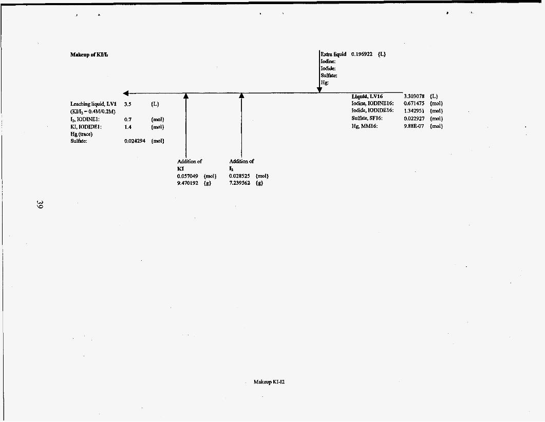
Makeup of KIlL
Leaching liquid, LV1 3.5 {L} ( K Q 0.4WO.2M) 12, IODINE1 : 0.7 {mol} KI, IODIDEI: 1.4 {mol}
Sulfate: 0.024294 {mol} Hg (-4
Iodine, IODINE16: 0.671475 {mol} Iodide, IODIDE16 1.342951 {mol} SuWate, SF16 0.022927 {mol} Hg, MM16: 9.88307 {mol}
Addition of Addition of KI 4 0.057049 {mol) 0.028525 {mol) 9.470192 {g} 7.239562 {g}
Makeup KI-I2


.
Appendix B EXAMPLE OF PLANNING DOCUMENT USED AT THE K-25 S m FOR
DEMONSTRATIONS

.

CENTER FOR ENVIROMMENTAL TECHNOLOGY TECHNOLOGY DEMONSTRATION PLANNING DOCUMENT
OAK RIDGE K-25 SITE
OCTOBER 1994
prepared by Environmental Management Division
Oak Ridge K-25 Site Oak Ridge, Tennessee
43

SUMMARY
The primary mission of the Oak Ridge K-25 Site is to support the missions of the Environmental RestoratiodWaste Management (ElUWM) business unit and other tenants at the site in a safe, reliable and efficient manner. Part of the mission includes hosting technoiogy demonstrations that support ERNCrM activities. The Center for Environmental Technology (CET) was created to faciiitiate the selection and implementation of technology demonstrations. This planning document is intended to provide key information in planning site support for demonstrations that will be conducted at the K-25 Site. It is not intended to provide a comprehensive discussion that addresses all aspects of operating at the K-25 Site. Details on items listing in the planning list should be obtained from the appropriate technical disipiines. In addition, this document does not attempt to define how a demonstration should be managed.
The roles and responsibilities of the various participants involved in the demonstration should be cleariy defined. Potential lead groups/agencies of demonstrations include:
0 Martin Marietta Energy Systems (Energy Systems) personnel, Energy Systems subcontractors, Department of Energy prime contractors,
0 other federal agencies, and 0 prime contractors to other federal agencies.
Contracting mechanisims for conducting demonstration will also vary based on the participants involved in the demonstration. These include contraas, subcontracts, interagency agteements and cooperative research and development agreements (CRADA). The contract@ mechaLljsm and the representives conducting demonstration will have a direct impact on the actions to be taken by the K- 25 Site in planning and supporting a technology demonstration.
Other factors are ais0 important in planning demonstration support. The type and volume of mateTiai to be treated will define the organizations that need to be involved in planning and suppoting demonstration activities. The use of contaminated materWwastes will require more planning than a demonstration using only surrogates (clean material). Hazardous wastes (Resource Conmation and Recovery Act, and Toxic Substance Control Act wastes) may require various types of approvals and notifications, depending on the volume of material to be treated. The level of radioactive con tamhation can affect personal protection and training requirements. Limits exist for the amount of con taminated hazadous waste that can be treated by a technology demonstration; however, there are no reguiatory limits on the amount of surrogate and/or radioactive material that can be treated. Other regulatory drivers may be applied if the material to be treated is a solid waste.
This plannhg guide should be used to determine requirements that may be applicable to a techDology d e m o d o n axxi what additional documentation is required prior to hiththg demonsation activities. This guide can provide usefui information when initiating demoasaatian piannig with various technical disiplines.
44

R
Center for Environmental Technology l’echndogy Demonstration Planning List
Oak Ridge K-25 Site
2. Types of contaminanls
c. Radioactive
d . Mixed (hazardous & radioactive)
e. Solid waste I I 3. Amount of material to be treated I I
I I
4. Regulatory permils
a. RCRA Research, Development 8c Demonstration permit
b. RCRA Part B permit
c. EPA approval for TSCA waste
d. Approval as a pretreatment facility (for water
e. NPDES prmitted discharge point only)
1 10194

P o\
Item or Activity -~ __
f. CERCLA approval (under the Federal
g. Air permitting evaluation (exemption from air
Facilities Agreement for ORR)
permittinglair permit required)
5. Environmental Reyuirements
a. NEPA documentation
b. RCRA accumulation and 90day storage areas
c. Low level waste storage area
d. Use/storage of hazardous materials and/or fuel (gasoline, diesel)
e. Secondary containment for hazardous
f. Monitoring requirements for air emissions
6. Waste Transportation, Storage and Disposal
a. Off site shipment of wastes (to and from
b. Types and numbers of storage containers
c. Disposal of treated and untreated wastes
d. Types and amounts of secondary and
materials and hazardous wastes
K-25)
(bulk vs containers, liquidslsludges/soiids)
personal protective equipment wastes and disposal method
Applicable (Yes/No) Comments
2 10194

d 8 t I V <
P 4
Item or Activity
e. Shipment of analytical samples off site
7. Training
a. General Employee Training
b. 40 hr or 24 hr HAZWOPER
c. 8 hr HAZWOPER supervisory
d. Radiological Worker I1
e. Off road driver training
8. Heallh & Safety
a. Health & Safety plan
b. Safety Work Permit (not required if using a Health & Safety plan)
c. Radiological Work Permit
d. Safety assessment
e. Inspect demonstration equipment for health & safety concerns prior to arriving on site (preferably at vendors facility)
and electrical hazards f. Lock outhag out activitieslprocedures/permit
g. Confined space entry/permit
h. Hoisting and rigging activites
Applicable (Yes/NoI
-
Comments
10/94 3

Item or Activity
i. Elevated work requirements
j. Noise hazards
k. Flammables and combustibles to be used
1. Respirator use/procedures m. Disposal/reusable/laundrable
personal protective equipmentlanti- contamination clothing
n. Personal monitoringldosimetryhioassay 0. Use of cornmessed eas cvlinders
9. Fire Protection a. Fuel/ProPane use and storage
b. Building egress (for demonstrations conducted inside buildings)
~~ ~- ~
c. Hot work/welding/burning permit ~
10. Micellanems Permits, Requests, Approvals, and Notifications
a. merational Readiness Review
b. Excavatlonlpenetration permit (for penetrations >4" In concrete, > 12" in soillasphalt, and for building walls)
Applicable (YeslNo) Comments
4 10194

P W
. . i
Item or Activity
c. Electrical service request (for electrical power, but does not include disconnects)
d. Request for sanitary sewer connection
e. Request for potable water f. Request for discharge of non-contaminated
water (to discharge accumulated water to storm drain)
g. Visitor passes h. Security plans for uncleared visitors in L-
cleared and Q-cleared areas i. Request for Foreign National Unclassified
visit or assignment (for non-US citizens) 1. Notification of PSS/Emergency Preparedness
of start up of operations, MMES contact, and use/storage of hazardous materials
k. K-25 Area Manager (Facility & Property Management Dept.) facility siting approval
1. Export Control lrpproval for mailingkhipping documents & equipment into and out of the us.
m. Road closures required and duration 11. Community Relations/Publieity
Applicable (Yes/No) Comments
I
5 10194

Comments
' I
ul 0
6 10194


![This document is downloaded from the Digital Open Access … · 2020. 2. 18. · less than 10% were in monosaccharide form. Soto et al. [12] were able to solubilize up to 25% of radiata](https://static.fdocuments.in/doc/165x107/6097d5f173883f41341d3c9d/this-document-is-downloaded-from-the-digital-open-access-2020-2-18-less-than.jpg)