3634A 4710 Body - Logic Control Acquisition/x710... · 2009-11-23 · Accessory Description GE MDS...
48
Installation and Operation Guide GE MDS 05-3634A01, REV. B SEPTEMBER 2008 MDS 4710 Data Transceiver For UK-MPT 1411 Applications
Transcript of 3634A 4710 Body - Logic Control Acquisition/x710... · 2009-11-23 · Accessory Description GE MDS...

Inst
alla
tion
and
Ope
ratio
n G
uide
GE MDS 05-3634A01, REV. BSEPTEMBER 2008
MDS 4710
Data TransceiverFor UK-MPT 1411 Applications

QUICK START GUIDE
Below are the basic steps for installing the transceiver. Detailed instructions are given in “INSTALLA-TION” on page 7 of this guide.
1. Install and connect the antenna system to the radio• Use good quality, low loss coaxial cable. Keep the feedline as short as possible.• Preset directional antennas in the direction of desired transmission.
2. Connect the data equipment to the radio’s INTERFACE connector• Connection to the radio must be made with a DB-25 Male connector. Connections for typical sys-
tems are shown below. • Connect only the required pins. Do not use a straight-through RS-232 cable with all pins wired.• Verify the data equipment is configured as DTE. (By default, the radio is configured as DCE.)
3. Apply DC power to the radio (10.5–16 Vdc @ 2.5 A minimum)• Observe proper polarity. The red wire is the positive lead; the black is negative.
4. Set the radio’s basic configuration with a Hand-Held Terminal (HHT)• Set the transmit frequency (TX xxx.xxxx) and receive frequency (RX xxx.xxxx) as authorised by
the station licence.• Set the baud rate/data interface parameters as follows. Use the BAUD xxxxx abc command, where
xxxxx equals the data speed (110–38400 bps) and abc equals the communication parameters as follows:a = Data bits (7 or 8)b = Parity (N for None, O for Odd, E for Evenc = Stop bits (1 or 2)(Example: BAUD 9600 8N1)
NOTE: 7N1, 8E2 and 8O2 are invalid parameters and are not supported by the transceiver.
5. Verify proper operation by observing the LED display• Refer to Table 5 on page 17 for a description of the status LEDs.• Refine directional antenna headings for maximum receive signal strength using the RSSI command.

MDS 05-3634A01, Rev. B MDS 4710 (MPT 1411) I/O Guide i
TABLE OF CONTENTS
1.0 GENERAL ................................................................................... 1
1.1 Introduction ......................................................................................1
1.2 Applications ......................................................................................2
1.3 Model Number Codes ......................................................................3
1.4 Accessories ......................................................................................4
2.0 GLOSSARY OF TERMS ............................................................. 5
3.0 INSTALLATION............................................................................ 7
3.1 Installation Steps ..............................................................................8
3.2 Transceiver Mounting .....................................................................12
3.3 Antennas and Feedlines ................................................................12
3.4 Power Connection ..........................................................................13
3.5 Data Interface Connections ............................................................13
3.6 Using the Radio’s Sleep Mode .......................................................14
4.0 OPERATION.............................................................................. 16
4.1 LED Indicators ................................................................................16
4.2 RSSI Measurement ........................................................................17
5.0 TRANSCEIVER PROGRAMMING ............................................ 17
5.1 Hand-Held Terminal Connection & Startup ....................................18
5.2 Hand-Held Terminal Setup .............................................................18
5.3 Keyboard Commands ....................................................................19
5.4 Detailed Command Descriptions ....................................................22
6.0 TROUBLESHOOTING .............................................................. 30
6.1 LED Indicators ................................................................................30
6.2 Event Codes ...................................................................................30
7.0 TECHNICAL REFERENCE ....................................................... 32
7.1 GE MDS 4710 Transceiver Specifications .....................................32
7.2 Helical Filter Adjustment ................................................................35
7.3 Performing Network-Wide Remote Diagnostics .............................36
7.4 Upgrading the Radio’s Software ....................................................37
7.5 dBm-Watts-Volts Conversion Chart ................................................38

ii MDS 4710 (MPT 1411) I/O Guide MDS 05-3634A01, Rev. B
Copyright NoticeThis Installation and Operation Guide and all software described herein are protected by copyright: 2008 GE MDS, LLC. All rights reserved.
GE MDS reserves its right to correct any errors and omissions.
Operational Safety NoticesThe radio equipment described in this guide emits radio frequency energy. Although the power level is low, the concentrated energy from a directional antenna may pose a health hazard. Do not allow people to come in close proximity to the front of the antenna when the transmitter is operating.
This manual is intended to guide a professional installer to install, operate and perform basic system maintenance on the described radio.
ISO 9001 RegistrationGE MDS’ adherence to this internationally accepted quality system standard provides one of the strongest assurances of product and service quality available.
GE MDS Quality Policy StatementWe, the employees of GE MDS, are committed to achieving total cus-tomer satisfaction in everything we do.
Total Customer Satisfaction in:• Conception, design, manufacture and marketing of our products.• Services and support we provide to our internal and external
customers.
Total Customer Satisfaction Achieved Through:• Processes that are well documented and minimize variations.• Partnering with suppliers who are committed to providing quality and
service.• Measuring our performance against customer expectations and
industry leaders.• Commitment to continuous improvement and employee involvement.
NoticeWhile every reasonable effort has been made to ensure the accuracy of this manual, product improvements may result in minor differences between the manual and the product shipped to you. If you have addi-tional questions or need an exact specification for a product, please con-tact our Customer Service Team using the information at the back of this guide. In addition, manual updates can often be found on the GE MDS Web site at www.GEmds.com.
RF Exposure
MDS 05-3634A01, Rev. B MDS 4710 (MPT 1411) I/O Guide 1
1.0 GENERAL
1.1 Introduction
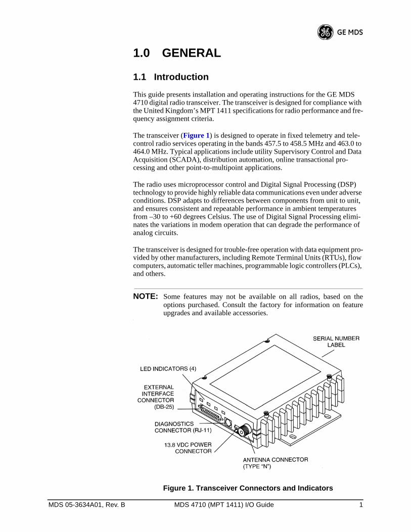
This guide presents installation and operating instructions for the GE MDS 4710 digital radio transceiver. The transceiver is designed for compliance with the United Kingdom’s MPT 1411 specifications for radio performance and fre-quency assignment criteria.
The transceiver (Figure 1) is designed to operate in fixed telemetry and tele-control radio services operating in the bands 457.5 to 458.5 MHz and 463.0 to 464.0 MHz. Typical applications include utility Supervisory Control and Data Acquisition (SCADA), distribution automation, online transactional pro-cessing and other point-to-multipoint applications.
The radio uses microprocessor control and Digital Signal Processing (DSP) technology to provide highly reliable data communications even under adverse conditions. DSP adapts to differences between components from unit to unit, and ensures consistent and repeatable performance in ambient temperatures from –30 to +60 degrees Celsius. The use of Digital Signal Processing elimi-nates the variations in modem operation that can degrade the performance of analog circuits.
The transceiver is designed for trouble-free operation with data equipment pro-vided by other manufacturers, including Remote Terminal Units (RTUs), flow computers, automatic teller machines, programmable logic controllers (PLCs), and others.
NOTE: Some features may not be available on all radios, based on theoptions purchased. Consult the factory for information on featureupgrades and available accessories.
Invisible place holder
Figure 1. Transceiver Connectors and Indicators
2 MDS 4710 (MPT 1411) I/O Guide MDS 05-3634A01, Rev. B
1.2 Applications
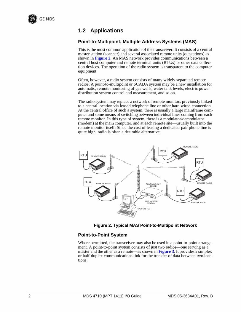
Point-to-Multipoint, Multiple Address Systems (MAS)This is the most common application of the transceiver. It consists of a central master station (scanner) and several associated remote units (outstations) as shown in Figure 2. An MAS network provides communications between a central host computer and remote terminal units (RTUs) or other data collec-tion devices. The operation of the radio system is transparent to the computer equipment.
Often, however, a radio system consists of many widely separated remote radios. A point-to-multipoint or SCADA system may be a new installation for automatic, remote monitoring of gas wells, water tank levels, electric power distribution system control and measurement, and so on.
The radio system may replace a network of remote monitors previously linked to a central location via leased telephone line or other hard wired connection. At the central office of such a system, there is usually a large mainframe com-puter and some means of switching between individual lines coming from each remote monitor. In this type of system, there is a modulator/demodulator (modem) at the main computer, and at each remote site—usually built into the remote monitor itself. Since the cost of leasing a dedicated-pair phone line is quite high, radio is often a desirable alternative.
Invisible place holder
Figure 2. Typical MAS Point-to-Multipoint Network
Point-to-Point SystemWhere permitted, the transceiver may also be used in a point-to-point arrange-ment. A point-to-point system consists of just two radios—one serving as a master and the other as a remote—as shown in Figure 3. It provides a simplex or half-duplex communications link for the transfer of data between two loca-tions.
–
I D I A G 13.8 VDC
P W R
+ –
HOST SYSTEM
REMOTE RADIO
RTU
RTU
RTU
RTU
–
I D I A G 13.8 VDC
P W R
+ –
–
I D I A G 13.8 VDC
P W R
+ –
–
I D I A G 13.8 VDC
P W R
+ –
–
I D I A G 13.8 VDC
P W R
+ –
RTU
MDS MASTERSTATION
CONTINUOUSLYKEYED
REMOTE RADIO
REMOTE RADIO
REMOTE RADIO
REMOTE RADIO

MDS 05-3634A01, Rev. B MDS 4710 (MPT 1411) I/O Guide 3
Invisible place holder
Figure 3. Typical Point-to-Point Link
Continuously Keyed versus Switched Carrier OperationThe keying behavior of the master station can be used to describe an MAS system.
Continuously Keyed operation means the master station transmitter is always keyed and an RF carrier is always present, even when there is no data to send. The master station is always simultaneously transmitting and continuously lis-tening. Different frequencies must be used for transmit and receive. This is the method used in many MAS systems, and is shown in Figure 2. This is useful for high-speed polling applications.
NOTE: GE MDS 4710 remotes do not support full-duplex operation.
Switched Carrier operation is a half-duplex mode of operation where the master station transmitter is keyed to send data and unkeyed to receive.
Single Frequency (Simplex) OperationSingle frequency operation (also known as simplex) is a special case of switched carrier operation. Single frequency operation is automatically selected whenever the transmit and receive frequencies are set to the same value. Note that data turn-around times are increased when a single frequency configuration is used.
1.3 Model Number CodesThe radio model number is printed on the end of the radio enclosure, and pro-vides key information about how the radio was configured when it was shipped from the factory. See Figure 4 for an explanation of the model number char-acters.
REMOTE
MASTER
HOSTCOMPUTER
RTU

4 MDS 4710 (MPT 1411) I/O Guide MDS 05-3634A01, Rev. B
Invisible place holder
Figure 4. GE MDS 4710 Model Number Codes
1.4 AccessoriesThe transceiver can be used with one or more of the accessories listed in Table 1. Contact GE MDS for ordering information.
THIS INFORMATION IS SUBJECT TO CHANGE.
DO NOT USE FOR PRODUCT ORDERING.
4710M
OPERATIONX= Base/Remote
MODEN= Non-redundant
INPUT VOLTAGE1= 10.5 to 16 VDC
MODEMB= 9600 BPS
DIAGNOSTICS0= None1= Network wide
BANDWIDTH1= 12.5 kHz
FEATURES0= Full
AGENCYN= N/A
SAFETYN= N/A
MOUNTING BRACKETSA= StandardB= None
RECEIVE FREQUENCY(J) 457.5-458.5 MHz (K) 463.0-464.0 MHz
TRANSMIT FREQUENCY(D) 457.5-458.5 MHz(E) 463.0-464.0 MHz
B= MPT1411
(MPT1411) D= Demo
Table 1. GE MDS 4710 Optional Accessories
Accessory Description GE MDS P/N
Hand-Held TerminalKit (HHT)
Terminal that plugs into the radio for programming, diagnostics & control. Includes carrying case and cable set.
02-1501A01
External RTU Simulator
Test unit that simulates data from a remote terminal unit. Comes with polling software that runs on a PC. Useful for testing radio operation.
03-2512A01
Order Wire Module External device that allows temporary voice communication. Useful during setup & testing of the radio system.
02-1297A01
Order Wire Handset Used with Order Wire Module (above).
12-1307A01
RJ-11 to DB-9 adapter Used to connect a PC to the radio’s DIAG. port
03-3246A01
EIA-232 to EIA-422 Converter Assembly
External adapter plug that converts the radio’s DATA INTERFACE connector to EIA-422 compatible signaling.
03-2358A01
Power Supply Kit Provides nominal 13.8 Vdc from a 120 Vac power source. Includes DC cable for transceiver.
01-3682A01
Radio Configuration Software
Provides diagnostics of the transceiver (Windows-based PC required.)
03-3156A01

MDS 05-3634A01, Rev. B MDS 4710 (MPT 1411) I/O Guide 5
NOTE: GE MDS publishes an Accessories Selection Guide which lists anarray of additional items available for use with this product. Pleasecontact your factory representative or visit www.GEmds.com toobtain a copy of this guide.
2.0 GLOSSARY OF TERMSIf you are new to digital radio systems, some of the terms used in this guide may be unfamiliar. The following glossary explains many of these terms and will prove helpful in understanding the operation of the transceiver.
Active Messaging—This is a mode of diagnostic gathering that may interrupt SCADA system polling communications (contrast with passive messaging). Active (or intrusive) messaging is much faster than passive messaging because it is not dependent upon the RTU polling cycle.
Antenna System Gain—A figure, normally expressed in dB, representing the power increase resulting from the use of a gain-type antenna. System losses (from the feedline and coaxial connectors, for example) are subtracted from this figure to calculate the total antenna system gain.
Bit—The smallest unit of digital data, often represented by a one or a zero. Eight bits (plus start, stop, and parity bits) usually comprise a byte.
Bits-per-second—See BPS.
BPS—Bits-per-second. A measure of the information transfer rate of digital data across a communication channel.
Byte—A string of digital data usually made up of eight data bits and start, stop and parity bits.
Decibel (dB)—A measure computed from the ratio between two signal levels. Frequently used to express the gain (or loss) of a system.
Data Circuit-terminating Equipment—See DCE.
Data Communications Equipment—See DCE.
Data Terminal Equipment—See DTE.
dBi—Decibels referenced to an “ideal” isotropic radiator in free space. Fre-quently used to express antenna gain.
dBm—Decibels referenced to one milliwatt. An absolute unit used to measure signal power, as in transmitter power output, or received signal strength.
DCE—Data Circuit-terminating Equipment (or Data Communications Equip-ment). In data communications terminology, this is the “modem” side of a computer-to-modem connection. The GE MDS 4710 is a DCE device.
Digital Signal Processing—See DSP.
DSP—Digital Signal Processing. In the GE MDS 4710 transceiver, the DSP circuitry is responsible for the most critical real-time tasks; primarily modula-tion, demodulation, and servicing of the data port.

6 MDS 4710 (MPT 1411) I/O Guide MDS 05-3634A01, Rev. B
DTE—Data Terminal Equipment. A device that provides data in the form of digital signals at its output. Connects to the DCE device.
Equalization—The process of reducing the effects of amplitude, frequency or phase distortion with compensating networks.
Fade Margin—The greatest tolerable reduction in average received signal strength that will be anticipated under most conditions. Provides an allowance for reduced signal strength due to multipath, slight antenna movement or changing atmospheric losses. A fade margin of 20 to 30 dB is usually sufficient in most systems.
Frame—A segment of data that adheres to a specific data protocol and con-tains definite start and end points. It provides a method of synchronizing trans-missions.
Hardware Flow Control—A transceiver feature used to prevent data buffer overruns when handling high-speed data from the RTU or PLC. When the buffer approaches overflow, the radio drops the clear-to-send (CTS) line, which instructs the RTU or PLC to delay further transmission until CTS again returns to the high state.
Host Computer—The computer installed at the master station site, which con-trols the collection of data from one or more remote sites.
Intrusive Diagnostics—A mode of remote diagnostics that queries and com-mands radios in a network with an impact on the delivery of the system “pay-load” data. See Active messaging.
Latency—The delay (usually expressed in milliseconds) between when data is applied to TXD (Pin 2) at one radio, until it appears at RXD (Pin 3) at the other radio.
MAS—Multiple Address System. A radio system where a central master sta-tion communicates with several remote stations for the purpose of gathering telemetry data.
Master Station (Scanner)—Radio which is connected to the host computer. It is the point at which polling enters the network.
MCU—Microcontroller Unit. This is the processor responsible for controlling system start-up, synthesizer loading, and key-up control.
Microcontroller Unit—See MCU.
MPT 1411—United Kingdom specification for radio performance and fre-quency assignment criteria in private fixed telemetry and telecontrol radio ser-vices.
Multiple Address System—See MAS.
Network-Wide Diagnostics—An advanced method of controlling and inter-rogating GE MDS radios in a radio network.
Non-intrusive diagnostics—See Passive messaging.
Passive messaging—This is a mode of diagnostic gathering that does not interrupt SCADA system polling communications. Diagnostic data is collected non-intrusively over a period of time; polling messages are carried with SCADA system data (contrast with active messaging).

MDS 05-3634A01, Rev. B MDS 4710 (MPT 1411) I/O Guide 7
Payload data—This is the application’s user communication data which is sent over the radio network. It is the transfer of payload data that is the primary purpose of the radio communications network.
Point-Multipoint System—A radio communications network or system designed with a central control station that exchanges data with a number of remote locations equipped with terminal equipment.
Poll—A request for data issued from the host computer (or master PLC) to a remote radio.
PLC—Programmable Logic Controller. A dedicated microprocessor config-ured for a specific application with discrete inputs and outputs. It can serve as a host or as an RTU.
Programmable Logic Controller—See PLC.
Remote Station (Outstation)—A radio in a network that communicates with an associated master station.
Remote Terminal Unit—See RTU.
Redundant Operation—A station arrangement where two transceivers and two power supplies are available for operation, with automatic switchover in case of a failure.
RTU—Remote Terminal Unit. A data collection device installed at a remote radio site. An internal RTU simulator is provided with GE MDS 4710 radios to isolate faults to either the external RTU or the radio.
SCADA—Supervisory Control And Data Acquisition. An overall term for the functions commonly provided through an MAS radio system.
Standing Wave Ratio—See SWR.
Supervisory Control And Data Acquisition—See SCADA.
SWR—Standing Wave Ratio. A parameter related to the ratio between for-ward transmitter power and the reflected power from the antenna system. As a general guideline, reflected power should not exceed 10% of the forward power (≈ 2:1 SWR).
3.0 INSTALLATIONThere are three main requirements for installing the transceiver—adequate and stable primary power, a good antenna system, and the correct data connections between the transceiver and the data device. Figure 5 shows a typical remote station arrangement.

8 MDS 4710 (MPT 1411) I/O Guide MDS 05-3634A01, Rev. B
Invisible place holder
Figure 5. Typical Remote Station Arrangement
3.1 Installation StepsBelow are the basic steps for installing the transceiver. In most cases, these steps alone are sufficient to complete the installation. More detailed explana-tions appear at the end of these steps.
1. Mount the transceiver to a stable surface using the brackets supplied with the radio.
2. Install the antenna and antenna feedline for the station. Preset directional antennas in the desired direction.
3. Connect the data equipment to the transceiver’s DATA INTERFACE con-nector. Use only the required pins for the application—Do not use a fully pinned (25 conductor) cable. Basic applications may require only the use of Pin 2 (transmit data—TXD), Pin 3 (Received Data—RXD) and Pin 7 (signal ground). The radio can be keyed with the use of the DATAKEY com-mand.
Additional connections may be required for some installations. Refer to the complete list of pin functions provided in Table 4 on page 14.
4. Measure and install the primary power for the radio. The red wire on the power cable is the positive lead; the black is negative.
NOTE: Use the radio in negative ground systems only.

MDS 05-3634A01, Rev. B MDS 4710 (MPT 1411) I/O Guide 9
5. Set the radio configuration. The transceiver is designed for quick installa-tion with a minimum of software configuration required in most cases. The selections that must be made for new installations are:
• Transmit frequency• Receive frequency
6. The operating frequencies are not set at the factory unless they were speci-fied at the time of order. Determine the transmit and receive frequencies to be used, and follow the steps below to program them.
a. Connect a hand-held terminal (HHT) to the DIAG. connector. When the HHT beeps, press to receive the ready “>” prompt.
b. Set the operating frequencies using the TX xxx.xxxx (transmit) and RX xxx.xxxx (receive) commands.
Press after each command. After programming, the HHT reads PROGRAMMED OK to indicate successful entry.
As a convenience, a list of transmit frequencies assigned to UK private fixed telemetry and telecontrol radio services (as of the manual publication date) is provided in Table 2. Group A frequencies are those normally assigned to sta-tions operating in this service. Group B frequencies are “interleave” channels that are offset from the Group A frequencies by 6.25 kHz. The assignment of interleave channels is considered on a case-by-case basis.
Users are responsible to ensure that their operation is on authorised frequencies as stated by the station licence. Inquiries on UK regulatory compliance should be directed to:
Radiocommunications AgencyFixed Services SectionRoom 309Waterloo Bridge HouseWaterloo RoadLondon SE1 8UA
ENTER
ENTER
Table 2. MPT 1411 Transmit Frequencies
Channel Nominally Interference
Free
Master Stations(Scanner)
Remote Station(Outstations)
Group A Group B Group A Group B Group A Group B
1 457.50625 457.51250 463.00625 463.01250
2 Y 457.51875 457.52500 463.01875 463.02500
3 Y 457.53125 457.53750 463.03125 463.03750
4 457.54375 457.55000 463.04375 463.05000
5 Y 457.55625 457.56250 463.05625 463.06250
6 457.56875 457.57500 463.06875 463.07500
7 Y 457.58125 457.58750 463.08125 463.08750
8 457.59375 457.60000 463.09375 463.10000
9 457.60625 457.61250 463.10625 463.11250
10 Y 457.61875 457.62500 463.11875 463.12500

10 MDS 4710 (MPT 1411) I/O Guide MDS 05-3634A01, Rev. B
11 Y 457.63125 457.63750 463.13125 463.13750
12 457.64375 457.65000 463.14375 463.15000
13 Y 457.65625 457.66250 463.15625 463.16250
14 457.66875 457.67500 463.16875 463.17500
15 Y 457.68125 457.68750 463.18125 463.18750
16 457.69375 457.70000 463.19375 463.20000
17 457.70625 457.71250 463.20625 463.21250
18 Y 457.71875 457.72500 463.21875 463.22500
19 Y 457.73125 457.73750 463.23125 463.23750
20 457.74375 457.75000 463.24375 463.25000
21 Y 457.75625 457.76250 463.25625 463.26250
22 457.76875 457.77500 463.26875 463.27500
23 Y 457.78125 457.78750 463.28125 463.28750
24 457.79375 457.80000 463.29375 463.30000
25 457.80625 457.81250 463.30625 463.31250
26 Y 457.81875 457.82500 463.31875 463.32500
27 Y 457.83125 457.83750 463.33125 463.33750
28 457.84375 457.85000 463.34375 463.35000
29 Y 457.85625 457.86250 463.35625 463.36250
30 457.86875 457.87500 463.36875 463.37500
31 Y 457.88125 457.88750 463.38125 463.38750
32 457.89375 457.90000 463.39375 463.40000
33 457.90625 457.91250 463.40625 463.41250
34 Y 457.91875 457.92500 463.41875 463.42500
35 Y 457.93125 457.93750 463.43125 463.43750
36 457.94375 457.95000 463.44375 463,45000
37 Y 457.95625 457.96250 463.45625 463.46250
38 457.96875 457.97500 463.46875 463.47500
39 Y 457.98125 457.98750 463.48125 463.48750
40 457.99375 458.00000 463.49375 463.50000
41 458.00625 458.01250 463.50625 463.51250
42 y 458.01875 458.02500 463.51875 463.52500
43 y 458.03125 458.03750 463.53125 463.53750
44 458.04375 458.05000 463.54375 463.55000
45 y 458.05625 458.06250 463.55625 463.56250
46 458.06875 458.07500 463.56875 463.57500
47 y 458.08125 458.08750 463.58125 463.58750
Table 2. MPT 1411 Transmit Frequencies
Channel Nominally Interference
Free
Master Stations(Scanner)
Remote Station(Outstations)
Group A Group B Group A Group B Group A Group B

MDS 05-3634A01, Rev. B MDS 4710 (MPT 1411) I/O Guide 11
48 458.09375 458.10000 463.59375 463.60000
49 458.10625 458.11250 463.60625 463.61250
50 458.11875 458.12500 463.61875 463.62500
51 Y 458.13125 458.13750 463.63125 463.63750
52 458.14375 458.15000 463.64375 463.65000
53 Y 458.15625 458.16250 463.65625 463.66250
54 458.16875 458.17500 463.66875 463.67500
55 458.18125 458.18750 463.68125 463.68750
56 458.19375 458.20000 463.69375 463.70000
57 458.20625 458.21250 463.70625 463.71250
58 Y 458.21875 458.22500 463.71875 463.72500
59 Y 458.23125 458.23750 463.73125 463.73750
60 458.24375 458.25000 463.74375 463.75000
61 Y 458.25625 458.26250 463.75625 463.76250
62 458.26875 458.27500 463.76875 463.77500
63 Y 458.28125 458.28750 463.78125 463.78750
64 458.29375 458.30000 463.79375 463.80000
65 458.30625 458.31250 463.80625 463.81250
66 458.31875 458.32500 463.81875 463.82500
67 Y 458.33125 458.33750 463.83125 463.83750
68 458.34375 458.35000 463.84375 463.85000
69 Y 458.35625 458.36250 463.85625 463.86250
70 458.36875 458.37500 463.86875 463.87500
71 458.38125 458.38750 463.88125 463.88750
72 458.39375 458.40000 463.89375 463.90000
73 458.40625 458.41250 463.90625 463.91250
74 Y 458.41875 458.42500 463.91875 463.92500
75 Y 458.43125 458.43750 463.93125 463.93750
76 458.44375 458.45000 463.94375 463.95000
77 Y 458.45625 458.46250 463.95625 463.96250
78 458.46875 458.47500 463.96875 463.97500
79 458.48125 458.48750 463.98125 463.98750
80 458.49375 463.99375
Table 2. MPT 1411 Transmit Frequencies
Channel Nominally Interference
Free
Master Stations(Scanner)
Remote Station(Outstations)
Group A Group B Group A Group B Group A Group B

12 MDS 4710 (MPT 1411) I/O Guide MDS 05-3634A01, Rev. B
3.2 Transceiver MountingFigure 6 shows the mounting dimensions of the transceiver.
Figure 6. Transceiver Mounting Dimensions
NOTE: To prevent moisture from entering the radio, do not mount theradio with the cable connectors pointing up. Also, dress allcables to prevent moisture from running along the cables andinto the radio.
3.3 Antennas and Feedlines
AntennasThe transceiver can be used with a number of antennas. The exact style depends on the physical size and layout of the radio system. A directional Yagi (Figure 7) or corner reflector antenna is generally recommended at remote sites to minimize interference to and from other users. Antennas of this type are available from several manufacturers.

MDS 05-3634A01, Rev. B MDS 4710 (MPT 1411) I/O Guide 13
Invisible place holder
Figure 7. Typical Yagi Antenna (mounted to mast)
Feedlines
The selection of antenna feedline is very important. Poor quality cables should be avoided as they will result in power losses that may reduce the range and reliability of the radio system.
Table 3 shows the losses that will occur when using various lengths and types of cable at 400 MHz. Regardless of the type of cable used, it should be kept as short as possible to minimize signal loss.
3.4 Power ConnectionThe transceiver can be operated from any well-filtered 10.5 to 16 Vdc power source. The power supply should be capable of providing at least 2.5 amperes of continuous current.
The red wire on the power cable is the positive lead; the black is negative.
NOTE: The radio is designed for use only in negative ground systems.
3.5 Data Interface ConnectionsThe transceiver’s DATA INTERFACE connector is used to connect the trans-ceiver to an external DTE data terminal that supports the EIA-232 (formally RS-232) format. The transceiver supports asynchronous data rates of up to 38400 bps. The data rate at the DATA INTERFACE connector may differ from the data rate used over the air.
Table 4 lists each pin on the DATA INTERFACE connector and describes its function.
Table 3. Length vs. Loss in Coaxial Cables at 400 MHz
Cable Type 10 Feet
(3.05 Meters)50 Feet
(15.24 Meters)100 Feet
(30.48 Meters)500 Feet
(152.4 Meters)
RG-8A/U 0.51dB 2.53 dB 5.07 dB 25.35 dB
1/2 inch HELIAX 0.12 dB 0.76 dB 1.51 dB 7.55 dB
7/8 inch HELIAX 0.08 dB 0.42 dB 0.83 dB 4.15 dB
1-1/4 inch HELIAX 0.06 dB 0.31 dB 0.62 dB 3.10 dB
1-5/8 inch HELIAX 0.05 dB 0.26 dB 0.52 dB 2.60 dB

14 MDS 4710 (MPT 1411) I/O Guide MDS 05-3634A01, Rev. B
Do not use a 25 wire (fully pinned) cable for connection to the DATA INTER-FACE connector. Use only the required pins for the application. Damage may result if improper connections are made. Typical applications require the use of only Pins 1 through 8 for EIA-232 signaling.
3.6 Using the Radio’s Sleep ModeIn some installations, such as at solar-powered sites, it may be necessary to keep the transceiver’s power consumption to an absolute minimum. This can be accomplished using the Sleep Mode. In this mode, power consumption is reduced to less than 16 milliamperes (nominal).
Sleep mode can be enabled under RTU control by asserting a ground (or RS-232 low) on Pin 12 of the radio’s DATA INTERFACE connector.
When Pin 12 is opened (or an RS-232 high is asserted), the radio will be ready to receive data within 75 milliseconds.
All normal functions are suspended while the radio is in sleep mode. The PWR LED will be off, except for a quick flash every five seconds.
System ExampleThe following example describes Sleep Mode implementation in a typical system. Using this information, you should be able to configure a system that will meet your own particular needs.
Example:
Suppose you need communications to each remote site only once per hour. Program the RTU to raise an RS-232 line once each hour (DTR for example) and wait for a poll and response before lowering it again. Connect this line to Pin 12 of the radio’s DATA INTERFACE connector. This will allow each RTU to be polled once per hour with a significant savings in power consumption.
CAUTIONUSE ONLY REQUIRED
PINS
Table 4. DATA INTERFACE Connector Pinouts
PinNumber
Input/Output Pin Description
1 -- Protective Ground. Connects to ground (negative supply potential) on the radio’s PC board and chassis.
2 IN TXD—Transmitted Data. Accepts TX data from the connected device.
3 OUT RXD—Received Data. Outputs received data to the connected device.
4 IN RTS—Request-to-Send Input. Keys the transmitter when RTS is at logic high.
5 OUT CTS—Clear-to-Send Output. Goes “high” after the programmed CTS delay time has elapsed (DCE) or keys an attached radio when RF data arrives (CTS KEY).
6 OUT DSR—Data Set Ready. Provides a +6 Vdc DSR signal through a 2.5 kΩ resistor.

MDS 05-3634A01, Rev. B MDS 4710 (MPT 1411) I/O Guide 15
7 -- Signal Ground. Connects to ground (negative supply potential) at radio’s PC board.
8 OUT DCD—Data Carrier Detect. Goes “high” when the modem detects a data carrier from the master station.
9 IN Transmit Audio Input. Connects to the audio output of an external (AFSK) modem. The input impedance is 600 Ω. Use Pin 7 for the modem’s return lead.
10 OUT RUS—Receiver Unsquelched Sensor. Not used in most installations, but is available as a convenience. Provides +8 Vdc through a 1 kΩ resistor whenever the receiver squelch is open, and drops to less than 1 Vdc when the squelch is closed.
11 OUT Receive Audio Output. Connects to the audio input of an external (AFSK) modem. The output impedance is 600 Ω, and the level is factory set to suit most installations. Use Pin 7 for the modem’s return lead.
12 IN Radio Inhibit (Sleep). A ground on this pin places the radio into the “sleep” mode. It turns off most circuits in the radio, including transmit, receive, modem and diagnostic functions. This allows for greatly reduced power consumption, yet preserves the radio’s ability to be quickly brought online.
13 -- Do not connect—Reserved for future use.
14 IN PTT—Push to Talk. This line is used to key the radio with an active-high signal of +5 Vdc.
15 -- .Remote RTU Reset. Do not connect. Reserved for future use.
16 IN PTT—Push to Talk. This line is used to key the radio with an active-low signal of 0 Vdc.
17 -- Do not connect—Reserved for future use.
18 IN/OUT Accessory Power. Unregulated Input/Output. Provides a source of input power for low current accessories. Excessive drain on this connection will trip self-resetting fuse F1 on the transceiver PC board. The voltage at this pin will match the input voltage to the transceiver.
19 OUT 9.9 Vdc Regulated Output. Provides a source of regulated voltage at 100 mA for low power accessories.
20 -- Do not connect—Reserved for future use.
Table 4. DATA INTERFACE Connector Pinouts (Continued)
PinNumber
Input/Output Pin Description

16 MDS 4710 (MPT 1411) I/O Guide MDS 05-3634A01, Rev. B
Invisible place holder
4.0 OPERATIONIn-service operation of the transceiver is completely automatic. Once the unit has been properly installed and configured, operator actions are limited to observing the front panel LED status indicators for proper operation.
If all parameters are correctly set, operation of the radio can be started by fol-lowing these steps:
1. Apply DC power to the transceiver.
2. Observe the LED status panel for the proper indications (Table 5).
3. If not done earlier, refine the antenna heading of the station to maximize the received signal strength (RSSI) from the master station.
Use the RSSI command from an HHT connected to the radio’s DIAG. con-nector.—See Section 5.0, TRANSCEIVER PROGRAMMING on page 17. This can also be done with a DC voltmeter as described in Section 4.2, RSSI Measurement (page 17).
4.1 LED IndicatorsTable 5 describes the function of each status LED.
21 OUT RSSI—Received Signal Strength Indication. A DC voltmeter may be connected to this pin to read the relative strength of the incoming signal. Figure 8 is a chart showing RSSI vs. DC voltage.
22 -- Do not connect—Reserved for future use.
23 IN Diagnostic Channel Enable. A ground on this pin causes the radio’s microcontroller to open the DB-25 DATA INTERFACE for diagnostics and control instead of the normal RJ-11 DIAG. connection.
24 -- Do not connect—Reserved for future use.
25 OUT Alarm. A logic low (less than 0.5 volts) on this pin indicates normal operation. A logic high (greater than 4 volts) indicates that some alarm condition is present. This pin can be used as an alarm output, provided the internal series resistance of 1 kΩ is considered.
Table 4. DATA INTERFACE Connector Pinouts (Continued)
PinNumber
Input/Output Pin Description
PWR DCD TXD RXD

MDS 05-3634A01, Rev. B MDS 4710 (MPT 1411) I/O Guide 17
4.2 RSSI MeasurementAs an alternative to using an HHT, the radio’s received signal strength (RSSI) may be read with a DC voltmeter connected to Pin 21 of the DATA INTERFACE connector. Figure 8 shows the relationship between received signal level and the DC voltage on Pin 21 of the DATA INTERFACE connector. (Note: Read-ings are not accurate for incoming signal strengths above –50 dBm.)
Invisible place holder
Figure 8. RSSI vs. Vdc (Typical)
5.0 TRANSCEIVER PROGRAMMINGProgramming and control of the transceiver is performed through the radio’s RJ-11 DIAG. (Diagnostics) connector with a GE MDS Hand-Held Terminal (GE MDS P/N 02-1501A01). This section contains a reference chart (Table 7) and detailed descriptions for each user command.
NOTE: In addition to HHT control, Windows-based software is available(GE MDS P/N 03-3156A01) to allow diagnostics and programmingusing a personal computer. An installation booklet and on-lineinstructions are included with the software. Contact GE MDS forordering information.
Table 5. LED Status Indicators
LED Name Description
PWR • Continuous—Power is applied to the radio, no problems detected.• Rapid flash (five times per second)—Fault indication.• Flashing once every 5 seconds—Radio is in Sleep mode.
DCD • Flashing—Indicates the radio is receiving intermittent data frames.• Continuous—Radio is receiving a data signal from a continuously
keyed radio.
TXD An EIA-232 mark signal is being received at the DATA INTERFACE connector.
RXD An EIA-232 mark signal is being sent out from the DATA INTERFACE connector.

18 MDS 4710 (MPT 1411) I/O Guide MDS 05-3634A01, Rev. B
5.1 Hand-Held Terminal Connection & Startup
This section gives basic information for connecting and using the GE MDS Hand-Held Terminal. For more information about the terminal, refer also to the instructions included with each HHT kit.
The steps below assume that the HHT has been configured for use with the transceiver (80 character screen display). If the HHT was previously used with a different model transceiver, or if its default settings have been changed, refer to Section 5.2, Hand-Held Terminal Setup (page 18) for setup details.
Follow these steps to connect the HHT:
1. Connect the HHT’s coiled cord to the DIAG. (RJ-11) jack on the radio as shown in Figure 9. This automatically places the radio into the control and programming mode.
As an alternative, the DATA INTERFACE (DB-25) connector may be used for programming instead of the DIAG. jack. With this arrange-ment, Pin 23 of the HHT cable must be grounded to enable the diag-nostic channel. (See Table 4 on page 14.)
2. When the HHT is connected, it runs through a brief self-check, ending with a beep. After the beep, press to receive the ready “>” prompt.
Invisible place holder
Figure 9. Hand-Held Terminal Connected to the Transceiver
5.2 Hand-Held Terminal Setup
The following is a set of instructions for re-initializing an HHT for use with the transceiver. These steps may be required if the HHT was previously used with a different radio, or if the HHT default settings have been inadvertently altered.
ENTER
ANTENNA13.8VDC+
–
ZCTRLU
+
–K
*
F/
AF1
V,
Q#
)G
(B
F2
SHIFT
ESCW
=R
7M
4H
1C
F3
BKSP
X0
S8
N5
I2
DF4
SPACE
Y
T9
O6
3E
F5
ENTER
J
L
P

MDS 05-3634A01, Rev. B MDS 4710 (MPT 1411) I/O Guide 19
1. Plug the HHT into the DIAG. connector. Enable the setup mode by pressing the , and keys in sequence. The dis-play shown in Figure 10 appears.
Invisible place holder
Figure 10. HHT Setup Display
2. The first of 15 menu items is displayed. Settings are reviewed by pressing the NEXT function controlled by the key. Parameter settings are changed by pressing the ROLL function controlled by the key.
3. Set up the HHT as listed in Table 6.
5.3 Keyboard CommandsTable 7 is a reference chart of software commands for the transceiver. Pro-grammable information is shown in brackets [ ] following the command name. See Section 5.4, Detailed Command Descriptions (page 22) for detailed command descriptions.
Entering CommandsTo enter a command, type the command, followed by an keystroke. For programming commands, the command is followed by and the appropriate information or values, then .
Table 6. HHT Operational Settings
Parameter Setting Parameter Setting
Re-init HT NO Scroll On 33rd
Baud Rate 9600 Cursor ON
Comm bits 8,1,n CRLF for CR OFF
Parity Error OFF Self Test FAST
Key Repeat OFF Key Beep ON
Echo OFF Screen Size 80
Shift Keys YES Menu Mode LONG
Ctl Chars PROCS
SHIFT CTRL SPACE
F F
1
F F F
EA
ENTERSPACE
ENTER

20 MDS 4710 (MPT 1411) I/O Guide MDS 05-3634A01, Rev. B
Here are some additional points to remember when using the HHT:
• Use the key to access numbers; press again to return to letter mode.
• Use the key to edit information or commands entries.• The flashing square cursor ( ) indicates that letter mode is
selected.• The flashing superscript rectangular cursor ( ) indicates that
number mode is selected.
Error MessagesListed below are some possible error messages encountered when using the HHT:
UNKNOWN COMMAND—The command was not recognised. Refer to the com-mand description for command usage information.
INCORRECT ENTRY—The command format or its associated values were not valid. Refer to the command description for command usage information.
COMMAND FAILED—The command was unable to successfully complete. This is a possible internal software problem.
NOT PROGRAMMED—Software was unable to program the internal radio memory or the requested item was not programmed.This is a serious internal radio error. Contact GE MDS.
TEXT TOO LONG—Response to OWN or OWM command when too many char-acters have been entered. Refer to the command description for command usage information.
NOT AVAILABLE—The entered command or parameter was valid, but it referred to a currently unavailable choice. Refer to the command description for command usage information.
ACCESS DENIED—The command is unavailable to the user. Refer to the com-mand descriptions for command information.
EEPROM FAILURE— The INIT command was unable to write to EEPROM. This is a serious internal radio error. Contact GE MDS.
Table 7. Command summary
Command name Function
AMASK [0000 0000–FFFF FFFF] Details page 22
Set or display hex code identifying which events trigger an alarm.
ASENSE [HI/LO] Details page 23
Set or display the state of the alarm output signal to ACTIVE HI or ACTIVE LO.
BAUD [xxxxx abc] Details page 23
Set or display the DATA INTERFACE data rate and control bits.
BUFF [ON, OFF] Details page 24
Enables or disables the internal radio data buffer.
SHIFT
ESC/BKSP

MDS 05-3634A01, Rev. B MDS 4710 (MPT 1411) I/O Guide 21
CTS [0–255] Details page 24
Set or display the Clear-to-Send delay in seconds.
CKEY [ON–OFF] Details page 24
Enables or disables the continuously keyed mode. Note: Remotes cannot receive when keyed.
DATAKEY [ON, OFF] Details page 25
Toggles between key-on-data and key-on-RTS.
DKEY Details page 25 Dekey the radio (transmitter OFF). This is generally a radio test command.
DLINK [ON/OFF/xxxx] Details page 25
Configures local diagnostic link protocol.
DMGAP [xx] Details page 25
(diagnostics) Sets the amount of time to wait after the receipt of a character before interpreting the next received character as the start of a new message.
DTYPE [NODE/ROOT] Details page 26
(diagnostics) Sets up a radio as a root or node radio.
DUMP Details page 26 Display all programmable settings.
HREV Details page 26 Display the Hardware Revision level.
INIT Details page 26 Set radio parameters to factory defaults.
INIT [4710] Details page 26
Configure radio for use without P-20 chassis. Restores certain transceiver defaults before using the INIT x720 command.
INIT [4720] Details page 26
Configure radio for use with P-20 chassis.
KEY Details page 27 Key the radio (transmitter ON). This is generally a radio test command.
MODEL Details page 27 Display the model number of the radio.
MODEM [9600M, MPT1411] Details page 27
Set the modem characteristics of the radio.
OWM [XXX...] Details page 27
Set or display the owner’s message.
OWN [XXX...] Details page 27
Set or display the owner’s name.
PTT [0–255] Details page 27
Set or display the Push-to-Talk delay in milliseconds.
PWR [20–37] Details page 27
Set or display the transmit power setting.
RSSI Details page 28 Display the Received Signal Strength Indication.
RTU [ON/OFF/0-80] Details page 28
Re-enables or disables the radio’s internal RTU simulator and sets the RTU address.
Table 7. Command summary (Continued)
Command name Function

22 MDS 4710 (MPT 1411) I/O Guide MDS 05-3634A01, Rev. B
5.4 Detailed Command DescriptionsThe only critical commands for most applications are transmit and receive fre-quencies (RX xxx.xxxx, TX xxx.xxxx). However, proper use of the additional commands allows you to tailor the transceiver for a specific use, or conduct basic diagnostics on the radio. This section gives more detailed information for the user commands previously listed in Table 7 (page 20).
In many cases, the commands shown here can be used in two ways. First, you can type only the command name to view the currently programmed data. Sec-ondly, you can set or change the existing data by typing the command, fol-lowed by a space, and then the desired entry. In the list below, allowable programming variables, if any, are shown in brackets following the command name.
AMASK [0000 0000–FFFF FFFF]The AMASK command displays or sets which events cause the alarm output signal to be active. Normally, the mask is FFFF FFFF, meaning that any of the 32 possible events will activate the alarm output signal.
Entering the AMASK command alone displays the current setting of alarm events in hexadecimal format.
Entering the AMASK command followed by an eight-digit hexadecimal number reprograms the specified events to trigger an alarm.
RX [xxx.xxxx] Details page 28
Set or display receiver frequency.
RXTOT [NONE, 1-1440] Details page 28
Set or display the value of the receive time-out timer.
SCD [0-255] Details page 28
Set or display the Soft-carrier Dekey delay in milliseconds.
SER Details page 28 Display the radio serial number.
SHOW [DC, PORT, PWR] Details page 29
Display the DC voltages, diagnostics port, and transmit power level.
SREV Details page 29 Display the Software Revision Level.
STAT Details page 29 Display radio status and alarms.
TEMP Details page 29 Display the internal temperature of the radio in degrees C.
TOT [1-255, ON, OFF] Details page 29
Set or display the Time-out Timer delay in milliseconds.
TX [xxx.xxxx] Details page 30
Set or display the transmit frequency.
UNIT [10000...65000] Details page 30
Set or display the transceiver’s unit address.
Table 7. Command summary (Continued)
Command name Function

MDS 05-3634A01, Rev. B MDS 4710 (MPT 1411) I/O Guide 23
The eight-digit hexadecimal number used as the command parameter is used to classify up to 32 events as alarm triggers, or disable alarm notification for an event. (See Table 8 below for a list of events.) The hex value for the mask corresponds to the hex value for the STAT command (page 29). Each bit that is a ‘1’ identifies the associated alarm condition as a major alarm. Each bit that is a ‘0’ disables major alarm notification for that condition. If both the major and minor alarm bits are set to ‘0’ for that condition, alarm notification is entirely disabled. For more information on configuring the alarm response, contact GE MDS and request Application Bulletin 98-002.
ASENSE [HI/LO]
The ASENSE command sets or displays the sense of the alarm output at Pin 25 of the DATA INTERFACE connector.
Entering the ASENSE command alone shows whether the alarm output is active high or low. Entering the ASENSE command followed by HI or LO resets the alarm output to active high or low.
BAUD [xxxxx abc]
This command sets (or displays) the communication attributes for the DATA INTERFACE port. It has no effect on the RJ-11 DIAG. port.
The first parameter (xxxxx) is baud rate. Baud rate is specified in bits-per-second (bps) and must be one of the following speeds: 110, 300, 1200, 2400, 4800, 9600, 19200, or 38400.
The second parameter of the BAUD command (abc) is a three-character block indicating how the data is encoded:
Table 8. Text messages of alarm event codes
Event Number Text Message
01 Hardware mismatch
02 Model number not programmed
03 Authorisation fault
04 Synthesizer out-of-lock
07 Voltage regulator fault detected
08 Radio not calibrated
09 DSP download fault
10 EEPROM write failure
11 Checksum fault
12 Receiver time-out
16 Unit address not programmed
17 Data parity error
18 Data framing error
20 Configuration error
25 6V regulator output not in valid range
26 DC input power is not in valid range
31 Internal Temperature not in valid range

24 MDS 4710 (MPT 1411) I/O Guide MDS 05-3634A01, Rev. B
a = Data bits (7 or 8)b = Parity (N for None, O for Odd, E for Even)c = Stop bits (1 or 2)
The factory default setting is 19200 baud, 8 data bits, no parity, 1 stop bit (Example: 19200 8N1).
NOTE: 7N1, 8O2, and 8E2 are invalid communication settings and are notsupported by the transceiver.
BUFF [ON, OFF]
This command sets or displays the received data handling mode of the radio. The command parameter is either ON or OFF. The default is ON. The setting of this parameter affects the timing of how received RF data is sent out the INTERFACE connector. Outgoing (transmitted) data is not affected by this set-ting.
If data buffering is OFF, the radio operates with the lowest possible average latency. Data bytes are thus sent out the INTERFACE port as soon as an incoming RF data frame is disassembled. Average and typical latency will both be below 10 ms, but idle character gaps may be introduced into the outgoing data flow.
If data buffering is ON, the radio operates in seamless mode. Data bytes will be sent over the air as quickly as possible, but the receiver buffers (stores) the data until enough bytes have arrived to cover worst-case gaps in transmission. This mode of operation is required for protocols such as MODBUS™ that do not allow gaps in their data transmission.
Note that seamless mode (BUFF ON) is intended only for applications where the transmitter’s baud rate is greater than or equal to the receiver’s baud rate. Enforcement of this rule is left up to the user.
CKEY [ON–OFF]
The CKEY command enables or disables the continuously-keyed function of the radio. When CKEY is set to ON, the radio is continuously keyed.
CTS [0–255]
The CTS (clear-to-send) command selects or displays the timer value associ-ated with the CTS line response. The command parameter ranges from 0 to 255 milliseconds.
For DCE operation, the timer specifies how long to wait after the RTS line goes high, before the radio asserts CTS and the DTE can transmit the data. A CTS value of zero keys the radio and asserts the CTS line immediately after the RTS line goes high.
For CTS Key operation (see DEVICE command), the timer specifies how long to wait after asserting the CTS, before sending data out the DATA INTERFACE port. A timer value of zero means that data will be sent out the data port without imposing a key-up delay. (Other delays may be present based on selected radio operating parameters.)

MDS 05-3634A01, Rev. B MDS 4710 (MPT 1411) I/O Guide 25
DATAKEY [ON, OFF]The DATAKEY command enables or disables the ability of the radio to key the transmitter as data is received at the DATA INTERFACE connector. Asserting RTS keys the radio regardless of this command setting.
If DATAKEY is set to ON, the radio will key when a full data-character is received at the transceiver’s DATA INTERFACE connector. If DATAKEY is set to OFF, the radio needs to be keyed by asserting either the RTS or PTT signal or with the CKEY or KEY command.
DEVICE [DCE, CTS KEY]The DEVICE command controls or displays the device behavior of the radio. The command parameter is either DCE or CTS KEY.
The default selection is DCE. In this mode, CTS will go high following RTS, subject to the CTS programmable delay time. If the DATAKEY command is set to ON, keying can be stimulated by the input of characters at the data port. Hardware flow control is implemented by signaling the CTS line if data arrives faster than it can be buffered and transmitted.
If CTS KEY is selected, the radio is assumed to be controlling another radio. The RTS line is ignored and the CTS line is used as a keyline control for the other radio. CTS is asserted immediately following the receipt of RF data, but data will not be sent out the DATA INTERFACE port until after the CTS program-mable delay time has expired. (This gives the other radio time to key.)
DKEYThis command deactivates the transmitter after it has been keyed with the KEY command.
DLINK [ON/OFF/xxxx]This command is used to configure the local diagnostic link protocol used in network-wide diagnostics.
Entering DLINK ON enables the diagnostic link. Entering DLINK OFF disables the diagnostic link.
To change the diagnostic link, enter DLINK followed by one of the following baud rates: 1200, 2400, 4800, 9600, 19200 (default).
DMGAP [xx]The DMGAP command sets the amount of time in milliseconds to wait after the receipt of a character before interpreting the next received character as the start of a new message. When data port baud rates are slow, the gap between char-acters within a poll may be so long that the radio interprets the next character as the start of a new poll. When diagnostics is being performed using passive messaging (see Performing Network-Wide Remote Diagnostics on page 36), this command may be used to change this behavior.

26 MDS 4710 (MPT 1411) I/O Guide MDS 05-3634A01, Rev. B
DTYPE [NODE/ROOT]This command establishes the local radio as a root radio or node radio for net-work-wide diagnostics. Entering DTYPE NODE configures the radio as a node radio. Entering DTYPE ROOT configures the radio as a root radio. Entering the DTYPE command alone displays the current setting. See “Performing Net-work-Wide Remote Diagnostics” on page 36.
DUMPThis command displays all the programmed settings with this one command. The HHT display is too small to list all the command settings at one time. Therefore, this command is most useful if the command is issued from a com-puter or full-screen terminal.
HREVThis command displays the transceiver’s hardware revision level.
INITThe INIT command is used to re-initialise the radio’s operating parameters to the factory defaults. This may be helpful when trying to resolve configuration problems that may have resulted from the entry of one or more improper com-mand settings. If you are unsure of which command setting may have caused the problem, this command allows you to get back to a known working state. The following changes to the radio are made when INIT is entered:
• CTS is set to 0• DATAKEY is set to ON
• DEVICE is set to DCE
• PTT is set to 0• SCD is set to 0• TOT is set to 30 seconds and set to ON
• PWR is set to +37 dBm (5 watts)
All other commands stay in the previously established setting.
INIT [4710]This command sets the transceiver for standalone operation (without the GE MDS P-20 redundant chassis) by setting the following parameters as shown:
ASENSE ACTIVE HI
AMASK FFFF FFFF (assert alarm output on all alarms)RXTOT NONE (receive time-out timer disabled)
This command can be used prior to using the INIT x720 command to restore the standard transceiver defaults.
INIT [4720]This command sets the transceiver for operation inside the GE MDS P-20 redundant chassis by setting the following parameters as shown:
ASENSE ACTIVE LO

MDS 05-3634A01, Rev. B MDS 4710 (MPT 1411) I/O Guide 27
AMASK FFFF 0000 (trigger on major alarms)
RXTOT 20 (20 minute time-out timer)
KEYThis command activates the transmitter. See also the DKEY command.
MODELThis command displays the radio’s model number code.
MODEM [9600M, MPT1411]This command selects the radio’s modem characteristics. Enter 9600M for dig-ital operation supporting 9600 bps operation in compliance with the UK MPT 1411 radio standard.
Enter MPT1411 for analog operation with an external modem compliant with the United Kingdom’s MPT 1411 radio standard. (NONE is an alias for MPT1411.)
OWM [XXX...]This is a command to display or program an owner’s message. To program the owner’s message, type OWM then the message, followed by .
To display the owner’s message, type OWM then . The owner’s mes-sage appears on the display.
OWN [XXX...]This is a command to display or program an owner’s name. To program the owner’s name, type OWN then the name, followed by .
To display the owner’s name, type OWN then . The owner’s name appears on the display.
PTT [0–255]This command sets or displays the key-up delay in milliseconds.
This timer specifies how long to wait after the radio receives a key signal from either the PTT or RTS lines (on the DATA INTERFACE), before actually keying the radio.
PWR [20–37]
NOTE: This function may not be available, depending on certificationrequirements in a particular country.
This command displays or sets the desired RF forward output power setting of the radio. The PWR command parameter is specified in dBm and can range from 20 through 37. The default setting is 37 dBm (5 watts). To read the actual (measured) power output of the radio, use the SHOW PWR command. A dBm-to-watts conversion chart is provided in Section 7.5 (page 38).
ENTER
ENTER
ENTER
ENTER

28 MDS 4710 (MPT 1411) I/O Guide MDS 05-3634A01, Rev. B
RSSIThis command continuously displays the radio’s Received Signal Strength Indication (RSSI) in dBm units, until you press the Enter key. Incoming signal strengths from –50 dBm to –120 dBm can be read.
RTU [ON/OFF/0-80]This command re-enables or disables the radio’s internal RTU simulator, which runs with GE MDS’ proprietary polling programs (poll.exe and rsim.exe). The internal RTU simulator is available whenever a radio has diag-nostics enabled. This command also sets the RTU address that the radio will respond to.
The internal RTU can be used for testing system payload data or pseudo bit error rate testing. It can be helpful in isolating a problem to either the external RTU or the radio.
RX [xxx.xxxx]This command selects or displays the radio’s receive frequency in MHz. The frequency step size is 6.25 kHz.
The RX frequency should be set as authorised by the station licence.
NOTE: A large change in receive frequency (more than 500 kHz) requiresadjustment of the receiver helical filters for maximum performanceand RSSI. See Section 7.2, Helical Filter Adjustment (page 35)for details.
RXTOT [NONE, 1-1440]The RXTOT command selects or displays the receive time-out timer value in minutes. This timer triggers an alarm (event 12) if data is not detected within the specified time.
Entering the RXTOT command without a parameter displays the timer value in minutes. Entering the RXTOT command with a parameter ranging from 1 to 1440 resets the timer in minutes. Entering the RXTOT command with the parameter NONE disables the timer.
SCD [0-255]This command displays or changes the soft-carrier dekey delay in millisec-onds.
This timer specifies how long to wait after the removal of the keying signal before actually releasing the transmitter. A value of 0 milliseconds will unkey the transmitter immediately after the removal of the keying signal.
SERThis command displays the radio’s serial number as recorded at the factory.

MDS 05-3634A01, Rev. B MDS 4710 (MPT 1411) I/O Guide 29
SHOW [DC, PORT, PWR]The SHOW command displays different types of information based on the com-mand variables. The different parameters are:
• DC—Display DC input/output voltages• PORT—Display the connector port (RJ-11 or DB-25) that is active
for diagnostics and control.• PWR—Display RF power output
SNRThis command continuously displays the signal-to-noise ratio of the received signal expressed in dB, until you press the Enter key. As used in this guide, the signal-to-noise measurement is based upon the signal level following equalisa-tion, for received frames.
The SNR is an indication of the received signal quality. The SNR indication ranges from 10 dB to 33 dB. A value of 10 dB represents a very poor signal. A value of 24 dB represents a very good signal.
When the SNR command is used, it causes the DIAG. port to enter an update mode, and the signal-to-noise ratio is updated and redisplayed every 2 seconds. The SNR continuously updates until the key is pressed.
SREVThis command displays the software revision level of the transceiver firmware.
STATThis command displays the current alarm status of the transceiver.
If no alarms exist, the message NO ALARMS PRESENT appears at the top of the HHT display.
If an alarm does exist, a two-digit code (00–31) is displayed and the alarm is identified as “Major” or “Minor.” A brief description of the alarm code is also given.
If more than one alarm exists, the word MORE appears at the bottom of the screen and additional alarms are viewed by pressing the key. Detailed descriptions of event codes are provided in Table 9 on page 31.
TEMPThis command displays the internal temperature of the transceiver in degrees Celsius.
TOT [1-255, ON, OFF]This command sets or displays the transmitter Time-out Timer value (1–255 seconds), as well as the timer status (ON or OFF). If the timer is on, and the radio remains keyed for a longer duration than the TOT value, the transmitter is automatically unkeyed.
When this happens, the radio must be commanded back to an unkeyed state before a new keying command is accepted. The default timer value is 30 sec-onds.
ENTER
ENTER

30 MDS 4710 (MPT 1411) I/O Guide MDS 05-3634A01, Rev. B
TX [xxx.xxxx]
This command selects or displays the radio’s transmit frequency in MHz. The frequency step size is 6.25 kHz.
The TX frequency should be set as authorised by the station licence.
UNIT [10000...65000]
The unit address is factory programmed to the last five digits of the serial number.
6.0 TROUBLESHOOTINGSuccessful troubleshooting of the radio system is not difficult, but it requires a logical approach. It is best to begin troubleshooting at the master station, as the rest of the system depends on the master for polling commands. If the master station has problems, the operation of the entire network can be compromised.
It is good practice to start by checking the simple things. For proper operation, all radios in the network must meet these basic requirements:
• Adequate and stable primary power. The radio contains an inter-nal self-resetting fuse (4A). Remove primary power to reset.
• Secure connections (RF, data and power)• An efficient and properly aligned antenna system with a good
received signal strength of at least –90 dBm. (It is possible for a system to operate with weaker signals, but reliability will be degraded.)
• Proper programming of the transceiver’s operating parameters (see Section 5.0, TRANSCEIVER PROGRAMMING on page 17).
• The correct interface between the transceiver and the connected data equipment (correct cable wiring, proper data format, timing, etc.)
6.1 LED IndicatorsThe LED status indicators are an important troubleshooting tool and should be checked whenever a problem is suspected. Table 5 on page 17 describes the function of each status LED.
6.2 Event CodesWhen an alarm condition exists, the transceiver creates a code that can be read on an HHT connected to the DIAG. port. These codes can be very helpful in resolving many system difficulties. Refer to Table 9 (page 31) for a definition of the event codes.
Checking for Alarms—STAT command
To check for alarms, enter STAT on the HHT. If no alarms exist, the message NO ALARMS PRESENT appears at the top of the display (Figure 11).

MDS 05-3634A01, Rev. B MDS 4710 (MPT 1411) I/O Guide 31
Invisible place holder
Figure 11. HHT Display in Response to STAT CommandIf an alarm does exist, a two-digit alarm code (00–31) is displayed and the event is identified as a Major or Minor Alarm. A brief description of the alarm is also given.
If more than one alarm exists, the word MORE appears at the bottom of the screen. To view additional alarms, press .
Major Alarms vs. Minor AlarmsMajor Alarms—report serious conditions that generally indicate a hardware failure, or other abnormal condition that will prevent (or seriously hamper) fur-ther operation of the transceiver. Major alarms generally indicate the need for factory repair. Contact GE MDS for further assistance.
Minor Alarms—report conditions that, under most circumstances will not pre-vent transceiver operation. This includes out-of-tolerance conditions, baud rate mismatches, etc. The cause of these alarms should be investigated and cor-rected to prevent system failure.
Event Code DefinitionsTable 9 contains a listing of all event codes that may be reported by the trans-ceiver.
ENTER
Table 9. Event Codes
Event Code
Event Class Description
01 Major Improper software detected for this radio model.
02 Major The model number of the transceiver is unprogrammed.
04 Major One or both of the internal programmable synthesizer loops is reporting an out-of-lock condition.
06 Major An unrecoverable fault was detected on the auto-D chip.l The radio will not receive data.
07 Major One or more of the radio’s internal voltage regulators is reporting a failure. The radio will not operate.
08 Major The system is reporting that it has not been calibrated. Factory calibration is required for proper radio operation.
09 -- Not used.

32 MDS 4710 (MPT 1411) I/O Guide MDS 05-3634A01, Rev. B
7.0 TECHNICAL REFERENCE
7.1 GE MDS 4710 Transceiver Specifications
TRANSMITTER SYSTEM SPECIFICATION
Operating Frequency: See Transmitter SpecificationsFrequency Stability: ±1.5 ppmCarrier Power Accuracy: ±1.5 dB (normal1)
±2 dB to -3 dB (extreme2)Adjacent Channel Power: –60 dBcSpurious Emissions: –36 dBm, 9 kHz to 1 GHz
–30 dBm, 1 GHz to 12 GHzIntermodulation: 40 dBcTransmitter Attack Time: 5 ms maximumTransmitter Release Time: 5 ms maximum
10 Major The internal microcontroller was unable to properly program the system to the appropriate EEPROM defaults. A hardware problem may exist.
11 -- Not used.
12 Major Receiver time-out. No data received within the specified receiver time-out time.
13–15 -- Not used.
16 Minor Not used.
17 Minor A data parity fault has been detected on the DATA INTERFACE connector. This usually indicates a parity setting mismatch between the radio and the RTU.
18 Minor A data framing error has been detected on the DATA INTERFACE connector. This may indicate a baud rate mismatch between the radio and the RTU.
19–24 -- Not used.
25 Minor The 5.6 volt power regulator is out-of-tolerance. If the error is excessive, operation may fail.
26 Minor The DC input voltage is out-of-tolerance. If the voltage is too far out of tolerance, operation may fail.
27, 28 -- Not used
31 Minor The transceiver’s internal temperature is approaching an out-of-tolerance condition. If the temperature drifts outside of the recommended operating range, system operation may fail.
Table 9. Event Codes (Continued)
Event Code
Event Class Description
1. Normal refers to:Temperature, +15 to +35 degrees CHumidity, 20% to 75%Voltages, Nominal Specified
2. Extreme refers to:Temperature, –25 to +55 degrees CHumidity, 20% to 75%Voltages, ±10%

MDS 05-3634A01, Rev. B MDS 4710 (MPT 1411) I/O Guide 33
Transient Power AdjacentChannel: 50 dBc
RECEIVER SYSTEM SPECIFICATION
Operating Frequency: See Receiver SpecificationsMaximum Usable Sensitivity: –113 dBm at 10–2 BER (normal1)
–107 dBm at 10–2 BER (extreme2)Co Channel Rejection: –12 dBAdjacent Channel Selectivity: 60 dB (normal1)
50 dB (extreme2)Spurious Response Rejection: 70 dBIntermodulation: 65 dBBlocking: 84 dBSpurious Radiation: –57 dBm (9 kHz to 1 GHz)
–47 dBm (1 GHz to 12.75 GHz)
DATA CHARACTERISTICS
Signalling Standard: RS-232Connector: DB-25 FemaleData Interface Rates: 110–38400 bps—asynchronousData Latency: 10 ms maximumByte Length: 10 bits
TRANSMITTER
Frequency Range*One of these bands: 457.5-458.5 MHz
463.0-464.0 MHzRefer to Figure 4 on page 4 to determine which band the radio operates on.
Modulation Type: Binary CPFSKCarrier Power: 5 wattsDuty Cycle: ContinuousOutput Impedance: 50 ohmsFrequency Stability: ±1.5 ppmChannel Spacing: 12.5 kHzAdjacent Channel Power: –60 dBcTransmitter SpuriousConducted Emissions
Operational: –36 dBm [73 dBc], 9 kHz to 1 GHz–30 dBm [67 dBc], 1 GHz to 12.5 GHz
Standby: –57 dBm, 9 kHz to 1 GHz–47 dBm, 1 GHz to 12.5 GHz
Transmitter SpuriousRadiated Emissions: –36 dBm [73 dBc], 9 kHz to 1 GHz
–30 dBm [67 dBc], 1 GHz to 12.5 GHzHarmonics:
2nd harmonic: –73 dBc3rd harmonic & higher: –67 dBc
Power: 50 dBcTime-out Timer: 30 seconds, default (selectable with TOT)Transmitter Keying: Data activated or RTS

34 MDS 4710 (MPT 1411) I/O Guide MDS 05-3634A01, Rev. B
RECEIVER
Frequency Range*One of these bands: 457.5-458.5 MHz
463.0-464.0 MHzRefer to Figure 4 on page 4 to determine which band the radio operates on.
Type: Double conversion superheterodyne
Frequency Stability: 1.5 ppm
Maximum Usable Sensitivity: –113 dBm BER at 10–2 (normal1)–107dBm BER at 10–2 (extreme2)
Co-channel Rejection: –12 dB
Adjacent Channel Rejection: 60 dB (normal1)50 dB (extreme2)
Spurious Response Rejection: 70 dB
Intermodulation Response Rejection: 65 dB
Receiver SpuriousConducted Emissions: –57 dBm, 9 kHz to 1 GHz
–47 dBm, 1 GHz to 12.5 GHz
Receiver SpuriousRadiated Emissions: –57 dBm, 30 MHz to 1 GHz
–47 dBm, 1 GHz to 12.5 GHz
Bandwidth: 12.5 kHz
PRIMARY POWER
Voltage: 13.8 Vdc Nominal (10.5 to 16 Vdc)
TX Supply Current: 2.5 amps
RX Supply Current: Operational—≤170 mAStandby (sleep)—≤22 mA
Power Connector: 2-pin polarised locking connector
Fuse: 4 Amp Polyfuse, Self-Resetting, Internal (Remove Primary Power to Reset)
Reverse Polarity Protection: Diode across primary input
ENVIRONMENTAL
Humidity: 95% at 40 degrees C
Temperature Range: –30 to 60 degrees C (full performance)–40 to 70 degrees C (operational)
Weight: 1.6 kilograms
Case: Die-cast Aluminum
1. Normal refers to:Temperature, +15 to +35 degrees CHumidity, 20% to 75%Voltages, Nominal Specified
2. Extreme refers to:Temperature, –25 to +55 degrees CHumidity, 20% to 75%Voltages, ±10%

MDS 05-3634A01, Rev. B MDS 4710 (MPT 1411) I/O Guide 35
DIAGNOSTICS INTERFACE
Signalling Standard: RS-232 Connector: RJ-11 (may use DB-25 instead if Pin 23 is grounded
to enable diagnostics channel)I/O Devices: GE MDS Hand Held Terminal or PC with GE MDS
software
7.2 Helical Filter AdjustmentIf the frequency of the radio is changed more than 1 MHz, the helical filters should be adjusted for maximum received signal strength (RSSI). To adjust the filters, proceed as follows:
1. Remove the top cover from the transceiver by loosening the four screws and lifting straight up.
2. Locate the helical filters on the PC board. See Figure 12.
3. Apply a steady signal to the radio at the programmed receive frequency (–80 dBm level recommended; no stronger than –60 dBm). This can be done with a signal generator or an over-the-air signal.
4. Measure the radio’s RSSI using one of the following methods:
• With an HHT (See Section 5.0, TRANSCEIVER PROGRAM-MING on page 17).
• With GE MDS Radio Configuration Software (See Section 7.4, Upgrading the Radio’s Software on page 37).
• With a voltmeter connected to Pin 21 of the DATA INTERFACE connector (See Section 4.2, RSSI Measurement on page 17).
5. With a non-metallic adjustment tool, adjust each section of the helical fil-ters for maximum RSSI. Re-install the cover to the transceiver.
Invisible place holder
Figure 12. Helical Filter Locations
FRONT PANELOF RADIO
J301
U104
U101
U202
HELICALADJUSTMENTS
U203
SHIELDCOVER
36 MDS 4710 (MPT 1411) I/O Guide MDS 05-3634A01, Rev. B
7.3 Performing Network-Wide Remote Diagnostics
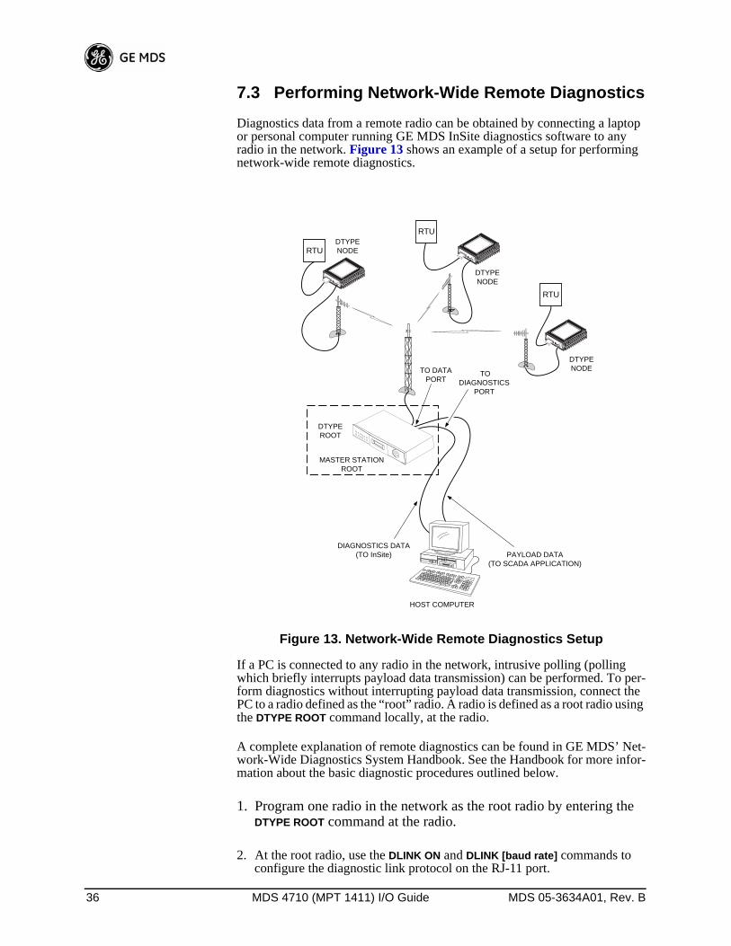
Diagnostics data from a remote radio can be obtained by connecting a laptop or personal computer running GE MDS InSite diagnostics software to any radio in the network. Figure 13 shows an example of a setup for performing network-wide remote diagnostics.
Invisible place holder
Figure 13. Network-Wide Remote Diagnostics Setup
If a PC is connected to any radio in the network, intrusive polling (polling which briefly interrupts payload data transmission) can be performed. To per-form diagnostics without interrupting payload data transmission, connect the PC to a radio defined as the “root” radio. A radio is defined as a root radio using the DTYPE ROOT command locally, at the radio.
A complete explanation of remote diagnostics can be found in GE MDS’ Net-work-Wide Diagnostics System Handbook. See the Handbook for more infor-mation about the basic diagnostic procedures outlined below.
1. Program one radio in the network as the root radio by entering the DTYPE ROOT command at the radio.
2. At the root radio, use the DLINK ON and DLINK [baud rate] commands to configure the diagnostic link protocol on the RJ-11 port.
RTU
DIAGNOSTICS DATA(TO InSite)
HOST COMPUTER
RTU
TODIAGNOSTICS
PORT
TO DATAPORT
MASTER STATIONROOT
DTYPEROOT
PAYLOAD DATA(TO SCADA APPLICATION)
RTU
DTYPENODE
DTYPENODE
DTYPENODE

MDS 05-3634A01, Rev. B MDS 4710 (MPT 1411) I/O Guide 37
3. Program all other radios in the network as nodes by entering the DTYPE NODE command at each radio.
4. Use the DLINK ON and DLINK [baud rate] commands to configure the diag-nostic link protocol on the RJ-11 port of each node radio.
5. Connect same-site radios using a null-modem cable at the radios’ diag-nostic ports.
6. Connect a PC on which GE MDS InSite software is installed to the root radio, or to one of the nodes, at the radio’s diagnostic port. (This PC may be the PC being used to collect payload data, as shown in Figure 13.)
To connect a PC to the radio’s DIAG. port, an RJ-11 to DB-9 adapter (GE MDS P/N 03-3246A01) is required. If desired, an adapter cable may be constructed from scratch using the information shown in Figure 14.
Invisible place holder
Figure 14. RJ-11 to DB-9 Adapter Cable
7. Launch the GE MDS InSite application at the PC. (See the GE MDS InSite User’s Guide for instructions.)
7.4 Upgrading the Radio’s SoftwareWindows-based Radio Configuration software is available (GE MDS P/N 03-3156A01) for upgrading the internal radio software when new features become available from GE MDS. Contact GE MDS for ordering information.
To connect a PC to the radio’s DIAG. port, an RJ-11 to DB-9 adapter (GE MDS P/N 03-3246A01) is required. If desired, an adapter cable may be constructed from scratch using the information shown in Figure 14.
Using the Radio Configuration software, select RADIO SOFTWARE UPGRADE under the SYSTEM menu. Follow the prompts and online instructions to deter-mine how to proceed.
Software upgrades are distributed as ASCII files with a “.S28” extension. These files use the Motorola S-record format. When the download is activated, the radio’s PWR LED will flash rapidly, confirming that a download is in pro-cess. The download takes about two minutes.
NOTE: If a download fails, the radio is left unprogrammed and inoperative.This is indicated by the PWR LED flashing slowly (1 second on/1second off). This condition is only likely if there were to be a powerfailure to the computer or radio during the downloading process. Thedownload can be attempted again when the fault has been corrected.
RXD
TXD
GND
2
3
5
DB-9 FEMALE(TO COMPUTER)
TXD
RXD
GND
4
5
6
RJ-11 PLUG(TO RADIO)
RJ-11 PIN LAYOUT
16

38 MDS 4710 (MPT 1411) I/O Guide MDS 05-3634A01, Rev. B
7.5 dBm-Watts-Volts Conversion ChartTable 10 is provided as a convenience for determining the equivalent wattage or voltage of an RF power expressed in dBm.
Table 10. dBm-Watts-Volts Conversion—for 50 Ohm Systems
dBm V Po+53 100.0 200W+50 70.7 100W+49 64.0 80W+48 58.0 64W+47 50.0 50W+46 44.5 40W+45 40.0 32W+44 32.5 25W+43 32.0 20W+42 28.0 16W+41 26.2 12.5W+40 22.5 10W+39 20.0 8W+38 18.0 6.4W+37 16.0 5W+36 14.1 4W+35 12.5 3.2W+34 11.5 2.5W+33 10.0 2W+32 9.0 1.6W+31 8.0 1.25W+30 7.10 1.0W+29 6.40 800mW+28 5.80 640mW+27 5.00 500mW+26 4.45 400mW+25 4.00 320mW+24 3.55 250mW+23 3.20 200mW+22 2.80 160mW+21 2.52 125mW+20 2.25 100mW+19 2.00 80mW+18 1.80 64mW+17 1.60 50mW+16 1.41 40mW+15 1.25 32mW+14 1.15 25mW+13 1.00 20mW+12 .90 16mW+11 .80 12.5mW+10 .71 10mW+9 .64 8mW+8 .58 6.4mW+7 .500 5mW+6 .445 4mW+5 .400 3.2mW+4 .355 2.5mW+3 .320 2.0mW+2 .280 1.6mW+1 .252 1.25mW
dBm V Po0 .225 1.0mW-1 .200 .80mW-2 .180 .64mW-3 .160 .50mW-4 .141 .40mW-5 .125 .32mW-6 .115 .25mW-7 .100 .20mW-8 .090 .16mW-9 .080 .125mW-10 .071 .10mW-11 .064-12 .058-13 .050-14 .045-15 .040-16 .0355
dBm mV Po-17 31.5-18 28.5-19 25.1-20 22.5 .01mW-21 20.0-22 17.9-23 15.9-24 14.1-25 12.8-26 11.5-27 10.0-28 8.9-29 8.0-30 7.1 .001mW-31 6.25-32 5.8-33 5.0-34 4.5-35 4.0-36 3.5-37 3.2-38 2.85-39 2.5-40 2.25 .1µW-41 2.0-42 1.8-43 1.6-44 1.4-45 1.25-46 1.18-47 1.00-48 0.90
dBm mV Po-49 0.80-50 0.71 .01µW-51 0.64-52 0.57-53 0.50-54 0.45-55 0.40-56 0.351-57 0.32-58 0.286-59 0.251-60 0.225 .001µW-61 0.200-62 0.180-63 0.160-64 0.141
dBm µV Po-65 128-66 115-67 100-68 90-69 80-70 71 .1nW-71 65-72 58-73 50-74 45-75 40-76 35-77 32-78 29-79 25-80 22.5 .01nW-81 20.0-82 18.0-83 16.0-84 11.1-85 12.9-86 11.5-87 10.0-88 9.0-89 8.0-90 7.1 .001nW-91 6.1-92 5.75-93 5.0-94 4.5-95 4.0-96 3.51-97 3.2
dBm µV Po-98 2.9-99 2.51-100 2.25 .1pW-101 2.0-102 1.8-103 1.6-104 1.41-105 1.27-106 1.18
dBm nV Po-107 1000-108 900-109 800-110 710 .01pW-111 640-112 580-113 500-114 450-115 400-116 355-117 325-118 285-119 251-120 225 .001pW-121 200-122 180-123 160-124 141-125 128-126 117-127 100-128 90-129 80 .1ƒW-130 71-131 61-132 58-133 50-134 45-135 40-136 35-137 33-138 29-139 25-140 23 .01ƒW
MDS 05-3634A01, Rev. B MDS 4710 (MPT 1411) I/O Guide I-1
AACCESS DENIED error message 20Accessories 4Accessory Power pinout (Pin 18) 15Active messaging (defined) 5Alarms
alarm code definitions 31major vs. minor 31pinout (Pin 25) 16using STAT command to display 29
AMASK command 22Antenna
installation 8RSSI command used to refine heading 16system gain, defined 5Yagi, illustrated 13
Antennas 12–13Applications 2
Multiple Address Systems (MAS) 2point-to-multipoint system 2point-to-point system 2
ASENSE command 23
BBAUD command 23Baud rate
setting for RJ-11 DIAG port (DLINK command) 25, 36Bit, defined 5Bits-per-second. See BPS 5BPS (bits-per-second), defined 5BUFF command 24Byte, defined 5
CCable, loss due to length of coaxial at 400 MHz 13Cautions
use attenuation between all units in test setup 36CKEY command 24COMMAND FAILED error message 20Command summary, table 20Commands
AMASK (set/display alarm triggers) 22ASENSE (set alarm output state) 23BAUD (set/display rate, encoding) 23BUFF (set/display data handling mode) 24CKEY (enable/disable continuous keying) 24CTS (set/display CTS line response timer) 24DATAKEY (enable/disable transmitter keying by radio) 25descriptions 22–30DEVICE (set/display radio behavior) 25DKEY (deactivate transmitter after KEY command) 25DLINK (enable/disable network-wide diagnostics) 25DMGAP (set time to wait between characters) 25DTYPE (set radio to root or node for diagnostics) 26DUMP (display all programmed settings) 26entering on Hand-Held Terminal (HHT) 19Hand-Held Terminal (HHT) 19HREV (display hardware revision level) 26INIT (reinitialize radio to factory defaults) 26INIT xx10 (restore standard transceiver defaults) 26INIT xx20 (configure radio for use with P-20 chassis) 26KEY (activate transmitter) 27MODEL (display radio model number code) 27
MODEM (set modem speed) 27OWM (set/display owner’s message) 27OWN (set/display owner’s name) 27PTT (set/display key-up delay) 27PWR (set/display RF forward output power) 27RSSI (display RSSI) 28RTU (enable/disable internal RTU) 28RX (set/display receive frequency) 28RXTOT (set/display receive time-out timer value) 28SCD (set/display soft-carrier dekey delay) 28SER (display radio serial number 28SHOW (display DC voltage, data port, RF power) 29SNR (display signal-to-noise ratio) 29SREV (display software revision level) 29STAT (display current alarm status) 29TEMP (display internal temperature) 29TOT (set/display time-out value and timer status) 29TX (set/display transmit frequency) 30
Conversions, dBm-Watts-Volts 38CTS command 24CTS pinout (Pin 5) 14
DData interface
connector pinouts 14display active connector port 29installing connection 13
DATAKEY command 25dB. See Decibel 5dBi, defined 5dBm, defined 5DCD
LED 17pinout (Pin 8) 15
DCE (Data Cirtuit-terminating Equipment), defined 5Decibel (dB), defined 5Description, product 1DEVICE command 25Diagnostic Channel Enable, pinout (Pin 23) 16Diagnostics
interface specifications 35network-wide, performing 36PC software used for 37using InSite software for network-wide 36
Displayalarm status (STAT command) 29alarm triggers (AMASK command) 22all programmed settings (DUMP command) 26baud rate and encoding (BAUD command) 23connector port, active (SHOW command) 29CTS line response timer (CTS command) 24data handling mode (BUFF command) 24DC voltage (SHOW command) 29hardware revision leve (HREV command)l 26key-up delay (PTT command) 27model number code (MODEL command) 27owner’s message (OWM command) 27owner’s name (OWN command) 27radio behavior (DEVICE command) 25radio serial number (SER command) 28receive frequency (RX command) 28receive time-out timer value (RXTOT command) 28RF forward output power (PWR command) 27RF output (SHOW command) 29RSSI (RSSI command) 28

I-2 MDS 4710 (MPT 1411) I/O Guide MDS 05-3634A01, Rev. B
signal-to-noise ratio (SNR command) 29soft-carrier dekey delay (SCD command) 28software revision level (SREV command) 29temperature, internal (TEMP command) 29time-out value and timer status (TOT command) 29transmit frequency (TX command) 30
DKEY command 25DLINK command 25
use of 36DMGAP command 25Downloading new software 37DSP (Digital Signal Processing), defined 5DSR pinout (Pin 6) 14DTE (Data Terminal Equipment), defined 5DTYPE command 26
use of 36DUMP command 26
EEEPROM FAILURE error message 20Enable/disable
continuous keying (CKEY command) 24diagnostic channel, pinout (Pin 23) 16internal RTU (RTU command) 28network-wide diagnostics (DLINK command) 25network-wide diagnostics, procedures 36
Environment specifications 34Equalization, defined 5Error messages 20
access denied 20command failed 20EEPROM failure 20incorrect entry 20not available 20not programmed 20text too long 20unknown command 20
FFade margin, defined 6Feedlines 13Filter, helical, adjustment 35Frame, defined 6Frequency
adjusting helical filter when changed 35setting. See TX and RX commands
GGlossary 5Ground
on Pin 12 to enable Sleep mode 15protective (Pin 1) 14signal (Pin 7) 15
HHalf-duplex 2
switched carrier operation 3Hand-Held Terminal (HHT) 4
connected to transceiver, illustrated 18connection and startup 18display in response to STAT command, illustrated 31
entering commands 19error messages displayed on 20keyboard commands 19operational settings, table 19reinitialization display, illustrated 19reinitializing 18
Hardware flow control, defined 6Helical filter
adjusting 35illustration 35
Host computer, defined 6HREV command 26
IIllustrations
4710A model number codes 4antenna, Yagi 13Hand-Held Terminal (HHT) connected to transceiver 18Hand-Held Terminal (HHT) reinitialization display 19Hand-Held Terminal display in response to STAT
command 31helical filter locations 35MAS network 2network-wide diagnostics 36point-to-point link 3remote station arrangement 8RJ-11 to DB-9 adapter cable 37RSSI vs. Vdc 14, 17transceiver connectors & indicators 1transceiver mounting dimensions 12
INCORRECT ENTRY error message 20INIT command 26INIT xx10 command 26INIT xx20 command 26InSite software
using to perform remote diagnostics 36Installation 7–16
antenna 8configuring transceiver 9DATA INTERFACE connection 8data interface connections 13power 8power connection 13steps 8
Intrusive diagnostics (defined) 6
KKEY command 27Keying
continuously keyed versus switched carrier operation 3continuously keyed, defined 3on data (DKEY command) 25switched carrier, defined 3
LLatency, defined 6LEDs
DCD 17indicators, described 16PWR 17RXD 17RXD, Pin 3 14

MDS 05-3634A01, Rev. B MDS 4710 (MPT 1411) I/O Guide I-3
status indicators, illustrated 17TXD 17TXD, Pin 2 14
Loss. See Signal
MMAS (Multiple Address System) 2
defined 6illustration 2
Master Stationdefined 6keying behavior 3
MCU (Microcontroller Unit), defined 6MODEL command 27Model number codes 3
4710A, illustrated 4displaying (MODEL command) 27
MODEM command 27Modem, set speed. See MODEM command
NNetwork-wide diagnostics
active messaging, defined 5defined 6enable/disable (DLINK command) 25enable/disable internal RTU (RTU command) 28illustrated 36intrusive diagnostics, defined 6passive messaging (defined) 6procedures 36set radio to root or node (DTYPE command) 26set time to wait between characters (DMGAP
command) 25NOT AVAILABLE error message 20NOT PROGRAMMED error message 20
OOperation 16–??
environment specifications for 34Output, 9.9 Vdc regulated, pinout (Pin 19) 15OWM command 27OWN command 27Owner’s message, set/display. See OWM commandOwner’s name, set/display. See OWN command
PPassive messaging (defined) 6Payload data (defined) 6Pinouts on data interface 14PLC (Programmable Logic Controller), defined 7Point-to-multipoint
defined 7system 2
Point-to-pointlink, illustrated 3system 2
Poll, defined 7Power
connection 13display DC voltage (SHOW command) 29display RF output (SHOW command) 29
installing 8LED status indicator (PWR LED) 17RF, chart for converting dBm-Watts-Volts 38specifications 34
Procedureschecking for alarms (STAT command) 30connecting Hand-Held Terminal (HHT) 18downloading new software 37entering commands using the Hand-Held Terminal
(HHT) 19helical filter adjustment 35installation 8measuring RSSI with DC voltmeter 17network-wide diagnostics 36operation 16performance optimization 16reading LED status indicators 16resetting Hand-Held Terminal (HHT) 18troubleshooting 30–32
Productaccessories 4description 1display model number code (MODEL command) 27display radio serial number (SER command) 28model number codes 3
Programming radio as root or node 36Programming, transceiver 17–30PTT
command 27pinout (Pins 14, 16) 15
PWRcommand 27LED 17
RRadio
Configuration Software 4, 37Inhibit pinout (Pin 12) 15serial number, displaying (SER command) 28
Receive Audio Output pinout (Pin 11) 15Receiver
specifications 34system specifications 33unsquelched signal (Pin 10) 15
Redundant operation, defined 7Remote
RTU reset (Pin 15) 15Station, defined 7Station, illustrated 8
ResettingHand-Held Terminal (HHT) (SHIFT,CTRL,SPACE
keys) 18remote RTU reset (Pin 15) 15transceiver (INIT command) 26
Revision leveldisplay hardware (HREV command) 26display software (SREV command) 29
RSSIadjusting helical filter for increased signal strength 35command 28command, used to refine antenna heading 16measuring 17pinout (Pin 21) 16vs. Vdc, illustrated 14, 17
RTS pinout (Pin 4) 14

I-4 MDS 4710 (MPT 1411) I/O Guide MDS 05-3634A01, Rev. B
RTUcommand 28
RTU (Remote Terminal Unit)defined 7remote reset (Pin 15) 15
RUS pinout (Pin10) 15RX command 28RXD LED
description 17Pin 3 14
RXTOT command 28
SSCADA (Supervisory Control And Data Acquisition),
defined 7SCD command 28SER command 28Set
alarm output state (ASENSE command) 23alarm triggers (AMASK command) 22receive time-out timer value (RXTOT command) 28
SHOW command 29Signal
ground (Pin 7) 15loss due to coaxial cable length, table 13
Simplex 2single-frequency operation 3special case of switched carrier operation 3
Sleep modeexample implementation 14ground on Radio Inhibit pin activates 15Pin 12 15shown by PWR LED status indicator 17
SNR command 29Software
diagnostics and control used from PC 37display revision level 29upgrades (.S28 files) 37upgrading 37used for diagnostics and programming 17
Specificationsdiagnostics interface 35environment 34power 34receiver 34receiver system 33transceiver 32–35transmitter 33transmitter system 32
SREV command 29STAT command 29SWR (Standing Wave Radio), defined 7
TTables
accessories 4alarm code definitions 31command summary 20conversions, dBm-Watts-Volts 38data interface connector pinouts 14Hand-Held Terminal (HHT) operational settings 19LED status indicators 17length vs. loss in coaxial cables 13
Technical reference 32–38
TEMP command 29Temperature, displaying internal (TEMP command) 29TEXT TOO LONG error message 20Timer, set/display time-out value and status (TOT
command) 29TOT command 29Transceiver
applications 2configuring for operation 9connectors and indicators, illustrated 1diagnostics using PC software 37dimensions, mounting 12mounting 8, 12programming 17–30specifications 32–35upgrading software 37
Transmit Audio Input pinout (Pin 9) 15Transmitter
specifications 33system specifications 32
Troubleshooting 30–32connecting Hand-Held Terminal (HHT) for displaying
alarm codes 18performing network-wide diagnostics 36STAT command (Status) 30using PC software for 37
TX command 30TXD LED
description 17Pin 2 14
UUNKNOWN COMMAND error message 20

IN CASE OF DIFFICULTY...GE MDS products are designed for long life and trouble-free operation. However, this equipment, as with all electronic equipment, may have an occasional component failure. The following infor-mation will assist you in the event that servicing becomes necessary.
FACTORY TECHNICAL ASSISTANCE
Technical assistance for GE MDS products is available from our Customer Support Team during business hours (8:00 A.M.–5:30 P.M. Eastern Time). When calling, please give the complete model number of the radio, along with a description of the trouble symptom(s) that you are expe-riencing. In many cases, problems can be resolved over the telephone, without the need for returning the unit to the factory.
Please use the following telephone numbers for product assistance:
585-242-9600 (Phone)585-242-9620 (FAX)
FACTORY REPAIRS
Component level repair of radio equipment is not recommended in the field. Many components are installed using surface mount technology, which requires specialized training and equipment for proper servicing. For this reason, the equipment should be returned to the factory for any PC board repairs. The factory is best equipped to diagnose, repair and align your radio to its proper operating specifications.
If return of the equipment is necessary, you will be issued a Returned Material Authorization (RMA) number. The RMA number will help expedite the repair so that the equipment can be repaired and returned to you as quickly as possible. Please be sure to include the RMA number on the outside of the shipping box, and on any correspondence relating to the repair. No equipment will be accepted for repair without an RMA number.
A statement should accompany the radio describing, in detail, the trouble symptom(s), and a description of any associated equipment normally connected to the radio. It is also important to include the name and telephone number of a person in your organization who can be contacted if additional information is required.
The radio must be properly packed for return to the factory. The original shipping container and packaging materials should be used whenever possible. All factory returns should be addressed to:
When repairs have been completed, the equipment will be returned to you by the same shipping method used to send it to the factory. Please specify if you wish to make different shipping arrangements.
GE MDSCustomer Service Department(RMA No. XXXX)175 Science ParkwayRochester, NY 14620 USA

GE MDS, LLC175 Science ParkwayRochester, NY 14620
General Business: +1 585 242-9600FAX: +1 585 242-9620Web: www.GEmds.com