36 Service Manual - Packard Bell -Easynote m5 m7 Versa m400
31
www.SoporteTecnicoBsAs.com.ar Repuestos para tus equipos. Al mejor precio. Envios a Todo el Pais
-
Upload
soporte-tecnico-buenos-aires -
Category
Documents
-
view
225 -
download
0
Transcript of 36 Service Manual - Packard Bell -Easynote m5 m7 Versa m400
8/8/2019 36 Service Manual - Packard Bell -Easynote m5 m7 Versa m400
http://slidepdf.com/reader/full/36-service-manual-packard-bell-easynote-m5-m7-versa-m400 1/31
8/8/2019 36 Service Manual - Packard Bell -Easynote m5 m7 Versa m400
http://slidepdf.com/reader/full/36-service-manual-packard-bell-easynote-m5-m7-versa-m400 2/31
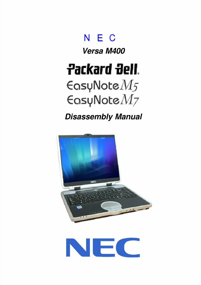
Versa M400
Disassembly Manual
8/8/2019 36 Service Manual - Packard Bell -Easynote m5 m7 Versa m400
http://slidepdf.com/reader/full/36-service-manual-packard-bell-easynote-m5-m7-versa-m400 3/31
8/8/2019 36 Service Manual - Packard Bell -Easynote m5 m7 Versa m400
http://slidepdf.com/reader/full/36-service-manual-packard-bell-easynote-m5-m7-versa-m400 4/31
NEC Versa M400/PB EasyNoteM5 M7 Disassembly Manual
Page 3
OverviewThis document contains step-by-steps disassembly instructions for the Versa M400/PB EasyNoteM5 M7 chassis.The instructions are illustrated where necessary with images of the part that is being removed or disassembled.
Furthermore, the screws that are removed are shown next to the image of the parts themselves. NEC reserves the right to make changes to the Versa M400 chassis without notice.
Technician NotesOnly technicians authorized by NEC Computers International BV should attempt to repair this equipment. Alltroubleshooting and repair procedures are detailed to allow only subassembly/module level repair. Because of thecomplexity of the individual boards and subassemblies, no one should attempt to make repairs at the componentlevel or to make modifications to any printed wiring board. Improper repairs can create a safety hazard. Anyindication of component replacement or printed wiring board modifications may void any warranty or exchangeallowances.
Disassembly Instructions
When disassembling the system unit, follow these general rules:
Do not disassemble the system into parts that are smaller than those specified in the instructions. Label all removed connectors. Note where the connector goes and in what position it was installed. Turn off the power and disconnect all power and all options.
Reassembly InstructionsReassembly is the reverse of the disassembly process. Use care to ensure that all cables and screws are returnedto their proper positions. Check that no tools or any loose parts have been left inside the chassis. Check thateverything are properly installed and tightened.
Required Tools
All disassembly procedures can be perform using the following tools:
PH 0x60 Philips screwdriver PH 0x40 Philips screwdriver
4.0 x 60 Flat screwdriver 2.0 x 30 Flat screwdriver SW5.0 Spacer screwdriver Small tweezers Pin
8/8/2019 36 Service Manual - Packard Bell -Easynote m5 m7 Versa m400
http://slidepdf.com/reader/full/36-service-manual-packard-bell-easynote-m5-m7-versa-m400 5/31
8/8/2019 36 Service Manual - Packard Bell -Easynote m5 m7 Versa m400
http://slidepdf.com/reader/full/36-service-manual-packard-bell-easynote-m5-m7-versa-m400 6/31
NEC Versa M400/PB EasyNoteM5 M7 Disassembly Manual
Page 5
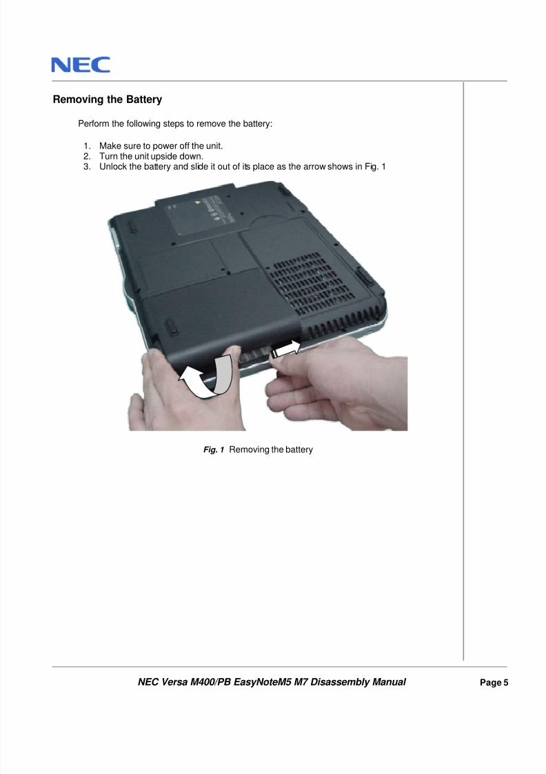
Removing the Battery
Perform the following steps to remove the battery:
1. Make sure to power off the unit.2. Turn the unit upside down.3. Unlock the battery and slide it out of its place as the arrow shows in Fig. 1
Fig. 1 Removing the battery
8/8/2019 36 Service Manual - Packard Bell -Easynote m5 m7 Versa m400
http://slidepdf.com/reader/full/36-service-manual-packard-bell-easynote-m5-m7-versa-m400 7/31
NEC Versa M400/PB EasyNoteM5 M7 Disassembly Manual
Page 6
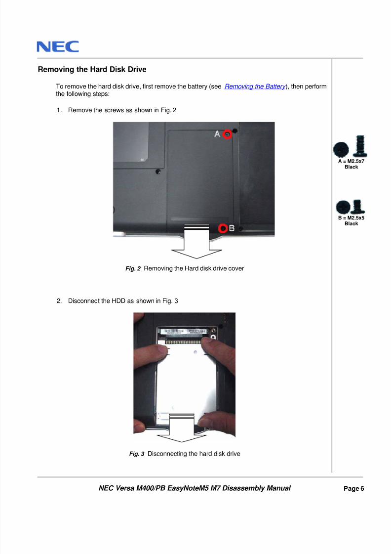
Removing the Hard Disk Drive
To remove the hard disk drive, first remove the battery (see Removing the Battery ), then perform
the following steps:
1. Remove the screws as shown in Fig. 2
Fig. 2 Removing the Hard disk drive cover
2. Disconnect the HDD as shown in Fig. 3
Fig. 3 Disconnecting the hard disk drive
A = M2.5x7Black
B = M2.5x5
Black
8/8/2019 36 Service Manual - Packard Bell -Easynote m5 m7 Versa m400
http://slidepdf.com/reader/full/36-service-manual-packard-bell-easynote-m5-m7-versa-m400 8/31
NEC Versa M400/PB EasyNoteM5 M7 Disassembly Manual
Page 7
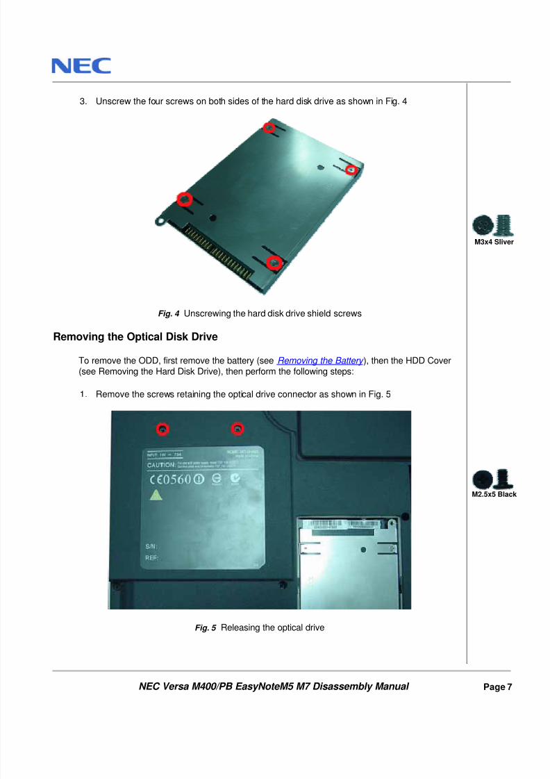
3. Unscrew the four screws on both sides of the hard disk drive as shown in Fig. 4
Fig. 4 Unscrewing the hard disk drive shield screws
Removing the Optical Disk Drive
To remove the ODD, first remove the battery (see Removing the Battery ), then the HDD Cover(see Removing the Hard Disk Drive), then perform the following steps:
1. Remove the screws retaining the optical drive connector as shown in Fig. 5
Fig. 5 Releasing the optical drive
M3x4 Sliver
M2.5x5 Black
8/8/2019 36 Service Manual - Packard Bell -Easynote m5 m7 Versa m400
http://slidepdf.com/reader/full/36-service-manual-packard-bell-easynote-m5-m7-versa-m400 9/31
NEC Versa M400/PB EasyNoteM5 M7 Disassembly Manual
Page 8
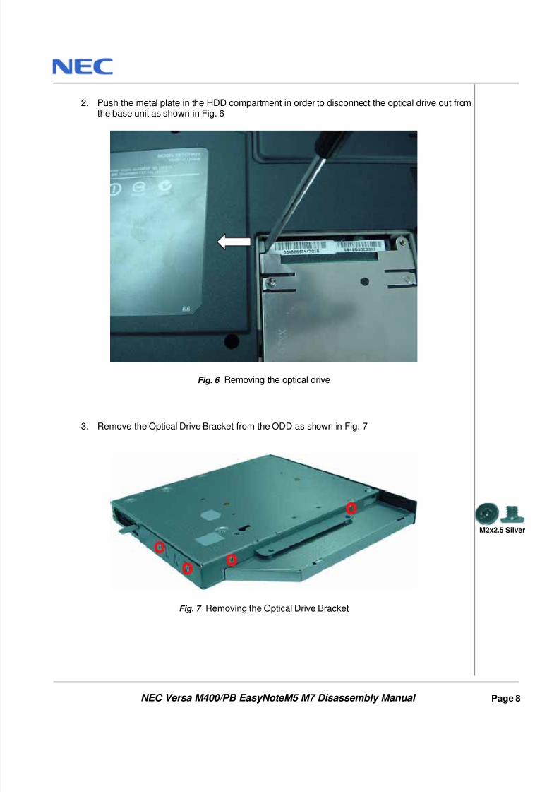
2. Push the metal plate in the HDD compartment in order to disconnect the optical drive out fromthe base unit as shown in Fig. 6
Fig. 6 Removing the optical drive
3. Remove the Optical Drive Bracket from the ODD as shown in Fig. 7
Fig. 7 Removing the Optical Drive Bracket
M2x2.5 Silver
8/8/2019 36 Service Manual - Packard Bell -Easynote m5 m7 Versa m400
http://slidepdf.com/reader/full/36-service-manual-packard-bell-easynote-m5-m7-versa-m400 10/31
NEC Versa M400/PB EasyNoteM5 M7 Disassembly Manual
Page 9
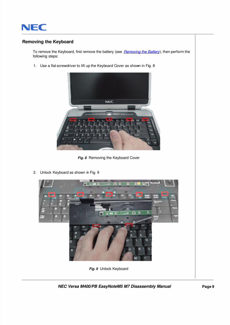
Removing the Keyboard
To remove the Keyboard, first remove the battery (see Removing the Battery ), then perform the
following steps:
1. Use a flat screwdriver to lift up the Keyboard Cover as shown in Fig. 8
Fig. 8 Removing the Keyboard Cover
2. Unlock Keyboard as shown in Fig. 9
Fig. 9 Unlock Keyboard
8/8/2019 36 Service Manual - Packard Bell -Easynote m5 m7 Versa m400
http://slidepdf.com/reader/full/36-service-manual-packard-bell-easynote-m5-m7-versa-m400 11/31
NEC Versa M400/PB EasyNoteM5 M7 Disassembly Manual
Page 10
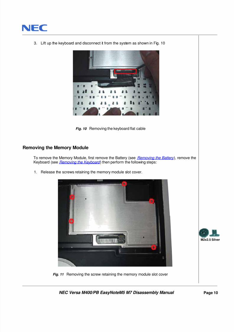
3. Lift up the keyboard and disconnect it from the system as shown in Fig. 10
Fig. 10 Removing the keyboard flat cable
Removing the Memory Module
To remove the Memory Module, first remove the Battery (see Removing the Battery ), remove theKeyboard (see Removing the Keyboard ) then perform the following steps:
1. Release the screws retaining the memory module slot cover.
Fig. 11 Removing the screw retaining the memory module slot cover
M2x2.5 Silver
8/8/2019 36 Service Manual - Packard Bell -Easynote m5 m7 Versa m400
http://slidepdf.com/reader/full/36-service-manual-packard-bell-easynote-m5-m7-versa-m400 12/31
NEC Versa M400/PB EasyNoteM5 M7 Disassembly Manual
Page 11
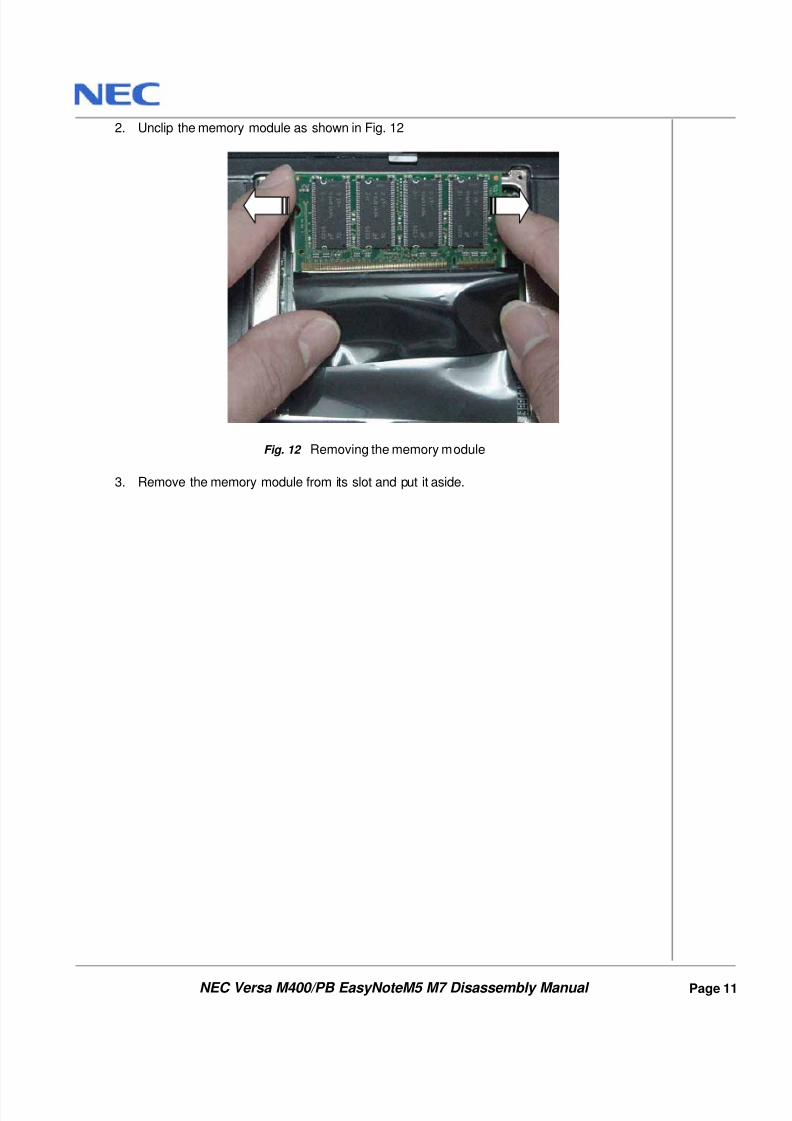
2. Unclip the memory module as shown in Fig. 12
Fig. 12 Removing the memory module
3. Remove the memory module from its slot and put it aside.
8/8/2019 36 Service Manual - Packard Bell -Easynote m5 m7 Versa m400
http://slidepdf.com/reader/full/36-service-manual-packard-bell-easynote-m5-m7-versa-m400 13/31
NEC Versa M400/PB EasyNoteM5 M7 Disassembly Manual
Page 12
Removing the LCD Module
To remove the LCD Module, first remove the Battery (see Removing the Battery ), remove the
Keyboard (see Removing the Keyboard ) then perform the following steps:
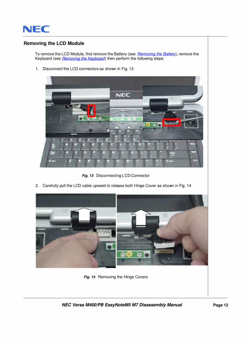
1. Disconnect the LCD connectors as shown in Fig. 13
Fig. 13 Disconnecting LCD Connector
2. Carefully pull the LCD cable upward to release both Hinge Cover as shown in Fig. 14
Fig. 14 Removing the Hinge Covers
8/8/2019 36 Service Manual - Packard Bell -Easynote m5 m7 Versa m400
http://slidepdf.com/reader/full/36-service-manual-packard-bell-easynote-m5-m7-versa-m400 14/31
NEC Versa M400/PB EasyNoteM5 M7 Disassembly Manual
Page 13
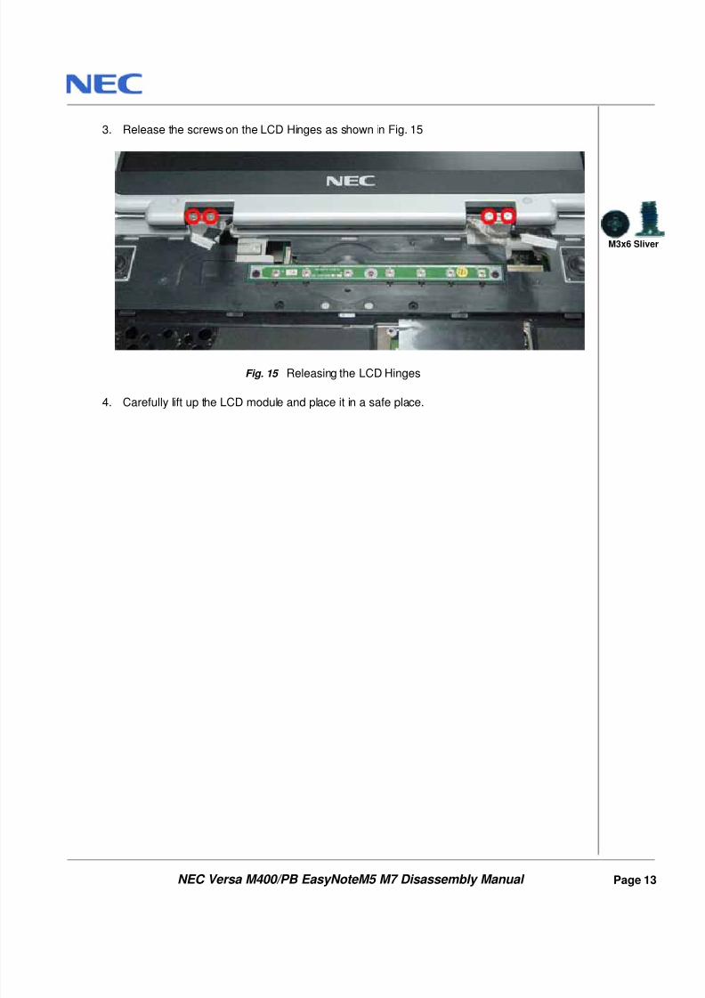
3. Release the screws on the LCD Hinges as shown in Fig. 15
Fig. 15 Releasing the LCD Hinges
4. Carefully lift up the LCD module and place it in a safe place.
M3x6 Sliver
8/8/2019 36 Service Manual - Packard Bell -Easynote m5 m7 Versa m400
http://slidepdf.com/reader/full/36-service-manual-packard-bell-easynote-m5-m7-versa-m400 15/31
NEC Versa M400/PB EasyNoteM5 M7 Disassembly Manual
Page 14
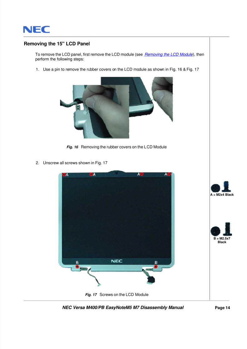
Removing the 15" LCD Panel
To remove the LCD panel, first remove the LCD module (see Removing the LCD Module ), then
perform the following steps:
1. Use a pin to remove the rubber covers on the LCD module as shown in Fig. 16 & Fig. 17
Fig. 16 Removing the rubber covers on the LCD Module
2. Unscrew all screws shown in Fig. 17
Fig. 17 Screws on the LCD Module
A = M2x4 Black
B = M2.5x7Black
8/8/2019 36 Service Manual - Packard Bell -Easynote m5 m7 Versa m400
http://slidepdf.com/reader/full/36-service-manual-packard-bell-easynote-m5-m7-versa-m400 16/31
NEC Versa M400/PB EasyNoteM5 M7 Disassembly Manual
Page 15
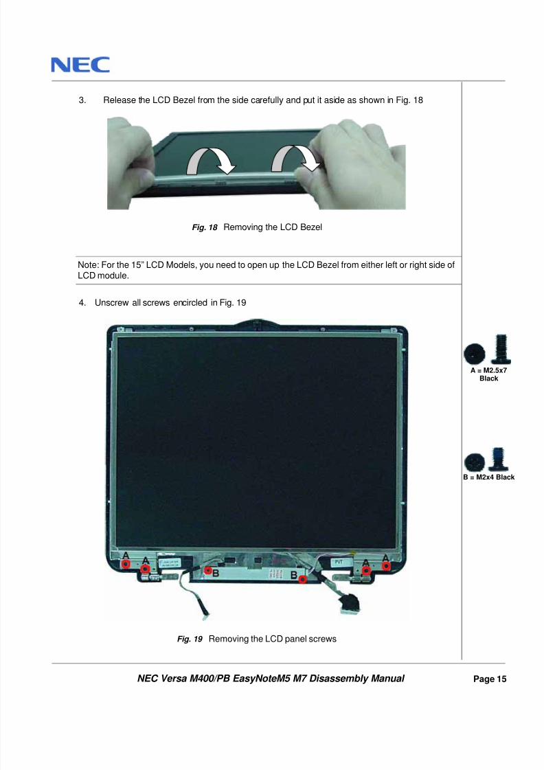
3. Release the LCD Bezel from the side carefully and put it aside as shown in Fig. 18
Fig. 18 Removing the LCD Bezel
Note: For the 15” LCD Models, you need to open up the LCD Bezel from either left or right side ofLCD module.
4. Unscrew all screws encircled in Fig. 19
Fig. 19 Removing the LCD panel screws
A = M2.5x7Black
B = M2x4 Black
8/8/2019 36 Service Manual - Packard Bell -Easynote m5 m7 Versa m400
http://slidepdf.com/reader/full/36-service-manual-packard-bell-easynote-m5-m7-versa-m400 17/31
NEC Versa M400/PB EasyNoteM5 M7 Disassembly Manual
Page 16
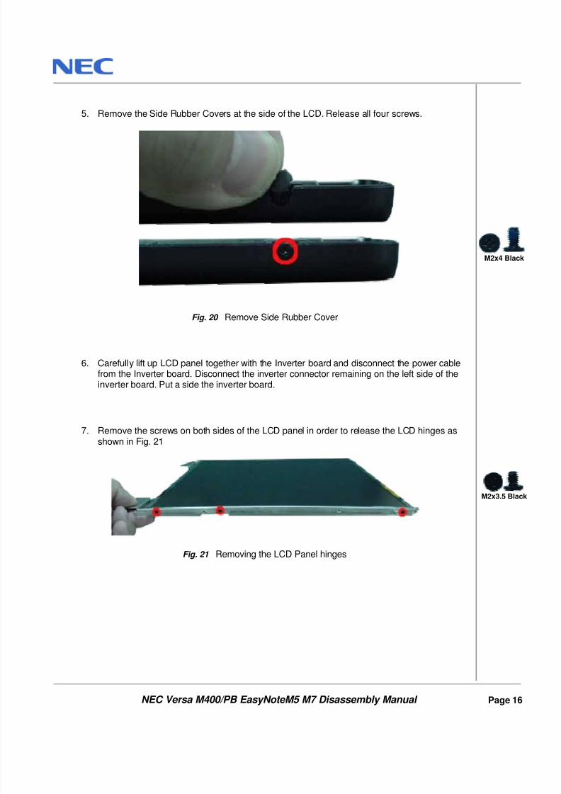
5. Remove the Side Rubber Covers at the side of the LCD. Release all four screws.
Fig. 20 Remove Side Rubber Cover
6. Carefully lift up LCD panel together with the Inverter board and disconnect the power cablefrom the Inverter board. Disconnect the inverter connector remaining on the left side of theinverter board. Put a side the inverter board.
7. Remove the screws on both sides of the LCD panel in order to release the LCD hinges asshown in Fig. 21
Fig. 21 Removing the LCD Panel hinges
M2x4 Black
M2x3.5 Black
8/8/2019 36 Service Manual - Packard Bell -Easynote m5 m7 Versa m400
http://slidepdf.com/reader/full/36-service-manual-packard-bell-easynote-m5-m7-versa-m400 18/31
NEC Versa M400/PB EasyNoteM5 M7 Disassembly Manual
Page 17
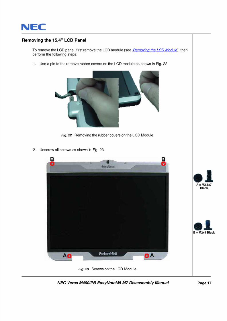
Removing the 15.4" LCD Panel
To remove the LCD panel, first remove the LCD module (see Removing the LCD Module ), then
perform the following steps:
1. Use a pin to the remove rubber covers on the LCD module as shown in Fig. 22
Fig. 22 Removing the rubber covers on the LCD Module
2. Unscrew all screws as shown in Fig. 23
Fig. 23 Screws on the LCD Module
A = M2.5x7Black
B = M2x4 Black
8/8/2019 36 Service Manual - Packard Bell -Easynote m5 m7 Versa m400
http://slidepdf.com/reader/full/36-service-manual-packard-bell-easynote-m5-m7-versa-m400 19/31
NEC Versa M400/PB EasyNoteM5 M7 Disassembly Manual
Page 18
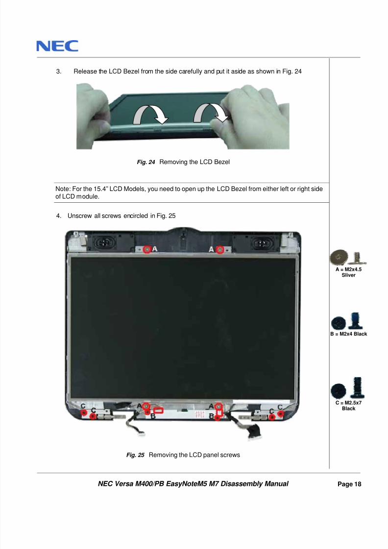
3. Release the LCD Bezel from the side carefully and put it aside as shown in Fig. 24
Fig. 24 Removing the LCD Bezel
Note: For the 15.4” LCD Models, you need to open up the LCD Bezel from either left or right sideof LCD module.
4. Unscrew all screws encircled in Fig. 25
Fig. 25 Removing the LCD panel screws
A = M2x4.5Sliver
B = M2x4 Black
C = M2.5x7Black
8/8/2019 36 Service Manual - Packard Bell -Easynote m5 m7 Versa m400
http://slidepdf.com/reader/full/36-service-manual-packard-bell-easynote-m5-m7-versa-m400 20/31
NEC Versa M400/PB EasyNoteM5 M7 Disassembly Manual
Page 19
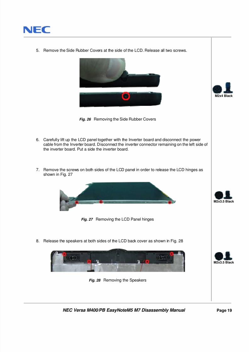
5. Remove the Side Rubber Covers at the side of the LCD. Release all two screws.
Fig. 26 Removing the Side Rubber Covers
6. Carefully lift up the LCD panel together with the Inverter board and disconnect the powercable from the Inverter board. Disconnect the inverter connector remaining on the left side ofthe inverter board. Put a side the inverter board.
7. Remove the screws on both sides of the LCD panel in order to release the LCD hinges asshown in Fig. 27
Fig. 27 Removing the LCD Panel hinges
8. Release the speakers at both sides of the LCD back cover as shown in Fig. 28
Fig. 28 Removing the Speakers
M2x4 Black
M2x3.5 Black
M2x3.5 Black
8/8/2019 36 Service Manual - Packard Bell -Easynote m5 m7 Versa m400
http://slidepdf.com/reader/full/36-service-manual-packard-bell-easynote-m5-m7-versa-m400 21/31
NEC Versa M400/PB EasyNoteM5 M7 Disassembly Manual
Page 20
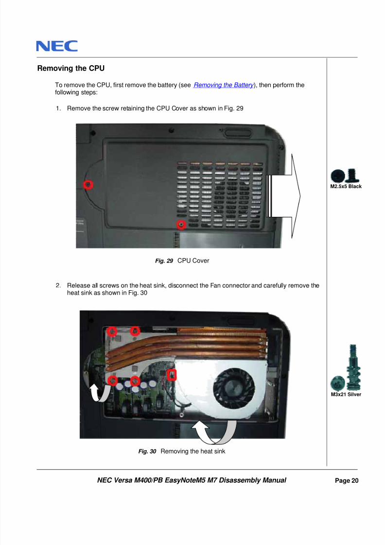
Removing the CPU
To remove the CPU, first remove the battery (see Removing the Battery ), then perform the
following steps:
1. Remove the screw retaining the CPU Cover as shown in Fig. 29
Fig. 29 CPU Cover
2. Release all screws on the heat sink, disconnect the Fan connector and carefully remove theheat sink as shown in Fig. 30
Fig. 30 Removing the heat sink
M2.5x5 Black
M3x21 Silver
8/8/2019 36 Service Manual - Packard Bell -Easynote m5 m7 Versa m400
http://slidepdf.com/reader/full/36-service-manual-packard-bell-easynote-m5-m7-versa-m400 22/31
NEC Versa M400/PB EasyNoteM5 M7 Disassembly Manual
Page 21
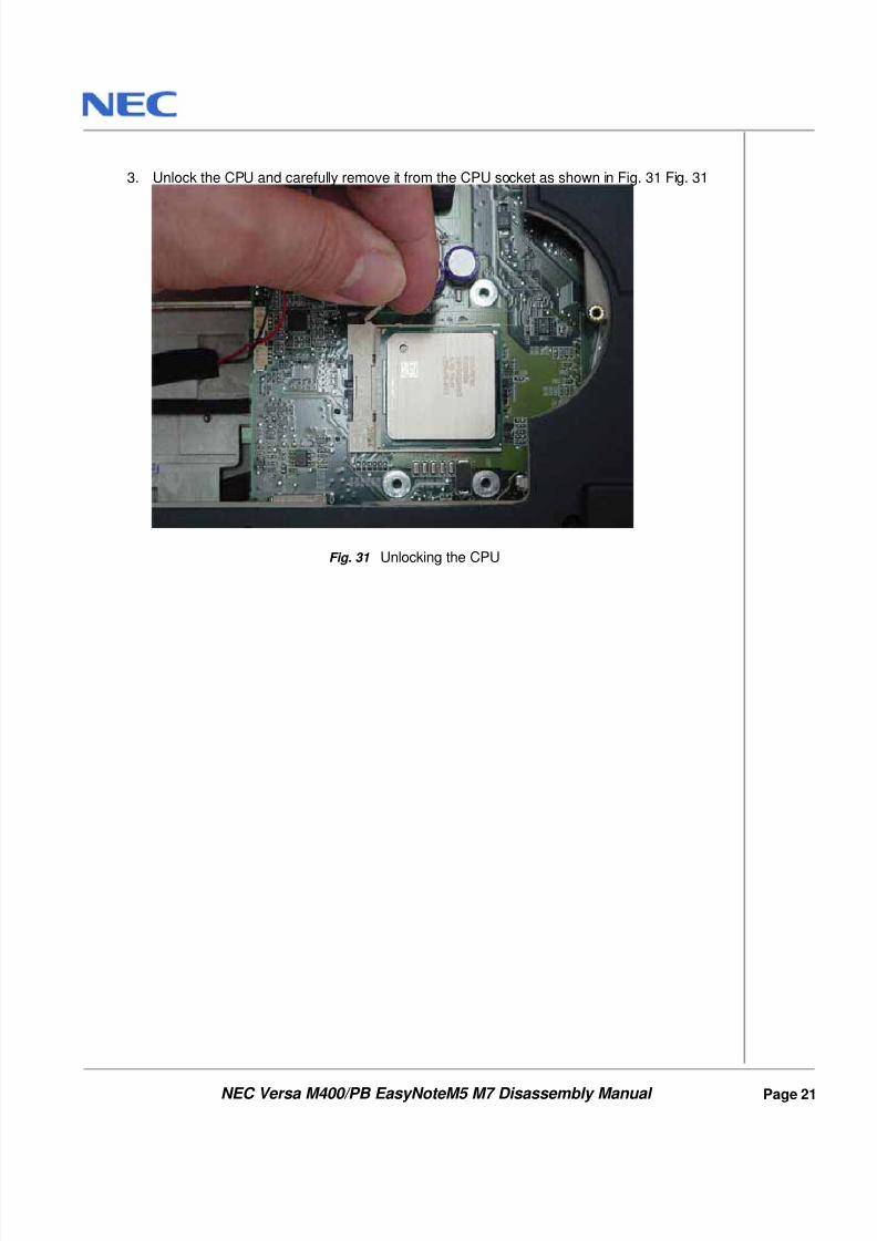
3. Unlock the CPU and carefully remove it from the CPU socket as shown in Fig. 31 Fig. 31
Fig. 31 Unlocking the CPU
8/8/2019 36 Service Manual - Packard Bell -Easynote m5 m7 Versa m400
http://slidepdf.com/reader/full/36-service-manual-packard-bell-easynote-m5-m7-versa-m400 23/31
NEC Versa M400/PB EasyNoteM5 M7 Disassembly Manual
Page 22
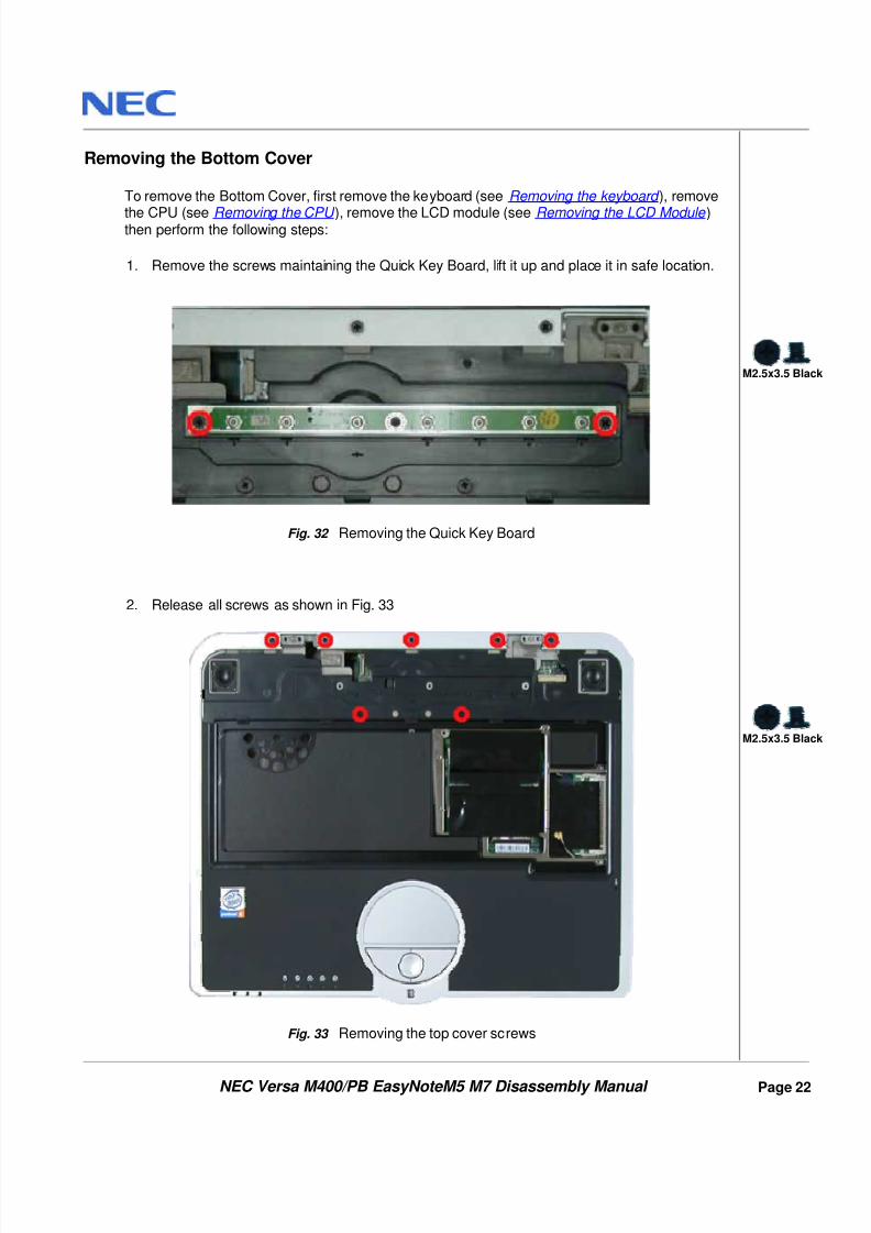
Removing the Bottom Cover
To remove the Bottom Cover, first remove the keyboard (see Removing the keyboard ), remove
the CPU (see Removing the CPU ), remove the LCD module (see Removing the LCD Module )then perform the following steps:
1. Remove the screws maintaining the Quick Key Board, lift it up and place it in safe location.
Fig. 32 Removing the Quick Key Board
2. Release all screws as shown in Fig. 33
Fig. 33 Removing the top cover screws
M2.5x3.5 Black
M2.5x3.5 Black
8/8/2019 36 Service Manual - Packard Bell -Easynote m5 m7 Versa m400
http://slidepdf.com/reader/full/36-service-manual-packard-bell-easynote-m5-m7-versa-m400 24/31
NEC Versa M400/PB EasyNoteM5 M7 Disassembly Manual
Page 23
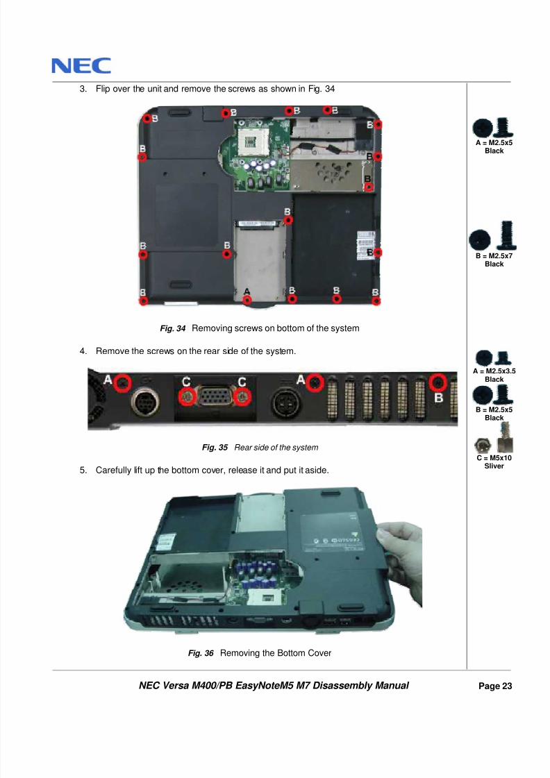
3. Flip over the unit and remove the screws as shown in Fig. 34
Fig. 34 Removing screws on bottom of the system
4. Remove the screws on the rear side of the system.
Fig. 35 Rear side of the system
5. Carefully lift up the bottom cover, release it and put it aside.
Fig. 36 Removing the Bottom Cover
A = M2.5x5
Black
B = M2.5x7Black
A = M2.5x3.5
Black
B = M2.5x5Black
C = M5x10
Sliver
8/8/2019 36 Service Manual - Packard Bell -Easynote m5 m7 Versa m400
http://slidepdf.com/reader/full/36-service-manual-packard-bell-easynote-m5-m7-versa-m400 25/31
NEC Versa M400/PB EasyNoteM5 M7 Disassembly Manual
Page 24
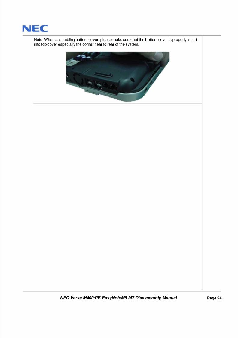
Note: When assembling bottom cover, please make sure that the bottom cover is properly insertinto top cover especially the corner near to rear of the system.
8/8/2019 36 Service Manual - Packard Bell -Easynote m5 m7 Versa m400
http://slidepdf.com/reader/full/36-service-manual-packard-bell-easynote-m5-m7-versa-m400 26/31
NEC Versa M400/PB EasyNoteM5 M7 Disassembly Manual
Page 25
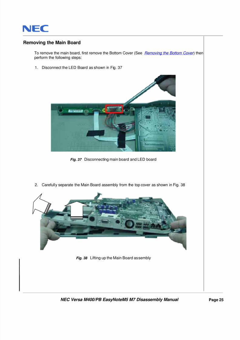
Removing the Main Board
To remove the main board, first remove the Bottom Cover (See Removing the Bottom Cover ) then
perform the following steps:
1. Disconnect the LED Board as shown in Fig. 37
Fig. 37 Disconnecting main board and LED board
2. Carefully separate the Main Board assembly from the top cover as shown in Fig. 38
Fig. 38 Lifting up the Main Board assembly
8/8/2019 36 Service Manual - Packard Bell -Easynote m5 m7 Versa m400
http://slidepdf.com/reader/full/36-service-manual-packard-bell-easynote-m5-m7-versa-m400 27/31
NEC Versa M400/PB EasyNoteM5 M7 Disassembly Manual
Page 26
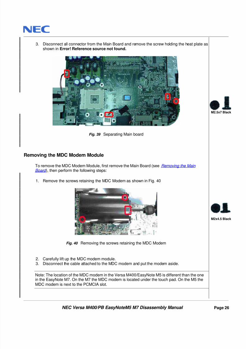
3. Disconnect all connector from the Main Board and remove the screw holding the heat plate asshown in Error! Reference source not found.
Fig. 39 Separating Main board
Removing the MDC Modem Module
To remove the MDC Modem Module, first remove the Main Board (see Removing the Main Board ), then perform the following steps:
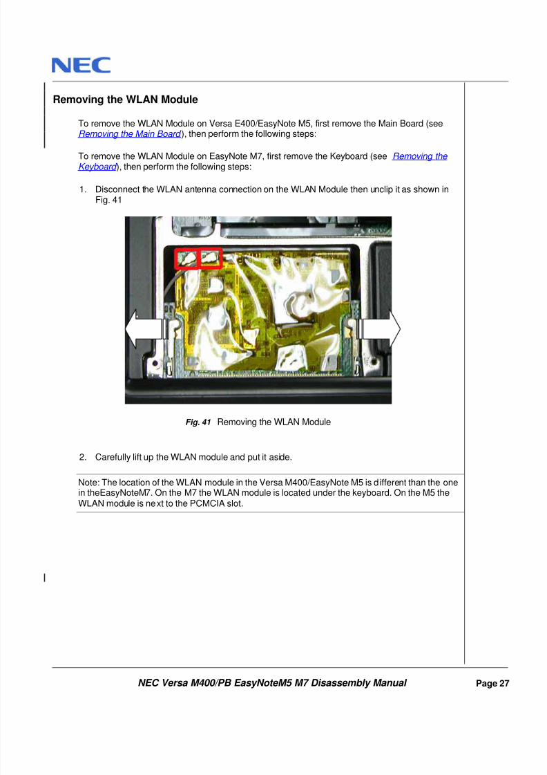
1. Remove the screws retaining the MDC Modem as shown in Fig. 40
Fig. 40 Removing the screws retaining the MDC Modem
2. Carefully lift up the MDC modem module.3. Disconnect the cable attached to the MDC modem and put the modem aside.
Note: The location of the MDC modem in the Versa M400/EasyNote M5 is different than the onein the EasyNote M7. On the M7 the MDC modem is located under the touch pad. On the M5 theMDC modem is next to the PCMCIA slot.
M2.5x7 Black
M2x4.5 Black
8/8/2019 36 Service Manual - Packard Bell -Easynote m5 m7 Versa m400
http://slidepdf.com/reader/full/36-service-manual-packard-bell-easynote-m5-m7-versa-m400 28/31
8/8/2019 36 Service Manual - Packard Bell -Easynote m5 m7 Versa m400
http://slidepdf.com/reader/full/36-service-manual-packard-bell-easynote-m5-m7-versa-m400 29/31
NEC Versa M400/PB EasyNoteM5 M7 Disassembly Manual
Page 28
Removing the Touch Pad
To remove the touch pad, first remove the Main Board (see Removing the Main Board ), then
perform the following steps:
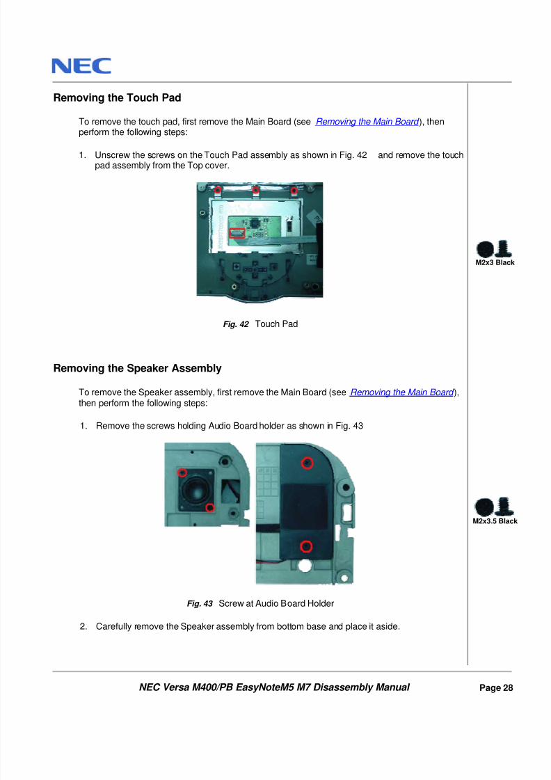
1. Unscrew the screws on the Touch Pad assembly as shown in Fig. 42 and remove the touchpad assembly from the Top cover.
Fig. 42 Touch Pad
Removing the Speaker Assembly
To remove the Speaker assembly, first remove the Main Board (see Removing the Main Board ),then perform the following steps:
1. Remove the screws holding Audio Board holder as shown in Fig. 43
Fig. 43 Screw at Audio Board Holder
2. Carefully remove the Speaker assembly from bottom base and place it aside.
M2x3 Black
M2x3.5 Black
8/8/2019 36 Service Manual - Packard Bell -Easynote m5 m7 Versa m400
http://slidepdf.com/reader/full/36-service-manual-packard-bell-easynote-m5-m7-versa-m400 30/31
NEC Versa M400/PB EasyNoteM5 M7 Disassembly Manual
Page 29
DIP Switch Setting
No DIP Switch settings are available for the Versa M400/EasyNote M5 and EasyNote M7.
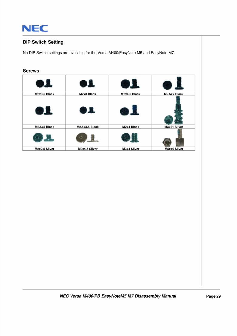
Screws
M2x3.5 Black M2x3 Black M2x4.5 Black M2.5x7 Black
M2.5x5 Black M2.5x3.5 Black M2x4 Black M3x21 Silver
M2x2.5 Silver M2x4.5 Sliver M3x4 Sliver M5x10 Silver
8/8/2019 36 Service Manual - Packard Bell -Easynote m5 m7 Versa m400
http://slidepdf.com/reader/full/36-service-manual-packard-bell-easynote-m5-m7-versa-m400 31/31
NEC Versa M400/PB EasyNoteM5 M7 Disassembly Manual Page 30
Notice
The information in this guide is subject to change without notice.
This guide contains information protected by copyright. No part of this guide may be photocopied or reproduced inany form or by any means without prior written consent from NEC Computers International BV. NEC COMPUTERS INTERNATIONAL BV SHALL NOT BE LIABLE FOR TECHNICAL OR EDITORIAL ERRORSOR OMISSIONS CONTAINED HEREIN; NOR FOR INCIDENTAL OR CONSEQUENTIAL DAMAGES RESULTINGFROM THE FURNISHING, PERFORMANCE, OR USE OF THIS MATERIAL. Copyright © 2003 NEC Computers International BV. All rights reserved. NEC is a trademark of NEC Computers International BV.The names of actual companies and products mentioned herein may be trademarks and/or registered trademarks
of their respective owners.
Versa M400/PB EasyNote M5 M7 Disassembly ManualAuthor: Allen KoayFirst Edition: August 2003Document Part Number:Version: 1.2 NECCMA division of NEC Computers International BV