3.6 Bioretention
30
3.6 Bioretention 99 3.6 Bioretention Definition. Practices that capture and store stormwater runoff and pass it through a filter bed of engineered soil media composed of sand, soil, and organic matter. Filtered runoff may be collected and returned to the conveyance system, or allowed to infiltrate into the soil. Design variants include: B-1 Traditional bioretention B-2 Streetscape bioretention B-3 Engineered tree pits B-4 Stormwater planters B-5 Residential rain gardens Bioretention systems are typically not designed to provide stormwater detention of larger storms (e.g., 2-year, 15-year), but they may be in some circumstances. Bioretention practices shall generally be combined with a separate facility to provide those controls. There are two different types of bioretention design configurations: Standard Designs. Practices with a standard underdrain design and less than 24 inches of filter media depth (see Figure 3.17). If trees are planted using this design, the filter media depth must be at least 24 inches to support the trees. Enhanced Designs. Practices with underdrains that contain at least 24 inches of filter media depth and an infiltration sump/storage layer (see Figure 3.18) or practices that can infiltrate the design storm volume in 72 hours (see Figure 3.19). The particular design configuration to be implemented on a site is typically dependent on specific site conditions and the characteristics of the underlying soils. These criteria are further discussed in this chapter.
Transcript of 3.6 Bioretention

3.6 Bioretention
99
3.6 Bioretention
Definition. Practices that capture and store stormwater runoff and pass it through a filter bed of
engineered soil media composed of sand, soil, and organic matter. Filtered runoff may be
collected and returned to the conveyance system, or allowed to infiltrate into the soil. Design
variants include:
B-1 Traditional bioretention
B-2 Streetscape bioretention
B-3 Engineered tree pits
B-4 Stormwater planters
B-5 Residential rain gardens
Bioretention systems are typically not designed to provide stormwater detention of larger storms
(e.g., 2-year, 15-year), but they may be in some circumstances. Bioretention practices shall
generally be combined with a separate facility to provide those controls.
There are two different types of bioretention design configurations:
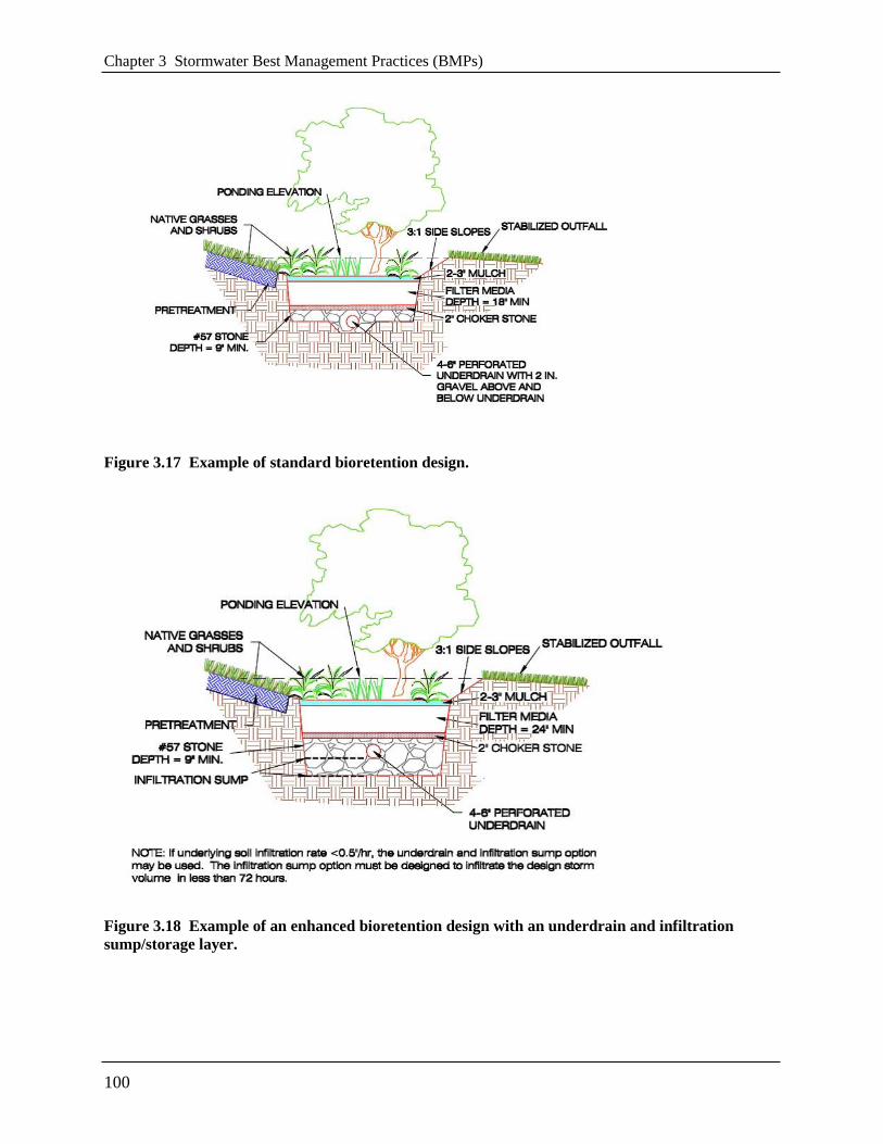
Standard Designs. Practices with a standard underdrain design and less than 24 inches of
filter media depth (see Figure 3.17). If trees are planted using this design, the filter media
depth must be at least 24 inches to support the trees.
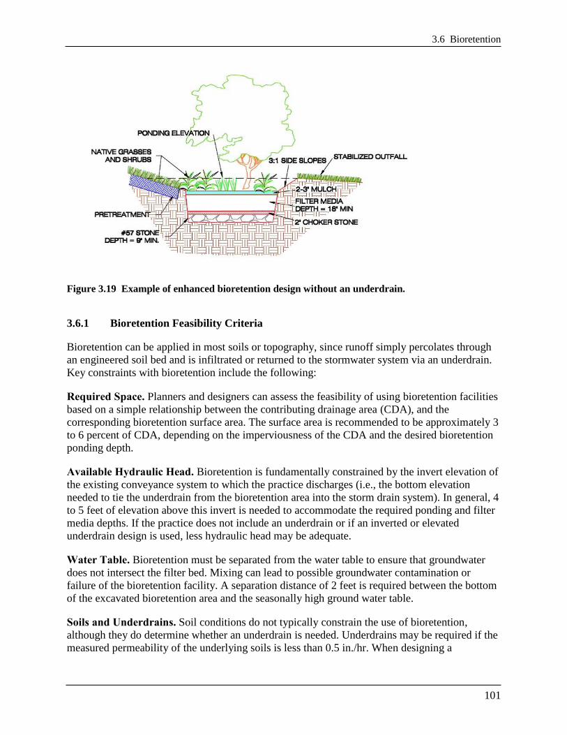
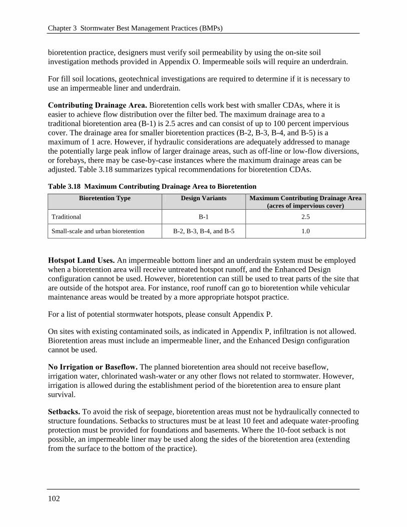
Enhanced Designs. Practices with underdrains that contain at least 24 inches of filter media
depth and an infiltration sump/storage layer (see Figure 3.18) or practices that can infiltrate
the design storm volume in 72 hours (see Figure 3.19).
The particular design configuration to be implemented on a site is typically dependent on
specific site conditions and the characteristics of the underlying soils. These criteria are further
discussed in this chapter.
Chapter 3 Stormwater Best Management Practices (BMPs)
100
Figure 3.17 Example of standard bioretention design.
Figure 3.18 Example of an enhanced bioretention design with an underdrain and infiltration
sump/storage layer.
3.6 Bioretention
101
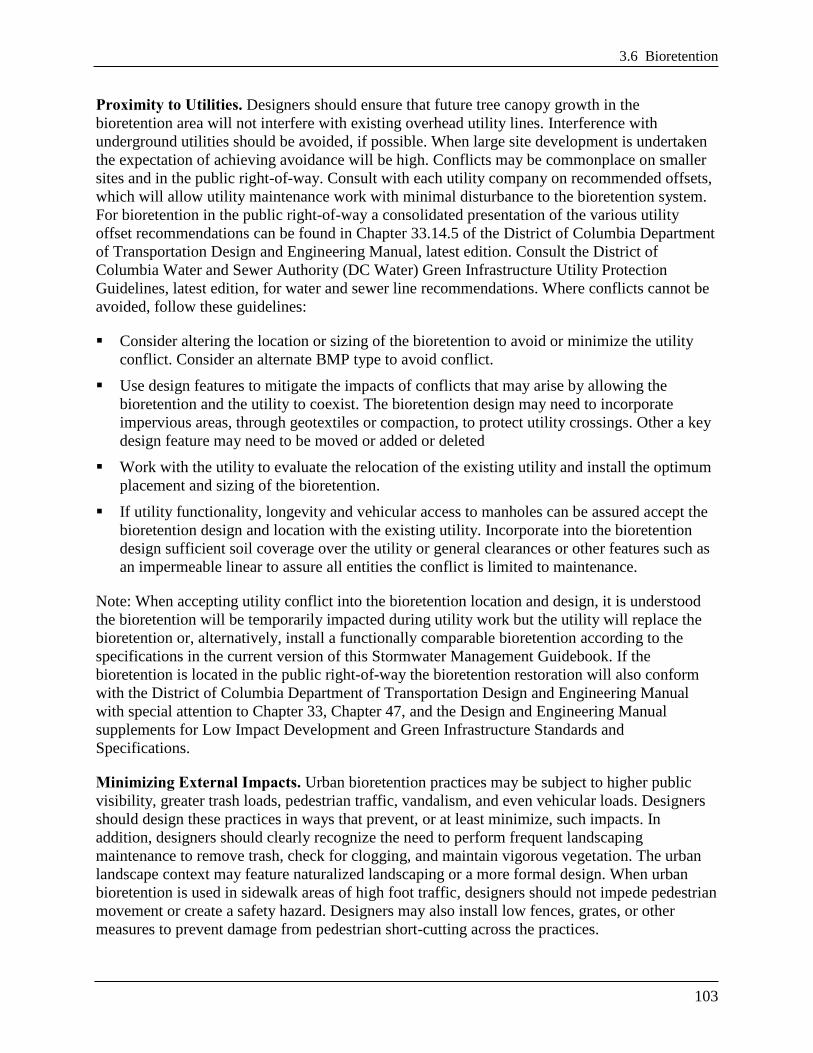
Figure 3.19 Example of enhanced bioretention design without an underdrain.
3.6.1 Bioretention Feasibility Criteria
Bioretention can be applied in most soils or topography, since runoff simply percolates through
an engineered soil bed and is infiltrated or returned to the stormwater system via an underdrain.
Key constraints with bioretention include the following:
Required Space. Planners and designers can assess the feasibility of using bioretention facilities
based on a simple relationship between the contributing drainage area (CDA), and the
corresponding bioretention surface area. The surface area is recommended to be approximately 3
to 6 percent of CDA, depending on the imperviousness of the CDA and the desired bioretention
ponding depth.
Available Hydraulic Head. Bioretention is fundamentally constrained by the invert elevation of
the existing conveyance system to which the practice discharges (i.e., the bottom elevation
needed to tie the underdrain from the bioretention area into the storm drain system). In general, 4
to 5 feet of elevation above this invert is needed to accommodate the required ponding and filter
media depths. If the practice does not include an underdrain or if an inverted or elevated
underdrain design is used, less hydraulic head may be adequate.
Water Table. Bioretention must be separated from the water table to ensure that groundwater
does not intersect the filter bed. Mixing can lead to possible groundwater contamination or
failure of the bioretention facility. A separation distance of 2 feet is required between the bottom
of the excavated bioretention area and the seasonally high ground water table.
Soils and Underdrains. Soil conditions do not typically constrain the use of bioretention,
although they do determine whether an underdrain is needed. Underdrains may be required if the
measured permeability of the underlying soils is less than 0.5 in./hr. When designing a
Chapter 3 Stormwater Best Management Practices (BMPs)
102
bioretention practice, designers must verify soil permeability by using the on-site soil
investigation methods provided in Appendix O. Impermeable soils will require an underdrain.
For fill soil locations, geotechnical investigations are required to determine if it is necessary to
use an impermeable liner and underdrain.
Contributing Drainage Area. Bioretention cells work best with smaller CDAs, where it is
easier to achieve flow distribution over the filter bed. The maximum drainage area to a
traditional bioretention area (B-1) is 2.5 acres and can consist of up to 100 percent impervious
cover. The drainage area for smaller bioretention practices (B-2, B-3, B-4, and B-5) is a
maximum of 1 acre. However, if hydraulic considerations are adequately addressed to manage
the potentially large peak inflow of larger drainage areas, such as off-line or low-flow diversions,
or forebays, there may be case-by-case instances where the maximum drainage areas can be
adjusted. Table 3.18 summarizes typical recommendations for bioretention CDAs.
Table 3.18 Maximum Contributing Drainage Area to Bioretention
Bioretention Type Design Variants Maximum Contributing Drainage Area
(acres of impervious cover)
Traditional B-1 2.5
Small-scale and urban bioretention B-2, B-3, B-4, and B-5 1.0
Hotspot Land Uses. An impermeable bottom liner and an underdrain system must be employed
when a bioretention area will receive untreated hotspot runoff, and the Enhanced Design
configuration cannot be used. However, bioretention can still be used to treat parts of the site that
are outside of the hotspot area. For instance, roof runoff can go to bioretention while vehicular
maintenance areas would be treated by a more appropriate hotspot practice.
For a list of potential stormwater hotspots, please consult Appendix P.
On sites with existing contaminated soils, as indicated in Appendix P, infiltration is not allowed.
Bioretention areas must include an impermeable liner, and the Enhanced Design configuration
cannot be used.
No Irrigation or Baseflow. The planned bioretention area should not receive baseflow,
irrigation water, chlorinated wash-water or any other flows not related to stormwater. However,
irrigation is allowed during the establishment period of the bioretention area to ensure plant
survival.
Setbacks. To avoid the risk of seepage, bioretention areas must not be hydraulically connected to
structure foundations. Setbacks to structures must be at least 10 feet and adequate water-proofing
protection must be provided for foundations and basements. Where the 10-foot setback is not
possible, an impermeable liner may be used along the sides of the bioretention area (extending
from the surface to the bottom of the practice).
3.6 Bioretention
103
Proximity to Utilities. Designers should ensure that future tree canopy growth in the
bioretention area will not interfere with existing overhead utility lines. Interference with
underground utilities should be avoided, if possible. When large site development is undertaken
the expectation of achieving avoidance will be high. Conflicts may be commonplace on smaller
sites and in the public right-of-way. Consult with each utility company on recommended offsets,
which will allow utility maintenance work with minimal disturbance to the bioretention system.
For bioretention in the public right-of-way a consolidated presentation of the various utility
offset recommendations can be found in Chapter 33.14.5 of the District of Columbia Department
of Transportation Design and Engineering Manual, latest edition. Consult the District of
Columbia Water and Sewer Authority (DC Water) Green Infrastructure Utility Protection
Guidelines, latest edition, for water and sewer line recommendations. Where conflicts cannot be
avoided, follow these guidelines:
Consider altering the location or sizing of the bioretention to avoid or minimize the utility
conflict. Consider an alternate BMP type to avoid conflict.
Use design features to mitigate the impacts of conflicts that may arise by allowing the
bioretention and the utility to coexist. The bioretention design may need to incorporate
impervious areas, through geotextiles or compaction, to protect utility crossings. Other a key
design feature may need to be moved or added or deleted
Work with the utility to evaluate the relocation of the existing utility and install the optimum
placement and sizing of the bioretention.
If utility functionality, longevity and vehicular access to manholes can be assured accept the
bioretention design and location with the existing utility. Incorporate into the bioretention
design sufficient soil coverage over the utility or general clearances or other features such as
an impermeable linear to assure all entities the conflict is limited to maintenance.
Note: When accepting utility conflict into the bioretention location and design, it is understood
the bioretention will be temporarily impacted during utility work but the utility will replace the
bioretention or, alternatively, install a functionally comparable bioretention according to the
specifications in the current version of this Stormwater Management Guidebook. If the
bioretention is located in the public right-of-way the bioretention restoration will also conform
with the District of Columbia Department of Transportation Design and Engineering Manual
with special attention to Chapter 33, Chapter 47, and the Design and Engineering Manual
supplements for Low Impact Development and Green Infrastructure Standards and
Specifications.
Minimizing External Impacts. Urban bioretention practices may be subject to higher public
visibility, greater trash loads, pedestrian traffic, vandalism, and even vehicular loads. Designers
should design these practices in ways that prevent, or at least minimize, such impacts. In
addition, designers should clearly recognize the need to perform frequent landscaping
maintenance to remove trash, check for clogging, and maintain vigorous vegetation. The urban
landscape context may feature naturalized landscaping or a more formal design. When urban
bioretention is used in sidewalk areas of high foot traffic, designers should not impede pedestrian
movement or create a safety hazard. Designers may also install low fences, grates, or other
measures to prevent damage from pedestrian short-cutting across the practices.

Chapter 3 Stormwater Best Management Practices (BMPs)
104
When bioretention will be included in public rights-of-way or spaces, design manuals and
guidance developed by agencies or organizations other than DDOE may also apply (e.g., District
Department of Transportation, Office of Planning, and National Capital Planning Commission).
3.6.2 Bioretention Conveyance Criteria
There are two basic design approaches for conveying runoff into, through, and around
bioretention practices:
1. Off-line: Flow is split or diverted so that only the design storm or design flow enters the
bioretention area. Larger flows bypass the bioretention treatment.
2. On-line: All runoff from the drainage area flows into the practice. Flows that exceed the
design capacity exit the practice via an overflow structure or weir.
If runoff is delivered by a storm drain pipe or is along the main conveyance system, the
bioretention area shall be designed off-line so that flows to do not overwhelm or damage the
practice.
Off-line Bioretention. Overflows are diverted from entering the bioretention cell. Optional
diversion methods include the following:
Create an alternate flow path at the inflow point into the structure such that when the
maximum ponding depth is reached, the incoming flow is diverted past the facility. In this
case, the higher flows do not pass over the filter bed and through the facility, and additional
flow is able to enter as the ponding water filters through the soil media. With this design
configuration, an overflow structure in the bioretention area is not required.
Utilize a low-flow diversion or flow splitter at the inlet to allow only the design storm
volume (i.e., the Stormwater Retention Volume (SWRv)) to enter the facility (calculations
must be made to determine the peak flow from the 1.2-inch, 24-hour storm). This may be
achieved with a weir, curb opening, or orifice for the target flow, in combination with a
bypass channel or pipe. Using a weir or curb opening helps minimize clogging and reduces
the maintenance frequency. With this design configuration, an overflow structure in the
bioretention area is required (see on-line bioretention below).
On-line Bioretention. An overflow structure must be incorporated into on-line designs to safely
convey larger storms through the bioretention area. The following criteria apply to overflow
structures:
An overflow shall be provided within the practice to pass storms greater than the design
storm storage to a stabilized water course. A portion of larger events may be managed by the
bioretention area so long as the maximum depth of ponding in the bioretention cell does not
exceed 18 inches.
The overflow device must convey runoff to a storm sewer, stream, or the existing stormwater
conveyance infrastructure, such as curb and gutter or an existing channel.
3.6 Bioretention
105
Common overflow systems within bioretention practices consist of an inlet structure, where
the top of the structure is placed at the maximum ponding depth of the bioretention area,
which is typically 6 to 18 inches above the surface of the filter bed.
The overflow device should be scaled to the application. This may be a landscape grate or
yard inlet for small practices or a commercial-type structure for larger installations.
At least 3–6 inches of freeboard must be provided between the top of the overflow device
and the top of the bioretention area to ensure that nuisance flooding will not occur.
The overflow associated with the 2-year and 15-year design storms must be controlled so that
velocities are non-erosive at the outlet point, to prevent downstream erosion.
3.6.3 Bioretention Pretreatment Criteria
Pretreatment of runoff entering bioretention areas is necessary to trap coarse sediment particles
before they reach and prematurely clog the filter bed. Pretreatment measures must be designed to
evenly spread runoff across the entire width of the bioretention area. Several pretreatment
measures are feasible, depending on the type of the bioretention practice and whether it receives
sheet flow, shallow concentrated flow, or deeper concentrated flows. The following are
appropriate pretreatment options:
Small-Scale Bioretention (B-2, B-3, B-4, and B-5)
Leaf Screens. A leaf screen serves as part of the gutter system to keep the heavy loading of
organic debris from accumulating in the bioretention cell.
Pretreatment Cells (for channel flow). Pretreatment cells are located above ground or
covered by a manhole or grate. Pretreatment cells are atypical in small-scale bioretention and
are not recommended for residential rain gardens (B-5).
Grass Filter Strips (for sheet flow). Grass filter strips are applied on residential lots, where
the lawn area can serve as a grass filter strip adjacent to a rain garden.
Stone Diaphragm (for either sheet flow or concentrated flow). The stone diaphragm at the
end of a downspout or other concentrated inflow point should run perpendicular to the flow
path to promote settling.
Note: stone diaphragms are not recommended for school settings.
Trash Racks (for either sheet flow or concentrated flow).Trash racks are located between the
pretreatment cell and the main filter bed or across curb cuts to allow trash to collect in
specific locations and make maintenance easier.
Traditional Bioretention (B-1)
Pretreatment Cells (for channel flow). Similar to a forebay, this cell is located at piped
inlets or curb cuts leading to the bioretention area and consists of an energy dissipater sized
for the expected rates of discharge. It has a storage volume equivalent to at least 15 percent
of the total storage volume (inclusive) with a recommended 2:1 length-to-width ratio. The
cell may be formed by a wooden or stone check dam or an earthen or rock berm.
Pretreatment cells do not need underlying engineered soil media, in contrast to the main
Chapter 3 Stormwater Best Management Practices (BMPs)
106
bioretention cell. However, if the volume of the pretreatment cell will be included as part of
the bioretention storage volume, the pretreatment cell must de-water between storm events. It
cannot have a permanent ponded volume.
Grass Filter Strips (for sheet flow). Grass filter strips that are perpendicular to incoming
sheet flow extend from the edge of pavement, with a slight drop at the pavement edge, to the
bottom of the bioretention basin at a 5:1 slope or flatter. Alternatively, if the bioretention
basin has side slopes that are 3:1 or flatter, a 5-foot grass filter strip can be used at a
maximum 5 percent (20:1) slope.
Stone Diaphragms (for sheet flow). A stone diaphragm located at the edge of the pavement
should be oriented perpendicular to the flow path to pretreat lateral runoff, with a 2 to 4 inch
drop from the pavement edge to the top of the stone. The stone must be sized according to
the expected rate of discharge.
Gravel or Stone Flow Spreaders (for concentrated flow). The gravel flow spreader is
located at curb cuts, downspouts, or other concentrated inflow points, and should have a 2 to
4 inch elevation drop from a hard-edged surface into a gravel or stone diaphragm. The gravel
must extend the entire width of the opening and create a level stone weir at the bottom or
treatment elevation of the basin.
Filter System (see Section 3.7 Stormwater Filtering Systems). If using a filter system as a
pretreatment facility, the filter will not require a separate pretreatment facility.
Innovative or Proprietary Structure. An approved proprietary structure with demonstrated
capability of reducing sediment and hydrocarbons may be used to provide pretreatment.
Refer to Section 3.13 Proprietary Practices for information on approved proprietary
structures.
Other pretreatment options may be appropriate as long as they trap coarse sediment particles and
evenly spread runoff across the entire width of the bioretention area.
3.6.4 Bioretention Design Criteria
Design Geometry. Bioretention basins must be designed with an internal flow path geometry
such that the treatment mechanisms provided by the bioretention are not bypassed or short-
circuited. In order for the bioretention area to have an acceptable internal geometry, the travel
time from each inlet to the outlet should be maximized by locating the inlets and outlets as far
apart as possible. In addition, incoming flow must be distributed as evenly as possible across the
entire filter surface area.
Inlets and Energy Dissipation. Where appropriate, the inlet(s) to streetscape bioretention (B-2),
engineered tree boxes (B-3), and stormwater planters (B-4) should be stabilized using No. 3
stone, splash block, river stone, or other acceptable energy dissipation measures. The following
types of inlets are recommended:
Downspouts to stone energy dissipaters.
Sheet flow over a depressed curb with a 3-inch drop.
Curb cuts allowing runoff into the bioretention area.
3.6 Bioretention
107
Covered drains that convey flows across sidewalks from the curb or downspouts.
Grates or trench drains that capture runoff from a sidewalk or plaza area.
Drop structures that appropriately dissipate water energy.
Ponding Depth. The recommended surface ponding depth is 6–12 inches. Minimum surface
ponding depth is 3 inches (averaged over the surface area of the BMP). Ponding depths can be
increased to a maximum of 18 inches. However, when higher ponding depths are utilized, the
design must consider carefully issues such as safety, fencing requirements, aesthetics, the
viability and survival of plants, and erosion and scour of side slopes. This is especially true
where bioretention areas are built next to sidewalks or other areas were pedestrians or bicyclists
travel. Shallower ponding depths (typically 6–12 inches) are recommended for streetscape
bioretention (B-2), engineered tree boxes (B-3), and stormwater planters (B-4).
Side Slopes. Traditional bioretention areas (B-1) and residential rain gardens (B-5) should be
constructed with side slopes of 3:1 or flatter. In highly urbanized or space constrained areas, a
drop curb design or a precast structure can be used to create a stable, vertical side wall. These
drop curb designs should not exceed a vertical drop of more than 12 inches, unless safety
precautions, such as railings, walls, grates, etc. are included.
Filter Media. The filter media and surface cover are the two most important elements of a
bioretention facility in terms of long-term performance.
Particle Size Composition. The bioretention soil mixture shall be classified as a loamy sand
on the USDA Texture Triangle, with the following particle size composition:
80–90 percent sand (at least 75 percent of which must be classified as coarse or very
coarse sand)
10–20 percent soil fines (silt and clay)
Maximum 10 percent clay
The particle size analysis must be conducted on the mineral fraction only or following
appropriate treatments to remove organic matter before particle size analysis.
Organic Matter. The filter media must contain 3 to 5 percent organic matter by the
conventional Walkley-Black soil organic matter determination method or similar analysis.
Soil organic matter is expressed on a dry weight basis and does not include coarse particulate
(visible) components.
Available Soil Phosphorus (P). The filter media should contain sufficient available P to
support initial plant establishment and growth, but not serve as a significant source of P for
long-term leaching. Plant-available soil P should be within the range of Low+ (L+) to
Medium (M) as defined in Table 2.2 of Virginia Nutrient Management Standards and Criteria
(2005). For the Mehlich I extraction procedure this equates to a range of 5 to 15 mg/kg P or
18 to 40 mg/kg P for the Mehlich III procedure.
Cation Exchange Capacity (CEC). The relative ability of soils to hold and retain nutrient
cations like Ca and K is referred to as cation exchange capacity (CEC) and is measured as the
total amount of positively charged cations that a soil can hold per unit dry mass. CEC is also
Chapter 3 Stormwater Best Management Practices (BMPs)
108
used as an index of overall soil reactivity and is commonly expressed in milliequivalents per
100 grams (meq/100g) of soil or cmol+/kg (equal values). A soil with a moderate to high
CEC indicates a greater ability to capture and retain positively charged contaminants, which
encourages conditions to remove phosphorus, assuming that soil fines (particularly fine silts
and clays) are at least partially responsible for CEC. The minimum CEC of the filter media is
5.0 (meq/100 g or cmol+/kg). The filter media CEC should be determined by the Unbuffered
Salt, Ammonium Acetate, Summation of Cations or Effective CEC techniques (Sumner and
Miller, 1996) or similar methods that do not utilize strongly acidic extracting solutions.
The goal of the filter media mixture described in this section is to create a soil media that
maintains long-term permeability while also providing enough nutrients to support plant growth.
The initial permeability of the mixture will exceed the desired long-term permeability of 1 to 2
in./hr. The limited amount of topsoil and organic matter is considered adequate to help support
initial plant growth, and it is anticipated that the gradual increase of organic material through
natural processes will continue to support growth while gradually decreasing the permeability.
Finally, the root structure of maturing plants and the biological activity of a self-sustaining
organic content will maintain sufficient long-term permeability as well as support plant growth
without the need to add fertilizer.
The following is the recommended composition of the three media ingredients:
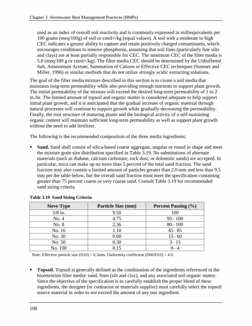
Sand. Sand shall consist of silica-based coarse aggregate, angular or round in shape and meet
the mixture grain size distribution specified in Table 3.19. No substitutions of alternate
materials (such as diabase, calcium carbonate, rock dust, or dolomitic sands) are accepted. In
particular, mica can make up no more than 5 percent of the total sand fraction. The sand
fraction may also contain a limited amount of particles greater than 2.0 mm and less than 9.5
mm per the table below, but the overall sand fraction must meet the specification containing
greater than 75 percent coarse or very coarse sand. Consult Table 3.19 for recommended
sand sizing criteria.
Table 3.19 Sand Sizing Criteria
Sieve Type Particle Size (mm) Percent Passing (%)
3/8 in. 9.50 100
No. 4 4.75 95– 100
No. 8 2.36 80– 100
No. 16 1.18 45– 85
No. 30 0.60 15– 60
No. 50 0.30 3– 15
No. 100 0.15 0– 4
Note: Effective particle size (D10) > 0.3mm. Uniformity coefficient (D60/D10) < 4.0.
Topsoil. Topsoil is generally defined as the combination of the ingredients referenced in the
bioretention filter media: sand, fines (silt and clay), and any associated soil organic matter.
Since the objective of the specification is to carefully establish the proper blend of these
ingredients, the designer (or contractor or materials supplier) must carefully select the topsoil
source material in order to not exceed the amount of any one ingredient.
3.6 Bioretention
109
Generally, the use of a topsoil defined as a loamy sand, sandy loam, or loam (per the USDA
Textural Triangle) will be an acceptable ingredient and in combination with the other
ingredients meet the overall performance goal of the soil media.
Organic Matter. Organic materials used in the soil media mix should consist of well-
decomposed natural C-containing organic materials such as peat moss, humus, compost
(consistent with the material specifications found in Appendix J), pine bark fines or other
organic soil conditioning material. However, per above, the combined filter media should
contain 3 to 5 percent soil organic matter on dry weight basis (grams organic matter per 100
grams dry soil) by the Walkley-Black method or other similar analytical technique.
In creating the filter media, it is recommended to start with an open-graded coarse sand
material and proportionately mix in the topsoil materials to achieve the desired ratio of sand
and fines. Sufficient suitable organic amendments can then be added to achieve the 3 to 5
percent soil organic matter target. The exact composition of organic matter and topsoil
material will vary, making the exact particle size distribution of the final total soil media
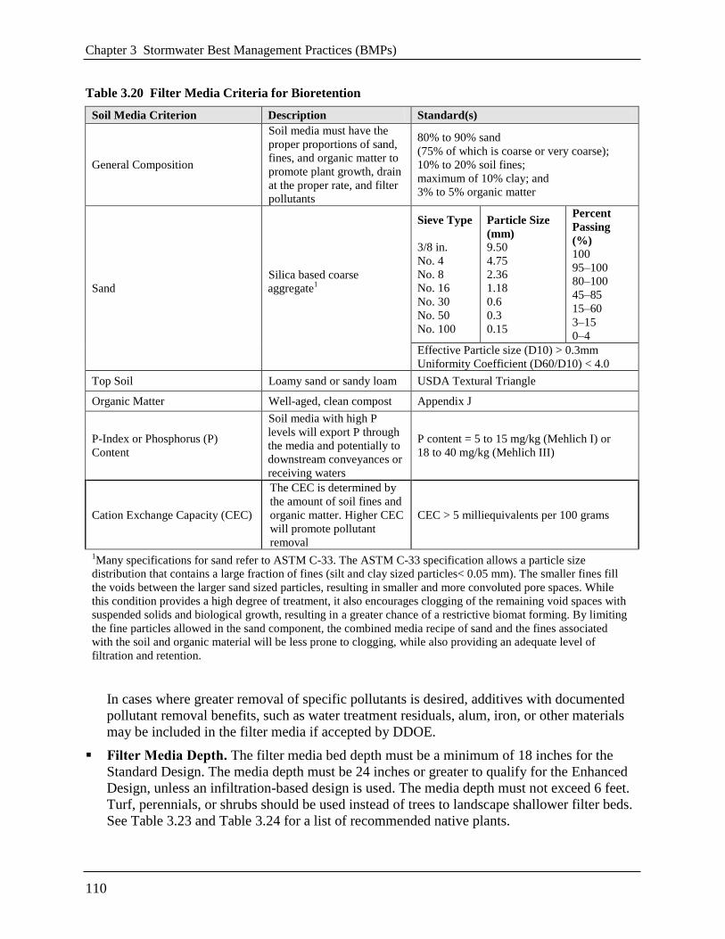
mixture difficult to define in advance of evaluating available materials. Table 3.20
summarizes the filter media requirements.
Chapter 3 Stormwater Best Management Practices (BMPs)
110
Table 3.20 Filter Media Criteria for Bioretention
Soil Media Criterion Description Standard(s)
General Composition
Soil media must have the
proper proportions of sand,
fines, and organic matter to
promote plant growth, drain
at the proper rate, and filter
pollutants
80% to 90% sand
(75% of which is coarse or very coarse);
10% to 20% soil fines;
maximum of 10% clay; and
3% to 5% organic matter
Sand
Silica based coarse
aggregate1
Sieve Type
3/8 in.
No. 4
No. 8
No. 16
No. 30
No. 50
No. 100
Particle Size
(mm)
9.50
4.75
2.36
1.18
0.6
0.3
0.15
Percent
Passing
(%)
100
95–100
80–100
45–85
15–60
3–15
0–4
Effective Particle size (D10) > 0.3mm
Uniformity Coefficient (D60/D10) < 4.0
Top Soil Loamy sand or sandy loam USDA Textural Triangle
Organic Matter Well-aged, clean compost Appendix J
P-Index or Phosphorus (P)
Content
Soil media with high P
levels will export P through
the media and potentially to
downstream conveyances or
receiving waters
P content = 5 to 15 mg/kg (Mehlich I) or
18 to 40 mg/kg (Mehlich III)
Cation Exchange Capacity (CEC)
The CEC is determined by
the amount of soil fines and
organic matter. Higher CEC
will promote pollutant
removal
CEC > 5 milliequivalents per 100 grams
1Many specifications for sand refer to ASTM C-33. The ASTM C-33 specification allows a particle size
distribution that contains a large fraction of fines (silt and clay sized particles< 0.05 mm). The smaller fines fill
the voids between the larger sand sized particles, resulting in smaller and more convoluted pore spaces. While
this condition provides a high degree of treatment, it also encourages clogging of the remaining void spaces with
suspended solids and biological growth, resulting in a greater chance of a restrictive biomat forming. By limiting
the fine particles allowed in the sand component, the combined media recipe of sand and the fines associated
with the soil and organic material will be less prone to clogging, while also providing an adequate level of
filtration and retention.
In cases where greater removal of specific pollutants is desired, additives with documented
pollutant removal benefits, such as water treatment residuals, alum, iron, or other materials
may be included in the filter media if accepted by DDOE.
Filter Media Depth. The filter media bed depth must be a minimum of 18 inches for the
Standard Design. The media depth must be 24 inches or greater to qualify for the Enhanced
Design, unless an infiltration-based design is used. The media depth must not exceed 6 feet.
Turf, perennials, or shrubs should be used instead of trees to landscape shallower filter beds.
See Table 3.23 and Table 3.24 for a list of recommended native plants.
3.6 Bioretention
111
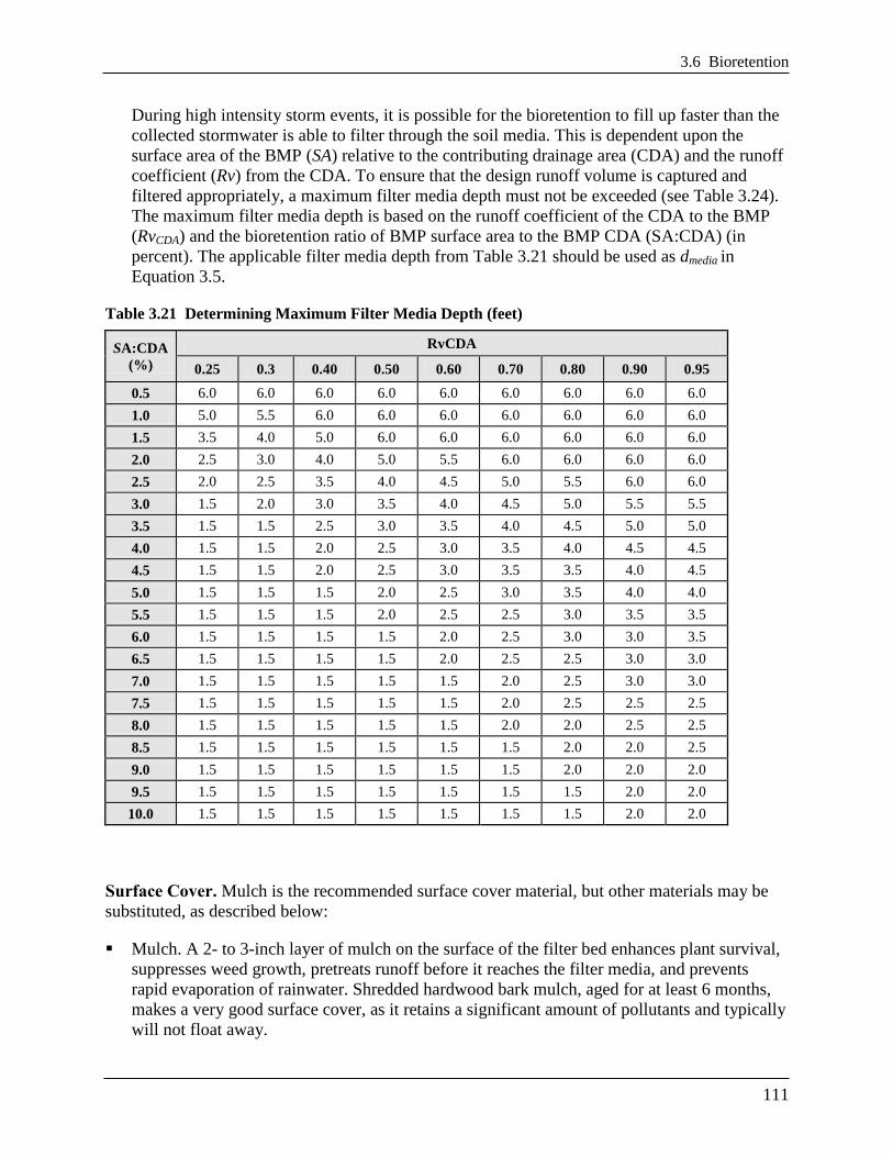
During high intensity storm events, it is possible for the bioretention to fill up faster than the
collected stormwater is able to filter through the soil media. This is dependent upon the
surface area of the BMP (SA) relative to the contributing drainage area (CDA) and the runoff
coefficient (Rv) from the CDA. To ensure that the design runoff volume is captured and
filtered appropriately, a maximum filter media depth must not be exceeded (see Table 3.24).
The maximum filter media depth is based on the runoff coefficient of the CDA to the BMP
(RvCDA) and the bioretention ratio of BMP surface area to the BMP CDA (SA:CDA) (in
percent). The applicable filter media depth from Table 3.21 should be used as dmedia in
Equation 3.5.
Table 3.21 Determining Maximum Filter Media Depth (feet)
SA:CDA
(%)
RvCDA
0.25 0.3 0.40 0.50 0.60 0.70 0.80 0.90 0.95
0.5 6.0 6.0 6.0 6.0 6.0 6.0 6.0 6.0 6.0
1.0 5.0 5.5 6.0 6.0 6.0 6.0 6.0 6.0 6.0
1.5 3.5 4.0 5.0 6.0 6.0 6.0 6.0 6.0 6.0
2.0 2.5 3.0 4.0 5.0 5.5 6.0 6.0 6.0 6.0
2.5 2.0 2.5 3.5 4.0 4.5 5.0 5.5 6.0 6.0
3.0 1.5 2.0 3.0 3.5 4.0 4.5 5.0 5.5 5.5
3.5 1.5 1.5 2.5 3.0 3.5 4.0 4.5 5.0 5.0
4.0 1.5 1.5 2.0 2.5 3.0 3.5 4.0 4.5 4.5
4.5 1.5 1.5 2.0 2.5 3.0 3.5 3.5 4.0 4.5
5.0 1.5 1.5 1.5 2.0 2.5 3.0 3.5 4.0 4.0
5.5 1.5 1.5 1.5 2.0 2.5 2.5 3.0 3.5 3.5
6.0 1.5 1.5 1.5 1.5 2.0 2.5 3.0 3.0 3.5
6.5 1.5 1.5 1.5 1.5 2.0 2.5 2.5 3.0 3.0
7.0 1.5 1.5 1.5 1.5 1.5 2.0 2.5 3.0 3.0
7.5 1.5 1.5 1.5 1.5 1.5 2.0 2.5 2.5 2.5
8.0 1.5 1.5 1.5 1.5 1.5 2.0 2.0 2.5 2.5
8.5 1.5 1.5 1.5 1.5 1.5 1.5 2.0 2.0 2.5
9.0 1.5 1.5 1.5 1.5 1.5 1.5 2.0 2.0 2.0
9.5 1.5 1.5 1.5 1.5 1.5 1.5 1.5 2.0 2.0
10.0 1.5 1.5 1.5 1.5 1.5 1.5 1.5 2.0 2.0
Surface Cover. Mulch is the recommended surface cover material, but other materials may be
substituted, as described below:
Mulch. A 2- to 3-inch layer of mulch on the surface of the filter bed enhances plant survival,
suppresses weed growth, pretreats runoff before it reaches the filter media, and prevents
rapid evaporation of rainwater. Shredded hardwood bark mulch, aged for at least 6 months,
makes a very good surface cover, as it retains a significant amount of pollutants and typically
will not float away.
Chapter 3 Stormwater Best Management Practices (BMPs)
112
Alternative to Mulch Cover. In some situations, designers may consider alternative surface
covers, such as turf, native groundcover, erosion control matting (e.g., coir or jute matting),
river stone, or pea gravel. The decision regarding the type of surface cover to use should be
based on function, expected pedestrian traffic, cost, and maintenance. When alternative
surface covers are used, methods to discourage pedestrian traffic should be considered. Stone
or gravel are not recommended in parking lot applications, since they increase soil
temperature and have low water-holding capacity.
Media for Turf Cover. One adaptation suggested for use with turf cover is to design the filter
media primarily as a sand filter with organic content only at the top. Compost, as specified in
Appendix J, tilled into the top layers will provide organic content for the vegetative cover. If
grass is the only vegetation, the ratio of organic matter in the filter media composition may
be reduced.
Choking Layer. A 2 to 4 inch layer of choker stone (e.g., typically ASTM D448 No. 8 or No. 89
washed gravel) should be placed beneath the soil media and over the underdrain stone.
Geotextile. If the available head is limited, or the depth of the practice is a concern, geotextile
fabric may be used in place of the choking layer. An appropriate geotextile fabric that complies
with AASHTO M-288 Class 2, latest edition, requirements, and has a permeability of at least an
order of magnitude higher (10x) than the soil subgrade permeability must be used. Geotextile
fabric may be used on the sides of bioretention areas, as well.
Underdrains. Many bioretention designs will require an underdrain (see Section 3.6.1
Bioretention Feasibility Criteria). The underdrain should be a 4- or 6-inch perforated schedule 40
PVC pipe, or equivalent corrugated HDPE for small bioretention BMPs, with 3/8-inch
perforations at 6 inches on center. The underdrain must be encased in a layer of clean, double
washed ASTM D448 No.57 or smaller (No. 68, 8, or 89) stone. The underdrain must be sized so
that the bioretention BMP fully drains within 72 hours or less.
Multiple underdrains are necessary for bioretention areas wider than 40 feet, and each underdrain
must be located no more than 20 feet from the next pipe or the edge of the bioretention. (For long
and narrow applications, a single underdrain running the length of the bioretention is sufficient.)
All traditional bioretention practices must include at least one observation well and/or cleanout
pipe (minimum 4 inches in diameter). The observation wells should be tied into any of the Ts or
Ys in the underdrain system and must extend upward above the surface of the bioretention area.
Underground Storage Layer (optional). For bioretention systems with an underdrain, an
underground storage layer consisting of chambers, perforated pipe, stone, or other acceptable
material can be incorporated below the filter media layer and underdrain to increase the
infiltration sump volume or the storage for larger storm events. To qualify for the Enhanced
Design, this storage layer must be designed to infiltrate in 72 hours, at ½ the measured
infiltration rate. The may also be designed to provide detention for the 2-year, 15-year, or 100-
year storms, as needed. The depth and volume of the storage layer will then depend on the target
storage volumes needed to meet the applicable detention criteria.
3.6 Bioretention
113
Impermeable Liner. An impermeable liner is not typically required, although it may be utilized
in fill applications where deemed necessary by a geotechnical investigation, on sites with
contaminated soils, or on the sides of the practice to protect adjacent structures from seepage.
Use a 30-mililiter (minimum) PVC geomembrane liner. (Follow manufacturer’s instructions for
installation.) Field seams must be sealed according to the liner manufacturer’s specifications. A
minimum 6-inch overlap of material is required at all seams.
Material Specifications. Recommended material specifications for bioretention areas are shown
in Table 3.22.
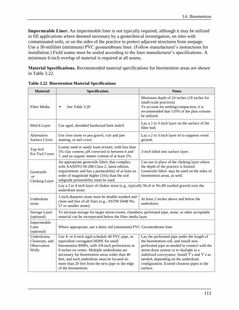
Table 3.22 Bioretention Material Specifications
Material Specification Notes
Filter Media See Table 3.20
Minimum depth of 24 inches (18 inches for
small-scale practices)
To account for settling/compaction, it is
recommended that 110% of the plan volume
be utilized.
Mulch Layer Use aged, shredded hardwood bark mulch Lay a 2 to 3-inch layer on the surface of the
filter bed.
Alternative
Surface Cover
Use river stone or pea gravel, coir and jute
matting, or turf cover.
Lay a 2 to 3-inch layer of to suppress weed
growth.
Top Soil
For Turf Cover
Loamy sand or sandy loam texture, with less than
5% clay content, pH corrected to between 6 and
7, and an organic matter content of at least 2%.
3-inch tilled into surface layer.
Geotextile
or
Choking Layer
An appropriate geotextile fabric that complies
with AASHTO M-288 Class 2, latest edition,
requirements and has a permeability of at least an
order of magnitude higher (10x) than the soil
subgrade permeability must be used
Can use in place of the choking layer where
the depth of the practice is limited. Geotextile fabric may be used on the sides of
bioretention areas, as well.
Lay a 2 to 4 inch layer of choker stone (e.g., typically No.8 or No.89 washed gravel) over the
underdrain stone.
Underdrain
stone
1-inch diameter stone must be double-washed and
clean and free of all fines (e.g., ASTM D448 No.
57 or smaller stone).
At least 2 inches above and below the
underdrain.
Storage Layer
(optional)
To increase storage for larger storm events, chambers, perforated pipe, stone, or other acceptable
material can be incorporated below the filter media layer
Impermeable
Liner
(optional)
Where appropriate, use a thirty mil (minimum) PVC Geomembrane liner
Underdrains,
Cleanouts, and
Observation
Wells
Use 4- or 6-inch rigid schedule 40 PVC pipe, or
equivalent corrugated HDPE for small
bioretention BMPs, with 3/8-inch perforations at
6 inches on center. Multiple underdrains are
necessary for bioretention areas wider than 40
feet, and each underdrain must be located no
more than 20 feet from the next pipe or the edge
of the bioretention.
Lay the perforated pipe under the length of
the bioretention cell, and install non-
perforated pipe as needed to connect with the
storm drain system or to daylight in a
stabilized conveyance. Install T’s and Y’s as
needed, depending on the underdrain
configuration. Extend cleanout pipes to the
surface.
Chapter 3 Stormwater Best Management Practices (BMPs)
114
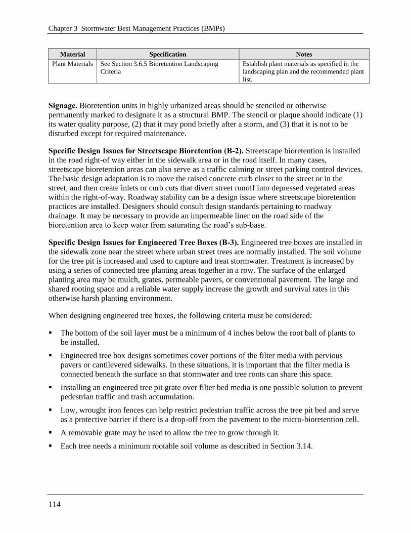
Material Specification Notes
Plant Materials See Section 3.6.5 Bioretention Landscaping
Criteria
Establish plant materials as specified in the
landscaping plan and the recommended plant
list.
Signage. Bioretention units in highly urbanized areas should be stenciled or otherwise
permanently marked to designate it as a structural BMP. The stencil or plaque should indicate (1)
its water quality purpose, (2) that it may pond briefly after a storm, and (3) that it is not to be
disturbed except for required maintenance.
Specific Design Issues for Streetscape Bioretention (B-2). Streetscape bioretention is installed
in the road right-of way either in the sidewalk area or in the road itself. In many cases,
streetscape bioretention areas can also serve as a traffic calming or street parking control devices.
The basic design adaptation is to move the raised concrete curb closer to the street or in the
street, and then create inlets or curb cuts that divert street runoff into depressed vegetated areas
within the right-of-way. Roadway stability can be a design issue where streetscape bioretention
practices are installed. Designers should consult design standards pertaining to roadway
drainage. It may be necessary to provide an impermeable liner on the road side of the
bioretention area to keep water from saturating the road’s sub-base.
Specific Design Issues for Engineered Tree Boxes (B-3). Engineered tree boxes are installed in
the sidewalk zone near the street where urban street trees are normally installed. The soil volume
for the tree pit is increased and used to capture and treat stormwater. Treatment is increased by
using a series of connected tree planting areas together in a row. The surface of the enlarged
planting area may be mulch, grates, permeable pavers, or conventional pavement. The large and
shared rooting space and a reliable water supply increase the growth and survival rates in this
otherwise harsh planting environment.
When designing engineered tree boxes, the following criteria must be considered:
The bottom of the soil layer must be a minimum of 4 inches below the root ball of plants to
be installed.
Engineered tree box designs sometimes cover portions of the filter media with pervious
pavers or cantilevered sidewalks. In these situations, it is important that the filter media is
connected beneath the surface so that stormwater and tree roots can share this space.
Installing an engineered tree pit grate over filter bed media is one possible solution to prevent
pedestrian traffic and trash accumulation.
Low, wrought iron fences can help restrict pedestrian traffic across the tree pit bed and serve
as a protective barrier if there is a drop-off from the pavement to the micro-bioretention cell.
A removable grate may be used to allow the tree to grow through it.
Each tree needs a minimum rootable soil volume as described in Section 3.14.
3.6 Bioretention
115
Specific Design Issues for Stormwater Planters (B-4). Stormwater planters are a useful option
to disconnect and treat rooftop runoff, particularly in ultra-urban areas. They consist of confined
planters that store and/or infiltrate runoff in a soil bed to reduce runoff volumes and pollutant
loads. Stormwater planters combine an aesthetic landscaping feature with a functional form of
stormwater treatment. Stormwater planters generally receive runoff from adjacent rooftop
downspouts and are landscaped with plants that are tolerant to periods of both drought and
inundation. The two basic design variations for stormwater planters are the infiltration planter
and the filter planter. A filter planter is illustrated in Figure 3.2 below.
An infiltration planter filters rooftop runoff through soil in the planter followed by infiltration
into soils below the planter. The minimum filter media depth is 18 inches, with the shape and
length determined by architectural considerations. Infiltration planters should be placed at least
10 feet away from a building to prevent possible flooding or basement seepage damage.
A filter planter does not allow for infiltration and is constructed with a watertight concrete shell
or an impermeable liner on the bottom to prevent seepage. Since a filter planter is self-contained
and does not infiltrate into the ground, it can be installed right next to a building. The minimum
filter media depth is 18 inches, with the shape and length determined by architectural
considerations. Runoff is captured and temporarily ponded above the planter bed. Overflow
pipes are installed to discharge runoff when maximum ponding depths are exceeded, to avoid
water spilling over the side of the planter. In addition, an underdrain is used to carry runoff to the
storm sewer system.
Chapter 3 Stormwater Best Management Practices (BMPs)
116
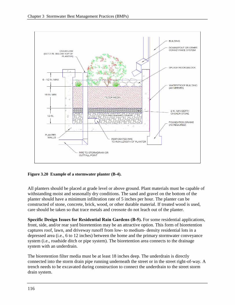
Figure 3.20 Example of a stormwater planter (B-4).
All planters should be placed at grade level or above ground. Plant materials must be capable of
withstanding moist and seasonally dry conditions. The sand and gravel on the bottom of the
planter should have a minimum infiltration rate of 5 inches per hour. The planter can be
constructed of stone, concrete, brick, wood, or other durable material. If treated wood is used,
care should be taken so that trace metals and creosote do not leach out of the planter.
Specific Design Issues for Residential Rain Gardens (B-5). For some residential applications,
front, side, and/or rear yard bioretention may be an attractive option. This form of bioretention
captures roof, lawn, and driveway runoff from low- to medium- density residential lots in a
depressed area (i.e., 6 to 12 inches) between the home and the primary stormwater conveyance
system (i.e., roadside ditch or pipe system). The bioretention area connects to the drainage
system with an underdrain.
The bioretention filter media must be at least 18 inches deep. The underdrain is directly
connected into the storm drain pipe running underneath the street or in the street right-of-way. A
trench needs to be excavated during construction to connect the underdrain to the street storm
drain system.
3.6 Bioretention
117
Construction of the remainder of the bioretention system is deferred until after the lot has been
stabilized. Residential rain gardens require regular maintenance to perform effectively.
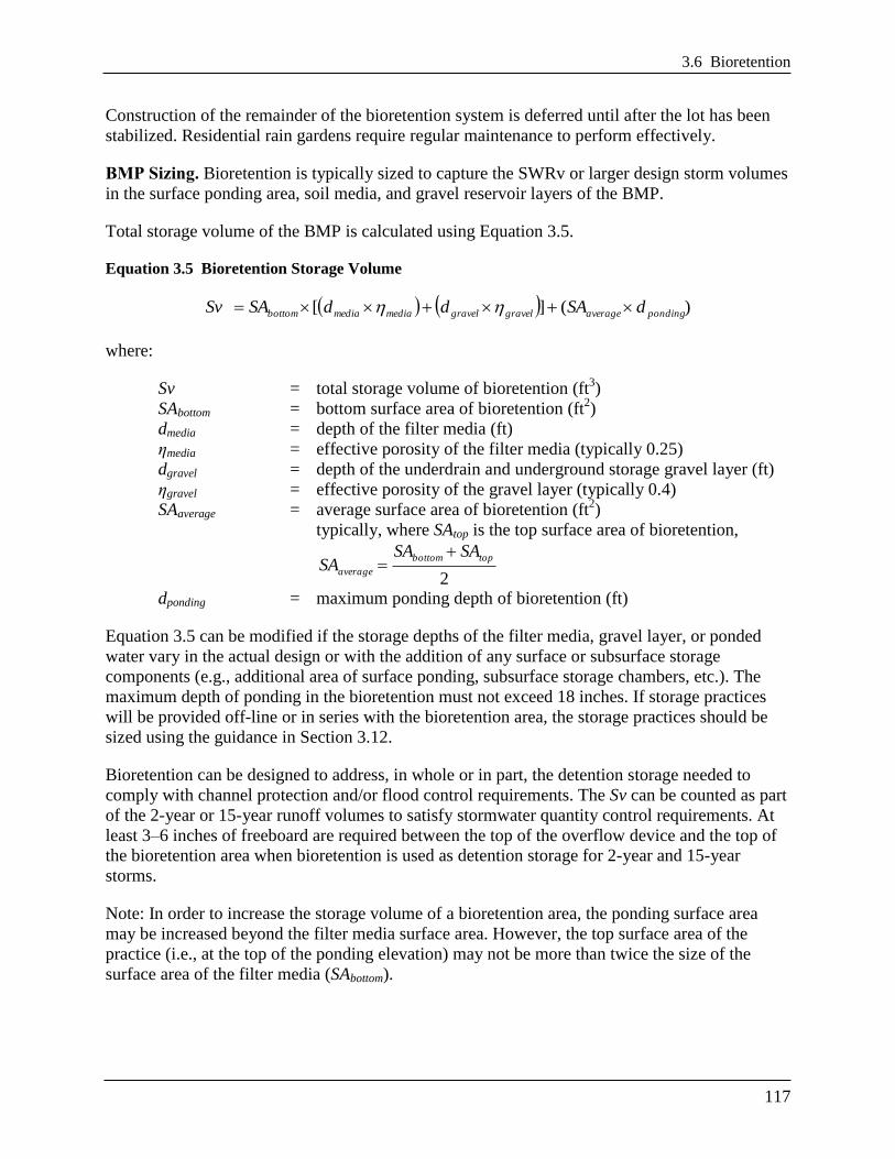
BMP Sizing. Bioretention is typically sized to capture the SWRv or larger design storm volumes
in the surface ponding area, soil media, and gravel reservoir layers of the BMP.
Total storage volume of the BMP is calculated using Equation 3.5.
Equation 3.5 Bioretention Storage Volume
)(][ pondingaveragegravelgravelmediamediabottom dSAddSASv
where:
Sv = total storage volume of bioretention (ft3)
SAbottom = bottom surface area of bioretention (ft2)
dmedia = depth of the filter media (ft)
ηmedia = effective porosity of the filter media (typically 0.25)
dgravel = depth of the underdrain and underground storage gravel layer (ft)
ηgravel = effective porosity of the gravel layer (typically 0.4)
SAaverage = average surface area of bioretention (ft2)
typically, where SAtop is the top surface area of bioretention,
2
topbottom
average
SASASA
dponding = maximum ponding depth of bioretention (ft)
Equation 3.5 can be modified if the storage depths of the filter media, gravel layer, or ponded
water vary in the actual design or with the addition of any surface or subsurface storage
components (e.g., additional area of surface ponding, subsurface storage chambers, etc.). The
maximum depth of ponding in the bioretention must not exceed 18 inches. If storage practices
will be provided off-line or in series with the bioretention area, the storage practices should be
sized using the guidance in Section 3.12.
Bioretention can be designed to address, in whole or in part, the detention storage needed to
comply with channel protection and/or flood control requirements. The Sv can be counted as part
of the 2-year or 15-year runoff volumes to satisfy stormwater quantity control requirements. At
least 3–6 inches of freeboard are required between the top of the overflow device and the top of
the bioretention area when bioretention is used as detention storage for 2-year and 15-year
storms.
Note: In order to increase the storage volume of a bioretention area, the ponding surface area
may be increased beyond the filter media surface area. However, the top surface area of the
practice (i.e., at the top of the ponding elevation) may not be more than twice the size of the
surface area of the filter media (SAbottom).
Chapter 3 Stormwater Best Management Practices (BMPs)
118
3.6.5 Bioretention Landscaping Criteria
Landscaping is critical to the performance and function of bioretention areas. Therefore, a
landscaping plan shall be provided for bioretention areas.
Minimum plan elements include the proposed bioretention template to be used, delineation of
planting areas, and the planting plan including the following:
Common and botanical names of the plants used
Size of planted materials
Mature size of the plants
Light requirements
Maintenance requirements
Source of planting stock
Any other specifications
Planting sequence
It is recommended that the planting plan be prepared by a qualified landscape architect
professional (e.g. licensed professional landscape architect, certified horticulturalist) in order to
tailor the planting plan to the site-specific conditions.
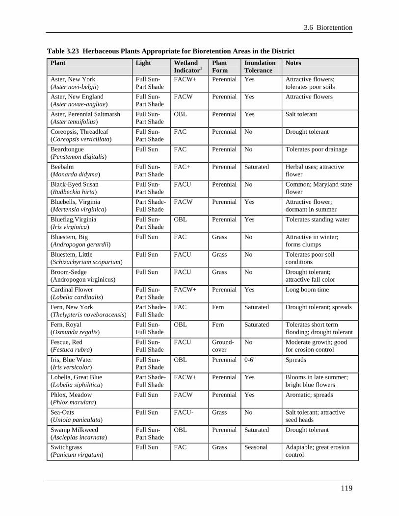
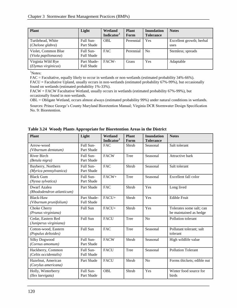
Native plant species are preferred over non-native species, but some ornamental species may be
used for landscaping effect if they are not aggressive or invasive. Some popular native species
that work well in bioretention areas and are commercially available can be found in Table 3.23
and Table 3.24. Internet links to more detailed bioretention plant lists developed in the
Chesapeake Bay region are provided below:
Prince Georges County, MD
http://www.aacounty.org/DPW/Highways/Resources/Raingarden/RG_Bioretention_PG%20
CO.pdf
Delaware Green Technology Standards and Specifications
http://www.dnrec.state.de.us/DNREC2000/Divisions/Soil/Stormwater/New/GT_Stds%20&%
20Specs_06-05.pdf
The degree of landscape maintenance that can be provided will determine some of the planting
choices for urban bioretention areas. Plant selection differs if the area will be frequently mowed,
pruned, and weeded, in contrast to a site which will receive minimum annual maintenance. In
areas where less maintenance will be provided and where trash accumulation in shrubbery or
herbaceous plants is a concern, consider a ―turf and trees‖ landscaping model where the turf is
mowed along with other turf areas on the site. Spaces for herbaceous flowering plants can be
included.
3.6 Bioretention
119
Table 3.23 Herbaceous Plants Appropriate for Bioretention Areas in the District
Plant Light Wetland
Indicator1
Plant
Form
Inundation
Tolerance
Notes
Aster, New York
(Aster novi-belgii)
Full Sun-
Part Shade
FACW+ Perennial Yes Attractive flowers;
tolerates poor soils
Aster, New England
(Aster novae-angliae)
Full Sun-
Part Shade
FACW Perennial Yes Attractive flowers
Aster, Perennial Saltmarsh
(Aster tenuifolius)
Full Sun-
Part Shade
OBL Perennial Yes Salt tolerant
Coreopsis, Threadleaf
(Coreopsis verticillata)
Full Sun-
Part Shade
FAC Perennial No Drought tolerant
Beardtongue
(Penstemon digitalis)
Full Sun FAC Perennial No Tolerates poor drainage
Beebalm
(Monarda didyma)
Full Sun-
Part Shade
FAC+ Perennial Saturated Herbal uses; attractive
flower
Black-Eyed Susan
(Rudbeckia hirta)
Full Sun-
Part Shade
FACU Perennial No Common; Maryland state
flower
Bluebells, Virginia
(Mertensia virginica)
Part Shade-
Full Shade
FACW Perennial Yes Attractive flower;
dormant in summer
Blueflag,Virginia
(Iris virginica)
Full Sun-
Part Shade
OBL Perennial Yes Tolerates standing water
Bluestem, Big
(Andropogon gerardii)
Full Sun FAC Grass No Attractive in winter;
forms clumps
Bluestem, Little
(Schizachyrium scoparium)
Full Sun FACU Grass No Tolerates poor soil
conditions
Broom-Sedge
(Andropogon virginicus)
Full Sun FACU Grass No Drought tolerant;
attractive fall color
Cardinal Flower
(Lobelia cardinalis)
Full Sun-
Part Shade
FACW+ Perennial Yes Long boom time
Fern, New York
(Thelypteris noveboracensis)
Part Shade-
Full Shade
FAC Fern Saturated Drought tolerant; spreads
Fern, Royal
(Osmunda regalis)
Full Sun-
Full Shade
OBL Fern Saturated Tolerates short term
flooding; drought tolerant
Fescue, Red
(Festuca rubra)
Full Sun-
Full Shade
FACU Ground-
cover
No Moderate growth; good
for erosion control
Iris, Blue Water
(Iris versicolor)
Full Sun-
Part Shade
OBL Perennial 0-6" Spreads
Lobelia, Great Blue
(Lobelia siphilitica)
Part Shade-
Full Shade
FACW+ Perennial Yes Blooms in late summer;
bright blue flowers
Phlox, Meadow
(Phlox maculata)
Full Sun FACW Perennial Yes Aromatic; spreads
Sea-Oats
(Uniola paniculata)
Full Sun FACU- Grass No Salt tolerant; attractive
seed heads
Swamp Milkweed
(Asclepias incarnata)
Full Sun-
Part Shade
OBL Perennial Saturated Drought tolerant
Switchgrass
(Panicum virgatum)
Full Sun FAC Grass Seasonal Adaptable; great erosion
control
Chapter 3 Stormwater Best Management Practices (BMPs)
120
Plant Light Wetland
Indicator1
Plant
Form
Inundation
Tolerance
Notes
Turtlehead, White
(Chelone glabra)
Full Sun-
Part Shade
OBL Perennial Yes Excellent growth; herbal
uses
Violet, Common Blue
(Viola papilionacea)
Full Sun-
Full Shade
FAC Perennial No Stemless; spreads
Virginia Wild Rye
(Elymus virginicus)
Part Shade-
Full Shade
FACW- Grass Yes Adaptable
1Notes:
FAC = Facultative, equally likely to occur in wetlands or non-wetlands (estimated probability 34%-66%).
FACU = Facultative Upland, usually occurs in non-wetlands (estimated probability 67%-99%), but occasionally
found on wetlands (estimated probability 1%-33%).
FACW = FACW Facultative Wetland, usually occurs in wetlands (estimated probability 67%-99%), but
occasionally found in non-wetlands.
OBL = Obligate Wetland, occurs almost always (estimated probability 99%) under natural conditions in wetlands.
Sources: Prince George’s County Maryland Bioretention Manual; Virginia DCR Stormwater Design Specification
No. 9: Bioretention.
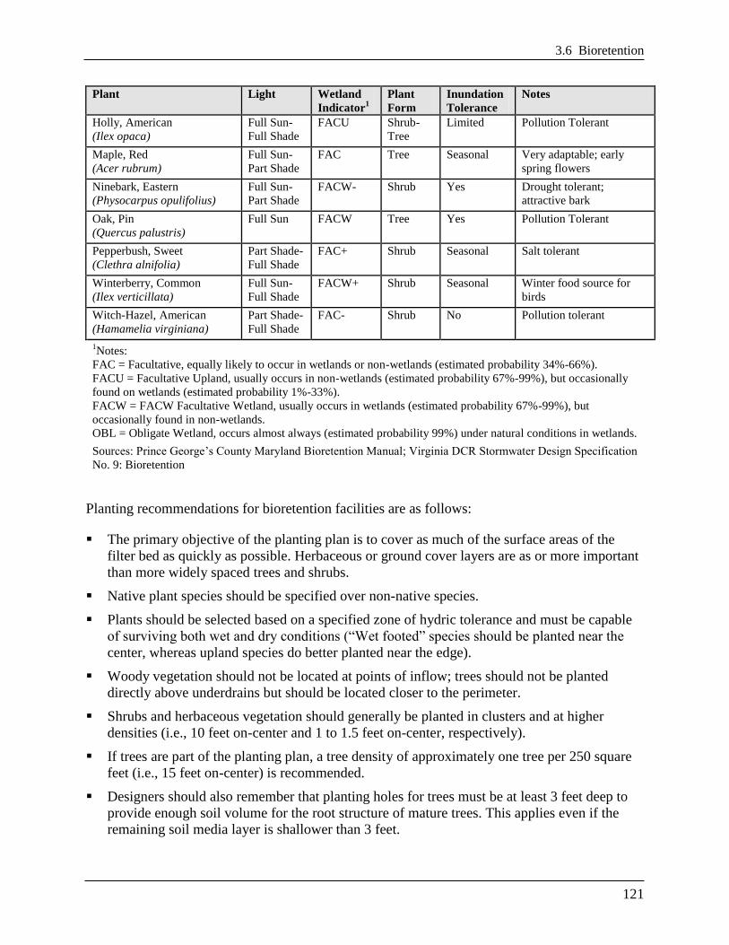
Table 3.24 Woody Plants Appropriate for Bioretention Areas in the District
Plant Light Wetland
Indicator1
Plant
Form
Inundation
Tolerance
Notes
Arrow-wood
(Viburnum dentatum)
Full Sun-
Part Shade
FAC Shrub Seasonal Salt tolerant
River Birch
(Betula nigra)
Full Sun-
Part Shade
FACW Tree Seasonal Attractive bark
Bayberry, Northern
(Myrica pennsylvanica)
Full Sun-
Part Shade
FAC Shrub Seasonal Salt tolerant
Black Gum
(Nyssa sylvatica)
Full Sun-
Part Shade
FACW+ Tree Seasonal Excellent fall color
Dwarf Azalea
(Rhododendron atlanticum)
Part Shade FAC Shrub Yes Long lived
Black-Haw
(Viburnum prunifolium)
Part Shade-
Full Shade
FACU+ Shrub Yes Edible Fruit
Choke Cherry
(Prunus virginiana)
Full Sun FACU+ Shrub Yes Tolerates some salt; can
be maintained as hedge
Cedar, Eastern Red
(Juniperus virginiana)
Full Sun FACU Tree No Pollution tolerant
Cotton-wood, Eastern
(Populus deltoides)
Full Sun FAC Tree Seasonal Pollutant tolerant; salt
tolerant
Silky Dogwood
(Cornus amomum)
Full Sun-
Part Shade
FACW Shrub Seasonal High wildlife value
Hackberry, Common
(Celtis occidentalis)
Full Sun-
Full Shade
FACU Tree Seasonal Pollution Tolerant
Hazelnut, American
(Corylus americana)
Part Shade FACU Shrub No Forms thickets; edible nut
Holly, Winterberry
(Ilex laevigata)
Full Sun-
Part Shade
OBL Shrub Yes Winter food source for
birds
3.6 Bioretention
121
Plant Light Wetland
Indicator1
Plant
Form
Inundation
Tolerance
Notes
Holly, American
(Ilex opaca)
Full Sun-
Full Shade
FACU Shrub-
Tree
Limited Pollution Tolerant
Maple, Red
(Acer rubrum)
Full Sun-
Part Shade
FAC Tree Seasonal Very adaptable; early
spring flowers
Ninebark, Eastern
(Physocarpus opulifolius)
Full Sun-
Part Shade
FACW- Shrub Yes Drought tolerant;
attractive bark
Oak, Pin
(Quercus palustris)
Full Sun FACW Tree Yes Pollution Tolerant
Pepperbush, Sweet
(Clethra alnifolia)
Part Shade-
Full Shade
FAC+ Shrub Seasonal Salt tolerant
Winterberry, Common
(Ilex verticillata)
Full Sun-
Full Shade
FACW+ Shrub Seasonal Winter food source for
birds
Witch-Hazel, American
(Hamamelia virginiana)
Part Shade-
Full Shade
FAC- Shrub No Pollution tolerant
1Notes:
FAC = Facultative, equally likely to occur in wetlands or non-wetlands (estimated probability 34%-66%).
FACU = Facultative Upland, usually occurs in non-wetlands (estimated probability 67%-99%), but occasionally
found on wetlands (estimated probability 1%-33%).
FACW = FACW Facultative Wetland, usually occurs in wetlands (estimated probability 67%-99%), but
occasionally found in non-wetlands.
OBL = Obligate Wetland, occurs almost always (estimated probability 99%) under natural conditions in wetlands.
Sources: Prince George’s County Maryland Bioretention Manual; Virginia DCR Stormwater Design Specification
No. 9: Bioretention
Planting recommendations for bioretention facilities are as follows:
The primary objective of the planting plan is to cover as much of the surface areas of the
filter bed as quickly as possible. Herbaceous or ground cover layers are as or more important
than more widely spaced trees and shrubs.
Native plant species should be specified over non-native species.
Plants should be selected based on a specified zone of hydric tolerance and must be capable
of surviving both wet and dry conditions (―Wet footed‖ species should be planted near the
center, whereas upland species do better planted near the edge).
Woody vegetation should not be located at points of inflow; trees should not be planted
directly above underdrains but should be located closer to the perimeter.
Shrubs and herbaceous vegetation should generally be planted in clusters and at higher
densities (i.e., 10 feet on-center and 1 to 1.5 feet on-center, respectively).
If trees are part of the planting plan, a tree density of approximately one tree per 250 square
feet (i.e., 15 feet on-center) is recommended.
Designers should also remember that planting holes for trees must be at least 3 feet deep to
provide enough soil volume for the root structure of mature trees. This applies even if the
remaining soil media layer is shallower than 3 feet.

Chapter 3 Stormwater Best Management Practices (BMPs)
122
Tree species should be those that are known to survive well in the compacted soils and the
polluted air and water of an urban landscape.
If trees are used, plant shade-tolerant ground covers within the drip line.
If the bioretention area is to be used for snow storage or is to accept snowmelt runoff, it
should be planted with salt-tolerant, herbaceous perennials.
3.6.6 Bioretention Construction Sequence
Soil Erosion and Sediment Controls. The following soil erosion and sediment control
guidelines must be followed during construction:
All Bioretention areas must be fully protected by silt fence or construction fencing.
Bioretention areas intended to infiltrate runoff must remain outside the limit of disturbance
during construction to prevent soil compaction by heavy equipment and loss of design
infiltration rate.
Where it is infeasible keep the proposed bioretention areas outside of the limits of
disturbance, there are several possible outcomes for the impacted area. If excavation in
the proposed bioretention area can be restricted then the remediation can be achieved
with deep tilling practices. This is only possible if in-situ soils are not disturbed any
deeper than 2 feet above the final design elevation of the bottom of the bioretention. In
this case, when heavy equipment activity has ceased, the area is excavated to grade, and
the impacted area must be tilled to a depth of 12 inches below the bottom of the
bioretention.
Alternatively, if it is infeasible to keep the proposed permeable pavement areas outside of
the limits of disturbance, and excavation of the area cannot be restricted, then infiltration
tests will be required prior to installation of the bioretention to ensure that the design
infiltration rate is still present. If tests reveal the loss of design infiltration rates then deep
tilling practices may be used in an effort to restore those rates. In this case further testing
must be done to establish design rates exist before the permeable pavement can be
installed.
Finally, if it is infeasible to keep the proposed bioretention areas outside of the limits of
disturbance, and excavation of the area cannot be restricted, and infiltration tests reveal
design rates cannot be restored, then a resubmission of the SWMP will be required.
Bioretention areas must be clearly marked on all construction documents and grading plans.
Large bioretention applications may be used as small sediment traps or basins during
construction. However, these must be accompanied by notes and graphic details on the soil
erosion and sediment control plan specifying that (1) the maximum excavation depth of the
trap or basin at the construction stage must be at least 1 foot higher than the post-construction
(final) invert (bottom of the facility), and (2) the facility must contain an underdrain. The
plan must also show the proper procedures for converting the temporary sediment control
practice to a permanent bioretention BMP, including dewatering, cleanout, and stabilization.
3.6 Bioretention
123
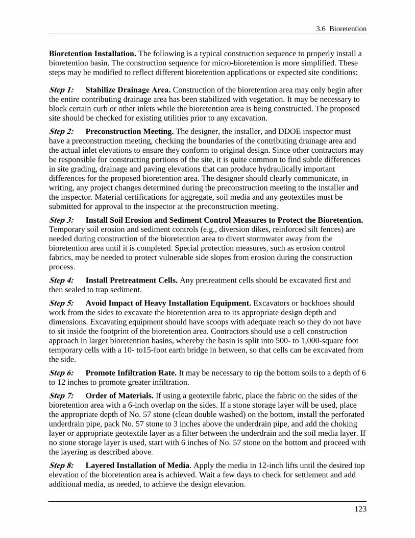
Bioretention Installation. The following is a typical construction sequence to properly install a
bioretention basin. The construction sequence for micro-bioretention is more simplified. These
steps may be modified to reflect different bioretention applications or expected site conditions:
Step 1: Stabilize Drainage Area. Construction of the bioretention area may only begin after
the entire contributing drainage area has been stabilized with vegetation. It may be necessary to
block certain curb or other inlets while the bioretention area is being constructed. The proposed
site should be checked for existing utilities prior to any excavation.
Step 2: Preconstruction Meeting. The designer, the installer, and DDOE inspector must
have a preconstruction meeting, checking the boundaries of the contributing drainage area and
the actual inlet elevations to ensure they conform to original design. Since other contractors may
be responsible for constructing portions of the site, it is quite common to find subtle differences
in site grading, drainage and paving elevations that can produce hydraulically important
differences for the proposed bioretention area. The designer should clearly communicate, in
writing, any project changes determined during the preconstruction meeting to the installer and
the inspector. Material certifications for aggregate, soil media and any geotextiles must be
submitted for approval to the inspector at the preconstruction meeting.
Step 3: Install Soil Erosion and Sediment Control Measures to Protect the Bioretention. Temporary soil erosion and sediment controls (e.g., diversion dikes, reinforced silt fences) are
needed during construction of the bioretention area to divert stormwater away from the
bioretention area until it is completed. Special protection measures, such as erosion control
fabrics, may be needed to protect vulnerable side slopes from erosion during the construction
process.
Step 4: Install Pretreatment Cells. Any pretreatment cells should be excavated first and
then sealed to trap sediment.
Step 5: Avoid Impact of Heavy Installation Equipment. Excavators or backhoes should
work from the sides to excavate the bioretention area to its appropriate design depth and
dimensions. Excavating equipment should have scoops with adequate reach so they do not have
to sit inside the footprint of the bioretention area. Contractors should use a cell construction
approach in larger bioretention basins, whereby the basin is split into 500- to 1,000-square foot
temporary cells with a 10- to15-foot earth bridge in between, so that cells can be excavated from
the side.
Step 6: Promote Infiltration Rate. It may be necessary to rip the bottom soils to a depth of 6
to 12 inches to promote greater infiltration.
Step 7: Order of Materials. If using a geotextile fabric, place the fabric on the sides of the
bioretention area with a 6-inch overlap on the sides. If a stone storage layer will be used, place
the appropriate depth of No. 57 stone (clean double washed) on the bottom, install the perforated
underdrain pipe, pack No. 57 stone to 3 inches above the underdrain pipe, and add the choking
layer or appropriate geotextile layer as a filter between the underdrain and the soil media layer. If
no stone storage layer is used, start with 6 inches of No. 57 stone on the bottom and proceed with
the layering as described above.
Step 8: Layered Installation of Media. Apply the media in 12-inch lifts until the desired top
elevation of the bioretention area is achieved. Wait a few days to check for settlement and add
additional media, as needed, to achieve the design elevation.
Chapter 3 Stormwater Best Management Practices (BMPs)
124
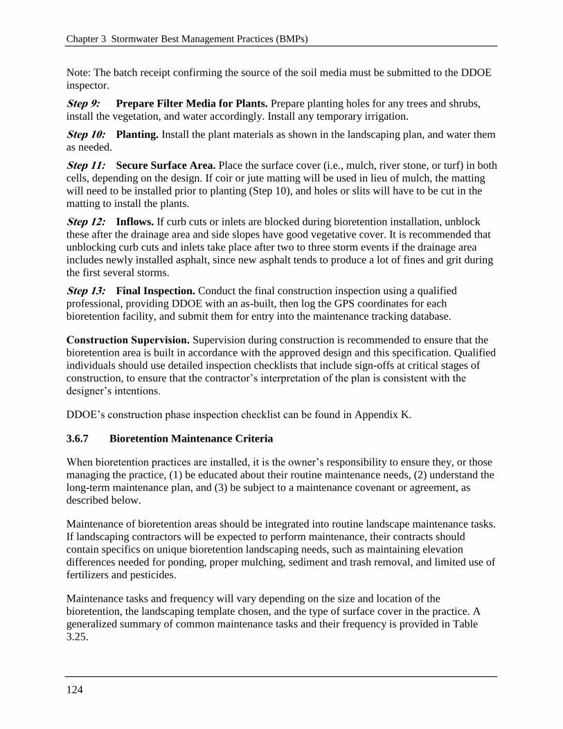
Note: The batch receipt confirming the source of the soil media must be submitted to the DDOE
inspector.
Step 9: Prepare Filter Media for Plants. Prepare planting holes for any trees and shrubs,
install the vegetation, and water accordingly. Install any temporary irrigation.
Step 10: Planting. Install the plant materials as shown in the landscaping plan, and water them
as needed.
Step 11: Secure Surface Area. Place the surface cover (i.e., mulch, river stone, or turf) in both
cells, depending on the design. If coir or jute matting will be used in lieu of mulch, the matting
will need to be installed prior to planting (Step 10), and holes or slits will have to be cut in the
matting to install the plants.
Step 12: Inflows. If curb cuts or inlets are blocked during bioretention installation, unblock
these after the drainage area and side slopes have good vegetative cover. It is recommended that
unblocking curb cuts and inlets take place after two to three storm events if the drainage area
includes newly installed asphalt, since new asphalt tends to produce a lot of fines and grit during
the first several storms.
Step 13: Final Inspection. Conduct the final construction inspection using a qualified
professional, providing DDOE with an as-built, then log the GPS coordinates for each
bioretention facility, and submit them for entry into the maintenance tracking database.
Construction Supervision. Supervision during construction is recommended to ensure that the
bioretention area is built in accordance with the approved design and this specification. Qualified
individuals should use detailed inspection checklists that include sign-offs at critical stages of
construction, to ensure that the contractor’s interpretation of the plan is consistent with the
designer’s intentions.
DDOE’s construction phase inspection checklist can be found in Appendix K.
3.6.7 Bioretention Maintenance Criteria
When bioretention practices are installed, it is the owner’s responsibility to ensure they, or those
managing the practice, (1) be educated about their routine maintenance needs, (2) understand the
long-term maintenance plan, and (3) be subject to a maintenance covenant or agreement, as
described below.
Maintenance of bioretention areas should be integrated into routine landscape maintenance tasks.
If landscaping contractors will be expected to perform maintenance, their contracts should
contain specifics on unique bioretention landscaping needs, such as maintaining elevation
differences needed for ponding, proper mulching, sediment and trash removal, and limited use of
fertilizers and pesticides.
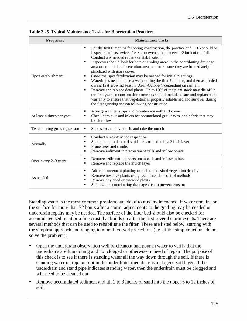
Maintenance tasks and frequency will vary depending on the size and location of the
bioretention, the landscaping template chosen, and the type of surface cover in the practice. A
generalized summary of common maintenance tasks and their frequency is provided in Table
3.25.
3.6 Bioretention
125
Table 3.25 Typical Maintenance Tasks for Bioretention Practices
Frequency Maintenance Tasks
Upon establishment
For the first 6 months following construction, the practice and CDA should be
inspected at least twice after storm events that exceed 1/2 inch of rainfall.
Conduct any needed repairs or stabilization.
Inspectors should look for bare or eroding areas in the contributing drainage
area or around the bioretention area, and make sure they are immediately
stabilized with grass cover.
One-time, spot fertilization may be needed for initial plantings.
Watering is needed once a week during the first 2 months, and then as needed
during first growing season (April-October), depending on rainfall.
Remove and replace dead plants. Up to 10% of the plant stock may die off in
the first year, so construction contracts should include a care and replacement
warranty to ensure that vegetation is properly established and survives during
the first growing season following construction.
At least 4 times per year
Mow grass filter strips and bioretention with turf cover
Check curb cuts and inlets for accumulated grit, leaves, and debris that may
block inflow
Twice during growing season Spot weed, remove trash, and rake the mulch
Annually
Conduct a maintenance inspection
Supplement mulch in devoid areas to maintain a 3 inch layer
Prune trees and shrubs
Remove sediment in pretreatment cells and inflow points
Once every 2–3 years Remove sediment in pretreatment cells and inflow points
Remove and replace the mulch layer
As needed
Add reinforcement planting to maintain desired vegetation density
Remove invasive plants using recommended control methods
Remove any dead or diseased plants
Stabilize the contributing drainage area to prevent erosion
Standing water is the most common problem outside of routine maintenance. If water remains on
the surface for more than 72 hours after a storm, adjustments to the grading may be needed or
underdrain repairs may be needed. The surface of the filter bed should also be checked for
accumulated sediment or a fine crust that builds up after the first several storm events. There are
several methods that can be used to rehabilitate the filter. These are listed below, starting with
the simplest approach and ranging to more involved procedures (i.e., if the simpler actions do not
solve the problem):
Open the underdrain observation well or cleanout and pour in water to verify that the
underdrains are functioning and not clogged or otherwise in need of repair. The purpose of
this check is to see if there is standing water all the way down through the soil. If there is
standing water on top, but not in the underdrain, then there is a clogged soil layer. If the
underdrain and stand pipe indicates standing water, then the underdrain must be clogged and
will need to be cleaned out.
Remove accumulated sediment and till 2 to 3 inches of sand into the upper 6 to 12 inches of
soil.
Chapter 3 Stormwater Best Management Practices (BMPs)
126
Install sand wicks from 3 inches below the surface to the underdrain layer. This reduces the
average concentration of fines in the media bed and promotes quicker drawdown times. Sand
wicks can be installed by excavating or auguring (i.e., using a tree auger or similar tool)
down to the top of the underdrain layer to create vertical columns which are then filled with a
clean open-graded coarse sand material (e.g., ASTM C-33 concrete sand or similar approved
sand mix for bioretention media). A sufficient number of wick drains of sufficient dimension
should be installed to meet the design dewatering time for the facility.
Remove and replace some or all of the soil media.
Maintenance Inspections. It is recommended that a qualified professional conduct a spring
maintenance inspection and cleanup at each bioretention area. Maintenance inspections should
include information about the inlets, the actual bioretention facility (sediment buildup, outlet
conditions, etc.), and the state of vegetation (water stressed, dead, etc.) and are intended to
highlight any issues that need or may need attention to maintain stormwater management
functionality.
DDOE’s maintenance inspection checklists for bioretention areas and the Maintenance Service
Completion Inspection form can be found in Appendix L.
Declaration of Covenants. A declaration of covenants that includes all maintenance
responsibilities to ensure the continued stormwater performance for the BMP is required. The
declaration of covenants specifies the property owner’s primary maintenance responsibilities,
and authorizes DDOE staff to access the property for inspection or corrective action in the event
the proper maintenance is not performed. The declaration of covenants is attached to the deed of
the property. A template form is provided at the end of Chapter 5 (see Figure 5.4), although
variations will exist for scenarios where stormwater crosses property lines. The covenant is
between the property and the Government of the District of Columbia. It is submitted through the
Office of the Attorney General. All SWMPs have a maintenance agreement stamp that must be
signed for a building permit to proceed. A maintenance schedule must appear on the SWMP.
Additionally, a maintenance schedule is required in Exhibit C of the declaration of covenants.
Covenants are not required on government properties, but maintenance responsibilities must be
defined through a partnership agreement or a memorandum of understanding.
Waste Material. Waste material from the repair, maintenance, or removal of a BMP or land
cover shall be removed and disposed of in compliance with applicable federal and District law.
3.6.8 Bioretention Stormwater Compliance Calculations
Bioretention performance varies depending on the design configuration of the system.
Enhanced Designs. These designs are bioretention applications with no underdrain or at least 24
inches of filter media and an infiltration sump. Enhanced designs receive 100 percent retention
value for the amount of storage volume (Sv) provided by the practice (Table 3.26), and,
therefore, are not considered an accepted total suspended solids (TSS) treatment practice.
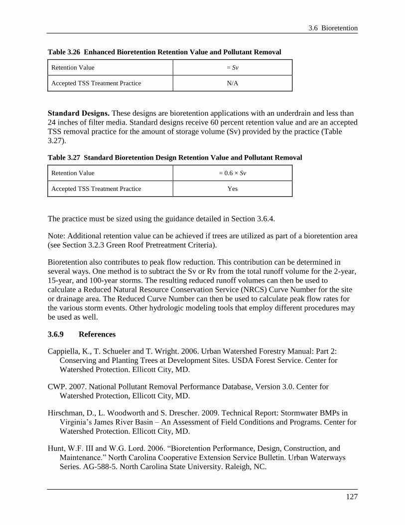
3.6 Bioretention
127
Table 3.26 Enhanced Bioretention Retention Value and Pollutant Removal
Retention Value = Sv
Accepted TSS Treatment Practice N/A
Standard Designs. These designs are bioretention applications with an underdrain and less than
24 inches of filter media. Standard designs receive 60 percent retention value and are an accepted
TSS removal practice for the amount of storage volume (Sv) provided by the practice (Table
3.27).
Table 3.27 Standard Bioretention Design Retention Value and Pollutant Removal
Retention Value = 0.6 × Sv
Accepted TSS Treatment Practice Yes
The practice must be sized using the guidance detailed in Section 3.6.4.
Note: Additional retention value can be achieved if trees are utilized as part of a bioretention area
(see Section 3.2.3 Green Roof Pretreatment Criteria).
Bioretention also contributes to peak flow reduction. This contribution can be determined in
several ways. One method is to subtract the Sv or Rv from the total runoff volume for the 2-year,
15-year, and 100-year storms. The resulting reduced runoff volumes can then be used to
calculate a Reduced Natural Resource Conservation Service (NRCS) Curve Number for the site
or drainage area. The Reduced Curve Number can then be used to calculate peak flow rates for
the various storm events. Other hydrologic modeling tools that employ different procedures may
be used as well.
3.6.9 References
Cappiella, K., T. Schueler and T. Wright. 2006. Urban Watershed Forestry Manual: Part 2:
Conserving and Planting Trees at Development Sites. USDA Forest Service. Center for
Watershed Protection. Ellicott City, MD.
CWP. 2007. National Pollutant Removal Performance Database, Version 3.0. Center for
Watershed Protection, Ellicott City, MD.
Hirschman, D., L. Woodworth and S. Drescher. 2009. Technical Report: Stormwater BMPs in
Virginia’s James River Basin – An Assessment of Field Conditions and Programs. Center for
Watershed Protection. Ellicott City, MD.
Hunt, W.F. III and W.G. Lord. 2006. ―Bioretention Performance, Design, Construction, and
Maintenance.‖ North Carolina Cooperative Extension Service Bulletin. Urban Waterways
Series. AG-588-5. North Carolina State University. Raleigh, NC.
Chapter 3 Stormwater Best Management Practices (BMPs)
128
Maryland Department of the Environment. 2001. Maryland Stormwater Design Manual.
http://www.mde.state.md.us/programs/Water/StormwaterManagementProgram/MarylandStor
mwaterDesignManual/Pages/Programs/WaterPrograms/SedimentandStormwater/stormwater
_design/index.aspx
Prince George’s Co., MD. 2007. Bioretention Manual. Available online at:
http://www.princegeorgescountymd.gov/Government/AgencyIndex/DER/ESG/Bioretention/
pdf/Bioretention%20Manual_2009%20Version.pdf
Saxton, K.E., W.J. Rawls, J.S. Romberger, and R.I. Papendick. 1986. ―Estimating generalized
soil-water characteristics from texture.‖ Soil Sci. Soc. Am. J. 50(4):1031-1036.Schueler, T.
2008. Technical Support for the Baywide Runoff Reduction Method. Chesapeake
Stormwater Network. Baltimore, MD. www.chesapeakestormwater.net
Smith, R.A. and Hunt, W.F. III. 1999. ―Pollutant Removal in Bioretention Cells with Grass
Cover‖
Smith, R. A., and Hunt, W.F. III. 2007. ―Pollutant removal in bioretention cells with grass
cover.‖ Pp. 1-11 In: Proceedings of the World Environmental and Water Resources Congress
2007.
Sumner, M. E. and W. P. Miller. 1996. Cation Exchange Capacity and Exchange Coefficients.
Methods of Soil Analysis, Part 3 – Chemical Methods: 1201-1229
Virginia DCR Stormwater Design Specification No. 9: Bioretention Version 1.8. 2010.
Wisconsin Department of Natural Resources. Storm Water Post-Construction Technical
Standards. http://dnr.wi.gov/topic/stormwater/standards/postconst_standards.html