35010041 - User manual, RUSH Club Smoke Dual€¦ · almost invisible blue flame. ... If eye...
32
user manual P/N 35010041-A READ AND SAVE THESE INSTRUCTIONS
Transcript of 35010041 - User manual, RUSH Club Smoke Dual€¦ · almost invisible blue flame. ... If eye...
user manual
P/N 35010041-A
READ AND SAVE THESE INSTRUCTIONS

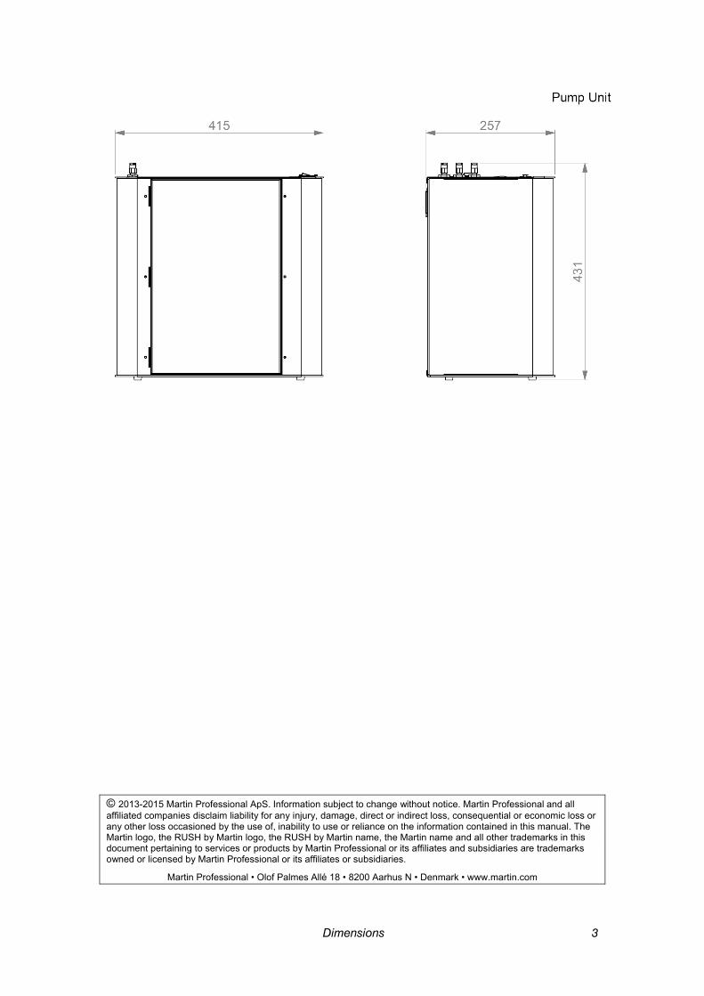
2 Dimensions
Dimensions All dimensions are in millimeters
Dimensions 3
© 2013-2015 Martin Professional ApS. Information subject to change without notice. Martin Professional and all affiliated companies disclaim liability for any injury, damage, direct or indirect loss, consequential or economic loss or any other loss occasioned by the use of, inability to use or reliance on the information contained in this manual. The Martin logo, the RUSH by Martin logo, the RUSH by Martin name, the Martin name and all other trademarks in this document pertaining to services or products by Martin Professional or its affiliates and subsidiaries are trademarks owned or licensed by Martin Professional or its affiliates or subsidiaries.
Martin Professional • Olof Palmes Allé 18 • 8200 Aarhus N • Denmark • www.martin.com

4 Contents
Contents Dimensions ................................................................................................................................ 2
Contents ..................................................................................................................................... 4
Safety information ...................................................................................................................... 5
Product overview ....................................................................................................................... 8 Product description ................................................................................................................ 8 Features at a glance ............................................................................................................... 8 Product details ....................................................................................................................... 9
Quick Start ............................................................................................................................... 12 Setting up ............................................................................................................................. 12 Making fog and haze ............................................................................................................ 12
Installation and setting up ........................................................................................................ 13 Location ............................................................................................................................... 13 AC power.............................................................................................................................. 13 Setting up ............................................................................................................................. 14 Final checks ......................................................................................................................... 16 Turning on the power ........................................................................................................... 16
Control settings ........................................................................................................................ 17 Overview .............................................................................................................................. 17 Setting Fog Run modes ........................................................................................................ 17 Setting output density for Fog heads ................................................................................... 17 Setting Haze Run modes ...................................................................................................... 17 Setting output density for Haze heads .................................................................................. 18 Setting the Timer .................................................................................................................. 18 Setting the DMX base address ............................................................................................. 18 Setting the master-slave link mode ...................................................................................... 18 Priming the system after fluid out ......................................................................................... 18 Priming system with Quick access buttons .......................................................................... 19 Resetting options to factory settings .................................................................................... 19
Remote control ........................................................................................................................ 21 Overview .............................................................................................................................. 21 Functions .............................................................................................................................. 21 Connection ........................................................................................................................... 21
DMX control ............................................................................................................................. 23 Overview .............................................................................................................................. 23 Connection ........................................................................................................................... 23 DMX functions ...................................................................................................................... 23
Fog fluid types ......................................................................................................................... 25
Basic service ........................................................................................................................... 26 Cleaning ............................................................................................................................... 26 Fuse replacement................................................................................................................. 26
Troubleshooting ....................................................................................................................... 27
Status messages ...................................................................................................................... 28 Resetting the system after fluid out ...................................................................................... 28
Specifications .......................................................................................................................... 29
Safety information 5
Safety information
Read the safety precautions in this manual befor installing, operating or servicing this product.
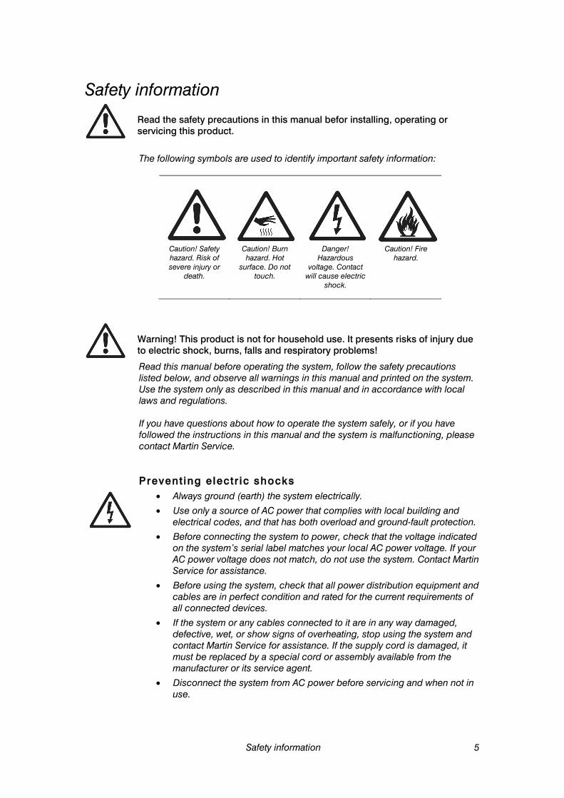
The following symbols are used to identify important safety information:
Caution! Safety hazard. Risk of severe injury or
death.
Caution! Burn hazard. Hot
surface. Do not touch.
Danger! Hazardous
voltage. Contact will cause electric
shock.
Caution! Fire hazard.
Warning! This product is not for household use. It presents risks of injury due to electric shock, burns, falls and respiratory problems!
Read this manual before operating the system, follow the safety precautions listed below, and observe all warnings in this manual and printed on the system. Use the system only as described in this manual and in accordance with local laws and regulations. If you have questions about how to operate the system safely, or if you have followed the instructions in this manual and the system is malfunctioning, please contact Martin Service.
Prevent ing electr ic shocks • Always ground (earth) the system electrically.
• Use only a source of AC power that complies with local building and electrical codes, and that has both overload and ground-fault protection.
• Before connecting the system to power, check that the voltage indicated on the system’s serial label matches your local AC power voltage. If your AC power voltage does not match, do not use the system. Contact Martin Service for assistance.
• Before using the system, check that all power distribution equipment and cables are in perfect condition and rated for the current requirements of all connected devices.
• If the system or any cables connected to it are in any way damaged, defective, wet, or show signs of overheating, stop using the system and contact Martin Service for assistance. If the supply cord is damaged, it must be replaced by a special cord or assembly available from the manufacturer or its service agent.
• Disconnect the system from AC power before servicing and when not in use.

6 Safety information
• This system is not waterproof and should not be exposed to wet outdoor conditions. Do not immerse in water or any other liquid. Do not expose to high-pressure water jets.
• Do not spill fluid over or inside the system. If fluid is spilled, disconnect AC power and clean with a damp cloth. If fluid is spilled onto electronic parts, take the system out of service and contact Martin for advice.
• Do not remove the covers or attempt to repair a faulty system. Refer any service not described in this manual to Martin.
• Do not operate the system if any parts are damaged, defective or missing.
• Moisture and electricity do not mix. Do not aim fog output at electrical connections or devices.
Prevent ing burns and f i re • The fog produced by the system is hot enough to cause burns when it
leaves the nozzle, and very hot droplets of fluid escape occasionally. Keep people and objects at least 60cm (24 inches) away from the fog output nozzle.
• Do not touch the fog output nozzle during or after use – it becomes extremely hot and remains hot for several hours after the system has been shut down.
• Fog output contains glycol, a flammable alcohol that burns with an almost invisible blue flame. Do not point fog output at sources of ignition such as open flames or pyrotechnic effects.
• Do not attempt to bypass thermostatic switches, fluid sensors or fuses.
• Replace fuses only with ones of the type and rating specified in this manual for the system.
• Provide a minimum free space of 100mm (4 inches) around the system.
• Provide a minimum free space of 500mm (20 inches) around fans and air vents and ensure free and unobstructed air flow to and around the system.
• Keep the system at least 60cm (24 inches) away from combustible and heat-sensitive materials.
• Do not operate the system if the ambient temperature (Ta) is below 5° C (41° F) or above 40° C (104° F).
• Do not operate the system if the relative air humidity exceeds 80%.
Prevent ing in jur ies • Fasten the system securely to a fixed surface or structure when in use.
The system is not portable when installed.
• Ensure that any supporting structure and/or hardware used can hold at least 10 times the weight of all the devices they support.
• If suspending from a rigging structure, fasten the system to a rigging clamp. Do not use safety cables as the primary means of support.
• If the system is installed in a location where it may cause injury or damage if it falls, install as directed in this manual a secondary attachment such as a safety cable that will hold the system if a primary attachment fails. The secondary attachment must be approved by an official body such as TÜV as a safety attachment for the weight that it secures, must comply with EN 60598-2-17 Section 17.6.6 and must be capable of bearing a
Safety information 7
static suspended load that is ten times the weight of the system and all installed accessories.
• Check that all external covers and rigging hardware are securely fastened.
• Block access below the work area and work from a stable platform whenever installing, servicing or moving the system.
• Do not operate the system with missing or damaged covers or shields.
• In the event of an operating problem, stop using the system immediately and disconnect it from power. Do not attempt to use a system that is obviously damaged.
• Do not modify the system in any way not described in this manual or install other than genuine RUSH by Martin™ parts.
• Refer any service operation not described in this manual to a qualified technician.
• Fog output can cause condensation. Do not point the output at smooth floors. Floors and surfaces may become slippery. Check these frequently and wipe dry as necessary to avoid any danger of slipping.
• Ensure at least 2 m visibility in areas where fog is being produced.
• Fog fluid contains food-grade glycols in solution but may present health risks if swallowed. Do not drink it. Store it securely. If eye contact occurs, rinse with water. If fluid is swallowed, give water and obtain medical advice.
• This appliance is not intended for use by persons (including children) with reduced physical sensory or mental capabilities, or lack of experience and knowledge, unless they have been given supervision or instruction concerning use of the appliance by a person responsible for their safety. Children should be supervised to ensure that they do not play with the appliance.
Prevent ing breathing problems • A system can operate safely only with the fog fluid it is designed for. Use
the system only with fluids specified under “Fog fluid options” on page 25 or you may cause the release of toxic gases, presenting a severe health hazard. You will also probably damage the system.
• Do not create dense fog in confined or poorly ventilated areas.
• Do not expose people with health problems (including allergic and/or respiratory conditions such as asthma) to fog output.
• Do not point fog output directly at a person’s face or at face height. For the latest user documentation and other information for this and all Martin™ products, please visit the Martin website at http://www.martin.com If you have any questions about how to install, operate or service the fixture safely, please contact your Martin™ distributor (see www.martin.com/distributors for details) or call the Martin™ 24-hour service hotline on +45 8740 0000, or in the USA on 1-888-tech-180.
8 Product overview
Product overview
Product descr ip t ion The RUSH Club Smoke Dual™ is a top of the range atmosphere system from Martin Professional featuring multiple remote fog or haze heads with a base pump/fluid unit. Its remote heads allow the base unit to be conveniently located for fluid refill while the heads can be positioned in the ideal location for even fogging or hazing of the venue. Designed using the latest fog system technology, the RUSH Club Smoke Dual™ is capable of generating a variable level of fog or haze from up to 6 heads controlled in pairs, which are connected using a simple push together fluid line and a single control cable. Congratulations on your purchase of the RUSH Club Smoke Dual™ from Martin. Details of the full range of Martin products are available on our website at www.martin.com.
Features a t a g lance • 1-6 Fog or Haze heads per system
• Flying/hanging brackets as standard
• Continuous output
• Water-based fluid with long hang time
• Low noise
• Lightweight
• Variable output control for each head pair using DMX
• 10 liter (2.64 US gal.) fluid capacity
• “Out of Fluid” sensing using pressure sensor
• Valved output connectors on pump unit
• On-board DMX 3-pin and 5-pin
• User-friendly on-board control panel
• Optional external fluid connection and Digital Remote Control
Use only Martin RUSH Club Smoke Dual Fluid™. Use of other fluid will void warranty.

Product overview 9
Control link output to next head
Control input from pump unit
Mains power switch
Mains inlet cable
Fluid pipe connection
Heat (red) and Ready (green) indicators
Product deta i ls Fog Head
Fog output nozzle
WARNING!High temperature vapour and surfaces
10 Product overview
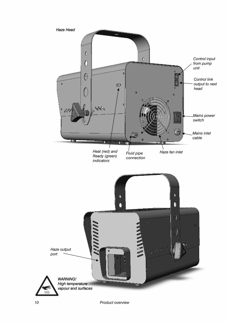
Control link output to next head
Control input from pump unit
Mains power switch
Mains inlet cable
Fluid pipe connection
Heat (red) and Ready (green) indicators
Haze fan inlet
Haze Head
Haze output port
WARNING! High temperature vapour and surfaces

Product overview 11
Base pump unit
Digital control panel
Power inletconnector
Main powerswitch
Digital remote plug
AVR program upload socket and status LEDs
5 pin DMX input and link
3 pin DMX input and link
Hinged door to fluid tank compartment
Control connections to heads
Fluid outputs to heads
12 Quick Start
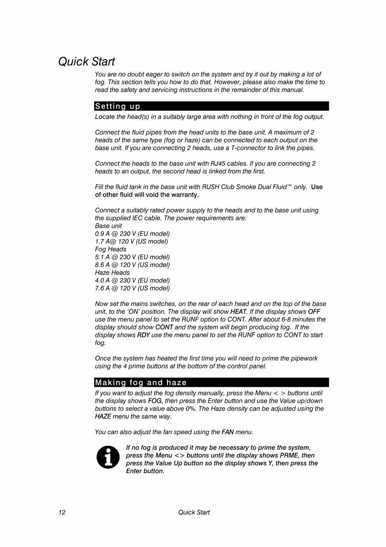
Quick Start You are no doubt eager to switch on the system and try it out by making a lot of fog. This section tells you how to do that. However, please also make the time to read the safety and servicing instructions in the remainder of this manual.
Set t ing up Locate the head(s) in a suitably large area with nothing in front of the fog output. Connect the fluid pipes from the head units to the base unit. A maximum of 2 heads of the same type (fog or haze) can be connected to each output on the base unit. If you are connecting 2 heads, use a T-connector to link the pipes. Connect the heads to the base unit with RJ45 cables. If you are connecting 2 heads to an output, the second head is linked from the first. Fill the fluid tank in the base unit with RUSH Club Smoke Dual Fluid™ only. Use of other fluid will void the warranty. Connect a suitably rated power supply to the heads and to the base unit using the supplied IEC cable. The power requirements are: Base unit 0.9 A @ 230 V (EU model) 1.7 A@ 120 V (US model) Fog Heads 5.1 A @ 230 V (EU model) 8.6 A @ 120 V (US model) Haze Heads 4.0 A @ 230 V (EU model) 7.6 A @ 120 V (US model)
Now set the mains switches, on the rear of each head and on the top of the base unit, to the ‘ON’ position. The display will show HEAT. If the display shows OFF use the menu panel to set the RUNF option to CONT. After about 6-8 minutes the display should show CONT and the system will begin producing fog. If the display shows RDY use the menu panel to set the RUNF option to CONT to start fog. Once the system has heated the first time you will need to prime the pipework using the 4 prime buttons at the bottom of the control panel.
Making fog and haze If you want to adjust the fog density manually, press the Menu < > buttons until the display shows FOG, then press the Enter button and use the Value up/down buttons to select a value above 0%. The Haze density can be adjusted using the HAZE menu the same way. You can also adjust the fan speed using the FAN menu.
If no fog is produced it may be necessary to prime the system, press the Menu <> buttons until the display shows PRME, then press the Value Up button so the display shows Y, then press the Enter button.
Installation and setting up 13
Installation and setting up
DANGER! DO NOT operate the system until you have read and observed all the precautions listed under “Safety information” on page 5.
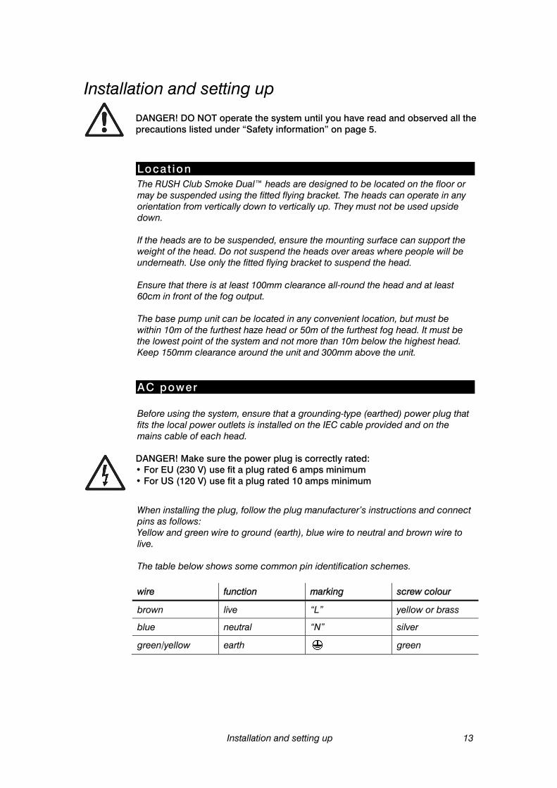
Locat ion The RUSH Club Smoke Dual™ heads are designed to be located on the floor or may be suspended using the fitted flying bracket. The heads can operate in any orientation from vertically down to vertically up. They must not be used upside down. If the heads are to be suspended, ensure the mounting surface can support the weight of the head. Do not suspend the heads over areas where people will be underneath. Use only the fitted flying bracket to suspend the head. Ensure that there is at least 100mm clearance all-round the head and at least 60cm in front of the fog output. The base pump unit can be located in any convenient location, but must be within 10m of the furthest haze head or 50m of the furthest fog head. It must be the lowest point of the system and not more than 10m below the highest head. Keep 150mm clearance around the unit and 300mm above the unit.
AC power Before using the system, ensure that a grounding-type (earthed) power plug that fits the local power outlets is installed on the IEC cable provided and on the mains cable of each head.
DANGER! Make sure the power plug is correctly rated:• For EU (230 V) use fit a plug rated 6 amps minimum • For US (120 V) use fit a plug rated 10 amps minimum
When installing the plug, follow the plug manufacturer’s instructions and connect pins as follows: Yellow and green wire to ground (earth), blue wire to neutral and brown wire to live. The table below shows some common pin identification schemes. wire function marking screw colour
brown live “L” yellow or brass
blue neutral “N” silver
green/yellow earth green

14 Installation and setting up
Before connecting the system to power, verify that the AC supply is adequately dimensioned for the current draw of the system. Base unit 0.9 A @ 230 V (EU model) 1.7 A@ 120 V (US model) Fog Heads 5.1 A @ 230 V (EU model) 8.6 A @ 120 V (US model) Haze Heads 4.0 A @ 230 V (EU model) 7.6 A @ 120 V (US model) Check that the local AC voltage is appropriate, as indicated on the system’s serial number label. If your AC voltage is outside the appropriate range, do not use the system. Contact Martin Service for assistance.
Set t ing up Fill the fluid tank only with Martin RUSH Club Smoke Dual Fluid™ (see page 25). Up to two heads of the same type (fog or haze) may be connected to each fluid output of the pump unit. Push the fluid tubing into the connections on the head and the pump unit and secure on the heads using the locking screw. If two heads are being connected to an output, a T-connector must be fitted in the fluid tubing.
It is recommended that if you are using Haze heads you should connect them to channel 1
Connect the RJ45 control connection on the heads to the pump unit. If two heads are being connected to a channel, use the RJ45 link output on the first head to connect the second head. The RJ45 connectors are linked together internally and either can be used as input or link. Connection of single head

Installation and setting up 15
Connection of two heads on one channel
Connection of fully loaded system
T-connector
Haze heads on channel 1
T-connector

16 Installation and setting up
If DMX control is being used, connect the base unit to the DMX line (see page 18). If the Digital Remote is being used (optional accessory), connect the remote to the Remote socket (see page 9).
Final checks Before applying power to the system, verify the following:
• the system is safely located or installed and meets the location requirements stated on page 13
• the operator is familiar with, and able to comply with, the requirements for safe operation listed on page 5.
• the fluid is one of the genuine Martin fluids listed under “Fluid options” on page 25.
• the system is electrically grounded (earthed)
• the AC power distribution circuits and lines are adequately rated for the current load
Turning on the power Ensure the power switch on each head is turned on. Turn on the main power switch on the base unit located next to the power inlet. The display will show HEAT. If the display shows OFF, go to the RUNF menu on the digital control panel and set the option to CONT. The system will remember its state from when it was turned off last time, so it will only power up in OFF mode if you have previously disabled the heaters. After about 6-8 minutes if no DMX is connected the display should show CONT and the system will begin producing fog. If the display shows RDY go to the RUNF menu and set the option to CONT to start fog. If DMX is connected the display will show DMX when the system is ready. Each head has a red and green light on the side to indicate heating status: RED: Heating GREEN: Ready Once the Ready light has come on, the head will continue to heat for a time, and the heater will cycle on and off to maintain the temperature.
The first time you run the system after connecting fluid pipes you will need to prime the system. See section “Priming system with Quick access buttons” on page 19.
Control settings 17
Control settings
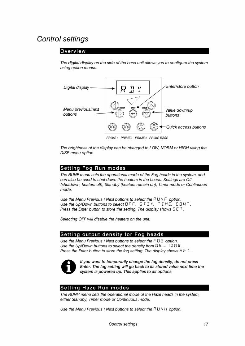
Overv iew The digital display on the side of the base unit allows you to configure the system using option menus.
The brightness of the display can be changed to LOW, NORM or HIGH using the DISP menu option.
Set t ing Fog Run modes The RUNF menu sets the operational mode of the Fog heads in the system, and can also be used to shut down the heaters in the heads. Settings are Off (shutdown, heaters off), Standby (heaters remain on), Timer mode or Continuous mode. Use the Menu Previous / Next buttons to select the option. Use the Up/Down buttons to select . Press the Enter button to store the setting. The display shows . Selecting OFF will disable the heaters on the unit.
Set t ing output densi ty fo r Fog heads Use the Menu Previous / Next buttons to select the option. Use the Up/Down buttons to select the density from – . Press the Enter button to store the fog setting. The display shows .
If you want to temporarily change the fog density, do not press Enter. The fog setting will go back to its stored value next time the system is powered up. This applies to all options.
Set t ing Haze Run modes The RUNH menu sets the operational mode of the Haze heads in the system, either Standby, Timer mode or Continuous mode. Use the Menu Previous / Next buttons to select the option.
Menu previous/next buttons
Value down/up buttons
Digital display Enter/store button
Quick access buttons
PRIME1 PRIME2 PRIME3 PRIME BASE
18 Control settings
Use the Up/Down buttons to select . Press the Enter button to store the setting. The display shows .
Set t ing output densi ty fo r Haze heads Use the Menu Previous / Next buttons to select the option. Use the Up/Down buttons to select the density from – . Press the Enter button to store the haze setting. The display shows .
Set t ing the T imer Select the TIME option from the RUN menu. Then set the TRUN and TOFF values from the menu. The TRUN and TOFF values are set in seconds and are in the range 0-99. The Fog and Haze values are taken from the menu settings for Fog and Haze. The timer will cycle continuously until the run menu is changed. Use this mode for maintaining a low level of fog in smaller venues.
When the timer is running and the display is not showing a menu, the display shows TRUN or TOFF as the timer cycles between run and off modes.
Set t ing the DMX base address Use the Previous / Next buttons to select the option. Use the Up/Down buttons to set the DMX base address from to . If you hold down the button the address will count up or down. Press the Enter button to store the address setting. The system will automatically respond to a DMX controller whenever it is connected. When using in a DMX system ensure the LINK menu is set to RECV (the default setting) to avoid causing DMX errors to other devices on the system.
Set t ing the master -s lave l ink mode It is possible to control several systems from one digital remote. The system with the remote plugged into it becomes the Master. The other systems are Slaves. The systems are interconnected with DMX cabling. Use the Previous / Next buttons to select the option. Use the Up/Down buttons to select (slave unit) or (master unit). Press the Enter button to store the link setting. The system should be set to only if it is running as a master. If running as a slave, stand-alone or DMX controlled it should be set to . If a system set to is connected to an active DMX system, the DMX will be corrupted causing flickering of lights and other strange symptoms.
Pr iming the system af ter f lu id out If the system runs out of fluid it will automatically shut down and show on the display to prevent damage to the pump. To suck the new fluid back into the system and reset the FLU OUT error, replace/refill the fluid tank and use the prime function.
Control settings 19
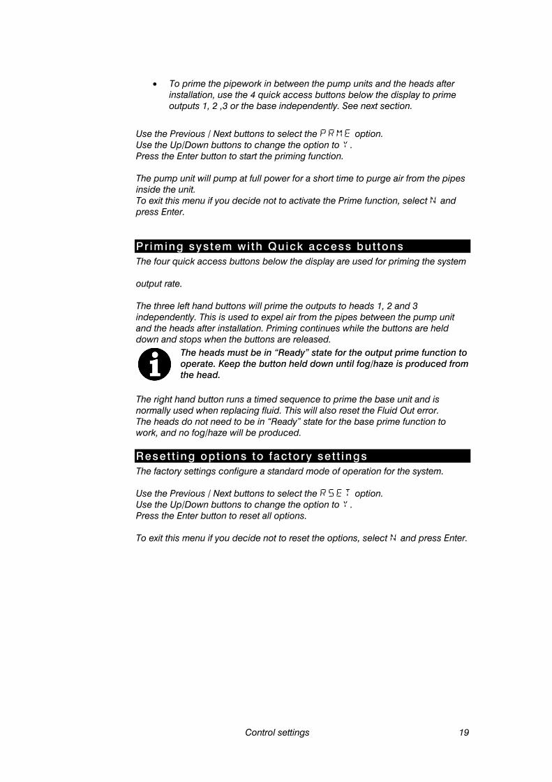
• To prime the pipework in between the pump units and the heads after
installation, use the 4 quick access buttons below the display to prime outputs 1, 2 ,3 or the base independently. See next section.
Use the Previous / Next buttons to select the option. Use the Up/Down buttons to change the option to . Press the Enter button to start the priming function. The pump unit will pump at full power for a short time to purge air from the pipes inside the unit. To exit this menu if you decide not to activate the Prime function, select and press Enter.
Pr iming system wi th Quick access but tons The four quick access buttons below the display are used for priming the system output rate. The three left hand buttons will prime the outputs to heads 1, 2 and 3 independently. This is used to expel air from the pipes between the pump unit and the heads after installation. Priming continues while the buttons are held down and stops when the buttons are released.
The heads must be in “Ready” state for the output prime function to operate. Keep the button held down until fog/haze is produced from the head.
The right hand button runs a timed sequence to prime the base unit and is normally used when replacing fluid. This will also reset the Fluid Out error. The heads do not need to be in “Ready” state for the base prime function to work, and no fog/haze will be produced.
Reset t ing opt ions to factory set t ings The factory settings configure a standard mode of operation for the system. Use the Previous / Next buttons to select the option. Use the Up/Down buttons to change the option to . Press the Enter button to reset all options. To exit this menu if you decide not to reset the options, select and press Enter.
20 Control settings
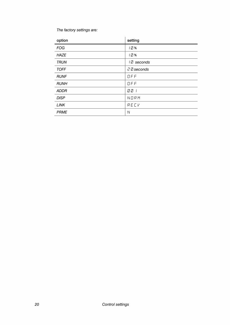
The factory settings are: option setting
FOG
HAZE
TRUN seconds
TOFF seconds
RUNF
RUNH
ADDR
DISP
LINK
PRME

Remote control 21
Remote control
Overv iew The digital remote control, available separately, may be used for remote control of the RUSH Club Smoke Dual™. Several systems may be controlled from one remote using the LINK function (see page 18).
Funct ions The remote control provides the following functions:
• Fog button: turns fog head output on and off. Press once to start output from fog heads and again to stop.
• Haze button: turns haze head output on and off. Press once to start output from haze heads and again to stop..
• Fog level setting (FOG = 0 -100%)
• Haze level setting (HAZE = 0 -100%)
• Timer run time/off time settings (TRUN = 0 -99 seconds, TOFF = 0-99 seconds)
• RunF – run mode for fog heads (RUN = OFF, STBY, TIME, CONT)
• RunH – run mode for haze heads (RUN = STBY, TIME, CONT) The functions are the same as on the built in control panel and are described on page 13. The RUN menu duplicates the functions of the Fog and Timer buttons. The buttons are simply a quick way to control this menu function.
Connect ion The remote control has two identical XLR connectors on the top and back for connection to the RUSH Club Smoke Dual™ system. The back connector allows the remote to be mounted into a panel or console. Plug the cable provided with the remote control into either of these sockets and into the 3-pin XLR plug nearest the mains switch on the top panel of the base pump unit (not the 3-pin DMX plug).
Display
Haze button
Fog button
XLR socket
XLR socket (on rear)

22 Remote control
The remote control is powered through its cable by the RUSH Club Smoke Dual™; no batteries are required. The cable may be extended to up to 25 m (82 ft.) with a 3-pin XLR DMX cable, available from your Martin dealer.

DMX control 23
DMX control
Overv iew DMX is a digital control system widely used in entertainment and architectural lighting. Any controller meeting the DMX-512 standard may be used to control and program the fog output of the RUSH Club Smoke Dual™.
When a DMX signal is present, the RUSH Club Smoke Dual™ stand-alone functions do not work. To fire the unit from the control panel or remote control, the DMX controller must be powered off or disconnected.
Connect ion The RUSH Club Smoke Dual™ system provides 3-pin and 5-pin XLR connectors on the top of the base pump unit for DMX connection. You can use either the 3-pin or 5-pin connectors for in or link through, but you should not use the unit as a splitter by connecting both the 3-pin and 5-pin outputs. For best results, use cable designed for high speed digital data transmission. Suitable DMX cable is available from your Martin dealer.
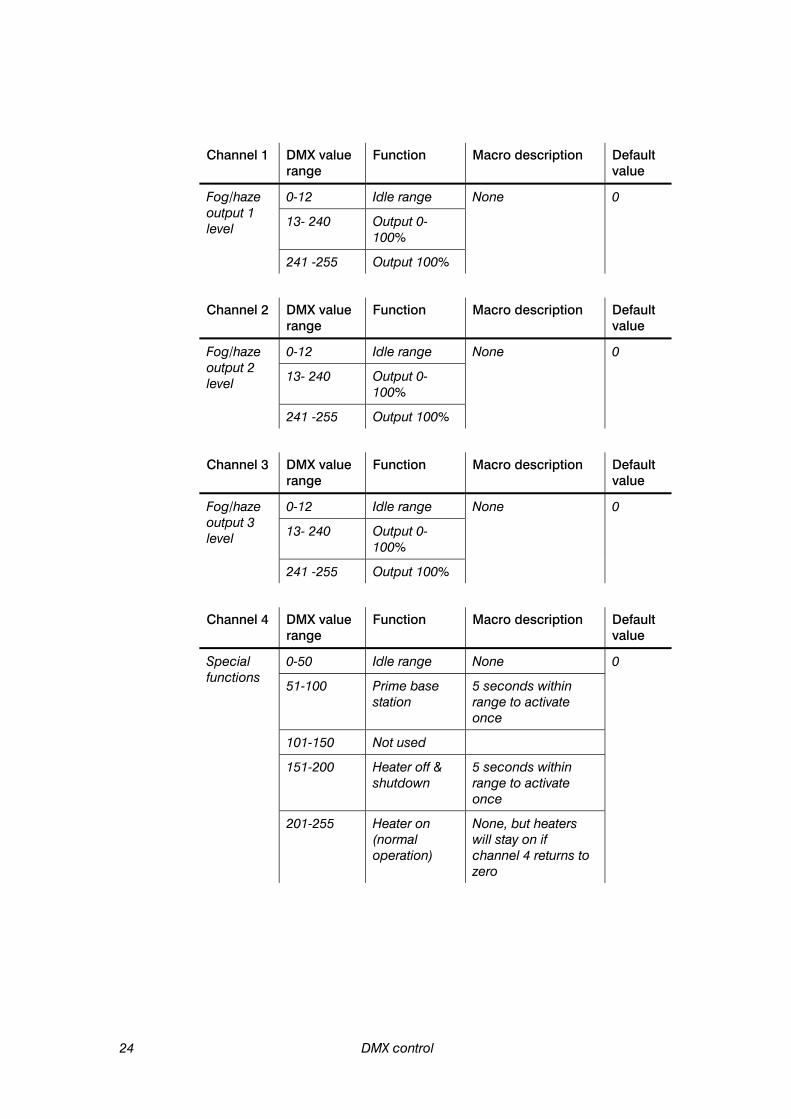
DMX funct ions The RUSH Club Smoke Dual™ address setting must match the DMX address allocated to it on your controller. To set the address, see “Setting the DMX base address” on page 18. The RUSH Club Smoke Dual™ requires four DMX channels. For example if the RUSH Club Smoke Dual™ is set to DMX address 100, channel 1 will be controlled by address 100, channel 2 will be controlled by address 101, channel 3 by address 102 and channel 4 by address 103. When the system is at running temperature and is under DMX control it displays . The functions of each DMX control channel are shown on the following page.
24 DMX control
Channel 1 DMX value range
Function Macro description Default value
Fog/haze output 1 level
0-12 Idle range None 0
13- 240 Output 0-100%
241 -255 Output 100%
Channel 2 DMX value range
Function Macro description Default value
Fog/haze output 2 level
0-12 Idle range None 0
13- 240 Output 0-100%
241 -255 Output 100%
Channel 3 DMX value range
Function Macro description Default value
Fog/haze output 3 level
0-12 Idle range None 0
13- 240 Output 0-100%
241 -255 Output 100%
Channel 4 DMX value range
Function Macro description Default value
Special functions
0-50 Idle range None 0
51-100 Prime base station
5 seconds within range to activate once
101-150 Not used
151-200 Heater off & shutdown
5 seconds within range to activate once
201-255 Heater on (normal operation)
None, but heaters will stay on if channel 4 returns to zero

Fog fluid types 25
Fog fluid types The RUSH Club Smoke Dual™ must only be used with RUSH Club Smoke Dual Fluid™. Martin supplies high quality fog fluids that are based on ultra-pure deionized water. No other fluid is suitable for use. To find your local dealer visit www.martin.com
DANGER! The RUSH Club Smoke Dual™ can run safely only on the specific fog fluid it is designed for. Use ONLY the Martin fog fluid designated in this manual. NEVER use any other type of fluid, or toxic gas may be produced. You will probably also cause damage to the system that will invalidate the product warranty. Do not dilute fog fluid with water or any other liquid. Discard fog fluid if it becomes contaminated.

26 Basic service
Basic service
Before servicing the RUSH Club Smoke Dual™, read and observe all the precautions listed in “Safety information” on page 5. Any service not described in this section must be carried out by a Martin service technician.
To find your local Martin service centre visit www.martin.com
Cleaning Excessive dust, fog fluid, and dirt build-up will degrade performance and cause overheating and damage to the system that is not covered by the product warranty. To maintain adequate cooling, dust must be cleaned from the outer casing and air vents of the system periodically.
Isolate the system from power and allow to cool completely before cleaning. The fog/haze output nozzles remain hot for a period after use.
• Remove dust from the air vents with a soft bRUSH, cotton swab, vacuum,
or compressed air.
• Clean fog fluid residues from the fog output of the system using a damp cloth.
• Clean the outer casing with a damp cloth only.
Fuse replacement The fuses for the system are located on the electronics board inside the units.
DANGER! Disconnect the power supply before removing any covers. Live parts inside!
To replace a fuse, disconnect the power cord from the supply, unscrew the screws holding the top cover of the unit and remove the cover. The electronics board is located in the compartment under the display. Remove the spent fuse and replace with one of exactly the same size and rating. The fuse type is indicated below. Contact Martin Service if the fuse blows repeatedly. Fog head 120 V = 10 AT 230 V = 6.3 AT Haze head 120 V = 10 AT 230 V = 6.3 AT Pump unit 120 V = 3.15 AT 230 V = 3.15 AT
Troubleshooting 27
Troubleshooting
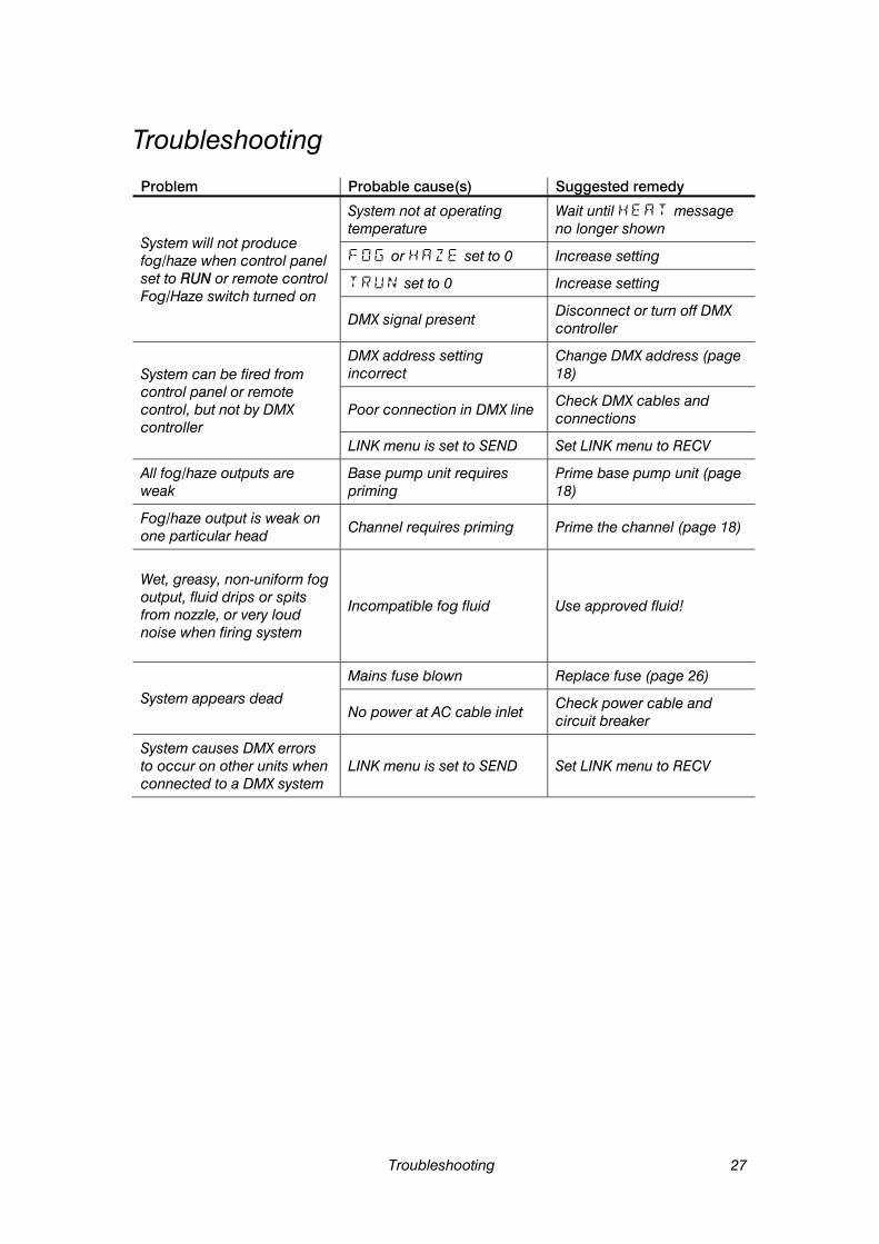
Problem Probable cause(s) Suggested remedy
System will not produce fog/haze when control panel set to RUN or remote control Fog/Haze switch turned on
System not at operating temperature
Wait until message no longer shown
or set to 0 Increase setting
set to 0 Increase setting
DMX signal present Disconnect or turn off DMX controller
System can be fired from control panel or remote control, but not by DMX controller
DMX address setting incorrect
Change DMX address (page 18)
Poor connection in DMX line Check DMX cables and connections
LINK menu is set to SEND Set LINK menu to RECV
All fog/haze outputs are weak
Base pump unit requires priming
Prime base pump unit (page 18)
Fog/haze output is weak on one particular head Channel requires priming Prime the channel (page 18)
Wet, greasy, non-uniform fog output, fluid drips or spits from nozzle, or very loud noise when firing system
Incompatible fog fluid Use approved fluid!
System appears dead
Mains fuse blown Replace fuse (page 26)
No power at AC cable inlet Check power cable and circuit breaker
System causes DMX errors to occur on other units when connected to a DMX system
LINK menu is set to SEND Set LINK menu to RECV
28 Status messages
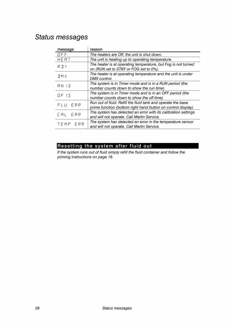
Status messages message reason The heaters are Off, the unit is shut down. The unit is heating up to operating temperature.
The heater is at operating temperature, but Fog is not turned on (RUN set to STBY or FOG set to 0%).
The heater is at operating temperature and the unit is under DMX control.
The system is in Timer mode and is in a RUN period (the number counts down to show the run time)
The system is in Timer mode and is in an OFF period (the number counts down to show the off time)
Run out of fluid. Refill the fluid tank and operate the base prime function (bottom right hand button on control display)
The system has detected an error with its calibration settings and will not operate. Call Martin Service.
The system has detected an error in the temperature sensor and will not operate. Call Martin Service.
Reset t ing the system af ter f lu id out If the system runs out of fluid simply refill the fluid container and follow the priming instructions on page 18.
Specifications 29
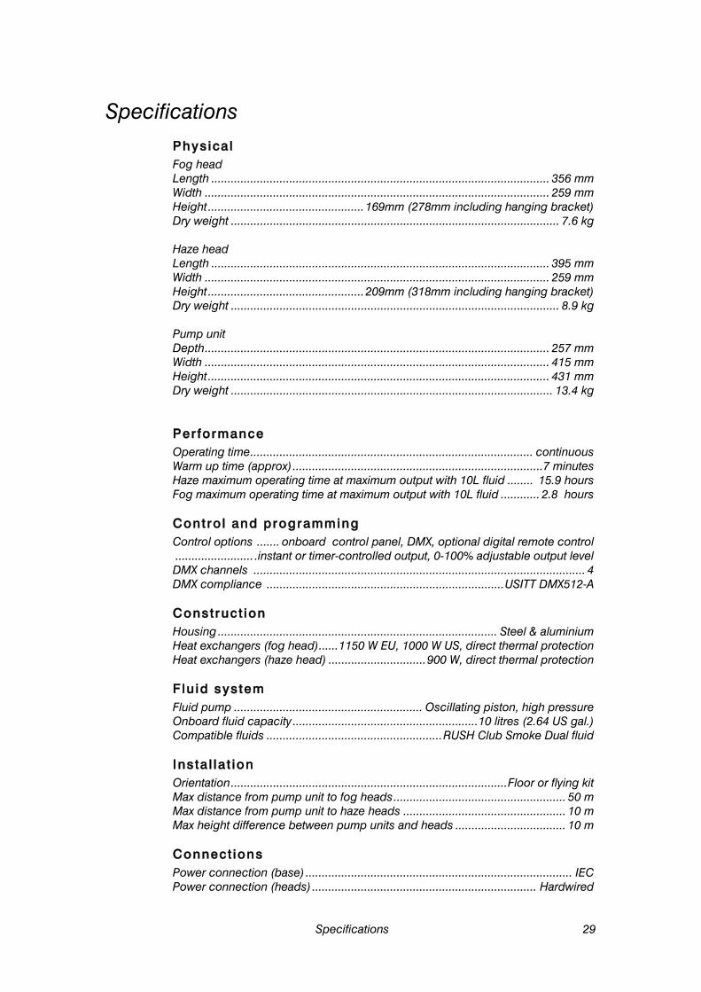
Specifications Physical Fog head Length ........................................................................................................ 356 mm Width .......................................................................................................... 259 mm Height ................................................ 169mm (278mm including hanging bracket) Dry weight ..................................................................................................... 7.6 kg Haze head Length ........................................................................................................ 395 mm Width .......................................................................................................... 259 mm Height ................................................ 209mm (318mm including hanging bracket) Dry weight ..................................................................................................... 8.9 kg Pump unit Depth .......................................................................................................... 257 mm Width .......................................................................................................... 415 mm Height ......................................................................................................... 431 mm Dry weight ................................................................................................... 13.4 kg
Performance Operating time ....................................................................................... continuous Warm up time (approx) .............................................................................7 minutes Haze maximum operating time at maximum output with 10L fluid ........ 15.9 hours Fog maximum operating time at maximum output with 10L fluid ............ 2.8 hours
Control and programming Control options ....... onboard control panel, DMX, optional digital remote control ........................ .instant or timer-controlled output, 0-100% adjustable output level DMX channels ...................................................................................................... 4 DMX compliance ......................................................................... USITT DMX512-A
Construct ion Housing ...................................................................................... Steel & aluminium Heat exchangers (fog head) ...... 1150 W EU, 1000 W US, direct thermal protection Heat exchangers (haze head) .............................. 900 W, direct thermal protection
Fluid system Fluid pump .......................................................... Oscillating piston, high pressure Onboard fluid capacity ......................................................... 10 litres (2.64 US gal.) Compatible fluids ...................................................... RUSH Club Smoke Dual fluid
Insta l la t ion Orientation ..................................................................................... Floor or flying kit Max distance from pump unit to fog heads ..................................................... 50 m Max distance from pump unit to haze heads .................................................. 10 m Max height difference between pump units and heads .................................. 10 m
Connect ions Power connection (base) .................................................................................. IEC Power connection (heads) ..................................................................... Hardwired
30 Specifications
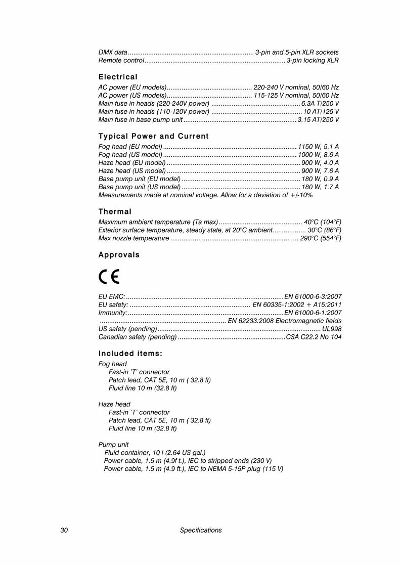
DMX data .................................................................... 3-pin and 5-pin XLR sockets Remote control ............................................................................ 3-pin locking XLR
Electr ica l AC power (EU models) .............................................. 220-240 V nominal, 50/60 Hz AC power (US models) .............................................. 115-125 V nominal, 50/60 Hz Main fuse in heads (220-240V power) ................................................ 6.3A T/250 V Main fuse in heads (110-120V power) ................................................. 10 AT/125 V Main fuse in base pump unit ............................................................. 3.15 AT/250 V
Typica l Power and Current Fog head (EU model) ........................................................................ 1150 W, 5.1 A Fog head (US model) ........................................................................ 1000 W, 8.6 A Haze head (EU model) ........................................................................ 900 W, 4.0 A Haze head (US model) ........................................................................ 900 W, 7.6 A Base pump unit (EU model) ................................................................ 180 W, 0.9 A Base pump unit (US model) ................................................................ 180 W, 1.7 A Measurements made at nominal voltage. Allow for a deviation of +/-10%
Thermal Maximum ambient temperature (Ta max) ............................................. 40°C (104°F) Exterior surface temperature, steady state, at 20°C ambient .................. 30°C (86°F) Max nozzle temperature ..................................................................... 290°C (554°F)
Approvals
EU EMC: ..................................................................................... EN 61000-6-3:2007 EU safety: ................................................................. EN 60335-1:2002 + A15:2011 Immunity: .................................................................................... EN 61000-6-1:2007 .................................................................... EN 62233:2008 Electromagnetic fields US safety (pending) ........................................................................................ UL998 Canadian safety (pending) .......................................................... CSA C22.2 No 104
Included i tems: Fog head
Fast-in ’T’ connector Patch lead, CAT 5E, 10 m ( 32.8 ft) Fluid line 10 m (32.8 ft) Haze head
Fast-in ’T’ connector Patch lead, CAT 5E, 10 m ( 32.8 ft) Fluid line 10 m (32.8 ft) Pump unit
Fluid container, 10 l (2.64 US gal.) Power cable, 1.5 m (4.9f t.), IEC to stripped ends (230 V) Power cable, 1.5 m (4.9 ft.), IEC to NEMA 5-15P plug (115 V)
Specifications 31
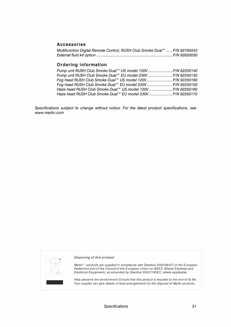
Accessor ies Multifunction Digital Remote Control, RUSH Club Smoke Dual™ ...... P/N 92765043 External fluid kit option ....................................................................... P/N 92620030
Order ing informat ion Pump unit RUSH Club Smoke Dual™ US model 120V ....................... P/N 92250140 Pump unit RUSH Club Smoke Dual™ EU model 230V ....................... P/N 92250130 Fog head RUSH Club Smoke Dual™ US model 120V ........................ P/N 92250160 Fog head RUSH Club Smoke Dual™ EU model 230V ........................ P/N 92250150 Haze head RUSH Club Smoke Dual™ US model 120V ...................... P/N 92250180 Haze head RUSH Club Smoke Dual™ EU model 230V ...................... P/N 92250170
Specifications subject to change without notice. For the latest product specifications, see www.martin.com
Disposing o f th is product
Martin™ products are supplied in compliance with Directive 2002/96/EC of the EuropeanParliament and of the Council of the European Union on WEEE (Waste E lectrical and Electronic Equipment), as amended by Directive 2003/108/EC, where applicable.
Help preserve the environment! Ensure that this product is recycled at the end of its life. Your supplier can give details of local arrangements for the disposal of Martin products.

www.martin.com • Olof Palmes Allé 18 • 8200 Aarhus N • Denmark Tel: +45 8740 0000 • Fax: +45 8740 0010