350-375.Monitor
27
Service Training MALAGA ELECTRONIC CONTROL SYSTEM Francis NOV 97 350/375/5080 Hydraulic Excavators
-
Upload
mohamed-bakheet -
Category
Documents
-
view
217 -
download
0
Transcript of 350-375.Monitor

8/8/2019 350-375.Monitor
http://slidepdf.com/reader/full/350-375monitor 1/27
Service TrainingMALAGA
ELECTRONIC CONTROL SYSTEM
FrancisNOV 97
350/375/5080 Hydraulic Excavators

8/8/2019 350-375.Monitor
http://slidepdf.com/reader/full/350-375monitor 2/272Page:
CHAPTER : Electronic Control System
350/375/5080Hydraulic Excavators
CONTROLLER
Relay Box
LED's

8/8/2019 350-375.Monitor
http://slidepdf.com/reader/full/350-375monitor 3/273Page:
CHAPTER : Electronic Control System
350/375/5080Hydraulic Excavators
OPERATOR'S CONSOLE
1
2
1. Monitor Panel2. Engine Speed Dial

8/8/2019 350-375.Monitor
http://slidepdf.com/reader/full/350-375monitor 4/274Page:
CHAPTER : Electronic Control System
350/375/5080Hydraulic Excavators
BACKUP SYSTEMS
ENGINE SPEED CONTROL
MANAUT
AUT
PUMP CONTROL
Engine Speed Control
Pump Control

8/8/2019 350-375.Monitor
http://slidepdf.com/reader/full/350-375monitor 5/275Page:
CHAPTER : Electronic Control System
350/375/5080Hydraulic Excavators
350/375 HYDRAULIC EXCAVATOR MONITOR
1
2
1
2
POWER TRAVEL SPEED AEC
ALARM CANCEL
WASHERWIPERLIGHT
TEST SERVICE
8/8/2019 350-375.Monitor
http://slidepdf.com/reader/full/350-375monitor 6/276Page:
CHAPTER : Electronic Control System
350/375/5080Hydraulic Excavators
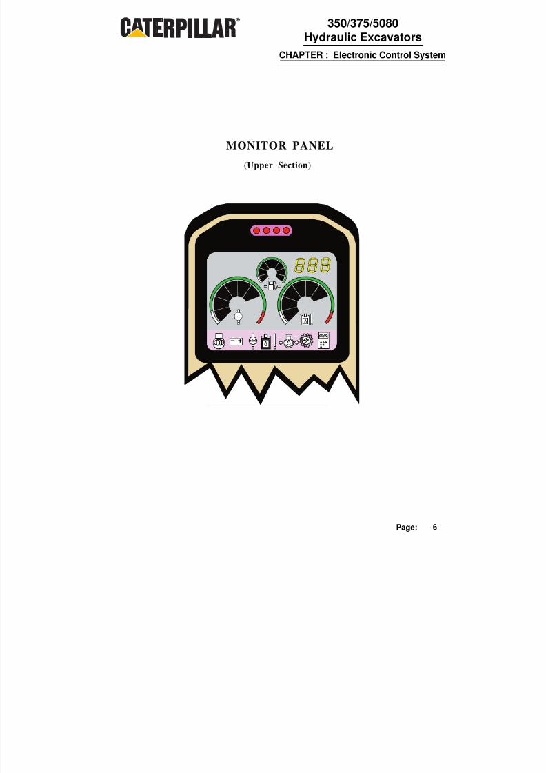
MONITOR PANEL
(Upper Section)

8/8/2019 350-375.Monitor
http://slidepdf.com/reader/full/350-375monitor 7/277Page:
CHAPTER : Electronic Control System
350/375/5080Hydraulic Excavators
• Communicates with the controller
• Has LCD displays in place of gauges
• Has push buttons that control many machine
functions and access diagnostic procedures
• Has a three digit character readout that...
- show s engine speed dial position- displays fault codes for controller/monitor
problems- indicates when either or both backupsystems are activated
THE MONITOR. . .
MONITOR FEATURES

8/8/2019 350-375.Monitor
http://slidepdf.com/reader/full/350-375monitor 8/278Page:
CHAPTER : Electronic Control System
350/375/5080Hydraulic Excavators
PULSE WIDTH MODULATED (PWM) SIGNALS
ONECYCLE
VOLTAGEON
MEAN VOLTAGE
VOLTAGEOFF
ONECYCLE
VOLTAGEON
VOLTAGELEVEL
MEAN VOLTAGE
VOLTAGEOFF
VOLTAGELEVEL
ONE
CYCLE
VOLTAGE
ON
VOLTAGELEVEL MEAN
VOLTAGE
VOLTAGEOFF
ONECYCLE
VOLTAGEON
VOLTAGELEVEL
MEANVOLTAGE
VOLTAGEOFF
DIFFERENT FREQUENCY

8/8/2019 350-375.Monitor
http://slidepdf.com/reader/full/350-375monitor 9/279Page:
CHAPTER : Electronic Control System
350/375/5080Hydraulic Excavators
INPUTS TO CONTROLLER
PUMP
CONTROLLER
1
2
3 4
5
6
7 8
910
1112
13
14
15
16
17
18
1. Monitor2. Eng Speed Dial3. Low Idle Switch4. Alternator5. Harness Code6. Battery7. Gov. Actuat.
Feedback Sensor
15. Swing Press. Switch16. Eng. Coolant
Temp. Sensor17. Hyd. Oil Temp. Sensor18. Fuel Level Sensor
19. Fuse Box
19
8. Speed Sensor9. Engine10. Start Switch11. Attch Press Sw itch12. Eng. Press . Sw ich13. Travel Press. Sw itch
14. Impl. Press. Switch
8/8/2019 350-375.Monitor
http://slidepdf.com/reader/full/350-375monitor 10/2710Page:
CHAPTER : Electronic Control System
350/375/5080Hydraulic Excavators
PUMP
CONTROLLER
1
2 34 5
6 7
8
9
10
11
12
13
1415
161718
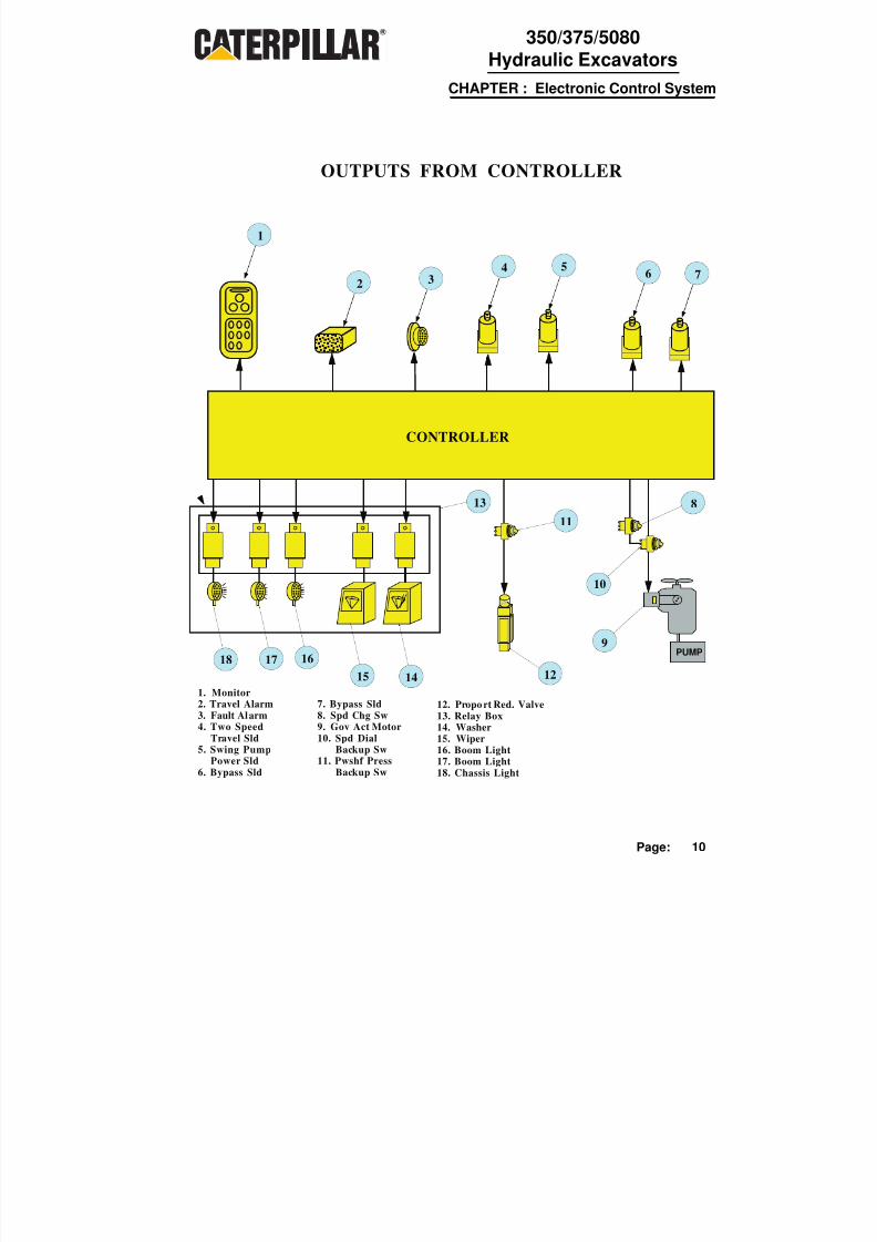
OUTPUTS FROM CONTROLLER
7. Bypass Sld8. Spd Chg Sw9. Gov Act Motor10. Spd Dial
Backup Sw11. Pwshf Press
Backup Sw
1. Monitor2. Travel Alarm3. Fault Alarm4. Two Speed
Travel Sld5. Swing Pump
Power Sld6. Bypass Sld
12. Proport Red. Valve13. Relay Box14. Washer15. Wiper16. Boom Light17. Boom Light18. Chassis Light

8/8/2019 350-375.Monitor
http://slidepdf.com/reader/full/350-375monitor 11/2711Page:
CHAPTER : Electronic Control System
350/375/5080Hydraulic Excavators
POWER MODE SELECTION
1
2
1
2
POWER TRAVEL SPEED AEC
ALARM CANCEL
WASHERWIPERLIGHT
TESTSERVICE

8/8/2019 350-375.Monitor
http://slidepdf.com/reader/full/350-375monitor 12/27
1 2
P age:
PUMP CONTROLSPOWER MODE SELECTION
PUMP
ECU
1
2
3
4
5
6
7
a
98
b
a. PS Press From PRVb. Swing Pump Outputc. Power Shif t Press Signal
1. Monitor2. Eng. Speed Dial3. Travel Press Sw itch4. Impl Press Switch5. Swi ng Press Switch6. Attch Press Sw itch7. Propor Reduc Valve8. Engine9. Speed Sensor

8/8/2019 350-375.Monitor
http://slidepdf.com/reader/full/350-375monitor 13/2713Page:
CHAPTER : Electronic Control System
350/375/5080Hydraulic Excavators
III
II
I
1
2
1
2
PUMP
ECU(CONTROLLER)
POWER
l l l
l
l l
SPEED DIAL LIMITS
1
2
34
56
7
8
1. Monitor2. Eng Speed Dial3. Proport Reduc Valve4. Gov Actuator5. Engine
6. Feedback Sensor7. Speed Sensor8. Power Mode Switch
DialPosition
RPM
1 8002 9503 11104 12605 14106 15707 1720
8 18709 203010 2200
350
70085010001150130014501600
175018601960
375

8/8/2019 350-375.Monitor
http://slidepdf.com/reader/full/350-375monitor 14/2714Page:
CHAPTER : Electronic Control System
350/375/5080Hydraulic Excavators
AUTOMATIC ENGINE SPEED CONTROL (AEC)
ECU
IIIII
I
1
2
1
2
ON1
2
3
4
5
6
7
10
8
9
1. Monitor2. AEC Switch3. Impl Press Sw itch4. Travel Press Sw itch5. Swing Press Switch6. Attch Press Sw itch7. Gov Actuator8. Engine9. Speed Sensor10. Feedback Sensor

8/8/2019 350-375.Monitor
http://slidepdf.com/reader/full/350-375monitor 15/2715Page:
CHAPTER : Electronic Control System
350/375/5080Hydraulic Excavators
ECU
ON E-TOUCH LOW IDLE CON TROL CIRCUIT
1
2
3
4
5
6
8
9
10
7
1. Low Idle Switch
2. Engine Speed Switch3. Impl Press Switch4. Travel Press Sw itch5. Swing Press Switch6. Attch Press Switch7. Gov Actuator8. Engine9. Speed Sensor10. Feedback Sensor

8/8/2019 350-375.Monitor
http://slidepdf.com/reader/full/350-375monitor 16/2716Page:
CHAPTER : Electronic Control System
350/375/5080Hydraulic Excavators
BACKUP SYSTEM CIRCUITS
24V
24V
ECU
PRVDRIVER
PRV
M
AUT MAN
AUT TOR
RAB TOR
(Normal Operation)
1
2
34
5
6
PRV7
8
9
1. Governor ActDrive Circuit
2. Backup Signal3. Backup Detection4. Backup Resistor5. Pump Control
Backup Switch6. PRV7. Engine Speed
Change Swi tch8. Governor Actuator9. Eng Speed Dial
Backup Switch

8/8/2019 350-375.Monitor
http://slidepdf.com/reader/full/350-375monitor 17/2717Page:
CHAPTER : Electronic Control System
350/375/5080Hydraulic Excavators
BACKUP SYSTEM CIRCUITS
24V
24V
ECU
PRVDRIVER
PRV
M
AUT MAN
AUT TOR
RAB TOR
(Engine Speed Dial Backup System "ON ")
1
2
34
5
6
PRV7
8
9
1. Governor ActDrive Circuit
2. Backup Signal
3. Backup Detection4. Backup Resistor5. Pump Control
Backup Switch6. PRV7. Engine Speed
Change Switch8. Governor Actuator9. Eng Speed Dial
Backup Switch

8/8/2019 350-375.Monitor
http://slidepdf.com/reader/full/350-375monitor 18/2718Page:
CHAPTER : Electronic Control System
350/375/5080Hydraulic Excavators
BACKUP SYSTEM CIRCUITS
24V
24V
ECU
PRVDRIVER
PRV
M
AUT MAN
AUT TOR
RAB TOR
(Pump Control Backup System 'ON")
1
2
3
4
5
6
7
8
9
1. Governor ActDrive Circuit
2. Backup Signal
3. Backup Detection4. Backup Resistor5. Pump Control
Backup Switch6. PRV7. Engine Speed
Change Switch8. Governor Actuator9. Eng Speed Dial
Backup Switch

8/8/2019 350-375.Monitor
http://slidepdf.com/reader/full/350-375monitor 19/2719Page:
CHAPTER : Electronic Control System
350/375/5080Hydraulic Excavators
PERFORMANCE MONITOR

8/8/2019 350-375.Monitor
http://slidepdf.com/reader/full/350-375monitor 20/2720Page:
CHAPTER : Electronic Control System
350/375/5080Hydraulic Excavators
SERVICE FUNCTIONS
POWER
LIGHT WIPER WASHER
AECTRAVEL SPEED
ALARM CANCEL
12
1
2
INFORMATION PROVIDED
1. Power Shift Pressure
2. Engine Speed
3. Engine Coolant Temperature
4. Hydraulic Oil Temperature
5. Analog / Digital Conversion
6. Real Time Error
7. Digital input
8. Pump Output Control
DATA MODE

8/8/2019 350-375.Monitor
http://slidepdf.com/reader/full/350-375monitor 21/2721Page:
CHAPTER : Electronic Control System
350/375/5080Hydraulic Excavators
CALIBRATION MODE
POWER
LIGHT WIPER WASHER
AECTRAVEL SPEED
ALARM CANCEL
1
2
1
2
CALIBRATION MODE
INFORMATION PROVIDED
1. Machine Model and Configuration
2. Controller / Monitor Software Version
3. Error Log
4. Digital Output Test
5. PRV Sweep Test
6. Engine Speed Change
7. Fixed Power shift Pressure Setting
8. Engine RPM Display
9. Automatic Governor Actuator Calibration
10. PRV Calibration
8/8/2019 350-375.Monitor
http://slidepdf.com/reader/full/350-375monitor 22/2722Page:
CHAPTER : Electronic Control System
350/375/5080Hydraulic Excavators
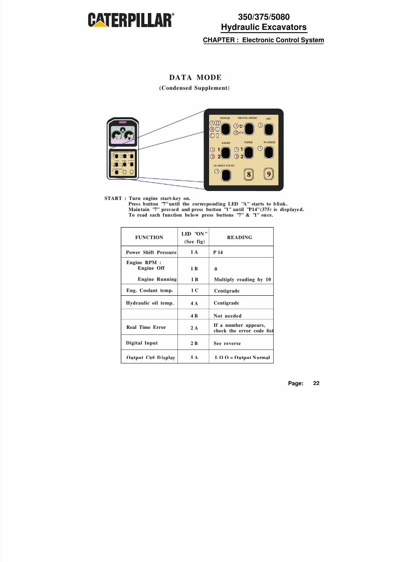
(Condensed Supplement)
DATA MODE
12
12
POWER TRAVELSPEED AEC
ALARM CANCEL
WASHERWIPERLIGHT
1
2
1
2
POWER TRAVEL SPEED AEC
ALARM CANCEL
WASHERWIPERLIGHT
1A
4
7
2
5
8
3
6
9
B
C
A
B
A
B
A
B
A
A
A
START : Turn engine start-key on.Press button "7" until the corresponding LED "A" starts to blink.
Maintain "7" pressed and press button "1" until "P14" (375) is displaye d.To read each function below press buttons "7" & "1" once.
FUNCTIONLED "ON "
(See fig)READING
Power Shift Pressure
Engine RPM :Engine Off
Engine Running
Eng. Coolant temp.
Hydraulic oil temp.
Real Time Error
1 A
1 B
1 B
1 C
4 A
4 B
2 A
2 B
P 14
0
Multiply reading by 10
Centigrade
Centigrade
Not needed
If a number appears,check the error code list
Digital Input See reverse
Output Ctrl D isplay 5 A L O O = Output Normal

8/8/2019 350-375.Monitor
http://slidepdf.com/reader/full/350-375monitor 23/2723Page:
CHAPTER : Electronic Control System
350/375/5080Hydraulic Excavators
(Condensed Supplement Cont.)
DATA MODE
12
12
POWER TRAVELSPEED AEC
ALARM CANCEL
WASHERWIPERLIGHT
LED "2 B" blinkingTo change readings from "0" to "p", press buttons "7" & "8" once.
DIGITAL INPUT TESTS
0123456789ABCDEFHJL
np
Harness codeEngine Speed Dial positionTravel pressure switchAttach. pump pressure switch (Optional)Engine oil pressure switchOpenOpenOpenLow idle switchImplement pressure switchEngine RPM back-up switchPRV Back-up switchOpenEngine start key SwitchSwing pressure switchAlternator condition (Eng. running)OpenOpenOpen
OpenOpen
010 (350) 012 (375)1 to 10
ON / OFFOFF
ON / OFFOFFOFFOFF
ON / OFFON / OFFON / OFFON / OFF
OFFON
ON / OFFONOFFOFFOFF
OFFOFF
Port Component Indication
1
2
1
2
POWER TRAVEL SPEED AEC
ALARM CANCEL
WASHERWIPERLIGHT
1A
4
7
2
5
8
3
6
9
B
C
A
B
A
B
A
B
A
A
A

8/8/2019 350-375.Monitor
http://slidepdf.com/reader/full/350-375monitor 24/2724Page:
CHAPTER : Electronic Control System
350/375/5080Hydraulic Excavators
(Condensed Supplement)
CALIBRATION MODE
1
2
1
2
POWER TRAVELSPEED AEC
ALARM CANCEL
WASHERWIPERLIGHT
FUNCTIONLED
"ON"READING
1 A
1 B
1 C
PREESSBUTTON
9
1
1
4
5 5A
5 5B
Machine model 75 (375) = 75 Tons. b = Backhoe Config.
Computer software00C (for examp) C = Contr. P = Monit.
Error Log Hd is displayed,Press button "3" for ascending order,"6" for descending order. End at theend. To clear press "3", "1" and "2"simultaneously until CLr is diplayed.
Digital output Test 4 4A OoF is displayed,
press button "3" for ascending order,"6" for descending order. Press "7"to check "O n / o F"
Proportional ReducingValve "Sweep Test"
4B Pressure changes from 0 to 32 Bar(in 5 sec.) and back.
Engine Speed Change(change for testpurposes)
Press button "3" to increase RPM and"6" to decrease.(Indication X 10 = RPM)
Fixed Power shift
pressure(change for testpurposes)
P25 (for exemple) is displayed, press
button "3" to increse the pressure, "6"to decrease. Each touch changes 1 Bar.Press "7" to change from power shiftpressure to RPM and back
( F01 - F48. CheckError code list )
START : With the engine s tart-key in the off pos ition , press "9" on pane l.Maintain "9" pressed and turn start-key to on position. Continue pressing"9" til l "45b" (350) "75b" (375) displayed , then start the engine.
Press button "3" to change "C" and "P"
1
2
1
2
POWER TRAVEL SPEED AEC
ALARM CANCEL
WASHERWIPERLIGHT
1
A
4
7
2
5
8
3
6
9
BC
A
B
A
B
A
B
A
A
A

8/8/2019 350-375.Monitor
http://slidepdf.com/reader/full/350-375monitor 25/2725Page:
CHAPTER : Electronic Control System
350/375/5080Hydraulic Excavators
(Condensed Supplement Cont.)CALIBRATION MODE
1
2 12
POWER TRAVELSPEED AEC
ALARM CANCEL
WASHERWIPERLIGHT
FUNCTIONLED"ON"
READINGPRESS
BUTTON
2 2B
Engine Speed DialSetting Check
2 2A
Governor calibration(Move throttle controlto 10)
2A
Power shift calibration
NOTA : To end, press button "9" till monitor changes to normal or : Turn-off eng ine
start-key.
Character displays the engine rpmvalue characteristic to the setting of the engine speed dial sw itch pos ition
Press and hold "3" and "6". AC flashingappears. While depressing "3" and "6"press "7" until display changes to ACP.Release all buttons then ACt willappear. Press "3" and "6" once more tostart the Auto. Calibration Program(display will change from AC1 to AC0)If Problem : check Auto. CalibrationError Table.
"E" Displayed - Move throttle controlto position 10
"1" Displayed - First calibr. - 5 kg/cm2"2" Displayed - Sec. Calibr. - 25 kg/cm2
Press "3" to increase and "6" to decrease.Press button "7" to store the new settingsin memory. Each time "7" is pressed, thedisplay changes from first to secondcalibration.
1
2
1
2
POWER TRAVEL SPEED AEC
ALARM CANCEL
WASHERWIPERLIGHT
1A
4
7
2
5
8
3
6
9
B
C
A
B
A
B
A
B
A
A
A

8/8/2019 350-375.Monitor
http://slidepdf.com/reader/full/350-375monitor 26/2726Page:
CHAPTER : Electronic Control System
350/375/5080Hydraulic Excavators
REAL TIME ERROR CODES
* CODE No DESCRIPTION OF PROBLEMS
E00E01E02E03E04
E05E06E07E09E10E11E12E13E14E15E16
E17E18E19E20E21E25E26E27E28E29E30E31E32E33E34E36E37E38E39E40E41E48
No problem.Engine oil pressure: Low.Engine coolant temperature: High.Hydraulic oil temperature: High.Battery vol tage: (Over 43 V).
Alternator terminal "R": open.Engine speed sensor malfunction (no or low signal).Engine speed is not normal.Voltage of governor actuator feedback sensor: Low.Cir. of gover. actuat. feedback sensor: Shorted/open to batt.vol t.Cir. of gover. actuat. feedback sensor: Shorted to body gnd.Voltage of governor actuator feedback sensor: Not stable.Circuit of governor actuator motor: Shorted to body ground.Gover. actuat. mtr does not rotate or mtr crct.: Shorted to gnd.Spd d ial backup sw i s "on" or gover. actuat. mtr. crct.: Open.Proportional Reduction Valve (PRV) crct.: Shorted to body gnd.
PRV circuit: Shorted to battery vol tage.PRV circuit: Open.Attach. Puls With Modulation (PWM) output: Gnd shorted.Attach. PWM output: + B shorted.Attach. PWM output: Open.Crct. of eng. coolant temperature sensor: Shorted to body gnd.Crct. of eng. coolant temp. sensor: Shorted to batt. vol . or open.Crct. of hydraulic oil temp. sensor: Shorted to body gnd.Crct. of hydraulic oil temp. sensor: Shoted to batt. volt or open .Attach. PWM Input: Shorted to gnd.Attach. PWM input: + B shorted or open.Throttle dial and eng. rpm signals to controller: Mismatched
Dial set. and act. eng. rpm: More than 100 rpm diff .Digi tal output circuit: Shorted to batt. voltage.Gover. actuat.: N o movement for 2.5 sec. after spd dial setting.Monitor takes at least 1 sec. to respond to controller 's signal.Monitor RAM (Random Access Memory): Not normal.Controller feels error signal from monitor.Monitor feels error from controller.Controller memory: ErrorController program indicates not-existing machine model.Engine Stalls.
NOTE : E 33 Shows w henever a short occurs on the two-speed solenoid.
* E: In Data ModeF: In Calibration Mode

8/8/2019 350-375.Monitor
http://slidepdf.com/reader/full/350-375monitor 27/27
CHAPTER : Electronic Control System
350/375/5080Hydraulic Excavators
Left Hand Display Test Items
0 Action alarm buzzer1 Washer Relay
Wiper Relay
Boom Light Relay
Chassis Light RelayTwo Speed Travel So lenoid *
Open
Open
5
6
78
9
A
DIGITAL OUTPUT TEST
b Travel Alarm Buzzer
F
Swing Control PowerSolenoidBypass Solenoid (Bm / Travel)OpenPRV Solenoid
2 Relay (Attachment)
3 Relay (Attachment)
4 Bypass soleno id valve (Bkt/Stk)
C
dE
* Only Short = Err
A C 1
A C 2
Check dial pos 2-9
Check hi RPM
A C 3 Check dial pos 9-2
A C 4 Check li RPM
A C 5 Comp. prosse s of inputs
A C 6 Confirm dial pos 2-10
A C 7
A C 8
A C 0
Store in memory
Samp data rpm ctr
End
*
*
GOVERNOR AUTOMATIC CALIBRATION ERROR TABLE
ErrorCode
- 1 Governor actuator (G / A) cable does not move freely .- 2 The difference of the inward and outward movements of G / A are too large.- 3 G / A needs too much response time- 4 Battery voltage is to high. - Same as Real Time Error (RTE) : E04.- 5 Vol tage of G / A feedback sensor is to low . - Same as RTE : E09.- 6 Circuit of G / A feedback sensor is shorted to batt.vol t. or open. - Same as RTE : E10.- 7 Circuit of G / A feedback sensor is shorted to body ground. - Same as RTE : E11.- 8 Vol tage of G / A feedback sensor is not stable . - Same as RTE : E12.- 9 Circuit of G / A motor is shorted to body ground. - Same as RTE : E13.- 10 G / A motor does not rotates or mtr. crct. is shorted to body gnd. - Same as RTE : E14.- 11 Speed dial backup is "ON " or G / A motor circuit is open. - Same as RTE : E15.- 12 Speed sensor circuit is ope n. - Same as RTE E06.- 13 Pressure sw itch for implement / sw ing or travel is "ON ." Any of controls are in act. pos .- 14 Controll er program indicates non-existing machine model . - Same as RTE : E41.- 15 G / A does not move freely near LOW or HIGH idle position- 16 G / A does not move freely near LOW IDLE position
- 51 The specified high idle speed is not obtained- 52 The accelerator cable has to much tension (one cable system only)- 53 The accelerator cable is to loose (one cable system only)
Description of problem
* Steps AC5/7 are completedsimultaneously.
GOVERNOR CALIBRATIONSEQUENCE
CALIBRATIONDATA